Diagnostic apparatus to extract nucleic acids including a magnetic assembly and a heater assembly
Duffy , et al. November 24, 2
U.S. patent number 10,844,368 [Application Number 16/246,782] was granted by the patent office on 2020-11-24 for diagnostic apparatus to extract nucleic acids including a magnetic assembly and a heater assembly. This patent grant is currently assigned to HandyLab, Inc.. The grantee listed for this patent is HandyLab, Inc.. Invention is credited to Patrick Duffy, Kalyan Handique, Jeff Williams, Kerry Wilson.


View All Diagrams
| United States Patent | 10,844,368 |
| Duffy , et al. | November 24, 2020 |
Diagnostic apparatus to extract nucleic acids including a magnetic assembly and a heater assembly
Abstract
A rack for holding samples and various reagents, wherein the rack may be used for loading the samples and reagents prior to using the reagents. The rack accepts complementary reagent holders, each of which contain a set of reagents for carrying out a predetermined processing operation, such as preparing biological samples for amplifying and detecting polynucleotides extracted from the samples.
| Inventors: | Duffy; Patrick (Whitmore Lake, MI), Wilson; Kerry (Elkhart, IN), Handique; Kalyan (Ypsilanti, MI), Williams; Jeff (Chelsea, MI) | ||||||||||
|---|---|---|---|---|---|---|---|---|---|---|---|
| Applicant: |
|
||||||||||
| Assignee: | HandyLab, Inc. (Franklin Lakes,
NJ) |
||||||||||
| Family ID: | 1000005201326 | ||||||||||
| Appl. No.: | 16/246,782 | ||||||||||
| Filed: | January 14, 2019 |
Prior Publication Data
| Document Identifier | Publication Date | |
|---|---|---|
| US 20190144849 A1 | May 16, 2019 | |
Related U.S. Patent Documents
| Application Number | Filing Date | Patent Number | Issue Date | ||
|---|---|---|---|---|---|
| 15017977 | Feb 8, 2016 | 10179910 | |||
| 13474980 | May 18, 2012 | ||||
| 12178584 | May 22, 2012 | 8182763 | |||
| 12173023 | Mar 13, 2012 | 8133671 | |||
| 12218498 | Nov 17, 2015 | 9186677 | |||
| 60959437 | Jul 13, 2007 | ||||
| Current U.S. Class: | 1/1 |
| Current CPC Class: | B01L 3/5082 (20130101); F16K 99/003 (20130101); F16K 99/0032 (20130101); G01N 35/026 (20130101); F16K 99/0001 (20130101); B01L 7/52 (20130101); G01N 35/1002 (20130101); F16K 99/0044 (20130101); G01N 35/0099 (20130101); B01L 9/527 (20130101); B01L 9/06 (20130101); C12N 15/1003 (20130101); F16K 99/0061 (20130101); Y10T 436/113332 (20150115); B01L 2200/16 (20130101); G01N 2035/0493 (20130101); F16K 2099/0084 (20130101); G01N 2035/00772 (20130101); G01N 2035/00881 (20130101); G01N 2035/00801 (20130101) |
| Current International Class: | C12N 15/10 (20060101); B01L 3/00 (20060101); G01N 35/10 (20060101); G01N 35/02 (20060101); F16K 99/00 (20060101); B01L 7/00 (20060101); B01L 9/06 (20060101); G01N 35/00 (20060101); B01L 9/00 (20060101); G01N 35/04 (20060101) |
| Field of Search: | ;436/43,47,94,147,174,177,178,180 ;422/63,65,68.1,509,527,560,561,562,565 ;435/287.1,287.2 |
References Cited [Referenced By]
U.S. Patent Documents
| D189404 | December 1960 | Nicolle |
| 3050239 | August 1962 | Williams |
| 3905772 | September 1975 | Hartnett et al. |
| 3985649 | October 1976 | Eddelman |
| 4018089 | April 1977 | Dzula et al. |
| 4018652 | April 1977 | Lanham et al. |
| 4038192 | July 1977 | Serur |
| 4055395 | October 1977 | Honkawa et al. |
| D249706 | September 1978 | Adamski |
| 4139005 | February 1979 | Dickey |
| D252157 | June 1979 | Kronish et al. |
| D252341 | July 1979 | Thomas |
| D254687 | April 1980 | Fadler et al. |
| 4212744 | July 1980 | Oota |
| D261033 | September 1981 | Armbruster |
| D261173 | October 1981 | Armbruster |
| 4301412 | November 1981 | Hill et al. |
| 4439526 | March 1984 | Columbus |
| 4457329 | July 1984 | Werley et al. |
| 4466740 | August 1984 | Kano et al. |
| 4472357 | September 1984 | Levy et al. |
| 4504582 | March 1985 | Swann |
| 4522786 | June 1985 | Ebersole |
| D279817 | July 1985 | Chen et al. |
| D282208 | January 1986 | Lowry |
| 4599315 | July 1986 | Terasaki et al. |
| 4612873 | September 1986 | Eberle |
| 4612959 | September 1986 | Costello |
| D288478 | February 1987 | Carlson et al. |
| 4647432 | March 1987 | Wakatake |
| 4654127 | March 1987 | Baker et al. |
| 4673657 | June 1987 | Christian |
| 4678752 | July 1987 | Thorne et al. |
| 4683195 | July 1987 | Mullis et al. |
| 4683202 | July 1987 | Mullis |
| 4698302 | October 1987 | Whitehead et al. |
| D292735 | November 1987 | Lovborg |
| 4720374 | January 1988 | Ramachandran |
| 4724207 | February 1988 | Hou et al. |
| 4798693 | January 1989 | Mase et al. |
| 4800022 | January 1989 | Leonard |
| 4827944 | May 1989 | Nugent |
| 4841786 | June 1989 | Schulz |
| D302294 | July 1989 | Hillman |
| 4855110 | August 1989 | Marker et al. |
| 4871779 | October 1989 | Killat et al. |
| 4895650 | January 1990 | Wang |
| 4919829 | April 1990 | Gates et al. |
| 4921809 | May 1990 | Schiff et al. |
| 4935342 | June 1990 | Seligson et al. |
| 4946562 | August 1990 | Guruswamy |
| 4949742 | August 1990 | Rando et al. |
| D310413 | September 1990 | Bigler et al. |
| 4963498 | October 1990 | Hillman |
| 4967950 | November 1990 | Legg et al. |
| D312692 | December 1990 | Bradley |
| 4978502 | December 1990 | Dole et al. |
| 4978622 | December 1990 | Mishell et al. |
| 4989626 | February 1991 | Takagi et al. |
| 5001417 | March 1991 | Pumphrey et al. |
| 5004583 | April 1991 | Guruswamy et al. |
| 5048554 | September 1991 | Kremer |
| 5053199 | October 1991 | Keiser et al. |
| 5060823 | October 1991 | Perlman |
| 5061336 | October 1991 | Soane |
| 5064618 | November 1991 | Baker et al. |
| 5071531 | December 1991 | Soane |
| 5091328 | February 1992 | Miller |
| D324426 | March 1992 | Fan et al. |
| 5096669 | March 1992 | Lauks et al. |
| D325638 | April 1992 | Sloat et al. |
| 5126002 | June 1992 | Iwata et al. |
| 5126022 | June 1992 | Soane et al. |
| D328135 | July 1992 | Fan et al. |
| D328794 | August 1992 | Frenkel et al. |
| 5135627 | August 1992 | Soane |
| 5135872 | August 1992 | Pouletty et al. |
| 5147606 | September 1992 | Charlton et al. |
| 5169512 | December 1992 | Wiedenmann et al. |
| D333522 | February 1993 | Gianino |
| 5186339 | February 1993 | Heissler |
| 5192507 | March 1993 | Taylor et al. |
| 5208163 | May 1993 | Charlton et al. |
| 5217694 | June 1993 | Gibler et al. |
| 5223226 | June 1993 | Wittmer et al. |
| 5229297 | July 1993 | Schnipelsky et al. |
| D338275 | August 1993 | Fischer et al. |
| 5250263 | October 1993 | Manz |
| 5252743 | October 1993 | Barrett et al. |
| 5256376 | October 1993 | Callan et al. |
| 5273716 | December 1993 | Northrup et al. |
| 5275787 | January 1994 | Yuguchi et al. |
| 5282950 | February 1994 | Dietze et al. |
| 5296375 | March 1994 | Kricka et al. |
| 5304477 | April 1994 | Nagoh et al. |
| 5304487 | April 1994 | Wilding et al. |
| D347478 | May 1994 | Pinkney |
| 5311896 | May 1994 | Kaartinen et al. |
| 5311996 | May 1994 | Duffy et al. |
| 5316727 | May 1994 | Suzuki et al. |
| 5327038 | July 1994 | Culp |
| 5339486 | August 1994 | Persic, Jr. |
| D351475 | October 1994 | Gerber |
| D351913 | October 1994 | Hieb et al. |
| 5364591 | November 1994 | Green et al. |
| 5372946 | December 1994 | Cusak et al. |
| 5374395 | December 1994 | Robinson |
| 5389339 | February 1995 | Petschek et al. |
| D356232 | March 1995 | Armstrong et al. |
| 5397709 | March 1995 | Berndt |
| 5401465 | March 1995 | Smethers et al. |
| 5411708 | May 1995 | Moscetta et al. |
| 5414245 | May 1995 | Hackleman |
| 5415839 | May 1995 | Zaun et al. |
| 5416000 | May 1995 | Allen et al. |
| 5422271 | June 1995 | Chen et al. |
| 5422284 | June 1995 | Lau |
| 5427946 | June 1995 | Kricka et al. |
| 5443791 | August 1995 | Cathcart et al. |
| 5474796 | December 1995 | Brennan |
| 5475487 | December 1995 | Mariella, Jr. et al. |
| D366116 | January 1996 | Biskupski |
| 5486335 | January 1996 | Wilding et al. |
| 5494639 | February 1996 | Grzegorzewski |
| 5498392 | March 1996 | Wilding et al. |
| 5503803 | April 1996 | Brown |
| 5516410 | May 1996 | Schneider et al. |
| 5519635 | May 1996 | Miyake et al. |
| 5529677 | June 1996 | Schneider et al. |
| 5559432 | September 1996 | Logue |
| 5565171 | October 1996 | Dovichi et al. |
| 5569364 | October 1996 | Hooper et al. |
| 5578270 | November 1996 | Reichler et al. |
| 5578818 | November 1996 | Kain et al. |
| 5579928 | December 1996 | Anukwuem |
| 5580523 | December 1996 | Bard |
| 5582884 | December 1996 | Ball et al. |
| 5582988 | December 1996 | Backus et al. |
| 5585069 | December 1996 | Zanucchi et al. |
| 5585089 | December 1996 | Queen et al. |
| 5585242 | December 1996 | Bouma et al. |
| 5587128 | December 1996 | Wilding et al. |
| 5589136 | December 1996 | Northrup et al. |
| 5593838 | January 1997 | Zanzucchi et al. |
| 5595708 | January 1997 | Berndt |
| 5599432 | February 1997 | Manz et al. |
| 5599503 | February 1997 | Manz et al. |
| 5599667 | February 1997 | Arnold, Jr. et al. |
| 5601727 | February 1997 | Bormann et al. |
| 5603351 | February 1997 | Cherukuri et al. |
| 5605662 | February 1997 | Heller et al. |
| 5609910 | March 1997 | Hackleman |
| D378782 | April 1997 | LaBarbera et al. |
| 5628890 | May 1997 | Carter et al. |
| 5630920 | May 1997 | Friese et al. |
| 5631337 | May 1997 | Sassi et al. |
| 5632876 | May 1997 | Zanzucchi et al. |
| 5632957 | May 1997 | Heller et al. |
| 5635358 | June 1997 | Wilding et al. |
| 5637469 | June 1997 | Wilding et al. |
| 5639423 | June 1997 | Northrup et al. |
| 5639428 | June 1997 | Cottingham |
| 5643738 | July 1997 | Zanzucchi et al. |
| 5645801 | July 1997 | Bouma et al. |
| 5646039 | July 1997 | Northrup et al. |
| 5646049 | July 1997 | Tayi |
| 5647994 | July 1997 | Tuunanen et al. |
| 5651839 | July 1997 | Rauf |
| 5652141 | July 1997 | Henco et al. |
| 5652149 | July 1997 | Mileaf et al. |
| D382346 | August 1997 | Buhler et al. |
| D382647 | August 1997 | Staples et al. |
| 5654141 | August 1997 | Mariani et al. |
| 5658515 | August 1997 | Lee et al. |
| 5667976 | September 1997 | Van Ness et al. |
| 5671303 | September 1997 | Shieh et al. |
| 5674394 | October 1997 | Whitmore |
| 5674742 | October 1997 | Northrup et al. |
| 5681484 | October 1997 | Zanzucchi et al. |
| 5681529 | October 1997 | Taguchi et al. |
| 5683657 | November 1997 | Mian |
| 5683659 | November 1997 | Hovatter |
| 5699157 | December 1997 | Parce et al. |
| 5700637 | December 1997 | Southern |
| 5705813 | January 1998 | Apffel et al. |
| 5721136 | February 1998 | Finney et al. |
| 5725831 | March 1998 | Reichler et al. |
| 5726026 | March 1998 | Wilding et al. |
| 5726404 | March 1998 | Brody |
| 5726944 | March 1998 | Pelley et al. |
| 5731212 | March 1998 | Gavin et al. |
| 5744366 | April 1998 | Kricka et al. |
| 5746978 | May 1998 | Bienhaus et al. |
| 5747666 | May 1998 | Willis |
| 5750015 | May 1998 | Soane et al. |
| 5755942 | May 1998 | Zanzucchi et al. |
| 5762874 | June 1998 | Seaton et al. |
| 5763262 | June 1998 | Wong et al. |
| 5770029 | June 1998 | Nelson et al. |
| 5770388 | June 1998 | Vorpahl |
| 5772966 | June 1998 | Maracas et al. |
| 5779868 | July 1998 | Parce et al. |
| 5783148 | July 1998 | Cottingham et al. |
| 5787032 | July 1998 | Heller et al. |
| 5788814 | August 1998 | Sun et al. |
| 5800600 | September 1998 | Lima-Marques et al. |
| 5800690 | September 1998 | Chow et al. |
| 5804436 | September 1998 | Okun et al. |
| D399959 | October 1998 | Prokop et al. |
| 5819749 | October 1998 | Lee et al. |
| 5827481 | October 1998 | Bente et al. |
| 5842106 | November 1998 | Thaler et al. |
| 5842787 | December 1998 | Kopf-Sill et al. |
| 5846396 | December 1998 | Zanzucchi et al. |
| 5846493 | December 1998 | Bankier et al. |
| 5849208 | December 1998 | Hayes et al. |
| 5849486 | December 1998 | Heller et al. |
| 5849489 | December 1998 | Heller |
| 5849598 | December 1998 | Wilson et al. |
| 5852495 | December 1998 | Parce |
| 5856174 | January 1999 | Lipshutz et al. |
| 5858187 | January 1999 | Ramsey et al. |
| 5858188 | January 1999 | Soane et al. |
| 5863502 | January 1999 | Southgate et al. |
| 5863708 | January 1999 | Zanzucchi et al. |
| 5863801 | January 1999 | Southgate et al. |
| 5866345 | February 1999 | Wilding et al. |
| 5869004 | February 1999 | Parce et al. |
| 5869244 | February 1999 | Martin et al. |
| 5872010 | February 1999 | Karger et al. |
| 5872623 | February 1999 | Stabile et al. |
| 5874046 | February 1999 | Megerle |
| 5876675 | March 1999 | Kennedy |
| 5880071 | March 1999 | Parce et al. |
| 5882465 | March 1999 | McReynolds |
| 5883211 | March 1999 | Sassi et al. |
| 5885432 | March 1999 | Hooper et al. |
| 5885470 | March 1999 | Parce et al. |
| 5895762 | April 1999 | Greenfield et al. |
| 5900130 | May 1999 | Benvegnu et al. |
| 5911737 | June 1999 | Lee et al. |
| 5912124 | June 1999 | Kumar |
| 5912134 | June 1999 | Shartle |
| 5914229 | June 1999 | Loewy |
| 5916522 | June 1999 | Boyd et al. |
| 5916776 | June 1999 | Kumar |
| 5919646 | July 1999 | Okun et al. |
| 5919711 | July 1999 | Boyd et al. |
| 5922591 | July 1999 | Anderson et al. |
| 5927547 | July 1999 | Papen et al. |
| 5928161 | July 1999 | Krulevitch et al. |
| 5928880 | July 1999 | Wilding et al. |
| 5929208 | July 1999 | Heller et al. |
| D413391 | August 1999 | Lapeus et al. |
| 5932799 | August 1999 | Moles |
| 5935401 | August 1999 | Amigo |
| 5939291 | August 1999 | Loewy et al. |
| 5939312 | August 1999 | Baier et al. |
| 5942443 | August 1999 | Parce et al. |
| 5944717 | August 1999 | Lee et al. |
| D413677 | September 1999 | Dumitrescu et al. |
| D414271 | September 1999 | Mendoza |
| 5948227 | September 1999 | Dubrow |
| 5948363 | September 1999 | Gaillard |
| 5948673 | September 1999 | Cottingham |
| 5955028 | September 1999 | Chow |
| 5955029 | September 1999 | Wilding et al. |
| 5957579 | September 1999 | Kopf-Sill et al. |
| 5958203 | September 1999 | Parce et al. |
| 5958349 | September 1999 | Petersen et al. |
| 5958694 | September 1999 | Nikiforov |
| 5959221 | September 1999 | Boyd et al. |
| 5959291 | September 1999 | Jensen |
| 5935522 | October 1999 | Swerdlow et al. |
| 5964995 | October 1999 | Nikiforov et al. |
| 5964997 | October 1999 | McBride |
| 5965001 | October 1999 | Chow et al. |
| 5965410 | October 1999 | Chow et al. |
| 5965886 | October 1999 | Sauer et al. |
| 5968745 | October 1999 | Thorp et al. |
| 5972187 | October 1999 | Parce et al. |
| 5973138 | October 1999 | Collis |
| D417009 | November 1999 | Boyd |
| 5976336 | November 1999 | Dubrow et al. |
| 5980704 | November 1999 | Cherukuri et al. |
| 5980719 | November 1999 | Cherukuri et al. |
| 5981735 | November 1999 | Thatcher et al. |
| 5985651 | November 1999 | Hunicke-Smith |
| 5989402 | November 1999 | Chow et al. |
| 5992820 | November 1999 | Fare et al. |
| 5993611 | November 1999 | Moroney, III et al. |
| 5993750 | November 1999 | Ghosh et al. |
| 5997708 | December 1999 | Craig |
| 6001229 | December 1999 | Ramsey |
| 6001231 | December 1999 | Kopf-Sill |
| 6001307 | December 1999 | Naka et al. |
| 6004450 | December 1999 | Northrup et al. |
| 6004515 | December 1999 | Parce et al. |
| 6007690 | December 1999 | Nelson et al. |
| 6010607 | January 2000 | Ramsey |
| 6010608 | January 2000 | Ramsey |
| 6010627 | January 2000 | Hood, III |
| 6012902 | January 2000 | Parce |
| D420747 | February 2000 | Dumitrescu et al. |
| D421130 | February 2000 | Cohen et al. |
| 6024920 | February 2000 | Cunanan |
| D421653 | March 2000 | Purcell |
| 6033546 | March 2000 | Ramsey |
| 6033880 | March 2000 | Haff et al. |
| 6043080 | March 2000 | Lipshutz et al. |
| 6046056 | April 2000 | Parce et al. |
| 6048734 | April 2000 | Burns et al. |
| 6054034 | April 2000 | Soane et al. |
| 6054277 | April 2000 | Furcht et al. |
| 6056860 | May 2000 | Amigo et al. |
| 6057149 | May 2000 | Burns et al. |
| 6062261 | May 2000 | Jacobson et al. |
| 6063341 | May 2000 | Fassbind et al. |
| 6063589 | May 2000 | Kellogg et al. |
| 6068751 | May 2000 | Neukermans |
| 6068752 | May 2000 | Dubrow et al. |
| 6071478 | June 2000 | Chow |
| 6074725 | June 2000 | Kennedy |
| 6074827 | June 2000 | Nelson et al. |
| D428497 | July 2000 | Lapeus et al. |
| 6086740 | July 2000 | Kennedy |
| 6096509 | August 2000 | Okun et al. |
| 6100541 | August 2000 | Nagle et al. |
| 6102897 | August 2000 | Lang |
| 6103537 | August 2000 | Ullman et al. |
| 6106685 | August 2000 | McBride et al. |
| 6110343 | August 2000 | Ramsey et al. |
| 6117398 | September 2000 | Bienhaus et al. |
| 6123205 | September 2000 | Dumitrescu et al. |
| 6123798 | September 2000 | Gandhi et al. |
| 6130098 | October 2000 | Handique et al. |
| 6132580 | October 2000 | Mathies et al. |
| 6132684 | October 2000 | Marino |
| 6133436 | October 2000 | Koster et al. |
| D433759 | November 2000 | Mathis et al. |
| 6143250 | November 2000 | Tajima |
| 6143547 | November 2000 | Hsu |
| 6149787 | November 2000 | Chow et al. |
| 6149872 | November 2000 | Mack et al. |
| 6156199 | December 2000 | Zuk, Jr. |
| 6158269 | December 2000 | Dorenkott et al. |
| 6167910 | January 2001 | Chow |
| 6168948 | January 2001 | Anderson et al. |
| 6171850 | January 2001 | Nagle et al. |
| 6174675 | January 2001 | Chow et al. |
| 6180950 | January 2001 | Olsen |
| D438311 | February 2001 | Yamanishi et al. |
| 6190619 | February 2001 | Kilcoin et al. |
| 6194563 | February 2001 | Cruickshank |
| D438632 | March 2001 | Miller |
| D438633 | March 2001 | Miller |
| D439673 | March 2001 | Brophy et al. |
| 6197595 | March 2001 | Anderson et al. |
| 6211989 | April 2001 | Wulf et al. |
| 6213151 | April 2001 | Jacobson et al. |
| 6221600 | April 2001 | MacLeod et al. |
| 6228635 | May 2001 | Armstrong et al. |
| 6232072 | May 2001 | Fisher |
| 6235175 | May 2001 | Dubrow et al. |
| 6235313 | May 2001 | Mathiowitz et al. |
| 6235471 | May 2001 | Knapp et al. |
| 6236456 | May 2001 | Giebeler et al. |
| 6236581 | May 2001 | Foss et al. |
| 6238626 | May 2001 | Higuchi et al. |
| 6251343 | June 2001 | Dubrow et al. |
| 6254826 | July 2001 | Acosta et al. |
| 6259635 | July 2001 | Khouri et al. |
| 6261431 | July 2001 | Mathies et al. |
| 6267858 | July 2001 | Parce et al. |
| D446306 | August 2001 | Ochi et al. |
| 6271021 | August 2001 | Burns et al. |
| 6274089 | August 2001 | Chow et al. |
| 6280967 | August 2001 | Ransom et al. |
| 6281008 | August 2001 | Komai et al. |
| 6284113 | September 2001 | Bjornson et al. |
| 6284470 | September 2001 | Bitner et al. |
| 6287254 | September 2001 | Dodds |
| 6287774 | September 2001 | Nikiforov |
| 6291248 | September 2001 | Haj-Ahmad |
| 6294063 | September 2001 | Becker et al. |
| 6300124 | October 2001 | Blumenfeld et al. |
| 6302134 | October 2001 | Kellogg et al. |
| 6302304 | October 2001 | Spencer |
| 6303343 | October 2001 | Kopf-sill |
| 6306273 | October 2001 | Wainright et al. |
| 6306590 | October 2001 | Mehta et al. |
| 6310199 | October 2001 | Smith et al. |
| 6316774 | November 2001 | Giebeler et al. |
| 6319469 | November 2001 | Mian et al. |
| 6319474 | November 2001 | Krulevitch et al. |
| 6322683 | November 2001 | Wolk et al. |
| 6326083 | December 2001 | Yang et al. |
| 6326147 | December 2001 | Oldham et al. |
| 6326211 | December 2001 | Anderson et al. |
| 6334980 | January 2002 | Hayes et al. |
| 6337435 | January 2002 | Chu et al. |
| 6353475 | March 2002 | Jensen et al. |
| 6358387 | March 2002 | Kopf-Sill et al. |
| 6366924 | April 2002 | Parce |
| 6368561 | April 2002 | Rutishauser et al. |
| 6368871 | April 2002 | Christel et al. |
| 6370206 | April 2002 | Schenk |
| 6375185 | April 2002 | Lin |
| 6375901 | April 2002 | Robotti et al. |
| 6379884 | April 2002 | Wada et al. |
| 6379929 | April 2002 | Burns et al. |
| 6379974 | April 2002 | Parce et al. |
| 6382254 | May 2002 | Yang et al. |
| 6391541 | May 2002 | Petersen et al. |
| 6391623 | May 2002 | Besemer et al. |
| 6395161 | May 2002 | Schneider et al. |
| 6398956 | June 2002 | Coville et al. |
| 6399025 | June 2002 | Chow |
| 6399389 | June 2002 | Parce et al. |
| 6399952 | June 2002 | Maher et al. |
| 6401552 | June 2002 | Elkins |
| 6403338 | June 2002 | Knapp et al. |
| 6408878 | June 2002 | Unger et al. |
| 6413401 | July 2002 | Chow et al. |
| 6416642 | July 2002 | Alajoki et al. |
| 6420143 | July 2002 | Kopf-sill |
| 6425972 | July 2002 | McReynolds |
| D461906 | August 2002 | Pham |
| 6428987 | August 2002 | Franzen |
| 6430512 | August 2002 | Gallagher |
| 6432366 | August 2002 | Ruediger et al. |
| 6440725 | August 2002 | Pourahmadi et al. |
| D463031 | September 2002 | Slomski et al. |
| 6444461 | September 2002 | Knapp et al. |
| 6447661 | September 2002 | Chow et al. |
| 6447727 | September 2002 | Parce et al. |
| 6448064 | September 2002 | Vo-Dinh et al. |
| 6453928 | September 2002 | Kaplan et al. |
| 6458259 | October 2002 | Parce et al. |
| 6461570 | October 2002 | Ishihara et al. |
| 6465257 | October 2002 | Parce et al. |
| 6468761 | October 2002 | Yang et al. |
| 6472141 | October 2002 | Nikiforov |
| D466219 | November 2002 | Wynschenk et al. |
| 6475364 | November 2002 | Dubrow et al. |
| D467348 | December 2002 | McMichael et al. |
| D467349 | December 2002 | Niedbala et al. |
| 6488897 | December 2002 | Dubrow et al. |
| 6495104 | December 2002 | Unno et al. |
| 6498497 | December 2002 | Chow et al. |
| 6500323 | December 2002 | Chow et al. |
| 6500390 | December 2002 | Boulton et al. |
| D468437 | January 2003 | McMenamy et al. |
| 6506609 | January 2003 | Wada et al. |
| 6509186 | January 2003 | Zou et al. |
| 6509193 | January 2003 | Tajima |
| 6511853 | January 2003 | Kopf-sill et al. |
| D470595 | February 2003 | Crisanti et al. |
| 6515753 | February 2003 | Maher |
| 6517783 | February 2003 | Horner et al. |
| 6520197 | February 2003 | Deshmukh et al. |
| 6521181 | February 2003 | Northrup et al. |
| 6521188 | February 2003 | Webster |
| 6524456 | February 2003 | Ramsey et al. |
| 6524532 | February 2003 | Northrup |
| 6524790 | February 2003 | Kopf-sill et al. |
| D472324 | March 2003 | Rumore et al. |
| 6534295 | March 2003 | Tai et al. |
| 6537432 | March 2003 | Schneider et al. |
| 6537771 | March 2003 | Farinas et al. |
| 6540896 | April 2003 | Manz et al. |
| 6544734 | April 2003 | Briscoe et al. |
| 6547942 | April 2003 | Parce et al. |
| 6555389 | April 2003 | Ullman et al. |
| 6556923 | April 2003 | Gallagher et al. |
| D474279 | May 2003 | Mayer et al. |
| D474280 | May 2003 | Niedbala et al. |
| 6558916 | May 2003 | Veerapandian et al. |
| 6558945 | May 2003 | Kao |
| 6565815 | May 2003 | Chang et al. |
| 6569607 | May 2003 | McReynolds |
| 6572830 | June 2003 | Burdon et al. |
| 6575188 | June 2003 | Parunak |
| 6576459 | June 2003 | Miles et al. |
| 6579453 | June 2003 | Bachler et al. |
| 6589729 | July 2003 | Chan et al. |
| 6592821 | July 2003 | Wada et al. |
| 6597450 | July 2003 | Andrews et al. |
| 6602474 | August 2003 | Tajima |
| 6613211 | September 2003 | Mccormick et al. |
| 6613512 | September 2003 | Kopf-sill et al. |
| 6613580 | September 2003 | Chow et al. |
| 6613581 | September 2003 | Wada et al. |
| 6614030 | September 2003 | Maher et al. |
| 6620625 | September 2003 | Wolk et al. |
| 6623860 | September 2003 | Hu et al. |
| 6627406 | September 2003 | Singh et al. |
| D480814 | October 2003 | Lafferty et al. |
| 6632655 | October 2003 | Mehta et al. |
| 6633785 | October 2003 | Kasahara et al. |
| D482796 | November 2003 | Oyama et al. |
| 6640981 | November 2003 | Lafond et al. |
| 6649358 | November 2003 | Parce et al. |
| 6664104 | December 2003 | Pourahmadi et al. |
| 6669831 | December 2003 | Chow et al. |
| 6670153 | December 2003 | Stern |
| D484989 | January 2004 | Gebrian |
| 6672458 | January 2004 | Hansen et al. |
| 6681616 | January 2004 | Spaid et al. |
| 6681788 | January 2004 | Parce et al. |
| 6685813 | February 2004 | Williams et al. |
| 6692700 | February 2004 | Handique |
| 6695009 | February 2004 | Chien et al. |
| 6699713 | March 2004 | Benett et al. |
| 6706519 | March 2004 | Kellogg et al. |
| 6720148 | April 2004 | Nikiforov |
| 6730206 | May 2004 | Ricco et al. |
| 6733645 | May 2004 | Chow |
| 6734401 | May 2004 | Bedingham et al. |
| 6737026 | May 2004 | Bergh et al. |
| 6740518 | May 2004 | Duong et al. |
| D491272 | June 2004 | Alden et al. |
| D491273 | June 2004 | Biegler et al. |
| D491276 | June 2004 | Langille |
| 6750661 | June 2004 | Brooks et al. |
| 6752966 | June 2004 | Chazan |
| 6756019 | June 2004 | Dubrow et al. |
| 6762049 | July 2004 | Zou et al. |
| 6764859 | July 2004 | Kreuwel et al. |
| 6766817 | July 2004 | da Silva |
| 6773567 | August 2004 | Wolk |
| 6777184 | August 2004 | Nikiforov et al. |
| 6783962 | August 2004 | Olander et al. |
| D495805 | September 2004 | Lea et al. |
| 6787015 | September 2004 | Lackritz et al. |
| 6787016 | September 2004 | Tan et al. |
| 6787111 | September 2004 | Roach et al. |
| 6790328 | September 2004 | Jacobson et al. |
| 6790330 | September 2004 | Gascoyne et al. |
| 6811668 | November 2004 | Berndt et al. |
| 6818113 | November 2004 | Williams et al. |
| 6819027 | November 2004 | Saraf |
| 6824663 | November 2004 | Boone |
| D499813 | December 2004 | Wu |
| D500142 | December 2004 | Crisanti et al. |
| D500363 | December 2004 | Fanning et al. |
| 6827831 | December 2004 | Chow et al. |
| 6827906 | December 2004 | Bjornson et al. |
| 6838156 | January 2005 | Neyer et al. |
| 6838680 | January 2005 | Maher et al. |
| 6852287 | February 2005 | Ganesan |
| 6858185 | February 2005 | Kopf-sill et al. |
| 6859698 | February 2005 | Schmeisser |
| 6861035 | March 2005 | Pham et al. |
| 6878540 | April 2005 | Pourahmadi et al. |
| 6878755 | April 2005 | Singh et al. |
| 6884628 | April 2005 | Hubbell et al. |
| 6887693 | May 2005 | McMillan et al. |
| 6893879 | May 2005 | Petersen et al. |
| 6900889 | May 2005 | Bjornson et al. |
| 6905583 | June 2005 | Wainright et al. |
| 6905612 | June 2005 | Dorian et al. |
| 6906797 | June 2005 | Kao et al. |
| 6908594 | June 2005 | Schaevitz et al. |
| 6911183 | June 2005 | Handique et al. |
| 6914137 | July 2005 | Baker |
| 6915679 | July 2005 | Chien et al. |
| 6918404 | July 2005 | Dias da Silva |
| D508999 | August 2005 | Fanning et al. |
| 6939451 | September 2005 | Zhao et al. |
| 6940598 | September 2005 | Christel et al. |
| 6942771 | September 2005 | Kayyem |
| 6951632 | October 2005 | Unger et al. |
| 6958392 | October 2005 | Fomovskaia et al. |
| D512155 | November 2005 | Matsumoto |
| 6964747 | November 2005 | Banerjee et al. |
| 6977163 | December 2005 | Mehta |
| 6979424 | December 2005 | Northrup et al. |
| 6984516 | January 2006 | Briscoe et al. |
| D515707 | February 2006 | Sinohara et al. |
| D516221 | February 2006 | Wohlstadter et al. |
| 7001853 | February 2006 | Brown et al. |
| 7004184 | February 2006 | Handique et al. |
| D517554 | March 2006 | Yanagisawa et al. |
| 7010391 | March 2006 | Handique et al. |
| 7023007 | April 2006 | Gallagher |
| 7024281 | April 2006 | Unno |
| 7036667 | May 2006 | Greenstein et al. |
| 7037416 | May 2006 | Parce et al. |
| 7038472 | May 2006 | Chien |
| 7039527 | May 2006 | Tripathi et al. |
| 7040144 | May 2006 | Spaid et al. |
| 7049558 | May 2006 | Baer et al. |
| D523153 | June 2006 | Akashi et al. |
| 7055695 | June 2006 | Greenstein et al. |
| 7060171 | June 2006 | Nikiforov et al. |
| 7066586 | June 2006 | da Silva |
| 7069952 | July 2006 | McReynolds et al. |
| 7072036 | July 2006 | Jones et al. |
| 7099778 | August 2006 | Chien |
| D528215 | September 2006 | Malmsater |
| 7101467 | September 2006 | Spaid |
| 7105304 | September 2006 | Nikiforov et al. |
| D531321 | October 2006 | Godfrey et al. |
| 7118892 | October 2006 | Ammann et al. |
| 7118910 | October 2006 | Unger et al. |
| 7122799 | October 2006 | Hsieh et al. |
| 7135144 | November 2006 | Christel et al. |
| 7138032 | November 2006 | Gandhi et al. |
| D534280 | December 2006 | Gomm et al. |
| 7150814 | December 2006 | Parce et al. |
| 7150999 | December 2006 | Shuck |
| D535403 | January 2007 | Isozaki et al. |
| 7160423 | January 2007 | Chien et al. |
| 7161356 | January 2007 | Chien |
| 7169277 | January 2007 | Ausserer et al. |
| 7169601 | January 2007 | Northrup et al. |
| 7169618 | January 2007 | Skold |
| D537951 | March 2007 | Okamoto et al. |
| D538436 | March 2007 | Patadia et al. |
| 7188001 | March 2007 | Young et al. |
| 7192557 | March 2007 | Wu et al. |
| 7195986 | March 2007 | Bousse et al. |
| 7205154 | April 2007 | Corson |
| 7208125 | April 2007 | Dong |
| 7235406 | June 2007 | Woudenberg et al. |
| 7247274 | July 2007 | Chow |
| D548841 | August 2007 | Brownell et al. |
| D549827 | August 2007 | Maeno et al. |
| 7252928 | August 2007 | Hafeman et al. |
| 7255833 | August 2007 | Chang et al. |
| 7270786 | September 2007 | Parunak et al. |
| D554069 | October 2007 | Bolotin et al. |
| D554070 | October 2007 | Bolotin et al. |
| 7276208 | October 2007 | Sevigny et al. |
| 7276330 | October 2007 | Chow et al. |
| 7288228 | October 2007 | Lefebvre |
| 7297313 | November 2007 | Northrup et al. |
| D556914 | December 2007 | Okamoto et al. |
| 7303727 | December 2007 | Dubrow et al. |
| D559995 | January 2008 | Handique et al. |
| 7315376 | January 2008 | Bickmore et al. |
| 7323140 | January 2008 | Handique et al. |
| 7332130 | February 2008 | Handique |
| 7338760 | March 2008 | Gong et al. |
| D566291 | April 2008 | Parunak et al. |
| 7351377 | April 2008 | Chazan et al. |
| D569526 | May 2008 | Duffy et al. |
| 7374949 | May 2008 | Kuriger |
| 7390460 | June 2008 | Osawa et al. |
| 7419784 | September 2008 | Dubrow et al. |
| 7422669 | September 2008 | Jacobson et al. |
| 7440684 | October 2008 | Spaid et al. |
| 7476313 | January 2009 | Siddiqi |
| 7480042 | January 2009 | Phillips et al. |
| 7494577 | February 2009 | Williams et al. |
| 7494770 | February 2009 | Wilding et al. |
| 7514046 | April 2009 | Kechagia et al. |
| 7518726 | April 2009 | Rulison et al. |
| 7521186 | April 2009 | Burd Mehta |
| 7527769 | May 2009 | Bunch et al. |
| D595423 | June 2009 | Johansson et al. |
| 7553671 | June 2009 | Sinclair et al. |
| D596312 | July 2009 | Giraud et al. |
| D598566 | August 2009 | Allaer |
| 7578976 | August 2009 | Northrup et al. |
| D599234 | September 2009 | Ito |
| 7595197 | September 2009 | Brasseur |
| 7604938 | October 2009 | Takahashi et al. |
| 7622296 | November 2009 | Joseph et al. |
| 7628902 | December 2009 | Knowlton et al. |
| 7633606 | December 2009 | Northrup et al. |
| 7635588 | December 2009 | King et al. |
| 7645581 | January 2010 | Knapp et al. |
| 7670559 | March 2010 | Chien et al. |
| 7674431 | March 2010 | Ganesan |
| 7689022 | March 2010 | Weiner et al. |
| 7704735 | April 2010 | Facer et al. |
| 7705739 | April 2010 | Northrup et al. |
| 7723123 | May 2010 | Murphy et al. |
| D618820 | June 2010 | Wilson et al. |
| 7727371 | June 2010 | Kennedy et al. |
| 7727477 | June 2010 | Boronkay et al. |
| 7744817 | June 2010 | Bui |
| D621060 | August 2010 | Handique |
| 7785868 | August 2010 | Yuan et al. |
| D628305 | November 2010 | Gorrec et al. |
| 7829025 | November 2010 | Ganesan et al. |
| 7858366 | December 2010 | Northrup et al. |
| 7867776 | January 2011 | Kennedy et al. |
| 7892819 | February 2011 | Wilding et al. |
| D637737 | May 2011 | Wilson et al. |
| 7955864 | June 2011 | Cox et al. |
| 7987022 | July 2011 | Handique et al. |
| 7998708 | August 2011 | Handique et al. |
| 8053214 | November 2011 | Northrup |
| 8071056 | December 2011 | Burns et al. |
| 8088616 | January 2012 | Handique |
| 8105783 | January 2012 | Handique |
| 8110158 | February 2012 | Handique |
| 8133671 | March 2012 | Williams et al. |
| 8182763 | May 2012 | Duffy et al. |
| 8246919 | August 2012 | Herchenbach et al. |
| 8273308 | September 2012 | Handique et al. |
| D669597 | October 2012 | Cavada et al. |
| 8287820 | October 2012 | Williams et al. |
| 8323584 | December 2012 | Ganesan |
| 8323900 | December 2012 | Handique et al. |
| 8324372 | December 2012 | Brahmasandra et al. |
| 8415103 | April 2013 | Handique |
| 8420015 | April 2013 | Ganesan et al. |
| 8440149 | May 2013 | Handique |
| 8470586 | June 2013 | Wu et al. |
| 8473104 | June 2013 | Handique et al. |
| D686749 | July 2013 | Trump |
| D687567 | August 2013 | Jungheim et al. |
| D692162 | October 2013 | Lentz et al. |
| 8592157 | November 2013 | Petersen et al. |
| 8679831 | March 2014 | Handique et al. |
| D702854 | April 2014 | Nakahana et al. |
| 8685341 | April 2014 | Ganesan |
| 8703069 | April 2014 | Handique et al. |
| 8709787 | April 2014 | Handique |
| 8710211 | April 2014 | Brahmasandra et al. |
| 8734733 | May 2014 | Handique |
| D710024 | July 2014 | Guo |
| 8765076 | July 2014 | Handique et al. |
| 8765454 | July 2014 | Zhou et al. |
| 8768517 | July 2014 | Handique et al. |
| 8852862 | October 2014 | Wu et al. |
| 8883490 | November 2014 | Handique et al. |
| 8894947 | November 2014 | Ganesan et al. |
| 8895311 | November 2014 | Handique et al. |
| D729404 | May 2015 | Teich et al. |
| 9028773 | May 2015 | Ganesan |
| 9040288 | May 2015 | Handique et al. |
| 9051604 | June 2015 | Handique |
| 9080207 | July 2015 | Handique et al. |
| D742027 | October 2015 | Lentz et al. |
| 9186677 | November 2015 | Williams et al. |
| 9217143 | December 2015 | Brahmasandra et al. |
| 9222954 | December 2015 | Lentz et al. |
| 9234236 | January 2016 | Thomas et al. |
| 9238223 | January 2016 | Handique |
| 9259734 | February 2016 | Williams et al. |
| 9259735 | February 2016 | Handique et al. |
| 9347586 | May 2016 | Williams et al. |
| 9480983 | November 2016 | Lentz et al. |
| 9528142 | December 2016 | Handique |
| 9618139 | April 2017 | Handique |
| D787087 | June 2017 | Duffy et al. |
| 9670528 | June 2017 | Handique et al. |
| 9677121 | June 2017 | Ganesan et al. |
| 9701957 | July 2017 | Wilson et al. |
| 9745623 | August 2017 | Steel |
| 9765389 | September 2017 | Gubatayao et al. |
| 9789481 | October 2017 | Petersen et al. |
| 9802199 | October 2017 | Handique et al. |
| 9815057 | November 2017 | Handique |
| 9958466 | May 2018 | Dalbert et al. |
| 10065185 | September 2018 | Handique |
| 10071376 | September 2018 | Williams et al. |
| 10076754 | September 2018 | Lentz et al. |
| 10100302 | October 2018 | Brahmasandra et al. |
| 10139012 | November 2018 | Handique |
| 10179910 | January 2019 | Duffy |
| 10234474 | March 2019 | Williams et al. |
| 10351901 | July 2019 | Ganesan et al. |
| 10364456 | July 2019 | Wu et al. |
| 10443088 | October 2019 | Wu et al. |
| 10494663 | December 2019 | Wu et al. |
| 10571935 | February 2020 | Handique et al. |
| 10590410 | March 2020 | Brahmasandra et al. |
| 10604788 | March 2020 | Wu et al. |
| 10619191 | April 2020 | Ganesan et al. |
| 10625261 | April 2020 | Williams et al. |
| 10625262 | April 2020 | Williams et al. |
| 10632466 | April 2020 | Williams et al. |
| 10695764 | June 2020 | Handique et al. |
| 10710069 | July 2020 | Handique et al. |
| 10717085 | July 2020 | Williams et al. |
| 10731201 | August 2020 | Handique et al. |
| 2001/0005489 | June 2001 | Roach et al. |
| 2001/0012492 | August 2001 | Acosta et al. |
| 2001/0016358 | August 2001 | Osawa et al. |
| 2001/0021355 | September 2001 | Baugh et al. |
| 2001/0023848 | September 2001 | Gjerde et al. |
| 2001/0038450 | November 2001 | McCaffrey et al. |
| 2001/0045358 | November 2001 | Kopf-Sill et al. |
| 2001/0046702 | November 2001 | Schembri |
| 2001/0048899 | December 2001 | Marouiss et al. |
| 2001/0055765 | December 2001 | O'Keefe et al. |
| 2002/0001848 | January 2002 | Bedingham et al. |
| 2002/0008053 | January 2002 | Hansen et al. |
| 2002/0009015 | January 2002 | Laugharn, Jr. et al. |
| 2002/0014443 | February 2002 | Hansen et al. |
| 2002/0015667 | February 2002 | Chow |
| 2002/0021983 | February 2002 | Comte et al. |
| 2002/0022261 | February 2002 | Anderson et al. |
| 2002/0037499 | March 2002 | Quake et al. |
| 2002/0039783 | April 2002 | McMillan et al. |
| 2002/0047003 | April 2002 | Bedingham et al. |
| 2002/0053399 | May 2002 | Soane et al. |
| 2002/0054835 | May 2002 | Robotti et al. |
| 2002/0055167 | May 2002 | Pourahmadi et al. |
| 2002/0058332 | May 2002 | Quake et al. |
| 2002/0060156 | May 2002 | Mathies et al. |
| 2002/0068357 | June 2002 | Mathies et al. |
| 2002/0068821 | June 2002 | Gundling |
| 2002/0090320 | July 2002 | Burow et al. |
| 2002/0092767 | July 2002 | Bjornson et al. |
| 2002/0094303 | July 2002 | Yamamoto et al. |
| 2002/0131903 | September 2002 | Ingenhoven et al. |
| 2002/0141903 | October 2002 | Parunak et al. |
| 2002/0143297 | October 2002 | Francavilla et al. |
| 2002/0155010 | October 2002 | Karp et al. |
| 2002/0155477 | October 2002 | Ito |
| 2002/0169518 | November 2002 | Luoma et al. |
| 2002/0173032 | November 2002 | Zou et al. |
| 2002/0176804 | November 2002 | Strand et al. |
| 2002/0187557 | December 2002 | Hobbs et al. |
| 2002/0192808 | December 2002 | Gambini et al. |
| 2003/0008308 | January 2003 | Enzelberger et al. |
| 2003/0019522 | January 2003 | Parunak |
| 2003/0022392 | January 2003 | Hudak |
| 2003/0049833 | March 2003 | Chen et al. |
| 2003/0059823 | March 2003 | Matsunaga et al. |
| 2003/0064507 | April 2003 | Gallagher et al. |
| 2003/0072683 | April 2003 | Stewart et al. |
| 2003/0073106 | April 2003 | Johansen et al. |
| 2003/0083686 | May 2003 | Freeman et al. |
| 2003/0087300 | May 2003 | Knapp et al. |
| 2003/0096310 | May 2003 | Hansen et al. |
| 2003/0099954 | May 2003 | Miltenyi et al. |
| 2003/0127327 | July 2003 | Kurnik |
| 2003/0136679 | July 2003 | Bohn et al. |
| 2003/0156991 | August 2003 | Halas et al. |
| 2003/0180192 | September 2003 | Seippel |
| 2003/0186295 | October 2003 | Colin et al. |
| 2003/0190608 | October 2003 | Blackburn et al. |
| 2003/0199081 | October 2003 | Wilding et al. |
| 2003/0211517 | November 2003 | Carulli et al. |
| 2004/0014202 | January 2004 | King et al. |
| 2004/0014238 | January 2004 | Krug et al. |
| 2004/0018116 | January 2004 | Desmond et al. |
| 2004/0018119 | January 2004 | Massaro |
| 2004/0022689 | February 2004 | Wulf et al. |
| 2004/0029258 | February 2004 | Heaney et al. |
| 2004/0029260 | February 2004 | Hansen et al. |
| 2004/0037739 | February 2004 | McNeely et al. |
| 2004/0043479 | March 2004 | Briscoe et al. |
| 2004/0053290 | March 2004 | Terbrueggen et al. |
| 2004/0063217 | April 2004 | Webster et al. |
| 2004/0065655 | April 2004 | Brown |
| 2004/0072278 | April 2004 | Chou et al. |
| 2004/0072375 | April 2004 | Gjerde et al. |
| 2004/0076996 | April 2004 | Kondo et al. |
| 2004/0086427 | May 2004 | Childers et al. |
| 2004/0086956 | May 2004 | Bachur |
| 2004/0132059 | July 2004 | Scurati et al. |
| 2004/0141887 | July 2004 | Mainquist et al. |
| 2004/0151629 | August 2004 | Pease et al. |
| 2004/0157220 | August 2004 | Kurnool et al. |
| 2004/0161788 | August 2004 | Chen et al. |
| 2004/0189311 | September 2004 | Glezer et al. |
| 2004/0197810 | October 2004 | Takenaka et al. |
| 2004/0200909 | October 2004 | McMillan et al. |
| 2004/0209331 | October 2004 | Ririe |
| 2004/0209354 | October 2004 | Mathies et al. |
| 2004/0224317 | November 2004 | Kordunsky et al. |
| 2004/0235154 | November 2004 | Oh et al. |
| 2004/0240097 | December 2004 | Evans |
| 2005/0009174 | January 2005 | Nikiforov et al. |
| 2005/0013737 | January 2005 | Chow et al. |
| 2005/0019902 | January 2005 | Mathis et al. |
| 2005/0037471 | February 2005 | Liu et al. |
| 2005/0041525 | February 2005 | Pugia et al. |
| 2005/0042639 | February 2005 | Knapp et al. |
| 2005/0048540 | March 2005 | Inami et al. |
| 2005/0058574 | March 2005 | Bysouth et al. |
| 2005/0058577 | March 2005 | Micklash et al. |
| 2005/0064535 | March 2005 | Favuzzi et al. |
| 2005/0069898 | March 2005 | Moon et al. |
| 2005/0084424 | April 2005 | Ganesan et al. |
| 2005/0106066 | May 2005 | Saltsman et al. |
| 2005/0112754 | May 2005 | Yoon et al. |
| 2005/0121324 | June 2005 | Park et al. |
| 2005/0129580 | June 2005 | Swinehart et al. |
| 2005/0130198 | June 2005 | Ammann et al. |
| 2005/0133370 | June 2005 | Park et al. |
| 2005/0135655 | June 2005 | Kopf-sill et al. |
| 2005/0142036 | June 2005 | Kim et al. |
| 2005/0158781 | July 2005 | Woudenberg et al. |
| 2005/0170362 | August 2005 | Wada et al. |
| 2005/0186585 | August 2005 | Juncosa et al. |
| 2005/0196321 | September 2005 | Huang |
| 2005/0202470 | September 2005 | Sundberg et al. |
| 2005/0202489 | September 2005 | Cho et al. |
| 2005/0202504 | September 2005 | Anderson et al. |
| 2005/0205788 | September 2005 | Itoh |
| 2005/0208676 | September 2005 | Kahatt |
| 2005/0214172 | September 2005 | Burgisser |
| 2005/0220675 | October 2005 | Reed et al. |
| 2005/0227269 | October 2005 | Lloyd et al. |
| 2005/0233370 | October 2005 | Ammann et al. |
| 2005/0238545 | October 2005 | Parce et al. |
| 2005/0239127 | October 2005 | Ammann et al. |
| 2005/0266489 | December 2005 | Ammann et al. |
| 2005/0276728 | December 2005 | Muller-Cohn et al. |
| 2006/0002817 | January 2006 | Bohm et al. |
| 2006/0003373 | January 2006 | Ammann et al. |
| 2006/0041058 | February 2006 | Yin et al. |
| 2006/0057039 | March 2006 | Morse et al. |
| 2006/0057629 | March 2006 | Kim |
| 2006/0058519 | March 2006 | Deggerdal et al. |
| 2006/0062696 | March 2006 | Chow et al. |
| 2006/0094004 | May 2006 | Nakajima et al. |
| 2006/0094108 | May 2006 | Yoder et al. |
| 2006/0113190 | June 2006 | Kurnik |
| 2006/0133965 | June 2006 | Tajima et al. |
| 2006/0134790 | June 2006 | Tanaka et al. |
| 2006/0148063 | July 2006 | Fauzzi et al. |
| 2006/0154341 | July 2006 | Chen |
| 2006/0165558 | July 2006 | Witty et al. |
| 2006/0165559 | July 2006 | Greenstein et al. |
| 2006/0177376 | August 2006 | Tomalia et al. |
| 2006/0177855 | August 2006 | Utermohlen et al. |
| 2006/0183216 | August 2006 | Handique |
| 2006/0201887 | September 2006 | Siddiqi |
| 2006/0205085 | September 2006 | Handique |
| 2006/0207944 | September 2006 | Siddiqi |
| 2006/0210435 | September 2006 | Alavie et al. |
| 2006/0223169 | October 2006 | Bedingham et al. |
| 2006/0228734 | October 2006 | Vann et al. |
| 2006/0246493 | November 2006 | Jensen et al. |
| 2006/0246533 | November 2006 | Fathollahi et al. |
| 2006/0269641 | November 2006 | Atwood et al. |
| 2006/0269961 | November 2006 | Fukushima et al. |
| 2007/0004028 | January 2007 | Lair et al. |
| 2007/0009386 | January 2007 | Padmanabhan et al. |
| 2007/0020699 | January 2007 | Carpenter et al. |
| 2007/0020764 | January 2007 | Miller |
| 2007/0026421 | February 2007 | Sundberg et al. |
| 2007/0042441 | February 2007 | Masters et al. |
| 2007/0048188 | March 2007 | Bigus |
| 2007/0054413 | March 2007 | Aviles et al. |
| 2007/0077648 | April 2007 | Okamoto et al. |
| 2007/0092901 | April 2007 | Ligler et al. |
| 2007/0098600 | May 2007 | Kayyem et al. |
| 2007/0099200 | May 2007 | Chow et al. |
| 2007/0104617 | May 2007 | Coulling et al. |
| 2007/0116613 | May 2007 | Elsener |
| 2007/0154895 | July 2007 | Spaid et al. |
| 2007/0177147 | August 2007 | Parce |
| 2007/0178607 | August 2007 | Prober et al. |
| 2007/0184463 | August 2007 | Molho et al. |
| 2007/0184547 | August 2007 | Handique et al. |
| 2007/0196237 | August 2007 | Neuzil et al. |
| 2007/0196238 | August 2007 | Kennedy et al. |
| 2007/0199821 | August 2007 | Chow |
| 2007/0215554 | September 2007 | Kreuwel et al. |
| 2007/0218459 | September 2007 | Miller et al. |
| 2007/0231213 | October 2007 | Prabhu et al. |
| 2007/0243626 | October 2007 | Windeyer et al. |
| 2007/0248958 | October 2007 | Jovanovich et al. |
| 2007/0261479 | November 2007 | Spaid et al. |
| 2007/0269861 | November 2007 | Williams et al. |
| 2007/0292941 | December 2007 | Handique et al. |
| 2008/0000774 | January 2008 | Park et al. |
| 2008/0003649 | January 2008 | Maltezos et al. |
| 2008/0017306 | January 2008 | Liu et al. |
| 2008/0056948 | March 2008 | Dale et al. |
| 2008/0069729 | March 2008 | McNeely |
| 2008/0090244 | April 2008 | Knapp et al. |
| 2008/0095673 | April 2008 | Xu |
| 2008/0118987 | May 2008 | Eastwood et al. |
| 2008/0124723 | May 2008 | Dale et al. |
| 2008/0176230 | July 2008 | Owen et al. |
| 2008/0192254 | August 2008 | Kim et al. |
| 2008/0226502 | September 2008 | Jonsmann et al. |
| 2008/0240898 | October 2008 | Manz et al. |
| 2008/0247914 | October 2008 | Edens et al. |
| 2008/0257882 | October 2008 | Turner |
| 2008/0280285 | November 2008 | Chen et al. |
| 2008/0308500 | December 2008 | Brassard |
| 2009/0047180 | February 2009 | Kawahara |
| 2009/0066339 | March 2009 | Glezer et al. |
| 2009/0136385 | May 2009 | Handique et al. |
| 2009/0148933 | June 2009 | Battrell et al. |
| 2009/0189089 | July 2009 | Bedingham et al. |
| 2009/0223925 | September 2009 | Morse et al. |
| 2009/0325164 | December 2009 | Vossenaar et al. |
| 2009/0325276 | December 2009 | Battrell et al. |
| 2010/0009351 | January 2010 | Brahmasandra et al. |
| 2010/0120129 | May 2010 | Amshey et al. |
| 2010/0233763 | September 2010 | Shigeura et al. |
| 2010/0284864 | November 2010 | Holenstein et al. |
| 2011/0008825 | January 2011 | Ingber et al. |
| 2011/0027151 | February 2011 | Handique et al. |
| 2011/0097493 | April 2011 | Kerr et al. |
| 2011/0127292 | June 2011 | Sarofim et al. |
| 2011/0158865 | June 2011 | Miller et al. |
| 2011/0287447 | November 2011 | Norderhaug |
| 2011/0300033 | December 2011 | Battisti |
| 2012/0122231 | May 2012 | Tajima |
| 2012/0160826 | June 2012 | Handique |
| 2012/0171678 | July 2012 | Maltezos et al. |
| 2012/0258463 | October 2012 | Duffy et al. |
| 2013/0183769 | July 2013 | Tajima |
| 2013/0217013 | August 2013 | Steel et al. |
| 2013/0315800 | November 2013 | Yin et al. |
| 2014/0030798 | January 2014 | Wu et al. |
| 2014/0227710 | August 2014 | Handique et al. |
| 2014/0329301 | November 2014 | Handique et al. |
| 2015/0045234 | February 2015 | Stone et al. |
| 2015/0064702 | March 2015 | Handique et al. |
| 2015/0118684 | April 2015 | Wu et al. |
| 2015/0142186 | May 2015 | Handique et al. |
| 2015/0174579 | June 2015 | Iten et al. |
| 2015/0315631 | November 2015 | Handique et al. |
| 2015/0328638 | November 2015 | Handique et al. |
| 2016/0038942 | February 2016 | Roberts |
| 2017/0275702 | September 2017 | Dahiya et al. |
| 2018/0112252 | April 2018 | Handique |
| 2018/0119204 | May 2018 | Ganesan et al. |
| 2018/0135102 | May 2018 | Gubatayao et al. |
| 2018/0154364 | June 2018 | Handique et al. |
| 2018/0333722 | November 2018 | Handique |
| 2019/0054467 | February 2019 | Handique |
| 2019/0054471 | February 2019 | Williams et al. |
| 2019/0106692 | April 2019 | Brahmasandra et al. |
| 2019/0144849 | May 2019 | Duffy et al. |
| 2019/0145546 | May 2019 | Handique |
| 2019/0151854 | May 2019 | Baum et al. |
| 2019/0154719 | May 2019 | LaChance et al. |
| 2019/0284606 | September 2019 | Wu et al. |
| 2019/0324050 | October 2019 | Williams et al. |
| 2019/0390255 | December 2019 | Wu et al. |
| 2020/0010872 | January 2020 | Ganesan et al. |
| 2020/0139363 | May 2020 | Handique et al. |
| 2020/0156059 | May 2020 | Handique et al. |
| 2020/0156060 | May 2020 | Handique et al. |
| 2020/0164363 | May 2020 | Handique et al. |
| 2020/0215536 | July 2020 | Handique et al. |
| 2020/0216831 | July 2020 | Brahmasandra et al. |
| 1357102 | Mar 2002 | AU | |||
| 3557502 | Jul 2002 | AU | |||
| 4437602 | Jul 2002 | AU | |||
| 4437702 | Jul 2002 | AU | |||
| 764319 | Aug 2003 | AU | |||
| 2574107 | Sep 1998 | CA | |||
| 2294819 | Jan 1999 | CA | |||
| 1312287 | Apr 2007 | CN | |||
| 1942590 | Apr 2007 | CN | |||
| 1968754 | May 2007 | CN | |||
| 101466848 | Jun 2009 | CN | |||
| 101522909 | Sep 2009 | CN | |||
| 103540518 | Jan 2014 | CN | |||
| 19929734 | Dec 1999 | DE | |||
| 19833293 | Jan 2000 | DE | |||
| 0136126 | Apr 1985 | EP | |||
| 0365828 | May 1990 | EP | |||
| 0483620 | May 1992 | EP | |||
| 0688602 | Dec 1995 | EP | |||
| 0766256 | Apr 1997 | EP | |||
| 0772494 | May 1997 | EP | |||
| 0810030 | Dec 1997 | EP | |||
| 1059458 | Dec 2000 | EP | |||
| 1064090 | Jan 2001 | EP | |||
| 1077086 | Feb 2001 | EP | |||
| 1346772 | Sep 2003 | EP | |||
| 1541237 | Jun 2005 | EP | |||
| 1574586 | Sep 2005 | EP | |||
| 1780290 | May 2007 | EP | |||
| 1792656 | Jun 2007 | EP | |||
| 2372367 | Oct 2011 | EP | |||
| 2672301 | Aug 1992 | FR | |||
| 2795426 | Dec 2000 | FR | |||
| 2453432 | Apr 2009 | GB | |||
| S50-100881 | Aug 1975 | JP | |||
| 58212921 | Dec 1983 | JP | |||
| S62-119460 | May 1987 | JP | |||
| H01-502319 | Aug 1989 | JP | |||
| H 03181853 | Aug 1991 | JP | |||
| 04-053555 | May 1992 | JP | |||
| 06-064156 | Sep 1994 | JP | |||
| 07-020010 | Jan 1995 | JP | |||
| H07-290706 | Nov 1995 | JP | |||
| H08-122336 | May 1996 | JP | |||
| H08-173194 | Jul 1996 | JP | |||
| H08-211071 | Aug 1996 | JP | |||
| H08-285859 | Nov 1996 | JP | |||
| H08-337116 | Dec 1996 | JP | |||
| H09-304385 | Nov 1997 | JP | |||
| H09-325151 | Dec 1997 | JP | |||
| 2001-502790 | Jan 1998 | JP | |||
| H01-219669 | Sep 1998 | JP | |||
| H10-327515 | Dec 1998 | JP | |||
| H 11-501504 | Feb 1999 | JP | |||
| H11-503315 | Mar 1999 | JP | |||
| 2000-514928 | Apr 1999 | JP | |||
| H11-156231 | Jun 1999 | JP | |||
| H11-316226 | Nov 1999 | JP | |||
| H11-515106 | Dec 1999 | JP | |||
| 2000-180455 | Jun 2000 | JP | |||
| 2000-266760 | Sep 2000 | JP | |||
| 2000-275255 | Oct 2000 | JP | |||
| 2001-502319 | Feb 2001 | JP | |||
| 2001-204462 | Jul 2001 | JP | |||
| 2001-509437 | Jul 2001 | JP | |||
| 3191150 | Jul 2001 | JP | |||
| 2001-515216 | Sep 2001 | JP | |||
| 2001-523812 | Nov 2001 | JP | |||
| 2001-527220 | Dec 2001 | JP | |||
| 2002-503331 | Jan 2002 | JP | |||
| 2002-085961 | Mar 2002 | JP | |||
| 2002-517735 | Jun 2002 | JP | |||
| 2002-215241 | Jul 2002 | JP | |||
| 2002-540382 | Nov 2002 | JP | |||
| 2002-544476 | Dec 2002 | JP | |||
| 2003-500674 | Jan 2003 | JP | |||
| 2003-047839 | Feb 2003 | JP | |||
| 2003-047840 | Feb 2003 | JP | |||
| 2003-516125 | May 2003 | JP | |||
| 2003-164279 | Jun 2003 | JP | |||
| 2003-185584 | Jul 2003 | JP | |||
| 2003-299485 | Oct 2003 | JP | |||
| 2003-329693 | Nov 2003 | JP | |||
| 2003-329696 | Nov 2003 | JP | |||
| 2003-532382 | Nov 2003 | JP | |||
| 2004-003989 | Jan 2004 | JP | |||
| 2004-506179 | Feb 2004 | JP | |||
| 2004-150797 | May 2004 | JP | |||
| 2004-531360 | Oct 2004 | JP | |||
| 2004-533838 | Nov 2004 | JP | |||
| 2004-361421 | Dec 2004 | JP | |||
| 2004-536291 | Dec 2004 | JP | |||
| 2004-536689 | Dec 2004 | JP | |||
| 2005-009870 | Jan 2005 | JP | |||
| 2005-010179 | Jan 2005 | JP | |||
| 2005-511264 | Apr 2005 | JP | |||
| 2005-514718 | May 2005 | JP | |||
| 2005-518825 | Jun 2005 | JP | |||
| 2005-176613 | Jul 2005 | JP | |||
| 2005-192439 | Jul 2005 | JP | |||
| 2005-192554 | Jul 2005 | JP | |||
| 2005-519751 | Jul 2005 | JP | |||
| 2005-204661 | Aug 2005 | JP | |||
| 2005-525816 | Sep 2005 | JP | |||
| 2005-291954 | Oct 2005 | JP | |||
| 2005-532043 | Oct 2005 | JP | |||
| 2005-323519 | Nov 2005 | JP | |||
| 2005-533652 | Nov 2005 | JP | |||
| 2005-535904 | Nov 2005 | JP | |||
| 2006-021156 | Jan 2006 | JP | |||
| 2006-055837 | Mar 2006 | JP | |||
| 2006-094866 | Apr 2006 | JP | |||
| 2006-145458 | Jun 2006 | JP | |||
| 2006-167569 | Jun 2006 | JP | |||
| 2006-284409 | Oct 2006 | JP | |||
| 2007-024742 | Feb 2007 | JP | |||
| 2007-074960 | Mar 2007 | JP | |||
| 2007-097477 | Apr 2007 | JP | |||
| 2007-101364 | Apr 2007 | JP | |||
| 2007-510518 | Apr 2007 | JP | |||
| 2007-514405 | Jun 2007 | JP | |||
| 2007-178328 | Jul 2007 | JP | |||
| 2007-535933 | Dec 2007 | JP | |||
| 2009-515140 | Apr 2009 | JP | |||
| 2009-542207 | Dec 2009 | JP | |||
| 3193848 | Oct 2014 | JP | |||
| 1020060044489 | May 2006 | KR | |||
| 2418633 | May 2011 | RU | |||
| WO 1988/006633 | Sep 1988 | WO | |||
| WO 1990/012350 | Oct 1990 | WO | |||
| WO 1992/005443 | Apr 1992 | WO | |||
| WO 1994/005414 | Mar 1994 | WO | |||
| WO 1994/011103 | May 1994 | WO | |||
| WO 1996/004547 | Feb 1996 | WO | |||
| WO 1996/018731 | Jun 1996 | WO | |||
| WO 1996/039547 | Dec 1996 | WO | |||
| WO 1997/005492 | Feb 1997 | WO | |||
| WO 1997/016835 | May 1997 | WO | |||
| WO 1997/021090 | Jun 1997 | WO | |||
| WO 1997/027324 | Jul 1997 | WO | |||
| WO 1998/000231 | Jan 1998 | WO | |||
| WO 1998/022625 | May 1998 | WO | |||
| WO 1998/35013 | Aug 1998 | WO | |||
| WO 1998/038487 | Sep 1998 | WO | |||
| WO 1998/049548 | Nov 1998 | WO | |||
| WO 1998/050147 | Nov 1998 | WO | |||
| WO 1998/053311 | Nov 1998 | WO | |||
| WO 1999/001688 | Jan 1999 | WO | |||
| WO 1999/009042 | Feb 1999 | WO | |||
| WO 1999/012016 | Mar 1999 | WO | |||
| WO 1999/017093 | Apr 1999 | WO | |||
| WO 1999/029703 | Jun 1999 | WO | |||
| WO 1999/033559 | Jul 1999 | WO | |||
| WO 2000/022436 | Apr 2000 | WO | |||
| WO 2000/075623 | Dec 2000 | WO | |||
| WO 2000/078455 | Dec 2000 | WO | |||
| WO 2001/005510 | Jan 2001 | WO | |||
| WO 2001/014931 | Mar 2001 | WO | |||
| WO 2001/027614 | Apr 2001 | WO | |||
| WO 2001/028684 | Apr 2001 | WO | |||
| WO 2001/030995 | May 2001 | WO | |||
| WO 2001/041931 | Jun 2001 | WO | |||
| WO 2001/046474 | Jun 2001 | WO | |||
| WO 2001/054813 | Aug 2001 | WO | |||
| WO 2001/089681 | Nov 2001 | WO | |||
| WO 2001/089705 | Nov 2001 | WO | |||
| WO 2002/048164 | Jun 2002 | WO | |||
| WO 2002/072264 | Sep 2002 | WO | |||
| WO 2002/078845 | Oct 2002 | WO | |||
| WO 2002/086454 | Oct 2002 | WO | |||
| WO 2003/007677 | Jan 2003 | WO | |||
| WO 2003/012325 | Feb 2003 | WO | |||
| WO 2003/012406 | Feb 2003 | WO | |||
| WO 2003/048295 | Jun 2003 | WO | |||
| WO 2003/055605 | Jul 2003 | WO | |||
| WO 2003/076661 | Sep 2003 | WO | |||
| WO 2003/078065 | Sep 2003 | WO | |||
| WO 2003/080868 | Oct 2003 | WO | |||
| WO 2003/087410 | Oct 2003 | WO | |||
| WO 2004/007081 | Jan 2004 | WO | |||
| WO 2004/010760 | Feb 2004 | WO | |||
| WO 2004/048545 | Jun 2004 | WO | |||
| WO 2004/055522 | Jul 2004 | WO | |||
| WO 2004/056485 | Jul 2004 | WO | |||
| WO 2004/074848 | Sep 2004 | WO | |||
| WO 2004/094986 | Nov 2004 | WO | |||
| WO 2005/008255 | Jan 2005 | WO | |||
| WO 2005/011867 | Feb 2005 | WO | |||
| WO 2005/030984 | Apr 2005 | WO | |||
| WO 2005/072353 | Aug 2005 | WO | |||
| WO 2005/094981 | Oct 2005 | WO | |||
| WO 2005/107947 | Nov 2005 | WO | |||
| WO 2005/108571 | Nov 2005 | WO | |||
| WO 2005/108620 | Nov 2005 | WO | |||
| WO 2005/116202 | Dec 2005 | WO | |||
| WO 2005/118867 | Dec 2005 | WO | |||
| WO 2005/120710 | Dec 2005 | WO | |||
| WO 2006/010584 | Feb 2006 | WO | |||
| WO 2006/032044 | Mar 2006 | WO | |||
| WO 2006/035800 | Apr 2006 | WO | |||
| WO 2006/043642 | Apr 2006 | WO | |||
| WO 2006/066001 | Jun 2006 | WO | |||
| WO 2006/079082 | Jul 2006 | WO | |||
| WO 2006/081995 | Aug 2006 | WO | |||
| WO 2006/113198 | Oct 2006 | WO | |||
| WO 2006/118420 | Nov 2006 | WO | |||
| WO 2006/119280 | Nov 2006 | WO | |||
| WO 2007/044917 | Apr 2007 | WO | |||
| WO 2007/050327 | May 2007 | WO | |||
| WO 2007/064117 | Jun 2007 | WO | |||
| WO 2007/075919 | Jul 2007 | WO | |||
| WO 2007/091530 | Aug 2007 | WO | |||
| WO 2007/112114 | Oct 2007 | WO | |||
| WO 2007/120240 | Oct 2007 | WO | |||
| WO 2007/120241 | Oct 2007 | WO | |||
| WO 2008/005321 | Jan 2008 | WO | |||
| WO 2008/030914 | Mar 2008 | WO | |||
| WO 2008/060604 | May 2008 | WO | |||
| WO 2008/149282 | Dec 2008 | WO | |||
| WO 2009/012185 | Jan 2009 | WO | |||
| WO 2009/054870 | Apr 2009 | WO | |||
| WO 2010/118541 | Oct 2010 | WO | |||
| WO 2010/130310 | Nov 2010 | WO | |||
| WO 2010/140680 | Dec 2010 | WO | |||
| WO 2011/009073 | Jan 2011 | WO | |||
| WO 2011/101467 | Aug 2011 | WO | |||
Other References
|
Anderson et al., "Microfluidic biochemical analysis system" Proc. 1997 IEEE Int. Conf. Solid-State Sens. Actuat. (1997) pp. 477-480. cited by applicant . Anderson et al., "Advances in Integrated Genetic Analysis" Micro Total Analysis Systems '98 Conference Proceedings, D. Kluwer Academic Publishers (1998) in 6 pages. cited by applicant . Anderson et al., "A Miniature Integrated Device for Automated Multistep Genetic Assays" Nucleic Acids Research (2000) 28(12), i-vi. cited by applicant . Burns et al., "Microfabricated Structures for Integrated DNA Analysis" Proc. Natl. Acad. Sci. USA (May 1996) 93: 5556-5561. cited by applicant . Harrison et al., "Capillary Electrophoresis and Sample Injection Systems Integrated on a Planar Glass Chip", Anal. Chem., (1992) 64: 1926-1932. cited by applicant . Hsueh et al., "A microfabricated, electrochemiluminescence cell for the detection of amplified DNA" Proc. 1995 IEEE Int. Conf. Solid-State Sens. Actuators (1995) pp. 768-771. cited by applicant . Hsueh et al., "DNA quantification with an electrochemiluminescence microcell" Proc. 1997 IEEE Int. Conf. Solid-State Sens. Actuators (1997) pp. 175-178. cited by applicant . Jiang et al., "Directing cell migration with asymmetric micropatterns" Proc. Natl. Acad. Sci. USA (2005) 102, 975-978. cited by applicant . Lagally et al., "Monolithic integrated microfluidic DNA amplification and capillary electrophoresis analysis system" Sensors and Actuators B (2000) 63:138-146. cited by applicant . Manz et al., "Design of an open-tubular column liquid chromatograph using silicon chip technology" Sensors and Actuators B (1990) 1:249-255. cited by applicant . Manz et al., "Planar chips technology for miniaturization and integration of separation techniques into monitoring systems: Capillary electrophoresis on a chip" Journal of Chromatography A (1992) 593:253-258. cited by applicant . Rhee et al., "Drop Mixing in a Microchannel for Lab-on-a-Chip Applications" Langmuir (2008) 24 (2): 590-601. cited by applicant . Sammarco et al., "Thermocapillary Pumping of Discrete Drops in Microfabricated Analysis Devices" AlChE Journal (1999) 45(2): 350-366. cited by applicant . Taylor et al., "Optimization of the performance of the polymerase chain reaction in silicon-based microstructures" Nucleic Acids Res. (1997) vol. 25, pp. 3164-3168. cited by applicant . Terry et al., "A Gas Chromatographic Air Analyzer Fabricated on a Silicon Wafer" IEEE T Electron Dev (1979) 26:1880-1886. cited by applicant . Whitesides G.M., "The origins and the future of microfluidics" Nature (2006) 442(7101):368-373. cited by applicant . Woias P., "Micropumps--past, progress and future prospects" Sensors and Actuators B (2005) 105, 28-38. cited by applicant . Woolley et al., "Functional integration of PCR amplification and capillary electrophoresis in a microfabricated DNA analysis device" Anal. Chem. (1996) vol. 68, pp. 4081-4086. cited by applicant . Wu et al., "Fabrication of Complex Three-dimensional Microchannel Systems in PDMS" J. Am. Chem. Soc. (2003) 125, 554-559. cited by applicant . Record of Oral Hearing in IPR2019-00488 and IPR2019-00490 held Apr. 21, 2020 in 80 pages; Petitioner's Demonstratives for Oral Hearing in IPR2019-00488 and IPR2019-00490 held Apr. 21, 2020 in 72 pages; Patent Owner's Demonstratives for Oral Hearing in IPR2019-00488 and IPR2019-00490 held Apr. 21, 2020 in 88 pages; Patent Owner's Objections to Petitioner's Oral Hearing Demonstratives in IPR2019-00488 and IPR2019-00490 dated Apr. 16, 2020 (4 pages). cited by applicant . Petition for Inter Partes Review of U.S. Pat. No. 8,273,308 (Paper 2 in IPR2020-01083) dated Jun. 12, 2020 (104 pages). cited by applicant . Petition for Inter Partes Review of U.S. Pat. No. 8,273,308 (Paper 2 in IPR2020-01091) dated Jun. 12, 2020 (105 pages). cited by applicant . Petition for Inter Partes Review of U.S. Pat. No. 8,803,069 (Paper 2 in IPR2020-01095) dated Jun. 12, 2020 (84 pages). cited by applicant . Petition for Inter Partes Review of U.S. Pat. No. 8,803,069 (Paper 3 in IPR2020-01100) dated Jun. 12, 2020 (83 pages). cited by applicant . Petition for Inter Partes Review of U.S. Pat. No. 8,709,787 (Paper 2 in IPR2020-01132) dated Jun. 18, 2020 (96 pages). cited by applicant . Petition for Inter Partes Review of U.S. Pat. No. 8,415,103 (Paper 2 in IPR2020-01133) dated Jun. 18, 2020 (96 pages). cited by applicant . Petition for Inter Partes Review of U.S. Pat. No. 8,709,787 (Paper 2 in IPR2020-01137) dated Jun. 19, 2020 (86 pages). cited by applicant . Petition for Inter Partes Review of U.S. Pat. No. 8,415,103 (Paper 2 in IPR2020-01136) dated Jun. 19, 2020 (85 pages). cited by applicant . Declaration of Mark A. Burns, Ph.D. (Exhibit N1001 in IPR2020-01083, IPR2020-01091, IPR2020-01095 and IPR2020-01100) dated Jun. 12, 2020 (378 pages). cited by applicant . Declaration of Mark A. Burns, Ph.D. (Exhibit N1101 in IPR2020-01132 and IPR2020-01133) dated Jun. 17, 2020 (253 pages). cited by applicant . Declaration of Mark A. Burns, Ph.D. (Exhibit N1201 in IPR2020-01136 and IPR2020-01137) dated Jun. 19, 2020 (205 pages). cited by applicant . Becker H., "Hype, hope and hubris: the quest for the killer application in microfluidics", Lab on a Chip, The Royal Society of Chemistry (2009) 9:2119-2122. cited by applicant . Becker H., "Collective Wisdom", Lab on a Chip, The Royal Society of Chemistry (2010) 10:1351-1354. cited by applicant . Chaudhari et al., "Transient Liquid Crystal Thermometry of Microfabricated PCR Vessel Arrays", J Microelectro Sys., (1998) 7(4):345-355. cited by applicant . Chang-Yen et al., "Design, fabrication, and packaging of a practical multianalyte-capable optical biosensor," J Microlith Microfab Microsyst. (2006) 5(2):021105 in 8 pages. cited by applicant . Chen et al., "Total nucleic acid analysis integrated on microfluidic devices," Lab on a Chip. (2007) 7:1413-1423. cited by applicant . Cui et al., "Design and Experiment of Silicon PCR Chips," Proc. SPIE 4755, Design, Test, Integration, and Packaging of MEMS/MOEMS 2002, (Apr. 19, 2002) pp. 71-76. cited by applicant . Grunenwald H., "Optimization of Polymerase Chain Reactions," in Methods in Molecular Biology, PCR Protocols., Second Edition by Bartlett et al. [Eds.] Humana Press (2003) vol. 226, pp. 89-99. cited by applicant . Handal et al., "DNA mutation detection and analysis using miniaturized microfluidic systems", Expert Rev Mol Diagn. (2006) 6(1):29-38. cited by applicant . Irawan et al., "Cross-Talk Problem on a Fluorescence Multi-Channel Microfluidic Chip System," Biomed Micro. (2005) 7(3):205-211. cited by applicant . Khandurina et al., "Bioanalysis in microfluidic devices," J Chromatography A, (2002) 943:159-183. cited by applicant . Liao et al., "Miniature RT-PCR system for diagnosis of RNA-based viruses," Nucl Acids Res. (2005) 33(18):e156 in 7 pages. cited by applicant . Lin et al., "Thermal Uniformity of 12-in Silicon Wafer During Rapid Thermal Processing by Inverse Heat Transfer Method," IEEE Transactions on Semiconductor Manufacturing, (2000) 13(4):448-456. cited by applicant . Manz et al., "Miniaturized Total Chemical Analysis Systems: a Novel Concept for Chemical Sensing," Sensors and Actuators B1, (1990) 244-248. cited by applicant . Minco, "Conductive Heating Technologies for Medical Diagnostic Equipment," (2006) in 13 pages. cited by applicant . Picard et al., Laboratory Detection of Group B Streptococcus for Prevention of Perinatal Disease, Eur. J. Clin. Microbiol. Infect. Dis., Jul. 16, 2004, 23: 665-671. cited by applicant . Rohsenow et al. [Eds.], Handbook of Heat Transfer, 3rd Edition McGraw-Hill Publishers (1998) Chapters 1 & 3; pp. 108. cited by applicant . Shen et al., "A microchip-based PCR device using flexible printed circuit technology," Sensors and Actuators B (2005), 105:251-258. cited by applicant . Spitzack et al., "Polymerase Chain Reaction in Miniaturized Systems: Big Progress in Little Devices", in Methods in Molecular Biology--Microfluidic Techniques, Minteer S.D. [Ed.] Humana Press (2006), pp. 97-129. cited by applicant . Squires et al., "Microfluidics: Fluid physics at the nanoliter scale", Rev Modern Phys. (2005) 77:977-1026. cited by applicant . Velten et al., "Packaging of Bio-MEMS: Strategies, Technologies, and Applications," IEEE Transactions on Advanced Packaging, (2005) 28(4):533-546. cited by applicant . Zhang et al., "Miniaturized PCR chips for nucleic acid amplification and analysis: latest advances and future trends," Nucl Acids Res., (2007) 35(13):4223-4237. cited by applicant . Patent Owner's Response in Inter Partes Review of U.S. Pat. No. 8,323,900 and Exhibit List (Paper 25 in IPR2019-00490) dated Oct. 16, 2019 (80 pages). cited by applicant . Patent Owner's Response in Inter Partes Review of U.S. Pat. No. 7,998,708 and Exhibit List (Paper 25 in IPR 2019-00488) dated Oct. 16, 2019 (93 pages). cited by applicant . Transcript of Deposition of Bruce K. Gale, Ph.D., in Support of Patent Owner's Responses (Exhibit 2012 in IPR2019-00488 and IPR2019-00490), taken Sep. 24, 2019 (124 pages). cited by applicant . Declaration of M. Allen Northrup, Ph.D. in Support of Patent Owner's Responses (Exhibit 2036 in IPR2019-00488 and IPR2019-00490) dated Oct. 16, 2019 (365 pages). cited by applicant . Complaint filed by Becton, Dickinson and Company et al., v. NeuModx Molecular, Inc. on Jun. 18, 2019 in U.S. District Court, Delaware, Case #1:19-cv-01126-LPS, Infringement Action involving U.S. Pat. No. 7,998,708; U.S. Pat. No. 8,273,308; U.S. Pat. No. 8,323,900; U.S. Pat. No. 8,415,103; U.S. Pat. No. 8,703,069; and U.S. Pat. No. 8,709,787 (29 pages). cited by applicant . Answer to Complaint filed by NeuModx Molecular, Inc. on Aug. 9, 2019 in U.S. District Court, Delaware, Case #1:19-cv-01126-LPS (24 pages). cited by applicant . Amended Answer to Complaint filed by NeuModx Molecular, Inc. on Oct. 4, 2019 in U.S. District Court, Delaware, Case #1:19-cv-01126-LPS (31 pages). cited by applicant . Allemand et al., "pH-Dependent Specific Binding and Combing of DNA", Biophys J. (1997) 73(4): 2064-2070. cited by applicant . Bollet, C. et al., "A simple method for the isolation of chromosomal DNA from Gram positive or acid-fast bacteria", Nucleic Acids Research, vol. 19, No. 8 (1991), p. 1955. cited by applicant . Brahmasandra et al., On-chip DNA detection in microfabricated separation systems, SPIE Conference on Microfluidic Devices and Systems, 1998, vol. 3515, pp. 242-251, Santa Clara, CA. cited by applicant . Breadmore, M.C. et al., "Microchip-Based Purification of DNA from Biological Samples", Anal. Chem., vol. 75 (2003), pp. 1880-1886. cited by applicant . Brody, et al., Diffusion-Based Extraction in a Microfabricated Device, Sensors and Actuators Elsevier, 1997, vol. A58, No. 1, pp. 13-18. cited by applicant . Broyles et al., "Sample Filtration, Concentration, and Separation Integrated on Microfluidic Devices" Analytical Chemistry (American Chemical Society), (2003) 75(11): 2761-2767. cited by applicant . Burns et al., "An Integrated Nanoliter DNA Analysis Device", Science 282:484-487 (1998). cited by applicant . Carlen et al., "Paraffin Actuated Surface Micromachined Valve," in IEEE MEMS 2000 Conference, Miyazaki, Japan, (Jan. 2000) pp. 381-385. cited by applicant . Chung, Y. et al., "Microfluidic chip for high efficiency DNA extraction", Miniaturisation for Chemistry, Biology & Bioengineering, vol. 4, No. 2 (Apr. 2004), pp. 141-147. cited by applicant . Cooley et al., "Applications of Ink-Jet Printing Technology to BioMEMS and Microfluidic Systems", Proceedings, SPIE Conference on Microfluids and BioMEMS, (2001/10), 12 pages. cited by applicant . Goldmeyer et al., "Identification of Staphylococcus aureus and Determination of Methicillin Resistance Directly from Positive Blood Cultures by Isothermal Amplification and a Disposable Detection Device", J Clin Microbiol. (Apr. 2008) 46(4): 1534-1536. cited by applicant . Handique et al, "Microfluidic flow control using selective hydrophobic patterning", SPIE, (1997) 3224: 185-194. cited by applicant . Handique et al., "On-Chip Thermopneumatic Pressure for Discrete Drop Pumping", Anal. Chem., (2001) 73(8):1831-1838. cited by applicant . Handique et al., "Nanoliter-volume discrete drop injection and pumping in microfabricated chemical analysis systems", Solid-State Sensor and Actuator Workshop (Hilton Head, South Carolina, Jun. 8-11, 1998) pp. 346-349. cited by applicant . Handique et al., "Mathematical Modeling of Drop Mixing in a Slit-Type Microchannel", J. Micromech. Microeng., 11:548-554 (2001). cited by applicant . Handique et al., "Nanoliter Liquid Metering in Microchannels Using Hydrophobic Patterns", Anal. Chem., 72(17):4100-4109 (2000). cited by applicant . Harding et al., "DNA isolation using Methidium-Spermine-Sepharose", Meth Enzymol. (1992) 216: 29-39. cited by applicant . Harding et al., "Rapid isolation of DNA from complex biological samples using a novel capture reagent--methidium-spermine-sepharose", Nucl Acids Res. (1989) 17(17): 6947-6958. cited by applicant . He, et al., Microfabricated Filters for Microfluidic Analytical Systems, Analytical Chemistry, American Chemical Society, 1999, vol. 71, No. 7, pp. 1464-1468. cited by applicant . Ibrahim, et al., Real-Time Microchip Pcr for Detecting Single-Base Differences in Viral and Human DNA, Analytical Chemistry, American Chemical Society, 1998, 70(9): 2013-2017. cited by applicant . International Search Report and Written Opinion dated Apr. 4, 2008 for PCT/US2007/007513, filed Mar. 26, 2007. cited by applicant . International Search Report and Written Opinion dated Feb. 21, 2005 for PCT Application No. PCT/US2004/025181, filed Aug. 2, 2004. cited by applicant . International Search Report and Written Opinion dated Jan. 5, 2009 for PCT/US2007/024022, filed Nov. 14, 2007. cited by applicant . International Search Report and Written Opinion, dated Oct. 3, 2008, issued in International Application No. PCT/US2008/069897, filed Jul. 11, 2008. cited by applicant . International Search Report dated Jun. 17, 2009 for Application No. PCT/US2008/008640, filed Jul. 14, 2008. cited by applicant . Khandurina et al., Microfabricated Porous Membrane Structure for Sample Concentration and Electrophoretic Analysis, Analytical Chemistry American Chemical Society, 1999, 71(9): 1815-1819. cited by applicant . Kim et al., "Electrohydrodynamic Generation and Delivery of Monodisperse Picoliter Droplets Using a Poly(dimethylsiloxane) Microchip", Anal Chem. (2006) 78: 8011-8019. cited by applicant . Kopp et al., Chemical Amplification: Continuous-Flow PCR on a Chip, www.sciencemag.org, 1998, vol. 280, pp. 1046-1048. cited by applicant . Kuo et al., "Remnant cationic dendrimers block RNA migration in electrophoresis after monophasic lysis", J Biotech. (2007) 129: 383-390. cited by applicant . Kutter et al., Solid Phase Extraction on Microfluidic Devices, J. Microcolumn Separations, John Wiley & Sons, Inc., 2000, 12(2): 93-97. cited by applicant . Labchem; Sodium Hydroxide, 0,5N (0.5M); Safety Data Sheet, 2015; 8 pages. cited by applicant . Lagally et al., Single-Molecule DNA Amplification and Analysis in an Integrated Microfluidic Device, Analytical Chemistry, American Chemical Society, 2001, 73(3): 565-570. cited by applicant . Livache et al., "Polypyrrole DNA chip on a Silicon Device: Example of Hepatitis C Virus Genotyping", Analytical Biochemistry, (1998) 255: 188-194. cited by applicant . Mascini et al., "DNA electrochemical biosensors", Fresenius J. Anal. Chem., 369: 15-22, (2001). cited by applicant . Meyers, R.A., Molecular Biology and Biotechnology: A Comprehensive Desk Reference; VCH Publishers, Inc. New York, NY; (1995) pp. 418-419. cited by applicant . Nakagawa et al., Fabrication of amino silane-coated microchip for DNA extraction from whole blood, J of Biotechnology, Mar. 2, 2005, 116: 105-111. cited by applicant . Northrup et al., A Miniature Analytical Instrument for Nucleic Acids Based on Micromachined Silicon Reaction Chambers, Analytical Chemistry, American Chemical Society, 1998, 70(5): 918-922. cited by applicant . Oh K.W. et al., "A Review of Microvalves", J Micromech Microeng. (2006) 16:R13-R39. cited by applicant . Oleschuk et al., Trapping of Bead-Based Reagents within Microfluidic Systems: On-Chip Solid-Phase Extraction and Electrochromatography, Analytical Chemistry, American Chemical Society, 2000, 72(3): 585-590. cited by applicant . Pal et al., "Phase Change Microvalve for Integrated Devices", Anal Chem. (2004) 76: 3740-3748. cited by applicant . Plambeck et al., "Electrochemical Studies of Antitumor Antibiotics", J. Electrochem Soc.: Electrochemical Science and Technology (1984), 131(11): 2556-2563. cited by applicant . Roche et al. "Ectodermal commitment of insulin-producing cells derived from mouse embryonic stem cells" Faseb J (2005) 19: 1341-1343. cited by applicant . Ross et al., Analysis of DNA Fragments from Conventional and Microfabricated PCR Devices Using Delayed Extraction MALDI-TOF Mass Spectrometry, Analytical Chemistry, American Chemical Society, 1998, 70(10): 2067-2073. cited by applicant . Sanchez et al., "Linear-After-The-Exponential (LATE)-PCR: An advanced method of asymmetric PCR and its uses in quantitative real-time analysis", PNAS (2004) 101(7): 1933-1938. cited by applicant . Sarma, K.S., "Liquid Crystal Displays", Chapter 32 in Electrical Measurement, Signal Processing, Displays, Jul. 15, 2003, ISBN: 978-0-8493-1733-0, Retrieved from the Internet: URL: http://http://197.14.51.10:81/pmb/ELECTRONIQUE/Electrical Measurement Signal Processing and Displays/Book/1733ch32.pdf; 21 pages. cited by applicant . Shoffner et al., Chip PCR.I. Surface Passivation of Microfabricated Silicon-Glass Chips for PCR, Nucleic Acids Research, Oxford University Press, (1996) 24(2): 375-379. cited by applicant . Smith, K. et al., "Comparison of Commercial DNA Extraction Kits for Extraction of Bacterial Genomic DNA from Whole-Blood Samples", Journal of Clinical Microbiology, vol. 41, No. 6 (Jun. 2003), pp. 2440-2443. cited by applicant . Tanaka et al., "Modification of DNA extraction from maize using polyamidoamine-dendrimer modified magnetic particles", Proceedings of the 74th Annual Meeting of the Electrochemical Society of Japan, Mar. 29, 2007; Faculty of Engineering, Science University of Tokyo; 2 pages. cited by applicant . Wang, "Survey and Summary, from DNA Biosensors to Gene Chips", Nucleic Acids Research, 28(16):3011-3016, (2000). cited by applicant . Waters et al., Microchip Device for Cell Lysis, Multiplex PCR Amplification, and Electrophoretic Sizing, Analytical Chemistry, American Chemical Society, 1998, 70(1): 158-162. cited by applicant . Weigl, et al., Microfluidic Diffusion-Based Separation and Detection, www.sciencemag.org, 1999, vol. 283, pp. 346-347. cited by applicant . Wu et al., "Polycationic dendrimers interact with RNA molecules: polyamine dendrimers inhibit the catalytic activity of Candida ribozymes", Chem Commun. (2005) 3: 313-315. cited by applicant . Yoza et al., "Fully Automated DNA Extraction from Blood Using Magnetic Particles Modified with a Hyperbranched Polyamidoamine Dendrimer", J Biosci Bioeng, 2003, 95(1): 21-26. cited by applicant . Yoza et al., DNA extraction using bacterial magnetic particles modified with hyperbranched polyamidoamine dendrimer, J Biotechnol., Mar. 20, 2003, 101(3): 219-228. cited by applicant . Zhou et al., "Cooperative binding and self-assembling behavior of cationic low molecular-weight dendrons with RNA molecules", Org Biomol Chem. (2006) 4(3): 581-585. cited by applicant . Zhou et al., "PAMAM dendrimers for efficient siRNA delivery and potent gene silencing", Chem Comm.(Camb.) (2006) 22: 2362-2364. cited by applicant . Mastrangelo et al., Microfabricated Devices for Genetic Diagnostics. Proceedings of the IEEE (1998) 86(8):1769-1787. cited by applicant . Altet et al., [Eds.] "Thermal Transfer and Thermal Coupling in IC's", Thermal Testing of Integrated Circuits; Chapter 2 (2002) Springer Science pp. 23-51. cited by applicant . Ateya et al., "The good, the bad, and the tiny: a review of microflow cytometry", Anal Bioanal Chem. (2008) 391(5):1485-1498. cited by applicant . Auroux et al., "Miniaturised nucleic acid analysis", Lab Chip. (2004) 4(6):534-546. cited by applicant . Baechi et al., "High-density microvalve arrays for sample processing in PCR chips", Biomed Microdevices. (2001) 3(3):183-190. cited by applicant . Baker M., "Clever PCR: more genotyping, smaller volumes." Nature Methods (May 2010) 70(5):351-356. cited by applicant . Becker H. "Fabrication of Polymer Microfluidic Devices", in Biochip Technology (2001), Chapter 4, pp. 63-96. cited by applicant . Becker H., "Microfluidic Devices Fabricated by Polymer Hot Embossing," in Integrated Microfabricated Biodevices: Advanced Technologies for Genomics, Drug Discovery, Bioanalysis, and Clinical Diagnostics (2002), Chapter 13, 32 pages. cited by applicant . Becker H., "Microfluidics: A Technology Coming of Age", Med Device Technol. (2008) 19(3):21-24. cited by applicant . Becker et al., "Portable CE system with contactless conductivity detection in an injection molded polymer chip for on-site food analysis", SPIE Proceedings MOEMS-MEMS 2008 Micro and Nanofabrication (2008) vol. 6886 in 8 pages. cited by applicant . Belgrader et al., "Rapid PCR for Identity Testing Using a Battery-Powered Miniature Thermal Cycler", J Forensic Sci. (1998) 43(2):315-319. cited by applicant . Belgrader et al., "A minisonicator to rapidly disrupt bacterial spores for DNA analysis.", Anal Chem. (1999) 71(19):4232-4236. cited by applicant . Belgrader et al., "Real-time PCR Analysis on Nucleic Acids Purified from Plasma Using a Silicon Chip", Micro Total Analysis Systems 2000 (pp. 525-528). Springer, Dordrecht. cited by applicant . Belgrader et al., "A microfluidic cartridge to prepare spores for PCR analysis", Biosens Bioelectron. (2000) 14(10-11):849-852. cited by applicant . Belgrader et al., "A Battery-Powered Notebook Thermal Cycler for Rapid Multiplex Real-Time PCR Analysis", Anal Chem. (2001) 73(2):286-289. cited by applicant . Belgrader et al., "Rapid and Automated Cartridge-based Extraction of Leukocytes from Whole Blood for Microsatellite DNA Analysis by Capillary Electrophoresis", Clin Chem. (2001) 47(10):1917-1933. cited by applicant . Belgrader et al., "A Rapid, Flow-through, DNA Extraction Module for Integration into Microfluidic Systems", Micro Total Analysis Systems (2002) pp. 697-699). Springer, Dordrecht. cited by applicant . Belgrader et al., "Development of a Battery-Powered Portable Instrumentation for Rapid PCR Analysis", in Integrated Microfabicated Devices, (2002) Ch. 8, pp. 183-206, CRC Press. cited by applicant . Bell M., "Integrated Microsystems in Clinical Chemistry", in Integrated Microfabicated Devices, (2002) Ch. 16, pp. 415-435, CRC Press. cited by applicant . Berthier et al., "Managing evaporation for more robust microscale assays Part 1. Volume loss in high throughput assays", Lab Chip (2008) 8(6):852-859. cited by applicant . Berthier et al., "Managing evaporation for more robust microscale assays Part 2. Characterization of convection and diffusion for cell biology", Lab Chip (2008) 8(6):860-864. cited by applicant . Berthier et al., "Microdrops," in Microfluidics for Biotechnology (2006), Chapter 2, pp. 51-88. cited by applicant . Biomerieux Press Release: "bioMerieux--2018 Financial Results," dated Feb. 27, 2019, accessed at www.biomerieux.com, pp. 13. cited by applicant . Blanchard et al., "Micro structure mechanical failure characterization using rotating Couette flow in a small gap", J Micromech Microengin. (2005) 15(4):792-801. cited by applicant . Blanchard et al., "Single-disk and double-disk viscous micropumps", Sensors and Actuators A (2005) 122:149-158. cited by applicant . Blanchard et al., "Performance and Development of a Miniature Rotary Shaft Pump", J Fluids Eng. (2005) 127(4):752-760. cited by applicant . Blanchard et al., "Single-disk and double-disk viscous micropump", ASME 2004 Inter'l Mechanical Engineering Congress & Exposition, Nov. 13-20, 2004, Anaheim, CA, IMECE2004-61705:411-417. cited by applicant . Blanchard et al., "Miniature Single-Disk Viscous Pump (Single-DVP), Performance Characterization", J Fluids Eng. (2006) 128(3):602-610. cited by applicant . Brahmasandra et al., "Microfabricated Devices for Integrated DNA Analysis", in Biochip Technology by Cheng et al., [Eds.] (2001) pp. 229-250. cited by applicant . Bu et al., "Design and theoretical evaluation of a novel microfluidic device to be used for PCR", J Micromech Microengin. (2003) 13(4):S125-S130. cited by applicant . Cady et al., "Real-time PCR detection of Listeria monocytogenes using an integrated microfluidics platform", Sensors Actuat B. (2005) 107:332-341. cited by applicant . Carles et al., "Polymerase Chain Reaction on Microchips" in Methods in Molecular Biology--Microfluidic Techniques, Reviews & Protocols by Minteer S.D. [Ed.] Humana Press (2006), vol. 321; Chapter 11, pp. 131-140. cited by applicant . Chang-Yen et al., "A novel integrated optical dissolved oxygen sensor for cell culture and micro total analysis systems", IEEE Technical Digest MEMS International Conference Jan. 24, 2002, 4 pages. cited by applicant . Chang-Yen et al., "A PDMS microfluidic spotter for fabrication of lipid microarrays", IEEE 3rd EMBS Special Topic Conference May 12-15, 2005; 2 pages. cited by applicant . Chang-Yen et al., "Design and fabrication of a multianalyte-capable optical biosensor using a multiphysics approach", IEEE 3rd EMBS Special Topic Conference May 12-15, 2005; 2 pages. cited by applicant . Chang-Yen et al., "A Novel PDMS Microfluidic Spotter for Fabrication of Protein Chips and Microarrays", IEEE J of Microelectromech Sys. (2006) 15(5): 1145-1151. cited by applicant . Chang-Yen et al., "Spin-assembled nanofilms for gaseous oxygen sensing." Sens Actuators B: Chemical (2007), 120(2):426-433. cited by applicant . Chen P-C., "Accelerating micro-scale PCR (polymerase chain reactor) for modular lab-on-a-chip system", LSU Master's Theses--Digital Commons, (2006) 111 pages. cited by applicant . Cheng et al., "Biochip-Based Portable Laboratory", Biochip Tech. (2001):296-289. cited by applicant . Cho et al., "A facility for characterizing the steady-state and dynamic thermal performance of microelectromechanical system thermal switches", Rev Sci Instrum. (2008) 79(3):034901-1 to -8. cited by applicant . Chong et al., "Disposable Polydimethylsioxane Package for `Bio-Microfluidic System`", IEEE Proceedings Electronic Components and Technology (2005); 5 pages. cited by applicant . Chou et al., "A miniaturized cyclic PCR device--modeling and experiments", Microelec Eng. (2002) 61-62:921-925. cited by applicant . Christel et al., "Nucleic Acid Concentration and PCR for Diagnostic Applications", in Micro Total Analysis Systems. (1998) D.J. Harrison et al. [Eds.] pp. 277-280. cited by applicant . Christel et al., "Rapid, Automated Nucleic Acid Probe Assays Using Silicon Microstructures for Nucleic Acid Concentration", J Biomech Eng. (1999) 121(1):22-27. cited by applicant . Christensen et al., "Characterization of interconnects used in PDMS microfluidic systems", J Micromech Microeng. (2005) 15:928 in 8 pages. cited by applicant . Crews et al, "Rapid Prototyping of a Continuous-Flow PCR Microchip", Proceedings of the AiChE Annual Meeting(Nov. 15, 2006) (335a) 3 pages. cited by applicant . Crews et al., Thermal gradient PCR in a continuous-flow microchip. In Microfluidics, BioMEMS, and Medical Microsystems V; Jan. 2007; vol. 6465, p. 646504; 12 pages. cited by applicant . Crews et al., "Continuous-flow thermal gradient PCR", Biomed Microdevices. (2008) 10(2):187-195. cited by applicant . Cui et al., "Electrothermal modeling of silicon PCR chips", in MEMS Design, Fabrication, Characterization, and Packaging, (Apr. 2001) (vol. 4407, pp. 275-280. cited by applicant . Danaher Press Release: "Danaher to Acquire Cepheid for $53.00 per share, or approximately $4 Billion," dated Sep. 6, 2016, accessed at www.danaher.com, pp. 3. cited by applicant . Demchenko A.P., "The problem of self-calibration of fluorescence signal in microscale sensor systems", Lab Chip. (2005) 5(11):1210-1223. cited by applicant . Dineva et al., "Sample preparation: a challenge in the development of point-of-care nucleic acid-based assays for resource-limited settings", Analyst. (2007) 132(12):1193-1199. cited by applicant . Dishinger et al., "Multiplexed Detection and Applications for Separations on Parallel Microchips", Electophoresis. (2008) 29(16):3296-3305. cited by applicant . Dittrich et al., "Single-molecule fluorescence detection in microfluidic channels--the Holy Grail in muTAS?", Anal Bioanal Chem. (2005) 382(8):1771-1782. cited by applicant . Dittrich et al., "Lab-on-a-chip: microfluidics in drug discovery", Nat Rev Drug Discov. (2006) 5(3):210-208. cited by applicant . Dunnington et al., "Approaches to Miniaturized High-Throughput Screening of Chemical Libraries", in Integrated Microfabicated Devices, (2002) Ch. 15, pp. 371-414, CRC Press. cited by applicant . Eddings et al., "A PDMS-based gas permeation pump for on-chip fluid handling in microfluidic devices", J Micromech Microengin. (2006) 16(11):2396-2402. cited by applicant . Edwards et al., "Micro Scale Purification Systems for Biological Sample Preparation", Biomed Microdevices (2001) 3(3):211-218. cited by applicant . Edwards et al., "A microfabricated thermal field-flow fractionation system", Anal Chem. (2002) 74(6):1211-1216. cited by applicant . Ehrlich et al., "Microfluidic devices for DNA analysis", Trends Biotechnol. (1999) 17(8):315-319. cited by applicant . El-Ali et al., "Simulation and experimental validation of a SU-8 based PCR thermocycler chip with integrated heaters and temperature sensor", Sens Actuators A: Physical (2004) 110(1-3):3-10. cited by applicant . Erickson et al., "Joule heating and heat transfer in poly(dimethylsiloxane) microfluidic systems", Lab Chip (2003) 3(3):141-149. cited by applicant . Erickson et al., "Integrated Microfluidic Devices", Analytica Chim Acta. (2004) 507:11-26. cited by applicant . Erill et al., "Development of a CMOS-compatible PCR chip: comparison of design and system strategies", J Micromech Microengin. (2004) 14(11):1-11. cited by applicant . Fair R.B., Digital microfluidics: is a true lab-on-a-chip possible? Microfluidics Nanofluid. (2007) 3:245-281. cited by applicant . Fan et al., "Integrated Plastic Microfluidic Devices for Bacterial Detection", in Integrated Biochips for DNA Analysis by Liu et al. [Eds], (2007) Chapter 6, pp. 78-89. cited by applicant . Fiorini et al., "Disposable microfluidic devices: fabrication, function, and application", Biotechniques (2005) 38(3):429-446. cited by applicant . Frazier et al., "Integrated micromachined components for biological analysis systems", J Micromech. (2000) 1(1):67-83. cited by applicant . Gale et al., "Micromachined electrical field-flow fractionation (mu-EFFF) system", IEEE Trans Biomed Eng. (1998) 45(12):1459-1469. cited by applicant . Gale et al., "Geometric scaling effects in electrical field flow fractionation. 1. Theoretical analysis", Anal Chem. (2001) 73(10):2345-2352. cited by applicant . Gale et al., "BioMEMS Education at Louisiana Tech University", Biomed Microdevices, (2002) 4:223-230. cited by applicant . Gale et al., "Geometric scaling effects in electrical field flow fractionation. 2. Experimental results", Anal Chem. (2002) 74(5):1024-1030. cited by applicant . Gale et al., "Cyclical electrical field flow fractionation", Electrophoresis. (2005) 26(9):1623-1632. cited by applicant . Gale et al., "Low-Cost MEMS Technologies", Elsevier B.V. (2008), Chapter 1.12; pp. 342-372. cited by applicant . Garst et al., "Fabrication of Multilayered Microfluidic 3D Polymer Packages", IEEE Proceedings Electronic Components & Tech, Conference May/Jun. 2005, pp. 603-610. cited by applicant . Gartner et al., "Methods and instruments for continuous-flow PCR on a chip", Proc. SPIE 6465, Microfluidics, BioMEMS, and Medical Microsystems V, (2007) 646502; 8 pages. cited by applicant . Giordano et al., "Toward an Integrated Electrophoretic Microdevice for Clinical Diagnostics", in Integrated Microfabricated Biodevices: Advanced Technologies for Genomics, Drug Discovery, Bioanalysis, and Clinical Diagnostics (2002) Chapter 1; pp. 1-34. cited by applicant . Graff et al., "Nanoparticle Separations Using Miniaturized Field-flow Fractionation Systems", Proc. Nanotechnology Conference and Trade Show (NSTI) (2005); pp. 8-12. cited by applicant . Greer et al., "Comparison of glass etching to xurography prototyping of microfluidic channels for DNA melting analysis", J Micromech Microengin. (2007) 17(12):2407-2413. cited by applicant . Guijt et al., "Chemical and physical processes for integrated temperature control in microfluidic devices", Lab Chip. (2003) 3(1):1-4. cited by applicant . Gulliksen A., "Microchips for Isothermal Amplification of RNA", Doctoral Thesis (2007); Department of Mol. Biosciences-University of Oslo; 94 pages. cited by applicant . Guttenberg et al., "Planar chip device for PCR and hybridization with surface acoustic wave pump", Lab Chip. (2005) 5(3):308-317. cited by applicant . Haeberle et al., "Microfluidic platforms for lab-on-a-chip applications", Lab Chip. (2007) 7(9):1094-1110. cited by applicant . Hansen et al., "Microfluidics in structural biology: smaller, faster . . . better", Curr Opin Struct Biol. (2003) 13(5):538-544. cited by applicant . Heid et al., "Genome Methods--Real Time Quantitative PCR", Genome Res. (1996) 6(10):986-994. cited by applicant . Henry C.S. [Ed], "Microchip Capillary electrophoresis", Methods in Molecular Biology, Humana Press 339 (2006) Parts I-IV in 250 pages. cited by applicant . Herr et al., "Investigation of a miniaturized capillary isoelectric focusing (cIEF) system using a full-field detection approach", Solid State Sensor and Actuator Workshop, Hilton Head Island (2000), pp. 4-8. cited by applicant . Herr et al., "Miniaturized Isoelectric Focusing (.mu.IEF) As a Component of a Multi-Dimensional Microfluidic System", Micro Total Analysis Systems (2001) pp. 51-53. cited by applicant . Herr et al., Miniaturized Capillary Isoelectric Focusing (cIEF): Towards a Portable High-Speed Separation Method. In Micro Total Analysis Systems (2000) Springer, Dordrecht; pp. 367-370. cited by applicant . Holland et al., "Point-of-care molecular diagnostic systems--past, present and future", Curr Opin Microbiol. (2005) 8(5):504-509. cited by applicant . Hong et al., "Integrated nanoliter systems", Nat Biotechnol. (2003) 21(10):1179-1183. cited by applicant . Hong et al., "Molecular biology on a microfluidic chip", J Phys.: Condens Matter (2006) 18(18):S691-S701. cited by applicant . Hong et al., "Integrated Nucleic Acid Analysis in Parallel Matrix Architecture", in Integrated Biochips for DNA Analysis by Liu et al. [Eds], (2007) Chapter 8, pp. 107-116. cited by applicant . Horsman et al., "Forensic DNA Analysis on Microfluidic Devices: A Review", J Forensic Sci. (2007) 52(4):784-799. cited by applicant . Hsieh et al., "Enhancement of thermal uniformity for a microthermal cycler and its application for polymerase chain reaction", Sens Actuators B: Chemical. (2008) 130(2):848-856. cited by applicant . Huang et al., "Temperature Uniformity and DNA Amplification Efficiency in Micromachined Glass PCR Chip", TechConnect Briefs; Tech Proc. Of the 2005 NSTI Nanotechnology Conference and Trade Show. (2005) vol. 1:452-455. cited by applicant . Huebner et al., "Microdroplets: A sea of applications?", Lab Chip. (2008) 8(8):1244-1254. cited by applicant . Iordanov et al., "PCT Array on Chip--Thermal Characterization", IEEE Sensors (2003) Conference Oct. 22-24, 2003; pp. 1045-1048. cited by applicant . Ji et al., "DNA Purification Silicon Chip", Sensors and Actuators A: Physical (2007) 139(1-2):139-144. cited by applicant . Jia et al., "A low-cost, disposable card for rapid polymerase chain reaction", Colloids Surfaces B: Biointerfaces (2007) 58:52-60. cited by applicant . Kaigala et al., "An inexpensive and portable microchip-based platform for integrated RT-PCR and capillary electophoresis", The Analyst (2008) 133(3):331-338. cited by applicant . Kajiyama et al., "Genotyping on a Thermal Gradient DNA Chip", Genome Res. (2003) 13(3):467-475. cited by applicant . Kang et al., "Simulation and Optimization of a Flow-Through Micro PCR Chip", NSTI-Nanotech (2006) vol. 2, pp. 585-588. cited by applicant . Kantak et al.,"Microfluidic platelet function analyzer for shear-induced platelet activation studies", 2nd Annual International IEEE-EMBS Special Topic Conference on Microtechnologies in Med and Biol. (May 2002) 5 pages. cited by applicant . Kantak et al., "Microfabricated cyclical electrical field flow fractionation", 7th International Conference on Miniaturized Chomical and Biochem Analysis Sys. (2003) pp. 1199-1202. cited by applicant . Kantak et al., "Platelet function analyzer: Shear activation of platelets in microchannels", Biomedical Microdevices (2003) 5(3):207-215. cited by applicant . Kantak et al., "Characterization of a microscale cyclical electrical field flow fractionation system", Lab Chip. (2006) 6(5):645-654. cited by applicant . Kantak et al., "Effect of carrier ionic strength in microscale cyclical electrical field-flow fractionation", Anal Chem. (2006) 78(8):2557-2564. cited by applicant . Kantak et al., "Improved theory of cyclical electrical field flow fractions", Electrophoresis (2006) 27(14):2833-2843. cited by applicant . Karunasiri et al.,"Extraction of thermal parameters of microbolometer infrared detectors using electrical measurement", SPIE's Inter'l Symposium on Optical Science, Engineering, and Instrumentation; Proceedings (1998) vol. 3436, Infrared Technology and Applications XXIV; (1998) 8 pages. cited by applicant . Kelly et al., "Microfluidic Systems for Integrated, High-Throughput DNA Analysis," Analytical Chemistry, (2005), 97A-102A, Mar. 1, 2005, in 7 pages. cited by applicant . Kim et al., "Reduction of Microfluidic End Effects in Micro-Field Flow Fractionation Channels", Proc. MicroTAS 2003, pp. 5-9. cited by applicant . Kim et al., "Multi-DNA extraction chip based on an aluminum oxide membrane integrated into a PDMS microfluidic structure", 3rd IEEE/EMBS Special Topic Conference on Microtechnology in Med and Biol. (May 2005). cited by applicant . Kim et al., "Geometric optimization of a thin film ITO heater to generate a uniform temperature distribution", (2006), Tokyo, Japan; pp. 293-295; Abstract. cited by applicant . Kim et al., "Micro-Raman thermometry for measuring the temperature distribution inside the microchannel of a polymerase chain reaction chip", J Micromech Microeng. (2006) 16(3):526-530. cited by applicant . Kim et al., "Patterning of a Nanoporous Membrane for Multi-sample DNA Extraction", J Micromech Microeng. (2006) 16:33-39. cited by applicant . Kim et al., "Performance evaluation of thermal cyclers for PCR in a rapid cycling condition", Biotechniques. (2008) 44(4):495-505. cited by applicant . Kim et al., "Quantitative and qualitative analysis of a microfluidic DNA extraction system using a nanoporous AIO(x) membrane", Lab Chip. (2008) 8(9):1516-1523. cited by applicant . Kogi et al., "Microinjection-microspectroscopy of single oil droplets in water: an application to liquid/liquid extraction under solution-flow conditions", Anal Chim Acta. (2000) 418(2):129-135. cited by applicant . Kopf-Sill et al., "Creating a Lab-on-a-Chip with Microfluidic Technologies", in Integrated Microfabricated Biodevices: Advanced Technologies for Genomics, Drug Discovery, Bioanalysis, and Clinical Diagnostics (2002) Chapter 2; pp. 35-54. cited by applicant . Kricka L.J., "Microchips, Bioelectronic Chips, and Gene Chips--Microanalyzers for the Next Century", in Biochip Technology by Cheng et al. [Eds]; (2006) Chapter 1, pp. 1-16. cited by applicant . Krishnan et al., "Polymerase chain reaction in high surface-to-volume ratio SiO2 microstructures", Anal Chem. (2004) 76(22):6588-6593. cited by applicant . Kuswandi et al., "Optical sensing systems for microfluidic devices: a review", Anal Chim Acta. (2007) 601(2):141-155. cited by applicant . Lagally et al., "Genetic Analysis Using Portable PCR-CE Microsystem", Proceedings 7th International Conference on Miniaturized Chemical and Biochemical Analysis Systems (2003) pp. 1283-1286. cited by applicant . Lagally et al., "Integrated portable genetic analysis microsystem for pathogen/infectious disease detection", Anal Chem. (2004) 76(11):3152-3170. cited by applicant . Lauerman L.H., "Advances in PCR technology", Anim Health Res Rev. (2004) 5(2):247-248. cited by applicant . Lawyer et al., "High-level Expression, Purification, and Enzymatic Characterization of Full-length Thermus aquaticus DNA Polymerase and a Truncated Form Deficient in 5'To 3'Exonuclease Activity." Genome research (1993) 2(4):275-287. cited by applicant . Lee et al., "Submicroliter-volume PCR chip with fast thermal response and very power consumption", 7th International Conference on Miniaturized Chemical and Biochemical Analysis Systems, (2003) pp. 187-190. cited by applicant . Lee et al., "Bulk-micromachined submicroliter-volume PCR chip with very rapid thermal response and low power consumption", Lab Chip. (2004) 4(4):401-407. cited by applicant . Lewin et al., "Use of Real-Time PCR and Molecular Beacons to Detect Virus Replication in Human Immunodeficiency Virus Type 1-infected Individuals on Prolonged Effective Antiretroviral Therapy". J Virol. (1999) 73(7), 6099-6103. cited by applicant . Li et al., "Effect of high-aspect-ratio microstructures on cell growth and attachment", 1st Annual Inter'l IEEE-EMBS Special Topic Conference on Microtechnologies in Med and Biol. Proceedings Cat. No. 00EX451; (Oct. 2000) Poster 66, pp. 531-536. cited by applicant . Li PCH., "Micromachining Methods et al." in Microfluidic Lab-on-a-Chip for Chemical and Biological Analysis and Discovery, CRC Press (2005), Chapter 2-3 to 2-5; pp. 10-49. cited by applicant . Li PCH., "Microfluidic Flow" in Microfluidic Lab-on-a-Chip for Chemical and Biological Analysis and Discovery, CRC Press (2005), Chapter 3, pp. 55-99. cited by applicant . Li PCH., "Detection Methods" in Microfluidic Lab-on-a-Chip for Chemical and Biological Analysis and Discovery, CRC Press (2005), Chapter 7, pp. 187-249. cited by applicant . Li PCH., "Applications to Nucleic Acids Analysis" in Microfluidic Lab-on-a-Chip for Chemical and Biological Analysis and Discovery, CRC Press (2005), Chapter 9; pp. 293-325. cited by applicant . Li et al., "A Continuous-Flow Polymerase Chain Reaction Microchip With Regional Velocity Control", J Microelectromech Syst. (2006) 15(1):223-236. cited by applicant . Lien et al., "Integrated reverse transcription polymerase chain reaction systems for virus detection", Biosens Bioelectron. (2007) 22(8):1739-1748. cited by applicant . Lien et al., "Microfluidic Systems Integrated with a Sample Pretreatment Device for Fast Nucleic-Acid Amplification", J Microelectro Sys. (2008) 17(2):288-301. cited by applicant . Lifesciences et al., "Microfluidics in commercial applications; an industry perspective." Lab Chip (2006) 6:1118-1121. cited by applicant . Lin et al., "Simulation and experimental validation of micro polymerase chain reaction chips", Sens Actuators B: Chemical. (2000) 71(1-2):127-133. cited by applicant . Linder et al., "Microfluidics at the Crossroad with Point-of-care Diagnostics", Analyst (2007) 132:1186-1192. cited by applicant . Liu et al., "Integrated portable polymerase chain reaction-capillary electrophoresis microsystem for rapid forensic short tandem repeat typing", Anal Chem. (2007) 79(5):1881-1889. cited by applicant . Liu et al. [Eds], Integrated Biochips for DNA Analysis--Biotechnology Intelligence Unit; Springer/Landes Bioscience (2007) ISBN:978-0-387-76758-1; 216 pages. cited by applicant . Locascio et al., "Anyl 67 Award Address--Microfluidics as a tool to enable research and discovery in the life sciences", Abstract; The 236th ACS National Meeting (Aug. 2008); 2 pages. cited by applicant . Mahjoob et al., "Rapid microfluidic thermal cycler for polymerase chain reaction nucleic acid amplification", Inter'l J Heat Mass Transfer. (2008) 51(9-10):2109-2122. cited by applicant . Marcus et al., "Parallel picoliter rt-PCR assays using microfluidics", Anal Chem. (2006) 78(3):956-958. cited by applicant . Mariella R.P. Jr., "Microtechnology", Thrust Area Report FY 96 UCRL-ID-125472; Lawrence Livermore National Lab., CA (Feb. 1997) Chapter 3 in 44 pages. cited by applicant . Mariella R., "Sample preparation: the weak link in microfluidics-based biodetection", Biomed Microdevices. (2008) 10(6):777-784. cited by applicant . McMillan et al., "Application of advanced microfluidics and rapid PCR to analysis of microbial targets", In Proceedings of the 8th international symposium on microbial ecology (1999), in 13 pages. cited by applicant . Melin et al., "Microfluidic large-scale integration: the evolution of design rules for biological automation", Annu Rev Biophys Biomol Struct. (2007) 36:213-231. cited by applicant . Merugu et al., "High Throughput Separations Using a Microfabricated Serial Electric Split Ssystem" (2003), Proceedings of .mu.TAS 2003, 7th International Conference on Miniaturized Chemical and Biochemical Analysis Systems, Oct. 5-9, 2003, Squaw Valley, California; 1191-1194, in 3 pages. cited by applicant . Miao et al., "Low cost micro-PCR array and micro-fluidic integration on single silicon chip", Int'l J Comput Eng Science (2003) 4(2):231-234. cited by applicant . Miao et al., "Flip-Chip packaged micro-plate for low cost thermal multiplexing", Int'l J Comput Eng Science. (2003) 4(2):235-238. cited by applicant . Micheletti et al., "Microscale Bioprocess Optimisation", Curr Opin Biotech. (2006) 17:611-618. cited by applicant . MicroTAS 2005., "Micro Total Analysis Systems", Proceedings 9th Int. Conference on Miniaturized Systems for Chemistry and Life Sciences; Presentations/Posters/Articles for Conference; Boston, MA in Oct. 10-12, 2005 in 1667 pages. cited by applicant . MicroTAS 2007., "Micro Total Analysis Systems", Proceedings 11th Int. Conference on Miniaturized Systems for Chemistry and Life Sciences; Presentations/Posters/Articles for Conference; Paris, France in Oct. 7-11, 2007 in 1948 pages. cited by applicant . MicroTAS 2007., "Micro Total Analysis Systems", Advance Program for the Proceedings 11th Int. Conference on Miniaturized Systems for Chemistry and Life Sciences; Presentations/Posters/Articles for Conference; Paris, France in Oct. 7-11, 2007 in 42 pages. cited by applicant . Mitchell et al., "Modeling and validation of a molded polycarbonate continuous-flow polymerase chain reaction device," Microfluidics, BioMEMS, and Medical Microsystems, Proc. SPIE (2003) 4982:83-98. cited by applicant . Myers et al., "Innovations in optical microfluidic technologies for point-of-care diagnostics", Lab Chip (2008) 8:2015-2031. cited by applicant . Namasivayam et al., "Advances in on-chip photodetection for applications in miniaturized genetic analysis systems", J Micromech Microeng. (2004) 14:81-90. cited by applicant . Narayanan et al., "A microfabricated electrical SPLITT system," Lab Chip, (2006) 6:105-114. cited by applicant . Neuzil et al., "Disposable real-time microPCR device: lab-on-a-chip at a low cost, " Mol. Biosyst., (2006) 2:292-298. cited by applicant . Neuzil et al., "Ultra fast miniaturized real-time PCR: 40 cycles in less than six minutes," Nucleic Acids Research, (2006) 34(11)e77, in 9 pages. cited by applicant . Nguyen et al. [Eds], "Microfluidics for Internal Flow Control: Microfluidics" in Fundamentals and Applications of Microfluidics; 2nd Edition (2006) Introduction Chapter 1, pp. 1-9. cited by applicant . Nguyen et al. [Eds], "Microfluidics for Internal Flow Control: Microvalves" in Fundamentals and Applications of Microfluidics; (2006) 2nd Edition, Chapter 6, pp. 211-254. cited by applicant . Nguyen et al. [Eds], "Microfluidics for Internal Flow Control: Micropumps" in Fundamentals and Applications of Microfluidics; (2006) 2nd Edition, Chapter 7, pp. 255-309. cited by applicant . Nguyen et al. [Eds], "Microfluidics for Life Sciences and Chemistry: Microdispensers" in Fundamentals and Applications of Microfluidics; (2006) , Chapter 11, pp. 395-418. cited by applicant . Nguyen et al. [Eds], "Microfluidics for Life Sciences and Chemistry: Microreactors" in Fundamentals and Applications of Microfluidics; (2006) 2nd Edition, Chapter 13, pp. 443-477. cited by applicant . Ning et al., "Microfabrication Processes for Silicon and Glass Chips", in Biochip Technology, CRC-Press (2006) Chapter 2, pp. 17-38. cited by applicant . Northrup et al., "A MEMs-based Miniature DNA Analysis System," Lawrence Livermore National Laboratory, (1995), submitted to Transducers '95, Stockholm, Sweden, Jun. 25-29, 1995, in 7 pages. cited by applicant . Northrup et al., "Advantages Afforded by Miniaturization and Integration of DNA Analysis Instrumentation," Microreaction Technology, (1998) 278-288. cited by applicant . Northrup et al., "A New Generation of PCR Instruments and Nucleic Acid Concentration Systems," in PCR Applications: Protocols for Functional Genomics, (1999), Chapter 8, pp. 105-125. cited by applicant . Northrup, "Microfluidics, a few good tricks," Nature materials (2004), 3:282-283. cited by applicant . Northrup et al.,"Microfluidics-based integrated airborne pathogen detection systems," Abstract, Proceedings of the SPIE, (2006), vol. 6398, Abstract in 2 pages. cited by applicant . Oh et al., "World-to-chip microfluidic interface with built-in valves for multichamber chip-based PCR assays," Lab Chip, (2005), 5:845-850. cited by applicant . Ohno et al., "Microfluidics: Applications for analytical purposes in chemistry and biochemistry," Electrophoresis (2008), 29:4443-4453. cited by applicant . Pal et al., "Phase Change Microvalve for Integrated Devices," Anal. Chem. (2004), 76(13):3740-3748, Jul. 1, 2004, in 9 pages. cited by applicant . Pal et al., "An integrated microfluidic for influenza and other genetic analyses," Lab Chip, (2005), 5:1024-1032, in 9 pages. cited by applicant . Pamme, "Continuous flow separations in microfluidic devices," Lab Chip, (2007), 7:1644-1659. cited by applicant . Pang et al., "A novel single-chip fabrication technique for three-dimensional MEMS structures," Institute of Microelectronics, Tsinghua University, Beijing, P.R. China, (1998), IEEE, 936-938. cited by applicant . Pang et al., "The Study of Single-Chip Integrated Microfluidic System," Tsinghua University, Beijing, P.R. China, (1998), IEEE, 895-898. cited by applicant . Papautsky et al., "Effects of rectangular microchannel aspect ratio on laminar friction constant", in Microfluidic Devices and Systems II (1999) 3877:147-158. cited by applicant . Petersen, Kurt E., "Silicon as a Mechanical Material." Proceedings of the IEEE, (May 1982) 70(5):420-457. cited by applicant . Petersen et al., "Toward Next Generation Clinical Diagnostic Instruments: Scaling and New Processing Paradigms," Biomedical Microdevices (1998) 1(1):71-79. cited by applicant . Poser et al., "Chip elements for fast thermocycling," Sensors and Actuators A, (1997), 62:672-675. cited by applicant . Pourahmadi et al., "Toward a Rapid, Integrated, and Fully Automated DNA Diagnostic Assay for Chlamydia trachomatis and Neisseria gonorrhea," Clinical Chemistry, (2000), 46(9):1511-1513. cited by applicant . Pourahmadi et al., "Versatile, Adaptable and Programmable Microfluidic Platforms for DNA Diagnostics and Drug Discovery Assays," Micro Total Analysis Systems, (2000), 243-248. cited by applicant . Raisi et al., "Microchip isoelectric focusing using a miniature scanning detection system," Electrophoresis, (2001), 22:2291-2295. cited by applicant . Raja et al., "Technology for Automated, Rapid, and Quantitative PCR or Reverse Transcriptin-PCR Clinical Testing," Clinical Chemistry, (2005), 51(5):882-890. cited by applicant . Reyes et al., "Micro Total Analysis Systems. 1. Introduction, Theory, and Technology", Anal Chem (2002) 74:2623-2636. cited by applicant . Rodriguez et al., "Practical integration of polymerase chain reaction amplification and electrophoretic analysis in microfluidic devices for genetic analysis," Electrophoresis, (2003), 24:172-178. cited by applicant . Roper et al., "Advances in Polymer Chain Reaction on Microfluidic Chips," Anal. Chem., (2005), 77:3887-3894. cited by applicant . Ross et al., "Scanning Temperature Gradient Focusing for Simultaneous Concentration and Separation of Complex Samples," Micro Total Analysis Systems 2005, vol. 2, (2005), Proceedings of .mu.TAS 2005, Ninth International Conference on Miniaturized Systems for Chemistry and Life Sciences, Oct. 9-13, 2005, Boston, Massachusetts; 1022-1024. cited by applicant . Ross et al., "Simple Device for Multiplexed Electrophoretic Separations Using Gradient Elution Moving Boundary Electrophoresis with Channel Current Detection," Anal. Chem., (2008), 80(24):9467-9474. cited by applicant . Sadler et al., "Thermal Management of BioMEMS: Temperature Control for Ceramic-Based PCR and DNA Detection Devices," IEEE Transactions on Components and Packaging Technologies, (2003) 26(2):309-316. cited by applicant . Sant et al., "An Integrated Optical Detector for Microfabricated Electrical Field Flow Fractionation System," Proceedings of .mu.TAS 2003, 7th International Conference on Miniaturized Chemical and Biochemical Analysis Systems, Oct. 5-9, 2003, Squaw Valley, California; pp. 1259-1262. cited by applicant . Sant et al., "Geometric scaling effects on instrumental plate height in field flow fractionation", J Chromatography A (2006) 1104:282-290. cited by applicant . Sant H.J., "Reduction of End Effect-Induced Zone Broadening in Field-Flow Fractionation Channels", Anl Chem. (2006) 78:7978-7985. cited by applicant . Sant et al., "Microscale Field-Flow Fractionation: Theory and Practice", in Microfluidic Technologies for Miniaturized Analysis Systems. (2007) Chapter 12, pp. 4710521. cited by applicant . Schaferling et al., "Optical technologies for the read out and quality control of DNA and protein microarrays," Anal Bioanal Chem, (2006), 385: 500-517. cited by applicant . Serpenguzel et al., "Microdroplet identification and size measurement in sprays with lasing images", Optics express (2002) 10(20):1118-1132. cited by applicant . Shackman et al., "Gradient Elution Moving Boundary Electrophoresis for High-Throughput Multiplexed Microfluidic Devices," Anal. Chem. (2007), 79(2), 565-571. cited by applicant . Shackman et al., "Temperature gradient focusing for microchannel separations," Anal Bioanal Chem, (2007), 387:155-158. cited by applicant . Shadpour et al., "Multichannel Microchip Electrophoresis Device Fabricated in Polycarbonate with an Integrated Contact Conductivity Sensor Array," Anal Chem., (2007), 79(3), 870-878. cited by applicant . Sia et al., "Microfluidic devices fabricated in poly(dimethylsiloxane) for biological studies," Electrophoresis, (2003), 24:3563-3576. cited by applicant . Sigurdson M., "AC Electrokinetic Enhancement for Assay Enhancement", ProQuest LLC (2008) Doctoral Thesis UMI Microform 3319791 in 24 pages. cited by applicant . Singh et al., "PCR thermal management in an integrated Lab on Chip," Journal of Physics: Conference Series, (2006), 34:222-227. cited by applicant . Situma et al., "Merging microfluidics with microarray-based bioassays", Biomol Engin. (2006) 23:213-231. cited by applicant . Smith et al., "(576d) Micropatterned fluid lipid bilayers created using a continuous flow microspotter for multi-analyte assays," (2007), Biosensors II, 2007 AIChE Annual Meeting, Nov. 8, 2007, Abstract in 2 pages. cited by applicant . Sommer et al., "Introduction to Microfluidics", in Microfluidics for Biological Applications by Tian et al. [Eds] (2008) Chapter 1, pp. 1-34. cited by applicant . Squires et al., "Microfluidics: Fluid physics at the nanoliter scale," Reviews of Modern Physics, (2005), 77(3):977-1026. cited by applicant . Sundberg et al., "Solution-phase DNA mutation scanning and SNP genotyping by nanoliter melting analysis," Biomed Microdevices, (2007), 9:159-166, in 8 pages. cited by applicant . Tabeling, P. [Ed.], "Physics at the micrometric scale," in Introduction to Microfluidics (2005) Chapter 1, pp. 24-69. cited by applicant . Tabeling, P. [Ed.], "Hydrodynamics of Microfluidic Systems", in Introduction to Microfluidics; (2005) Chapter 2, pp. 70-129. cited by applicant . Tabeling, P. [Ed.], Introduction to Microfluidics; (2005) Chapters 5-7, pp. 216-297. cited by applicant . Taylor et al., Fully Automated Sample Preparation for Pathogen Detection Performed in a Microfluidic Cassette, in Micro Total Analysis Systems, Springer (2001), pp. 670-672. cited by applicant . Taylor et al., "Lysing Bacterial Spores by Sonication through a Flexible Interface in a Microfluidic System," Anal. Chem., (2001), 73(3):492-496. cited by applicant . Taylor et al., "Microfluidic Bioanalysis Cartridge with Interchangeable Microchannel Separation Components," (2001), the 11th International Conference on Solid-State Sensors and Actuators, Jun. 10-14, 2001, Munich, Germany; 1214-1247. cited by applicant . Taylor et al., "Disrupting Bacterial Spores and Cells using Ultrasound Applied through a Solid Interface," (2002), 2nd Annual International IEEE-EMBS Special Topic Conference on Microtechnologies in Medicine & Biology, May 2-4, 2002, Madison, Wisconsin; 551-555. cited by applicant . Thorsen et al., "Microfluidic Large-scale integration," Science, (2002), 298:580-584. cited by applicant . Toriello et al., "Multichannel Reverse Transcription-Polymerase Chain Reaction Microdevice for Rapid Gene Expression and Biomarker Analysis," Anal. Chem., (2006) 78(23):7997-8003. cited by applicant . Ugaz et al., "Microfabricated electrophoresis systems for DNA sequencing and genotyping applications," Phil. Trans. R. Soc. Lond. A, (2004), 362:1105-1129. cited by applicant . Ugaz et al., "PCR in Integrated Microfluidic Systems", in Integrated Biochips for DNA Analysis by Liu et al. [Eds]; (2007) Chapter 7, pp. 90-106. cited by applicant . Ullman et al., "Luminescent oxygen channeling assay (LOCI.TM.): sensitive, broadly applicable homogeneous immunoassay method". Clin Chem. (1996) 42(9), 1518-1526. cited by applicant . Vinet et al., "Microarrays and microfluidic devices: miniaturized systems for biological analysis," Microelectronic Engineering, (2002), 61-62:41-47. cited by applicant . Wang et al., "From biochips to laboratory-on-a-chip system", in Genomic Signal Processing and Statistics by Dougherty et al. [Eds]; (2005) Chapter 5, pp. 163-200. cited by applicant . Wang et al., "A disposable microfluidic cassette for DNA amplification and detection", Lab on a Chip (2006) 6(1):46-53. cited by applicant . Wang et al., "Micromachined Flow-through Polimerase Chain Reaction Chip Utilizing Multiple Membrane-activated Micropumps," (2006), MEMS 2006, Jan. 22-26, 2006, Istanbul, Turkey; 374-377. cited by applicant . Woolley A.T., "Integrating Sample Processing and Detection with Microchip Capillary Electrophoresis of DNA", in Integrated Biochips for DNA Analysis by Liu et al. [Eds]; (2007) Chapter 5, pp. 68-77. cited by applicant . Xiang et al., "Real Time PCR on Disposable PDMS Chip with a Miniaturized Thermal Cycler," Biomedical Microdevices, (2005), 7(4):273-279. cited by applicant . Xuan, "Joule heating in electrokinetic flow," Electrophoresis, (2008), 298:33-43. cited by applicant . Yang et al., "High sensitivity PCR assay in plastic micro reactors," Lab Chip, (2002), 2:179-187. cited by applicant . Yang et al., "An independent, temperature controllable-microelectrode array," Anal. Chem., (2004), 76(5):1537-1543. cited by applicant . Yang et al., "Cost-effective thermal isolation techniques for use on microfabricated DNA amplification and analysis devices," J Micromech Microeng, (2005), 15:221-230. cited by applicant . Yobas et al., Microfluidic Chips for Viral RNA Extraction & Detection, (2005), 2005 IEEE, 49-52. cited by applicant . Yobas et al., "Nucleic Acid Extraction, Amplification, and Detection on Si-Based Microfluidic Platforms," IEEE Journal of Solid-State Circuits, (2007), 42(8):1803-1813. cited by applicant . Yoon et al., "Precise temperature control and rapid thermal cycling in a micromachined DNA polymer chain reaction chip," J. Micromech. Microeng., (2002), 12:813-823. cited by applicant . Zhang et al, "Temperature analysis of continuous-flow micro-PCR based on FEA," Sensors and Actuators B, (2002), 82:75-81. cited by applicant . Zhang et al, "Continuous-Flow PCR Microfluidics for Rapid DNA Amplification Using Thin Film Heater with Low Thermal Mass," Analytical Letters, (2007), 40:1672-1685, in 15 pages. cited by applicant . Zhang et al, "Direct Adsorption and Detection of Proteins, Including Ferritin, onto Microlens Array Patterned Bioarrays," J Am Chem Soc., (2007), 129:9252-9253. cited by applicant . Zhang et al, "Micropumps, microvalves, and micromixers within PCR microfluidic chips: Advances and trens," Biotechnology Advances, (2007), 25:483-514. cited by applicant . Zhao et al, "Heat properties of an integrated micro PCR vessel," Proceedings of SPIE, (2001), International Conference on Sensor Technology, 4414:31-34. cited by applicant . Zou et al., "Micro-assembled multi-chamber thermal cycler for low-cost reaction chip thermal multiplexing," Sensors and Actuators A, (2002), 102:114-121. cited by applicant . Zou et al., "Miniaturized Independently Controllable Multichamber Thermal Cycler," IEEE Sensors Journal, (2003), 3(6):774-780. cited by applicant . Petitioner's Reply to Patent Owner's Response to Petition in Inter Partes Review of U.S. Pat. No. 7,998,708 and Exhibit List (Paper 32 in IPR 2019-00488) dated Jan. 31, 2020 (34 pages). cited by applicant . Petitioner's Reply to Patent Owner's Response to Petition in Inter Partes Review of U.S. Pat. No. 8,323,900 and Exhibit List (Paper 32 in IPR 2019-00490) dated Jan. 31, 2020 (35 pages). cited by applicant . Second Declaration of Bruce K. Gale, Ph.D. (Exhibit 1026 in IPR2019-00488 and IPR2019-00490) dated Jan. 31, 2020 (91 pages). cited by applicant . Transcript of Deposition of M. Allen Northrup, Ph.D., (Exhibit 1027 in IPR2019-00488 and IPR2019-00490), taken Dec. 19, 2019 (109 pages). cited by applicant . Patent Owner's Sur-Reply in Inter Partes Review of U.S. Pat. No. 8,323,900 (Paper 42 in IPR2019-00490) dated Mar. 12, 2020 (39 pages). cited by applicant . Patent Owner's Sur-Reply in Inter Partes Review of U.S. Pat. No. 7,998,708 (Paper 43 in IPR 2019-00488) dated Mar. 12, 2020 (41 pages). cited by applicant . Transcript of Second Deposition of Bruce K. Gale, Ph.D., (Exhibit 2068 in IPR2019-00488 and IPR2019-00490), taken Feb. 19, 2020 (352 pages). cited by applicant . Edwards, "Silicon (Si)," in "Handbook of Optical Constants of Solids" (Ghosh & Palik eds., 1997) in 24 pages. cited by applicant . Hale et al., "Optical constants of Water in the 200-nm to 200-.mu.m Wavelength Region", Applied Optics, 12(3): 555-563 (1973). cited by applicant . Malitson, "Interspecimen Comparison of the Refractive Index of Fused Silica," J Optical Society of America, 55:1205-1209 (1965). cited by applicant . Palina et al., "Laser Assisted Boron Doping of Silicon Wafer Solar Cells Using Nanosecond and Picosecond Laser Pulses," 2011 37th IEEE Photovoltaic Specialists Conference, pp. 002193-002197, IEEE (2011). cited by applicant . Paulson et al., "Optical dispersion control in surfactant-free DNA thin films by vitamin B2 doping," Nature, Scientific Reports 8:9358 (2018) published at www.nature.com/scientificreports, Jun. 19, 2018. cited by applicant . Zhang et al., "PCR Microfluidic Devices for DNA Amplification," Biotechnology Advances, 24:243-284 (2006). cited by applicant . Zou et al., "A Micromachined Integratable Thermal Reactor," technical digest from International Electron Devices Meeting, IEEE, Washington, D.C., Dec. 2-5, 2001 (6 pages). cited by applicant . European Extended Search Report dated Feb. 16, 2017 for Application No. EP 16191793.5, filed Sep. 30, 2016. cited by applicant . International Preliminary Report on Patentability and Written Opinion dated Jan. 19, 2010 for Application No. PCT/US2008/008640, filed Jul. 14, 2008. cited by applicant . Petition for Inter Partes Review of U.S. Pat. No. 7,998,708 (Paper 1 in IPR2019-00488) dated Dec. 20, 2018 (94 pages). cited by applicant . Patent Owner Preliminary Response to Petition for Inter Partes Review of U.S. Pat. No. 7,998,708 and Exhibit List (Papers 5 and 6 in IPR2019-00488) dated Apr. 18, 2019 (79 pages). cited by applicant . Petition for Inter Partes Review of U.S. Pat. No. 8,323,900 (Paper 1 in IPR2019-00490) dated Dec. 20, 2018 (85 pages). cited by applicant . Patent Owner Preliminary Response to Petition for Inter Partes Review of U.S. Pat. No. 8,323,900 and Exhibit List (Papers 5 and 6 in IPR2019-00490) dated Apr. 18, 2019 (73 pages). cited by applicant . Declaration of Bruce K. Gale, Ph.D. (Exhibit 1001 in IPR2019-00488 and IPR2019-00490) dated Dec. 20, 2018 (235 pages). cited by applicant . Declaration of Michael G. Mauk, Ph.D. In Support of Patent Owner Preliminary Responses in IPR2019-00488 and IPR2019-00490 dated Apr. 18, 2019 (43 pages). cited by applicant . Decision instituting Inter Partes Review of U.S. Pat. No. 7,998,708 (Paper 8 in IPR2019-00488) dated Jul. 16, 2019 (20 pages). cited by applicant . Decision instituting Inter Partes Review of U.S. Pat. No. 8,323,900 (Paper 8 in IPR2019-00490) dated Jul. 16, 2019 (23 pages). cited by applicant . Zhang et al., "Parallel DNA amplification by convective polymerase chain reaction with various annealing temperatures on a thermal gradient device," Analytical Biochemistry, (2009) 387:102-112. cited by applicant . Judgment/Final Written Decision Determining No Challenged Claims Unpatentable in Inter Partes Review of U.S. Pat. No. 7,998,708 (Paper No. 52 in IPR2019-00488) dated Jul. 14, 2020 (43 pages). cited by applicant . Judgment/Final Written Decision Determining No Challenged Claims Unpatentable in Inter Partes Review of U.S. Pat. No. 8,323,900 (Paper No. 51 in IPR2019-00490) dated Jul. 14, 2020 (43 pages). cited by applicant . Petitioner's Notice of Appeal in Inter Partes Review of U.S. Pat. No. 7,998,708 (Paper No. 54 in IPR2019-00488) dated Sep. 9, 2020 (48 pages). cited by applicant . Petitioner's Notice of Appeal in Inter Partes Review of U.S. Pat. No. 8,323,900 (Paper No. 53 in IPR2019-00490) dated Sep. 9, 2020 (48 pages). cited by applicant . First Amended and Supplemental Complaint filed by Becton, Dickinson and Company et al. on Jun. 25, 2020 in U.S. District Court, Delaware, Case #1:19-cv-01126-LPS (55 pages). cited by applicant . Answer to Amended and Supplemental Complaint filed by NeuModx Molecular, Inc. on Jul. 16, 2020 in U.S. District Court, Delaware, Case #1:19-cv-01126-LPS (42 pages). cited by applicant. |
Primary Examiner: Wallenhorst; Maureen
Attorney, Agent or Firm: Knobbe, Martens, Olson & Bear, LLP
Parent Case Text
CLAIM OF PRIORITY
This application is a continuation of U.S. patent application Ser. No. 15/017,977, filed Feb. 8, 2016 and issued as U.S. Pat. No. 10,179,910 on Jan. 15, 2019, which is a divisional of U.S. patent application Ser. No. 13/474,980, filed May 18, 2012, now abandoned, which is a continuation of U.S. patent application Ser. No. 12/178,584, filed Jul. 23, 2008 and issued as U.S. Pat. No. 8,182,763 on May 22, 2012, which is a continuation-in-part of U.S. patent application Ser. No. 12/173,023, filed Jul. 14, 2008 and issued as U.S. Pat. No. 8,133,671 on Mar. 13, 2012, which claims priority under 35 U.S.C. .sctn. 119(e) to U.S. Provisional Application No. 60/959,437, filed Jul. 13, 2007. U.S. patent application Ser. No. 12/178,584, filed Jul. 23, 2008, is a continuation-in-part of U.S. patent application Ser. No. 12/218,498, filed Jul. 14, 2008 and issued as U.S. Pat. No. 9,186,677 on Nov. 17, 2015, which claims priority under 35 U.S.C. .sctn. 119(e) to U.S. Provisional Application No. 60/959,437, filed Jul. 13, 2007. The disclosures of all of the above-referenced prior applications, publications, and patents are considered part of the disclosure of this application, and are incorporated by reference herein in their entirety.
Claims
What is claimed is:
1. A diagnostic apparatus comprising: a module configured to extract nucleic acid from a first nucleic acid-containing sample and a second nucleic acid-containing sample, wherein the module comprises: a first lane comprising a first process chamber; a waste chamber; and a second lane comprising a second process chamber; an assembly, wherein the first process chamber and the second process chamber are configured to be received by the assembly, the assembly comprising: a magnetic assembly configured to apply a magnetic force to the first process chamber and the second process chamber, and a heater assembly configured to apply heat to the first process chamber and the second process chamber, wherein the heater assembly and the magnetic assembly are configured to operate together, wherein, when the first nucleic acid-containing sample and a first plurality of magnetic affinity beads are received in the first process chamber and when the second nucleic acid-containing sample and a second plurality of magnetic affinity beads are received in the second process chamber, the first nucleic acid-containing sample and the first plurality of magnetic affinity beads are configured to be heated within the first process chamber by the heater assembly and wherein the second nucleic acid-containing sample and the second plurality of magnetic affinity beads are configured to be heated within the second process chamber by the heater assembly, and wherein the magnetic assembly is configured to simultaneously capture or move the first plurality of magnetic affinity beads in the first process chamber and the second plurality of magnetic affinity beads in the second process chamber; and a liquid dispenser configured to perform suck and dispense operations on the first lane and the second lane.
2. The apparatus of claim 1, wherein the liquid dispenser is configured to perform suck and dispense operations on the first lane and the second lane simultaneously.
3. The apparatus of claim 1, wherein the liquid dispenser is configured to perform suck and dispense operations on the first lane and the second lane in parallel.
4. The apparatus of claim 1, wherein when the first nucleic acid-containing sample is received in the first process chamber and when the second nucleic acid-containing sample is received in the second process chamber, the liquid dispenser is configured to withdraw all or substantially all of a liquid of the first nucleic acid-containing sample from the first process chamber, and all or substantially all of a liquid of the second nucleic acid-containing sample from the second process chamber after the use of the heater assembly and the magnetic assembly.
5. The apparatus of claim 1, wherein the magnetic assembly is configured to move relative to the first and second process chambers.
6. The apparatus of claim 1, wherein the magnetic assembly comprises a plurality of magnets.
7. The apparatus of claim 1, wherein the heater assembly, the magnetic assembly, and the liquid dispenser are configured to be controlled by one or more processors.
8. The apparatus of claim 1, wherein the heater assembly is configured to heat the first and second process chambers without unduly heating another portion of the lanes.
9. The apparatus of claim 1, wherein operations by the heater assembly and the magnetic assembly are performed on liquid material in the first process chamber without transporting either the liquid material or the first process chamber to a different location to perform either heater assembly or magnetic assembly operations.
10. A diagnostic apparatus comprising: a module configured to extract nucleic acid from a first nucleic acid-containing sample and a second nucleic acid-containing sample, wherein the module comprises: a first lane comprising a first process chamber; a waste chamber; and a second lane comprising a second process chamber; an assembly, wherein the first process chamber and the second process chamber are configured to be received by the assembly, the assembly comprising: a magnetic assembly configured to apply a magnetic force to the first process chamber and the second process chamber, and a heater assembly configured to apply heat to the first process chamber and the second process chamber, wherein the heater assembly comprises a heat block, wherein, when the first nucleic acid-containing sample and a first plurality of magnetic affinity beads are received in the first process chamber and when the second nucleic acid-containing sample and a second plurality of magnetic affinity beads are received in the second process chamber, the first nucleic acid-containing sample and the first plurality of magnetic affinity beads are configured to be heated within the first process chamber by the heater assembly and wherein the second nucleic acid-containing sample and the second plurality of magnetic affinity beads are configured to be heated within the second process chamber by the heater assembly, and wherein the magnetic assembly is configured to simultaneously capture or move the first plurality of magnetic affinity beads in the first process chamber and the second plurality of magnetic affinity beads in the second process chamber; and a liquid dispenser configured to perform suck and dispense operations on the first lane and the second lane.
11. The apparatus of claim 10, wherein the liquid dispenser is configured to perform suck and dispense operations on the first lane and the second lane simultaneously.
12. The apparatus of claim 10, wherein the liquid dispenser is configured to perform suck and dispense operations on the first lane and the second lane in parallel.
13. The apparatus of claim 10, wherein the magnetic assembly is configured to move relative to the first and second process chambers.
14. The apparatus of claim 10, wherein the heater assembly, the magnetic assembly, and the liquid dispenser are configured to be controlled by one or more processors.
15. A diagnostic apparatus comprising: a module configured to extract nucleic acid from a plurality of nucleic acid-containing samples, wherein the module comprises a plurality of lanes, each lane comprising a process chamber, wherein the process chambers of the plurality of lanes are configured to be received by an assembly comprising: a magnetic assembly configured to apply magnetic force to each process chamber of each lane; and a heater assembly configured to heat each process chamber of each lane, wherein when a nucleic acid-containing sample of the plurality of nucleic acid-containing samples and a plurality of magnetic affinity beads are received with a respective process chamber of the plurality of lanes, the nucleic acid-containing sample of the plurality of nucleic acid-containing samples and the plurality of magnetic affinity beads are configured to be heated within the respective process chamber by the heater assembly, and wherein the magnetic assembly is configured to be held adjacent to the respective process chamber to capture or move the plurality of magnetic affinity beads in the respective process chamber; and a liquid dispenser configured to dispense the plurality of nucleic acid-containing samples into the process chambers of the plurality of lanes, respectively, wherein the liquid dispenser is also configured to withdraw a plurality of amplification-ready solutions from the process chambers of the plurality of lanes after the heater assembly applies heat and the magnetic assembly applies magnetic force, wherein the liquid dispenser is configured to perform operations on the plurality of lanes simultaneously.
16. The apparatus of claim 15, wherein the liquid dispenser is configured to withdraw the entire solution from each process chamber.
17. The apparatus of claim 16, wherein the heater assembly, the magnetic assembly, and the liquid dispenser are configured to be controlled by one or more processors.
18. The apparatus of claim 17, wherein the heater assembly comprises a heat block.
19. The apparatus of claim 18, wherein the heater assembly is configured to heat the process chambers of the plurality of lanes without unduly heating another portion of the lanes.
20. The apparatus of claim 15, wherein the heater assembly and the magnetic assembly are configured to operate together.
21. The apparatus of claim 20, wherein operations by the heater assembly and the magnetic assembly are performed on liquid material in the respective process chamber without transporting either the liquid material or the process chamber to a different location to perform either heater assembly or magnetic assembly operations.
22. The apparatus of claim 21, wherein the magnetic assembly is configured to move relative to the process chambers.
23. The apparatus of claim 22, wherein the magnetic assembly comprises a plurality of magnets.
24. A diagnostic apparatus comprising: a module configured to extract nucleic acid from a plurality of nucleic acid-containing samples, wherein the module comprises a plurality of lanes, each lane comprising a process chamber, wherein the process chambers of the plurality of lanes are configured to be received by an assembly comprising: a magnetic assembly configured to apply magnetic force to each process chamber of each lane; and a heater assembly configured to heat each process chamber of each lane, wherein when a nucleic acid-containing sample of the plurality of nucleic acid-containing samples and a plurality of magnetic affinity beads are received with a respective process chamber of the plurality of lanes, the nucleic acid-containing sample of the plurality of nucleic acid-containing samples and the plurality of magnetic affinity beads are configured to be heated within the respective process chamber by the heater assembly, and wherein the magnetic assembly is configured to be held adjacent to the respective process chamber to capture or move the plurality of magnetic affinity beads in the respective process chamber; and a liquid dispenser configured to dispense the plurality of nucleic acid-containing samples into the process chambers of the plurality of lanes, respectively, wherein the liquid dispenser is also configured to withdraw a plurality of amplification-ready solutions from the process chambers of the plurality of lanes after the heater assembly applies heat and the magnetic assembly applies magnetic force, wherein the liquid dispenser is configured to perform operations on the plurality of lanes in parallel.
25. The apparatus of claim 24, wherein the liquid dispenser is configured to withdraw the entire solution from each process chamber.
26. The apparatus of claim 24, wherein the heater assembly, the magnetic assembly, and the liquid dispenser are configured to be controlled by one or more processors.
27. The apparatus of claim 24, wherein the heater assembly comprises a heat block.
28. The apparatus of claim 24, wherein the heater assembly is configured to heat the process chambers of the plurality of lanes without unduly heating another portion of the lanes.
29. The apparatus of claim 24, wherein the heater assembly and the magnetic assembly are configured to operate together.
30. The apparatus of claim 24, wherein operations by the heater assembly and the magnetic assembly are performed on liquid material in the respective process chamber without transporting either the liquid material or the process chamber to a different location to perform either heater assembly or magnetic assembly operations.
31. The apparatus of claim 24, wherein the magnetic assembly is configured to move relative to the process chambers.
32. The apparatus of claim 24, wherein the magnetic assembly comprises a plurality of magnets.
Description
TECHNICAL FIELD
The technology described herein generally relates to racks for holding samples and various reagents, wherein the rack may be used for loading the samples and reagents prior to using the reagents. The technology more particularly relates to racks that accept complementary reagent holders each of which contain a set of reagents for carrying out a predetermined processing operation, such as preparing biological samples for amplifying and detecting polynucleotides extracted from the samples.
BACKGROUND
The medical diagnostics industry is a critical element of today's healthcare infrastructure. At present, however, diagnostic analyses no matter how routine have become a bottleneck in patient care. There are several reasons for this. First, many diagnostic analyses can only be done with highly specialist equipment that is both expensive and only operable by trained clinicians. Such equipment is found in only a few locations--often just one in any given urban area. This means that most hospitals are required to send out samples for analyses to these locations, thereby incurring shipping costs and transportation delays, and possibly even sample loss or mishandling. Second, the equipment in question is typically not available `on-demand` but instead runs in batches, thereby delaying the processing time for many samples because they must wait for a machine to fill up before they can be run.
Understanding that sample flow breaks down into several key steps, it would be desirable to consider ways to automate as many of these as possible. For example, a biological sample, once extracted from a patient, must be put in a form suitable for a processing regime that typically involves using PCR to amplify a vector of interest. Once amplified, the presence of a nucleotide of interest from the sample needs to be determined unambiguously. Preparing samples for PCR is currently a time-consuming and labor intensive step, though not one requiring specialist skills, and could usefully be automated. By contrast, steps such as PCR and nucleotide detection have customarily only been within the compass of specially trained individuals having access to specialist equipment.
Sample preparation is labor intensive in part because of the number of reagents required, and the need for multiple liquid transfer (e.g., pipetting) operations. Furthermore, the reagents required are of sufficient variety that they typically require different handling from one another and are available from different vendors. Even where reagents can be collected together in a single holder and made ready for use, such as described in copending application Ser. No. 12/218,416, now U.S. Pat. No. 9,701,957, filed by ExpressMail on Jul. 14, 2008 (and entitled "Reagent Tube, Reagent Holder, and Kits Containing Same", in the name of Wilson, et al.) and incorporated herein by reference, it would be beneficial to be able to set up a number of holders for use in batches, and to make them available to liquid dispensing tools that can operate on holders in parallel.
The discussion of the background herein is included to explain the context of the inventions described herein. This is not to be taken as an admission that any of the material referred to was published, known, or part of the common general knowledge as at the priority date of any of the claims.
Throughout the description and claims of the specification the word "comprise" and variations thereof, such as "comprising" and "comprises", is not intended to exclude other additives, components, integers or steps.
SUMMARY
A rack, comprising: a housing; a plurality of lanes in the housing, and wherein each lane of the plurality of lanes comprises: a first location configured to accept a sample tube; and a second location, configured to accept a reagent holder, and a registration member complementary to a receiving bay of a diagnostic apparatus.
A rack, wherein the registration member comprises two or more positioning pins configured to: ensure that the rack can only be placed in the diagnostic apparatus in a single orientation; and provide stability for the rack when placed in the diagnostic apparatus.
A rack configured to receive a plurality of reagent holders, and to receive a plurality of sample tubes, wherein the reagent holders are in one-to-one correspondence with the sample tubes, and wherein the reagent holders each contain sufficient reagents to extract polynucleotides from the sample and place the polynucleotides into a PCR-ready form, and wherein the rack is configured to be insertable into, and removable from, an apparatus that carries out PCR on the PCR-ready polynucleotides.
A method of carrying out sample preparation on multiple samples in parallel, wherein reagents for carrying out preparation on each sample are contained in respective reagent holders, the holders being supported by a rack, as further described herein. The method, can be carried out automatically by a diagnostic apparatus in which the rack is situated, or can be carried out manually, when the rack is positioned on a horizontal surface, e.g., a laboratory benchtop.
BRIEF DESCRIPTION OF THE DRAWINGS
FIG. 1 shows perspective views of an exemplary rack for samples and reagent holders.
FIG. 2 shows perspective views of a heater unit and the rack of FIG. 1 positioned in conjunction with the heater unit.
FIG. 3 shows a perspective view of an exemplary rack for samples and reagent holders.
FIGS. 4A-4K show various views of the rack of FIG. 3.
FIG. 5 shows an area of a diagnostic apparatus configured to accept a rack of FIG. 3.
FIG. 6 shows a perspective view of an exemplary rack, carrying a number of sample tubes and reagent holders, and positioned in a diagnostic apparatus.
FIGS. 7A and 7B show an exemplary embodiment of a reagent holder having a pipette sheath, in perspective view (FIG. 7A) and underside view (FIG. 7B).
FIG. 8 shows a schematic of an automated apparatus configured to carry out sample preparation using a rack as described herein.
Like reference numerals in the various drawings indicate like elements.
DETAILED DESCRIPTION
Described herein are racks for supporting, carrying, and transporting reagents for various purposes, in particular in connection with sample preparation in a clinical context. The rack permits placement of one or more sample tubes and one or more corresponding holders of reagents, such as analyte specific reagents (ASR's) and/or sample preparation reagents. The samples and holders, when so placed, are positioned to carry out liquid dispensing processes, associated with sample preparation such as for PCR, that minimize cross-sample contamination but permit multiple PCR preparations to be performed from multiple clinical samples, in batches, or in parallel. The racks are configured for use in an automated preparatory apparatus that can carry out sample preparation on samples in more than one holder positioned in a rack simultaneously.
The racks as described herein find particular application to analyzing any nucleic acid containing sample for any purpose, including but not limited to genetic testing, and clinical testing for various infectious diseases in humans.
In various embodiments, preparation of a PCR-ready sample for use in subsequent diagnosis, can include one or more of the following steps: contacting a neutralized polynucleotide sample with a PCR reagent mixture comprising a polymerase enzyme and a plurality of nucleotides (in some embodiments, the PCR reagent mixture can further include a positive control plasmid and a fluorogenic hybridization probe selective for at least a portion of the plasmid). In some embodiments, the PCR reagent mixture can be in the form of one or more lyophilized pellets, as stored in a container on a reagent holder, and the method can further include reconstituting the PCR pellet with liquid to create a PCR reagent mixture solution. The holders configured for use with racks as described herein provide, in a self-contained manner, all of the reagents required to prepare a PCR-ready sample, or, when delivered to a user in kit form, contain in conjunction with other packages all of the required reagents. Suitable reagents, and protocols for using the same in DNA and RNA extractions can be found in, respectively, application Ser. Nos. 12/172,208 and 12/172,214, now U.S. Pat. No. 8,324,372, both filed Jul. 11, 2008 and incorporated herein by reference.
The racks herein are typically configured for use by an apparatus that carries out automated sample preparation, for example, on multiple samples simultaneously. An exemplary form of such an apparatus is further described herein, and can also be found described in U.S. provisional Patent Application Ser. No. 60/959,437, filed Jul. 13, 2007, incorporated herein by reference in its entirety, and in U.S. patent application Ser. No. 12/173,023, now U.S. Pat. No. 8,133,671, filed on Jul. 14, 2008 (and entitled "Integrated Apparatus for Performing Nucleic Acid Extraction and Diagnostic Testing on Multiple Biological Samples", in the name of Williams, et al.), incorporated by reference herein.
Rack
The racks herein are typically configured to be insertable into, and removable from, a diagnostic or preparatory apparatus, each of the racks being further configured to receive a plurality of reagent holders, and to receive a plurality of sample tubes, wherein the reagent holders are in one-to-one correspondence with the sample tubes, and wherein the reagent holders each contain sufficient reagents to extract polynucleotides from a sample and place the polynucleotides into a PCR-ready form. Exemplary reagent holders are further described elsewhere herein and also in application Ser. No. 12/218,416, now U.S. Pat. No. 9,701,957, filed by ExpressMail on Jul. 14, 2008 (and entitled "Reagent Tube, Reagent Holder, and Kits Containing Same", in the name of Wilson, et al.) and incorporated herein by reference. An exemplary apparatus is outlined herein, and also described in U.S. patent application Ser. No. 12/173,023, now U.S. Pat. No. 8,133,671, filed on Jul. 14, 2008 (and entitled "Integrated Apparatus for Performing Nucleic Acid Extraction and Diagnostic Testing on Multiple Biological Samples", in the name of Williams, et al.), incorporated by reference herein.
Two perspective views of an exemplary rack 800, configured to accept 12 sample tubes and 12 corresponding reagent holders, in 12 lanes 850, are shown in FIG. 1. A lane 850, as used herein in the context of a rack, is a dedicated region of the rack designed to receive a sample tube and corresponding reagent holder. In the accompanying drawings, not all visible lanes are labeled; usually one lane or a pair of lanes in a given view is given reference number 850. Two perspective views of the same exemplary rack, in conjunction with a heater unit, as further described herein, are shown in FIG. 2.
A rack may accept 2, 4, 6, 8, 10, 12, 16, or 20 samples such as in sample tubes 802, and a corresponding number of holders 804. Thus the embodiment of FIG. 1 configured to receive 12 samples and 12 corresponding reagent holders is exemplary.
A rack is typically configured to accept a number of reagent holders 804, such as those further described herein, the rack being configured to hold one or more such holders, either permitting access on a laboratory benchtop to reagents stored in the holders, or situated in a dedicated region of the apparatus permitting the holders to be accessed by one or more other functions of the apparatus, such as automated pipetting, heating of the process tubes, and magnetic separating of affinity beads. Typically holders 804 each have at least one or more pipette tips, and one or more containers for reagents.
Various views of a second exemplary rack 800, also configured to accept 12 sample tubes and 12 reagent holders, are shown in FIG. 3, and FIGS. 4A-4K. Thus, the following views are shown: side plan (FIG. 4A); front plan, showing sample tubes (FIG. 4B); rear plan, showing reagent holders (FIG. 4C); rear elevation, showing reagent holders (FIG. 4D); front elevation, showing sample tubes (FIG. 4E); top, showing insertion of a reagent holder (FIGS. 4F and 4G); top showing slot for inserting a reagent holder (FIG. 4H); top view showing registration of reagent holder (FIG. 4I); close up of rack in state of partial insertion/removal from apparatus (FIG. 4J); and rack held by handle, removed from apparatus (FIG. 4K).
In FIG. 4J, two racks are visible: rack 800-1 is shown (in part) in position inserted fully into an apparatus 981; rack 800-2 is shown in a state of partial insertion or removal from apparatus 981. A recessed area, such as a receiving bay, in a diagnostic or preparatory apparatus 981, as further described herein, for accepting the exemplary removable rack of FIG. 3 is shown in FIG. 5. A rack, as shown in FIG. 3, situated in the recessed area of FIG. 5 is shown in FIG. 6, in location, in relation to a receiving bay 992 holding a microfluidic cartridge 994 that can be configured to carry out an amplification on a suitably prepared sample, as further described in U.S. patent application Ser. No. 12/173,023, now U.S. Pat. No. 8,133,671, filed on Jul. 14, 2008 (and entitled "Integrated Apparatus for Performing Nucleic Acid Extraction and Diagnostic Testing on Multiple Biological Samples", in the name of Williams, et al.). Other suitably configured recessed areas for receiving other racks differing in shape, appearance, and form, rather than function, are consistent with the description herein.
The two exemplary racks shown in FIGS. 1 and 3 being non-limiting, general features of racks contemplated herein are now described using the two exemplary racks as illustrative thereof. For example, in the embodiments shown here, at least the first lane and the second lane are parallel to one another, a configuration that increases pipetting efficiency. Typically, when parallel to one another, pairs of adjacent sample lanes 850 are separated by 24 mm at their respective midpoints. Other distances are possible, such as 18 mm apart, or 27 mm apart. The distance between the midpoints in dependent on the pitch of the nozzles in the liquid dispensing head, as further described herein. Keeping the spacing in multiples of 9 mm enables easy loading from the rack into a 96 well plate (where typically wells are spaced apart by 9 mm). Typically, also, the rack is such that the plurality of reagent holders in the plurality of lanes are maintained at the same height relative to one another.
The rack is configured to accept a given reagent holder in such a way that the reagent holder snaps or locks reversibly into place, and thereby remains steady while reagents are accessed in it, and while the rack is being carried from one place to another or is being inserted into, or removed from, a diagnostic apparatus.
In each embodiment of FIGS. 1 and 3, each of the second locations in the respective lanes comprises a mechanical key configured to accept the reagent holder in a single orientation. In FIG. 1, it is shown that the reagent holder(s) slide horizontally into vertically oriented slots, one per holder, located in the rack. In such an embodiment, the edge of a connecting member on the holder engages with a complementary groove in the upper portion of a slot. In FIGS. 4F, 4G, and 4I, it is shown that the reagent holder(s) can engage with the rack via a mechanical key that keeps the holders steady and in place. For example, the mechanical key can comprise a raised or recessed portion that, when engaging with a complementary portion of the reagent holder, permits the reagent holder to snap into the second location. It can also be seen in the embodiments shown that the reagent holder has a first end and a second end, and the mechanical key comprises a first feature configured to engage with the first end, and a second feature configured to engage with the second end in such a way that a reagent holder cannot be inserted into the rack the wrong way around. In some embodiments, as shown in FIG. 8H, a sprung metal tab 833 positioned inside the slot serves to keep the holder tightly in place against a stop at the opposite end of the slot.
In certain embodiments the reagent holders each lock into place in the rack, such as with a cam locking mechanism that is recognized as locked audibly and/or physically, or such as with a mechanical key.
The rack can be configured so that the holders, when positioned in it, are aligned for proper pipette tip pick-up using a liquid dispenser as further described herein. Furthermore, the second location of each lane can be deep enough to accommodate one or more pipette tips, such as contained in a pipette tip sheath.
In certain embodiments, the rack is configured to accept the samples in individual sample tubes 802, each mounted adjacent to a corresponding holder 804, for example on one side of rack 800. The sample tubes can be accessible to a sample identification verifier such as a bar code reader, as further described herein. In FIG. 1, a sample tube is held at its bottom by a cylindrical receiving member. In FIG. 3, it is shown that a sample tube can be held at both its top and bottom, such as by a recessed portion 803 configured to receive a bottom of a sample tube, and an aperture 805 configured to hold an upper portion of the sample tube. The aperture can be a ring or an open loop, or a hole in a metal sheet. The recessed portion can be as in FIG. 3, wherein it is an angled sheet of metal housing having a hole large enough to accommodate a sample tube. In alternate embodiments, a sample tube may be held at its lower portion by a member having an aperture and located above a base member on which the bottom of the sample tube rests.
The rack can be designed so that it can be easily removed from the apparatus and carried to and from the laboratory environment external to the apparatus, such as a bench, and the apparatus, for example, to permit easy loading of the sample tube(s) and the reagent holder(s) into the rack. In certain embodiments, the rack is designed to be stable on a horizontal surface, and not easily toppled over during carriage, and, to this end, the rack has one or more (such as 2, 3, 4, 6, 8) feet 809. In certain embodiments, the rack has a handle 806 to ease lifting and moving, and as shown in FIG. 1, the handle can be locked into a vertical position, during carriage, also to reduce risk of the rack being toppled over. The handle can optionally have a soft grip 808 in its middle. In the embodiment of FIG. 3, the carrying handle is positioned about an axis displaced from an axis passing through the center of gravity of the rack when loaded, and is free to fall to a position flush with an upper surface of the rack, under its own weight.
The embodiment of FIG. 1 has a metallic base member 810 having 4 feet 811 that also serve as position locators when inserting the rack into the dedicated portion of the apparatus. The handle is attached to the base member, but other attachments for a handle are possible. The portion of the rack 812 that accepts the samples and holders can be made of plastic, and comprises 12 slots, and may be disposable.
In the embodiment of FIG. 3, the rack comprises a housing, a plurality of lanes in the housing, and wherein each lane of the plurality of lanes comprises: a first location 851 configured to accept a sample tube; and a second location 852, configured to accept a reagent holder, and a registration member complementary to a receiving bay of a diagnostic apparatus. Typically, the housing is made of a metal, such as aluminum, that is both light but also can be machined to high tolerance and is sturdy enough to ensure that the rack remains stable when located in the diagnostic apparatus. The registration member in FIG. 3 comprises four (4) tight tolerance pegs 815, located one per corner of the rack. Such pegs are such that they fit snugly and tightly into complementary holes in a receiving area, such as a recessed area, of the apparatus and thereby stabilize the rack. Other embodiments having, for example, 2, or 3, or greater than 4 such pegs are consistent with the embodiments herein.
In particular, the housing in the embodiment of FIG. 3 comprises a horizontal member 821, and two or more vertical members 822 connected to the horizontal member, and is such that the second location 852 of each respective lane is a recessed portion within the horizontal member. The two or more vertical members 809 in the embodiment of FIG. 3 are configured to permit the rack to free stand thereon. The housing may further comprise two or more feet or runners, attached symmetrically to the first and second vertical members and giving the rack additional stability when positioned on a laboratory bench top.
Furthermore, in the embodiment of FIG. 3, the housing further comprises a plurality of spacer members 825, each of which is disposed between a pair of adjacent lanes. Optionally, such spacer members may be disposed vertically between the lanes.
Although not shown in the FIGs., a rack can further comprise a lane identifier associated with each lane. A lane identifier may be a permanent or temporary marking such as a unique number or letter, or can be an RFID, or bar-code, or may be a colored tag unique to a particular lane.
A rack is configured so that it can be easily placed at the appropriate location in a diagnostic apparatus and gives the user positive feedback, such as audibly or physically, that it is placed correctly. In certain embodiments, the rack can be locked into position. It is desirable that the rack be positioned correctly, and not permitted to move thereafter, so that movement of the liquid dispenser will not be compromised during liquid handling operations. The rack therefore has a registration member to ensure proper positioning. In the embodiment of FIG. 3, the registration member comprises two or more positioning pins configured to ensure that the rack can only be placed in the diagnostic apparatus in a single orientation; and provide stability for the rack when placed in the diagnostic apparatus. The embodiment of FIG. 3 has, optionally, a sensor actuator 817 configured to indicate proper placement of the rack in the diagnostic apparatus. Such a sensor may communicate with a processor 980 to provide the user with a warning, such as an audible warning, or a visual warning communicated via an interface, if the rack is not seated correctly. It may also be configured to prevent a sample preparation process from initiating or continuing if a seating error is detected.
In certain embodiments, the interior of the rack around the location of process tubes in the various holders is configured to have clearance for a heater assembly and/or a magnetic separator as further described herein. For example, the rack is configured so that process chambers on the individual holders are accepted by heater units in a heater assembly as further described herein.
Having a removable rack enables a user to keep a next rack loaded with samples and in line while a previous rack of samples is being processed by the apparatus, so that thereby the apparatus usage time and throughput is maximized.
The rack can also be conveniently cleaned outside of the instrument in case of any sample or reagent spills over it or just as a routine maintenance of laboratory wares.
In certain embodiments the racks have one or more disposable parts.
Reagent Holders
Described herein are reagent holders for holding and transporting reagents for various purposes, in particular sample preparation in a clinical context, and configured to be received by a rack as described herein. The reagent holders also typically provide a container in which various reagents can be mixed one with another and/or with a sample. The reagent holders typically permit snapping in of one or more tubes of analyte specific reagents (ASR's) and/or sample preparation reagents, and carrying out liquid dispensing processes, associated with sample preparation, that minimize cross-sample contamination but permit multiple PCR preparations to be performed from a single clinical sample. The holders are also configured for use in an automated preparatory apparatus that can carry out sample preparation on samples in more than one holder simultaneously.
FIGS. 7A and 7B show views of an exemplary holder 804 as further described herein. This exemplary holder, as well as others consistent with the written description herein though not shown as specific embodiments, are now described.
The exemplary holder shown in FIGS. 7A and 7B can also be referred to as a "unitized disposable strip", or a "unitized strip", because it is intended to be used as a single unit that is configured to hold all of the reagents and receptacles necessary to perform a sample preparation, and because it is laid out in a strip format. It is consistent with the description herein, though, that other geometric arrangements of the various receptacles of the holder are contemplated, so that the description is not limited to a linear, or strip, arrangement, but can include a circular or grid arrangement. Accordingly, a rack as described herein can alternatively be configured to accept reagent holders that adopt other shapes than strips. Alternative shapes could be square, rectangular, and circular.
The exemplary holder of FIG. 7A comprises a connecting member 510 having one or more characteristics as follows. Connecting member 510 serves to connect various components of the holder together. Connecting member 510 has an upper side 512 and, opposed to the upper side, an underside 514.
The reagent holder of FIG. 7A is configured to comprise: a process tube 520 affixed to the connecting member and having an aperture 522 located in the connecting member, at least one socket 530, located in the connecting member, the socket configured to accept a disposable pipette tip 580; an optional pipette sheath 570 as further described herein; two or more reagent tubes 540 disposed on the underside of the connecting member, each of the reagent tubes having an inlet aperture 542 located in the connecting member, and one or more receptacles 550, located in the connecting member, wherein the one or more receptacles are each configured to receive a complementary container such as a reagent tube (not shown) inserted from the upper side 512 of the connecting member. The lanes of the rack described herein are designed to have sufficient depth and width to accommodate the various reagent tubes, receptacles, process tube, and pipette sheath of a given reagent holder.
In FIG. 7B, a view of underside 514 is shown, having various struts 597 connecting a rim of the connecting member with variously the sockets, process tube, and reagent tubes. Struts 597 are optional, and may be omitted all or in part, or may be substituted by, in all or in part, other supporting pieces that connect various parts of the holder to one another.
The one or more receptacles 550 are configured to accept reagent tubes that contain, respectively, sufficient quantities of one or more reagents typically in solid form, such as in lyophilized form, for carrying out extraction of nucleic acids from a sample that is associated with the holder. The receptacles can be all of the same size and shape, or may be of different sizes and shapes from one another. Receptacles 550 are shown as having open bottoms, but are not limited to such topologies, and may be closed other than the inlet 552 in the upper side of connecting member 510. Preferably the receptacles 550 are configured to accept commonly used containers in the field of laboratory analysis, or containers suitably configured for use with the holder herein. The containers are typically stored separately from the holders to facilitate sample handling, since solid reagents normally require different storage conditions from liquid reagents. In particular many solid reagents may be extremely moisture sensitive.
The snapped-in reagent tubes containing different reagents may be of different colors, or color-coded for easy identification by the user. For example they may be made of different color material, such as tinted plastic, or may have some kind of identifying tag on them, such as a color stripe or dot. They may also have a label printed on the side, and/or may have an identifier such as a barcode on a sealing layer on their respective tops.
The containers 554 received by the receptacles 550 may alternatively be an integrated part of the holder and may be the same type of container as the waste chamber and/or the reagent tube(s), or may be different therefrom.
In one embodiment, the containers 554 containing lyophilized reagents, disposed in the receptacles 550, are 0.3 ml tubes that have been further configured to have a star-shaped pattern on their respective bottom interior surfaces. This is so that when a fluid has been added to the lyophilized reagents (which are dry in the initial package), a pipette tip can be bottomed out in the tube and still be able to withdraw almost the entire fluid from the tube. The design of the star-pattern is further described elsewhere in U.S. patent application Ser. No. 12/178,557, now abandoned, filed on even date herewith, and entitled "Reagent Tube", in the name of Handique et al., which application is incorporated herein by reference.
The embodiment of a reagent holder 804 is shown configured with a waste chamber 560, having an inlet aperture 562 in the upper side of the connecting member. Waste chamber 560 is optional and, in embodiments where it is present, is configured to receive spent liquid reagents. In other embodiments, where it is not present, spent liquid reagents can be transferred to and disposed of at a location outside of the holder, such as, for example, a sample tube that contained the original sample whose contents are being analyzed. Waste chamber 560 is shown as part of an assembly comprising additionally two or more reagent tubes 540. It would be understood that such an arrangement is done for convenience, e.g., of manufacture; other locations of the waste chamber are possible, as are embodiments in which the waste chamber is adjacent a reagent tube, but not connected to it other than via the connecting member.
The embodiment of a reagent holder 804 is shown having a pipette sheath 570. This is an optional component of the holders described herein. It may be permanently or removably affixed to connecting member 510, or may be formed, e.g., moulded, as a part of a single piece assembly for the holder. Pipette sheath 570 is typically configured to surround the at least one socket and a tip and lower portion of a pipette tip when the pipette tip is stationed in the at least one socket. In some embodiments, the at least one socket comprises four sockets. In some embodiments the at least one socket comprises two, three, five, or six sockets.
Pipette sheath 570 typically is configured to have a bottom 576 and a walled portion 578 disposed between the bottom and the connecting member. Pipette sheath 570 may additionally and optionally have one or more cut-out portions 572 in the wall 578, or in the bottom 576. Such cutouts provide ventilation for the pipette tips and also reduce the total amount of material used in manufacture of the holder, and may have various numbers, positions, shapes and sizes, as further described in U.S. patent application Ser. No. 12/218,416, now U.S. Pat. No. 9,701,957, filed by ExpressMail on Jul. 14, 2008, entitled "Reagent Tube, Reagent Holder, and Kits Containing Same", in the name of Wilson, et al., and incorporated herein by reference.
In embodiments having a pipette sheath, a purpose of the sheath is to catch drips from used pipette tips, and thereby to prevent cross-sample contamination, from use of one holder to another in a similar location, and/or to any supporting rack in which the holder is situated. Typically, then, the bottom 576 is solid and bowl-shaped (concave) so that drips are retained within it. An embodiment having no pipette sheath, could utilize, e.g., a drip tray or a drainage outlet, suitably placed beneath pipette tips located in the one or more sockets, for the same purpose and located under or in the bottom of the rack, as described herein. In addition to catching drips, the pipette tip sheath prevents or inhibits the tips of other reagent holders--such as those that are situated adjacent to the one in question in a rack as further described herein--from touching each other when the tips are picked up and/or dropped off before or after some liquid processing step. Contact between tips in adjacent holders is generally not intended by, for example, an automated dispensing head that controls sample processing on holders in parallel, but the pipette tips being long can easily touch a tip in a nearby holder if the angle when dropping off of the tip deviates slightly from vertical.
Process tube 520 can also be a snap-in tube, rather than being part of an integrated piece. Process tube 520 is typically used for various mixing and reacting processes that occur during sample preparation. For example, cell lysis can occur in process tube 520, as can extraction of nucleic acids, such as DNA or RNA of a patient, and DNA or RNA of a pathogen. Process tube 520 is then advantageously positioned in a location that minimizes, overall, pipette head moving operations involved with transferring liquids to process tube 520. Process tube 520 is also located in the holder in such a position that, when the holder is inserted in a rack as further described herein, the process tube is exposed and accessible to a heater and separator, as further described herein.
Some of the reagents contained in the holder are provided as liquids, and others may be provided as solids. In some embodiments, a different type of container or tube is used to store liquids from those that store the solids.
Reagent tubes 540 are typically configured to hold liquid reagents, one per tube. For example, in reagent holder embodiment 804, three reagent tubes are shown, containing respectively wash buffer, release buffer, and neutralization buffer, each of which is used in a sample preparation protocol.
Reagent tubes 540 that hold liquids or liquid reagents can be sealed with a laminate structure 598 to facilitate long term storage. The laminate structure typically has a heat seal layer, a plastic layer such as a layer of polypropylene, and a layer of metal such as aluminum foil, wherein the heat seal layer is adjacent the one or more reagent tubes. The additional plastic film that is used in a laminate for receptacles that contain liquid reagents is typically to prevent liquid from contacting the aluminum. Various embodiments of a laminate structure are described in U.S. patent application Ser. No. 12/218,416, now U.S. Pat. No. 9,701,957, filed by ExpressMail on Jul. 14, 2008, entitled "Reagent Tube, Reagent Holder, and Kits Containing Same", in the name of Wilson, et al., and incorporated herein by reference. In some embodiments, a raised flat portion 599 facilitates application and removal of laminate 598. Raised surface 599, on the upper side of the connecting member, and surrounding the inlet apertures to the reagent tubes and, optionally, the waste chamber, is an optional feature of the holder.
The containers that hold solid, such as lyophilized reagents, can be sealed across their tops by a metal foil, such as an aluminum foil, with no plastic lining layer, as further described herein.
The reagent holder 804 has a connecting member that is configured so that the at least one socket, the one or more receptacles, and the respective apertures of the process tube, and the two or more reagent tubes, are all arranged linearly with respect to one another (i.e., their midpoints lie on the same axis). However, the holders herein are not limited to particular configurations of receptacles, process tube, sockets, reagent tubes, and waste chamber if present. For example, a holder may be made shorter, if some apertures are staggered with respect to one another and occupy `off-axis` positions. The various receptacles, etc., also do not need to occupy positions with respect to one another that are the same as those shown in FIGS. 7A and 7B. Thus, in FIGS. 7A, and 7B, the process tube is on one end of the connecting member, and the pipette sheath is at the other end, adjacent to, in an interior position, a waste chamber and two or more reagent tubes. Still other dispositions are possible, such as mounting the process tube on one end of the holder, mounting the process tube adjacent the pipette tips and pipette tip sheath (as further described herein), and mounting the waste tube adjacent the process tube. It would be understood that alternative configurations of the various parts of the holder give rise only to variations of form and can be accommodated within other variations of the apparatus as described, including but not limited to alternative instruction sets for a liquid dispensing pipette head, heater assembly, and magnetic separator, as further described herein. Each such configuration of the reagent holder can be accommodated by a corresponding variation in form of the rack described herein that receives one or more such holders.
The materials of the various tubes and chambers may be configured to have at least an interior surface smoothness and surface coating to reduce binding of DNA and other macromolecules thereto. Binding of DNA is unwanted because of the reduced sensitivity that is likely to result in subsequent detection and analysis of the DNA that is not trapped on the surface of the holder.
The process tube also may have a low binding surface, and allows magnetic beads to slide up and down the inside wall easily without sticking to it. Moreover, it has a hydrophobic surface coating enabling low stiction of fluid and hence low binding of nucleic acids and other molecules.
In some embodiments, the holder comprises a registration member such as a mechanical key. Typically such a key is part of the connecting member 510. A mechanical key ensures that the holder is accepted by a complementary member in, for example, a supporting rack as described herein or a receiving bay of an apparatus that controls pipetting operations on reagents in the holder. A mechanical key is normally a particular-shaped cut-out that matches a corresponding cutout or protrusion in a rack or receiving apparatus. Thus, embodiment 804 has a mechanical key 592 that comprises a pair of rectangular-shaped cut-outs on one end of the connecting member. This feature as shown additionally provides for a tab by which a user may gain a suitable purchase when inserting and removing the holder into a rack or another apparatus. Embodiment 804 also has a mechanical key 590 at the other end of connecting member 510. Key 590 is an angled cutout that eases insertion of the holder into a rack, as well as ensures a good registration therein when abutting a complementary angled cut out in a recessed area configured to receive the holder. Other variations of a mechanical key are, of course, consistent with the description herein: for example, curved cutouts, or various combinations of notches or protrusions all would facilitate secure registration of the holder.
In some embodiments, not shown in FIGS. 7A, 7B, the holder further comprises an identifier affixed to the connecting member. The identifier may be a label, such as a writable label, a bar-code, a 2-dimensional bar-code, or an RFID tag. The identifier can be, e.g., for the purpose of revealing quickly what combination of reagents is present in the holder and, thus, for what type of sample preparation protocol it is intended. The identifier may also indicate the batch from which the holder was made, for quality control or record-keeping purposes. The identifier may also permit a user to match a particular holder with a particular sample.
It should also be considered consistent with the description herein that a holder additionally can be configured to accept a sample, such as in a sample tube. Thus, in embodiments described elsewhere herein, a rack accepts a number of sample tubes and a number of corresponding holders in such a manner that the sample tubes and holders can be separately and independently loaded from one another. Nevertheless, in other embodiments, a holder can be configured to also accept a sample, for example in a sample tube. And thus, a complementary rack is configured to accept a number of holders, wherein each holder has a sample as well as reagents and other items. In such an embodiment, the holder is configured so that the sample is accessible to a sample identification verifier.
A reagent holder for use with a rack as described herein is typically made of a plastic such as polypropylene. The plastic is such that it has some flexibility to facilitate placement into a rack, as further described herein. The plastic is typically sufficiently rigid, however, so that the holder will not significantly sag or flex under its own weight and will not easily deform during routine handling and transport, and thus will not permit reagents to leak out from it.
The holder is typically such that the connecting member, process tube, the two or more reagent tubes, and the waste chamber (if present) are made from a single piece, made from a material such as polypropylene.
The reagent holder for use herein is also typically such that at least the process tube, and the two or more reagent tubes are translucent.
The reagent holders can be disposable, such as intended for a single use, following which it is discarded.
Liquid Dispenser
Additionally, the holders herein are configured, when received by a rack as described elsewhere herein, to accept pipette operations both performed manually by an operator, and by an automated pipette head. An exemplary automated pipette head is described in U.S. provisional application Ser. No. 60/959,437, filed Jul. 13, 2008, and in U.S. patent application Ser. No. 12/173,023, now U.S. Pat. No. 8,133,671, filed Jul. 14, 2008, entitled "Integrated Apparatus for Performing Nucleic Acid Extraction and Diagnostic Testing on Multiple Biological Samples", in the name of Williams, et al., both of which are incorporated herein by reference in their entirety. Typical features of an automated pipette head suitable for operating with holders as described herein include at least: an ability to pick up pipette tips from the one or more sockets, and to return pipette tips to such sockets after use; to strip and discard a pipette tip from a pipette head after use or upon encountering an error; move a pipette tip with precision from one location of a given holder to another so that, for example, liquid reagents can be located and added to solid reagents to make up solutions, and various liquid reagents can be mixed with one another during a sample preparation protocol. Furthermore, it is desirable that such an automated pipette device can operate on several, such as 2, 3, 4, or 6, holders simultaneously when received by a rack, and thereby perform certain operations in parallel. Thus the pipette head should move in three degrees of freedom.
Heater Assembly & Magnetic Separator
The racks as described herein are configured such that reagent holders are positioned so that the process tube is heated by a dedicated heating unit 977, for example situated in an apparatus for carrying out sample preparation on multiple samples in parallel, as shown in FIG. 2. Typically such a heater assembly comprises one or more independently controllable heater units 1010, each of which comprises a heat block configured to heat a process tube in a reagent holder situated in the rack, as further described herein. In one embodiment, a heat element is a power resistor. The right hand panel of FIG. 2 shows how holders loaded in a rack can be positioned in close proximity to a dedicated heating unit. The heating unit is configured to heat the process tube in each of one or more reagent holders positioned in the rack, without unduly heating other portions of the rack, or other containers associated with the reagent holders.
Yet additionally, the holders herein are configured so that the process tube is in close enough proximity to a magnetic assembly that separation of magnetic particles from reagents in solution in the process tube can be accomplished. An exemplary magnetic separator is configured to move one or more magnets relative to the one or more process tubes. Typically, the magnet is mounted in such a way that it can be moved in proximity to the process tubes, either in an automated fashion such as under control of a processor, or manually. The magnet can be made of neodymium (e.g., from K & J Magnetics, Inc.) and can have a magnetic strength of 5,000-15,000 Gauss (Brmax). The poles of the magnets can be arranged such that one pole faces the heat blocks and the other faces away from the heat blocks.
Advantageously, the heater assembly and magnetic separator operate together to permit successive heating and separation operations to be performed on liquid materials in the one or more process tubes without transporting either the liquid materials or the process tubes to different locations to perform either heating or separation. An exemplary heater assembly and magnetic separator are further described in U.S. provisional Patent Application Ser. No. 60/959,437, filed Jul. 13, 2008, and U.S. patent application Ser. No. 12/173,023, now U.S. Pat. No. 8,133,671, filed Jul. 14, 2008, entitled "Integrated Apparatus for Performing Nucleic Acid Extraction and Diagnostic Testing on Multiple Biological Samples", in the name of Williams, et al., and "Ser. No. 12/178,586, now U.S. Pat. No. 9,618,139, entitled "Integrated Heater and Magnetic Separator", in the name of Handique, filed on even date herewith, all of which are incorporated herein by reference in their entirety.
Apparatus Overview
A schematic overview of an apparatus 981 for carrying out automated sample preparation on multiple samples in parallel, according to steps exemplified elsewhere herein, is shown in FIG. 8. The geometric arrangement of the components of system 981 is schematic and not intended to be limiting. The apparatus may additionally comprise (not shown in FIG. 8) a microfluidic cartridge, in a receiving bay, and configured to carry out a diagnostic test on the sample, such as by detecting presence of an amplified polynucleotide in the cartridge. Such additional features are also described in U.S. patent application Ser. No. 12/173,023, now U.S. Pat. No. 8,133,671, filed on Jul. 14, 2008 (and entitled "Integrated Apparatus for Performing Nucleic Acid Extraction and Diagnostic Testing on Multiple Biological Samples", in the name of Williams, et al.).
A processor 980, such as a microprocessor, is configured to control functions of various components of the system as shown, and is thereby in communication with each such component requiring control. It is to be understood that many such control functions can optionally be carried out manually, and not under control of the processor. Furthermore, the order in which the various functions are described, in the following, is not limiting upon the order in which the processor executes instructions when the apparatus is operating. Thus, processor 980 can be configured to receive data about a sample to be analyzed, e.g., from a sample reader 990, which may be a barcode reader, an optical character reader, or an RFID scanner (radio frequency tag reader).
Processor 980 can be configured to accept user instructions from an input device 984, where such instructions may include instructions to start analyzing the sample, and choices of operating conditions. Processor 980 can be also configured to communicate with a display 982, so that, for example, information about an analysis is transmitted to the display and thereby communicated to a user of the system. Such information includes but is not limited to: the current status of the apparatus; progress of PCR thermocycling; and a warning message in case of malfunction of either system or cartridge. Additionally, processor 980 may transmit one or more questions to be displayed on display 982 that prompt a user to provide input in response thereto. Thus, in certain embodiments, input 984 and display 982 are integrated with one another. Processor 980 can be optionally further configured to transmit results of an analysis to an output device 986 such as a printer, a visual display, a display that utilizes a holographic projection, or a speaker, or a combination thereof. Processor 980 can be still further optionally connected via a communication interface such as a network interface to a computer network 988.
Processor 980 can be further configured to control various aspects of sample preparation and diagnosis, as follows in overview. In FIG. 11, the apparatus 981 is configured to operate in conjunction with a complementary rack 800. Apparatus 981 may be capable of receiving multiple racks, such as 1, 2, 3, 4, or 6 racks.
A rack 800 is itself configured, as further described herein, to receive a number of biological samples 996 in a form suitable for work-up and diagnostic analysis, and a number of holders 804--as further described herein, such as in connection with FIGS. 7A, 7B, that are equipped with various reagents, pipette tips and receptacles. The rack is configured so that, during sample work-up, samples are processed in the respective holders, the processing including being subjected, individually, to heating and cooling via heater assembly 977.
The heating functions of the heater assembly can be controlled by the processor 980. Heater assembly 977 operates in conjunction with a separator 978, such as a magnetic separator, that also can be controlled by processor 980 to move into and out of close proximity to one or more processing chambers associated with the holders 804, wherein particles such as magnetic particles are present.
Liquid dispenser 976, which similarly can be controlled by processor 980, is configured to carry out various suck and dispense operations on respective sample, fluids and reagents in the holders 804, to achieve extraction of nucleic acid from the samples. Liquid dispenser 976 can carry out such operations on multiple holders simultaneously. Sample reader 990 is configured to transmit identifying indicia about the sample, and in some instances the holder, to processor 980. In some embodiments a sample reader is attached to the liquid dispenser and can thereby read indicia about a sample above which the liquid dispenser is situated. In other embodiments the sample reader is not attached to the liquid dispenser and is independently movable, under control of the processor. Liquid dispenser 976 is also configured to take aliquots of fluid containing nucleic acid extracted from one or more samples and direct them to storage area 974, which may be a cooler. Area 974 contains, for example, a PCR tube corresponding to each sample.
Embodiments of the apparatus shown in outline in FIG. 8, as with other exemplary embodiments described herein, are advantageous because they do not require locations within the apparatus suitably configured for storage of reagents. Therefore, the apparatus in FIG. 8 is self-contained and operates in conjunction with holders 804, wherein the holders are pre-packaged with reagents, such as in locations within it dedicated to reagent storage.
The apparatus of FIG. 8 may be configured to carry out operation in a single location, such as a laboratory setting, or may be portable so that they can accompany, e.g., a physician, or other healthcare professional, who may visit patients at different locations. The apparatus is typically provided with a power-cord so that they can accept AC power from a mains supply or generator. The apparatus may also be configured to operate by using one or more batteries and therefore is also typically equipped with a battery recharging system, and various warning devices that alert a user if battery power is becoming too low to reliably initiate or complete a diagnostic analysis.
The apparatus of FIG. 8 may further be configured, in other embodiments, for multiplexed sample analysis and/or analysis of multiple batches of samples, where, e.g., a single rack holds a single batch of samples. Each component shown in FIG. 8 may therefore be present as many times as there are batches of samples, though the various components may be configured in a common housing.
The apparatus herein can be configured to run on a laboratory benchtop, or similar environment, and can test approximately 45 samples per hour when run continuously throughout a normal working day. Results from individual raw samples are typically available in less than 1 hour.
EXAMPLES
Example 1: Reagent Holder
An exemplary reagent holder consistent with the description herein, and suitable for use with a rack as described herein, has the following dimensions and capacities: 180 mm long.times.22 mm wide.times.100 mm tall; Made from Polypropylene. One snapped-in low binding 1.7 ml tube that functions as a process tube. 3 built-in tubes that function as receptacles for reagents, as follows: One tube containing 200-1000 .mu.l of wash buffer (0.1 mM Tris, pH 8). One tube containing 200-1000 .mu.l of release solution (40 mM NaOH). One tube containing 200-1000 .mu.l of neutralization solution (330 mM Tris, pH 8.0). One built-in tube that functions as a waste chamber (will hold .about.4 ml of liquid waste). 3 receptacles to accept containers for solid reagents. Snap-in 0.3 ml or 0.65 ml PCR tubes (which are typically stored separately from the reagent holder) are placed in each of these locations, and contain, respectively: lyophilized sample preparation reagents (lysis enzyme mix and magnetic affinity beads). First lyophilized PCR master mix, probes and primers for a first target analyte detection. Second lyophilized PCR master mix, probes and primers for a second target analyte detection (only offered in select cases, such as detection of Chlamydia and Gonorrhea from urine). 4 pipette tips located in 4 respective sockets. Pipette tip Sheath: The pipette tips have a sheath/drip tray underneath to help capture any drip from the pipette tips after being used, and also to prevent unwanted contamination of the instrument. A mechanical key, in conjunction with a spring, allows easy insertion, removal, and positive location of strip in rack. One or more labels: positioned upward facing to facilitate ease of reading by eye and/or, e.g., a bar-code reader, the one or more labels containing human and machine readable information pertaining to the analysis to be performed.
It is to be understood that these dimensions are exemplary. However, it is particularly desirable to ensure that a holder does not exceed these dimensions so that a rack and an apparatus that accommodates the reagent holder(s) does not become inconveniently large, and can be suitably situated in a laboratory, e.g., on a bench-top.
Example 2: Exemplary Chemistry Processes Performed by an Automated Instrument
Sample Pre-Processing
For Urine Sample: Take 0.5 ml of urine and mix it with 0.5 ml of collection buffer. Filter the sample through a pre-filter (containing two membranes of 10 micron and 3 micron pore size). Place the sample tube in the position specified for the external sample tube in a 12-holder rack.
For Plasma Sample: Take 0.5 ml of plasma and mix it with 0.5 ml of collection buffer. Place the sample tube in the position specified for the external sample tube in the 12-holder rack.
For GBS swab samples: Take the swab sample and dip it in 1 ml of collection buffer. Place the sample tube in the position specified for the external sample tube in the 12-holder rack.
The sample collection buffer contains 50 mM Tris pH 7, 1% Triton X-100, 20 mM Citrate, 20 mM Borate, 100 mM EDTA, plus 1,000 copies of positive control DNA.
Loading the Instrument and Starting Sample Processing
The following steps may be performed to initiate an analysis on samples in batch. 1. Load PCR tube containing PCR master mix in one of the specified snap-in location of the reagent holder. 2. Load PCR tube containing PCR probes and primers for the target analyte under consideration in the specified location of the reagent holder. 3. In case of two analyte test, load PCR tube containing probes and primers for second analyte in the specified location of the reagent holder. 4. Insert the reagent holder in a 12-holder rack in the same lane as the sample tube under consideration. 5. Prepare and insert reagent holders for other samples in consideration. 6. Load the 12-holder rack in one of the locations in the instrument. 7. Load a 12-sample cartridge in the cartridge tray loading position. 8. Start operation. Liquid Processing Steps
The following steps may be performed to carry out sample preparation. 1. Using Pipette tip #1, the robot transfers the clinical sample from the external sample tube to the process tube of the reagent holder. 2. Using the same pipette tip, the robot takes about 100 .mu.l of sample, mixes the lyophilized enzyme and affinity beads, transfers the reagents to the process tube. Mixing is performed in the process tube by 5 suck and dispense operations. 3. The robot places pipette tip #1 at its designated location in the reagent holder. 4. Heat the process tube to 60.degree. C. and maintain it for 10 minutes. 5. After 5 minute of lysis, the robot picks up pipette tip #1 and mixes the contents by 3 suck and dispense operations. 6. The robot places pipette tip #1 at its designated location in the reagent holder. 7. After 10 minutes of lysis, a magnet is moved up the side of the process tube to a middle height of the sample and held at that position for a minute to capture all the magnetic beads against the wall the tube. 8. The magnet is brought down slowly to slide the captured beads close to the bottom (but not the bottom) of the tube. 9. Using pipette tip #2, aspirate all the liquid and dump it into the waste tube. 10. Aspirate a second time to remove as much liquid as possible from the process tube. 11. Using the same pipette tip #2, withdraw 100 .mu.l of wash buffer and dispense it in the process tube. During this dispense, the magnet is moved downwards, away from the process tube. 12. Perform 15 mix steps to thoroughly mix the magnetic beads with the wash buffer. 13. Wait for 30 seconds. 14. Move magnet up to capture the beads to the side and hold for 15 seconds. 15. Using pipette tip #2, aspirate wash buffer twice to remove as much liquid as possible and dump it back in the wash tube. 16. Move magnet down away from the process tube. 17. Place pipette tip #2 in its specified location of the reagent holder. 18. Pick up a new pipette tip (tip #3) and withdraw 8-10 .mu.l of release buffer and dispense it over the beads in the process tube. 19. Wait for 1 minute and then perform 45 mixes. 20. Heat the release solution to 85.degree. C. and maintain temperature for 5 minutes. 21. Place pipette tip #3 in its specified location of the reagent holder. 22. Bring magnet up the tube, capture all the beads against the tube wall and move it up and away from the bottom of the tube. 23. Pick up a new pipette tip (tip #4) and withdraw all the release buffer from the process tube and then withdraw 3-10 .mu.l of neutralization buffer, mix it in the pipette tip and dispense it in the PCR tube. (In case of two analyte detections, dispense half of the neutralized DNA solution into first PCR tube and the rest of the solution in the second PCR tube. 24. Using pipette tip #4, mix the neutralized DNA with the lyophilized reagents by 4-5 suck and dispense operations and withdraw the entire solution in the pipette tip. 25. Using pipette tip #4, load 6 .mu.l of the final PCR solution in a lane of the 12-up cartridge. Real-Time PCR
After all the appropriate PCR lanes of the PCR cartridge are loaded with final PCR solution, the tray containing the cartridge moves it in the PCR Analyzer. The cartridge is pressed by an optical detection read-head against the PCR heater. Heaters activate valves to close either ends of the PCR reactor and real-time thermocycling process starts. After completing appropriate PCR cycles (.about.45 cycles), the analyzer decides whether the sample has the target DNA based on the output fluorescence data, and issues an indication of the same.
Example 3: Exemplary Rack
In an exemplary rack for use, in pairs, with a diagnostic instrument, disposable reagent holders (e.g., oriented orthogonally to the front of the instrument) can be contained in one of two, 12-lane racks. The 12 reagent holders in a given rack can register and lock into the rack upon insertion by a user. The rack contains an area for 12 sample lysis tubes and holds the tube bottoms co-planar, thereby allowing the user to orient a bar code on each tube to face the rear of the instrument.
Certain features, permit the racks to be inserted and oriented in the instrument by a minimally trained user. Proper rack placement can be confirmed by feedback to the software. In some embodiments, the racks can be black and color fast (e.g., the color may not appreciably degrade with use or washing with a 10% bleach solution) and the rack material can be dimensionally stable to within 0.1 mm over the operating temperature range of the system. The rack can be designed with provisions to allow the rack to be carried to and from the instrument and to minimize or eliminate the likelihood that the tubes held by the rack will spill when placed on a flat surface.
The foregoing description is intended to illustrate various aspects of the present inventions. It is not intended that the examples presented herein limit the scope of the present inventions. The technology now being fully described, it will be apparent to one of ordinary skill in the art that many changes and modifications can be made thereto without departing from the spirit or scope of the appended claims.
* * * * *
References
D00000
D00001
D00002
D00003
D00004
D00005
D00006
D00007
D00008
D00009
D00010
D00011
D00012

D00013

D00014
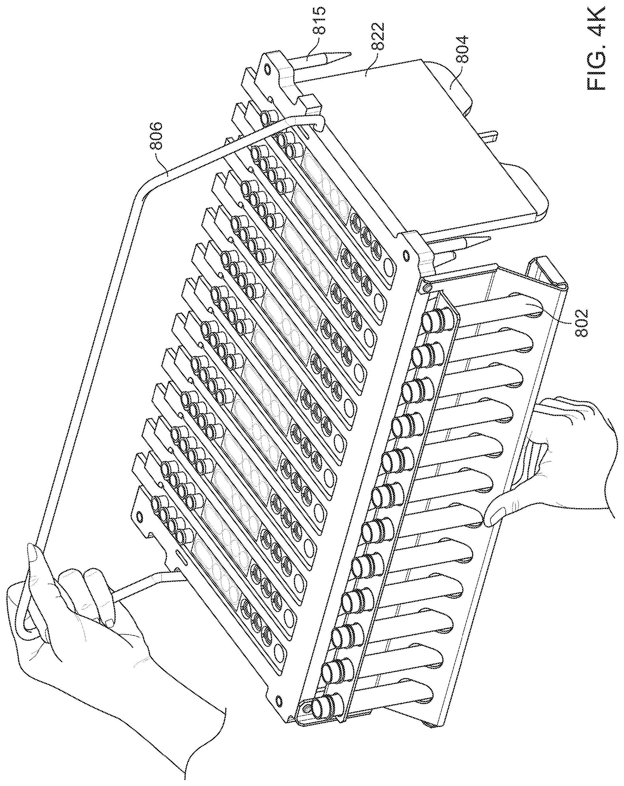
D00015
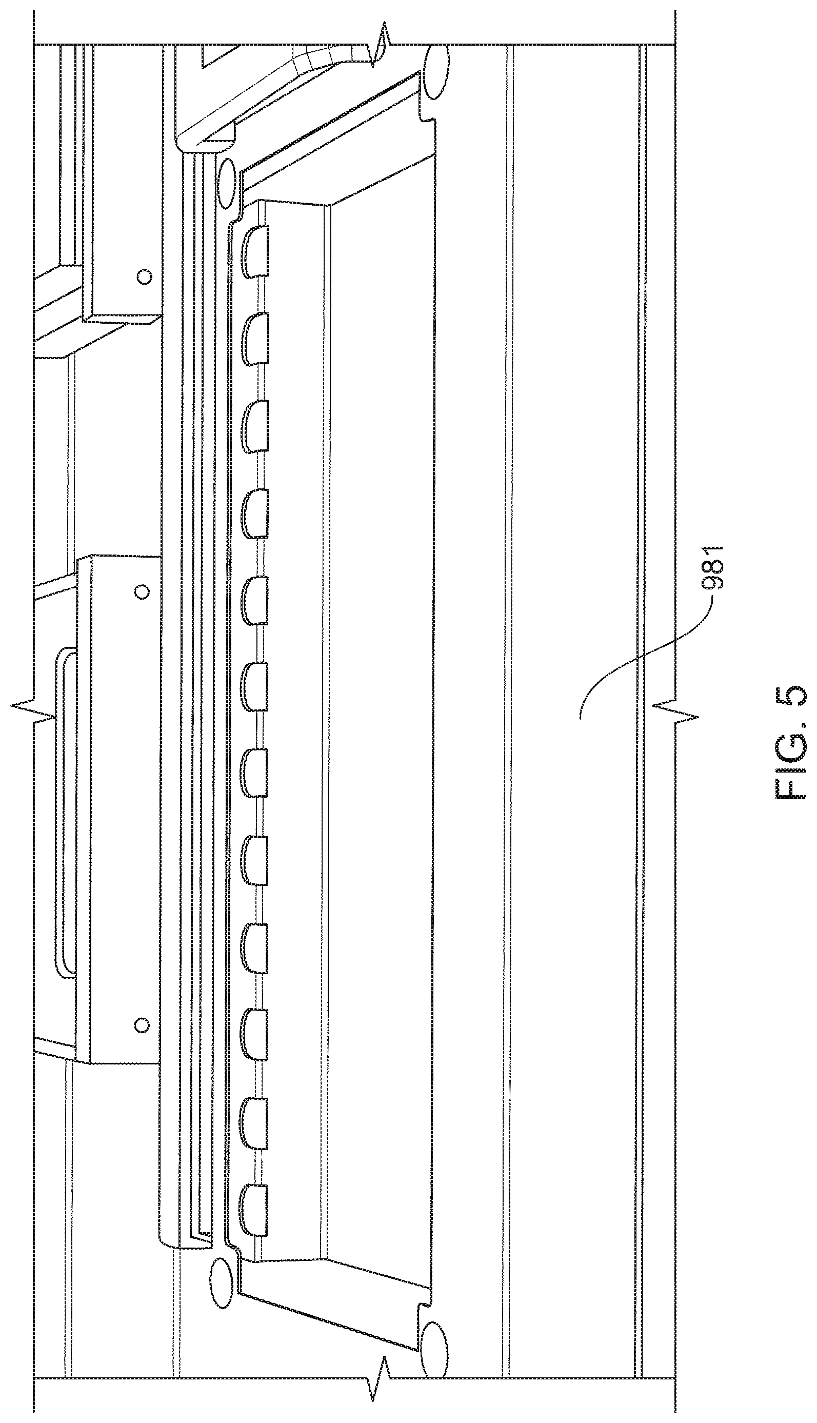
D00016
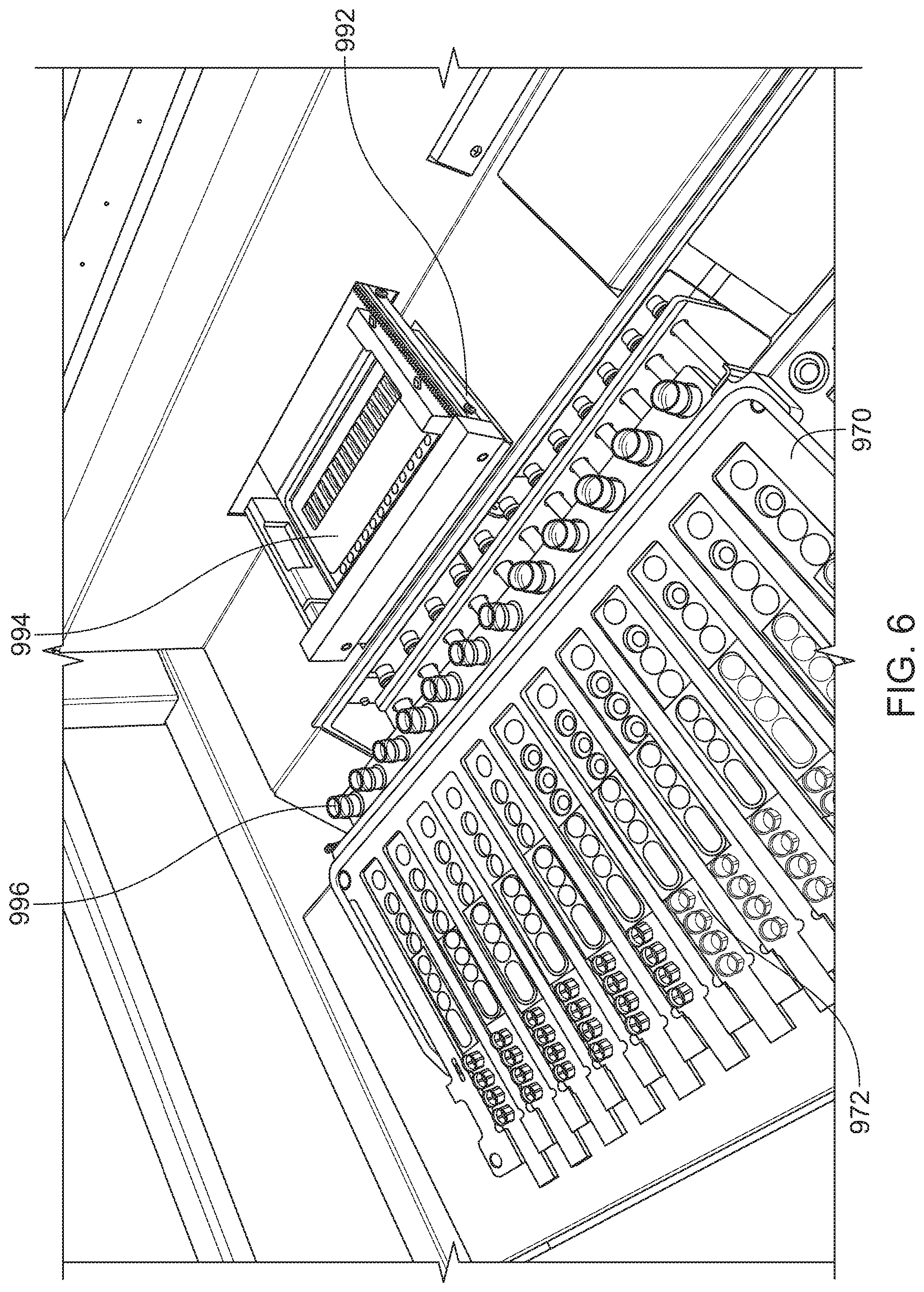
D00017

D00018
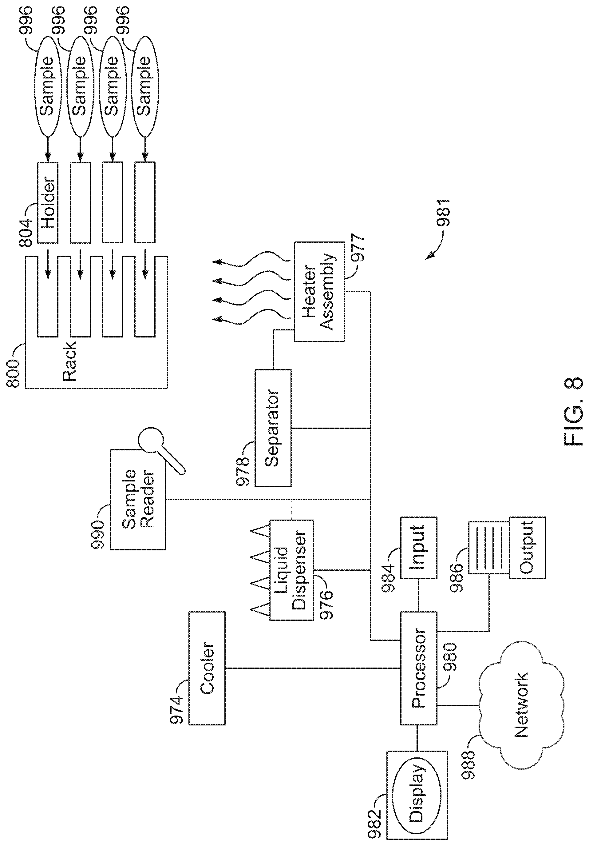
XML
uspto.report is an independent third-party trademark research tool that is not affiliated, endorsed, or sponsored by the United States Patent and Trademark Office (USPTO) or any other governmental organization. The information provided by uspto.report is based on publicly available data at the time of writing and is intended for informational purposes only.
While we strive to provide accurate and up-to-date information, we do not guarantee the accuracy, completeness, reliability, or suitability of the information displayed on this site. The use of this site is at your own risk. Any reliance you place on such information is therefore strictly at your own risk.
All official trademark data, including owner information, should be verified by visiting the official USPTO website at www.uspto.gov. This site is not intended to replace professional legal advice and should not be used as a substitute for consulting with a legal professional who is knowledgeable about trademark law.