Flexible expandable electrode and method of intraluminal delivery of pulsed power
Bakos , et al.
U.S. patent number 10,314,649 [Application Number 13/565,307] was granted by the patent office on 2019-06-11 for flexible expandable electrode and method of intraluminal delivery of pulsed power. This patent grant is currently assigned to Ethicon Endo-Surgery, Inc.. The grantee listed for this patent is Gregory J. Bakos, Gary L. Long, David N. Plescia, Peter K. Shires. Invention is credited to Gregory J. Bakos, Gary L. Long, David N. Plescia, Peter K. Shires.

View All Diagrams
| United States Patent | 10,314,649 |
| Bakos , et al. | June 11, 2019 |
Flexible expandable electrode and method of intraluminal delivery of pulsed power
Abstract
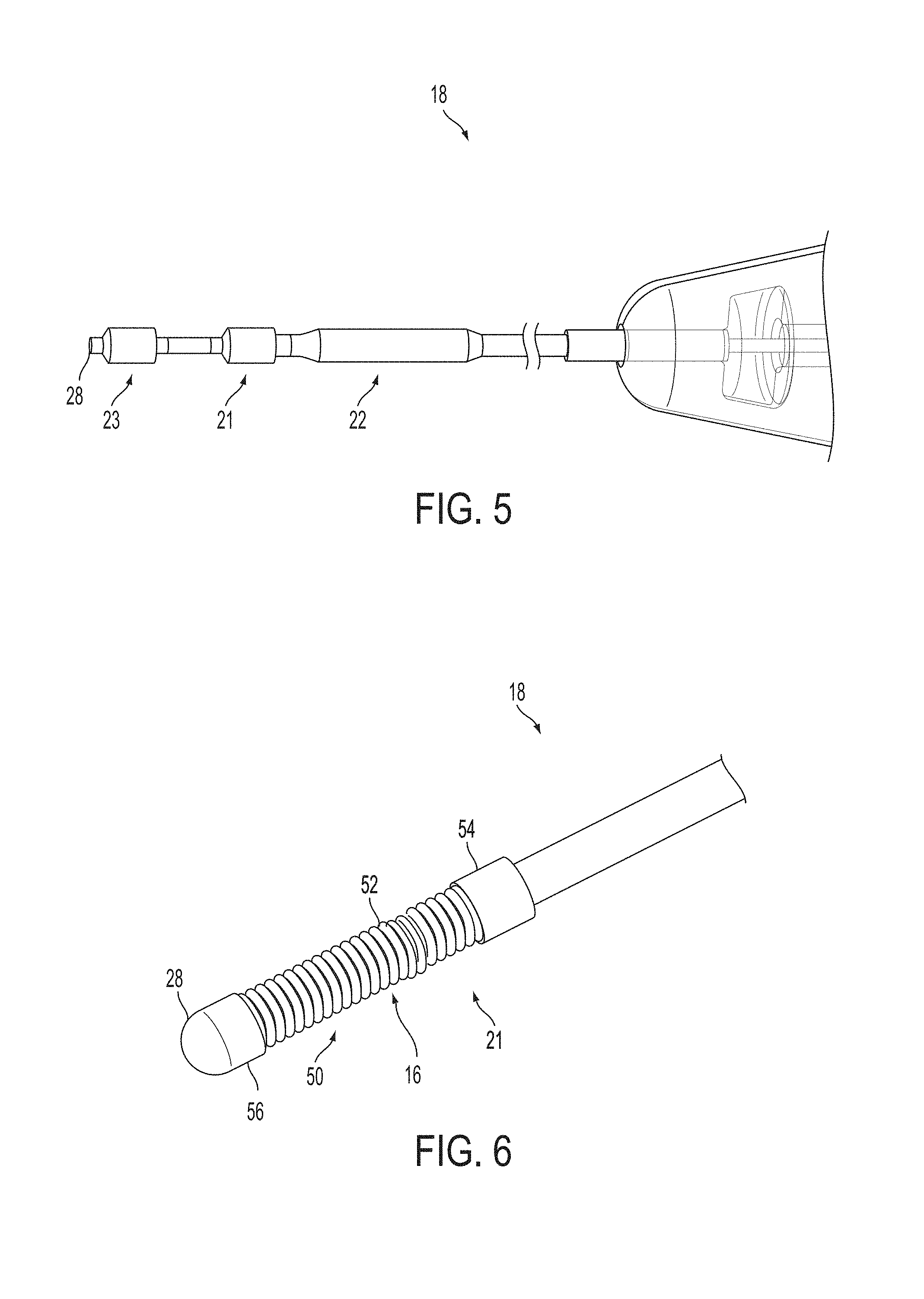
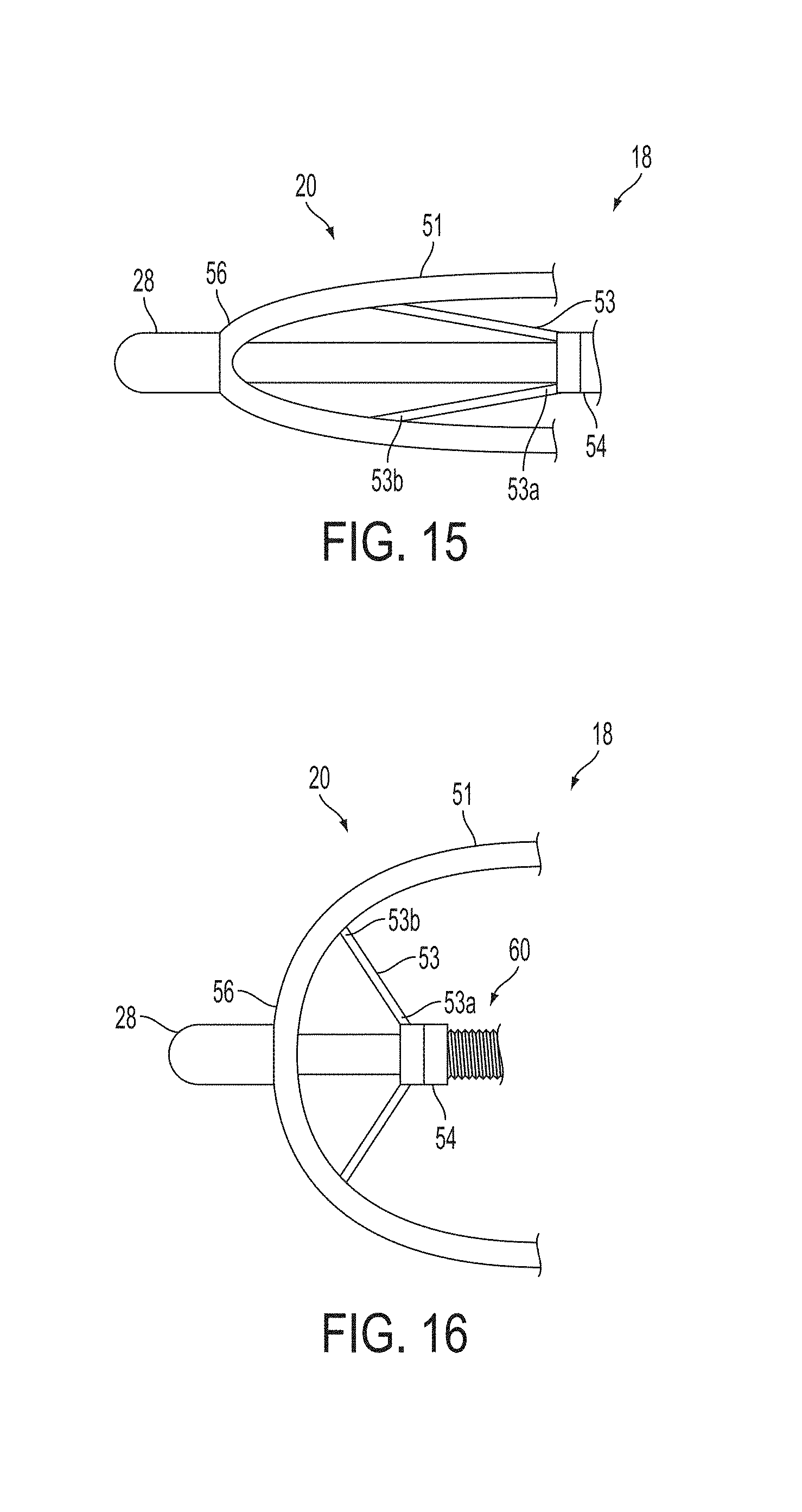
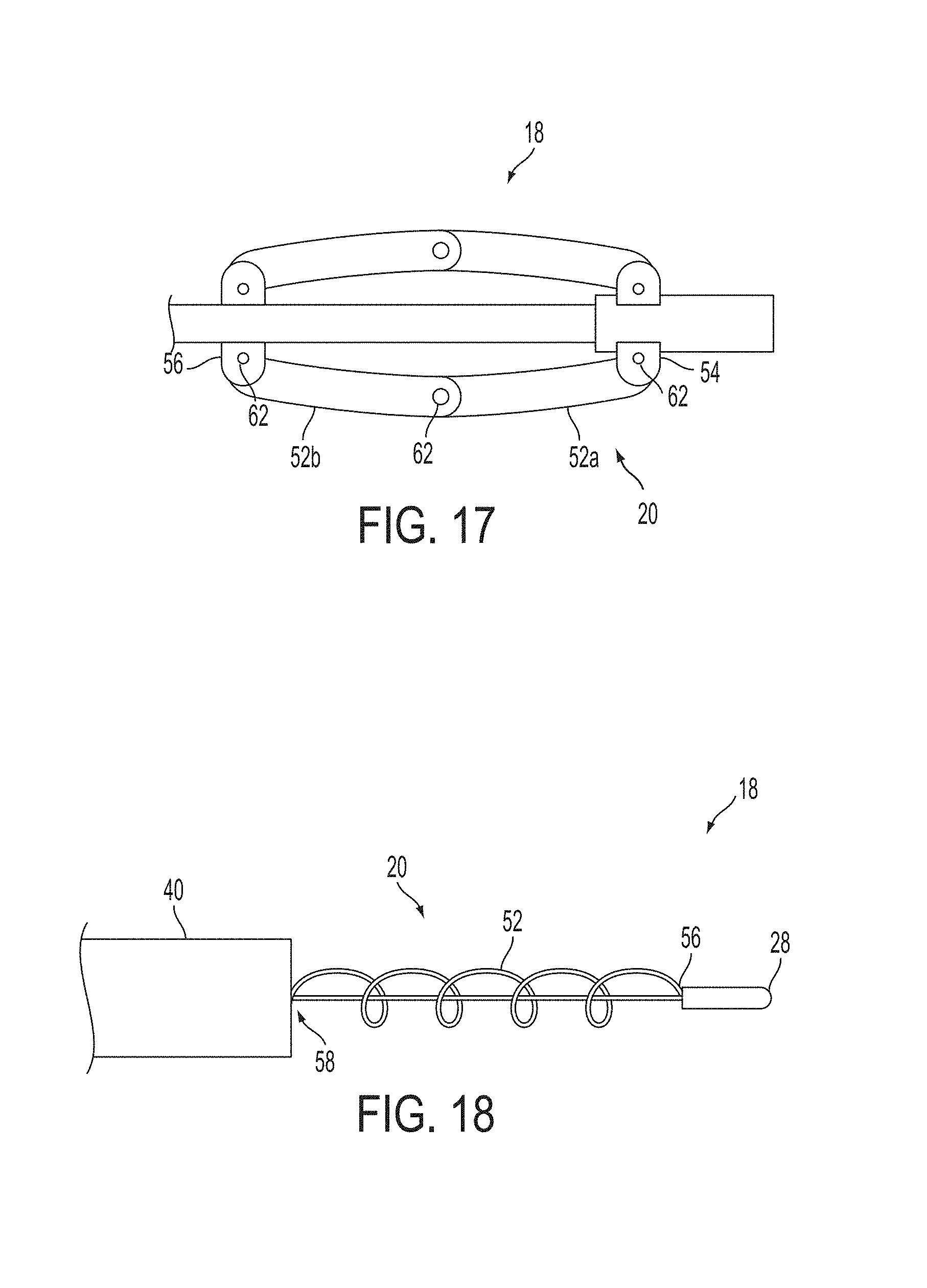
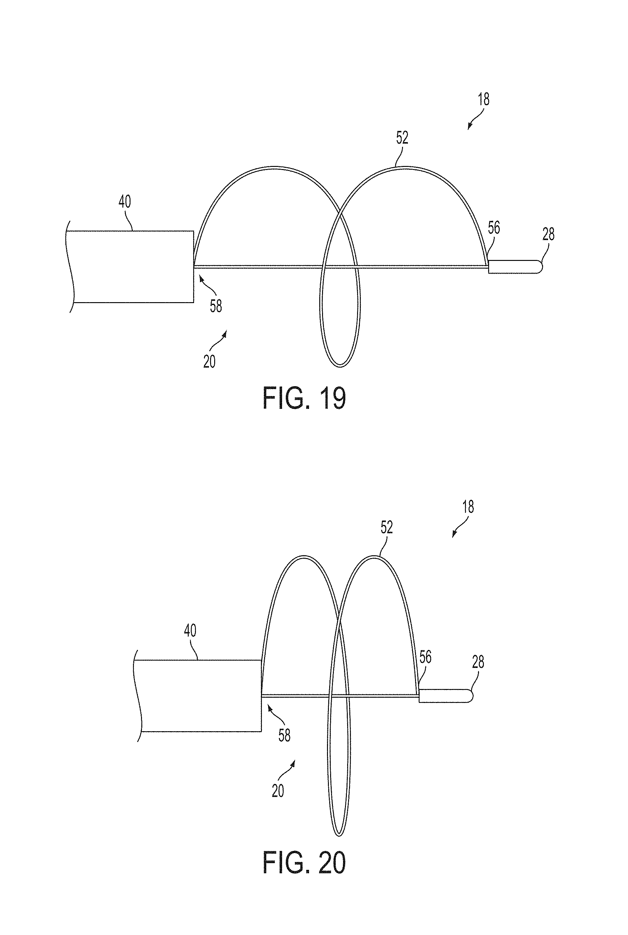
A surgical instrument, such as an electrical ablation device, includes an elongate member having therealong disposed a first electrode extending along an axis. A first expandable portion extends along the axis and defines a first perimeter of the first electrode and has an associated first diameter with respect to the axis. The first expandable portion includes a first framework selectively expandable to transition the first expandable portion from a contracted state to an expanded state. The first framework is selectively contractible to transition the first expandable portion from the expanded state to the contracted state. When the first framework is expanded, the first diameter is expanded and the first expandable portion is transitioned from the contracted state to the expanded state. When the first framework is contracted, the first diameter is contracted and the first expandable portion is transitioned from the expanded state to the contracted state.
| Inventors: | Bakos; Gregory J. (Mason, OH), Plescia; David N. (Mentor, OH), Long; Gary L. (Cincinnati, OH), Shires; Peter K. (Hamilton, OH) | ||||||||||
|---|---|---|---|---|---|---|---|---|---|---|---|
| Applicant: |
|
||||||||||
| Assignee: | Ethicon Endo-Surgery, Inc.
(Cincinnati, OH) |
||||||||||
| Family ID: | 48998695 | ||||||||||
| Appl. No.: | 13/565,307 | ||||||||||
| Filed: | August 2, 2012 |
Prior Publication Data
| Document Identifier | Publication Date | |
|---|---|---|
| US 20140039491 A1 | Feb 6, 2014 | |
| Current U.S. Class: | 1/1 |
| Current CPC Class: | A61B 18/1492 (20130101); A61B 2018/00613 (20130101); A61B 2018/00357 (20130101); A61B 2018/00202 (20130101); A61B 2017/00867 (20130101); A61B 2018/00267 (20130101); A61B 2018/00577 (20130101); A61B 2018/1475 (20130101); A61B 2018/1435 (20130101); A61B 2018/1465 (20130101); A61B 2018/00196 (20130101) |
| Current International Class: | A61B 18/18 (20060101); A61B 18/14 (20060101); A61B 17/00 (20060101); A61B 18/00 (20060101) |
References Cited [Referenced By]
U.S. Patent Documents
| 112794 | March 1871 | Felton |
| 645576 | March 1900 | Tesla |
| 649621 | May 1900 | Tesla |
| 787412 | April 1905 | Tesla |
| 1039354 | September 1912 | Bonadio |
| 1127948 | February 1915 | Wappler |
| 1482653 | February 1924 | Lilly |
| 1581706 | April 1926 | White |
| 1581707 | April 1926 | White |
| 1581708 | April 1926 | White |
| 1581709 | April 1926 | White |
| 1581710 | April 1926 | White |
| 1625602 | April 1927 | Gould et al. |
| 1916722 | July 1933 | Ende |
| 2028635 | January 1936 | Wappler |
| 2031682 | February 1936 | Wappler et al. |
| 2113246 | April 1938 | Wappler |
| 2137710 | November 1938 | Anderson |
| 2155365 | April 1939 | Rankin |
| 2191858 | February 1940 | Moore |
| 2196620 | April 1940 | Attarian |
| 2388137 | October 1945 | Graumlich |
| 2451077 | October 1948 | Emsig |
| 2493108 | January 1950 | Casey, Jr. |
| 2504152 | April 1950 | Riker et al. |
| 2938382 | May 1960 | De Graaf |
| 2952206 | September 1960 | Becksted |
| 3044461 | July 1962 | Murdock |
| 3069195 | December 1962 | Buck |
| 3070088 | December 1962 | Brahos |
| 3110956 | November 1963 | Fischer, Jr. |
| 3170471 | February 1965 | Schnitzer |
| 3435824 | April 1969 | Gamponia |
| 3470876 | October 1969 | Barchilon |
| 3481325 | December 1969 | Glassman |
| 3595239 | July 1971 | Petersen |
| 3669487 | June 1972 | Roberts et al. |
| 3746881 | July 1973 | Fitch et al. |
| 3799672 | March 1974 | Vurek |
| 3854473 | December 1974 | Matsuo |
| 3854743 | December 1974 | Hansen |
| 3929123 | December 1975 | Jamshidi |
| 3946740 | March 1976 | Bassett |
| 3948251 | April 1976 | Hosono |
| 3961632 | June 1976 | Moossun |
| 3965890 | June 1976 | Gauthier |
| 3994301 | November 1976 | Agris |
| 4011872 | March 1977 | Komiya |
| 4012812 | March 1977 | Black |
| 4043342 | August 1977 | Morrison, Jr. |
| 4071028 | January 1978 | Perkins |
| 4085743 | April 1978 | Yoon |
| 4164225 | August 1979 | Johnson et al. |
| 4170997 | October 1979 | Pinnow et al. |
| 4174715 | November 1979 | Hasson |
| 4178920 | December 1979 | Cawood, Jr. et al. |
| 4207873 | June 1980 | Kruy |
| 4235238 | November 1980 | Ogiu et al. |
| 4258716 | March 1981 | Sutherland |
| 4269174 | May 1981 | Adair |
| 4278077 | July 1981 | Mizumoto |
| 4281646 | August 1981 | Kinoshita |
| 4285344 | August 1981 | Marshall |
| 4311143 | January 1982 | Komiya |
| 4329980 | May 1982 | Terada |
| 4393872 | July 1983 | Reznik et al. |
| 4396021 | August 1983 | Baumgartner |
| 4396139 | August 1983 | Hall et al. |
| 4406656 | September 1983 | Hattler et al. |
| 4452246 | June 1984 | Bader et al. |
| 4461281 | July 1984 | Carson |
| 4491132 | January 1985 | Aikins |
| 4492232 | January 1985 | Green |
| 4527331 | July 1985 | Lasner et al. |
| 4527564 | July 1985 | Eguchi et al. |
| 4538594 | September 1985 | Boebel et al. |
| D281104 | October 1985 | Davison |
| 4569347 | February 1986 | Frisbie |
| 4580551 | April 1986 | Siegmund et al. |
| 4646722 | March 1987 | Silverstein et al. |
| 4649904 | March 1987 | Krauter et al. |
| 4653476 | March 1987 | Bonnet |
| 4655219 | April 1987 | Petruzzi |
| 4657016 | April 1987 | Garito et al. |
| 4657018 | April 1987 | Hakky |
| 4669470 | June 1987 | Brandfield |
| 4671477 | June 1987 | Cullen |
| 4677982 | July 1987 | Llinas et al. |
| 4685447 | August 1987 | Iversen et al. |
| 4711239 | December 1987 | Sorochenko et al. |
| 4711240 | December 1987 | Goldwasser et al. |
| 4712545 | December 1987 | Honkanen |
| 4721116 | January 1988 | Schintgen et al. |
| 4727600 | February 1988 | Avakian |
| 4733662 | March 1988 | DeSatnick et al. |
| D295894 | May 1988 | Sharkany et al. |
| 4742817 | May 1988 | Kawashima et al. |
| 4753223 | June 1988 | Bremer |
| 4763669 | August 1988 | Jaeger |
| 4770188 | September 1988 | Chikama |
| 4790624 | December 1988 | Van Hoye et al. |
| 4791707 | December 1988 | Tucker |
| 4796627 | January 1989 | Tucker |
| 4807593 | February 1989 | Ito |
| 4815450 | March 1989 | Patel |
| 4819620 | April 1989 | Okutsu |
| 4823794 | April 1989 | Pierce |
| 4829999 | May 1989 | Auth |
| 4836188 | June 1989 | Berry |
| 4846573 | July 1989 | Taylor et al. |
| 4867140 | September 1989 | Hovis et al. |
| 4869238 | September 1989 | Opie et al. |
| 4869459 | September 1989 | Bourne |
| 4873979 | October 1989 | Hanna |
| 4880015 | November 1989 | Nierman |
| 4904048 | February 1990 | Sogawa et al. |
| 4911148 | March 1990 | Sosnowski et al. |
| 4926860 | May 1990 | Stice et al. |
| 4934364 | June 1990 | Green |
| 4938214 | July 1990 | Specht et al. |
| 4950273 | August 1990 | Briggs |
| 4950285 | August 1990 | Wilk |
| 4953539 | September 1990 | Nakamura et al. |
| 4960133 | October 1990 | Hewson |
| 4977887 | December 1990 | Gouda |
| 4979496 | December 1990 | Komi |
| 4979950 | December 1990 | Transue et al. |
| 4984581 | January 1991 | Stice |
| 4990152 | February 1991 | Yoon |
| 4991565 | February 1991 | Takahashi et al. |
| 4994079 | February 1991 | Genese et al. |
| 5007917 | April 1991 | Evans |
| 5010876 | April 1991 | Henley et al. |
| 5015249 | May 1991 | Nakao et al. |
| 5020514 | June 1991 | Heckele |
| 5020535 | June 1991 | Parker et al. |
| 5025778 | June 1991 | Silverstein et al. |
| 5026379 | June 1991 | Yoon |
| 5033169 | July 1991 | Bindon |
| 5037433 | August 1991 | Wilk et al. |
| 5041129 | August 1991 | Hayhurst et al. |
| 5046513 | September 1991 | Gatturna et al. |
| 5049153 | September 1991 | Nakao et al. |
| 5050585 | September 1991 | Takahashi |
| 5052372 | October 1991 | Shapiro |
| 5065516 | November 1991 | Dulebohn |
| 5066295 | November 1991 | Kozak et al. |
| 5098378 | March 1992 | Piontek et al. |
| 5099827 | March 1992 | Melzer et al. |
| 5108421 | April 1992 | Fowler |
| 5123913 | June 1992 | Wilk et al. |
| 5123914 | June 1992 | Cope |
| 5133727 | July 1992 | Bales et al. |
| 5147374 | September 1992 | Fernandez |
| 5156609 | October 1992 | Nakao et al. |
| 5174300 | December 1992 | Bales et al. |
| 5176126 | January 1993 | Chikama |
| 5190050 | March 1993 | Nitzsche |
| 5190555 | March 1993 | Wetter et al. |
| 5192284 | March 1993 | Pleatman |
| 5192300 | March 1993 | Fowler |
| 5197963 | March 1993 | Parins |
| 5201752 | April 1993 | Brown et al. |
| 5201908 | April 1993 | Jones |
| 5203785 | April 1993 | Slater |
| 5203787 | April 1993 | Noblitt et al. |
| 5209747 | May 1993 | Knoepfler |
| 5217003 | June 1993 | Wilk |
| 5217453 | June 1993 | Wilk |
| 5219357 | June 1993 | Honkanen et al. |
| 5219358 | June 1993 | Bendel et al. |
| 5222362 | June 1993 | Maus et al. |
| 5222961 | June 1993 | Nakao et al. |
| 5222965 | June 1993 | Haughton |
| 5234437 | August 1993 | Sepetka |
| 5234453 | August 1993 | Smith et al. |
| 5235964 | August 1993 | Abenaim |
| 5242456 | September 1993 | Nash et al. |
| 5245460 | September 1993 | Allen et al. |
| 5246424 | September 1993 | Wilk |
| 5257999 | November 1993 | Slanetz, Jr. |
| 5259366 | November 1993 | Reydel et al. |
| 5263958 | November 1993 | deGuillebon et al. |
| 5273524 | December 1993 | Fox et al. |
| 5275607 | January 1994 | Lo et al. |
| 5275614 | January 1994 | Haber et al. |
| 5275616 | January 1994 | Fowler |
| 5284128 | February 1994 | Hart |
| 5284162 | February 1994 | Wilk |
| 5287845 | February 1994 | Faul et al. |
| 5287852 | February 1994 | Arkinstall |
| 5290299 | March 1994 | Fain et al. |
| 5290302 | March 1994 | Pericic |
| 5295977 | March 1994 | Cohen et al. |
| 5297536 | March 1994 | Wilk |
| 5297687 | March 1994 | Freed |
| 5301061 | April 1994 | Nakada et al. |
| 5312023 | May 1994 | Green et al. |
| 5312333 | May 1994 | Churinetz et al. |
| 5312351 | May 1994 | Gerrone |
| 5312416 | May 1994 | Spaeth et al. |
| 5312423 | May 1994 | Rosenbluth et al. |
| 5318589 | June 1994 | Lichtman |
| 5320636 | June 1994 | Slater |
| 5324261 | June 1994 | Amundson et al. |
| 5325845 | July 1994 | Adair |
| 5330471 | July 1994 | Eggers |
| 5330486 | July 1994 | Wilk |
| 5330488 | July 1994 | Goldrath |
| 5330496 | July 1994 | Alferness |
| 5330502 | July 1994 | Hassler et al. |
| 5331971 | July 1994 | Bales et al. |
| 5334168 | August 1994 | Hemmer |
| 5334198 | August 1994 | Hart et al. |
| 5336192 | August 1994 | Palestrant |
| 5336222 | August 1994 | Durgin, Jr. et al. |
| 5339805 | August 1994 | Parker |
| 5341815 | August 1994 | Cofone et al. |
| 5342396 | August 1994 | Cook |
| 5344428 | September 1994 | Griffiths |
| 5345927 | September 1994 | Bonutti |
| 5348259 | September 1994 | Blanco et al. |
| 5350391 | September 1994 | Iacovelli |
| 5352184 | October 1994 | Goldberg et al. |
| 5352222 | October 1994 | Rydell |
| 5354302 | October 1994 | Ko |
| 5354311 | October 1994 | Kambin et al. |
| 5356381 | October 1994 | Ensminger et al. |
| 5356408 | October 1994 | Rydell |
| 5360428 | November 1994 | Hutchinson, Jr. |
| 5364408 | November 1994 | Gordon |
| 5364410 | November 1994 | Failla et al. |
| 5366466 | November 1994 | Christian et al. |
| 5366467 | November 1994 | Lynch et al. |
| 5368605 | November 1994 | Miller, Jr. |
| 5368606 | November 1994 | Marlow et al. |
| 5370647 | December 1994 | Graber et al. |
| 5370679 | December 1994 | Atlee, III |
| 5374273 | December 1994 | Nakao et al. |
| 5374275 | December 1994 | Bradley et al. |
| 5374277 | December 1994 | Hassler |
| 5374953 | December 1994 | Sasaki et al. |
| 5376077 | December 1994 | Gomringer |
| 5377695 | January 1995 | An Haack |
| 5378234 | January 1995 | Hammerslag et al. |
| 5383877 | January 1995 | Clarke |
| 5383888 | January 1995 | Zvenyatsky et al. |
| 5386817 | February 1995 | Jones |
| 5387259 | February 1995 | Davidson |
| 5391174 | February 1995 | Weston |
| 5392789 | February 1995 | Slater et al. |
| 5395367 | March 1995 | Wilk |
| 5395381 | March 1995 | Green et al. |
| 5395386 | March 1995 | Slater |
| 5397332 | March 1995 | Kammerer et al. |
| 5401248 | March 1995 | Bencini |
| 5403311 | April 1995 | Abele et al. |
| 5403326 | April 1995 | Harrison et al. |
| 5403328 | April 1995 | Shallman |
| 5403342 | April 1995 | Tovey et al. |
| 5403348 | April 1995 | Bonutti |
| 5405073 | April 1995 | Porter |
| 5405359 | April 1995 | Pierce |
| 5409478 | April 1995 | Gerry et al. |
| 5417699 | May 1995 | Klein et al. |
| 5423821 | June 1995 | Pasque |
| 5431635 | July 1995 | Yoon |
| 5433721 | July 1995 | Hooven et al. |
| 5433735 | July 1995 | Zanakis et al. |
| 5439471 | August 1995 | Kerr |
| 5439478 | August 1995 | Palmer |
| 5441059 | August 1995 | Dannan |
| 5441494 | August 1995 | Ortiz |
| 5441498 | August 1995 | Perkins |
| 5441499 | August 1995 | Fritzsch |
| 5443463 | August 1995 | Stern et al. |
| 5445638 | August 1995 | Rydell et al. |
| 5445648 | August 1995 | Cook |
| 5449021 | September 1995 | Chikama |
| 5454827 | October 1995 | Aust et al. |
| 5456667 | October 1995 | Ham et al. |
| 5456684 | October 1995 | Schmidt et al. |
| 5458131 | October 1995 | Wilk |
| 5458583 | October 1995 | McNeely et al. |
| 5460168 | October 1995 | Masubuchi et al. |
| 5460629 | October 1995 | Shlain et al. |
| 5462561 | October 1995 | Voda |
| 5465731 | November 1995 | Bell et al. |
| 5467763 | November 1995 | McMahon et al. |
| 5468250 | November 1995 | Paraschac et al. |
| 5470308 | November 1995 | Edwards et al. |
| 5470320 | November 1995 | Tiefenbrun et al. |
| 5472441 | December 1995 | Edwards et al. |
| 5478347 | December 1995 | Aranyi |
| 5478352 | December 1995 | Fowler |
| 5480404 | January 1996 | Kammerer et al. |
| 5482029 | January 1996 | Sekiguchi et al. |
| 5482054 | January 1996 | Slater et al. |
| 5484451 | January 1996 | Akopov et al. |
| 5489256 | February 1996 | Adair |
| 5496347 | March 1996 | Hashiguchi et al. |
| 5499990 | March 1996 | Schulken et al. |
| 5499992 | March 1996 | Meade et al. |
| 5499997 | March 1996 | Sharpe et al. |
| 5500012 | March 1996 | Brucker et al. |
| 5501692 | March 1996 | Riza |
| 5503616 | April 1996 | Jones |
| 5505686 | April 1996 | Willis et al. |
| 5507755 | April 1996 | Gresl et al. |
| 5511564 | April 1996 | Wilk |
| 5514157 | May 1996 | Nicholas et al. |
| 5518501 | May 1996 | Oneda et al. |
| 5522829 | June 1996 | Michalos |
| 5522830 | June 1996 | Aranyi |
| 5527321 | June 1996 | Hinchliffe |
| 5533418 | July 1996 | Wu et al. |
| 5536234 | July 1996 | Newman |
| 5536248 | July 1996 | Weaver et al. |
| 5538509 | July 1996 | Dunlap et al. |
| 5540648 | July 1996 | Yoon |
| 5549637 | August 1996 | Crainich |
| 5554151 | September 1996 | Hinchliffe |
| 5555883 | September 1996 | Avitall |
| 5558133 | September 1996 | Bortoli et al. |
| 5562693 | October 1996 | Devlin et al. |
| 5569243 | October 1996 | Kortenbach et al. |
| 5569298 | October 1996 | Schnell |
| 5571090 | November 1996 | Sherts |
| 5573540 | November 1996 | Yoon |
| 5578030 | November 1996 | Levin |
| 5582611 | December 1996 | Tsuruta et al. |
| 5582617 | December 1996 | Klieman et al. |
| 5584845 | December 1996 | Hart |
| 5590660 | January 1997 | MacAulay et al. |
| 5591179 | January 1997 | Edelstein |
| 5591205 | January 1997 | Fowler |
| 5593420 | January 1997 | Eubanks, Jr. et al. |
| 5595562 | January 1997 | Grier |
| 5597378 | January 1997 | Jervis |
| 5601573 | February 1997 | Fogelberg et al. |
| 5601574 | February 1997 | Stefanchik et al. |
| 5601588 | February 1997 | Tonomura et al. |
| 5601602 | February 1997 | Fowler |
| 5604531 | February 1997 | Iddan et al. |
| 5607386 | March 1997 | Flam |
| 5607389 | March 1997 | Edwards et al. |
| 5607406 | March 1997 | Hernandez et al. |
| 5607450 | March 1997 | Zvenyatsky et al. |
| 5609601 | March 1997 | Kolesa et al. |
| 5613975 | March 1997 | Christy |
| 5613977 | March 1997 | Weber et al. |
| 5614943 | March 1997 | Nakamura et al. |
| 5616117 | April 1997 | Dinkier et al. |
| 5618303 | April 1997 | Marlow et al. |
| 5620415 | April 1997 | Lucey et al. |
| 5624399 | April 1997 | Ackerman |
| 5624431 | April 1997 | Gerry et al. |
| 5626578 | May 1997 | Tihon |
| 5626587 | May 1997 | Bishop et al. |
| 5628732 | May 1997 | Antoon, Jr. et al. |
| 5630782 | May 1997 | Adair |
| 5630795 | May 1997 | Kuramoto et al. |
| 5643283 | July 1997 | Younker |
| 5643292 | July 1997 | Hart |
| 5643294 | July 1997 | Tovey et al. |
| 5644798 | July 1997 | Shah |
| 5645083 | July 1997 | Essig et al. |
| 5645519 | July 1997 | Lee et al. |
| 5645565 | July 1997 | Rudd et al. |
| 5649372 | July 1997 | Souza |
| 5653677 | August 1997 | Okada et al. |
| 5653690 | August 1997 | Booth et al. |
| 5653722 | August 1997 | Kieturakis |
| 5657755 | August 1997 | Desai |
| 5662621 | September 1997 | Lafontaine |
| 5662663 | September 1997 | Shallman |
| 5667527 | September 1997 | Cook |
| 5669875 | September 1997 | van Eerdenburg |
| 5681276 | October 1997 | Lundquist |
| 5681279 | October 1997 | Roper et al. |
| 5681324 | October 1997 | Kammerer et al. |
| 5681330 | October 1997 | Hughett et al. |
| 5685820 | November 1997 | Riek et al. |
| 5690606 | November 1997 | Slotman |
| 5690656 | November 1997 | Cope et al. |
| 5690660 | November 1997 | Kauker et al. |
| 5695448 | December 1997 | Kimura et al. |
| 5695505 | December 1997 | Yoon |
| 5695511 | December 1997 | Cano et al. |
| 5700275 | December 1997 | Bell et al. |
| 5702438 | December 1997 | Avitall |
| 5704892 | January 1998 | Adair |
| 5709708 | January 1998 | Thal |
| 5711921 | January 1998 | Langford |
| 5716326 | February 1998 | Dannan |
| 5716375 | February 1998 | Fowler |
| 5725542 | March 1998 | Yoon |
| 5728094 | March 1998 | Edwards |
| 5730740 | March 1998 | Wales et al. |
| 5735849 | April 1998 | Baden et al. |
| 5741234 | April 1998 | Aboul-Hosn |
| 5741278 | April 1998 | Stevens |
| 5741285 | April 1998 | McBrayer et al. |
| 5741429 | April 1998 | Donadio, III et al. |
| 5743456 | April 1998 | Jones et al. |
| 5746759 | May 1998 | Meade et al. |
| 5749826 | May 1998 | Faulkner |
| 5749881 | May 1998 | Sackier et al. |
| 5749889 | May 1998 | Bacich et al. |
| 5752951 | May 1998 | Yanik |
| 5755731 | May 1998 | Grinberg |
| 5759150 | June 1998 | Konou et al. |
| 5759151 | June 1998 | Sturges |
| 5762604 | June 1998 | Kieturakis |
| 5766167 | June 1998 | Eggers et al. |
| 5766170 | June 1998 | Eggers |
| 5766205 | June 1998 | Zvenyatsky et al. |
| 5769849 | June 1998 | Eggers |
| 5776188 | July 1998 | Shepherd et al. |
| 5779701 | July 1998 | McBrayer et al. |
| 5779716 | July 1998 | Cano et al. |
| 5779720 | July 1998 | Walder-Utz et al. |
| 5779727 | July 1998 | Orejola |
| 5782859 | July 1998 | Nicholas et al. |
| 5782861 | July 1998 | Cragg et al. |
| 5782866 | July 1998 | Wenstrom, Jr. |
| 5791022 | August 1998 | Bohman |
| 5792113 | August 1998 | Kramer et al. |
| 5792153 | August 1998 | Swain et al. |
| 5792165 | August 1998 | Klieman et al. |
| 5797835 | August 1998 | Green |
| 5797928 | August 1998 | Kogasaka |
| 5797939 | August 1998 | Yoon |
| 5797941 | August 1998 | Schulze et al. |
| 5797959 | August 1998 | Castro et al. |
| 5797960 | August 1998 | Stevens et al. |
| 5800449 | September 1998 | Wales |
| 5800451 | September 1998 | Buess et al. |
| 5803903 | September 1998 | Athas et al. |
| 5807395 | September 1998 | Mulier et al. |
| 5808665 | September 1998 | Green |
| 5810805 | September 1998 | Sutcu et al. |
| 5810806 | September 1998 | Ritchart et al. |
| 5810849 | September 1998 | Kontos |
| 5810865 | September 1998 | Koscher et al. |
| 5810876 | September 1998 | Kelleher |
| 5810877 | September 1998 | Roth et al. |
| 5813976 | September 1998 | Filipi et al. |
| 5814026 | September 1998 | Yoon |
| 5814058 | September 1998 | Carlson et al. |
| 5817061 | October 1998 | Goodwin et al. |
| 5817107 | October 1998 | Schaller |
| 5817119 | October 1998 | Klieman et al. |
| 5818527 | October 1998 | Yamaguchi et al. |
| 5819736 | October 1998 | Avny et al. |
| 5823947 | October 1998 | Yoon et al. |
| 5824071 | October 1998 | Nelson et al. |
| 5827190 | October 1998 | Palcic et al. |
| 5827276 | October 1998 | LeVeen et al. |
| 5827281 | October 1998 | Levin |
| 5827299 | October 1998 | Thomason et al. |
| 5827323 | October 1998 | Klieman et al. |
| 5830221 | November 1998 | Stein et al. |
| 5830231 | November 1998 | Geiges, Jr. |
| 5833603 | November 1998 | Kovacs et al. |
| 5833700 | November 1998 | Fogelberg et al. |
| 5833703 | November 1998 | Manushakian |
| 5833715 | November 1998 | Vachon et al. |
| 5836960 | November 1998 | Kolesa et al. |
| 5843017 | December 1998 | Yoon |
| 5843097 | December 1998 | Mayenberger et al. |
| 5843121 | December 1998 | Yoon |
| 5849022 | December 1998 | Sakashita et al. |
| 5853374 | December 1998 | Hart et al. |
| 5855569 | January 1999 | Komi |
| 5855585 | January 1999 | Kontos |
| 5860913 | January 1999 | Yamaya et al. |
| 5860995 | January 1999 | Berkelaar |
| 5868762 | February 1999 | Cragg et al. |
| 5873849 | February 1999 | Bernard |
| 5876411 | March 1999 | Kontos |
| 5882331 | March 1999 | Sasaki |
| 5882344 | March 1999 | Stouder, Jr. |
| 5893846 | April 1999 | Bales et al. |
| 5893874 | April 1999 | Bourque et al. |
| 5893875 | April 1999 | O'Connor et al. |
| 5897487 | April 1999 | Ouchi |
| 5899919 | May 1999 | Eubanks, Jr. et al. |
| 5902238 | May 1999 | Golden et al. |
| 5902254 | May 1999 | Magram |
| 5904702 | May 1999 | Ek et al. |
| 5906625 | May 1999 | Bito et al. |
| 5908420 | June 1999 | Parins et al. |
| 5908429 | June 1999 | Yoon |
| 5911737 | June 1999 | Lee et al. |
| 5916146 | June 1999 | Allotta et al. |
| 5916147 | June 1999 | Boury |
| 5919207 | July 1999 | Taheri |
| 5921892 | July 1999 | Easton |
| 5921993 | July 1999 | Yoon |
| 5921997 | July 1999 | Fogelberg et al. |
| 5922008 | July 1999 | Gimpelson |
| 5925052 | July 1999 | Simmons |
| 5928255 | July 1999 | Meade et al. |
| 5928266 | July 1999 | Kontos |
| 5936536 | August 1999 | Morris |
| 5938661 | August 1999 | Hahnen |
| 5941815 | August 1999 | Chang |
| 5944718 | August 1999 | Austin et al. |
| 5951547 | September 1999 | Gough et al. |
| 5951549 | September 1999 | Richardson et al. |
| 5954720 | September 1999 | Wilson et al. |
| 5954731 | September 1999 | Yoon |
| 5957936 | September 1999 | Yoon et al. |
| 5957943 | September 1999 | Vaitekunas |
| 5957953 | September 1999 | DiPoto et al. |
| 5964782 | October 1999 | Lafontaine et al. |
| 5970581 | October 1999 | Chadwick et al. |
| 5971995 | October 1999 | Rousseau |
| 5972002 | October 1999 | Bark et al. |
| 5976074 | November 1999 | Moriyama |
| 5976075 | November 1999 | Beane et al. |
| 5976130 | November 1999 | McBrayer et al. |
| 5976131 | November 1999 | Guglielmi et al. |
| 5980539 | November 1999 | Kontos |
| 5980556 | November 1999 | Giordano et al. |
| 5984933 | November 1999 | Yoon |
| 5984938 | November 1999 | Yoon |
| 5984939 | November 1999 | Yoon |
| 5984950 | November 1999 | Cragg et al. |
| 5989182 | November 1999 | Hori et al. |
| 5993447 | November 1999 | Blewett et al. |
| 5993474 | November 1999 | Ouchi |
| 5995875 | November 1999 | Blewett et al. |
| 5997555 | December 1999 | Kontos |
| 6001120 | December 1999 | Levin |
| 6004269 | December 1999 | Crowley et al. |
| 6004330 | December 1999 | Middleman et al. |
| 6007566 | December 1999 | Wenstrom, Jr. |
| 6010515 | January 2000 | Swain et al. |
| 6012494 | January 2000 | Balazs |
| 6016452 | January 2000 | Kasevich |
| 6017356 | January 2000 | Frederick et al. |
| 6019770 | February 2000 | Christoudias |
| 6024708 | February 2000 | Bales et al. |
| 6024747 | February 2000 | Kontos |
| 6027522 | February 2000 | Palmer |
| 6030365 | February 2000 | Laufer |
| 6030384 | February 2000 | Nezhat |
| 6030634 | February 2000 | Wu et al. |
| 6033399 | March 2000 | Gines |
| 6033401 | March 2000 | Edwards et al. |
| 6036640 | March 2000 | Corace et al. |
| 6036685 | March 2000 | Mueller |
| 6050992 | April 2000 | Nichols |
| 6053927 | April 2000 | Hamas |
| 6053937 | April 2000 | Edwards et al. |
| 6059719 | May 2000 | Yamamoto et al. |
| 6066160 | May 2000 | Colvin et al. |
| 6068603 | May 2000 | Suzuki |
| 6068629 | May 2000 | Haissaguerre et al. |
| 6071233 | June 2000 | Ishikawa et al. |
| 6074408 | June 2000 | Freeman |
| 6086530 | July 2000 | Mack |
| 6086600 | July 2000 | Kortenbach |
| 6090105 | July 2000 | Zepeda et al. |
| 6090108 | July 2000 | McBrayer et al. |
| 6090129 | July 2000 | Ouchi |
| 6096046 | August 2000 | Weiss |
| 6102909 | August 2000 | Chen et al. |
| 6102926 | August 2000 | Tartaglia et al. |
| 6106473 | August 2000 | Violante et al. |
| 6106521 | August 2000 | Blewett et al. |
| 6109852 | August 2000 | Shahinpoor et al. |
| 6110154 | August 2000 | Shimomura et al. |
| 6110183 | August 2000 | Cope |
| 6113593 | September 2000 | Tu et al. |
| 6117144 | September 2000 | Nobles et al. |
| 6117158 | September 2000 | Measamer et al. |
| 6123718 | September 2000 | Tu et al. |
| 6131790 | October 2000 | Piraka |
| 6139555 | October 2000 | Hart et al. |
| 6141037 | October 2000 | Upton et al. |
| 6146391 | November 2000 | Cigaina |
| 6148222 | November 2000 | Ramsey, III |
| 6149653 | November 2000 | Deslauriers |
| 6149662 | November 2000 | Pugliesi et al. |
| 6152871 | November 2000 | Foley et al. |
| 6152920 | November 2000 | Thompson et al. |
| 6156006 | December 2000 | Brosens et al. |
| 6159200 | December 2000 | Verdura et al. |
| 6165175 | December 2000 | Wampler et al. |
| 6165184 | December 2000 | Verdura et al. |
| 6168570 | January 2001 | Ferrera |
| 6168605 | January 2001 | Measamer et al. |
| 6169269 | January 2001 | Maynard |
| 6170130 | January 2001 | Hamilton et al. |
| 6173872 | January 2001 | Cohen |
| 6179776 | January 2001 | Adams et al. |
| 6179832 | January 2001 | Jones et al. |
| 6179837 | January 2001 | Hooven |
| 6183420 | February 2001 | Douk et al. |
| 6190353 | February 2001 | Makower et al. |
| 6190383 | February 2001 | Schmaltz et al. |
| 6190384 | February 2001 | Ouchi |
| 6190399 | February 2001 | Palmer et al. |
| 6203533 | March 2001 | Ouchi |
| 6206872 | March 2001 | Lafond et al. |
| 6206877 | March 2001 | Kese et al. |
| 6206904 | March 2001 | Ouchi |
| 6210409 | April 2001 | Ellman et al. |
| 6214007 | April 2001 | Anderson |
| 6214028 | April 2001 | Yoon et al. |
| 6216043 | April 2001 | Swanson et al. |
| 6228096 | May 2001 | Marchand |
| 6231506 | May 2001 | Hu et al. |
| 6234958 | May 2001 | Snoke et al. |
| 6240312 | May 2001 | Alfano et al. |
| 6245079 | June 2001 | Nobles et al. |
| 6246914 | June 2001 | de la Rama et al. |
| 6248124 | June 2001 | Pedros et al. |
| 6258064 | July 2001 | Smith et al. |
| 6261242 | July 2001 | Roberts et al. |
| 6264664 | July 2001 | Avellanet |
| 6270497 | August 2001 | Sekino et al. |
| 6270505 | August 2001 | Yoshida et al. |
| 6277136 | August 2001 | Bonutti |
| 6283963 | September 2001 | Regula |
| 6287304 | September 2001 | Eggers et al. |
| 6293909 | September 2001 | Chu et al. |
| 6293952 | September 2001 | Brosens et al. |
| 6296630 | October 2001 | Altman et al. |
| 6314963 | November 2001 | Vaska et al. |
| 6322578 | November 2001 | Houle et al. |
| 6325534 | December 2001 | Hawley et al. |
| 6326177 | December 2001 | Schoenbach et al. |
| 6328730 | December 2001 | Harkrider, Jr. |
| 6350267 | February 2002 | Stefanchik |
| 6350269 | February 2002 | Shipp et al. |
| 6350278 | February 2002 | Lenker et al. |
| 6352503 | March 2002 | Matsui et al. |
| 6352541 | March 2002 | Kienzle et al. |
| 6352543 | March 2002 | Cole |
| 6355013 | March 2002 | van Muiden |
| 6355035 | March 2002 | Manushakian |
| 6361534 | March 2002 | Chen et al. |
| 6364879 | April 2002 | Chen et al. |
| 6368340 | April 2002 | Malecki et al. |
| 6371956 | April 2002 | Wilson et al. |
| 6379366 | April 2002 | Fleischman et al. |
| 6383195 | May 2002 | Richard |
| 6383197 | May 2002 | Conlon et al. |
| 6387671 | May 2002 | Rubinsky et al. |
| 6391029 | May 2002 | Hooven et al. |
| 6398708 | June 2002 | Hastings et al. |
| 6402735 | June 2002 | Langevin |
| 6402746 | June 2002 | Whayne et al. |
| 6406440 | June 2002 | Stefanchik |
| 6409727 | June 2002 | Bales et al. |
| 6409733 | June 2002 | Conlon et al. |
| 6419639 | July 2002 | Walther et al. |
| 6419641 | July 2002 | Mark et al. |
| 6427089 | July 2002 | Knowlton |
| 6431500 | August 2002 | Jacobs et al. |
| 6436107 | August 2002 | Wang et al. |
| 6443970 | September 2002 | Schulze et al. |
| 6443988 | September 2002 | Felt et al. |
| 6447444 | September 2002 | Avni et al. |
| 6447511 | September 2002 | Slater |
| 6447523 | September 2002 | Middleman et al. |
| 6454783 | September 2002 | Piskun |
| 6454785 | September 2002 | De Hoyos Garza |
| 6458074 | October 2002 | Matsui et al. |
| 6458076 | October 2002 | Pruitt |
| 6464701 | October 2002 | Hooven et al. |
| 6464702 | October 2002 | Schulze et al. |
| 6470218 | October 2002 | Behl |
| 6475104 | November 2002 | Lutz et al. |
| 6485411 | November 2002 | Konstorum et al. |
| 6489745 | December 2002 | Koreis |
| 6491626 | December 2002 | Stone et al. |
| 6491627 | December 2002 | Komi |
| 6491691 | December 2002 | Morley et al. |
| 6493590 | December 2002 | Wessman et al. |
| 6494893 | December 2002 | Dubrul et al. |
| 6500176 | December 2002 | Truckai et al. |
| 6503192 | January 2003 | Ouchi |
| 6506190 | January 2003 | Walshe |
| 6508827 | January 2003 | Manhes |
| 6514239 | February 2003 | Shimmura et al. |
| 6517534 | February 2003 | McGovern et al. |
| 6520954 | February 2003 | Ouchi |
| 6526320 | February 2003 | Mitchell |
| 6527753 | March 2003 | Sekine et al. |
| 6527782 | March 2003 | Hogg et al. |
| 6530880 | March 2003 | Pagliuca |
| 6530922 | March 2003 | Cosman et al. |
| 6535764 | March 2003 | Imran et al. |
| 6537200 | March 2003 | Leysieffer et al. |
| 6543456 | April 2003 | Freeman |
| 6551270 | April 2003 | Bimbo et al. |
| 6551356 | April 2003 | Rousseau |
| 6554766 | April 2003 | Maeda et al. |
| 6554823 | April 2003 | Palmer et al. |
| 6554829 | April 2003 | Schulze et al. |
| 6558384 | May 2003 | Mayenberger |
| 6562034 | May 2003 | Edwards et al. |
| 6562035 | May 2003 | Levin |
| 6562052 | May 2003 | Nobles et al. |
| 6569120 | May 2003 | Green et al. |
| 6569159 | May 2003 | Edwards et al. |
| 6572629 | June 2003 | Kalloo et al. |
| 6572635 | June 2003 | Bonutti |
| 6575988 | June 2003 | Rousseau |
| 6579311 | June 2003 | Makower |
| 6581889 | June 2003 | Carpenter et al. |
| 6585642 | July 2003 | Christopher |
| 6585717 | July 2003 | Wittenberger et al. |
| 6587750 | July 2003 | Gerbi et al. |
| 6592559 | July 2003 | Pakter et al. |
| 6592603 | July 2003 | Lasner |
| 6594971 | July 2003 | Addy et al. |
| 6602262 | August 2003 | Griego et al. |
| 6605105 | August 2003 | Cuschieri et al. |
| 6610072 | August 2003 | Christy et al. |
| 6610074 | August 2003 | Santilli |
| 6613038 | September 2003 | Bonutti et al. |
| 6613068 | September 2003 | Ouchi |
| 6616632 | September 2003 | Sharp et al. |
| 6620193 | September 2003 | Lau et al. |
| 6623448 | September 2003 | Slater |
| 6626919 | September 2003 | Swanstrom |
| 6632171 | October 2003 | Iddan et al. |
| 6632229 | October 2003 | Yamanouchi |
| 6632234 | October 2003 | Kieturakis et al. |
| 6638275 | October 2003 | McGaffigan et al. |
| 6638286 | October 2003 | Burbank et al. |
| 6645225 | November 2003 | Atkinson |
| 6652518 | November 2003 | Wellman et al. |
| 6652521 | November 2003 | Schulze |
| 6652545 | November 2003 | Shipp et al. |
| 6652551 | November 2003 | Heiss |
| 6656194 | December 2003 | Gannoe et al. |
| 6663641 | December 2003 | Kovac et al. |
| 6663655 | December 2003 | Ginn et al. |
| 6666854 | December 2003 | Lange |
| 6672338 | January 2004 | Esashi et al. |
| 6673058 | January 2004 | Snow |
| 6673070 | January 2004 | Edwards et al. |
| 6673087 | January 2004 | Chang et al. |
| 6673092 | January 2004 | Bacher |
| 6676685 | January 2004 | Pedros et al. |
| 6679882 | January 2004 | Kornerup |
| 6684938 | February 2004 | Tsujita et al. |
| 6685628 | February 2004 | Vu |
| 6685724 | February 2004 | Haluck |
| 6692445 | February 2004 | Roberts et al. |
| 6692462 | February 2004 | Mackenzie et al. |
| 6692493 | February 2004 | McGovern et al. |
| 6695867 | February 2004 | Ginn et al. |
| 6699180 | March 2004 | Kobayashi |
| 6699256 | March 2004 | Logan et al. |
| 6699263 | March 2004 | Cope |
| 6706018 | March 2004 | Westlund et al. |
| 6708066 | March 2004 | Herbst et al. |
| 6709188 | March 2004 | Ushimaru |
| 6709445 | March 2004 | Boebel et al. |
| 6716226 | April 2004 | Sixto, Jr. et al. |
| 6731875 | May 2004 | Kartalopoulos |
| 6736822 | May 2004 | McClellan et al. |
| 6740030 | May 2004 | Martone et al. |
| 6740082 | May 2004 | Shadduck |
| 6743166 | June 2004 | Berci et al. |
| 6743226 | June 2004 | Cosman et al. |
| 6743239 | June 2004 | Kuehn et al. |
| 6743240 | June 2004 | Smith et al. |
| 6749560 | June 2004 | Konstorum et al. |
| 6749609 | June 2004 | Lunsford et al. |
| 6752768 | June 2004 | Burdorff et al. |
| 6752811 | June 2004 | Chu et al. |
| 6752822 | June 2004 | Jespersen |
| 6758857 | July 2004 | Cioanta et al. |
| 6761685 | July 2004 | Adams et al. |
| 6761718 | July 2004 | Madsen |
| 6761722 | July 2004 | Cole et al. |
| 6767356 | July 2004 | Kanner et al. |
| 6773434 | August 2004 | Ciarrocca |
| 6776165 | August 2004 | Jin |
| 6776787 | August 2004 | Phung et al. |
| 6780151 | August 2004 | Grabover et al. |
| 6780352 | August 2004 | Jacobson |
| 6783491 | August 2004 | Saadat et al. |
| 6786382 | September 2004 | Hoffman |
| 6786864 | September 2004 | Matsuura et al. |
| 6786905 | September 2004 | Swanson et al. |
| 6788977 | September 2004 | Fenn et al. |
| 6790173 | September 2004 | Saadat et al. |
| 6790217 | September 2004 | Schulze et al. |
| 6795728 | September 2004 | Chornenky et al. |
| 6800056 | October 2004 | Tartaglia et al. |
| 6808491 | October 2004 | Kortenbach et al. |
| 6817974 | November 2004 | Cooper et al. |
| 6818007 | November 2004 | Dampney et al. |
| 6821285 | November 2004 | Laufer et al. |
| 6824548 | November 2004 | Smith et al. |
| 6830545 | December 2004 | Bendall |
| 6835200 | December 2004 | Laufer et al. |
| 6836688 | December 2004 | Ingle et al. |
| 6837847 | January 2005 | Ewers et al. |
| 6840246 | January 2005 | Downing |
| 6840938 | January 2005 | Morley et al. |
| 6843794 | January 2005 | Sixto, Jr. et al. |
| 6861250 | March 2005 | Cole et al. |
| 6866627 | March 2005 | Nozue |
| 6866628 | March 2005 | Goodman et al. |
| 6869394 | March 2005 | Ishibiki |
| 6878106 | April 2005 | Herrmann |
| 6878110 | April 2005 | Yang et al. |
| 6881213 | April 2005 | Ryan et al. |
| 6881216 | April 2005 | Di Caprio et al. |
| 6884213 | April 2005 | Raz et al. |
| 6887255 | May 2005 | Shimm |
| 6889089 | May 2005 | Behl et al. |
| 6890295 | May 2005 | Michels et al. |
| 6896683 | May 2005 | Gadberry et al. |
| 6896692 | May 2005 | Ginn et al. |
| 6899710 | May 2005 | Hooven |
| 6908427 | June 2005 | Fleener et al. |
| 6908476 | June 2005 | Jud et al. |
| 6913613 | July 2005 | Schwarz et al. |
| 6916284 | July 2005 | Moriyama |
| 6918871 | July 2005 | Schulze |
| 6918906 | July 2005 | Long |
| 6918908 | July 2005 | Bonner et al. |
| 6926723 | August 2005 | Mulhauser et al. |
| 6926725 | August 2005 | Cooke et al. |
| 6932810 | August 2005 | Ryan |
| 6932824 | August 2005 | Roop et al. |
| 6932827 | August 2005 | Cole |
| 6932834 | August 2005 | Lizardi et al. |
| 6936003 | August 2005 | Iddan |
| 6939290 | September 2005 | Iddan |
| 6939292 | September 2005 | Mizuno |
| 6939327 | September 2005 | Hall et al. |
| 6939347 | September 2005 | Thompson |
| 6942613 | September 2005 | Ewers et al. |
| 6944490 | September 2005 | Chow |
| 6945472 | September 2005 | Wuttke et al. |
| 6945979 | September 2005 | Kortenbach et al. |
| 6949096 | September 2005 | Davison et al. |
| 6955641 | October 2005 | Lubock |
| 6955683 | October 2005 | Bonutti |
| 6958035 | October 2005 | Friedman et al. |
| 6960162 | November 2005 | Saadat et al. |
| 6960163 | November 2005 | Ewers et al. |
| 6960183 | November 2005 | Nicolette |
| 6962587 | November 2005 | Johnson et al. |
| 6964662 | November 2005 | Kidooka |
| 6966909 | November 2005 | Marshall et al. |
| 6966919 | November 2005 | Sixto, Jr. et al. |
| 6967462 | November 2005 | Landis |
| 6971988 | December 2005 | Orban, III |
| 6972017 | December 2005 | Smith et al. |
| 6974411 | December 2005 | Belson |
| 6976992 | December 2005 | Sachatello et al. |
| 6984203 | January 2006 | Tartaglia et al. |
| 6984205 | January 2006 | Gazdzinski |
| 6986738 | January 2006 | Glukhovsky et al. |
| 6986774 | January 2006 | Middleman et al. |
| 6988987 | January 2006 | Ishikawa et al. |
| 6989028 | January 2006 | Lashinski et al. |
| 6991602 | January 2006 | Nakazawa et al. |
| 6991627 | January 2006 | Madhani et al. |
| 6991631 | January 2006 | Woloszko et al. |
| 6994706 | February 2006 | Chornenky et al. |
| 6994708 | February 2006 | Manzo |
| 6997870 | February 2006 | Couvillon, Jr. |
| 6997931 | February 2006 | Sauer et al. |
| 7000818 | February 2006 | Shelton, IV et al. |
| 7001329 | February 2006 | Kobayashi et al. |
| 7001341 | February 2006 | Gellman et al. |
| 7008375 | March 2006 | Weisel |
| 7008419 | March 2006 | Shadduck |
| 7009634 | March 2006 | Iddan et al. |
| 7010340 | March 2006 | Scarantino et al. |
| 7011669 | March 2006 | Kimblad |
| 7018373 | March 2006 | Suzuki |
| 7020531 | March 2006 | Colliou et al. |
| 7025580 | April 2006 | Heagy et al. |
| 7025721 | April 2006 | Cohen et al. |
| 7029435 | April 2006 | Nakao |
| 7029438 | April 2006 | Morin et al. |
| 7029450 | April 2006 | Gellman |
| 7032600 | April 2006 | Fukuda et al. |
| 7035680 | April 2006 | Partridge et al. |
| 7037290 | May 2006 | Gardeski et al. |
| 7041052 | May 2006 | Saadat et al. |
| 7052454 | May 2006 | Taylor |
| 7052489 | May 2006 | Griego et al. |
| 7056330 | June 2006 | Gayton |
| 7060024 | June 2006 | Long et al. |
| 7060025 | June 2006 | Long et al. |
| 7063697 | June 2006 | Slater |
| 7063715 | June 2006 | Onuki et al. |
| 7066879 | June 2006 | Fowler et al. |
| 7066936 | June 2006 | Ryan |
| 7070559 | July 2006 | Adams et al. |
| 7070602 | July 2006 | Smith et al. |
| 7076305 | July 2006 | Imran et al. |
| 7083618 | August 2006 | Couture et al. |
| 7083620 | August 2006 | Jahns et al. |
| 7083629 | August 2006 | Weller et al. |
| 7083635 | August 2006 | Ginn |
| 7087010 | August 2006 | Ootawara et al. |
| 7087071 | August 2006 | Nicholas et al. |
| 7088923 | August 2006 | Haruyama |
| 7090673 | August 2006 | Dycus et al. |
| 7090683 | August 2006 | Brock et al. |
| 7090685 | August 2006 | Kortenbach et al. |
| 7093518 | August 2006 | Gmeilbauer |
| 7101371 | September 2006 | Dycus et al. |
| 7101372 | September 2006 | Dycus et al. |
| 7101373 | September 2006 | Dycus et al. |
| 7105000 | September 2006 | McBrayer |
| 7105005 | September 2006 | Blake |
| 7108696 | September 2006 | Daniel et al. |
| 7108703 | September 2006 | Danitz et al. |
| 7112208 | September 2006 | Morris et al. |
| 7115092 | October 2006 | Park et al. |
| 7115124 | October 2006 | Xiao |
| 7115785 | October 2006 | Guggenheim et al. |
| 7117703 | October 2006 | Kato et al. |
| 7118531 | October 2006 | Krill |
| 7118578 | October 2006 | West, Jr. et al. |
| 7118587 | October 2006 | Dycus et al. |
| 7122605 | October 2006 | Ohrbom et al. |
| 7128708 | October 2006 | Saadat et al. |
| 7130697 | October 2006 | Chornenky et al. |
| RE39415 | November 2006 | Bales et al. |
| 7131978 | November 2006 | Sancoff et al. |
| 7131979 | November 2006 | DiCarlo et al. |
| 7131980 | November 2006 | Field et al. |
| 7137980 | November 2006 | Buysse et al. |
| 7137981 | November 2006 | Long |
| 7146984 | December 2006 | Stack et al. |
| 7147650 | December 2006 | Lee |
| 7150097 | December 2006 | Sremcich et al. |
| 7150655 | December 2006 | Mastrototaro et al. |
| 7150750 | December 2006 | Damarati |
| 7152488 | December 2006 | Hedrich et al. |
| 7153321 | December 2006 | Andrews |
| 7156845 | January 2007 | Mulier et al. |
| 7160296 | January 2007 | Pearson et al. |
| 7163525 | January 2007 | Franer |
| 7169104 | January 2007 | Ueda et al. |
| 7172714 | February 2007 | Jacobson |
| 7175591 | February 2007 | Kaladelfos |
| 7179254 | February 2007 | Pendekanti et al. |
| 7186265 | March 2007 | Sharkawy et al. |
| 7188627 | March 2007 | Nelson et al. |
| 7195612 | March 2007 | Van Sloten et al. |
| 7195631 | March 2007 | Dumbauld |
| 7204820 | April 2007 | Akahoshi |
| 7204840 | April 2007 | Skakoon et al. |
| 7207997 | April 2007 | Shipp et al. |
| 7208005 | April 2007 | Frecker et al. |
| 7211089 | May 2007 | Kear et al. |
| 7211092 | May 2007 | Hughett |
| 7220227 | May 2007 | Sasaki et al. |
| 7223271 | May 2007 | Muramatsu et al. |
| 7223272 | May 2007 | Francere et al. |
| 7226458 | June 2007 | Kaplan et al. |
| 7229438 | June 2007 | Young |
| 7232414 | June 2007 | Gonzalez |
| 7232445 | June 2007 | Kortenbach et al. |
| 7235084 | June 2007 | Skakoon et al. |
| 7235089 | June 2007 | McGuckin, Jr. |
| 7241290 | July 2007 | Doyle et al. |
| 7241295 | July 2007 | Maguire |
| 7244228 | July 2007 | Lubowski |
| 7250027 | July 2007 | Barry |
| 7252660 | August 2007 | Kunz |
| 7255675 | August 2007 | Gertner et al. |
| 7261725 | August 2007 | Binmoeller |
| 7270663 | September 2007 | Nakao |
| 7288075 | October 2007 | Parihar et al. |
| 7290615 | November 2007 | Christanti et al. |
| 7291127 | November 2007 | Eidenschink |
| 7294139 | November 2007 | Gengler |
| 7301250 | November 2007 | Cassel |
| 7306597 | December 2007 | Manzo |
| 7308828 | December 2007 | Hashimoto |
| 7311107 | December 2007 | Harel et al. |
| 7318802 | January 2008 | Suzuki et al. |
| 7320695 | January 2008 | Carroll |
| 7322934 | January 2008 | Miyake et al. |
| 7323006 | January 2008 | Andreas et al. |
| 7329256 | February 2008 | Johnson et al. |
| 7329257 | February 2008 | Kanehira et al. |
| 7329383 | February 2008 | Stinson |
| 7335220 | February 2008 | Khosravi et al. |
| 7341554 | March 2008 | Sekine et al. |
| 7344536 | March 2008 | Lunsford et al. |
| 7349223 | March 2008 | Haemer et al. |
| 7352387 | April 2008 | Yamamoto |
| 7364582 | April 2008 | Lee |
| 7371215 | May 2008 | Colliou et al. |
| 7381216 | June 2008 | Buzzard et al. |
| 7390324 | June 2008 | Whalen et al. |
| 7393322 | July 2008 | Wenchell |
| 7402162 | July 2008 | Ouchi |
| 7404791 | July 2008 | Linares et al. |
| 7410483 | August 2008 | Danitz et al. |
| 7413563 | August 2008 | Corcoran et al. |
| 7416554 | August 2008 | Lam et al. |
| 7422590 | September 2008 | Kupferschmid et al. |
| 7435229 | October 2008 | Wolf |
| 7435257 | October 2008 | Lashinski et al. |
| 7441507 | October 2008 | Teraura et al. |
| 7442166 | October 2008 | Huang et al. |
| 7452327 | November 2008 | Durgin et al. |
| 7455208 | November 2008 | Wales et al. |
| 7455675 | November 2008 | Schur et al. |
| 7468066 | December 2008 | Vargas et al. |
| 7476237 | January 2009 | Taniguchi et al. |
| 7479104 | January 2009 | Lau et al. |
| 7485093 | February 2009 | Glukhovsky |
| 7488295 | February 2009 | Burbank et al. |
| 7494499 | February 2009 | Nagase et al. |
| 7497867 | March 2009 | Lasner et al. |
| 7498950 | March 2009 | Ertas et al. |
| 7507200 | March 2009 | Okada |
| 7507239 | March 2009 | Shadduck |
| 7510107 | March 2009 | Timm et al. |
| 7511733 | March 2009 | Takizawa et al. |
| 7514568 | April 2009 | Freeman |
| 7515953 | April 2009 | Madar et al. |
| 7520876 | April 2009 | Ressemann et al. |
| 7524281 | April 2009 | Chu et al. |
| 7524302 | April 2009 | Tower |
| 7534228 | May 2009 | Williams |
| 7535570 | May 2009 | Muraishi |
| 7540872 | June 2009 | Schechter et al. |
| 7542807 | June 2009 | Bertolero et al. |
| 7544203 | June 2009 | Chin et al. |
| 7548040 | June 2009 | Lee et al. |
| 7549564 | June 2009 | Boudreaux |
| 7549991 | June 2009 | Lu et al. |
| 7549998 | June 2009 | Braun |
| 7553278 | June 2009 | Kucklick |
| 7553298 | June 2009 | Hunt et al. |
| 7559452 | July 2009 | Wales et al. |
| 7559887 | July 2009 | Dannan |
| 7559916 | July 2009 | Smith et al. |
| 7560006 | July 2009 | Rakos et al. |
| 7561907 | July 2009 | Fuimaono et al. |
| 7561916 | July 2009 | Hunt et al. |
| 7565201 | July 2009 | Blackmore et al. |
| 7566334 | July 2009 | Christian et al. |
| 7575144 | August 2009 | Ortiz et al. |
| 7575548 | August 2009 | Takemoto et al. |
| 7579005 | August 2009 | Keeler et al. |
| 7579550 | August 2009 | Dayton et al. |
| 7582096 | September 2009 | Gellman et al. |
| 7588177 | September 2009 | Racenet |
| 7588557 | September 2009 | Nakao |
| 7591781 | September 2009 | Hirata |
| 7597229 | October 2009 | Boudreaux et al. |
| 7604150 | October 2009 | Boudreaux |
| 7608083 | October 2009 | Lee et al. |
| 7611479 | November 2009 | Cragg et al. |
| 7612084 | November 2009 | James et al. |
| 7615002 | November 2009 | Rothweiler et al. |
| 7615005 | November 2009 | Stefanchik et al. |
| 7618398 | November 2009 | Holman et al. |
| 7621936 | November 2009 | Cragg et al. |
| 7632250 | December 2009 | Smith et al. |
| 7635373 | December 2009 | Ortiz |
| 7637903 | December 2009 | Lentz et al. |
| 7648519 | January 2010 | Lee et al. |
| 7650742 | January 2010 | Ushijima |
| 7651483 | January 2010 | Byrum et al. |
| 7651509 | January 2010 | Bojarski et al. |
| 7653438 | January 2010 | Deem et al. |
| 7654431 | February 2010 | Hueil et al. |
| 7655004 | February 2010 | Long |
| 7662089 | February 2010 | Okada et al. |
| 7666180 | February 2010 | Holsten et al. |
| 7666203 | February 2010 | Chanduszko et al. |
| 7670282 | March 2010 | Mathis |
| 7670336 | March 2010 | Young et al. |
| 7674259 | March 2010 | Shadduck |
| 7678043 | March 2010 | Gilad |
| 7680543 | March 2010 | Azure |
| 7684599 | March 2010 | Horn et al. |
| 7684851 | March 2010 | Miyake et al. |
| 7686826 | March 2010 | Lee et al. |
| 7697970 | April 2010 | Uchiyama et al. |
| 7699835 | April 2010 | Lee et al. |
| 7699864 | April 2010 | Kick et al. |
| 7710563 | May 2010 | Betzig et al. |
| 7713189 | May 2010 | Hanke |
| 7713270 | May 2010 | Suzuki |
| 7721742 | May 2010 | Kalloo et al. |
| 7722631 | May 2010 | Mikkaichi et al. |
| 7736374 | June 2010 | Vaughan et al. |
| 7744613 | June 2010 | Ewers et al. |
| 7744615 | June 2010 | Couture |
| 7749161 | July 2010 | Beckman et al. |
| 7751866 | July 2010 | Aoki et al. |
| 7753901 | July 2010 | Piskun et al. |
| 7753933 | July 2010 | Ginn et al. |
| 7758577 | July 2010 | Nobis et al. |
| 7762949 | July 2010 | Nakao |
| 7762998 | July 2010 | Birk et al. |
| 7763012 | July 2010 | Petrick et al. |
| 7765010 | July 2010 | Chornenky et al. |
| 7766896 | August 2010 | Kornkven Volk et al. |
| 7770584 | August 2010 | Danek et al. |
| 7771416 | August 2010 | Spivey et al. |
| 7771437 | August 2010 | Hogg et al. |
| 7776035 | August 2010 | Rick et al. |
| 7780683 | August 2010 | Roue et al. |
| 7780691 | August 2010 | Stefanchik |
| 7784663 | August 2010 | Shelton, IV |
| 7794409 | September 2010 | Damarati |
| 7794447 | September 2010 | Dann et al. |
| 7794458 | September 2010 | McIntyre et al. |
| 7794475 | September 2010 | Hess et al. |
| 7798386 | September 2010 | Schall et al. |
| 7798750 | September 2010 | Clark |
| 7815565 | October 2010 | Stefanchik et al. |
| 7815566 | October 2010 | Stefanchik et al. |
| 7815651 | October 2010 | Skakoon et al. |
| 7815659 | October 2010 | Conlon et al. |
| 7815662 | October 2010 | Spivey et al. |
| 7819836 | October 2010 | Levine et al. |
| 7828186 | November 2010 | Wales |
| 7828809 | November 2010 | Skakoon et al. |
| 7833156 | November 2010 | Williams et al. |
| 7833231 | November 2010 | Skakoon et al. |
| 7833238 | November 2010 | Nakao |
| 7837615 | November 2010 | Le et al. |
| 7842028 | November 2010 | Lee |
| 7842068 | November 2010 | Ginn |
| 7846171 | December 2010 | Kullas et al. |
| 7850660 | December 2010 | Uth et al. |
| 7857183 | December 2010 | Shelton, IV |
| 7857820 | December 2010 | Skakoon et al. |
| 7862546 | January 2011 | Conlon et al. |
| 7862553 | January 2011 | Ewaschuk |
| 7867216 | January 2011 | Wahr et al. |
| 7871371 | January 2011 | Komiya et al. |
| 7879004 | February 2011 | Seibel et al. |
| 7883458 | February 2011 | Hamel |
| 7887530 | February 2011 | Zemlok et al. |
| 7887558 | February 2011 | Lin et al. |
| 7892200 | February 2011 | Birk et al. |
| 7892220 | February 2011 | Faller et al. |
| 7896804 | March 2011 | Uchimura et al. |
| 7896887 | March 2011 | Rimbaugh et al. |
| 7905828 | March 2011 | Brock et al. |
| 7909809 | March 2011 | Scopton et al. |
| 7914513 | March 2011 | Voorhees, Jr. |
| 7916809 | March 2011 | Tsushima |
| 7918785 | April 2011 | Okada et al. |
| 7918869 | April 2011 | Saadat et al. |
| 7922743 | April 2011 | Heinrich et al. |
| 7927271 | April 2011 | Dimitriou et al. |
| 7931624 | April 2011 | Smith et al. |
| 7937143 | May 2011 | Demarais et al. |
| 7945332 | May 2011 | Schechter |
| 7947000 | May 2011 | Vargas et al. |
| 7953326 | May 2011 | Farr et al. |
| 7955298 | June 2011 | Carroll et al. |
| 7959627 | June 2011 | Utley et al. |
| 7959629 | June 2011 | Young et al. |
| 7963975 | June 2011 | Criscuolo |
| 7965180 | June 2011 | Koyama |
| 7967808 | June 2011 | Fitzgerald et al. |
| 7969473 | June 2011 | Kotoda |
| 7972330 | July 2011 | Alejandro et al. |
| 7976458 | July 2011 | Stefanchik et al. |
| 7976552 | July 2011 | Suzuki |
| 7985239 | July 2011 | Suzuki |
| 7985830 | July 2011 | Mance et al. |
| 7988618 | August 2011 | Mikkaichi et al. |
| 7988685 | August 2011 | Ziaie et al. |
| 8007495 | August 2011 | McDaniel et al. |
| 8021362 | September 2011 | Deem et al. |
| 8029504 | October 2011 | Long |
| 8034046 | October 2011 | Eidenschink |
| 8037591 | October 2011 | Spivey et al. |
| 8043289 | October 2011 | Behl et al. |
| 8048067 | November 2011 | Davalos et al. |
| 8048108 | November 2011 | Sibbitt et al. |
| 8052699 | November 2011 | Sherwinter |
| 8057510 | November 2011 | Ginn et al. |
| 8062306 | November 2011 | Nobis et al. |
| 8062311 | November 2011 | Litscher et al. |
| 8066632 | November 2011 | Dario et al. |
| 8066702 | November 2011 | Rittman, III et al. |
| 8070759 | December 2011 | Stefanchik et al. |
| 8070804 | December 2011 | Hyde et al. |
| 8075572 | December 2011 | Stefanchik et al. |
| 8075587 | December 2011 | Ginn |
| 8083787 | December 2011 | Korb et al. |
| 8088062 | January 2012 | Zwolinski |
| 8096459 | January 2012 | Ortiz et al. |
| 8096941 | January 2012 | Fowler et al. |
| 8100922 | January 2012 | Griffith |
| 8105342 | January 2012 | Onuki et al. |
| 8109872 | February 2012 | Kennedy, II et al. |
| 8114072 | February 2012 | Long et al. |
| 8114119 | February 2012 | Spivey et al. |
| 8115447 | February 2012 | Toya et al. |
| 8118821 | February 2012 | Mouw |
| 8118834 | February 2012 | Goraltchouk et al. |
| 8131371 | March 2012 | Demarals et al. |
| 8147424 | April 2012 | Kassab et al. |
| 8157813 | April 2012 | Ko et al. |
| 8157834 | April 2012 | Conlon |
| 8172772 | May 2012 | Zwolinski et al. |
| 8182414 | May 2012 | Handa et al. |
| 8187166 | May 2012 | Kuth et al. |
| 8200334 | June 2012 | Min et al. |
| 8206295 | June 2012 | Kaul |
| 8211125 | July 2012 | Spivey |
| 8216224 | July 2012 | Morris et al. |
| 8221310 | July 2012 | Saadat et al. |
| 8221411 | July 2012 | Francischelli et al. |
| 8222385 | July 2012 | Yoshizaki et al. |
| 8241204 | August 2012 | Spivey |
| 8251068 | August 2012 | Schnell |
| 8252057 | August 2012 | Fox |
| 8262563 | September 2012 | Bakos et al. |
| 8262655 | September 2012 | Ghabrial et al. |
| 8262680 | September 2012 | Swain et al. |
| 8267854 | September 2012 | Asada et al. |
| 8303581 | November 2012 | Arts et al. |
| 8308738 | November 2012 | Nobis et al. |
| 8317806 | November 2012 | Coe et al. |
| 8317814 | November 2012 | Karasawa et al. |
| 8328836 | December 2012 | Conlon et al. |
| 8337394 | December 2012 | Vakharia |
| 8337492 | December 2012 | Kunis et al. |
| 8343041 | January 2013 | Byers et al. |
| 8353487 | January 2013 | Trusty et al. |
| 8357170 | January 2013 | Stefanchik |
| 8359093 | January 2013 | Wariar |
| 8361066 | January 2013 | Long et al. |
| 8361112 | January 2013 | Carroll, II et al. |
| 8366733 | February 2013 | Gabel et al. |
| 8377057 | February 2013 | Rick et al. |
| 8403926 | March 2013 | Nobis et al. |
| 8409200 | April 2013 | Holcomb et al. |
| 8425505 | April 2013 | Long |
| 8430811 | April 2013 | Hess et al. |
| 8449452 | May 2013 | Iddan et al. |
| 8449538 | May 2013 | Long |
| 8454594 | June 2013 | Demarais |
| 8475359 | July 2013 | Asada et al. |
| 8475452 | July 2013 | Van Wyk et al. |
| 8480657 | July 2013 | Bakos |
| 8480689 | July 2013 | Spivey et al. |
| 8485968 | July 2013 | Weimer et al. |
| 8496574 | July 2013 | Trusty et al. |
| 8500697 | August 2013 | Kurth et al. |
| 8506564 | August 2013 | Long et al. |
| 8512335 | August 2013 | Cheng et al. |
| 8523884 | September 2013 | Stam et al. |
| 8523939 | September 2013 | Hausen |
| 8529563 | September 2013 | Long et al. |
| 8545396 | October 2013 | Cover et al. |
| 8568410 | October 2013 | Vakharia et al. |
| 8579897 | November 2013 | Vakharia et al. |
| 8608652 | December 2013 | Voegele et al. |
| 8623011 | January 2014 | Spivey |
| 8636648 | January 2014 | Gazdzinski |
| 8636730 | January 2014 | Keppel |
| 8640940 | February 2014 | Ohdaira |
| 8652150 | February 2014 | Swain et al. |
| 8668686 | March 2014 | Govari et al. |
| 8679003 | March 2014 | Spivey |
| 8685058 | April 2014 | Wilk |
| 8727967 | May 2014 | Weitzner |
| 8747401 | June 2014 | Gonzalez et al. |
| 8753335 | June 2014 | Moshe et al. |
| 8771173 | July 2014 | Fonger et al. |
| 8771260 | July 2014 | Conlon et al. |
| 8828031 | September 2014 | Fox et al. |
| 8845656 | September 2014 | Skakoon et al. |
| 8858590 | October 2014 | Shelton, IV et al. |
| 8880185 | November 2014 | Hastings et al. |
| 8882786 | November 2014 | Bearinger et al. |
| 8888792 | November 2014 | Harris et al. |
| 8906035 | December 2014 | Zwolinski et al. |
| 8911452 | December 2014 | Skakoon et al. |
| 8939897 | January 2015 | Nobis |
| 8956352 | February 2015 | Mauch |
| 8974374 | March 2015 | Schostek et al. |
| 8986199 | March 2015 | Weisenburgh, II et al. |
| 9005198 | April 2015 | Long et al. |
| 9011431 | April 2015 | Long et al. |
| 9028483 | May 2015 | Long et al. |
| 9036015 | May 2015 | Verburgh et al. |
| 9049987 | June 2015 | Conlon et al. |
| 9078662 | July 2015 | Bakos et al. |
| 9186203 | November 2015 | Spivey et al. |
| 9248278 | February 2016 | Crosby et al. |
| 9271796 | March 2016 | Buysse et al. |
| 9295485 | March 2016 | Conlon et al. |
| 9339328 | May 2016 | Ortiz et al. |
| 9427255 | August 2016 | Griffith et al. |
| 9668725 | June 2017 | Beaven |
| 9788885 | October 2017 | Long et al. |
| 9788888 | October 2017 | Bakos et al. |
| 9861272 | January 2018 | Pell et al. |
| 9883910 | February 2018 | Conlon et al. |
| 10004558 | June 2018 | Long et al. |
| 2001/0023333 | September 2001 | Wise et al. |
| 2002/0022771 | February 2002 | Diokno et al. |
| 2002/0022857 | February 2002 | Goldsteen et al. |
| 2002/0023353 | February 2002 | Ting-Kung |
| 2002/0029055 | March 2002 | Bonutti |
| 2002/0042562 | April 2002 | Meron et al. |
| 2002/0049439 | April 2002 | Muller et al. |
| 2002/0068945 | June 2002 | Sixto, Jr. et al. |
| 2002/0078967 | June 2002 | Sixto, Jr. et al. |
| 2002/0082516 | June 2002 | Stefanchik |
| 2002/0082551 | June 2002 | Yachia et al. |
| 2002/0095164 | July 2002 | Andreas et al. |
| 2002/0107530 | August 2002 | Sauer et al. |
| 2002/0133115 | September 2002 | Gordon et al. |
| 2002/0138086 | September 2002 | Sixto, Jr. et al. |
| 2002/0147456 | October 2002 | Diduch et al. |
| 2002/0165592 | November 2002 | Glukhovsky et al. |
| 2002/0173805 | November 2002 | Matsuno et al. |
| 2002/0183591 | December 2002 | Matsuura et al. |
| 2003/0014090 | January 2003 | Abrahamson |
| 2003/0018373 | January 2003 | Eckhardt et al. |
| 2003/0023255 | January 2003 | Miles et al. |
| 2003/0036679 | February 2003 | Kortenbach et al. |
| 2003/0069602 | April 2003 | Jacobs et al. |
| 2003/0078471 | April 2003 | Foley et al. |
| 2003/0083681 | May 2003 | Moutafis et al. |
| 2003/0114731 | June 2003 | Cadeddu et al. |
| 2003/0114732 | June 2003 | Webler et al. |
| 2003/0120257 | June 2003 | Houston et al. |
| 2003/0124009 | July 2003 | Ravi et al. |
| 2003/0125770 | July 2003 | Fuimaono |
| 2003/0130564 | July 2003 | Martone et al. |
| 2003/0130656 | July 2003 | Levin |
| 2003/0139646 | July 2003 | Sharrow et al. |
| 2003/0158521 | August 2003 | Ameri |
| 2003/0167062 | September 2003 | Gambale et al. |
| 2003/0171651 | September 2003 | Page et al. |
| 2003/0176880 | September 2003 | Long et al. |
| 2003/0187351 | October 2003 | Franck et al. |
| 2003/0216611 | November 2003 | Vu |
| 2003/0216615 | November 2003 | Ouchi |
| 2003/0220545 | November 2003 | Ouchi |
| 2003/0225312 | December 2003 | Suzuki et al. |
| 2003/0225332 | December 2003 | Okada et al. |
| 2003/0229269 | December 2003 | Humphrey |
| 2003/0229371 | December 2003 | Whitworth |
| 2003/0236549 | December 2003 | Bonadio et al. |
| 2004/0002683 | January 2004 | Nicholson et al. |
| 2004/0024414 | February 2004 | Downing |
| 2004/0034369 | February 2004 | Sauer et al. |
| 2004/0054322 | March 2004 | Vargas |
| 2004/0098007 | May 2004 | Heiss |
| 2004/0101456 | May 2004 | Kuroshima et al. |
| 2004/0104999 | June 2004 | Okada |
| 2004/0116948 | June 2004 | Sixto, Jr. et al. |
| 2004/0127940 | July 2004 | Ginn et al. |
| 2004/0133077 | July 2004 | Obenchain et al. |
| 2004/0133089 | July 2004 | Kilcoyne et al. |
| 2004/0136779 | July 2004 | Bhaskar |
| 2004/0138525 | July 2004 | Saadat et al. |
| 2004/0138529 | July 2004 | Wiltshire et al. |
| 2004/0138587 | July 2004 | Lyons, IV |
| 2004/0138747 | July 2004 | Kaladelfos |
| 2004/0161451 | August 2004 | Pierce et al. |
| 2004/0167545 | August 2004 | Sadler et al. |
| 2004/0176699 | September 2004 | Walker et al. |
| 2004/0186350 | September 2004 | Brenneman et al. |
| 2004/0193009 | September 2004 | Jaffe et al. |
| 2004/0193146 | September 2004 | Lee et al. |
| 2004/0193186 | September 2004 | Kortenbach et al. |
| 2004/0193188 | September 2004 | Francese |
| 2004/0193189 | September 2004 | Kortenbach et al. |
| 2004/0193200 | September 2004 | Dworschak et al. |
| 2004/0199052 | October 2004 | Banik et al. |
| 2004/0199159 | October 2004 | Lee et al. |
| 2004/0206859 | October 2004 | Chong et al. |
| 2004/0210245 | October 2004 | Erickson et al. |
| 2004/0215058 | October 2004 | Zirps et al. |
| 2004/0225183 | November 2004 | Michlitsch et al. |
| 2004/0225186 | November 2004 | Horne, Jr. et al. |
| 2004/0225323 | November 2004 | Nagase et al. |
| 2004/0230095 | November 2004 | Stefanchik et al. |
| 2004/0230096 | November 2004 | Stefanchik et al. |
| 2004/0230161 | November 2004 | Zeiner |
| 2004/0243108 | December 2004 | Suzuki |
| 2004/0249246 | December 2004 | Campos |
| 2004/0249367 | December 2004 | Saadat et al. |
| 2004/0249394 | December 2004 | Morris et al. |
| 2004/0249443 | December 2004 | Shanley et al. |
| 2004/0254572 | December 2004 | McIntyre et al. |
| 2004/0260198 | December 2004 | Rothberg et al. |
| 2004/0260315 | December 2004 | Dell et al. |
| 2004/0260337 | December 2004 | Freed |
| 2005/0004515 | January 2005 | Hart et al. |
| 2005/0033265 | February 2005 | Engel et al. |
| 2005/0033277 | February 2005 | Clague et al. |
| 2005/0033319 | February 2005 | Gambale et al. |
| 2005/0033333 | February 2005 | Smith et al. |
| 2005/0043690 | February 2005 | Todd |
| 2005/0049616 | March 2005 | Rivera et al. |
| 2005/0059963 | March 2005 | Phan et al. |
| 2005/0059964 | March 2005 | Fitz |
| 2005/0065397 | March 2005 | Saadat et al. |
| 2005/0065509 | March 2005 | Coldwell et al. |
| 2005/0065517 | March 2005 | Chin |
| 2005/0070754 | March 2005 | Nobis et al. |
| 2005/0070763 | March 2005 | Nobis et al. |
| 2005/0070764 | March 2005 | Nobis et al. |
| 2005/0070947 | March 2005 | Franer et al. |
| 2005/0080413 | April 2005 | Canady |
| 2005/0080435 | April 2005 | Smith et al. |
| 2005/0085693 | April 2005 | Belson et al. |
| 2005/0085832 | April 2005 | Sancoff et al. |
| 2005/0090837 | April 2005 | Sixto, Jr. et al. |
| 2005/0090838 | April 2005 | Sixto, Jr. et al. |
| 2005/0096502 | May 2005 | Khalili |
| 2005/0101837 | May 2005 | Kalloo et al. |
| 2005/0101838 | May 2005 | Camillocci et al. |
| 2005/0101984 | May 2005 | Chanduszko et al. |
| 2005/0107663 | May 2005 | Saadat et al. |
| 2005/0107664 | May 2005 | Kalloo et al. |
| 2005/0110881 | May 2005 | Glukhovsky et al. |
| 2005/0113847 | May 2005 | Gadberry et al. |
| 2005/0119613 | June 2005 | Moenning et al. |
| 2005/0124855 | June 2005 | Jaffe et al. |
| 2005/0125010 | June 2005 | Smith et al. |
| 2005/0131279 | June 2005 | Boulais et al. |
| 2005/0131457 | June 2005 | Douglas et al. |
| 2005/0137454 | June 2005 | Saadat et al. |
| 2005/0143647 | June 2005 | Minai et al. |
| 2005/0143690 | June 2005 | High |
| 2005/0143774 | June 2005 | Polo |
| 2005/0143803 | June 2005 | Watson et al. |
| 2005/0149087 | July 2005 | Ahlberg et al. |
| 2005/0149096 | July 2005 | Hilal et al. |
| 2005/0159648 | July 2005 | Freed |
| 2005/0165272 | July 2005 | Okada et al. |
| 2005/0165378 | July 2005 | Heinrich et al. |
| 2005/0165411 | July 2005 | Orban, III |
| 2005/0165429 | July 2005 | Douglas et al. |
| 2005/0182429 | August 2005 | Yamanouchi |
| 2005/0192478 | September 2005 | Williams et al. |
| 2005/0192598 | September 2005 | Johnson et al. |
| 2005/0192602 | September 2005 | Manzo |
| 2005/0192654 | September 2005 | Chanduszko et al. |
| 2005/0209624 | September 2005 | Vijay |
| 2005/0215858 | September 2005 | Vail, III |
| 2005/0216036 | September 2005 | Nakao |
| 2005/0216050 | September 2005 | Sepetka et al. |
| 2005/0228224 | October 2005 | Okada et al. |
| 2005/0228406 | October 2005 | Bose |
| 2005/0234297 | October 2005 | Devierre et al. |
| 2005/0240249 | October 2005 | Tu et al. |
| 2005/0250983 | November 2005 | Tremaglio et al. |
| 2005/0250987 | November 2005 | Ewers et al. |
| 2005/0250990 | November 2005 | Le et al. |
| 2005/0250993 | November 2005 | Jaeger |
| 2005/0251166 | November 2005 | Vaughan et al. |
| 2005/0251176 | November 2005 | Swanstrom et al. |
| 2005/0261674 | November 2005 | Nobis et al. |
| 2005/0261711 | November 2005 | Okada et al. |
| 2005/0267492 | December 2005 | Poncet et al. |
| 2005/0272975 | December 2005 | McWeeney et al. |
| 2005/0272977 | December 2005 | Saadat et al. |
| 2005/0273084 | December 2005 | Hinman et al. |
| 2005/0274935 | December 2005 | Nelson |
| 2005/0277945 | December 2005 | Saadat et al. |
| 2005/0277951 | December 2005 | Smith et al. |
| 2005/0277952 | December 2005 | Arp et al. |
| 2005/0277954 | December 2005 | Smith et al. |
| 2005/0277955 | December 2005 | Palmer et al. |
| 2005/0277956 | December 2005 | Francese et al. |
| 2005/0277957 | December 2005 | Kuhns et al. |
| 2005/0283118 | December 2005 | Uth et al. |
| 2005/0283119 | December 2005 | Uth et al. |
| 2005/0288555 | December 2005 | Binmoeller |
| 2006/0004406 | January 2006 | Wehrstein et al. |
| 2006/0004409 | January 2006 | Nobis et al. |
| 2006/0004410 | January 2006 | Nobis et al. |
| 2006/0015009 | January 2006 | Jaffe et al. |
| 2006/0015131 | January 2006 | Kierce et al. |
| 2006/0020167 | January 2006 | Sitzmann |
| 2006/0020247 | January 2006 | Kagan et al. |
| 2006/0025654 | February 2006 | Suzuki et al. |
| 2006/0025781 | February 2006 | Young et al. |
| 2006/0025812 | February 2006 | Shelton, IV |
| 2006/0025819 | February 2006 | Nobis et al. |
| 2006/0036267 | February 2006 | Saadat et al. |
| 2006/0041188 | February 2006 | Dirusso et al. |
| 2006/0058582 | March 2006 | Maahs et al. |
| 2006/0058776 | March 2006 | Bilsbury |
| 2006/0064083 | March 2006 | Khalaj et al. |
| 2006/0069396 | March 2006 | Meade et al. |
| 2006/0069424 | March 2006 | Acosta et al. |
| 2006/0069425 | March 2006 | Hillis et al. |
| 2006/0069429 | March 2006 | Spence et al. |
| 2006/0074413 | April 2006 | Behzadian |
| 2006/0079890 | April 2006 | Guerra |
| 2006/0089528 | April 2006 | Tartaglia et al. |
| 2006/0095031 | May 2006 | Ormsby |
| 2006/0095060 | May 2006 | Mayenberger et al. |
| 2006/0100687 | May 2006 | Fahey et al. |
| 2006/0106423 | May 2006 | Weisel et al. |
| 2006/0111209 | May 2006 | Hinman et al. |
| 2006/0111210 | May 2006 | Hinman et al. |
| 2006/0111703 | May 2006 | Kunis et al. |
| 2006/0111704 | May 2006 | Brenneman et al. |
| 2006/0129166 | June 2006 | Lavelle |
| 2006/0135962 | June 2006 | Kick et al. |
| 2006/0135971 | June 2006 | Swanstrom et al. |
| 2006/0135984 | June 2006 | Kramer et al. |
| 2006/0142644 | June 2006 | Mulac et al. |
| 2006/0142652 | June 2006 | Keenan |
| 2006/0142790 | June 2006 | Gertner |
| 2006/0142798 | June 2006 | Holman et al. |
| 2006/0149129 | July 2006 | Watts et al. |
| 2006/0149131 | July 2006 | Or |
| 2006/0149132 | July 2006 | Iddan |
| 2006/0149135 | July 2006 | Paz |
| 2006/0161190 | July 2006 | Gadberry et al. |
| 2006/0167416 | July 2006 | Mathis et al. |
| 2006/0167482 | July 2006 | Swain et al. |
| 2006/0178560 | August 2006 | Saadat et al. |
| 2006/0183975 | August 2006 | Saadat et al. |
| 2006/0184161 | August 2006 | Maahs et al. |
| 2006/0189844 | August 2006 | Tien |
| 2006/0189845 | August 2006 | Maahs et al. |
| 2006/0190027 | August 2006 | Downey |
| 2006/0195084 | August 2006 | Slater |
| 2006/0200005 | September 2006 | Bjork et al. |
| 2006/0200121 | September 2006 | Mowery |
| 2006/0200169 | September 2006 | Sniffin |
| 2006/0200170 | September 2006 | Aranyi |
| 2006/0200199 | September 2006 | Bonutti et al. |
| 2006/0217665 | September 2006 | Prosek |
| 2006/0217697 | September 2006 | Lau et al. |
| 2006/0217742 | September 2006 | Messerly et al. |
| 2006/0217743 | September 2006 | Messerly et al. |
| 2006/0229639 | October 2006 | Whitfield |
| 2006/0229640 | October 2006 | Whitfield |
| 2006/0237022 | October 2006 | Chen et al. |
| 2006/0237023 | October 2006 | Cox et al. |
| 2006/0241570 | October 2006 | Wilk |
| 2006/0241691 | October 2006 | Wilk |
| 2006/0247500 | November 2006 | Voegele et al. |
| 2006/0247576 | November 2006 | Poncet |
| 2006/0247663 | November 2006 | Schwartz et al. |
| 2006/0247673 | November 2006 | Voegele et al. |
| 2006/0253004 | November 2006 | Frisch et al. |
| 2006/0253039 | November 2006 | McKenna et al. |
| 2006/0258907 | November 2006 | Stefanchik et al. |
| 2006/0258908 | November 2006 | Stefanchik et al. |
| 2006/0258910 | November 2006 | Stefanchik et al. |
| 2006/0258954 | November 2006 | Timberlake et al. |
| 2006/0258955 | November 2006 | Hoffman et al. |
| 2006/0259010 | November 2006 | Stefanchik et al. |
| 2006/0259073 | November 2006 | Miyamoto et al. |
| 2006/0264752 | November 2006 | Rubinsky et al. |
| 2006/0264904 | November 2006 | Kerby et al. |
| 2006/0264930 | November 2006 | Nishimura |
| 2006/0270902 | November 2006 | Igarashi et al. |
| 2006/0271042 | November 2006 | Latterell et al. |
| 2006/0271102 | November 2006 | Bosshard et al. |
| 2006/0276835 | December 2006 | Uchida |
| 2006/0281970 | December 2006 | Stokes et al. |
| 2006/0282106 | December 2006 | Cole et al. |
| 2006/0285732 | December 2006 | Horn et al. |
| 2006/0287644 | December 2006 | Inganas et al. |
| 2006/0287666 | December 2006 | Saadat et al. |
| 2006/0293626 | December 2006 | Byrum et al. |
| 2007/0000550 | January 2007 | Osinski |
| 2007/0002135 | January 2007 | Glukhovsky |
| 2007/0005019 | January 2007 | Okishige |
| 2007/0010801 | January 2007 | Chen et al. |
| 2007/0015965 | January 2007 | Cox et al. |
| 2007/0016225 | January 2007 | Nakao |
| 2007/0027469 | February 2007 | Smith et al. |
| 2007/0032700 | February 2007 | Fowler et al. |
| 2007/0032701 | February 2007 | Fowler et al. |
| 2007/0043261 | February 2007 | Watanabe et al. |
| 2007/0049800 | March 2007 | Boulais |
| 2007/0049902 | March 2007 | Griffin et al. |
| 2007/0049968 | March 2007 | Sibbit et al. |
| 2007/0051375 | March 2007 | Milliman |
| 2007/0060880 | March 2007 | Gregorich et al. |
| 2007/0066869 | March 2007 | Hoffman |
| 2007/0067017 | March 2007 | Trapp |
| 2007/0073102 | March 2007 | Matsuno et al. |
| 2007/0073269 | March 2007 | Becker |
| 2007/0078439 | April 2007 | Grandt et al. |
| 2007/0079924 | April 2007 | Saadat et al. |
| 2007/0083192 | April 2007 | Welch |
| 2007/0083195 | April 2007 | Werneth et al. |
| 2007/0088370 | April 2007 | Kahle et al. |
| 2007/0100375 | May 2007 | Mikkaichi et al. |
| 2007/0100376 | May 2007 | Mikkaichi et al. |
| 2007/0106113 | May 2007 | Ravo |
| 2007/0106118 | May 2007 | Moriyama |
| 2007/0106317 | May 2007 | Shelton, IV et al. |
| 2007/0112251 | May 2007 | Nakhuda |
| 2007/0112331 | May 2007 | Weber et al. |
| 2007/0112342 | May 2007 | Pearson et al. |
| 2007/0112383 | May 2007 | Conlon et al. |
| 2007/0112385 | May 2007 | Conlon |
| 2007/0112417 | May 2007 | Shanley et al. |
| 2007/0112425 | May 2007 | Schaller et al. |
| 2007/0118115 | May 2007 | Artale et al. |
| 2007/0123840 | May 2007 | Cox |
| 2007/0129605 | June 2007 | Schaaf |
| 2007/0129719 | June 2007 | Kendale et al. |
| 2007/0129760 | June 2007 | Demarais et al. |
| 2007/0135709 | June 2007 | Rioux et al. |
| 2007/0135803 | June 2007 | Belson |
| 2007/0142706 | June 2007 | Matsui et al. |
| 2007/0142710 | June 2007 | Yokoi et al. |
| 2007/0142779 | June 2007 | Duane et al. |
| 2007/0142780 | June 2007 | Van Lue |
| 2007/0154460 | July 2007 | Kraft et al. |
| 2007/0156028 | July 2007 | Van Lue et al. |
| 2007/0156116 | July 2007 | Gonzalez |
| 2007/0156127 | July 2007 | Rioux et al. |
| 2007/0161855 | July 2007 | Mikkaichi et al. |
| 2007/0162101 | July 2007 | Burgermeister et al. |
| 2007/0167901 | July 2007 | Herrig et al. |
| 2007/0173686 | July 2007 | Lin et al. |
| 2007/0173691 | July 2007 | Yokoi et al. |
| 2007/0173869 | July 2007 | Gannoe et al. |
| 2007/0173870 | July 2007 | Zacharias |
| 2007/0173872 | July 2007 | Neuenfeldt |
| 2007/0179525 | August 2007 | Frecker et al. |
| 2007/0179530 | August 2007 | Tieu et al. |
| 2007/0191904 | August 2007 | Libbus et al. |
| 2007/0197865 | August 2007 | Miyake et al. |
| 2007/0198057 | August 2007 | Gelbart et al. |
| 2007/0203398 | August 2007 | Bonadio et al. |
| 2007/0203487 | August 2007 | Sugita |
| 2007/0208336 | September 2007 | Kim et al. |
| 2007/0208364 | September 2007 | Smith et al. |
| 2007/0208407 | September 2007 | Gerdts et al. |
| 2007/0213754 | September 2007 | Mikkaichi et al. |
| 2007/0225552 | September 2007 | Segawa et al. |
| 2007/0225554 | September 2007 | Maseda et al. |
| 2007/0233040 | October 2007 | Macnamara et al. |
| 2007/0244356 | October 2007 | Carrillo, Jr. et al. |
| 2007/0244358 | October 2007 | Lee |
| 2007/0250038 | October 2007 | Boulais |
| 2007/0250057 | October 2007 | Nobis et al. |
| 2007/0255096 | November 2007 | Stefanchik et al. |
| 2007/0255100 | November 2007 | Barlow et al. |
| 2007/0255273 | November 2007 | Fernandez et al. |
| 2007/0255303 | November 2007 | Bakos et al. |
| 2007/0255306 | November 2007 | Conlon et al. |
| 2007/0260112 | November 2007 | Rahmani |
| 2007/0260117 | November 2007 | Zwolinski et al. |
| 2007/0260121 | November 2007 | Bakos et al. |
| 2007/0260242 | November 2007 | Dycus et al. |
| 2007/0260273 | November 2007 | Cropper et al. |
| 2007/0260302 | November 2007 | Igaki |
| 2007/0265494 | November 2007 | Leanna et al. |
| 2007/0270629 | November 2007 | Charles |
| 2007/0270889 | November 2007 | Conlon et al. |
| 2007/0270895 | November 2007 | Nobis et al. |
| 2007/0270907 | November 2007 | Stokes et al. |
| 2007/0282165 | December 2007 | Hopkins et al. |
| 2007/0282371 | December 2007 | Lee et al. |
| 2007/0293727 | December 2007 | Goldfarb et al. |
| 2007/0299387 | December 2007 | Williams et al. |
| 2008/0004650 | January 2008 | George |
| 2008/0015409 | January 2008 | Barlow et al. |
| 2008/0015413 | January 2008 | Barlow et al. |
| 2008/0015552 | January 2008 | Doyle et al. |
| 2008/0021416 | January 2008 | Arai et al. |
| 2008/0022927 | January 2008 | Zhang et al. |
| 2008/0027387 | January 2008 | Grabinsky |
| 2008/0033244 | February 2008 | Matsui et al. |
| 2008/0033451 | February 2008 | Rieber et al. |
| 2008/0051629 | February 2008 | Sugiyama et al. |
| 2008/0051735 | February 2008 | Measamer et al. |
| 2008/0058586 | March 2008 | Karpiel |
| 2008/0058854 | March 2008 | Kieturakis et al. |
| 2008/0065169 | March 2008 | Colliou et al. |
| 2008/0071264 | March 2008 | Azure |
| 2008/0082108 | April 2008 | Skakoon et al. |
| 2008/0086172 | April 2008 | Martin et al. |
| 2008/0091068 | April 2008 | Terliuc |
| 2008/0097159 | April 2008 | Ishiguro |
| 2008/0097472 | April 2008 | Agmon et al. |
| 2008/0097483 | April 2008 | Ortiz et al. |
| 2008/0103527 | May 2008 | Martin et al. |
| 2008/0114384 | May 2008 | Chang et al. |
| 2008/0119870 | May 2008 | Williams |
| 2008/0119891 | May 2008 | Miles et al. |
| 2008/0125765 | May 2008 | Berenshteyn et al. |
| 2008/0125774 | May 2008 | Palanker et al. |
| 2008/0125796 | May 2008 | Graham |
| 2008/0132892 | June 2008 | Lunsford et al. |
| 2008/0139882 | June 2008 | Fujimori |
| 2008/0140069 | June 2008 | Filloux et al. |
| 2008/0140071 | June 2008 | Vegesna |
| 2008/0147056 | June 2008 | van der Weide et al. |
| 2008/0150754 | June 2008 | Quendt |
| 2008/0171907 | July 2008 | Long et al. |
| 2008/0177135 | July 2008 | Muyari et al. |
| 2008/0188710 | August 2008 | Segawa et al. |
| 2008/0188868 | August 2008 | Weitzner et al. |
| 2008/0200755 | August 2008 | Bakos |
| 2008/0200762 | August 2008 | Stokes et al. |
| 2008/0200911 | August 2008 | Long |
| 2008/0200933 | August 2008 | Bakos et al. |
| 2008/0200934 | August 2008 | Fox |
| 2008/0208213 | August 2008 | Benjamin et al. |
| 2008/0208280 | August 2008 | Lindenthaler et al. |
| 2008/0214890 | September 2008 | Motai et al. |
| 2008/0221587 | September 2008 | Schwartz |
| 2008/0228213 | September 2008 | Blakeney et al. |
| 2008/0230972 | September 2008 | Ganley |
| 2008/0234696 | September 2008 | Taylor et al. |
| 2008/0243106 | October 2008 | Coe et al. |
| 2008/0243148 | October 2008 | Mikkaichi et al. |
| 2008/0243176 | October 2008 | Weitzner et al. |
| 2008/0249567 | October 2008 | Kaplan |
| 2008/0262513 | October 2008 | Stahler et al. |
| 2008/0262524 | October 2008 | Bangera et al. |
| 2008/0262540 | October 2008 | Bangera et al. |
| 2008/0275474 | November 2008 | Martin et al. |
| 2008/0275475 | November 2008 | Schwemberger et al. |
| 2008/0287737 | November 2008 | Dejima |
| 2008/0287801 | November 2008 | Magnin et al. |
| 2008/0287983 | November 2008 | Smith et al. |
| 2008/0300461 | December 2008 | Shaw et al. |
| 2008/0300547 | December 2008 | Bakos |
| 2008/0300571 | December 2008 | LePivert |
| 2008/0306493 | December 2008 | Shibata et al. |
| 2008/0309758 | December 2008 | Karasawa et al. |
| 2008/0312496 | December 2008 | Zwolinski |
| 2008/0312499 | December 2008 | Handa et al. |
| 2008/0312500 | December 2008 | Asada et al. |
| 2008/0312506 | December 2008 | Spivey et al. |
| 2008/0319436 | December 2008 | Daniel et al. |
| 2008/0319439 | December 2008 | Ootsubu |
| 2009/0005636 | January 2009 | Pang et al. |
| 2009/0030278 | January 2009 | Minakuchi |
| 2009/0054728 | February 2009 | Trusty |
| 2009/0062788 | March 2009 | Long et al. |
| 2009/0062795 | March 2009 | Vakharia et al. |
| 2009/0069634 | March 2009 | Larkin |
| 2009/0076499 | March 2009 | Azure |
| 2009/0078736 | March 2009 | Van Lue |
| 2009/0082627 | March 2009 | Karasawa et al. |
| 2009/0082776 | March 2009 | Cresina |
| 2009/0082779 | March 2009 | Nakao |
| 2009/0093690 | April 2009 | Yoshizawa |
| 2009/0112059 | April 2009 | Nobis |
| 2009/0112063 | April 2009 | Bakos et al. |
| 2009/0125042 | May 2009 | Mouw |
| 2009/0131751 | May 2009 | Spivey et al. |
| 2009/0143639 | June 2009 | Stark |
| 2009/0143649 | June 2009 | Rossi |
| 2009/0143794 | June 2009 | Conlon et al. |
| 2009/0143818 | June 2009 | Faller et al. |
| 2009/0149710 | June 2009 | Stefanchik et al. |
| 2009/0163770 | June 2009 | Torrie et al. |
| 2009/0177031 | July 2009 | Surti et al. |
| 2009/0177219 | July 2009 | Conlon |
| 2009/0182325 | July 2009 | Werneth et al. |
| 2009/0182332 | July 2009 | Long et al. |
| 2009/0192344 | July 2009 | Bakos et al. |
| 2009/0192534 | July 2009 | Ortiz et al. |
| 2009/0198212 | August 2009 | Timberlake et al. |
| 2009/0198231 | August 2009 | Esser et al. |
| 2009/0198253 | August 2009 | Omori |
| 2009/0209990 | August 2009 | Yates et al. |
| 2009/0210000 | August 2009 | Sullivan et al. |
| 2009/0216248 | August 2009 | Uenohara et al. |
| 2009/0221873 | September 2009 | McGrath |
| 2009/0227999 | September 2009 | Willis et al. |
| 2009/0228001 | September 2009 | Pacey |
| 2009/0248055 | October 2009 | Spivey et al. |
| 2009/0259105 | October 2009 | Miyano et al. |
| 2009/0269317 | October 2009 | Davalos |
| 2009/0281559 | November 2009 | Swain et al. |
| 2009/0287206 | November 2009 | Jun |
| 2009/0287236 | November 2009 | Bakos et al. |
| 2009/0292164 | November 2009 | Yamatani |
| 2009/0292167 | November 2009 | Kimoto |
| 2009/0306470 | December 2009 | Karasawa et al. |
| 2009/0322864 | December 2009 | Karasawa et al. |
| 2009/0326332 | December 2009 | Carter |
| 2010/0010294 | January 2010 | Conlon et al. |
| 2010/0010298 | January 2010 | Bakos et al. |
| 2010/0010303 | January 2010 | Bakos |
| 2010/0023032 | January 2010 | Granja Filho |
| 2010/0030211 | February 2010 | Davalos et al. |
| 2010/0036198 | February 2010 | Tacchino et al. |
| 2010/0042045 | February 2010 | Spivey |
| 2010/0048990 | February 2010 | Bakos |
| 2010/0049223 | February 2010 | Granja Filho |
| 2010/0056862 | March 2010 | Bakos |
| 2010/0056864 | March 2010 | Lee |
| 2010/0076451 | March 2010 | Zwolinski et al. |
| 2010/0076460 | March 2010 | Taylor et al. |
| 2010/0081875 | April 2010 | Fowler et al. |
| 2010/0091128 | April 2010 | Ogasawara et al. |
| 2010/0113872 | May 2010 | Asada et al. |
| 2010/0121362 | May 2010 | Clague et al. |
| 2010/0130817 | May 2010 | Conlon |
| 2010/0152539 | June 2010 | Ghabrial et al. |
| 2010/0152725 | June 2010 | Pearson et al. |
| 2010/0152746 | June 2010 | Ceniccola et al. |
| 2010/0160906 | June 2010 | Jarrard |
| 2010/0191050 | July 2010 | Zwolinski |
| 2010/0191267 | July 2010 | Fox |
| 2010/0198149 | August 2010 | Fox |
| 2010/0198248 | August 2010 | Vakharia |
| 2010/0198254 | August 2010 | Schaeffer |
| 2010/0210906 | August 2010 | Wendlandt |
| 2010/0217367 | August 2010 | Belson |
| 2010/0249700 | September 2010 | Spivey |
| 2010/0256628 | October 2010 | Pearson et al. |
| 2010/0261994 | October 2010 | Davalos et al. |
| 2010/0268025 | October 2010 | Belson |
| 2010/0286791 | November 2010 | Goldsmith |
| 2010/0298642 | November 2010 | Trusty et al. |
| 2010/0312056 | December 2010 | Galperin et al. |
| 2010/0331622 | December 2010 | Conlon |
| 2010/0331758 | December 2010 | Davalos et al. |
| 2011/0077476 | March 2011 | Rofougaran |
| 2011/0087224 | April 2011 | Cadeddu et al. |
| 2011/0093009 | April 2011 | Fox |
| 2011/0098694 | April 2011 | Long |
| 2011/0098704 | April 2011 | Long et al. |
| 2011/0106221 | May 2011 | Neal, II et al. |
| 2011/0112434 | May 2011 | Ghabrial et al. |
| 2011/0112527 | May 2011 | Hamilton, Jr. et al. |
| 2011/0115891 | May 2011 | Trusty |
| 2011/0152610 | June 2011 | Trusty et al. |
| 2011/0152878 | June 2011 | Trusty et al. |
| 2011/0152888 | June 2011 | Ho et al. |
| 2011/0152923 | June 2011 | Fox |
| 2011/0160514 | June 2011 | Long et al. |
| 2011/0190764 | August 2011 | Long et al. |
| 2011/0193948 | August 2011 | Amling et al. |
| 2011/0245619 | October 2011 | Holcomb |
| 2011/0282149 | November 2011 | Vargas et al. |
| 2011/0284014 | November 2011 | Cadeddu et al. |
| 2011/0285488 | November 2011 | Scott et al. |
| 2012/0004502 | January 2012 | Weitzner et al. |
| 2012/0029335 | February 2012 | Sudam et al. |
| 2012/0078266 | March 2012 | Tyson, Jr. |
| 2012/0088965 | April 2012 | Stokes et al. |
| 2012/0089089 | April 2012 | Swain et al. |
| 2012/0089093 | April 2012 | Trusty |
| 2012/0101331 | April 2012 | Gilad et al. |
| 2012/0101413 | April 2012 | Beetel et al. |
| 2012/0109122 | May 2012 | Arena et al. |
| 2012/0116155 | May 2012 | Trusty |
| 2012/0116266 | May 2012 | Houser et al. |
| 2012/0149981 | June 2012 | Khait et al. |
| 2012/0179148 | July 2012 | Conlon |
| 2012/0191075 | July 2012 | Trusty |
| 2012/0191076 | July 2012 | Voegele et al. |
| 2012/0197246 | August 2012 | Mauch |
| 2012/0220998 | August 2012 | Long et al. |
| 2012/0220999 | August 2012 | Long |
| 2012/0221002 | August 2012 | Long et al. |
| 2012/0289857 | November 2012 | Toth et al. |
| 2013/0030430 | January 2013 | Stewart et al. |
| 2013/0090666 | April 2013 | Hess et al. |
| 2013/0138091 | May 2013 | Coe et al. |
| 2013/0158348 | June 2013 | Nobis et al. |
| 2013/0172672 | July 2013 | Iddan et al. |
| 2013/0231530 | September 2013 | Lien et al. |
| 2013/0245356 | September 2013 | Fernandez et al. |
| 2013/0261389 | October 2013 | Long |
| 2013/0267834 | October 2013 | McGee |
| 2013/0331649 | December 2013 | Khait et al. |
| 2014/0031813 | January 2014 | Tellio et al. |
| 2014/0039492 | February 2014 | Long |
| 2014/0052126 | February 2014 | Long et al. |
| 2014/0052216 | February 2014 | Long et al. |
| 2014/0121678 | May 2014 | Trusty et al. |
| 2014/0243597 | August 2014 | Weisenburgh, II et al. |
| 2014/0343360 | November 2014 | Shohat et al. |
| 2015/0032132 | January 2015 | Harris et al. |
| 2015/0100064 | April 2015 | Skakoon et al. |
| 2015/0230858 | August 2015 | Long et al. |
| 2016/0074056 | March 2016 | Conlon |
| 2016/0100879 | April 2016 | Long |
| 2016/0128759 | May 2016 | Long et al. |
| 2016/0296280 | October 2016 | Long |
| 2016/0338731 | November 2016 | Griffith et al. |
| 2017/0049508 | February 2017 | Long et al. |
| 2017/0086937 | March 2017 | Tellio et al. |
| 2017/0119465 | May 2017 | Long et al. |
| 2018/0042661 | February 2018 | Long et al. |
| 666310 | Feb 1996 | AU | |||
| 3008120 | Sep 1980 | DE | |||
| 4323585 | Jan 1995 | DE | |||
| 19713797 | Oct 1997 | DE | |||
| 19757056 | Aug 2008 | DE | |||
| 102006027873 | Oct 2009 | DE | |||
| 0086338 | Aug 1983 | EP | |||
| 0286415 | Oct 1988 | EP | |||
| 0499491 | Aug 1992 | EP | |||
| 0589454 | Mar 1994 | EP | |||
| 0464479 | Mar 1995 | EP | |||
| 0529675 | Feb 1996 | EP | |||
| 0773003 | May 1997 | EP | |||
| 0621009 | Jul 1997 | EP | |||
| 0724863 | Jul 1999 | EP | |||
| 0760629 | Nov 1999 | EP | |||
| 0818974 | Jul 2001 | EP | |||
| 1281356 | Feb 2003 | EP | |||
| 0947166 | May 2003 | EP | |||
| 0836832 | Dec 2003 | EP | |||
| 1402837 | Mar 2004 | EP | |||
| 0744918 | Apr 2004 | EP | |||
| 0931515 | Aug 2004 | EP | |||
| 0941128 | Oct 2004 | EP | |||
| 1411843 | Oct 2004 | EP | |||
| 1150614 | Nov 2004 | EP | |||
| 1477104 | Nov 2004 | EP | |||
| 1481642 | Dec 2004 | EP | |||
| 1493391 | Jan 2005 | EP | |||
| 0848598 | Feb 2005 | EP | |||
| 1281360 | Mar 2005 | EP | |||
| 1568330 | Aug 2005 | EP | |||
| 1452143 | Sep 2005 | EP | |||
| 1616527 | Jan 2006 | EP | |||
| 1006888 | Mar 2006 | EP | |||
| 1629764 | Mar 2006 | EP | |||
| 1013229 | Jun 2006 | EP | |||
| 1721561 | Nov 2006 | EP | |||
| 1153578 | Mar 2007 | EP | |||
| 1334696 | Mar 2007 | EP | |||
| 1769766 | Apr 2007 | EP | |||
| 1836971 | Sep 2007 | EP | |||
| 1836980 | Sep 2007 | EP | |||
| 1854421 | Nov 2007 | EP | |||
| 1857061 | Nov 2007 | EP | |||
| 1875876 | Jan 2008 | EP | |||
| 1891881 | Feb 2008 | EP | |||
| 1902663 | Mar 2008 | EP | |||
| 1477106 | Jun 2008 | EP | |||
| 1949844 | Jul 2008 | EP | |||
| 1518499 | Aug 2008 | EP | |||
| 1582138 | Sep 2008 | EP | |||
| 1709918 | Oct 2008 | EP | |||
| 1985226 | Oct 2008 | EP | |||
| 1994904 | Nov 2008 | EP | |||
| 1707130 | Dec 2008 | EP | |||
| 0723462 | Mar 2009 | EP | |||
| 1769749 | Nov 2009 | EP | |||
| 2135545 | Dec 2009 | EP | |||
| 1493397 | Sep 2011 | EP | |||
| 2659847 | Nov 2013 | EP | |||
| 2731610 | Sep 1996 | FR | |||
| 330629 | Jun 1930 | GB | |||
| 2335860 | Oct 1999 | GB | |||
| 2403909 | Jan 2005 | GB | |||
| 2421190 | Jun 2006 | GB | |||
| 2443261 | Apr 2008 | GB | |||
| 56-46674 | Apr 1981 | JP | |||
| 63309252 | Dec 1988 | JP | |||
| 4038960 | Feb 1992 | JP | |||
| H06269460 | Sep 1994 | JP | |||
| 8-29699 | Feb 1996 | JP | |||
| H 9-75365 | Mar 1997 | JP | |||
| H 10-24049 | Jan 1998 | JP | |||
| 3007713 | Feb 2000 | JP | |||
| 2000/107197 | Apr 2000 | JP | |||
| 2000245683 | Sep 2000 | JP | |||
| 2001-526072 | Dec 2001 | JP | |||
| 2002-369791 | Dec 2002 | JP | |||
| 2003-088494 | Mar 2003 | JP | |||
| 2003-235852 | Aug 2003 | JP | |||
| 2004-33525 | Feb 2004 | JP | |||
| 2004-065745 | Mar 2004 | JP | |||
| 2005-121947 | May 2005 | JP | |||
| 2005-261514 | Sep 2005 | JP | |||
| 2005-296063 | Oct 2005 | JP | |||
| 2006517843 | Aug 2006 | JP | |||
| 2006297005 | Nov 2006 | JP | |||
| 2006-343510 | Dec 2006 | JP | |||
| 2007-20806 | Feb 2007 | JP | |||
| 2007-125264 | May 2007 | JP | |||
| 2007-516792 | Jun 2007 | JP | |||
| 2010/503496 | Feb 2010 | JP | |||
| 2012515018 | Jul 2012 | JP | |||
| 1021295 | Feb 2004 | NL | |||
| 194230 | May 1967 | SU | |||
| 980703 | Dec 1982 | SU | |||
| WO 84/01707 | May 1984 | WO | |||
| WO 86/07543 | Dec 1986 | WO | |||
| WO 92/13494 | Aug 1992 | WO | |||
| WO 93/10850 | Jun 1993 | WO | |||
| WO 93/20760 | Oct 1993 | WO | |||
| WO 93/20765 | Oct 1993 | WO | |||
| WO 94/22383 | Oct 1994 | WO | |||
| WO 95/09666 | Apr 1995 | WO | |||
| WO 96/22056 | Jul 1996 | WO | |||
| WO 96/27331 | Sep 1996 | WO | |||
| WO 96/39946 | Dec 1996 | WO | |||
| WO 97/12557 | Apr 1997 | WO | |||
| WO 98/01080 | Jan 1998 | WO | |||
| WO 99/00060 | Jan 1999 | WO | |||
| WO 99/09919 | Mar 1999 | WO | |||
| WO 99/17661 | Apr 1999 | WO | |||
| WO 99/30622 | Jun 1999 | WO | |||
| WO 00/22996 | Apr 2000 | WO | |||
| WO 00/35358 | Jun 2000 | WO | |||
| WO 00/68665 | Nov 2000 | WO | |||
| WO 01/10319 | Feb 2001 | WO | |||
| WO 01/26708 | Apr 2001 | WO | |||
| WO 01/41627 | Jun 2001 | WO | |||
| WO 01/58360 | Aug 2001 | WO | |||
| WO 02/11621 | Feb 2002 | WO | |||
| WO 02/34122 | May 2002 | WO | |||
| WO 02/094082 | Nov 2002 | WO | |||
| WO 03/045260 | Jun 2003 | WO | |||
| WO 03/047684 | Jun 2003 | WO | |||
| WO 03/059412 | Jul 2003 | WO | |||
| WO 03/078721 | Sep 2003 | WO | |||
| WO 03/081761 | Oct 2003 | WO | |||
| WO 03/082129 | Oct 2003 | WO | |||
| WO 2004/006789 | Jan 2004 | WO | |||
| WO 2004/028613 | Apr 2004 | WO | |||
| WO 2004/037123 | May 2004 | WO | |||
| WO 2004/037149 | May 2004 | WO | |||
| WO 2004/052221 | Jun 2004 | WO | |||
| WO 2004/086984 | Oct 2004 | WO | |||
| WO 2005/009211 | Feb 2005 | WO | |||
| WO 2005/018467 | Mar 2005 | WO | |||
| WO 2005/037088 | Apr 2005 | WO | |||
| WO 2005/048827 | Jun 2005 | WO | |||
| WO 2005/065284 | Jul 2005 | WO | |||
| WO 2005/097019 | Oct 2005 | WO | |||
| WO 2005/097234 | Oct 2005 | WO | |||
| WO 2005/112810 | Dec 2005 | WO | |||
| WO 2005/120363 | Dec 2005 | WO | |||
| WO 2005/122866 | Dec 2005 | WO | |||
| WO 2006/007399 | Jan 2006 | WO | |||
| WO 2006/012630 | Feb 2006 | WO | |||
| WO 2006/040109 | Apr 2006 | WO | |||
| WO 2006/041881 | Apr 2006 | WO | |||
| WO 2006/060405 | Jun 2006 | WO | |||
| WO 2006/110733 | Oct 2006 | WO | |||
| WO 2006/113216 | Oct 2006 | WO | |||
| WO 2007/013059 | Feb 2007 | WO | |||
| WO 2007/014063 | Feb 2007 | WO | |||
| WO 2007/035537 | Mar 2007 | WO | |||
| WO 2007/048085 | Apr 2007 | WO | |||
| WO 2007/063550 | Jun 2007 | WO | |||
| WO 2007/100067 | Sep 2007 | WO | |||
| WO 2007/109171 | Sep 2007 | WO | |||
| WO 2007/135577 | Nov 2007 | WO | |||
| WO 2007/143200 | Dec 2007 | WO | |||
| WO 2007/144004 | Dec 2007 | WO | |||
| WO 2008/005433 | Jan 2008 | WO | |||
| WO 2008/033356 | Mar 2008 | WO | |||
| WO 2008/034103 | Mar 2008 | WO | |||
| WO 2008/041225 | Apr 2008 | WO | |||
| WO 2008/076337 | Jun 2008 | WO | |||
| WO 2008/076800 | Jun 2008 | WO | |||
| WO 2008/079440 | Jul 2008 | WO | |||
| WO 2008/080062 | Jul 2008 | WO | |||
| WO 2008/101075 | Aug 2008 | WO | |||
| WO 2008/101086 | Aug 2008 | WO | |||
| WO 2008/102154 | Aug 2008 | WO | |||
| WO 2008/108863 | Sep 2008 | WO | |||
| WO 2008/151237 | Dec 2008 | WO | |||
| WO 2009/021030 | Feb 2009 | WO | |||
| WO 2009/027065 | Mar 2009 | WO | |||
| WO 2009/029065 | Mar 2009 | WO | |||
| WO 2009/032623 | Mar 2009 | WO | |||
| WO 2009/036457 | Mar 2009 | WO | |||
| WO 2009/121017 | Oct 2009 | WO | |||
| WO-2009132190 | Oct 2009 | WO | |||
| WO 2010/027688 | Mar 2010 | WO | |||
| WO 2010/056716 | May 2010 | WO | |||
| WO 2010/080974 | Jul 2010 | WO | |||
| WO 2010/088481 | Aug 2010 | WO | |||
| WO 2012/031204 | Mar 2012 | WO | |||
| WO 2012/071526 | May 2012 | WO | |||
| WO-2012068505 | May 2012 | WO | |||
| WO 2013/044378 | Apr 2013 | WO | |||
Other References
|
International Search Report for PCT/US2013/052250, dated Oct. 29, 2013 (7 pages). cited by applicant . Michael S. Kavic, M.D., "Natural Orifice Translumenal Endoscopic Surgery: "NOTES"", JSLS, vol. 10, pp. 133-134 (2006). cited by applicant . Ethicon, Inc., "Wound Closure Manual: Chapter 3 (The Surgical Needle)," 15 pages, (1994). cited by applicant . Guido M. Sclabas, M.D., et al., "Endoluminal Methods for Gastrotomy Closure in Natural Orifice TransEnteric Surgery (NOTES)," Surgical Innovation, vol. 13, No. 1, pp. 23-30, Mar. 2006. cited by applicant . Fritscher-Ravens, et al., "Transgastric Gastropexy and Hiatal Hernia Repair for GERD Under EUS Control: a Porcine Model," Gastrointestinal Endoscopy, vol. 59, No. 1, pp. 89-95, 2004. cited by applicant . Ogando, "Prototype Tools That Go With the Flow," Design News, 2 pages, Jul. 17, 2006. cited by applicant . Edd, et al., "In Vivo Results of a New Focal Tissue Ablation Technique: Irreversible Electroporation," IEEE Trans Biomed Eng, vol. 53, pp. 1409-1415, 2006. cited by applicant . Kennedy, et al., "High-Burst-Strength, Feedback-Controlled Bipolar Vessel Sealing," Surgical Endoscopy, vol. 12, pp. 876-878 (1998). cited by applicant . Collins et al., "Local Gene Therapy of Solid Tumors with GM-CSF and B7-1 Eradicates Both Treated and Distal Tumors," Cancer Gene Therapy, vol. 13, pp. 1061-1071 (2006). cited by applicant . K. Sumiyama et al., "Transesophageal Mediastinoscopy by Submucosal Endoscopy With Mucosal Flap Safety Value Technique," Gastrointest Endosc., Apr. 2007, vol. 65(4), pp. 679-683 (Abstract). cited by applicant . K. Sumiyama et al., "Submucosal Endoscopy with Mucosal Flap Safety Valve," Gastrointest Endosc. Apr. 2007, vol. 65(4) pp. 694-695 (Abstract). cited by applicant . K. Sumiyama et al., "Transgastric Cholecystectomy: Transgastric Accessibility to the Gallbladder Improved with the SEMF Method and a Novel Multibending Therapeutic Endoscope," Gastrointest Endosc., Jun. 2007, vol. 65(7), pp. 1028-1034 (Abstract). cited by applicant . K. Sumiyama et al., "Endoscopic Caps," Tech. Gastrointest. Endosc., vol. 8, pp. 28-32, 2006. cited by applicant . "Z-Offset Technique Used in the Introduction of Trocar During Laparoscopic Surgery," M.S. Hershey NOTES Presentation to EES NOTES Development Team, Sep. 27, 2007. cited by applicant . F.N. Denans, Nouveau Procede Pour La Guerison Des Plaies Des Intestines. Extrait Des Seances De La Societe Royale De Medecine De Marseille, Pendant Le Mois De Decembre 1825, et le Premier Tremestre De 1826, Seance Du 24 Fevrier 1826. Recueil De La Societe Royale De Medecin De Marseille. Marseille: Impr. D'Achard, 1826; 1:127-31. (with English translation). cited by applicant . I. Fraser, "An Historical Perspective on Mechanical Aids in Intestinal Anastamosis," Surg. Gynecol. Obstet. (Oct. 1982), vol. 155, pp. 566-574. cited by applicant . M.E. Ryan et al., "Endoscopic Intervention for Biliary Leaks After Laparoscopic Cholecystectomy: A Multicenter Review," Gastrointest. Endosc., vol. 47(3), 1998, pp. 261-266. cited by applicant . C. Cope, "Creation of Compression Gastroenterostomy by Means of the Oral, Percutaneous, or Surgical Introduction of Magnets: Feasibility Study in Swine," J. Vasc Interv Radiol, (1995), vol. 6(4), pp. 539-545. cited by applicant . J.W. Hazey et al., "Natural Orifice Transgastric Endoscopic Peritoneoscopy in Humans: Initial Clinical Trial," Surg Endosc, (Jan. 2008), vol. 22(1), pp. 16-20. cited by applicant . N. Chopita et al., "Endoscopic Gastroenteric Anastamosis Using Magnets," Endoscopy, (2005), vol. 37(4), pp. 313-317. cited by applicant . C. Cope et al., "Long Term Patency of Experimental Magnetic Compression Gastroenteric Anastomoses Achieved with Covered Stents," Gastrointest Endosc, (2001), vol. 53, pp. 780-784. cited by applicant . H. Okajima et al., "Magnet Compression Anastamosis for Bile Duct Stenosis After Duct to Duct Biliary Reconstruction in Living Donor Liver Transplantation," Liver Transplantation (2005), pp. 473-475. cited by applicant . A. Fritscher-Ravens et al., "Transluminal Endosurgery: Single Lumen Access Anastamotic Device for Flexible Endoscopy," Gastrointestinal Endosc, (2003), vol. 58(4), pp. 585-591. cited by applicant . G.A. Hallenbeck, M.D. et al., "An Instrument for Colorectal Anastomosis Without Sutrues," Dis Col Rectum, (1963), vol. 5, pp. 98-101. cited by applicant . T. Hardy, Jr., M.D. et al., "A Biofragmentable Ring for Sutureless Bowel Anastomosis. An Experimental Study," Dis Col Rectum, (1985), vol. 28, pp. 484-490. cited by applicant . P. O'Neill, M.D. et al., "Nonsuture Intestinal Anastomosis," Am J. Surg, (1962), vol. 104, pp. 761-767. cited by applicant . C.P. Swain, M.D. et al., "Anastomosis at Flexible Endoscopy: An Experimental Study of Compression Button Gastrojejunostomy," Gastrointest Endosc, (1991), vol. 37, pp. 628-632. cited by applicant . J.B. Murphy, M.D., "Cholecysto-Intestinal, Gastro-Intestinal, Entero-Intestinal Anastomosis, and Approximation Without Sutures (original research)," Med Rec, (Dec. 10, 1892), vol. 42(24), pp. 665-676. cited by applicant . USGI.RTM. EndoSurgical Operating System--g-Prox.RTM. Tissue Grasper/Approximation Device; [online] URL: http://www.usgimedical.com/eos/components-gprox.htm--accessed May 30, 2008 (2 pages). cited by applicant . Printout of web page--http://www.vacumed.com/zcom/product/Product.do?compid=27&prodid=852- , #51XX Low-Cost Permanent Tubes 2MM ID, Smooth Interior Walls, VacuMed, Ventura, California, Accessed Jul. 24, 2007. cited by applicant . Endoscopic Retrograde Cholangiopancreatogram (ERCP); [online] URL: http://www.webmd.com/digestive-disorders/endoscopic-retrograde-cholangiop- ancreatogram-ercp.htm; last updated: Apr. 30, 2007; accessed: Feb. 21, 2008 (6 pages). cited by applicant . ERCP; Jackson Siegelbaum Gastroenterology; [online] URL: http://www.gicare.com/pated/epdgs20.htm; accessed Feb. 21, 2008 (3 pages). cited by applicant . D.G. Fong et al., "Transcolonic Ventral Wall Hernia Mesh Fixation in a Porcine Model," Endoscopy 2007; 39: 865-869. cited by applicant . B. Rubinsky, Ph.D., "Irreversible Electroporation in Medicine," Technology in Cancer Research and Treatment, vol. 6, No. 4, Aug. 2007, pp. 255-259. cited by applicant . D.B. Nelson, MD et al., "Endoscopic Hemostatic Devices," Gastrointestinal Endoscopy, vol. 54, No. 6, 2001, pp. 833-840. cited by applicant . CRE.TM. Pulmonary Balloon Dilator; [online] URL: http://www.bostonscientific.com/Device.bsci?page=HCP_Overview&navRe1Id=10- 00.1003&method=D . . . , accessed Jul. 18, 2008 (4 pages). cited by applicant . J.D. Paulson, M.D., et al., "Development of Flexible Culdoscopy," The Journal of the American Association of Gynecologic Laparoscopists, Nov. 1999, vol. 6, No. 4, pp. 487-490. cited by applicant . H. Seifert, et al., "Retroperitoneal Endoscopic Debridement for Infected Peripancreatic Necrosis," The Lancet, Research Letters, vol. 356, Aug. 19, 2000, pp. 653-655. cited by applicant . K.E. Monkemuller, M.D., et al., "Transmural Drainage of Pancreatic Fluid Collections Without Electrocautery Using the Seldinger Technique," Gastrointestinal Endoscopy, vol. 48, No. 2, 1998, pp. 195-200, (Received Oct. 3, 1997; Accepted Mar. 31, 1998). cited by applicant . D. Wilhelm et al., "An Innovative, Safe and Sterile Sigmoid Access (ISSA) for NOTES," Endoscopy 2007, vol. 39, pp. 401-406. cited by applicant . Nakazawa et al., "Radiofrequency Ablation of Hepatocellular Carcinoma: Correlation Between Local Tumor Progression After Ablation and Ablative Margin," AJR, 188, pp. 480-488 (Feb. 2007). cited by applicant . Miklav{hacek over (c)}i{hacek over (c)} et al., "A validated model of in vivo electric field distribution in tissues for electrochemotherapy and for DNA electrotransfer for gene therapy," Biochimica et Biophysica Acta, 1523, pp. 73-83 (2000). cited by applicant . Evans, "Ablative and cathether-delivered therapies for colorectal liver metastases (CRLM)," EJSO, 33, pp. S64-S75 (2007). cited by applicant . Wong et al., "Combined Percutaneous Radiofrequency Ablation and Ethanol Injection for Hepatocellular Carcinoma in High-Risk Locations," AJR, 190, pp. W187-W195 (2008). cited by applicant . Heller et al., "Electrically mediated plasmid DNA delivery to hepatocellular carcinomas in vivo," Gene Therapy, 7, pp. 826-829 (2000). cited by applicant . Widera et al., "Increased DNA Vaccine Delivery and Immunogenicity by Electroporation In Vivo," The Journal of Immunology, 164, pp. 4635-4640 (2000). cited by applicant . Weaver et al., "Theory of electroporation: A review," Bioelectrochemistry and Bioenergetics, 41, pp. 135-160 (1996). cited by applicant . Mulier et al., "Radiofrequency Ablation Versus Resection for Resectable Colorectal Liver Metastases: Time for a Randomized Trial?" Annals of Surgical Oncology, 15(1), pp. 144-157 (2008). cited by applicant . Link et al., "Regional Chemotherapy of Nonresectable Colorectal Liver Metastases with Mitoxanthrone, 5-Fluorouracil, Folinic Acid, and Mitomycin C May Prolong Survival," Cancer, 92, pp. 2746-2753 (2001). cited by applicant . Guyton et al., "Membrane Potentials and Action Potentials," W.B. Sanders, ed. Textbook of Medical Physiology, p. 56 (2000). cited by applicant . Guyton et al., "Contraction of Skeletal Muscle," Textbook of Medical Physiology, pp. 82-84 (2000). cited by applicant . "Ethicon Endo-Surgery Novel Investigational Notes and SSL Devices Featured in 15 Presentations at Sages," Apr. 22, 2009 Press Release; URL http://www.jnj.com/connect/news/all/20090422_152000; accessed Aug. 28, 2009 (3 pages). cited by applicant . "Ethicon Endo-Surgery Studies Presented At DDW Demonstrate Potential of Pure NOTES Surgery With Company's Toolbox," Jun. 3, 2009 Press Release; URL http://www.jnj.com/connect/news/product/20090603_120000; accessed Aug. 28, 2009 (3 pages). cited by applicant . Castellvi et al., "Hybrid Transvaginal NOTES Sleeve Gastrectomy in a Porcine Model Using a Magnetically Anchored Camera and Novel Instrumentation," Abstract submitted along with Poster at SAGES Annual Meeting in Phoenix, AZ, Apr. 22, 2009 (1 page). cited by applicant . Castellvi et al., "Hybrid Transvaginal NOTES Sleeve Gastrectomy in a Porcine Model Using a Magnetically Anchored Camera and Novel Instrumentation," Poster submitted along with Abstract at SAGES Annual Meeting in Phoenix, AZ, Apr. 22, 2009 (1 page). cited by applicant . OCTO Port Modular Laparoscopy System for Single Incision Access, Jan. 4, 2010; URL http://www.medgadget.com/archives/2010/01/octo_port_modular_lap- aro . . . ; accessed Jan. 5, 2010 (4 pages). cited by applicant . Hakko Retractors, obtained Aug. 25, 2009 (5 pages). cited by applicant . Zadno et al., "Linear Superelasticity in Cold-Worked Ni--Ti," Engineering Aspects of Shape Memory Alloys, pp. 414-419 (1990). cited by applicant . How Stuff Works "How Smart Structures Will Work," http://science.howstuffworks.com/engineering/structural/smart-structure1.- htm; accessed online Nov. 1, 2011 (3 pages). cited by applicant . Instant Armor: Science Videos--Science News--ScienCentral; http://www.sciencentral.com/articles./view.php3?article_id=218392121; accessed online Nov. 1, 2011 (2 pages). cited by applicant . Stanway, Smart Fluids: Current and Future Developments. Material Science and Technology, 20, pp. 931-939, 2004; accessed online Nov. 1, 2011 at http://www.dynamics.group.shef.ac.uk/smart/smart.htm (7 pages). cited by applicant . Jolly et al., Properties and Applications of Commercial Magnetorheological Fluids. SPIE 5th Annual Int. Symposium on Smart Structures and Materials, 1998 (18 pages). cited by applicant . Rutala et al. "Guideline for Disinfection and Sterilization in Healthcare Facilities, 2008" (available at http://www.cdc.gov/hicpac/Disinfection_Sterilization/13_11sterilizingPrac- tices.html). cited by applicant . Bewley et al., "Spinning" in ASM Handbook, vol. 14B, Metalworking: Sheet Forming (2006). cited by applicant . Schoenbach et al. "Bacterial Decontamination of Liquids with Pulsed Electric Fields" IEEE Transactions on Dielectrics and Electrical Insulation. vol. 7 No. 5. Oct. 2000, pp. 637-645. cited by applicant . Davalos, et al., "Tissue Ablation with Irreversible Electroporation," Annals of Biomedical Engineering, 33.2 (2005): 223-231. cited by applicant . International Preliminary Report on Patentability for PCT/US2013/052250, dated Feb. 3, 2015 (10 pages). cited by applicant . Written Opinion for PCT/US2013/052250, dated Oct. 29, 2013 (9 pages). cited by applicant . European Examination Report for 13750419.7, dated Nov. 8, 2016 (7 pages). cited by applicant . Maxim Integrated Application Note 3977: Class D Amplifiers: Fundamentals of Operation and Recent Developments, Jan. 31, 2007. cited by applicant. |
Primary Examiner: Koharski; Christopher
Assistant Examiner: So; Elizabeth K
Claims
What is claimed is:
1. An electrical ablation device, comprising: an elongate member; a first electrode disposed along the elongate member and extending along an axis, the first electrode having a proximal end configured to couple to an energy source and a surface configured to couple to a tissue treatment region and apply ablative energy; and a first expandable portion having a proximal end and a distal end and extending along the axis, the first expandable portion defining a first perimeter of the first electrode and having an associated first diameter with respect to the axis, wherein the first expandable portion comprises a first framework comprising a framework member, wherein the framework member comprises a helix extending along the first expandable portion, wherein a distal end of the framework member is configured to deliver electric current, wherein the first framework is selectively expandable to transition the first expandable portion from a contracted state to an expanded state, and the first framework is selectively contractible to transition the first expandable portion from the expanded state to the contracted state, wherein, when the first framework is expanded, the first diameter is expanded and the first expandable portion is transitioned from the contracted state to the expanded state, wherein, when the first framework is contracted, the first diameter is contracted and the first expandable portion is transitioned from the expanded state to the contracted state, wherein a relative rotation between a proximal portion and a distal portion of the framework member transitions the first expandable portion between the contracted state and the expanded state, and wherein the relative rotation between the proximal portion and the distal portion of the framework member comprises a counter rotation of the distal portion of the framework member relative to the proximal portion of the framework member.
2. The electrical ablation device of claim 1, wherein the first electrode comprises a first flexible portion, and wherein at least a portion of the first expandable portion comprises at least a portion of the first flexible portion.
3. The electrical ablation device of claim 1, wherein the first framework is expandable to expand the first diameter to circumferentially contact a biological lumen at two or more locations about the circumference of a biological lumen.
4. The electrical ablation device of claim 1, wherein the framework member has an associated memory form and an associated retained form, and wherein the framework member is transitionable between the memory form and the retained form to expand and contract the first framework.
5. The electrical ablation device of claim 4, further comprising a retaining structure configured to retain the framework member in the retained form.
6. The electrical ablation device of claim 5, wherein the retaining structure comprises a sheath defining a channel configured to receive the framework member within a distal portion thereof, wherein the framework member is deployable from a distal end of the distal portion of the sheath, wherein the framework member is transitioned from the retained form to the memory form when deployed from the distal end of the sheath.
7. The electrical ablation device of claim 1, wherein the framework member is transitionable between an associated low temperature form and an associated high temperature form.
8. The electrical ablation device of claim 1, wherein the first framework further comprises a proximal and a distal coupler configured to couple the framework member within the first framework, wherein the proximal and distal couplers are separated by a distance, and wherein a transition from the contracted state to the expanded state further comprises a decrease in the distance between the proximal coupler and the distal coupler.
9. The electrical ablation device of claim 8, wherein the decrease in the distance between the proximal and distal coupler pivots at least a portion of the framework member outward of the axis.
10. The electrical ablation device of claim 1, further comprising: a second electrode disposed along the elongate member and extending along the axis, the second electrode having a proximal end configured to couple to the energy source and a surface configured to couple to the tissue treatment region; a second expandable portion having a proximal end and a distal end and extending along the axis, the second expandable portion defining a second perimeter of the second electrode having an associated second diameter with respect to the axis, wherein the second expandable portion comprises a second framework comprising one or more second framework members; and the second framework selectively expandable to transition the second expandable portion from a contracted state to an expanded state, and the second framework selectively contractible to transition the second expandable portion from the expanded state to the contracted state, wherein, when the second framework is expanded, the second diameter is expanded and the second expandable portion is transitioned from the contracted state to the expanded state, and wherein, when the second framework is contracted, the second diameter is contracted and the second expandable portion is transitioned from the expanded state to the contracted state.
11. The electrical ablation device of claim 10, wherein the first electrode and the second electrode are separated by a distance along the elongate member, and wherein the distance between the first electrode and the second electrode is selectively adjustable.
12. A method of electrosurgically treating tissue, comprising: obtaining the electrical ablation device of claim 1; delivering the first electrode to a tissue treatment region comprising a biological lumen; expanding the first electrode; contacting the first electrode to a wall of the biological lumen proximal to the tissue to be treated; and treating the tissue by applying, with the first electrode, one or more sequences of electric pulses to the tissue to be treated sufficient to induce cell death in the tissue by irreversible electroporation.
13. The method of electrosurgically treating tissue of claim 12, further comprising rotating the helix in a first direction within the biological lumen to continuously treat the entire biological lumen.
14. An electrical ablation device, comprising: an elongate member; a first electrode disposed along the elongate member and extending along an axis, the first electrode having a proximal end configured to wirelessly couple to an energy source and a surface configured to couple to a tissue treatment region and apply ablative energy; and a first expandable portion having a proximal end and a distal end and extending along the axis, the first expandable portion defining a first perimeter of the first electrode and having an associated first diameter with respect to the axis, wherein the first expandable portion comprises a first framework comprising a framework member, wherein the framework member comprises a helix extending along the first expandable portion, wherein a distal end of the framework member is configured to deliver electric current, wherein the first framework is selectively expandable to transition the first expandable portion from a contracted state to an expanded state, and the first framework is selectively contractible to transition the first expandable portion from the expanded state to the contracted state, wherein a relative rotation between a proximal portion and a distal portion of the framework member transitions the first expandable portion between the contracted state and the expanded state, and wherein the relative rotation between the proximal portion and the distal portion of the framework member comprises a counter rotation of the distal portion of the framework member relative to the proximal portion of the framework member.
15. An electrical ablation device, comprising: an elongate member; an electrode disposed along the elongate member and extending along an axis, the electrode having a proximal end configured to couple to an energy source and a surface configured to couple to a tissue treatment region and apply ablative energy; and an expandable portion comprising a proximal end and a distal end and extending along the axis, the expandable portion defining a perimeter of the electrode and having an associated diameter with respect to the axis, wherein the expandable portion comprises a framework comprising a framework member, wherein the framework member comprises a helix extending along the expandable portion, wherein the framework is selectively expandable to transition the expandable portion from a contracted state to an expanded state, and the framework is selectively contractible to transition the expandable portion from the expanded state to the contracted state, wherein a relative rotation between a proximal portion and a distal portion of the framework member transitions the expandable portion between the contracted state and the expanded state, and wherein the relative rotation between the proximal portion and the distal portion of the framework member comprises a counter rotation of the distal portion of the framework member relative to the proximal portion of the framework member.
Description
BACKGROUND
Electrical ablation therapy has been used in medicine for the treatment of undesirable tissue, such as, for example, diseased tissue, cancer, malignant and benign tumors, masses, lesions, and other abnormal tissue growths. Apparatuses, systems, and methods for conventional ablation therapies may include electrical ablation therapies, such as, for example, high temperature thermal therapies including, focused ultrasound ablation, radiofrequency (RF) ablation, and interstitial laser coagulation, chemical therapies in which chemical agents are injected into the undesirable tissue to cause ablation, surgical excision, cryotherapy, radiation, photodynamic therapy, Moh's micrographic surgery, topical treatments with 5-fluorouracil, and laser ablation.
Drawbacks of conventional electrical ablation therapies include risk of permanent damage to healthy tissue surrounding undesirable tissue due to exposure to thermal energy and/or lack of controlled energy generated by an electrical ablation device. As such, when undesirable tissue occurs or originates at or near critical structures and surgical resection presents an increased risk of morbidity associated with damage to that critical structure, conventional electrical ablation therapies may be an unsatisfactory alternative. At times, the ability to apply controlled energy to ablate cells within a target zone may be affected by one or more characteristics of the target zone and/or available application positions provided by ablative electrodes. Solutions to address the above issues are often invasive and conflict with optimal surgical outcomes. Accordingly, minimally invasive electrical ablation therapy capable of accurately targeting ablative electrodes to a target site and delivering controlled energy to ablate cells within a target zone while retaining necessary infrastructure of the surrounding tissue is desirable.
SUMMARY
In one general aspect, the various embodiments are directed to an electrical ablation device. One embodiment of the electrical ablation device includes an elongate member having therealong disposed a first electrode extending along an axis. The first electrode has a proximal end configured to couple to an energy source and a surface configured to couple to a tissue treatment region and delivery ablative energy. A first expandable portion extends along the axis and defines a first perimeter of the first electrode and has an associated first diameter with respect to the axis. The first expandable portion includes a first framework comprising at least one first framework member. The first framework is selectively expandable to transition the first expandable portion from a contracted state to an expanded state. The first framework is selectively contractible to transition the first expandable portion from the expanded state to the contracted state. When the first framework is expanded, the first diameter is expanded and the first expandable portion is transitioned from the contracted state to the expanded state. When the first framework is contracted, the first diameter is contracted and the first expandable portion is transitioned from the expanded state to the contracted state.
In another general aspect, a method of treating tissue using the electrical ablation devices described herein includes delivering the first electrode to a tissue treatment region that includes a biological lumen and expanding the first electrode. The first electrode is contacted to a wall of the lumen proximal to tissue to be treated. Tissue is treated by applying one or more sequences of electrical pulse to the first electrode to induce cell death in the tissue by irreversible electroporation.
FIGURES
The various embodiments of electrical ablation devices, systems, and methods thereof described herein may be better understood by considering the following description in conjunction with the accompanying drawings.
FIG. 1 illustrates an electrical ablation system according to certain embodiments described herein.
FIG. 2 illustrates an embodiment of the handle and elongate member illustrated in FIG. 1 with the expandable portion of the electrode deployed and in an expanded state according to certain embodiments described herein.
FIG. 3 illustrates an electrode disposed along a distal portion of an elongate member wherein the expandable portion is deployed and in an expanded state according to certain embodiments described herein.
FIG. 4 illustrates two electrodes disposed along a distal portion of an elongate member wherein the respective expandable portions are deployed and in expanded states according to certain embodiments described herein.
FIG. 5 illustrates three electrodes disposed along a distal portion of an elongate member wherein respective expandable portions are deployed and in expanded states according to certain embodiments described herein.
FIG. 6 illustrates a flexible portion of an electrode disposed along a distal portion of an elongate member according to certain embodiments described herein.
FIG. 7 illustrates a deployed expandable portion of an electrode in an expanded state according to certain embodiments described herein.
FIG. 8 illustrates a cutaway view of an expandable portion received within a channel defined within a sheath wherein the expandable portion is in a contracted state according to certain embodiments described herein.
FIG. 9 illustrates the expandable portion illustrated in FIG. 8 deployed from the distal end of the sheath and in an expanded state according to certain embodiments described herein.
FIG. 10 illustrates a deployed expandable portion in an expanded state according to certain embodiments described herein.
FIG. 11 illustrates a deployed expandable portion transitioning from a contracted state to an expanded state according to certain embodiments described herein.
FIG. 12 illustrates an expandable portion in an expanded state according to certain embodiments described herein.
FIG. 13 illustrates an expandable portion transitioning from a contracted state to an expanded state according to certain embodiments described herein.
FIG. 14 illustrates the expandable portion illustrated in FIG. 13 in an expanded state according to certain embodiments described herein.
FIG. 15 illustrates an expandable portion transitioning from a contracted state to an expanded state according to certain embodiments described herein.
FIG. 16 illustrates the expandable portion illustrated in FIG. 15 in an expanded state according to certain embodiments described herein.
FIG. 17 illustrates an expandable portion transitioning from a contracted state to an expanded state according to certain embodiments described herein.
FIG. 18 illustrates a deployed expandable portion in a contracted state according to certain embodiments described herein.
FIG. 19 illustrates the expandable portion illustrated in FIG. 18 in an expanded state according to certain embodiments described herein.
FIG. 20 illustrates an additional embodiment of the expandable portion illustrated in FIG. 18 in an expanded state according to certain embodiments described herein.
FIG. 21 illustrates an expandable portion partially deployed and in a contracted state according to certain embodiments described herein.
FIG. 22 illustrates the expandable portion illustrated in FIG. 21 in an expanded state according to certain embodiments described herein.
FIG. 23 illustrates an additional embodiment of the expandable portion illustrated in FIG. 21 and FIG. 22 in an expanded state according to certain embodiments described herein.
FIG. 24 illustrates an expandable portion in an expanded state according to certain embodiments described herein.
FIG. 25 illustrates the expandable portion illustrated in FIG. 24 in a contracted state according to certain embodiments described herein.
FIG. 26 illustrates an electrical ablation device comprising a handle and an elongate member according to certain embodiments described herein.
FIG. 27 illustrates an electrical ablation device comprising a handle and an elongate member according to certain embodiments described herein.
FIGS. 28A-B includes photographs of porcine liver tissues after receiving electrical ablation according to certain embodiments described herein.
FIG. 29 includes a photograph of porcine heart tissue after receiving electrical ablation according to certain embodiments described herein.
FIG. 30 is a graphical representation of a use of the electrical ablation system according to certain embodiments described herein.
DESCRIPTION
The present disclosure relates generally to the field of electrosurgery. In particular, the present disclosure relates to, although not exclusively, electrosurgical devices. More particularly, the present disclosure relates to, although not exclusively, electrical ablation systems, devices, and methods.
This disclosure describes various elements, features, aspects, and advantages of various embodiments of electrical ablation systems, devices, and methods thereof. It is to be understood that certain descriptions of the various embodiments have been simplified to illustrate only those elements, features and aspects that are relevant to a more clear understanding of the disclosed embodiments, while eliminating, for purposes of brevity or clarity, other elements, features and aspects. Any references to "various embodiments," "certain embodiments," "some embodiments," "one embodiment," or "an embodiment" generally means that a particular element, feature and/or aspect described in the embodiment is included in at least one embodiment. The phrases "in various embodiments," "in certain embodiments," "in some embodiments," "in one embodiment," or "in an embodiment" may not refer to the same embodiment. Furthermore, the phrases "in one such embodiment" or "in certain such embodiments," while generally referring to and elaborating upon a preceding embodiment, is not intended to suggest that the elements, features, and aspects of the embodiment introduced by the phrase are limited to the preceding embodiment; rather, the phrase is provided to assist the reader in understanding the various elements, features, and aspects disclosed herein and it is to be understood that those having ordinary skill in the art will recognize that such elements, features, and aspects presented in the introduced embodiment may be applied in combination with other various combinations and sub-combinations of the elements, features, and aspects presented in the disclosed embodiments. It is to be appreciated that persons having ordinary skill in the art, upon considering the descriptions herein, will recognize that various combinations or sub-combinations of the various embodiments and other elements, features, and aspects may be desirable in particular implementations or applications. However, because such other elements, features, and aspects may be readily ascertained by persons having ordinary skill in the art upon considering the description herein, and are not necessary for a complete understanding of the disclosed embodiments, a description of such elements, features, and aspects may not be provided. As such, it is to be understood that the description set forth herein is merely exemplary and illustrative of the disclosed embodiments and is not intended to limit the scope of the invention as defined solely by the claims.
All numerical quantities stated herein are approximate unless stated otherwise, meaning that the term "about" may be inferred when not expressly stated. The numerical quantities disclosed herein are to be understood as not being strictly limited to the exact numerical values recited. Instead, unless stated otherwise, each numerical value is intended to mean both the recited value and a functionally equivalent range surrounding that value. At the very least, and not as an attempt to limit the application of the doctrine of equivalents to the scope of the claims, each numerical parameter should at least be construed in light of the number of reported significant digits and by applying ordinary rounding techniques. Notwithstanding the approximations of numerical quantities stated herein, the numerical quantities described in specific examples of actual measured values are reported as precisely as possible.
All numerical ranges stated herein include all sub-ranges subsumed therein. For example, a range of "1 to 10" is intended to include all sub-ranges between and including the recited minimum value of 1 and the recited maximum value of 10. Any maximum numerical limitation recited herein is intended to include all lower numerical limitations. Any minimum numerical limitation recited herein is intended to include all higher numerical limitations. Additionally, in some illustrative embodiments, a parameter, measurement, diversion, or range may be given. It is to be understood that any such parameter, measurement, diversion, or range is provided as an illustrative example or instance of an embodiment and is not intended to limit that or other embodiments.
As generally used herein, the terms "proximal" and "distal" generally refer to a clinician manipulating one end of an instrument used to treat a patient. The term "proximal" generally refers to the portion of the instrument closest to the clinician. The term "distal" generally refers to the portion located furthest from the clinician. It will be further appreciated that for conciseness and clarity, spatial terms such as "vertical," "horizontal," "up," and "down" may be used herein with respect to the illustrated embodiments. However, surgical instruments may be used in many orientations and positions, and these terms are not intended to be limiting and absolute.
As generally used herein, the term "ablation" generally refers to removal of cells either directly or indirectly by supply of energy within an electric field and may include removal by loss of cell function, cell lysis, necrosis, apoptosis, and/or irreversible electroporation. "Ablation" may similarly refer to creation of a lesion by ablation. Additionally, the terms "undesirable tissue," "target cells," "diseased tissue," "diseased cells," "tumor," "cell mass" and the like are generally used throughout to refer to cells removed or to be removed, in whole or in part, by ablation and are not intended to limit application of the systems, devices, or methods described herein. For example, such terms include ablation of both diseased cells and certain surrounding cells, despite no definite indication that such surrounding cells are diseased. The terms similarly include ablation of cells located around a biological lumen such as a vascular, ductal, or tract area, for example, to create a margin for a surgeon to resect additional cells by ablation or other method.
According to certain embodiments, an ablation system generally comprises first and second electrodes coupled to an energy source operative to generate an electric field between the first and second electrodes when such electrodes are contacted to tissue and energized. An electrical current supplied to the electric field is conducted between the first and second electrode through the tissue. Without wishing to be bound to any particular theory, it is believed the electrical current propagates through conductive tissue at least partially via electron and/or electrolytic carriers. Electrical ablation devices may generally comprise one or more electrodes configured to be positioned at or near undesirable tissue (e.g., target cells, target site, treatment site, diseased tissue, diseased cells, tumor, cell mass) in a tissue treatment region (e.g., a target region). In general, the electrodes may comprise an electrically conductive portion (e.g., medical grade stainless steel, gold plated, etc.) and may be configured to electrically couple to an energy source. Once positioned at or near undesirable tissue, an energizing potential may be applied to the electrodes to create an electric field to which the undesirable tissue is exposed. The energizing potential (and the resulting electric field) may be characterized by various parameters, such as, for example, frequency, amplitude, pulse width (duration of a pulse or pulse length), and/or polarity. Depending on the desired application, for example, the diagnostic or therapeutic treatment to be rendered, a particular electrode may be configured either as an anode or a cathode, or a plurality of electrodes may be configured with at least one electrode configured as an anode and at least one other electrode configured as a cathode. Regardless of the initial polarity configuration, the polarity of the electrodes may be reversed by reversing the polarity of the output of the energy source. In some embodiments, an exogenous electrolyte may be applied to tissue prior to ablation to increase conductivity. In certain embodiments, application of an exogenous electrolyte may increase or decrease an effective area or density of an electric field.
In certain embodiments, a suitable energy source may comprise an electrical waveform generator. The energy source generates an electric field having a suitable characteristic waveform output in terms of frequency, amplitude, pulse width, and polarity. Electrodes may be energized with DC voltages and conduct currents at various frequencies, amplitudes, pulse widths, and polarities. The electrodes may also be energized with time-varying voltages and currents at amplitudes and frequencies suitable for rendering the desired therapy. A suitable energy source may comprise an electrical waveform generator adapted to deliver DC and/or time-varying energizing potentials characterized by frequency, amplitude, pulse width, and/or polarity to the electrodes. The electric current flows between the electrodes and through the tissue proportionally to the potential (e.g., voltage) applied to the electrodes. In various embodiments, supplied electric current is provided by the energy source and comprises a pulse sequence applied to tissue. For example, an energy source may supply various waveforms in one or more pulse sequences tailored to the desired application. Commonly owned U.S. patent application Ser. No. 13/036,908, filed Feb. 28, 2011, titled "ELECTRICAL ABLATION DEVICES AND METHODS," and U.S. patent application Ser. No. 13/352,495, filed Jan. 18, 2012, titled "ELECTRICAL ABLATION DEVICES AND METHODS," disclose many such waveforms, pulse sequences, and methods of application thereof for electrical ablation treatment, the contents of which are herein incorporated by reference.
In one embodiment, the energy source may be configured to produce RF waveforms at predetermined frequencies, amplitudes, pulse widths, and/or polarities suitable for thermal heating and/or electrical ablation of cells in the tissue treatment region. One example of a suitable RF energy source may be a commercially available conventional, bipolar/monopolar electrosurgical RF generator, such as Model Number ICC 350, available from Erbe, GmbH. In one embodiment, the energy source may comprise a microwave energy source configured to produce microwave waveforms at predetermined frequencies, amplitudes, pulse widths, and/or polarities suitable for thermal heating and/or electrical ablation of cells in the tissue treatment region. The microwave power source, such as MicroThermx, available from Boston Scientific Corp., may be coupled to a microwave antenna providing microwave energy in the frequency range from 915 MHz to 2.45 GHz.
In one embodiment, the energy source may be configured to produce destabilizing electrical potentials (e.g., fields) suitable to induce thermal heating and/or irreversible electroporation. The destabilizing electrical potentials may be in the form of bipolar/monopolar monophasic electric pulses suitable for inducing thermal heating and/or irreversible electroporation. A commercially available energy source suitable for generating thermal heating and/or irreversible electroporation electric field pulses in bipolar or monopolar mode is a pulsed DC generator such as Model Number ECM 830, available from BTX Molecular Delivery Systems Boston, Mass. In bipolar mode, the first electrode may be electrically coupled to a first polarity and the second electrode may be electrically coupled to a second (e.g., opposite) polarity of the energy source. Bipolar/monopolar monophasic electric pulses may be generated at a variety of frequencies, amplitudes, pulse widths, and/or polarities. Unlike RF ablation systems, which may require high power and energy levels delivered into the tissue to heat and thermally destroy the tissue, irreversible electroporation may require very little energy applied to the tissue to heat and kill the cells of the undesirable tissue using electric field potentials rather than heat. Accordingly, irreversible electroporation systems may avoid the detrimental thermal effects caused by RF ablation systems.
Various embodiments of the electrical ablation systems, devices, and methods described herein utilize electroporation or electropermeabilization techniques to apply external electric fields (electric potentials) to cell membranes to significantly increase permeability of the plasma membrane of the cell. Irreversible electroporation (IRE) is the process of killing cells by increasing the electrical potential across the cell membrane for a long period of time. IRE provides an effective method for destroying cells while avoiding some of the negative complications of heat-inducing therapies. Namely, IRE kills cells without raising the temperature of the surrounding tissue to a level at which permanent damage may occur to the support structure or regional vasculature. Large destabilizing IRE electric potentials may be in the range of about several hundred to about several thousand volts applied in the tissue to increase the local electric field. The increase in the electric field will increase the membrane potential over a distance of about several millimeters, for example, for a relatively long period of time. The destabilizing electric potential forms pores in the cell membrane when the potential across the cell membrane reaches a critical level causing the cell to die by processes known as apoptosis and/or necrosis.
Application of IRE pulses to cells may be an effective way for ablating large volumes of undesirable tissue with no or minimal detrimental thermal effects to the surrounding healthy tissue. As such, in some embodiments, IRE may be utilized in conjunction with the various electrodes and/or other electrical ablation devices disclosed herein to perform one or more minimally invasive surgical procedures or treatments. Without wishing to be bound to any particular theory, it is believed that IRE destroys cells with no or minimal heat, and thus, may not destroy the cellular support structure or regional vasculature. A destabilizing irreversible electroporation pulse, suitable to cause cell death without inducing a significant amount of thermal damage to the surrounding healthy tissue, may have amplitude in the range of several hundred to several thousand volts and may be generally applied across biological membranes over a distance of several millimeters, for example, for a relatively long duration of 1 .mu.s to 100 ms. Thus, the undesirable tissue may be ablated in-vivo through the delivery of destabilizing electric fields by quickly causing cell necrosis.
In certain embodiments, the energy source may comprise a wireless transmitter to deliver energy to the electrodes using wireless energy transfer techniques via one or more remotely positioned antennas. Those skilled in the art will appreciate that wireless energy transfer or wireless power transmission refers to the process of transmitting electrical energy from an energy source to an electrical load without interconnecting wires. In one embodiment, the energy source may be coupled to first and second electrodes by a wired or a wireless connection. In a wired connection, the energy source may be coupled to the electrodes by way of the electrical conductors. In a wireless connection, the electrical conductors may be replaced with a first antenna coupled the energy source and a second antenna coupled to the electrodes, wherein the second antenna may be remotely located from the first antenna. In one embodiment, the energy source may comprise a wireless transmitter to deliver energy to the electrodes using wireless energy transfer techniques via one or more remotely positioned antennas. As previously discussed, wireless energy transfer or wireless power transmission is the process of transmitting electrical energy from the energy source to an electrical load, e.g., the abnormal cells in the tissue treatment region, without using the interconnecting electrical conductors. An electrical transformer is the simplest example of wireless energy transfer. The primary and secondary circuits of a transformer may not be directly connected and the transfer of energy may take place by electromagnetic coupling through a process known as mutual induction. Power also may be transferred wirelessly using RF energy.
As will be appreciated, the electrical ablation devices, systems, and methods may comprise portions that may be inserted into the tissue treatment region percutaneously (e.g., where access to inner organs or other tissue is done via needle-puncture of the skin). Other portions of the electrical ablation devices may be introduced into the tissue treatment region endoscopically (e.g., laparoscopically and/or thoracoscopically) through trocars or channels of the endoscope, through small incisions, or transcutaneously (e.g., where electric pulses are delivered to the tissue treatment region through the skin).
The systems, devices, and methods for electrical ablation therapy may be adapted for use in minimally invasive surgical procedures to access tissue treatment regions in various anatomic locations, such as, for example, the brain, lungs, breast, liver, gall bladder, pancreas, prostate gland, and various internal body or biological lumen (e.g., a natural body orifice) defined by the esophagus, stomach, intestine, colon, arteries, veins, anus, vagina, cervix, fallopian tubes, and the peritoneal cavity. Minimally invasive electrical ablation devices may be introduced to the tissue treatment region though a small opening formed in the patient's body using a trocar or through a natural body orifice such as the mouth, anus, or vagina using translumenal access techniques known as Natural Orifice Translumenal Endoscopic Surgery (NOTES).TM. wherein electrical ablation devices may be initially introduced through a natural body orifice and then advanced to the tissue treatment site by puncturing the walls of internal body lumen. In various embodiments, the electrical ablation system may be adapted to treat undesirable tissue in the brain, lung, breast, liver, gall bladder, pancreas, or prostate gland, using one or more electrodes positioned percutaneously, transcutaneously, translumenally, minimally invasively, and/or through open surgical techniques, or any combination thereof.
In certain embodiments, the systems, devices, and methods may be configured for minimally invasive ablation treatment of cell masses, tumors, growths, or other undesirable tissue. Minimally invasive ablation treatment of undesirable tissue may be characterized by the ability to reduce trauma by accurately targeting undesirable tissue through one or more biological lumens (e.g., a natural body orifice, vascular, duct, or tract area) and applying an electric field to ablate undesirable tissue in a controlled and focused manner while at the same time retaining the cellular infrastructure of the surrounding healthy tissue. According to various embodiments, delivering an electrode to a biological lumen and contacting the lumen wall in a controlled manner provides increased electroablative accuracy which may reduce undesirable lesions, increase probability of desirable circumferential ablation zones, and/or retain necessary infrastructure in surrounding tissue. For example, uniformity and/or density of an electric field over particular regions of the electric field established by various electrodes and/or returns may be more precisely focused or controlled. In certain embodiments, contacting a lumen wall in a controlled manner comprises circumferentially contacting the lumen wall at two or more locations about the circumference of the wall at or near a treatment site, for example, at or along two locations about the circumference of the wall separated by 15.degree., 30.degree., 90.degree., or 180.degree., for example. Such contact may be continuous, such as contact connecting two points, or discontinuous, such as contact at a first point and at a second point without contact along at least an intervening portion of the lumen wall between the first and second points.
When a tissue treatment region is located at or near a biological lumen, such as a vascular, duct, cavity, orifice, or tract area, for example, minimally invasive electrical ablation devices comprising electrodes may be delivered to the tissue treatment region through an artificial lumen (e.g., channel of endoscope, sheath, sleeve, trocar) and/or through one or more biological lumens, as herein described. In various embodiments, an electrical ablation device (e.g., electrode or an electrode disposed along a probe comprising an elongate member) may be fed through the biological lumen within an endoscope, trocar, sheeth, sleeve, or channel, for example. An electrical ablation device may also be configured to be fed through a biological lumen "naked," that is, without assistance from the above instruments. For example, an electrode may be configured to be flexibly fed or directed through one or more biological lumens to the treatment region. In some embodiments, electrodes may be provided along a distal portion of an elongate member comprising a probe. The elongate member may thereby be configured to deliver one or more electrodes to a tissue region. Portions of the elongate member proximal to an electrode may respond to signals from a clinician directing one or more of such positions along a length of the elongate member to move. For example, an elongate member may be responsive to signals to bend at the one or more positions along its length during delivery to a tissue region. Once electrical ablation devices (e.g., electrodes) are delivered or located at or near undesirable tissue in the treatment region, electrodes may be deployed to contact lumen tissue and apply ablative treatment. Such bending, therefore, may assist in navigation and/or placement of the electrical ablation device through or within a biological lumen during delivery, deployment, or during or after ablative treatment.
In particular embodiments, electrodes may be configured to expand circumferentially, for example, when deployed or once located at or near undesirable tissue within a tissue region. Expansion may be the result of deployment, an electrical, mechanical, chemical, or thermal signal actuating an expansion, or, in some instances, a contraction. In some embodiments, electrodes may be configured to expand in at least one dimension. For example, electrodes may be configured to expand in diameter. Electrodes may further be configured to expand in length, such as extending a length of the electrode. In some embodiments, an extension in length may be independent of an expansion in diameter. For example, electrodes may expand in length without expanding in diameter or may expand in diameter without expanding in length. In other embodiments, however, an expansion in diameter or length may be concomitant with an increase or decrease in diameter or length. In certain embodiments, electrodes may be configured to expand only in diameter or length. In various embodiments, electrodes expandable in one or more dimensions may be similarly configured to contract in one or more dimensions. Such electrodes may be said to be transitionable between an expanded state and a contracted state. In some embodiments, transitions between one or more expanded states and one or more contracted states may be in response to a signal provided by a clinician. Thus, in some embodiments, a clinician may selectively transition an electrode to a desired expanded and/or contracted state to beneficially fit an electrode to a desired application, such as a procedure and/or biological structure. In certain instances, selecting an expanded state may provide increase contact about a circumference of a lumen thereby creating a more precisely defined electric field and increasing controllability of electric field potentials, for example. In various embodiments, an electrode may comprise an antenna, such as a microwave antenna, wherein undesirable tissue positioned adjacent to or near the antenna may be more fully exposed to ablative energy when the electrode is in an expanded state compared to a contracted state. For example, a diameter, length, and/or surface area of an electrode comprising antenna may be increased in the expanded state such undesirable tissue is fully exposed to ablative energy.
An electrical ablation system 10 incorporating an electrical ablation device 12 according to one embodiment is illustrated in FIG. 1 and includes an elongate member 18 having therealong disposed a connector 19 configured to couple to an energy source 11, a handle 14, a first electrode 21 (not shown), and a distal tip 28. The handle 14 is configured to provide a clinician a point of manipulation to, for example, manipulate and/or maneuver the elongate member 18. The elongate member 18 includes a conductive structure comprising a lead wire 17 through which energy may be transmitted between the connector 19 and the first electrode 21. It is to be appreciated, however, that in some embodiments the elongate member 18 or electrode 21 may be wirelessly coupled to the energy source 11 or may be coupled to the energy source 11 by various methods known in the art. The handle 14 includes a sheath 40 extending from a distal end thereof through a protective sleeve 38. In the embodiment illustrated, the handle 14 and sheath 40 define a channel 15 through which the conductive structure extends. The sleeve 38 may comprise an insulative material, such as heat shrink, for example, and may be fixed to the handle 14. As illustrated, the sheath 40 comprises a flexible insulator such as a nonconductive material by which electric current may be insulated. As is to be appreciated, respective lengths of the elongate member 18 and/or the sheath 40 will most generally depend on the desired application; thus, the lengths illustrated herein are not intended to be drawn to scale.
In FIG. 1, the first electrode 21 (not shown) is in a withdrawn or non-deployed position and is received within the sheath 40. In various embodiments, the distal portion of the elongate member 18, including the sheath 40, may be configured as a delivery platform from which the first electrode 21 may be manipulatively delivered to a treatment region and subsequently deployed to a treatment site. Accordingly, the handle 14 may include an actuator configured to deploy the first electrode (not shown). In the illustrated embodiment, the handle 14 includes and actuator comprising a slide member 30 configured to be slidable through an aperture 32 and is coupled to a slide assembly 34 comprising a piston 35, which is translatable through a cylinder 36 defined within the handle 14. The slide assembly 34 is operatively coupled to the elongate member 18 such that movement of the slide member 30 retracts or advances the distal portion of the elongate member 18 relative to the distal end of the handle 14. In this embodiment, the sheath 40 is fixed relative to the distal end of the handle 14. However, in certain embodiments, the sheath 40 may be movable relative to the distal end of the handle 14 using an actuator, such the slide member 30, for example. The distal portion of the elongate member 18 may be deliverable to a tissue treatment region by, for example, physically advancing the elongate member 18, such as feeding the elongate member 18 into a patient within the sheath 40, artificial lumen, natural orifice, or biological lumen. In some embodiments, one of which is illustrated in FIG. 2, the elongate member 18 may be advanced to deploy and expose the first electrode 21 beyond the distal end of the handle 12, sheath 40, endoscope (not shown), or other delivery device (e.g., a channel). In certain embodiments, the elongate member 18 may also be retracted relative to the distal end of the handle 14, sheath 40, endoscope (not shown), or other delivery device. As shown in FIGS. 1 and 2, a clinician may reposition the slide member 30 to selectively extend and retract the elongate member 18 relative to the distal end of the sheath 40. For example, distally positioning the slide member 30 extends the elongate member 18 relative to the distal end of the sheath, exposing the first 21 electrode, and subsequently repositioning the slide member 30 proximally retracts the elongate member 18 relative to the distal end of the sheath, receiving the first electrode 21 within the sheath 40.
The electrical ablation system 10 illustrated in FIG. 1 further comprises a second electrode 22 coupled to the energy source 11. In this particular embodiment, the second electrode 22 comprises a return pad. In various embodiments, the second electrode 22 may be a return pad, needle, clamp, second elongate member, or second electrode disposed along the distal portion of the elongate member 18. Notably, those having ordinary skill in the art will appreciate that the optimal type of second electrode 22 will generally be dependent upon the desired application of the system 10.
In some embodiments, electrodes 21, 22 may deliver electric field pulses to the undesirable tissue. Such electric field pulses may be characterized by various parameters, such as, for example, pulse shape, amplitude, frequency, pulse width, polarity, total number of pulses and duration. In various embodiments, the electric field pulses may be sufficient to induce thermal heating in the undesirable tissue without inducing irreversible electroporation in the undesirable tissue. In certain embodiments, the electric field pulses may be sufficient to induce irreversible electroporation in the undesirable tissue. The effects induced may depend on a variety of conditions, such as, for example, tissue type, cell size, and electrical field pulse parameters. For example, the transmembrane potential of a specific tissue type may primarily depend on the amplitude of the electric field and pulse width.
In one embodiment, the input to the energy source 11 may be connected to a commercial power supply by way of a plug (not shown). The output of the energy source 11 is coupled to electrodes 21, 22, which may be energized using an activation switch (not shown) on the handle 14, or an activation switch mounted on a foot activated pedal (not shown). The energy source 11 may be configured to generate electric pulses at a predetermined frequency, amplitude, pulse width, and/or polarity that are suitable to induce thermal heating in the undesirable tissue in the treatment region or induce irreversible electroporation to ablate substantial volumes of undesirable tissue in the treatment region. The polarity of the DC pulses may be reversed or inverted from positive-to-negative or negative-to-positive a predetermined number of times to induce irreversible electroporation to ablate substantial volumes of undesirable tissue in the treatment region.
In some embodiments, one or more series of electric pulses may be applied to induce IRE. In one embodiment, a timing circuit may be coupled to the output of the energy source 11 to generate electric pulses. The timing circuit may comprise one or more suitable switching elements to produce the electric pulses. For example, the energy source 11 may produce a series of m electric pulses (where m is any positive integer) of sufficient amplitude and duration less than the necrotic threshold to induce thermal heating in the undesirable tissue when the m electric pulses are applied and a series of n electric pulses (where n is any positive integer) of sufficient amplitude and duration to induce irreversible electroporation suitable for tissue ablation when the n electric pulses are applied. In various embodiments, the electric pulses may have a fixed or variable pulse width, amplitude, and/or frequency.
The electrical ablation device 12 may be operated either in bipolar mode, e.g., the electrodes are relatively close to one another, or monopolar mode, e.g., the electrodes are far apart and one electrode typically has a much larger surface area. For example, the electrodes 21, 22 may be employed in a bipolar electrical ablation system in which the first electrode 21 has a positive polarity relative to the other electrode 22. In monopolar mode, a grounding pad, as illustrated in FIG. 1, for example, may be substituted for one of the electrodes 21, 22. In some embodiments, the second electrode 22 comprises one of an electrode disposed along the elongate member 18, an electrode disposed along a second elongate member, a needle electrode, or a clamp. In some embodiments, the electrodes 21, 22 may be employed in a biphasic electrical ablation system in which the polarity of each electrode 21, 22 alternates. In biphasic mode, the first electrode 21 may be electrically connected to a first polarity and the second electrode 22 may be electrically connected to the opposite polarity. In monopolar mode, the first electrode 21 may be coupled to a prescribed voltage and the second electrode 22 may be set to ground. The energy source 11 may be configured to operate in either a biphasic or monophasic mode with the electrical ablation system 10. In bipolar mode, the first electrode 21 may be electrically connected to a prescribed voltage of one polarity and the second electrode 22 may be electrically connected to a prescribed voltage of the opposite polarity. When more than two electrodes are used, the polarity of the electrodes may be alternated so that any two adjacent electrodes may have either the same or opposite polarities.
Returning to FIG. 2, the first electrode 21 includes an expandable portion 20 expandable in at least one dimension. In particular, the expandable portion 20 illustrated in FIG. 2 includes an expanded diameter compared to the diameter of the expandable portion 20 when received within the sheath 40. When received within the sheath 40, the sheath 40 defines a channel having a diameter greater than that of the received expandable portion 20. However, when deployed from the sheath 40 and expanded, as illustrated in FIG. 2, the expandable portion 20 is expanded such that the diameter of the expandable portion 20 is greater than that of the channel defined within the sheath 40. Thus, when received, the expandable portion 20 is in a contracted state and when deployed and/or expanded the expandable portion 20 is in an expanded state.
In various embodiments, the elongate member 18 may be flexible along all or a portion of its length. Such flexible portions may be bendable, deformable, or elastic, for example. Flexible portions may also be conditionally flexible or conditionally rigid, for example. In some embodiments, the elongate member 18 comprises flexible portions which may be mechanically bendable such that portions of the elongate member 18 are pivotable in response to a signal or otherwise manipulatable. In some embodiments, the elongate member 18 may be proximally and/or distally advanced relative to the handle 14. A distal advance of the elongate member 18 relative to the distal end of the handle 14, for instance, may coincide with a distal advance of the elongate member 18 relative to the proximal end of the handle 14. In certain embodiments, when advancing the elongate member 18 increases a length of the elongate member 18, distal to the distal end of the handle 14, the increase in length coincides with a decrease in length of the elongate member 18 proximal to the proximal end of the handle 14. In various embodiments, a proximal advance of the elongate member 18 relative to the distal end of the handle 14 coincides with a proximal advance of the elongate member 18 relative to the proximal end of the handle 14. In certain embodiments, when advancing the elongate member 18 decreases a length of the elongate member 18 distal to the distal end of the handle 14, the decrease in length coincides with an increase in length of the elongate member 18 proximal to the proximal end of the handle 14. While the elongate member 18 illustrated in FIG. 1 is depicted as having a general cylindrical shape, it is to be appreciated that the elongate member 18 may have any suitable shape or cross-section. For example, cross-sections of the elongate member 18 or portions thereof may be generally defined by circular, triangular, rectangular, pentagonal, hexagonal, or any of the suitable bounded shape, be it a regular geometric shape or irregular, for example.
In some embodiments, one or more portions of the elongate member 18 may be coiled, nested, or otherwise contained within the handle 14 or a distal portion of the elongate member 18. In some such embodiments, a distal advance of the elongate member 18 relative to the distal end of the handle 14 does not coincide with a distal advance of the elongate member 18 relative to the proximal end of the handle 14. In one such embodiment, a proximal advance of the elongate member 18 relative to the distal end of the handle 14 does not coincide with a proximal advance of the elongate member 18 relative to the proximal end of the handle 14. In certain embodiments, when advancing the elongate member 18 increases a length of the elongate member 18 distal to the distal end of the handle 14, the length of the elongate member 18 proximal to the proximal end of the handle 14 remains the same. In one such embodiment, when advancing the elongate member 18 decreases a length of the elongate member 18 distal to the distal end of the handle 14, the length of the elongate member 18 proximal to the proximal end of the handle 14 remains the same.
In certain embodiments, the electrical ablation system 10 comprises a relatively flexible elongate member 18 and may be introduced, directed, and delivered to a tissue treatment region within the sheath 40. The sheath 40 may be a hollow bore, such as a tube, for example. In some embodiments, the sheath 40 is semi-rigid and may be used to accurately deliver the first electrode 21 to a tissue treatment region. The elongate member 18 may be translatable through the hollow bore to alternately withdraw and deploy one or more electrode(s) 21, 22 or a portions thereof. In some embodiments, the elongate member 18 comprises an extendable portion, such as an extendable length. The length may be extendable by, for example, distally extending the elongate member 18 such that the elongate member 18 distally elongates relative to the distal end of the handle 14, thus advancing or deploying the first electrode 21 or a portion thereof. Similarly, an actuator, such as slide assembly 34, may be provided to extend the elongate member 18. For example, the elongate member 18 may advance or deploy the first electrode 21 or a portion thereof by distally feeding an additional length of the elongate member 18. It is to be appreciated that extension of the elongate member 18 is not limited to feeding additional elongate member 18 distally from the handle 14. In some embodiments, a portion of the elongate member 18 may extend by moving a first portion of the elongate member 18 relative to a second portion of the elongate member 18. The first and second portions of the elongate member 18 may flank both sides of a nested portion such that a relative movement between the first and second portions of the elongate member 18 may thereby result from a telescopic extension or retraction of a length of the elongate member 18, increasing or decreasing the overall length of the elongate member 18. The first and second portions of the elongate member 18 may also flank both sides of a folded portion of the elongate member 18 such that a relative movement between the first and second portions of the elongate member 18 may thereby result from a folding or unfolding of the folded portion resulting in an accordion-like extension or retraction of a length of the elongate member 18. Relative movement between first and second portions may be accomplished by any known mechanism, such as pulleys, reciprocating extension members, slide mounts, gears, and/or tracks, for example. In some embodiments, the elongate member 18 may advance or deploy the first electrode 21 by progressive release of a bias within the elongate member 18. In the embodiment illustrated in FIG. 1, an actuator is configured to deploy the first electrode 21 from the distal end of the sheath 40. However, in other embodiments, a sheath 40 may not be provided and the clinician may deploy the first electrode 21 by advancing the first electrode 21 from the distal end of an endoscope, trocar, or other artificial lumen configured to receive the elongate member 18 and deliver the first electrode 21 to the target region. In these and other embodiments, the sheath 40 or artificial lumen may be configured to deploy or withdraw the first electrode 21 or portion thereof by advancing or retracting to expose or receive the first electrode 21 or portion thereof.
As previously described, the elongated member 18 may comprise a distally located tip 28. In certain embodiments, the tip 28 may include an insulator configured to resist conduction of electric current. It is to be appreciated that tips 28 of various dimensions may be provided to suit particular applications. For example, in some embodiments, the length of the tip 28 may be longer than the first electrode 21 while in other embodiments the length of the tip 28 may be shorter than the first electrode 21. Tips 28 of various lengths may beneficially increase stability of the first electrode 21 during ablation or assist delivery of the first electrode 21 by, for example, increasing steerability of the elongate member 18. In various embodiments, a diameter of the tip 28 may be greater than or less than a diameter of the first electrode 21 in a contracted state. In some such embodiments, the tip 28 may comprise multiple diameters. Tips 28 comprising multiple diameters may be configured to assist in delivery, placement, and/or positioning of the first electrode 21. For example, contours provided about the multiple diameters of the tip 28 may be designed to anchor or fitably position the first electrode 21 at or near a treatment site. Such contours may also include one or more surface features configured to grippably engage tissue at or near a treatment site. In various embodiments, the tip 28 comprises a distal end configured to assist in delivery, placement and/or positioning of the first electrode 21. For example, a distal end of the tip 28 may comprise a dull or blunt end, as illustrated in FIG. 1, for example. In some embodiments, the distal end of the tip 28 comprises a comparatively sharp point configured to direct the elongate member 18 along surfaces and within channels. FIG. 3 illustrates an embodiment comprising such a tip 28. In particular, FIG. 3 illustrates a first electrode 21 disposed along a distal portion of the elongate member 18. The distal end of the elongate member 18 comprises a tip 28. The tip 28 is tapered to a comparatively sharp point. It is to be appreciated the degree of taper may be more or less than depicted in FIG. 1 or 3, depending on the desired application. In some embodiments, the tip 28 may be a sharp point configured to pierce tissue and/or anchor the first electrode 21. The tip 28 may also comprise a thin catheter configured to drain fluid, for example. As will be explained in more detail below, in certain embodiments, the tip 28 may perform any number of functions such as sensory functions (e.g., optics, temperature, location, etc.) and/or electrolyte delivery. It is to be appreciated that in some embodiments an electrode 21 may comprise the tip 28 and be configured to deliver or receive electric current. For example, in some embodiments, the tip 28 may be a needle electrode.
In various embodiments, the slide assembly 34 is operatively coupled to the sheath 40 such that movement of the slide member 30 in a first direction advances the sheath 40 relative to the distal end of the handle 14 and movement of the slide member 30 in a second direction retracts the sheath relative to the distal end of the handle 14. In some embodiments, the sheath may be retractable relative to the distal end of the handle 14 to expose or deliver the first electrode 21 to a deployed position at or near a treatment site. In some embodiments, the sheath 40 may be advanceable relative to the distal end of the handle 14 to envelope or withdraw the first electrode 21 to a withdrawn position. It will be appreciated that the elongate member 18 may be advanceable by arrangements other than the slide member 30, such as a lever, trigger, actuator, or button, for example, and advancement or retraction may be effectuated manually, electrically, and/or mechanically, for example. In one embodiment, the elongate member 18 may be advanced or retracted by increasing or decreasing a length of the elongate member 18. For example, one or more electrodes 21 or other portions of the elongate member 18 may comprise an adjustable length comprised of an elastic or otherwise extendable or compressible material such that an adjustment of the length effectuates an advancement or retraction of the elongate member 18. In some embodiments, a distal advancement of the elongate member 18 deploys the first electrode 21 to target tissue and a proximal retraction of the elongate member 18 withdraws the first electrode 21 from target tissue. In some embodiments, one or more actuators may be configured to deploy the first electrode 21 to a treatment region, to withdraw the first electrode 21 from a treatment region, to extend or flex the first electrode 21, and/or to transition the expandable portion 20 between contracted and expanded states. In some embodiments, multiple transitions may be actuated by the same or different actuators. For example, an actuation signal to transition between a contracted state and an expanded state may be coupled with an actuation signal to withdraw or deploy the first electrode 21.
In various embodiments, first and second electrodes 21, 22 may be disposed along the distal portion of the elongate member 18 and may be employed to more precisely define a treatment area to, for example, ablate undesirable tissue while reducing muscle contractions in adjoining tissues. FIG. 4 illustrates an embodiment of the electrical ablation device 12 and system 10 depicted in FIG. 1 comprising a first electrode 21 and a second electrode 22 disposed along the distal portion of the elongate member 18. The first electrode 21 may be configured as the positive electrode and the second electrode 22 may be configured as the negative electrode. The first electrode 21 may be electrically coupled to the conductive structure, which may be coupled to the positive terminal of the energy source 11. The second electrode 22 may be electrically coupled to a conductive structure, such as an electrically conductive lead or wire, which may be coupled to the negative terminal of the energy source 11. The conductive structures may be electrically insulated from each other and surrounding structures, except for the electrical connections to the respective electrodes 21, 22. The first and second electrodes 21, 22 may be deployed using actuation methods similar to those described with respect to the first electrode 21. For example, the first electrode 21 may be withdrawn or advanced by repositioning of slide member (not shown) or other actuator. The second electrode 22 may similarly be withdrawn or advanced by repositioning of the same or different slide member or other actuator. In some embodiments, advancing the first electrode 21 or second electrode 22 deploys respective electrodes 21, 22 from the distal end of the sheath 40. One or both electrodes 21, 22 may be coupled to the slide member, or additional slide members may be provided to advance and/or withdraw the electrodes 21, 22 and/or to deploy the electrodes 21, 22. Additionally, it is to be appreciated that, in certain embodiments, first and second electrodes 21, 22 may be selectively deployable. Thus, a clinician may optionally use the first electrode 21 or the second electrode 22 by selectively deploying only the first electrode 21 or only the second electrode 22. In this way, the clinician may independently locate additional electrodes before or after applying power to the first electrode 21 and/or second electrode 22, thus, providing flexibility to create a variety of electric fields during a single insertion of the electrical ablation device 12. It is to be appreciated that, in some embodiments, the identities of the first electrode 21, second electrode 22, or additional electrodes may be selectively changed or switched. For example, in one embodiment, the functionality of the first electrode 21 may be disabled and the identity of the second electrode 22 switched to the previous identity of the first electrode 21.
In some embodiments, where the elongate member comprises multiple electrodes, the distance "d" between electrodes may be adjustable. Referring again to FIG. 4, the illustrated embodiment includes an adjustable distance between the first electrode 21 and second the electrode 22. Such an adjustable distance may be adjustable between 2 mm and 25 mm, for example, and may be used to flexibly confine a treatment zone. A clinician may accordingly adjust the distance "d" between electrodes 21, 22 prior to use by, for example, inserting one or more extenders or inserts between electrodes 21, 22. Multiple extenders or inserts of suitable lengths may be provided to allow a clinician to customize the distance between electrodes 21, 22 and tailor the length to a desired use. In some embodiments, the distance between to electrodes 21, 22 may be adjusted by advancing or rotating the first electrode 21 relative to the second electrode 22 by actuation of one or more slides or actuators located on the handle 14. For example, electrodes 21, 22 may be threadably or slidably disposed along the elongate member about threads or along another track. In various embodiments, the intervening length of elongate member between electrodes 21, 22 may expand thereby increasing the distance.
FIG. 5 illustrates an additional embodiment of the electrical ablation device 12 and system depicted in FIG. 1 comprising a first electrode 21 and a second electrode 22 disposed along the distal portion of the elongate member 18. The electrodes 21, 22 are illustrated in various levels of expanded states. For example, both the first electrode 21 and second electrode 22 are expanded about the axis. The second electrode 22, however, is also extended along the axis and comprises a length greater than the first electrode 21. In some embodiments, asymmetrical electrodes may be provided such that when the electrodes 21, 22 expand, the electrodes 21, 22 comprise divergent dimensions. In other embodiments, however, symmetrical electrodes (e.g., electrodes comprising the same or substantially similar dimensions) may be provided. Divergent dimensions may include, for example, different diameters and/or lengths, as illustrated in FIG. 5. Selection of optimal divergent dimensions with respect to two or more electrodes 21, 22 will, in general, be dictated by the desired application. Notably, and as will be explained in more detail below, first 21 and second electrodes 22 may diverge in one or more dimensions as the result of selective expansion, as a by-product of a method of expansion, or due to construction. For example, the length of the first electrode 21 in the contracted state may or may not be the same length of the second electrode 22 in the contracted state, however, the length of the two electrodes 21, 22 may nonetheless be the same length in respective expanded states. The embodiment illustrated in FIG. 5 further comprises a third electrode 23 disposed along the distal portion of the elongate member 18. The third electrode 23, is distal to the first electrode 21 and, in some embodiments, may be attachable to the first electrode 21 at a connection at or near the distal tip 28 of the elongate member 18 or first electrode 21. In some embodiments, the third electrode 23 is configured as a return or comprises a polarity different from that of the first 21 and/or second electrode 22. In other embodiments, however, the third electrode 23 is configured to extend the electrical identity of the first 21 or second electrode 22.
According to the various embodiments of electrical ablation systems, devices, and methods disclosed herein, electrodes 21 may comprise flexible and/or expandable portions. In some instances, such flexible and/or expandable portions may include a framework comprising one or more framework members providing, which may provide structure to the flexible and/or expandable portions. In various embodiments, a framework defines a selectively expandable perimeter and/or diameter of the expandable portion and may include one or more energy delivery surfaces configured to contact tissue and deliver ablative energy. Herein, the generalized shape and periphery surfaces of expandable and/or flexible portions may be generally referred to as a basket. It is to be appreciated that the electrodes in FIGS. 2-5 and 7 include one or more generalized depictions of baskets and, thus, are not intended to limit the disclosure with respect to appearance or construction of frameworks. Notably, as will become apparent below, flexible and/or expandable portions may comprise baskets comprising various framework constructions having various perimeters and cross-sections including helical, circular, triangular, rectangular, pentagonal, hexagonal, or any other suitable shape, be it a regular geometric shape or irregular, for example. Furthermore, while, in some embodiments, a framework may comprise, for example, a conductive sleeve having an energy delivery surface configured to apply ablative energy that may or may not be dressed about internally arranged framework members, baskets in various other embodiments need not comprise a continuous surface. For example, in certain embodiments, a basket comprises a discontinuous surface defined by a framework of two or more framework members which include tissue contract regions having energy delivery surfaces configured to contact tissue and deliver ablative energy. It is also to be appreciated that while embodiments of electrodes 21 and portions thereof may be referred to as expandable or flexible, the two are not mutually exclusive. Indeed, in certain embodiments, an electrode 21 comprises a flexible portion and an expandable portion wherein at least a portion of the expandable portion comprises at least a portion of the flexible portion. That is, at least a portion of the expandable portion and the flexible portion of the electrode 21 overlap. In some embodiments, however, the expandable portion and the flexible portion may not overlap or may only overlap when the electrode 21 is in the contracted state or the expanded state.
Framework members may be configured to flex or bend in one or more directions and may comprise flexible materials exhibiting elastic and/or reflexive properties. For example, framework members may comprise materials such as plastics, polymers, alloys, metallics, or other elastics including superelastics. Framework members may similarly comprise rigid or conditionally rigid materials configures to flex or bend about a joint or socket, for example. In some embodiments, a clinician may decrease trauma associated with directing electrodes through tortuous biological lumens by utilizing a flexible electrode 21. Flexible electrodes 21 may beneficially reach undesirable tissues in target regions that may otherwise be considered inoperable. In various embodiments, flexible electrodes 21 may also increase the contact area between tissue contact regions of the flexible electrodes 21 and undesirable tissue. As those having skill in the art will recognize, flexible electrodes 21 may be especially helpful by providing greater control over an application when, for example, undesirable tissue is partially obstructing a biological lumen.
FIG. 6 illustrates a flexible portion 16 according to certain embodiments. The flexible portion 16 is disposed along a distal portion of the elongate member 18 and includes a cylindrical framework 50 comprising a coiled framework member 52 (e.g., a spring). The framework 50 extends along a longitudinal axis defined by the flexible portion 16. The framework further comprises a proximal coupler 54 and a distal coupler 56. The proximal coupler 54 and distal coupler 56 are configured to couple the framework member 52 to the elongate member 23 and tip 28. In the embodiment illustrated, the tip 28 provides a blunt and rounded terminus and the flexible portion 16 is flexibly configured for insertion into a biological lumen such that it may flex or bend, for example, in response to curvatures of the lumen. The electrode 21 may also beneficially bend or flex during delivery to a tissue treatment region either through an artificial delivery channel such as an endoscope, trocar, or lumen, for example, or naked (i.e., exposed or not within an artificial delivery channel). In this way, the flexible portion 16 may be flexibly delivered to a target region in a minimally invasive manner.
In various embodiments, electrodes 21 may be expandable in any physical dimension, such as, for example, width or height. In some embodiments, for instance, an expansion of an electrode 21 may be described as an increase in a diameter of the electrode 21. As generally used herein, the term "diameter" generally means a straight line distance between two points located along a perimeter of an expandable portion 20 such that the straight line passes through the axis of the expandable portion 20. The perimeter of an expandable portion 20 may comprise a periphery or external surface of the expandable portion 20. For example, in some embodiments, the framework 50 defines a perimeter of the expandable portion 20 and a diameter may be the distance between two tissue contact regions on opposing sides of the framework. It is to be appreciated that diameter is not limited to a specific geometric shape or cross-section and includes helical, circular, triangular, rectangular, pentagonal, hexagonal, or any other suitable shape, be it a regular geometric shape or irregular, for example.
In addition to expandability and/or flexibility, an electrode 21 may also be extendable. That is, a length of the electrode 21 may be extendable by extending a movable portion of the electrode 21 relative to a fixed portion of the electrode 21. For example, in one embodiment of the flexible electrode 21 illustrated in FIG. 6, a clinician may extend the flexible electrode 21 by actuating a relative movement between the proximal coupler 54 and the distal coupler 56 such that the length of the flexible portion 16 increases. Such an extension may or may not reduce flexibility of the flexible portion 16. As those having skill in the art may recognize, in various embodiments of the electrodes disclosed herein, an extendable length may be utilized by a clinician increase an application area to beneficially reduce trauma that may otherwise result from multiple ablative treatments.
In various embodiments, an electrical ablation device 12 comprises one or more expandable electrodes 21. Expandable electrodes 21, such as those illustrated in FIGS. 2, 3, and 4, for example, may comprise a framework 50 comprising one or more framework members 52. It is to be appreciated that framework members 52 may have an associated first form and an associated second form. In some embodiments, the first form comprises a memory form and the second form comprises a retained form. The retained form may comprise an arrangement or orientation of framework members 52 in an other than memory form. For example, in the retained form, framework members 52 may be deformed, retarded, or otherwise strained as a result of manipulation by, for example, a retaining structure. Manipulation may include stress such as torque, compressive, and/or tension on one or more framework members 52 such that the expandable portion 20 comprises an increased or decreased diameter. In some embodiments, manipulation may result in plastic deformation. In certain embodiments, framework members 52 in the retained form may be transitioned to the memory form by release or removal of a retaining structure retaining the framework members 52 in the retained form. In certain embodiments, framework members 52 in the retained form may also be returned to the memory form by manipulation including application of torque, compression, and/or tension stress on one or more framework members 52 such that the expandable portion 20 and/or framework 50 comprises an increased or decreased diameter.
The degree to which a dimension of an expandable portion 20 may expand may be many multiples of the original value of the dimension. For example, a dimension of an expandable portion 20 in a first state may have a value of 1 and the dimension of the expandable portion 20 in a second state may have a value of 2, 3, 10, 20 or greater, such as 40. In certain embodiments, the degree of expansion is limited only by the length of the expandable portion 20 in the first state. In some embodiments, a variable expansion feature is provided. A variable expansion feature may enable the clinician to adjust the degree to which an electrode 21 expands. For example, a clinician may adjust the degree of expansion to a predetermined diameter before or during a procedure. A variable expansion feature may also be configured to adapt to a procedure or provide feedback to the clinician such that the degree of expansion may be adjusted. For example, the magnitude of an expansion force may be finite and/or nominal after a particular degree of expansion has taken place such that degree of expansion may be limited when external resistance to expansion is at or near a predetermined threshold, for example, when a wall or structure is obstructing a full expansion. Such a variable expansion feature may be further adjustable to tailor to specific applications. For example, an electrode 21 comprising a conductive balloon may be inserted into a lumen and inflated by controllable pressure to substantially conform to the shape of the lumen. Such a complementary shape may increase circumferential contact about the lumen without exerting an invasive force on tissue. Similarly, in various embodiments, framework members 52 retain at least partial flexibility when the expandable portion 20 is in the expanded state. For example, framework members 52 may be flexible inward toward the axis and/or outward of the axis. The elongate member 18 and/or expandable portion 20 may similarly be flexible away from the axis at various angles and directions. In some embodiments, an adaptable feature includes an electrode 21 wherein the length of the expandable portion 20 may be adjustable. For example, in some embodiments, an expandable portion 20 may be withdrawn or received within the sheath 40 such that only the portion of the expandable portion 20 that remains deployed is expanded when the expandable portion 20 is selectively transitioned to the expanded state.
FIG. 7 illustrates an embodiment of an expandable portion 20 disposed along an elongate member 18 according to various embodiments. The expandable portion 20 is shown deployed from a sheath 40 and is in an expanded state. A framework 50 defines a general perimeter (e.g., a basket) about an axis of the expandable portion 20 and includes a first tapered length 24a diverging about 50.degree. from the axis, a second length 24b extending substantially parallel to the axis, and a third tapered length 24c converging about 50 degrees toward the axis. In various embodiments, the basket may be representative of a metallic balloon, metallic covering, or an embodiment similar to FIG. 9, 13, or 24, for example, wherein the degree of expansion is a function of the first and/or third tapered lengths and the degree to which the tapered lengths diverge relative to the axis. The elongate member 18 further comprises a distal tip 28 providing a terminus tapered to a sharp point. In the contracted state (not shown) the diameter of the expandable portion 20 is reduced by a factor of at least 8 such that the expandable portion 20 may be received within a channel defined within the sheath 40. When deployed from the distal end of the sheath 40, the expandable portion 20 may be expanded by any disclosed method. As can be seen, the degree of expansion may be a function of the first and/or third tapered lengths 24a,c and the degree to which the tapered lengths 24a,c respectively diverge or converge relative to the axis. For example, increasing or decreasing the degree of divergence or convergence of the first and/or third tapered lengths 24a,c respectively increases or decreases the degree of expansion while also respectively decreasing or increasing the length of the expandable portion 20. Additionally, increasing or decreasing the lengths of the first and/or third tapered lengths 24a,c respectively increases or decreases the degree of expansion. In embodiments where the first and/or third tapered lengths 24a,c may be extendable, for example, the length of the expandable portion 20 may not increase or decrease during a transition between the expanded state and the contracted state. However, in embodiments, wherein the first and/or third tapered lengths 24a,c do not extend, an expansion may decrease the length of the expandable portion 20.
According to various embodiments, electrodes 21 or expandable portions 20 thereof may be selectively transitioned between a contracted state and one or more expanded states. FIGS. 8-25 illustrate various non-limiting embodiments of expandable portions 20 of electrodes 21 comprising frameworks 50 and framework members 52 as well as various non-limiting embodiments of methods of expanding and/or contracting expandable portions 20. Before addressing these embodiments, however, a number of beneficial aspects of these and other embodiments will be introduced to assist those having skill in the art in their understanding of the various embodiments.
In some embodiments, transitioning an expandable portion 20 from a contracted state to an expanded state may be driven by an expansion force. Expansion forces may be applied to one or more framework members 52 to effectuate an expansion. Expansion forces may comprise any known force, such as torque, compression, or tension, for example. In one embodiment, for instance, changes in internal pressure drive transitions using an injectable, such as a solid, liquid, or gas, injected into or released from a cavity defined within a framework 50. Increase in interior pressure may expand the framework 50 to an equilibrium pressure in one or more regions of the framework 50 or may drive further expansion by increasing tension about the cavity of the framework 50. Similarly, contraction forces may be applied to one or more framework members 52 to drive a contraction, such as a contraction between an expanded state and a less expanded state. Contraction forces may comprise any known force, such as torque, compression, and tension, for example, to decrease a dimension. For example, in one embodiment, changes in internal pressure drive transitions using an injectable, such as a solid, liquid, or gas, injected into or released from a cavity defined within a framework 50. Decrease in interior pressure, such as a release of an injectable, may contract the framework 50 to an equilibrium pressure in one or more regions of the framework 50 by relieving tension about the cavity or may drive further contraction by releasing additional injectable, thereby allowing external pressure to compress the framework 50 and occupy the cavity.
In various embodiments, electrical ablation devices 12 may employ compression, tension, and/or rotation to transition electrodes 21 or expandable portions 20 between contracted and expanded states. In some embodiments, compression of framework members 52 may decrease a length of the expandable portion 20 while, at the same time, increase a diameter of the expandable portion 20. For example, compressed framework members 52 may strain, bow, or bend outward of the axis to relieve compressive stress. Compression may also drive a repositioning of framework members 52 within the framework 50 to effectuate a transition that increases a diameter of an expandable portion 20 without decreasing a length of the expandable portion 20. For example, one or more framework members 52 or portions thereof may be urged outward of the axis or along the elongate member 18 resulting in repositioning of those or other framework members 52 and an increase in a dimension of the expandable portion 20. In some embodiments, tension of framework members 52 may increase a length of the expandable portion 20 while, at the same time, decreasing a diameter of the expandable portion 20. For example, otherwise bowed or outward extending framework members 52 may be tensioned to strain, stretch, or straighten inward toward the axis as to relieve tension stress. Tension may also drive repositioning of framework members 52 within the framework 50 to effectuate a transition that increases a diameter of the expandable portion 20 without decreasing a length of the expandable portion 20. For example, one or more framework members 52 or portions thereof may be pulled inward toward the axis or along the elongate member 18 resulting in repositioning of those or other framework members 52 and a decrease in a dimension of the expandable portion 20. In some embodiments, a rotation of a first coupler configured to couple manipulations effectuating relative movements between framework members 52 or portions thereof relative to a second coupler may increases or decreases a distance between framework members 52 or portions thereof. For example, a decrease in the distance may compress one or more intervening portions or other framework members 52 while an increase in the distance may tension one or more intervening portions or framework members 52.
In various embodiments, framework members 52 comprise memory materials. Memory materials may include reflexive and/or elastic materials configured to return to a memory orientation or arrangement following removal of a deformative stress. For example, in some embodiments, framework members 52 are configured to be deformed by a deformative stress above or below an elastic limit and return to a memory form upon removal of the deformative stress and/or subsequent manipulation, such as a change in temperature. In certain embodiments, memory materials include shape memory materials having one-way and/or two-way memory effect. Memory materials may also include materials that may be deformable and reformable by manipulation. For example, a first counter rotation between two portions of a coil may partially unwind the coil while a second counter rotation, opposite of the first, may rewind the coil. Materials having such properties are known in the art and include polymers such as memory foams, plastics, elastomers, and rubbers as well as metallics and alloys. It is to be appreciated that such materials include superelastics and shape memory materials, such as alloys (e.g., NiTi), ceramics, and polymers including gels, foams, and solids. Notably, when framework members 52 comprise memory materials that are poor conductors, conductive materials may be used to establish an electrical path for ablative energy to be transmitted and delivered to tissues. For example, conductive coatings, wires, sleeves, and/or tissue contact regions may be used to transmit and deliver energy to tissue. In some embodiments, elastic limits of framework members 52 may be increased due to arrangement and/or orientation of framework members 52. For example, framework members 52 may comprise configurations of coils or braids comprising increased elastic limits due to, for example, distributed strains.
In various embodiments, framework members 52 a memory form that may be manipulated or otherwise deformed or retained by a retaining force and upon removal of the retaining force, the material at least partially returns to the memory form. Framework members 52 having a memory form may be arranged within the expandable portion 20 in any suitable manner such that the framework members 52 will return to the memory form following removal of a retaining force or upon manipulation. For example, a framework 50 comprising a conductive coating and including framework members 52 comprising a foam polymer may be configured to expand in at least one dimension upon removal of a retaining force and contract in the at least one dimension upon application of the retaining force. In certain embodiments, the retaining force is provided by a channel (e.g., an artificial channel defined within an endoscope, trocar, or sheath) in which the expandable portion 20 is received. Other retaining structures may also be used to apply a retaining force. For example, hooks, latches, constrictable loops, or other retaining mechanisms may be employed in certain embodiments to retain framework members 52 and/or prevent framework members 52 from transitioning to one or more memory forms.
Framework members 52 may individually or collectively have one or more memory forms and/or retained forms. For example, framework members 52 may deform in response to a retaining force and return to a memory form when the retaining force is removed. Alternately, framework members 52 may comprise a first memory form and a second memory form wherein when one or more framework members 52 are in the first memory form the expandable portion 20 is in an expanded state and wherein when one or more of the framework members 52 are in the second memory form, the expandable portion 20 is in a contracted state. In certain embodiments, the memory form may correspond to the expanded state and thus comprises an increased diameter compared to the retained form or may correspond to the contacted state and thus comprises a decreased diameter compared to the retained form. Of course, in some embodiments, a retaining force may be combined with and or coupled to a second, third, or plurality of additionally forces to effectuate an active transition between contracted and expanded states.
Framework members 52 may be configured to deform or strain to reduce a diameter of the expandable portion 20 when framework members 52 are compressed toward the axis or are otherwise retained. In this way, an electrode 21 may be directed to a tissue treatment region within an artificial channel in a contracted state and be expandable upon deployment at or near the tissue treatment site and/or in response to removal of the retaining force. In one embodiment, a first framework member 52 comprising a bias, such as a spring, foam, or other memory material, is biased outward of the axis, such as radially. When the expandable portion 20 is pushed, pulled, or rotated within a channel having a diameter less than a diameter of the expandable portion 20 in the expanded state, the channel compresses the first framework member 52 toward the axis, retaining it in a retained form. However, when the expandable portion 20 is pushed, pulled, or rotated from the channel, the first framework member 52 is no longer retained by the channel and, therefore, transitions to the memory form upon deployment and extends outward of the axis. In a further embodiment, a second framework member 52 extends proximally toward the channel when the expandable portion 20 is deployed and in the expanded state. The second framework member 52 comprises a proximal lip and a distal compression surface coupled to the outward extending portion of the first framework member 52. When the expandable portion 20 is received within the channel, the proximal lip is progressively drawn into the channel, leveraging the distal compression surface toward the axis, compressing the first framework member 52, and decreasing a diameter of the expandable portion 20.
FIG. 8 illustrates an expandable portion 20 disposed along a distal portion of an elongate member 18. The expandable portion 20 is in the contracted state and is within an artificial channel defined within a sheath 40. The channel has a diameter less than a diameter of the expandable portion 20 in the expanded state and retains the framework members 52 in a retained form. The sheath 40 is operatively connected to a handle 14 (not shown). The handle includes an actuator (not shown), which may be similar to the slide member 30 illustrated in FIG. 1, configured to deploy and withdraw the expandable portion 20 from the distal end of the sheath 40. In some embodiments, the expandable portion 20 may be deployed by advancing the expandable portion 20 distally of the sheath 40. Accordingly, advancing the expandable portion 20 may comprise proximally withdrawing the sheath 40 or distally advancing the expandable portion 20 relative to the handle 14. When the expandable portion 20 is received within the sheath 40, a retaining force is applied to the expandable portion 20 by the channel, thus, restraining the expandable portion 20 in the contracted state. However, as illustrated in FIG. 9, when the expandable portion 20 is deployed from the sheath 40, the framework members 52 are no longer retained by the channel and, therefore, transition to a memory form. In this embodiment, the memory form corresponds to the expanded state of the expandable portion 20.
Still referring to FIG. 9, the expandable portion may be transitioned to the contracted state by withdrawing the expandable portion 20 within the channel. When the expandable portion 20 in received within the channel, the channel applies a retaining force to the framework members 52, thereby retaining the framework members 52 in the retained form. An active force such as a compression, tension, and/or torque may be employed to withdraw and/or deploy the expandable portion 20. For example, the expandable portion 20 may be pushed, pulled, or rotated from or into the channel. Pushing, pulling, or rotating the expandable portion 20 may further be combined with compression applied by the channel to force framework members 52 to deform toward the axis and transition the expandable portion 20 to the contracted state, as illustrated in FIG. 8. In some embodiments, transitioning the expandable portion 20 to a contracted state comprises applying tension to one or more framework members 52. Tension may also be combined with rotation, for example. In some embodiments, a proximal tension may force framework members 52 to deform toward the axis and may be combined with a distal compression of framework members 52.
The expandable portion 20 in the expandable state illustrated in FIG. 9 includes framework members 52 including a linear portion 25b flanked by a distal tapered portion 25c and a proximal tapered portion 25a. In the memory form, the proximal tapered portion 25a diverges away from the axis at a first angle, and the distal tapered portion 25c converges toward the axis at a second angle. As can be seen, the degree of expansion is a function of the lengths and degree of divergence and convergence of the tapered portions 25a,c. For example, increasing the length of the tapered portions 25a,c increases the diameter of the expandable portion 20. Additionally, the degree of expansion increases as the degree of divergence and convergence approaches 90.degree.. In some embodiments, such an expansion in diameter is also accompanied by a reduction in length of the expandable portion 20. While FIGS. 8 & 9 illustrate a framework 50 comprising four framework members 52 in a basket arrangement, frameworks 50 may include any number of framework members 52. For example, in some embodiments, a framework 50 comprises two framework members 52 extending along the axis. According to the desired application, the diverging and converging tapered lengths and angles they define may be increased to increase the degree of expansion or decreased to decrease the degree of expansion. In certain embodiments, a plurality of 5, 10, 20, or more framework members 52 may extend along the axis and be expandable to a predetermined diameter. In certain embodiments, framework members 52 may be formed from a sheet or tube of framework material. For example, a framework 50 comprising a sheet or tube may be cut or etched, for example with a laser, such that one or more framework members 52 or portions thereof may be extendable away from the axis when the expandable portion 20 is in the expanded state. In certain embodiments, a framework 50 comprises an alloy tube body comprising one or more longitudinal framework members 52 laser etched along the body, and when the expandable portion 20 is in the expanded state, the one or more framework members 52 extend outward of the axis.
The framework members 52 illustrated in FIGS. 8 and 9, may comprise a memory material, such as superelastics. Memory materials comprising superelastics, such as shape memory materials, may be configured to expand or contract to a memory form upon release of a retaining force or upon manipulation. Framework members 52 incorporating superelastics may therefore comprise an associated memory form and an associated retained form. The retained form may correspond to a martensitic conformation while the memory form may correspond to an austenitic conformation. For example, at austenitic temperatures, framework members 52 may be retained by a retaining structure, e.g., compressed within the channel, in a martensitic conformation and return to an austenitic conformation comprising an increased diameter when no longer retained by a retaining structure, e.g., when deployed from the distal end of the sheath 40. Similarly, at martensitic temperatures, framework members 52 may be plastically deformed to a reduced diameter in a martensitic conformation and then returned to an expanded diameter in an austenitic confirmation upon increase to the austenitic transition temperature. Similarly, framework members 52 may be received within the channel of the sheath 40 in an austenitic confirmation and then deployed from the distal end of the sheath in the austenitic confirmation. Once deployed, a retaining force comprising a relative decrease in the distance between framework members 52 or portions thereof or an internal extension extending framework members 52 or portions thereof outward of the axis may compress or tense framework members 52 into a martensitic confirmation comprising an increased diameter. Upon removal of the retaining force at austenitic temperatures, framework members 52 return to an austenitic conformation comprising a reduced diameter. Upon removal of the retaining force at martensitic temperatures, framework members 52 may return to reduced diameter by application of a deformative stress or an increase to austenitic temperatures. In some embodiments, framework members 52 have two-way memory. For example, framework members 52 may comprise at least two memory forms and be transitional between the at least two memory forms in response to manipulation. For instance, in some embodiments, framework members 52 comprise a low temperature memory form and a high temperature memory form. The framework members 52 may thereby be transitioned between the two memory forms via manipulation comprising a change in temperature above and below associated transition temperatures. Of course, as those having ordinary skill in the art may deduce from this disclosure, countless variations of one-way and two-way shape memory may be employed to achieve desired transitions of expandable portions 20 herein described and, therefore, further description of all the possible variations is unnecessarily.
In some embodiments, framework members 52 are arranged as a regular or an irregular grouping of looped coils, braids, or folds occupying a portion of the expandable portion. In various embodiments, framework members 52 may comprise a material, orientation, and/or arrangement imparting the framework members 52 with a memory form when loads are within an associated elastic limit. For example, a framework member 52 may comprise a spring (e.g., a bow, compression, torsion, or tension spring) having an associated memory form and associated elastic limit. The spring may increase or decrease in a dimension in response to an application or removal of a load. When springs are coils or helixes wound about the axis, framework members 52 may be at least partially unwound when the expandable portion 20 is in the contracted state and framework members 52 may be rewound when the expandable portion 20 is in the expanded state. Framework members 52 comprising coils or helixes may also comprise a changed diameter upon application or removal of a load when, for example, a load longitudinally strains a spring. In this way, a clinician may, for example, increase a diameter of a framework member 52 by compressing a compression spring or releasing tension applied to a tension spring. Similarly, a clinician may, for example, decrease a diameter of a framework member 52 by releasing a compressive load applied to a compression spring or apply a tension to a tension spring. Thus, framework members 52 may undergo deformative strains, such as linear or torsion, in a retained form and transition to a memory form upon removal or reversal of a load or force.
FIG. 10 illustrates an expandable portion 20 disposed along a distal portion of an elongate member 18 comprising a tip 28. The expandable portion 20 is illustrated deployed from a sheath 40 and in an expanded state. A coiled framework member 52 comprising a spring is looped about the axis and is depicted in a memory form comprising an increased diameter. It will be appreciated that the diameter of the expandable portion 20 in FIG. 10 may be configured to increase as a function of the pitch between coils. For example, as pitch decreases and the length of the spring approaches its solid height, the diameter of the spring increases. The expandable portion 20 in FIG. 10 may be transitioned to a contracted state by withdrawing the framework member 52 within a channel defined within the sheath 40 (or a separate channel) comprising a diameter less than the diameter of the expandable portion 20 in the expanded state. For example, when a proximal tension force is applied to the expandable portion 20, the expandable portion 20 is received within the channel forcing the framework member 52 to longitudinally extend, thus, reducing the diameter of the spring and transitioning the framework member 52 into a retained form. While the framework member 52 is retained within the channel, the length of the expandable portion 20 is increased and the diameter of the expandable portion 20 is decreased. When desired, a clinician may subsequently transition the expandable portion 20 from the contracted state to the expanded state (as illustrated in FIG. 9) by deploying the expandable portion 20 from the distal end of the sheath 40. Deploying the expandable portion 20 releases the retaining force and allows the framework member 52 to transition from the retained form to the memory form. In some embodiments, channels may also be fitted with spaced grooves, threads, or tracts, for example, configured to precisely deploy a length of spring or number of coils from the channel.
In various embodiments, framework members 52 may be braided to form one or more baskets along a length of the expandable portion 20. In one embodiment, framework members 52 are braided into a general cylindrical or tube-like arrangement as illustrated in FIG. 11. The expandable portion 20 is shown in the process of deploying from a distal end of a sheath 40 concomitant with a transition between a contracted state and an expanded state. The framework members 52 comprise a conductive braid having an associated retained form and memory form. The framework members 52 are configured to expand to the memory form upon removal of a retaining force, thereby transitioning the expandable portion 20 from the contracted state to the expanded state. For example, when the expandable portion 20 is in the expanded state, it may be proximally withdrawn and received within a channel comprising a lesser diameter and transitioned to the contracted state. Tension stress is applied to the braid when the expandable portion 20 is proximally withdrawn into the lesser diameter of the channel, urging the braid to increase in length while decreasing in diameter. Thereafter, the reduced diameter of the channel maintains compression on the braid and retains the tension stress within the braid. In the contracted state, the expandable portion 20 is deliverable to a tissue treatment region within the channel. Once delivered to the tissue treatment region, the expandable portion 20 may be deployed from the distal end of the sheath 40, thereby decompressing the braid and relieving the tension stress. Consequently, the braid decreases in length and expands about its diameter when the braid is transitioned from the retained form to the memory form. Thus, removal of the retaining force relieves the tension stress within the braid resulting in a reduction in the length of the braid and an increase in a diameter of the braid. As such, the expandable portion 20 may transition from the contracted state to the expanded state upon removal of the retaining force.
In additional embodiments, framework members 52 may be arranged in one or more concentric coils (e.g., loops or wrappings) of framework members 52 arranged about the axis. An outer band of the coil may thereby be rotatable relative to an inner band of the coil such that the expandable portion 20 may be transited between contracted and expanded states by relative rotations between the bands. Such framework members 52 may further comprises an associated memory form and an associated retained form such that a relative rotation between bands comprises a retain force and transitions the expandable portion 20 from the expanded state to the contracted state and a release of the retaining force transitions the expandable portion 20 from the contracted state to the expanded state. In other embodiments, however, a relative rotation between bands may transition the expandable portion 20 from the contracted state to the expanded state and a release of a retaining force may transition the expandable portion 20 from the expanded state to the contracted state. It is to be appreciated that multiple coils comprising multiple bands rotatable relative to one another such that various diameters along the length of the expandable portion 20 may be used to adjustable diameters of the expandable portion 20 to meet various applications.
In various embodiments, electrical ablation devices 12 comprise movable portions. Movable portions may comprise framework couplers and/or movable elements including rings, blocks, or collars disposed about or along the elongate member 18. Movable portions may be slidable along a tract, rotatable about threads, or movable along a distance of the elongate member 18, for example. Elongate members 18 and/or expandable portions 20 may further comprise an adjustable distance such that a movable portion does not physically transition along an elongate member 18 but rather moves as a result of a decrease or increase in the relative distance between the movable portion and another movable portion or position along the elongate member 18 or with respect to the axis. For example, an elongate member 18 may comprise an adjustable distance wherein an adjustment in the distance results in a first movable portion moving relative to a second movable portion. In certain embodiments, the distance between movable portions may be adjusted by extending or retracting a folded or nested portion of the adjustable distance, for example. Extending or retracting may be accomplished by, for example, relative rotations, release of a bias, and/or application of counter or relative forces between two portions. In one embodiment, an electric ablation device 12 comprises a movable portion such as a block, ring, coupler, or other element comprising an abutment surface. The element may be configured to be movable along an elongate member 18 and abut a framework member 52. In some embodiments, movement of the element applies a compressive stress to framework members 52 or relieves a compressive strain. In various embodiments, pulleys or gears may also be employed to move movable portions. For example, movable portions may ride along a track defined along the elongate member 18. The track may include gears configured to move a movable portion or adjust a length of the elongate member 18 between movable portions, for example, by nesting a portion of the elongate member 18.
In various embodiments, framework members 52 may be movable with respect to the elongate member 18. One or more framework members 52 or portions thereof may be configured to slide along or pivot with respect to the elongate member 18. For example, a first portion of a framework member 52 may be fixed or pivotably fixed to the elongate member 18 at a first position and a second portion of the framework member 52 may be fixed or pivotably fixed to the elongate member 18 at a second position. FIG. 12 illustrates an embodiment of an expandable portion 20 in an expanded state. The expandable portion 20 comprises a plurality of longitudinal framework members 52 disposed along a distal portion of the elongate member 18. For simplicity, only two longitudinal framework members 52 are illustrated. The longitudinal framework members 52 extend along the axis between a proximal movable portion comprising a proximal coupler 54 and at distal coupler 56 adjacent to the tip 28. The proximal coupler 54 comprises a rotatable portion rotatably movable along the elongate member 18 upon threads 60 provided about the elongate member 18. Rotation of the proximal coupler 54 in a first direction moves the proximal coupler 54 proximally and rotation of the proximal coupler 54 in a second direction moves the proximal coupler 54 distally. Proximal and distal movement of the proximal coupler 54 corresponds to a relative movement between the proximal coupler 54 and the distal coupler 56. In one embodiment, when the proximal coupler 54 moves distally, the distance between the proximal coupler 54 and the distal coupler 56 decreases and a compressive stress is applied to the longitudinal framework members 52. The compressive stress causes a deformative strain marked by bowing of the longitudinal framework members 52 outward of the axis, thus, increasing a diameter of the expandable portion 20. Alternately, when the proximal coupler 54 moves proximally, the distance between the proximal coupler 54 and the distal coupler 56 increases and the compressive stress is relieved. Relief of the compressive stress allows the longitudinal framework 52 members to relax inward and longitudinally align along the axis, thus, decreasing a diameter of the expandable portion 20. In another embodiment, a proximal movement of the proximal coupler 54 applies a tension stress to the longitudinal framework members 52 resulting in a deformative strain marked by inward positioning of longitudinal framework members 52 decreasing a diameter of the expandable portion 20. Alternately, a distal movement of the proximal coupler 54 relieves the tension stress allowing longitudinal framework members 52 to relax outward of the axis, thus, increasing the diameter of the expandable portion 20. In some embodiments, the compressive stress comprises a retaining force and the proximal coupler 54 comprises a retaining structure. Thus, in a memory form, longitudinal framework members 52 may extend inward or bow outward of the axis, and, in the retained form, longitudinal framework members 52 may be compressed to bow outward of the axis or tensioned to straighten and radially align inward toward the axis. In some embodiments, framework members 52 do not rotate corresponding to rotation of a proximal or distal coupler 56. For example, couplers may comprise abutment surfaces configured to compress a first portion of a framework member 52 against or relative to a second portion of a framework member 52. In certain embodiments, couplers may comprise a track upon which a first portion of framework member 52 may maintain axial positioning relative to a second portion of the framework member 52. Similarly, couplers may comprise a sleeve upon which a first portion of a framework member 52 is coupled. The sleeve may be rotatable about an inner portion of the coupler upon bearings such that the first portion of the framework member 52 may maintain axial positioning corresponding to movements of the inner portion of the coupler.
It is to be appreciated that the proximal and distal orientation is provided to assist in the understanding of the systems, devices, and methods disclosed herein. In certain embodiments orientations and/or arrangements may be reversed such that the goal of transitioning an expandable portion remains that same. For example, the distal coupler 56 may be rotatably movable upon threads, for instance, provided near the distal coupler 56. Such orientational variations do not deviate from this disclosure. Indeed, in one embodiment, the proximal coupler 54 and the distal coupler 56 are rotatable about threads provided about the surface of the elongate member 18. Similarly, in another embodiment, the distal coupler 56 is clickably movable along the elongate member 18. In further embodiments, a series of framework 50 arrangements and/or expandable portions 20 may be disposed along the distal portion of the elongate member 18. Such a series of framework 50 arrangements and/or expandable portions 20 may be configured for a desired application and provide customizable ablation zones within a biological lumen or treatment site.
FIG. 13 illustrates an embodiment of an expandable portion 20 comprising a four member basket. The framework members 52 are coupled at a proximal coupler 54 and a distal coupler 56. The proximal coupler 54 is movable relative to the distal coupler 56 such that a decrease in the distance between the couplers 54, 56 increases a diameter of the expandable portion 20, as shown in FIG. 14, and an increase in the distance between the couplers 54, 56 decreases the diameter of the expandable portion 20, as shown in FIG. 13. As shown in FIG. 14, in the expanded state, framework members 52 have a proximal tapered portion 26a and a distal tapered portion 26b defining an interior angle of about 80.degree.. In some embodiments, the degree of expansion is a function of the lengths 26a,b and the angle defined therebetween. For example, increasing a length 26a,b may increase degree of expansion and decreasing the angle defined between the lengths 26a,b may increase degree of expansion. In some embodiments, a portion of the elongate member 18 may be translatable through the proximal coupler 54 and fixed relative to the distal coupler 56 such that retracting the elongate member 18 relative to the proximal coupler 54 decreases the distance between the proximal coupler 54 and the distal coupler 56 and advancing the elongate member 18 relative to the proximal coupler 54 increases the distance between the proximal coupler 54 and the distal coupler 56. Accordingly, when the elongate member 18 is withdrawn proximally, the distal coupler 56 moves proximally and framework members 52 compress and bow outward in a retained form corresponding to an expanded state of the expandable portion 20. Similarly, framework members 52 may comprise a memory form corresponding to an expanded state of the expandable portion 20 such that when the elongate member 18 is withdrawn proximally, the distal coupler 56 moves proximally and framework members 52 tense and straighten inward in a retained form corresponding to a contracted state of the expandable portion 20. Compression of the framework members 52, as illustrated in FIG. 14, may result in radial bowing of the framework members 52 outward of the axis, increasing a diameter of the expandable portion 20. Depending on the desired application, numerous configurations of a plurality of framework members 52 arranged along an axis may be configured to flex, bend, deform, or otherwise strain in response to stress. For example, framework members 52 may be configured to flex, bend, deform, or otherwise strain at two or more positions, thus forming a basket similar to that which is depicted in FIG. 9. In some embodiments, 5, 6, 8, 15, or more framework members 52 may be provided that flex, bend, deform, or otherwise strain along a plurality of positions and, for example, take on a spherical shape in the expanded state.
FIG. 15 illustrates yet another embodiment of an expandable portion 20. In this embodiment, relative movements between framework members 52 expand the expandable portion 20 similar to an umbrella. In particular, one or more framework members 52 comprising extenders 53 are provided. First ends 53a of the extenders 53 are pivotably coupled to a proximal coupler 54 positionable along a length of the elongate member 18. Second ends 53b of the extenders 53 are pivotably coupled to one or more additional framework members comprising ribs 51. Ribs 51 may comprise a flexible material (e.g., an elastic, series of jointed framework members, or a portion of a flexible covering) or, in some embodiments, a rigid material and may be fixedly coupled to the elongate member 18 at a distal coupler 56 adjacent to the distal tip 28 such that extension of extenders 53 extend portions of the ribs 51 outward of the axis. The extenders 53 are preferably sufficiently rigid to extend ribs 51 by, for example, bending, flexing, or swinging the ribs 51 outward of the axis. In the illustrated embodiment, a transition between the contracted state and an expanded state comprises a relative movement between the proximal 54 and distal 56 couplers. For example, a transition from the contracted state to an expanded state comprises decreasing the distance between the couplers 54, 56. A relative movement between couplers 54, 56 may be accomplished in any suitable manner. For example, in one embodiment a clinician may distally reposition the proximal coupler 54 by proximally pulling a nested portion of the elongate member 18 comprising the distal coupler 56 using an actuator provided on the handle (not shown). FIG. 16 illustrates an embodiment of the expandable portion 20 depicted in FIG. 15 in an expanded state. As can be seen, the extenders 53 prop and extend the ribs 51 outward of the axis in response to a relative movement between the proximal 54 and distal 56 couplers. In this embodiment, the proximal coupler 54 includes a rotatable portion rotatable upon threads 60 provided about an adjacent surface of the elongate member 18. Extenders 53 are extendable by distally rotating the proximal coupler 54 and retractable by proximally rotating the proximal coupler 54. In various embodiments, the proximal coupler 54 is repositionable by proximally or distally sliding the coupler 52 along the elongate member 18. In additional embodiments, second or third extenders may be associated with first extenders 53. For example, second extenders may comprise a first end pivotably coupled to a central portion of a first extender and a second end pivotably coupled to an additional framework member, such as a rib 51. Third extenders may be similarly configured. Second and third extenders may provide additional structure and or support to expandable portions 20 or increase expansion. In other embodiments, an extender 53 may be a wedge having an engagement surface configured to engage and prop up a rib 51. For example, as the distance between the wedge and the distal coupler 56 decreases, the wedge progressively moves along the underside of the rib 51, swinging the rib 51 outward of the axis, and expanding a diameter of the expandable portion 20.
FIG. 18 illustrates yet an additional embodiment of an expandable portion 20 comprising two pivotably coupled framework members 52a,b. The expandable portion 20 is illustrated in a slightly expanded state. The framework members 52a,b are pivotably coupled about a joint 62 (e.g., a hinge, pin, or flexible portion) at adjacent ends. Each framework member 52a,b is pivotably coupled to the elongate member 18 about additional joints 62 at respective proximal 54 and distal couplers 56. The proximal 54 and distal couplers 56 are relatively movable with respect to each other. In this embodiment, transitioning the expandable portion 20 from the contracted state to the expanded state comprises relatively moving the proximal 54 and distal couplers 56 and comprises nesting an intervening portion of the elongate member 18. For example, nesting the distal portion within the proximal portion of the elongate member 18 decreases the distance between the proximal 54 and distal couplers 56, resulting in an outward pivoting of the adjacent ends of the framework members 52a,b, increasing a diameter of the expandable portion 20, and thereby expanding the expandable portion 20. Conversely, unnesting the distal portion from the proximal portion increases the distance between the proximal 54 and distal couplers 56, resulting in an inward pivoting of the adjacent ends of the framework members 52a,b, decreasing the diameter of the expandable portion 20, and thereby contracting the expandable portion 20. For simplicity, FIG. 18 includes only two coupled framework members 52a,b; however, additional framework members may similarly be coupled to the framework members 52a,b. For example, a third framework member may be coupled between the two framework members 52a,b illustrated in FIG. 18 such that a relative movement between the proximal 54 and distal couplers 56 extends the third framework member outward of the axis relatively parallel with the axis. Also for simplicity, FIG. 18 includes only two sets of coupled framework members 52a,b; in additional embodiments, three or more sets of coupled framework members 52a,b are provided about the circumference of the elongate member 18 to further increase the diameter of the expandable portion 20 in the expanded state.
In certain embodiments, framework members 52 may comprise a coil operatively coupled to the elongate member 18 at a first position. In such an embodiment, relative counter rotation between the first position and a second position at least partially unwinds the coil and corresponds to an increase in a diameter of the expandable portion 20. For example, when the framework member 52 is a right-handed coil or helix a clockwise rotation of a proximal position relative to a distal position transitions the expandable portion 20 between the contracted state and an expanded state while a counterclockwise rotation of the proximal position relative to the distal position transitions the expandable portion 20 from an expanded state to the contracted state. Similarly, when the framework member 52 is a left-handed coil or helix a clockwise rotation of the distal position relative to the proximal position transitions the expandable portion 20 from the contracted state to an expanded state while a counterclockwise rotation of the distal position relative to the proximal position transitions the expandable portion 20 from an expanded state to a more contracted state. In a similar embodiment, the longitudinal distance between the proximal and distal positions is also adjustable. For example, the proximal position may be slidable toward the distal position, thus, reducing the distance between the two. In one embodiment, one or both positions are threadably rotatable about the elongate member 18 such that rotation of the positions increases or decreases the distance between the proximal and distal positions. In other embodiments, one or both positions are clickably or slidably positionable along the elongate member 18. It is to be appreciated that a coil may be rotatable at multiple positions such that various diameters along the length of the expandable portion 20 may be adjustable to meet various applications.
FIG. 18 illustrates an embodiment of an expandable portion 20 in the contracted state comprising a coiled framework member 52. The coil is coupled to the elongate member 18 at a distal coupler 56 adjacent to a distal tip 28 such that a transition of the expandable portion 20 from the contracted state to an expanded state comprises a counter rotation between the distal coupler 56 and a proximal position 58 of the framework member 52, as illustrated in FIG. 19. It is to be appreciated that the coil may be proximally coupled or fixed relative to the sheath 40 or otherwise proximally independent of a rotation of the distal coupler 56. FIG. 19 illustrates an embodiment of the expandable portion 20 shown in FIG. 18 in the expanded state following multiple clockwise rotations of the distal coupler 56 relative to the proximal portion 58 of the coil. According to this embodiment, counterclockwise rotation of the distal coupler 56 relative to the proximal portion 58 of the coil transitions the expandable portion 20 from an expanded state to a less contracted state. FIG. 20 illustrates a further embodiment of the expandable portion 20 depicted in FIGS. 18 and 19 and includes a method of further increasing the degree of expansion of the expandable portion 20 by decreasing its length. For example, a clinician may withdraw a portion of the elongate member 18 within the sheath 40 while maintaining the length of framework member 52 deployed from its distal end. In this way, the expandable dimension may be further customized to fit any one of a number of desired applications.
FIG. 21 illustrates an expandable portion 20 comprising a framework member 52 orientated in a tube-like braid extending along a distal portion of a elongate member 18. The expandable portion 20 is illustrated in a partially deployed position and is in a contracted state. A proximal end of the braid is coupled to a proximal coupler 54 (shown in cutaway). A distal end of the braid is coupled to a distal coupler 56 adjacent to a distal tip 28. In this embodiment, relative movement between the proximal coupler 54 and the distal coupler 56 transitions the expandable portion 20 between the contracted state and an expanded state. Notably, in some embodiments, a sheath 40 may be provided that may, in certain instances, at least partially be utilized as a proximal coupler 54. For example, as illustrated in FIG. 22, when the distal coupler 56 moves proximally with respect to the proximal coupler 54, the braid is compressed. The braid orientation of the framework member 52 also enables loosening of the braid such that the distance between individual overlaps of framework members 52 within the braid increases in response to compressive stress. Because the length of deployed braid does not decrease to the extent of the relative movement between the proximal coupler 54 and the distal coupler 56, a dimension, or in this instance, a diameter, of the expandable portion 20 increases. Alternatively, when relative movement between the proximal coupler 54 and the distal coupler 56 results in an increase in the distance between the respective couplers 54, 56, tension on the framework members 52 decompresses the braid, decreasing a diameter of the expandable portion 20 to a less expanded state. In some embodiments, a full transition from an expanded state to a contracted state comprises relative movement between the proximal coupler 54 and the distal coupler 56 increasing the distance between the two couplers such that the tension stress applied to the braid is sufficient to contract the braid to a predetermined diameter.
FIG. 23 illustrates a further embodiment of the expandable portions 20 illustrated in FIGS. 21 and 22 that includes an additional feature to customize the degree of expansion. In this embodiment, a clinician may selectively control or choose the degree to which the expandable portion 20 expands by adjusting the distance between the proximal coupler 54 and the distal coupler 54. As can be seen, a decrease in distance between the coupler 54, 56 increases a diameter of the expandable portion 20 while an increase in the distance between the couplers 54, 56 decreases the diameter. In this way, a clinician may beneficially control the diameter of the expandable portion 20. Furthermore, when a sheath 40 is provided that may be at least partially utilized as a proximal coupler 54, a clinician may compensate for a decrease in length of the deployed expandable portion 20 by deploying additional expandable portion 20 (such as framework members 52) that may also be compressed to increase the diameter of the expandable portion 20.
As previously described, one or a multiple of methods may be employed to effectuate a relative movement between a first movable portion comprising a proximal portion of framework members 50, such as a proximal coupler, and a second movable portion comprising a distal portion of framework members 52, such as a distal coupler. For example, in some embodiments, a clinician may engage an interface to signal actuation or a relative movement between the first and second portions. Actuation signals may trigger transitions effectuated by mechanical and/or electrical elements. In certain embodiments, an actuator comprises a manipulator configured to manually extend or retract portions of framework members 52 and/or portions of the elongate member 18. A signal may result in a rotation of a coupler about a threaded track, as in FIG. 12, for example, or a slide of the first movable portion relative to the second movable portion, as in, FIG. 14, for example. The elongate member 18 may additionally be fitted with longitudinal tracks or rails in which the first and/or second movable portions may transition. In some embodiments, an intervening span of elongate member 18 between the first and second movable portions may decrease in length by telescopically nesting or folding into an adjacent span, as in, for example, FIG. 17. Such a decrease in length of an intervening span of elongate member 18 may be aided by a bias configured to releasably extend or retract the intervening span. In certain embodiments, framework members 52 and/or the elongate member 18 may be fitted with gears configured to relatively move portions thereof.
FIG. 24 illustrates an expandable portion 20 in an expanded state according to various embodiments. The expandable portion 20 comprises a plurality of framework member 52 comprising a thermoresponsive shape memory material defining a basket. The framework members 52 extend along the axis and each comprise a linear portion 27b flanked by a distal tapered portion 27c and proximal tapered portion 27a. As shown, the proximal tapered portion 27a of each framework member 52 diverges away from the axis at a first angle, and the distal tapered portion 27c of each framework member 52 converges toward the axis at a second angle. As can be seen, the degree of expansion is a function of the lengths of the tapered portions 27a,c and their degree of divergence away and convergence toward the axis. For example, increasing the length of the tapered portions 27a,c increases the diameter of the expandable portion 20. Additionally, the degree of expansion increases as the degree of divergence and convergence approaches 90.degree.. In some embodiments, such an expansion in diameter is also accompanied by a reduction in length of the expandable portion 20. When the expandable portion 20 is in the contracted state, as illustrated in FIG. 25, proximal tapered portions 27a, linear portions 27b, and distal tapered portions 27c extend relatively linearly along the axis such that the expandable portion 20 may be received by a channel defined within the sheath 40.
In the embodiment illustrated in FIGS. 24 and 25, framework members 52 exhibit two-way memory. That is, framework members 52 comprise at least two memory forms and are transitional between the at least two memory forms in response changes in temperature. At temperatures at or below a low transition temperature, framework members 52 are in a low temperature form. At temperatures at or above a high transition temperature, framework members 52 are in a high temperature form. Depending on desired application, the low temperature form may correspond to either the expanded state or the contracted state and the high temperature form may correspond to either the expanded state or contracted state. A clinician may signal a transition comprising a temperature change through an actuator located on the handle (not shown). Actuation may result in transmission of energy, such as vibrations, to the framework members 52 sufficient to increase the temperature of framework members 52 and effectuate a transition to the high temperature form. Actuation may also comprise deployment into a biological environment, in some embodiments. For example, a transition temperature may be set at or below a biological temperature such that when framework members 52 are exposed to biological temperatures, the expandable portion 20 undergoes a transition.
In some embodiments, a sheath 40 is not provided and an electrode 21 may be delivered to a target region within another delivery device. In some such embodiments, the electrode 21 may be delivered to the target region naked, that is, not within an artificial channel. In these and other embodiments, the electrode 21 may be delivered to a target region by advancing the elongate member 18 through a biological orifice or lumen. Once delivered to the target region, the electrode 21 may be expanded in response to an actuation signal. The electrical ablation device 12 illustrated in FIG. 26 is configured for use and delivery to a target region either within an artificial delivery channel or naked. The device 12 includes a handle 14 through which a conductive elongate member 18 extends. Near the proximal end of the handle 14, the elongate member 18 comprises a connector 19 for connecting the elongate member 18 to a power source (not shown). The elongate member 18 extends distally from the distal end of the handle 14 and includes an electrode 21 disposed along a distal portion of its length and a distal tip 28. The electrode 21 comprises an expandable portion 20 comprising a plurality of framework members 52 arranged in a basket similar to the embodiment depicted in FIG. 24. The handle 14 comprises an actuator 31 configured to transition the expandable portion 20 between contracted and expanded states by any suitable method.
In various embodiments, the elongate member 18 may be flexible along all or a portion of its length. Such flexible portions may be bendable, deformable, or elastic, for example. Flexible portions may also be conditionally flexible or conditionally rigid. In some embodiments, the elongate member 18 comprises flexible portions which may be mechanically bendable such that portions of the elongate member 18 are pivotable in response to a signal or otherwise manipulable. In one embodiment, the elongate member 18 comprises a maneuverable portion configured to maneuver within a biological lumen such as vascular, duct, cavity, orifice, or tract area, for example, and deliver an electrode 21, to a target site. In one embodiment, a cardiac catheter platform comprises one or more electrodes 21 disposed along the distal portion of a flexible and/or maneuverable elongate member 18 configured to deliver the one or more electrodes 21 into chamber, vessel, or a surface of the heart to endocardially ablate spots for treatment for atrial fibrillation, for example. The one or more electrodes 21 may be selectively expandable between contracted and expanded states. In some embodiments, multiple electrodes 21 are disposed along the distal portion of the elongate member 18 and spaced to deliver energy to cardiac tissue within a tightly controlled electric field. In some such embodiments, the distance between electrodes 21 along the distal portion of the elongate member 18 may be adjustable to conform to a particular procedure.
Referring to FIG. 27, a cardiac catheter platform according to various embodiments is illustrated. The platform comprises a catheter assembly comprising an electrode 21 disposed along a distal portion of an elongate member 18. The platform further comprises a handle 14 configured to maneuver the elongate member 18 and electrode 21 under imaging into the heart to endocardially ablate spots or points as a treatment for atrial fibrillation. In the illustrated embodiment, the elongate member 18 is equipped with a long insulated tip 28 located at the distal end of the elongate member 18. The tip 28 may be configured to beneficially increase the ability of a clinician to thread, steer, or navigate the elongate member 18 and electrode 21 to a tissue treatment region. In various embodiments, a cardiac catheter platform may comprise an expandable portion 20 comprising a comparatively increased length over certain other embodiments. An increased length may be advantageous in certain treatment applications by allowing a clinician to more easily connect ablative points along a desired lesion line. In some embodiments, an expandable portion 20 comprising an adjustable length, as previously described, may be provided to customize the expandable portion 20 to flexibly suit particular surgical applications. In some embodiments, the length may be conveniently adjusted at or near the tissue treatment site. Such a feature may beneficially decrease treatment time by enabling a clinician to adjust the expanded length of the electrode 21 to adaptively connect ablative points during a procedure without a need to completely remove the catheter. Referring again to FIG. 27, a system comprising the illustrated cardiac catheter may further comprise a second electrode 22 (not shown) configured to couple to an energy source (not shown). The second electrode 22 may be a return pad, needle, clamp, second probe, or second electrode disposed along the distal portion of the elongate member 18.
FIG. 28A includes a photograph of an ablation zone following ablative treatment according to various embodiments. Using intravascular approaches described herein, an electrode 21 was placed in a porcine liver duct and a second electrode 22 comprising a return was placed on the skin. As can be seen, following ablative treatment, an ablation zone 80 surrounded the vessel. No lesions or burns were observed at the tissue around the site of the return. FIG. 28B includes a photograph of an ablation zone 80 following ablative treatment according to various embodiments. Using intravascular approaches described herein an electrode 21 was placed in a porcine liver vessel and a second needle electrode 22 was placed into the liver parenchyma. As can be seen, following ablative treatment, an ablation zone 80 surrounded the vessel. FIG. 29 includes a photograph of an endocardiac ablation zone 80 following ablative treatment according to various embodiments. Using intravascular approaches described herein, an electrode 21 was contacted with porcine heart tissue. Following ablative treatment, an ablation zone 80 comprising a lesion line along cardiac tissue was observed.
In various embodiments, electrical ablation devices 12 include accessory features such as optics, applicators, and sensors. For example, transducers or sensors may be located in the handle 14, or tip 28, or other suitable location to sense, for example, the force required to expand an electrode 21. This feedback information may be useful to determine whether electrodes 21 have been properly positioned within a biological lumen at or near a tissue treatment site. Manual actuation of an expandable portion 20 may similarly provide feedback to a clinician regarding the force required to fully expand the expandable portion 20. In this way, the clinician may decide that full expansion of the expandable portion 20 is either unnecessary or may otherwise result in unnecessary trauma and adjust the degree of expansion accordingly. In certain embodiments, feedback is provided to the clinician to physically sense when an electrode 21 is placed at or near a tissue treatment site. In some embodiments, feedback information provided by the transducers or sensors may be processed and displayed by circuits located either internally or externally to the energy source 11. Sensor readings may be employed, for example, to determine whether an electrode 21 has been properly located at or near a tissue treatment site thereby assuring a suitable margin of error has been achieved in locating the electrode 21. Sensor readings may also be employed, for example, to determine whether pulse parameters need to be adjusted to achieve a desired result, such as, for example, reducing the intensity of muscular contractions in the patient.
In one embodiment, an electrical ablation device 12 includes an accessory feature comprising an electrolyte applicator. An electrolyte applicator may be configured to apply or deliver an exogenous electrolyte at or near a tissue treatment site. An electrolyte applicator may include a delivery portion and a reservoir portion. In some instances, the delivery portion may comprise the reservoir portion. The reservoir portion may be configured to contain electrolyte for delivery. The delivery portion may be configured to deliver electrolyte at or near the tissue treatment site. In some embodiments, the delivery portion comprises a channel adjacent to or within the elongate member 18 or sheath 40. In one embodiment, the delivery portion comprises the tip 28. A clinician may actuate an actuator located on the handle 14, for example, to deliver electrolyte from the delivery portion. In certain embodiments, the delivery portion may be deployable independent of the electrode 21 from a lumen or artificial channel. In some embodiments, the delivery portion, reservoir portion, or the electrolyte applicator may be separate from the electrical ablation system 10. In various embodiments, the delivery portion of an electrolyte applicator may apply an aqueous electrolyte solution to the treatment area prior to or during a treatment to increase conductivity. In other embodiments, however, no solution may be added or a separate or same accessory feature may be configured to apply suction to a treatment area to, for example, remove fluids prior to or during a treatment.
In certain embodiments, at least one of a temperature sensor and pressure sensor may be located in or proximate the electrical ablation system 10. The temperature sensor and/or pressure sensor may be located within the handle 14, protective sleeve 38, sheath 40, elongate member 18, at the distal end of the elongate member 18, such as the tip 28, or within one or more electrodes 21. In certain embodiments, the temperature sensor and/or pressure sensor may be separate from the electrical ablation system 10. The temperature sensor and pressure sensor may provide feedback to the operator, surgeon, or clinician to apply an electric field pulse to the undesirable tissue. The pressure and/or temperature information may be useful to determine whether the undesirable tissue may be treated having reduced or no detrimental thermal effects to surrounding healthy tissue. According to certain embodiments, the temperature sensor may measure the temperature of the tissue treatment region, undesirable tissue, or the area surrounding one or more electrodes before, during, and/or after treatment such as before and/or after the first and/or second sequences of electrical pulses are delivered to the tissue. According to certain embodiments, the pressure sensor may measure the pressure of the tissue treatment region, the space between the electrodes, and/or the area surrounding one or more electrodes before, during, and/or after treatment, such as before and/or after the first and/or second sequences of electrical pulses are delivered to the tissue.
The electrical ablation system 10 may be employed to ablate undesirable tissue in delicate zones or near critical structures and be deployed through a biological lumen, such as vascular, ducts, or tract areas. The electrical ablation system 10 may be configured to treat a number of lesions and osteopathologies comprising metastatic lesions, tumors, fractures, infected sites, and inflamed sites in a tissue treatment region using electrical energy. The electrical ablation devices 12 may be configured to be positioned within a patient's natural body orifice, e.g., the mouth, anus, and vagina, and/or advanced through internal body lumen or cavities, e.g., the esophagus, stomach, intestines, colon, cervix, and urethra, to reach the tissue treatment region. For example, an elongate member 18 may be configured to be positioned and passed through a small incision or keyhole formed through the patient's skin or abdominal wall using a trocar to reach the tissue treatment region. The tissue treatment region may be located in the patient's brain, lung, breast, liver, gall bladder, pancreas, prostate gland, various internal body lumen defined by the esophagus, stomach, intestine, colon, arteries, veins, anus, vagina, cervix, fallopian tubes, and the peritoneal cavity. The electrical ablation system 10 may be used in conjunction with endoscopic, laparoscopic, thoracoscopic, open surgical procedures via small incisions or keyholes, percutaneous techniques, transcutaneous techniques, and/or external non-invasive techniques, and any combinations thereof.
In one embodiment, the electrical ablation device 12 may be employed in conjunction with an artificial channel (e.g., a flexible endoscope, as well as a rigid endoscope, laparoscope, or thoracoscope, such as the GIF-100 model available from Olympus Corporation). In one embodiment, the endoscope may be introduced to the tissue treatment region trans-anally through the colon, trans-orally through the esophagus and stomach, trans-vaginally through the cervix, transcutaneously, or via an external incision or keyhole formed in the abdomen in conjunction with a trocar. The electrode 21 may thereby be delivered to a tissue treatment region via insertion and guided into or proximate the tissue treatment region using the endoscope. Such delivery may also be accomplished using other various artificial channels. The endoscope or other artificial channel may define one or more channels for receiving additional devices such as a light source and a viewing port. Images within the field of view of the viewing port may be received by an optical device, such as, for example, a camera comprising a charge coupled device (CCD) usually located within the endoscope, and transmitted to a display monitor (not shown) outside the patient. In other embodiments, the endoscope is not utilized, and the electrical ablation device 12 comprises a light source and/or a viewing port, for example. Still additional embodiments employ other techniques to determine proper instrument placement, such as, for example, ultrasound or a computerized tomography (CT) scan.
According to one embodiment, methods of electrically ablating tissue include delivering a first electrode 21 to a tissue treatment region. The first electrode 21 may be configured to couple to the energy source and to a tissue treatment region located within or near a lumen. In one embodiment the first electrode 21 is delivered or directed into a lumen at or near a tissue treatment region through a hollow bore, such as an artificial channel. The first electrode 21 may then be deployed at or near a tissue treatment site. Once deployed, an expandable portion 20 of the first electrode 21 may be expanded in at least one dimension (e.g., diameter or length) and then contacted with the lumen wall. A second electrode 22 may be coupled to the first electrode 21 and the patient such that the second electrode 22 is in conductive communication with the first electrode 21 through the patient and represents a difference in electric potential with respect to the first electrode 21. For example, in some embodiments, the second electrode 22 may be a ground or return pad, a needle electrode, or medical clamp in contact or conductive communication with the patient. In various embodiments, the second electrode 22 may be a separately placed electrode, such as a conductive material, return pad, needle, or clamp, for example, may be located at a near by or adjacent tissue, surface, or lumen. Once delivered to a tissue treatment region, the first electrode 21 may be actuated (e.g., deployed, expanded, and energized) to ablate the undesirable tissue.
In some embodiments, expanding an expandable portion 20 of a first electrode 21 comprises transitioning the expandable portion 20 from a contracted state to an expanded state. Transitioning an electrode 21 from a contracted state to an expanded state may comprise increasing at least one dimension of the electrode 21. In certain embodiments, when the expandable portion 20 transitions from the contracted state to the expanded state, a diameter of the expandable portion 20 proportionally decreases in length. In other embodiments, however, the diameter of the expandable portion 20 does not expand proportionally to a decrease in length.
In some embodiments, the first electrode 21 may be alternately or selectively transitionable between a contracted state and an expanded state. In certain embodiments, a transition from a contracted state to an expanded state comprises a relative movement between two portions of a framework or framework members 52. The relative movement may be rotational or longitudinal. For example, a decrease in the distance between two portions of a framework 50 or framework members 52 may transition an expandable portion 20 from a contracted state to an expanded state. Relative movement may result in one or more framework members 52 extending outward of the axis. Outward extension may be the result of bowing of one or more framework members 52. Framework members 52 extending outward of the axis may similarly prop-up, extend, or otherwise reposition other framework members 52 outward of the axis. Various memory materials and orientations of framework members 52 may be employed to assist in transitioning an expandable portion 20 between contracted and expanded states. For example, framework members 52 may be arranged as springs, coils, braids, multi-member baskets, umbrellas, and injectable cavities and may comprise rigid, jointed, or memory materials, including shape set memory superelastics. For example, framework members 52 may comprise metallics, alloys, rubbers, plastics, polymers, and various conductive materials.
In various embodiments, expanding an electrode comprises expanding a diameter or radius or of the expandable portion many times that of the electrode in a contracted state. Depending on the desired application, electrodes may expand 2, 5, 10, 20, 40 or more times in diameter or radius to expand to a diameter conforming to a diameter of a tissue treatment region comprising a biological lumen, such as, for example, a larynx. In various embodiments, the diameter of the first electrode may by different from the diameter of the second electrode. Similarly, in some embodiments, the first electrode may have a different length than the second electrode. Again, depending on the desired application, such variations are contemplated and are considered within this disclosure. As is to be appreciated, when multiple electrodes are disposed along the distal portion of an elongate member, various spacing between the electrodes may also be desirable. In some such embodiments, the distance from the first electrode to the second electrode may be adjusted from 0.5 cm to 3 cm, such as, for example, 1 cm, 1.5 cm, 2.0 cm, and 3 cm. However, in other applications it may be desirable to greatly increase the distance between first and second electrodes to, for example, customize the size of the electric field to a particular application.
Electrodes 21 may be introduced, delivered, deployed, or expanded according to any of the above methods and then contacted with a lumen wall. Contact with a lumen wall is preferably at least partially circumferential. Electrical current may then be applied in various pulse power outputs, such as monophasic square waves, biphasic square waves, RF modulated high voltage, or nanosecond duration pulses, for example. The applied current and waveform can be customized for the desired application and clinical goal to provide various tissue effects such as cell lysis, apoptosis, or irreversible electroporation.
FIG. 30 is a representative use of an electrical ablation system and device according to various embodiments. An elongate member 18 delivers the expandable portion 20 to a tissue region comprising a lumen 82 (e.g., a hepatic vein) employing methods herein disclosed. An alternate delivery placement of the elongate member 18' is additionally indicated by the dashed outline. The expandable portion 20 is then deployed from the distal end of the sheath 40 to the target site (e.g., a tumor surrounding the hepatic vein). Once deployed, the expandable portion 20 is expanded, e.g., transitioned from a contracted state to an expanded state. In FIG. 30, saline is introduced into the lumen to increase electrical conductivity prior to treatment (not shown). The expandable portion 20 is then contacted with a wall of the lumen and ablative treatment is applied. FIG. 30 illustrates an ablation zone 80 of ablated cells following such treatment. As can be seen in this depiction, in some embodiments, the dimensions of the expandable portion 20 in the lumen may determine the size of the zone.
Although the various embodiments of the devices have been described herein in connection with certain disclosed embodiments, many modifications and variations to those embodiments may be implemented. For example, different types of end effectors such as tips, electrodes, and elongate members may be employed. Also, where materials are disclosed for certain components, other materials may be used. The foregoing description and following claims are intended to cover all such modification and variations.
Any patent, publication, or other disclosure material, in whole or in part, that is said to be incorporated by reference herein is incorporated herein only to the extent that the incorporated materials does not conflict with existing definitions, statements, or other disclosure material set forth in this disclosure. As such, and to the extent necessary, the disclosure as explicitly set forth herein supersedes any conflicting material incorporated herein by reference. Any material, or portion thereof, that is said to be incorporated by reference herein, but which conflicts with existing definitions, statements, or other disclosure material set forth herein will only be incorporated to the extent that no conflict arises between that incorporated material and the existing disclosure material.
* * * * *
References
-
usgimedical.com/eos/components-gprox.htm--accessedMay30
-
vacumed.com/zcom/product/Product.do?compid=27&prodid=852
-
webmd.com/digestive-disorders/endoscopic-retrograde-cholangiopancreatogram-ercp.htm
-
gicare.com/pated/epdgs20.htm
-
bostonscientific.com/Device.bsci?page=HCP_Overview&navRe1Id=1000.1003&method=D
-
jnj.com/connect/news/all/20090422_152000
-
-
medgadget.com/archives/2010/01/octo_port_modular_laparo
-
science.howstuffworks.com/engineering/structural/smart-structure1.htm
-
sciencentral.com/articles./view.php3?article_id=218392121
-
dynamics.group.shef.ac.uk/smart/smart.htm
-
cdc.gov/hicpac/Disinfection_Sterilization/13_11sterilizingPractices.html
D00000
D00001
D00002
D00003
D00004
D00005
D00006
D00007
D00008
D00009
D00010
D00011
D00012

D00013
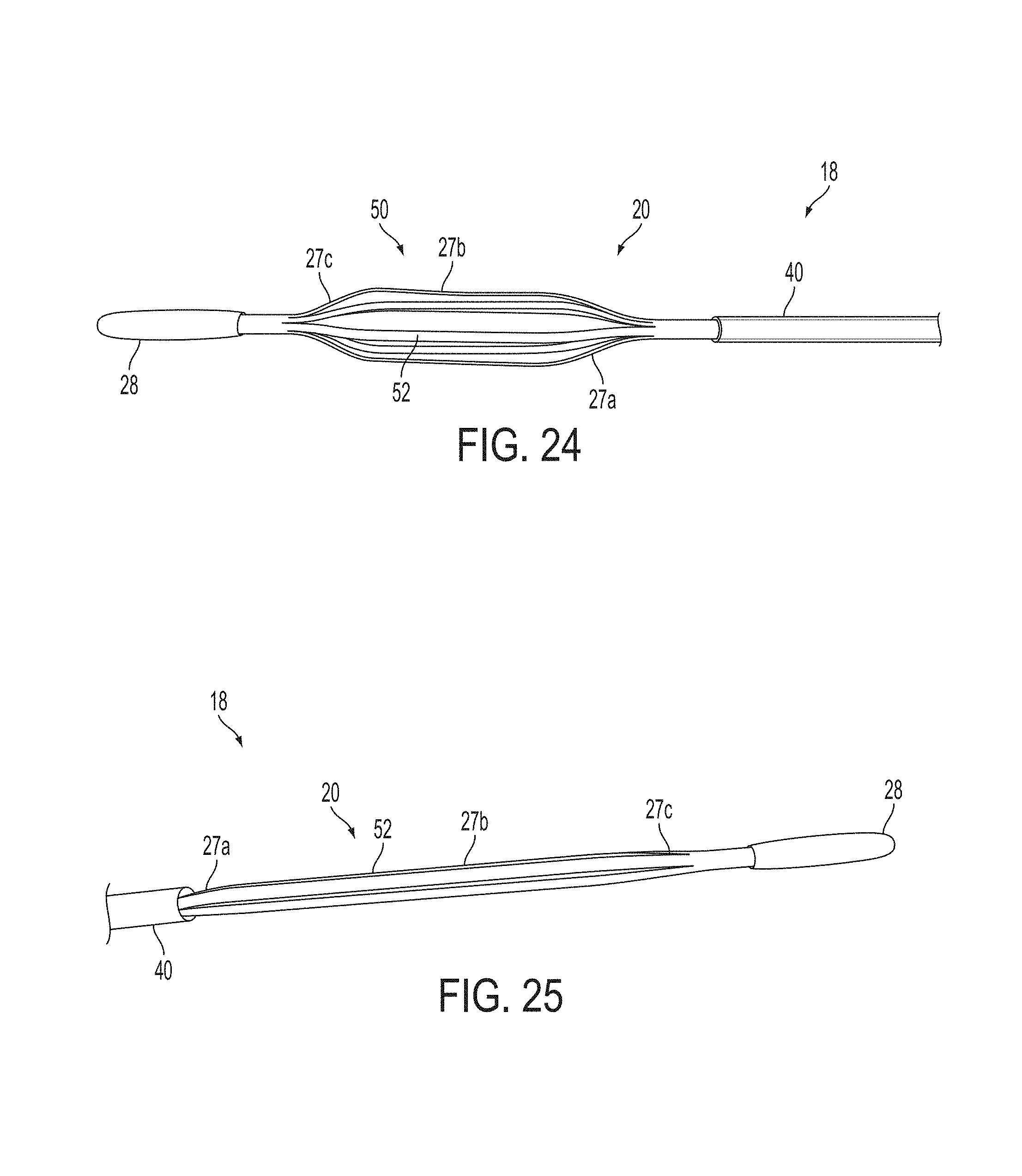
D00014
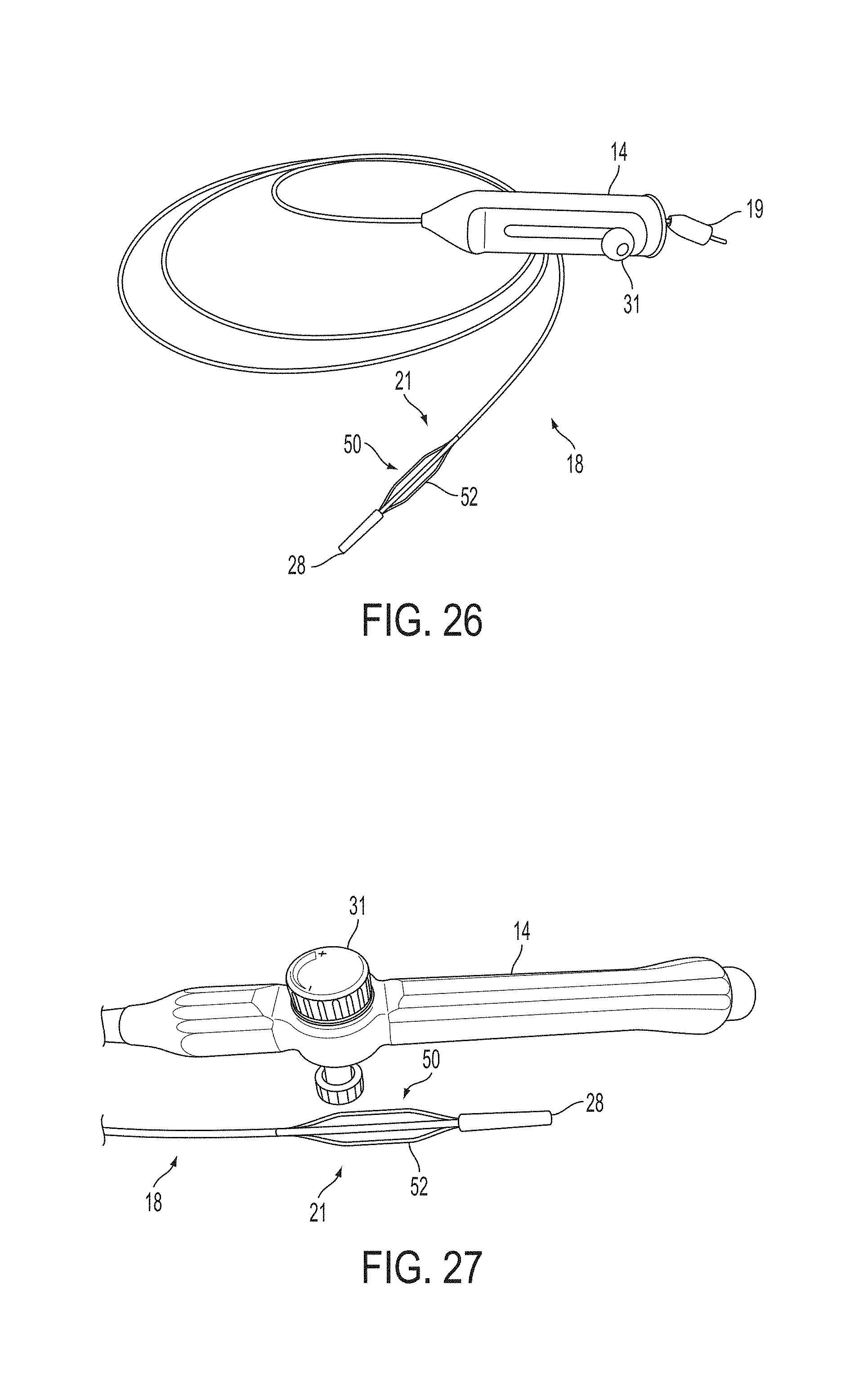
D00015

D00016

XML
uspto.report is an independent third-party trademark research tool that is not affiliated, endorsed, or sponsored by the United States Patent and Trademark Office (USPTO) or any other governmental organization. The information provided by uspto.report is based on publicly available data at the time of writing and is intended for informational purposes only.
While we strive to provide accurate and up-to-date information, we do not guarantee the accuracy, completeness, reliability, or suitability of the information displayed on this site. The use of this site is at your own risk. Any reliance you place on such information is therefore strictly at your own risk.
All official trademark data, including owner information, should be verified by visiting the official USPTO website at www.uspto.gov. This site is not intended to replace professional legal advice and should not be used as a substitute for consulting with a legal professional who is knowledgeable about trademark law.