Cycling shoe power sensors
Smith September 29, 2
U.S. patent number 10,786,706 [Application Number 16/506,085] was granted by the patent office on 2020-09-29 for cycling shoe power sensors. This patent grant is currently assigned to ICON Health & Fitness, Inc.. The grantee listed for this patent is ICON Health & Fitness, Inc.. Invention is credited to Kent M. Smith.
| United States Patent | 10,786,706 |
| Smith | September 29, 2020 |
Cycling shoe power sensors
Abstract
A cycling shoe for measuring power includes a sole having a pocket in the bottom of the sole. A sensor platform having a plurality of sensors, at least one sensor on a top of the sensor platform and at least one sensor on the bottom of the sensor platform, is inserted into the pocket. A platform cover and a cleat are attached to the sole over the sensors. Force applied to a pedal clipped to the cleat is measured and processed.
| Inventors: | Smith; Kent M. (Nibley, UT) | ||||||||||
|---|---|---|---|---|---|---|---|---|---|---|---|
| Applicant: |
|
||||||||||
| Assignee: | ICON Health & Fitness, Inc.
(Logan, UT) |
||||||||||
| Family ID: | 69138987 | ||||||||||
| Appl. No.: | 16/506,085 | ||||||||||
| Filed: | July 9, 2019 |
Prior Publication Data
| Document Identifier | Publication Date | |
|---|---|---|
| US 20200016459 A1 | Jan 16, 2020 | |
Related U.S. Patent Documents
| Application Number | Filing Date | Patent Number | Issue Date | ||
|---|---|---|---|---|---|
| 62697833 | Jul 13, 2018 | ||||
| Current U.S. Class: | 1/1 |
| Current CPC Class: | A43B 3/0005 (20130101); A63B 21/4034 (20151001); A63B 24/0062 (20130101); B62M 3/086 (20130101); A43B 5/14 (20130101); B62J 45/41 (20200201); A63B 2220/51 (20130101); A63B 22/0664 (20130101); A63B 22/0605 (20130101); A63B 2225/20 (20130101); A63B 2220/40 (20130101); A43B 13/026 (20130101); A63B 2225/52 (20130101); A63B 2220/836 (20130101) |
| Current International Class: | A63B 24/00 (20060101); A43B 3/00 (20060101); A43B 5/14 (20060101) |
References Cited [Referenced By]
U.S. Patent Documents
| 3123646 | March 1964 | Easton |
| 3579339 | May 1971 | Chang et al. |
| 4023795 | May 1977 | Pauls |
| 4300760 | November 1981 | Bobroff |
| D286311 | October 1986 | Martinell et al. |
| 4681318 | July 1987 | Lay |
| 4684126 | August 1987 | Dalebout et al. |
| 4728102 | March 1988 | Pauls |
| 4750736 | June 1988 | Watterson |
| 4796881 | January 1989 | Watterson |
| 4813667 | March 1989 | Watterson |
| 4830371 | May 1989 | Lay |
| 4844451 | July 1989 | Bersonnet et al. |
| 4850585 | July 1989 | Dalebout |
| D304849 | November 1989 | Watterson |
| 4880225 | November 1989 | Lucas et al. |
| 4883272 | November 1989 | Lay |
| D306468 | March 1990 | Watterson |
| D306891 | March 1990 | Watterson |
| 4913396 | April 1990 | Dalebout et al. |
| D307614 | May 1990 | Bingham et al. |
| D307615 | May 1990 | Bingham et al. |
| 4921242 | May 1990 | Watterson |
| 4932650 | June 1990 | Bingham et al. |
| D309167 | July 1990 | Griffin |
| D309485 | July 1990 | Bingham et al. |
| 4938478 | July 1990 | Lay |
| D310253 | August 1990 | Bersonnet et al. |
| 4955599 | September 1990 | Bersonnet et al. |
| 4971316 | November 1990 | Dalebout et al. |
| D313055 | December 1990 | Watterson |
| 4974832 | December 1990 | Dalebout |
| 4979737 | December 1990 | Kock |
| 4981294 | January 1991 | Dalebout et al. |
| D315765 | March 1991 | Measom et al. |
| 4998725 | March 1991 | Watterson et al. |
| 5000442 | March 1991 | Dalebout et al. |
| 5000443 | March 1991 | Dalebout et al. |
| 5000444 | March 1991 | Dalebout et al. |
| D316124 | April 1991 | Dalebout et al. |
| 5013033 | May 1991 | Watterson et al. |
| 5014980 | May 1991 | Bersonnet et al. |
| 5016871 | May 1991 | Dalebout et al. |
| D318085 | July 1991 | Jacobson et al. |
| D318086 | July 1991 | Bingham et al. |
| D318699 | July 1991 | Jacobson et al. |
| 5029801 | July 1991 | Dalebout et al. |
| 5034576 | July 1991 | Dalebout et al. |
| 5046382 | September 1991 | Steinberg |
| 5058881 | October 1991 | Measom |
| 5058882 | October 1991 | Dalebout et al. |
| D321388 | November 1991 | Dalebout |
| 5062626 | November 1991 | Dalebout et al. |
| 5062627 | November 1991 | Bingham |
| 5062632 | November 1991 | Dalebout et al. |
| 5062633 | November 1991 | Engel et al. |
| 5067710 | November 1991 | Watterson et al. |
| 5072929 | December 1991 | Peterson et al. |
| D323009 | January 1992 | Dalebout et al. |
| D323198 | January 1992 | Dalebout et al. |
| D323199 | January 1992 | Dalebout et al. |
| D323863 | February 1992 | Watterson |
| 5088729 | February 1992 | Dalebout |
| 5090694 | February 1992 | Pauls et al. |
| 5102380 | April 1992 | Jacobson et al. |
| 5104120 | April 1992 | Watterson et al. |
| 5108093 | April 1992 | Watterson |
| D326491 | May 1992 | Dalebout |
| 5122105 | June 1992 | Engel et al. |
| 5135216 | August 1992 | Bingham et al. |
| 5147265 | September 1992 | Pauls et al. |
| 5149084 | September 1992 | Dalebout et al. |
| 5149312 | September 1992 | Croft et al. |
| 5171196 | December 1992 | Lynch |
| D332347 | January 1993 | Raadt et al. |
| 5190505 | March 1993 | Dalebout et al. |
| 5192255 | March 1993 | Dalebout et al. |
| 5195937 | March 1993 | Engel et al. |
| 5203826 | April 1993 | Dalebout |
| D335511 | May 1993 | Engel et al. |
| D335905 | May 1993 | Cutter et al. |
| D336498 | June 1993 | Engel et al. |
| 5217487 | June 1993 | Engel et al. |
| D337361 | July 1993 | Engel et al. |
| D337666 | July 1993 | Peterson et al. |
| D337799 | July 1993 | Cutter et al. |
| 5226866 | July 1993 | Engel et al. |
| 5244446 | September 1993 | Engel et al. |
| 5247853 | September 1993 | Dalebout |
| 5259611 | November 1993 | Dalebout et al. |
| D342106 | December 1993 | Campbell et al. |
| 5279528 | January 1994 | Dalebout et al. |
| D344112 | February 1994 | Smith |
| D344557 | February 1994 | Ashby |
| 5282776 | February 1994 | Dalebout |
| 5295931 | March 1994 | Dreibelbis et al. |
| 5302161 | April 1994 | Loubert et al. |
| D347251 | May 1994 | Dreibelbis et al. |
| 5316534 | May 1994 | Dalebout et al. |
| D348493 | July 1994 | Ashby |
| D348494 | July 1994 | Ashby |
| 5328164 | July 1994 | Soga |
| D349931 | August 1994 | Bostic et al. |
| 5336142 | August 1994 | Dalebout et al. |
| 5344376 | September 1994 | Bostic et al. |
| D351202 | October 1994 | Bingham |
| D351435 | October 1994 | Peterson et al. |
| D351633 | October 1994 | Bingham |
| D352534 | November 1994 | Dreibelbis et al. |
| D353422 | December 1994 | Bostic et al. |
| 5372559 | December 1994 | Dalebout et al. |
| 5374228 | December 1994 | Buisman et al. |
| 5382221 | January 1995 | Hsu et al. |
| 5387168 | February 1995 | Bostic |
| 5393690 | February 1995 | Fu et al. |
| D356128 | March 1995 | Smith et al. |
| 5409435 | April 1995 | Daniels |
| 5429563 | July 1995 | Engel et al. |
| 5431612 | July 1995 | Holden |
| D360915 | August 1995 | Bostic et al. |
| 5468205 | November 1995 | McFall et al. |
| 5489249 | February 1996 | Brewer et al. |
| 5492517 | February 1996 | Bostic et al. |
| D367689 | March 1996 | Wilkinson et al. |
| 5511740 | April 1996 | Loubert et al. |
| 5512025 | April 1996 | Dalebout et al. |
| D370949 | June 1996 | Furner |
| D371176 | June 1996 | Furner |
| 5527245 | June 1996 | Dalebout |
| 5529553 | June 1996 | Finlayson |
| 5540429 | July 1996 | Dalebout et al. |
| 5549533 | August 1996 | Olson et al. |
| 5554085 | September 1996 | Dalebout |
| 5569128 | October 1996 | Dalebout |
| 5591105 | January 1997 | Dalebout et al. |
| 5591106 | January 1997 | Dalebout et al. |
| 5595556 | January 1997 | Dalebout et al. |
| 5607375 | March 1997 | Dalebout |
| 5611539 | March 1997 | Watterson |
| 5622527 | April 1997 | Watterson et al. |
| 5626538 | May 1997 | Dalebout et al. |
| 5626542 | May 1997 | Dalebout et al. |
| D380024 | June 1997 | Novak et al. |
| 5637059 | June 1997 | Dalebout |
| D380509 | July 1997 | Wilkinson et al. |
| 5643153 | July 1997 | Nylen et al. |
| 5645509 | July 1997 | Brewer et al. |
| D384118 | September 1997 | Deblauw |
| 5662557 | September 1997 | Watterson et al. |
| 5669857 | September 1997 | Watterson et al. |
| 5672140 | September 1997 | Watterson et al. |
| 5674156 | October 1997 | Watterson et al. |
| 5674453 | October 1997 | Watterson et al. |
| 5676624 | October 1997 | Watterson et al. |
| 5683331 | November 1997 | Dalebout |
| 5683332 | November 1997 | Watterson et al. |
| D387825 | December 1997 | Fleck et al. |
| 5695433 | December 1997 | Buisman |
| 5695434 | December 1997 | Dalebout et al. |
| 5695435 | December 1997 | Dalebout et al. |
| 5702325 | December 1997 | Watterson et al. |
| 5704879 | January 1998 | Watterson et al. |
| 5718657 | February 1998 | Dalebout et al. |
| 5720200 | February 1998 | Anderson et al. |
| 5720698 | February 1998 | Dalebout et al. |
| D392006 | March 1998 | Dalebout et al. |
| 5722922 | March 1998 | Watterson et al. |
| 5733229 | March 1998 | Dalebout et al. |
| 5743833 | April 1998 | Watterson et al. |
| 5762584 | June 1998 | Daniels |
| 5762587 | June 1998 | Dalebout et al. |
| 5772560 | June 1998 | Watterson et al. |
| 5810698 | September 1998 | Hullett et al. |
| 5813142 | September 1998 | Demon |
| 5827155 | October 1998 | Jensen |
| 5830114 | November 1998 | Halfen et al. |
| 5860893 | January 1999 | Watterson et al. |
| 5860894 | January 1999 | Dalebout et al. |
| 5899834 | May 1999 | Dalebout et al. |
| D412953 | August 1999 | Armstrong |
| D413948 | September 1999 | Dalebout |
| 5951441 | September 1999 | Dalebout |
| 5951448 | September 1999 | Bolland |
| D416596 | November 1999 | Armstrong |
| 6003166 | December 1999 | Hald et al. |
| 6019710 | February 2000 | Dalebout et al. |
| 6027429 | February 2000 | Daniels |
| 6033347 | March 2000 | Dalebout et al. |
| D425940 | May 2000 | Halfen et al. |
| 6059692 | May 2000 | Hickman |
| D428949 | August 2000 | Simonson |
| 6123646 | September 2000 | Colassi |
| 6171217 | January 2001 | Cutler |
| 6171219 | January 2001 | Simonson |
| 6174267 | January 2001 | Dalebout |
| 6193631 | February 2001 | Hickman |
| 6228003 | May 2001 | Hald et al. |
| 6238323 | May 2001 | Simonson |
| 6251052 | June 2001 | Simonson |
| 6261022 | July 2001 | Dalebout et al. |
| 6280362 | August 2001 | Dalebout et al. |
| 6296594 | October 2001 | Simonson |
| D450872 | November 2001 | Dalebout et al. |
| 6312363 | November 2001 | Watterson et al. |
| D452338 | December 2001 | Dalebout et al. |
| D453543 | February 2002 | Cutler |
| D453948 | February 2002 | Cutler |
| 6350218 | February 2002 | Dalebout et al. |
| 6387020 | May 2002 | Simonson |
| 6413191 | July 2002 | Harris et al. |
| 6422980 | July 2002 | Simonson |
| 6447424 | September 2002 | Ashby et al. |
| 6458060 | October 2002 | Watterson et al. |
| 6458061 | October 2002 | Simonson |
| 6471622 | October 2002 | Hammer et al. |
| 6563225 | May 2003 | Soga et al. |
| 6601016 | July 2003 | Brown et al. |
| 6623140 | September 2003 | Watterson |
| 6626799 | September 2003 | Watterson et al. |
| 6652424 | November 2003 | Dalebout |
| 6685607 | February 2004 | Olson |
| 6695581 | February 2004 | Wasson et al. |
| 6701271 | March 2004 | Willner et al. |
| 6702719 | March 2004 | Brown et al. |
| 6712740 | March 2004 | Simonson |
| 6730002 | May 2004 | Hald et al. |
| 6743153 | June 2004 | Watterson et al. |
| 6746371 | June 2004 | Brown et al. |
| 6749537 | June 2004 | Hickman |
| 6761667 | July 2004 | Cutler et al. |
| 6770015 | August 2004 | Simonson |
| 6786852 | September 2004 | Watterson et al. |
| 6808472 | October 2004 | Hickman |
| 6821230 | November 2004 | Dalebout et al. |
| 6830540 | December 2004 | Watterson |
| 6863641 | March 2005 | Brown et al. |
| 6866613 | March 2005 | Brown et al. |
| 6875160 | April 2005 | Watterson et al. |
| D507311 | July 2005 | Butler et al. |
| 6918858 | July 2005 | Watterson et al. |
| 6921351 | July 2005 | Hickman et al. |
| 6974404 | December 2005 | Watterson et al. |
| 6997852 | February 2006 | Watterson et al. |
| 7025713 | April 2006 | Dalebout |
| D520085 | May 2006 | Willardson et al. |
| 7044897 | May 2006 | Myers et al. |
| 7052442 | May 2006 | Watterson |
| 7060006 | June 2006 | Watterson et al. |
| 7060008 | June 2006 | Watterson et al. |
| 7070539 | July 2006 | Brown et al. |
| 7097588 | August 2006 | Watterson |
| D527776 | September 2006 | Willardson et al. |
| 7112168 | September 2006 | Dalebout et al. |
| 7128693 | October 2006 | Brown et al. |
| 7166062 | January 2007 | Watterson et al. |
| 7166064 | January 2007 | Watterson et al. |
| 7169087 | January 2007 | Ercanbrack et al. |
| 7169093 | January 2007 | Simonson et al. |
| 7192388 | March 2007 | Dalebout et al. |
| 7250022 | July 2007 | Dalebout |
| 7282016 | October 2007 | Simonson |
| 7285075 | October 2007 | Cutler et al. |
| 7344481 | March 2008 | Watterson et al. |
| 7377882 | May 2008 | Watterson |
| 7425188 | September 2008 | Ercanbrack |
| 7429236 | September 2008 | Dalebout et al. |
| 7455622 | November 2008 | Watterson et al. |
| 7482050 | January 2009 | Olson |
| D588655 | March 2009 | Utykanski |
| 7510509 | March 2009 | Hickman |
| 7537546 | May 2009 | Watterson et al. |
| 7537549 | May 2009 | Nelson et al. |
| 7537552 | May 2009 | Dalebout et al. |
| 7540828 | June 2009 | Watterson et al. |
| 7549947 | June 2009 | Hickman et al. |
| 7556590 | July 2009 | Watterson et al. |
| 7563203 | July 2009 | Dalebout et al. |
| 7575536 | August 2009 | Hickman |
| 7601105 | October 2009 | Gipson, III et al. |
| 7604573 | October 2009 | Dalebout et al. |
| D604373 | November 2009 | Dalebout et al. |
| 7618350 | November 2009 | Dalebout et al. |
| 7618357 | November 2009 | Dalebout |
| 7625315 | December 2009 | Hickman |
| 7625321 | December 2009 | Simonson et al. |
| 7628730 | December 2009 | Watterson et al. |
| 7628737 | December 2009 | Kowallis et al. |
| 7637847 | December 2009 | Hickman |
| 7645212 | January 2010 | Ashby et al. |
| 7645213 | January 2010 | Watterson |
| 7658698 | February 2010 | Pacheco et al. |
| 7674205 | March 2010 | Dalebout et al. |
| 7713171 | May 2010 | Hickman |
| 7713172 | May 2010 | Watterson et al. |
| 7713180 | May 2010 | Wickens |
| 7717828 | May 2010 | Simonson et al. |
| 7736279 | June 2010 | Dalebout et al. |
| 7740563 | June 2010 | Dalebout et al. |
| 7749144 | July 2010 | Hammer |
| 7766797 | August 2010 | Dalebout |
| 7771329 | August 2010 | Dalebout et al. |
| 7775940 | August 2010 | Dalebout et al. |
| 7789800 | September 2010 | Watterson et al. |
| 7798946 | September 2010 | Dalebout et al. |
| 7815550 | October 2010 | Watterson et al. |
| 7837595 | November 2010 | Rice |
| 7839058 | November 2010 | Churchill |
| 7857731 | December 2010 | Hickman et al. |
| 7862475 | January 2011 | Watterson |
| 7862478 | January 2011 | Watterson et al. |
| 7862483 | January 2011 | Hendrickson et al. |
| D635207 | March 2011 | Dalebout et al. |
| 7901330 | March 2011 | Dalebout et al. |
| 7909740 | March 2011 | Dalebout et al. |
| 7980996 | July 2011 | Hickman |
| 7981000 | July 2011 | Watterson et al. |
| 7985164 | July 2011 | Ashby |
| 8011242 | September 2011 | O'neill |
| 8029415 | October 2011 | Ashby et al. |
| 8033959 | October 2011 | Oleson |
| 8033960 | October 2011 | Dalebout et al. |
| D650451 | December 2011 | Olson et al. |
| D652877 | January 2012 | Dalebout et al. |
| 8122773 | February 2012 | Wyatt |
| 8152702 | April 2012 | Pacheco |
| D659775 | May 2012 | Olson et al. |
| D659777 | May 2012 | Watterson et al. |
| D660383 | May 2012 | Watterson et al. |
| D664613 | July 2012 | Dalebout et al. |
| 8251874 | August 2012 | Ashby et al. |
| 8298123 | October 2012 | Hickman |
| 8298125 | October 2012 | Colledge et al. |
| D671177 | November 2012 | Sip |
| D671178 | November 2012 | Sip |
| 8327723 | December 2012 | Roudergues |
| D673626 | January 2013 | Olson et al. |
| 8370087 | February 2013 | Zhu |
| 8387470 | March 2013 | Tuulari |
| 8522625 | September 2013 | Philipps |
| 8584520 | November 2013 | Kokkoneva |
| 8683874 | April 2014 | Limacher |
| 8690735 | April 2014 | Watterson et al. |
| D707763 | June 2014 | Cutler |
| 8740753 | June 2014 | Olson et al. |
| 8758201 | June 2014 | Ashby et al. |
| 8762077 | June 2014 | Redmond |
| 8771153 | July 2014 | Dalebout et al. |
| 8784270 | July 2014 | Watterson |
| 8808148 | August 2014 | Watterson |
| 8814762 | August 2014 | Butler |
| D712493 | September 2014 | Ercanbrack et al. |
| 8840075 | September 2014 | Olson |
| 8844371 | September 2014 | Limacher |
| 8845493 | September 2014 | Watterson et al. |
| 8870726 | October 2014 | Watterson et al. |
| 8876668 | November 2014 | Hendrickson et al. |
| 8894549 | November 2014 | Colledge |
| 8894555 | November 2014 | Olson |
| 8911330 | December 2014 | Watterson et al. |
| 8920288 | December 2014 | Dalebout |
| 8986165 | March 2015 | Ashby |
| 8992364 | March 2015 | Law et al. |
| 8992387 | March 2015 | Watterson et al. |
| D726476 | April 2015 | Ercanbrack |
| 9028368 | May 2015 | Ashby et al. |
| 9028370 | May 2015 | Watterson |
| 9039578 | May 2015 | Dalebout |
| D731011 | June 2015 | Buchanan |
| 9063026 | June 2015 | Nassef |
| 9072930 | July 2015 | Ashby et al. |
| 9119983 | September 2015 | Rhea |
| 9123317 | September 2015 | Watterson et al. |
| 9126071 | September 2015 | Smith |
| 9126072 | September 2015 | Watterson |
| 9138615 | September 2015 | Olson et al. |
| 9142139 | September 2015 | Watterson et al. |
| 9144703 | September 2015 | Dalebout et al. |
| 9149683 | September 2015 | Smith |
| 9186535 | November 2015 | Ercanbrack |
| 9186549 | November 2015 | Watterson et al. |
| 9254409 | February 2016 | Dalebout et al. |
| 9254416 | February 2016 | Ashby |
| 9278248 | March 2016 | Tyger |
| 9278249 | March 2016 | Watterson |
| 9278250 | March 2016 | Buchanan |
| 9289648 | March 2016 | Watterson |
| 9331559 | May 2016 | Shastry |
| 9339691 | May 2016 | Brammer |
| 9352185 | May 2016 | Hendrickson et al. |
| 9352186 | May 2016 | Watterson |
| 9375605 | June 2016 | Tyger |
| 9381394 | July 2016 | Mortensen et al. |
| 9387387 | July 2016 | Dalebout |
| 9393453 | July 2016 | Watterson |
| 9403047 | August 2016 | Olson |
| 9403051 | August 2016 | Cutler |
| 9421416 | August 2016 | Mortensen et al. |
| 9457219 | October 2016 | Smith |
| 9457220 | October 2016 | Olson |
| 9457222 | October 2016 | Dalebout |
| 9460632 | October 2016 | Watterson |
| 9463356 | October 2016 | Rhea |
| 9468794 | October 2016 | Barton |
| 9468798 | October 2016 | Dalebout |
| 9476741 | October 2016 | Hollmach |
| 9480874 | November 2016 | Cutler |
| 9492704 | November 2016 | Mortensen et al. |
| 9498668 | November 2016 | Smith |
| 9517378 | December 2016 | Ashby et al. |
| 9521901 | December 2016 | Dalebout |
| 9533187 | January 2017 | Dalebout |
| 9539461 | January 2017 | Ercanbrack |
| 9579544 | February 2017 | Watterson |
| 9586086 | March 2017 | Dalebout et al. |
| 9586090 | March 2017 | Watterson et al. |
| 9604099 | March 2017 | Taylor |
| 9616276 | April 2017 | Dalebout |
| 9616278 | April 2017 | Olson |
| 9623281 | April 2017 | Hendrickson |
| 9636567 | May 2017 | Brammer et al. |
| 9675839 | June 2017 | Dalebout |
| 9682307 | June 2017 | Dalebout |
| 9694234 | July 2017 | Dalebout et al. |
| 9694242 | July 2017 | Ashby |
| 9737755 | August 2017 | Dalebout |
| 9757605 | September 2017 | Olson et al. |
| 9764186 | September 2017 | Dalebout |
| 9767785 | September 2017 | Ashby |
| 9795822 | October 2017 | Smith et al. |
| 9808672 | November 2017 | Dalebout |
| 9849326 | December 2017 | Smith |
| 9878210 | January 2018 | Watterson |
| 9889334 | February 2018 | Ashby et al. |
| 9889339 | February 2018 | Douglass |
| 9937376 | April 2018 | McInelly et al. |
| 9937377 | April 2018 | McInelly et al. |
| 9937378 | April 2018 | Dalebout et al. |
| 9937379 | April 2018 | Mortensen |
| 9943719 | April 2018 | Smith et al. |
| 9943722 | April 2018 | Dalebout |
| 9948037 | April 2018 | Ashby |
| 9968816 | May 2018 | Olson et al. |
| 9968821 | May 2018 | Finlayson et al. |
| 9968823 | May 2018 | Cutler |
| 10010755 | July 2018 | Watterson |
| 10010756 | July 2018 | Watterson |
| 10029145 | July 2018 | Douglass |
| D826350 | August 2018 | Hochstrasser |
| 10046196 | August 2018 | Ercanbrack |
| D827733 | September 2018 | Hochstrasser |
| 10065064 | September 2018 | Smith et al. |
| 10071285 | September 2018 | Smith et al. |
| 10085586 | October 2018 | Smith et al. |
| 10086254 | October 2018 | Watterson |
| 10136842 | November 2018 | Ashby |
| 10186161 | January 2019 | Watterson |
| 10188890 | January 2019 | Olson |
| 16750925 | January 2019 | Silcock |
| 10207143 | February 2019 | Dalebout |
| 10207145 | February 2019 | Tyger |
| 10207147 | February 2019 | Ercanbrack |
| 10207148 | February 2019 | Powell |
| 10212994 | February 2019 | Watterson |
| 10220259 | March 2019 | Brammer |
| 10226396 | March 2019 | Ashby |
| 10226664 | March 2019 | Dalebout |
| 10252109 | April 2019 | Watterson |
| 10258828 | April 2019 | Dalebout |
| 10272317 | April 2019 | Watterson |
| 10279212 | May 2019 | Dalebout et al. |
| 10293211 | May 2019 | Watterson et al. |
| D852292 | June 2019 | Cutler |
| 10343017 | July 2019 | Jackson |
| 10376736 | August 2019 | Powell et al. |
| 10388183 | August 2019 | Watterson |
| 10391361 | August 2019 | Watterson |
| D864320 | October 2019 | Weston |
| D864321 | October 2019 | Weston |
| 10426989 | October 2019 | Dalebout |
| 10433612 | October 2019 | Ashby |
| 10441840 | October 2019 | Dalebout |
| 10449416 | October 2019 | Dalebout |
| 62914007 | October 2019 | Willardson |
| D868909 | December 2019 | Cutler et al. |
| 10492519 | December 2019 | Capell et al. |
| 10493349 | December 2019 | Watterson |
| 10500473 | December 2019 | Watterson |
| 10543395 | January 2020 | Powell et al. |
| 16742762 | January 2020 | Watterson |
| 16780765 | February 2020 | Watterson |
| 16797850 | February 2020 | Watterson |
| 2002/0016235 | February 2002 | Ashby et al. |
| 2002/0077221 | June 2002 | Dalebout et al. |
| 2002/0159253 | October 2002 | Dalebout et al. |
| 2003/0045406 | March 2003 | Stone |
| 2004/0091307 | May 2004 | James |
| 2004/0171464 | September 2004 | Ashby et al. |
| 2004/0171465 | September 2004 | Hald et al. |
| 2005/0049123 | March 2005 | Dalebout et al. |
| 2005/0077805 | April 2005 | Dalebout et al. |
| 2005/0107229 | May 2005 | Wickens |
| 2005/0164839 | July 2005 | Watterson et al. |
| 2005/0272577 | December 2005 | Olson et al. |
| 2006/0248965 | November 2006 | Wyatt |
| 2007/0117683 | May 2007 | Ercanbrack et al. |
| 2007/0130804 | June 2007 | Levy |
| 2007/0254778 | November 2007 | Ashby |
| 2008/0051256 | February 2008 | Ashby et al. |
| 2008/0229875 | September 2008 | Ray |
| 2008/0242520 | October 2008 | Hubbard |
| 2008/0300110 | December 2008 | Smith et al. |
| 2009/0105052 | April 2009 | Dalebout et al. |
| 2010/0242246 | September 2010 | Dalebout et al. |
| 2011/0054359 | March 2011 | Sazonov |
| 2012/0237911 | September 2012 | Watterson |
| 2012/0295774 | November 2012 | Dalebout et al. |
| 2013/0123083 | May 2013 | Sip |
| 2013/0154441 | June 2013 | Redmond |
| 2013/0165195 | June 2013 | Watterson |
| 2013/0172152 | July 2013 | Watterson |
| 2013/0172153 | July 2013 | Watterson |
| 2013/0178334 | July 2013 | Brammer |
| 2013/0178768 | July 2013 | Dalebout |
| 2013/0190136 | July 2013 | Watterson |
| 2013/0196298 | August 2013 | Watterson |
| 2013/0196821 | August 2013 | Watterson et al. |
| 2013/0196822 | August 2013 | Watterson et al. |
| 2013/0218585 | August 2013 | Watterson |
| 2013/0244836 | September 2013 | Maughan |
| 2013/0267383 | October 2013 | Watterson |
| 2013/0268101 | October 2013 | Brammer |
| 2013/0274067 | October 2013 | Watterson et al. |
| 2013/0281241 | October 2013 | Watterson |
| 2014/0024499 | January 2014 | Watterson |
| 2014/0073970 | March 2014 | Ashby |
| 2014/0121071 | May 2014 | Strom et al. |
| 2014/0135173 | May 2014 | Watterson |
| 2014/0274574 | September 2014 | Shorten et al. |
| 2014/0274579 | September 2014 | Olson |
| 2014/0287884 | September 2014 | Buchanan |
| 2014/0309085 | October 2014 | Watterson et al. |
| 2015/0177083 | June 2015 | Redmond |
| 2015/0182779 | July 2015 | Dalebout |
| 2015/0182781 | July 2015 | Watterson |
| 2015/0238817 | August 2015 | Watterson |
| 2015/0250418 | September 2015 | Ashby |
| 2015/0251055 | September 2015 | Ashby |
| 2015/0253210 | September 2015 | Ashby et al. |
| 2015/0253735 | September 2015 | Watterson |
| 2015/0253736 | September 2015 | Watterson |
| 2015/0258560 | September 2015 | Ashby |
| 2015/0352396 | December 2015 | Dalebout |
| 2016/0058335 | March 2016 | Ashby |
| 2016/0063615 | March 2016 | Watterson |
| 2016/0092909 | March 2016 | Watterson |
| 2016/0101311 | April 2016 | Workman |
| 2016/0107065 | April 2016 | Brammer |
| 2016/0121074 | May 2016 | Ashby |
| 2016/0148535 | May 2016 | Ashby |
| 2016/0148536 | May 2016 | Ashby |
| 2016/0158595 | June 2016 | Dalebout |
| 2016/0206922 | July 2016 | Dalebout et al. |
| 2016/0219968 | August 2016 | Martin |
| 2016/0250519 | September 2016 | Watterson |
| 2016/0253918 | September 2016 | Watterson |
| 2016/0346595 | December 2016 | Dalebout et al. |
| 2017/0036053 | February 2017 | Smith et al. |
| 2017/0056711 | March 2017 | Dalebout et al. |
| 2017/0056715 | March 2017 | Dalebout et al. |
| 2017/0056726 | March 2017 | Dalebout et al. |
| 2017/0124912 | May 2017 | Ashby et al. |
| 2017/0193578 | July 2017 | Watterson |
| 2017/0266481 | September 2017 | Dalebout |
| 2017/0266483 | September 2017 | Dalebout et al. |
| 2017/0266489 | September 2017 | Douglass et al. |
| 2017/0266533 | September 2017 | Dalebout |
| 2017/0270820 | September 2017 | Ashby |
| 2018/0001135 | January 2018 | Powell |
| 2018/0036585 | February 2018 | Powell |
| 2018/0085630 | March 2018 | Capell et al. |
| 2018/0089396 | March 2018 | Capell et al. |
| 2018/0099116 | April 2018 | Ashby |
| 2018/0099179 | April 2018 | Chatterton et al. |
| 2018/0099180 | April 2018 | Wilkinson |
| 2018/0111034 | April 2018 | Watterson |
| 2018/0117383 | May 2018 | Workman |
| 2018/0117385 | May 2018 | Watterson et al. |
| 2018/0117393 | May 2018 | Ercanbrack |
| 2018/0154205 | June 2018 | Watterson |
| 2018/0154207 | June 2018 | Hochstrasser |
| 2018/0154209 | June 2018 | Watterson |
| 2018/0200566 | July 2018 | Weston |
| 2019/0058370 | February 2019 | Tinney |
| 2019/0080624 | March 2019 | Watterson |
| 2019/0151698 | May 2019 | Olson |
| 2019/0168072 | June 2019 | Brammer |
| 2019/0178313 | June 2019 | Wrobel |
| 2019/0192898 | June 2019 | Dalebout |
| 2019/0192952 | June 2019 | Powell |
| 2019/0209893 | July 2019 | Watterson |
| 2019/0223612 | July 2019 | Watterson |
| 2019/0232112 | August 2019 | Dalebout |
| 2019/0269958 | September 2019 | Dalebout et al. |
| 2019/0269971 | September 2019 | Capell et al. |
| 2019/0275366 | September 2019 | Powell |
| 2019/0282852 | September 2019 | Dalebout |
| 2019/0328079 | October 2019 | Ashby et al. |
| 2019/0329091 | October 2019 | Powell et al. |
| 2019/0376585 | December 2019 | Buchanan |
| 2020/0009417 | January 2020 | Dalebout |
| 2020/0016459 | January 2020 | Smith |
| 101458386 | Nov 2014 | KR | |||
| M424795 | Mar 2012 | TW | |||
| M447216 | Feb 2013 | TW | |||
| 2009082215 | Jul 2009 | WO | |||
Other References
|
US. Appl. No. 13/088,007, filed Apr. 15, 2011, Scott R. Watterson. cited by applicant . U.S. Appl. No. 15/973,176, filed May 7, 2018, Melanie Douglass. cited by applicant . U.S. Appl. No. 29/702,127, filed Sep. 16, 2019, ICON Health & Fitness, Inc. cited by applicant . U.S. Appl. No. 62/796,952, filed Jan. 25, 2019, ICON Health & Fitness, Inc. cited by applicant . U.S. Appl. No. 62/804,146, filed Feb. 11, 2019, ICON Health & Fitness, Inc. cited by applicant . U.S. Appl. No. 62/804,685, filed Feb. 12, 2019, ICON Health & Fitness, Inc. cited by applicant . U.S. Appl. No. 62/852,118, filed May 22, 2019, David Hays. cited by applicant . U.S. Appl. No. 62/866,576, filed Jun. 25, 2019, ICON Health & Fitness, Inc. cited by applicant . U.S. Appl. No. 62/887,391, filed Aug. 15, 2019, ICON Health & Fitness, Inc. cited by applicant . U.S. Appl. No. 62/887,398, filed Aug. 15, 2019, ICON Health & Fitness, Inc. cited by applicant . U.S. Appl. No. 62/897,113, filed Sep. 9, 2019, ICON Health & Fitness, Inc. cited by applicant . International Search Report issued for PCT/US2015/019492 dated May 22, 2015. cited by applicant . Taiwan Search Report and Office Action issued in application No. 104107623 dated Mar. 16, 2016. cited by applicant . International Search Report and Written Opinion issued for PCT/US2019/041014 dated Oct. 25, 2019. cited by applicant. |
Primary Examiner: Dowtin; Jewel V
Attorney, Agent or Firm: Ray Quinney & Nebeker
Parent Case Text
CROSS-REFERENCE TO RELATED APPLICATIONS
This application claims priority to provisional patent application No. 62/697,833 entitled "Cycling Shoe Power Sensors" filed Jul. 13, 2018, which application is herein incorporated by reference for all that it discloses.
Claims
What is claimed is:
1. A device for measuring exercise power comprising: a shoe having a sole, wherein the sole includes a pocket on an outside surface of the sole; and a sensor platform having a top and a bottom, the sensor platform including a plurality of sensors, a first sensor of the plurality of sensors being on the top of the sensor platform, and a second sensor of the plurality of sensors being on the bottom of the sensor platform, wherein the sensor platform is configured to be placed within the pocket.
2. The device of claim 1, wherein the first sensor and the second sensor are force sensors.
3. The device of claim 1, wherein the sensor platform includes a plurality of cleat supports, the first sensor and the second sensor being located on at least one cleat support of the plurality of cleat supports.
4. The device of claim 3, wherein the plurality of cleat supports includes a first cleat support, a second cleat support, and a third cleat support, the second cleat support and third cleat support being rearward of the first cleat support relative to the sole, wherein a third sensor of the plurality of sensors is configured to measure transverse shear force and located on the second cleat support, and a fourth sensor of the plurality of sensors is configured to measure transverse shear force and located on the third cleat support.
5. The device of claim 1, wherein the plurality of sensors includes a plurality of sensor pairs, each sensor pair including a top sensor located on the top of the sensor platform and a bottom sensor located on the bottom of the sensor platform, the top sensor and the bottom sensor being opposite each other on the sensor platform.
6. The device of claim 5, wherein the top sensor and the bottom sensor are strain gauges having an orientation that is the same for both the top sensor and the bottom sensor.
7. The device of claim 1, further comprising a battery located in the sole of the shoe.
8. The device of claim 1, further comprising a processor located in the sole of the shoe, the processor connected to the plurality of sensors by a conduit.
9. A system for measuring cycling power comprising: a cycling shoe having a sole; a sensor platform fastened to an outside of the sole using a plurality of platform fasteners, wherein a plurality of sensors is attached to the sensor platform; and a cleat attached to the sole with a plurality of cleat fasteners and configured to secure the sensor platform to the cycling shoe and releasably connect to a bicycle pedal.
10. The system of claim 9, wherein the cleat is connected to the sole using three cleat fasteners.
11. The system of claim 10, wherein the sensor platform includes three cleat supports, wherein each cleat support includes at least one sensor of the plurality of sensors.
12. The system of claim 9, further comprising a communication device in electronic communication with the plurality of sensors.
13. A method for measuring cycling power comprising: inserting a sensor platform having a plurality of sensors into a pocket located on an outer surface of a sole of a cycling shoe; securing a cleat to the sole using a plurality of cleat fasteners; clipping the cleat to a pedal attached to a crank; rotating the crank by applying a force through the cycling shoe to the pedal; and measuring a magnitude of a plurality of components of the force using the plurality of sensors on the sensor platform.
14. The method of claim 13, further comprising securing the sensor platform to the cycling shoe using a plurality of platform fasteners.
15. The method of claim 13, wherein measuring the magnitude of a plurality of components of the force includes measuring the magnitude of the force periodically according to a measuring rate.
16. The method of claim 15, wherein the measuring rate is greater than 10 measurements per second.
17. The method of claim 13, wherein measuring the magnitude of a plurality of components of the force includes measuring the magnitude with at least one of the plurality of sensors located on a top of the sensor platform and at least one of the plurality of sensors located on a bottom of the sensor package.
18. The method of claim 13, wherein measuring the magnitude of a plurality of components of the force includes measuring, relative to the crank, a radial force in line with the crank, a longitudinal shear stress, and a transverse shear stress.
19. The method of claim 13, further comprising processing the magnitude of a plurality of components of the force.
20. The method of claim 13, further comprising communicating the magnitude of a plurality of components of the force to a remote device.
Description
BACKGROUND
Background and Relevant Art
Cycling is a popular recreational and professional sport. As cyclists progress in the sport, many desire to improve their performance. One way to measure performance is to time how long a cyclist takes to ride a given course. However, it is difficult for cyclists to compare performance for different rides on different courses. Part of this difficulty arises from the many variables that can significantly affect an individual cyclist's performance, such as weather conditions and road conditions. Part of this difficulty also arises from the variables among different courses, including altitude, elevation change, and bicycle construction.
One metric that cyclists use to measure performance that is independent of the time it takes to ride a given course is cycling power. Cycling power is a measure of the power applied by the cyclist to a bicycle. Cycling power measures the force applied to the pedals and crank of a bicycle over a portion of the pedal's rotation for a time interval. Cycling power is a metric that is somewhat independent of road conditions, weather conditions, and elevation change, and therefore is a preferred training and comparison statistic by amateur and professional cyclists alike. Because cycling power is a measure of the force applied to the pedal and crank, power is conventionally measured at the pedal or at the crank.
Biometrics can be tracked through various wearable devices, such as incorporated into a shoe or other articles of clothing. One example of a shoe configured to collect biometric information is described in U.S. patent application Ser. No. 15/821,386 to Ashby, filed Nov. 22, 2017. A shoe has an insole with an opening to a cavity. A sensor is inserted into the cavity. The sensor includes an accelerometer and/or gyroscope to collect movement information of the user's shoes during use.
Another example of an unobtrusive tracking device is disclosed in U.S. Pat. No. 9,224,291 to Moll-Carrillo et al., issued Dec. 29, 2013. Moll-Carrillo discloses recording and displaying athletic data using a computing device such as a mobile communication device during physical activity. The mobile communication device provides options for defining and recording athletic activity performed by the user. The options include content item selection and rendering controls. Moll-Carrillo also discloses route selection and controls.
Yet another example of an unobtrusive tracking device is disclosed in U.S. Pat. No. 8,749,380 to Vock et al., issued Jun. 10, 2014. Vock is directed to tracking the usage of a shoe with a shoe wear-out sensor. Vock further discloses a body bar sensing system for sensing movement of a body bar can be provided. The body bar sensing system includes a housing coupled to the body bar, a detector disposed within the housing to sense movement of the body bar, and a processor to determine a number of repetitions of the movement based on the sensed movement. The body bar sensing system also includes a display to communicate the determined number of repetitions of the movement to a user.
BRIEF SUMMARY
In some embodiments, a device for measuring exercise power may include a shoe having a pocket in an outside surface of the sole of the shoe. A sensor platform having at least one sensor on a top of the sensor platform and at least one sensor on a bottom of the sensor platform may be configured to be placed in the pocket.
In other embodiments, a system for measuring cycling power may include a cycling shoe. A sensor platform having a plurality of sensors may be fastened to an outside of the sole using a plurality of platform fasteners. A cleat may be attached to the sole using a plurality of cleat fasteners and be configured to releasably connect to a bicycle pedal.
In still other embodiments, a method for measuring cycling power may include inserting a sensor platform having a plurality of sensor into a pocket located on an outer surface of a cycling shoe. A cleat may be secured to the sole using a plurality of cleat fasteners and clipped to a pedal attached to a crank. The crank may be rotated by applying a force through the cycling shoe to the pedal. A magnitude of the force may be measured by the plurality of sensors on the sensor platform and the magnitude of the force may be processed using a processor.
Additional features and advantages will be set forth in the description which follows, and in part will be obvious from the description, or may be learned by the practice of the teachings herein. Features and advantages of the invention may be realized and obtained by means of the instruments and combinations particularly pointed out in the appended claims. Features of the present invention will become more fully apparent from the following description and appended claims or may be learned by the practice of the invention as set forth hereinafter.
BRIEF DESCRIPTION OF THE DRAWINGS
In order to describe the manner in which the above-recited and other features of the disclosure can be obtained, a more particular description will be rendered by reference to specific embodiments thereof which are illustrated in the appended drawings. For better understanding, the like elements have been designated by like reference numbers throughout the various accompanying figures. While some of the drawings may be schematic or exaggerated representations of concepts, at least some of the drawings may be drawn to scale. Understanding that the drawings depict some example embodiments, the embodiments will be described and explained with additional specificity and detail through the use of the accompanying drawings in which:
FIG. 1-1 is a perspective view of the sole of a cycling shoe having a sensor platform, according to at least one embodiment of the present disclosure;
FIG. 1-2 is a perspective view of the cycling shoe of FIG. 1-1 having a platform cover over the sensor platform, according to at least one embodiment of the present disclosure;
FIG. 1-3 is another perspective view of the cycling shoe of FIGS. 1-1 and 1-2 having a cleat attached to the platform cover, according to at least one embodiment of the present disclosure;
FIG. 2-1 is a top view of a sensor platform, according to at least one embodiment of the present disclosure;
FIG. 2-2 is a bottom view of the sensor platform of FIG. 2-1, according to at least one embodiment of the present disclosure;
FIG. 3 is a top view of a sole of a cycling shoe, according to at least one embodiment of the present disclosure;
FIG. 4 is a schematic view of a path of a bicycle pedal, according to at least one embodiment of the present disclosure;
FIG. 5 is a representation of a cycling power chart, according to at least one embodiment of the present disclosure; and
FIG. 6 is a representation of a method for measuring cycling power, according to at least one embodiment of the present disclosure.
DETAILED DESCRIPTION
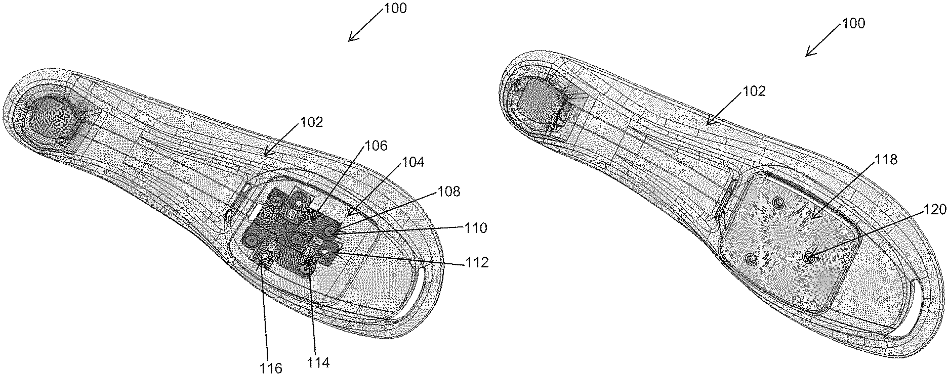
FIG. 1-1 is a perspective view of a cycling shoe 100, according to at least one embodiment of the present disclosure. In some embodiments, the cycling shoe 100 includes a sole 102 with a pocket 104. In some embodiments, the pocket 104 is located on a bottom of the sole 102. In other embodiments, the pocket 104 is located on a top of the sole 102, or, in other words, on the inside of the cycling shoe 100. In some embodiments, the pocket 104 is located on the ball of the cycling shoe 100, or in other words, the front half of the shoe, or where the ball of a foot of a user would be located while wearing the cycling shoe 100.
In some embodiments, the sole 102 is fabricated from carbon fiber. In other embodiments, the sole 102 is fabricated from fiberglass, nylon, PVC, or any other stiff material. The pocket 104 may be molded into the sole 102. For example, a carbon fiber sole 102 may have a mold against which the plies of carbon fiber may be laid, followed by injection or coating of the plies with a matrix, such as epoxy or a thermoplastic. In some embodiments, the sole 102 is fabricated using additive manufacturing, the pocket 104 included in the sole 102 at the time of manufacturing. In other embodiments, the sole 102 is fabricated from a piece of material into which the pocket 104 is machined or milled. For example, the sole 102 may include a thermoplastic polyurethane (TPU), other solid polymer, metal, or metal alloy; and a portion of the sole 102 may be removed to create the pocket 104.
The pocket 104 may include a sensor platform 106. In some embodiments, the pocket 104 is formed to fit the dimensions of the sensor platform 106. In other embodiments, the pocket 104 is formed to accommodate multiple sizes and/or shapes of sensor platforms 106.
In some embodiments, the pocket 104 is open, meaning that the sensor platform 106 may be placed directly in the pocket 104. In other embodiments, the pocket 104 is enclosed, meaning that the sensor platform 106 may be inserted into a small slot or opening into the pocket 104 such that the sensor platform 106 may be substantially enclosed by the pocket 104 when inserted. For example, a substantially enclosed pocket 104 may have a volume of the enclosed pocket 104 at least 80% surrounded by the sole 102.
The sensor platform 106 may include a plurality of platform fastener inserts 108. The platform fastener inserts 108 may be oriented in a pattern around the sensor platform 106. In some embodiments, the sensor platform 106 includes five platform fastener inserts 108. In other embodiments, the sensor platform 106 includes any other number of platform fastener inserts 108, including three, four, six, seven, or eight platform fastener inserts 108. In some embodiments, the sole 102 includes a plurality of sole connections having a matching pattern to the platform fastener inserts 108. In other words, the sole 102 may include the same number of sole connections in the same layout as the sensor platform 106.
Still referring to FIG. 1-1, a plurality of platform fasteners 110 inserted into the plurality of platform fastener inserts 108 and the plurality of sole connections may secure the sensor platform 106 to the sole 102. In some embodiments, the plurality of platform fasteners 110 have a threaded connection. In other embodiments, the plurality of platform fasteners 110 have a press-fit connection. In still other embodiments, the plurality of platform fasteners 110 have a nut and bolt connection to compress the sensor platform 106 to the sole 102. In yet other embodiments, the plurality of platform fasteners 110 have any type of connection designed to secure the sensor platform 106 to the sole 102.
The sensor platform 106 may include a plurality of cleat supports 112 including a plurality of sensors 114. In some embodiments, the sensor platform 106 includes three cleat supports 112. For example, the sensor platform 106 may include cleat supports 112 configured to attach to a standard three-bolt cleat system road biking cleat, such as the SHIMANO SPD-SL. In other embodiments, the sensor platform 106 includes two cleat supports 112. For example, the sensor platform 106 may include cleat supports 112 configured to attach to a standard two-bolt cleat system biking cleat, such as the SHIMANO SPD. In still other embodiments, the sensor platform 106 includes four cleat supports 112 configured to attach to a standard four-bolt cleat system biking cleat, such as used by SPEEDPLAY cleats and pedals.
In some embodiments, a cleat support 112 includes a cleat connection 116. The cleat connection 116 may be configured to connect to a standard cleat bolt, such as those used to attach cleats to cycling shoes.
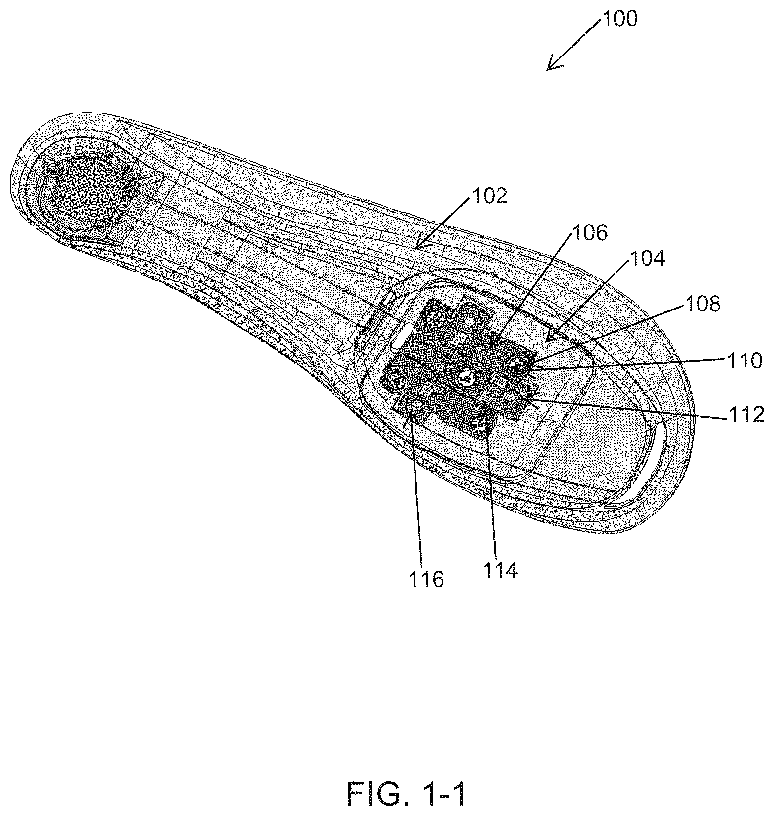
FIG. 1-2 is a representation of the cycling shoe 100 of FIG. 1-2 including a sensor platform cover 118. In some embodiments, the sensor platform cover 118 is configured to match the peripheral outline and/or contour of the pocket in the sole 102 (e.g., pocket 104 of FIG. 1-1). In other embodiments, the sensor platform cover 118 is larger than the outline or contour of the pocket in the sole 102. In yet other embodiments, the sensor platform cover 118 is smaller than the outline or contour of the pocket in the sole 102.
In some embodiments, the sensor platform cover 118 connects to the sole 102 using a snap-fit with the pocket. In other embodiments, the sensor platform cover 118 connects to the sole 102 using a plurality of cover cleat connectors 120. The cover cleat connectors 120 may have the same pattern as the cleat supports (e.g., cleat supports 112 of FIG. 1-1). Thus, sensor platform cover 118 may include two, three, or four cover cleat connectors 120 arranged in a pattern to connect to a standard cleat. In this manner, connecting a cleat (not shown) to the sole 102 through the cover cleat connectors 120 and the sensor platform cleat connection (e.g., cleat connection 116 of FIG. 1-1), may secure the sensor platform cover 118 to the sensor platform (e.g., sensor platform 106 of FIG. 1-1) and the sole 102.
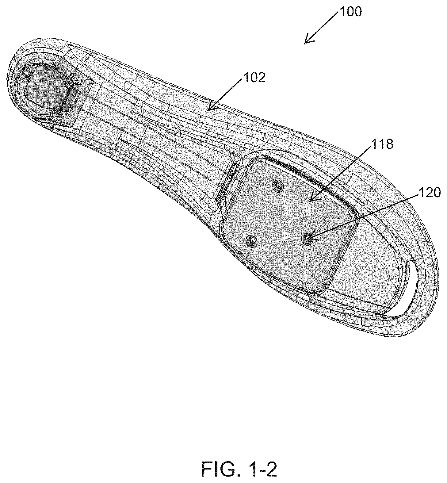
FIG. 1-3 is another perspective view of the cycling shoe 100 of FIGS. 1-1 and 1-2 showing a cleat 122 connected to the sole 102. The cleat 122 may be connected to the sole 102 through the outside of the sensor platform cover 118 and the sensor platform (e.g., sensor platform 106 of FIG. 1-1). The cleat 122 may be connected to the sole 102 using a plurality of cleat fasteners. As described above, in some embodiments, the cleat 122 may be connected to the sole 102 using two, three, or four cleat fasteners, depending on the type of cleat attached.
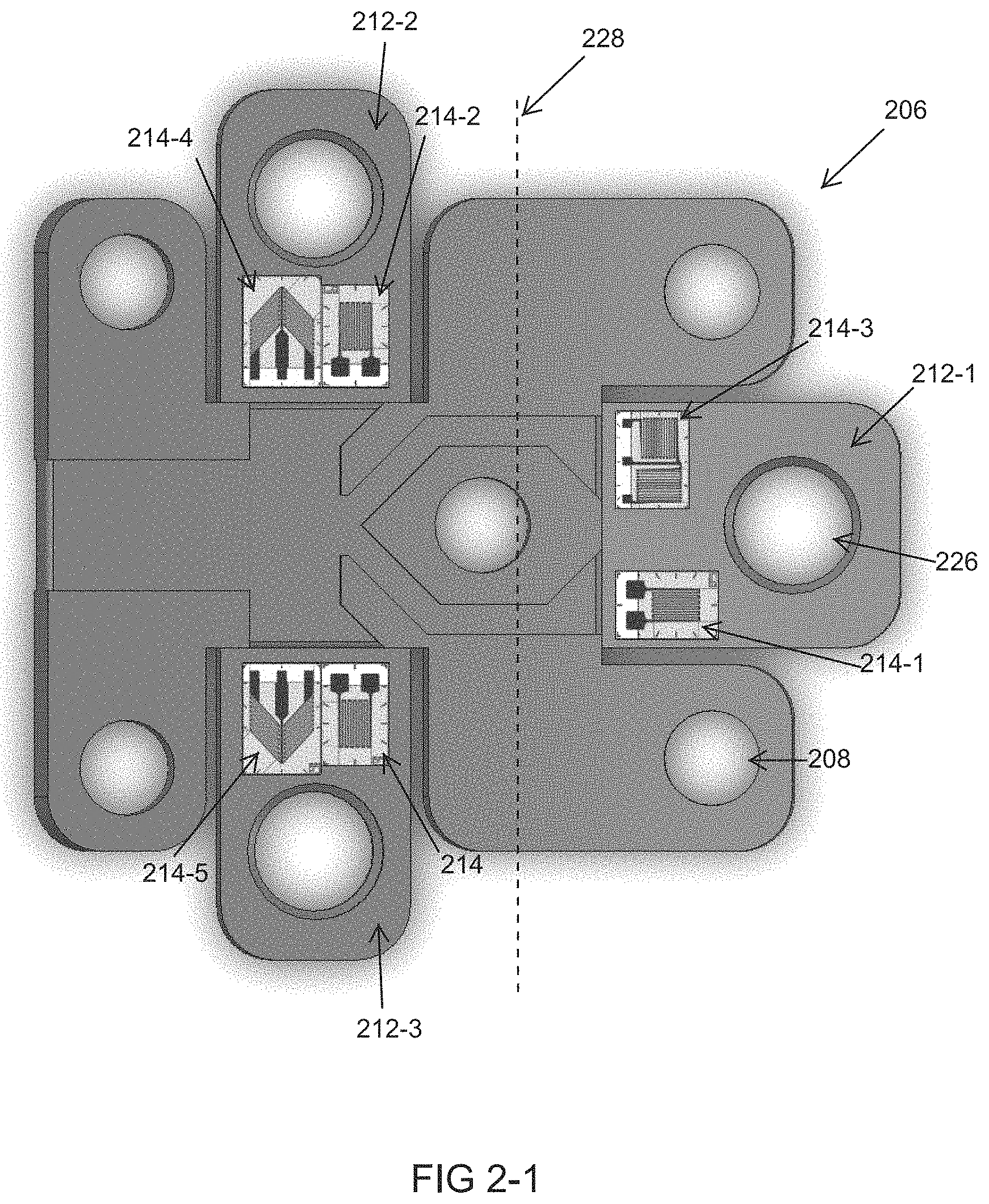
FIG. 2-1 is a top view of a sensor platform 206, according to at least one embodiment of the present disclosure. The sensor platform 206 may include a plurality of platform fastener inserts 208. In some embodiments, the platform fastener inserts 208 are separate components from the sensor platform 206. In other words, the platform fastener inserts 208 may be removable and/or replaceable. At least a portion of the platform fastener inserts 208 may have a non-circular shape, such that when a torque is applied to a fastener (e.g., platform fastener 110 of FIG. 1-1), the platform fastener insert 208 may resist rotation relative to the sensor platform 206. In some embodiments, the platform fastener inserts 208 may be complementary to a fastener. For example, the platform fastener inserts 208 may have threads complementary to the fastener.
In some embodiments, the sensor platform 206 includes a plurality of cleat supports 212-1, 212-2, 212-3. Each cleat support 212-1, 212-2, 212-3 may include a cleat connection 226. The number and arrangement of cleat supports 212-1, 212-2, 212-3 and/or cleat connections 226 may conform to the number and arrangement of cleat fasteners on the cleat to be used (e.g., cleat 122 of FIG. 1-3). For example, there may be two, three, or four cleat supports 212-1, 212-2, 212-3 and/or cleat connections 226. In some embodiments, the cleat supports 212-1, 212-2, 212-3 are reinforced relative to a body of the sensor platform 206, or in other words, have a greater tensile and/or compressive strength. In other embodiments, the cleat supports 212-1, 212-2, 212-3 have approximately the same strength as the body of the sensor platform 206.
The sensor platform 206 may include a plurality of sensors 214. In some embodiments, the plurality of sensors 214 may include a force sensor, a torque sensor, a temperature sensor, an accelerometer, or any combination of the foregoing. In some embodiments, a force sensor includes a strain gauge. In some embodiments, a strain gauge sensor 214 is a temperature-controlled strain gauge sensor 214. For example, the strain gauge sensor 214 may be calibrated to, designed for, and/or applied to the sensor platform 206 specifically to limit any noise or erroneous measurements by the strain gauge sensor 214 caused by the thermal expansion and contraction of the sensor platform 206. In other embodiments, the sensor 214 is an accelerometer. For example, the accelerometer may allow the calculation of cadence or position of the sensor platform 206 in a stroke. This information can be correlated to other data measurements to analyze and visualize the forces generated by a user throughout the range of motion.
In some embodiments, the plurality of cleat supports 212-1, 212-2, 212-3 includes at a least a first cleat support 212-1 that is positioned at a front of the sensor platform 216. The plurality of cleat supports 212-1, 212-2, 212-3 includes a second cleat support 212-2 and a second cleat support 212-2 that are positioned rearward of the first cleat support 212-3, relative to the sole.
In some embodiments, each cleat support 212-1, 212-2, 212-3 includes at least one sensor 214. For example, each cleat support 212-1, 212-2, 212-3 may include one sensor 214. In other embodiments, each cleat support 212-1, 212-2, 212-3 includes two, three, four, five, or six sensors 214. In some embodiments, one or more cleat supports 212-1, 212-2, 212-3 may not have any sensors 214. In some embodiments, different cleat supports 212-1, 212-2, 212-3 have different numbers of sensors 214. For example, a first cleat support 212-1 may include one sensor 214, a second cleat support 212-2 may include three sensors 214, and a third cleat support 212-3 may include five sensors 214. In other examples, a first cleat support 212-1 may not have any sensors 214, a second cleat support 212-2 may have two sensors 214, and a third cleat support 212-3 may have six sensors 214.
In some embodiments, the placement and/or orientation of a sensor 214 at least partially determines the type of information to be measured by the sensor 214. For example, a strain gauge sensor 214-1 placed on a front cleat support 212-1 with the grid oriented perpendicular to a pedal axis 228 may measure a bending strain on the front cleat support 212-1 due to a force normal, perpendicular, or oblique to the front cleat support 212-1. Similarly, a strain gauge sensor 214-2 attached on a second cleat support 212-2 with the grid oriented parallel to the pedal axis 228 may measure a bending strain on the second cleat support 212-2 due to a force normal, perpendicular, or oblique to the second cleat support 212-2. Similarly, a strain gauge sensor 214 attached on a third cleat support 212-3 with the grid oriented parallel to the pedal axis 228 may measure a bending strain on the third cleat support 212-3 due to a force normal, perpendicular, or oblique to the third cleat support 212-3. In some embodiments, the strain gauge sensor 214, 214-1, 214-2 is a quarter bridge strain gauge. In other embodiments, the strain gauge sensor 214, 214-1, 214-2 is a half bridge strain gauge or a full bridge strain gauge.
Still referring to FIG. 2-1, in some embodiments, a half bridge strain gauge sensor 214-3 is configured to measure a force parallel to a radial axis of a crank (not shown, perpendicular to pedal axis 228), or in other words, an axial force, as the pedal and crank move around the rotational axis of the crankset of the bicycle. The half bridge strain gauge sensor 214-3 may include a grid parallel to the pedal axis 228 and a grid perpendicular to the pedal axis 228. In some embodiments, a first cleat support 212-1 includes both a strain gauge sensor 214-1 configured to measure bending of the first cleat support 212-1 and a half bridge strain gauge sensor 214-3 configured to measure axial force on the first cleat support 212-1.
In some embodiments, the second cleat support 212-2 includes a shear strain gauge 214-4 configured to measure a shear strain on the second cleat support 212-2. The shear strain gauge 214-4 may include two grids oriented perpendicular to each other and may be non-parallel with the pedal axis 228. For example, the two grids may be oriented plus or minus 45.degree. from the pedal axis 228. Similarly, the third cleat support 212-3 may include a shear strain gauge 214-5 configured to measure a shear strain on the third cleat support 212-3. In some embodiments, the shear strain gauges 214-4, 214-5 each include two quarter bridge strain gauges or a single half bridge strain gauge.
In some embodiments, any cleat support 212-1, 212-2, 212-3 includes any type of strain gauge sensor. For example, the first cleat support 212-1 may include a shear strain gauge sensor. In other examples, the second and/or third cleat support 212-2, 212-3 may include a half bridge strain gauge configured to measure axial force. In still other examples, any cleat support 212-1, 212-2, 212-3 may include any strain gauge sensor that has any orientation of grid, or any rosette. For example, a strain gauge sensor may have a rosette of three gauges oriented at 45.degree. angles from each other. In other examples, a strain gauge sensor may have a rosette of three gauges oriented at 60.degree. angles from each other. In still other examples, a strain gauge sensor may have a rosette of three strain gauges oriented at an angle from each other and stacked on top of each other. In still other examples, a strain gauge sensor may include any number of strain gauges oriented at any angle from each other.
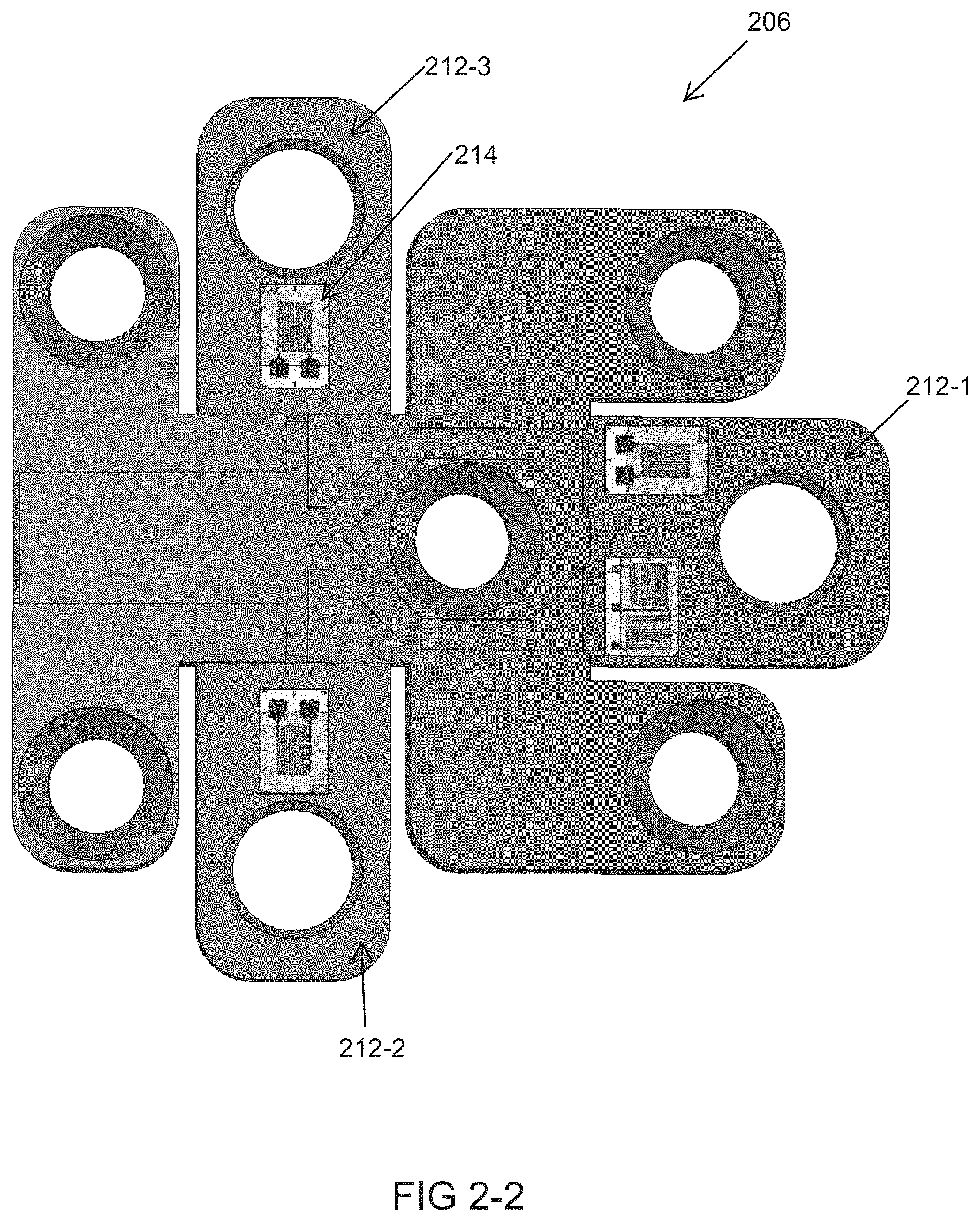
FIG. 2-2 is a bottom view of the sensor platform 206 of FIG. 2-1, according to at least one embodiment of the present disclosure. In some embodiments, the sensor platform 206 may include at least one sensor 214 on a top and a bottom of the sensor platform 206. For example, a first sensor may be placed on a top of the sensor platform 206 (as shown in FIG. 2-1), and a paired sensor may be placed on a bottom of the sensor. In some embodiments, the top and/or the bottom of the sensor platform 206 has more than one sensor 214.
In some embodiments, similar sensors 214 are placed opposite each other on the same cleat support 212-1, 212-2, 212-3 to form a sensor pair or a plurality of sensor pairs. For example, a quarter bridge strain gauge sensor 214 may be placed in the same location on the top and bottom of the front cleat support 212-1, such that a line drawn vertically through the first cleat support 212-1 would intersect a first quarter bridge strain gauge sensor 214 on the top of the first cleat support 212-1 and a second quarter bridge strain gauge sensor 214 on the bottom of the first cleat support 212-1. Sensor pairs having sensors on opposing top and bottom sides of a cleat support may increase the sensitivity, reduce noise, and produce more reliable readings than having a sensor on just one side of a cleat support.
In some embodiments, a sensor pair is located on the same side of the sensor platform 206. For example, the top of the sensor platform 206 may include a first shear strain gauge sensor 214-4 on a second cleat support 212-2 and a sensor shear strain gauge sensor 214-5 on a third cleat support 212-2. This sensor pair may collect transverse shear forces, with the sensor pair collecting more accurate than a single sensor on a single cleat support. However, power and/or weight considerations may encourage the use of a single sensor on a single cleat support.
Any type of sensor may be paired with and/or placed opposite any other type of sensor. For example, a half bridge strain gauge sensor may be placed opposite another half bridge strain gauge sensor. In other examples, a quarter bridge strain gauge sensor may be placed opposite a half bridge strain gauge sensor. In still other examples, a half bridge strain gauge sensor may be placed opposite a full bridge strain gauge sensor. In some embodiments, sensors placed opposite each other have the same grid orientation. In other embodiments, sensors placed opposite each other have different grid orientations.
In some embodiments, a cycling shoe may be worn and/or used in conjunction with a non-sensing or inactive sensor platform. For example, the sensor platform may lack sensors or lack a communication means to the sensors, such that the platform itself is a placeholder in the pocket of the sole. An inactive sensor platform may be positioned in the sole to provide structural rigidity and/or to modify the structural rigidity of the sole when data collection is not needed.
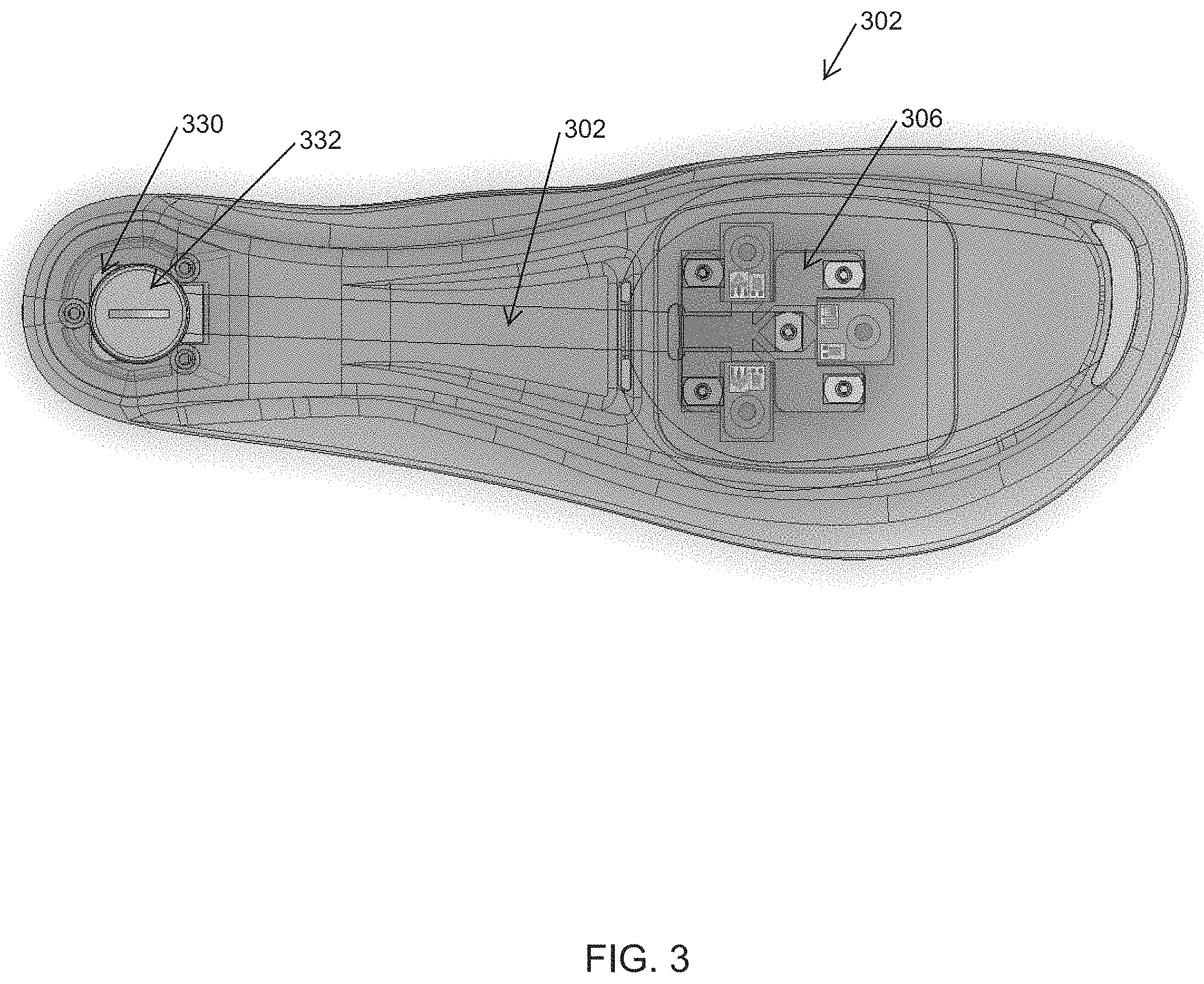
FIG. 3 is a representation of a top view of a sole 302, according to at least one embodiment of the present disclosure. In some embodiments, the sensor platform 306 may be located in the front half of the sole 302, or in other words, in the toe box of the sole 302, or in still other words, in the ball of the sole 302. A battery housing 330 may be located in the rear half of the sole 302, or in other words, a heel of the sole 302. The battery housing 330 may include a battery 332. In other examples, the battery housing 330 and/or battery 332 may be located in the front half of the sole 302. In yet other examples, the battery housing 330 and/or battery 332 may be positioned externally to the sole 302, such as affixed to the upper portion of the cycling shoe.
In other embodiments, the power supply for the sensor platform 306, sensors, processor, storage device, communication device, or other electronic components of the cycling shoe may generate electricity during use. For example, the power supply may include a solar cell positioned on a top of the shoe (i.e., opposite the sole 302) to convert solar radiation to electricity during a ride. In other examples, the sole may include a kinetic energy convertor to convert the cyclic movement of the shoe into an electric current. The power supply may include a moveable weight that, when moved relative to a coil, generates an electrical current.
The battery 332 or other power supply may be connected to the sensor platform 306 via a conduit 333. At least one wire, or a plurality of wires, may connect the battery 332 with the plurality of sensors (e.g., sensors 214 of FIGS. 2-1 and 2-2) on the sensor platform 306. A wire, as used herein, may include a single conductive conduit, a plurality of conductive conduits, a flexible flat cable, a printed circuit board, a flexible printed circuit or another other conductive medium to transmit power to the sensors. In some embodiments, a printed circuit board or flexible printed circuit may include one or more sensors integrated into the printed circuit. In this manner, the plurality of sensors may be powered.
In some embodiments, the battery 332 may be a replaceable battery. In other embodiments, the battery 332 may be a rechargeable battery. The battery 332 may be recharged using any method, including plugging into a standard 120-volt AC outlet via micro-USB or other connection protocol, kinetic movement, solar, and other charging methods.
In some embodiments, the sole 302 includes a processor and a communication device. In some embodiments, the processor and communication device are located on the sensor platform 306. In other embodiments, the processor and communication device are located in the battery housing 330. In still other embodiments, the processor and communication device are located in the arch of the sole 302.
In some embodiments, the processor collects the raw data from the sensors and passes it directly to the communication device. In other embodiments, the processor collects the raw data from the sensors and converts it into a format that is transmitted by the communication device. In still other embodiments, the processor collects and analyzes the raw data from the sensors.
The communication device may be configured to communicate with a computing device using many known communications methods, such as Bluetooth, Wi-Fi, radio frequency, infrared, and other communication methods.
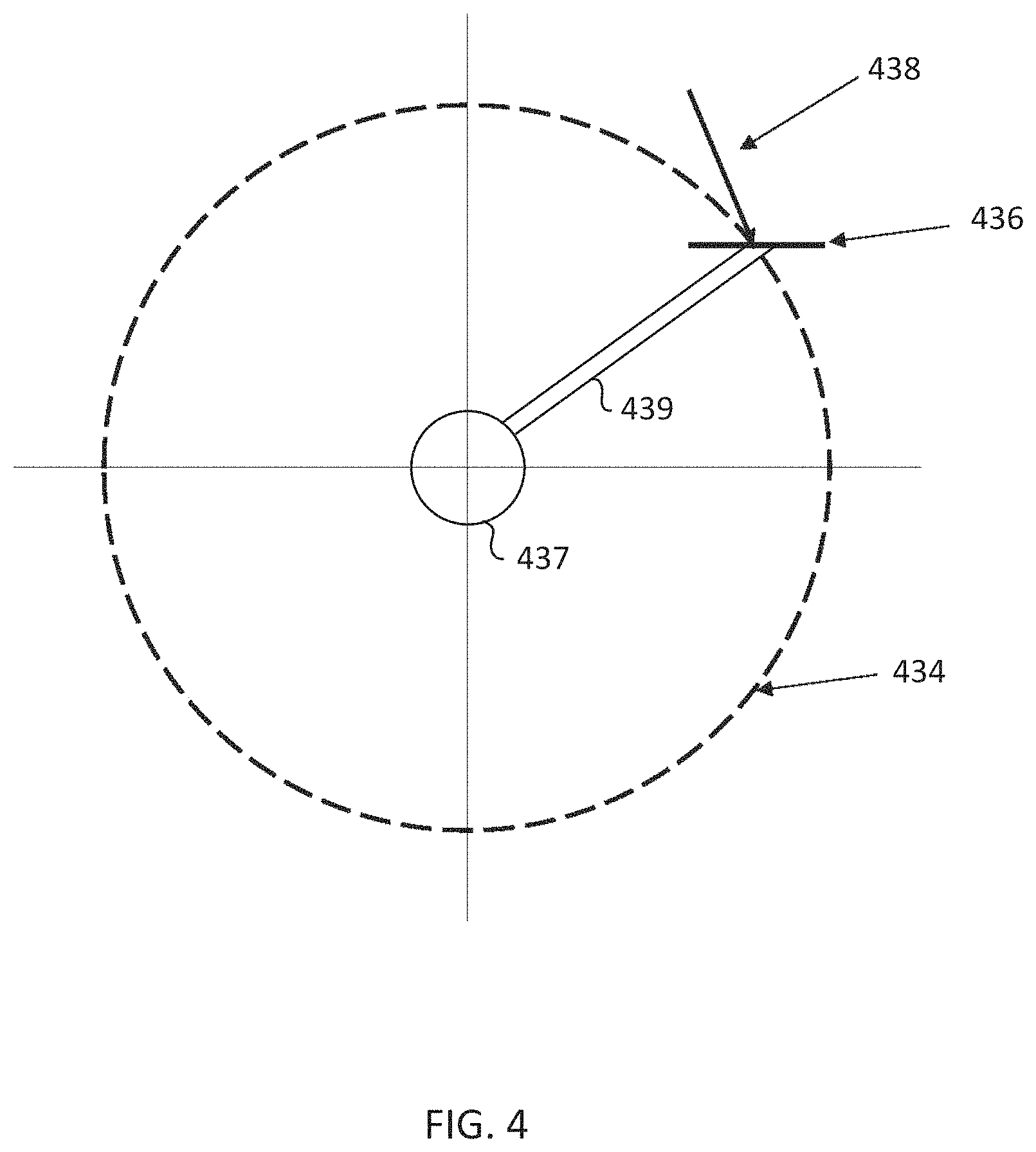
FIG. 4 is a schematic representation of a path 434 that a pedal 436 and/or cycling shoe may travel. The path 434 may be a circular path, or may be an eccentric path, about a rotational axis 437 of the crank 439. A user exerting a force 438 against the pedal 436 may cause the pedal 436 to move along the path 434. The magnitude and direction of the force 438 against the pedal 436 in any location along the path 434 will determine the speed and direction of the pedal 436. To keep the pedal 436 rotating in the same direction, the direction of the force 438 may change along the path 434. Similarly, to move the pedal 436 with a consistent power, the magnitude and direction of the force 438 changes along the path 434. The force 438 applied to the pedal 436 may include components including, relative to the crank, an axial force, a longitudinal shear stress, and a transverse shear stress.
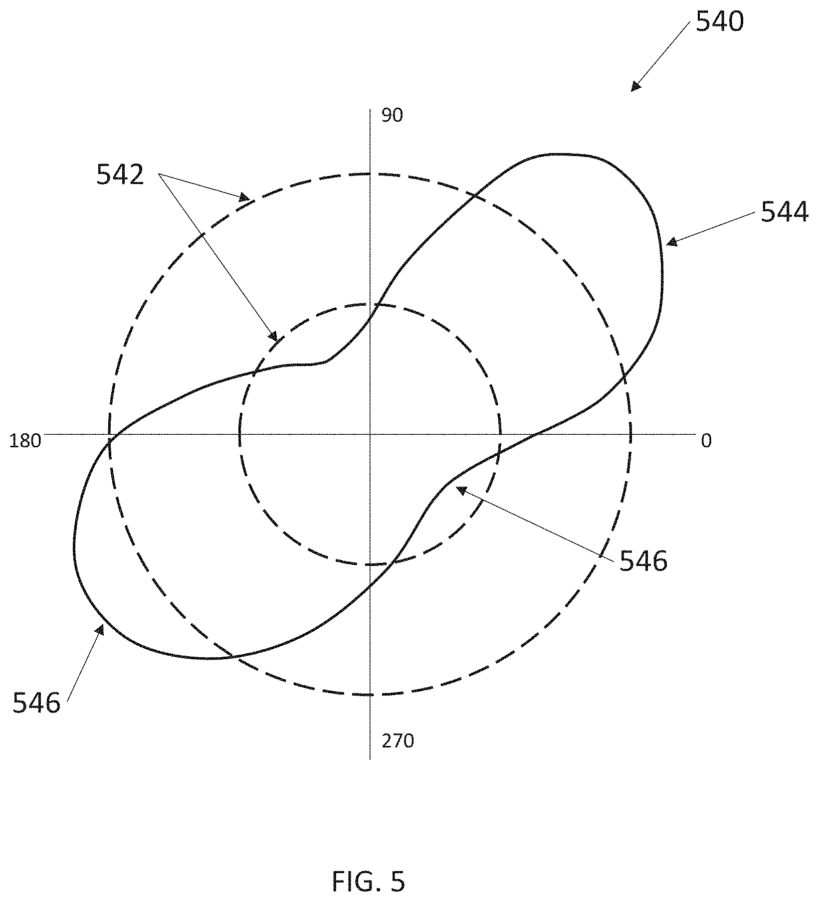
FIG. 5 is a schematic representation of a rotational power chart 540 in polar coordinates, with power shown radially and angle of rotation shown rotationally. The dashed lines 542 represent rotations of the crankset of equal power. The power line 544 represents the power applied to a pedal (such as pedal 436 of FIG. 4) for one full revolution along a path (such as path 434 of FIG. 4). Conventionally, a cyclist does not maintain a constant power throughout the entire pedal stroke. A cycling stroke will have two local minima 546 and two local maxima 548. The location and magnitude of the local minima 546 and local maxima 548 are not only affected by pedal location within the path, but also many user-specific factors, such as pedaling mechanics, strength, weight, aerobic fitness, or any combination of the foregoing. It should be noted that a power line 544 that has a more ovoid shape, where the minimum 546 is has a greater magnitude relative to the local maxima 548, provides more consistent power to the pedal, and therefore indicates more consistent power applied by the cyclist.
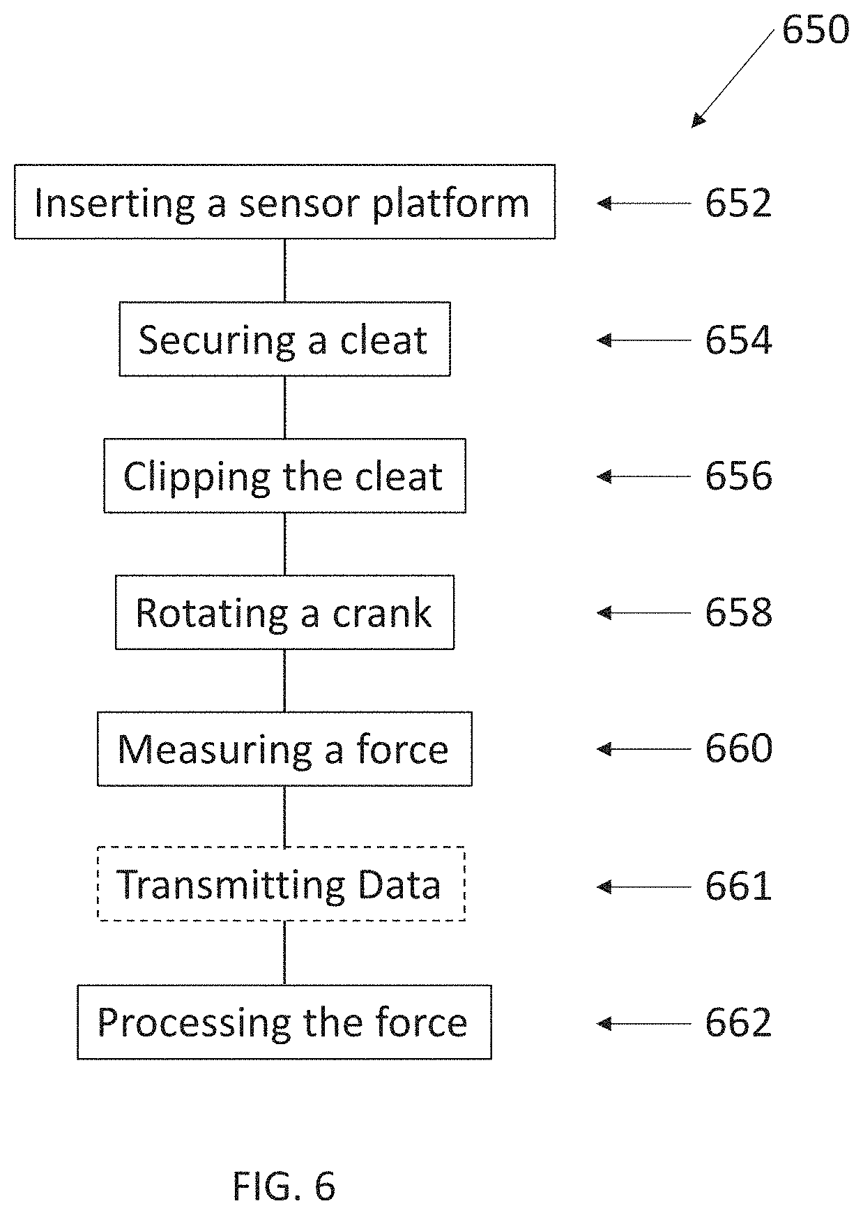
FIG. 6 represents a method 650 for measuring cycling power. The method 650 includes inserting a sensor platform into a pocket at 652. The pocket may be located on the outside of the sole of a cycling shoe. In other examples, the pocket may be located in the sole of the cycling shoe and accessible through the inside of the shoe or through a slot, into with the sensor package may be inserted. A cleat may be secured to the outside of the sole of the cycling shoe at 654. The cleat may be secured using a plurality of cleat fasteners as described herein. In some embodiments, a platform cover is placed between the cleat and the sensor platform, to protect the sensor platform.
The method 650 may include clipping the cleat to a pedal at 656. The pedal may be attached to a crank, which is used to provide the motive force for a bicycle or a torque on a motor or other resistance system of a stationary bicycle. The crank may be rotated by applying a force through the cycling shoe to the pedal at 658. The magnitude of a plurality of components of the force may be measured by sensors on or in the sensor platform positioned between the cycling shoe and the pedal at 660. For example, the sensors of the sensor platform may measure linear forces, shear forces, torque, and other components of the force applied by the user to measure the manner and/or efficiency with which the force is transmitted from the user to the pedal. Upon measuring the force, the data may be optionally transmitted at 661 from the sensors or from the cycling shoe to a remote processor, hardware storage device, or other electronic device. The data may also be retained locally in a memory, processor, or storage device in the cycling shoe.
The magnitude of the measured components of the force is processed and communicated to a computing device at 662. In other embodiments, the measured components of the force are recorded and saved for later analysis. In yet other embodiments, the magnitude of the measured components of the force are presented in real time to a user.
INDUSTRIAL APPLICABILITY
The present disclosure relates generally to devices and methods used to measure force and power of a cyclist's pedal stroke. For example, a cyclist may wear a cycling shoe or a pair of cycling shoes having a sensor platform inserted or embedded into the sole of the cycling shoe. In some embodiments, the cycling shoe may be configured to be used with conventional pedals, or in other words, platform pedals, or pedals that do not clip into a cleat attached to the shoe. For example, such cycling shoes may be used by a mountain biker that does not wish to encumber his feet by clipping into a pedal, but still wishes to analyze the power of his pedal stroke. The sensor platform in such a cycling shoe may assist the cyclist in determining the efficiency of his pedal stroke, the placement of his foot on the pedal, or relative weight distribution on the pedals at different times during the bicycle ride.
In some embodiments, the sensor platform is inserted into the sole of a cycling shoe. A platform cover may cover the sensor platform to protect the sensor platform. In some embodiments, the platform cover may cover the entire pocket and make the pocket waterproof, thereby protecting the sensor platform from water. The platform cover may also protect the sensor platform from impacts, such as when a cyclist attempts to clip into a pedal, but misses and hits the shoe, or when a cyclist is walking while wearing the cycling shoes.
In some embodiments, the cycling shoe may not include a platform cover. For example, a cleat attached to the sensor platform may sufficiently cover the sensor platform to provide the necessary protection. In other examples, the sensor platform may include sensors internal to the sensor platform, such that the sensors are not exposed and vulnerable to damage. In still other examples, the pocket may be contained within the sole, and include a slot into which the sensor platform is inserted. In other embodiments, a platform cover may be used without an active sensor platform, with a non-sensing or inactive platform in place.
In some embodiments, all or part of the sole may be fabricated from a light-weight composite, such as carbon fiber or fiberglass. In other embodiments, all or part of the sole may be fabricated from a light-weight plastic, such as Nylon, PVC, TPU, or other light-weight plastic. In some embodiments, all or part of the sensor platform may be fabricated from a light-weight composite, such as carbon fiber or fiberglass. In other embodiments, all or part of the sensor platform may be fabricated from a composite, such as fiberglass or carbon fiber; a light-weight plastic, such as Nylon, PVC, TPU, or other light-weight plastic; or metal, such as steel, stainless steel, aluminum alloy, or titanium alloy.
A cleat may be installed onto the sole of the cycling shoe to secure the sensor platform and/or the platform cover. The cleat may be configured to clip into a matching pedal. A user wearing the cycling shoe may pedal a bicycle or stationary exercise bicycle by applying force to the shoe, through the sole, the sensor platform and/or the platform cover, to the cleat and to the pedal. The pedal is rotatably attached to a crank, which is rotationally fixed to a front cassette. A chain may connect the front cassette to a rear cassette rotationally fixed to a wheel.
A tangential force applied to the crank through the pedal will rotate the crank, which will rotate the front cassette, and through the chain, rotate the rear cassette to cause the wheel to rotate. The force a cyclist applies to the pedal over a period of time to cause the rotation is the cycling power, commonly measured in Watts (W).
Cycling power may be increased by maximizing the force applied at each stage of the pedal stroke. This may include pushing downward through the front of a pedal stroke, laterally pulling and pushing (sometimes described as scraping) through the top and bottom of a pedal stroke, and lifting through the back of a pedal stroke. One way to quantitatively analyze a cyclist's pedal stroke is to measure his power throughout the pedal stroke. Thus, they can analyze their pedal stroke and make efforts to improve it.
Installing a sensor platform in a cycling shoe may allow a user to measure power applied throughout the pedal stroke. Generally, a force measured closer to its source (e.g., the foot) will be more accurate than one measured further away from the source. Therefore, a sensor installed on the crank will be generally less accurate than a sensor installed on a pedal, which will be generally less accurate than a sensor installed in the sole of a cycling shoe. This decrease in accuracy may occur at least in part because of the losses that may occur as the force transfers from the shoe to the pedal to the crank. Therefore, by installing the sensor platform in the sole of the cycling shoe, the sensor platform is collecting accurate power information close the foot of the user. Additionally, the pedal and crank are rigid structures that transmit power relatively efficiently. The transmission of power from the shoe to the pedal exhibits greater variation than the transmission of power from the pedal to the crankset.
Having multiple sensors on the sensor platform may increase the accuracy and/or amount of the power information collected. For example, by including force measurements on a forward and two rear cleat supports, the force applied to each point of contact of the cleat with the cycling shoe may be measured, thus enabling a user to analyze force distribution between the three cleat supports. Similarly, the bending moment may be calculated for each of the cleat supports, which may allow a user or a manufacturer to understand if energy is being wasted when transferred from the cycling shoe to the cleat and the pedal. Using this feedback, a manufacturer may optimize the structure of a cycling shoe for optimal force transfer and weight distribution.
Similarly, by placing shear stress sensors in the two rear cleat supports, the transverse shear stress, or shear stress in a direction that is not axial with the crank or tangential to the path of the pedal, may be measured and calculated. Transverse shear may help a cyclist understand the extent of transverse or lateral motion or force by her foot. By understanding the location and magnitude of transverse shear, a cyclist may work to improve her stance, her pedal stroke, or may encourage her to find different or better fitting gear (such as pedals, cycling shoes, and cleats).
Placing sensors on both the top and the bottom of the sensor platform may allow for the collection of more accurate and/or additional readings. For example, by comparing measurements from opposing sensors (e.g., sensors in the same location on the top and on the bottom of the sensor platform), the noise from the sensors may be reduced. Further, having opposing sensors may improve the reliability of the system because, if one sensor fails, data will still be collected by a backup sensor.
The type of sensor used may affect both the accuracy and power usage of the sensor. For example, a half or full bridge strain gauge sensor may collect more accurate measurements but may utilize more power.
In some embodiments, the sensors may periodically or regularly take measurements according to a measuring rate. In some embodiments, the measuring rate may be in a range having an upper value, a lower value, or upper and lower values including any of 10 measurements per second, 50 measurements per second, 100 measurements per second, 200 measurements per second, 300 measurements per second, 400 measurements per second, 500 measurements per second, 600 measurements per second, 700 measurements per second, 800 measurements per second, 900 measurements per second, 1,000 measurements per second, or any values therebetween. For example, the measuring rate may be greater than 10 measurements per second. In other examples, the measuring rate may be less than 1,000 measurements per second. In yet other examples, the measuring rate may be in a range of 10 measurements per second to 1,000 measurements per second. A higher measuring rate may provide greater resolution for a power chart but will take more power to collect.
In some embodiments, the measurement collected by the sensors may be converted to a force in Newtons (N). The force multiplied by the distance over which the force is applied in meters (m) and divided by the time interval (s) will provide the power in Watts (W=N m/s). In some embodiments, the sensors of the sensor platform may be configured to measure cycling power in a range having an upper value, a lower value, or upper and lower values including any of 0 W, 50 W, 100 W, 200 W, 400 W, 600 W, 800 W, 1,000 W, 1,200 W, 1,400 W, 1,600 W, 1,800 W, 2,000 W, or any values therebetween. For example, the sensors of the sensor platform may be configured to measure cycling power of at least 400 W. Sensors configured to measure a cycling power of at least 400 W may accurately measure the cycling power of a recreational rider with a sustained cycling power between 200 and 300 W. In other examples, the sensors of the sensor platform may be configured to measure cycling power of at least 1,000 W. Sensors configured to measure a cycling power of at least 1,000 W may accurately measure the cycling power of a professional rider with a sprint cycling power between 500 and 1,000 W. In yet other examples, the sensors of the sensor platform may be configured to measure cycling power of at least 2,000 W. Sensors configured to measure a cycling power of at least 2,000 W may accurately measure the cycling power of a professional rider with a burst cycling power over 1,000 W.
The temperatures to which the sensor platform is exposed vary. By installing sensors that are specially designed, applied, and/or manufactured for a specific material and/or geometry of a sensor platform, the effects of thermal expansion and contraction may be minimized. Similarly, sensors may include "dummy" circuits that only measure the effect of temperature, thereby minimizing the effects of thermal expansion and contraction. For example, a dummy circuit may be oriented along an axis that will experience limited strain. Cyclists ride in a variety of conditions, from extreme heat (e.g., over 40.degree. C.), to extreme cold (e.g., below 0.degree. C.), sometimes changing from one extreme to the other within the same bicycle ride. Thus, having sensors that compensate for temperature will help to reduce erroneous readings and improve the accuracy of the sensor.
In some embodiments, the cycling shoe may include a data logger. In this manner, the data collected from the sensors during a bicycle ride may be collected and analyzed after the ride is completed. Including a data logger, rather than a communication device, may reduce the weight and/or power requirements of a power measurement system.
In other embodiments, the cycling shoe may include a processor and communication device. The data measured by the sensors may be collected by the processor and packaged for transmission to a remote device via the communication device. The data may be transmitted with a transmission rate. In some embodiments, the transmission rate may be the same as the measuring rate. In other embodiments, the transmission rate may be less than the measuring rate. For example, multiple measurements may be taken by the plurality of sensors, collected by the processor, and then packaged together for communication to the remote device. The remote device may then take and process the communicated data. Processing the communicated data may include converting the raw data collected into forces and power. Processing the communicated data may also include developing a power chart, communicating training information to the user, or other information to the user. In some embodiments, the remote device may be a smartphone, a smart watch, a tablet, a laptop or desktop computer, a bicycle computer, a stationary bicycle console, or other remote device.
In some embodiments, the remote device may communicate with or access user profiles with exercise routines specific to the selected user. An example of a user profile database that may be compatible with the principles described herein includes an iFit program available through www.ifit.com and administered through ICON Health and Fitness, Inc., located in Logan, Utah, U.S.A. An example of a program that may be compatible with the principles described in this disclosure is described in U.S. Pat. No. 7,980,996 issued to Paul Hickman. U.S. Pat. No. 7,980,996 is herein incorporated by reference for all that it discloses. However, such profile information may be available through other types of programs that contain such information. For example, such information may be gleaned from social media websites, blogs, government databases, private databases, other sources, or combinations thereof. In some examples, the user information accessible through the user profiles includes the user's age, gender, body composition, height, weight, health conditions, other types of information, or combinations thereof that may be helpful in determining the appropriate exercise routine for the user. Such user profile information may be available to the remote device through the iFit.
The articles "a," "an," and "the" are intended to mean that there are one or more of the elements in the preceding descriptions. The terms "comprising," "including," and "having" are intended to be inclusive and mean that there may be additional elements other than the listed elements. Additionally, it should be understood that references to "one embodiment" or "an embodiment" of the present disclosure are not intended to be interpreted as excluding the existence of additional embodiments that also incorporate the recited features. For example, any element described in relation to an embodiment herein may be combinable with any element of any other embodiment described herein. Numbers, percentages, ratios, or other values stated herein are intended to include that value, and also other values that are "about" or "approximately" the stated value, as would be appreciated by one of ordinary skill in the art encompassed by embodiments of the present disclosure. A stated value should therefore be interpreted broadly enough to encompass values that are at least close enough to the stated value to perform a desired function or achieve a desired result. The stated values include at least the variation to be expected in a suitable manufacturing or production process, and may include values that are within 5%, within 1%, within 0.1%, or within 0.01% of a stated value.
A person having ordinary skill in the art should realize in view of the present disclosure that equivalent constructions do not depart from the spirit and scope of the present disclosure, and that various changes, substitutions, and alterations may be made to embodiments disclosed herein without departing from the spirit and scope of the present disclosure. Equivalent constructions, including functional "means-plus-function" clauses are intended to cover the structures described herein as performing the recited function, including both structural equivalents that operate in the same manner, and equivalent structures that provide the same function. It is the express intention of the applicant not to invoke means-plus-function or other functional claiming for any claim except for those in which the words `means for` appear together with an associated function. Each addition, deletion, and modification to the embodiments that falls within the meaning and scope of the claims is to be embraced by the claims.
It should be understood that any directions or reference frames in the preceding description are merely relative directions or movements. For example, any references to "front" and "back" or "top" and "bottom" or "left" and "right" are merely descriptive of the relative position or movement of the related elements.
The present disclosure may be embodied in other specific forms without departing from its spirit or characteristics. The described embodiments are to be considered as illustrative and not restrictive. The scope of the disclosure is, therefore, indicated by the appended claims rather than by the foregoing description. Changes that come within the meaning and range of equivalency of the claims are to be embraced within their scope.
By way of example, cycling shoes according to the present disclosure may be described according to any of the following sections: 1. A device for measuring exercise power comprising: a shoe having a sole, wherein the sole includes a pocket on an outside surface of the sole; and a sensor platform having a top and a bottom, the sensor platform including a plurality of sensors, a first sensor of the plurality of sensors being on the top of the sensor platform, and a second sensor of the plurality of sensors being on the bottom of the sensor platform, wherein the sensor platform is configured to be placed within the pocket. 2. The device of section 1, wherein the first sensor and the second sensor are force sensors. 3. The device of either section 1 or 2, wherein the sensor platform includes a plurality of cleat supports, the first sensor and the second sensor being located on at least one cleat support of the plurality of cleat supports. 4. The device of section 3, wherein the plurality of cleat supports includes a forward cleat support, a first rear cleat support and a second rear cleat support, wherein a third sensor of the plurality of sensors is configured to measure transverse shear force and located on the first rear cleat support, and a fourth sensor of the plurality of sensors is configured to measure transverse shear force and located on the second rear cleat support. 5. The device of any of sections 1-3, wherein the plurality of sensors includes a plurality of sensor pairs, each sensor pair including a top sensor located on the top of the sensor platform and a bottom sensor located on the bottom of the sensor platform, the top sensor and the bottom sensor being opposite each other on the platform. 6. The device of section 5, wherein the top sensor and the bottom sensor are strain gauges having the same orientation. 7. The device of any of sections 1-6, further comprising a battery located in the sole of the shoe. 8. The device of any of sections 1-7, further comprising a processor located in a heel of the shoe, the processor connected to the plurality of sensors by at least one wire. 9. A system for measuring cycling power comprising: a cycling shoe having a sole; a sensor platform fastened to an outside of the sole using a plurality of platform fasteners, wherein a plurality of sensors are attached to the sensor platform; and a cleat attached to the sole with a plurality of cleat fasteners and configured to secure the sensor platform to the cycling shoe and releasably connect to a bicycle pedal. 10. The system of section 9, wherein the cleat is connected to the sole using three cleat fasteners. 11. The system of section 10, wherein the sensor platform includes three cleat supports, wherein each cleat support includes at least one sensor of the plurality of sensors. 12. The system of any of sections 9-11, further comprising a communication device in electronic communication with the plurality of sensors. 13. A method for measuring cycling power comprising: inserting a sensor platform having a plurality of sensors into a pocket located on an outer surface of a sole of a cycling shoe; securing a cleat to the sole using a plurality of cleat fasteners; clipping the cleat to a pedal attached to a crank; rotating the crank by applying a force through the cycling shoe to the pedal; and measuring a magnitude of a plurality of components of the force using the plurality of sensors on the sensor platform. 14. The method of section 13, further comprising securing the sensor platform to the cycling shoe using a plurality of platform fasteners. 15. The method of section 13 or 14, wherein measuring the magnitude of a plurality of components of the force includes measuring the magnitude of the force periodically according to a measuring rate. 16. The method of section 15, wherein the measuring rate is greater than 10 measurements per second. 17. The method of any of sections 13 through 16, wherein measuring the magnitude of a plurality of components of the force includes measuring the magnitude with at least one of the plurality of sensors located on a top of the sensor platform and at least one of the plurality of sensors located on a bottom of the sensor package. 18. The method of any of sections 13 through 17, wherein measuring the magnitude of a plurality of components of the force includes measuring, relative to the crank, a radial force in line with the crank, a longitudinal shear stress, and a transverse shear stress. 19. The method of any of sections 13 through 18, further comprising processing the magnitude of a plurality of components of the force. 20. The method of any of sections 13 through 19, further comprising communicating the magnitude of a plurality of components of the force to a remote device.
* * * * *
References
D00000
D00001
D00002
D00003
D00004
D00005
D00006
D00007
D00008
D00009
XML
uspto.report is an independent third-party trademark research tool that is not affiliated, endorsed, or sponsored by the United States Patent and Trademark Office (USPTO) or any other governmental organization. The information provided by uspto.report is based on publicly available data at the time of writing and is intended for informational purposes only.
While we strive to provide accurate and up-to-date information, we do not guarantee the accuracy, completeness, reliability, or suitability of the information displayed on this site. The use of this site is at your own risk. Any reliance you place on such information is therefore strictly at your own risk.
All official trademark data, including owner information, should be verified by visiting the official USPTO website at www.uspto.gov. This site is not intended to replace professional legal advice and should not be used as a substitute for consulting with a legal professional who is knowledgeable about trademark law.