Systems and methods for reducing runaway resistance on an exercise device
Powell , et al. Feb
U.S. patent number 10,207,148 [Application Number 15/730,516] was granted by the patent office on 2019-02-19 for systems and methods for reducing runaway resistance on an exercise device. This patent grant is currently assigned to ICON Health & Fitness, Inc.. The grantee listed for this patent is ICON Health & Fitness, Inc.. Invention is credited to Dale Alan Buchanan, Wade A. Powell.


| United States Patent | 10,207,148 |
| Powell , et al. | February 19, 2019 |
Systems and methods for reducing runaway resistance on an exercise device
Abstract
A treadmill may include a deck, a first pulley incorporated into the deck, a second pulley incorporated into the deck, a tread belt surrounding the first pulley and the second pulley, a motor in mechanical communication with at least one of the first pulley and the second pulley to move the tread belt in a first direction, and a runaway mitigation mechanism in at least indirect mechanical communication with the motor. The runaway mitigation mechanism at least mitigates a motor runaway condition.
| Inventors: | Powell; Wade A. (Logan, UT), Buchanan; Dale Alan (Nibley, UT) | ||||||||||
|---|---|---|---|---|---|---|---|---|---|---|---|
| Applicant: |
|
||||||||||
| Assignee: | ICON Health & Fitness, Inc.
(Logan, UT) |
||||||||||
| Family ID: | 61829523 | ||||||||||
| Appl. No.: | 15/730,516 | ||||||||||
| Filed: | October 11, 2017 |
Prior Publication Data
| Document Identifier | Publication Date | |
|---|---|---|
| US 20180099181 A1 | Apr 12, 2018 | |
Related U.S. Patent Documents
| Application Number | Filing Date | Patent Number | Issue Date | ||
|---|---|---|---|---|---|
| 62407073 | Oct 12, 2016 | ||||
| Current U.S. Class: | 1/1 |
| Current CPC Class: | A63B 22/0023 (20130101); H02P 1/00 (20130101); A63B 21/00076 (20130101); A63B 21/0084 (20130101); A63B 24/00 (20130101); A63B 24/0087 (20130101); A63B 71/0622 (20130101); A63B 21/0125 (20130101); A63B 22/02 (20130101); A63B 24/0062 (20130101); A63B 69/0028 (20130101); A63B 21/0051 (20130101); A63B 22/0235 (20130101); A63B 69/0035 (20130101); A63B 22/00 (20130101); H02H 7/0844 (20130101); A63B 2071/063 (20130101); A63B 2220/18 (20130101); A63B 2220/833 (20130101); A63B 2071/0081 (20130101); A63B 2220/72 (20130101); A63B 22/025 (20151001); A63B 2225/50 (20130101); A63B 22/0242 (20130101); A63B 2220/10 (20130101); A63B 2220/30 (20130101); A63B 2225/09 (20130101) |
| Current International Class: | A63B 24/00 (20060101); A63B 21/012 (20060101); A63B 21/008 (20060101); A63B 21/005 (20060101); A63B 69/00 (20060101); A63B 22/00 (20060101); A63B 21/00 (20060101); H02H 7/08 (20060101); A63B 22/02 (20060101); A63B 71/06 (20060101); A63B 71/00 (20060101) |
References Cited [Referenced By]
U.S. Patent Documents
| 4749181 | June 1988 | Pittaway |
| 5409435 | April 1995 | Daniels |
| 5476430 | December 1995 | Lee et al. |
| 6042513 | March 2000 | Koteles |
| 6676569 | January 2004 | Radow |
| 8395366 | March 2013 | Uno |
| 8480541 | July 2013 | Brunts |
| 8506370 | August 2013 | Homsi |
| 8550962 | October 2013 | Piaget et al. |
| 8602951 | December 2013 | Morris |
| 2006/0276306 | December 2006 | Pan et al. |
| 2007/0010383 | January 2007 | Pertegaz-Esteban |
| 2007/0015636 | January 2007 | Molter |
| 2007/0037667 | February 2007 | Gordon |
| 2008/0001772 | January 2008 | Saito |
| 2008/0020898 | January 2008 | Pyles et al. |
| 2008/0020907 | January 2008 | Lin |
| 2008/0032871 | February 2008 | Yeh |
| 2008/0096745 | April 2008 | Perry |
| 2008/0190745 | August 2008 | Taniguchi et al. |
| 2008/0214358 | September 2008 | Ogg et al. |
| 2008/0242511 | October 2008 | Munoz et al. |
| 2008/0312048 | December 2008 | Cassano |
| 2009/0111665 | April 2009 | Wang |
| 2009/0118098 | May 2009 | Yeh |
| 2009/0124464 | May 2009 | Kastelic |
| 2009/0137367 | May 2009 | Hendrickson |
| 2009/0156363 | June 2009 | Guidi et al. |
| 2009/0163327 | June 2009 | Huang et al. |
| 2009/0227424 | September 2009 | Hirata et al. |
| 2009/0227432 | September 2009 | Pacheco |
| 2009/0232420 | September 2009 | Eisenberg et al. |
| 2009/0240858 | September 2009 | Takebayashi |
| 2009/0246746 | October 2009 | Roerdink et al. |
| 2009/0253554 | October 2009 | Mcintosh |
| 2009/0258710 | October 2009 | Quatrochi et al. |
| 2009/0258763 | October 2009 | Richter |
| 2009/0269728 | October 2009 | Verstegen et al. |
| 2009/0286653 | November 2009 | Wiber |
| 2009/0293319 | December 2009 | Avni |
| 2009/0312158 | December 2009 | Trevino et al. |
| 2010/0015585 | January 2010 | Baker |
| 2010/0016127 | January 2010 | Farnsworth et al. |
| 2010/0022354 | January 2010 | Fisher |
| 2010/0024590 | February 2010 | O'neill |
| 2010/0032533 | February 2010 | Chen et al. |
| 2010/0035726 | February 2010 | Fisher et al. |
| 2010/0041516 | February 2010 | Kodama |
| 2010/0048358 | February 2010 | Tchao et al. |
| 2010/0062904 | March 2010 | Crawford et al. |
| 2010/0062914 | March 2010 | Splane |
| 2010/0063426 | March 2010 | Planke |
| 2010/0064255 | March 2010 | Rottler et al. |
| 2010/0079291 | April 2010 | Kroll et al. |
| 2010/0081548 | April 2010 | Labedz |
| 2010/0087298 | April 2010 | Zaccherini |
| 2010/0099541 | April 2010 | Patel |
| 2010/0105527 | April 2010 | Johnson |
| 2010/0113223 | May 2010 | Chiles et al. |
| 2010/0125026 | May 2010 | Zavadsky et al. |
| 2010/0130337 | May 2010 | Stewart |
| 2010/0137105 | June 2010 | McLaughlin |
| 2010/0144501 | June 2010 | Berhanu |
| 2010/0156625 | June 2010 | Ruha |
| 2010/0167883 | July 2010 | Grind |
| 2010/0173276 | July 2010 | Vasin |
| 2010/0173755 | July 2010 | P Erez De Lazarraga |
| 2010/0175634 | July 2010 | Chang et al. |
| 2010/0184568 | July 2010 | Schippers |
| 2010/0190615 | July 2010 | Baker et al. |
| 2010/0192715 | August 2010 | Vauchel et al. |
| 2010/0197462 | August 2010 | Piane, Jr. |
| 2010/0197465 | August 2010 | Stevenson |
| 2010/0210418 | August 2010 | Park |
| 2010/0216599 | August 2010 | Watterson |
| 2010/0216600 | August 2010 | Noffsinger |
| 2010/0216607 | August 2010 | Mueller |
| 2010/0222179 | September 2010 | Temple et al. |
| 2010/0222182 | September 2010 | Park |
| 2010/0227740 | September 2010 | Liu |
| 2010/0235667 | September 2010 | Mucignat et al. |
| 2010/0240458 | September 2010 | Gaiba et al. |
| 2010/0248899 | September 2010 | Bedell et al. |
| 2010/0255959 | October 2010 | Dalebout et al. |
| 2010/0267524 | October 2010 | Stewart et al. |
| 2010/0279822 | November 2010 | Ford |
| 2010/0285933 | November 2010 | Nalley |
| 2010/0289466 | November 2010 | Telefus |
| 2010/0289772 | November 2010 | Miller |
| 2010/0292050 | November 2010 | DiBenedetto et al. |
| 2010/0304931 | December 2010 | Stumpf |
| 2010/0304932 | December 2010 | Kolman et al. |
| 2010/0311552 | December 2010 | Sumners |
| 2011/0003664 | January 2011 | Richard |
| 2011/0021319 | January 2011 | Nissila et al. |
| 2011/0028282 | February 2011 | Sbragia |
| 2011/0034300 | February 2011 | Hall |
| 2011/0054359 | March 2011 | Sazonov et al. |
| 2011/0056328 | March 2011 | Ko |
| 2011/0061840 | March 2011 | Goldmann |
| 2011/0065371 | March 2011 | Leff |
| 2011/0065373 | March 2011 | Goldmann |
| 2011/0067361 | March 2011 | Sloan |
| 2011/0073743 | March 2011 | Shamie |
| 2011/0077055 | March 2011 | Pakula et al. |
| 2011/0082013 | April 2011 | Bastian |
| 2011/0086707 | April 2011 | Loveland |
| 2011/0087137 | April 2011 | Hanoun |
| 2011/0087445 | April 2011 | Sobolewski |
| 2011/0087446 | April 2011 | Redmond |
| 2011/0093100 | April 2011 | Ramsay |
| 2011/0098157 | April 2011 | Whalen et al. |
| 2011/0098615 | April 2011 | Whalen et al. |
| 2011/0109283 | May 2011 | Kapels et al. |
| 2011/0112771 | May 2011 | French |
| 2011/0118089 | May 2011 | Ellis |
| 2011/0124466 | May 2011 | Nishimura |
| 2011/0124476 | May 2011 | Holley |
| 2011/0131005 | June 2011 | Ueshima et al. |
| 2011/0136627 | June 2011 | Williams |
| 2011/0143769 | June 2011 | Jones et al. |
| 2011/0143898 | June 2011 | Trees |
| 2011/0152037 | June 2011 | Tsou |
| 2011/0152038 | June 2011 | Freitag |
| 2011/0152039 | June 2011 | Hendrickson et al. |
| 2011/0152635 | June 2011 | Morris et al. |
| 2011/0172060 | July 2011 | Morales et al. |
| 2011/0175744 | July 2011 | Englert et al. |
| 2011/0181420 | July 2011 | Mack et al. |
| 2011/0188269 | August 2011 | Hosotani |
| 2011/0197157 | August 2011 | Hoffman et al. |
| 2011/0199799 | August 2011 | Hui et al. |
| 2011/0201481 | August 2011 | Lo |
| 2011/0202236 | August 2011 | Galasso et al. |
| 2011/0205164 | August 2011 | Hansen et al. |
| 2011/0221672 | September 2011 | Osterhout et al. |
| 2011/0247530 | October 2011 | Coffman |
| 2011/0252597 | October 2011 | Burris et al. |
| 2011/0257797 | October 2011 | Burris et al. |
| 2011/0269517 | November 2011 | Englert et al. |
| 2011/0269604 | November 2011 | Tseng |
| 2011/0275482 | November 2011 | Brodess et al. |
| 2011/0275489 | November 2011 | Apau |
| 2011/0275499 | November 2011 | Eschenbach |
| 2011/0281691 | November 2011 | Ellis |
| 2011/0283188 | November 2011 | Farrenkopf et al. |
| 2011/0283231 | November 2011 | Richstein et al. |
| 2011/0308919 | December 2011 | Hahn |
| 2011/0312473 | December 2011 | Chu et al. |
| 2011/0319229 | December 2011 | Corbalis et al. |
| 2012/0004075 | January 2012 | Kissel et al. |
| 2012/0004080 | January 2012 | Webb |
| 2012/0010053 | January 2012 | Bayerlein et al. |
| 2012/0015778 | January 2012 | Lee et al. |
| 2012/0015779 | January 2012 | Powch et al. |
| 2012/0015784 | January 2012 | Reed |
| 2012/0020135 | January 2012 | McCune |
| 2012/0021873 | January 2012 | Brunner |
| 2012/0021875 | January 2012 | Karl |
| 2012/0032896 | February 2012 | Vesely |
| 2012/0071301 | March 2012 | Kaylor et al. |
| 2012/0088633 | April 2012 | Crafton |
| 2012/0088634 | April 2012 | Heidecke |
| 2012/0088640 | April 2012 | Wissink |
| 2012/0116684 | May 2012 | Ingrassia et al. |
| 2012/0132877 | May 2012 | Wang |
| 2012/0133192 | May 2012 | Simpson |
| 2012/0165162 | June 2012 | Lu |
| 2012/0169603 | July 2012 | Peterson et al. |
| 2012/0174833 | July 2012 | Early |
| 2012/0178590 | July 2012 | Lu |
| 2012/0187012 | July 2012 | TeVault et al. |
| 2012/0212505 | August 2012 | Burroughs et al. |
| 2012/0218184 | August 2012 | Wissmar |
| 2012/0230504 | September 2012 | Kuroda |
| 2012/0242774 | September 2012 | Numano et al. |
| 2012/0248263 | October 2012 | Grotenhuis |
| 2012/0252580 | October 2012 | Dugan |
| 2012/0253234 | October 2012 | Yang et al. |
| 2012/0253489 | October 2012 | Dugan |
| 2012/0258433 | October 2012 | Hope et al. |
| 2012/0263892 | October 2012 | Rodgers |
| 2012/0270705 | October 2012 | Lo |
| 2012/0271143 | October 2012 | Aragones et al. |
| 2012/0277040 | November 2012 | Vincent et al. |
| 2012/0277891 | November 2012 | Aragones et al. |
| 2012/0293141 | November 2012 | Zhang et al. |
| 2012/0296455 | November 2012 | Ohnemus et al. |
| 2012/0298017 | November 2012 | Chen |
| 2012/0300515 | November 2012 | Carletti et al. |
| 2012/0319604 | December 2012 | Walters |
| 2012/0326873 | December 2012 | Utter, II |
| 2013/0002533 | January 2013 | Burroughs et al. |
| 2013/0004010 | January 2013 | Royer |
| 2013/0009993 | January 2013 | Horseman |
| 2013/0018494 | January 2013 | Amini |
| 2013/0034671 | February 2013 | George |
| 2013/0035612 | February 2013 | Mason et al. |
| 2013/0040783 | February 2013 | Duda et al. |
| 2013/0041590 | February 2013 | Burich et al. |
| 2013/0041617 | February 2013 | Pease et al. |
| 2013/0044521 | February 2013 | Zhao et al. |
| 2013/0050973 | February 2013 | Rohrbach |
| 2013/0053222 | February 2013 | Lo |
| 2013/0053990 | February 2013 | Ackland |
| 2013/0092647 | April 2013 | Chen |
| 2013/0095959 | April 2013 | Marty |
| 2013/0095978 | April 2013 | Sauter |
| 2013/0130868 | May 2013 | Hou |
| 2013/0130869 | May 2013 | Hou |
| 2013/0139736 | June 2013 | Flaherty |
| 2013/0141235 | June 2013 | Utter, II |
| 2013/0147411 | June 2013 | Pang et al. |
| 2013/0150214 | June 2013 | Wu |
| 2013/0154441 | June 2013 | Redmond |
| 2013/0165297 | June 2013 | Daly |
| 2013/0172152 | July 2013 | Watterson |
| 2013/0182781 | July 2013 | Matsutani |
| 2013/0185003 | July 2013 | Carbeck et al. |
| 2013/0190136 | July 2013 | Watterson |
| 2013/0190657 | July 2013 | Flaction et al. |
| 2013/0196821 | August 2013 | Watterson et al. |
| 2013/0196826 | August 2013 | Colledge |
| 2013/0196827 | August 2013 | Chang |
| 2013/0211858 | August 2013 | Ohnemus et al. |
| 2013/0228063 | September 2013 | Turner |
| 2013/0228422 | September 2013 | Mathieu |
| 2013/0231219 | September 2013 | Huang |
| 2013/0237383 | September 2013 | Chen |
| 2013/0245966 | September 2013 | Burroughs et al. |
| 2013/0263418 | October 2013 | Johnson, Jr. |
| 2013/0267386 | October 2013 | Her |
| 2013/0274040 | October 2013 | Coza et al. |
| 2013/0274069 | October 2013 | Watterson et al. |
| 2013/0274071 | October 2013 | Wang |
| 2013/0280682 | October 2013 | Levine et al. |
| 2013/0324368 | December 2013 | Aragones et al. |
| 2013/0325394 | December 2013 | Yuen et al. |
| 2013/0338802 | December 2013 | Winsper et al. |
| 2013/0346043 | December 2013 | Mewes et al. |
| 2014/0011645 | January 2014 | Johnson et al. |
| 2014/0026788 | January 2014 | Kallio, III et al. |
| 2014/0031703 | January 2014 | Rayner et al. |
| 2014/0039840 | February 2014 | Yuen et al. |
| 2014/0052280 | February 2014 | Yuen et al. |
| 2014/0056461 | February 2014 | Afshar |
| 2014/0073488 | March 2014 | Wu |
| 2014/0080678 | March 2014 | Wu |
| 2014/0085077 | March 2014 | Luna et al. |
| 2014/0100464 | April 2014 | Kaleal et al. |
| 2014/0102340 | April 2014 | Kooistra |
| 2014/0121066 | May 2014 | Huang et al. |
| 2014/0139450 | May 2014 | Levesque et al. |
| 2014/0156228 | June 2014 | Molettiere et al. |
| 2014/0187383 | July 2014 | Martin |
| 2014/0195103 | July 2014 | Nassef |
| 2014/0221160 | August 2014 | Hardy et al. |
| 2014/0222173 | August 2014 | Giedwoyn et al. |
| 2014/0265690 | September 2014 | Henderson |
| 2014/0270375 | September 2014 | Canavan et al. |
| 2014/0274564 | September 2014 | Greenbaum |
| 2014/0274579 | September 2014 | Olson |
| 2014/0360413 | December 2014 | Schenk |
| 2015/0001048 | January 2015 | Koppes et al. |
| 2015/0003621 | January 2015 | Trammell |
| 2015/0004579 | January 2015 | Shelton |
| 2015/0016623 | January 2015 | Trammell |
| 2015/0044648 | February 2015 | White et al. |
| 2015/0048807 | February 2015 | Fan et al. |
| 2015/0065273 | March 2015 | Lake |
| 2015/0065301 | March 2015 | Oteman |
| 2015/0105220 | April 2015 | Hong |
| 2015/0192929 | July 2015 | Rihn et al. |
| 2015/0199494 | July 2015 | Koduri et al. |
| 2015/0201722 | July 2015 | Brouard |
| 2015/0202487 | July 2015 | Wu |
| 2015/0209610 | July 2015 | Dalebout et al. |
| 2015/0209617 | July 2015 | Hsiao |
| 2015/0246751 | September 2015 | Spivack et al. |
| 2015/0250304 | September 2015 | Dalebout |
| 2015/0251047 | September 2015 | Jussi Maanitty |
| 2015/0251048 | September 2015 | Dalebout |
| 2015/0251055 | September 2015 | Ashby |
| 2015/0253210 | September 2015 | Ashby et al. |
| 2015/0265903 | September 2015 | Kolen et al. |
| 2015/0295397 | October 2015 | Lin et al. |
| 2015/0314184 | November 2015 | Moya Saez |
| 2015/0346994 | December 2015 | Chanyontpatanakul |
| 2015/0352396 | December 2015 | Dalebout |
| 2015/0352401 | December 2015 | Johnson |
| 2015/0352402 | December 2015 | Arnold et al. |
| 2015/0367158 | December 2015 | Pretz et al. |
| 2015/0367176 | December 2015 | Bejestan et al. |
| 2016/0008650 | January 2016 | Jue et al. |
| 2016/0016035 | January 2016 | Hao |
| 2016/0027325 | January 2016 | Malhotra |
| 2016/0038785 | February 2016 | Netter |
| 2016/0047446 | February 2016 | Hung |
| 2016/0066818 | March 2016 | Cowley et al. |
| 2016/0096064 | April 2016 | Gatti |
| 2016/0121161 | May 2016 | Mountain |
| 2016/0193518 | July 2016 | Baxter |
| 2016/0211841 | July 2016 | Harrison |
| 2016/0219968 | August 2016 | Martin |
| 2016/0263426 | September 2016 | Mueller et al. |
| 2016/0303421 | October 2016 | Tyger et al. |
| 2016/0317861 | November 2016 | Dalebout |
| 2016/0367851 | December 2016 | Astilean et al. |
| 2017/0056726 | March 2017 | Dalebout et al. |
| 2017/0068782 | March 2017 | Pillai et al. |
| 2017/0113093 | April 2017 | Bellavista et al. |
| 2017/0120102 | May 2017 | Chen |
| 2017/0128784 | May 2017 | Molins et al. |
| 2017/0136280 | May 2017 | Lee |
| 2017/0136288 | May 2017 | Huang |
| 2017/0136289 | May 2017 | Frank |
| 2017/0136291 | May 2017 | Huang |
| 2017/0136339 | May 2017 | Habiche |
| 2017/0165523 | June 2017 | Chou |
| 2017/0189745 | July 2017 | Hamilton et al. |
| 2017/0216660 | August 2017 | Lernihan |
| 2017/0266483 | September 2017 | Dalebout et al. |
| 2017/0266532 | September 2017 | Watterson |
| 2017/0266533 | September 2017 | Dalebout |
| 2017/0266534 | September 2017 | Watterson |
| 2017/0266535 | September 2017 | Watterson |
| 2017/0274242 | September 2017 | Corbalis |
| 2017/0326411 | November 2017 | Watterson |
| 2017/0340917 | November 2017 | Chang |
| 2017/0368442 | December 2017 | Baudhuin |
| 2018/0001135 | January 2018 | Powell |
| 2018/0036585 | February 2018 | Powell |
| 2018/0056111 | March 2018 | Chiang et al. |
| 2018/0092603 | April 2018 | Duan et al. |
| 2018/0099179 | April 2018 | Chatterton et al. |
| 2018/0099180 | April 2018 | Wilkinson |
| 2018/0099181 | April 2018 | Powell et al. |
| 2018/0104533 | April 2018 | Powell et al. |
| 2018/0111018 | April 2018 | Lee |
| 2018/0117385 | May 2018 | Watterson et al. |
| 2018/0117388 | May 2018 | Porter |
| 2018/0117419 | May 2018 | Jackson |
| 2018/0147440 | May 2018 | Lin |
| 2018/0154208 | June 2018 | Powell et al. |
Attorney, Agent or Firm: Ray Quinney & Nebeker
Parent Case Text
RELATED APPLICATIONS
This application claims priority to U.S. Patent Application Ser. No. 62/407,073 titled "Systems and Methods for Reducing Runaway Resistance on an Exercise Device" and filed on 12 Oct. 2016, which application is herein incorporated by reference for all that it discloses.
Claims
What is claimed is:
1. A treadmill, comprising: a deck; a first pulley incorporated into the deck; a second pulley incorporated into the deck; a tread belt surrounding the first pulley and the second pulley; a motor including a drive shaft, wherein the drive shaft is in mechanical communication with at least one of the first pulley and the second pulley to move the tread belt in a first direction; a runaway mitigation mechanism in at least indirect mechanical communication with the motor, the runaway mitigation mechanism including: a container surrounding a portion of the drive shaft; and a fluid within the container; wherein the runaway mitigation mechanism is configured to at least mitigate a motor runaway condition.
2. The treadmill of claim 1, wherein the motor runaway condition is induced when a user moves the tread belt with a force that is greater than that outputted with the motor.
3. The treadmill of claim 2, wherein the user moves the tread belt at the force that is greater than that which is outputted with the motor when an incline angle of the deck exceeds a threshold angle.
4. The treadmill of claim 3, wherein the container is configured to tilt with the deck, and wherein the container is shaped such that the fluid contacts the drive shaft when the deck is disposed at the threshold angle.
5. The treadmill of claim 4, wherein the portion of the drive shaft surrounded by the container further comprises at least one vane.
6. The treadmill of claim 4, wherein the portion of the drive shaft surrounded by the container is fully immersed in the fluid when the deck is oriented at a 12 degree incline.
7. The treadmill of claim 4, wherein the portion of the drive shaft surrounded by the container is partially immersed in the fluid when the deck is oriented at a 9 to 12 degree incline.
8. The treadmill of claim 4, wherein the fluid comprises an oil based fluid.
9. The treadmill of claim 3, wherein the runaway mitigation mechanism is configured to increase a resistance to an operation of the motor when the deck is oriented at the threshold angle that induces the motor runaway condition.
10. The treadmill of claim 3, wherein the threshold angle is over 9 degrees.
11. The treadmill of claim 3, wherein the threshold angle is over 11 degrees.
12. A treadmill, comprising: a deck; a first pulley incorporated into the deck; a second pulley incorporated into the deck; a tread belt surrounding the first pulley and the second pulley; a motor including a drive shaft, wherein the drive shaft is in mechanical communication with at least one of the first pulley and the second pulley; an incline mechanism in mechanical communication with the deck to adjust an incline angle of the deck; and a runaway mitigation mechanism in communication with the motor; wherein the runaway mitigation mechanism is configured to mitigate a motor runaway condition due to the incline angle of the deck; wherein the runaway mitigation mechanism includes: a container surrounding a portion of the drive shaft; a fluid disposed within the container; wherein the container is configured to tilt with the deck; and wherein the container is shaped such that the fluid contacts the drive shaft when the deck is disposed at a threshold angle.
13. The treadmill of claim 12, wherein the portion of the drive shaft surrounded by the container includes at least one vane.
14. The treadmill of claim 12, wherein the portion of the drive shaft surrounded by the container is fully immersed in the fluid when the deck is oriented at a 12 degree incline.
15. The treadmill of claim 12, wherein the motor runaway condition is induced when a user moves the tread belt with a force that is greater than the force outputted with the motor.
16. The treadmill of claim 12, wherein the fluid comprises an oil based fluid.
17. The treadmill of claim 12, wherein the incline angle that induces the motor runaway condition is over 11 degrees.
18. A treadmill, comprising: a deck; a first pulley incorporated into the deck; a second pulley incorporated into the deck; a tread belt surrounding the first pulley and the second pulley; a motor including a drive shaft, wherein the drive shaft is in mechanical communication with at least one of the first pulley and the second pulley; an incline mechanism in mechanical communication with the deck to adjust an incline angle of the deck; a runaway mitigation mechanism in communication with the motor; wherein the runaway mitigation mechanism mitigates a motor runaway condition where the motor runaway condition is induced with the incline angle of the deck; wherein the runaway mitigation mechanism includes: a container that surrounds a portion of the drive shaft; an oil based fluid disposed within the container; and at least one vane formed on the portion of the drive shaft contained within the container; wherein the container is configured to tilt with the deck; wherein the container is shaped such that the fluid contacts the drive shaft when the deck is disposed at a threshold angle; and wherein the drive shaft is fully immersed in the oil based fluid when the deck is oriented at a 12 degree incline.
Description
BACKGROUND
Aerobic exercise is a popular form of exercise that improves one's cardiovascular health by reducing blood pressure and providing other benefits to the human body. Aerobic exercise generally involves low intensity physical exertion over a long duration of time. Typically, the human body can adequately supply enough oxygen to meet the body's demands at the intensity levels involved with aerobic exercise. Popular forms of aerobic exercise include running, jogging, swimming, and cycling, among others activities. In contrast, anaerobic exercise typically involves high intensity exercises over a short duration of time. Popular forms of anaerobic exercise include strength training and short distance running.
Many choose to perform aerobic exercises indoors, such as in a gym or their home. Often, a user will use an aerobic exercise machine to have an aerobic workout indoors. One type of aerobic exercise machine is a treadmill, which is a machine that has a running deck attached to a support frame. The running deck can support the weight of a person using the machine. The running deck incorporates a conveyor belt that is driven by a motor. A user can run or walk in place on the conveyor belt by running or walking at the conveyor belt's speed. The speed and other operations of the treadmill are generally controlled through a control module that is also attached to the support frame and within a convenient reach of the user. The control module can include a display, buttons for increasing or decreasing a speed of the conveyor belt, controls for adjusting a tilt angle of the running deck, or other controls. Other popular exercise machines that allow a user to perform aerobic exercises indoors include elliptical trainers, rowing machines, stepper machines, and stationary bikes, to name a few.
One type of treadmill is disclosed in U.S. Pat. No. 6,042,513 issued to John Koteles, et al. In this reference, a runaway protection mechanism is provided. In use, the electric motor is connected to an electric power source, such as an alternating-current wall outlet. The runaway protection mechanism includes a disconnect mechanism for disconnecting the motor from the electric power source and thereby de-energizing the motor. The runaway protection mechanism further includes a safety mechanism for comparing the actual motor speed with a desired motor speed and activating the disconnect mechanism when the actual speed exceeds the desired speed by a predetermined amount.
SUMMARY
In one embodiment, a treadmill includes a deck, a first pulley incorporated into the deck, a second pulley incorporated into the deck, a tread belt surrounding the first pulley and the second pulley, a motor in mechanical communication with at least one of the first pulley and the second pulley to move the tread belt in a first direction, and a runaway mitigation mechanism in at least indirect mechanical communication with the motor. The runaway mitigation mechanism at least mitigates a motor runaway condition.
The motor runaway condition may be induced when a user moves the tread belt with a force that is greater than that outputted with the motor.
The user may move the tread belt at the force that is greater than that which is outputted with the motor when the incline angle of the deck exceeds a threshold angle.
The runaway mitigation mechanism may include a container of fluid and the motor includes a drive shaft. When the container tilts with the deck at the threshold angle, the fluid may contact the drive shaft, and when the drive shaft is rotating and in contact with the fluid, the fluid may increase a resistance to the rotation of the drive shaft.
The drive shaft may include at least one vane.
The drive shaft may be fully immersed in the fluid when the deck is oriented at a 12 degree incline or greater.
The drive shaft may be partially immersed in the fluid with the deck is oriented at a 9 to 12 degree incline.
The fluid may be an oil based fluid.
The runaway mitigation mechanism may increase a resistance to the operation of the motor when the deck is oriented at the threshold angle that induces the motor runaway condition.
The threshold angle may be over 9 degrees.
The threshold angle may be over 11 degrees.
The runaway mitigation mechanism may include a brake pad.
The runaway mitigation mechanism may include a magnetic mechanism.
In one embodiment, a treadmill may include a deck, a first pulley incorporated into the deck, a second pulley incorporated into the deck, a tread belt surrounding the first pulley and the second pulley, a motor in mechanical communication with at least one of the first pulley and the second pulley, an incline mechanism in mechanical communication with the deck to adjust an incline angle of the deck, and a runaway mitigation mechanism is in communication with the motor. The runaway mitigation mechanism may at least mitigate a motor runaway condition is induced by the incline angle of the deck, and the runaway mitigation mechanism may include a container of fluid. The motor may include a drive shaft. The container may tilt at the incline angle that induces the motor runaway condition so that the fluid contacts the drive shaft. When the drive shaft is rotating and in contact with the fluid, the fluid increases a resistance to the rotation of the drives shaft.
The drive shaft may include at least one vane.
The drive shaft may be fully immersed in the fluid when the deck is oriented at a 12 degree incline.
The motor runaway condition may be induced when a user moves the tread belt with a force that is greater than that outputted with the motor.
The fluid may be an oil based fluid.
The incline angle that may induce the motor runaway condition is over 11 degrees.
In one embodiment, a treadmill may include a deck, a first pulley incorporated into the deck, a second pulley incorporated into the deck, a tread belt surrounding the first pulley and the second pulley, a motor in mechanical communication with at least one of the first pulley and the second pulley, an incline mechanism in mechanical communication with the deck to adjust an incline angle of the deck, and a runaway mitigation mechanism is in communication with the motor. The runaway mitigation mechanism mitigates a motor runaway condition where the motor runaway condition is induced by the incline angle of the deck and the runaway mitigation mechanism includes a container of an oil based fluid. The motor includes a drive shaft, and the drive shaft includes at least one vane. The container tilts at the incline angle that induces the motor runaway condition so that the fluid contacts the drive shaft, and when the drive shaft is rotating and in contact with the fluid, the fluid increases a resistance to the rotation of the drive shaft. The drive shaft is fully immersed in the fluid when the deck is oriented at a 12 degree incline.
BRIEF DESCRIPTION OF THE DRAWINGS
FIG. 1 depicts an example of a treadmill in accordance with aspects of the present disclosure.
FIG. 2 depicts an example of a treadmill in accordance with aspects of the present disclosure.
FIG. 3 depicts an example of a treadmill motor in accordance with aspects of the present disclosure.
FIG. 4 depicts an example of a runaway mitigation mechanism in accordance with aspects of the present disclosure.
FIG. 5 depicts an example of a runaway mitigation mechanism in accordance with aspects of the present disclosure.
FIG. 6 depicts an example of a runaway mitigation mechanism in accordance with aspects of the present disclosure.
FIG. 7 depicts an example of a runaway mitigation mechanism in accordance with aspects of the present disclosure.
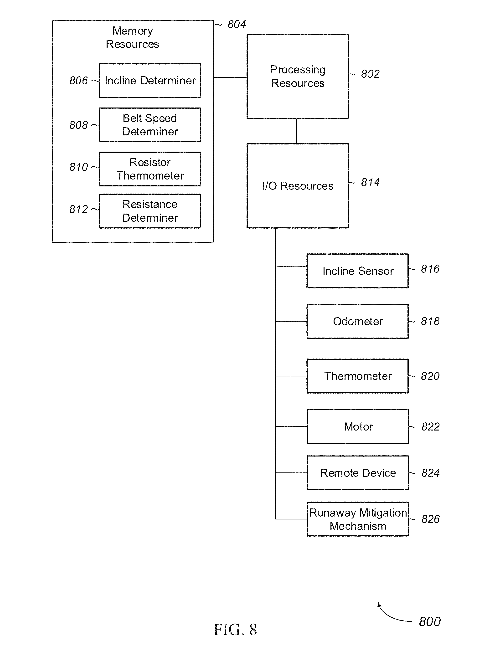
FIG. 8 depicts a block diagram of an example of a runaway mitigation system in accordance with aspects of the present disclosure.
FIG. 9 depicts an example of a method for mitigating runaway on a treadmill motor in accordance with aspects of the present disclosure.
FIG. 10 depicts an example of a method for mitigating runaway on a treadmill motor in accordance with aspects of the present disclosure.
DETAILED DESCRIPTION
For purposes of this disclosure, the term "aligned" means parallel, substantially parallel, or forming an angle of less than 35.0 degrees. For purposes of this disclosure, the term "transverse" means perpendicular, substantially perpendicular, or forming an angle between 55.0 and 125.0 degrees. Also, for purposes of this disclosure, the term "length" means the longest dimension of an object. Also, for purposes of this disclosure, the term "width" means the dimension of an object from side to side. Often, the width of an object is transverse the object's length. For the purposes of this disclosure, an "output speed" generally refers to a speed of the motor's drive shaft that correlates to the amount of electricity supplied to the motor. Such an output speed may be affected, but not controlled, by the mechanical load on the motor because the amount of electricity supplied to the motor may vary, depending on the motor's mechanical load. Additionally, for the purposes of this disclosure, the term "runaway" generally refers to instances where the drive shaft operates at an actual speed that is inconsistent with the motor's output speed. Examples of runaway include where the drive shaft is turned in reverse, the drive shaft rotates at a speed faster than the output speed, other conditions, or combinations thereof. Further, for the purposes of this disclosure, the term "runaway mitigation" may generally refer to at least bringing the output speed and the actual speed of the drive shaft into closer alignment. In some cases, a runaway mitigation mechanism increases a mechanical load on the motor.
FIG. 1 depicts an example of a treadmill 100 having a deck 102 with a first pulley disposed in a front portion of the deck 102 and a second pulley incorporated into a rear portion of the deck 102. A tread belt 104 surrounds the first pulley and the second pulley. A motor is in mechanical communication with either the first pulley or the second pulley. A motor (not shown) drives the tread belt 104. With the deck 102 oriented in a substantially horizontal position, a user's body weight pushes the underside of the tread belt 104 into the deck's upper surface, which generates an amount of friction between the belt and the deck, which friction increases the load on the motor. Additionally, the tread belt also carries the portion of the user's weight along the length of the deck as the motor operates, which also increases the load on the motor.
The rear portion of the deck 102 is attached to a base member 106 of the treadmill's frame. A pivot connection 110 between the rear portion of the deck 102 and the base member 106 allows the front portion of the deck 102 to incline upwards or decline downwards. When the deck 102 inclines or declines, the base member 106 remains stationary.
A first side post 112 is attached to a first side of the base member 106, and a second side post 114 is attached to a second side of the base member 106. In the example depicted in FIG. 1, the first side post 112 and the second side post 114 also remain stationary as the deck 102 inclines and/or declines. The first side post 112 and the second side post 114 collectively support a console 116. The console 116 includes a display 118 and an input mechanism 120 for controlling the deck's incline angle. Additionally, an emergency stop feature 122 may be included on the console.
FIG. 2 depicts an example of a treadmill 200. In this example, the deck 202 is inclined so that the front portion of the deck 202 is elevated. As shown, by the arrow in FIG. 2, the display 204 and emergency stop feature 206 may also be inclined with the front portion of the deck 202. At this inclined angle, the user may perform an exercise on the deck 202. At the inclined angle, gravity pulls on the user's weight, which offsets at least some of the mechanical load on the motor for driving the tread belt as the user pushes against the tread belt during the performance of an exercise. Often, the power supplied to the motor is reduced accordingly, to slow the tread belt and keep the tread belt traveling at the desired, consistent speed. Under these conditions, the tread belt is still traveling at the output speed that is consistent with the amount of electricity supplied to the motor because the amount is reduced to be consistent with the reduced mechanical load. At some angles, the user's body weight applies a force sufficiently large that the motor receives a minimal amount of electrical power to keep the tread belt operating at the output speed.
However, in some circumstances, the angle of the deck, the weight of the user, the friction between the tread belt and the deck, other factors, or combinations thereof, cause the drive shaft's motor to rotate at a faster speed than the output speed. This condition may be referred to as a runaway condition. While this example is described as a runaway condition, in other cases, the runaway condition may be caused by any number of different circumstances. The runaway condition may cause the motor to generate electrical power, heat, and/or cause damage to the motor or other components of the treadmill.
FIG. 3 illustrates an example of a treadmill 302 with a portion of the housing removed for illustrative purposes. Inside the housing, a drive motor 304 is disposed adjacent to a pulley 306 that moves the tread belt 308 in a rotational direction. The drive motor 304 is attached to the pulley 306 by a drive shaft 309. A power supply (not shown) supplies power to the drive motor to drive the rotation of the drive shaft 309. The power supply may be an external source, such as an alternating current system incorporated into a residence or other building, a generator, an alternative power source, another type power source, or combinations thereof. In some instances, the power supply may be internal to the housing and/or treadmill 302. Attached to and coaxial with the drive motor 304 is a flywheel 310. The flywheel 310 rotates with the drive motor 304.
A lift motor 314 is connected to the deck 316 and also to the base frame (not shown) of the treadmill. When activated, the lift motor 314 causes a rod to extend downward, which pushes against the front portion of the deck and the base frame causing the front portion of the deck to raise. In other situations, when the lift motor 314 is activated, the rod is retracted, which causes the front portion of the deck to lower. In these cases, the lift motor 314 may be transversely oriented with respect to the fan assembly 312. While this example has been described as having a lift motor as part of a system for inclining the deck, any appropriate mechanism may be used to incline the deck.
FIG. 4 depicts an example of a runaway mitigation mechanism 400. In this example, the runaway mitigation mechanism 400 includes a container 402 and a portion of the drive shaft 404 partially disposed within the container 402. The container 402 includes a fluid 406, such as an oil-based fluid. In some cases, the container 402 moves with the deck. When the deck is in a level orientation, the container 402 is held at a corresponding orientation. On the other hand, when the deck is inclined at an angle, the container 402 is held in a tilting orientation.
In the level orientation, the fluid 406 resides under the drive shaft 404 without making contact with the drive shaft 404. In the illustrated example, the container 402 includes a trough 408 defined in the far portion 410 of the container 402 where the fluid 406 can pool away from the drive shaft 404. However, in alternative embodiments, no trough is included. In these embodiments, the geometry of the container 402 may be such that the fluid pools away from the drive shaft when the deck is not sufficiently tilted. In other embodiments, the fluid 406 may be stored in a separate reservoir, and selectively introduced to the container 402 via a pump, when a runaway condition is detected.
In the illustrated example, at least one vane 412 is attached to the drive shaft 404. While this example has been depicted with a vane, any appropriate number or shape of vanes may be incorporated into the drive shaft 404.
FIG. 5 depicts an example of a runaway mitigation mechanism 500 where the container 502 is oriented in a tilted orientation. With the container 502 in a tilted orientation, the fluid 504 pools in the proximity of the drive shaft 506 so that the fluid 504 is in contact with the drive shaft 506. In the illustrated example, the drive shaft 506 is immersed in the fluid 504 so that an entire circumference of the drive shaft 506 is in contact with the fluid 504. In some examples, the contact with the drive shaft 506 resists rotation of the drive shaft 506. In some cases, the viscosity of the fluid 504 engages and resists the movement of the vanes 508.
FIG. 6 illustrates an example of a runaway mitigation mechanism 600. In this example, a drive shaft 602 extends beyond a motor casing 604, and a rotary disc 606 is rigidly attached to the drive shaft 602. A compression brake 608 is positioned adjacent to the rotary disc 606. The compression brake 608 includes a first pad 610 adjacent a first side of the rotary disc 606, and a second pad 614 adjacent a second side of the rotary disc 606. When activated, the first pad 610 and the second pad 614 move towards the rotary disc 606 simultaneously and apply a compressive load to the rotary disc 606, which resists rotational movement of the rotary disc 606. This increases the mechanical load on the motor because of the increased resistance to rotate the drive shaft 602. Under certain conditions, the compression brake 608 applies a compressive load that is sufficient to prevent the rotary disc 606, and therefore the drive shaft 602, from rotating at all. Under other conditions, the compression brake 608 can apply a compressive load that merely increases the resistance to the rotational movement of the rotary disc 606, but is not sufficient to stop the drive shaft 602 from rotating. When a runaway condition is sensed or at least determined to exist, the compression brake 608 can be activated to increase the mechanical resistance to the motor to at least mitigate the runaway condition.
FIG. 7 depicts an example of a runaway mitigation mechanism 700. In this example, a drive shaft 702 extends beyond a motor casing 704, and a rotary disc 706 is rigidly attached to the drive shaft 702. In the illustrated example, the rotary disc 706 includes at least some magnetically conductive material. A magnetic unit 708 is positioned adjacent to the rim 710 of the rotary disc 706. The magnetic unit 708 can apply a magnetic force on the rotary disc 706 that resists movement of the rotary disc 706 and therefore movement of the drive shaft 702.
The magnetic unit 708 is positionable with a linear actuator 712. The linear actuator 712 includes an actuator motor 714 and a screw rod 716. As the motor operates in a first direction, the screw rod 716 moves the magnetic unit 708 in a direction towards the rotary disc 706. As the motor operates in a second direction, the screw rod 716 moves the magnetic unit 708 in another direction away from the rotary disc 706. As the magnetic unit 708 approaches the rotary disc 706, the magnetic load applied to the rotary disc 706 increases so that more resistance is applied to the rotary disc's movement, and mechanical resistance on the motor increases. As the magnetic unit 708 moves away from the rotary disc 706, the magnetic load on the rotary disc 706 decreases, which lowers mechanical resistance on the motor. In alternative embodiments, the magnetic unit is an electromagnet that produces a magnetic field that is proportional to the power supplied to the magnetic unit. In this example, the magnetic strength applied to the rotary disc is adjustable by varying the power to the magnetic unit.
FIG. 8 illustrates a block diagram of an example of a runaway mitigation system 800, in accordance with the present disclosure. The runaway mitigation system 800 may include a combination of hardware and programmed instructions for executing the functions of the runaway mitigation system 800. In this example, the runaway mitigation system 800 includes processing resources 802 that are in communication with memory resources 804. Processing resources 802 include at least one processor and other resources used to process the programmed instructions. The memory resources 804 represent generally any memory capable of storing data such as programmed instructions or data structures used by the runaway mitigation system 800. The programmed instructions and data structures shown stored in the memory resources 804 include an incline determiner 806, a belt speed determiner 808, a resistor thermometer 810, and a resistance determiner 812.
Input/output (I/O) resources 814 are in communication with the processing resources 802. The I/O resources 814 may include any appropriate type of mechanism for communicating with remote devices. For example, the I/O resources 814 may include a transmitter, a wireless transmitter, a receiver, a transceiver, a port for receiving an external memory, a network interface, another I/O resource, or combinations thereof.
The I/O resources may be in communication with any appropriate device. In the illustrated example, the I/O resources 814 are in communication with an incline sensor 816, an odometer 818, a thermometer 820, a motor 822, another remote device 824, a runaway mitigation mechanism 826, or combinations thereof. These remote devices may be located on the treadmill, may be independent of the treadmill, may be in communication with the I/O resources over a network, may be part of a wearable device, or combinations thereof.
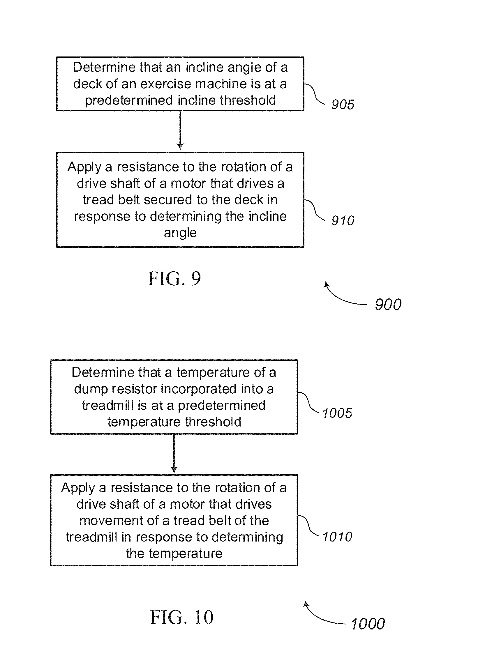
FIG. 9 shows a flowchart illustrating a method 900 for mitigating a runaway condition. The operations of method 900 may be implemented by a runaway mitigation system or its components as described herein. In some examples, a runaway mitigation system may execute a set of codes to control the functional elements of the device to perform the functions described below. Additionally or alternatively, the runaway mitigation system may perform aspects of the functions described below using special-purpose hardware. At block 905, an incline angle of the deck of an exercise machine is determined to be at a predetermined incline threshold. At block 910, a resistance is applied to the rotation of a drive shaft of a motor that drives a tread belt secured to the deck in response to determining the incline angle.
FIG. 10 shows a flowchart illustrating a method 1000 for mitigating a runaway condition. The operations of method 1000 may be implemented by a runaway mitigation system or its components as described herein. In some examples, a runaway mitigation system may execute a set of codes to control the functional elements of the device to perform the functions described below. Additionally or alternatively, the runaway mitigation system may perform aspects of the functions described below using special-purpose hardware. At block 1005, a temperature of a dump resistor incorporated into a treadmill is determined to be at a predetermined temperature threshold. At block 1010, a resistance is applied to the rotation of a drive shaft of a motor that drives movement of a tread belt of the treadmill in response to determining the temperature.
GENERAL DESCRIPTION
In general, the invention disclosed herein may provide users with an exercise machine that mitigates the effects of motor runaway. Not all commercial treadmills experience motor runaway due to a deck incline angle. However, in some cases where the treadmill deck inclines at a steeper angle than the industry's conventional treadmills do, the mechanical load on the treadmill motor can drop to a point where the motor that drives the tread belt experiences a runaway condition. In some situations, a runaway condition may result in the motor producing electricity. This electricity has to be directed somewhere, and in some cases, the runaway electricity is directed to a dump resistor where the excess electricity is converted to heat. This excess heat may raise the temperature of other components in the treadmill, which may reduce their useful life.
The load on the motor may be affected by multiple factors, such as the weight of the user, the angle of the deck, the friction between the tread belt and the deck's platform, the friction of the pulleys, the weight of the pulleys, the weight of the tread belt, other factors, or combinations thereof. When the angle of the treadmill's deck is substantially horizontal, the tread belt moves the user along the length of the deck. As the angle of the deck inclines, the user's weight pushes down on the tread belt as the user performs an exercise. For example, as the user applies a load on the tread belt when he or she pushes off of the tread belt during a walking or running exercise, the leg applies a downward force on the tread belt, which helps move the tread belt along in the same direction that the motor is driving the tread belt. The amount of force that contributes to the movement of the tread belt from the user depends, in part, on how hard the user applies the force and also the steepness of the incline angle. As a general rule, the steeper the incline angle, the more force that the user applies due to gravity pulling on the user. The weight of the user also affects the load to the tread belt as a heavier user may apply a greater load to the tread belt.
With the load applied by the user's weight moving the tread belt, at least in part, the electrical load on the motor can be reduced to keep the tread belt moving at the desired speed. However, in some cases, the weight of the user may cause the tread belt to move faster than the speed that the motor would otherwise run given the power load and the angle. In these cases, the motor may generate electricity as part of a runaway condition.
A runaway mitigation mechanism may apply an increased load on the motor, which can result in mitigating and/or eliminating the runaway condition. When mitigating the runaway condition, the amount of electricity produced by the motor may be reduced or entirely eliminated.
The treadmill may include a frame, a deck attached to the frame, and a tread belt incorporated into the deck. The frame may include a base portion that supports the deck on a support surface, such as a floor. A front pulley may be connected to a front portion of the deck, and a rear pulley may be connected to a rear portion of the deck. A tread belt surrounds the front pulley and the second pulley. A motor can drive either the front pulley or the rear pulley and cause the tread belt to move along a surface of the deck. The speed of the tread belt may be adjustable, based on the motor's output. In some cases, the user can select the tread belt's speed through an input incorporated into the treadmill.
In some examples, the treadmill includes an incline mechanism that is integrated into the base and controls an elevation of the front portion of the deck. The rear portion of the deck is connected to the base at a pivot connection. As the incline mechanism changes the elevation of the front portion of the deck, the rear portion of the deck remains connected to the base. Thus, the front portion of the deck inclines with respect to the base.
In some examples, the treadmill includes an upright structure that is connected to the base. In these examples, the upright structure includes a first post and a second post. The first post and the second post may include a console. The console may include an input mechanism that controls an operational parameter of the treadmill. In some cases, the console includes a cooling mechanism (e.g. fan), speakers, microphones, sensors, other features, or combinations thereof. In some cases, the console includes a display.
In some cases, the motor is located inside a housing. The drive motor may be disposed adjacent to a pulley that moves the tread belt in a rotational direction. The drive motor may be attached to the pulley with a drive shaft. A power supply may provide power to the motor to drive the rotation of the drive shaft. The power supply may be an external source, such as an alternating current system incorporated into a residence or other building, a generator, an alternative power source, another type power source, or combinations thereof. In some instances, the power supply may be internal to the housing and/or treadmill. In some cases, a flywheel is attached to and coaxial with the drive motor. The flywheel may rotate with the drive motor.
A lift motor may be connected to the deck and to the base frame of the treadmill. When activated, the lift motor may cause a rod to extend downward, which pushes against the front portion of the deck and the base frame, causing the front portion of the deck to raise. In other situations, when the lift motor is activated, the rod is retracted, which causes the front portion of the deck to lower. In these cases, the lift motor may be transversely oriented with respect to the fan assembly. While this example has been described in the context of having a lift motor as part of a system for inclining the deck, any appropriate mechanism may be used to incline the deck.
In those examples where the treadmill includes a console display, the console display may depict information about the user, the operational parameters of the treadmill, entertainment, other features, or combinations thereof. In those examples where the exercise machine is without a console, the exercise machine may be less expensive to manufacture, move, set up, transport, or combinations thereof.
The exercise machine may collect data about the user's physiological condition during the performance of an exercise. In some cases, sensors are incorporated into the exercise machine to gather specific types of physiological information about the user. These sensors may be located on the exercise machine where the user comes into contact with the exercise machine. For example, an electrical contact that is part of a heart rate monitoring system may be incorporated into hand rails, handles, or other types of supports incorporated into the exercise machine. The electrical contacts may detect electrical pulses transmitted through the user's body during the exercise, and these measurements may be used to determine the user's heart rate.
The existence of a runaway condition may be determined through any appropriate mechanism. For example, a current measuring device may determine if electricity is being generated by the motor. In those circumstances where the electricity is being generated by the motor, the processing resources may determine that a runaway condition exists. Any appropriate type of device to measure the amount of power produced by the motor may be used. In some examples, an ohmmeter, an ammeter, a multimeter, a capacitor, another type of measurement device, or combinations thereof may be used. In some cases, any electricity that is generated may be directed to a dump resistor where the electricity is converted to heat. A thermometer may be used to measure the dump resistor's temperature. In those cases where the thermometer records that the dump resistor's temperature is above a baseline temperature, the processing resources may determine that a runaway condition exists.
In other examples, a runaway condition may be presumed when the incline of the deck is above a certain threshold. While other factors may affect when a runaway condition exists, like the user's weight, the sensing electronics may be simplified by presuming that a runaway condition exists solely based on the deck's incline angle. In some cases when the runaway condition is presumed, the processing resources may determine that a runaway condition exists. In this type of example, the mechanical resistance on the motor may be increased regardless of whether an actual runaway condition exists or not. In other circumstances, the processing resources may initiate additional tests when a presumption of a runaway condition exists and initiate a runaway mitigation procedure in response to the findings of those tests.
In some cases, the user's weight is known or at least determinable to the processing resources. For example, the user may input his or her weight into an input mechanism incorporated into the console or through a remote device in communication with the treadmill. The weight of the user may determine which incline angle is classified as a runaway condition threshold angle. In other examples, the requested speed of the tread belt may affect and partially determine which incline angle is classified as a runaway condition threshold angle.
In other examples, a rotary sensor is associated with the drive shaft, a flywheel, a pulley, another rotary device, or combinations thereof that determine how fast these components are operating. The speed that the motor should be running based on the amount of electricity inputted into the motor may be compared with the actual speed of the motor to determine whether a runaway condition exists.
In another example, the motor is determined to be in a runaway condition if the angle of the incline deck is above a predetermined threshold angle. In some cases, this predetermined threshold angle is adjustable based on the weight of the user, the inputted speed for the tread belt to move, other factors, or combinations thereof.
The runaway mitigation system may include a combination of hardware and programmed instructions for executing the functions of the runaway mitigation system. In this example, the runaway mitigation system includes processing resources that are in communication with memory resources. Processing resources include at least one processor and other resources used to process the programmed instructions. The memory resources represent generally any memory capable of storing data such as programmed instructions or data structures used by the runaway mitigation system. The programmed instructions and data structures shown stored in the memory resources include an incline determiner, a belt speed determiner, a resistor thermometer, and a resistance determiner.
Input/output (I/O) resources are in communication with the processing resources. The I/O resources may include any appropriate type of mechanism for communicating with remote devices. For example, the I/O resources may include a transmitter, a wireless transmitter, a receiver, a transceiver, a port for receiving an external memory, a network interface, another I/O resource, or combinations thereof.
The I/O resources may be in communication with any appropriate device. In the illustrated example, the I/O resources are in communication with an incline sensor, an odometer, a thermometer, a motor, another remote device, a runaway mitigation mechanism, or combinations thereof. These remote devices may be located on the treadmill, may be independent of the treadmill, may be in communication with the I/O resources over a network, may be part of a wearable device, or combinations thereof. Such protocols may include standard wireless protocols, protocols used by Bluetooth.RTM. technologies, Wi-Fi protocols, Z-wave protocols, Zigbee protocols, other types of wireless protocols, or combinations thereof.
The processing resources may include one or more processors. The processing resources may include an intelligent hardware device, (e.g., a general-purpose processor, a digital signal processor (DSP), a central processing unit (CPU), a microcontroller, an application specific integrated circuit (ASIC), a field-programmable gate array (FPGA), a programmable logic device, a discrete gate or transistor logic component, a discrete hardware component, or any combination thereof). In some cases, the processing resources may be configured to operate a memory array using a memory controller. In other cases, a memory controller may be integrated into the processor. The processing resources may be configured to execute computer-readable instructions stored in a memory to perform various functions (e.g., function or tasks supporting overlaying exercise information on a remote display).
An I/O controller may manage input and output signals for the runaway mitigation system and/or the exercise machine. Input/output control components may also manage peripherals not integrated into these devices. In some cases, the input/output control component may represent a physical connection or port to an external peripheral. In some cases, I/O controller may utilize an operating system such as iOS.RTM., ANDROID.RTM., MS-DOS.RTM., MS-WINDOWS.RTM., OS/2.RTM., UNIX.RTM., LINUX.RTM., or another known operating system.
Memory resources may include random access memory (RAM) and read only memory (ROM). The memory may store computer-readable, computer-executable software including instructions that, when executed, cause the processor to perform various functions described herein. In some cases, the memory resources can contain, among other things, a Basic Input-Output system (BIOS) which may control basic hardware and/or software operation such as the interaction with peripheral components or devices.
The incline determiner represents programmed instructions that, when executed, cause the processor to determine the incline of the treadmill deck. In some cases, the incline determiner requests the angle from a distance sensor, from a level sensor, from a gravity sensor, from an accelerometer, from another type of sensor, or combinations thereof. In response, the sensor may send raw data to the incline determiner where the raw data is interpreted to determine the incline angle. In other examples, the incline determiner receives data that is at least partially processed. In other examples, the incline mechanism of the treadmill is in communication with the incline determiner. The incline mechanism may know the incline angle at which it has set the deck and may continuously send, periodically send, or send on demand information about the angle to the incline determiner.
The belt speed determiner represents programmed instructions that, when executed, cause the processor to determine the speed that the tread belt is moving. In some cases, the speed determiner requests the speed from an odometer, optical sensor, an accelerometer, another type of sensor, or combinations thereof. In response, the sensor may send raw data to the speed determiner where the raw data is interpreted to determine the tread belt speed. In other examples, the belt speed determiner receives data that is at least partially processed.
The resistor thermometer represents programmed instructions that, when executed, cause the processor to determine a temperature of at least one component of the treadmill that is indicative of a runaway condition. In one example, the resistor thermometer may measure the temperature of a dump resistor that is in electrical communication with the motor. In those conditions where the motor is in a runaway condition, the motor may be generating electricity and the generated electricity may be directed to the dump resistor to convert this electricity into heat. Under those circumstances where the dump resistor's temperature is above a predetermined threshold, the processor may determine that a runaway condition exists.
The resistance determiner represents programmed instructions that, when executed, cause the processor to determine a resistance load on the motor. The resistance determiner may take inputs from the incline determiner, the belt speed determiner, the resistor thermometer, a user weight input, an inputted tread belt speed, an actual tread belt speed, other information, or combinations thereof.
In some cases, the resistance determiner measures the speed inputted into the console by the user to operate the tread belt (inputted speed). The inputted speed may be compared to the actual speed determined by the belt speed determiner or through another mechanism. If the actual speed and the inputted speed do not match, the resistance determiner may conclude that the resistance on the motor is too low to prevent a runaway condition or the processor may determine that a runaway condition exists.
In some examples, the resistance determiner may determine that an insufficient load exists on the motor to prevent a runaway condition when the temperature of the resistor is above a predetermined temperature threshold. In other examples, the resistance determiner may determine that an insufficient amount of resistance exists on the motor when the incline deck is orientated at an angle above a predetermined threshold angle.
While the above examples have been described with reference to specific mechanisms for determining that a runaway condition exists, any appropriate mechanism may be used to determine whether a runaway condition exists. In some examples, sensors incorporated into the treadmill are used to determine the existence of a runway condition. In other examples, sensors or information from a remote device may at least contribute to determining whether a runaway condition exists.
The treadmill may include a runaway mitigation mechanism. In some examples, the runaway mitigation mechanism is an active mechanism that operates in response to a determination that a runaway condition exists or is at least approaching a potential runaway condition. The active runaway mitigation mechanism may respond by increasing the load on the motor. In other examples, the runaway mitigation mechanism is a passive mechanism that automatically applies a greater resistance to the motor.
The active runaway mitigation mechanism may prevent a runaway condition from starting or may reduce, or even eliminate, the runaway condition. The active runaway condition mitigation mechanism may include a braking mechanism, a compressive braking mechanism, a hydraulic mechanism, a pneumatic mechanism, another type of mechanism, or combinations thereof that apply mechanical resistance to a rotation of the motor's drive shaft.
In some cases, a drive shaft extends beyond a motor casing, and a rotary disc is rigidly attached to the drive shaft. In some of these examples, a compression brake can be positioned adjacent to the rotary disc. The compression brake may include a first pad adjacent a first side of the rotary disc, and a second pad adjacent a second side of the rotary disc. When activated, the first pad and the second pad move towards the rotary disc simultaneously and apply a compressive load to the rotary disc which resists rotational movement of the rotary disc. Under certain conditions, the compression brake may apply a compressive load that is sufficient to prevent the rotary disc, and therefore the drive shaft, from rotating at all. Under other conditions, the compression brake may apply a compressive load that merely increases the resistance to the rotational movement of the rotary disc, but is not sufficient to stop the drive shaft from rotating. When a runaway condition is sensed, the compression brake may be activated to increase the mechanical resistance to the motor to at least mitigate the runaway condition.
In another example, the rotary disc may include at least some magnetically conductive material. A magnetic unit may be positioned adjacent to a rim of the rotary disc. The magnetic unit may apply a magnetic force on the rotary disc that resists movement of the rotary disc and therefore movement of the drive shaft.
The magnetic unit may be positionable with a linear actuator. The linear actuator may include an actuator motor and a screw rod. In this example, as the motor operates in a first direction, the screw rod moves the magnetic unit in a direction towards the rotary disc. In the same example, as the motor operates in a second direction, the screw rod moves the magnetic unit in another direction away from the rotary disc. As the magnetic unit approaches the rotary disc, the magnetic load applied to the rotary disc may increase so that more resistance is applied to the rotary disc's movement and mechanical resistance on the motor increases. Similarly, as the magnetic unit moves away from the rotary disc, the magnetic load on the rotary disc may decrease, which lowers mechanical resistance on the motor. In alternative embodiments, the magnetic unit is an electromagnet that produces a magnetic field that is proportional to the power supplied to the magnetic unit. In this example, the magnetic strength applied to the rotary disc is adjustable by varying the power to the magnetic unit. In yet additional embodiments, a viscous fluid may be selectively introduced into a container housing the drive shaft when a runaway condition is present.
In those examples where the runaway mitigation mechanism is passive, the resistance may be applied automatically without a command instruction to the motor under those circumstances when a runaway condition is more likely to occur. For example, the increased resistance on the motor may be automatically applied when the treadmill deck is inclined above a predetermined threshold angle.
In one example of a passive runaway mitigation mechanism, the mechanism includes a container and a portion of the drive shaft is partially disposed within the container. The container includes a fluid, such as an oil-based fluid. In some cases, the container moves with the deck. So, when the deck is in a level orientation, the container is held at a corresponding orientation. On the other hand, when the deck is inclined at an angle, the container is held in a tilting orientation.
In the level orientation, the fluid resides under the drive shaft without making contact with the drive shaft. In the tilted orientation, the fluid may pool in the proximity of the drive shaft so that the fluid is in contact with the drive shaft. In the illustrated example, the drive shaft is immersed in the fluid so that an entire circumference of the drive shaft is in contact with the fluid. In some examples, the contact with the drive shaft resists rotation of the drive shaft. In some cases, the viscosity of the fluid resists the rotation of the shaft. In some cases, the shaft has a generally symmetric shape, and the surface friction of the cylindrical shape and the fluid increases the resistance to the rotation of the drive shaft.
In other examples, the drive shaft may include features that increase the amount of resistance applied from at least partial immersion into the fluid. One feature that may increase the resistance includes at least one vane attached to the drive shaft. The vane may push against the fluid as the drive shaft rotates thereby increasing the resistance to the rotation of the drive shaft. While this example has been depicted in the context of using a vane for increasing the resistance to the drive shaft's rotation, any appropriate type of feature that can increase the resistance via engagement with the fluid may be incorporated into the drive shaft.
In another example, a magnet may come into closer proximity with the drive shaft as the deck is inclined. In this example, the closer that the magnet is to the drive shaft, the greater influence the magnet's flux has on the drive shaft resulting in a greater resistance to the rotation of the drive shaft.
It should be noted that the methods described above describe possible implementations, and that the operations and the steps may be rearranged or otherwise modified and that other implementations are possible. For example, the present systems and techniques may be applied to other components of the treadmill including, but in no way limited to, the pulleys. Furthermore, aspects from two or more of the methods may be combined.
Information and signals described herein may be represented using any of a variety of different technologies and techniques. For example, data, instructions, commands, information, signals, bits, symbols, and chips that may be referenced throughout the above description may be represented by voltages, currents, electromagnetic waves, magnetic fields or particles, optical fields or particles, or any combination thereof.
The various illustrative blocks and modules described in connection with the disclosure herein may be implemented or performed with a general-purpose processor, a DSP, an ASIC, an FPGA or other programmable logic device, discrete gate or transistor logic, discrete hardware components, or any combination thereof designed to perform the functions described herein. A general-purpose processor may be a microprocessor, but in the alternative, the processor may be any conventional processor, controller, microcontroller, or state machine. A processor may also be implemented as a combination of computing devices (e.g., a combination of a digital signal processor (DSP) and a microprocessor, multiple microprocessors, one or more microprocessors in conjunction with a DSP core, or any other such configuration).
The functions described herein may be implemented in hardware, software executed by a processor, firmware, or any combination thereof. If implemented in software executed by a processor, the functions may be stored on or transmitted over as one or more instructions or code on a computer-readable medium. Other examples and implementations are within the scope of the disclosure and appended claims. For example, due to the nature of software, functions described above can be implemented using software executed by a processor, hardware, firmware, hardwiring, or combinations of any of these. Features implementing functions may also be physically located at various positions, including being distributed so that portions of functions are implemented at different physical locations.
Computer-readable media includes both non-transitory computer storage media and communication media including any medium that facilitates transfer of a computer program from one place to another. A non-transitory storage medium may be any available medium that can be accessed by a general purpose or special purpose computer. By way of example, and not limitation, non-transitory computer-readable media can include RAM, ROM, electrically erasable programmable read only memory (EEPROM), compact disk (CD) ROM or other optical disk storage, magnetic disk storage or other magnetic storage devices, or any other non-transitory medium that can be used to carry or store desired program code means in the form of instructions or data structures and that can be accessed by a general-purpose or special-purpose computer, or a general-purpose or special-purpose processor. Also, any connection is properly termed a computer-readable medium. In some cases, the software is transmitted from a website, server, or other remote source using a coaxial cable, fiber optic cable, twisted pair, digital subscriber line (DSL), or wireless technologies such as infrared, radio, and microwave, then the coaxial cable, fiber optic cable, twisted pair, digital subscriber line (DSL), or wireless technologies such as infrared, radio, and microwave are included in the definition of medium. A portable medium, as used herein, include CD, laser disc, optical disc, digital versatile disc (DVD), floppy disk and Blu-ray disc where disks usually reproduce data magnetically, while discs reproduce data optically with lasers. Combinations of the above are also included within the scope of computer-readable media.
The description herein is provided to enable a person skilled in the art to make or use the disclosure. Various modifications to the disclosure will be readily apparent to those skilled in the art, and the generic principles defined herein may be applied to other variations without departing from the scope of the disclosure. Thus, the disclosure is not limited to the examples described herein, but is to be accorded the broadest scope consistent with the principles and novel features disclosed herein.
* * * * *
D00000
D00001
D00002
D00003
D00004
D00005
D00006
D00007
XML
uspto.report is an independent third-party trademark research tool that is not affiliated, endorsed, or sponsored by the United States Patent and Trademark Office (USPTO) or any other governmental organization. The information provided by uspto.report is based on publicly available data at the time of writing and is intended for informational purposes only.
While we strive to provide accurate and up-to-date information, we do not guarantee the accuracy, completeness, reliability, or suitability of the information displayed on this site. The use of this site is at your own risk. Any reliance you place on such information is therefore strictly at your own risk.
All official trademark data, including owner information, should be verified by visiting the official USPTO website at www.uspto.gov. This site is not intended to replace professional legal advice and should not be used as a substitute for consulting with a legal professional who is knowledgeable about trademark law.