Elliptical Exercise Machine
Dalebout; William T. ; et al.
U.S. patent application number 16/351156 was filed with the patent office on 2019-09-19 for elliptical exercise machine. The applicant listed for this patent is ICON Health & Fitness, Inc.. Invention is credited to William T. Dalebout, Gaylen Ercanbrack.
| Application Number | 20190282852 16/351156 |
| Document ID | / |
| Family ID | 67904973 |
| Filed Date | 2019-09-19 |


View All Diagrams
| United States Patent Application | 20190282852 |
| Kind Code | A1 |
| Dalebout; William T. ; et al. | September 19, 2019 |
Elliptical Exercise Machine
Abstract
An elliptical exercise machine may include a base, one or more upright stanchions coupled to the base and extending upward from the base and supporting first and second cranks. The first crank may support a first crank arm. The first crank arm may support a first pedal leg hanging downward from the first crank arm. The first pedal leg may support a right pedal. The right pedal may be configured to swing forward and rearward and to raise upward and lower downward. The second crank may support a second crank arm. The second crank arm may support a second pedal leg hanging downward from the second crank arm. The second pedal leg may support a left pedal. The left pedal may be configured to swing forward and rearward and to raise upward and lower downward.
| Inventors: | Dalebout; William T.; (North Logan, UT) ; Ercanbrack; Gaylen; (Logan, UT) | ||||||||||
| Applicant: |
|
||||||||||
|---|---|---|---|---|---|---|---|---|---|---|---|
| Family ID: | 67904973 | ||||||||||
| Appl. No.: | 16/351156 | ||||||||||
| Filed: | March 12, 2019 |
Related U.S. Patent Documents
| Application Number | Filing Date | Patent Number | ||
|---|---|---|---|---|
| 62644133 | Mar 16, 2018 | |||
| Current U.S. Class: | 1/1 |
| Current CPC Class: | A63B 2220/22 20130101; A63B 2220/17 20130101; A63B 21/225 20130101; A63B 2220/80 20130101; A63B 2022/0676 20130101; A63B 21/00192 20130101; A63B 24/0084 20130101; A63B 23/03575 20130101; A63B 21/154 20130101; A63B 2209/08 20130101; A63B 2220/20 20130101; A63B 2230/40 20130101; A63B 71/0622 20130101; A63B 22/0664 20130101; A63B 22/001 20130101; A63B 2210/00 20130101; A63B 2230/06 20130101; A63B 2022/0682 20130101; A63B 2230/75 20130101 |
| International Class: | A63B 22/06 20060101 A63B022/06; A63B 21/22 20060101 A63B021/22; A63B 21/00 20060101 A63B021/00; A63B 22/00 20060101 A63B022/00; A63B 23/035 20060101 A63B023/035 |
Claims
1. An elliptical exercise machine comprising: a base; one or more upright stanchions coupled to the base and extending upward from the base; a first crank supported by the one or more upright stanchions, the first crank supporting a first crank arm that is offset from the center of the first crank, the first crank arm supporting a first pedal leg hanging downward from the first crank arm, the first pedal leg supporting a right pedal, the right pedal configured to swing forward and rearward by a user's right foot striding forward and rearward with a length of each swing determined by a length of a stride of the user's right foot, the right pedal configured to raise upward and lower downward as the first crank arm moves upward and downward during rotation of the first crank; and a second crank supported by the one or more upright stanchions, the second crank supporting a second crank arm that is offset from the center of the second crank, the second crank arm supporting a second pedal leg hanging downward from the second crank arm, the second pedal leg supporting a left pedal, the left pedal configured to swing forward and rearward by a user's left foot striding forward and rearward with a length of each swing determined by a length of a stride of the user's left foot, the left pedal configured to raise upward and lower downward as the second crank arm moves upward and downward during rotation of the second crank.
2. The elliptical exercise machine of claim 1, further comprising: a flywheel coupled to the first crank and/or the second crank, the flywheel configured to provide resistance to rotation of the first crank and/or the second crank.
3. The elliptical exercise machine of claim 2, further comprising: a magnetic brake configured to provide variable resistance to the rotation of the flywheel.
4. The elliptical exercise machine of claim 2, further comprising: a crank pulley configured to rotate in phase with the first crank or with the second crank; a double-reduction pulley; a flywheel belt coupling the flywheel to the double-reduction pulley; and an intermediate belt coupling the double-reduction pulley to the crank pulley.
5. The elliptical exercise machine of claim 1, further comprising: a timing shaft and belts and pulleys coupling the first crank to the second crank to cause the first crank arm to rotate about 180 degrees out of phase from the second crank arm.
6. The elliptical exercise machine of claim 5, wherein: the timing shaft is coupled to the one or more upright stanchions.
7. The elliptical exercise machine of claim 5, wherein belts and pulleys include: a first crank pulley configured to rotate in phase with the first crank; a first timing shaft pulley configured to rotate in phase with the timing shaft; a first belt coupling the first crank pulley to the first timing shaft pulley; a second crank pulley configured to rotate in phase with the second crank; a second timing shaft pulley configured to rotate in phase with the timing shaft; and a second belt coupling the second crank pulley to the second timing shaft pulley.
8. The elliptical exercise machine of claim 1, further comprising: a timing cable and pulleys coupling the first crank to the second crank to cause the first crank arm to rotate about 180 degrees out of phase from the second crank arm.
9. The elliptical exercise machine of claim 8, wherein the pulleys include: a first crank pulley configured to rotate in phase with the first crank; upper and lower first timing pulleys; a second crank pulley configured to rotate in phase with the second crank; and upper and lower second timing pulleys.
10. The elliptical exercise machine of claim 9, wherein the timing cable is configured in a loop and is configured to couple the first crank pulley to the upper and lower first timing pulleys, and to couple the upper and lower first timing pulleys to the upper and lower second timing pulleys, and to couple the upper and lower second timing pulleys to the second crank pulley.
11. The elliptical exercise machine of claim 1, further comprising: a first swing handle, the first swing handle coupled to a first swing arm, the first swing arm coupled to the first pedal leg; and a second swing handle, the second swing handle coupled to a second swing arm, the second swing arm coupled to the second pedal leg.
12. The elliptical exercise machine of claim 11, wherein: the first pedal leg is supported by the first crank arm via a coupling to a first roller arm, the first roller arm configured to roll atop a first roller that is coupled to the first crank arm; and the second pedal leg is supported by the second crank arm via a coupling to a second roller arm, the second roller arm configured to roll atop a second roller that is coupled to the second crank arm.
13. The elliptical exercise machine of claim 12, further comprising: a second first pedal leg supported by the first swing arm and hanging downward from the first swing arm, the second first pedal leg further supporting the right pedal; and a second pedal leg supported by the second swing arm and hanging downward from the second swing arm, the second pedal leg further supporting the left pedal.
14. The elliptical exercise machine of claim 13, wherein: a surface of the first roller arm that is configured to roll atop the first roller is curved; and a surface of the second roller arm that is configured to roll atop the second roller is curved.
15. The elliptical exercise machine of claim 14, wherein: the curved surface of the first roller arm is a concave surface; and the curved surface of the second roller arm is a concave surface.
16. The elliptical exercise machine of claim 14, wherein: the curved surface of the first roller arm is a convex surface; and the curved surface of the second roller arm is a convex surface.
17. The elliptical exercise machine of claim 1, wherein: at least a portion of the right pedal is configured to swing rearward further than a rearmost portion of the base; and at least a portion of the left pedal is configured to swing rearward further than a rearmost portion of the base.
Description
CROSS-REFERENCE TO RELATED APPLICATIONS
[0001] This application claims the benefit of and priority to provisional patent application No. 62/644,133 entitled "ELLIPTICAL EXERCISE MACHINE" filed Mar. 16, 2018, which application is herein incorporated by reference in its entirety for all that it discloses.
BACKGROUND
[0002] Elliptical exercise machines are generally configured to allow users to simulate striding motions along an elliptical path as a way to exercise a variety of muscles through a wide range of motion. Since their introduction, elliptical exercise machines have become very popular with users due to the generally low-impact exercise they enable as compared to other striding exercises such as walking, jogging, or running.
[0003] Unfortunately, however, conventional elliptical exercise machines generally have fixed elliptical paths which can be uncomfortable for users. Also, conventional elliptical exercise machines generally have relatively long front-to-back footprints that take up relatively large amounts of floor space, which can make them difficult to fit onto the floor space in a gym or a home.
[0004] The subject matter claimed herein is not limited to embodiments that solve any disadvantages or that operate only in environments such as those described above. Rather, this background is only provided to illustrate one example technology area where some embodiments described herein may be practiced.
SUMMARY
[0005] In one aspect of the disclosure, an elliptical exercise machine may include a base, one or more upright stanchions coupled to the base and extending upward from the base and supporting first and second cranks. The first crank may support a first crank arm that is offset from the center of the first crank. The first crank arm may support a first pedal leg hanging downward from the first crank arm. The first pedal leg may support a right pedal. The right pedal may be configured to swing forward and rearward by a user's right foot striding forward and rearward with a length of each swing determined by a length of a stride of the user's right foot. The right pedal may be configured to raise upward and lower downward as the first crank arm moves upward and downward during rotation of the first crank. The second crank may support a second crank arm that is offset from the center of the second crank. The second crank arm may support a second pedal leg hanging downward from the second crank arm. The second pedal leg may support a left pedal. The left pedal may be configured to swing forward and rearward by the user's left foot striding forward and rearward with a length of each swing determined by a length of a stride of the user's left foot. The left pedal may be configured to raise upward and lower downward as the second crank arm moves upward and downward during rotation of the second crank.
[0006] Another aspect of the disclosure may include any combination of the above-mentioned features and may further include the elliptical exercise machine further including a flywheel coupled to the first crank and/or the second crank, with the flywheel configured to provide resistance to rotation of the first crank and/or the second crank.
[0007] Another aspect of the disclosure may include any combination of the above-mentioned features and may further include the elliptical exercise machine further including a magnetic brake configured to provide variable resistance to the rotation of the flywheel.
[0008] Another aspect of the disclosure may include any combination of the above-mentioned features and may further include the elliptical exercise machine further including a crank pulley configured to rotate in phase with the first crank or with the second crank, a double-reduction pulley, a flywheel belt coupling the flywheel to the double-reduction pulley, and an intermediate belt coupling the double-reduction pulley to the crank pulley.
[0009] Another aspect of the disclosure may include any combination of the above-mentioned features and may further include the elliptical exercise machine further including a timing shaft and belts and pulleys coupling the first crank to the second crank to cause the first crank arm to rotate about 180 degrees out of phase from the second crank arm.
[0010] Another aspect of the disclosure may include any combination of the above-mentioned features and may further include the timing shaft being coupled to the one or more upright stanchions.
[0011] Another aspect of the disclosure may include any combination of the above-mentioned features and may further include the belts and pulleys including a first crank pulley configured to rotate in phase with the first crank, a first timing shaft pulley configured to rotate in phase with the timing shaft, a first belt coupling the first crank pulley to the first timing shaft pulley, a second crank pulley configured to rotate in phase with the second crank, a second timing shaft pulley configured to rotate in phase with the timing shaft, and a second belt coupling the second crank pulley to the second timing shaft pulley.
[0012] Another aspect of the disclosure may include any combination of the above-mentioned features and may further include the elliptical exercise machine further including a timing cable and pulleys coupling the first crank to the second crank to cause the first crank arm to rotate about 180 degrees out of phase from the second crank arm.
[0013] Another aspect of the disclosure may include any combination of the above-mentioned features and may further include the pulleys including a first crank pulley configured to rotate in phase with the first crank, upper and lower first timing pulleys, a second crank pulley configured to rotate in phase with the second crank, and upper and lower second timing pulleys.
[0014] Another aspect of the disclosure may include any combination of the above-mentioned features and may further include the timing cable being configured in a loop and being configured to couple the first crank pulley to the upper and lower first timing pulleys, and to couple the upper and lower first timing pulleys to the upper and lower second timing pulleys, and to couple the upper and lower second timing pulleys to the second crank pulley. Another aspect of the disclosure may include any combination of the above-mentioned features and may further include the elliptical exercise machine further including a first swing handle and a second swing handle. The first swing handle may be coupled to a first swing arm. The first swing arm may be coupled to the first pedal leg. The second swing handle may be coupled to a second swing arm. The second swing arm may be coupled to the second pedal leg.
[0015] Another aspect of the disclosure may include any combination of the above-mentioned features and may further include the first pedal leg being supported by the first crank arm via a coupling to a first roller arm, with the first roller arm configured to roll atop a first roller that is coupled to the first crank arm, and the second pedal leg being supported by the second crank arm via a coupling to a second roller arm, with the second roller arm configured to roll atop a second roller that is coupled to the second crank arm.
[0016] Another aspect of the disclosure may include any combination of the above-mentioned features and may further include the elliptical exercise machine further including a second first pedal leg supported by the first swing arm and hanging downward from the first swing arm, with the second first pedal leg further supporting the right pedal, and a second pedal leg supported by the second swing arm and hanging downward from the second swing arm, with the second pedal leg further supporting the left pedal.
[0017] Another aspect of the disclosure may include any combination of the above-mentioned features and may further include a surface of the first roller arm that is configured to roll atop the first roller being curved and a surface of the second roller arm that is configured to roll atop the second roller being curved, with each curved surface being a concave surface or a convex surface.
[0018] Another aspect of the disclosure may include any combination of the above-mentioned features and may further include at least a portion of the right pedal being configured to swing rearward further than a rearmost portion of the base, and at least a portion of the left pedal being configured to swing rearward further than a rearmost portion of the base.
[0019] It is to be understood that both the foregoing summary and the following detailed description are explanatory and are not restrictive of the invention as claimed.
BRIEF DESCRIPTION OF THE DRAWINGS
[0020] Embodiments will be described and explained with additional specificity and detail through the use of the accompanying drawings in which:
[0021] FIGS. 1A-1G are rear-right, rear, right, front, left, top, and bottom perspective views, respectively, of a first example elliptical exercise machine;
[0022] FIGS. 2A-2G are right-rear, rear, right, front, left, top, and bottom perspective views, respectively, of a second example elliptical exercise machine;
[0023] FIGS. 3A-3E are left views of a combination of the first and second example elliptical exercise machines, illustrating an example elliptical path of the first and second example elliptical exercise machines;
[0024] FIGS. 4A-4G are front-left, rear, right, front, left, top, and bottom perspective views, respectively, of a third example elliptical exercise machine;
[0025] FIGS. 5A-5E are left views of the third example elliptical exercise machine, illustrating an example elliptical path of the third example elliptical exercise machine;
[0026] FIGS. 6A-6G are front-left, rear, right, front, left, top, and bottom perspective views, respectively, of a fourth example elliptical exercise machine;
[0027] FIGS. 7A-7E are left views of the fourth example elliptical exercise machine, illustrating an example elliptical path of the fourth example elliptical exercise machine;
[0028] FIGS. 8A-8G are front-left, rear, right, front, left, top, and bottom perspective views, respectively, of a fifth example elliptical exercise machine; and
[0029] FIGS. 9A-9E are left views of the fifth example elliptical exercise machine, illustrating an example elliptical path of the fifth example elliptical exercise machine.
[0030] Throughout the drawings, identical reference numbers designate similar, but not necessarily identical, elements.
DETAILED DESCRIPTION
[0031] While conventional elliptical exercise machines have become very popular with users, conventional elliptical exercise machines generally have shortcomings of an uncomfortable fixed elliptical path and a relatively long front-to-back footprint that takes up a relatively large amount of floor space in a gym or in a home.
[0032] Some embodiments disclosed herein are elliptical exercise machines that overcome the shortcomings of conventional exercise machines. For example, the example elliptical exercise machines disclosed herein may allow for an elliptical path that has a dynamically variable stride length which allows the user to stride with a stride length that is comfortable to the user. Also, the example elliptical exercise machines disclosed herein have a shorter front-to-back footprint than conventional elliptical exercise machines, which may enable the example elliptical exercise machines disclosed herein to take up relatively small amounts of floor space, which can make them easier to fit onto the floor space in a gym or in a home. In this manner, the example elliptical exercise machines disclosed herein overcome the shortcomings of conventional elliptical exercise machines, thus enabling a more comfortable elliptical exercise for users while using less floor space in a gym or in a home.
[0033] Turning now to the drawings, FIGS. 1A-1G are rear-right, rear, right, front, left, top, and bottom perspective views, respectively, of a first example elliptical exercise machine 100.
[0034] The machine 100 may include a base 102, a right upright stanchion 104 coupled to the base 102 and extending upward from the base 102, and a left upright stanchion 154 coupled to the base 102 and extending upward from the base 102.
[0035] The right upright stanchion 104 may support a right crank 106. The right crank 106 may support a right crank arm 108 that is offset from the center of the right crank 106. The right crank arm 108 may support a right pedal leg 110 hanging downward from the right crank arm 108. The right pedal leg 110 may support a right pedal 112. Similarly, the left upright stanchion 154 may support a left crank 156. The left crank 156 may support a left crank arm 158 that is offset from the center of the left crank 156. The left crank arm 158 may support a left pedal leg 160 hanging downward from the left crank arm 158. The left pedal leg 160 may support a left pedal 162.
[0036] The machine 100 may further include a flywheel 164 coupled to the left crank 156. The flywheel 164 may be configured to provide resistance to rotation of the left crank 156. The machine 100 may further include a crank pulley 166 (note, in the machine 100, an outer surface of the left crank 156 functions as the crank pulley 166) configured to rotate in phase with the left crank 156, a double-reduction pulley 168, a flywheel belt 170 coupling the flywheel 164 to the double-reduction pulley 168, and an intermediate belt 172 coupling the double-reduction pulley 168 to the crank pulley 166.
[0037] The machine 100 may further include a timing shaft 174 and belts and pulleys coupling the right crank to the left crank to cause the right crank arm 108 to rotate about 180 degrees out of phase from the left crank arm 158. These belts and pulleys may include a right crank pulley 126 configured to rotate in phase with the right crank 106, a right timing shaft pulley 128 configured to rotate in phase with the timing shaft 174, a right belt 130 coupling the right crank pulley 126 to the right timing shaft pulley 128, a left crank pulley 176 configured to rotate in phase with the left crank 156, a left timing shaft pulley 178 configured to rotate in phase with the timing shaft 174, and a left belt 180 coupling the left crank pulley 176 to the left timing shaft pulley 178. The timing shaft 174 may be coupled to the right upright stanchion 104 and the left upright stanchion 154, such as being coupled to generally horizontal and forward portions of the right upright stanchion 104 and the left upright stanchion 154.
[0038] The machine 100 may further include a right swing handle 132 and a left swing handle 182 configured to be gripped by a user's right and left hands, respectively, during an exercise session. The right swing handle 132 may be coupled to a right swing arm 134. Although not shown in the figures, it is understood that the right swing arm 134 may be coupled to the right pedal leg 110, using a bolt and a nut for example. Although not shown in the figures, it is understood that the left swing handle 182 may be coupled to a left swing arm 184. The left swing arm 184 may be coupled to the left pedal leg 160, using a bolt and a nut for example. The right swing handle 132 and the left swing handle 182 may enable a user to coordinate movement of the user's arms and legs during an exercise session.
[0039] FIGS. 2A-2G are right-rear, rear, right, front, left, top, and bottom perspective views, respectively, of a second example elliptical exercise machine 200. The machine 200 is similar to the machine 100, and therefore the discussion of the machine 200 will generally be limited to aspects of the machine 200 that differ from the machine 100.
[0040] In place of the timing shaft 174, the right timing shaft pulley 128, the right belt 130, the left timing shaft pulley 178, and the left belt 180 of the machine 100, the machine 200 may include a timing cable 136 and pulleys coupling the right crank 106 to the left crank 156 to cause the right crank arm 108 to rotate about 180 degrees out of phase from the left crank arm 158. These pulleys may include the right crank pulley 126 that is configured to rotate in phase with the right crank 106, upper and lower right timing pulleys 138 and 140, the left crank pulley 176 configured to rotate in phase with the left crank 156, and upper and lower left timing pulleys 188 and 190. The timing cable 136 may be configured in a loop and may be configured to couple the right crank pulley 126 to the upper and lower right timing pulleys 138 and 140, and to couple the upper and lower right timing pulleys 138 and 140 to the upper and lower left timing pulleys 188 and 190, and to couple the upper and lower left timing pulleys 188 and 190 to the left crank pulley 176. The machine 200 may further include a right cable guide 142 and a left cable guide 192 to maintain the timing cable 136 in the proper position with respect to the pulleys through which the timing cable 136 is routed.
[0041] FIGS. 3A-3E are left views of a combination of the first and second example elliptical exercise machines 100 and 200, illustrating an example elliptical path 300 of the first and second example elliptical exercise machines 100 and 200.
[0042] During operation of the machines 100 and 200, the right pedal 112 may be configured to swing forward and rearward along the elliptical path 300 by a user's right foot striding forward and rearward with a length 302 of each swing determined by a length of a stride of the user's right foot. The right pedal 112 may be configured to raise upward and lower downward along the elliptical path 300 as the right crank arm 108 (see e.g., FIGS. 1A and 2A) moves upward and downward during rotation of the right crank 106 (see e.g., FIGS. 1A and 2A). Similarly, the left pedal 162 may be configured to swing forward and rearward along the elliptical path 300 by a user's left foot striding forward and rearward with a length 302 of each swing determined by a length of a stride of the user's left foot. The left pedal 162 may be configured to raise upward and lower downward along the elliptical path 300 as the left crank arm 158 (see e.g., FIGS. 1A and 2A) moves upward and downward during rotation of the left crank 156.
[0043] The machines 100 and 200 may allow the elliptical path 300 to have a dynamically variable stride length 302 which allows the user to stride with a stride length that is comfortable to the user. Also, machines 100 and 200 may have a shorter front-to-back footprint than conventional elliptical exercise machines. This relatively shorter front-to-back footprint may result in at least a portion of the right pedal 112 being configured to swing rearward further than a rearmost portion of the base 102 (see, e.g., FIG. 3D) and at least a portion of the left pedal 162 being configured to swing rearward further than a rearmost portion of the base 102 (see, e.g., FIG. 3B).
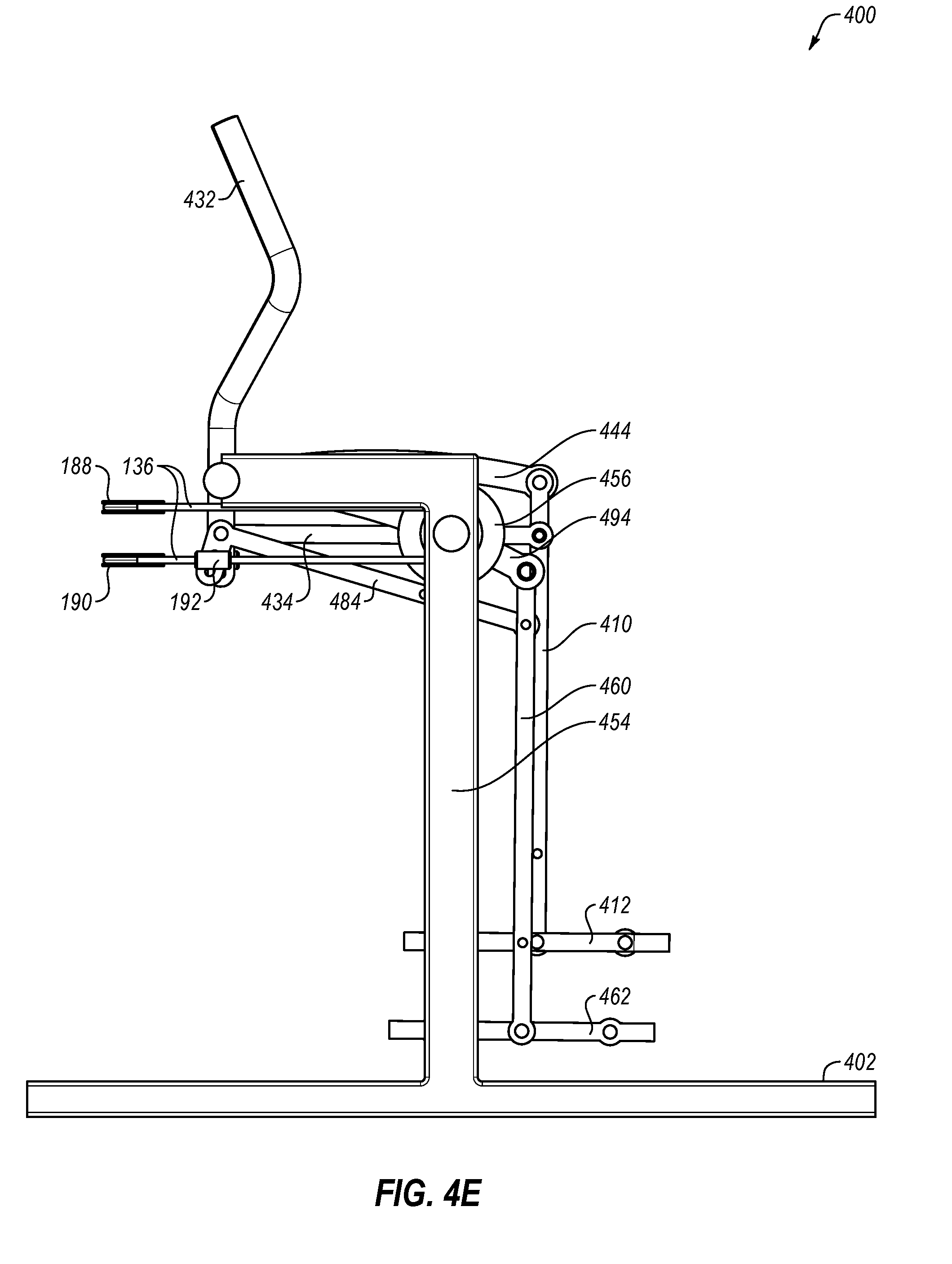
[0044] FIGS. 4A-4G are front-left, rear, right, front, left, top, and bottom perspective views, respectively, of a third example elliptical exercise machine 400.
[0045] The machine 400 may include a base 402, a right upright stanchion 404 coupled to the base 402 and extending upward from the base 402, and a left upright stanchion 454 coupled to the base 402 and extending upward from the base 402.
[0046] The right upright stanchion 404 may support a right crank 406. The right crank 406 may support a right crank arm 408 that is offset from the center of the right crank 406. The right crank arm 408 may support a right pedal leg 410 hanging downward from the right crank arm 408. The right pedal leg 410 may support a right pedal 412. Similarly, the left upright stanchion 454 may support a left crank 456. The left crank 456 may support a left crank arm 458 that is offset from the center of the left crank 456. The left crank arm 458 may support a left pedal leg 460 hanging downward from the left crank arm 458. The left pedal leg 460 may support a left pedal 462.
[0047] The machine 400 may further include a right swing handle 432 and a left swing handle 482. The right swing handle 432 may be coupled to a right swing arm 434. The right swing arm 434 may be coupled to the right pedal leg 410. The left swing handle 482 may be coupled to a left swing arm 484. The left swing arm 484 may be coupled to the left pedal leg 460.
[0048] Similar to the machine 200, the machine 400 may include the timing cable 136, the right crank pulley 126 that is configured to rotate in phase with the right crank 406, the upper and lower right timing pulleys 138 and 140, the left crank pulley 176 configured to rotate in phase with the left crank 456, the upper and lower left timing pulleys 188 and 190, the right cable guide 142, and the left cable guide 192. Although not shown in the figures, it is understood that the upper and lower right timing pulleys 138 and 140 and the upper and lower left timing pulleys 188 and 190 would be connected to the frame of the exercise machine in a similar fashion as they are connected to the frame of the machine 200, such as to a cross-bar between the generally horizontal and forward portions of the right upright stanchion 404 and the left upright stanchion 454. As they do in the machine 100, this timing cable and these pulleys in the machine 400 may be configured to couple the right crank 406 to the left crank 456 to cause the right crank arm 408 to rotate about 180 degrees out of phase from the left crank arm 458.
[0049] The right pedal leg 410 of the machine 400 may be supported by the right crank arm 408 via a coupling to a right roller arm 444, with the right roller arm 444 configured to roll atop a right roller 446 that is coupled to the right crank arm 408. Similarly, the left pedal leg 460 of the machine 400 may be supported by the left crank arm 458 via a coupling to a left roller arm 494, with the left roller arm 494 configured to roll atop a left roller 496 that is coupled to the left crank arm 458. By supporting the pedal legs on the rollers of the crank arms using the roller arms, differently shaped elliptical paths may be achieved (e.g., compare the shape of the elliptical path 300 of FIGS. 3A-3E to the shape of the elliptical path 500 of FIGS. 5A-5E).
[0050] FIGS. 5A-5E are left views of the third example elliptical exercise machine 400, illustrating an example elliptical path 500 of the third example elliptical exercise machine 400.
[0051] During operation of the machine 400, the right pedal 412 may be configured to swing forward and rearward along the elliptical path 500 by a user's right foot striding forward and rearward with a length 502 of each swing determined by a length of the stride of the user's right foot. The right pedal 412 may be configured to raise upward and lower downward along the elliptical path 500 as the right crank arm 408 (see e.g., FIG. 4F) moves upward and downward during rotation of the right crank 406 (see e.g., FIG. 4F). Similarly, the left pedal 462 may be configured to swing forward and rearward along the elliptical path 500 by a user's left foot striding forward and rearward with a length 502 of each swing determined by a length of the stride of the user's left foot. The left pedal 462 may be configured to raise upward and lower downward along the elliptical path 500 as the left crank arm 458 (see e.g., FIG. 4F) moves upward and downward during rotation of the left crank 456.
[0052] The machine 400 may therefore allow for the elliptical path 500 to have a dynamically variable stride length 502 which allows the user to stride with a stride length that is comfortable to the user. Also, machine 400 may have a shorter front-to-back footprint than conventional elliptical exercise machines. This relatively shorter front-to-back footprint may result in at least a portion of the right pedal 412 being configured to swing rearward further than a rearmost portion of the base 402 (see, e.g., FIG. 5B) and at least a portion of the left pedal 462 being configured to swing rearward further than a rearmost portion of the base 402 (see, e.g., FIG. 5D).
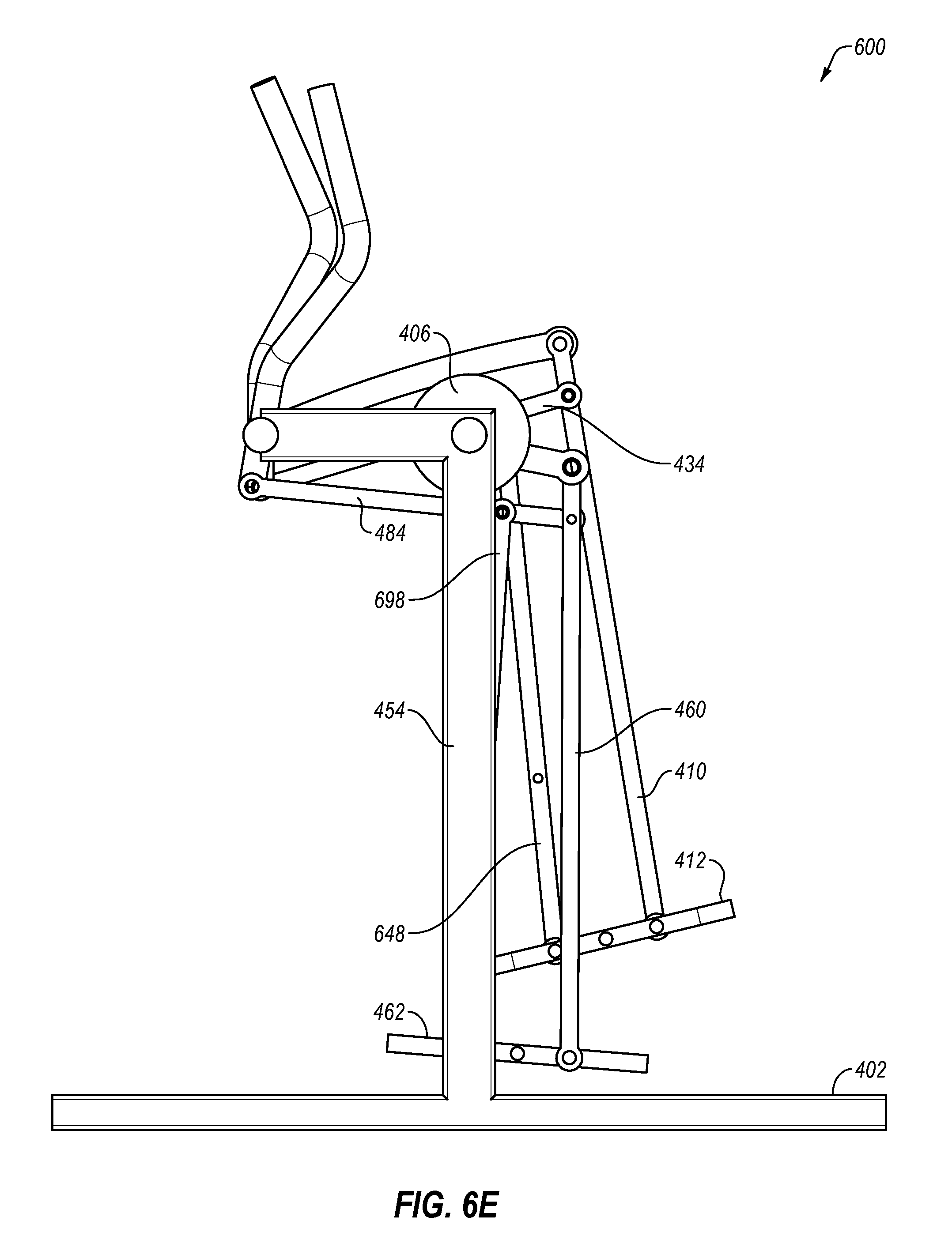
[0053] FIGS. 6A-6G are front-left, rear, right, front, left, top, and bottom perspective views, respectively, of a fourth example elliptical exercise machine 600. The machine 600 is similar to the machine 400, and therefore the discussion of the machine 600 will be limited to aspects of the machine 600 that differ from the machine 400.
[0054] The machine 600 supports the right crank 406 higher on right upright stanchion 404, and supports the left crank 456 higher on left upright stanchion 454, than the machine 400. Also, the machine 600 eliminates the timing cable 136, the right crank pulley 126, the upper and lower right timing pulleys 138 and 140, the left crank pulley 176, and the upper and lower left timing pulleys 188 and 190.
[0055] In addition, the machine 600 may include a second right pedal leg 648 supported by the right swing arm 434 and hanging downward from the right swing arm 434, with the second right pedal leg 648 further supporting the right pedal 412. Similarly, the machine 600 may include a second left pedal leg 698 supported by the left swing arm 484 and hanging downward from the left swing arm 484, with the second left pedal leg 698 further supporting the left pedal 462. By adding a second pedal leg supporting each pedal, differently shaped elliptical paths may be achieved (e.g., compare the shape of the elliptical path 500 of FIGS. 5A-5E to the shape of the elliptical path 700 of FIGS. 7A-7E).
[0056] FIGS. 7A-7E are left views of the fourth example elliptical exercise machine 600, illustrating an example elliptical path 700 of the fourth example elliptical exercise machine 600
[0057] During operation of the machine 600, the right pedal 412 may be configured to swing forward and rearward along the elliptical path 700 by a user's right foot striding forward and rearward with a length 702 of each swing determined by a length of the stride of the user's right foot. The right pedal 412 may be configured to raise upward and lower downward along the elliptical path 700 as the right crank arm 408 (see e.g., FIG. 6A) moves upward and downward during rotation of the right crank 406 (see e.g., FIG. 6A) Similarly, the left pedal 462 may be configured to swing forward and rearward along the elliptical path 700 by a user's left foot striding forward and rearward with a length 702 of each swing determined by a length of the stride of the user's left foot. The left pedal 462 may be configured to raise upward and lower downward along the elliptical path 700 as the left crank arm 458 (see e.g., FIG. 6D) moves upward and downward during rotation of the left crank 456.
[0058] The machine 600 may therefore allow for the elliptical path 700 to have a dynamically variable stride length 702 which allows the user to stride with a stride length that is comfortable to the user. Also, machine 600 may have a shorter front-to-back footprint than conventional elliptical exercise machines. This relatively shorter front-to-back footprint may result in at least a portion of the right pedal 412 being configured to swing rearward further than a rearmost portion of the base 402 (see, e.g., FIG. 7D) and at least a portion of the left pedal 462 being configured to swing rearward further than a rearmost portion of the base 402 (see, e.g., FIG. 7B).
[0059] FIGS. 8A-8G are front-left, rear, right, front, left, top, and bottom perspective views, respectively, of a fifth example elliptical exercise machine 800. The machine 800 is similar to the machine 600, and therefore the discussion of the machine 800 will be limited to aspects of the machine 800 that differ from the machine 600.
[0060] In place of the right roller arm 444 and the left roller arm 494 of the machine 600 (see FIG. 6A), the machine 800 may include a right roller arm 844 and a left roller arm 894. A surface of the right roller arm 844 that is configured to roll atop the right roller 446 may be curved and a surface of the left roller arm 894 that is configured to roll atop the left roller 496 may be curved. In the machine 800, each of these curved surfaces is a concave curved surface that is curved toward the corresponding roller. By curving the surface of each roller arm that rolls atop each roller, differently shaped elliptical paths may be achieved (e.g., compare the shape of the elliptical path 700 of FIGS. 7A-7E to the shape of the elliptical path 900 of FIGS. 9A-9E).
[0061] FIGS. 9A-9E are left views of the fifth example elliptical exercise machine 800, illustrating an example elliptical path 900 of the fifth example elliptical exercise machine 800.
[0062] During operation of the machine 800, the right pedal 412 may be configured to swing forward and rearward along the elliptical path 900 by a user's right foot striding forward and rearward with a length 902 of each swing determined by a length of the stride of the user's right foot. The right pedal 412 may be configured to raise upward and lower downward along the elliptical path 900 as the right crank arm 408 (see e.g., FIG. 8A) moves upward and downward during rotation of the right crank 406 (see e.g., FIG. 8A) Similarly, the left pedal 462 may be configured to swing forward and rearward along the elliptical path 900 by a user's left foot striding forward and rearward with a length 902 of each swing determined by a length of the stride of the user's left foot. The left pedal 462 may be configured to raise upward and lower downward along the elliptical path 900 as the left crank arm 458 (see e.g., FIG. 8F) moves upward and downward during rotation of the left crank 456.
[0063] The machine 800 may therefore allow for the elliptical path 900 to have a dynamically variable stride length 902 which allows the user to stride with a stride length that is comfortable to the user. Also, machine 800 may have a shorter front-to-back footprint than conventional elliptical exercise machines. This relatively shorter front-to-back footprint may result in at least a portion of the right pedal 412 being configured to swing rearward further than a rearmost portion of the base 402 (see, e.g., FIG. 9B) and at least a portion of the left pedal 462 being configured to swing rearward further than a rearmost portion of the base 402 (see, e.g., FIG. 9D).
INDUSTRIAL APPLICABILITY
[0064] In general, the example elliptical exercise machines disclosed herein may enable a dynamically variable stride length which allows the user to stride with a stride length that is comfortable to the user. Any variation in this dynamically variable stride length may be accomplished by a user simply taking a longer or shorter stride at any point during an exercise session. Further, the example elliptical exercise machines disclosed herein may take up relatively small amounts of floor space, which can make them easier to fit onto the floor space of an exercise area in a gym or a room in a home. This relatively small amount of floor space may be achieved by a relatively shorter front-to-back footprint that is accomplished, at least in part, by positioning the right and left cranks near the height of the user's hips, instead of positioning the right and left cranks down low near the user's feet as is done in most conventional elliptical exercise machines. Thus, the example elliptical exercise machines disclosed herein may overcome the shortcomings of conventional elliptical exercise machines, thereby enabling a more comfortable elliptical exercise for users while taking up less floor space in a gym or in a home.
[0065] Various modifications to the methods disclosed above will now be disclosed.
[0066] In the machine 800, the curved surfaces of the right roller arm 844 and the left roller arm 894 may be convex curved surfaces that are curved away from the corresponding rollers. By modifying the shape of these curved surfaces, differently shaped elliptical paths may be achieved.
[0067] Any of the example elliptical exercise machines disclosed herein may include a timing mechanism configured to cause the right crank arm to rotate about 180 degrees out of phase from the left crank arm. One example timing mechanism is the timing shaft 174 and associated belts and pulleys of the machine 100. Another example timing mechanism is the timing cable 136 and associated pulleys of the machines 200 and 400. It is understood that other example timing mechanisms that accomplish a similar result may be employed.
[0068] Additionally or alternatively, any of the example elliptical exercise machines disclosed herein may include a resistance mechanism configured to provide resistance to rotation of the right crank and/or the left crank. Where the right crank and the left crank are coupled together with a timing mechanism, providing resistance to either crank will effectively also provide resistance to the other crank via the timing mechanism. One example resistance mechanism is the flywheel 164 and associated belts and pulleys of the machine 100. It is understood that other example resistance mechanisms that accomplish a similar result may be employed. For example, the double-reduction pulley 168 may be eliminated from the resistance mechanism of the machine 100. Also, a magnetic brake may be employed on the machine 100 in connection with the flywheel 164 of the machine 100. The magnetic brake may be configured to provide variable resistance to the rotation of the flywheel 164. The magnetic brake may be any type of magnetic brake including an Eddy brake, a caliper brake with magnets on either side of the flywheel, a drum brake with magnets around the circumference of the flywheel, or a brake that only has magnets on one side of the flywheel. The magnets in the magnetic brake may be permanent magnets, or may be electro-magnets that require a power source in order to function. Further, instead of a magnetic brake, any other type of brake may be employed to provide variable resistance to the rotation of the flywheel 164, such as a friction brake (e.g., a strap or drum brake around the flywheel 164 or a caliper brake on the sides of the flywheel 164 that provide variable resistance to the rotation of the flywheel 164), an air brake (e.g., fan blades on the flywheel 164 that cause the air surrounding the flywheel 164 to resist the rotation of the flywheel 164), or a fluid brake (e.g., fan blades on the flywheel 164 that cause a fluid, such as water, contained in a container that surrounds the flywheel 164 to resist the rotation of the flywheel 164).
[0069] Additionally or alternatively, any of the example elliptical exercise machines disclosed herein may include an anti-skate mechanism configured to reduce or eliminate "skate" in the elliptical exercise machine. The term "skate" as used herein refers to the sensation where a pedal inadvertently extends farther forward or farther backward than is comfortable for the user, similar to the sensation one feels when a stride is uncomfortably and inadvertently lengthened for a user while wearing ice skates or roller skates. In some embodiments, an anti-skate mechanism may be implemented as part of a resistance mechanism, due to resistance on the right crank and/or the left crank tending to eliminate skate in the right and left pedals. Also, in some embodiments, an anti-skate mechanism may be implemented as part of a timing mechanism, due to coordination of the phases of the right crank and the left crank tending to eliminate skate in the right and left pedals. It is understood that other example anti-skate mechanisms that accomplish a similar result may be employed.
[0070] Additionally or alternatively, any of the example elliptical exercise machines disclosed herein may include a computer console configured to receive input from the user and provide output to the user, and/or configured to control the elliptical exercise machine. For example, the computer console may be employed in connection with the magnetic brake discussed above in order to allow the user to manually or programmatically alter the amount of resistance that the magnetic brake applies during the course of an exercise session on the elliptical exercise machine. The computer console may be configured to communicate over a network with other similar exercise machines, with servers, with computing devices of personal trainers, with sensors such as heart rate and respiration sensors, etc. Further, the computer console may be capable of downloading and uploading data in order to, for example, download and upload exercise sessions, data gathered at the elliptical exercise machine, data gathered at other exercise machines, etc. The computer console may enable a user of the elliptical exercise machine to compete with a user of another similar or dissimilar exercise machine, that is local to or remote from the user, with the competing users competing in real-time or at different times. Further, the computer console may be configured to track the amount of resistance provided by the magnetic brake to the flywheel, and the number or rotations of the flywheel, during an exercise session in order to compute the number of calories burned, the amount of energy expended, or any other metric desired by the user. Further, the computer console may be configured to track the number of strides taken by the user, as well as the length of each stride, in order to track the distance traveled by a user on the elliptical exercise machine during an exercise session. Further, all data tracked or downloaded by the computer console may be presented to the user on a display of the computer console.
[0071] Additionally or alternatively, any of the example elliptical exercise machines disclosed herein may include components moved from generally mirrored left-and-right positions to other positions, such as non-mirrored positions or center positions. For example, instead of left and right upright stanchions, any of the example elliptical exercise machines disclosed herein may instead include a single upright stanchion (perhaps positioned near the center of the base) that functions similarly to the left and right stanchions disclosed in the drawings. In another example, more than two upright stanchions may functions similarly to the left and right stanchions disclosed in the drawings. Therefore, the terms "left" and "right" as disclosed herein are for convenience only and are not intended to dictate generally mirrored left-and-right positions of components.
[0072] In accordance with common practice, the various features illustrated in the drawings may not be drawn to scale. The illustrations presented in the present disclosure are not meant to be actual views of any particular apparatus (e.g., device, system, etc.) or method, but are merely example representations that are employed to describe various embodiments of the disclosure. Accordingly, the dimensions of the various features may be arbitrarily expanded or reduced for clarity. In addition, some of the drawings may be simplified for clarity. Thus, the drawings may not depict all of the components of a given apparatus (e.g., device) or all operations of a particular method.
[0073] Terms used herein and especially in the appended claims (e.g., bodies of the appended claims) are generally intended as "open" terms (e.g., the term "including" should be interpreted as "including, but not limited to," the term "having" should be interpreted as "having at least," the term "includes" should be interpreted as "includes, but is not limited to," etc.).
[0074] Additionally, if a specific number of an introduced claim recitation is intended, such an intent will be explicitly recited in the claim, and in the absence of such recitation no such intent is present. For example, as an aid to understanding, the following appended claims may contain usage of the introductory phrases "at least one" and "one or more" to introduce claim recitations. However, the use of such phrases should not be construed to imply that the introduction of a claim recitation by the indefinite articles "a" or "an" limits any particular claim containing such introduced claim recitation to embodiments containing only one such recitation, even when the same claim includes the introductory phrases "one or more" or "at least one" and indefinite articles such as "a" or "an" (e.g., "a" and/or "an" should be interpreted to mean "at least one" or "one or more"); the same holds true for the use of definite articles used to introduce claim recitations.
[0075] In addition, even if a specific number of an introduced claim recitation is explicitly recited, it is understood that such recitation should be interpreted to mean at least the recited number (e.g., the bare recitation of "two recitations," without other modifiers, means at least two recitations, or two or more recitations). Furthermore, in those instances where a convention analogous to "at least one of A, B, and C, etc." or "one or more of A, B, and C, etc." is used, in general such a construction is intended to include A alone, B alone, C alone, A and B together, A and C together, B and C together, or A, B, and C together, etc. For example, the use of the term "and/or" is intended to be construed in this manner.
[0076] Further, any disjunctive word or phrase presenting two or more alternative terms, whether in the summary, detailed description, claims, or drawings, should be understood to contemplate the possibilities of including one of the terms, either of the terms, or both terms. For example, the phrase "A or B" should be understood to include the possibilities of "A" or "B" or "A and B."
[0077] Additionally, the use of the terms "first," "second," "third," etc., are not necessarily used herein to connote a specific order or number of elements. Generally, the terms "first," "second," "third," etc., are used to distinguish between different elements as generic identifiers. Absence a showing that the terms "first," "second," "third," etc., connote a specific order, these terms should not be understood to connote a specific order. Furthermore, absence a showing that the terms first," "second," "third," etc., connote a specific number of elements, these terms should not be understood to connote a specific number of elements. For example, a first widget may be described as having a first side and a second widget may be described as having a second side. The use of the term "second side" with respect to the second widget may be to distinguish such side of the second widget from the "first side" of the first widget and not to connote that the second widget has two sides.
[0078] The foregoing description, for purpose of explanation, has been described with reference to specific embodiments. However, the illustrative discussions above are not intended to be exhaustive or to limit the invention as claimed to the precise forms disclosed. Many modifications and variations are possible in view of the above teachings. The embodiments were chosen and described to explain practical applications, to thereby enable others skilled in the art to utilize the invention as claimed and various embodiments with various modifications as may be suited to the particular use contemplated.
* * * * *
D00000
D00001
D00002
D00003
D00004
D00005
D00006
D00007
D00008
D00009
D00010
D00011
D00012

D00013

D00014

D00015

D00016

D00017

D00018

D00019

D00020

D00021

D00022

D00023

D00024
D00025

D00026

D00027

D00028

D00029

D00030

D00031

D00032

D00033

D00034

D00035

D00036
D00037

D00038

D00039

D00040

D00041

D00042

D00043

D00044

D00045

D00046

D00047

D00048

D00049

D00050

D00051

D00052

D00053

D00054

D00055

XML
uspto.report is an independent third-party trademark research tool that is not affiliated, endorsed, or sponsored by the United States Patent and Trademark Office (USPTO) or any other governmental organization. The information provided by uspto.report is based on publicly available data at the time of writing and is intended for informational purposes only.
While we strive to provide accurate and up-to-date information, we do not guarantee the accuracy, completeness, reliability, or suitability of the information displayed on this site. The use of this site is at your own risk. Any reliance you place on such information is therefore strictly at your own risk.
All official trademark data, including owner information, should be verified by visiting the official USPTO website at www.uspto.gov. This site is not intended to replace professional legal advice and should not be used as a substitute for consulting with a legal professional who is knowledgeable about trademark law.