Electrical ablation devices
Long , et al. Sept
U.S. patent number 10,779,882 [Application Number 15/250,507] was granted by the patent office on 2020-09-22 for electrical ablation devices. This patent grant is currently assigned to ETHICON ENDO-SURGERY, INC.. The grantee listed for this patent is Ethicon Endo-Surgery, Inc.. Invention is credited to Gary L. Long, David N. Plescia, Omar J. Vakharia.


| United States Patent | 10,779,882 |
| Long , et al. | September 22, 2020 |
Electrical ablation devices
Abstract
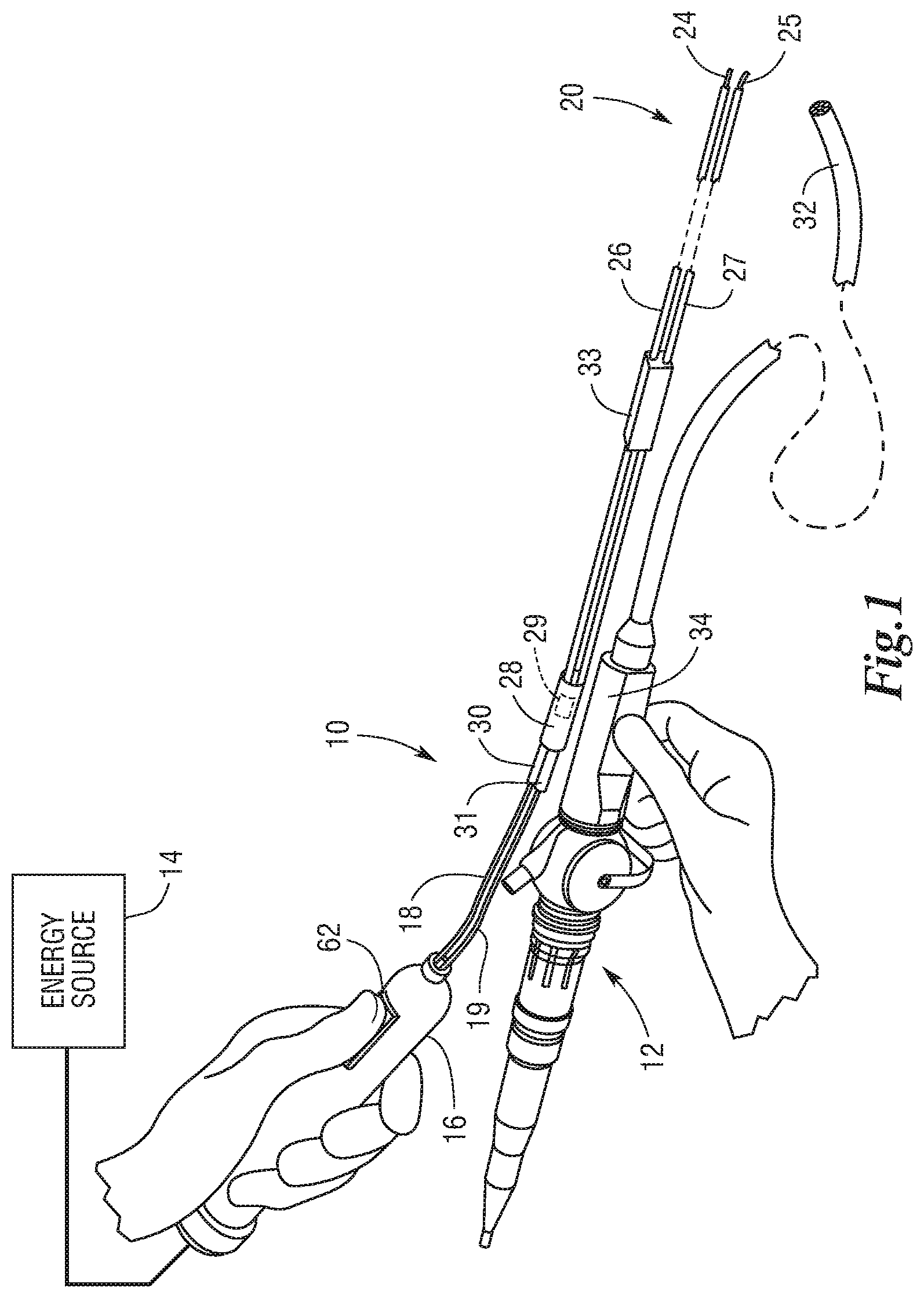
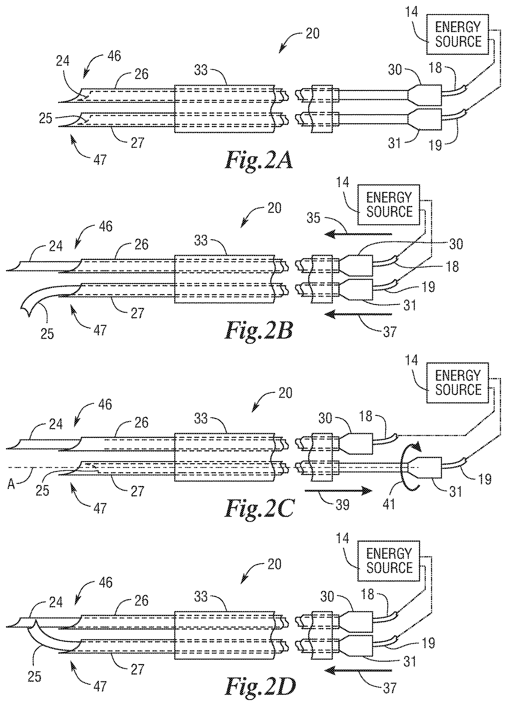
An electrical ablation apparatus including first, second, and third electrodes is disclosed. Each of the first and second electrode is configured to be selectively extended outside and selectively retracted inside a distal end of its respective lumen and is configured to diverge from its respective longitudinal axis when extended outside the distal end of its respective lumen. The third electrode is non-rotatable and is configured to be selectively extended outside and selectively retracted inside a distal end of its respective lumen. The first, second and third electrodes are extendable into a tissue treatment region to create a first necrotic zone having a first shape. At least one of the first electrode or the second electrode is selectively rotatable within its respective lumen to create a second necrotic zone having a second shape. The third electrode is configured to positionally secure the electrical ablation apparatus at the tissue treatment region.
| Inventors: | Long; Gary L. (Cincinnati, OH), Plescia; David N. (Mentor, OH), Vakharia; Omar J. (Cincinnati, OH) | ||||||||||
|---|---|---|---|---|---|---|---|---|---|---|---|
| Applicant: |
|
||||||||||
| Assignee: | ETHICON ENDO-SURGERY, INC.
(Cincinnati, OH) |
||||||||||
| Family ID: | 1000005067017 | ||||||||||
| Appl. No.: | 15/250,507 | ||||||||||
| Filed: | August 29, 2016 |
Prior Publication Data
| Document Identifier | Publication Date | |
|---|---|---|
| US 20170049508 A1 | Feb 23, 2017 | |
Related U.S. Patent Documents
| Application Number | Filing Date | Patent Number | Issue Date | ||
|---|---|---|---|---|---|
| 12607252 | Oct 28, 2009 | ||||
| Current U.S. Class: | 1/1 |
| Current CPC Class: | A61B 18/1492 (20130101); A61B 90/08 (20160201); A61N 1/327 (20130101); A61B 18/1477 (20130101); A61B 2018/1475 (20130101); A61B 2018/0022 (20130101); A61B 2018/00577 (20130101); A61B 2018/143 (20130101); A61B 2090/0811 (20160201); A61B 2018/00898 (20130101); A61B 2018/00214 (20130101); A61B 2018/1425 (20130101); A61B 2018/1467 (20130101); A61B 18/1815 (20130101) |
| Current International Class: | A61B 18/14 (20060101); A61B 90/00 (20160101); A61N 1/32 (20060101); A61B 18/00 (20060101); A61B 18/18 (20060101) |
References Cited [Referenced By]
U.S. Patent Documents
| 112794 | March 1871 | Felton |
| 645576 | March 1900 | Tesla |
| 649621 | May 1900 | Tesla |
| 787412 | April 1905 | Tesla |
| 1039354 | September 1912 | Bonadio |
| 1127948 | February 1915 | Wappler |
| 1330147 | February 1920 | Stitzer |
| 1330205 | February 1920 | McKeehan |
| 1335331 | March 1920 | Gunderson |
| 1440116 | December 1922 | Telfer |
| 1482653 | February 1924 | Lilly |
| 1581706 | April 1926 | White |
| 1581707 | April 1926 | White |
| 1581708 | April 1926 | White |
| 1581709 | April 1926 | White |
| 1581710 | April 1926 | White |
| 1625602 | April 1927 | Gould |
| 1892018 | December 1932 | Stanton |
| 1916722 | July 1933 | Ende |
| 2028635 | January 1936 | Wappler |
| 2031682 | February 1936 | Wappler |
| 2113246 | April 1938 | Wappler |
| 2137710 | November 1938 | Anderson |
| 2155365 | April 1939 | Rankin |
| 2191858 | February 1940 | Moore |
| 2196620 | April 1940 | Attarian |
| 2303961 | December 1942 | Sprague |
| 2330120 | September 1943 | Hagelstein |
| 2388137 | October 1945 | Graumlich |
| 2409379 | October 1946 | Mosaly |
| 2451077 | October 1948 | Emsig |
| 2493108 | January 1950 | Casey |
| 2504152 | April 1950 | Riker |
| 2514698 | July 1950 | Herrero |
| 2514951 | July 1950 | Herndon |
| 2644210 | July 1953 | McNamee |
| 2938382 | May 1960 | De Graaf |
| 2952206 | September 1960 | Becksted |
| 3044461 | July 1962 | Murdock |
| 3069195 | December 1962 | Buck |
| 3070088 | December 1962 | Brahos |
| 3110956 | November 1963 | Fischer, Jr. |
| 3170471 | February 1965 | Schnitzer |
| 3435824 | April 1969 | Gamponia |
| 3470876 | October 1969 | Barchilon |
| 3481325 | December 1969 | Glassman |
| 3543760 | December 1970 | Bolduc |
| 3595239 | July 1971 | Petersen |
| 3669487 | June 1972 | Roberts et al. |
| 3746881 | July 1973 | Fitch et al. |
| 3799672 | March 1974 | Vurek |
| 3854473 | December 1974 | Matsuo |
| 3854743 | December 1974 | Hansen |
| 3929123 | December 1975 | Jamshidi |
| 3946740 | March 1976 | Bassett |
| 3948251 | April 1976 | Hosono |
| 3961632 | June 1976 | Moossun |
| 3965890 | June 1976 | Gauthier |
| 3994301 | November 1976 | Agris |
| 4011872 | March 1977 | Komiya |
| 4012812 | March 1977 | Black |
| 4043342 | August 1977 | Morrison, Jr. |
| 4071028 | January 1978 | Perkins |
| 4085743 | April 1978 | Yoon |
| 4164225 | August 1979 | Johnson et al. |
| 4170997 | October 1979 | Pinnow et al. |
| 4174715 | November 1979 | Hasson |
| 4178920 | December 1979 | Cawood, Jr. et al. |
| 4207873 | June 1980 | Kruy |
| 4235238 | November 1980 | Ogiu et al. |
| 4258716 | March 1981 | Sutherland |
| 4269174 | May 1981 | Adair |
| 4278077 | July 1981 | Mizumoto |
| 4281646 | August 1981 | Kinoshita |
| 4285344 | August 1981 | Marshall |
| 4311143 | January 1982 | Komiya |
| 4329980 | May 1982 | Terada |
| 4393872 | July 1983 | Reznik et al. |
| 4394791 | July 1983 | Groth |
| 4396021 | August 1983 | Baumgartner |
| 4396139 | August 1983 | Hall et al. |
| 4406656 | September 1983 | Hattler et al. |
| 4452246 | June 1984 | Bader et al. |
| 4461281 | July 1984 | Carson |
| 4491132 | January 1985 | Aikins |
| 4491135 | January 1985 | Klein |
| 4492232 | January 1985 | Green |
| 4527331 | July 1985 | Lasner et al. |
| 4527564 | July 1985 | Eguchi et al. |
| 4538594 | September 1985 | Boebel et al. |
| D281104 | October 1985 | Davison |
| 4569347 | February 1986 | Frisbie |
| 4580551 | April 1986 | Siegmund et al. |
| 4646722 | March 1987 | Silverstein et al. |
| 4649904 | March 1987 | Krauter et al. |
| 4653476 | March 1987 | Bonnet |
| 4655219 | April 1987 | Petruzzi |
| 4657016 | April 1987 | Garito et al. |
| 4657018 | April 1987 | Hakky |
| 4669470 | June 1987 | Brandfield |
| 4671477 | June 1987 | Cullen |
| 4677982 | July 1987 | Llinas et al. |
| 4685447 | August 1987 | Iversen et al. |
| 4711239 | December 1987 | Sorochenko et al. |
| 4711240 | December 1987 | Goldwasser et al. |
| 4712545 | December 1987 | Honkanen |
| 4721116 | January 1988 | Schintgen et al. |
| 4727600 | February 1988 | Avakian |
| 4733662 | March 1988 | DeSatnick et al. |
| D295894 | May 1988 | Sharkany et al. |
| 4742817 | May 1988 | Kawashima et al. |
| 4753223 | June 1988 | Bremer |
| 4763669 | August 1988 | Jaeger |
| 4770188 | September 1988 | Chikama |
| 4790624 | December 1988 | Van Hoye et al. |
| 4791707 | December 1988 | Tucker |
| 4796627 | January 1989 | Tucker |
| 4807593 | February 1989 | Ito |
| 4815450 | March 1989 | Patel |
| 4819620 | April 1989 | Okutsu |
| 4823794 | April 1989 | Pierce |
| 4829999 | May 1989 | Auth |
| 4836188 | June 1989 | Berry |
| 4846573 | July 1989 | Taylor et al. |
| 4867140 | September 1989 | Hovis et al. |
| 4869238 | September 1989 | Opie et al. |
| 4869459 | September 1989 | Bourne |
| 4873979 | October 1989 | Hanna |
| 4880015 | November 1989 | Nierman |
| 4904048 | February 1990 | Sogawa et al. |
| 4911148 | March 1990 | Sosnowski et al. |
| 4926860 | May 1990 | Stice et al. |
| 4934364 | June 1990 | Green |
| 4938214 | July 1990 | Specht et al. |
| 4950273 | August 1990 | Briggs |
| 4950285 | August 1990 | Wilk |
| 4953539 | September 1990 | Nakamura et al. |
| 4960133 | October 1990 | Hewson |
| 4977887 | December 1990 | Gouda |
| 4979496 | December 1990 | Komi |
| 4979950 | December 1990 | Transue et al. |
| 4984581 | January 1991 | Stice |
| 4990152 | February 1991 | Yoon |
| 4991565 | February 1991 | Takahashi et al. |
| 4994079 | February 1991 | Genese et al. |
| 5007917 | April 1991 | Evans |
| 5010876 | April 1991 | Henley et al. |
| 5015249 | May 1991 | Nakao et al. |
| 5020514 | June 1991 | Heckele |
| 5020535 | June 1991 | Parker et al. |
| 5025778 | June 1991 | Silverstein et al. |
| 5026379 | June 1991 | Yoon |
| 5033169 | July 1991 | Bindon |
| 5037433 | August 1991 | Wilk et al. |
| 5041129 | August 1991 | Hayhurst et al. |
| 5046513 | September 1991 | Gatturna et al. |
| 5049153 | September 1991 | Nakao et al. |
| 5050585 | September 1991 | Takahashi |
| 5052372 | October 1991 | Shapiro |
| 5065516 | November 1991 | Dulebohn |
| 5066295 | November 1991 | Kozak et al. |
| 5098378 | March 1992 | Piontek et al. |
| 5099827 | March 1992 | Melzer et al. |
| 5108421 | April 1992 | Fowler |
| 5123913 | June 1992 | Wilk et al. |
| 5123914 | June 1992 | Cope |
| 5133727 | July 1992 | Bales et al. |
| 5147374 | September 1992 | Fernandez |
| 5156151 | October 1992 | Imran |
| 5156609 | October 1992 | Nakao et al. |
| 5174300 | December 1992 | Bales et al. |
| 5176126 | January 1993 | Chikama |
| 5190050 | March 1993 | Nitzsche |
| 5190555 | March 1993 | Wetter et al. |
| 5192284 | March 1993 | Pleatman |
| 5192300 | March 1993 | Fowler |
| 5197963 | March 1993 | Parins |
| 5201752 | April 1993 | Brown et al. |
| 5201908 | April 1993 | Jones |
| 5203785 | April 1993 | Slater |
| 5203787 | April 1993 | Noblitt et al. |
| 5209747 | May 1993 | Knoepfler |
| 5217003 | June 1993 | Wilk |
| 5217453 | June 1993 | Wilk |
| 5219357 | June 1993 | Honkanen et al. |
| 5219358 | June 1993 | Bendel et al. |
| 5222362 | June 1993 | Maus et al. |
| 5222961 | June 1993 | Nakao et al. |
| 5222965 | June 1993 | Haughton |
| 5224946 | July 1993 | Hayhurst et al. |
| 5234437 | August 1993 | Sepetka |
| 5234453 | August 1993 | Smith et al. |
| 5235964 | August 1993 | Abenaim |
| 5242456 | September 1993 | Nash et al. |
| 5245460 | September 1993 | Allen et al. |
| 5246424 | September 1993 | Wilk |
| 5254130 | October 1993 | Poncet et al. |
| 5257999 | November 1993 | Slanetz, Jr. |
| 5259366 | November 1993 | Reydel et al. |
| 5263958 | November 1993 | deGuillebon et al. |
| 5273524 | December 1993 | Fox et al. |
| 5275607 | January 1994 | Lo et al. |
| 5275614 | January 1994 | Haber et al. |
| 5275616 | January 1994 | Fowler |
| 5284128 | February 1994 | Hart |
| 5284162 | February 1994 | Wilk |
| 5287845 | February 1994 | Faul et al. |
| 5287852 | February 1994 | Arkinstall |
| 5290299 | March 1994 | Fain et al. |
| 5290302 | March 1994 | Pericic |
| 5295977 | March 1994 | Cohen et al. |
| 5297536 | March 1994 | Wilk |
| 5297687 | March 1994 | Freed |
| 5301061 | April 1994 | Nakada et al. |
| 5308327 | May 1994 | Heaven et al. |
| 5312023 | May 1994 | Green et al. |
| 5312333 | May 1994 | Churinetz et al. |
| 5312351 | May 1994 | Gerrone |
| 5312416 | May 1994 | Spaeth et al. |
| 5312423 | May 1994 | Rosenbluth et al. |
| 5318589 | June 1994 | Lichtman |
| 5320636 | June 1994 | Slater |
| 5324261 | June 1994 | Amundson et al. |
| 5325845 | July 1994 | Adair |
| 5330471 | July 1994 | Eggers |
| 5330486 | July 1994 | Wilk |
| 5330488 | July 1994 | Goldrath |
| 5330496 | July 1994 | Alferness |
| 5330502 | July 1994 | Hassler et al. |
| 5331971 | July 1994 | Bales et al. |
| 5334168 | August 1994 | Hemmer |
| 5334198 | August 1994 | Hart et al. |
| 5336192 | August 1994 | Palestrant |
| 5336222 | August 1994 | Durgin, Jr. et al. |
| 5339805 | August 1994 | Parker |
| 5341815 | August 1994 | Cofone et al. |
| 5342396 | August 1994 | Cook |
| 5344428 | September 1994 | Griffiths |
| 5345927 | September 1994 | Bonutti |
| 5348259 | September 1994 | Blanco et al. |
| 5350391 | September 1994 | Iacovelli |
| 5352184 | October 1994 | Goldberg et al. |
| 5352222 | October 1994 | Rydell |
| 5354302 | October 1994 | Ko |
| 5354311 | October 1994 | Kambin et al. |
| 5356381 | October 1994 | Ensminger et al. |
| 5356408 | October 1994 | Rydell |
| 5360428 | November 1994 | Hutchinson, Jr. |
| 5364408 | November 1994 | Gordon |
| 5364410 | November 1994 | Failla et al. |
| 5366466 | November 1994 | Christian et al. |
| 5366467 | November 1994 | Lynch et al. |
| 5368605 | November 1994 | Miller, Jr. |
| 5368606 | November 1994 | Marlow et al. |
| 5370647 | December 1994 | Graber et al. |
| 5370679 | December 1994 | Atlee, III |
| 5374273 | December 1994 | Nakao et al. |
| 5374275 | December 1994 | Bradley et al. |
| 5374277 | December 1994 | Hassler |
| 5374953 | December 1994 | Sasaki et al. |
| 5376077 | December 1994 | Gomringer |
| 5377695 | January 1995 | An Haack |
| 5378234 | January 1995 | Hammerslag et al. |
| 5383877 | January 1995 | Clarke |
| 5383888 | January 1995 | Zvenyatsky et al. |
| 5386817 | February 1995 | Jones |
| 5387259 | February 1995 | Davidson |
| 5391174 | February 1995 | Weston |
| 5392789 | February 1995 | Slater et al. |
| 5395367 | March 1995 | Wilk |
| 5395381 | March 1995 | Green et al. |
| 5395386 | March 1995 | Slater |
| 5397332 | March 1995 | Kammerer et al. |
| 5401248 | March 1995 | Bencini |
| 5403311 | April 1995 | Abele et al. |
| 5403326 | April 1995 | Harrison et al. |
| 5403328 | April 1995 | Shallman |
| 5403342 | April 1995 | Tovey et al. |
| 5403348 | April 1995 | Bonutti |
| 5405073 | April 1995 | Porter |
| 5405359 | April 1995 | Pierce |
| 5409478 | April 1995 | Gerry et al. |
| 5417699 | May 1995 | Klein et al. |
| 5423821 | June 1995 | Pasque |
| 5431635 | July 1995 | Yoon |
| 5433721 | July 1995 | Hooven et al. |
| 5433735 | July 1995 | Zanakis et al. |
| 5439471 | August 1995 | Kerr |
| 5439478 | August 1995 | Palmer |
| 5441059 | August 1995 | Dannan |
| 5441494 | August 1995 | Ortiz |
| 5441498 | August 1995 | Perkins |
| 5441499 | August 1995 | Fritzsch |
| 5443463 | August 1995 | Stern et al. |
| 5445638 | August 1995 | Rydell et al. |
| 5445648 | August 1995 | Cook |
| 5449021 | September 1995 | Chikama |
| 5454827 | October 1995 | Aust et al. |
| 5456667 | October 1995 | Ham et al. |
| 5456684 | October 1995 | Schmidt et al. |
| 5458131 | October 1995 | Wilk |
| 5458583 | October 1995 | McNeely et al. |
| 5460168 | October 1995 | Masubuchi et al. |
| 5460629 | October 1995 | Shlain et al. |
| 5462561 | October 1995 | Voda |
| 5465731 | November 1995 | Bell et al. |
| 5467763 | November 1995 | McMahon et al. |
| 5468250 | November 1995 | Paraschac et al. |
| 5470308 | November 1995 | Edwards et al. |
| 5470320 | November 1995 | Tiefenbrun et al. |
| 5472441 | December 1995 | Edwards et al. |
| 5478347 | December 1995 | Aranyi |
| 5478352 | December 1995 | Fowler |
| 5480404 | January 1996 | Kammerer et al. |
| 5482029 | January 1996 | Sekiguchi et al. |
| 5482054 | January 1996 | Slater et al. |
| 5484451 | January 1996 | Akopov et al. |
| 5489256 | February 1996 | Adair |
| 5496347 | March 1996 | Hashiguchi et al. |
| 5499990 | March 1996 | Schulken et al. |
| 5499992 | March 1996 | Meade et al. |
| 5499997 | March 1996 | Sharpe et al. |
| 5500012 | March 1996 | Brucker et al. |
| 5501692 | March 1996 | Riza |
| 5503616 | April 1996 | Jones |
| 5505686 | April 1996 | Willis et al. |
| 5507755 | April 1996 | Gresl et al. |
| 5511564 | April 1996 | Wilk |
| 5514157 | May 1996 | Nicholas et al. |
| 5518501 | May 1996 | Oneda et al. |
| 5522829 | June 1996 | Michalos |
| 5522830 | June 1996 | Aranyi |
| 5524633 | June 1996 | Heaven et al. |
| 5527321 | June 1996 | Hinchliffe |
| 5533418 | July 1996 | Wu et al. |
| 5536234 | July 1996 | Newman |
| 5536248 | July 1996 | Weaver et al. |
| 5538509 | July 1996 | Dunlap et al. |
| 5540648 | July 1996 | Yoon |
| 5549637 | August 1996 | Crainich |
| 5554151 | September 1996 | Hinchliffe |
| 5555883 | September 1996 | Avitall |
| 5558133 | September 1996 | Bortoli et al. |
| 5562693 | October 1996 | Devlin et al. |
| 5569243 | October 1996 | Kortenbach et al. |
| 5569298 | October 1996 | Schnell |
| 5571090 | November 1996 | Sherts |
| 5573540 | November 1996 | Yoon |
| 5578030 | November 1996 | Levin |
| 5582611 | December 1996 | Tsuruta et al. |
| 5582617 | December 1996 | Klieman et al. |
| 5584845 | December 1996 | Hart |
| 5590660 | January 1997 | MacAulay et al. |
| 5591179 | January 1997 | Edelstein |
| 5591205 | January 1997 | Fowler |
| 5593420 | January 1997 | Eubanks, Jr. et al. |
| 5595562 | January 1997 | Grier |
| 5597378 | January 1997 | Jervis |
| 5601573 | February 1997 | Fogelberg et al. |
| 5601574 | February 1997 | Stefanchik et al. |
| 5601588 | February 1997 | Tonomura et al. |
| 5601602 | February 1997 | Fowler |
| 5604531 | February 1997 | Iddan et al. |
| 5607386 | March 1997 | Flam |
| 5607389 | March 1997 | Edwards et al. |
| 5607406 | March 1997 | Hernandez et al. |
| 5607450 | March 1997 | Zvenyatsky et al. |
| 5609601 | March 1997 | Kolesa et al. |
| 5613975 | March 1997 | Christy |
| 5613977 | March 1997 | Weber et al. |
| 5614943 | March 1997 | Nakamura et al. |
| 5616117 | April 1997 | Dinkler et al. |
| 5618303 | April 1997 | Marlow et al. |
| 5620415 | April 1997 | Lucey et al. |
| 5624399 | April 1997 | Ackerman |
| 5624431 | April 1997 | Gerry et al. |
| 5626578 | May 1997 | Tihon |
| 5626587 | May 1997 | Bishop et al. |
| 5628732 | May 1997 | Antoon, Jr. et al. |
| 5630782 | May 1997 | Adair |
| 5630795 | May 1997 | Kuramoto et al. |
| 5643283 | July 1997 | Younker |
| 5643292 | July 1997 | Hart |
| 5643294 | July 1997 | Tovey et al. |
| 5644798 | July 1997 | Shah |
| 5645083 | July 1997 | Essig et al. |
| 5645519 | July 1997 | Lee et al. |
| 5645565 | July 1997 | Rudd et al. |
| 5649372 | July 1997 | Souza |
| 5653677 | August 1997 | Okada et al. |
| 5653690 | August 1997 | Booth et al. |
| 5653722 | August 1997 | Kieturakis |
| 5657755 | August 1997 | Desai |
| 5662621 | September 1997 | Lafontaine |
| 5662663 | September 1997 | Shallman |
| 5665096 | September 1997 | Yoon |
| 5665100 | September 1997 | Yoon |
| 5667527 | September 1997 | Cook |
| 5669875 | September 1997 | van Eerdenburg |
| 5681276 | October 1997 | Lundquist |
| 5681279 | October 1997 | Roper et al. |
| 5681324 | October 1997 | Kammerer et al. |
| 5681330 | October 1997 | Hughett et al. |
| 5685820 | November 1997 | Riek et al. |
| 5688269 | November 1997 | Newton et al. |
| 5690606 | November 1997 | Slotman |
| 5690656 | November 1997 | Cope et al. |
| 5690660 | November 1997 | Kauker et al. |
| 5695448 | December 1997 | Kimura et al. |
| 5695505 | December 1997 | Yoon |
| 5695511 | December 1997 | Cano et al. |
| 5700275 | December 1997 | Bell et al. |
| 5702438 | December 1997 | Avitall |
| 5704892 | January 1998 | Adair |
| 5709708 | January 1998 | Thal |
| 5711921 | January 1998 | Langford |
| 5716326 | February 1998 | Dannan |
| 5716375 | February 1998 | Fowler |
| 5725542 | March 1998 | Yoon |
| 5728094 | March 1998 | Edwards |
| 5730740 | March 1998 | Wales et al. |
| 5735849 | April 1998 | Baden et al. |
| 5741234 | April 1998 | Aboul-Hosn |
| 5741278 | April 1998 | Stevens |
| 5741285 | April 1998 | McBrayer et al. |
| 5741429 | April 1998 | Donadio, III et al. |
| 5743456 | April 1998 | Jones et al. |
| 5746759 | May 1998 | Meade et al. |
| 5749826 | May 1998 | Faulkner |
| 5749881 | May 1998 | Sackier et al. |
| 5749889 | May 1998 | Bacich et al. |
| 5752951 | May 1998 | Yanik |
| 5755731 | May 1998 | Grinberg |
| 5759150 | June 1998 | Konou et al. |
| 5759151 | June 1998 | Sturges |
| 5762604 | June 1998 | Kieturakis |
| 5766167 | June 1998 | Eggers et al. |
| 5766170 | June 1998 | Eggers |
| 5766205 | June 1998 | Zvenyatsky et al. |
| 5769849 | June 1998 | Eggers |
| 5776188 | July 1998 | Shepherd et al. |
| 5779701 | July 1998 | McBrayer et al. |
| 5779716 | July 1998 | Cano et al. |
| 5779720 | July 1998 | Walder-Utz et al. |
| 5779727 | July 1998 | Orejola |
| 5782748 | July 1998 | Palmer et al. |
| 5782859 | July 1998 | Nicholas et al. |
| 5782861 | July 1998 | Cragg et al. |
| 5782866 | July 1998 | Wenstrom, Jr. |
| 5791022 | August 1998 | Bohman |
| 5792113 | August 1998 | Kramer et al. |
| 5792153 | August 1998 | Swain et al. |
| 5792165 | August 1998 | Klieman et al. |
| 5797835 | August 1998 | Green |
| 5797928 | August 1998 | Kogasaka |
| 5797939 | August 1998 | Yoon |
| 5797941 | August 1998 | Schulze et al. |
| 5797959 | August 1998 | Castro et al. |
| 5797960 | August 1998 | Stevens et al. |
| 5800449 | September 1998 | Wales |
| 5800451 | September 1998 | Buess et al. |
| 5803903 | September 1998 | Athas et al. |
| 5807395 | September 1998 | Mulier et al. |
| 5808665 | September 1998 | Green |
| 5810805 | September 1998 | Sutcu et al. |
| 5810806 | September 1998 | Ritchart et al. |
| 5810849 | September 1998 | Kontos |
| 5810865 | September 1998 | Koscher et al. |
| 5810876 | September 1998 | Kelleher |
| 5810877 | September 1998 | Roth et al. |
| 5813976 | September 1998 | Filipi et al. |
| 5814026 | September 1998 | Yoon |
| 5814058 | September 1998 | Carlson et al. |
| 5817061 | October 1998 | Goodwin et al. |
| 5817107 | October 1998 | Schaller |
| 5817108 | October 1998 | Poncet |
| 5817119 | October 1998 | Klieman et al. |
| 5818527 | October 1998 | Yamaguchi et al. |
| 5819736 | October 1998 | Avny et al. |
| 5823947 | October 1998 | Yoon et al. |
| 5824071 | October 1998 | Nelson et al. |
| 5827190 | October 1998 | Palcic et al. |
| 5827276 | October 1998 | LeVeen et al. |
| 5827281 | October 1998 | Levin |
| 5827299 | October 1998 | Thomason et al. |
| 5827323 | October 1998 | Klieman et al. |
| 5830221 | November 1998 | Stein et al. |
| 5830231 | November 1998 | Geiges, Jr. |
| 5833603 | November 1998 | Kovacs et al. |
| 5833700 | November 1998 | Fogelberg et al. |
| 5833703 | November 1998 | Manushakian |
| 5833715 | November 1998 | Vachon et al. |
| 5836960 | November 1998 | Kolesa et al. |
| 5843017 | December 1998 | Yoon |
| 5843097 | December 1998 | Mayenberger et al. |
| 5843121 | December 1998 | Yoon |
| 5843156 | December 1998 | Slepian et al. |
| 5848986 | December 1998 | Lundquist et al. |
| 5849022 | December 1998 | Sakashita et al. |
| 5853374 | December 1998 | Hart et al. |
| 5855569 | January 1999 | Komi |
| 5855585 | January 1999 | Kontos |
| 5860913 | January 1999 | Yamaya et al. |
| 5860995 | January 1999 | Berkelaar |
| 5868762 | February 1999 | Cragg et al. |
| 5873849 | February 1999 | Bernard |
| 5876411 | March 1999 | Kontos |
| 5882331 | March 1999 | Sasaki |
| 5882344 | March 1999 | Stouder, Jr. |
| 5885280 | March 1999 | Nettekoven et al. |
| 5893846 | April 1999 | Bales et al. |
| 5893874 | April 1999 | Bourque et al. |
| 5893875 | April 1999 | O'Connor et al. |
| 5897487 | April 1999 | Ouchi |
| 5899919 | May 1999 | Eubanks, Jr. et al. |
| 5902238 | May 1999 | Golden et al. |
| 5902254 | May 1999 | Magram |
| 5904702 | May 1999 | Ek et al. |
| 5906625 | May 1999 | Bito et al. |
| 5908420 | June 1999 | Parins et al. |
| 5908429 | June 1999 | Yoon |
| 5911737 | June 1999 | Lee et al. |
| 5916146 | June 1999 | Allotta et al. |
| 5916147 | June 1999 | Boury |
| 5919207 | July 1999 | Taheri |
| 5921892 | July 1999 | Easton |
| 5921993 | July 1999 | Yoon |
| 5921997 | July 1999 | Fogelberg et al. |
| 5922008 | July 1999 | Gimpelson |
| 5925052 | July 1999 | Simmons |
| 5928255 | July 1999 | Meade et al. |
| 5928266 | July 1999 | Kontos |
| 5936536 | August 1999 | Morris |
| 5938661 | August 1999 | Hahnen |
| 5938668 | August 1999 | Scirica et al. |
| 5941815 | August 1999 | Chang |
| 5944718 | August 1999 | Austin et al. |
| 5951547 | September 1999 | Gough et al. |
| 5951549 | September 1999 | Richardson et al. |
| 5954720 | September 1999 | Wilson et al. |
| 5954731 | September 1999 | Yoon |
| 5957936 | September 1999 | Yoon et al. |
| 5957943 | September 1999 | Vaitekunas |
| 5957953 | September 1999 | DiPoto et al. |
| 5964782 | October 1999 | Lafontaine et al. |
| 5970581 | October 1999 | Chadwick et al. |
| 5971995 | October 1999 | Rousseau |
| 5972002 | October 1999 | Bark et al. |
| 5976074 | November 1999 | Moriyama |
| 5976075 | November 1999 | Beane et al. |
| 5976130 | November 1999 | McBrayer et al. |
| 5976131 | November 1999 | Guglielmi et al. |
| 5980539 | November 1999 | Kontos |
| 5980556 | November 1999 | Giordano et al. |
| 5984933 | November 1999 | Yoon |
| 5984938 | November 1999 | Yoon |
| 5984939 | November 1999 | Yoon |
| 5984950 | November 1999 | Cragg et al. |
| 5989182 | November 1999 | Hori et al. |
| 5993447 | November 1999 | Blewett et al. |
| 5993474 | November 1999 | Ouchi |
| 5995875 | November 1999 | Blewett et al. |
| 5997555 | December 1999 | Kontos |
| 6001120 | December 1999 | Levin |
| 6004269 | December 1999 | Crowley et al. |
| 6004330 | December 1999 | Middleman et al. |
| 6007566 | December 1999 | Wenstrom, Jr. |
| 6010515 | January 2000 | Swain et al. |
| 6012494 | January 2000 | Balazs |
| 6016452 | January 2000 | Kasevich |
| 6017356 | January 2000 | Frederick et al. |
| 6019770 | February 2000 | Christoudias |
| 6024708 | February 2000 | Bales et al. |
| 6024747 | February 2000 | Kontos |
| 6027522 | February 2000 | Palmer |
| 6030365 | February 2000 | Laufer |
| 6030384 | February 2000 | Nezhat |
| 6030634 | February 2000 | Wu et al. |
| 6033399 | March 2000 | Gines |
| 6033401 | March 2000 | Edwards et al. |
| 6036640 | March 2000 | Corace et al. |
| 6036685 | March 2000 | Mueller |
| 6050992 | April 2000 | Nichols |
| 6053927 | April 2000 | Hamas |
| 6053937 | April 2000 | Edwards et al. |
| 6059719 | May 2000 | Yamamoto et al. |
| 6066090 | May 2000 | Yoon |
| 6066160 | May 2000 | Colvin et al. |
| 6068603 | May 2000 | Suzuki |
| 6068629 | May 2000 | Haissaguerre et al. |
| 6071233 | June 2000 | Ishikawa et al. |
| 6074408 | June 2000 | Freeman |
| 6086530 | July 2000 | Mack |
| 6086600 | July 2000 | Kortenbach |
| 6090105 | July 2000 | Zepeda et al. |
| 6090107 | July 2000 | Borgmeier et al. |
| 6090108 | July 2000 | McBrayer et al. |
| 6090129 | July 2000 | Ouchi |
| 6096046 | August 2000 | Weiss |
| 6102909 | August 2000 | Chen et al. |
| 6102926 | August 2000 | Tartaglia et al. |
| 6106473 | August 2000 | Violante et al. |
| 6106521 | August 2000 | Blewett et al. |
| 6109852 | August 2000 | Shahinpoor et al. |
| 6110154 | August 2000 | Shimomura et al. |
| 6110183 | August 2000 | Cope |
| 6113593 | September 2000 | Tu et al. |
| 6117144 | September 2000 | Nobles et al. |
| 6117158 | September 2000 | Measamer et al. |
| 6123718 | September 2000 | Tu et al. |
| 6131790 | October 2000 | Piraka |
| 6139555 | October 2000 | Hart et al. |
| 6139562 | October 2000 | Mauze et al. |
| 6141037 | October 2000 | Upton et al. |
| 6146391 | November 2000 | Cigaina |
| 6148222 | November 2000 | Ramsey, III |
| 6149653 | November 2000 | Deslauriers |
| 6149662 | November 2000 | Pugliesi et al. |
| 6152871 | November 2000 | Foley et al. |
| 6152920 | November 2000 | Thompson et al. |
| 6156006 | December 2000 | Brosens et al. |
| 6159200 | December 2000 | Verdura et al. |
| 6165175 | December 2000 | Wampler et al. |
| 6165184 | December 2000 | Verdura et al. |
| 6167297 | December 2000 | Benaron |
| 6168570 | January 2001 | Ferrera |
| 6168605 | January 2001 | Measamer et al. |
| 6169269 | January 2001 | Maynard |
| 6170130 | January 2001 | Hamilton et al. |
| 6173872 | January 2001 | Cohen |
| 6179776 | January 2001 | Adams et al. |
| 6179832 | January 2001 | Jones et al. |
| 6179837 | January 2001 | Hooven |
| 6183420 | February 2001 | Douk et al. |
| 6183469 | February 2001 | Thapliyal et al. |
| 6190353 | February 2001 | Makower et al. |
| 6190383 | February 2001 | Schmaltz et al. |
| 6190384 | February 2001 | Ouchi |
| 6190399 | February 2001 | Palmer et al. |
| 6203533 | March 2001 | Ouchi |
| 6206872 | March 2001 | Lafond et al. |
| 6206877 | March 2001 | Kese et al. |
| 6206904 | March 2001 | Ouchi |
| 6210409 | April 2001 | Ellman et al. |
| 6214007 | April 2001 | Anderson |
| 6214028 | April 2001 | Yoon et al. |
| 6216043 | April 2001 | Swanson et al. |
| 6228096 | May 2001 | Marchand |
| 6231506 | May 2001 | Hu et al. |
| 6234958 | May 2001 | Snoke et al. |
| 6240312 | May 2001 | Alfano et al. |
| 6245079 | June 2001 | Nobles et al. |
| 6246914 | June 2001 | de la Rama et al. |
| 6248124 | June 2001 | Pedros et al. |
| 6258064 | July 2001 | Smith et al. |
| 6261242 | July 2001 | Roberts et al. |
| 6264664 | July 2001 | Avellanet |
| 6270497 | August 2001 | Sekino et al. |
| 6270505 | August 2001 | Yoshida et al. |
| 6277136 | August 2001 | Bonutti |
| 6280379 | August 2001 | Resnick |
| 6283963 | September 2001 | Regula |
| 6287304 | September 2001 | Eggers et al. |
| 6293909 | September 2001 | Chu et al. |
| 6293952 | September 2001 | Brosens et al. |
| 6296630 | October 2001 | Altman et al. |
| 6306131 | October 2001 | Hareyama et al. |
| 6306159 | October 2001 | Schwartz et al. |
| 6314963 | November 2001 | Vaska et al. |
| 6322578 | November 2001 | Houle et al. |
| 6325534 | December 2001 | Hawley et al. |
| 6326177 | December 2001 | Schoenbach et al. |
| 6328730 | December 2001 | Harkrider, Jr. |
| 6346092 | February 2002 | Leschinsky |
| 6350267 | February 2002 | Stefanchik |
| 6350269 | February 2002 | Shipp et al. |
| 6350278 | February 2002 | Lenker et al. |
| 6352503 | March 2002 | Matsui et al. |
| 6352541 | March 2002 | Kienzle et al. |
| 6352543 | March 2002 | Cole |
| 6355013 | March 2002 | van Muiden |
| 6355035 | March 2002 | Manushakian |
| 6361534 | March 2002 | Chen et al. |
| 6364879 | April 2002 | Chen et al. |
| 6368340 | April 2002 | Malecki et al. |
| 6371956 | April 2002 | Wilson et al. |
| 6379366 | April 2002 | Fleischman et al. |
| 6383195 | May 2002 | Richard |
| 6383197 | May 2002 | Conlon et al. |
| 6387671 | May 2002 | Rubinsky et al. |
| 6391029 | May 2002 | Hooven et al. |
| 6398708 | June 2002 | Hastings et al. |
| 6402735 | June 2002 | Langevin |
| 6402746 | June 2002 | Whayne et al. |
| 6406440 | June 2002 | Stefanchik |
| 6409727 | June 2002 | Bales et al. |
| 6409733 | June 2002 | Conlon et al. |
| 6419639 | July 2002 | Walther et al. |
| 6419641 | July 2002 | Mark et al. |
| 6427089 | July 2002 | Knowlton |
| 6431500 | August 2002 | Jacobs et al. |
| 6436107 | August 2002 | Wang et al. |
| 6443970 | September 2002 | Schulze et al. |
| 6443988 | September 2002 | Felt et al. |
| 6447444 | September 2002 | Avni et al. |
| 6447511 | September 2002 | Slater |
| 6447523 | September 2002 | Middleman et al. |
| 6454783 | September 2002 | Piskun |
| 6454785 | September 2002 | De Hoyos Garza |
| 6458074 | October 2002 | Matsui et al. |
| 6458076 | October 2002 | Pruitt |
| 6464701 | October 2002 | Hooven et al. |
| 6464702 | October 2002 | Schulze et al. |
| 6470218 | October 2002 | Behl |
| 6475104 | November 2002 | Lutz et al. |
| 6485411 | November 2002 | Konstorum et al. |
| 6489745 | December 2002 | Koreis |
| 6491626 | December 2002 | Stone et al. |
| 6491627 | December 2002 | Komi |
| 6491691 | December 2002 | Morley et al. |
| 6493590 | December 2002 | Wessman et al. |
| 6494893 | December 2002 | Dubrul et al. |
| 6500176 | December 2002 | Truckai et al. |
| 6503192 | January 2003 | Ouchi |
| 6506190 | January 2003 | Walshe |
| 6508827 | January 2003 | Manhes |
| 6514239 | February 2003 | Shimmura et al. |
| 6516500 | February 2003 | Ogino et al. |
| 6517534 | February 2003 | McGovern et al. |
| 6520954 | February 2003 | Ouchi |
| 6526320 | February 2003 | Mitchell |
| 6527753 | March 2003 | Sekine et al. |
| 6527782 | March 2003 | Hogg et al. |
| 6530880 | March 2003 | Pagliuca |
| 6530922 | March 2003 | Cosman et al. |
| 6535764 | March 2003 | Imran et al. |
| 6537200 | March 2003 | Leysieffer et al. |
| 6543456 | April 2003 | Freeman |
| 6551270 | April 2003 | Bimbo et al. |
| 6551356 | April 2003 | Rousseau |
| 6554766 | April 2003 | Maeda et al. |
| 6554823 | April 2003 | Palmer et al. |
| 6554829 | April 2003 | Schulze et al. |
| 6558384 | May 2003 | Mayenberger |
| 6562034 | May 2003 | Edwards et al. |
| 6562035 | May 2003 | Levin |
| 6562052 | May 2003 | Nobles et al. |
| 6569085 | May 2003 | Kortenbach et al. |
| 6569091 | May 2003 | Diokno et al. |
| 6569120 | May 2003 | Green et al. |
| 6569159 | May 2003 | Edwards et al. |
| 6572629 | June 2003 | Kalloo et al. |
| 6572635 | June 2003 | Bonutti |
| 6575988 | June 2003 | Rousseau |
| 6579311 | June 2003 | Makower |
| 6581889 | June 2003 | Carpenter et al. |
| 6585642 | July 2003 | Christopher |
| 6585717 | July 2003 | Wittenberger et al. |
| 6587750 | July 2003 | Gerbi et al. |
| 6592559 | July 2003 | Pakter et al. |
| 6592603 | July 2003 | Lasner |
| 6594971 | July 2003 | Addy et al. |
| 6602262 | August 2003 | Griego et al. |
| 6605105 | August 2003 | Cuschieri et al. |
| 6607529 | August 2003 | Jones et al. |
| 6610072 | August 2003 | Christy et al. |
| 6610074 | August 2003 | Santilli |
| 6613038 | September 2003 | Bonutti et al. |
| 6613068 | September 2003 | Ouchi |
| 6616632 | September 2003 | Sharp et al. |
| 6620193 | September 2003 | Lau et al. |
| 6623448 | September 2003 | Slater |
| 6626919 | September 2003 | Swanstrom |
| 6632171 | October 2003 | Iddan et al. |
| 6632229 | October 2003 | Yamanouchi |
| 6632234 | October 2003 | Kieturakis et al. |
| 6638275 | October 2003 | McGaffigan et al. |
| 6638286 | October 2003 | Burbank et al. |
| 6645225 | November 2003 | Atkinson |
| 6652518 | November 2003 | Wellman et al. |
| 6652521 | November 2003 | Schulze |
| 6652545 | November 2003 | Shipp et al. |
| 6652551 | November 2003 | Heiss |
| 6656194 | December 2003 | Gannoe et al. |
| 6662035 | December 2003 | Sochor |
| 6663641 | December 2003 | Kovac et al. |
| 6663655 | December 2003 | Ginn et al. |
| 6666854 | December 2003 | Lange |
| 6672338 | January 2004 | Esashi et al. |
| 6673058 | January 2004 | Snow |
| 6673070 | January 2004 | Edwards et al. |
| 6673087 | January 2004 | Chang et al. |
| 6673092 | January 2004 | Bacher |
| 6676685 | January 2004 | Pedros et al. |
| 6679882 | January 2004 | Kornerup |
| 6684938 | February 2004 | Tsujita et al. |
| 6685628 | February 2004 | Vu |
| 6685724 | February 2004 | Haluck |
| 6692445 | February 2004 | Roberts et al. |
| 6692462 | February 2004 | Mackenzie et al. |
| 6692493 | February 2004 | McGovern et al. |
| 6695867 | February 2004 | Ginn et al. |
| 6699180 | March 2004 | Kobayashi |
| 6699256 | March 2004 | Logan et al. |
| 6699263 | March 2004 | Cope |
| 6706018 | March 2004 | Westlund et al. |
| 6708066 | March 2004 | Herbst et al. |
| 6709188 | March 2004 | Ushimaru |
| 6709445 | March 2004 | Boebel et al. |
| 6716226 | April 2004 | Sixto, Jr. et al. |
| 6731875 | May 2004 | Kartalopoulos |
| 6736822 | May 2004 | McClellan et al. |
| 6740030 | May 2004 | Martone et al. |
| 6740082 | May 2004 | Shadduck |
| 6743166 | June 2004 | Berci et al. |
| 6743226 | June 2004 | Cosman et al. |
| 6743239 | June 2004 | Kuehn et al. |
| 6743240 | June 2004 | Smith et al. |
| 6749560 | June 2004 | Konstorum et al. |
| 6749609 | June 2004 | Lunsford et al. |
| 6752768 | June 2004 | Burdorff et al. |
| 6752811 | June 2004 | Chu et al. |
| 6752822 | June 2004 | Jespersen |
| 6758857 | July 2004 | Cioanta et al. |
| 6761685 | July 2004 | Adams et al. |
| 6761718 | July 2004 | Madsen |
| 6761722 | July 2004 | Cole et al. |
| 6767352 | July 2004 | Field et al. |
| 6767356 | July 2004 | Kanner et al. |
| 6773434 | August 2004 | Ciarrocca |
| 6776165 | August 2004 | Jin |
| 6776787 | August 2004 | Phung et al. |
| 6780151 | August 2004 | Grabover et al. |
| 6780352 | August 2004 | Jacobson |
| 6783491 | August 2004 | Saadat et al. |
| 6786382 | September 2004 | Hoffman |
| 6786864 | September 2004 | Matsuura et al. |
| 6786905 | September 2004 | Swanson et al. |
| 6788977 | September 2004 | Fenn et al. |
| 6790173 | September 2004 | Saadat et al. |
| 6790217 | September 2004 | Schulze et al. |
| 6795728 | September 2004 | Chornenky et al. |
| 6800056 | October 2004 | Tartaglia et al. |
| 6808491 | October 2004 | Kortenbach et al. |
| 6814697 | November 2004 | Ouchi |
| 6814739 | November 2004 | Secrest et al. |
| 6817974 | November 2004 | Cooper et al. |
| 6818007 | November 2004 | Dampney et al. |
| 6821285 | November 2004 | Laufer et al. |
| 6824548 | November 2004 | Smith et al. |
| 6830545 | December 2004 | Bendall |
| 6830578 | December 2004 | O'Heeron et al. |
| 6835200 | December 2004 | Laufer et al. |
| 6836688 | December 2004 | Ingle et al. |
| 6837847 | January 2005 | Ewers et al. |
| 6840246 | January 2005 | Downing |
| 6840938 | January 2005 | Morley et al. |
| 6843794 | January 2005 | Sixto, Jr. et al. |
| 6852078 | February 2005 | Ouchi |
| 6861250 | March 2005 | Cole et al. |
| 6866627 | March 2005 | Nozue |
| 6866628 | March 2005 | Goodman et al. |
| 6869394 | March 2005 | Ishibiki |
| 6869395 | March 2005 | Page et al. |
| 6869398 | March 2005 | Obenchain et al. |
| 6878106 | April 2005 | Herrmann |
| 6878110 | April 2005 | Yang et al. |
| 6881213 | April 2005 | Ryan et al. |
| 6881216 | April 2005 | Di Caprio et al. |
| 6884213 | April 2005 | Raz et al. |
| 6887255 | May 2005 | Shimm |
| 6889089 | May 2005 | Behl et al. |
| 6890295 | May 2005 | Michels et al. |
| 6896683 | May 2005 | Gadberry et al. |
| 6896692 | May 2005 | Ginn et al. |
| 6899710 | May 2005 | Hooven |
| 6908427 | June 2005 | Fleener et al. |
| 6908476 | June 2005 | Jud et al. |
| 6911019 | June 2005 | Mulier et al. |
| 6913613 | July 2005 | Schwarz et al. |
| 6916284 | July 2005 | Moriyama |
| 6918871 | July 2005 | Schulze |
| 6918906 | July 2005 | Long |
| 6918908 | July 2005 | Bonner et al. |
| 6921408 | July 2005 | Sauer |
| 6926723 | August 2005 | Mulhauser et al. |
| 6926725 | August 2005 | Cooke et al. |
| 6932810 | August 2005 | Ryan |
| 6932824 | August 2005 | Roop et al. |
| 6932827 | August 2005 | Cole |
| 6932834 | August 2005 | Lizardi et al. |
| 6936003 | August 2005 | Iddan |
| 6939290 | September 2005 | Iddan |
| 6939292 | September 2005 | Mizuno |
| 6939327 | September 2005 | Hall et al. |
| 6939347 | September 2005 | Thompson |
| 6942613 | September 2005 | Ewers et al. |
| 6944490 | September 2005 | Chow |
| 6945472 | September 2005 | Wuttke et al. |
| 6945979 | September 2005 | Kortenbach et al. |
| 6949096 | September 2005 | Davison et al. |
| 6949105 | September 2005 | Bryan et al. |
| 6955641 | October 2005 | Lubock |
| 6955683 | October 2005 | Bonutti |
| 6958035 | October 2005 | Friedman et al. |
| 6960162 | November 2005 | Saadat et al. |
| 6960163 | November 2005 | Ewers et al. |
| 6960183 | November 2005 | Nicolette |
| 6962587 | November 2005 | Johnson et al. |
| 6964662 | November 2005 | Kidooka |
| 6966909 | November 2005 | Marshall et al. |
| 6966919 | November 2005 | Sixto, Jr. et al. |
| 6967462 | November 2005 | Landis |
| 6971988 | December 2005 | Orban, III |
| 6972017 | December 2005 | Smith et al. |
| 6974411 | December 2005 | Belson |
| 6976992 | December 2005 | Sachatello et al. |
| 6980854 | December 2005 | Bernabei |
| 6980858 | December 2005 | Fuimaono et al. |
| 6984203 | January 2006 | Tartaglia et al. |
| 6984205 | January 2006 | Gazdzinski |
| 6986738 | January 2006 | Glukhovsky et al. |
| 6986774 | January 2006 | Middleman et al. |
| 6988987 | January 2006 | Ishikawa et al. |
| 6989028 | January 2006 | Lashinski et al. |
| 6991602 | January 2006 | Nakazawa et al. |
| 6991627 | January 2006 | Madhani et al. |
| 6991631 | January 2006 | Woloszko et al. |
| 6994705 | February 2006 | Nobis et al. |
| 6994706 | February 2006 | Chornenky et al. |
| 6994708 | February 2006 | Manzo |
| 6997870 | February 2006 | Couvillon, Jr. |
| 6997931 | February 2006 | Sauer et al. |
| 7000818 | February 2006 | Shelton, IV et al. |
| 7001329 | February 2006 | Kobayashi et al. |
| 7001341 | February 2006 | Gellman et al. |
| 7004957 | February 2006 | Dampney et al. |
| 7008375 | March 2006 | Weisel |
| 7008419 | March 2006 | Shadduck |
| 7009634 | March 2006 | Iddan et al. |
| 7010340 | March 2006 | Scarantino et al. |
| 7011669 | March 2006 | Kimblad |
| 7018373 | March 2006 | Suzuki |
| 7020531 | March 2006 | Colliou et al. |
| 7025580 | April 2006 | Heagy et al. |
| 7025721 | April 2006 | Cohen et al. |
| 7029435 | April 2006 | Nakao |
| 7029438 | April 2006 | Morin et al. |
| 7029450 | April 2006 | Gellman |
| 7032600 | April 2006 | Fukuda et al. |
| 7035680 | April 2006 | Partridge et al. |
| 7037290 | May 2006 | Gardeski et al. |
| 7041052 | May 2006 | Saadat et al. |
| 7052454 | May 2006 | Taylor |
| 7052489 | May 2006 | Griego et al. |
| 7056330 | June 2006 | Gayton |
| 7060024 | June 2006 | Long et al. |
| 7060025 | June 2006 | Long et al. |
| 7063697 | June 2006 | Slater |
| 7063715 | June 2006 | Onuki et al. |
| 7066879 | June 2006 | Fowler et al. |
| 7066936 | June 2006 | Ryan |
| 7070559 | July 2006 | Adams et al. |
| 7070602 | July 2006 | Smith et al. |
| 7076305 | July 2006 | Imran et al. |
| 7083618 | August 2006 | Couture et al. |
| 7083620 | August 2006 | Jahns et al. |
| 7083629 | August 2006 | Weller et al. |
| 7083635 | August 2006 | Ginn |
| 7087010 | August 2006 | Ootawara et al. |
| 7087071 | August 2006 | Nicholas et al. |
| 7088923 | August 2006 | Haruyama |
| 7090673 | August 2006 | Dycus et al. |
| 7090683 | August 2006 | Brock et al. |
| 7090685 | August 2006 | Kortenbach et al. |
| 7093518 | August 2006 | Gmeilbauer |
| 7101371 | September 2006 | Dycus et al. |
| 7101372 | September 2006 | Dycus et al. |
| 7101373 | September 2006 | Dycus et al. |
| 7105000 | September 2006 | McBrayer |
| 7105005 | September 2006 | Blake |
| 7108696 | September 2006 | Daniel et al. |
| 7108703 | September 2006 | Danitz et al. |
| 7112208 | September 2006 | Morris et al. |
| 7115092 | October 2006 | Park et al. |
| 7115124 | October 2006 | Xiao |
| 7115785 | October 2006 | Guggenheim et al. |
| 7117703 | October 2006 | Kato et al. |
| 7118531 | October 2006 | Krill |
| 7118578 | October 2006 | West, Jr. et al. |
| 7118587 | October 2006 | Dycus et al. |
| 7122605 | October 2006 | Ohrbom et al. |
| 7128708 | October 2006 | Saadat et al. |
| 7130697 | October 2006 | Chornenky et al. |
| RE39415 | November 2006 | Bales et al. |
| 7131978 | November 2006 | Sancoff et al. |
| 7131979 | November 2006 | DiCarlo et al. |
| 7131980 | November 2006 | Field et al. |
| 7137980 | November 2006 | Buysse et al. |
| 7137981 | November 2006 | Long |
| 7146984 | December 2006 | Stack et al. |
| 7147650 | December 2006 | Lee |
| 7150097 | December 2006 | Sremcich et al. |
| 7150655 | December 2006 | Mastrototaro et al. |
| 7150713 | December 2006 | Shener et al. |
| 7150750 | December 2006 | Damarati |
| 7152488 | December 2006 | Hedrich et al. |
| 7153321 | December 2006 | Andrews |
| 7156845 | January 2007 | Mulier et al. |
| 7160296 | January 2007 | Pearson et al. |
| 7163525 | January 2007 | Franer |
| 7169104 | January 2007 | Ueda et al. |
| 7169115 | January 2007 | Nobis et al. |
| 7172714 | February 2007 | Jacobson |
| 7175591 | February 2007 | Kaladelfos |
| 7179254 | February 2007 | Pendekanti et al. |
| 7179262 | February 2007 | Bryan et al. |
| 7186265 | March 2007 | Sharkawy et al. |
| 7188627 | March 2007 | Nelson et al. |
| 7189231 | March 2007 | Clague et al. |
| 7195612 | March 2007 | van Sloten et al. |
| 7195631 | March 2007 | Dumbauld |
| 7204804 | April 2007 | Zirps et al. |
| 7204820 | April 2007 | Akahoshi |
| 7204840 | April 2007 | Skakoon et al. |
| 7207997 | April 2007 | Shipp et al. |
| 7208005 | April 2007 | Frecker et al. |
| 7211089 | May 2007 | Kear et al. |
| 7211092 | May 2007 | Hughett |
| 7220227 | May 2007 | Sasaki et al. |
| 7223271 | May 2007 | Muramatsu et al. |
| 7223272 | May 2007 | Francese et al. |
| 7226458 | June 2007 | Kaplan et al. |
| 7229438 | June 2007 | Young |
| 7232414 | June 2007 | Gonzalez |
| 7232445 | June 2007 | Kortenbach et al. |
| 7235084 | June 2007 | Skakoon et al. |
| 7235089 | June 2007 | McGuckin, Jr. |
| 7241290 | July 2007 | Doyle et al. |
| 7241295 | July 2007 | Maguire |
| 7244228 | July 2007 | Lubowski |
| 7250027 | July 2007 | Barry |
| 7252660 | August 2007 | Kunz |
| 7255675 | August 2007 | Gertner et al. |
| 7261725 | August 2007 | Binmoeller |
| 7261728 | August 2007 | Long et al. |
| 7270663 | September 2007 | Nakao |
| 7278179 | October 2007 | Schneider |
| 7288075 | October 2007 | Parihar et al. |
| 7290615 | November 2007 | Christanti et al. |
| 7291127 | November 2007 | Eidenschink |
| 7294139 | November 2007 | Gengler |
| 7301250 | November 2007 | Cassel |
| 7306597 | December 2007 | Manzo |
| 7308828 | December 2007 | Hashimoto |
| 7311107 | December 2007 | Harel et al. |
| 7318802 | January 2008 | Suzuki et al. |
| 7320695 | January 2008 | Carroll |
| 7322934 | January 2008 | Miyake et al. |
| 7323006 | January 2008 | Andreas et al. |
| 7329256 | February 2008 | Johnson et al. |
| 7329257 | February 2008 | Kanehira et al. |
| 7329383 | February 2008 | Stinson |
| 7331968 | February 2008 | Arp et al. |
| 7335220 | February 2008 | Khosravi et al. |
| 7338513 | March 2008 | Lee et al. |
| 7341554 | March 2008 | Sekine et al. |
| 7344536 | March 2008 | Lunsford et al. |
| 7349223 | March 2008 | Haemer et al. |
| 7352387 | April 2008 | Yamamoto |
| 7357802 | April 2008 | Palanker et al. |
| 7357806 | April 2008 | Rivera et al. |
| 7364582 | April 2008 | Lee |
| 7367939 | May 2008 | Smith et al. |
| 7371215 | May 2008 | Colliou et al. |
| 7381216 | June 2008 | Buzzard et al. |
| 7390324 | June 2008 | Whalen et al. |
| 7393322 | July 2008 | Wenchell |
| 7402162 | July 2008 | Ouchi |
| 7404791 | July 2008 | Linares et al. |
| 7410483 | August 2008 | Danitz et al. |
| 7413563 | August 2008 | Corcoran et al. |
| 7416554 | August 2008 | Lam et al. |
| 7422590 | September 2008 | Kupferschmid et al. |
| 7431694 | October 2008 | Stefanchik et al. |
| 7435229 | October 2008 | Wolf |
| 7435257 | October 2008 | Lashinski et al. |
| 7441507 | October 2008 | Teraura et al. |
| 7442166 | October 2008 | Huang et al. |
| 7452327 | November 2008 | Durgin et al. |
| 7455208 | November 2008 | Wales et al. |
| 7455675 | November 2008 | Schur et al. |
| 7468066 | December 2008 | Vargas et al. |
| 7476237 | January 2009 | Taniguchi et al. |
| 7479104 | January 2009 | Lau et al. |
| 7485093 | February 2009 | Glukhovsky |
| 7488295 | February 2009 | Burbank et al. |
| 7494499 | February 2009 | Nagase et al. |
| 7497867 | March 2009 | Lasner et al. |
| 7498950 | March 2009 | Ertas et al. |
| 7507200 | March 2009 | Okada |
| 7507239 | March 2009 | Shadduck |
| 7510107 | March 2009 | Timm et al. |
| 7511733 | March 2009 | Takizawa et al. |
| 7514568 | April 2009 | Freeman |
| 7515953 | April 2009 | Madar et al. |
| 7520876 | April 2009 | Ressemann et al. |
| 7520950 | April 2009 | Saadat et al. |
| 7524281 | April 2009 | Chu et al. |
| 7524302 | April 2009 | Tower |
| 7534228 | May 2009 | Williams |
| 7535570 | May 2009 | Muraishi |
| 7536217 | May 2009 | Minai et al. |
| 7540872 | June 2009 | Schechter et al. |
| 7542807 | June 2009 | Bertolero et al. |
| 7544195 | June 2009 | Lunsford et al. |
| 7544203 | June 2009 | Chin et al. |
| 7547310 | June 2009 | Whitfield |
| 7548040 | June 2009 | Lee et al. |
| 7549564 | June 2009 | Boudreaux |
| 7549990 | June 2009 | Canady |
| 7549991 | June 2009 | Lu et al. |
| 7549998 | June 2009 | Braun |
| 7553278 | June 2009 | Kucklick |
| 7553298 | June 2009 | Hunt et al. |
| 7559452 | July 2009 | Wales et al. |
| 7559887 | July 2009 | Dannan |
| 7559916 | July 2009 | Smith et al. |
| 7560006 | July 2009 | Rakos et al. |
| 7561907 | July 2009 | Fuimaono et al. |
| 7561916 | July 2009 | Hunt et al. |
| 7565201 | July 2009 | Blackmore et al. |
| 7566300 | July 2009 | Devierre et al. |
| 7566334 | July 2009 | Christian et al. |
| 7575144 | August 2009 | Ortiz et al. |
| 7575548 | August 2009 | Takemoto et al. |
| 7578832 | August 2009 | Johnson et al. |
| 7579005 | August 2009 | Keeler et al. |
| 7579550 | August 2009 | Dayton et al. |
| 7582096 | September 2009 | Gellman et al. |
| 7588177 | September 2009 | Racenet |
| 7588557 | September 2009 | Nakao |
| 7588585 | September 2009 | Gold et al. |
| 7591781 | September 2009 | Hirata |
| 7591783 | September 2009 | Boulais et al. |
| 7597229 | October 2009 | Boudreaux et al. |
| 7604150 | October 2009 | Boudreaux |
| 7608083 | October 2009 | Lee et al. |
| 7611479 | November 2009 | Cragg et al. |
| 7612084 | November 2009 | James et al. |
| 7615002 | November 2009 | Rothweiler et al. |
| 7615003 | November 2009 | Stefanchik et al. |
| 7615005 | November 2009 | Stefanchik et al. |
| 7615058 | November 2009 | Sixto, Jr. et al. |
| 7615067 | November 2009 | Lee et al. |
| 7618398 | November 2009 | Holman et al. |
| 7618437 | November 2009 | Nakao |
| 7621910 | November 2009 | Sugi |
| 7621927 | November 2009 | Messerly et al. |
| 7621936 | November 2009 | Cragg et al. |
| 7628792 | December 2009 | Guerra |
| 7628797 | December 2009 | Tieu et al. |
| 7632250 | December 2009 | Smith et al. |
| 7635373 | December 2009 | Ortiz |
| 7637903 | December 2009 | Lentz et al. |
| 7637905 | December 2009 | Saadat et al. |
| 7645288 | January 2010 | McKenna et al. |
| 7648457 | January 2010 | Stefanchik et al. |
| 7648519 | January 2010 | Lee et al. |
| 7650742 | January 2010 | Ushijima |
| 7651483 | January 2010 | Byrum et al. |
| 7651509 | January 2010 | Bojarski et al. |
| 7653438 | January 2010 | Deem et al. |
| 7654431 | February 2010 | Hueil et al. |
| 7655004 | February 2010 | Long |
| 7658738 | February 2010 | Nobis et al. |
| 7662089 | February 2010 | Okada et al. |
| 7666180 | February 2010 | Holsten et al. |
| 7666203 | February 2010 | Chanduszko et al. |
| 7670282 | March 2010 | Mathis |
| 7670336 | March 2010 | Young et al. |
| 7670346 | March 2010 | Whitfield |
| 7674259 | March 2010 | Shadduck |
| 7674275 | March 2010 | Martin et al. |
| 7678043 | March 2010 | Gilad |
| 7680543 | March 2010 | Azure |
| 7684599 | March 2010 | Horn et al. |
| 7684851 | March 2010 | Miyake et al. |
| 7686826 | March 2010 | Lee et al. |
| 7691103 | April 2010 | Fernandez et al. |
| 7697970 | April 2010 | Uchiyama et al. |
| 7699835 | April 2010 | Lee et al. |
| 7699864 | April 2010 | Kick et al. |
| 7708756 | May 2010 | Nobis et al. |
| 7710563 | May 2010 | Betzig et al. |
| 7713189 | May 2010 | Hanke |
| 7713270 | May 2010 | Suzuki |
| 7717847 | May 2010 | Smith |
| 7721742 | May 2010 | Kalloo et al. |
| 7722631 | May 2010 | Mikkaichi et al. |
| 7727242 | June 2010 | Sepetka et al. |
| 7727246 | June 2010 | Sixto, Jr. et al. |
| 7727248 | June 2010 | Smith et al. |
| 7727249 | June 2010 | Rahmani |
| 7731697 | June 2010 | Porter et al. |
| 7731725 | June 2010 | Gadberry et al. |
| 7736191 | June 2010 | Sochor |
| 7736360 | June 2010 | Mody et al. |
| 7736374 | June 2010 | Vaughan et al. |
| 7744591 | June 2010 | Rioux et al. |
| 7744613 | June 2010 | Ewers et al. |
| 7744615 | June 2010 | Couture |
| 7749161 | July 2010 | Beckman et al. |
| 7749163 | July 2010 | Mulac et al. |
| 7751866 | July 2010 | Aoki et al. |
| 7751869 | July 2010 | Rioux et al. |
| 7753901 | July 2010 | Piskun et al. |
| 7753933 | July 2010 | Ginn et al. |
| 7758577 | July 2010 | Nobis et al. |
| 7758598 | July 2010 | Conlon et al. |
| 7762949 | July 2010 | Nakao |
| 7762959 | July 2010 | Bilsbury |
| 7762960 | July 2010 | Timberlake et al. |
| 7762998 | July 2010 | Birk et al. |
| 7763012 | July 2010 | Petrick et al. |
| 7765010 | July 2010 | Chornenky et al. |
| 7766819 | August 2010 | Matsumoto |
| 7766896 | August 2010 | Kornkven Volk et al. |
| 7770584 | August 2010 | Danek et al. |
| 7771396 | August 2010 | Stefanchik et al. |
| 7771416 | August 2010 | Spivey et al. |
| 7771437 | August 2010 | Hogg et al. |
| 7776035 | August 2010 | Rick et al. |
| 7780639 | August 2010 | Van Lue |
| 7780683 | August 2010 | Roue et al. |
| 7780691 | August 2010 | Stefanchik |
| 7784663 | August 2010 | Shelton, IV |
| 7785348 | August 2010 | Kuhns et al. |
| 7789825 | September 2010 | Nobis et al. |
| 7789827 | September 2010 | Landry |
| 7794409 | September 2010 | Damarati |
| 7794447 | September 2010 | Dann et al. |
| 7794458 | September 2010 | McIntyre et al. |
| 7794475 | September 2010 | Hess et al. |
| 7798386 | September 2010 | Schall et al. |
| 7798750 | September 2010 | Clark |
| 7798960 | September 2010 | Jaeger |
| 7803163 | September 2010 | Skakoon |
| 7803195 | September 2010 | Levy et al. |
| 7813590 | October 2010 | Horn et al. |
| 7813789 | October 2010 | Glukhovsky |
| 7815565 | October 2010 | Stefanchik et al. |
| 7815566 | October 2010 | Stefanchik et al. |
| 7815651 | October 2010 | Skakoon et al. |
| 7815652 | October 2010 | Messerly et al. |
| 7815659 | October 2010 | Conlon et al. |
| 7815662 | October 2010 | Spivey et al. |
| 7819836 | October 2010 | Levine et al. |
| 7819872 | October 2010 | Johnson et al. |
| 7828186 | November 2010 | Wales |
| 7828793 | November 2010 | Thompson et al. |
| 7828808 | November 2010 | Hinman et al. |
| 7828809 | November 2010 | Skakoon et al. |
| 7833156 | November 2010 | Williams et al. |
| 7833231 | November 2010 | Skakoon et al. |
| 7833238 | November 2010 | Nakao |
| 7837615 | November 2010 | Le et al. |
| 7842028 | November 2010 | Lee |
| 7842050 | November 2010 | Diduch et al. |
| 7842068 | November 2010 | Ginn |
| 7846087 | December 2010 | Stefanchik et al. |
| 7846107 | December 2010 | Hoffman et al. |
| 7846171 | December 2010 | Kullas et al. |
| 7850660 | December 2010 | Uth et al. |
| 7850686 | December 2010 | Nobis et al. |
| 7850712 | December 2010 | Conlon et al. |
| 7857183 | December 2010 | Shelton, IV |
| 7857820 | December 2010 | Skakoon et al. |
| 7862546 | January 2011 | Conlon et al. |
| 7862553 | January 2011 | Ewaschuk |
| 7862572 | January 2011 | Meade et al. |
| 7862582 | January 2011 | Ortiz et al. |
| 7867216 | January 2011 | Wahr et al. |
| 7871371 | January 2011 | Komiya et al. |
| 7875042 | January 2011 | Martin et al. |
| 7879004 | February 2011 | Seibel et al. |
| 7883458 | February 2011 | Hamel |
| 7887530 | February 2011 | Zemlok et al. |
| 7887550 | February 2011 | Daglow et al. |
| 7887558 | February 2011 | Lin et al. |
| 7892200 | February 2011 | Birk et al. |
| 7892220 | February 2011 | Faller et al. |
| 7896804 | March 2011 | Uchimura et al. |
| 7896887 | March 2011 | Rimbaugh et al. |
| 7905828 | March 2011 | Brock et al. |
| 7905830 | March 2011 | Stefanchik et al. |
| 7909809 | March 2011 | Scopton et al. |
| 7914513 | March 2011 | Voorhees, Jr. |
| 7916809 | March 2011 | Tsushima |
| 7918783 | April 2011 | Maseda et al. |
| 7918785 | April 2011 | Okada et al. |
| 7918844 | April 2011 | Byrum et al. |
| 7918845 | April 2011 | Saadat et al. |
| 7918848 | April 2011 | Lau et al. |
| 7918869 | April 2011 | Saadat et al. |
| 7922650 | April 2011 | McWeeney et al. |
| 7922717 | April 2011 | Sugita |
| 7922739 | April 2011 | Downey |
| 7922743 | April 2011 | Heinrich et al. |
| 7927271 | April 2011 | Dimitriou et al. |
| 7931624 | April 2011 | Smith et al. |
| 7931661 | April 2011 | Saadat et al. |
| 7935130 | May 2011 | Williams |
| 7937143 | May 2011 | Demarais et al. |
| 7945332 | May 2011 | Schechter |
| 7947000 | May 2011 | Vargas et al. |
| 7951073 | May 2011 | Freed |
| 7953326 | May 2011 | Farr et al. |
| 7955298 | June 2011 | Carroll et al. |
| 7955340 | June 2011 | Michlitsch et al. |
| 7955355 | June 2011 | Chin |
| 7959627 | June 2011 | Utley et al. |
| 7959629 | June 2011 | Young et al. |
| 7959642 | June 2011 | Nobis et al. |
| 7963192 | June 2011 | Mayenberger et al. |
| 7963912 | June 2011 | Zwolinski et al. |
| 7963975 | June 2011 | Criscuolo |
| 7965180 | June 2011 | Koyama |
| 7967808 | June 2011 | Fitzgerald et al. |
| 7967842 | June 2011 | Bakos |
| 7969473 | June 2011 | Kotoda |
| 7972330 | July 2011 | Alejandro et al. |
| 7972333 | July 2011 | Nishimura |
| 7976458 | July 2011 | Stefanchik et al. |
| 7976552 | July 2011 | Suzuki |
| 7985239 | July 2011 | Suzuki |
| 7985830 | July 2011 | Mance et al. |
| 7988618 | August 2011 | Mikkaichi et al. |
| 7988685 | August 2011 | Ziaie et al. |
| 7988690 | August 2011 | Chanduszko et al. |
| 7998132 | August 2011 | Gregorich et al. |
| 8007474 | August 2011 | Uth et al. |
| 8007495 | August 2011 | McDaniel et al. |
| 8021340 | September 2011 | Porter et al. |
| 8021358 | September 2011 | Doyle et al. |
| 8021362 | September 2011 | Deem et al. |
| 8021378 | September 2011 | Sixto, Jr. et al. |
| 8029504 | October 2011 | Long |
| 8034046 | October 2011 | Eidenschink |
| 8037591 | October 2011 | Spivey et al. |
| 8038596 | October 2011 | Miyake et al. |
| 8038612 | October 2011 | Paz |
| 8043289 | October 2011 | Behl et al. |
| 8048060 | November 2011 | Griffin et al. |
| 8048067 | November 2011 | Davalos et al. |
| 8048108 | November 2011 | Sibbitt, Jr. et al. |
| 8052597 | November 2011 | Boulais |
| 8052699 | November 2011 | Sherwinter |
| 8057462 | November 2011 | Weitzner et al. |
| 8057510 | November 2011 | Ginn et al. |
| 8062306 | November 2011 | Nobis et al. |
| 8062311 | November 2011 | Litscher et al. |
| 8066632 | November 2011 | Dario et al. |
| 8066702 | November 2011 | Rittman, III et al. |
| 8070743 | December 2011 | Kagan et al. |
| 8070759 | December 2011 | Stefanchik et al. |
| 8070804 | December 2011 | Hyde et al. |
| 8075478 | December 2011 | Campos |
| 8075567 | December 2011 | Taylor et al. |
| 8075572 | December 2011 | Stefanchik et al. |
| 8075573 | December 2011 | Gambale et al. |
| 8075587 | December 2011 | Ginn |
| 8083787 | December 2011 | Korb et al. |
| 8088062 | January 2012 | Zwolinski |
| 8092374 | January 2012 | Smith et al. |
| 8092549 | January 2012 | Hillis et al. |
| 8096459 | January 2012 | Ortiz et al. |
| 8096941 | January 2012 | Fowler et al. |
| 8096998 | January 2012 | Cresina |
| 8097001 | January 2012 | Nakao |
| 8100922 | January 2012 | Griffith |
| 8105342 | January 2012 | Onuki et al. |
| 8109872 | February 2012 | Kennedy, II et al. |
| 8109919 | February 2012 | Kraft et al. |
| 8109926 | February 2012 | Azure |
| 8114072 | February 2012 | Long et al. |
| 8114113 | February 2012 | Becker |
| 8114119 | February 2012 | Spivey et al. |
| 8115447 | February 2012 | Toya et al. |
| 8118738 | February 2012 | Larkin |
| 8118821 | February 2012 | Mouw |
| 8118834 | February 2012 | Goraltchouk et al. |
| 8118835 | February 2012 | Weisel et al. |
| 8123677 | February 2012 | Fujimori |
| 8131371 | March 2012 | Demarals et al. |
| 8147424 | April 2012 | Kassab et al. |
| 8157813 | April 2012 | Ko et al. |
| 8157817 | April 2012 | Bonadio et al. |
| 8157834 | April 2012 | Conlon |
| 8159549 | April 2012 | Glukhovsky et al. |
| 8166615 | May 2012 | Coldiron |
| 8167894 | May 2012 | Miles et al. |
| 8172772 | May 2012 | Zwolinski et al. |
| 8172839 | May 2012 | Kato |
| 8182414 | May 2012 | Handa et al. |
| 8187166 | May 2012 | Kuth et al. |
| 8200334 | June 2012 | Min et al. |
| 8202265 | June 2012 | Boulais |
| 8202295 | June 2012 | Kaplan |
| 8206295 | June 2012 | Kaul |
| 8211119 | July 2012 | Palmer et al. |
| 8211125 | July 2012 | Spivey |
| 8216224 | July 2012 | Morris et al. |
| 8216252 | July 2012 | Vaughan et al. |
| 8216255 | July 2012 | Smith et al. |
| 8221310 | July 2012 | Saadat et al. |
| 8221411 | July 2012 | Francischelli et al. |
| 8222385 | July 2012 | Yoshizaki et al. |
| 8241204 | August 2012 | Spivey |
| 8241309 | August 2012 | Miles et al. |
| 8246633 | August 2012 | Omori |
| 8251068 | August 2012 | Schnell |
| 8252057 | August 2012 | Fox |
| 8262563 | September 2012 | Bakos et al. |
| 8262655 | September 2012 | Ghabrial et al. |
| 8262674 | September 2012 | Daglow et al. |
| 8262680 | September 2012 | Swain et al. |
| 8267854 | September 2012 | Asada et al. |
| 8269823 | September 2012 | Hirakawa et al. |
| 8277373 | October 2012 | Maahs et al. |
| 8282665 | October 2012 | Kieturakis et al. |
| 8298161 | October 2012 | Vargas |
| 8303485 | November 2012 | Segawa et al. |
| 8303581 | November 2012 | Arts et al. |
| 8308682 | November 2012 | Kramer et al. |
| 8308738 | November 2012 | Nobis et al. |
| 8308743 | November 2012 | Matsuno et al. |
| 8313496 | November 2012 | Sauer et al. |
| 8315714 | November 2012 | Daglow et al. |
| 8317806 | November 2012 | Coe et al. |
| 8317814 | November 2012 | Karasawa et al. |
| 8328836 | December 2012 | Conlon et al. |
| 8333691 | December 2012 | Schaaf |
| 8333777 | December 2012 | Schaller et al. |
| 8337394 | December 2012 | Vakharia |
| 8337492 | December 2012 | Kunis et al. |
| 8337510 | December 2012 | Rieber et al. |
| 8343041 | January 2013 | Byers et al. |
| 8348827 | January 2013 | Zwolinski |
| 8353487 | January 2013 | Trusty et al. |
| 8357170 | January 2013 | Stefanchik |
| 8359093 | January 2013 | Wariar |
| 8361066 | January 2013 | Long et al. |
| 8361112 | January 2013 | Carroll, II et al. |
| 8366606 | February 2013 | Watanabe et al. |
| 8366733 | February 2013 | Gabel et al. |
| 8377044 | February 2013 | Coe et al. |
| 8377057 | February 2013 | Rick et al. |
| 8382790 | February 2013 | Uenohara et al. |
| 8388653 | March 2013 | Nobis et al. |
| 8394090 | March 2013 | Ootsubo |
| 8397335 | March 2013 | Gordin et al. |
| 8403926 | March 2013 | Nobis et al. |
| 8409076 | April 2013 | Pang et al. |
| 8409197 | April 2013 | Slater |
| 8409200 | April 2013 | Holcomb et al. |
| 8425505 | April 2013 | Long |
| 8430811 | April 2013 | Hess et al. |
| 8449452 | May 2013 | Iddan et al. |
| 8449538 | May 2013 | Long |
| 8454594 | June 2013 | Demarais et al. |
| 8460275 | June 2013 | Taylor et al. |
| 8465419 | June 2013 | Moriyama |
| 8465484 | June 2013 | Davalos et al. |
| 8469993 | June 2013 | Rothberg et al. |
| 8475359 | July 2013 | Asada et al. |
| 8475361 | July 2013 | Barlow et al. |
| 8475452 | July 2013 | Van Wyk et al. |
| 8480657 | July 2013 | Bakos |
| 8480689 | July 2013 | Spivey et al. |
| 8485968 | July 2013 | Weimer et al. |
| 8496574 | July 2013 | Trusty et al. |
| 8500697 | August 2013 | Kurth et al. |
| 8506564 | August 2013 | Long et al. |
| 8512335 | August 2013 | Cheng et al. |
| 8517921 | August 2013 | Tremaglio et al. |
| 8518024 | August 2013 | Williams et al. |
| 8518052 | August 2013 | Burgermeister et al. |
| 8518062 | August 2013 | Cole et al. |
| 8523884 | September 2013 | Stam et al. |
| 8523939 | September 2013 | Hausen |
| 8529563 | September 2013 | Long et al. |
| 8540744 | September 2013 | Spivey et al. |
| 8545396 | October 2013 | Cover et al. |
| 8545450 | October 2013 | Voegele et al. |
| 8551058 | October 2013 | Measamer et al. |
| 8562513 | October 2013 | Yamatani |
| 8562602 | October 2013 | Azure |
| 8568410 | October 2013 | Vakharia et al. |
| 8579176 | November 2013 | Smith et al. |
| 8579897 | November 2013 | Vakharia et al. |
| 8585644 | November 2013 | Rodriguez Lelis et al. |
| 8602970 | December 2013 | Muyari et al. |
| 8603138 | December 2013 | Faller et al. |
| 8608652 | December 2013 | Voegele et al. |
| 8617156 | December 2013 | Werneth et al. |
| 8623011 | January 2014 | Spivey |
| 8632534 | January 2014 | Pearson et al. |
| 8632563 | January 2014 | Nagase et al. |
| 8636648 | January 2014 | Gazdzinski |
| 8636650 | January 2014 | Lee |
| 8636730 | January 2014 | Keppel |
| 8640940 | February 2014 | Ohdaira |
| 8641728 | February 2014 | Stokes et al. |
| 8652150 | February 2014 | Swain et al. |
| 8657174 | February 2014 | Yates et al. |
| 8663236 | March 2014 | Chen et al. |
| 8668686 | March 2014 | Govari et al. |
| 8678999 | March 2014 | Isaacson |
| 8679003 | March 2014 | Spivey |
| 8684967 | April 2014 | Engel et al. |
| 8685058 | April 2014 | Wilk |
| 8702753 | April 2014 | Mikkaichi et al. |
| 8704923 | April 2014 | Ogasawara et al. |
| 8715281 | May 2014 | Barlow et al. |
| 8721658 | May 2014 | Kahle et al. |
| 8723936 | May 2014 | Amling et al. |
| 8727967 | May 2014 | Weitzner |
| 8738141 | May 2014 | Smith et al. |
| 8747401 | June 2014 | Gonzalez et al. |
| 8753262 | June 2014 | Sugiyama et al. |
| 8753335 | June 2014 | Moshe et al. |
| 8764735 | July 2014 | Coe et al. |
| 8771173 | July 2014 | Fonger et al. |
| 8771260 | July 2014 | Conlon et al. |
| 8774913 | July 2014 | Demarais et al. |
| 8784403 | July 2014 | Cefai et al. |
| 8784436 | July 2014 | Ho et al. |
| 8795161 | August 2014 | Carter |
| 8821520 | September 2014 | Schwemberger et al. |
| 8821532 | September 2014 | Schaeffer |
| 8828031 | September 2014 | Fox et al. |
| 8834461 | September 2014 | Werneth et al. |
| 8845656 | September 2014 | Skakoon et al. |
| 8858590 | October 2014 | Shelton, IV et al. |
| 8876701 | November 2014 | Surti et al. |
| 8876772 | November 2014 | Weber et al. |
| 8880185 | November 2014 | Hastings et al. |
| 8882786 | November 2014 | Bearinger et al. |
| 8888792 | November 2014 | Harris et al. |
| 8906035 | December 2014 | Zwolinski et al. |
| 8911452 | December 2014 | Skakoon et al. |
| 8920442 | December 2014 | Sibbitt, Jr. et al. |
| 8926606 | January 2015 | Davalos et al. |
| 8932208 | January 2015 | Kendale et al. |
| 8939897 | January 2015 | Nobis |
| 8939969 | January 2015 | Temelli et al. |
| 8956352 | February 2015 | Mauch et al. |
| 8974374 | March 2015 | Schostek et al. |
| 8979751 | March 2015 | George |
| 8986199 | March 2015 | Weisenburgh, II et al. |
| 8986343 | March 2015 | Bourque et al. |
| 8992517 | March 2015 | Davalos et al. |
| 9005198 | April 2015 | Long et al. |
| 9011431 | April 2015 | Long et al. |
| 9028483 | May 2015 | Long et al. |
| 9036015 | May 2015 | Verburgh et al. |
| 9044247 | June 2015 | Kato |
| 9049987 | June 2015 | Conlon et al. |
| 9060782 | June 2015 | Daniel et al. |
| 9066655 | June 2015 | Stefanchik et al. |
| 9078662 | July 2015 | Bakos et al. |
| 9084621 | July 2015 | Weitzner et al. |
| 9089323 | July 2015 | Bonutti et al. |
| 9125557 | September 2015 | Lien et al. |
| 9125631 | September 2015 | Smith et al. |
| 9125639 | September 2015 | Mathis et al. |
| 9138586 | September 2015 | Eiger |
| 9149172 | October 2015 | Iddan et al. |
| 9155587 | October 2015 | Willis et al. |
| 9162050 | October 2015 | Boling |
| 9186203 | November 2015 | Spivey et al. |
| 9198733 | December 2015 | Neal, II et al. |
| 9220526 | December 2015 | Conlon |
| 9226772 | January 2016 | Fox |
| 9233241 | January 2016 | Long |
| 9248278 | February 2016 | Crosby et al. |
| 9254169 | February 2016 | Long et al. |
| 9265407 | February 2016 | Goldfarb et al. |
| 9271796 | March 2016 | Buysse et al. |
| 9277957 | March 2016 | Long et al. |
| 9295485 | March 2016 | Conlon et al. |
| 9308049 | April 2016 | Dejima |
| 9314620 | April 2016 | Long et al. |
| 9339328 | May 2016 | Ortiz et al. |
| 9345462 | May 2016 | Weitzner et al. |
| 9352152 | May 2016 | Lindenthaler et al. |
| 9364278 | June 2016 | DeCarlo et al. |
| 9370341 | June 2016 | Ceniccola et al. |
| 9375268 | June 2016 | Long |
| 9427255 | August 2016 | Griffith et al. |
| 9486241 | November 2016 | Zeiner et al. |
| 9492148 | November 2016 | Ginn et al. |
| 9545290 | January 2017 | Tellio et al. |
| 9549719 | January 2017 | Shohat et al. |
| 9566126 | February 2017 | Weitzner et al. |
| 9572623 | February 2017 | Long |
| 9596980 | March 2017 | Marescaux et al. |
| 9596994 | March 2017 | Futrell et al. |
| 9598691 | March 2017 | Davalos |
| 9627120 | April 2017 | Scott et al. |
| 9668725 | June 2017 | Beaven |
| 9694175 | July 2017 | Tyson, Jr. |
| 9700334 | July 2017 | Hinman et al. |
| 9788885 | October 2017 | Long et al. |
| 9788888 | October 2017 | Bakos et al. |
| 9788890 | October 2017 | Toth et al. |
| 9808597 | November 2017 | Vargas et al. |
| 9833282 | December 2017 | Jun |
| 9833595 | December 2017 | Gonzalez |
| 9861272 | January 2018 | Pell et al. |
| 9861350 | January 2018 | Serina et al. |
| 9867652 | January 2018 | Sano et al. |
| 9877781 | January 2018 | Grasse et al. |
| 9883910 | February 2018 | Conlon et al. |
| 9974944 | May 2018 | Sudam et al. |
| 10004558 | June 2018 | Long et al. |
| 10010666 | July 2018 | Rubinsky et al. |
| 10071012 | September 2018 | Larson et al. |
| 10092291 | October 2018 | Voegele et al. |
| 10098527 | October 2018 | Weisenburgh, II et al. |
| 10098691 | October 2018 | Long et al. |
| 10105141 | October 2018 | Harris et al. |
| 10206709 | February 2019 | Griffith et al. |
| 10208158 | February 2019 | Banister et al. |
| 10258406 | April 2019 | Long |
| 10278761 | May 2019 | Long et al. |
| 10300268 | May 2019 | Skakoon et al. |
| 10314603 | June 2019 | Conlon |
| 10314649 | June 2019 | Bakos et al. |
| 10321927 | June 2019 | Hinman |
| 10342598 | July 2019 | Long et al. |
| 10376314 | August 2019 | van der Weide et al. |
| 2001/0023333 | September 2001 | Wise et al. |
| 2002/0019641 | February 2002 | Truwit |
| 2002/0022857 | February 2002 | Goldsteen et al. |
| 2002/0023353 | February 2002 | Ting-Kung |
| 2002/0029055 | March 2002 | Bonutti |
| 2002/0042562 | April 2002 | Meron et al. |
| 2002/0068945 | June 2002 | Sixto et al. |
| 2002/0082551 | June 2002 | Yachia et al. |
| 2002/0095164 | July 2002 | Andreas et al. |
| 2002/0133115 | September 2002 | Gordon et al. |
| 2002/0138086 | September 2002 | Sixto et al. |
| 2002/0165592 | November 2002 | Glukhovsky et al. |
| 2003/0014090 | January 2003 | Abrahamson |
| 2003/0018373 | January 2003 | Eckhardt et al. |
| 2003/0069602 | April 2003 | Jacobs et al. |
| 2003/0078471 | April 2003 | Foley et al. |
| 2003/0083681 | May 2003 | Moutafis et al. |
| 2003/0093104 | May 2003 | Bonner et al. |
| 2003/0114731 | June 2003 | Cadeddu et al. |
| 2003/0114732 | June 2003 | Webler et al. |
| 2003/0120257 | June 2003 | Houston et al. |
| 2003/0124009 | July 2003 | Ravi et al. |
| 2003/0130656 | July 2003 | Levin |
| 2003/0139646 | July 2003 | Sharrow et al. |
| 2003/0158521 | August 2003 | Ameri |
| 2003/0167062 | September 2003 | Gambale et al. |
| 2003/0170898 | September 2003 | Gundersen et al. |
| 2003/0181900 | September 2003 | Long |
| 2003/0187351 | October 2003 | Franck et al. |
| 2003/0225312 | December 2003 | Suzuki et al. |
| 2003/0225332 | December 2003 | Okada et al. |
| 2003/0229269 | December 2003 | Humphrey |
| 2003/0229371 | December 2003 | Whitworth |
| 2004/0002683 | January 2004 | Nicholson et al. |
| 2004/0024414 | February 2004 | Downing |
| 2004/0045133 | March 2004 | Buettell |
| 2004/0054377 | March 2004 | Foster et al. |
| 2004/0092970 | May 2004 | Xavier |
| 2004/0098007 | May 2004 | Heiss |
| 2004/0101456 | May 2004 | Kuroshima et al. |
| 2004/0104999 | June 2004 | Okada |
| 2004/0133089 | July 2004 | Kilcoyne et al. |
| 2004/0136779 | July 2004 | Bhaskar |
| 2004/0138529 | July 2004 | Wiltshire et al. |
| 2004/0138587 | July 2004 | Lyons |
| 2004/0138747 | July 2004 | Kaladelfos |
| 2004/0161451 | August 2004 | Pierce et al. |
| 2004/0167545 | August 2004 | Sadler et al. |
| 2004/0176699 | September 2004 | Walker et al. |
| 2004/0186350 | September 2004 | Brenneman et al. |
| 2004/0193009 | September 2004 | Jaffe et al. |
| 2004/0193186 | September 2004 | Kortenbach et al. |
| 2004/0193188 | September 2004 | Francese |
| 2004/0193189 | September 2004 | Kortenbach et al. |
| 2004/0193200 | September 2004 | Dworschak et al. |
| 2004/0199052 | October 2004 | Banik et al. |
| 2004/0199159 | October 2004 | Lee et al. |
| 2004/0206859 | October 2004 | Chong et al. |
| 2004/0210245 | October 2004 | Erickson et al. |
| 2004/0225186 | November 2004 | Horne et al. |
| 2004/0243108 | December 2004 | Suzuki |
| 2004/0249367 | December 2004 | Saadat et al. |
| 2004/0249394 | December 2004 | Morris et al. |
| 2004/0249443 | December 2004 | Shanley et al. |
| 2004/0254572 | December 2004 | McIntyre et al. |
| 2004/0260315 | December 2004 | Dell et al. |
| 2004/0260337 | December 2004 | Freed |
| 2005/0000553 | January 2005 | Noguchi et al. |
| 2005/0004515 | January 2005 | Hart et al. |
| 2005/0010211 | January 2005 | Suzuki |
| 2005/0015103 | January 2005 | Popov |
| 2005/0043690 | February 2005 | Todd |
| 2005/0059963 | March 2005 | Phan et al. |
| 2005/0059964 | March 2005 | Fitz |
| 2005/0065509 | March 2005 | Coldwell et al. |
| 2005/0070947 | March 2005 | Franer et al. |
| 2005/0080435 | April 2005 | Smith et al. |
| 2005/0085693 | April 2005 | Belson et al. |
| 2005/0085832 | April 2005 | Sancoff et al. |
| 2005/0090837 | April 2005 | Sixto et al. |
| 2005/0096502 | May 2005 | Khalili |
| 2005/0101837 | May 2005 | Kalloo et al. |
| 2005/0101838 | May 2005 | Camillocci et al. |
| 2005/0107663 | May 2005 | Saadat et al. |
| 2005/0107664 | May 2005 | Kalloo et al. |
| 2005/0119613 | June 2005 | Moenning et al. |
| 2005/0124855 | June 2005 | Jaffe et al. |
| 2005/0125010 | June 2005 | Smith et al. |
| 2005/0131457 | June 2005 | Douglas et al. |
| 2005/0137454 | June 2005 | Saadat et al. |
| 2005/0143690 | June 2005 | High |
| 2005/0143774 | June 2005 | Polo |
| 2005/0143803 | June 2005 | Watson et al. |
| 2005/0149087 | July 2005 | Ahlberg et al. |
| 2005/0149096 | July 2005 | Hilal et al. |
| 2005/0165272 | July 2005 | Okada et al. |
| 2005/0165378 | July 2005 | Heinrich et al. |
| 2005/0165411 | July 2005 | Orban |
| 2005/0165429 | July 2005 | Douglas et al. |
| 2005/0182429 | August 2005 | Yamanouchi |
| 2005/0192478 | September 2005 | Williams et al. |
| 2005/0192602 | September 2005 | Manzo |
| 2005/0209624 | September 2005 | Vijay |
| 2005/0215858 | September 2005 | Vail |
| 2005/0216036 | September 2005 | Nakao |
| 2005/0222495 | October 2005 | Okada et al. |
| 2005/0228224 | October 2005 | Okada et al. |
| 2005/0228406 | October 2005 | Bose |
| 2005/0240249 | October 2005 | Tu et al. |
| 2005/0250987 | November 2005 | Ewers et al. |
| 2005/0251176 | November 2005 | Swanstrom et al. |
| 2005/0256524 | November 2005 | Long et al. |
| 2005/0261711 | November 2005 | Okada et al. |
| 2005/0267492 | December 2005 | Poncet et al. |
| 2005/0272977 | December 2005 | Saadat et al. |
| 2005/0274935 | December 2005 | Nelson |
| 2005/0277956 | December 2005 | Francese et al. |
| 2005/0288555 | December 2005 | Binmoeller |
| 2006/0004406 | January 2006 | Wehrstein et al. |
| 2006/0004409 | January 2006 | Nobis et al. |
| 2006/0004410 | January 2006 | Nobis et al. |
| 2006/0015009 | January 2006 | Jaffe et al. |
| 2006/0015131 | January 2006 | Kierce et al. |
| 2006/0020167 | January 2006 | Sitzmann |
| 2006/0025654 | February 2006 | Suzuki et al. |
| 2006/0025781 | February 2006 | Young et al. |
| 2006/0025812 | February 2006 | Shelton |
| 2006/0036267 | February 2006 | Saadat et al. |
| 2006/0041188 | February 2006 | Dirusso et al. |
| 2006/0058582 | March 2006 | Maahs et al. |
| 2006/0064083 | March 2006 | Khalaj et al. |
| 2006/0069424 | March 2006 | Acosta et al. |
| 2006/0069429 | March 2006 | Spence et al. |
| 2006/0074413 | April 2006 | Behzadian |
| 2006/0089528 | April 2006 | Tartaglia et al. |
| 2006/0095031 | May 2006 | Ormsby |
| 2006/0100687 | May 2006 | Fahey et al. |
| 2006/0111703 | May 2006 | Kunis et al. |
| 2006/0111704 | May 2006 | Brenneman et al. |
| 2006/0129166 | June 2006 | Lavelle |
| 2006/0135962 | June 2006 | Kick et al. |
| 2006/0135971 | June 2006 | Swanstrom et al. |
| 2006/0142652 | June 2006 | Keenan |
| 2006/0142790 | June 2006 | Gertner |
| 2006/0142798 | June 2006 | Holman et al. |
| 2006/0149129 | July 2006 | Watts et al. |
| 2006/0149131 | July 2006 | Or |
| 2006/0149132 | July 2006 | Iddan |
| 2006/0161190 | July 2006 | Gadberry et al. |
| 2006/0167482 | July 2006 | Swain et al. |
| 2006/0173452 | August 2006 | Buysse et al. |
| 2006/0178560 | August 2006 | Saadat et al. |
| 2006/0183975 | August 2006 | Saadat et al. |
| 2006/0184161 | August 2006 | Maahs et al. |
| 2006/0189844 | August 2006 | Tien |
| 2006/0200005 | September 2006 | Bjork et al. |
| 2006/0200121 | September 2006 | Mowery |
| 2006/0200169 | September 2006 | Sniffin |
| 2006/0200170 | September 2006 | Aranyi |
| 2006/0217665 | September 2006 | Prosek |
| 2006/0217742 | September 2006 | Messerly et al. |
| 2006/0237023 | October 2006 | Cox et al. |
| 2006/0241570 | October 2006 | Wilk |
| 2006/0241691 | October 2006 | Wilk |
| 2006/0247500 | November 2006 | Voegele et al. |
| 2006/0247576 | November 2006 | Poncet |
| 2006/0247663 | November 2006 | Schwartz et al. |
| 2006/0253004 | November 2006 | Frisch et al. |
| 2006/0259010 | November 2006 | Stefanchik et al. |
| 2006/0259073 | November 2006 | Miyamoto et al. |
| 2006/0264752 | November 2006 | Rubinsky et al. |
| 2006/0264904 | November 2006 | Kerby et al. |
| 2006/0270902 | November 2006 | Igarashi et al. |
| 2006/0271042 | November 2006 | Latterell et al. |
| 2006/0271102 | November 2006 | Bosshard et al. |
| 2006/0276835 | December 2006 | Uchida |
| 2006/0287644 | December 2006 | Inganas et al. |
| 2006/0287666 | December 2006 | Saadat et al. |
| 2007/0000550 | January 2007 | Osinski |
| 2007/0005019 | January 2007 | Okishige |
| 2007/0015965 | January 2007 | Cox et al. |
| 2007/0032701 | February 2007 | Fowler et al. |
| 2007/0051375 | March 2007 | Milliman |
| 2007/0066869 | March 2007 | Hoffman |
| 2007/0067017 | March 2007 | Trapp |
| 2007/0073102 | March 2007 | Matsuno et al. |
| 2007/0078439 | April 2007 | Grandt et al. |
| 2007/0083192 | April 2007 | Welch |
| 2007/0100375 | May 2007 | Mikkaichi et al. |
| 2007/0100376 | May 2007 | Mikkaichi et al. |
| 2007/0106113 | May 2007 | Ravo |
| 2007/0106317 | May 2007 | Shelton et al. |
| 2007/0112251 | May 2007 | Nakhuda |
| 2007/0112342 | May 2007 | Pearson et al. |
| 2007/0112385 | May 2007 | Conlon |
| 2007/0112417 | May 2007 | Shanley et al. |
| 2007/0118115 | May 2007 | Artale et al. |
| 2007/0123840 | May 2007 | Cox |
| 2007/0135803 | June 2007 | Belson |
| 2007/0142706 | June 2007 | Matsui et al. |
| 2007/0142710 | June 2007 | Yokoi et al. |
| 2007/0142779 | June 2007 | Duane et al. |
| 2007/0156028 | July 2007 | Van Lue et al. |
| 2007/0161855 | July 2007 | Mikkaichi et al. |
| 2007/0167901 | July 2007 | Herrig et al. |
| 2007/0173686 | July 2007 | Lin et al. |
| 2007/0173691 | July 2007 | Yokoi et al. |
| 2007/0173869 | July 2007 | Gannoe et al. |
| 2007/0173870 | July 2007 | Zacharias |
| 2007/0173872 | July 2007 | Neuenfeldt |
| 2007/0179525 | August 2007 | Frecker et al. |
| 2007/0191904 | August 2007 | Libbus et al. |
| 2007/0198057 | August 2007 | Gelbart et al. |
| 2007/0203398 | August 2007 | Bonadio et al. |
| 2007/0208336 | September 2007 | Kim et al. |
| 2007/0208407 | September 2007 | Gerdts et al. |
| 2007/0213754 | September 2007 | Mikkaichi et al. |
| 2007/0225552 | September 2007 | Segawa et al. |
| 2007/0233040 | October 2007 | Macnamara et al. |
| 2007/0244356 | October 2007 | Carrillo et al. |
| 2007/0244358 | October 2007 | Lee |
| 2007/0255303 | November 2007 | Bakos et al. |
| 2007/0260121 | November 2007 | Bakos et al. |
| 2007/0260242 | November 2007 | Dycus et al. |
| 2007/0260273 | November 2007 | Cropper et al. |
| 2007/0260302 | November 2007 | Igaki |
| 2007/0265494 | November 2007 | Leanna et al. |
| 2007/0270629 | November 2007 | Charles |
| 2007/0270907 | November 2007 | Stokes et al. |
| 2007/0282165 | December 2007 | Hopkins et al. |
| 2008/0004650 | January 2008 | George |
| 2008/0004656 | January 2008 | Livneh |
| 2008/0015413 | January 2008 | Barlow et al. |
| 2008/0021416 | January 2008 | Arai et al. |
| 2008/0022927 | January 2008 | Zhang et al. |
| 2008/0027387 | January 2008 | Grabinsky |
| 2008/0033244 | February 2008 | Matsui et al. |
| 2008/0058586 | March 2008 | Karpiel |
| 2008/0065169 | March 2008 | Colliou et al. |
| 2008/0082108 | April 2008 | Skakoon et al. |
| 2008/0091068 | April 2008 | Terliuc |
| 2008/0097159 | April 2008 | Ishiguro |
| 2008/0097472 | April 2008 | Agmon et al. |
| 2008/0103527 | May 2008 | Martin et al. |
| 2008/0114384 | May 2008 | Chang et al. |
| 2008/0125765 | May 2008 | Berenshteyn et al. |
| 2008/0125774 | May 2008 | Palanker et al. |
| 2008/0125796 | May 2008 | Graham |
| 2008/0140069 | June 2008 | Filloux et al. |
| 2008/0140071 | June 2008 | Vegesna |
| 2008/0150754 | June 2008 | Quendt |
| 2008/0171907 | July 2008 | Long et al. |
| 2008/0188710 | August 2008 | Segawa et al. |
| 2008/0200755 | August 2008 | Bakos |
| 2008/0200762 | August 2008 | Stokes et al. |
| 2008/0200911 | August 2008 | Long |
| 2008/0200933 | August 2008 | Bakos et al. |
| 2008/0200934 | August 2008 | Fox |
| 2008/0208213 | August 2008 | Benjamin et al. |
| 2008/0214890 | September 2008 | Motai et al. |
| 2008/0215070 | September 2008 | Gildenberg |
| 2008/0221587 | September 2008 | Schwartz |
| 2008/0228213 | September 2008 | Blakeney et al. |
| 2008/0230972 | September 2008 | Ganley |
| 2008/0243148 | October 2008 | Mikkaichi et al. |
| 2008/0255647 | October 2008 | Jensen et al. |
| 2008/0262513 | October 2008 | Stahler et al. |
| 2008/0262524 | October 2008 | Bangera et al. |
| 2008/0262540 | October 2008 | Bangera et al. |
| 2008/0275474 | November 2008 | Martin et al. |
| 2008/0287801 | November 2008 | Magnin et al. |
| 2008/0294159 | November 2008 | Akahoshi et al. |
| 2008/0300458 | December 2008 | Kim et al. |
| 2008/0300461 | December 2008 | Shaw et al. |
| 2008/0300571 | December 2008 | LePivert |
| 2008/0306493 | December 2008 | Shibata et al. |
| 2008/0309758 | December 2008 | Karasawa et al. |
| 2008/0312502 | December 2008 | Swain et al. |
| 2009/0018396 | January 2009 | Takizawa et al. |
| 2009/0030278 | January 2009 | Minakuchi |
| 2009/0048486 | February 2009 | Surti |
| 2009/0054728 | February 2009 | Trusty |
| 2009/0062788 | March 2009 | Long et al. |
| 2009/0062795 | March 2009 | Vakharia et al. |
| 2009/0069786 | March 2009 | Vesely et al. |
| 2009/0076499 | March 2009 | Azure |
| 2009/0078736 | March 2009 | Van Lue |
| 2009/0082627 | March 2009 | Karasawa et al. |
| 2009/0093690 | April 2009 | Yoshizawa |
| 2009/0099414 | April 2009 | Goto et al. |
| 2009/0112059 | April 2009 | Nobis |
| 2009/0112063 | April 2009 | Bakos et al. |
| 2009/0131751 | May 2009 | Spivey et al. |
| 2009/0143639 | June 2009 | Stark |
| 2009/0143649 | June 2009 | Rossi |
| 2009/0143794 | June 2009 | Conlon et al. |
| 2009/0163770 | June 2009 | Torrie et al. |
| 2009/0177219 | July 2009 | Conlon |
| 2009/0182332 | July 2009 | Long et al. |
| 2009/0192344 | July 2009 | Bakos et al. |
| 2009/0192534 | July 2009 | Ortiz et al. |
| 2009/0198212 | August 2009 | Timberlake et al. |
| 2009/0198231 | August 2009 | Esser et al. |
| 2009/0198251 | August 2009 | Ransbury et al. |
| 2009/0209804 | August 2009 | Seiler et al. |
| 2009/0210000 | August 2009 | Sullivan et al. |
| 2009/0221873 | September 2009 | McGrath |
| 2009/0228001 | September 2009 | Pacey |
| 2009/0234278 | September 2009 | Eck |
| 2009/0254019 | October 2009 | Gehl et al. |
| 2009/0259105 | October 2009 | Miyano et al. |
| 2009/0281559 | November 2009 | Swain et al. |
| 2009/0287045 | November 2009 | Mitelberg et al. |
| 2009/0287236 | November 2009 | Bakos et al. |
| 2009/0292167 | November 2009 | Kimoto |
| 2009/0306470 | December 2009 | Karasawa et al. |
| 2009/0322864 | December 2009 | Karasawa et al. |
| 2010/0010294 | January 2010 | Conlon et al. |
| 2010/0010298 | January 2010 | Bakos et al. |
| 2010/0010303 | January 2010 | Bakos |
| 2010/0016878 | January 2010 | Smith |
| 2010/0023032 | January 2010 | Granja Filho |
| 2010/0036198 | February 2010 | Tacchino et al. |
| 2010/0048990 | February 2010 | Bakos |
| 2010/0049223 | February 2010 | Granja Filho |
| 2010/0056862 | March 2010 | Bakos |
| 2010/0076451 | March 2010 | Zwolinski et al. |
| 2010/0081875 | April 2010 | Fowler et al. |
| 2010/0113872 | May 2010 | Asada et al. |
| 2010/0121362 | May 2010 | Clague et al. |
| 2010/0130817 | May 2010 | Conlon |
| 2010/0152539 | June 2010 | Ghabrial et al. |
| 2010/0152725 | June 2010 | Pearson et al. |
| 2010/0160906 | June 2010 | Jarrard |
| 2010/0191050 | July 2010 | Zwolinski |
| 2010/0191267 | July 2010 | Fox |
| 2010/0198248 | August 2010 | Vakharia |
| 2010/0210906 | August 2010 | Wendlandt |
| 2010/0217367 | August 2010 | Belson |
| 2010/0229610 | September 2010 | Garrigan et al. |
| 2010/0249700 | September 2010 | Spivey |
| 2010/0268025 | October 2010 | Belson |
| 2010/0280368 | November 2010 | Can et al. |
| 2010/0286791 | November 2010 | Goldsmith |
| 2010/0298642 | November 2010 | Trusty et al. |
| 2010/0312056 | December 2010 | Galperin et al. |
| 2010/0331622 | December 2010 | Conlon |
| 2011/0077476 | March 2011 | Rofougaran et al. |
| 2011/0087224 | April 2011 | Cadeddu et al. |
| 2011/0093009 | April 2011 | Fox |
| 2011/0098694 | April 2011 | Long |
| 2011/0098704 | April 2011 | Long et al. |
| 2011/0112434 | May 2011 | Ghabrial et al. |
| 2011/0112527 | May 2011 | Hamilton, Jr. et al. |
| 2011/0115891 | May 2011 | Trusty |
| 2011/0152610 | June 2011 | Trusty et al. |
| 2011/0152878 | June 2011 | Trusty et al. |
| 2011/0152923 | June 2011 | Fox |
| 2011/0160514 | June 2011 | Long et al. |
| 2011/0190764 | August 2011 | Long et al. |
| 2011/0224663 | September 2011 | Heim et al. |
| 2011/0245619 | October 2011 | Holcomb |
| 2011/0284014 | November 2011 | Cadeddu et al. |
| 2011/0306840 | December 2011 | Allen et al. |
| 2011/0313415 | December 2011 | Fernandez et al. |
| 2012/0005939 | January 2012 | Vandewalle |
| 2012/0088965 | April 2012 | Stokes et al. |
| 2012/0089089 | April 2012 | Swain et al. |
| 2012/0089093 | April 2012 | Trusty |
| 2012/0101331 | April 2012 | Gilad et al. |
| 2012/0101413 | April 2012 | Beetel et al. |
| 2012/0109122 | May 2012 | Arena et al. |
| 2012/0116155 | May 2012 | Trusty |
| 2012/0116266 | May 2012 | Houser et al. |
| 2012/0149981 | June 2012 | Khait et al. |
| 2012/0191075 | July 2012 | Trusty |
| 2012/0197246 | August 2012 | Mauch |
| 2013/0030430 | January 2013 | Stewart et al. |
| 2013/0090666 | April 2013 | Hess et al. |
| 2013/0158348 | June 2013 | Nobis et al. |
| 2013/0245356 | September 2013 | Fernandez et al. |
| 2013/0267834 | October 2013 | McGee |
| 2013/0331649 | December 2013 | Khait et al. |
| 2014/0005557 | January 2014 | Rich et al. |
| 2014/0014024 | January 2014 | Schroeder |
| 2014/0052216 | February 2014 | Long et al. |
| 2014/0121678 | May 2014 | Trusty et al. |
| 2016/0296280 | October 2016 | Long |
| 2017/0086937 | March 2017 | Tellio et al. |
| 2017/0119465 | May 2017 | Long et al. |
| 2018/0303541 | October 2018 | Long et al. |
| 2018/0360535 | December 2018 | Long et al. |
| 2019/0053805 | February 2019 | Harris et al. |
| 2019/0117054 | April 2019 | Weisenburgh, II et al. |
| 666310 | Feb 1996 | AU | |||
| 19713797 | Oct 1997 | DE | |||
| 19757056 | Aug 2008 | DE | |||
| 102006027873 | Oct 2009 | DE | |||
| 0086338 | Aug 1983 | EP | |||
| 0286415 | Oct 1988 | EP | |||
| 0589454 | Mar 1994 | EP | |||
| 1281356 | Feb 2003 | EP | |||
| 0941128 | Oct 2004 | EP | |||
| 0848598 | Feb 2005 | EP | |||
| 1281360 | Mar 2005 | EP | |||
| 1153578 | Mar 2007 | EP | |||
| 1493397 | Sep 2011 | EP | |||
| 2731610 | Sep 1996 | FR | |||
| 330629 | Jun 1930 | GB | |||
| S63309252 | Dec 1988 | JP | |||
| H0438960 | Feb 1992 | JP | |||
| H0829699 | Feb 1996 | JP | |||
| H0975365 | Mar 1997 | JP | |||
| H1024049 | Jan 1998 | JP | |||
| 3007713 | Feb 2000 | JP | |||
| 2000245683 | Sep 2000 | JP | |||
| 2001526072 | Dec 2001 | JP | |||
| 2002369791 | Dec 2002 | JP | |||
| 2003088494 | Mar 2003 | JP | |||
| 2003235852 | Aug 2003 | JP | |||
| 2004033525 | Feb 2004 | JP | |||
| 2004065745 | Mar 2004 | JP | |||
| 2005121947 | May 2005 | JP | |||
| 2005261514 | Sep 2005 | JP | |||
| 2005296063 | Oct 2005 | JP | |||
| 2006297005 | Nov 2006 | JP | |||
| 2006343510 | Dec 2006 | JP | |||
| 2007125264 | May 2007 | JP | |||
| 5646674 | Dec 2014 | JP | |||
| 1021295 | Feb 2004 | NL | |||
| 194230 | May 1967 | SU | |||
| 980703 | Dec 1982 | SU | |||
| WO-8607543 | Dec 1986 | WO | |||
| WO-9320765 | Oct 1993 | WO | |||
| WO-9712557 | Apr 1997 | WO | |||
| WO-9900060 | Jan 1999 | WO | |||
| WO-9917661 | Apr 1999 | WO | |||
| WO-9930622 | Jun 1999 | WO | |||
| WO-0126708 | Apr 2001 | WO | |||
| WO-0158360 | Aug 2001 | WO | |||
| WO-03081761 | Oct 2003 | WO | |||
| WO-2005018467 | Mar 2005 | WO | |||
| WO-2007013059 | Feb 2007 | WO | |||
| WO-2008102154 | Aug 2008 | WO | |||
| WO-2008151237 | Dec 2008 | WO | |||
| WO-2009029065 | Mar 2009 | WO | |||
| WO-2009032623 | Mar 2009 | WO | |||
Other References
|
Zadno et al., "Linear Superelasticity in Cold-Worked Ni--Ti," Engineering Aspects of Shape Memory Alloys, pp. 414-419 (1990). cited by applicant . Michael S. Kavic, M.D., "Natural Orifice Translumenal Endoscopic Surgery: "NOTES"", JSLS, vol. 10, pp. 133-134 (2006). cited by applicant . Guido M. Sclabas, M.D., et al., "Endoluminal Methods for Gastrotomy Closure in Natural Orifice TransEnteric Surgery (NOTES)," Surgical Innovation, vol. 13, No. 1, pp. 23-30, Mar. 2006. cited by applicant . Fritscher-Ravens, et al., "Transgastric Gastropexy and Hiatal Hernia Repair for GERD Under EUS Control: a Porcine Model," Gastrointestinal Endoscopy, vol. 59, No. 1, pp. 89-95, 2004. cited by applicant . Kennedy, et al., "High-Burst-Strength, Feedback-Controlled Bipolar Vessel Sealing," Surgical Endoscopy, vol. 12, pp. 876-878 (1998). cited by applicant . Collins et al., "Local Gene Therapy of Solid Tumors with GM-CSF and B7-1 Eradicates Both Treated and Distal Tumors," Cancer Gene Therapy, vol. 13, pp. 1061-1071 (2006). cited by applicant . K. Sumiyama et al., "Transesophageal Mediastinoscopy by Submucosal Endoscopy With Mucosal Flap Safety Value Technique," Gastrointest Endosc., Apr. 2007, vol. 65(4), pp. 679-683 (Abstract). cited by applicant . K. Sumiyama et al., "Submucosal Endoscopy with Mucosal Flap Safety Valve," Gastrointest Endosc. Apr. 2007, vol. 65(4) pp. 694-695 (Abstract). cited by applicant . K. Sumiyama et al., "Endoscopic Caps," Tech. Gastrointest. Endosc., vol. 8, pp. 28-32, 2006. cited by applicant . Z-Offset Technique Used in the Introduction of Trocar During Laparoscopic Surgery, M.S. Hershey NOTES Presentation to EES NOTES Development Team, Sep. 27, 2007. cited by applicant . I. Fraser, "An Historical Perspective on Mechanical Aids in Intestinal Anastamosis," Surg. Gynecol. Obstet. (Oct. 1982), vol. 155, pp. 566-574. cited by applicant . N. Chopita et al., "Endoscopic Gastroenteric Anastamosis Using Magnets," Endoscopy, (2005), vol. 37(4), pp. 313-317. cited by applicant . H. Okajima et al., "Magnet Compression Anastamosis for Bile Duct Stenosis After Duct to Duct Biliary Reconstruction in Living Donor Liver Transplantation," Liver Transplantation (2005), pp. 473-475. cited by applicant . P. O'Neill, M.D. et al., "Nonsuture Intestinal Anastomosis," Am J. Surg, (1962), vol. 104, pp. 761-767. cited by applicant . J.B. Murphy, M.D., "Cholecysto-Intestinal, Gastro-Intestinal, Entero-Intestinal Anastomosis, and Approximation Without Sutures (original research)," Med Rec, (Dec. 10, 1892), vol. 42(24), pp. 665-676. cited by applicant . B. Rubinsky, Ph.D., "Irreversible Electroporation in Medicine," Technology in Cancer Research and Treatment, vol. 6, No. 4, Aug. 2007, pp. 255-259. cited by applicant . D.B. Nelson, MD et al., "Endoscopic Hemostatic Devices," Gastrointestinal Endoscopy, vol. 54, No. 6, 2001, pp. 833-840. cited by applicant . J.D. Paulson, M.D., et al., "Development of Flexible Culdoscopy," The Journal of the American Association of Gynecologic Laparoscopists, Nov. 1999, vol. 6, No. 4, pp. 487-490. cited by applicant . H. Seifert, et al., "Retroperitoneal Endoscopic Debridement for Infected Peripancreatic Necrosis," The Lancet, Research Letters, vol. 356, Aug. 19, 2000, pp. 653-655. cited by applicant . D. Wilhelm et al., "An Innovative, Safe and Sterile Sigmoid Access (ISSA) for NOTES," Endoscopy 2007, vol. 39, pp. 401-406. cited by applicant . Wong et al., "Combined Percutaneous Radiofrequency Ablation and Ethanol Injection for Hepatocellular Carcinoma in High-Risk Locations," AJR, 190, pp. W187-W195 (2008). cited by applicant . Heller et al., "Electrically mediated plasmid DNA delivery to hepatocellular carcinomas in vivo," Gene Therapy, 7, pp. 826-829 (2000). cited by applicant . Widera et al., "Increased DNA Vaccine Delivery and Immunogenicity by Electroporation In Vivo," The Journal of Immunology, 164, pp. 4635-4640 (2000). cited by applicant . Weaver et al., "Theory of electroporation: A review," Bioelectrochemistry and Bioenergetics, 41, pp. 135-160 (1996). cited by applicant . Guyton et al., "Membrane Potentials and Action Potentials," W.B. Sanders, ed. Textbook of Medical Physiology, p. 56 (2000). cited by applicant . Guyton et al., "Contraction of Skeletal Muscle," Textbook of Medical Physiology, pp. 82-84 (2000). cited by applicant . "Ethicon Endo-Surgery Novel Investigational Notes and SSL Devices Featured in 15 Presentations at Sages," Apr. 22, 2009 Press Release; URL http://www.jnj.com/connect/news/all/20090422_152000; accessed Aug. 28, 2009 (3 pages). cited by applicant . Edd, et al., "In Vivo Results of a New Focal Tissue Ablation Technique: Irreversible Electroporation," IEEE Trans Biomed Eng, vol. 53, pp. 1409-1415, 2006. cited by applicant . Ogando, "Prototype Tools That Go With the Flow," Design News, 2 pages, Jul. 17, 2006. cited by applicant . K. Sumiyama et al., "Transgastric Cholecystectomy: Transgastric Accessibility to the Gallbladder Improved with the SEMF Method and a Novel Multibending Therapeutic Endoscope," Gastrointest Endosc., Jun. 2007, vol. 65(7), pp. 1028-1034 (Abstract). cited by applicant . M.E. Ryan et al., "Endoscopic Intervention for Biliary Leaks After Laparoscopic Cholecystectomy: A Multicenter Review," Gastrointest. Endosc., vol. 47(3), 1998, pp. 261-266. cited by applicant . J.W. Hazey et al., "Natural Orifice Transgastric Endoscopic Peritoneoscopy in Humans: Initial Clinical Trial," Surg Endosc, (Jan. 2008), vol. 22(1), pp. 16-20. cited by applicant . C. Cope et al., "Long Term Patency of Experimental Magnetic Compression Gastroenteric Anastomoses Achieved with Covered Stents," Gastrointest Endosc, (2001), vol. 53, pp. 780-784. cited by applicant . A. Fritscher-Ravens et al., "Transluminal Endosurgery: Single Lumen Access Anastamotic Device for Flexible Endoscopy," Gastrointestinal Endosc, (2003), vol. 58(4), pp. 585-591. cited by applicant . C.P. Swain, M.D. et al., "Anastomosis at Flexible Endoscopy: An Experimental Study of Compression Button Gastrojejunostomy," Gastrointest Endosc, (1991), vol. 37, pp. 628-632. cited by applicant . Endoscopic Retrograde Cholangiopancreatogram (ERCP); [online] URL: http://www.webmd.com/digestive-disorders/endoscopic-retrograde-cholangiop- ancreatogram-ercp.htm; last updated: Apr. 30, 2007; accessed: Feb. 21, 2008 (6 pages). cited by applicant . ERCP; Jackson Siegelbaum Gastroenterology; [online] URL: http://www.gicare.com/pated/epdgs20.htm; accessed Feb. 21, 2008 (3 pages). cited by applicant . D.G. Fong et al., "Transcolonic Ventral Wall Hernia Mesh Fixation in a Porcine Model," Endoscopy 2007; 39: 865-869. cited by applicant . CRE.TM. Pulmonary Balloon Dilator; [online] URL: http://www.bostonscientific.com/Device.bsci?page=HCP_Overview&navRe1Id=10- 00.1003&method=D . . . , accessed Jul. 18, 2008 (4 pages). cited by applicant . Ethicon, Inc., "Wound Closure Manual: Chapter 3 (The Surgical Needle)," 15 pages, (1994). cited by applicant . USGI.RTM. EndoSurgical Operating System--g-Prox.RTM. Tissue Grasper/Approximation Device; [online] URL: http://www.usgimedical.com/eos/components-gprox.htm--accessed May 30, 2008 (2 pages). cited by applicant . Printout of web page--http://www.vacumed.com/zcom/product/Product.do?compid=27&prodid=852- , #51XX Low-Cost Permanent Tubes 2MM ID, Smooth Interior Walls, VacuMed, Ventura, California, Accessed Jul. 24, 2007. cited by applicant . Nakazawa et al., "Radiofrequency Ablation of Hepatocellular Carcinoma: Correlation Between Local Tumor Progression After Ablation and Ablative Margin," AJR, 188, pp. 480-488 (Feb. 2007). cited by applicant . Miklavcic et al., "A validated model of in vivo electric field distribution in tissues for electrochemotherapy and for DNA electrotransfer for gene therapy," Biochimica et Biophysica Acta, 1523, pp. 73-83 (2000). cited by applicant . Evans, "Ablative and cathether-delivered therapies for colorectal liver metastases (CRLM)," EJSO, 33, pp. S64-S75 (2007). cited by applicant . Mulier et al., "Radiofrequency Ablation Versus Resection for Resectable Colorectal Liver Metastases: Time for a Randomized Trial?" Annals of Surgical Oncology, 15(1), pp. 144-157 (2008). cited by applicant . Link et al., "Regional Chemotherapy of Nonresectable Colorectal Liver Metastases with Mitoxanthrone, 5-Fluorouracil, Folinic Acid, and Mitomycin C May Prolong Survival," Cancer, 92, pp. 2746-2753 (2001). cited by applicant . "Ethicon Endo-Surgery Studies Presented At DDW Demonstrate Potential of Pure NOTES Surgery With Company's Toolbox," Jun. 3, 2009 Press Release; URL http://www.jnj.com/connect/news/product/20090603_120000; accessed Aug. 28, 2009 (3 pages). cited by applicant . Castellvi et al., "Hybrid Transvaginal NOTES Sleeve Gastrectomy in a Porcine Model Using a Magnetically Anchored Camera and Novel Instrumentation," Abstract submitted along with Poster at SAGES Annual Meeting in Phoenix, AZ, Apr. 22, 2009 (1 page). cited by applicant . OCTO Port Modular Laparoscopy System for Single Incision Access, Jan. 4, 2010; URL http://www.medgadget.com/archives/2010/01/octo_port_modular_lap- aro . . . ; accessed Jan. 5, 2010 (4 pages). cited by applicant . Hakko Retractors, obtained Aug. 25, 2009 (5 pages). cited by applicant . Castellvi et al., "Hybrid Transvaginal NOTES Sleeve Gastrectomy in a Porcine Model Using a Magnetically Anchored Camera and Novel Instrumentation," Poster submitted along with Abstract at SAGES Annual Meeting in Phoenix, AZ, Apr. 22, 2009 (1 page). cited by applicant . How Stuff Works "How Smart Structures Will Work," http://science.howstuffworks.com/engineering/structural/smart-structure1.- htm; accessed online Nov. 1, 2011 (3 pages). cited by applicant . Stanway, Smart Fluids: Current and Future Developments. Material Science and Technology, 20, pp. 931-939, 2004; accessed online Nov. 1, 2011 at http://www.dynamics.group.shef.ac.uk/smart/smart.html (7 pages). cited by applicant . Rutala et al. "Guideline for Disinfection and Sterilization in Healthcare Facilities, 2008" (available at http://www.cdc.gov/hicpac/Disinfection_Sterilization/13_11sterilizingPrac- tices.html). cited by applicant . Davalos, et al., "Tissue Ablation with Irreversible Electroporation," Annals of Biomedical Engineering, 33.2 (2005): 223-231. cited by applicant . C. Cope, "Creation of Compression Gastroenterostomy by Means of the Oral, Percutaneous, or Surgical Introduction of Magnets: Feasibility Study in Swine," J. Vasc Interv Radiol, (1995), vol. 6(4), pp. 539-545. cited by applicant . Schoenbach et al. "Bacterial Decontamination of Liquids with Pulsed Electric Fields" IEEE Transactions on Dielectrics and Electrical Insulation. vol. 7 No. 5. Oct. 2000, pp. 637-645. cited by applicant . Instant Armor: Science Videos--Science News--ScienCentral; http://www.sciencentral.com/articles./view.php3?article_id=218392121; accessed online Nov. 1, 2011 (2 pages). cited by applicant . Bewlay et al., "Spinning" in ASM Handbook, vol. 14B, Metalworking: Sheet Forming (2006). cited by applicant . G.A. Hallenbeck, M.D. et al., "An Instrument for Colorectal Anastomosis Without Sutrues," Dis Col Rectum, (1963), vol. 5, pp. 98-101. cited by applicant . Maxim Integrated Application Note 3977: Class D Amplifiers: Fundamentals of Operation and Recent Developments, Jan. 31, 2007. cited by applicant . T. Hardy, Jr., M.D. et al., "A Biofragmentable Ring for Sutureless Bowel Anastomosis. An Experimental Study," Dis Col Rectum, (1985), vol. 28, pp. 484-490. cited by applicant . Jolly et al., Properties and Applications of Commercial Magneto rheological Fluids. SPIE 5th Annual Int. Symposium on Smart Structures and Materials, 1998 (18 pages). cited by applicant . F.N. Denans, Nouveau Procede Pour La Guerison Des Plaies Des Intestines. Extrait Des Seances De La Societe Royale De Medecine De Marseille, Pendant Le Mois De Decembre 1825, et le Premier Tremestre De 1826, Seance Du 24 Fevrier 1826. Recueil De La Societe Royale De Medecin De Marseille. Marseille: Impr. D'Achard, 1826; 1:127-31. (with English translation). cited by applicant . K.E. Monkemuller, M.D., et al., "Transmural Drainage of Pancreatic Fluid Collections Without Electrocautery Using the Seldinger Technique," Gastrointestinal Endoscopy, vol. 48, No. 2, 1998, pp. 195-200, (Received Oct. 3, 1997; Accepted Mar. 31, 1998). cited by applicant. |
Primary Examiner: Cohen; Lee S
Assistant Examiner: Demie; Tigist S
Parent Case Text
CROSS-REFERENCE TO RELATED APPLICATIONS
This application is a continuation application claiming priority under 35 U.S.C. .sctn. 120 to U.S. patent application Ser. No. 12/607,252, filed Oct. 28, 2009, entitled ELECTRICAL ABLATION DEVICES, now U.S. Patent Application Publication No. 2011/0098704, the entire disclosure of which is hereby incorporated by reference herein.
Claims
The invention claimed is:
1. An electrical ablation apparatus, comprising: a first lumen extending along a first longitudinal axis toward a distal end of the first lumen; a first electrode selectively rotatable within the first lumen, wherein the first electrode comprises a distal portion pre-formed with a radius to splay away from the first longitudinal axis when the distal portion translates outside the distal end of the first lumen; a second lumen extending along a second longitudinal axis toward a distal end of the second lumen; a second electrode selectively rotatable within the second lumen, wherein the second electrode comprises a distal portion pre-formed with a radius to splay away from the second longitudinal axis when the distal portion translates outside the distal end of the second lumen; a third lumen extending along a third longitudinal axis toward a distal end of the third lumen; and a third electrode non-rotatable within the third lumen, wherein the third electrode comprises a distal portion selectively translatable outside the distal end of the third lumen into a tissue treatment region; wherein the distal portion of the first electrode is selectively translatable outside the distal end of the first lumen at a first rotated position into the tissue treatment region and the distal portion of the second electrode is selectively translatable outside the distal end of the second lumen at a second rotated position into the tissue treatment region to create a first necrotic zone having a first shape upon energizing the first electrode, the second electrode, and the third electrode via an energy source; and wherein at least one of: the distal portion of the first electrode is selectively translatable inside the distal end of the first lumen, selectively rotatable within the first lumen about the first longitudinal axis to an adjusted first rotated position, and selectively translatable outside the distal end of the first lumen at the adjusted first rotated position to create a second necrotic zone having a second shape upon energizing the first electrode, the second electrode, and the third electrode via the energy source; or the distal portion of the second electrode is selectively translatable inside the distal end of the second lumen, selectively rotatable within the second lumen about the second longitudinal axis to an adjusted second rotated position, and selectively translatable outside the distal end of the second lumen at the adjusted second rotated position to create the second necrotic zone having the second shape upon energizing the first electrode, the second electrode, and the third electrode via the energy source.
2. The electrical ablation apparatus of claim 1, wherein at least one of the distal end of the first lumen, the distal end of the second lumen, or the distal end of the third lumen comprises a cutting edge.
3. The electrical ablation apparatus of claim 1, wherein at least one of the first electrode, the second electrode, or the third electrode comprises a needle electrode.
4. The electrical ablation apparatus of claim 1, wherein the pre-formed radius of the first electrode is different than the pre-formed radius of the second electrode.
5. The electrical ablation apparatus of claim 1, wherein each of the first electrode, the second electrode, and the third electrode further comprise a proximal portion, wherein the proximal portion of the first electrode and the proximal portion of the second electrode are configured to be coupled to a cathode of the energy source, and wherein the proximal portion of the third electrode is configured to be coupled to an anode of the energy source.
6. The electrical ablation apparatus of claim 1, further comprising: a first actuator coupled to the first electrode, wherein the first actuator is configured to independently rotate and independently translate the first electrode relative to the second electrode and the third electrode; a second actuator coupled to the second electrode, wherein the second actuator is configured to independently rotate and independently translate the second electrode relative to the first electrode and the third electrode; and a third actuator coupled to the third electrode, wherein the third actuator is configured to independently translate the third electrode relative to the first electrode and the second electrode.
7. The electrical ablation apparatus of claim 1, further comprising: a housing configured to maintain the third lumen in position between the first lumen and the second lumen.
8. The electrical ablation apparatus of claim 1, wherein at least one of the distal portion of the first electrode, the distal portion of the second electrode, or the distal portion of the third electrode comprise a cutting edge.
9. The electrical ablation apparatus of claim 1, wherein the first electrode and the second electrode are independently rotatable and translatable relative to each other and the third electrode.
10. An electrical ablation apparatus, comprising: a first lumen, a second lumen, and a third lumen, wherein each lumen comprises a distal end; a first electrode configured to be selectively extended outside and selectively retracted inside the distal end of the first lumen, wherein the first electrode is configured to diverge from a first longitudinal axis when extended outside the distal end of the first lumen; a second electrode configured to be selectively extended outside and selectively retracted inside the distal end of the second lumen, and wherein the second electrode is configured to diverge from a second longitudinal axis when extended outside the distal end of the second lumen; and a third electrode configured to be selectively extended outside and selectively retracted inside the distal end of the third lumen, wherein the third electrode is non-rotatable within the third lumen; wherein the first electrode, the second electrode, and the third electrode are electrically coupled to an energy source, and wherein the first electrode, the second electrode, and the third electrode are extendable into a tissue treatment region to create a first necrotic zone having a first shape upon being energized via the energy source; wherein at least one of: the first electrode is selectively rotatable within the first lumen about the first longitudinal axis to reposition the first electrode into the tissue treatment region to create a second necrotic zone having a second shape upon being energized via the energy source; or the second electrode is selectively rotatable within the second lumen about the second longitudinal axis to reposition the second electrode into the tissue treatment region to create the second necrotic zone having the second shape upon being energized via the energy source; and wherein the third electrode is configured to remain extendable into the tissue treatment region to positionally secure the electrical ablation apparatus at the tissue treatment region as the at least one of the first electrode or the second electrode are repositioned.
11. The electrical ablation apparatus of claim 10, wherein at least one of the distal end of the first lumen, the distal end of the second lumen, or the distal end of the third lumen comprises a cutting edge.
12. The electrical ablation apparatus of claim 10, wherein at least one of the first electrode, the second electrode, or the third electrode comprises a needle electrode.
13. The electrical ablation apparatus of claim 10, wherein each of the first electrode and the second electrode are pre-formed with a radius to diverge the first electrode from the first longitudinal axis and the second electrode from the second longitudinal axis, respectively.
14. The electrical ablation apparatus of claim 13, wherein the pre-formed radius of the first electrode is different than the pre-formed radius of the second electrode.
15. The electrical ablation apparatus of claim 10, further comprising: a first actuator coupled to the first electrode, wherein the first actuator is configured to independently rotate, independently extend, and independently retract the first electrode relative to the second electrode and the third electrode; a second actuator coupled to the second electrode, wherein the second actuator is configured to independently rotate, independently extend, and independently retract the second electrode relative to the first electrode and the third electrode; and a third actuator coupled to the third electrode, wherein the third actuator is configured to independently extend and independently retract the third electrode relative to the first electrode and the second electrode.
16. The electrical ablation apparatus of claim 10, further comprising: a housing configured to maintain the third lumen in position between the first lumen and the second lumen.
17. An electrical ablation system, comprising: an energy source; and an electrical ablation apparatus, comprising: a plurality of lumens, wherein each lumen comprises a respective distal end and extends along a respective longitudinal axis; a plurality of electrodes, comprising: at least two electrodes configured to be selectively extended outside and selectively retracted inside the respective distal ends of their respective lumens, wherein the at least two electrodes are configured to diverge from the respective longitudinal axes when extended outside the respective distal ends of their respective lumens; and at least one electrode configured to be selectively extended outside and selectively retracted inside the respective distal end of its respective lumen, wherein the at least one electrode is non-rotatable within its respective lumen; wherein the plurality of electrodes are electrically coupled to the energy source, and wherein the plurality of electrodes are extendable into a tissue treatment region to create a first necrotic zone having a first shape upon being energized via the energy source; wherein one or more than one of the at least two electrodes is selectively rotatable within their respective lumens about the respective longitudinal axes to reposition the one or more than one of the at least two electrodes into the tissue treatment region to create a second necrotic zone having a second shape upon being energized via the energy source; and wherein the at least one electrode is configured to remain extendable into the tissue treatment region to positionally secure the electrical ablation apparatus at the tissue treatment region as the one or more than one of the at least two electrodes are repositioned.
Description
BACKGROUND
Electrical ablation therapy has been employed in medicine for the treatment of undesirable tissue such as diseased tissue, cancer, malignant and benign tumors, masses, lesions, and other abnormal tissue growths. While conventional apparatuses, systems, and methods for the electrical ablation of undesirable tissue are effective, one drawback with conventional electrical ablation treatment is the resulting permanent damage that may occur to the healthy tissue surrounding the abnormal tissue due primarily to the detrimental thermal effects resulting from exposing the tissue to thermal energy generated by the electrical ablation device. This may be particularly true when exposing the tissue to electric potentials sufficient to cause cell necrosis using high temperature thermal therapies including focused ultrasound ablation, radiofrequency (RF) ablation, or interstitial laser coagulation. Other techniques for tissue ablation include chemical ablation, in which chemical agents are injected into the undesirable tissue to cause ablation as well as surgical excision, cryotherapy, radiation, photodynamic therapy, Moh's micrographic surgery, topical treatments with 5-fluorouracil, laser ablation. Other drawbacks of conventional thermal, chemical, and other ablation therapy are cost, length of recovery, and the extraordinary pain inflicted on the patient.
Conventional thermal, chemical, and other ablation techniques have been employed for the treatment of a variety of undesirable tissue. Thermal and chemical ablation techniques have been used for the treatment of varicose veins resulting from reflux disease of the greater saphenous vein (GSV), in which the varicose vein is stripped and then is exposed to either chemical or thermal ablation. Other techniques for the treatment of undesirable tissue are more radical. Prostate cancer, for example, may be removed using a prostatectomy, in which the entire or part of prostate gland and surrounding lymph nodes are surgically removed. Like most other forms of cancer, radiation therapy may be used in conjunction with or as an alternate method for the treatment of prostate cancer. Another thermal ablation technique for the treatment of prostate cancer is RF interstitial tumor ablation (RITA) via trans-rectal ultrasound guidance. While these conventional methods for the treatment of prostate cancer are effective, they are not preferred by many surgeons and may result in detrimental thermal effects to healthy tissue surrounding the prostate. Similar thermal ablation techniques may be used for the treatment of basal cell carcinoma (BCC) tissue, a slowly growing cutaneous malignancy derived from the rapidly proliferating basal layer of the epidermis. BCC tissue in tumors ranging in size from about 5 mm to about 40 mm may be thermally ablated with a pulsed carbon dioxide laser. Nevertheless, carbon dioxide laser ablation is a thermal treatment method and may cause permanent damage to healthy tissue surrounding the BCC tissue. Furthermore, this technique requires costly capital investment in carbon dioxide laser equipment. Undesirable tissue growing inside a body lumen such as the esophagus, large bowel, or in cavities formed in solid tissue such as the breast, for example, can be difficult to destroy using conventional ablation techniques. Surgical removal of undesirable tissue, such as a malignant or benign tumor, from the breast is likely to leave a cavity. Surgical resection of residual intralumenal tissue may remove only a portion of the undesirable tissue cells within a certain margin of healthy tissue. Accordingly, some undesirable tissue is likely to remain within the wall of the cavity due to the limitation of conventional ablation instrument configurations, which may be effective for treating line-of-sight regions of tissue, but may be less effective for treating the residual undesirable tissue.
Accordingly, there remains a need for improved electrical ablation apparatuses, systems, and methods for the treatment of undesirable tissue found in diseased tissue, cancer, malignant and benign tumors, masses, lesions, and other abnormal tissue growths. There remains a need for minimally invasive treatment of undesirable tissue through the use of irreversible electroporation (IRE) ablation techniques without causing the detrimental thermal effects of conventional thermal ablation techniques.
FIGURES
The novel features of the various described embodiments are set forth with particularity in the appended claims. The various embodiments, however, both as to organization and methods of operation, together with advantages thereof, may be understood in accordance with the following description taken in conjunction with the accompanying drawings as follows.
FIG. 1 illustrates one embodiment of an electrical ablation system in accordance with one non-limiting embodiment.
FIGS. 2A-D illustrate one embodiment of the electrical ablation device in various phases of deployment.
FIGS. 3A-C illustrate perspective views of one embodiment of the electrical ablation device shown in FIGS. 2A-2D.
FIGS. 4A-B illustrate perspective views of one embodiment of the electrical ablation device.
FIGS. 5A-C illustrate the operation of electrical ablation device shown in FIGS. 4A-B in accordance with one non-limiting embodiment.
FIG. 6 illustrates an electrical ablation apparatus in accordance with one non-limiting embodiment.
FIG. 7 illustrates an electrical ablation apparatus in accordance with one non-limiting embodiment.
FIG. 8 illustrates an electrical ablation apparatus in accordance with one non-limiting embodiment.
FIG. 9 illustrates an electrical ablation apparatus in accordance with one non-limiting embodiment.
FIG. 10 illustrates an electrical ablation apparatus in accordance with one non-limiting embodiment.
FIGS. 11A-B illustrate the use of an alignment guide with an electrical ablation apparatus in accordance with one non-limiting embodiment.
FIG. 12 illustrates the engagement of the alignment guide shown in FIGS. 11A-B and a handle of the electrical ablation apparatus shown in FIGS. 11A-B.
FIG. 13 illustrates an alignment guide comprising a plurality of visual indicators in accordance with one non-limiting embodiment.
FIG. 14 illustrates an alignment guide comprising a plurality of detents in accordance with one non-limiting embodiment.
DESCRIPTION
Various embodiments are directed to apparatuses, systems, and methods for the electrical ablation treatment of undesirable tissue such as diseased tissue, cancer, malignant and benign tumors, masses, lesions, and other abnormal tissue growths without causing any detrimental thermal effects to surrounding healthy tissue. Numerous specific details are set forth to provide a thorough understanding of the overall structure, function, manufacture, and use of the embodiments as described in the specification and illustrated in the accompanying drawings. It will be understood by those skilled in the art, however, that the embodiments may be practiced without the specific details described and illustrated herein. In other instances, well-known operations, components, and elements have not been described in detail so as not to obscure the embodiments described in the specification. Those of ordinary skill in the art will understand that the embodiments described and illustrated herein are non-limiting examples, and thus it can be appreciated that the specific structural and functional details disclosed herein may be representative and do not necessarily limit the scope of the embodiments, the scope of which is defined solely by the appended claims.
Reference throughout the specification to "various embodiments," "some embodiments," "one embodiment," or "an embodiment" means that a particular feature, structure, or characteristic described in connection with the embodiment is included in at least one embodiment. Thus, appearances of the phrases "in various embodiments," "in some embodiments," "in one embodiment," or "in an embodiment" in places throughout the specification are not necessarily all referring to the same embodiment. Furthermore, the particular features, structures, or characteristics may be combined in any suitable manner in one or more embodiments. Thus, the particular features, structures, or characteristics illustrated or described in connection with one embodiment may be combined, in whole or in part, with the features structures, or characteristics of one or more other embodiments without limitation.
It will be appreciated that the terms "proximal" and "distal" may be used throughout the specification with reference to a clinician manipulating one end of an instrument used to treat a patient. The term "proximal" refers to the portion of the instrument closest to the clinician and the term "distal" refers to the portion located furthest from the clinician. It will be further appreciated that for conciseness and clarity, spatial terms such as "vertical," "horizontal," "up," and "down" may be used herein with respect to the illustrated embodiments. However, surgical instruments may be used in many orientations and positions, and these terms are not intended to be limiting and absolute.
Various embodiments of apparatuses, systems, and methods for the electrical ablation treatment of undesirable tissue such as diseased tissue, cancer, malignant and benign tumors, masses, lesions, and other abnormal tissue growths, are described throughout the specification and illustrated in the accompanying drawings. The electrical ablation devices in accordance with the described embodiments may comprise one or more electrodes configured to be positioned into or proximal to undesirable tissue in a tissue treatment region (e.g., target site, worksite) where there is evidence of abnormal tissue growth, for example. In general, the electrodes comprise an electrically conductive portion (e.g., medical grade stainless steel, gold plated, etc.) and are configured to electrically couple to an energy source. Once the electrodes are positioned into or proximal to the undesirable tissue, an energizing potential is applied to the electrodes to create an electric field to which the undesirable tissue is exposed. The energizing potential (and the resulting electric field) may be characterized by multiple parameters such as frequency, amplitude, pulse width (duration of a pulse or pulse length), and/or polarity. Depending on the diagnostic or therapeutic treatment to be rendered, a particular electrode may be configured either as an anode (+) or a cathode (-) or may comprise a plurality of electrodes with at least one configured as an anode and at least one other configured as a cathode. Regardless of the initial polar configuration, the polarity of the electrodes may be reversed by reversing the polarity of the output of the energy source.
In various embodiments, a suitable energy source may comprise an electrical waveform generator, which may be configured to create an electric field that is suitable to create irreversible electroporation in undesirable tissue at various electric field amplitudes and durations. The energy source may be configured to deliver irreversible electroporation pulses in the form of direct-current (DC) and/or alternating-current (AC) voltage potentials (e.g., time-varying voltage potentials) to the electrodes. The energy source may also be configured to reverse the potential between the electrodes. The irreversible electroporation pulses may be characterized by various parameters such as frequency, amplitude, pulse length, and/or polarity. The undesirable tissue may be ablated by exposure to the electric potential difference across the electrodes.
In one embodiment, the energy source may comprise a wireless transmitter to deliver energy to the electrodes using wireless energy transfer techniques via one or more remotely positioned antennas. Those skilled in the art will appreciate that wireless energy transfer or wireless power transmission is the process of transmitting electrical energy from an energy source to an electrical load without interconnecting wires. An electrical transformer is the simplest instance of wireless energy transfer. The primary and secondary circuits of a transformer are not directly connected and the transfer of energy takes place by electromagnetic coupling through a process known as mutual induction. Power also may be transferred wirelessly using RF energy. Wireless power transfer technology using RF energy is produced by Powercast, Inc. and can achieve an output of about 6 volts for a little over one meter. Other low-power wireless power technology has been proposed such as described in U.S. Pat. No. 6,967,462.
The apparatuses, systems, and methods in accordance with the described embodiments may be configured for minimally invasive ablation treatment of undesirable tissue through the use of irreversible electroporation to be able to ablate undesirable tissue in a controlled and focused manner without inducing thermally damaging effects to the surrounding healthy tissue. The apparatuses, systems, and methods in accordance with the described embodiments may be configured to ablate undesirable tissue through the use of electroporation or electropermeabilization. More specifically, the apparatuses, systems, and methods in accordance with the described embodiments may be configured to ablate undesirable tissue through the use of irreversible electroporation. Electroporation increases the permeabilization of a cell membrane by exposing the cell to electric pulses. The external electric field (electric potential/per unit length) to which the cell membrane is exposed to significantly increases the electrical conductivity and permeability of the plasma in the cell membrane. The primary parameter affecting the transmembrane potential is the potential difference across the cell membrane. Irreversible electroporation is the application of an electric field of a specific magnitude and duration to a cell membrane such that the permeabilization of the cell membrane cannot be reversed, leading to cell death without inducing a significant amount of heat in the cell membrane. The destabilizing potential forms pores in the cell membrane when the potential across the cell membrane exceeds its dielectric strength causing the cell to die under a process known as apoptosis and/or necrosis. The application of irreversible electroporation pulses to cells is an effective way for ablating large volumes of undesirable tissue without deleterious thermal effects to the surrounding healthy tissue associated with thermal-inducing ablation treatments. This is because irreversible electroporation destroys cells without heat and thus does not destroy the cellular support structure or regional vasculature. A destabilizing irreversible electroporation pulse, suitable to cause cell death without inducing a significant amount of thermal damage to the surrounding healthy tissue, may have amplitude in the range of about several hundred to about several thousand volts and is generally applied across biological membranes over a distance of about several millimeters, for example, for a relatively long duration. Thus, the undesirable tissue may be ablated in-vivo through the delivery of destabilizing electric fields by quickly creating cell necrosis.
The apparatuses, systems, and methods for electrical ablation therapy in accordance with the described embodiments may be adapted for use in minimally invasive surgical procedures to access the tissue treatment region in various anatomic locations such as the brain, lungs, breast, liver, gall bladder, pancreas, prostate gland, and various internal body lumen defined by the esophagus, stomach, intestine, colon, arteries, veins, anus, vagina, cervix, fallopian tubes, and the peritoneal cavity, for example, without limitation. Minimally invasive electrical ablation devices may be introduced to the tissue treatment region using a trocar inserted though a small opening formed in the patient's body or through a natural body orifice such as the mouth, anus, or vagina using translumenal access techniques known as Natural Orifice Translumenal Endoscopic Surgery (NOTES).TM.. Once the electrical ablation devices (e.g., electrodes) are located into or proximal to the undesirable tissue in the treatment region, electric field potentials can be applied to the undesirable tissue by the energy source. The electrical ablation devices comprise portions that may be inserted into the tissue treatment region percutaneously (e.g., where access to inner organs or other tissue is done via needle-puncture of the skin). Other portions of the electrical ablation devices may be introduced into the tissue treatment region endoscopically (e.g., laparoscopically and/or thoracoscopically) through trocars or channels of the endoscope, through small incisions, or transcutaneously (e.g., where electric pulses are delivered to the tissue treatment region through the skin). An electrical ablation device in commonly owned U.S. patent application Ser. No. 12/352,375 titled "ELECTRICAL ABLATION DEVICES," filed Jan. 12, 2009, the entire disclosure of which is incorporated herein by reference in its entirety.
FIG. 1 illustrates one embodiment of an electrical ablation system 10. The electrical ablation system 10 may be employed to ablate undesirable tissue such as diseased tissues, cancers, tumors, masses, lesions, abnormal tissue growths inside a patient using electrical energy. The electrical ablation system 10 may be used in conjunction with endoscopic, laparoscopic, thoracoscopic, open surgical procedures via small incisions or keyholes, percutaneous techniques, transcutaneous techniques, and/or external non-invasive techniques, or any combinations thereof without limitation. The electrical ablation system 10 may be configured to be positioned within a natural body orifice of the patient such as the mouth, anus, or vagina and advanced through internal body lumen or cavities such as the esophagus, colon, cervix, urethra, for example, to reach the tissue treatment region. The electrical ablation system 10 also may be configured to be positioned and passed through a small incision or keyhole formed through the skin or abdominal wall of the patient to reach the tissue treatment region using a trocar. The tissue treatment region may be located in the brain, lungs, breast, liver, gall bladder, pancreas, prostate gland, various internal body lumen defined by the esophagus, stomach, intestine, colon, arteries, veins, anus, vagina, cervix, fallopian tubes, and the peritoneal cavity, for example, without limitation. The electrical ablation system 10 can be configured to treat a number of lesions and ostepathologies comprising metastatic lesions, tumors, fractures, infected sites, inflamed sites. Once positioned into or proximate the tissue treatment region, the electrical ablation system 10 can be actuated (e.g., energized) to ablate the undesirable tissue. In one embodiment, the electrical ablation system 10 may be configured to treat diseased tissue in the gastrointestinal (GI) tract, esophagus, lung, or stomach that may be accessed orally. In another embodiment, the electrical ablation system 10 may be adapted to treat undesirable tissue in the liver or other organs that may be accessible using translumenal access techniques such as, without limitation, NOTES.TM. techniques, where the electrical ablation devices may be initially introduced through a natural orifice such as the mouth, anus, or vagina and then advanced to the tissue treatment site by puncturing the walls of internal body lumen such as the stomach, intestines, colon, cervix. In various embodiments, the electrical ablation system 10 may be adapted to treat undesirable tissue in the brain, liver, breast, gall bladder, pancreas, or prostate gland, using one or more electrodes positioned percutaneously, transcutaneously, translumenally, minimally invasively, and/or through open surgical techniques, or any combination thereof.
In one embodiment, the electrical ablation system 10 may be employed in conjunction with a flexible endoscope 12, as well as a rigid endoscope, laparoscope, or thoracoscope, such as the GIF-100 model available from Olympus Corporation. In one embodiment, the endoscope 12 may be introduced to the tissue treatment region trans-anally through the colon, trans-orally through the esophagus and stomach, trans-vaginally through the cervix, transcutaneously, or via an external incision or keyhole formed in the abdomen in conjunction with a trocar. The electrical ablation system 10 may be inserted and guided into or proximate the tissue treatment region using the endoscope 12. In other embodiments, an endoscope 12 is not utilized, and instead other technique, such as ultrasound or a computerized tomography (CT) scan, for example, is used to determine proper instrument placement during the procedure.
In the embodiment illustrated in FIG. 1, the endoscope 12 comprises an endoscope handle 34 and an elongate relatively flexible shaft 32. The distal end of the flexible shaft 32 may comprise a light source and a viewing port. Optionally, the flexible shaft 32 may define one or more channels for receiving various instruments therethrough, such as electrical ablation devices, for example. Images within the field of view of the viewing port are received by an optical device, such as a camera comprising a charge coupled device (CCD) usually located within the endoscope 12, and are transmitted to a display monitor (not shown) outside the patient.
In one embodiment, the electrical ablation system 10 may comprise an electrical ablation device 20, a plurality of electrical conductors 18, 19, a handpiece 16 comprising an activation switch 62, and an energy source 14, such as an electrical waveform generator, electrically coupled to the activation switch 62 and the electrical ablation device 20. The electrical ablation device 20 may comprise a first lumen 26 and a second lumen 27. The first lumen 26 and the second lumen 27 may be introduced to the tissue treatment region using a variety of known techniques such as an open incision and a trocar, through one of more of the channels of the endoscope 12, percutaneously, or transcutaneously. In some embodiments, the first lumen 26 and the second lumen 27 may be relatively rigid or flexible. Additionally, additional lumens may be utilized, such as a larger lumen (not shown) surrounding the first lumen 26 and the second lumen 27. Further, a housing 33, or other suitable structure, may be utilized to maintain the relative position of the first lumen 26 and the second lumen 27.
In one embodiment, one or more electrodes (e.g., needle electrodes, balloon electrodes), such as a first electrodes 24 and a second electrode 25, extend out from the distal end of the electrical ablation device 20. In one embodiment, the first electrode 24 may be configured as the positive electrode and the second electrode 25 may be configured as the negative electrode. The first electrode 24 is electrically connected to a first electrical conductor 18, or similar electrically conductive lead or wire, which is coupled to the positive terminal of the energy source 14 through the activation switch 62. The second electrode 25 is electrically connected to a second electrical conductor 19, or similar electrically conductive lead or wire, which is coupled to the negative terminal of the energy source 14 through the activation switch 62. The electrical conductors 18, 19 are electrically insulated from each other and surrounding structures except for the electrical connections to the respective electrodes 24, 25. In various embodiments, the electrical ablation device 20 may be configured to be introduced into or proximate the tissue treatment region using the endoscope 12 (laparoscope or thoracoscope), open surgical procedures, or external and non-invasive medical procedures. The electrodes 24, 25 may be referred to herein as endoscopic or laparoscopic electrodes, although variations thereof may be inserted transcutaneously or percutaneously. As previously discussed, either one or both electrodes 24, 25 may be adapted and configured to slideably move in and out of lumens 26, 27, respectively. In one embodiment, either one or both of the electrodes 24, 25 may be formed in a radius (i.e., arcuate, curved). Additionally, as discussed in more detail below, either one or both of the electrodes 24, 25 may be rotatable within their respective lumens 26, 27. Various features of one embodiment of the first and second electrodes 24, 25 are described in more detail in FIGS. 2A-D.
Once the electrodes 24, 25 are positioned at the desired location into or proximate the tissue treatment region, the electrodes 24, 25 may be connected to or disconnected from the energy source 14 by actuating or de-actuating the switch 62 on the handpiece 16. The switch 62 may be operated manually or may be mounted on a foot switch (not shown), for example. The electrodes 24, 25 deliver electric field pulses to the undesirable tissue. The electric field pulses may be characterized based on various parameters such as pulse shape, amplitude, frequency, and duration. The electric field pulses may be sufficient to induce irreversible electroporation in the undesirable tissue. The induced potential depends on a variety of conditions such as tissue type, cell size, and electrical pulse parameters. The primary electrical pulse parameter affecting the transmembrane potential for a specific tissue type is the amplitude of the electric field and pulse length that the tissue is exposed to.
In one embodiment, the first and second electrical conductors 18, 19 may be provided through the handle 28. In the illustrated embodiment, the electrode 24 can be slideably moved in and out of the distal end of the first lumen 26 using a slide member 30 to retract and/or advance the first electrode 24. The electrode 25 can be slideably moved in and out of the distal end of the second lumen 27 using a slide member 31 to retract and/or advance the second electrode 25. In various embodiments either or both electrodes 24, 25 may be coupled to a single slide member, or additional slide members, to advance and retract the electrodes 24, 25, e.g., position the electrodes 24, 25. In the illustrated embodiment, the first electrical conductor 18 coupled to the first electrode 24 is coupled to the slide member 30. In this manner, the first electrode 24, which is slidably movable within the cannula, lumen, or channel defined by the first lumen 26, can be advanced and retracted with the slide member 30. In the illustrated embodiment, the second electrical conductor 19 coupled to the second electrode 25 is coupled to the slide member 31. In this manner, the second electrode 25, which is slidably movable within the cannula, lumen, or channel defined by the second lumen 27, can be advanced and retracted with the slide member 31. In one embodiment, various slide members, such as the slide member 31, are rotatable. Thus rotation of the slide member 30, 31 rotates the corresponding electrode 24, 25, respectively, at the distal end of the electrical ablation device 20.
In various other embodiments, transducers or sensors 29 may be located in the handle 28 (or other suitable location) of the electrical ablation device 20 to sense the force with which the electrodes 24, 25 penetrate the tissue in the tissue treatment zone. This feedback information may be useful to determine whether either one or both of the electrodes 24, 25 have been properly inserted in the tissue treatment region. As is particularly well known, cancerous tumor tissue tends to be denser than healthy tissue and thus greater force is required to insert the electrodes 24, 25 therein. The transducers or sensors 29 can provide feedback to the operator, surgeon, or clinician to physically sense when the electrodes 24, 25 are placed within the cancerous tumor. The feedback information provided by the transducers or sensors 29 may be processed and displayed by circuits located either internally or externally to the energy source 14. The sensor 29 readings may be employed to determine whether the electrodes 24, 25 have been properly located within the cancerous tumor thereby assuring that a suitable margin of error has been achieved in locating the electrodes 24, 25.
In one embodiment, the input to the energy source 14 may be connected to a commercial power supply by way of a plug (not shown). The output of the energy source 14 is coupled to the electrodes 24, 25, which may be energized using the activation switch 62 on the handpiece 16, or in one embodiment, an activation switch mounted on a foot activated pedal (not shown). The energy source 14 may be configured to produce electrical energy suitable for electrical ablation, as described in more detail below.
In one embodiment, the electrodes 24, 25 are adapted and configured to electrically couple to the energy source 14 (e.g., generator, waveform generator). Once electrical energy is coupled to the electrodes 24, 25, an electric field is formed at a distal end of the electrodes 24, 25. The energy source 14 may be configured to generate electric pulses at a predetermined frequency, amplitude, pulse length, and/or polarity that are suitable to induce irreversible electroporation to ablate substantial volumes of undesirable tissue in the treatment region. For example, the energy source 14 may be configured to deliver DC electric pulses having a predetermined frequency, amplitude, pulse length, and/or polarity suitable to induce irreversible electroporation to ablate substantial volumes of undesirable tissue in the treatment region. The DC pulses may be positive or negative relative to a particular reference polarity. The polarity of the DC pulses may be reversed or inverted from positive-to-negative or negative-to-positive a predetermined number of times to induce irreversible electroporation to ablate substantial volumes of undesirable tissue in the treatment region.
In one embodiment, a timing circuit may be coupled to the output of the energy source 14 to generate electric pulses. The timing circuit may comprise one or more suitable switching elements to produce the electric pulses. For example, the energy source 14 may produce a series of n electric pulses (where n is any positive integer) of sufficient amplitude and duration to induce irreversible electroporation suitable for tissue ablation when the n electric pulses are applied to the electrodes 24, 25. In one embodiment, the electric pulses may have a fixed or variable pulse length, amplitude, and/or frequency.
The electrical ablation device 20 may be operated either in bipolar or monopolar mode. In bipolar mode, the first electrode 24 is electrically connected to a first polarity and the second electrode 25 is electrically connected to the opposite polarity. For example, in monopolar mode, the first electrode 24 is coupled to a prescribed voltage and the second electrode 25 is set to ground. In the illustrated embodiment, the energy source 14 may be configured to operate in either the bipolar or monopolar modes with the electrical ablation system 10. In bipolar mode, the first electrode 24 is electrically connected to a prescribed voltage of one polarity and the second electrode 25 is electrically connected to a prescribed voltage of the opposite polarity. When more than two electrodes are used, the polarity of the electrodes may be alternated so that any two adjacent electrodes may have either the same or opposite polarities, for example.
In monopolar mode, it is not necessary that the patient be grounded with a grounding pad. Since a monopolar energy source 14 is typically constructed to operate upon sensing a ground pad connection to the patient, the negative electrode of the energy source 14 may be coupled to an impedance simulation circuit. In this manner, the impedance circuit simulates a connection to the ground pad and thus is able to activate the energy source 14. It will be appreciated that in monopolar mode, the impedance circuit can be electrically connected in series with either one of the electrodes 24, 25 that would otherwise be attached to a grounding pad.
In one embodiment, the energy source 14 may be configured to produce RF waveforms at predetermined frequencies, amplitudes, pulse widths or durations, and/or polarities suitable for electrical ablation of cells in the tissue treatment region. One example of a suitable RF energy source is a commercially available conventional, bipolar/monopolar electrosurgical RF generator such as Model Number ICC 350, available from Erbe, GmbH.
In one embodiment, the energy source 14 may be configured to produce destabilizing electrical potentials (e.g., fields) suitable to induce irreversible electroporation. The destabilizing electrical potentials may be in the form of bipolar/monopolar DC electric pulses suitable for inducing irreversible electroporation to ablate tissue undesirable tissue with the electrical ablation device 20. A commercially available energy source suitable for generating irreversible electroporation electric field pulses in bipolar or monopolar mode is a pulsed DC generator such as Model Number ECM 830, available from BTX Molecular Delivery Systems Boston, Mass. In bipolar mode, the first electrode 24 may be electrically coupled to a first polarity and the second electrode 25 may be electrically coupled to a second (e.g., opposite) polarity of the energy source 14. Bipolar/monopolar DC electric pulses may be produced at a variety of frequencies, amplitudes, pulse lengths, and/or polarities. Unlike RF ablation systems, which require high power and energy levels delivered into the tissue to heat and thermally destroy the tissue, irreversible electroporation requires very little energy applied to the tissue to kill the cells of the undesirable tissue using electric field potentials rather than heat. Accordingly, irreversible electroporation systems avoid the detrimental thermal effects of RF ablation systems.
In one embodiment, the energy source 14 may be coupled to the first and second electrodes 24, 25 by either a wired or a wireless connection. In a wired connection, the energy source 14 is coupled to the electrodes 24, 25 by way of the electrical conductors 18, 19, as shown. In a wireless connection, the electrical conductors 18, 19 may be replaced with a first antenna (not shown) coupled the energy source 14 and a second antenna (not shown) coupled to the electrodes 24, 25, wherein the second antenna is remotely located from the first antenna. In one embodiment, the energy source may comprise a wireless transmitter to deliver energy to the electrodes using wireless energy transfer techniques via one or more remotely positioned antennas. As previously discussed, wireless energy transfer or wireless power transmission is the process of transmitting electrical energy from the energy source 14 to an electrical load, e.g., the abnormal cells in the tissue treatment region, without using the interconnecting electrical conductors 18, 19.
In one embodiment, the energy source 14 may be configured to produce DC electric pulses at frequencies in the range of about 1 Hz to about 10,000 Hz, amplitudes in the range of about .+-.100 to about .+-.3,000 VDC, and pulse lengths (e.g., pulse width, pulse duration) in the range of about 1 .mu.s to about 100 ms. The polarity of the electric potentials coupled to the electrodes 24, 25 may be reversed during an electrical ablation therapy procedure. For example, initially, the DC electric pulses may have a positive polarity and an amplitude in the range of about +100 to about +3,000 VDC. Subsequently, the polarity of the DC electric pulses may be reversed such that the amplitude is in the range of about -100 to about -3,000 VDC. In one embodiment, the undesirable cells in the tissue treatment region may be electrically ablated with DC pulses suitable to induce irreversible electroporation at frequencies of about 10 Hz to about 100 Hz, amplitudes in the range of about +700 to about +1,500 VDC, and pulse lengths of about 10 .mu.s to about 50 .mu.s. In another embodiment, the abnormal cells in the tissue treatment region may be electrically ablated with an electrical waveform having an amplitude of about +500 VDC and pulse duration of about 20 ms delivered at a pulse period T or repetition rate, frequency f=1/T, of about 10 Hz. It has been determined that an electric field strength of about 1,000V/cm is suitable for destroying living tissue by inducing irreversible electroporation.
FIGS. 2A-D illustrate one embodiment of the electrical ablation device 20 in various phases of deployment. The electrical ablation device 20 may be used in conjunction with the electrical ablation system 10 shown in FIG. 1. It will be appreciated that other devices and electrode configurations may be employed without limitation. FIG. 2A illustrates an initial phase of deployment in which the first electrode 24 is retracted into the first lumen 26 and the second electrode 25 is retraced into the second lumen 27. The electrodes 24, 25 may have dimensions of about 0.5 mm, about 0.75 mm, about 1 mm, or about 1.5 mm in diameter. It will be appreciated that the dimensions of the electrodes 24, 25 may be anywhere from about 0.5 mm to about 1.5 mm in diameter. In various embodiments, the diameter of the first electrode 24 may by different from the diameter of the second electrode 25. The electrical ablation device 20 may be introduced into the tissue treatment region through a trocar, for example, or inserted to a tissue treatment region transcutaneously, percutaneously, or other suitable techniques. In one embodiment, the distal end 46 of the first lumen 26 may comprise a cutting edge, such as a bevel or other sharp edge, to aid in the puncturing/piercing of tissue. The distal end 47 of the second lumen 27 may have a similar configuration.
FIG. 2B illustrates another phase of deployment in which the first electrode 24 is extended distally from the first lumen 26 and the second electrode 25 is extended distally from the second lumen 27. As illustrated, the electrodes 24, 25 may comprise a cutting edge, such as a bevel, on their distal ends to aid in the puncturing/piercing of tissue. In one embodiment, movement of the slide member 30 in the direction indicated by arrow 35 extends the first electrode 24 distally from the first lumen 26 and movement of the slide member 31 in the direction indicated by arrow 37 extends the second electrode 25 distally from the second lumen 27. In various embodiments, other techniques of extending the electrodes 24, 25 may be utilized, such as a linear drive motor, for example. In this phase of deployment, the first and second electrodes 24, 25 may extend distally through the distal end of the electrical ablation device 20 into or proximate the tissue treatment region. In one embodiment, the second electrode 25 may be formed with a radius, such that it curves or splays when it extends from the second lumen 27, as illustrated in FIG. 2B.
The second electrode 25 may be retracted into the second lumen 27 by pulling proximally on the slide member 31 in the direction indicated by arrow 39 in FIG. 2C. During a medical procedure, the second electrode 25 may remain inserted into the tissue treatment area. In a retracted position, the second electrode 25 may be rotated about its longitudinal axis (shown as "A") as indicated by arrow 41. In the illustrated embodiment, the slide member 31 may be rotated to rotate the second electrode 25. The second electrode 25 may be rotated in any suitable direction and any suitable number of degrees, such as 45.degree., 90.degree., or 135.degree., for example. FIG. 2D illustrates another phase of deployment in which the second electrode 25 is in a fully extended position after it has been rotated. To achieve this position, the slide member 31 may be moved in the direction indicated by arrow 37.
One or more of the electrodes 24, 25 may be retracted, rotated, and then placed in a new location in the tissue treatment region. FIGS. 3A-C are perspective views of one embodiment of the electrical ablation device 20 in various stages of rotation about axis "A." Such rotation enables the surgeon or clinician to target and treat a larger tissue treatment region without having to remove the electrical ablation device 20 from the tissue treatment area. Thus, the second electrode 25, for example, may be located in a plurality of positions in and around the tissue treatment region in order to change the distance between the first electrode 24 and the second electrode 25 and treat much larger regions of tissue. As shown in FIG. 3A, in a first position, the distal tip of the first electrode 24 may be separated by a distance "d.sub.1" from the distal tip of the second electrode 25. As shown in FIG. 3B, in a second position, the distal tip of the first electrode 24 may be separated by a distance "d.sub.2" from the distal tip of the second electrode 25. As shown in FIG. 3C, in a third position, the distal tip of the first electrode 24 may be separated by a distance "d.sub.3" from the distal tip of the second electrode 25. Furthermore, increasing the radius "r" (FIG. 3A) of the second electrode 25 and/or the spacing between the electrodes 24, 25 enables the generation of an electric field over much larger tissue treatment regions and thus the ablation of larger volumes of undesirable tissue. In this manner, the operator can treat a larger tissue treatment region comprising cancerous lesions, polyps, or tumors, for example.
It will be appreciated that the electrical ablation device 20 described with reference to FIGS. 1, 2A-D, and 3A-C may be introduced inside a patient transcutaneously, percutaneously, through an open incision, through a trocar, through a natural orifice, or any combination thereof. In one embodiment, the outside diameter of the electrical ablation device 20 may be sized to fit within a channel of an endoscope and in other embodiments the outside diameter of the electrical ablation device 20 may be sized to fit within a hollow outer sleeve, or trocar, for example. The hollow outer sleeve or trocar may be inserted into the upper gastrointestinal tract of a patient and may be sized to also receive a flexible endoscopic portion of an endoscope (e.g., gastroscope), similar to the endoscope 12 described in FIG. 1.
Although the electrical ablation electrodes according to the described embodiments have been described in terms of the particular needle type electrodes 24, 25 as shown and described in FIGS. 1, 2A-D, and 3A-C those skilled in the art will appreciate that other configurations of electrical ablation electrodes may be employed for the ablation of undesirable tissue, without limitation. In another embodiment, the electrical ablation device 20 may comprise three or more retractable electrodes, one embodiment of which is described below with reference to FIGS. 4A and 4B. In another embodiment, the electrical ablation device 20 may comprise at least one slidable electrode disposed within at least one channel of the flexible shaft 32 of the endoscope 12. In another embodiment, the electrical ablation device 20 may comprise at least one electrode configured to be inserted into the tissue treatment region transcutaneously or percutaneously. Still in various other embodiments, the electrical ablation device 20 may comprise at least one electrode configured to be introduced to the tissue treatment region transcutaneously or percutaneously and at least one other electrode may be configured to be introduced to the tissue treatment region through at least one channel of the flexible shaft 32 of the endoscope 12. The embodiments, however, are not limited in this context.
FIGS. 4A-4B illustrate one embodiment of an electrical ablation device 100 comprising multiple needle electrodes. In the illustrated embodiment, the electrical ablation device 100 comprises three electrodes 124, 125, 126. It will be appreciated that in one embodiment, the electrical ablation device 100 also may comprise a greater number of needle electrodes. One or more needle electrodes of the electrical ablation device 100 may be formed with a radius. In the illustrated embodiment the electrode 125 and the electrode 126 are both formed with a radius r.sub.1 and r.sub.2 (FIG. 4A), respectively, such that they curve when extended distally from the electrical ablation device 100.
The electrical ablation device 100 may be used in conjunction with the electrical ablation system 10 shown in FIG. 1. It will be appreciated that other devices and electrode configurations may be employed without limitation. The electrodes 124, 125, 126 each may have dimensions of about 0.5 mm, about 0.75 mm, about 1 mm, or about 1.5 mm in diameter. It will be appreciated that the dimensions of each of the electrodes 124, 125, 126 may be anywhere from about 0.5 mm to about 1.5 mm in diameter. The electrical ablation device 100 may be introduced into the tissue treatment region through a trocar, transcutaneously, percutaneously, or using other suitable techniques.
The electrical ablation device 100 comprises essentially the same components as the electrical ablation device 20 described with reference to FIGS. 2A-D. The electrical ablation device 100 comprises electrodes 124, 125, 126 that may be individually or simultaneously deployable, retractable, and/or rotatable with respect to the corresponding lumens 129, 127, 128. The electrodes 124, 125, 126 extend distally from the distal end of the electrical ablation device 100. In one embodiment, the electrode 124 may be configured as the positive electrode coupled to the anode of the energy source 14 (FIG. 1) and the electrodes 125, 126 may be configured as the negative electrode coupled to the cathode of the energy source 14 (FIG. 1). Once the electrodes 124, 125, 126 are positioned at the desired location into or proximate the tissue treatment region, the electrodes 124, 125, 126 may be connected/disconnected from the energy source 14 by actuating/de-actuating the switch 62 (FIG. 1).
Similar to the electrical ablation device 20, the various electrodes 124, 125, 126 may be rotatable and the distance between the various electrodes and/or relative positions of the electrodes 124, 125, 126 may be changed. In the illustrated embodiment, two of the electrodes 125, 126 are rotatable whereas the other electrode 124 is non-rotatable. For example, one of the electrodes 125 may be rotatable about its longitudinal axis (illustrated as "B") and the other electrode 126 may be rotatable about its longitudinal axis (illustrated as "C"). FIG. 4A illustrates the rotatable electrodes 125, 126 in a first position and FIG. 4B illustrates the rotatable electrodes 125, 126 in a second position (i.e., after rotation). The rotatable electrodes 125, 126 may be rotated using any suitable method, such as by slide members similar to slide member 31 (FIGS. 2A-2B). As is to be appreciated, the rotatable electrodes 125, 126 may be retracted into their respective lumens 127, 128 prior to rotation. Once rotated to a desired position, the rotatable electrodes 125, 126 then may be extended distally from the distal end of the ablation device 100. Such rotation of the rotatable electrodes 125, 126 enables the surgeon or clinician to target and treat a larger tissue treatment region without having to remove the electrical ablation device 100 from the tissue treatment area. Additionally, for embodiments with multiple rotating electrodes, each electrode may be retracted, extended, and rotated independently from the other electrodes.
FIGS. 5A-5B illustrate the operation of electrical ablation device 100 in accordance with one non-limiting embodiment. The electrodes 124, 125, 126 may be inserted into a tissue treatment region 144. The tissue treatment region 144 may be representative of a variety of diseased tissues, cancers, tumors, masses, lesions, abnormal tissue growths, for example. In one embodiment, one of the rotatable electrodes 125 may be rotated in the directions indicated by arrow 140 and the other rotatable electrode 126 may be rotated in the directions indicated by arrow 142. One of the rotatable electrodes 125 may be retracted into the lumen 127 prior to rotation and the other rotatable electrode 126 may be retracted into the lumen 128 prior to rotation. As shown in FIG. 5B, to ablate a portion of the tissue treatment region 144, the operator initially may locate one of the rotatable electrodes 125 at a first position and the other rotatable electrode 126 at a second position. Once the rotatable electrodes 125, 126 are located into or proximate the tissue treatment region 144, all of the electrodes 124, 125, 126 are energized with irreversible electroporation pulses to create a first necrotic zone 148 having a first shape substantially similar to that shown in FIG. 5B. For example, once the rotatable electrodes 125, 126 are located in the desired positions, the tissue treatment region 144 may be exposed to an electric field generated by energizing all of the electrodes 124, 125, 126 with the energy source 14 (FIG. 1). The electric field may have a magnitude, frequency, and pulse length suitable to induce irreversible electroporation in the tissue treatment region 144 to create the first necrotic zone 148 having a first shape. The size of the necrotic zone 148 is substantially dependent on the size, separation, and orientation of the rotatable electrodes 125, 126, as previously discussed. The treatment time is defined as the time that the rotatable electrodes 125, 126 are activated or energized to generate the electric pulses suitable for inducing irreversible electroporation in the tissue treatment region 144.
This procedure may be repeated to destroy relatively larger portions of the tissue treatment region 144 through rotation of at least one of the rotatable electrodes 125, 126. As illustrated in FIG. 5C, one of the rotatable electrodes 125 has been rotated to a second position. Prior to rotating, one of the rotatable electrodes 125 is retracted by pulling on an associated slide member (not shown) in a direction toward the proximal end. The rotatable electrode 125 may then be rotated within the corresponding lumen 127 to the second position. Once the rotatable electrode 125 is rotated to the second position, it may be advanced to engage the tissue treatment region 144 by pushing on the slide member (not shown) in a direction towards the distal end of the electrical ablation device 100. A second necrotic zone 148 having a second shape substantially as shown is formed upon energizing all of the electrodes 124, 125, 126. As is to be appreciated, a plurality of necrotic zones having a plurality of shapes may be formed by retracting the at least one of the rotatable electrodes 125, 126, rotating the first electrode(s) to a new location, advancing the first electrode(s) into the tissue treatment region 144 and energizing all of the electrodes 124, 125, 126. This process may be repeated as often as necessary to create any number of necrotic zones. At anytime, the surgeon or clinician can reposition the non-rotatable electrode 124 and begin the process anew. Those skilled in the art will appreciate that similar techniques may be employed to ablate any other undesirable tissues that may be accessible trans-anally through the colon, and/or orally through the esophagus and the stomach using translumenal access techniques. Therefore, the embodiments are not limited in this context.
FIG. 6 illustrates an electrical ablation apparatus 200 in accordance with various embodiments. The electrical ablation apparatus 200 may comprise an elongate sheath 202. The distal end of the elongate sheath 202 may have a cutting edge, such as a bevel 208, to aid in the puncturing or piercing of tissue. A first and second electrode 210, 212 may be deployable from the distal end of the elongate sheath 202. In various embodiments, a greater number of electrodes or lesser number of electrodes may be deployable from the distal end of the elongate sheath 202. In one embodiment, a sleeve 204 at least partially surrounds the elongate sheath 202. The sleeve 204 comprises an additional electrode 206 which may be in addition to one or more electrodes deployable from the distal end of the elongate sheath 202, such as the first electrode 210 or the second electrode 212. An insulator 218 may be utilized to electrically isolate the electrode 206 from the elongate sheath 202. While the sleeve 204 is illustrated as a cylinder, it is to be appreciated that the sleeve 204 may be any suitable size, shape, or configuration. The first and second electrodes 210, 212 may be pre-formed with a radius. Upon deployment from the distal end of the elongate sheath 202, the first and second electrodes 210, 212 may generally bend toward the proximal end of the electrical ablation apparatus 200 due to their pre-formed radius.
In one embodiment, at least one of the first and second electrodes 210, 212 is rotatable within the elongate sheath 202. Similar to previously discussed embodiments, the electrical ablation apparatus 200 may be inserted into a tissue treatment region and a plurality of necrotic zones having a plurality of shapes may be formed by retracting at least one of the electrodes 210, 212, rotating the electrode(s) to a new location, advancing the electrode(s) into the tissue treatment region and energizing the electrodes 206, 210, 212. This process may be repeated as often as necessary to create any number of necrotic zones, each with a varying shape.
FIG. 7 illustrates an electrical ablation apparatus 300 in accordance with various embodiments. The electrical ablation apparatus 300 comprises features similar to the electrical ablation apparatus 200. The electrical ablation apparatus 300 comprises an elongate sheath 302 having a bevel 308 at the distal end to aid in the puncturing or piercing of tissue. The illustrated embodiment also comprises first and second electrodes 310, 312, each with a pre-formed radius, that are deployable from the elongate sheath 302. The sleeve 304 comprises an extension 314 extending distally from the distal end of the electrical ablation apparatus 300. The extension 314 may have a sharp distal end. The sleeve 304 and the extension 314 may comprise an additional electrode 306 which may be in addition to one or more electrodes deployable from the distal end of the elongate sheath 302, such as the first electrode 310 or the second electrode 306. An insulator 318 may be utilized to electrically isolate the electrode 306 from the elongate sheath 302. The extension 314 may be used to pierce tissue and positionally secure the electrical ablation apparatus 300 proximate to a tissue treatment region. At least one of the first and second electrodes 310, 312 may be rotatable within the elongate sheath 302. Similar to the electrical ablation device 200 described with reference to FIG. 6, the electrical ablation apparatus 300 may be inserted into a tissue treatment region to create a plurality of necrotic zones having a plurality of shapes by retracting the at least one of the electrodes 310, 312, rotating the electrode(s) to a new location, advancing the electrode(s) into the tissue treatment region and energizing the electrodes 306, 310, 312. This process may be repeated as often as necessary to create any number of necrotic zones, each with a varying shape. The extension 306 is used to anchor the electrical ablation device 300 during the procedure.
FIG. 8 illustrates another embodiment of an electrical ablation apparatus 400. The electrical ablation apparatus 400 may comprise a first elongate sheath 402 and a second elongate sheath 404. The first elongate sheath 402 may be substantially parallel to the second elongate sheath 404. In some embodiments, the first elongate sheath 402 and the second elongate sheath 404 may be coupled together or otherwise formed together. First, second, and third electrodes 424, 425, 426 are deployable from the first elongate sheath 402. Fourth, fifth, and sixth electrodes 427, 428, 429 are deployable from the second elongate sheath 404. Each electrode 424, 425, 426, 427, 428, 429 may be coupled to an energy source (not shown) at a proximal end and configured to couple to a tissue treatment region at the distal end. As illustrated, in various embodiments, some electrodes, such as the first electrode 424 and the fourth electrode 427 may be electrically isolated from the other electrodes. In one embodiment, the first electrode 424 is at least partially surrounded by an insulative sleeve 432 and the fourth electrode 437 is at least partially surrounded by an insulative sleeve 434. In one embodiment, the first electrode 424 comprises a non-conductive distal end 431 and the second electrode 427 also comprises a non-conductive distal end 433. In various embodiments, the non-conductive distal ends 431, 433 comprise ceramic, or another non-conductive material. The use of the non-conductive distal ends 431, 433 reduces the current density present at the distal end of the electrodes 424, 427 when energized.
Various electrodes of the electrical ablation apparatus 400 may be pre-formed with a radius. In the illustrated embodiment, the second and third electrodes 425, 426 and the fifth and sixth electrodes 428, 429 are formed with a pre-formed radius. Therefore, similar to the previously discussed embodiments, after an initial energization, these electrodes may be retracted into their respective elongate sheaths and rotated in order to change the shape of the necrotic zone when the electrodes are re-introduced into a tissue treatment region and energized.
In various embodiments, other electrode configurations may be implemented to create necrotic zones of various shapes within a tissue treatment region. Yet another embodiment of an electrical ablation apparatus 500 is illustrated in FIG. 9. The electrical ablation apparatus 500 comprises an elongate shaft 502. The distal end of the elongate shaft 502 may be sharpened, or otherwise contain a cutting edge, such as a bevel 504. A plurality of electrodes may be disposed along the elongate shaft, alternating in polarity when in an energized state. In one embodiment, the first and second electrodes 506, 508 may be at a first polarity and a third electrode 510 may be at a second polarity when energized. Regardless of the initial polar configuration, the polarity of the electrodes may be reversed by reversing the polarity of the output of the energy source. The third electrode 510 may be coupled to an energy source (not shown) via any suitable connection, such as an insulated conductor 512, for example. Similarly, the first and second electrodes 506, 508 may be coupled to an energy source, such as with conductors positioned internal to the elongate shaft 502, for example. A first insulator 514 may be positioned intermediate the first electrode 506 and the third electrode 510 and a second insulator 516 may be positioned intermediate the second electrode 508 and the third electrode 510. In some embodiments, the insulators 514, 516 may be coupled to the third electrode 510. The insulators 514, 516 prohibit an electrically conductive connection between two adjacent electrodes having opposite polarities.
In one embodiment, the third electrode 510 is slidably engaged with the elongate sheath 502. The position along the elongate sheath 502 may be controlled by the user at the proximal end of the electrical ablation apparatus 500, such as with a slide member similar to previously discussed embodiments. During a tissue treatment procedure, the third electrode 510 is placed in a first position and the electrical ablation apparatus 500 is positioned within a tissue treatment region. As is to be appreciated, the electrical ablation apparatus 500 may be introduced inside a patient endoscopically, transcutaneously, percutaneously, through an open incision, through a trocar, through a natural orifice, or any combination thereof. Once positioned by the user, the electrodes 506, 508, 510 may be energized to form a necrotic zone having a first shape in the tissue treatment region. The shape of the necrotic zone will be dependent on the position of the third electrode 510 relative to the first and second electrodes 506, 508. The user may slide the third electrode 510 in the direction indicated by arrow 518 to change the relative position of the third electrode 510. When the electrodes 506, 508, 510 are re-energized, a necrotic zone having a second shape is formed in the tissue treatment region. This process may be repeated as often as necessary to create any number of necrotic zones using the electrical ablation apparatus 500. At any time, the surgeon or clinician can reposition the electrical ablation apparatus 500 within the tissue treatment region and begin the process anew. Further, as is to be appreciated, the electrodes 506, 508, 510 may be formed in any suitable configuration. For example, in one embodiment, the third electrode 510 comprises a cutting edge to assist in the movement of the third electrode 510 through tissue.
FIG. 10 illustrates an electrical ablation apparatus 600 in accordance with one non-limiting embodiment. The electrical ablation apparatus 600 comprises an elongate sheath 602 and an electrode 624 deployable from the distal end of the elongate sheath 602. As illustrated, in various embodiments, the electrode 624 may be at least partially surrounded by an insulative sleeve 632. The electrical ablation apparatus 600 further comprises a fluid nozzle 640 configured to deploy a fluid into a tissue treatment region 644. The fluid nozzle 640 may be coupled to a fluid source 642 via a fluid conduit 648. Upon deployment, the fluid 650 bores a path in the tissue treatment region 644 to create a cavity 656. The fluid 650 may be any suitable conductive solution (e.g., saline solution). After the formation of the cavity 656, the fluid 650 located in the cavity 656 may be electrically connected to a first polarity of an energy source 614 to function as an electrode. The electrode 624 is supplied energy having an opposite polarity through an electrical coupling to the energy source 614. As current flows through the tissue treatment region 644 from the first electrode 624 to the fluid 650 in the cavity 656, a necrotic zone having a first shape is formed in the tissue treatment region 644. The user of the electrical ablation apparatus 600 then can rotate, or otherwise reposition the fluid nozzle 640, and deploy the fluid 650 to create a second cavity 652 and the process may be repeated to form a third necrotic zone having a second shape. As illustrated, a third cavity 654 may be created to form yet a third necrotic zone having a third shape. Various parameters of the fluid and the fluid deployment process, such as a pressure, temperature, duration, may be altered or adjusted according to the type of tissue in the tissue treatment region 644 and the desired size of the cavity created. Furthermore, in various embodiments, a plurality of fluid nozzles 640 and/or a plurality of electrodes 624 may be utilized by the electrical ablation apparatus 600.
FIGS. 11A-B illustrate an alignment guide 700 in accordance with one non-limiting embodiment. The alignment guide 700 assists in the placement and delivery of electrodes to a treatment site inside a patient. As illustrated, the alignment guide 700 is positioned on the surface 702 of the skin 704 of a patient. The center of the alignment guide 700 may be positioned above the center of the targeted tissue (e.g., a tumor). Once placed in the proper position, the alignment guide 700 may be secured to the surface 702 of the skin 704 using any suitable attachment technique, such as surgical tape. In one embodiment, the alignment guide 700 comprises an adhesive on the skin contacting portion to adhere the alignment guide to the patient. The alignment guide 700 may be radio-opaque to allow proper placement through the use of ultrasound, CT guidance, or other techniques, proximate to the target tissue.
The alignment guide 700 defines a passageway 706 configured to receive an electrical ablation apparatus 710. In one embodiment, the electrical ablation apparatus 710 comprises first and second electrodes 712, 714, with each electrode 712, 714 comprising a first end configured to couple to an energy source 720 and a second end configured to couple to a tissue treatment region. In some embodiments, more electrodes, such as a third electrode 716, may be utilized. Furthermore, one or more of the electrodes may be pre-formed with a radius so that they curve or splay upon deployment from the distal end of the electrical ablation apparatus 710. According to one embodiment, the electrical ablation apparatus 710 comprises a first lumen 718 configured to receive the first electrode 712 and a second lumen 722 configured to receive the second electrode 714. If additional electrodes are utilized, the electrical ablation apparatus 710 also may comprise additional lumens, such as a third lumen 724 configured to receive a third electrode 716. The first electrode 712 may movable between a first position and a second position with respect to the second electrode 714 (e.g., through rotation of the electrical ablation apparatus 710). A zone of cell necrosis in a first shape is created in a tissue treatment region when the first electrode 712 is in a first position and a zone of necrosis in a second shape is created when the first electrode 712 is in the second position (e.g., subsequent to rotation).
The electrical ablation apparatus 710 may further comprise a first handle 730, a second handle 732, and a third handle 734. The handles 730, 732, 734 are configured to receive the lumens 718, 722, 724. In the illustrated embodiment, the first handle 730 is configured to be placed against the surface 702 of the skin 704 through the passageway 706 of the alignment guide 700. The electrical ablation apparatus 710 is rotatable about the longitudinal axis (shown as "D") in the directions indicated by arrow 738. The second and third handles 732, 734 may be moved in the direction indicated by arrow 740 in order to pass the electrodes 712, 714, 716 through the skin 704 and into a tissue treatment region (not shown). Once the electrodes 712, 714, 716 are coupled to the target tissue, the electrodes 712, 714, 716 may be energized with the energy source 720 using previously discussed techniques to create a necrotic zone having a first shape. The user may then move the second and third handles 732, 734 in the direction indicated by arrow 742 (FIG. 11B) to remove at least one electrode from the target treatment region. In one embodiment, the center electrode (i.e., the second electrode 714) remains engaged with the tissue treatment region to serve as a central pivot as the electrical ablation apparatus 710 is rotated about axis D by the user. Once rotated, the user may once again move the second and third handles 732, 734, in the direction indicated by arrow 740 in order to pass the rotated electrodes 712, 716 through the skin 704 and into a tissue treatment region at a different location. Once the electrodes 712, 714, 716 are again coupled to the target tissue, the electrodes may be energized with the energy source 720 to create a necrotic zone having a second shape. This process may be repeated as often as necessary to create any number of necrotic zones using the electrical ablation apparatus 710. The alignment guide 700 serves to ensure proper position of the electrical ablation apparatus 710 during the procedure.
As illustrated in FIG. 12, the handle 730 may be configured to rotate within the passageway 706 of the alignment guide 700. In order to assist the user in the rotation of the handle 730, various alignment aids may be used. For example, the skin contacting portion of the handle 730 may comprise a dye to mark the surface of the skin upon contact. As the user rotates the handle 730 and places it against the skin, a series of marks indicative of previous contacts will be imprinted on the skin. Additionally, as illustrated in FIG. 13, a plurality of visual indicators 750 may be distributed around the periphery of the alignment guide 700. Throughout a procedure, the user lines the handle 730 with the various visual indicators 750 prior to piercing the skin and underlying target tissue with the electrodes. Through the use of the visual indicators 750, the user can create necrotic zones of varying shapes within the target treatment region.
In some embodiments, as illustrated in FIG. 14, a plurality of detents may be used to assist the user in positioning the handle 730 during rotation. For example, the alignment guide 700 may define a plurality of notches 752 distributed around the periphery of the passageway 706. The notches 752 are configured to receive a portion of the handle 730, such as a protrusion 754, during rotation.
The embodiments of the electrical ablation devices described herein may be introduced inside a patient using minimally invasive or open surgical techniques. In some instances it may be advantageous to introduce the electrical ablation devices inside the patient using a combination of minimally invasive and open surgical techniques. Minimally invasive techniques provide more accurate and effective access to the treatment region for diagnostic and treatment procedures. To reach internal treatment regions within the patient, the electrical ablation devices described herein may be inserted through natural openings of the body such as the mouth, anus, and/or vagina, for example. Minimally invasive procedures performed by the introduction of various medical devices into the patient through a natural opening of the patient are known in the art as NOTES.TM. procedures. Surgical devices, such as an electrical ablation devices, may be introduced to the treatment region through the channels of the endoscope to perform key surgical activities (KSA), including, for example, electrical ablation of tissues using irreversible electroporation energy. Some portions of the electrical ablation devices may be introduced to the tissue treatment region percutaneously or through small--keyhole--incisions.
Endoscopic minimally invasive surgical and diagnostic medical procedures are used to evaluate and treat internal organs by inserting a small tube into the body. The endoscope may have a rigid or a flexible tube. A flexible endoscope may be introduced either through a natural body opening (e.g., mouth, anus, and/or vagina). A rigid endoscope may be introduced via trocar through a relatively small--keyhole--incision incisions (usually 0.5-1.5 cm). The endoscope can be used to observe surface conditions of internal organs, including abnormal or diseased tissue such as lesions and other surface conditions and capture images for visual inspection and photography. The endoscope may be adapted and configured with channels for introducing medical instruments to the treatment region for taking biopsies, retrieving foreign objects, and/or performing surgical procedures.
Once an electrical ablation device is inserted in the human body internal organs may be reached using trans-organ or translumenal surgical procedures. The electrical ablation device may be advanced to the treatment site using endoscopic translumenal access techniques to perforate a lumen, and then, advance the electrical ablation device and the endoscope into the peritoneal cavity. Translumenal access procedures for perforating a lumen wall, inserting, and advancing an endoscope therethrough, and pneumoperitoneum devices for insufflating the peritoneal cavity and closing or suturing the perforated lumen wall are well known. During a translumenal access procedure, a puncture must be formed in the stomach wall or in the gastrointestinal tract to access the peritoneal cavity. One device often used to form such a puncture is a needle knife which is inserted through the channel of the endoscope, and which utilizes energy to penetrate through the tissue. A guidewire is then fed through the endoscope and is passed through the puncture in the stomach wall and into the peritoneal cavity. The needle knife is removed, leaving the guidewire as a placeholder. A balloon catheter is then passed over the guidewire and through the channel of the endoscope to position the balloon within the opening in the stomach wall. The balloon can then be inflated to increase the size of the opening, thereby enabling the endoscope to push against the rear of the balloon and to be fed through the opening and into the peritoneal cavity. Once the endoscope is positioned within the peritoneal cavity, numerous procedures can be performed through the channel of the endoscope.
The endoscope may be connected to a video camera (single chip or multiple chips) and may be attached to a fiber-optic cable system connected to a "cold" light source (halogen or xenon), to illuminate the operative field. The video camera provides a direct line-of-sight view of the treatment region. If working in the abdomen, the abdomen may be insufflated with carbon dioxide (CO.sub.2) gas to create a working and viewing space. The abdomen is essentially blown up like a balloon (insufflated), elevating the abdominal wall above the internal organs like a dome. CO.sub.2 gas is used because it is common to the human body and can be removed by the respiratory system if it is absorbed through tissue.
Once the electrical ablation devices are located at the target site, the diseased tissue may be electrically ablated or destroyed using the various embodiments of electrodes discussed herein. The placement and location of the electrodes can be important for effective and efficient electrical ablation therapy. For example, the electrodes may be positioned proximal to a treatment region (e.g., target site or worksite) either endoscopically or transcutaneously (percutaneously). In some implementations, it may be necessary to introduce the electrodes inside the patient using a combination of endoscopic, transcutaneous, and/or open techniques. The electrodes may be introduced to the tissue treatment region through a channel of the endoscope, an overtube, or a trocar and, in some implementations, may be introduced percutaneously or through small--keyhole--incisions.
Preferably, the various embodiments of the devices described herein will be processed before surgery. First, a new or used instrument is obtained and if necessary cleaned. The instrument can then be sterilized. In one sterilization technique, the instrument is placed in a closed and sealed container, such as a plastic or TYVEK.RTM. bag. The container and instrument are then placed in a field of radiation that can penetrate the container, such as gamma radiation, x-rays, or high-energy electrons. The radiation kills bacteria on the instrument and in the container. The sterilized instrument can then be stored in the sterile container. The sealed container keeps the instrument sterile until it is opened in the medical facility.
It is preferred that the device is sterilized prior to use. This can be done by any number of ways known to those skilled in the art including beta or gamma radiation, ethylene oxide, steam.
Although the various embodiments of the devices have been described herein in connection with certain disclosed embodiments, many modifications and variations to those embodiments may be implemented. For example, different types of end effectors may be employed. Also, where materials are disclosed for certain components, other materials may be used. The foregoing description and following claims are intended to cover all such modification and variations.
Any patent, publication, or other disclosure material, in whole or in part, that is said to be incorporated by reference herein is incorporated herein only to the extent that the incorporated materials does not conflict with existing definitions, statements, or other disclosure material set forth in this disclosure. As such, and to the extent necessary, the disclosure as explicitly set forth herein supersedes any conflicting material incorporated herein by reference. Any material, or portion thereof, that is said to be incorporated by reference herein, but which conflicts with existing definitions, statements, or other disclosure material set forth herein will only be incorporated to the extent that no conflict arises between that incorporated material and the existing disclosure material.
* * * * *
References
-
jnj.com/connect/news/all/20090422_152000
-
webmd.com/digestive-disorders/endoscopic-retrograde-cholangiopancreatogram-ercp.htm
-
gicare.com/pated/epdgs20.htm
-
bostonscientific.com/Device.bsci?page=HCP_Overview&navRe1Id=1000.1003&method=D
-
usgimedical.com/eos/components-gprox.htm--accessedMay30
-
vacumed.com/zcom/product/Product.do?compid=27&prodid=852
-
-
medgadget.com/archives/2010/01/octo_port_modular_laparo
-
science.howstuffworks.com/engineering/structural/smart-structure1.htm
-
dynamics.group.shef.ac.uk/smart/smart.html
-
cdc.gov/hicpac/Disinfection_Sterilization/13_11sterilizingPractices.html
-
sciencentral.com/articles./view.php3?article_id=218392121
D00000
D00001
D00002
D00003
D00004
D00005
D00006
D00007
D00008
XML
uspto.report is an independent third-party trademark research tool that is not affiliated, endorsed, or sponsored by the United States Patent and Trademark Office (USPTO) or any other governmental organization. The information provided by uspto.report is based on publicly available data at the time of writing and is intended for informational purposes only.
While we strive to provide accurate and up-to-date information, we do not guarantee the accuracy, completeness, reliability, or suitability of the information displayed on this site. The use of this site is at your own risk. Any reliance you place on such information is therefore strictly at your own risk.
All official trademark data, including owner information, should be verified by visiting the official USPTO website at www.uspto.gov. This site is not intended to replace professional legal advice and should not be used as a substitute for consulting with a legal professional who is knowledgeable about trademark law.