Ultrasonic surgical instruments with distally positioned transducers
Timm , et al. Sept
U.S. patent number 10,779,845 [Application Number 15/595,729] was granted by the patent office on 2020-09-22 for ultrasonic surgical instruments with distally positioned transducers. This patent grant is currently assigned to Ethicon LLC. The grantee listed for this patent is Ethicon LLC. Invention is credited to Timothy G. Dietz, Gary W. Knight, Richard W. Timm.


View All Diagrams
| United States Patent | 10,779,845 |
| Timm , et al. | September 22, 2020 |
Ultrasonic surgical instruments with distally positioned transducers
Abstract
Various embodiments are direct to a surgical instrument comprising and end effector, an articulating shaft and an ultrasonic transducer assembly. The end effector may comprise an ultrasonic blade. The articulating shaft may extend proximally from the end effector along a longitudinal axis and may comprise a proximal shaft member and a distal shaft member pivotably coupled at an articulation joint. The ultrasonic transducer assembly may comprise an ultrasonic transducer acoustically coupled to the ultrasonic blade. The ultrasonic transducer assembly may be positioned distally from the articulation joint.
| Inventors: | Timm; Richard W. (Cincinnati, OH), Dietz; Timothy G. (Wayne, PA), Knight; Gary W. (West Chester, OH) | ||||||||||
|---|---|---|---|---|---|---|---|---|---|---|---|
| Applicant: |
|
||||||||||
| Assignee: | Ethicon LLC (Guaynabo,
PR) |
||||||||||
| Family ID: | 1000005066980 | ||||||||||
| Appl. No.: | 15/595,729 | ||||||||||
| Filed: | May 15, 2017 |
Prior Publication Data
| Document Identifier | Publication Date | |
|---|---|---|
| US 20170245875 A1 | Aug 31, 2017 | |
Related U.S. Patent Documents
| Application Number | Filing Date | Patent Number | Issue Date | ||
|---|---|---|---|---|---|
| 13538601 | Jun 29, 2012 | ||||
| Current U.S. Class: | 1/1 |
| Current CPC Class: | A61B 17/29 (20130101); A61B 17/2804 (20130101); A61B 2017/320074 (20170801); A61B 2017/00323 (20130101); A61B 17/2202 (20130101); A61B 2017/2938 (20130101); A61B 2017/320071 (20170801); A61B 2017/2927 (20130101); A61B 2017/2929 (20130101); A61B 2017/2932 (20130101); A61B 2017/320089 (20170801); A61B 2017/003 (20130101); A61B 2017/2939 (20130101); A61B 2017/320069 (20170801); A61B 2017/00415 (20130101); A61B 2017/320094 (20170801); A61B 2017/320093 (20170801); A61B 2017/320095 (20170801); A61B 2017/2908 (20130101) |
| Current International Class: | A61B 17/29 (20060101); A61B 17/22 (20060101); A61B 17/32 (20060101); A61B 17/28 (20060101); A61B 17/00 (20060101) |
References Cited [Referenced By]
U.S. Patent Documents
| 969528 | September 1910 | Disbrow |
| 1570025 | January 1926 | Young |
| 1813902 | July 1931 | Bovie |
| 2188497 | January 1940 | Calva |
| 2366274 | January 1945 | Luth et al. |
| 2425245 | August 1947 | Johnson |
| 2442966 | June 1948 | Wallace |
| 2458152 | January 1949 | Eakins |
| 2510693 | June 1950 | Green |
| 2597564 | May 1952 | Bugg |
| 2704333 | March 1955 | Calosi et al. |
| 2736960 | March 1956 | Armstrong |
| 2748967 | June 1956 | Roach |
| 2845072 | July 1958 | Shafer |
| 2849788 | September 1958 | Creek |
| 2867039 | January 1959 | Zach |
| 2874470 | February 1959 | Richards |
| 2990616 | July 1961 | Balamuth et al. |
| RE25033 | August 1961 | Balamuth et al. |
| 3015961 | January 1962 | Roney |
| 3033407 | May 1962 | Alfons |
| 3053124 | September 1962 | Balamuth et al. |
| 3082805 | March 1963 | Royce |
| 3166971 | January 1965 | Stoecker |
| 3322403 | May 1967 | Murphy |
| 3432691 | March 1969 | Shoh |
| 3433226 | March 1969 | Boyd |
| 3489930 | January 1970 | Shoh |
| 3513848 | May 1970 | Winston et al. |
| 3514856 | June 1970 | Camp et al. |
| 3525912 | August 1970 | Wallin |
| 3526219 | September 1970 | Balamuth |
| 3554198 | January 1971 | Tatoian et al. |
| 3580841 | May 1971 | Cadotte et al. |
| 3606682 | September 1971 | Camp et al. |
| 3614484 | October 1971 | Shoh |
| 3616375 | October 1971 | Inoue |
| 3629726 | December 1971 | Popescu |
| 3636943 | January 1972 | Balamuth |
| 3668486 | June 1972 | Silver |
| 3702948 | November 1972 | Balamuth |
| 3703651 | November 1972 | Blowers |
| 3776238 | December 1973 | Peyman et al. |
| 3777760 | December 1973 | Essner |
| 3805787 | April 1974 | Banko |
| 3809977 | May 1974 | Balamuth et al. |
| 3830098 | August 1974 | Antonevich |
| 3854737 | December 1974 | Gilliam, Sr. |
| 3862630 | January 1975 | Balamuth |
| 3875945 | April 1975 | Friedman |
| 3885438 | May 1975 | Harris, Sr. et al. |
| 3900823 | August 1975 | Sokal et al. |
| 3918442 | November 1975 | Nikolaev et al. |
| 3924335 | December 1975 | Balamuth et al. |
| 3946738 | March 1976 | Newton et al. |
| 3955859 | May 1976 | Stella et al. |
| 3956826 | May 1976 | Perdreaux, Jr. |
| 3989952 | November 1976 | Hohmann |
| 4005714 | February 1977 | Hiltebrandt |
| 4012647 | March 1977 | Balamuth et al. |
| 4034762 | July 1977 | Cosens et al. |
| 4058126 | November 1977 | Leveen |
| 4074719 | February 1978 | Semm |
| 4156187 | May 1979 | Murry et al. |
| 4167944 | September 1979 | Banko |
| 4188927 | February 1980 | Harris |
| 4200106 | April 1980 | Douvas et al. |
| 4203430 | May 1980 | Takahashi |
| 4203444 | May 1980 | Bonnell et al. |
| 4220154 | September 1980 | Semm |
| 4237441 | December 1980 | van Konynenburg et al. |
| 4244371 | January 1981 | Farin |
| 4281785 | August 1981 | Brooks |
| 4300083 | November 1981 | Heiges |
| 4302728 | November 1981 | Nakamura |
| 4304987 | December 1981 | van Konynenburg |
| 4306570 | December 1981 | Matthews |
| 4314559 | February 1982 | Allen |
| 4353371 | October 1982 | Cosman |
| 4409981 | October 1983 | Lundberg |
| 4445063 | April 1984 | Smith |
| 4463759 | August 1984 | Garito et al. |
| 4491132 | January 1985 | Aikins |
| 4492231 | January 1985 | Auth |
| 4494759 | January 1985 | Kieffer |
| 4504264 | March 1985 | Kelman |
| 4512344 | April 1985 | Barber |
| 4526571 | July 1985 | Wuchinich |
| 4535773 | August 1985 | Yoon |
| 4541638 | September 1985 | Ogawa et al. |
| 4545374 | October 1985 | Jacobson |
| 4545926 | October 1985 | Fouts, Jr. et al. |
| 4549147 | October 1985 | Kondo |
| 4550870 | November 1985 | Krumme et al. |
| 4553544 | November 1985 | Nomoto et al. |
| 4562838 | January 1986 | Walker |
| 4574615 | March 1986 | Bower et al. |
| 4582236 | April 1986 | Hirose |
| 4593691 | June 1986 | Lindstrom et al. |
| 4608981 | September 1986 | Rothfuss et al. |
| 4617927 | October 1986 | Manes |
| 4633119 | December 1986 | Thompson |
| 4633874 | January 1987 | Chow et al. |
| 4634420 | January 1987 | Spinosa et al. |
| 4640279 | February 1987 | Beard |
| 4641053 | February 1987 | Takeda |
| 4646738 | March 1987 | Trott |
| 4646756 | March 1987 | Watmough et al. |
| 4649919 | March 1987 | Thimsen et al. |
| 4662068 | May 1987 | Polonsky |
| 4674502 | June 1987 | Imonti |
| 4694835 | September 1987 | Strand |
| 4708127 | November 1987 | Abdelghani |
| 4712722 | December 1987 | Hood et al. |
| 4735603 | April 1988 | Goodson et al. |
| 4761871 | August 1988 | O'Connor et al. |
| 4808154 | February 1989 | Freeman |
| 4819635 | April 1989 | Shapiro |
| 4827911 | May 1989 | Broadwin et al. |
| 4830462 | May 1989 | Karny et al. |
| 4832683 | May 1989 | Idemoto et al. |
| 4836186 | June 1989 | Scholz |
| 4838853 | June 1989 | Parisi |
| 4844064 | July 1989 | Thimsen et al. |
| 4849133 | July 1989 | Yoshida et al. |
| 4850354 | July 1989 | McGurk-Burleson et al. |
| 4852578 | August 1989 | Companion et al. |
| 4860745 | August 1989 | Farin et al. |
| 4862890 | September 1989 | Stasz et al. |
| 4865159 | September 1989 | Jamison |
| 4867157 | September 1989 | McGurk-Burleson et al. |
| 4878493 | November 1989 | Pasternak et al. |
| 4880015 | November 1989 | Nierman |
| 4881550 | November 1989 | Kothe |
| 4896009 | January 1990 | Pawlowski |
| 4903696 | February 1990 | Stasz et al. |
| 4910389 | March 1990 | Sherman et al. |
| 4915643 | April 1990 | Samejima et al. |
| 4920978 | May 1990 | Colvin |
| 4922902 | May 1990 | Wuchinich et al. |
| 4936842 | June 1990 | D'Amelio et al. |
| 4954960 | September 1990 | Lo et al. |
| 4965532 | October 1990 | Sakurai |
| 4979952 | December 1990 | Kubota et al. |
| 4981756 | January 1991 | Rhandhawa |
| 5001649 | March 1991 | Lo et al. |
| 5009661 | April 1991 | Michelson |
| 5013956 | May 1991 | Kurozumi et al. |
| 5015227 | May 1991 | Broadwin et al. |
| 5020514 | June 1991 | Heckele |
| 5026370 | June 1991 | Lottick |
| 5026387 | June 1991 | Thomas |
| 5035695 | July 1991 | Weber, Jr. et al. |
| 5042461 | August 1991 | Inoue et al. |
| 5042707 | August 1991 | Taheri |
| 5061269 | October 1991 | Muller |
| 5075839 | December 1991 | Fisher et al. |
| 5084052 | January 1992 | Jacobs |
| 5099840 | March 1992 | Goble et al. |
| 5104025 | April 1992 | Main et al. |
| 5105117 | April 1992 | Yamaguchi |
| 5106538 | April 1992 | Barma et al. |
| 5108383 | April 1992 | White |
| 5109819 | May 1992 | Custer et al. |
| 5112300 | May 1992 | Ureche |
| 5113139 | May 1992 | Furukawa |
| 5123903 | June 1992 | Quaid et al. |
| 5126618 | June 1992 | Takahashi et al. |
| D327872 | July 1992 | McMills et al. |
| 5152762 | October 1992 | McElhenney |
| 5156633 | October 1992 | Smith |
| 5160334 | November 1992 | Billings et al. |
| 5162044 | November 1992 | Gahn et al. |
| 5163421 | November 1992 | Bernstein et al. |
| 5163537 | November 1992 | Radev |
| 5163945 | November 1992 | Ortiz et al. |
| 5167619 | December 1992 | Wuchinich |
| 5167725 | December 1992 | Clark et al. |
| 5172344 | December 1992 | Ehrlich |
| 5174276 | December 1992 | Crockard |
| D332660 | January 1993 | Rawson et al. |
| 5176677 | January 1993 | Wuchinich |
| 5176695 | January 1993 | Dulebohn |
| 5184605 | February 1993 | Grzeszykowski |
| 5188102 | February 1993 | Idemoto et al. |
| D334173 | March 1993 | Liu et al. |
| 5190517 | March 1993 | Zieve et al. |
| 5190518 | March 1993 | Takasu |
| 5190541 | March 1993 | Abele et al. |
| 5196007 | March 1993 | Ellman et al. |
| 5205459 | April 1993 | Brinkerhoff et al. |
| 5205817 | April 1993 | Idemoto et al. |
| 5209719 | May 1993 | Baruch et al. |
| 5213569 | May 1993 | Davis |
| 5214339 | May 1993 | Naito |
| 5217460 | June 1993 | Knoepfler |
| 5218529 | June 1993 | Meyer et al. |
| 5221282 | June 1993 | Wuchinich |
| 5222937 | June 1993 | Kagawa |
| 5226909 | July 1993 | Evans et al. |
| 5226910 | July 1993 | Kajiyama et al. |
| 5231989 | August 1993 | Middleman et al. |
| 5234428 | August 1993 | Kaufman |
| 5241236 | August 1993 | Sasaki et al. |
| 5241968 | September 1993 | Slater |
| 5242339 | September 1993 | Thornton |
| 5242460 | September 1993 | Klein et al. |
| 5246003 | September 1993 | Delonzor |
| 5254129 | October 1993 | Alexander |
| 5257988 | November 1993 | L'Esperance, Jr. |
| 5258004 | November 1993 | Bales et al. |
| 5258006 | November 1993 | Rydell et al. |
| 5261922 | November 1993 | Hood |
| 5263957 | November 1993 | Davison |
| 5264925 | November 1993 | Shipp et al. |
| 5269297 | December 1993 | Weng et al. |
| 5275166 | January 1994 | Vaitekunas et al. |
| 5275607 | January 1994 | Lo et al. |
| 5275609 | January 1994 | Pingleton et al. |
| 5282800 | February 1994 | Foshee et al. |
| 5282817 | February 1994 | Hoogeboom et al. |
| 5285795 | February 1994 | Ryan et al. |
| 5285945 | February 1994 | Brinkerhoff et al. |
| 5290286 | March 1994 | Parins |
| 5293863 | March 1994 | Zhu et al. |
| 5300068 | April 1994 | Rosar et al. |
| 5304115 | April 1994 | Pflueger et al. |
| D347474 | May 1994 | Olson |
| 5307976 | May 1994 | Olson et al. |
| 5309927 | May 1994 | Welch |
| 5312023 | May 1994 | Green et al. |
| 5312425 | May 1994 | Evans et al. |
| 5318525 | June 1994 | West et al. |
| 5318563 | June 1994 | Malis et al. |
| 5318564 | June 1994 | Eggers |
| 5318570 | June 1994 | Hood et al. |
| 5318589 | June 1994 | Lichtman |
| 5322055 | June 1994 | Davison et al. |
| 5324299 | June 1994 | Davison et al. |
| 5326013 | July 1994 | Green et al. |
| 5326342 | July 1994 | Pflueger et al. |
| 5330471 | July 1994 | Eggers |
| 5330502 | July 1994 | Hassler et al. |
| 5334183 | August 1994 | Wuchinich |
| 5339723 | August 1994 | Huitema |
| 5342356 | August 1994 | Ellman et al. |
| 5342359 | August 1994 | Rydell |
| 5344420 | September 1994 | Hilal et al. |
| 5345937 | September 1994 | Middleman et al. |
| 5346502 | September 1994 | Estabrook et al. |
| 5353474 | October 1994 | Good et al. |
| 5357164 | October 1994 | Imabayashi et al. |
| 5357423 | October 1994 | Weaver et al. |
| 5359994 | November 1994 | Krauter et al. |
| 5361583 | November 1994 | Huitema |
| 5366466 | November 1994 | Christian et al. |
| 5368557 | November 1994 | Nita et al. |
| 5370645 | December 1994 | Klicek et al. |
| 5371429 | December 1994 | Manna |
| 5374813 | December 1994 | Shipp |
| D354564 | January 1995 | Medema |
| 5381067 | January 1995 | Greenstein et al. |
| 5383874 | January 1995 | Jackson et al. |
| 5387207 | February 1995 | Dyer et al. |
| 5387215 | February 1995 | Fisher |
| 5389098 | February 1995 | Tsuruta et al. |
| 5394187 | February 1995 | Shipp |
| 5395033 | March 1995 | Byrne et al. |
| 5395312 | March 1995 | Desai |
| 5395363 | March 1995 | Billings et al. |
| 5395364 | March 1995 | Anderhub et al. |
| 5396266 | March 1995 | Brimhall |
| 5396900 | March 1995 | Slater et al. |
| 5400267 | March 1995 | Denen et al. |
| 5403312 | April 1995 | Yates et al. |
| 5403334 | April 1995 | Evans et al. |
| 5406503 | April 1995 | Williams, Jr. et al. |
| 5408268 | April 1995 | Shipp |
| D358887 | May 1995 | Feinberg |
| 5411481 | May 1995 | Allen et al. |
| 5417709 | May 1995 | Slater |
| 5419761 | May 1995 | Narayanan et al. |
| 5421829 | June 1995 | Olichney et al. |
| 5423844 | June 1995 | Miller |
| 5428504 | June 1995 | Bhatla |
| 5429131 | July 1995 | Scheinman et al. |
| 5438997 | August 1995 | Sieben et al. |
| 5441499 | August 1995 | Fritzsch |
| 5443463 | August 1995 | Stern et al. |
| 5445638 | August 1995 | Rydell et al. |
| 5445639 | August 1995 | Kuslich et al. |
| 5447509 | September 1995 | Mills et al. |
| 5449370 | September 1995 | Vaitekunas |
| 5451053 | September 1995 | Garrido |
| 5451161 | September 1995 | Sharp |
| 5451220 | September 1995 | Ciervo |
| 5451227 | September 1995 | Michaelson |
| 5456684 | October 1995 | Schmidt et al. |
| 5458598 | October 1995 | Feinberg et al. |
| 5462604 | October 1995 | Shibano et al. |
| 5465895 | November 1995 | Knodel et al. |
| 5471988 | December 1995 | Fujio et al. |
| 5472443 | December 1995 | Cordis et al. |
| 5476479 | December 1995 | Green et al. |
| 5478003 | December 1995 | Green et al. |
| 5480409 | January 1996 | Riza |
| 5483501 | January 1996 | Park et al. |
| 5484436 | January 1996 | Eggers et al. |
| 5486162 | January 1996 | Brumbach |
| 5486189 | January 1996 | Mudry et al. |
| 5490860 | February 1996 | Middle et al. |
| 5496317 | March 1996 | Goble et al. |
| 5499992 | March 1996 | Meade et al. |
| 5500216 | March 1996 | Julian et al. |
| 5501654 | March 1996 | Failla et al. |
| 5504650 | April 1996 | Katsui et al. |
| 5505693 | April 1996 | MacKool |
| 5507297 | April 1996 | Slater et al. |
| 5507738 | April 1996 | Ciervo |
| 5509922 | April 1996 | Aranyi et al. |
| 5511556 | April 1996 | DeSantis |
| 5520704 | May 1996 | Castro et al. |
| 5522832 | June 1996 | Kugo et al. |
| 5522839 | June 1996 | Pilling |
| 5527331 | June 1996 | Kresch et al. |
| 5531744 | July 1996 | Nardella et al. |
| 5540681 | July 1996 | Strul et al. |
| 5540693 | July 1996 | Fisher |
| 5542916 | August 1996 | Hirsch et al. |
| 5548286 | August 1996 | Craven |
| 5549637 | August 1996 | Crainich |
| 5553675 | September 1996 | Pitzen et al. |
| 5558671 | September 1996 | Yates |
| 5562609 | October 1996 | Brumbach |
| 5562610 | October 1996 | Brumbach |
| 5562659 | October 1996 | Morris |
| 5562703 | October 1996 | Desai |
| 5563179 | October 1996 | Stone et al. |
| 5569164 | October 1996 | Lurz |
| 5571121 | November 1996 | Heifetz |
| 5573424 | November 1996 | Poppe |
| 5573533 | November 1996 | Strul |
| 5573534 | November 1996 | Stone |
| 5577654 | November 1996 | Bishop |
| 5584830 | December 1996 | Ladd et al. |
| 5591187 | January 1997 | Dekel |
| 5593414 | January 1997 | Shipp et al. |
| 5599350 | February 1997 | Schulze et al. |
| 5600526 | February 1997 | Russell et al. |
| 5601601 | February 1997 | Tal et al. |
| 5603773 | February 1997 | Campbell |
| 5607436 | March 1997 | Pratt et al. |
| 5607450 | March 1997 | Zvenyatsky et al. |
| 5609573 | March 1997 | Sandock |
| 5611813 | March 1997 | Lichtman |
| 5618304 | April 1997 | Hart et al. |
| 5618307 | April 1997 | Donlon et al. |
| 5618492 | April 1997 | Auten et al. |
| 5620447 | April 1997 | Smith et al. |
| 5624452 | April 1997 | Yates |
| 5626587 | May 1997 | Bishop et al. |
| 5626595 | May 1997 | Sklar et al. |
| 5628760 | May 1997 | Knoepfler |
| 5630420 | May 1997 | Vaitekunas |
| 5632432 | May 1997 | Schulze et al. |
| 5632717 | May 1997 | Yoon |
| 5640741 | June 1997 | Yano |
| D381077 | July 1997 | Hunt |
| 5647871 | July 1997 | Levine et al. |
| 5649937 | July 1997 | Bito et al. |
| 5649955 | July 1997 | Hashimoto et al. |
| 5651780 | July 1997 | Jackson et al. |
| 5653713 | August 1997 | Michelson |
| 5655100 | August 1997 | Ebrahim et al. |
| 5658281 | August 1997 | Heard |
| 5662662 | September 1997 | Bishop et al. |
| 5662667 | September 1997 | Knodel |
| 5665085 | September 1997 | Nardella |
| 5665100 | September 1997 | Yoon |
| 5669922 | September 1997 | Hood |
| 5674219 | October 1997 | Monson et al. |
| 5674220 | October 1997 | Fox et al. |
| 5674235 | October 1997 | Parisi |
| 5678568 | October 1997 | Uchikubo et al. |
| 5688270 | November 1997 | Yates et al. |
| 5690269 | November 1997 | Bolanos et al. |
| 5693051 | December 1997 | Schulze et al. |
| 5694936 | December 1997 | Fujimoto et al. |
| 5695510 | December 1997 | Hood |
| 5700261 | December 1997 | Brinkerhoff |
| 5704534 | January 1998 | Huitema et al. |
| 5704791 | January 1998 | Gillio |
| 5707369 | January 1998 | Vaitekunas et al. |
| 5709680 | January 1998 | Yates et al. |
| 5711472 | January 1998 | Bryan |
| 5713896 | February 1998 | Nardella |
| 5715817 | February 1998 | Stevens-Wright et al. |
| 5716366 | February 1998 | Yates |
| 5717306 | February 1998 | Shipp |
| 5720742 | February 1998 | Zacharias |
| 5720744 | February 1998 | Eggleston et al. |
| 5722980 | March 1998 | Schulz et al. |
| 5723970 | March 1998 | Bell |
| 5728130 | March 1998 | Ishikawa et al. |
| 5730752 | March 1998 | Alden et al. |
| 5733074 | March 1998 | Stock et al. |
| 5735848 | April 1998 | Yates et al. |
| 5741226 | April 1998 | Strukel et al. |
| 5743906 | April 1998 | Parins et al. |
| 5752973 | May 1998 | Kieturakis |
| 5755717 | May 1998 | Yates et al. |
| 5762255 | June 1998 | Chrisman et al. |
| 5766164 | June 1998 | Mueller et al. |
| 5772659 | June 1998 | Becker et al. |
| 5776130 | July 1998 | Buysse et al. |
| 5776155 | July 1998 | Beaupre et al. |
| 5779130 | July 1998 | Alesi et al. |
| 5779701 | July 1998 | McBrayer et al. |
| 5782834 | July 1998 | Lucey et al. |
| 5792135 | August 1998 | Madhani et al. |
| 5792138 | August 1998 | Shipp |
| 5792165 | August 1998 | Klieman et al. |
| 5796188 | August 1998 | Bays |
| 5797941 | August 1998 | Schulze et al. |
| 5797958 | August 1998 | Yoon |
| 5797959 | August 1998 | Castro et al. |
| 5800432 | September 1998 | Swanson |
| 5800448 | September 1998 | Banko |
| 5800449 | September 1998 | Wales |
| 5805140 | September 1998 | Rosenberg et al. |
| 5807393 | September 1998 | Williamson, IV et al. |
| 5808396 | September 1998 | Boukhny |
| 5810811 | September 1998 | Yates et al. |
| 5810828 | September 1998 | Lightman et al. |
| 5810859 | September 1998 | DiMatteo et al. |
| 5817033 | October 1998 | DeSantis et al. |
| 5817084 | October 1998 | Jensen |
| 5817093 | October 1998 | Williamson, IV et al. |
| 5817119 | October 1998 | Klieman et al. |
| 5823197 | October 1998 | Edwards |
| 5827271 | October 1998 | Buysse et al. |
| 5827323 | October 1998 | Klieman et al. |
| 5828160 | October 1998 | Sugishita |
| 5833696 | November 1998 | Whitfield et al. |
| 5836897 | November 1998 | Sakurai et al. |
| 5836909 | November 1998 | Cosmescu |
| 5836943 | November 1998 | Miller, III |
| 5836957 | November 1998 | Schulz et al. |
| 5836990 | November 1998 | Li |
| 5843109 | December 1998 | Mehta et al. |
| 5851212 | December 1998 | Zirps et al. |
| 5853412 | December 1998 | Mayenberger |
| 5854590 | December 1998 | Dalstein |
| 5858018 | January 1999 | Shipp et al. |
| 5865361 | February 1999 | Milliman et al. |
| 5873873 | February 1999 | Smith et al. |
| 5873882 | February 1999 | Straub et al. |
| 5876401 | March 1999 | Schulze et al. |
| 5878193 | March 1999 | Wang et al. |
| 5879364 | March 1999 | Bromfield et al. |
| 5880668 | March 1999 | Hall |
| 5883615 | March 1999 | Fago et al. |
| 5891142 | April 1999 | Eggers et al. |
| 5893835 | April 1999 | Witt et al. |
| 5897523 | April 1999 | Wright et al. |
| 5897569 | April 1999 | Kellogg et al. |
| 5903607 | May 1999 | Tailliet |
| 5904681 | May 1999 | West, Jr. |
| 5906625 | May 1999 | Bito et al. |
| 5906627 | May 1999 | Spaulding |
| 5906628 | May 1999 | Miyawaki et al. |
| 5910129 | June 1999 | Koblish et al. |
| 5911699 | June 1999 | Anis et al. |
| 5913823 | June 1999 | Hedberg et al. |
| 5916229 | June 1999 | Evans |
| 5921956 | July 1999 | Grinberg et al. |
| 5929846 | July 1999 | Rosenberg et al. |
| 5935143 | August 1999 | Hood |
| 5935144 | August 1999 | Estabrook |
| 5938633 | August 1999 | Beaupre |
| 5944718 | August 1999 | Austin et al. |
| 5944737 | August 1999 | Tsonton et al. |
| 5947984 | September 1999 | Whipple |
| 5954717 | September 1999 | Behl et al. |
| 5954736 | September 1999 | Bishop et al. |
| 5954746 | September 1999 | Holthaus et al. |
| 5957882 | September 1999 | Nita et al. |
| 5957943 | September 1999 | Vaitekunas |
| 5968007 | October 1999 | Simon et al. |
| 5968060 | October 1999 | Kellogg |
| 5974342 | October 1999 | Petrofsky |
| D416089 | November 1999 | Barton et al. |
| 5980510 | November 1999 | Tsonton et al. |
| 5980546 | November 1999 | Hood |
| 5984938 | November 1999 | Yoon |
| 5989274 | November 1999 | Davison et al. |
| 5989275 | November 1999 | Estabrook et al. |
| 5993465 | November 1999 | Shipp et al. |
| 5993972 | November 1999 | Reich et al. |
| 5994855 | November 1999 | Lundell et al. |
| 6003517 | December 1999 | Sheffield et al. |
| 6004335 | December 1999 | Vaitekunas et al. |
| 6013052 | January 2000 | Durman et al. |
| 6024741 | February 2000 | Williamson, IV et al. |
| 6024744 | February 2000 | Kese et al. |
| 6024750 | February 2000 | Mastri et al. |
| 6027515 | February 2000 | Cimino |
| 6031526 | February 2000 | Shipp |
| 6033375 | March 2000 | Brumbach |
| 6033399 | March 2000 | Gines |
| 6036667 | March 2000 | Manna et al. |
| 6036707 | March 2000 | Spaulding |
| 6039734 | March 2000 | Goble |
| 6048224 | April 2000 | Kay |
| 6050943 | April 2000 | Slayton et al. |
| 6050996 | April 2000 | Schmaltz et al. |
| 6051010 | April 2000 | DiMatteo et al. |
| 6056735 | May 2000 | Okada et al. |
| 6063098 | May 2000 | Houser et al. |
| 6066132 | May 2000 | Chen et al. |
| 6066151 | May 2000 | Miyawaki et al. |
| 6068627 | May 2000 | Orszulak et al. |
| 6068629 | May 2000 | Haissaguerre et al. |
| 6068647 | May 2000 | Witt et al. |
| 6074389 | June 2000 | Levine et al. |
| 6077285 | June 2000 | Boukhny |
| 6080149 | June 2000 | Huang et al. |
| 6083191 | July 2000 | Rose |
| 6086584 | July 2000 | Miller |
| 6090120 | July 2000 | Wright et al. |
| 6091995 | July 2000 | Ingle et al. |
| 6096033 | August 2000 | Tu et al. |
| 6099483 | August 2000 | Palmer et al. |
| 6099542 | August 2000 | Cohn et al. |
| 6099550 | August 2000 | Yoon |
| 6109500 | August 2000 | Alli et al. |
| 6110127 | August 2000 | Suzuki |
| 6113594 | September 2000 | Savage |
| 6113598 | September 2000 | Baker |
| 6117152 | September 2000 | Huitema |
| H001904 | October 2000 | Yates et al. |
| 6126629 | October 2000 | Perkins |
| 6126658 | October 2000 | Baker |
| 6129735 | October 2000 | Okada et al. |
| 6129740 | October 2000 | Michelson |
| 6132368 | October 2000 | Cooper |
| 6132427 | October 2000 | Jones et al. |
| 6132429 | October 2000 | Baker |
| 6132448 | October 2000 | Perez et al. |
| 6139320 | October 2000 | Hahn |
| 6139561 | October 2000 | Shibata et al. |
| 6142615 | November 2000 | Qiu et al. |
| 6142994 | November 2000 | Swanson et al. |
| 6144402 | November 2000 | Norsworthy et al. |
| 6147560 | November 2000 | Erhage et al. |
| 6152902 | November 2000 | Christian et al. |
| 6152923 | November 2000 | Ryan |
| 6154198 | November 2000 | Rosenberg |
| 6156029 | December 2000 | Mueller |
| 6159160 | December 2000 | Hsei et al. |
| 6159175 | December 2000 | Strukel et al. |
| 6162194 | December 2000 | Shipp |
| 6162208 | December 2000 | Hipps |
| 6165150 | December 2000 | Banko |
| 6174309 | January 2001 | Wrublewski et al. |
| 6174310 | January 2001 | Kirwan, Jr. |
| 6176857 | January 2001 | Ashley |
| 6179853 | January 2001 | Sachse et al. |
| 6183426 | February 2001 | Akisada et al. |
| 6187003 | February 2001 | Buysse et al. |
| 6190386 | February 2001 | Rydell |
| 6193709 | February 2001 | Miyawaki et al. |
| 6204592 | March 2001 | Hur |
| 6205383 | March 2001 | Hermann |
| 6205855 | March 2001 | Pfeiffer |
| 6206844 | March 2001 | Reichel et al. |
| 6206876 | March 2001 | Levine et al. |
| 6210337 | April 2001 | Dunham et al. |
| 6210402 | April 2001 | Olsen et al. |
| 6210403 | April 2001 | Klicek |
| 6214023 | April 2001 | Whipple et al. |
| 6228080 | May 2001 | Gines |
| 6231565 | May 2001 | Tovey et al. |
| 6232899 | May 2001 | Craven |
| 6233476 | May 2001 | Strommer et al. |
| 6238366 | May 2001 | Savage et al. |
| 6241724 | June 2001 | Fleischman et al. |
| 6245065 | June 2001 | Panescu et al. |
| 6251110 | June 2001 | Wampler |
| 6252110 | June 2001 | Uemura et al. |
| D444365 | July 2001 | Bass et al. |
| D445092 | July 2001 | Lee |
| D445764 | July 2001 | Lee |
| 6254623 | July 2001 | Haibel, Jr. et al. |
| 6257241 | July 2001 | Wampler |
| 6258034 | July 2001 | Hanafy |
| 6259230 | July 2001 | Chou |
| 6267761 | July 2001 | Ryan |
| 6270831 | August 2001 | Kumar et al. |
| 6273852 | August 2001 | Lehe et al. |
| 6274963 | August 2001 | Estabrook et al. |
| 6277115 | August 2001 | Saadat |
| 6277117 | August 2001 | Tetzlaff et al. |
| 6278218 | August 2001 | Madan et al. |
| 6280407 | August 2001 | Manna et al. |
| 6283981 | September 2001 | Beaupre |
| 6287344 | September 2001 | Wampler et al. |
| 6290575 | September 2001 | Shipp |
| 6292700 | September 2001 | Morrison et al. |
| 6299591 | October 2001 | Banko |
| 6306131 | October 2001 | Hareyama et al. |
| 6306157 | October 2001 | Shchervinsky |
| 6309400 | October 2001 | Beaupre |
| 6311783 | November 2001 | Harpell |
| 6319221 | November 2001 | Savage et al. |
| 6325795 | December 2001 | Lindemann et al. |
| 6325799 | December 2001 | Goble |
| 6325811 | December 2001 | Messerly |
| 6328751 | December 2001 | Beaupre |
| 6332891 | December 2001 | Himes |
| 6338657 | January 2002 | Harper et al. |
| 6340352 | January 2002 | Okada et al. |
| 6340878 | January 2002 | Oglesbee |
| 6350269 | February 2002 | Shipp et al. |
| 6352532 | March 2002 | Kramer et al. |
| 6356224 | March 2002 | Wohlfarth |
| 6358246 | March 2002 | Behl et al. |
| 6358264 | March 2002 | Banko |
| 6364888 | April 2002 | Niemeyer et al. |
| 6379320 | April 2002 | Lafon et al. |
| D457958 | May 2002 | Dycus et al. |
| 6383194 | May 2002 | Pothula |
| 6384690 | May 2002 | Wilhelmsson et al. |
| 6387094 | May 2002 | Eitenmuller |
| 6387109 | May 2002 | Davison et al. |
| 6388657 | May 2002 | Natoli |
| 6390973 | May 2002 | Ouchi |
| 6391026 | May 2002 | Hung et al. |
| 6391042 | May 2002 | Cimino |
| 6398779 | June 2002 | Buysse et al. |
| 6402743 | June 2002 | Orszulak et al. |
| 6402748 | June 2002 | Schoenman et al. |
| 6405184 | June 2002 | Bohme et al. |
| 6405733 | June 2002 | Fogarty et al. |
| 6409722 | June 2002 | Hoey et al. |
| H002037 | July 2002 | Yates et al. |
| 6416469 | July 2002 | Phung et al. |
| 6416486 | July 2002 | Wampler |
| 6419675 | July 2002 | Gallo, Sr. |
| 6423073 | July 2002 | Bowman |
| 6423082 | July 2002 | Houser et al. |
| 6425906 | July 2002 | Young et al. |
| 6428538 | August 2002 | Blewett et al. |
| 6428539 | August 2002 | Baxter et al. |
| 6430446 | August 2002 | Knowlton |
| 6432118 | August 2002 | Messerly |
| 6436114 | August 2002 | Novak et al. |
| 6436115 | August 2002 | Beaupre |
| 6440062 | August 2002 | Ouchi |
| 6443968 | September 2002 | Holthaus et al. |
| 6443969 | September 2002 | Novak et al. |
| 6449006 | September 2002 | Shipp |
| 6454781 | September 2002 | Witt et al. |
| 6454782 | September 2002 | Schwemberger |
| 6458128 | October 2002 | Schulze |
| 6458130 | October 2002 | Frazier et al. |
| 6458142 | October 2002 | Faller et al. |
| 6459363 | October 2002 | Walker et al. |
| 6461363 | October 2002 | Gadberry et al. |
| 6464689 | October 2002 | Qin et al. |
| 6464702 | October 2002 | Schulze et al. |
| 6468270 | October 2002 | Hovda et al. |
| 6475211 | November 2002 | Chess et al. |
| 6475215 | November 2002 | Tanrisever |
| 6480796 | November 2002 | Wiener |
| 6485490 | November 2002 | Wampler et al. |
| 6491690 | December 2002 | Goble et al. |
| 6491701 | December 2002 | Tierney et al. |
| 6491708 | December 2002 | Madan et al. |
| 6497715 | December 2002 | Satou |
| 6500112 | December 2002 | Khouri |
| 6500176 | December 2002 | Truckai et al. |
| 6500188 | December 2002 | Harper et al. |
| 6500312 | December 2002 | Wedekamp |
| 6503248 | January 2003 | Levine |
| 6506208 | January 2003 | Hunt et al. |
| 6511478 | January 2003 | Burnside et al. |
| 6511480 | January 2003 | Tetzlaff et al. |
| 6511493 | January 2003 | Moutafis et al. |
| 6514252 | February 2003 | Nezhat et al. |
| 6514267 | February 2003 | Jewett |
| 6517565 | February 2003 | Whitman et al. |
| 6524251 | February 2003 | Rabiner et al. |
| 6524316 | February 2003 | Nicholson et al. |
| 6527736 | March 2003 | Attinger et al. |
| 6531846 | March 2003 | Smith |
| 6533784 | March 2003 | Truckai et al. |
| 6537272 | March 2003 | Christopherson et al. |
| 6537291 | March 2003 | Friedman et al. |
| 6543452 | April 2003 | Lavigne |
| 6543456 | April 2003 | Freeman |
| 6544260 | April 2003 | Markel et al. |
| 6551309 | April 2003 | LePivert |
| 6554829 | April 2003 | Schulze et al. |
| 6558376 | May 2003 | Bishop |
| 6561983 | May 2003 | Cronin et al. |
| 6562035 | May 2003 | Levin |
| 6562037 | May 2003 | Paton et al. |
| 6565558 | May 2003 | Lindenmeier et al. |
| 6572563 | June 2003 | Ouchi |
| 6572632 | June 2003 | Zisterer et al. |
| 6572639 | June 2003 | Ingle et al. |
| 6575969 | June 2003 | Rittman, III et al. |
| 6582427 | June 2003 | Goble et al. |
| 6582451 | June 2003 | Marucci et al. |
| 6584360 | June 2003 | Francischelli et al. |
| D477408 | July 2003 | Bromley |
| 6585735 | July 2003 | Frazier et al. |
| 6588277 | July 2003 | Giordano et al. |
| 6589200 | July 2003 | Schwemberger et al. |
| 6589239 | July 2003 | Khandkar et al. |
| 6590733 | July 2003 | Wilson et al. |
| 6599288 | July 2003 | Maguire et al. |
| 6602252 | August 2003 | Mollenauer |
| 6607540 | August 2003 | Shipp |
| 6610059 | August 2003 | West, Jr. |
| 6610060 | August 2003 | Mulier et al. |
| 6611793 | August 2003 | Burnside et al. |
| 6616450 | September 2003 | Mossle et al. |
| 6619529 | September 2003 | Green et al. |
| 6620161 | September 2003 | Schulze et al. |
| 6622731 | September 2003 | Daniel et al. |
| 6623482 | September 2003 | Pendekanti et al. |
| 6623500 | September 2003 | Cook et al. |
| 6623501 | September 2003 | Heller et al. |
| 6626848 | September 2003 | Neuenfeldt |
| 6626926 | September 2003 | Friedman et al. |
| 6629974 | October 2003 | Penny et al. |
| 6633234 | October 2003 | Wiener et al. |
| 6635057 | October 2003 | Harano et al. |
| 6644532 | November 2003 | Green et al. |
| 6651669 | November 2003 | Burnside |
| 6652513 | November 2003 | Panescu et al. |
| 6652539 | November 2003 | Shipp et al. |
| 6652545 | November 2003 | Shipp et al. |
| 6656132 | December 2003 | Ouchi |
| 6656177 | December 2003 | Truckai et al. |
| 6656198 | December 2003 | Tsonton et al. |
| 6660017 | December 2003 | Beaupre |
| 6662127 | December 2003 | Wiener et al. |
| 6663941 | December 2003 | Brown et al. |
| 6666860 | December 2003 | Takahashi |
| 6666875 | December 2003 | Sakurai et al. |
| 6669690 | December 2003 | Okada et al. |
| 6669710 | December 2003 | Moutafis et al. |
| 6673248 | January 2004 | Chowdhury |
| 6676660 | January 2004 | Wampler et al. |
| 6678621 | January 2004 | Wiener et al. |
| 6679875 | January 2004 | Honda et al. |
| 6679882 | January 2004 | Kornerup |
| 6679899 | January 2004 | Wiener et al. |
| 6682501 | January 2004 | Nelson et al. |
| 6682544 | January 2004 | Mastri et al. |
| 6685700 | February 2004 | Behl et al. |
| 6685701 | February 2004 | Orszulak et al. |
| 6685703 | February 2004 | Pearson et al. |
| 6689145 | February 2004 | Lee et al. |
| 6689146 | February 2004 | Himes |
| 6690960 | February 2004 | Chen et al. |
| 6695840 | February 2004 | Schulze |
| 6702821 | March 2004 | Bonutti |
| 6716215 | April 2004 | David et al. |
| 6719692 | April 2004 | Kleffner et al. |
| 6719765 | April 2004 | Bonutti |
| 6719776 | April 2004 | Baxter et al. |
| 6722552 | April 2004 | Fenton, Jr. |
| 6723091 | April 2004 | Goble et al. |
| D490059 | May 2004 | Conway et al. |
| 6730080 | May 2004 | Harano et al. |
| 6731047 | May 2004 | Kauf et al. |
| 6733498 | May 2004 | Paton et al. |
| 6733506 | May 2004 | McDevitt et al. |
| 6736813 | May 2004 | Yamauchi et al. |
| 6739872 | May 2004 | Turri |
| 6740079 | May 2004 | Eggers et al. |
| D491666 | June 2004 | Kimmell et al. |
| 6743245 | June 2004 | Lobdell |
| 6746284 | June 2004 | Spink, Jr. |
| 6746443 | June 2004 | Morley et al. |
| 6752815 | June 2004 | Beaupre |
| 6755825 | June 2004 | Shoenman et al. |
| 6761698 | July 2004 | Shibata et al. |
| 6762535 | July 2004 | Take et al. |
| 6766202 | July 2004 | Underwood et al. |
| 6770072 | August 2004 | Truckai et al. |
| 6773409 | August 2004 | Truckai et al. |
| 6773434 | August 2004 | Ciarrocca |
| 6773435 | August 2004 | Schulze et al. |
| 6773443 | August 2004 | Truwit et al. |
| 6773444 | August 2004 | Messerly |
| 6775575 | August 2004 | Bommannan et al. |
| 6778023 | August 2004 | Christensen |
| 6783524 | August 2004 | Anderson et al. |
| 6786382 | September 2004 | Hoffman |
| 6786383 | September 2004 | Stegelmann |
| 6789939 | September 2004 | Schrodinger et al. |
| 6790173 | September 2004 | Saadat et al. |
| 6790216 | September 2004 | Ishikawa |
| 6794027 | September 2004 | Araki et al. |
| 6796981 | September 2004 | Wham et al. |
| D496997 | October 2004 | Dycus et al. |
| 6800085 | October 2004 | Selmon et al. |
| 6802843 | October 2004 | Truckai et al. |
| 6808525 | October 2004 | Latterell et al. |
| 6809508 | October 2004 | Donofrio |
| 6810281 | October 2004 | Brock et al. |
| 6811842 | November 2004 | Ehrnsperger et al. |
| 6814731 | November 2004 | Swanson |
| 6819027 | November 2004 | Saraf |
| 6821273 | November 2004 | Mollenauer |
| 6827712 | December 2004 | Tovey et al. |
| 6828712 | December 2004 | Battaglin et al. |
| 6835082 | December 2004 | Gonnering |
| 6835199 | December 2004 | McGuckin, Jr. et al. |
| 6840938 | January 2005 | Morley et al. |
| 6843789 | January 2005 | Goble |
| 6849073 | February 2005 | Hoey et al. |
| 6860878 | March 2005 | Brock |
| 6860880 | March 2005 | Treat et al. |
| 6863676 | March 2005 | Lee et al. |
| 6866671 | March 2005 | Tierney et al. |
| 6869439 | March 2005 | White et al. |
| 6875220 | April 2005 | Du et al. |
| 6877647 | April 2005 | Green et al. |
| 6882439 | April 2005 | Ishijima |
| 6887209 | May 2005 | Kadziauskas et al. |
| 6887252 | May 2005 | Okada et al. |
| 6893435 | May 2005 | Goble |
| 6898536 | May 2005 | Wiener et al. |
| 6899685 | May 2005 | Kermode et al. |
| 6905497 | June 2005 | Truckai et al. |
| 6908463 | June 2005 | Treat et al. |
| 6908472 | June 2005 | Wiener et al. |
| 6913579 | July 2005 | Truckai et al. |
| 6915623 | July 2005 | Dey et al. |
| 6923804 | August 2005 | Eggers et al. |
| 6923806 | August 2005 | Hooven et al. |
| 6926712 | August 2005 | Phan |
| 6926716 | August 2005 | Baker et al. |
| 6926717 | August 2005 | Garito et al. |
| 6929602 | August 2005 | Hirakui et al. |
| 6929622 | August 2005 | Chian |
| 6929632 | August 2005 | Nita et al. |
| 6929644 | August 2005 | Truckai et al. |
| 6933656 | August 2005 | Matsushita et al. |
| D509589 | September 2005 | Wells |
| 6942660 | September 2005 | Pantera et al. |
| 6942677 | September 2005 | Nita et al. |
| 6945981 | September 2005 | Donofrio et al. |
| 6946779 | September 2005 | Birgel |
| 6948503 | September 2005 | Refior et al. |
| 6953461 | October 2005 | McClurken et al. |
| 6958070 | October 2005 | Witt et al. |
| D511145 | November 2005 | Donofrio et al. |
| 6974450 | December 2005 | Weber et al. |
| 6976844 | December 2005 | Hickok et al. |
| 6976969 | December 2005 | Messerly |
| 6977495 | December 2005 | Donofrio |
| 6979332 | December 2005 | Adams |
| 6981628 | January 2006 | Wales |
| 6984220 | January 2006 | Wuchinich |
| 6988295 | January 2006 | Tillim |
| 6994708 | February 2006 | Manzo |
| 6994709 | February 2006 | Iida |
| 7000818 | February 2006 | Shelton, IV et al. |
| 7001335 | February 2006 | Adachi et al. |
| 7001379 | February 2006 | Behl et al. |
| 7001382 | February 2006 | Gallo, Sr. |
| 7004951 | February 2006 | Gibbens. III |
| 7011657 | March 2006 | Truckai et al. |
| 7014638 | March 2006 | Michelson |
| 7018389 | March 2006 | Camerlengo |
| 7025732 | April 2006 | Thompson et al. |
| 7033356 | April 2006 | Latterell et al. |
| 7033357 | April 2006 | Baxter et al. |
| 7037306 | May 2006 | Podany et al. |
| 7041083 | May 2006 | Chu et al. |
| 7041088 | May 2006 | Nawrocki et al. |
| 7041102 | May 2006 | Truckai et al. |
| 7044949 | May 2006 | Orszulak et al. |
| 7052494 | May 2006 | Goble et al. |
| 7052496 | May 2006 | Yamauchi |
| 7055731 | June 2006 | Shelton, IV et al. |
| 7063699 | June 2006 | Hess et al. |
| 7066893 | June 2006 | Hibner et al. |
| 7066895 | June 2006 | Podany |
| 7066936 | June 2006 | Ryan |
| 7070597 | July 2006 | Truckai et al. |
| 7074218 | July 2006 | Washington et al. |
| 7074219 | July 2006 | Levine et al. |
| 7077039 | July 2006 | Gass et al. |
| 7077845 | July 2006 | Hacker et al. |
| 7077853 | July 2006 | Kramer et al. |
| 7083075 | August 2006 | Swayze et al. |
| 7083613 | August 2006 | Treat |
| 7083618 | August 2006 | Couture et al. |
| 7083619 | August 2006 | Truckai et al. |
| 7087054 | August 2006 | Truckai et al. |
| 7090672 | August 2006 | Underwood et al. |
| 7094235 | August 2006 | Francischelli |
| 7101371 | September 2006 | Dycus et al. |
| 7101372 | September 2006 | Dycus et al. |
| 7101373 | September 2006 | Dycus et al. |
| 7101378 | September 2006 | Salameh et al. |
| 7104834 | September 2006 | Robinson et al. |
| 7108695 | September 2006 | Witt et al. |
| 7111769 | September 2006 | Wales et al. |
| 7112201 | September 2006 | Truckai et al. |
| 7113831 | September 2006 | Hooven |
| D531311 | October 2006 | Guerra et al. |
| 7117034 | October 2006 | Kronberg |
| 7118564 | October 2006 | Ritchie et al. |
| 7118570 | October 2006 | Tetzlaff et al. |
| 7118587 | October 2006 | Dycus et al. |
| 7119516 | October 2006 | Denning |
| 7124932 | October 2006 | Isaacson et al. |
| 7125409 | October 2006 | Truckai et al. |
| 7128720 | October 2006 | Podany |
| 7131860 | November 2006 | Sartor et al. |
| 7131970 | November 2006 | Moses et al. |
| 7135018 | November 2006 | Ryan et al. |
| 7135030 | November 2006 | Schwemberger et al. |
| 7137980 | November 2006 | Buysse et al. |
| 7143925 | December 2006 | Shelton, IV et al. |
| 7144403 | December 2006 | Booth |
| 7147138 | December 2006 | Shelton, IV |
| 7153315 | December 2006 | Miller |
| D536093 | January 2007 | Nakajima et al. |
| 7156189 | January 2007 | Bar-Cohen et al. |
| 7156846 | January 2007 | Dycus et al. |
| 7156853 | January 2007 | Muratsu |
| 7157058 | January 2007 | Marhasin et al. |
| 7159750 | January 2007 | Racenet et al. |
| 7160259 | January 2007 | Tardy et al. |
| 7160296 | January 2007 | Pearson et al. |
| 7160298 | January 2007 | Lawes et al. |
| 7160299 | January 2007 | Baily |
| 7163548 | January 2007 | Stulen et al. |
| 7166103 | January 2007 | Carmel et al. |
| 7169144 | January 2007 | Hoey et al. |
| 7169146 | January 2007 | Truckai et al. |
| 7169156 | January 2007 | Hart |
| 7179254 | February 2007 | Pendekanti et al. |
| 7179271 | February 2007 | Friedman et al. |
| 7186253 | March 2007 | Truckai et al. |
| 7189233 | March 2007 | Truckai et al. |
| 7195631 | March 2007 | Dumbauld |
| D541418 | April 2007 | Schechter et al. |
| 7198635 | April 2007 | Danek et al. |
| 7204820 | April 2007 | Akahoshi |
| 7207471 | April 2007 | Heinrich et al. |
| 7207997 | April 2007 | Shipp et al. |
| 7208005 | April 2007 | Frecker et al. |
| 7210881 | May 2007 | Greenberg |
| 7211079 | May 2007 | Treat |
| 7217128 | May 2007 | Atkin et al. |
| 7217269 | May 2007 | El-Galley et al. |
| 7220951 | May 2007 | Truckai et al. |
| 7223229 | May 2007 | Inman et al. |
| 7225964 | June 2007 | Mastri et al. |
| 7226448 | June 2007 | Bertolero et al. |
| 7229455 | June 2007 | Sakurai et al. |
| 7232440 | June 2007 | Dumbauld et al. |
| 7235071 | June 2007 | Gonnering |
| 7235073 | June 2007 | Levine et al. |
| 7241294 | July 2007 | Reschke |
| 7244262 | July 2007 | Wiener et al. |
| 7251531 | July 2007 | Mosher et al. |
| 7252641 | August 2007 | Thompson et al. |
| 7252667 | August 2007 | Moses et al. |
| 7258688 | August 2007 | Shah et al. |
| 7264618 | September 2007 | Murakami et al. |
| 7267677 | September 2007 | Johnson et al. |
| 7267685 | September 2007 | Butaric et al. |
| 7269873 | September 2007 | Brewer et al. |
| 7273483 | September 2007 | Wiener et al. |
| D552241 | October 2007 | Bromley et al. |
| 7282048 | October 2007 | Goble et al. |
| 7285895 | October 2007 | Beaupre |
| 7287682 | October 2007 | Ezzat et al. |
| 7297149 | November 2007 | Vitali et al. |
| 7300431 | November 2007 | Dubrovsky |
| 7300435 | November 2007 | Wham et al. |
| 7300446 | November 2007 | Beaupre |
| 7300450 | November 2007 | Vleugels et al. |
| 7303531 | December 2007 | Lee et al. |
| 7303557 | December 2007 | Wham et al. |
| 7306597 | December 2007 | Manzo |
| 7307313 | December 2007 | Ohyanagi et al. |
| 7309849 | December 2007 | Truckai et al. |
| 7311706 | December 2007 | Schoenman et al. |
| 7311709 | December 2007 | Truckai et al. |
| 7317955 | January 2008 | McGreevy |
| 7318831 | January 2008 | Alvarez et al. |
| 7318832 | January 2008 | Young et al. |
| 7326236 | February 2008 | Andreas et al. |
| 7329257 | February 2008 | Kanehira et al. |
| 7331410 | February 2008 | Yong et al. |
| 7335165 | February 2008 | Truwit et al. |
| 7335997 | February 2008 | Wiener |
| 7337010 | February 2008 | Howard et al. |
| 7353068 | April 2008 | Tanaka et al. |
| 7354440 | April 2008 | Truckal et al. |
| 7357287 | April 2008 | Shelton, IV et al. |
| 7357802 | April 2008 | Palanker et al. |
| 7361172 | April 2008 | Cimino |
| 7364577 | April 2008 | Wham et al. |
| 7367976 | May 2008 | Lawes et al. |
| 7371227 | May 2008 | Zeiner |
| RE40388 | June 2008 | Gines |
| 7380695 | June 2008 | Doll et al. |
| 7380696 | June 2008 | Shelton, IV et al. |
| 7381209 | June 2008 | Truckai et al. |
| 7384420 | June 2008 | Dycus et al. |
| 7390317 | June 2008 | Taylor et al. |
| 7396356 | July 2008 | Mollenauer |
| 7403224 | July 2008 | Fuller et al. |
| 7404508 | July 2008 | Smith et al. |
| 7407077 | August 2008 | Ortiz et al. |
| 7408288 | August 2008 | Hara |
| 7412008 | August 2008 | Lliev |
| 7416101 | August 2008 | Shelton, IV et al. |
| 7416437 | August 2008 | Sartor et al. |
| D576725 | September 2008 | Shumer et al. |
| 7419490 | September 2008 | Falkenstein et al. |
| 7422139 | September 2008 | Shelton, IV et al. |
| 7422463 | September 2008 | Kuo |
| 7422582 | September 2008 | Malackowski et al. |
| D578643 | October 2008 | Shumer et al. |
| D578644 | October 2008 | Shumer et al. |
| D578645 | October 2008 | Shumer et al. |
| 7431694 | October 2008 | Stefanchik et al. |
| 7431704 | October 2008 | Babaev |
| 7431720 | October 2008 | Pendekanti et al. |
| 7435582 | October 2008 | Zimmermann et al. |
| 7441684 | October 2008 | Shelton, IV et al. |
| 7442193 | October 2008 | Shields et al. |
| 7445621 | November 2008 | Dumbauld et al. |
| 7449004 | November 2008 | Yamada et al. |
| 7451904 | November 2008 | Shelton, IV |
| 7455208 | November 2008 | Wales et al. |
| 7455641 | November 2008 | Yamada et al. |
| 7462181 | December 2008 | Kraft et al. |
| 7464846 | December 2008 | Shelton, IV et al. |
| 7464849 | December 2008 | Shelton, IV et al. |
| 7472815 | January 2009 | Shelton, IV et al. |
| 7473145 | January 2009 | Ehr et al. |
| 7473253 | January 2009 | Dycus et al. |
| 7473263 | January 2009 | Johnston et al. |
| 7479148 | January 2009 | Beaupre |
| 7479160 | January 2009 | Branch et al. |
| 7481775 | January 2009 | Weikel, Jr. et al. |
| 7488285 | February 2009 | Honda et al. |
| 7488319 | February 2009 | Yates |
| 7491201 | February 2009 | Shields et al. |
| 7491202 | February 2009 | Odom et al. |
| 7494468 | February 2009 | Rabiner et al. |
| 7494501 | February 2009 | Ahlberg et al. |
| 7498080 | March 2009 | Tung et al. |
| 7502234 | March 2009 | Goliszek et al. |
| 7503893 | March 2009 | Kucklick |
| 7503895 | March 2009 | Rabiner et al. |
| 7506790 | March 2009 | Shelton, IV |
| 7506791 | March 2009 | Omaits et al. |
| 7510107 | March 2009 | Timm et al. |
| 7510556 | March 2009 | Nguyen et al. |
| 7513025 | April 2009 | Fischer |
| 7517349 | April 2009 | Truckai et al. |
| 7520865 | April 2009 | Young et al. |
| 7524320 | April 2009 | Tierney et al. |
| 7530986 | May 2009 | Beaupre et al. |
| 7534243 | May 2009 | Chin et al. |
| 7535233 | May 2009 | Kojovic et al. |
| D594983 | June 2009 | Price et al. |
| 7540871 | June 2009 | Gonnering |
| 7540872 | June 2009 | Schechter et al. |
| 7543730 | June 2009 | Marczyk |
| 7544200 | June 2009 | Houser |
| 7549564 | June 2009 | Boudreaux |
| 7550216 | June 2009 | Ofer et al. |
| 7553309 | June 2009 | Buysse et al. |
| 7554343 | June 2009 | Bromfield |
| 7559450 | July 2009 | Wales et al. |
| 7559452 | July 2009 | Wales et al. |
| 7563259 | July 2009 | Takahashi |
| 7566318 | July 2009 | Haefner |
| 7567012 | July 2009 | Namikawa |
| 7568603 | August 2009 | Shelton, IV et al. |
| 7569057 | August 2009 | Liu et al. |
| 7572266 | August 2009 | Young et al. |
| 7572268 | August 2009 | Babaev |
| 7578820 | August 2009 | Moore et al. |
| 7582084 | September 2009 | Swanson et al. |
| 7582086 | September 2009 | Privitera et al. |
| 7582087 | September 2009 | Tetzlaff et al. |
| 7582095 | September 2009 | Shipp et al. |
| 7585181 | September 2009 | Olsen |
| 7586289 | September 2009 | Andruk et al. |
| 7587536 | September 2009 | McLeod |
| 7588176 | September 2009 | Timm et al. |
| 7588177 | September 2009 | Racenet |
| 7594925 | September 2009 | Danek et al. |
| 7597693 | October 2009 | Garrison |
| 7601119 | October 2009 | Shahinian |
| 7601136 | October 2009 | Akahoshi |
| 7604150 | October 2009 | Boudreaux |
| 7607557 | October 2009 | Shelton, IV et al. |
| 7617961 | November 2009 | Viola |
| 7621930 | November 2009 | Houser |
| 7625370 | December 2009 | Hart et al. |
| 7628791 | December 2009 | Garrison et al. |
| 7628792 | December 2009 | Guerra |
| 7632267 | December 2009 | Dahla |
| 7632269 | December 2009 | Truckai et al. |
| 7637410 | December 2009 | Marczyk |
| 7641653 | January 2010 | Betta et al. |
| 7641671 | January 2010 | Crainich |
| 7644848 | January 2010 | Swayze et al. |
| 7645240 | January 2010 | Thompson et al. |
| 7645277 | January 2010 | McClurken et al. |
| 7645278 | January 2010 | Ichihashi et al. |
| 7648499 | January 2010 | Orszulak et al. |
| 7649410 | January 2010 | Andersen et al. |
| 7654431 | February 2010 | Hueil et al. |
| 7655003 | February 2010 | Lorang et al. |
| 7658311 | February 2010 | Boudreaux |
| 7659833 | February 2010 | Warner et al. |
| 7662151 | February 2010 | Crompton, Jr. et al. |
| 7665647 | February 2010 | Shelton, IV et al. |
| 7666206 | February 2010 | Taniguchi et al. |
| 7667592 | February 2010 | Ohyama et al. |
| 7670334 | March 2010 | Hueil et al. |
| 7670338 | March 2010 | Albrecht et al. |
| 7674263 | March 2010 | Ryan |
| 7678069 | March 2010 | Baker et al. |
| 7678105 | March 2010 | McGreevy et al. |
| 7678125 | March 2010 | Shipp |
| 7682366 | March 2010 | Sakurai et al. |
| 7686770 | March 2010 | Cohen |
| 7686826 | March 2010 | Lee et al. |
| 7688028 | March 2010 | Phillips et al. |
| 7691095 | April 2010 | Bednarek et al. |
| 7691098 | April 2010 | Wallace et al. |
| 7699846 | April 2010 | Ryan |
| 7703459 | April 2010 | Saadat et al. |
| 7703653 | April 2010 | Shah et al. |
| 7708735 | May 2010 | Chapman et al. |
| 7708751 | May 2010 | Hughes et al. |
| 7708758 | May 2010 | Lee et al. |
| 7708768 | May 2010 | Danek et al. |
| 7713202 | May 2010 | Boukhny et al. |
| 7713267 | May 2010 | Pozzato |
| 7714481 | May 2010 | Sakai |
| 7717312 | May 2010 | Beetel |
| 7717914 | May 2010 | Kimura |
| 7717915 | May 2010 | Miyazawa |
| 7721935 | May 2010 | Racenet et al. |
| 7722527 | May 2010 | Bouchier et al. |
| 7722607 | May 2010 | Dumbauld et al. |
| D618797 | June 2010 | Price et al. |
| 7726537 | June 2010 | Olson et al. |
| 7727177 | June 2010 | Bayat |
| 7731717 | June 2010 | Odom et al. |
| 7738969 | June 2010 | Bleich |
| 7740594 | June 2010 | Hibner |
| 7744615 | June 2010 | Couture |
| 7749240 | July 2010 | Takahashi et al. |
| 7751115 | July 2010 | Song |
| 7753245 | July 2010 | Boudreaux et al. |
| 7753904 | July 2010 | Shelton, IV et al. |
| 7753908 | July 2010 | Swanson |
| 7762445 | July 2010 | Heinrich et al. |
| D621503 | August 2010 | Otten et al. |
| 7766210 | August 2010 | Shelton, IV et al. |
| 7766693 | August 2010 | Sartor et al. |
| 7766910 | August 2010 | Hixson et al. |
| 7768510 | August 2010 | Tsai et al. |
| 7770774 | August 2010 | Mastri et al. |
| 7770775 | August 2010 | Shelton, IV et al. |
| 7771425 | August 2010 | Dycus et al. |
| 7771444 | August 2010 | Patel et al. |
| 7775972 | August 2010 | Brock et al. |
| 7776036 | August 2010 | Schechter et al. |
| 7776037 | August 2010 | Odom |
| 7778733 | August 2010 | Nowlin et al. |
| 7780054 | August 2010 | Wales |
| 7780593 | August 2010 | Ueno et al. |
| 7780651 | August 2010 | Madhani et al. |
| 7780659 | August 2010 | Okada et al. |
| 7780663 | August 2010 | Yates et al. |
| 7784662 | August 2010 | Wales et al. |
| 7784663 | August 2010 | Shelton, IV |
| 7789883 | September 2010 | Takashino et al. |
| 7793814 | September 2010 | Racenet et al. |
| 7794475 | September 2010 | Hess et al. |
| 7796969 | September 2010 | Kelly et al. |
| 7798386 | September 2010 | Schall et al. |
| 7799020 | September 2010 | Shores et al. |
| 7799027 | September 2010 | Hafner |
| 7799045 | September 2010 | Masuda |
| 7803152 | September 2010 | Honda et al. |
| 7803156 | September 2010 | Eder et al. |
| 7803168 | September 2010 | Gifford et al. |
| 7806891 | October 2010 | Nowlin et al. |
| 7810693 | October 2010 | Broehl et al. |
| 7811283 | October 2010 | Moses et al. |
| 7815238 | October 2010 | Cao |
| 7815641 | October 2010 | Dodde et al. |
| 7819298 | October 2010 | Hall et al. |
| 7819299 | October 2010 | Shelton, IV et al. |
| 7819819 | October 2010 | Quick et al. |
| 7819872 | October 2010 | Johnson et al. |
| 7821143 | October 2010 | Wiener |
| D627066 | November 2010 | Romero |
| 7824401 | November 2010 | Manzo et al. |
| 7832408 | November 2010 | Shelton, IV et al. |
| 7832611 | November 2010 | Boyden et al. |
| 7832612 | November 2010 | Baxter, III et al. |
| 7834484 | November 2010 | Sartor |
| 7837699 | November 2010 | Yamada et al. |
| 7845537 | December 2010 | Shelton, IV et al. |
| 7846155 | December 2010 | Houser et al. |
| 7846159 | December 2010 | Morrison et al. |
| 7846160 | December 2010 | Payne et al. |
| 7846161 | December 2010 | Dumbauld et al. |
| 7854735 | December 2010 | Houser et al. |
| D631155 | January 2011 | Peine et al. |
| 7861906 | January 2011 | Doll et al. |
| 7862560 | January 2011 | Marion |
| 7862561 | January 2011 | Swanson et al. |
| 7867228 | January 2011 | Nobis et al. |
| 7871392 | January 2011 | Sartor |
| 7871423 | January 2011 | Livneh |
| 7876030 | January 2011 | Taki et al. |
| D631965 | February 2011 | Price et al. |
| 7877852 | February 2011 | Unger et al. |
| 7878991 | February 2011 | Babaev |
| 7879033 | February 2011 | Sartor et al. |
| 7879035 | February 2011 | Garrison et al. |
| 7879070 | February 2011 | Ortiz et al. |
| 7883475 | February 2011 | Dupont et al. |
| 7892606 | February 2011 | Thies et al. |
| 7896875 | March 2011 | Heim et al. |
| 7897792 | March 2011 | Iikura et al. |
| 7901400 | March 2011 | Wham et al. |
| 7901423 | March 2011 | Stulen et al. |
| 7905881 | March 2011 | Masuda et al. |
| 7909220 | March 2011 | Viola |
| 7909820 | March 2011 | Lipson et al. |
| 7909824 | March 2011 | Masuda et al. |
| 7918848 | April 2011 | Lau et al. |
| 7919184 | April 2011 | Mohapatra et al. |
| 7922061 | April 2011 | Shelton, IV et al. |
| 7922651 | April 2011 | Yamada et al. |
| 7931611 | April 2011 | Novak et al. |
| 7931649 | April 2011 | Couture et al. |
| D637288 | May 2011 | Houghton |
| D638540 | May 2011 | Ijiri et al. |
| 7935114 | May 2011 | Takashino et al. |
| 7936203 | May 2011 | Zimlich |
| 7951095 | May 2011 | Makin et al. |
| 7951165 | May 2011 | Golden et al. |
| 7955331 | June 2011 | Truckai et al. |
| 7956620 | June 2011 | Gilbert |
| 7959050 | June 2011 | Smith et al. |
| 7959626 | June 2011 | Hong et al. |
| 7963963 | June 2011 | Francischelli et al. |
| 7967602 | June 2011 | Lindquist |
| 7972328 | July 2011 | Wham et al. |
| 7972329 | July 2011 | Refior et al. |
| 7976544 | July 2011 | McClurken et al. |
| 7980443 | July 2011 | Scheib et al. |
| 7981050 | July 2011 | Ritchart et al. |
| 7981113 | July 2011 | Truckai et al. |
| 7997278 | August 2011 | Utley et al. |
| 7998157 | August 2011 | Culp et al. |
| 8002732 | August 2011 | Visconti |
| 8002770 | August 2011 | Swanson et al. |
| 8020743 | September 2011 | Shelton, IV |
| 8028885 | October 2011 | Smith et al. |
| 8033173 | October 2011 | Ehlert et al. |
| 8034049 | October 2011 | Odom et al. |
| 8038693 | October 2011 | Allen |
| 8048070 | November 2011 | O'Brien et al. |
| 8052672 | November 2011 | Laufer et al. |
| 8055208 | November 2011 | Lilla et al. |
| 8056720 | November 2011 | Hawkes |
| 8056787 | November 2011 | Boudreaux et al. |
| 8057468 | November 2011 | Konesky |
| 8057498 | November 2011 | Robertson |
| 8058771 | November 2011 | Giordano et al. |
| 8061014 | November 2011 | Smith et al. |
| 8066167 | November 2011 | Measamer et al. |
| 8070036 | December 2011 | Knodel |
| 8070711 | December 2011 | Bassinger et al. |
| 8070762 | December 2011 | Escudero et al. |
| 8075555 | December 2011 | Truckai et al. |
| 8075558 | December 2011 | Truckai et al. |
| 8089197 | January 2012 | Rinner et al. |
| 8092475 | January 2012 | Cotter et al. |
| 8096459 | January 2012 | Ortiz et al. |
| 8097012 | January 2012 | Kagarise |
| 8100894 | January 2012 | Mucko et al. |
| 8105230 | January 2012 | Honda et al. |
| 8105323 | January 2012 | Buysse et al. |
| 8105324 | January 2012 | Palanker et al. |
| 8114104 | February 2012 | Young et al. |
| 8118276 | February 2012 | Sanders et al. |
| 8128624 | March 2012 | Couture et al. |
| 8133218 | March 2012 | Daw et al. |
| 8136712 | March 2012 | Zingman |
| 8141762 | March 2012 | Bedi et al. |
| 8142421 | March 2012 | Cooper et al. |
| 8142461 | March 2012 | Houser et al. |
| 8147485 | April 2012 | Wham et al. |
| 8147488 | April 2012 | Masuda |
| 8147508 | April 2012 | Madan et al. |
| 8152801 | April 2012 | Goldberg et al. |
| 8152825 | April 2012 | Madan et al. |
| 8157145 | April 2012 | Shelton, IV et al. |
| 8161977 | April 2012 | Shelton, IV et al. |
| 8162966 | April 2012 | Connor et al. |
| 8172846 | May 2012 | Brunnett et al. |
| 8172870 | May 2012 | Shipp |
| 8177800 | May 2012 | Spitz et al. |
| 8182502 | May 2012 | Stulen et al. |
| 8186560 | May 2012 | Hess et al. |
| 8186877 | May 2012 | Klimovitch et al. |
| 8187267 | May 2012 | Pappone et al. |
| D661801 | June 2012 | Price et al. |
| D661802 | June 2012 | Price et al. |
| D661803 | June 2012 | Price et al. |
| D661804 | June 2012 | Price et al. |
| 8197472 | June 2012 | Lau et al. |
| 8197479 | June 2012 | Olson et al. |
| 8197502 | June 2012 | Smith et al. |
| 8207651 | June 2012 | Gilbert |
| 8210411 | July 2012 | Yates et al. |
| 8211100 | July 2012 | Podhajsky et al. |
| 8220688 | July 2012 | Laurent et al. |
| 8221306 | July 2012 | Okada et al. |
| 8221415 | July 2012 | Francischelli |
| 8221418 | July 2012 | Prakash et al. |
| 8226580 | July 2012 | Govari et al. |
| 8226665 | July 2012 | Cohen |
| 8226675 | July 2012 | Houser et al. |
| 8231607 | July 2012 | Takuma |
| 8235917 | August 2012 | Joseph et al. |
| 8236018 | August 2012 | Yoshimine et al. |
| 8236019 | August 2012 | Houser |
| 8236020 | August 2012 | Smith et al. |
| 8241235 | August 2012 | Kahler et al. |
| 8241271 | August 2012 | Millman et al. |
| 8241282 | August 2012 | Unger et al. |
| 8241283 | August 2012 | Guerra et al. |
| 8241284 | August 2012 | Dycus et al. |
| 8241312 | August 2012 | Messerly |
| 8246575 | August 2012 | Viola |
| 8246615 | August 2012 | Behnke |
| 8246616 | August 2012 | Amoah et al. |
| 8246618 | August 2012 | Bucciaglia et al. |
| 8246642 | August 2012 | Houser et al. |
| 8251994 | August 2012 | McKenna et al. |
| 8252012 | August 2012 | Stulen |
| 8253303 | August 2012 | Giordano et al. |
| 8257377 | September 2012 | Wiener et al. |
| 8257387 | September 2012 | Cunningham |
| 8262563 | September 2012 | Bakos et al. |
| 8267300 | September 2012 | Boudreaux |
| 8267935 | September 2012 | Couture et al. |
| 8273087 | September 2012 | Kimura et al. |
| D669992 | October 2012 | Schafer et al. |
| D669993 | October 2012 | Merchant et al. |
| 8277446 | October 2012 | Heard |
| 8277447 | October 2012 | Garrison et al. |
| 8277471 | October 2012 | Wiener et al. |
| 8282581 | October 2012 | Zhao et al. |
| 8282669 | October 2012 | Gerber et al. |
| 8286846 | October 2012 | Smith et al. |
| 8287485 | October 2012 | Kimura et al. |
| 8287528 | October 2012 | Wham et al. |
| 8287532 | October 2012 | Carroll et al. |
| 8292886 | October 2012 | Kerr et al. |
| 8292888 | October 2012 | Whitman |
| 8292905 | October 2012 | Taylor et al. |
| 8295902 | October 2012 | Salahieh et al. |
| 8298223 | October 2012 | Wham et al. |
| 8298225 | October 2012 | Gilbert |
| 8298232 | October 2012 | Unger |
| 8298233 | October 2012 | Mueller |
| 8303576 | November 2012 | Brock |
| 8303579 | November 2012 | Shibata |
| 8303580 | November 2012 | Wham et al. |
| 8303583 | November 2012 | Hosier et al. |
| 8303613 | November 2012 | Crandall et al. |
| 8306629 | November 2012 | Mioduski et al. |
| 8308040 | November 2012 | Huang et al. |
| 8319400 | November 2012 | Houser et al. |
| 8323302 | December 2012 | Robertson et al. |
| 8323310 | December 2012 | Kingsley |
| 8328061 | December 2012 | Kasvikis |
| 8328761 | December 2012 | Widenhouse et al. |
| 8328802 | December 2012 | Deville et al. |
| 8328833 | December 2012 | Cuny |
| 8328834 | December 2012 | Isaacs et al. |
| 8333778 | December 2012 | Smith et al. |
| 8333779 | December 2012 | Smith et al. |
| 8334468 | December 2012 | Palmer et al. |
| 8334635 | December 2012 | Voegele et al. |
| 8337407 | December 2012 | Quistgaard et al. |
| 8338726 | December 2012 | Palmer et al. |
| 8343146 | January 2013 | Godara et al. |
| 8344596 | January 2013 | Nield et al. |
| 8348880 | January 2013 | Messerly et al. |
| 8348947 | January 2013 | Takashino et al. |
| 8348967 | January 2013 | Stulen |
| 8353297 | January 2013 | Dacquay et al. |
| 8357103 | January 2013 | Mark et al. |
| 8357149 | January 2013 | Govari et al. |
| 8357158 | January 2013 | McKenna et al. |
| 8361066 | January 2013 | Long et al. |
| 8361072 | January 2013 | Dumbauld et al. |
| 8361569 | January 2013 | Saito et al. |
| 8366727 | February 2013 | Witt et al. |
| 8372064 | February 2013 | Douglass et al. |
| 8372099 | February 2013 | Deville et al. |
| 8372101 | February 2013 | Smith et al. |
| 8372102 | February 2013 | Stulen et al. |
| 8374670 | February 2013 | Selkee |
| 8377044 | February 2013 | Coe et al. |
| 8377059 | February 2013 | Deville et al. |
| 8377085 | February 2013 | Smith et al. |
| 8382748 | February 2013 | Geisel |
| 8382775 | February 2013 | Bender et al. |
| 8382782 | February 2013 | Robertson et al. |
| 8382792 | February 2013 | Chojin |
| 8388646 | March 2013 | Chojin |
| 8388647 | March 2013 | Nau, Jr. et al. |
| 8393514 | March 2013 | Shelton, IV et al. |
| 8394115 | March 2013 | Houser et al. |
| 8397971 | March 2013 | Yates et al. |
| 8398394 | March 2013 | Sauter et al. |
| 8403926 | March 2013 | Nobis et al. |
| 8403945 | March 2013 | Whitfield et al. |
| 8403948 | March 2013 | Deville et al. |
| 8403949 | March 2013 | Palmer et al. |
| 8403950 | March 2013 | Palmer et al. |
| 8409234 | April 2013 | Stahler et al. |
| 8414577 | April 2013 | Boudreaux et al. |
| 8418073 | April 2013 | Mohr et al. |
| 8418349 | April 2013 | Smith et al. |
| 8419757 | April 2013 | Smith et al. |
| 8419758 | April 2013 | Smith et al. |
| 8419759 | April 2013 | Dietz |
| 8423182 | April 2013 | Robinson et al. |
| 8425410 | April 2013 | Murray et al. |
| 8425545 | April 2013 | Smith et al. |
| 8430811 | April 2013 | Hess et al. |
| 8430874 | April 2013 | Newton et al. |
| 8430876 | April 2013 | Kappus et al. |
| 8430897 | April 2013 | Novak et al. |
| 8430898 | April 2013 | Wiener et al. |
| 8435257 | May 2013 | Smith et al. |
| 8437832 | May 2013 | Govari et al. |
| 8439912 | May 2013 | Cunningham et al. |
| 8439939 | May 2013 | Deville et al. |
| 8444637 | May 2013 | Podmore et al. |
| 8444662 | May 2013 | Palmer et al. |
| 8444663 | May 2013 | Houser et al. |
| 8444664 | May 2013 | Balanev et al. |
| 8453906 | June 2013 | Huang et al. |
| 8454599 | June 2013 | Inagaki et al. |
| 8454639 | June 2013 | Du et al. |
| 8459525 | June 2013 | Yates et al. |
| 8460284 | June 2013 | Aronow et al. |
| 8460288 | June 2013 | Tamai et al. |
| 8460292 | June 2013 | Truckai et al. |
| 8461744 | June 2013 | Wiener et al. |
| 8469981 | June 2013 | Robertson et al. |
| 8471685 | June 2013 | Shingai |
| 8479969 | July 2013 | Shelton, IV |
| 8480703 | July 2013 | Nicholas et al. |
| 8484833 | July 2013 | Cunningham et al. |
| 8485413 | July 2013 | Scheib et al. |
| 8485970 | July 2013 | Widenhouse et al. |
| 8486057 | July 2013 | Behnke, II |
| 8486096 | July 2013 | Robertson et al. |
| 8491578 | July 2013 | Manwaring et al. |
| 8491625 | July 2013 | Homer |
| 8496682 | July 2013 | Guerra et al. |
| D687549 | August 2013 | Johnson et al. |
| 8506555 | August 2013 | Ruiz Morales |
| 8509318 | August 2013 | Tailliet |
| 8512336 | August 2013 | Couture |
| 8512337 | August 2013 | Francischelli et al. |
| 8512359 | August 2013 | Whitman et al. |
| 8512364 | August 2013 | Kowalski et al. |
| 8512365 | August 2013 | Wiener et al. |
| 8518067 | August 2013 | Masuda et al. |
| 8521331 | August 2013 | Itkowitz |
| 8523882 | September 2013 | Huitema et al. |
| 8523889 | September 2013 | Stulen et al. |
| 8528563 | September 2013 | Gruber |
| 8529437 | September 2013 | Taylor et al. |
| 8529565 | September 2013 | Masuda et al. |
| 8531064 | September 2013 | Robertson et al. |
| 8535311 | September 2013 | Schall |
| 8535340 | September 2013 | Allen |
| 8535341 | September 2013 | Allen |
| 8540128 | September 2013 | Shelton, IV et al. |
| 8546996 | October 2013 | Messerly et al. |
| 8546999 | October 2013 | Houser et al. |
| 8551077 | October 2013 | Main et al. |
| 8551086 | October 2013 | Kimura et al. |
| 8556929 | October 2013 | Harper et al. |
| 8561870 | October 2013 | Baxter, III et al. |
| 8562592 | October 2013 | Conlon et al. |
| 8562598 | October 2013 | Falkenstein et al. |
| 8562600 | October 2013 | Kirkpatrick et al. |
| 8562604 | October 2013 | Nishimura |
| 8568390 | October 2013 | Mueller |
| 8568397 | October 2013 | Horner et al. |
| 8568400 | October 2013 | Gilbert |
| 8568412 | October 2013 | Brandt et al. |
| 8569997 | October 2013 | Lee |
| 8573461 | November 2013 | Shelton, IV et al. |
| 8573465 | November 2013 | Shelton, IV |
| 8574231 | November 2013 | Boudreaux et al. |
| 8574253 | November 2013 | Gruber et al. |
| 8579176 | November 2013 | Smith et al. |
| 8579897 | November 2013 | Vakharia et al. |
| 8579928 | November 2013 | Robertson et al. |
| 8579937 | November 2013 | Gresham |
| 8585727 | November 2013 | Polo |
| 8588371 | November 2013 | Ogawa et al. |
| 8591459 | November 2013 | Clymer et al. |
| 8591506 | November 2013 | Wham et al. |
| 8591536 | November 2013 | Robertson |
| D695407 | December 2013 | Price et al. |
| D696631 | December 2013 | Price et al. |
| 8596513 | December 2013 | Olson et al. |
| 8597193 | December 2013 | Grunwald et al. |
| 8602031 | December 2013 | Reis et al. |
| 8602288 | December 2013 | Shelton, IV et al. |
| 8603089 | December 2013 | Viola |
| 8608044 | December 2013 | Hueil et al. |
| 8608045 | December 2013 | Smith et al. |
| 8608745 | December 2013 | Guzman et al. |
| 8613383 | December 2013 | Beckman et al. |
| 8616431 | December 2013 | Timm et al. |
| 8617152 | December 2013 | Werneth et al. |
| 8617194 | December 2013 | Beaupre |
| 8622274 | January 2014 | Yates et al. |
| 8623011 | January 2014 | Spivey |
| 8623016 | January 2014 | Fischer |
| 8623027 | January 2014 | Price et al. |
| 8623044 | January 2014 | Timm et al. |
| 8628529 | January 2014 | Aldridge et al. |
| 8628534 | January 2014 | Jones et al. |
| 8632461 | January 2014 | Glossop |
| 8636736 | January 2014 | Yates et al. |
| 8638428 | January 2014 | Brown |
| 8640788 | February 2014 | Dachs, II et al. |
| 8641663 | February 2014 | Kirschenman et al. |
| 8647350 | February 2014 | Mohan et al. |
| 8650728 | February 2014 | Wan et al. |
| 8652120 | February 2014 | Giordano et al. |
| 8652132 | February 2014 | Tsuchiya et al. |
| 8652155 | February 2014 | Houser et al. |
| 8657489 | February 2014 | Ladurner et al. |
| 8659208 | February 2014 | Rose et al. |
| 8663214 | March 2014 | Weinberg et al. |
| 8663220 | March 2014 | Wiener et al. |
| 8663222 | March 2014 | Anderson et al. |
| 8663223 | March 2014 | Masuda et al. |
| 8663262 | March 2014 | Smith et al. |
| 8668691 | March 2014 | Heard |
| 8668710 | March 2014 | Slipszenko et al. |
| 8684253 | April 2014 | Giordano et al. |
| 8685016 | April 2014 | Wham et al. |
| 8685020 | April 2014 | Weizman et al. |
| 8690582 | April 2014 | Rohrbach et al. |
| 8695866 | April 2014 | Leimbach et al. |
| 8696366 | April 2014 | Chen et al. |
| 8696665 | April 2014 | Hunt et al. |
| 8696666 | April 2014 | Sanai et al. |
| 8702609 | April 2014 | Hadjicostis |
| 8702704 | April 2014 | Shelton, IV et al. |
| 8704425 | April 2014 | Giordano et al. |
| 8708213 | April 2014 | Shelton, IV et al. |
| 8709031 | April 2014 | Stulen |
| 8709035 | April 2014 | Johnson et al. |
| 8715270 | May 2014 | Weitzner et al. |
| 8715277 | May 2014 | Weizman |
| 8721640 | May 2014 | Taylor et al. |
| 8721657 | May 2014 | Kondoh et al. |
| 8733613 | May 2014 | Huitema et al. |
| 8734443 | May 2014 | Hixson et al. |
| 8747238 | June 2014 | Shelton, IV et al. |
| 8747351 | June 2014 | Schultz |
| 8747404 | June 2014 | Boudreaux et al. |
| 8749116 | June 2014 | Messerly et al. |
| 8752264 | June 2014 | Ackley et al. |
| 8752749 | June 2014 | Moore et al. |
| 8753338 | June 2014 | Widenhouse et al. |
| 8754570 | June 2014 | Voegele et al. |
| 8758342 | June 2014 | Bales et al. |
| 8758352 | June 2014 | Cooper et al. |
| 8758391 | June 2014 | Swayze et al. |
| 8764735 | July 2014 | Coe et al. |
| 8764747 | July 2014 | Cummings et al. |
| 8767970 | July 2014 | Eppolito |
| 8770459 | July 2014 | Racenet et al. |
| 8771269 | July 2014 | Sherman et al. |
| 8771270 | July 2014 | Burbank |
| 8771293 | July 2014 | Surti et al. |
| 8773001 | July 2014 | Wiener et al. |
| 8777944 | July 2014 | Frankhouser et al. |
| 8777945 | July 2014 | Floume et al. |
| 8779648 | July 2014 | Giordano et al. |
| 8783541 | July 2014 | Shelton, IV et al. |
| 8784415 | July 2014 | Malackowski et al. |
| 8784418 | July 2014 | Romero |
| 8790342 | July 2014 | Stulen et al. |
| 8795274 | August 2014 | Hanna |
| 8795276 | August 2014 | Dietz et al. |
| 8795327 | August 2014 | Dietz et al. |
| 8800838 | August 2014 | Shelton, IV |
| 8801710 | August 2014 | Ullrich et al. |
| 8801752 | August 2014 | Fortier et al. |
| 8808204 | August 2014 | Irisawa et al. |
| 8808319 | August 2014 | Houser et al. |
| 8814856 | August 2014 | Elmouelhi et al. |
| 8814870 | August 2014 | Paraschiv et al. |
| 8820605 | September 2014 | Shelton, IV |
| 8821388 | September 2014 | Naito et al. |
| 8827992 | September 2014 | Koss et al. |
| 8827995 | September 2014 | Schaller et al. |
| 8834466 | September 2014 | Cummings et al. |
| 8834518 | September 2014 | Faller et al. |
| 8844789 | September 2014 | Shelton, IV et al. |
| 8845537 | September 2014 | Tanaka et al. |
| 8845630 | September 2014 | Mehta et al. |
| 8848808 | September 2014 | Dress |
| 8851354 | October 2014 | Swensgard et al. |
| 8852184 | October 2014 | Kucklick |
| 8858547 | October 2014 | Brogna |
| 8862955 | October 2014 | Cesari |
| 8864749 | October 2014 | Okada |
| 8864757 | October 2014 | Klimovitch et al. |
| 8864761 | October 2014 | Johnson et al. |
| 8870865 | October 2014 | Frankhouser et al. |
| 8874220 | October 2014 | Draghici et al. |
| 8876726 | November 2014 | Amit et al. |
| 8876858 | November 2014 | Braun |
| 8882766 | November 2014 | Couture et al. |
| 8882791 | November 2014 | Stulen |
| 8888776 | November 2014 | Dietz et al. |
| 8888783 | November 2014 | Young |
| 8888809 | November 2014 | Davison et al. |
| 8899462 | December 2014 | Kostrzewski et al. |
| 8900259 | December 2014 | Houser et al. |
| 8906016 | December 2014 | Boudreaux et al. |
| 8906017 | December 2014 | Rioux et al. |
| 8911438 | December 2014 | Swoyer et al. |
| 8911460 | December 2014 | Neurohr et al. |
| 8920412 | December 2014 | Fritz et al. |
| 8920414 | December 2014 | Stone et al. |
| 8920421 | December 2014 | Rupp |
| 8926607 | January 2015 | Norvell et al. |
| 8926608 | January 2015 | Bacher et al. |
| 8926620 | January 2015 | Chasmawala et al. |
| 8931682 | January 2015 | Timm et al. |
| 8932282 | January 2015 | Gilbert |
| 8932299 | January 2015 | Bono et al. |
| 8936614 | January 2015 | Allen, IV |
| 8939974 | January 2015 | Boudreaux et al. |
| 8951248 | February 2015 | Messerly et al. |
| 8951272 | February 2015 | Robertson et al. |
| 8956349 | February 2015 | Aldridge et al. |
| 8960520 | February 2015 | McCuen |
| 8961515 | February 2015 | Twomey et al. |
| 8961547 | February 2015 | Dietz et al. |
| 8967443 | March 2015 | McCuen |
| 8968283 | March 2015 | Kharin |
| 8968294 | March 2015 | Maass et al. |
| 8968296 | March 2015 | McPherson |
| 8968355 | March 2015 | Malkowski et al. |
| 8974447 | March 2015 | Kimball et al. |
| 8974477 | March 2015 | Yamada |
| 8974479 | March 2015 | Ross et al. |
| 8979843 | March 2015 | Timm et al. |
| 8979844 | March 2015 | White et al. |
| 8979890 | March 2015 | Boudreaux |
| 8986287 | March 2015 | Park et al. |
| 8986297 | March 2015 | Daniel et al. |
| 8986302 | March 2015 | Aldridge et al. |
| 8989855 | March 2015 | Murphy et al. |
| 8989903 | March 2015 | Weir et al. |
| 8991678 | March 2015 | Wellman et al. |
| 8992422 | March 2015 | Spivey et al. |
| 8992526 | March 2015 | Brodbeck et al. |
| 8998891 | April 2015 | Garito et al. |
| 9005199 | April 2015 | Beckman et al. |
| 9011437 | April 2015 | Woodruff et al. |
| 9011471 | April 2015 | Timm et al. |
| 9017326 | April 2015 | DiNardo et al. |
| 9017355 | April 2015 | Smith et al. |
| 9017372 | April 2015 | Artale et al. |
| 9023070 | May 2015 | Levine et al. |
| 9023071 | May 2015 | Miller et al. |
| 9028397 | May 2015 | Naito |
| 9028476 | May 2015 | Bonn |
| 9028478 | May 2015 | Mueller |
| 9028494 | May 2015 | Shelton, IV et al. |
| 9028519 | May 2015 | Yates et al. |
| 9031667 | May 2015 | Williams |
| 9033973 | May 2015 | Krapohl et al. |
| 9035741 | May 2015 | Hamel et al. |
| 9037259 | May 2015 | Mathur |
| 9039690 | May 2015 | Kersten et al. |
| 9039695 | May 2015 | Giordano et al. |
| 9039705 | May 2015 | Takashino |
| 9039731 | May 2015 | Joseph |
| 9043018 | May 2015 | Mohr |
| 9044227 | June 2015 | Shelton, IV et al. |
| 9044238 | June 2015 | Orszulak |
| 9044243 | June 2015 | Johnson et al. |
| 9044245 | June 2015 | Condie et al. |
| 9044256 | June 2015 | Cadeddu et al. |
| 9044261 | June 2015 | Houser |
| 9050093 | June 2015 | Aldridge et al. |
| 9050098 | June 2015 | Deville et al. |
| 9050123 | June 2015 | Krause et al. |
| 9050124 | June 2015 | Houser |
| 9055961 | June 2015 | Manzo et al. |
| 9059547 | June 2015 | McLawhorn |
| 9060770 | June 2015 | Shelton, IV et al. |
| 9060775 | June 2015 | Wiener et al. |
| 9060776 | June 2015 | Yates et al. |
| 9066720 | June 2015 | Ballakur et al. |
| 9066723 | June 2015 | Beller et al. |
| 9066747 | June 2015 | Robertson |
| 9072523 | July 2015 | Houser et al. |
| 9072535 | July 2015 | Shelton, IV et al. |
| 9072536 | July 2015 | Shelton, IV et al. |
| 9072538 | July 2015 | Suzuki |
| 9072539 | July 2015 | Messerly et al. |
| 9084624 | July 2015 | Larkin et al. |
| 9089327 | July 2015 | Worrell et al. |
| 9089360 | July 2015 | Messerly et al. |
| 9095362 | August 2015 | Dachs, II et al. |
| 9095367 | August 2015 | Olson et al. |
| 9099863 | August 2015 | Smith et al. |
| 9101358 | August 2015 | Kerr et al. |
| 9101385 | August 2015 | Shelton, IV et al. |
| 9107684 | August 2015 | Ma |
| 9107689 | August 2015 | Robertson et al. |
| 9107690 | August 2015 | Bales, Jr. et al. |
| 9113900 | August 2015 | Buysse et al. |
| 9113907 | August 2015 | Allen, IV et al. |
| 9113940 | August 2015 | Twomey |
| 9119657 | September 2015 | Shelton, IV et al. |
| 9119957 | September 2015 | Gantz et al. |
| 9125662 | September 2015 | Shelton, IV |
| 9125667 | September 2015 | Stone et al. |
| 9144453 | September 2015 | Rencher et al. |
| 9147965 | September 2015 | Lee |
| 9149324 | October 2015 | Huang et al. |
| 9149325 | October 2015 | Worrell et al. |
| 9161803 | October 2015 | Yates et al. |
| 9165114 | October 2015 | Jain et al. |
| 9168054 | October 2015 | Turner et al. |
| 9168085 | October 2015 | Juzkiw et al. |
| 9168089 | October 2015 | Buysse et al. |
| 9173656 | November 2015 | Schurr et al. |
| 9179912 | November 2015 | Yates et al. |
| 9186199 | November 2015 | Strauss et al. |
| 9186204 | November 2015 | Nishimura et al. |
| 9186796 | November 2015 | Ogawa |
| 9192380 | November 2015 | (Tarinelli) Racenet et al. |
| 9192421 | November 2015 | Garrison |
| 9192428 | November 2015 | Houser et al. |
| 9192431 | November 2015 | Woodruff et al. |
| 9198714 | December 2015 | Worrell et al. |
| 9198715 | December 2015 | Livneh |
| 9198776 | December 2015 | Young |
| 9204879 | December 2015 | Shelton, IV |
| 9204891 | December 2015 | Weitzman |
| 9204918 | December 2015 | Germain et al. |
| 9204923 | December 2015 | Manzo et al. |
| 9216050 | December 2015 | Condie et al. |
| 9216051 | December 2015 | Fischer et al. |
| 9216062 | December 2015 | Duque et al. |
| 9220483 | December 2015 | Frankhouser et al. |
| 9220527 | December 2015 | Houser et al. |
| 9220559 | December 2015 | Worrell et al. |
| 9226750 | January 2016 | Weir et al. |
| 9226751 | January 2016 | Shelton, IV et al. |
| 9226766 | January 2016 | Aldridge et al. |
| 9226767 | January 2016 | Stulen et al. |
| 9232979 | January 2016 | Parihar et al. |
| 9237891 | January 2016 | Shelton, IV |
| 9237921 | January 2016 | Messerly et al. |
| 9241060 | January 2016 | Fujisaki |
| 9241692 | January 2016 | Gunday et al. |
| 9241728 | January 2016 | Price et al. |
| 9241730 | January 2016 | Babaev |
| 9241731 | January 2016 | Boudreaux et al. |
| 9241768 | January 2016 | Sandhu et al. |
| 9247953 | February 2016 | Palmer et al. |
| 9254165 | February 2016 | Aronow et al. |
| 9259234 | February 2016 | Robertson et al. |
| 9259265 | February 2016 | Harris et al. |
| 9265567 | February 2016 | Orban, III et al. |
| 9265926 | February 2016 | Strobl et al. |
| 9265973 | February 2016 | Akagane |
| 9277962 | March 2016 | Koss et al. |
| 9282974 | March 2016 | Shelton, IV |
| 9283027 | March 2016 | Monson et al. |
| 9283045 | March 2016 | Rhee et al. |
| 9289256 | March 2016 | Shelton, IV et al. |
| 9295514 | March 2016 | Shelton, IV et al. |
| 9301759 | April 2016 | Spivey et al. |
| 9305497 | April 2016 | Seo et al. |
| 9307388 | April 2016 | Liang et al. |
| 9307986 | April 2016 | Hall et al. |
| 9308009 | April 2016 | Madan et al. |
| 9308014 | April 2016 | Fischer |
| 9314261 | April 2016 | Bales, Jr. et al. |
| 9314292 | April 2016 | Trees et al. |
| 9314301 | April 2016 | Ben-Haim et al. |
| 9326754 | May 2016 | Polster |
| 9326787 | May 2016 | Sanai et al. |
| 9326788 | May 2016 | Batross et al. |
| 9333025 | May 2016 | Monson et al. |
| 9333034 | May 2016 | Hancock |
| 9339289 | May 2016 | Robertson |
| 9339323 | May 2016 | Eder et al. |
| 9339326 | May 2016 | McCullagh et al. |
| 9345481 | May 2016 | Hall et al. |
| 9345534 | May 2016 | Artale et al. |
| 9345900 | May 2016 | Wu et al. |
| 9351642 | May 2016 | Nadkarni et al. |
| 9351726 | May 2016 | Leimbach et al. |
| 9351754 | May 2016 | Vakharia et al. |
| 9352173 | May 2016 | Yamada et al. |
| 9358065 | June 2016 | Ladtkow et al. |
| 9364171 | June 2016 | Harris et al. |
| 9364230 | June 2016 | Shelton, IV et al. |
| 9364279 | June 2016 | Houser et al. |
| 9370364 | June 2016 | Smith et al. |
| 9370400 | June 2016 | Parihar |
| 9370611 | June 2016 | Ross et al. |
| 9375230 | June 2016 | Ross et al. |
| 9375232 | June 2016 | Hunt et al. |
| 9375256 | June 2016 | Cunningham et al. |
| 9375267 | June 2016 | Kerr et al. |
| 9385831 | July 2016 | Marr et al. |
| 9386983 | July 2016 | Swensgard et al. |
| 9393037 | July 2016 | Olson et al. |
| 9393070 | July 2016 | Gelfand et al. |
| 9398911 | July 2016 | Auld |
| 9402680 | August 2016 | Ginnebaugh et al. |
| 9402682 | August 2016 | Worrell et al. |
| 9408606 | August 2016 | Shelton, IV |
| 9408622 | August 2016 | Stulen et al. |
| 9408660 | August 2016 | Strobl et al. |
| 9414853 | August 2016 | Stulen et al. |
| 9414880 | August 2016 | Monson et al. |
| 9421060 | August 2016 | Monson et al. |
| 9427249 | August 2016 | Robertson et al. |
| 9427279 | August 2016 | Muniz-Medina et al. |
| 9439668 | September 2016 | Timm et al. |
| 9439669 | September 2016 | Wiener et al. |
| 9439671 | September 2016 | Akagane |
| 9442288 | September 2016 | Tanimura |
| 9445784 | September 2016 | O'Keeffe |
| 9445832 | September 2016 | Wiener et al. |
| 9451967 | September 2016 | Jordan et al. |
| 9456863 | October 2016 | Moua |
| 9456864 | October 2016 | Witt et al. |
| 9468498 | October 2016 | Sigmon, Jr. |
| 9474542 | October 2016 | Slipszenko et al. |
| 9486236 | November 2016 | Price et al. |
| 9492146 | November 2016 | Kostrzewski et al. |
| 9492224 | November 2016 | Boudreaux et al. |
| 9498245 | November 2016 | Voegele et al. |
| 9498275 | November 2016 | Wham et al. |
| 9504483 | November 2016 | Houser et al. |
| 9504520 | November 2016 | Worrell et al. |
| 9504524 | November 2016 | Behnke, II |
| 9504855 | November 2016 | Messerly et al. |
| 9510850 | December 2016 | Robertson et al. |
| 9510906 | December 2016 | Boudreaux et al. |
| 9522029 | December 2016 | Yates et al. |
| 9522032 | December 2016 | Behnke |
| 9526564 | December 2016 | Rusin |
| 9526565 | December 2016 | Strobl |
| 9545253 | January 2017 | Worrell et al. |
| 9545497 | January 2017 | Wenderow et al. |
| 9554846 | January 2017 | Boudreaux |
| 9554854 | January 2017 | Yates et al. |
| 9560995 | February 2017 | Addison et al. |
| 9561038 | February 2017 | Shelton, IV et al. |
| 9574644 | February 2017 | Parihar |
| 9592072 | March 2017 | Akagane |
| 9597143 | March 2017 | Madan et al. |
| 9603669 | March 2017 | Govari et al. |
| 9610091 | April 2017 | Johnson et al. |
| 9610114 | April 2017 | Baxter, III et al. |
| 9615877 | April 2017 | Tyrrell et al. |
| 9623237 | April 2017 | Turner et al. |
| 9636135 | May 2017 | Stulen |
| 9636165 | May 2017 | Larson et al. |
| 9636167 | May 2017 | Gregg |
| 9638770 | May 2017 | Dietz et al. |
| 9642644 | May 2017 | Houser et al. |
| 9642669 | May 2017 | Takashino et al. |
| 9643052 | May 2017 | Tchao et al. |
| 9649111 | May 2017 | Shelton, IV et al. |
| 9649126 | May 2017 | Robertson et al. |
| 9655670 | May 2017 | Larson et al. |
| 9662131 | May 2017 | Omori et al. |
| 9668806 | June 2017 | Unger et al. |
| 9671860 | June 2017 | Ogawa et al. |
| 9675374 | June 2017 | Stulen et al. |
| 9675375 | June 2017 | Houser et al. |
| 9687290 | June 2017 | Keller |
| 9690362 | June 2017 | Leimbach et al. |
| 9700309 | July 2017 | Jaworek et al. |
| 9700339 | July 2017 | Nield |
| 9700343 | July 2017 | Messerly et al. |
| 9705456 | July 2017 | Gilbert |
| 9707004 | July 2017 | Houser et al. |
| 9707027 | July 2017 | Ruddenklau et al. |
| 9707030 | July 2017 | Davison et al. |
| 9713507 | July 2017 | Stulen et al. |
| 9717548 | August 2017 | Couture |
| 9717552 | August 2017 | Cosman et al. |
| 9724118 | August 2017 | Schulte et al. |
| 9724120 | August 2017 | Faller et al. |
| 9724152 | August 2017 | Horlle et al. |
| 9737326 | August 2017 | Worrell et al. |
| 9737355 | August 2017 | Yates et al. |
| 9737358 | August 2017 | Beckman et al. |
| 9743929 | August 2017 | Leimbach et al. |
| 9743946 | August 2017 | Faller et al. |
| 9743947 | August 2017 | Price et al. |
| 9757142 | September 2017 | Shimizu |
| 9757186 | September 2017 | Boudreaux et al. |
| 9764164 | September 2017 | Wiener et al. |
| 9770285 | September 2017 | Zoran et al. |
| 9782214 | October 2017 | Houser et al. |
| 9788851 | October 2017 | Dannaher et al. |
| 9795405 | October 2017 | Price et al. |
| 9795436 | October 2017 | Yates et al. |
| 9795808 | October 2017 | Messerly et al. |
| 9801648 | October 2017 | Houser et al. |
| 9802033 | October 2017 | Hibner et al. |
| 9808246 | November 2017 | Shelton, IV et al. |
| 9808308 | November 2017 | Faller et al. |
| 9814514 | November 2017 | Shelton, IV et al. |
| 9820768 | November 2017 | Gee et al. |
| 9820771 | November 2017 | Norton et al. |
| 9820806 | November 2017 | Lee et al. |
| 9839443 | December 2017 | Brockman et al. |
| 9848901 | December 2017 | Robertson et al. |
| 9848902 | December 2017 | Price et al. |
| 9848937 | December 2017 | Trees et al. |
| 9861428 | January 2018 | Trees et al. |
| 9867651 | January 2018 | Wham |
| 9867670 | January 2018 | Brannan et al. |
| 9872722 | January 2018 | Lech |
| 9872725 | January 2018 | Worrell et al. |
| 9872726 | January 2018 | Morisaki |
| 9877720 | January 2018 | Worrell et al. |
| 9877776 | January 2018 | Boudreaux |
| 9878184 | January 2018 | Beaupre |
| 9883884 | February 2018 | Neurohr et al. |
| 9888919 | February 2018 | Leimbach et al. |
| 9888958 | February 2018 | Evans et al. |
| 9907563 | March 2018 | Germain et al. |
| 9913656 | March 2018 | Stulen |
| 9913680 | March 2018 | Voegele et al. |
| 9918730 | March 2018 | Trees et al. |
| 9925003 | March 2018 | Parihar et al. |
| 9949785 | April 2018 | Price et al. |
| 9949788 | April 2018 | Boudreaux |
| 9962182 | May 2018 | Dietz et al. |
| 9974539 | May 2018 | Yates et al. |
| 9987033 | June 2018 | Neurohr et al. |
| 10004526 | June 2018 | Dycus et al. |
| 10010339 | July 2018 | Witt et al. |
| 10010341 | July 2018 | Houser et al. |
| 10016207 | July 2018 | Suzuki et al. |
| 10022142 | July 2018 | Aranyi et al. |
| 10022567 | July 2018 | Messerly et al. |
| 10022568 | July 2018 | Messerly et al. |
| 10028761 | July 2018 | Leimbach et al. |
| 10028786 | July 2018 | Mucilli et al. |
| 10034684 | July 2018 | Weisenburgh, II et al. |
| 10034704 | July 2018 | Asher et al. |
| 10039588 | August 2018 | Harper et al. |
| 10045794 | August 2018 | Witt et al. |
| 10045810 | August 2018 | Schall et al. |
| 10045819 | August 2018 | Jensen et al. |
| 10070916 | September 2018 | Artale |
| 10080609 | September 2018 | Hancock et al. |
| 10085762 | October 2018 | Timm et al. |
| 10085792 | October 2018 | Johnson et al. |
| 10092310 | October 2018 | Boudreaux et al. |
| 10092344 | October 2018 | Mohr et al. |
| 10092348 | October 2018 | Boudreaux |
| 10092350 | October 2018 | Rothweiler et al. |
| 10111699 | October 2018 | Boudreaux |
| 10111703 | October 2018 | Cosman, Jr. et al. |
| 10117667 | November 2018 | Robertson et al. |
| 10117702 | November 2018 | Danziger et al. |
| 10123835 | November 2018 | Keller et al. |
| 10130410 | November 2018 | Strobl et al. |
| 10130412 | November 2018 | Wham |
| 10154848 | December 2018 | Chernov et al. |
| 10154852 | December 2018 | Conlon et al. |
| 10159524 | December 2018 | Yates et al. |
| 10166060 | January 2019 | Johnson et al. |
| 10172665 | January 2019 | Heckel et al. |
| 10172669 | January 2019 | Felder et al. |
| 10179022 | January 2019 | Yates et al. |
| 10188455 | January 2019 | Hancock et al. |
| 10194972 | February 2019 | Yates et al. |
| 10194973 | February 2019 | Wiener et al. |
| 10194976 | February 2019 | Boudreaux |
| 10194977 | February 2019 | Yang |
| 10194999 | February 2019 | Bacher et al. |
| 10201364 | February 2019 | Leimbach et al. |
| 10201365 | February 2019 | Boudreaux et al. |
| 10201382 | February 2019 | Wiener et al. |
| 10226273 | March 2019 | Messerly et al. |
| 10231747 | March 2019 | Stulen et al. |
| 10238391 | March 2019 | Leimbach et al. |
| 10245095 | April 2019 | Boudreaux |
| 10245104 | April 2019 | McKenna et al. |
| 10251664 | April 2019 | Shelton, IV et al. |
| 10263171 | April 2019 | Wiener et al. |
| 10265117 | April 2019 | Wiener et al. |
| 10265118 | April 2019 | Gerhardt |
| 10271840 | April 2019 | Sapre |
| 10278721 | May 2019 | Dietz et al. |
| 10285724 | May 2019 | Faller et al. |
| 10285750 | May 2019 | Coulson et al. |
| 10299810 | May 2019 | Robertson et al. |
| 10299821 | May 2019 | Shelton, IV et al. |
| 10314638 | June 2019 | Gee et al. |
| 10321950 | June 2019 | Yates et al. |
| 10335182 | July 2019 | Stulen et al. |
| 10335183 | July 2019 | Worrell et al. |
| 10335614 | July 2019 | Messerly et al. |
| 10342602 | July 2019 | Strobl et al. |
| 10342606 | July 2019 | Cosman et al. |
| 10349999 | July 2019 | Yates et al. |
| 10357303 | July 2019 | Conlon et al. |
| 10363084 | July 2019 | Friedrichs |
| 10376305 | August 2019 | Yates et al. |
| 10398466 | September 2019 | Stulen et al. |
| 10398497 | September 2019 | Batross et al. |
| 10413352 | September 2019 | Thomas et al. |
| 10420579 | September 2019 | Wiener et al. |
| 10420607 | September 2019 | Woloszko et al. |
| 10426507 | October 2019 | Wiener et al. |
| 10426978 | October 2019 | Akagane |
| 10433865 | October 2019 | Witt et al. |
| 10433866 | October 2019 | Witt et al. |
| 10433900 | October 2019 | Harris et al. |
| 10441308 | October 2019 | Robertson |
| 10441310 | October 2019 | Olson et al. |
| 10441345 | October 2019 | Aldridge et al. |
| 10448986 | October 2019 | Zikorus et al. |
| 10456193 | October 2019 | Yates et al. |
| 10463421 | November 2019 | Boudreaux et al. |
| 10463887 | November 2019 | Witt et al. |
| 10485607 | November 2019 | Strobl et al. |
| 10492849 | December 2019 | Juergens et al. |
| 10512795 | December 2019 | Voegele et al. |
| 10517627 | December 2019 | Timm et al. |
| 10524854 | January 2020 | Woodruff et al. |
| 10524872 | January 2020 | Stewart et al. |
| 10537351 | January 2020 | Shelton, IV et al. |
| 10543008 | January 2020 | Vakharia et al. |
| 10548655 | February 2020 | Scheib et al. |
| 10555769 | February 2020 | Worrell et al. |
| 10575892 | March 2020 | Danziger et al. |
| 10595929 | March 2020 | Boudreaux et al. |
| 10595930 | March 2020 | Scheib et al. |
| 10610286 | April 2020 | Wiener et al. |
| 10617464 | April 2020 | Duppuis |
| 10624691 | April 2020 | Wiener et al. |
| 10639092 | May 2020 | Corbett et al. |
| 10639098 | May 2020 | Cosman et al. |
| 2001/0025173 | September 2001 | Ritchie et al. |
| 2001/0025183 | September 2001 | Shahidi |
| 2001/0025184 | September 2001 | Messerly |
| 2001/0031950 | October 2001 | Ryan |
| 2001/0039419 | November 2001 | Francischelli et al. |
| 2002/0002377 | January 2002 | Cimino |
| 2002/0002380 | January 2002 | Bishop |
| 2002/0019649 | February 2002 | Sikora et al. |
| 2002/0022836 | February 2002 | Goble et al. |
| 2002/0029036 | March 2002 | Goble et al. |
| 2002/0029055 | March 2002 | Bonutti |
| 2002/0049551 | April 2002 | Friedman et al. |
| 2002/0052617 | May 2002 | Anis et al. |
| 2002/0077550 | June 2002 | Rabiner et al. |
| 2002/0107517 | August 2002 | Witt et al. |
| 2002/0156466 | October 2002 | Sakurai et al. |
| 2002/0156493 | October 2002 | Houser et al. |
| 2002/0165577 | November 2002 | Witt et al. |
| 2003/0014053 | January 2003 | Nguyen et al. |
| 2003/0014087 | January 2003 | Fang et al. |
| 2003/0036705 | February 2003 | Hare et al. |
| 2003/0040758 | February 2003 | Wang et al. |
| 2003/0050572 | March 2003 | Brautigam et al. |
| 2003/0055443 | March 2003 | Spotnitz |
| 2003/0109778 | June 2003 | Rashidi |
| 2003/0109875 | June 2003 | Tetzlaff et al. |
| 2003/0114851 | June 2003 | Truckai et al. |
| 2003/0130693 | July 2003 | Levin et al. |
| 2003/0139741 | July 2003 | Goble et al. |
| 2003/0144680 | July 2003 | Kellogg et al. |
| 2003/0158548 | August 2003 | Phan et al. |
| 2003/0171747 | September 2003 | Kanehira et al. |
| 2003/0181898 | September 2003 | Bowers |
| 2003/0199794 | October 2003 | Sakurai et al. |
| 2003/0204199 | October 2003 | Novak et al. |
| 2003/0212332 | November 2003 | Fenton et al. |
| 2003/0212363 | November 2003 | Shipp |
| 2003/0212392 | November 2003 | Fenton et al. |
| 2003/0212422 | November 2003 | Fenton et al. |
| 2003/0225332 | December 2003 | Okada et al. |
| 2003/0229344 | December 2003 | Dycus et al. |
| 2004/0030254 | February 2004 | Babaev |
| 2004/0030330 | February 2004 | Brassell et al. |
| 2004/0047485 | March 2004 | Sherrit et al. |
| 2004/0054364 | March 2004 | Aranyi et al. |
| 2004/0064151 | April 2004 | Mollenauer |
| 2004/0087943 | May 2004 | Dycus et al. |
| 2004/0092921 | May 2004 | Kadziauskas et al. |
| 2004/0092992 | May 2004 | Adams et al. |
| 2004/0097911 | May 2004 | Murakami et al. |
| 2004/0097912 | May 2004 | Gonnering |
| 2004/0097919 | May 2004 | Wellman et al. |
| 2004/0097996 | May 2004 | Rabiner et al. |
| 2004/0116952 | June 2004 | Sakurai et al. |
| 2004/0122423 | June 2004 | Dycus et al. |
| 2004/0132383 | July 2004 | Langford et al. |
| 2004/0138621 | July 2004 | Jahns et al. |
| 2004/0142667 | July 2004 | Lochhead et al. |
| 2004/0147934 | July 2004 | Kiester |
| 2004/0147945 | July 2004 | Fritzsch |
| 2004/0158237 | August 2004 | Abboud et al. |
| 2004/0167508 | August 2004 | Wham et al. |
| 2004/0176686 | September 2004 | Hare et al. |
| 2004/0176751 | September 2004 | Weitzner et al. |
| 2004/0193150 | September 2004 | Sharkey et al. |
| 2004/0193153 | September 2004 | Sartor et al. |
| 2004/0199193 | October 2004 | Hayashi et al. |
| 2004/0215132 | October 2004 | Yoon |
| 2004/0243147 | December 2004 | Lipow |
| 2004/0249374 | December 2004 | Tetzlaff et al. |
| 2004/0260273 | December 2004 | Wan |
| 2004/0260300 | December 2004 | Gorensek et al. |
| 2004/0267311 | December 2004 | Viola et al. |
| 2005/0015125 | January 2005 | Mioduski et al. |
| 2005/0020967 | January 2005 | Ono |
| 2005/0021018 | January 2005 | Anderson et al. |
| 2005/0021065 | January 2005 | Yamada et al. |
| 2005/0021078 | January 2005 | Vleugels et al. |
| 2005/0033278 | February 2005 | McClurken et al. |
| 2005/0033337 | February 2005 | Muir et al. |
| 2005/0070800 | March 2005 | Takahashi |
| 2005/0080427 | April 2005 | Govari et al. |
| 2005/0088285 | April 2005 | Jei |
| 2005/0090817 | April 2005 | Phan |
| 2005/0096683 | May 2005 | Ellins et al. |
| 2005/0099824 | May 2005 | Dowling et al. |
| 2005/0131390 | June 2005 | Heinrich et al. |
| 2005/0143769 | June 2005 | White et al. |
| 2005/0149108 | July 2005 | Cox |
| 2005/0165429 | July 2005 | Douglas et al. |
| 2005/0171522 | August 2005 | Christopherson |
| 2005/0177184 | August 2005 | Easley |
| 2005/0182339 | August 2005 | Lee et al. |
| 2005/0188743 | September 2005 | Land |
| 2005/0192610 | September 2005 | Houser et al. |
| 2005/0192611 | September 2005 | Houser |
| 2005/0222598 | October 2005 | Ho et al. |
| 2005/0234484 | October 2005 | Houser et al. |
| 2005/0249667 | November 2005 | Tuszynski et al. |
| 2005/0256405 | November 2005 | Makin et al. |
| 2005/0261588 | November 2005 | Makin et al. |
| 2005/0262175 | November 2005 | Iino et al. |
| 2005/0267464 | December 2005 | Truckai et al. |
| 2005/0271807 | December 2005 | Iljima et al. |
| 2005/0273090 | December 2005 | Nieman et al. |
| 2005/0288659 | December 2005 | Kimura et al. |
| 2006/0025757 | February 2006 | Heim |
| 2006/0030797 | February 2006 | Zhou et al. |
| 2006/0030848 | February 2006 | Craig et al. |
| 2006/0058825 | March 2006 | Ogura |
| 2006/0063130 | March 2006 | Hayman et al. |
| 2006/0064086 | March 2006 | Odom |
| 2006/0066181 | March 2006 | Bromfield et al. |
| 2006/0074442 | April 2006 | Noriega et al. |
| 2006/0079874 | April 2006 | Faller et al. |
| 2006/0079879 | April 2006 | Faller et al. |
| 2006/0095046 | May 2006 | Trieu et al. |
| 2006/0109061 | May 2006 | Dobson et al. |
| 2006/0159731 | July 2006 | Shoshan |
| 2006/0190034 | August 2006 | Nishizawa et al. |
| 2006/0206100 | September 2006 | Eskridge et al. |
| 2006/0206115 | September 2006 | Schomer et al. |
| 2006/0211943 | September 2006 | Beaupre |
| 2006/0217729 | September 2006 | Eskridge et al. |
| 2006/0224160 | October 2006 | Trieu et al. |
| 2006/0247558 | November 2006 | Yamada |
| 2006/0253050 | November 2006 | Yoshimine et al. |
| 2006/0264809 | November 2006 | Hansmann et al. |
| 2006/0264995 | November 2006 | Fanton et al. |
| 2006/0265035 | November 2006 | Yachi et al. |
| 2006/0270916 | November 2006 | Skwarek et al. |
| 2006/0271030 | November 2006 | Francis et al. |
| 2006/0293656 | December 2006 | Shadduck et al. |
| 2007/0016235 | January 2007 | Tanaka et al. |
| 2007/0016236 | January 2007 | Beaupre |
| 2007/0021738 | January 2007 | Hasser et al. |
| 2007/0027468 | February 2007 | Wales et al. |
| 2007/0032704 | February 2007 | Gandini et al. |
| 2007/0055228 | March 2007 | Berg et al. |
| 2007/0056596 | March 2007 | Fanney et al. |
| 2007/0060935 | March 2007 | Schwardt et al. |
| 2007/0063618 | March 2007 | Bromfield |
| 2007/0066971 | March 2007 | Podhajsky |
| 2007/0067123 | March 2007 | Jungerman |
| 2007/0073185 | March 2007 | Nakao |
| 2007/0073341 | March 2007 | Smith et al. |
| 2007/0074584 | April 2007 | Talarico et al. |
| 2007/0106317 | May 2007 | Shelton et al. |
| 2007/0118115 | May 2007 | Artale et al. |
| 2007/0130771 | June 2007 | Ehlert et al. |
| 2007/0135803 | June 2007 | Belson |
| 2007/0149881 | June 2007 | Rabin |
| 2007/0156163 | July 2007 | Davison et al. |
| 2007/0166663 | July 2007 | Telles et al. |
| 2007/0173803 | July 2007 | Wham et al. |
| 2007/0173813 | July 2007 | Odom |
| 2007/0173872 | July 2007 | Neuenfeldt |
| 2007/0175955 | August 2007 | Shelton et al. |
| 2007/0185474 | August 2007 | Nahen |
| 2007/0191712 | August 2007 | Messerly et al. |
| 2007/0191713 | August 2007 | Eichmann et al. |
| 2007/0203483 | August 2007 | Kim et al. |
| 2007/0208336 | September 2007 | Kim et al. |
| 2007/0208340 | September 2007 | Ganz et al. |
| 2007/0219481 | September 2007 | Babaev |
| 2007/0232926 | October 2007 | Stulen et al. |
| 2007/0232928 | October 2007 | Wiener et al. |
| 2007/0236213 | October 2007 | Paden et al. |
| 2007/0239101 | October 2007 | Kellogg |
| 2007/0249941 | October 2007 | Salehi et al. |
| 2007/0260242 | November 2007 | Dycus et al. |
| 2007/0265560 | November 2007 | Soltani et al. |
| 2007/0265613 | November 2007 | Edelstein et al. |
| 2007/0265616 | November 2007 | Couture et al. |
| 2007/0265620 | November 2007 | Kraas et al. |
| 2007/0275348 | November 2007 | Lemon |
| 2007/0287933 | December 2007 | Phan et al. |
| 2007/0288055 | December 2007 | Lee |
| 2007/0299895 | December 2007 | Johnson et al. |
| 2008/0005213 | January 2008 | Holtzman |
| 2008/0013809 | January 2008 | Zhu et al. |
| 2008/0015575 | January 2008 | Odom et al. |
| 2008/0033465 | February 2008 | Schmitz et al. |
| 2008/0039746 | February 2008 | Hissong et al. |
| 2008/0051812 | February 2008 | Schmitz et al. |
| 2008/0058775 | March 2008 | Darian et al. |
| 2008/0058845 | March 2008 | Shimizu et al. |
| 2008/0071269 | March 2008 | Hilario et al. |
| 2008/0077145 | March 2008 | Boyden et al. |
| 2008/0082039 | April 2008 | Babaev |
| 2008/0082098 | April 2008 | Tanaka et al. |
| 2008/0097501 | April 2008 | Blier |
| 2008/0114355 | May 2008 | Whayne et al. |
| 2008/0114364 | May 2008 | Goldin et al. |
| 2008/0122496 | May 2008 | Wagner |
| 2008/0125768 | May 2008 | Tahara et al. |
| 2008/0147058 | June 2008 | Horrell et al. |
| 2008/0147062 | June 2008 | Truckai et al. |
| 2008/0147092 | June 2008 | Rogge et al. |
| 2008/0171938 | July 2008 | Masuda et al. |
| 2008/0177268 | July 2008 | Daum et al. |
| 2008/0188755 | August 2008 | Hart |
| 2008/0200940 | August 2008 | Eichmann et al. |
| 2008/0208108 | August 2008 | Kimura |
| 2008/0208231 | August 2008 | Ota et al. |
| 2008/0214967 | September 2008 | Aranyi et al. |
| 2008/0234709 | September 2008 | Houser |
| 2008/0243162 | October 2008 | Shibata et al. |
| 2008/0255413 | October 2008 | Zemlok et al. |
| 2008/0281200 | November 2008 | Voic et al. |
| 2008/0281315 | November 2008 | Gines |
| 2008/0287944 | November 2008 | Pearson et al. |
| 2008/0287948 | November 2008 | Newton et al. |
| 2008/0296346 | December 2008 | Shelton, IV et al. |
| 2008/0300588 | December 2008 | Groth et al. |
| 2009/0012516 | January 2009 | Curtis et al. |
| 2009/0023985 | January 2009 | Ewers |
| 2009/0048537 | February 2009 | Lydon et al. |
| 2009/0048589 | February 2009 | Takashino et al. |
| 2009/0054886 | February 2009 | Yachi et al. |
| 2009/0054889 | February 2009 | Newton et al. |
| 2009/0054894 | February 2009 | Yachi |
| 2009/0076506 | March 2009 | Baker |
| 2009/0082716 | March 2009 | Akahoshi |
| 2009/0082766 | March 2009 | Unger et al. |
| 2009/0088785 | April 2009 | Masuda |
| 2009/0090763 | April 2009 | Zemlok et al. |
| 2009/0118751 | May 2009 | Wiener et al. |
| 2009/0143678 | June 2009 | Keast et al. |
| 2009/0143799 | June 2009 | Smith et al. |
| 2009/0143800 | June 2009 | Deville et al. |
| 2009/0163807 | June 2009 | Sliwa |
| 2009/0182322 | July 2009 | D'Amelio et al. |
| 2009/0182331 | July 2009 | D'Amelio et al. |
| 2009/0182332 | July 2009 | Long et al. |
| 2009/0204114 | August 2009 | Odom |
| 2009/0216157 | August 2009 | Yamada |
| 2009/0223033 | September 2009 | Houser |
| 2009/0240244 | September 2009 | Malis et al. |
| 2009/0248021 | October 2009 | McKenna |
| 2009/0254077 | October 2009 | Craig |
| 2009/0254080 | October 2009 | Honda |
| 2009/0259149 | October 2009 | Tahara et al. |
| 2009/0264909 | October 2009 | Beaupre |
| 2009/0270771 | October 2009 | Takahashi |
| 2009/0270812 | October 2009 | Litscher et al. |
| 2009/0270853 | October 2009 | Yachi et al. |
| 2009/0270891 | October 2009 | Beaupre |
| 2009/0270899 | October 2009 | Carusillo et al. |
| 2009/0287205 | November 2009 | Ingle |
| 2009/0292283 | November 2009 | Odom |
| 2009/0299141 | December 2009 | Downey et al. |
| 2009/0327715 | December 2009 | Smith et al. |
| 2010/0004508 | January 2010 | Naito et al. |
| 2010/0022825 | January 2010 | Yoshie |
| 2010/0030233 | February 2010 | Whitman et al. |
| 2010/0034605 | February 2010 | Huckins et al. |
| 2010/0036370 | February 2010 | Mirel et al. |
| 2010/0042093 | February 2010 | Wham et al. |
| 2010/0049180 | February 2010 | Wells et al. |
| 2010/0057118 | March 2010 | Dietz et al. |
| 2010/0063525 | March 2010 | Beaupre et al. |
| 2010/0063528 | March 2010 | Beaupre |
| 2010/0081863 | April 2010 | Hess et al. |
| 2010/0081864 | April 2010 | Hess et al. |
| 2010/0081883 | April 2010 | Murray et al. |
| 2010/0094323 | April 2010 | Isaacs et al. |
| 2010/0106173 | April 2010 | Yoshimine |
| 2010/0109480 | May 2010 | Forslund et al. |
| 2010/0158307 | June 2010 | Kubota et al. |
| 2010/0168741 | July 2010 | Sanai et al. |
| 2010/0181966 | July 2010 | Sakakibara |
| 2010/0187283 | July 2010 | Crainich et al. |
| 2010/0204721 | August 2010 | Young et al. |
| 2010/0222714 | September 2010 | Muir et al. |
| 2010/0222752 | September 2010 | Collins, Jr. et al. |
| 2010/0228250 | September 2010 | Brogna |
| 2010/0234906 | September 2010 | Koh |
| 2010/0274160 | October 2010 | Yachi et al. |
| 2010/0274278 | October 2010 | Fleenor et al. |
| 2010/0280368 | November 2010 | Can et al. |
| 2010/0298743 | November 2010 | Nield et al. |
| 2010/0331742 | December 2010 | Masuda |
| 2011/0004233 | January 2011 | Muir et al. |
| 2011/0028964 | February 2011 | Edwards |
| 2011/0071523 | March 2011 | Dickhans |
| 2011/0106141 | May 2011 | Nakamura |
| 2011/0125149 | May 2011 | El-Galley et al. |
| 2011/0125151 | May 2011 | Strauss et al. |
| 2011/0160725 | June 2011 | Kabaya et al. |
| 2011/0238010 | September 2011 | Kirschenman et al. |
| 2011/0273465 | November 2011 | Konishi et al. |
| 2011/0278343 | November 2011 | Knodel et al. |
| 2011/0279268 | November 2011 | Konishi et al. |
| 2011/0284014 | November 2011 | Cadeddu et al. |
| 2011/0290856 | December 2011 | Shelton, IV et al. |
| 2011/0295295 | December 2011 | Shelton, IV et al. |
| 2011/0306967 | December 2011 | Payne et al. |
| 2011/0313415 | December 2011 | Fernandez et al. |
| 2012/0004655 | January 2012 | Kim et al. |
| 2012/0016413 | January 2012 | Timm et al. |
| 2012/0022519 | January 2012 | Huang et al. |
| 2012/0022526 | January 2012 | Aldridge et al. |
| 2012/0022583 | January 2012 | Sugalski et al. |
| 2012/0041358 | February 2012 | Mann et al. |
| 2012/0059286 | March 2012 | Hastings et al. |
| 2012/0059289 | March 2012 | Nield et al. |
| 2012/0071863 | March 2012 | Lee et al. |
| 2012/0078244 | March 2012 | Worrell et al. |
| 2012/0080344 | April 2012 | Shelton, IV |
| 2012/0101495 | April 2012 | Young et al. |
| 2012/0109186 | May 2012 | Parrott et al. |
| 2012/0116222 | May 2012 | Sawada et al. |
| 2012/0116265 | May 2012 | Houser et al. |
| 2012/0116266 | May 2012 | Houser et al. |
| 2012/0116381 | May 2012 | Houser et al. |
| 2012/0136386 | May 2012 | Kishida et al. |
| 2012/0143211 | June 2012 | Kishi |
| 2012/0150049 | June 2012 | Zielinski et al. |
| 2012/0150169 | June 2012 | Zielinksi et al. |
| 2012/0172904 | July 2012 | Muir et al. |
| 2012/0211542 | August 2012 | Racenet |
| 2012/0253328 | October 2012 | Cunningham et al. |
| 2012/0265241 | October 2012 | Hart et al. |
| 2012/0296325 | November 2012 | Takash I No |
| 2012/0296371 | November 2012 | Kappus et al. |
| 2013/0023925 | January 2013 | Mueller |
| 2013/0035685 | February 2013 | Fischer et al. |
| 2013/0085510 | April 2013 | Stefanchik et al. |
| 2013/0123776 | May 2013 | Monson et al. |
| 2013/0158659 | June 2013 | Bergs et al. |
| 2013/0158660 | June 2013 | Bergs et al. |
| 2013/0165929 | June 2013 | Muir et al. |
| 2013/0214025 | August 2013 | Zemlok et al. |
| 2013/0253256 | September 2013 | Griffith et al. |
| 2013/0277410 | October 2013 | Fernandez et al. |
| 2013/0296843 | November 2013 | Boudreaux et al. |
| 2014/0001231 | January 2014 | Shelton, IV et al. |
| 2014/0001234 | January 2014 | Shelton, IV et al. |
| 2014/0005640 | January 2014 | Shelton, IV et al. |
| 2014/0005678 | January 2014 | Shelton, IV et al. |
| 2014/0005702 | January 2014 | Timm et al. |
| 2014/0005705 | January 2014 | Weir et al. |
| 2014/0005718 | January 2014 | Shelton, IV et al. |
| 2014/0012299 | January 2014 | Stoddard et al. |
| 2014/0014544 | January 2014 | Bugnard et al. |
| 2014/0121569 | May 2014 | Schafer et al. |
| 2014/0135804 | May 2014 | Weisenburgh, II et al. |
| 2014/0194868 | July 2014 | Sanai et al. |
| 2014/0194874 | July 2014 | Dietz et al. |
| 2014/0194875 | July 2014 | Reschke et al. |
| 2014/0207135 | July 2014 | Winter |
| 2014/0246475 | September 2014 | Hall et al. |
| 2014/0263541 | September 2014 | Leimbach et al. |
| 2014/0263552 | September 2014 | Hall et al. |
| 2014/0276754 | September 2014 | Gilbert et al. |
| 2014/0276797 | September 2014 | Batchelor et al. |
| 2015/0032150 | January 2015 | Ishida et al. |
| 2015/0080876 | March 2015 | Worrell et al. |
| 2015/0080887 | March 2015 | Sobajima et al. |
| 2015/0112335 | April 2015 | Boudreaux et al. |
| 2015/0157356 | June 2015 | Gee |
| 2015/0164533 | June 2015 | Felder et al. |
| 2015/0164534 | June 2015 | Felder et al. |
| 2015/0164535 | June 2015 | Felder et al. |
| 2015/0164536 | June 2015 | Czarnecki et al. |
| 2015/0164537 | June 2015 | Cagle et al. |
| 2015/0164538 | June 2015 | Aldridge et al. |
| 2015/0238260 | August 2015 | Nau, Jr. |
| 2015/0257780 | September 2015 | Houser |
| 2015/0272659 | October 2015 | Boudreaux et al. |
| 2015/0282879 | October 2015 | Ruelas |
| 2015/0313667 | November 2015 | Allen, IV |
| 2016/0045248 | February 2016 | Unger et al. |
| 2016/0051316 | February 2016 | Boudreaux |
| 2016/0175029 | June 2016 | Witt et al. |
| 2016/0199125 | July 2016 | Jones |
| 2016/0206342 | July 2016 | Robertson et al. |
| 2016/0262786 | September 2016 | Madan et al. |
| 2016/0270842 | September 2016 | Strobl et al. |
| 2016/0270843 | September 2016 | Boudreaux et al. |
| 2016/0296251 | October 2016 | Olson et al. |
| 2016/0296252 | October 2016 | Olson et al. |
| 2016/0296270 | October 2016 | Strobl et al. |
| 2016/0324537 | November 2016 | Green et al. |
| 2016/0367281 | December 2016 | Gee et al. |
| 2017/0000516 | January 2017 | Stulen et al. |
| 2017/0000541 | January 2017 | Yates et al. |
| 2017/0000542 | January 2017 | Yates et al. |
| 2017/0000553 | January 2017 | Wiener et al. |
| 2017/0000554 | January 2017 | Yates et al. |
| 2017/0086876 | March 2017 | Wiener et al. |
| 2017/0086908 | March 2017 | Wiener et al. |
| 2017/0086909 | March 2017 | Yates et al. |
| 2017/0086911 | March 2017 | Wiener et al. |
| 2017/0086912 | March 2017 | Wiener et al. |
| 2017/0086913 | March 2017 | Yates et al. |
| 2017/0105757 | April 2017 | Weir et al. |
| 2017/0105791 | April 2017 | Yates et al. |
| 2017/0119426 | May 2017 | Akagane |
| 2017/0135751 | May 2017 | Rothweiler et al. |
| 2017/0164994 | June 2017 | Smith |
| 2017/0189095 | July 2017 | Danziger et al. |
| 2017/0196586 | July 2017 | Witt et al. |
| 2017/0202571 | July 2017 | Shelton, IV et al. |
| 2017/0202572 | July 2017 | Shelton, IV et al. |
| 2017/0202591 | July 2017 | Shelton, IV et al. |
| 2017/0202594 | July 2017 | Shelton, IV et al. |
| 2017/0202595 | July 2017 | Shelton, IV |
| 2017/0202596 | July 2017 | Shelton, IV et al. |
| 2017/0202597 | July 2017 | Shelton, IV et al. |
| 2017/0202598 | July 2017 | Shelton, IV et al. |
| 2017/0202599 | July 2017 | Shelton, IV et al. |
| 2017/0202605 | July 2017 | Shelton, IV et al. |
| 2017/0202607 | July 2017 | Shelton, IV et al. |
| 2017/0202608 | July 2017 | Shelton, IV et al. |
| 2017/0202609 | July 2017 | Shelton, IV et al. |
| 2017/0207467 | July 2017 | Shelton, IV et al. |
| 2017/0209167 | July 2017 | Nield |
| 2017/0312014 | November 2017 | Strobl et al. |
| 2017/0312015 | November 2017 | Worrell et al. |
| 2017/0312017 | November 2017 | Trees et al. |
| 2017/0312018 | November 2017 | Trees et al. |
| 2017/0312019 | November 2017 | Trees et al. |
| 2017/0325874 | November 2017 | Noack et al. |
| 2017/0360468 | December 2017 | Eichmann et al. |
| 2018/0014872 | January 2018 | Dickerson |
| 2018/0028257 | February 2018 | Yates et al. |
| 2018/0042658 | February 2018 | Shelton, IV et al. |
| 2018/0064961 | March 2018 | Wiener et al. |
| 2018/0078277 | March 2018 | Illizaliturri-Sanchez et al. |
| 2018/0098785 | April 2018 | Price et al. |
| 2018/0098808 | April 2018 | Yates et al. |
| 2018/0146976 | May 2018 | Clauda et al. |
| 2018/0177545 | June 2018 | Boudreaux et al. |
| 2018/0235691 | August 2018 | Voegele et al. |
| 2018/0280083 | October 2018 | Parihar et al. |
| 2019/0021783 | January 2019 | Asher et al. |
| 2019/0105067 | April 2019 | Boudreaux et al. |
| 2019/0201048 | July 2019 | Stulen et al. |
| 2019/0209201 | July 2019 | Boudreaux et al. |
| 2019/0262030 | August 2019 | Faller et al. |
| 2019/0274700 | September 2019 | Robertson et al. |
| 2019/0282288 | September 2019 | Boudreaux |
| 2019/0282292 | September 2019 | Wiener et al. |
| 2020/0015883 | January 2020 | Batross et al. |
| 2020/0022724 | January 2020 | Worrell et al. |
| 2020/0030021 | January 2020 | Yates et al. |
| 2020/0054382 | February 2020 | Yates et al. |
| 2020/0078085 | March 2020 | Yates et al. |
| 2020/0078609 | March 2020 | Messerly et al. |
| 2020/0085465 | March 2020 | Timm et al. |
| 2020/0113624 | April 2020 | Worrell et al. |
| 2535467 | Apr 1993 | CA | |||
| 2460047 | Nov 2001 | CN | |||
| 1634601 | Jul 2005 | CN | |||
| 1775323 | May 2006 | CN | |||
| 1922563 | Feb 2007 | CN | |||
| 2868227 | Feb 2007 | CN | |||
| 101474081 | Jul 2009 | CN | |||
| 202027624 | Nov 2011 | CN | |||
| 3904558 | Aug 1990 | DE | |||
| 9210327 | Nov 1992 | DE | |||
| 4300307 | Jul 1994 | DE | |||
| 29623113 | Oct 1997 | DE | |||
| 20004812 | Sep 2000 | DE | |||
| 20021619 | Mar 2001 | DE | |||
| 10042606 | Aug 2001 | DE | |||
| 10201569 | Jul 2003 | DE | |||
| 102012109037 | Apr 2014 | DE | |||
| 0171967 | Feb 1986 | EP | |||
| 0336742 | Oct 1989 | EP | |||
| 0136855 | Nov 1989 | EP | |||
| 0705571 | Apr 1996 | EP | |||
| 1698289 | Sep 2006 | EP | |||
| 1862133 | Dec 2007 | EP | |||
| 1972264 | Sep 2008 | EP | |||
| 2060238 | May 2009 | EP | |||
| 1747761 | Oct 2009 | EP | |||
| 2131760 | Dec 2009 | EP | |||
| 1214913 | Jul 2010 | EP | |||
| 1946708 | Jun 2011 | EP | |||
| 1767164 | Jan 2013 | EP | |||
| 2578172 | Apr 2013 | EP | |||
| 2668922 | Dec 2013 | EP | |||
| 2076195 | Dec 2015 | EP | |||
| 2510891 | Jun 2016 | EP | |||
| 2032221 | Apr 1980 | GB | |||
| 2317566 | Apr 1998 | GB | |||
| S50100891 | May 1975 | JP | |||
| S5968513 | May 1984 | JP | |||
| S59141938 | Aug 1984 | JP | |||
| S62221343 | Sep 1987 | JP | |||
| S62227343 | Oct 1987 | JP | |||
| S62292153 | Dec 1987 | JP | |||
| S62292154 | Dec 1987 | JP | |||
| S63109386 | May 1988 | JP | |||
| S63315049 | Dec 1988 | JP | |||
| H01151452 | Jun 1989 | JP | |||
| H01198540 | Aug 1989 | JP | |||
| H0271510 | May 1990 | JP | |||
| H02286149 | Nov 1990 | JP | |||
| H02292193 | Dec 1990 | JP | |||
| H0337061 | Feb 1991 | JP | |||
| H0464351 | Feb 1992 | JP | |||
| H0430508 | Mar 1992 | JP | |||
| H0425707 | May 1992 | JP | |||
| H04152942 | May 1992 | JP | |||
| H 0541716 | Feb 1993 | JP | |||
| H0595955 | Apr 1993 | JP | |||
| H05115490 | May 1993 | JP | |||
| H0670938 | Mar 1994 | JP | |||
| H06104503 | Apr 1994 | JP | |||
| H0824266 | Jan 1996 | JP | |||
| H08229050 | Sep 1996 | JP | |||
| H08275951 | Oct 1996 | JP | |||
| H08299351 | Nov 1996 | JP | |||
| H08336545 | Dec 1996 | JP | |||
| H09130655 | May 1997 | JP | |||
| H09135553 | May 1997 | JP | |||
| H09140722 | Jun 1997 | JP | |||
| H105237 | Jan 1998 | JP | |||
| 10127654 | May 1998 | JP | |||
| H10295700 | Nov 1998 | JP | |||
| H11128238 | May 1999 | JP | |||
| 2000210299 | Aug 2000 | JP | |||
| 2000271145 | Oct 2000 | JP | |||
| 2000287987 | Oct 2000 | JP | |||
| 2001029353 | Feb 2001 | JP | |||
| 2002059380 | Feb 2002 | JP | |||
| 2002186901 | Jul 2002 | JP | |||
| 2002263579 | Sep 2002 | JP | |||
| 2002330977 | Nov 2002 | JP | |||
| 2003000612 | Jan 2003 | JP | |||
| 2003010201 | Jan 2003 | JP | |||
| 2003116870 | Apr 2003 | JP | |||
| 2003126104 | May 2003 | JP | |||
| 2003126110 | May 2003 | JP | |||
| 2003153919 | May 2003 | JP | |||
| 2003339730 | Dec 2003 | JP | |||
| 2004129871 | Apr 2004 | JP | |||
| 2004147701 | May 2004 | JP | |||
| 2005003496 | Jan 2005 | JP | |||
| 2005027026 | Jan 2005 | JP | |||
| 2005074088 | Mar 2005 | JP | |||
| 2005337119 | Dec 2005 | JP | |||
| 2006068396 | Mar 2006 | JP | |||
| 2006081664 | Mar 2006 | JP | |||
| 2006114072 | Apr 2006 | JP | |||
| 2006217716 | Aug 2006 | JP | |||
| 2006288431 | Oct 2006 | JP | |||
| 2007037568 | Feb 2007 | JP | |||
| 200801876 | Jan 2008 | JP | |||
| 200833644 | Feb 2008 | JP | |||
| 2008188160 | Aug 2008 | JP | |||
| D1339835 | Aug 2008 | JP | |||
| 2010009686 | Jan 2010 | JP | |||
| 2010121865 | Jun 2010 | JP | |||
| 2012071186 | Apr 2012 | JP | |||
| 2012235658 | Nov 2012 | JP | |||
| 100789356 | Dec 2007 | KR | |||
| 2154437 | Aug 2000 | RU | |||
| 22035 | Mar 2002 | RU | |||
| 2201169 | Mar 2003 | RU | |||
| 2405603 | Dec 2010 | RU | |||
| 2013119977 | Nov 2014 | RU | |||
| 850068 | Jul 1981 | SU | |||
| WO-8103272 | Nov 1981 | WO | |||
| WO-9308757 | May 1993 | WO | |||
| WO-9314708 | Aug 1993 | WO | |||
| WO-9421183 | Sep 1994 | WO | |||
| WO-9424949 | Nov 1994 | WO | |||
| WO-9639086 | Dec 1996 | WO | |||
| WO-9800069 | Jan 1998 | WO | |||
| WO-9920213 | Apr 1999 | WO | |||
| WO-9923960 | May 1999 | WO | |||
| WO-0024330 | May 2000 | WO | |||
| WO-0064358 | Nov 2000 | WO | |||
| WO-0128444 | Apr 2001 | WO | |||
| WO-0167970 | Sep 2001 | WO | |||
| WO-0172251 | Oct 2001 | WO | |||
| WO-0195810 | Dec 2001 | WO | |||
| WO-03095028 | Nov 2003 | WO | |||
| WO-2004037095 | May 2004 | WO | |||
| WO-2004078051 | Sep 2004 | WO | |||
| WO-2004098426 | Nov 2004 | WO | |||
| WO-2007008710 | Jan 2007 | WO | |||
| WO-2008118709 | Oct 2008 | WO | |||
| WO-2008130793 | Oct 2008 | WO | |||
| WO-2010104755 | Sep 2010 | WO | |||
| WO-2011008672 | Jan 2011 | WO | |||
| WO-2011044343 | Apr 2011 | WO | |||
| WO-2011052939 | May 2011 | WO | |||
| WO-2011060031 | May 2011 | WO | |||
| WO-2012044606 | Apr 2012 | WO | |||
| WO-2012/150567 | Nov 2012 | WO | |||
Other References
|
Arnoczky et al., "Thermal Modification of Conective Tissues: Basic Science Considerations and Clinical Implications," J. Am Acad Orthop Surg, vol. 8, No. 5, pp. 305-313 (Sep./Oct. 2000). cited by applicant . AST Products, Inc., "Principles of Video Contact Angle Analysis," 20 pages, (2006). cited by applicant . Campbell et al, "Thermal Imaging in Surgery," p. 19-3, in Medical Infrared Imaging, N. A. Diakides and J. D. Bronzino, Eds. (2008). cited by applicant . Chen et al., "Heat-Induced Changes in the Mechanics of a Collagenous Tissue: Isothermal Free Shrinkage," Transactions of the ASME, vol. 119, pp. 372-378 (Nov. 1997). cited by applicant . Chen et al., "Heat-Induced Changes in the Mechanics of a Collagenous Tissue: Isothermal, Isotonic Shrinkage," Transactions of the ASME, vol. 120, pp. 382-388 (Jun. 1998). cited by applicant . Chen et al., "Heat-induced changes in the mechanics of a collagenous tissue: pseudoelastic behavior at 37.degree. C," Journal of Biomechanics, 31, pp. 211-216 (1998). cited by applicant . Chen et al., "Phenomenological Evolution Equations for Heat-Induced Shrinkage of a Collagenous Tissue," IEEE Transactions on Biomedical Engineering, vol. 45, No. 10, pp. 1234-1240 (Oct. 1998). cited by applicant . Covidien 501(k) Summary Sonicision, dated Feb. 24, 2011 (7 pages). cited by applicant . Covidien Brochure, [Value Analysis Brief], LigaSure Advance.TM. Pistol Grip, dated Rev. Apr. 2010 (7 pages). cited by applicant . Covidien Brochure, LigaSure Atlas.TM. Hand Switching Instruments, dated Dec. 2008 (2 pages). cited by applicant . Covidien Brochure, LigaSure Impact.TM. Instrument LF4318, dated Feb. 2013 (3 pages). cited by applicant . Covidien Brochure, The LigaSure Precise.TM. Instrument, dated Mar. 2011 (2 pages). cited by applicant . Covidien Brochure, The LigaSure.TM. 5 mm Blunt Tip Sealer/Divider Family, dated Apr. 2013 (2 pages). cited by applicant . Dean, D.A., "Electrical Impedance Spectroscopy Study of Biological Tissues," J. Electrostat, 66(3-4), Mar. 2008, pp. 165-177. Accessed Apr. 10, 2018: https://www.ncbi.nlm.nih.gov/pmc/articles/PMC2597841/. cited by applicant . Douglas, S.C. "Introduction to Adaptive Filter". Digital Signal Processing Handbook. Ed. Vijay K. Madisetti and Douglas B. Williams. Boca Raton: CRC Press LLC, 1999. cited by applicant . Erbe Electrosurgery VIO.RTM. 200 S, (2012), p. 7, 12 pages, accessed Mar. 31, 2014 at http://www.erbe-med. com/erbe/media/Marketing materialien/85140170 ERBE EN VIO 200 S D027541. cited by applicant . F. A. Duck, "Optical Properties of Tissue Including Ultraviolet and Infrared Radiation," pp. 43-71 in Physical Properties of Tissue (1990). cited by applicant . Fowler, K.R., "A Programmable, Arbitrary Waveform Electrosurgical Device," IEEE Engineering in Medicine and Biology Society 10th Annual International Conference, pp. 1324, 1325 (1988). cited by applicant . Gerhard, Glen C., "Surgical Electrotechnology: Quo Vadis?," IEEE Transactions on Biomedical Engineering, vol. BME-31, No. 12, pp. 787-792, Dec. 1984. cited by applicant . Gibson, "Magnetic Refrigerator Successfully Tested," U.S. Department of Energy Research News, accessed online on Aug. 6, 2010 at http://www.eurekalert.org/features/doe/2001-11/dl-mrs062802.php (Nov. 1, 2001). cited by applicant . Glaser and Subak-Sharpe, Integrated Circuit Engineering, Addison-Wesley Publishing, Reading, MA (1979). (book--not attached). cited by applicant . Gooch et al., "Recommended Infection-Control Practices for Dentistry, 1993," Published: May 28, 1993; [retrieved on Aug. 23, 2008]. Retrieved from the internet: URL: http//wonder.cdc.gov/wonder/prevguid/p0000191/p0000191.asp (15 pages). cited by applicant . Graff, K.F., "Elastic Wave Propagation in a Curved Sonic Transmission Line," IEEE Transactions on Sonics and Ultrasonics, SU-17(1), 1-6 (1970). cited by applicant . Harris et al., "Altered Mechanical Behavior of Epicardium Due to Isothermal Heating Under Biaxial Isotonic Loads," Journal of Biomechanical Engineering, vol. 125, pp. 381-388 (Jun. 2003). cited by applicant . Harris et al., "Kinetics of Thermal Damage to a Collagenous Membrane Under Biaxial Isotonic Loading," IEEE Transactions on Biomedical Engineering, vol. 51, No. 2, pp. 371-379 (Feb. 2004). cited by applicant . Hayashi et al., "The Effect of Thermal Heating on the Length and Histologic Properties of the Glenohumeral Joint Capsule," American Journal of Sports Medicine, vol. 25, Issue 1, 11 pages (Jan. 1997), URL: http://www.mdconsult.com/das/article/body/156183648-2/jorg=journal&source- =Ml&sp=1 . . . , accessed Aug. 25, 2009. cited by applicant . Henriques. F.C., "Studies in thermal injury V. The predictability and the significance of thermally induced rate processes leading to irreversible epidermal injury." Archives of Pathology, 434, pp. 489-502 (1947). cited by applicant . https://www.kjmagnetics.com/fieldcalculator.asp, retrieved Jul. 11, 2016, backdated to Nov. 11, 2011 via https://web.archive.org/web/20111116164447/http://www.kjmagnetics.com/fie- ldcalculator.asp. cited by applicant . Humphrey, J.D., "Continuum Thermomechanics and the Clinical Treatment of Disease and Injury," Appl. Mech. Rev., vol. 56, No. 2 pp. 231-260 (Mar. 2003). cited by applicant . Huston et al., "Magnetic and Magnetostrictive Properties of Cube Textured Nickel for Magnetostrictive Transducer Applications," IEEE Transactions on Magnetics, vol. 9(4), pp. 636-640 (Dec. 1973). cited by applicant . Hormann et al., "Reversible and irreversible denaturation of collagen fibers." Biochemistry, 10, pp. 932-937 (1971). cited by applicant . Incropera et al., Fundamentals of Heat and Mass Transfer, Wiley, New York (1990). (Book--not attached). cited by applicant . Kurt Gieck & Reiner Gieck, Engineering Formulas .sctn. Z.7 (7th ed. 1997). cited by applicant . LaCourse, J.R.; Vogt, M.C.; Miller, W.T., III; Selikowitz, S.M., "Spectral Analysis Interpretation of Electrosurgical Generator Nerve and Muscle Stimulation," IEEE Transactions on Biomedical Engineering, vol. 35, No. 7, pp. 505-509, Jul. 1988. cited by applicant . Lee et al., "A multi-sample denaturation temperature tester for collagenous biomaterials," Med. Eng. Phy., vol. 17, No. 2, pp. 115-121 (Mar. 1995). cited by applicant . Leonard I. Malis, M.D., "The Value of Irrigation During Bipolar Coagulation," 1989. cited by applicant . Lim et al., "A Review of Mechanism Used in Laparoscopic Surgical Instruments," Mechanism and Machine Theory, vol. 38, pp. 1133-1147, (2003). cited by applicant . Makarov, S. N., Ochmann, M., Desinger, K., "The longitudinal vibration response of a curved fiber used for laser ultrasound surgical therapy," Journal of the Acoustical Society of America 102, 1191-1199 (1997). cited by applicant . Moraleda et al., A Temperature Sensor Based on a Polymer Optical Fiber Macro-Bend, Sensors 2013, 13, 13076-13089, doi: 10.3390/s131013076, ISSN 1424-8220. cited by applicant . Moran et al., "Thermally Induced Shrinkage of Joint Capsule," Clinical Orthopaedics and Related Research, No. 281, pp. 248-255 (Dec. 2000). cited by applicant . Morley, L. S. D., "Elastic Waves in a Naturally Curved Rod," Quarterly Journal of Mechanics and Applied Mathematics, 14: 155-172 (1961). cited by applicant . National Semiconductors Temperature Sensor Handboo--http://www.national.com/appinfo/tempsensors/files/temphb.pdf; accessed online: Apr. 1, 2011. cited by applicant . Orr et al., "Overview of Bioheat Transfer," pp. 367-384 in Optical-Thermal Response of Laser-Irradiated Tissue, a. J. Welch and M. J. C. van Gernert, eds., Plenum, New York (1995). cited by applicant . Sherrit et al., "Novel Horn Designs for Ultrasonic/Sonic Cleaning Welding, Soldering, Cutting and Drilling," Proc. SPIE Smart Structures Conference, vol. 4701, Paper No. 34, San Diego, CA, pp. 353-360, Mar. 2002. cited by applicant . Sullivan, "Cost-Constrained Selection of Strand Diameter and Number in a Litz-Wire Transformer Winding," IEEE Transactions on Power Electronics, vol. 16, No. 2, Mar. 2001, pp. 281-288. cited by applicant . Sullivan, "Optimal Choice for Number of Strands in a Litz-Wire Transformer Winding," IEEE Transactions on Power Electronics, vol. 14, No. 2, Mar. 1999, pp. 283-291. cited by applicant . Technology Overview, printed from www.harmonicscalpel.com, Internet site, website accessed on Jun. 13, 2007, (3 pages). cited by applicant . Wall et al., "Thermal modification of collagen," J Shoulder Elbow Surg, No. 8, pp. 339-344 (Jul./Aug. 1999). cited by applicant . Walsh, S. J., White, R. G., "Vibrational Power Transmission in Curved Beams," Journal of Sound and Vibration, 233(3), 455-488 (2000). cited by applicant . Weir, C.E., "Rate of shrinkage of tendon collagen--heat, entropy and free energy of activation of the shrinkage of untreated tendon. Effect of acid salt, pickle, and tannage on the activation of tendon collagen." Journal of the American Leather Chemists Association, 44, pp. 108-140 (1949). cited by applicant . Wells et al., "Altered Mechanical Behavior of Epicardium Under Isothermal Biaxial Loading," Transactions of the ASME, Journal of Biomedical Engineering, vol. 126, pp. 492-497 (Aug. 2004). cited by applicant . Wright, et al., "Time-Temperature Equivalence of Heat-Induced Changes in Cells and Proteins," Feb. 1998. ASME Journal of Biomechanical Engineering, vol. 120, pp. 22-26. cited by applicant. |
Primary Examiner: Simpson; Sarah A
Parent Case Text
PRIORITY
This application is a divisional application under 35 U.S.C. .sctn. 121, of U.S. patent application Ser. No. 13/538,601, filed on Jun. 29, 2012, entitled "Ultrasonic Surgical Instruments With Distally Positioned Transducers," now U.S. Publication No. 2014/0005702, the contents of which is hereby incorporated by reference in their entirety.
CROSS-REFERENCE TO RELATED APPLICATIONS
The present application is related to the following, U.S. patent applications which were filed on Jun. 29, 2012, which are incorporated herein by reference in their entirety: U.S. application Ser. No. 13/539,096, entitled "Haptic Feedback Devices for Surgical Robot," now U.S. Pat. No. 9,198,714; U.S. application Ser. No. 13/539,110 entitled "Lockout Mechanism for Use with Robotic Electrosurgical Device," now U.S. Pat. No. 9,326,788; U.S. application Ser. No. 13/539,117, entitled "Closed Feedback Control for Electrosurgical Device," now U.S. Pat. No. 9,226,767; U.S. application Ser. No. 13/538,588, entitled "Surgical Instruments with Articulating Shafts," now U.S. Pat. No. 9,393,037; U.S. application Ser. No. 13/538,700, entitled "Surgical Instruments with Articulating Shafts," now U.S. Pat. No. 9,408,622; U.S. application Ser. No. 13/538,711, entitled "Ultrasonic Surgical Instruments with Distally Positioned Jaw Assemblies," now U.S. Pat. No. 9,351,754; U.S. application Ser. No. 13/538,720, entitled "Surgical Instruments with Articulating Shafts," now U.S. Patent Publication No. 2014/0005705; U.S. application Ser. No. 13/538,733, entitled "Ultrasonic Surgical Instruments with Control Mechanisms," now U.S. Patent Publication No. 2014/0005681; and U.S. application Ser. No. 13/539,122, entitled "Surgical Instruments With Fluid Management System" now U.S. Pat. No. 9,283,045.
Claims
What is claimed is:
1. A surgical instrument comprising: an end effector to treat tissue, wherein the end effector comprises an ultrasonic blade; an articulating shaft extending proximally from the end effector along a longitudinal axis, wherein the articulating shaft comprises: a proximal shaft member; and a distal shaft member pivotably coupled to the proximal shaft member at an articulation joint; an ultrasonic transducer assembly comprising an ultrasonic transducer acoustically coupled to the ultrasonic blade, wherein the ultrasonic transducer assembly is positioned distally from the articulation joint; a clamp arm pivotable about a clamp arm pivot point from an open position to a closed position substantially parallel to the ultrasonic blade, wherein the clamp arm pivot point is offset from the longitudinal axis; and a clamp arm control member coupled to the clamp arm at a position offset from the longitudinal axis such that translation of the clamp arm control member in a first direction pivots the clamp arm to the open position and translation of the clamp arm control member in a second direction opposite the first direction pivots the clamp arm to the closed position; wherein the ultrasonic blade extends distally from the ultrasonic transducer, wherein the clamp arm defines a clamp portion extending distally from the clamp arm pivot point and a proximal portion extending proximally from the clamp arm pivot point, wherein the clamp arm control member extends through the articulating shaft; and wherein the surgical instrument further comprises: a first linkage member defining a proximal end pivotably coupled to the clamp arm control member and a distal end pivotably coupled to a proximal portion of the ultrasonic transducer assembly; and a second linkage member defining a proximal end pivotably coupled to the clamp arm control member and a distal end pivotably coupled to the proximal portion of the clamp arm.
2. The surgical instrument of claim 1, wherein proximal translation of the clamp arm control member pivots the ultrasonic blade and the clamp portion of the clamp arm to the closed position, and where distal translation of the clamp arm control member pivots the ultrasonic blade and the clamp portion of the clamp arm to the open position.
3. The surgical instrument of claim 1, wherein the articulating shaft further comprises: a joint member positioned at about the articulation joint, wherein the joint member is: pivotably coupled to the distal shaft member such that the distal shaft member is pivotable relative to the joint member about a first pivot axis substantially perpendicular to the longitudinal axis; and pivotably coupled to the proximal shaft member such that the joint member is pivotable relative to the proximal shaft member about a second pivot axis substantially perpendicular to the longitudinal axis and substantially perpendicular to the first pivot axis.
4. The surgical instrument of claim 3, further comprising: a first control member extending through the proximal shaft member; and a second control member extending through the proximal shaft member at a position substantially opposite the longitudinal axis from the first control member, wherein proximal translation of the first control member causes the distal shaft member to pivot towards the first control member about the first pivot axis.
5. The surgical instrument of claim 3, further comprising: a third control member coupled to the joint member and extending proximally through the proximal shaft member; and a fourth control member coupled to the joint member at a position substantially opposite the longitudinal axis from the third control member and extending proximally through the proximal shaft member, wherein proximal translation of the third control member causes the joint member and distal shaft member to pivot towards the third control member about the second pivot axis.
Description
BACKGROUND
Various embodiments are directed to surgical instruments including ultrasonic instruments with distally positioned transducers.
Ultrasonic surgical devices, such as ultrasonic scalpels, are used in many applications in surgical procedures by virtue of their unique performance characteristics. Depending upon specific device configurations and operational parameters, ultrasonic surgical devices can provide substantially simultaneous transection of tissue and homeostasis by coagulation, desirably minimizing patient trauma. An ultrasonic surgical device comprises a proximally-positioned ultrasonic transducer and an instrument coupled to the ultrasonic transducer having a distally-mounted end effector comprising an ultrasonic blade to cut and seal tissue. The end effector is typically coupled either to a handle and/or a robotic surgical implement via a shaft. The blade is acoustically coupled to the transducer via a waveguide extending through the shaft. Ultrasonic surgical devices of this nature can be configured for open surgical use, laparoscopic, or endoscopic surgical procedures including robotic-assisted procedures.
Ultrasonic energy cuts and coagulates tissue using temperatures lower than those used in electrosurgical procedures. Vibrating at high frequencies (e.g., 55,500 times per second), the ultrasonic blade denatures protein in the tissue to form a sticky coagulum. Pressure exerted on tissue by the blade surface collapses blood vessels and allows the coagulum to form a hemostatic seal. A surgeon can control the cutting speed and coagulation by the force applied to the tissue by the end effector, the time over which the force is applied and the selected excursion level of the end effector.
With respect to both ultrasonic and electrosurgical devices, it is often desirable for clinicians to articulate a distal portion of the instrument shaft in order to direct the application of ultrasonic and/or RF energy. Bringing about and controlling such articulation, however, is often a considerable challenge.
DRAWINGS
The features of the various embodiments are set forth with particularity in the appended claims. The various embodiments, however, both as to organization and methods of operation, together with advantages thereof, may best be understood by reference to the following description, taken in conjunction with the accompanying drawings as follows:
FIG. 1 illustrates one embodiment of a surgical system including a surgical instrument and an ultrasonic generator.
FIG. 2 illustrates one embodiment of the surgical instrument shown in FIG. 1.
FIG. 3 illustrates one embodiment of an ultrasonic end effector.
FIG. 4 illustrates another embodiment of an ultrasonic end effector.
FIG. 5 illustrates an exploded view of one embodiment of the surgical instrument shown in FIG. 1.
FIG. 6 illustrates a cut-away view of one embodiment of the surgical instrument shown in FIG. 1.
FIG. 7 illustrates various internal components of one embodiment of the surgical instrument shown in FIG. 1
FIG. 8 illustrates a top view of one embodiment of a surgical system including a surgical instrument and an ultrasonic generator.
FIG. 9 illustrates one embodiment of a rotation assembly included in one example embodiment of the surgical instrument of FIG. 1.
FIG. 10 illustrates one embodiment of a surgical system including a surgical instrument having a single element end effector.
FIG. 11 illustrates a block diagram of one embodiment of a robotic surgical system.
FIG. 12 illustrates one embodiment of a robotic arm cart.
FIG. 13 illustrates one embodiment of the robotic manipulator of the robotic arm cart of FIG. 12.
FIG. 14 illustrates one embodiment of a robotic arm cart having an alternative set-up joint structure.
FIG. 15 illustrates one embodiment of a controller that may be used in conjunction with a robotic arm cart, such as the robotic arm carts of FIGS. 11-14.
FIG. 16 illustrates one embodiment of an ultrasonic surgical instrument adapted for use with a robotic system.
FIG. 25 illustrates one embodiment of an electrosurgical instrument adapted for use with a robotic system.
FIG. 17 illustrates one embodiment of an instrument drive assembly that may be coupled to a surgical manipulators to receive and control the surgical instrument shown in FIG. 16.
FIG. 18 illustrates another view of the instrument drive assembly embodiment of FIG. 26 including the surgical instrument of FIG. 16.
FIG. 28 illustrates another view of the instrument drive assembly embodiment of FIG. 26 including the electrosurgical instrument of FIG. 25.
FIGS. 19-21 illustrate additional views of the adapter portion of the instrument drive assembly embodiment of FIG. 26.
FIGS. 22-24 illustrate one embodiment of the instrument mounting portion of FIG. 16 showing components for translating motion of the driven elements into motion of the surgical instrument.
FIGS. 25-27 illustrate an alternate embodiment of the instrument mounting portion of FIG. 16 showing an alternate example mechanism for translating rotation of the driven elements into rotational motion about the axis of the shaft and an alternate example mechanism for generating reciprocating translation of one or more members along the axis of the shaft.
FIGS. 28-32 illustrate an alternate embodiment of the instrument mounting portion FIG. 16 showing another alternate example mechanism for translating rotation of the driven elements into rotational motion about the axis of the shaft.
FIGS. 33-36A illustrate an alternate embodiment of the instrument mounting portion showing an alternate example mechanism for differential translation of members along the axis of the shaft (e.g., for articulation).
FIGS. 36B-36C illustrate one embodiment of a tool mounting portion comprising internal power and energy sources.
FIG. 37 illustrates one embodiment of an articulatable surgical instrument comprising a distally positioned ultrasonic transducer assembly.
FIG. 38 illustrates one embodiment of the shaft and end effector of FIG. 37 used in conjunction with an instrument mounting portion of a robotic surgical system.
FIG. 39 illustrates a cut-away view of one embodiment of the shaft and end effector of FIGS. 37-38.
FIGS. 40-40A illustrate one embodiment for driving differential translation of the control members of FIG. 39 in conjunction with a manual instrument, such as the instrument of FIGS. 37-38.
FIG. 41 illustrates a cut-away view of one embodiment of the ultrasonic transducer assembly of FIGS. 37-38.
FIG. 42 illustrates one embodiment of the ultrasonic transducer assembly and clamp arm of FIGS. 37-38 arranged as part of a four-bar linkage.
FIG. 43 illustrates a side view of one embodiment of the ultrasonic transducer assembly and clamp arm, arranged as illustrated in FIG. 42, coupled to the distal shaft portion, and in an open position.
FIG. 44 illustrates a side view of one embodiment of the ultrasonic transducer assembly and clamp arm of FIGS. 37-38, arranged as illustrated in FIG. 42, coupled to the distal shaft portion and in a closed position.
FIGS. 45-46 illustrate side views of one embodiment of the ultrasonic transducer assembly and clamp arm of FIGS. 37-38, arranged as illustrated in FIG. 42, including proximal portions of the shaft.
FIGS. 47-48 illustrate one embodiment of an end effector having an alternately shaped ultrasonic blade and clamp arm.
FIG. 49 illustrates one embodiment of another end effector comprising a flexible ultrasonic transducer assembly.
FIG. 50 shows one embodiment of a manual surgical instrument having a transducer assembly extending proximally from the articulation joint.
FIG. 51 illustrates a close up of the transducer assembly, distal shaft portion, articulation joint and end effector arranged as illustrated in FIG. 50.
FIG. 52 illustrates one embodiment of the articulation joint with the distal shaft portion and proximal shaft portion removed to show one example embodiment for articulating the shaft and actuating the haw member.
FIG. 53 illustrates one embodiment of a manual surgical instrument comprising a shaft having an articulatable, rotatable end effector.
FIG. 54 illustrates one embodiment of the articulation lever of the instrument of FIG. 53 coupled to control members.
FIG. 55 illustrates one embodiment of the instrument showing a keyed connection between the end effector rotation dial and the central shaft member.
FIG. 56 illustrates one embodiment of the shaft of FIG. 53 focusing on the articulation joint.
FIG. 57 illustrates one embodiment of the central shaft member made of hinged mechanical components.
FIG. 58 illustrates one embodiment of the shaft of FIG. 53 comprising a distal shaft portion and a proximal shaft portion.
FIG. 59 illustrates one embodiment of the shaft of and end effector of FIG. 53 illustrating a coupling between the inner shaft member and the clamp arm.
FIGS. 60-61 illustrate a control mechanism for a surgical instrument in which articulation and rotation of the end effector 1312 are motorized.
FIGS. 62-63 illustrate one embodiment of a shaft that may be utilized with any of the various surgical instruments described herein.
FIG. 64 illustrates one embodiment of a shaft that may be articulated utilizing a cable and pulley mechanism.
FIG. 65 illustrates one embodiment of the shaft of FIG. 64 showing additional details of how the distal shaft portion may be articulated.
FIG. 66 illustrates one embodiment of an end effector that may be utilized with any of the various instruments and/or shafts described herein.
FIG. 67 illustrates one embodiment of the shaft of FIG. 64 coupled to an alternate pulley-driven end effector.
FIG. 68 illustrates one embodiment of the end effector.
DESCRIPTION
Example embodiments described herein are directed to articulating ultrasonic surgical instruments, shafts thereof, and methods of using the same. In various example embodiments, an ultrasonic instrument comprises a distally positioned end effector comprising an ultrasonic blade. The ultrasonic blade may be driven by a distally positioned ultrasonic transducer assembly. A shaft of the instrument may comprise proximal and distal shaft members pivotably coupled to one another at an articulation joint. The end effector may be coupled to a distal portion of the distal shaft member such that the end effector (and at least a portion of the distal shaft member) are articulatable about a longitudinal axis of the shaft. To facilitate articulation, the distally positioned ultrasonic transducer assembly may be positioned partially or completely distal from the articulation joint. In this way, the ultrasonic blade may be acoustically coupled to the ultrasonic transducer assembly such that neither the ultrasonic blade itself nor any intermediate waveguide spans the articulation joint.
Reference will now be made in detail to several embodiments, including embodiments showing example implementations of manual and robotic surgical instruments with end effectors comprising ultrasonic and/or electrosurgical elements. Wherever practicable similar or like reference numbers may be used in the figures and may indicate similar or like functionality. The figures depict example embodiments of the disclosed surgical instruments and/or methods of use for purposes of illustration only. One skilled in the art will readily recognize from the following description that alternative example embodiments of the structures and methods illustrated herein may be employed without departing from the principles described herein.
FIG. 1 is a right side view of one embodiment of an ultrasonic surgical instrument 10. In the illustrated embodiment, the ultrasonic surgical instrument 10 may be employed in various surgical procedures including endoscopic or traditional open surgical procedures. In one example embodiment, the ultrasonic surgical instrument 10 comprises a handle assembly 12, an elongated shaft assembly 14, and an ultrasonic transducer 16. The handle assembly 12 comprises a trigger assembly 24, a distal rotation assembly 13, and a switch assembly 28. The elongated shaft assembly 14 comprises an end effector assembly 26, which comprises elements to dissect tissue or mutually grasp, cut, and coagulate vessels and/or tissue, and actuating elements to actuate the end effector assembly 26. The handle assembly 12 is adapted to receive the ultrasonic transducer 16 at the proximal end. The ultrasonic transducer 16 is mechanically engaged to the elongated shaft assembly 14 and portions of the end effector assembly 26. The ultrasonic transducer 16 is electrically coupled to a generator 20 via a cable 22. Although the majority of the drawings depict a multiple end effector assembly 26 for use in connection with laparoscopic surgical procedures, the ultrasonic surgical instrument 10 may be employed in more traditional open surgical procedures and in other embodiments, may be configured for use in endoscopic procedures. For the purposes herein, the ultrasonic surgical instrument 10 is described in terms of an endoscopic instrument; however, it is contemplated that an open and/or laparoscopic version of the ultrasonic surgical instrument 10 also may include the same or similar operating components and features as described herein.
In various embodiments, the generator 20 comprises several functional elements, such as modules and/or blocks. Different functional elements or modules may be configured for driving different kinds of surgical devices. For example, an ultrasonic generator module 21 may drive an ultrasonic device, such as the ultrasonic surgical instrument 10. In some example embodiments, the generator 20 also comprises an electrosurgery/RF generator module 23 for driving an electrosurgical device (or an electrosurgical embodiment of the ultrasonic surgical instrument 10). In the example embodiment illustrated in FIG. 1, the generator 20 includes a control system 25 integral with the generator 20, and a foot switch 29 connected to the generator via a cable 27. The generator 20 may also comprise a triggering mechanism for activating a surgical instrument, such as the instrument 10. The triggering mechanism may include a power switch (not shown) as well as a foot switch 29. When activated by the foot switch 29, the generator 20 may provide energy to drive the acoustic assembly of the surgical instrument 10 and to drive the end effector 18 at a predetermined excursion level. The generator 20 drives or excites the acoustic assembly at any suitable resonant frequency of the acoustic assembly and/or derives the therapeutic/sub-therapeutic electromagnetic/RF energy. As shown in FIG. 1, according to various embodiments, the ultrasonic generator module 21 and/or the electrosurgery/RF generator module 23 may be located external to the generator 21 (shown in phantom as ultrasonic generator module 21' and electrosurgery/RF generator module 23').
In one embodiment, the electrosurgical/RF generator module 23 may be implemented as an electrosurgery unit (ESU) capable of supplying power sufficient to perform bipolar electrosurgery using radio frequency (RF) energy. In one embodiment, the ESU can be a bipolar ERBE ICC 350 sold by ERBE USA, Inc. of Marietta, Ga. In bipolar electrosurgery applications, as previously discussed, a surgical instrument having an active electrode and a return electrode can be utilized, wherein the active electrode and the return electrode can be positioned against, or adjacent to, the tissue to be treated such that current can flow from the active electrode to the return electrode through the tissue. Accordingly, the electrosurgical/RF module 23 generator may be configured for therapeutic purposes by applying electrical energy to the tissue T sufficient for treating the tissue (e.g., cauterization).
In one embodiment, the electrosurgical/RF generator module 23 may be configured to deliver a subtherapeutic RF signal to implement a tissue impedance measurement module. In one embodiment, the electrosurgical/RF generator module 23 comprises a bipolar radio frequency generator as described in more detail below. In one embodiment, the electrosurgical/RF generator module 23 may be configured to monitor electrical impedance Z, of tissue T and to control the characteristics of time and power level based on the tissue T by way of a return electrode provided on a clamp member of the end effector assembly 26. Accordingly, the electrosurgical/RF generator module 23 may be configured for subtherapeutic purposes for measuring the impedance or other electrical characteristics of the tissue T. Techniques and circuit configurations for measuring the impedance or other electrical characteristics of tissue T are discussed in more detail in commonly assigned U.S. Patent Publication No. 2011/0015631, titled "Electrosurgical Generator for Ultrasonic Surgical Instrument," the disclosure of which is herein incorporated by reference in its entirety.
A suitable ultrasonic generator module 21 may be configured to functionally operate in a manner similar to the GEN300 sold by Ethicon Endo-Surgery, Inc. of Cincinnati, Ohio as is disclosed in one or more of the following U.S. patents, all of which are incorporated by reference herein: U.S. Pat. No. 6,480,796 (Method for Improving the Start Up of an Ultrasonic System Under Zero Load Conditions); U.S. Pat. No. 6,537,291 (Method for Detecting Blade Breakage Using Rate and/or Impedance Information); U.S. Pat. No. 6,662,127 (Method for Detecting Presence of a Blade in an Ultrasonic System); U.S. Pat. No. 6,977,495 (Detection Circuitry for Surgical Handpiece System); U.S. Pat. No. 7,077,853 (Method for Calculating Transducer Capacitance to Determine Transducer Temperature); U.S. Pat. No. 7,179,271 (Method for Driving an Ultrasonic System to Improve Acquisition of Blade Resonance Frequency at Startup); and U.S. Pat. No. 7,273,483 (Apparatus and Method for Alerting Generator Function in an Ultrasonic Surgical System).
It will be appreciated that in various embodiments, the generator 20 may be configured to operate in several modes. In one mode, the generator 20 may be configured such that the ultrasonic generator module 21 and the electrosurgical/RF generator module 23 may be operated independently.
For example, the ultrasonic generator module 21 may be activated to apply ultrasonic energy to the end effector assembly 26 and subsequently, either therapeutic or sub-therapeutic RF energy may be applied to the end effector assembly 26 by the electrosurgical/RF generator module 23. As previously discussed, the sub-therapeutic electrosurgical/RF energy may be applied to tissue clamped between claim elements of the end effector assembly 26 to measure tissue impedance to control the activation, or modify the activation, of the ultrasonic generator module 21. Tissue impedance feedback from the application of the sub-therapeutic energy also may be employed to activate a therapeutic level of the electrosurgical/RF generator module 23 to seal the tissue (e.g., vessel) clamped between claim elements of the end effector assembly 26.
In another embodiment, the ultrasonic generator module 21 and the electrosurgical/RF generator module 23 may be activated simultaneously. In one example, the ultrasonic generator module 21 is simultaneously activated with a sub-therapeutic RF energy level to measure tissue impedance simultaneously while the ultrasonic blade of the end effector assembly 26 cuts and coagulates the tissue (or vessel) clamped between the clamp elements of the end effector assembly 26. Such feedback may be employed, for example, to modify the drive output of the ultrasonic generator module 21. In another example, the ultrasonic generator module 21 may be driven simultaneously with electrosurgical/RF generator module 23 such that the ultrasonic blade portion of the end effector assembly 26 is employed for cutting the damaged tissue while the electrosurgical/RF energy is applied to electrode portions of the end effector clamp assembly 26 for sealing the tissue (or vessel).
When the generator 20 is activated via the triggering mechanism, electrical energy is continuously applied by the generator 20 to a transducer stack or assembly of the acoustic assembly. In another embodiment, electrical energy is intermittently applied (e.g., pulsed) by the generator 20. A phase-locked loop in the control system of the generator 20 may monitor feedback from the acoustic assembly. The phase lock loop adjusts the frequency of the electrical energy sent by the generator 20 to match the resonant frequency of the selected longitudinal mode of vibration of the acoustic assembly. In addition, a second feedback loop in the control system 25 maintains the electrical current supplied to the acoustic assembly at a pre-selected constant level in order to achieve substantially constant excursion at the end effector 18 of the acoustic assembly. In yet another embodiment, a third feedback loop in the control system 25 monitors impedance between electrodes located in the end effector assembly 26. Although FIGS. 1-9 show a manually operated ultrasonic surgical instrument, it will be appreciated that ultrasonic surgical instruments may also be used in robotic applications, for example, as described herein as well as combinations of manual and robotic applications.
In ultrasonic operation mode, the electrical signal supplied to the acoustic assembly may cause the distal end of the end effector 18, to vibrate longitudinally in the range of, for example, approximately 20 kHz to 250 kHz. According to various embodiments, the blade 22 may vibrate in the range of about 54 kHz to 56 kHz, for example, at about 55.5 kHz. In other embodiments, the blade 22 may vibrate at other frequencies including, for example, about 31 kHz or about 80 kHz. The excursion of the vibrations at the blade can be controlled by, for example, controlling the amplitude of the electrical signal applied to the transducer assembly of the acoustic assembly by the generator 20. As noted above, the triggering mechanism of the generator 20 allows a user to activate the generator 20 so that electrical energy may be continuously or intermittently supplied to the acoustic assembly. The generator 20 also has a power line for insertion in an electro-surgical unit or conventional electrical outlet. It is contemplated that the generator 20 can also be powered by a direct current (DC) source, such as a battery. The generator 20 can comprise any suitable generator, such as Model No. GEN04, and/or Model No. GEN11 available from Ethicon Endo-Surgery, Inc.
FIG. 2 is a left perspective view of one example embodiment of the ultrasonic surgical instrument 10 showing the handle assembly 12, the distal rotation assembly 13, the elongated shaft assembly 14, and the end effector assembly 26. In the illustrated embodiment the elongated shaft assembly 14 comprises a distal end 52 dimensioned to mechanically engage the end effector assembly 26 and a proximal end 50 that mechanically engages the handle assembly 12 and the distal rotation assembly 13. The proximal end 50 of the elongated shaft assembly 14 is received within the handle assembly 12 and the distal rotation assembly 13. More details relating to the connections between the elongated shaft assembly 14, the handle assembly 12, and the distal rotation assembly 13 are provided in the description of FIGS. 5 and 7.
In the illustrated embodiment, the trigger assembly 24 comprises a trigger 32 that operates in conjunction with a fixed handle 34. The fixed handle 34 and the trigger 32 are ergonomically formed and adapted to interface comfortably with the user. The fixed handle 34 is integrally associated with the handle assembly 12. The trigger 32 is pivotally movable relative to the fixed handle 34 as explained in more detail below with respect to the operation of the ultrasonic surgical instrument 10. The trigger 32 is pivotally movable in direction 33A toward the fixed handle 34 when the user applies a squeezing force against the trigger 32. A spring element 98 (FIG. 5) causes the trigger 32 to pivotally move in direction 33B when the user releases the squeezing force against the trigger 32.
In one example embodiment, the trigger 32 comprises an elongated trigger hook 36, which defines an aperture 38 between the elongated trigger hook 36 and the trigger 32. The aperture 38 is suitably sized to receive one or multiple fingers of the user therethrough. The trigger 32 also may comprise a resilient portion 32a molded over the trigger 32 substrate. The resilient portion 32a is formed to provide a more comfortable contact surface for control of the trigger 32 in outward direction 33B. In one example embodiment, the resilient portion 32a may also be provided over a portion of the elongated trigger hook 36 as shown, for example, in FIG. 2. The proximal surface of the elongated trigger hook 32 remains uncoated or coated with a non-resilient substrate to enable the user to easily slide their fingers in and out of the aperture 38. In another embodiment, the geometry of the trigger forms a fully closed loop which defines an aperture suitably sized to receive one or multiple fingers of the user therethrough. The fully closed loop trigger also may comprise a resilient portion molded over the trigger substrate.
In one example embodiment, the fixed handle 34 comprises a proximal contact surface 40 and a grip anchor or saddle surface 42. The saddle surface 42 rests on the web where the thumb and the index finger are joined on the hand. The proximal contact surface 40 has a pistol grip contour that receives the palm of the hand in a normal pistol grip with no rings or apertures. The profile curve of the proximal contact surface 40 may be contoured to accommodate or receive the palm of the hand. A stabilization tail 44 is located towards a more proximal portion of the handle assembly 12. The stabilization tail 44 may be in contact with the uppermost web portion of the hand located between the thumb and the index finger to stabilize the handle assembly 12 and make the handle assembly 12 more controllable.
In one example embodiment, the switch assembly 28 may comprise a toggle switch 30. The toggle switch 30 may be implemented as a single component with a central pivot 304 located within inside the handle assembly 12 to eliminate the possibility of simultaneous activation. In one example embodiment, the toggle switch 30 comprises a first projecting knob 30a and a second projecting knob 30b to set the power setting of the ultrasonic transducer 16 between a minimum power level (e.g., MIN) and a maximum power level (e.g., MAX). In another embodiment, the rocker switch may pivot between a standard setting and a special setting. The special setting may allow one or more special programs to be implemented by the device. The toggle switch 30 rotates about the central pivot as the first projecting knob 30a and the second projecting knob 30b are actuated. The one or more projecting knobs 30a, 30b are coupled to one or more arms that move through a small arc and cause electrical contacts to close or open an electric circuit to electrically energize or de-energize the ultrasonic transducer 16 in accordance with the activation of the first or second projecting knobs 30a, 30b. The toggle switch 30 is coupled to the generator 20 to control the activation of the ultrasonic transducer 16. The toggle switch 30 comprises one or more electrical power setting switches to activate the ultrasonic transducer 16 to set one or more power settings for the ultrasonic transducer 16. The forces required to activate the toggle switch 30 are directed substantially toward the saddle point 42, thus avoiding any tendency of the instrument to rotate in the hand when the toggle switch 30 is activated.
In one example embodiment, the first and second projecting knobs 30a, 30b are located on the distal end of the handle assembly 12 such that they can be easily accessible by the user to activate the power with minimal, or substantially no, repositioning of the hand grip, making it suitable to maintain control and keep attention focused on the surgical site (e.g., a monitor in a laparoscopic procedure) while activating the toggle switch 30. The projecting knobs 30a, 30b may be configured to wrap around the side of the handle assembly 12 to some extent to be more easily accessible by variable finger lengths and to allow greater freedom of access to activation in awkward positions or for shorter fingers.
In the illustrated embodiment, the first projecting knob 30a comprises a plurality of tactile elements 30c, e.g., textured projections or "bumps" in the illustrated embodiment, to allow the user to differentiate the first projecting knob 30a from the second projecting knob 30b. It will be appreciated by those skilled in the art that several ergonomic features may be incorporated into the handle assembly 12. Such ergonomic features are described in U.S. Pat. App. Pub. No. 2009/0105750 entitled "Ergonomic Surgical Instruments", now U.S. Pat. No. 8,623,027, which is incorporated by reference herein in its entirety.
In one example embodiment, the toggle switch 30 may be operated by the hand of the user. The user may easily access the first and second projecting knobs 30a, 30b at any point while also avoiding inadvertent or unintentional activation at any time. The toggle switch 30 may readily operated with a finger to control the power to the ultrasonic assembly 16 and/or to the ultrasonic assembly 16. For example, the index finger may be employed to activate the first contact portion 30a to turn on the ultrasonic assembly 16 to a maximum (MAX) power level. The index finger may be employed to activate the second contact portion 30b to turn on the ultrasonic assembly 16 to a minimum (MIN) power level. In another embodiment, the rocker switch may pivot the instrument 10 between a standard setting and a special setting. The special setting may allow one or more special programs to be implemented by the instrument 10. The toggle switch 30 may be operated without the user having to look at the first or second projecting knob 30a, 30b. For example, the first projecting knob 30a or the second projecting knob 30b may comprise a texture or projections to tactilely differentiate between the first and second projecting knobs 30a, 30b without looking.
In one example embodiment, the distal rotation assembly 13 is rotatable without limitation in either direction about a longitudinal axis "T." The distal rotation assembly 13 is mechanically engaged to the elongated shaft assembly 14. The distal rotation assembly 13 is located on a distal end of the handle assembly 12. The distal rotation assembly 13 comprises a cylindrical hub 46 and a rotation knob 48 formed over the hub 46. The hub 46 mechanically engages the elongated shaft assembly 14. The rotation knob 48 may comprise fluted polymeric features and may be engaged by a finger (e.g., an index finger) to rotate the elongated shaft assembly 14. The hub 46 may comprise a material molded over the primary structure to form the rotation knob 48. The rotation knob 48 may be overmolded over the hub 46. The hub 46 comprises an end cap portion 46a that is exposed at the distal end. The end cap portion 46a of the hub 46 may contact the surface of a trocar during laparoscopic procedures. The hub 46 may be formed of a hard durable plastic such as polycarbonate to alleviate any friction that may occur between the end cap portion 46a and the trocar. The rotation knob 48 may comprise "scallops" or flutes formed of raised ribs 48a and concave portions 48b located between the ribs 48a to provide a more precise rotational grip. In one example embodiment, the rotation knob 48 may comprise a plurality of flutes (e.g., three or more flutes). In other embodiments, any suitable number of flutes may be employed. The rotation knob 48 may be formed of a softer polymeric material overmolded onto the hard plastic material. For example, the rotation knob 48 may be formed of pliable, resilient, flexible polymeric materials including Versaflex.RTM. TPE alloys made by GLS Corporation, for example. This softer overmolded material may provide a greater grip and more precise control of the movement of the rotation knob 48. It will be appreciated that any materials that provide adequate resistance to sterilization, are biocompatible, and provide adequate frictional resistance to surgical gloves may be employed to form the rotation knob 48.
In one example embodiment, the handle assembly 12 is formed from two (2) housing portions or shrouds comprising a first portion 12a and a second portion 12b. From the perspective of a user viewing the handle assembly 12 from the distal end towards the proximal end, the first portion 12a is considered the right portion and the second portion 12b is considered the left portion. Each of the first and second portions 12a, 12b includes a plurality of interfaces 69 (FIG. 7) dimensioned to mechanically align and engage each another to form the handle assembly 12 and enclosing the internal working components thereof. The fixed handle 34, which is integrally associated with the handle assembly 12, takes shape upon the assembly of the first and second portions 12a and 12b of the handle assembly 12. A plurality of additional interfaces (not shown) may be disposed at various points around the periphery of the first and second portions 12a and 12b of the handle assembly 12 for ultrasonic welding purposes, e.g., energy direction/deflection points. The first and second portions 12a and 12b (as well as the other components described below) may be assembled together in any fashion known in the art. For example, alignment pins, snap-like interfaces, tongue and groove interfaces, locking tabs, adhesive ports, may all be utilized either alone or in combination for assembly purposes.
In one example embodiment, the elongated shaft assembly 14 comprises a proximal end 50 adapted to mechanically engage the handle assembly 12 and the distal rotation assembly 13; and a distal end 52 adapted to mechanically engage the end effector assembly 26. The elongated shaft assembly 14 comprises an outer tubular sheath 56 and a reciprocating tubular actuating member 58 located within the outer tubular sheath 56. The proximal end of the tubular reciprocating tubular actuating member 58 is mechanically engaged to the trigger 32 of the handle assembly 12 to move in either direction 60A or 60B in response to the actuation and/or release of the trigger 32. The pivotably moveable trigger 32 may generate reciprocating motion along the longitudinal axis "T." Such motion may be used, for example, to actuate the jaws or clamping mechanism of the end effector assembly 26. A series of linkages translate the pivotal rotation of the trigger 32 to axial movement of a yoke coupled to an actuation mechanism, which controls the opening and closing of the jaws of the clamping mechanism of the end effector assembly 26. The distal end of the tubular reciprocating tubular actuating member 58 is mechanically engaged to the end effector assembly 26. In the illustrated embodiment, the distal end of the tubular reciprocating tubular actuating member 58 is mechanically engaged to a clamp arm assembly 64, which is pivotable about a pivot point 70, to open and close the clamp arm assembly 64 in response to the actuation and/or release of the trigger 32. For example, in the illustrated embodiment, the clamp arm assembly 64 is movable in direction 62A from an open position to a closed position about a pivot point 70 when the trigger 32 is squeezed in direction 33A. The clamp arm assembly 64 is movable in direction 62B from a closed position to an open position about the pivot point 70 when the trigger 32 is released or outwardly contacted in direction 33B.
In one example embodiment, the end effector assembly 26 is attached at the distal end 52 of the elongated shaft assembly 14 and includes a clamp arm assembly 64 and a blade 66. The jaws of the clamping mechanism of the end effector assembly 26 are formed by clamp arm assembly 64 and the blade 66. The blade 66 is ultrasonically actuatable and is acoustically coupled to the ultrasonic transducer 16. The trigger 32 on the handle assembly 12 is ultimately connected to a drive assembly, which together, mechanically cooperate to effect movement of the clamp arm assembly 64. Squeezing the trigger 32 in direction 33A moves the clamp arm assembly 64 in direction 62A from an open position, wherein the clamp arm assembly 64 and the blade 66 are disposed in a spaced relation relative to one another, to a clamped or closed position, wherein the clamp arm assembly 64 and the blade 66 cooperate to grasp tissue therebetween. The clamp arm assembly 64 may comprise a clamp pad (not shown) to engage tissue between the blade 66 and the clamp arm 64. Releasing the trigger 32 in direction 33B moves the clamp arm assembly 64 in direction 62B from a closed relationship, to an open position, wherein the clamp arm assembly 64 and the blade 66 are disposed in a spaced relation relative to one another.
The proximal portion of the handle assembly 12 comprises a proximal opening 68 to receive the distal end of the ultrasonic assembly 16. The ultrasonic assembly 16 is inserted in the proximal opening 68 and is mechanically engaged to the elongated shaft assembly 14.
In one example embodiment, the elongated trigger hook 36 portion of the trigger 32 provides a longer trigger lever with a shorter span and rotation travel. The longer lever of the elongated trigger hook 36 allows the user to employ multiple fingers within the aperture 38 to operate the elongated trigger hook 36 and cause the trigger 32 to pivot in direction 33B to open the jaws of the end effector assembly 26. For example, the user may insert three fingers (e.g., the middle, ring, and little fingers) in the aperture 38. Multiple fingers allows the surgeon to exert higher input forces on the trigger 32 and the elongated trigger hook 326 to activate the end effector assembly 26. The shorter span and rotation travel creates a more comfortable grip when closing or squeezing the trigger 32 in direction 33A or when opening the trigger 32 in the outward opening motion in direction 33B lessening the need to extend the fingers further outward. This substantially lessens hand fatigue and strain associated with the outward opening motion of the trigger 32 in direction 33B. The outward opening motion of the trigger may be spring-assisted by spring element 98 (FIG. 5) to help alleviate fatigue. The opening spring force is sufficient to assist the ease of opening, but not strong enough to adversely impact the tactile feedback of tissue tension during spreading dissection.
For example, during a surgical procedure, the index finger may be used to control the rotation of the elongated shaft assembly 14 to locate the jaws of the end effector assembly 26 in a suitable orientation. The middle and/or the other lower fingers may be used to squeeze the trigger 32 and grasp tissue within the jaws. Once the jaws are located in the desired position and the jaws are clamped against the tissue, the index finger can be used to activate the toggle switch 30 to adjust the power level of the ultrasonic transducer 16 to treat the tissue. Once the tissue has been treated, the user may release the trigger 32 by pushing outwardly in the distal direction against the elongated trigger hook 36 with the middle and/or lower fingers to open the jaws of the end effector assembly 26. This basic procedure may be performed without the user having to adjust their grip of the handle assembly 12.
FIGS. 3-4 illustrate the connection of the elongated shaft assembly 14 relative to the end effector assembly 26. As previously described, in the illustrated embodiment, the end effector assembly 26 comprises a clamp arm assembly 64 and a blade 66 to form the jaws of the clamping mechanism. The blade 66 may be an ultrasonically actuatable blade acoustically coupled to the ultrasonic transducer 16. The trigger 32 is mechanically connected to a drive assembly. Together, the trigger 32 and the drive assembly mechanically cooperate to move the clamp arm assembly 64 to an open position in direction 62A wherein the clamp arm assembly 64 and the blade 66 are disposed in spaced relation relative to one another, to a clamped or closed position in direction 62B wherein the clamp arm assembly 64 and the blade 66 cooperate to grasp tissue therebetween. The clamp arm assembly 64 may comprise a clamp pad (not shown) to engage tissue between the blade 66 and the clamp arm 64. The distal end of the tubular reciprocating tubular actuating member 58 is mechanically engaged to the end effector assembly 26. In the illustrated embodiment, the distal end of the tubular reciprocating tubular actuating member 58 is mechanically engaged to the clamp arm assembly 64, which is pivotable about the pivot point 70, to open and close the clamp arm assembly 64 in response to the actuation and/or release of the trigger 32. For example, in the illustrated embodiment, the clamp arm assembly 64 is movable from an open position to a closed position in direction 62B about a pivot point 70 when the trigger 32 is squeezed in direction 33A. The clamp arm assembly 64 is movable from a closed position to an open position in direction 62A about the pivot point 70 when the trigger 32 is released or outwardly contacted in direction 33B.
As previously discussed, the clamp arm assembly 64 may comprise electrodes electrically coupled to the electrosurgical/RF generator module 23 to receive therapeutic and/or sub-therapeutic energy, where the electrosurgical/RF energy may be applied to the electrodes either simultaneously or non simultaneously with the ultrasonic energy being applied to the blade 66. Such energy activations may be applied in any suitable combinations to achieve a desired tissue effect in cooperation with an algorithm or other control logic.
FIG. 5 is an exploded view of the ultrasonic surgical instrument 10 shown in FIG. 2. In the illustrated embodiment, the exploded view shows the internal elements of the handle assembly 12, the handle assembly 12, the distal rotation assembly 13, the switch assembly 28, and the elongated shaft assembly 14. In the illustrated embodiment, the first and second portions 12a, 12b mate to form the handle assembly 12. The first and second portions 12a, 12b each comprises a plurality of interfaces 69 dimensioned to mechanically align and engage one another to form the handle assembly 12 and enclose the internal working components of the ultrasonic surgical instrument 10. The rotation knob 48 is mechanically engaged to the outer tubular sheath 56 so that it may be rotated in circular direction 54 up to 360.degree.. The outer tubular sheath 56 is located over the reciprocating tubular actuating member 58, which is mechanically engaged to and retained within the handle assembly 12 via a plurality of coupling elements 72. The coupling elements 72 may comprise an O-ring 72a, a tube collar cap 72b, a distal washer 72c, a proximal washer 72d, and a thread tube collar 72e. The reciprocating tubular actuating member 58 is located within a reciprocating yoke 84, which is retained between the first and second portions 12a, 12b of the handle assembly 12. The yoke 84 is part of a reciprocating yoke assembly 88. A series of linkages translate the pivotal rotation of the elongated trigger hook 32 to the axial movement of the reciprocating yoke 84, which controls the opening and closing of the jaws of the clamping mechanism of the end effector assembly 26 at the distal end of the ultrasonic surgical instrument 10. In one example embodiment, a four-link design provides mechanical advantage in a relatively short rotation span, for example.
In one example embodiment, an ultrasonic transmission waveguide 78 is disposed inside the reciprocating tubular actuating member 58. The distal end 52 of the ultrasonic transmission waveguide 78 is acoustically coupled (e.g., directly or indirectly mechanically coupled) to the blade 66 and the proximal end 50 of the ultrasonic transmission waveguide 78 is received within the handle assembly 12. The proximal end 50 of the ultrasonic transmission waveguide 78 is adapted to acoustically couple to the distal end of the ultrasonic transducer 16 as discussed in more detail below. The ultrasonic transmission waveguide 78 is isolated from the other elements of the elongated shaft assembly 14 by a protective sheath 80 and a plurality of isolation elements 82, such as silicone rings. The outer tubular sheath 56, the reciprocating tubular actuating member 58, and the ultrasonic transmission waveguide 78 are mechanically engaged by a pin 74. The switch assembly 28 comprises the toggle switch 30 and electrical elements 86a,b to electrically energize the ultrasonic transducer 16 in accordance with the activation of the first or second projecting knobs 30a, 30b.
In one example embodiment, the outer tubular sheath 56 isolates the user or the patient from the ultrasonic vibrations of the ultrasonic transmission waveguide 78. The outer tubular sheath 56 generally includes a hub 76. The outer tubular sheath 56 is threaded onto the distal end of the handle assembly 12. The ultrasonic transmission waveguide 78 extends through the opening of the outer tubular sheath 56 and the isolation elements 82 isolate the ultrasonic transmission waveguide 78 from the outer tubular sheath 56. The outer tubular sheath 56 may be attached to the waveguide 78 with the pin 74. The hole to receive the pin 74 in the waveguide 78 may occur nominally at a displacement node. The waveguide 78 may screw or snap into the hand piece handle assembly 12 by a stud. Flat portions on the hub 76 may allow the assembly to be torqued to a required level. In one example embodiment, the hub 76 portion of the outer tubular sheath 56 is preferably constructed from plastic and the tubular elongated portion of the outer tubular sheath 56 is fabricated from stainless steel. Alternatively, the ultrasonic transmission waveguide 78 may comprise polymeric material surrounding it to isolate it from outside contact.
In one example embodiment, the distal end of the ultrasonic transmission waveguide 78 may be coupled to the proximal end of the blade 66 by an internal threaded connection, preferably at or near an antinode. It is contemplated that the blade 66 may be attached to the ultrasonic transmission waveguide 78 by any suitable means, such as a welded joint or the like. Although the blade 66 may be detachable from the ultrasonic transmission waveguide 78, it is also contemplated that the single element end effector (e.g., the blade 66) and the ultrasonic transmission waveguide 78 may be formed as a single unitary piece.
In one example embodiment, the trigger 32 is coupled to a linkage mechanism to translate the rotational motion of the trigger 32 in directions 33A and 33B to the linear motion of the reciprocating tubular actuating member 58 in corresponding directions 60A and 60B. The trigger 32 comprises a first set of flanges 97 with openings formed therein to receive a first yoke pin 94a. The first yoke pin 94a is also located through a set of openings formed at the distal end of the yoke 84. The trigger 32 also comprises a second set of flanges 96 to receive a first end 92a of a link 92. A trigger pin 90 is received in openings formed in the link 92 and the second set of flanges 96. The trigger pin 90 is received in the openings formed in the link 92 and the second set of flanges 96 and is adapted to couple to the first and second portions 12a, 12b of the handle assembly 12 to form a trigger pivot point for the trigger 32. A second end 92b of the link 92 is received in a slot 93 formed in a proximal end of the yoke 84 and is retained therein by a second yoke pin 94b. As the trigger 32 is pivotally rotated about the pivot point 190 formed by the trigger pin 90, the yoke translates horizontally along longitudinal axis "T" in a direction indicated by arrows 60A,B.
FIG. 8 illustrates one example embodiment of an ultrasonic surgical instrument 10. In the illustrated embodiment, a cross-sectional view of the ultrasonic transducer 16 is shown within a partial cutaway view of the handle assembly 12. One example embodiment of the ultrasonic surgical instrument 10 comprises the ultrasonic signal generator 20 coupled to the ultrasonic transducer 16, comprising a hand piece housing 99, and an ultrasonically actuatable single or multiple element end effector assembly 26. As previously discussed, the end effector assembly 26 comprises the ultrasonically actuatable blade 66 and the clamp arm 64. The ultrasonic transducer 16, which is known as a "Langevin stack", generally includes a transduction portion 100, a first resonator portion or end-bell 102, and a second resonator portion or fore-bell 104, and ancillary components. The total construction of these components is a resonator. The ultrasonic transducer 16 is preferably an integral number of one-half system wavelengths (n.lamda./2; where "n" is any positive integer; e.g., n=1, 2, 3 . . . ) in length as will be described in more detail later. An acoustic assembly 106 includes the ultrasonic transducer 16, a nose cone 108, a velocity transformer 118, and a surface 110.
In one example embodiment, the distal end of the end-bell 102 is connected to the proximal end of the transduction portion 100, and the proximal end of the fore-bell 104 is connected to the distal end of the transduction portion 100. The fore-bell 104 and the end-bell 102 have a length determined by a number of variables, including the thickness of the transduction portion 100, the density and modulus of elasticity of the material used to manufacture the end-bell 102 and the fore-bell 22, and the resonant frequency of the ultrasonic transducer 16. The fore-bell 104 may be tapered inwardly from its proximal end to its distal end to amplify the ultrasonic vibration amplitude as the velocity transformer 118, or alternately may have no amplification. A suitable vibrational frequency range may be about 20 Hz to 32 kHz and a well-suited vibrational frequency range may be about 30-10 kHz. A suitable operational vibrational frequency may be approximately 55.5 kHz, for example.
In one example embodiment, the piezoelectric elements 112 may be fabricated from any suitable material, such as, for example, lead zirconate-titanate, lead meta-niobate, lead titanate, barium titanate, or other piezoelectric ceramic material. Each of positive electrodes 114, negative electrodes 116, and the piezoelectric elements 112 has a bore extending through the center. The positive and negative electrodes 114 and 116 are electrically coupled to wires 120 and 122, respectively. The wires 120 and 122 are encased within the cable 22 and electrically connectable to the ultrasonic signal generator 20.
The ultrasonic transducer 16 of the acoustic assembly 106 converts the electrical signal from the ultrasonic signal generator 20 into mechanical energy that results in primarily a standing acoustic wave of longitudinal vibratory motion of the ultrasonic transducer 16 and the blade 66 portion of the end effector assembly 26 at ultrasonic frequencies. In another embodiment, the vibratory motion of the ultrasonic transducer may act in a different direction. For example, the vibratory motion may comprise a local longitudinal component of a more complicated motion of the tip of the elongated shaft assembly 14. A suitable generator is available as model number GEN11, from Ethicon Endo-Surgery, Inc., Cincinnati, Ohio. When the acoustic assembly 106 is energized, a vibratory motion standing wave is generated through the acoustic assembly 106. The ultrasonic surgical instrument 10 is designed to operate at a resonance such that an acoustic standing wave pattern of predetermined amplitude is produced. The amplitude of the vibratory motion at any point along the acoustic assembly 106 depends upon the location along the acoustic assembly 106 at which the vibratory motion is measured. A minimum or zero crossing in the vibratory motion standing wave is generally referred to as a node (i.e., where motion is minimal), and a local absolute value maximum or peak in the standing wave is generally referred to as an anti-node (e.g., where local motion is maximal). The distance between an anti-node and its nearest node is one-quarter wavelength (.lamda./4).
The wires 120 and 122 transmit an electrical signal from the ultrasonic signal generator 20 to the positive electrodes 114 and the negative electrodes 116. The piezoelectric elements 112 are energized by the electrical signal supplied from the ultrasonic signal generator 20 in response to an actuator 224, such as a foot switch, for example, to produce an acoustic standing wave in the acoustic assembly 106. The electrical signal causes disturbances in the piezoelectric elements 112 in the form of repeated small displacements resulting in large alternating compression and tension forces within the material. The repeated small displacements cause the piezoelectric elements 112 to expand and contract in a continuous manner along the axis of the voltage gradient, producing longitudinal waves of ultrasonic energy. The ultrasonic energy is transmitted through the acoustic assembly 106 to the blade 66 portion of the end effector assembly 26 via a transmission component or an ultrasonic transmission waveguide portion 78 of the elongated shaft assembly 14.
In one example embodiment, in order for the acoustic assembly 106 to deliver energy to the blade 66 portion of the end effector assembly 26, all components of the acoustic assembly 106 must be acoustically coupled to the blade 66. The distal end of the ultrasonic transducer 16 may be acoustically coupled at the surface 110 to the proximal end of the ultrasonic transmission waveguide 78 by a threaded connection such as a stud 124.
In one example embodiment, the components of the acoustic assembly 106 are preferably acoustically tuned such that the length of any assembly is an integral number of one-half wavelengths (n.lamda./2), where the wavelength .lamda. is the wavelength of a pre-selected or operating longitudinal vibration drive frequency f.sub.d of the acoustic assembly 106. It is also contemplated that the acoustic assembly 106 may incorporate any suitable arrangement of acoustic elements.
In one example embodiment, the blade 66 may have a length substantially equal to an integral multiple of one-half system wavelengths (n.lamda./2). A distal end of the blade 66 may be disposed near an antinode in order to provide the maximum longitudinal excursion of the distal end. When the transducer assembly is energized, the distal end of the blade 66 may be configured to move in the range of, for example, approximately 10 to 500 microns peak-to-peak, and preferably in the range of about 30 to 64 microns at a predetermined vibrational frequency of 55 kHz, for example.
In one example embodiment, the blade 66 may be coupled to the ultrasonic transmission waveguide 78. The blade 66 and the ultrasonic transmission waveguide 78 as illustrated are formed as a single unit construction from a material suitable for transmission of ultrasonic energy. Examples of such materials include Ti6A14V (an alloy of Titanium including Aluminum and Vanadium), Aluminum, Stainless Steel, or other suitable materials. Alternately, the blade 66 may be separable (and of differing composition) from the ultrasonic transmission waveguide 78, and coupled by, for example, a stud, weld, glue, quick connect, or other suitable known methods. The length of the ultrasonic transmission waveguide 78 may be substantially equal to an integral number of one-half wavelengths (n.lamda./2), for example. The ultrasonic transmission waveguide 78 may be preferably fabricated from a solid core shaft constructed out of material suitable to propagate ultrasonic energy efficiently, such as the titanium alloy discussed above (i.e., Ti6A14V) or any suitable aluminum alloy, or other alloys, for example.
In one example embodiment, the ultrasonic transmission waveguide 78 comprises a longitudinally projecting attachment post at a proximal end to couple to the surface 110 of the ultrasonic transmission waveguide 78 by a threaded connection such as the stud 124. The ultrasonic transmission waveguide 78 may include a plurality of stabilizing silicone rings or compliant supports 82 (FIG. 5) positioned at a plurality of nodes. The silicone rings 82 dampen undesirable vibration and isolate the ultrasonic energy from an outer protective sheath 80 (FIG. 5) assuring the flow of ultrasonic energy in a longitudinal direction to the distal end of the blade 66 with maximum efficiency.
FIG. 9 illustrates one example embodiment of the proximal rotation assembly 128. In the illustrated embodiment, the proximal rotation assembly 128 comprises the proximal rotation knob 134 inserted over the cylindrical hub 135. The proximal rotation knob 134 comprises a plurality of radial projections 138 that are received in corresponding slots 130 formed on a proximal end of the cylindrical hub 135. The proximal rotation knob 134 defines an opening 142 to receive the distal end of the ultrasonic transducer 16. The radial projections 138 are formed of a soft polymeric material and define a diameter that is undersized relative to the outside diameter of the ultrasonic transducer 16 to create a friction interference fit when the distal end of the ultrasonic transducer 16. The polymeric radial projections 138 protrude radially into the opening 142 to form "gripper" ribs that firmly grip the exterior housing of the ultrasonic transducer 16. Therefore, the proximal rotation knob 134 securely grips the ultrasonic transducer 16.
The distal end of the cylindrical hub 135 comprises a circumferential lip 132 and a circumferential bearing surface 140. The circumferential lip engages a groove formed in the housing 12 and the circumferential bearing surface 140 engages the housing 12. Thus, the cylindrical hub 135 is mechanically retained within the two housing portions (not shown) of the housing 12. The circumferential lip 132 of the cylindrical hub 135 is located or "trapped" between the first and second housing portions 12a, 12b and is free to rotate in place within the groove. The circumferential bearing surface 140 bears against interior portions of the housing to assist proper rotation. Thus, the cylindrical hub 135 is free to rotate in place within the housing. The user engages the flutes 136 formed on the proximal rotation knob 134 with either the finger or the thumb to rotate the cylindrical hub 135 within the housing 12.
In one example embodiment, the cylindrical hub 135 may be formed of a durable plastic such as polycarbonate. In one example embodiment, the cylindrical hub 135 may be formed of a siliconized polycarbonate material. In one example embodiment, the proximal rotation knob 134 may be formed of pliable, resilient, flexible polymeric materials including Versaflex.RTM. TPE alloys made by GLS Corporation, for example. The proximal rotation knob 134 may be formed of elastomeric materials, thermoplastic rubber known as Santoprene.RTM., other thermoplastic vulcanizates (TPVs), or elastomers, for example. The embodiments, however, are not limited in this context.
FIG. 10 illustrates one example embodiment of a surgical system 200 including a surgical instrument 210 having single element end effector 278. The system 200 may include a transducer assembly 216 coupled to the end effector 278 and a sheath 256 positioned around the proximal portions of the end effector 278 as shown. The transducer assembly 216 and end effector 278 may operate in a manner similar to that of the transducer assembly 16 and end effector 18 described above to produce ultrasonic energy that may be transmitted to tissue via blade 226.
Over the years, a variety of minimally invasive robotic (or "telesurgical") systems have been developed to increase surgical dexterity as well as to permit a surgeon to operate on a patient in an intuitive manner. Robotic surgical systems can be used with many different types of surgical instruments including, for example, ultrasonic instruments, as described herein. Example robotic systems include those manufactured by Intuitive Surgical, Inc., of Sunnyvale, Calif., U.S.A. Such systems, as well as robotic systems from other manufacturers, are disclosed in the following U.S. patents which are each herein incorporated by reference in their respective entirety: U.S. Pat. No. 5,792,135, entitled "Articulated Surgical Instrument For Performing Minimally Invasive Surgery With Enhanced Dexterity and Sensitivity", U.S. Pat. No. 6,231,565, entitled "Robotic Arm DLUs For Performing Surgical Tasks", U.S. Pat. No. 6,783,524, entitled "Robotic Surgical Tool With Ultrasound Cauterizing and Cutting Instrument", U.S. Pat. No. 6,364,888, entitled "Alignment of Master and Slave In a Minimally Invasive Surgical Apparatus", U.S. Pat. No. 7,524,320, entitled "Mechanical Actuator Interface System For Robotic Surgical Tools", U.S. Pat. No. 7,691,098, entitled Platform Link Wrist Mechanism", U.S. Pat. No. 7,806,891, entitled "Repositioning and Reorientation of Master/Slave Relationship in Minimally Invasive Telesurgery", and U.S. Pat. No. 7,824,401, entitled "Surgical Tool With Writed Monopolar Electrosurgical End Effectors". Many of such systems, however, have in the past been unable to generate the magnitude of forces required to effectively cut and fasten tissue.
FIGS. 11-26 illustrate example embodiments of robotic surgical systems. In some embodiments, the disclosed robotic surgical systems may utilize the ultrasonic or electrosurgical instruments described herein. Those skilled in the art will appreciate that the illustrated robotic surgical systems are not limited to only those instruments described herein, and may utilize any compatible surgical instruments. Those skilled in the art will further appreciate that while various embodiments described herein may be used with the described robotic surgical systems, the disclosure is not so limited, and may be used with any compatible robotic surgical system.
FIGS. 11-16 illustrate the structure and operation of several example robotic surgical systems and components thereof. FIG. 11 shows a block diagram of an example robotic surgical system 500. The system 500 comprises at least one controller 508 and at least one arm cart 510. The arm cart 510 may be mechanically coupled to one or more robotic manipulators or arms, indicated by box 512. Each of the robotic arms 512 may comprise one or more surgical instruments 514 for performing various surgical tasks on a patient 504. Operation of the arm cart 510, including the arms 512 and instruments 514 may be directed by a clinician 502 from a controller 508. In some embodiments, a second controller 508', operated by a second clinician 502' may also direct operation of the arm cart 510 in conjunction with the first clinician 502'. For example, each of the clinicians 502, 502' may control different arms 512 of the cart or, in some cases, complete control of the arm cart 510 may be passed between the clinicians 502, 502'. In some embodiments, additional arm carts (not shown) may be utilized on the patient 504. These additional arm carts may be controlled by one or more of the controllers 508, 508'. The arm cart(s) 510 and controllers 508, 508' may be in communication with one another via a communications link 516, which may be any suitable type of wired or wireless communications link carrying any suitable type of signal (e.g., electrical, optical, infrared, etc.) according to any suitable communications protocol. Example implementations of robotic surgical systems, such as the system 500, are disclosed in U.S. Pat. No. 7,524,320 which has been herein incorporated by reference. Thus, various details of such devices will not be described in detail herein beyond that which may be necessary to understand various embodiments of the claimed device.
FIG. 12 shows one example embodiment of a robotic arm cart 520. The robotic arm cart 520 is configured to actuate a plurality of surgical instruments or instruments, generally designated as 522 within a work envelope 527. Various robotic surgery systems and methods employing master controller and robotic arm cart arrangements are disclosed in U.S. Pat. No. 6,132,368, entitled "Multi-Component Telepresence System and Method", the full disclosure of which is incorporated herein by reference. In various forms, the robotic arm cart 520 includes a base 524 from which, in the illustrated embodiment, three surgical instruments 522 are supported. In various forms, the surgical instruments 522 are each supported by a series of manually articulatable linkages, generally referred to as set-up joints 526, and a robotic manipulator 528. These structures are herein illustrated with protective covers extending over much of the robotic linkage. These protective covers may be optional, and may be limited in size or entirely eliminated in some embodiments to minimize the inertia that is encountered by the servo mechanisms used to manipulate such devices, to limit the volume of moving components so as to avoid collisions, and to limit the overall weight of the cart 520. Cart 520 will generally have dimensions suitable for transporting the cart 520 between operating rooms. The cart 520 may be configured to typically fit through standard operating room doors and onto standard hospital elevators. In various forms, the cart 520 would preferably have a weight and include a wheel (or other transportation) system that allows the cart 520 to be positioned adjacent an operating table by a single attendant.
FIG. 13 shows one example embodiment of the robotic manipulator 528 of the robotic arm cart 520. In the example shown in FIG. 13, the robotic manipulators 528 may include a linkage 530 that constrains movement of the surgical instrument 522. In various embodiments, linkage 530 includes rigid links coupled together by rotational joints in a parallelogram arrangement so that the surgical instrument 522 rotates around a point in space 532, as more fully described in issued U.S. Pat. No. 5,817,084, the full disclosure of which is herein incorporated by reference. The parallelogram arrangement constrains rotation to pivoting about an axis 534a, sometimes called the pitch axis. The links supporting the parallelogram linkage are pivotally mounted to set-up joints 526 (FIG. 12) so that the surgical instrument 522 further rotates about an axis 534b, sometimes called the yaw axis. The pitch and yaw axes 534a, 534b intersect at the remote center 536, which is aligned along a shaft 538 of the surgical instrument 522. The surgical instrument 522 may have further degrees of driven freedom as supported by manipulator 540, including sliding motion of the surgical instrument 522 along the longitudinal instrument axis "LT-LT". As the surgical instrument 522 slides along the instrument axis LT-LT relative to manipulator 540 (arrow 534c), remote center 536 remains fixed relative to base 542 of manipulator 540. Hence, the entire manipulator 540 is generally moved to re-position remote center 536. Linkage 530 of manipulator 540 is driven by a series of motors 544. These motors 544 actively move linkage 530 in response to commands from a processor of a control system. As will be discussed in further detail below, motors 544 are also employed to manipulate the surgical instrument 522.
FIG. 14 shows one example embodiment of a robotic arm cart 520' having an alternative set-up joint structure. In this example embodiment, a surgical instrument 522 is supported by an alternative manipulator structure 528' between two tissue manipulation instruments. Those of ordinary skill in the art will appreciate that various embodiments of the claimed device may incorporate a wide variety of alternative robotic structures, including those described in U.S. Pat. No. 5,878,193, the full disclosure of which is incorporated herein by reference. Additionally, while the data communication between a robotic component and the processor of the robotic surgical system is primarily described herein with reference to communication between the surgical instrument 522 and the controller, it should be understood that similar communication may take place between circuitry of a manipulator, a set-up joint, an endoscope or other image capture device, or the like, and the processor of the robotic surgical system for component compatibility verification, component-type identification, component calibration (such as off-set or the like) communication, confirmation of coupling of the component to the robotic surgical system, or the like.
FIG. 15 shows one example embodiment of a controller 518 that may be used in conjunction with a robotic arm cart, such as the robotic arm carts 520, 520' depicted in FIGS. 12-14. The controller 518 generally includes master controllers (generally represented as 519 in FIG. 15) which are grasped by the clinician and manipulated in space while the clinician views the procedure via a stereo display 521. A surgeon feed back meter 515 may be viewed via the display 521 and provide the surgeon with a visual indication of the amount of force being applied to the cutting instrument or dynamic clamping member. The master controllers 519 generally comprise manual input devices which preferably move with multiple degrees of freedom, and which often further have a handle or trigger for actuating instruments (for example, for closing grasping saws, applying an electrical potential to an electrode, or the like).
FIG. 16 shows one example embodiment of an ultrasonic surgical instrument 522 adapted for use with a robotic surgical system. For example, the surgical instrument 522 may be coupled to one of the surgical manipulators 528, 528' described hereinabove. As can be seen in FIG. 16, the surgical instrument 522 comprises a surgical end effector 548 that comprises an ultrasonic blade 550 and clamp arm 552, which may be coupled to an elongated shaft assembly 554 that, in some embodiments, may comprise an articulation joint 556. FIG. 17 shows one example embodiment of an instrument drive assembly 546 that may be coupled to one of the surgical manipulators 528, 528' to receive and control the surgical instrument 522. The instrument drive assembly 546 may also be operatively coupled to the controller 518 to receive inputs from the clinician for controlling the instrument 522. For example, actuation (e.g., opening and closing) of the clamp arm 552, actuation (e.g., opening and closing) of the jaws 551A, 551B, actuation of the ultrasonic blade 550, extension of the knife 555 and actuation of the energy delivery surfaces 553A, 553B, etc. may be controlled through the instrument drive assembly 546 based on inputs from the clinician provided through the controller 518. The surgical instrument 522 is operably coupled to the manipulator by an instrument mounting portion, generally designated as 558. The surgical instruments 522 further include an interface 560 which mechanically and electrically couples the instrument mounting portion 558 to the manipulator.
FIG. 18 shows another view of the instrument drive assembly of FIG. 17 including the ultrasonic surgical instrument 522. The instrument mounting portion 558 includes an instrument mounting plate 562 that operably supports a plurality of (four are shown in FIG. 17) rotatable body portions, driven discs or elements 564, that each include a pair of pins 566 that extend from a surface of the driven element 564. One pin 566 is closer to an axis of rotation of each driven elements 564 than the other pin 566 on the same driven element 564, which helps to ensure positive angular alignment of the driven element 564. The driven elements 564 and pints 566 may be positioned on an adapter side 567 of the instrument mounting plate 562.
Interface 560 also includes an adaptor portion 568 that is configured to mountingly engage the mounting plate 562 as will be further discussed below. The adaptor portion 568 may include an array of electrical connecting pins 570, which may be coupled to a memory structure by a circuit board within the instrument mounting portion 558. While interface 560 is described herein with reference to mechanical, electrical, and magnetic coupling elements, it should be understood that a wide variety of telemetry modalities might be used, including infrared, inductive coupling, or the like.
FIGS. 19-21 show additional views of the adapter portion 568 of the instrument drive assembly 546 of FIG. 17. The adapter portion 568 generally includes an instrument side 572 and a holder side 574 (FIG. 19). In various embodiments, a plurality of rotatable bodies 576 are mounted to a floating plate 578 which has a limited range of movement relative to the surrounding adaptor structure normal to the major surfaces of the adaptor 568. Axial movement of the floating plate 578 helps decouple the rotatable bodies 576 from the instrument mounting portion 558 when the levers 580 along the sides of the instrument mounting portion housing 582 are actuated (See FIG. 16) Other mechanisms/arrangements may be employed for releasably coupling the instrument mounting portion 558 to the adaptor 568. In at least one form, rotatable bodies 576 are resiliently mounted to floating plate 578 by resilient radial members which extend into a circumferential indentation about the rotatable bodies 576. The rotatable bodies 576 can move axially relative to plate 578 by deflection of these resilient structures. When disposed in a first axial position (toward instrument side 572) the rotatable bodies 576 are free to rotate without angular limitation. However, as the rotatable bodies 576 move axially toward instrument side 572, tabs 584 (extending radially from the rotatable bodies 576) laterally engage detents on the floating plates so as to limit angular rotation of the rotatable bodies 576 about their axes. This limited rotation can be used to help drivingly engage the rotatable bodies 576 with drive pins 586 of a corresponding instrument holder portion 588 of the robotic system, as the drive pins 586 will push the rotatable bodies 576 into the limited rotation position until the pins 586 are aligned with (and slide into) openings 590.
Openings 590 on the instrument side 572 and openings 590 on the holder side 574 of rotatable bodies 576 are configured to accurately align the driven elements 564 (FIGS. 18, 28) of the instrument mounting portion 558 with the drive elements 592 of the instrument holder 588. As described above regarding inner and outer pins 566 of driven elements 564, the openings 590 are at differing distances from the axis of rotation on their respective rotatable bodies 576 so as to ensure that the alignment is not 33 degrees from its intended position. Additionally, each of the openings 590 may be slightly radially elongated so as to fittingly receive the pins 566 in the circumferential orientation. This allows the pins 566 to slide radially within the openings 590 and accommodate some axial misalignment between the instrument 522 and instrument holder 588, while minimizing any angular misalignment and backlash between the drive and driven elements. Openings 590 on the instrument side 572 may be offset by about 90 degrees from the openings 590 (shown in broken lines) on the holder side 574, as can be seen most clearly in FIG. 21.
Various embodiments may further include an array of electrical connector pins 570 located on holder side 574 of adaptor 568, and the instrument side 572 of the adaptor 568 may include slots 594 (FIG. 21) for receiving a pin array (not shown) from the instrument mounting portion 558. In addition to transmitting electrical signals between the surgical instrument 522, 523 and the instrument holder 588, at least some of these electrical connections may be coupled to an adaptor memory device 596 (FIG. 20) by a circuit board of the adaptor 568.
A detachable latch arrangement 598 may be employed to releasably affix the adaptor 568 to the instrument holder 588. As used herein, the term "instrument drive assembly" when used in the context of the robotic system, at least encompasses various embodiments of the adapter 568 and instrument holder 588 and which has been generally designated as 546 in FIG. 17. For example, as can be seen in FIG. 17, the instrument holder 588 may include a first latch pin arrangement 600 that is sized to be received in corresponding clevis slots 602 provided in the adaptor 568. In addition, the instrument holder 588 may further have second latch pins 604 that are sized to be retained in corresponding latch devises 602 in the adaptor 568. See FIG. 20. In at least one form, a latch assembly 608 is movably supported on the adapter 568 and is biasable between a first latched position wherein the latch pins 600 are retained within their respective latch clevis 602 and an unlatched position wherein the second latch pins 604 may be into or removed from the latch devises 602. A spring or springs (not shown) are employed to bias the latch assembly into the latched position. A lip on the instrument side 572 of adaptor 568 may slidably receive laterally extending tabs of instrument mounting housing 582.
As described the driven elements 564 may be aligned with the drive elements 592 of the instrument holder 588 such that rotational motion of the drive elements 592 causes corresponding rotational motion of the driven elements 564. The rotation of the drive elements 592 and driven elements 564 may be electronically controlled, for example, via the robotic arm 512, in response to instructions received from the clinician 502 via a controller 508. The instrument mounting portion 558 may translate rotation of the driven elements 564 into motion of the surgical instrument 522, 523.
FIGS. 22-24 show one example embodiment of the instrument mounting portion 558 showing components for translating motion of the driven elements 564 into motion of the surgical instrument 522. FIGS. 22-24 show the instrument mounting portion with a shaft 538 having a surgical end effector 610 at a distal end thereof. The end effector 610 may be any suitable type of end effector for performing a surgical task on a patient. For example, the end effector may be configured to provide ultrasonic energy to tissue at a surgical site. The shaft 538 may be rotatably coupled to the instrument mounting portion 558 and secured by a top shaft holder 646 and a bottom shaft holder 648 at a coupler 650 of the shaft 538.
In one example embodiment, the instrument mounting portion 558 comprises a mechanism for translating rotation of the various driven elements 564 into rotation of the shaft 538, differential translation of members along the axis of the shaft (e.g., for articulation), and reciprocating translation of one or more members along the axis of the shaft 538 (e.g., for extending and retracting tissue cutting elements such as 555, overtubes and/or other components). In one example embodiment, the rotatable bodies 612 (e.g., rotatable spools) are coupled to the driven elements 564. The rotatable bodies 612 may be formed integrally with the driven elements 564. In some embodiments, the rotatable bodies 612 may be formed separately from the driven elements 564 provided that the rotatable bodies 612 and the driven elements 564 are fixedly coupled such that driving the driven elements 564 causes rotation of the rotatable bodies 612. Each of the rotatable bodies 612 is coupled to a gear train or gear mechanism to provide shaft articulation and rotation and clamp jaw open/close and knife actuation.
In one example embodiment, the instrument mounting portion 558 comprises a mechanism for causing differential translation of two or more members along the axis of the shaft 538. In the example provided in FIGS. 22-24, this motion is used to manipulate articulation joint 556. In the illustrated embodiment, for example, the instrument mounting portion 558 comprises a rack and pinion gearing mechanism to provide the differential translation and thus the shaft articulation functionality. In one example embodiment, the rack and pinion gearing mechanism comprises a first pinion gear 614 coupled to a rotatable body 612 such that rotation of the corresponding driven element 564 causes the first pinion gear 614 to rotate. A bearing 616 is coupled to the rotatable body 612 and is provided between the driven element 564 and the first pinion gear 614. The first pinion gear 614 is meshed to a first rack gear 618 to convert the rotational motion of the first pinion gear 614 into linear motion of the first rack gear 618 to control the articulation of the articulation section 556 of the shaft assembly 538 in a left direction 620L. The first rack gear 618 is attached to a first articulation band 622 (FIG. 22) such that linear motion of the first rack gear 618 in a distal direction causes the articulation section 556 of the shaft assembly 538 to articulate in the left direction 620L. A second pinion gear 626 is coupled to another rotatable body 612 such that rotation of the corresponding driven element 564 causes the second pinion gear 626 to rotate. A bearing 616 is coupled to the rotatable body 612 and is provided between the driven element 564 and the second pinion gear 626. The second pinion gear 626 is meshed to a second rack gear 628 to convert the rotational motion of the second pinion gear 626 into linear motion of the second rack gear 628 to control the articulation of the articulation section 556 in a right direction 620R. The second rack gear 628 is attached to a second articulation band 624 (FIG. 23) such that linear motion of the second rack gear 628 in a distal direction causes the articulation section 556 of the shaft assembly 538 to articulate in the right direction 620R. Additional bearings may be provided between the rotatable bodies and the corresponding gears. Any suitable bearings may be provided to support and stabilize the mounting and reduce rotary friction of shaft and gears, for example.
In one example embodiment, the instrument mounting portion 558 further comprises a mechanism for translating rotation of the driven elements 564 into rotational motion about the axis of the shaft 538. For example, the rotational motion may be rotation of the shaft 538 itself. In the illustrated embodiment, a first spiral worm gear 630 coupled to a rotatable body 612 and a second spiral worm gear 632 coupled to the shaft assembly 538. A bearing 616 (FIG. 17) is coupled to a rotatable body 612 and is provided between a driven element 564 and the first spiral worm gear 630. The first spiral worm gear 630 is meshed to the second spiral worm gear 632, which may be coupled to the shaft assembly 538 and/or to another component of the instrument 522, 523 for which longitudinal rotation is desired. Rotation may be caused in a clockwise (CW) and counter-clockwise (CCW) direction based on the rotational direction of the first and second spiral worm gears 630, 632. Accordingly, rotation of the first spiral worm gear 630 about a first axis is converted to rotation of the second spiral worm gear 632 about a second axis, which is orthogonal to the first axis. As shown in FIGS. 22-23, for example, a CW rotation of the second spiral worm gear 632 results in a CW rotation of the shaft assembly 538 in the direction indicated by 634CW. A CCW rotation of the second spiral worm gear 632 results in a CCW rotation of the shaft assembly 538 in the direction indicated by 634CCW. Additional bearings may be provided between the rotatable bodies and the corresponding gears. Any suitable bearings may be provided to support and stabilize the mounting and reduce rotary friction of shaft and gears, for example.
In one example embodiment, the instrument mounting portion 558 comprises a mechanism for generating reciprocating translation of one or more members along the axis of the shaft 538. Such translation may be used, for example to drive a tissue cutting element, such as 555, drive an overtube for closure and/or articulation of the end effector 610, etc. In the illustrated embodiment, for example, a rack and pinion gearing mechanism may provide the reciprocating translation. A first gear 636 is coupled to a rotatable body 612 such that rotation of the corresponding driven element 564 causes the first gear 636 to rotate in a first direction. A second gear 638 is free to rotate about a post 640 formed in the instrument mounting plate 562. The first gear 636 is meshed to the second gear 638 such that the second gear 638 rotates in a direction that is opposite of the first gear 636. In one example embodiment, the second gear 638 is a pinion gear meshed to a rack gear 642, which moves in a liner direction. The rack gear 642 is coupled to a translating block 644, which may translate distally and proximally with the rack gear 642. The translation block 644 may be coupled to any suitable component of the shaft assembly 538 and/or the end effector 610 so as to provide reciprocating longitudinal motion. For example, the translation block 644 may be mechanically coupled to the tissue cutting element 555 of the RF surgical device 523. In some embodiments, the translation block 644 may be coupled to an overtube, or other component of the end effector 610 or shaft 538.
FIGS. 25-27 illustrate an alternate embodiment of the instrument mounting portion 558 showing an alternate example mechanism for translating rotation of the driven elements 564 into rotational motion about the axis of the shaft 538 and an alternate example mechanism for generating reciprocating translation of one or more members along the axis of the shaft 538. Referring now to the alternate rotational mechanism, a first spiral worm gear 652 is coupled to a second spiral worm gear 654, which is coupled to a third spiral worm gear 656. Such an arrangement may be provided for various reasons including maintaining compatibility with existing robotic systems 500 and/or where space may be limited. The first spiral worm gear 652 is coupled to a rotatable body 612. The third spiral worm gear 656 is meshed with a fourth spiral worm gear 658 coupled to the shaft assembly 538. A bearing 760 is coupled to a rotatable body 612 and is provided between a driven element 564 and the first spiral worm gear 738. Another bearing 760 is coupled to a rotatable body 612 and is provided between a driven element 564 and the third spiral worm gear 652. The third spiral worm gear 652 is meshed to the fourth spiral worm gear 658, which may be coupled to the shaft assembly 538 and/or to another component of the instrument 522 for which longitudinal rotation is desired. Rotation may be caused in a CW and a CCW direction based on the rotational direction of the spiral worm gears 656, 658. Accordingly, rotation of the third spiral worm gear 656 about a first axis is converted to rotation of the fourth spiral worm gear 658 about a second axis, which is orthogonal to the first axis. As shown in FIGS. 26 and 27, for example, the fourth spiral worm gear 658 is coupled to the shaft 538, and a CW rotation of the fourth spiral worm gear 658 results in a CW rotation of the shaft assembly 538 in the direction indicated by 634CW. A CCW rotation of the fourth spiral worm gear 658 results in a CCW rotation of the shaft assembly 538 in the direction indicated by 634CCW. Additional bearings may be provided between the rotatable bodies and the corresponding gears. Any suitable bearings may be provided to support and stabilize the mounting and reduce rotary friction of shaft and gears, for example.
Referring now to the alternate example mechanism for generating reciprocating translation of one or more members along the axis of the shaft 538, the instrument mounting portion 558 comprises a rack and pinion gearing mechanism to provide reciprocating translation along the axis of the shaft 538 (e.g., translation of a tissue cutting element 555 of the RF surgical device 523). In one example embodiment, a third pinion gear 660 is coupled to a rotatable body 612 such that rotation of the corresponding driven element 564 causes the third pinion gear 660 to rotate in a first direction. The third pinion gear 660 is meshed to a rack gear 662, which moves in a linear direction. The rack gear 662 is coupled to a translating block 664. The translating block 664 may be coupled to a component of the device 522, 523, such as, for example, the tissue cutting element 555 of the RF surgical device and/or an overtube or other component which is desired to be translated longitudinally.
FIGS. 28-32 illustrate an alternate embodiment of the instrument mounting portion 558 showing another alternate example mechanism for translating rotation of the driven elements 564 into rotational motion about the axis of the shaft 538. In FIGS. 28-32, the shaft 538 is coupled to the remainder of the mounting portion 558 via a coupler 676 and a bushing 678. A first gear 666 coupled to a rotatable body 612, a fixed post 668 comprising first and second openings 672, first and second rotatable pins 674 coupled to the shaft assembly, and a cable 670 (or rope). The cable is wrapped around the rotatable body 612. One end of the cable 670 is located through a top opening 672 of the fixed post 668 and fixedly coupled to a top rotatable pin 674. Another end of the cable 670 is located through a bottom opening 672 of the fixed post 668 and fixedly coupled to a bottom rotating pin 674. Such an arrangement is provided for various reasons including maintaining compatibility with existing robotic systems 500 and/or where space may be limited. Accordingly, rotation of the rotatable body 612 causes the rotation about the shaft assembly 538 in a CW and a CCW direction based on the rotational direction of the rotatable body 612 (e.g., rotation of the shaft 538 itself). Accordingly, rotation of the rotatable body 612 about a first axis is converted to rotation of the shaft assembly 538 about a second axis, which is orthogonal to the first axis. As shown in FIGS. 28-29, for example, a CW rotation of the rotatable body 612 results in a CW rotation of the shaft assembly 538 in the direction indicated by 634CW. A CCW rotation of the rotatable body 612 results in a CCW rotation of the shaft assembly 538 in the direction indicated by 634CCW. Additional bearings may be provided between the rotatable bodies and the corresponding gears. Any suitable bearings may be provided to support and stabilize the mounting and reduce rotary friction of shaft and gears, for example.
FIGS. 33-36A illustrate an alternate embodiment of the instrument mounting portion 558 showing an alternate example mechanism for differential translation of members along the axis of the shaft 538 (e.g., for articulation). For example, as illustrated in FIGS. 33-36A, the instrument mounting portion 558 comprises a double cam mechanism 680 to provide the shaft articulation functionality. In one example embodiment, the double cam mechanism 680 comprises first and second cam portions 680A, 680B. First and second follower arms 682, 684 are pivotally coupled to corresponding pivot spools 686. As the rotatable body 612 coupled to the double cam mechanism 680 rotates, the first cam portion 680A acts on the first follower arm 682 and the second cam portion 680B acts on the second follower arm 684. As the cam mechanism 680 rotates the follower arms 682, 684 pivot about the pivot spools 686. The first follower arm 682 may be attached to a first member that is to be differentially translated (e.g., the first articulation band 622). The second follower arm 684 is attached to a second member that is to be differentially translated (e.g., the second articulation band 624). As the top cam portion 680A acts on the first follower arm 682, the first and second members are differentially translated. In the example embodiment where the first and second members are the respective articulation bands 622 and 624, the shaft assembly 538 articulates in a left direction 620L. As the bottom cam portion 680B acts of the second follower arm 684, the shaft assembly 538 articulates in a right direction 620R. In some example embodiments, two separate bushings 688, 690 are mounted beneath the respective first and second follower arms 682, 684 to allow the rotation of the shaft without affecting the articulating positions of the first and second follower arms 682, 684. For articulation motion, these bushings reciprocate with the first and second follower arms 682, 684 without affecting the rotary position of the jaw 902. FIG. 36A shows the bushings 688, 690 and the dual cam assembly 680, including the first and second cam portions 680B, 680B, with the first and second follower arms 682, 684 removed to provide a more detailed and clearer view.
In various embodiments, the instrument mounting portion 558 may additionally comprise internal energy sources for driving electronics and provided desired ultrasonic and/or RF frequency signals to surgical tools. FIGS. 36B-36C illustrate one embodiment of a tool mounting portion 558' comprising internal power and energy sources. For example, surgical instruments (e.g., instrument 522) mounted utilizing the tool mounting portion 558' need not be wired to an external generator or other power source. Instead, the functionality of the generator 20 described herein may be implemented on board the mounting portion 558.
As illustrated in FIGS. 36B-36C, the instrument mounting portion 558' may comprise a distal portion 702. The distal portion 702 may comprise various mechanisms for coupling rotation of drive elements 592 to end effectors of the various surgical instruments 522, for example, as described herein above. Proximal of the distal portion 702, the instrument mounting portion 558' comprises an internal direct current (DC) energy source and an internal drive and control circuit 704. In the illustrated embodiment, the energy source comprises a first and second battery 706, 708. In other respects, the tool mounting portion 558' is similar to the various embodiments of the tool mounting portion 558 described herein above. The control circuit 704 may operate in a manner similar to that described above with respect to generator 20. For example, the control circuit 704 may provide an ultrasonic and/or electrosurgical drive signal in a manner similar to that described above with respect to generator 20.
FIG. 37 illustrates one embodiment of an articulatable surgical instrument 1000 comprising a distally positioned ultrasonic transducer assembly 1012. An end effector 1014 of the instrument 1000 comprises an ultrasonic blade 1018 and a clamp arm 1016. The end effector 1014 is coupled to a distal end of a shaft 1004. The shaft 1004 extends along a longitudinal axis 1002 and comprises a distal shaft member 1007 and a proximal shaft member 1009. For example, the end effector 1014 may be coupled to a distal portion of the distal shaft member 1007. The distal and proximal shaft members 1007, 1009 are pivotably coupled to one another at an articulation joint 1010. For example, the distal and proximal shaft members 1007, 1009 may be coupled to pivot about an axis 1006 that is perpendicular to the longitudinal axis 1002. Potential directions of articulation are indicated by arrow 1008.
In FIG. 37, a proximal end of the shaft 1009 is coupled to a handle 1001. The handle 1001 may comprise various controls for controlling the operation of the shaft 1009 and end effector 1014 including, for example, trigger 1022 and buttons 1024. These features may operate in a manner similar to that of trigger 24 and buttons 28 described herein above. In some embodiments, the handle 1001 may comprise one or more electric or other motors to assist the clinician in operation of the shaft 1007, 1009 and end effector 1014. Examples of such handles are provided in U.S. Pat. No. 7,845,537, which is incorporated herein by reference in its entirety. FIG. 38 illustrates one embodiment of the shaft 1004 and end effector 1014 used in conjunction with an instrument mounting portion 1020 of a robotic surgical system. For example, the shaft 1004, end effector 1014 and instrument mounting portion 1020 may be used in conjunction with the robotic surgical system 500 described herein above.
FIG. 39 illustrates a cut-away view of one embodiment of the shaft 1004 and end effector 1014. As illustrated, the distal and proximal shaft portions 1007, 1009 may comprise respective devises 1026, 1028 joined by a pin 1030 to form the articulation joint 1010. In various embodiments, the pin 1030 is substantially parallel to the axis 1006 (FIGS. 37-38). Also, although the articulation joint 1010 is illustrated in FIG. 39 as being implemented with devises 1026, 1028 and a pin 1030, it will be appreciated that any suitable type of pivotable joint mechanism may be used. FIG. 39 also illustrates a clamp arm control member 1044 that may be coupled to one or more components of the end effector 1014, as described herein, to bring about opening and closure of the clamp arm 1016. A power wire 1038 may be coupled to the ultrasonic transducer assembly 1012, and specifically to an ultrasonic transducer 1040 thereof, so as to connect the ultrasonic transducer assembly 1012 to a generator, such as the generator 20 described herein.
In various embodiments, articulation of the distal shaft member 1007 and end effector 1014 may be brought about utilizing translating articulation control members 1032, 1034. The control members 1032, 1034 may be substantially opposite the longitudinal axis 1002 from one another. Distal portions of the control members 1032, 1034 may be coupled to either the end effector 1014 or the distal shaft member 1007. For example, the control members 1032, 1034 are illustrated in FIG. 39 to be coupled to the distal shaft member 1007 by pegs 1046, 1048. The control members 1032, 1034 extend proximally past the articulation joint 1010 and through the proximal shaft portion 1009.
The control members 1032, 1034 may be differentially translated to cause articulation of the end effector 1014 and distal shaft portion 1007. For example, proximal translation of the control member 1034 may cause the distal shaft member 1007 and end effector 1014 to pivot towards the control member 1034, as shown in FIG. 39 and indicated by arrow 1041. Similarly, proximal translation of the control member 1032 may cause the distal shaft member 1007 and end effector 1014 to pivot towards the control member 1032 in a manner opposite to that shown in FIG. 39. In various embodiments, proximal translation of one control member 1032, 1034 may occur in conjunction with distal translation of the opposite control member, for example, to provide slack in the opposite control member 1032, 1034 so as to facilitate articulation.
Differential translation of the control members 1032, 1034 may be brought about in any suitable manner. For example, when used in conjunction with a robotic surgical system, differential translation of the control members 1032, 1034 may be initiated utilizing any of the devices and methods described herein above with respect to FIGS. 22-36C. FIGS. 40-40A illustrate one embodiment for driving differential translation of the control members 1032, 1034 in conjunction with a manual instrument, such as 1000. FIG. 40 shows the instrument 1000 including an articulation assembly 1050 including an articulation lever 1052. Referring now to FIG. 40A, the articulation lever 1052 is coupled to a spindle gear 1058. Each of the control members 1032, 1034 may define respective proximal rack gears 1054, 1056 interfacing with the spindle gear 1058. Rotation of the articulation lever 1052 and spindle gear 1058 in a first direction, indicated by arrow 1060, may cause distal translation of control member 1032 and proximal translation of control member 1034. Rotation of the articulation lever 1052 in the opposite direction, indicated by arrow 1062, may cause distal translation of control member 1034 and proximal translation of control member 1032.
FIG. 41 illustrates a cut-away view of one embodiment of the ultrasonic transducer assembly 1012. As illustrated, the assembly 1012 comprises an outer housing 1064 enclosing the ultrasonic transducer 1040. The transducer may be in electrical communication with a generator via power cable 1038, as described herein. At a distal portion, the ultrasonic transducer 1040 is acoustically coupled to the ultrasonic blade 1018. The transducer 1040 may be secured within the housing 1064 by washers 1070, which may be made from silicone or another suitable material. In certain embodiments, the housing 1064 defines proximal (1066) and distal (1068) hinge portions, which may be utilized, as described herein, to couple the assembly 1012 to a clamp arm member, for example, as described herein.
FIG. 42 illustrates one embodiment of the ultrasonic transducer assembly 1012 and clamp arm 1016 arranged as part of a four-bar linkage. The clamp arm 1016 may comprise a clamp pad 1076 positioned to contact the ultrasonic blade 1018 when the clamp arm 1016 is in the closed position. The clamp arm 1016 may further comprise a proximal member 1078 pivotably coupled to the transducer assembly 1012 at pivot point 1072. The pivot point 1072 may be any suitable type of mechanical pivot and may, for example, comprise a pin, as shown. The proximal member 1078 may extend further proximally from the pivot point 1072 and, at or near a proximal end, may be pivotably coupled to a linkage member 1074 at a pivot point 1075. Similarly, a proximal portion of the ultrasonic transducer assembly 1012 may be pivotably coupled to a linkage member 1076 at pivot point 1077. The linkage members 1074, 1076 may be pivotably coupled to one another, and to the clamp arm control member 1044, at a pivot point 1080. Proximal and distal translation of the clamp arm control member 1044 may transition the clamp arm 1016 and ultrasonic blade 1018 between open and closed positions, as described herein.
In the example embodiment shown in FIG. 42, the clamp arm 1016 comprises a second proximal member 1078' such that the proximal members 1078, 1078' straddle the ultrasonic transducer assembly 1012 and be pivotably coupled to a second linkage member 1074'. Similarly, a second linkage member 1076' may be pivotably coupled to the ultrasonic transducer assembly 1012 in a manner similar to that of linkage member 1078. All of the linkage members 1074, 1074', 1078, 1078' may be pivotably coupled to one another at pivot point 1080. In various embodiments, pivot point 1075 may comprise a bar 1082 extending between proximal member/linkage member 1078/1074 and proximal member/linkage member 1078'/1074'. A similar bar 1084 may be positioned at pivot point 1080.
FIG. 43 illustrates a side view of one embodiment of the ultrasonic transducer assembly 1012 and clamp arm 1016, arranged as illustrated in FIG. 42, coupled to the distal shaft portion 1007 and in an open position. As illustrated in FIG. 43, the distal shaft portion 1007 comprises a clevis arm 1086 that is pivotably coupled to the ultrasonic transducer assembly 1012 and clamp arm 1016 at the pivot point 1072 such that the ultrasonic transducer assembly 1012, the clamp arm 1016 and the clevis arm 1086 are all pivotable relative to one another. In some embodiments, a second clevis arm (not shown) is present on an opposite side of the ultrasonic transducer assembly 1012 and clamp arm 1016. As illustrated, the clamp arm control member 1044 is translated distally in the direction indicated by arrow 1088. This pushes the linkage members 1074, 1076 apart and, in turn, causes the clamp arm 1016 and blade 1018 (e.g., coupled to the assembly 1012) to pivot away from one another about the pivot point 1072 to the position shown.
FIG. 44 illustrates a side view of one embodiment of the ultrasonic transducer assembly 1012 and clamp arm 1016, arranged as illustrated in FIG. 42, coupled to the distal shaft portion 1007 and in a closed position. In FIG. 44, the clamp arm control member 1044 has been pulled proximally in the direction of arrow 1090. This pulls linkage members 1074, 1076, moving the pivot points 1075, 1077 towards one another in the directions indicated by arrows 1092, 1094. Similarly, the blade 1018 and clamp arm 1016 are pivoted about the pivot point 1072 towards one another in the direction of arrows 1096, 1098 to the closed position illustrated. Distal and proximal translation of the clamp arm control member 1044 may be brought about in any suitable manner. For example, in a handheld instrument, the clamp arm control member 1044 may be distally and proximally translated in manner similar to that described above with respect to the tubular actuating member 58. Also, for example, in a robotic instrument, the clamp arm control member 1044 may be distally and proximally translated in a manner similar to that described herein above with respect to FIGS. 22-36C.
FIGS. 45 and 46 illustrate side views of one embodiment of the ultrasonic transducer assembly and clamp arm of FIGS. 37-38, arranged as illustrated in FIG. 42, including proximal portions of the shaft 1004. In FIG. 45, the blade 1018 and clamp arm 1016 are shown in the closed position, similar to FIG. 44. Proximal shaft portion 1009 is shown extending from a trocar 1100. The distal shaft portion 1007 and end effector 1014 are shown articulated about the articulation joint 1010 in the direction indicated by arrows 1102. The clamp arm control member 1044 is pulled proximally, as indicated by arrow 1090 and is shown bent around the articulation joint 1010. In FIG. 46, the blade 1018 and clamp arm 1016 are shown in the open position, similar to FIG. 43. The clamp arm control member 1044 is pushed distally, as indicated by 1088 and, again, is bent about the articulation joint 1010. In the embodiments shown in FIGS. 37-46, and in various embodiments described herein, the ultrasonic blade and clamp arm may take any suitable shape or shapes. For example, FIGS. 47-48 illustrate one embodiment of an end effector 1014' having an alternately shaped ultrasonic blade 1018' and clamp arm 1016'.
FIG. 49 illustrates one embodiment of another end effector 1014'' comprising a flexible ultrasonic transducer assembly 1012'. The ultrasonic transducer assembly 1012' comprises a distal transducer portion 1103 and a proximal transducer portion 1104 coupled by a bendable intermediate portion 1106. The proximal transducer portion 1104 may be coupled to a proximal transducer bracket 1108. For example, the transducer portion 1104 may be coupled to the bracket 1108 utilizing various disks 1070 that may be positioned at nodes of the transducer. The bracket 1108 may be pivotably coupled to the linkage member 1074 at pivot point 1080. The distal transducer portion 1103 may be coupled to a distal bracket 1110, again, for example, utilizing disks 1070 at transducer nodes. The distal bracket 1110 may be pivotably coupled to the clamp arm 1016 and the clevis arm 1086 at the pivot point 1072. In various embodiments, the bendable intermediate portion 1106 may have a transverse area that is smaller than that of the distal transducer portion 1103 and proximal transducer portion 1104. Also, in some embodiments, the intermediate portion 1106 may be made of a different material than the distal and proximal transducer portions 1103, 1104. For example, the distal and proximal transducer portions 1103, 1104 may be made from piezoelectric elements (such as elements 112 described herein above). The bendable intermediate portion 1106 may be made from any suitable flexible material that conducts ultrasonic energy including, for example, titanium, a titanium alloy, nitanol, etc. It will be appreciated that the ultrasonic transducer assembly 1012' is illustrated in FIG. 49 without any outer housing so as to more clearly illustrate the embodiment. In use, the ultrasonic transducer assembly 1012 may be utilized with a housing such as the housing 1064 described herein above with respect to FIG. 41.
In use, the bendable intermediate transducer portion 1106 may serve a function similar to that of the pivot point 1077. For example, when the clamp arm control member 1044 is pushed distally, the bendable intermediate transducer portion 1106 may bend, pushing the blade 1018 and clamp arm 1016 into an open position, shown in FIG. 49. When the clamp arm control member 1044 is pulled proximally, the bendable intermediate transducer portion 1106 may be more straightened, pulling the blade 1018 and clamp arm 1016 into a closed position.
In some example embodiments, the ultrasonic transducer assembly may be positioned in the shaft such that a proximal end of the transducer assembly extends proximally from the articulation joint. This may serve to minimize a distance between the articulation and a distal tip of the ultrasonic blade. FIG. 50 shows one embodiment of a manual surgical instrument 1200 having a transducer assembly 1012 extending proximally from the articulation joint 1010. It can be seen that a distance 1204 between a distal-most point of the ultrasonic blade 1018 and the articulation joint 1010 is less than it would be if all of the ultrasonic transducer assembly 1012 were distal of the articulation joint. Although the instrument 1200 shown in FIG. 50 is a manual instrument, it will be appreciated that the shaft 1004 and end effector 1014 in the configuration illustrated in FIG. 50 may also be used with a robotic surgical system, such as the system 500 described herein.
FIG. 51 illustrates a close up of the transducer assembly 1012, distal shaft portion 1007, articulation joint 1010 and end effector 1014 arranged as illustrated in FIG. 50. FIG. 52 illustrates one embodiment of the articulation joint 1010 with the distal shaft portion 1007 and proximal shaft portion 1009 removed to show one example embodiment for articulating the shaft 1004 and actuating the haw member 1016. In FIG. 52, articulation control members 1210, 1212 are coupled to a pulley 1206. The pulley, in turn, may be coupled to the distal shaft portion 1007, for example, at the articulation joint 1010 such that rotation of the pulley 1206 causes corresponding pivoting of the distal shaft portion 1007 and end effector 1014. Proximal translation of the control member 1212 may rotate the pulley 1206 clockwise (in the configuration shown in FIG. 52), thereby articulating the end effector 1014 towards the control member 1212, as shown in FIG. 52. Similarly, proximal translation of the control member 1210 may rotate the pulley 1206 counter clockwise (in the configuration shown in FIG. 52), thereby articulating the end effector 1014 towards the control member 1210, the opposite of what is shown in FIG. 52.
Clamp arm control member 1044 may extend through a channel 1208 in the pulley 1206. As illustrated, the clamp arm 1016 is configured to be pivotably coupled to a distal plate 1215 at a pivot point 1214. The clamp arm control member 1044 is coupled to the clamp arm 1016 at a point 1216 offset from the pivot point 1214, such that distal and proximal translation of the clamp arm control member 1044 opens and closes the clamp arm 1016. The plate 1215, for example, may be coupled to the distal shaft portion 1007 (not shown in FIG. 52), the transducer assembly 1012 or any other suitable component. In some embodiments, the clamp arm 1016 is pivotably coupled directly to the distal shaft portion 1007 and/or the transducer assembly 1012.
The articulation control members 1210, 1212 may be differentially translated to articulate the distal shaft portion 1007 and end effector 1014. Differential articulation of the control members 1210, 1212 may be actuated in any suitable manner. For example, in a manual surgical instrument, the control members 1210, 1212 may be differentially translated utilizing an articulation lever 1052 and spindle gear 1058 as illustrated in FIG. 40A. Also, in robotic surgical instruments, the control members 1210, 1212 may be differentially translated, for example, utilizing any of the mechanisms described above with respect to FIGS. 22-36C. The clamp arm control member 1044 may be driven in various ways including, for example, all of the additional ways described herein.
In some embodiments, a surgical instrument has an end effector that is rotatable independent of the shaft. For example, the shaft itself may rotate and articulate at an articulation joint. Additionally, the end effector may rotate independent of the shaft including, for example, while the shaft is articulated. This may effectively increase the spatial range of the end effector. FIG. 53 illustrates one embodiment of a manual surgical instrument 1300 comprising a shaft 1303 having an articulatable, rotatable end effector 1312. Although the shaft 1303 is illustrated for use with a manual surgical instrument comprising a handle 1302, it will be appreciated that a similar shaft may be utilized with a robotic surgical system, such as those described herein.
The shaft 1303 comprises an articulation joint 1010 that may be articulated utilizing articulation lever 1052, for example, as indicated by arrow 1306. A rotation knob 1314 may rotate the shaft 1303, for example, as the rotation knob 48 rotates the shaft assembly 14 described herein above. End effector rotation dial 1304 may rotate the end effector, for example, as indicated by arrow 1310. FIG. 54 illustrates a cut-away view of one embodiment of the instrument 1300 and shaft 1303. FIG. 54 illustrates one embodiment of the articulation lever 1052 coupled to control members 1032, 1034, for example, as described above with respect to FIGS. 39, 40 and 40A. A central shaft member 1316 may extend through the shaft 1303 and be coupled at a distal end to the end effector 1312 (e.g., the ultrasonic blade 1018 and clamp arm 1016). A proximal end of the central shaft member 1316 may be coupled to the end effector rotation dial 1304 such that rotation of the dial causes rotation of the central shaft member 1316 and corresponding rotation of the end effector 1312.
The central shaft member 1316 may be made of any suitable material according to any suitable construction. For example, in some embodiments, the central shaft member 1316 may be solid (or hollow for enclosing wires and other components). The central shaft member 1316 may be made from a flexible material, such as a surgical grade rubber, a flexible metal such as titanium, nitinol, etc. In this way, the central shaft member 1316 may bend when the shaft 1303 is articulated at the articulation joint 1010. Rotation of the central shaft member 1316 may still be translated to the end effector 1312 across the articulation joint 1010.
In some embodiments, the central shaft member 1316, in addition to rotating the end effector 1312, may also actuate the clamp arm 1016. For example, the central shaft member 1316 may actuate the clamp arm 1016 by translating distally and proximally, for example, in response to actuation of the trigger 1022. FIG. 52, described above, illustrates one embodiment of a clamp arm 1016 that may be opened and closed with distal and proximal motion. An additional embodiment is described below with respect to FIG. 59.
In embodiments where the central shaft member 1316 actuates the clamp arm 1016, it may be desirable to avoid translating distal and/or proximal motion of the central shaft member 1316 to the dial 1304. FIG. 55 illustrates one embodiment of the instrument 1300 showing a keyed connection between the end effector rotation dial 1304 and the central shaft member 1316. A proximal portion of the central shaft member 1316 may be coupled to a collar 1324 defining a slot 1326. The dial 1304 may be coupled to shaft 1320 positioned within the collar 1324. The shaft 1320 defines a key or spline 1322 positioned to fit within the slot 1326. In this way, rotation of the dial 1304 may cause corresponding rotation of the central shaft member 1316, but distal and proximal translation of the central shaft member 1316 may not be communicated to the dial 1304. FIG. 55 also illustrates one example method of passing an electrical drive signal to the transducer assembly 1012. For example, a drive cable 1318 may be coupled to a slip ring 1324. The slip ring 1324, in turn, may be coupled to a distal drive cable 1330 (FIG. 56) that may extend through the shaft 1303, for example, through the central shaft member 1316. FIG. 56 illustrates one embodiment of the shaft 1303 focusing on the articulation joint 1010. In the embodiment shown in FIG. 56, it may not be necessary for the entirety of the central shaft member 1316 to be bendable. Instead, as illustrated in FIG. 56, the central shaft member 1316 comprises a bendable section 1332 aligned with the articulation joint 1010 of the shaft 1303.
The bendable section 1332 may be implemented in any suitable manner. For example, the bendable section 1332 may be constructed from a flexible material such as, for example, surgical grader rubber or a bendable metal such as, for example, titanium, nitinol, etc. Also, in some embodiments, the bendable section 1332 may be made of hinged mechanical components. For example, FIG. 57 illustrates one embodiment of the central shaft member 1316 made of hinged mechanical components. As illustrated in FIG. 57, the central shaft member 1316 comprises a distal member 1340 pivotably coupled to a central member 1342. The distal (1340) and central (1342) members may pivot relative to one another in the direction indicated by arrow 1346. The central member 1342 may also be pivotably coupled to a proximal member 1344. The central (1342) and proximal (1344) members may pivot relative to one another in the direction indicated by arrow 1348. For example, the pivoting direction of members 1344, 1342 may be substantially perpendicular to the pivoting direction of the members 1342, 1340. In this way, the central shaft member 1316 may provide rotating torque to the end effector 1312 while pivoting with the articulation joint 1010 at bendable section 1332.
Referring back to FIG. 56, the articulation joint 1010 is illustrated as a continuous, flexible portion 1350 of the shaft 1303. Various other configurations may be used. For example, FIG. 58 illustrates one embodiment of the shaft 1303 comprising a distal shaft portion 1356 and a proximal shaft portion 1358. The respective shaft portions 1356, 1358 may be pivotably coupled, for example, to an intermediate shaft portion 1360, at pivot points 1352, 1354, respectively. The articulation joint 1010, in the configuration shown in FIG. 58, may be articulated as described herein above, for example, with respect to FIGS. 39, 40 and 40A.
FIG. 59 illustrates one embodiment of the shaft 1303 and end effector 1312 illustrating a coupling between the central shaft member 1316 and the clamp arm 1016. In FIG. 59, the central shaft member 1316 is illustrated as a solid (or hollow) member that is bendable and/or has a bendable portion at articulation joint 1010. In FIG. 59, portions of the distal (1356) and proximal (1358) shaft portions are omitted to show the operation of the central shaft member 1316. For example, the central shaft member 1316 may extend around the ultrasonic transducer assembly 1012 and transducer 1040 and be pivotably coupled to the clamp arm 1016 at pivot point 1366. The clam arm 1016 may also be pivotably coupled to the distal shaft portion 1356 at pivot point 1364. Pivot points 1364, 1366 may be offset from one another relative to the longitudinal axis 1002. When the central shaft portion 1316 is pushed distally, it may push the clamp arm 1016 distally at pivot point 1366. As pivot point 1364 may remain stationary, the clamp arm 1364 may pivot to an open position. Pulling the central shaft portion 1316 proximally may pull the clamp arm 1016 back to the closed position shown in FIG. 59. As illustrated, when the central shaft portion 1316 is translated distally and proximally, the transducer assembly 1012 and blade 1018 may also be translated distally and proximally.
Although the instrument 1300 is described herein as a manual instrument, it will be appreciated that the shaft 1303 in the various described embodiments may be utilized in a robotic surgical instrument as well. For example, differential translation of the control members 1032, 1034, rotation of the shaft 1303 and rotation of the central shaft member 1316 may be brought about as described herein above with respect to FIGS. 22-36C. Similarly, the shaft 1303 may be utilized in a manual instrument where articulation and rotation of the end effector 1312 is motorized. FIGS. 60-61 illustrate a control mechanism for a surgical instrument 1300' in which articulation and rotation of the end effector 1312 are motorized. The instrument 1300' comprises a handle 1302' that may comprise electric motors and mechanisms, for example, similar to the motors and mechanisms described herein with respect to FIGS. 22-36C. An articulation knob 1370 may be moved in the directions of arrow 1375 to articulate the end effector 1312 about articulation joint 1010 and/or may be rotated in the directions indicated by arrow 1372 to rotate the end effector 1312 (e.g., by rotating the central shaft member 1316).
FIGS. 62-63 illustrate one embodiment of a shaft 1400 that may be utilized with various surgical instruments described herein. The shaft 1400 may comprise a two-direction articulation joint 1402 that may be articulated in multiple directions, as indicated by arrows 1410 and 1412. The shaft 1400 may comprise a proximal shaft member 1404 pivotably coupled to a joint member 1408 such that the proximal shaft member 1404 is pivotable relative to the joint member 1408 in the direction of arrow 1412. The joint member 1408 may also be pivotably coupled to a distal shaft member 1406 such that the distal shaft member 1406 is pivotable relative to the joint member 1408 in the direction of arrow 1410. The pivotably couplings between the respective members 1404, 1406, 1408 may be of any suitable type including, for example, pin and clevis couplings.
Referring now to FIG. 63, the articulation joint 1402 may be actuated by a series of control members. Control members 1414, 1412 may be coupled to the joint member 1408 and may extend proximally through the proximal shaft member 1404. Differential translation of the control members 1414, 1412 may cause the end effector 1411 to pivot away from the longitudinal axis 1002 in the directions of the arrow 1412. For example, proximal translation of the control member 1412 (e.g., accompanied by distal translation of the control member 1414) may pull the end effector 1411, distal shaft member 1406 and joint member 1408 away from the longitudinal axis 1002 and towards the control member 1412. Similarly, proximal translation of the control member 1414 (e.g., accompanied by distal translation of the control member 1412) may pull the end effector 1411, distal shaft member 1406 and joint member 1408 away from the longitudinal axis 1002 and towards the control member 1414.
Additional control members 1416, 1418 may be coupled to the distal shaft member 1406. Differential translation of the control members 1416 may cause the distal shaft member 1406 and end effector 1411 to pivot in the directions of the arrow 1410. For example, proximal translation of the control member 1416 (e.g., accompanied by distal translation of the control member 1418) may pull the end effector 1411 and distal shaft member 1406 away from the longitudinal axis 1002 and towards the control member 1416. Similarly, proximal translation of the control member 1418 (e.g., accompanied by distal translation of the control member 1416) may pull the end effector 1411 and distal shaft member 1406 away from the longitudinal axis 1002 and towards the control member 1418. Drive signal wires for driving the ultrasonic transducer assembly 1012 may pass through the proximal shaft member 1404, joint member 1408 and distal shaft member 1406.
Differential translation of the respective control members 1412, 1414, 1416, 1418 may be implemented in any suitable manner. For example, in a manual instrument, differential translation of the control members 1412, 1414, 1416, 1418 may be implemented in the manner described above with respect to FIGS. 39, 40 and 40A. In a robotic instrument, any method or mechanism may be used including, for example, those described above with respect to FIGS. 22-36C.
FIG. 64 illustrates one embodiment of a shaft 1600 that may be articulated utilizing a cable and pulley mechanism. The shaft 1600 may be utilized with any of the various surgical instruments described herein. The shaft 1600 comprises a proximal shaft member 1602 and a distal shaft member 1614 coupled at an articulation joint 1615. An end effector 1617 may be coupled to a distal portion of the distal shaft member 1614. The end effector 1615, as illustrated in FIG. 64 may comprise an ultrasonic blade 1018, ultrasonic transducer assembly 1012, clamp arm 1016 and linkage members 1608, 1610 arranged in a four-bar linkage configuration similar to that described herein with respect to end effector 1014 shown at FIGS. 42-46. For example, the end effector 1617 may be pivotably coupled to the distal shaft member 1614 at clevis arms 1615. Clamp arm control member 1624 may be coupled to the linkage members 1608, 1610 to open and close the clamp arm member 1016, as described above. The shaft 1600 may be rotated, as indicated by arrow 1604. In contrast to the end effector 1014, the end effector 1617 may only comprise a single linkage member 1608 and a single linkage member 1610, as illustrated. It will be appreciated that the ultrasonic transducer assembly 1012 is illustrated in FIG. 64 without any outer housing so as to more clearly illustrate the embodiment. In use, the ultrasonic transducer assembly 1012 may be utilized with a housing such as the housing 1064 described herein above with respect to FIG. 41.
FIG. 65 illustrates one embodiment of the shaft 1600 showing additional details of how the distal shaft portion 1614 (and end effector 1617 not shown in FIG. 65) may be articulated. For example, control members 1620, 1622 may extend through the proximal shaft member 1602 and around a pulley 1618 coupled to the distal shaft member 1614. For example, rotation of the pulley 1618 about the axis 1615 (FIG. 64) may cause pivoting of the distal shaft portion 1614. The pulley 1618 may be rotated by differential translation of the control members 1620, 1622, thereby bringing about articulation of the distal shaft portion 1614 and end effector 1617 in the direction of the arrow 1606. FIG. 64 shows an alternate position 1601 of the end effector 1617 and distal shaft member 1615 articulated in a first direction relative to the longitudinal axis 1002. It will be appreciated, however, that the end effector 1617 and distal shaft member 1615 may be articulated in multiple directions about articulation axis 1619 (FIG. 64).
The control members 1620, 1622 and clamp arm control member 1624 may be actuated in any suitable manner. For example, the control members 1620, 1622 may be differentially translated to articulate the end effector 1617 and distal shaft member 1615. In use with a manual instrument, the control members 1620, 1622 may be differentially translated, for example, as described herein above with respect to FIGS. 39, 40 and 40A. In use with a robotic instrument, the control members 1620, 1622 may be differentially translated, for example, utilizing any of the mechanisms described above with respect to FIGS. 22-36C. In a manual instrument, the clamp arm control member 1624 may be mechanically coupled to an instrument trigger, such as tubular actuating member 58 is coupled to trigger 22 described above. In a robotic instrument, the clamp arm control member 1624 may be actuated, for example, utilizing any of the mechanisms described above with respect to FIGS. 22-36C.
FIG. 66 illustrates one embodiment of an end effector 1700 that may be utilized with any of the various instruments and/or shafts described herein. The end effector 1700 may facilitate separate actuation of the clamp arm 1016 and ultrasonic blade 1018. The end effector 1700 may operate similar to the four-bar linkage end effector 1014 described herein above. Instead of the linkage members 1705, 1707 being coupled to a single clamp arm control member 1044 (FIG. 42), each of the linkage members 1705, 1707 may be coupled to distinct control members 1702, 1704. For example, linkage member 1705 may be coupled to a clamp arm control member 1702 while linkage member 1707 may be coupled to a blade control member 1704. Proximal ends of the linkage member 1705, 1707 may ride within slots 1706, 1708 defined by the shaft 1710 (or a distal portion thereof). For example, linkage members 1705, 1076 may comprise respective pegs 1712, 1714 that ride within the slots 1706, 1708. In some embodiment, linkage members 1705, 1707 may be singular (similar to linkage members 1608, 1610, or may be double linkage members (similar to linkage members 1074, 1074' and 1076, 1076').
Distal and proximal translation of the clamp arm control member 1702 may cause the clamp arm 1016 to pivot about the pivot point 1072. For example, proximal translation of the clamp arm control member 1702 may pull the linkage member 1705 and proximal portion 1078 of the clamp arm 1016 proximally, tending to pivot the clamp arm 1016 about the pivot point 1072 in the direction indicated by arrow 1716. Distal translation of the clamp arm control member 1702 may push the linkage member 1705 and proximal portion 1078 of the clamp arm member 1078 distally (shown at 1724) tending to pivot the clamp arm 1016 about the pivot point 1072 in the direction indicated by arrow 1718. Similarly, distal and proximal translation of the blade control member 1704 may cause the blade 1018 to pivot about the pivot point 1072. Proximal translation of the blade control member 1704 may pull the linkage member 1076 and transducer assembly 1012 proximally, causing the blade 1018 to pivot about the pivot point 1072 in the direction indicated by arrow 1720. Distal translation of the blade control member 1704 may push the linkage member 1076 and transducer assembly 1012 distally (shown at 1726) tending to pivot the blade 1018 about the pivot point 1072 in the direction indicated by arrow 1722.
By manipulating the various control members 1702, 1704, the blade 1018 and clamp arm 1016 of the end effector 1700 may be opened and closed, and also pivoted together about the pivot point 1072, for example, to provide an additional degree of articulation to the end effector 1700. For example, although the blade 1018 and clamp arm 1016 are shown in FIG. 66 to be closed along the longitudinal axis 1002, it will be appreciated that the components 1018, 1016 could be placed in a close position pivoted away from the longitudinal axis 1002 as well.
FIG. 67 illustrates one embodiment of the shaft 1600 coupled to an alternate pulley-driven end effector 1800. FIG. 68 illustrates one embodiment of the end effector 1800. The end effector 1800 may comprise linkage members 1810, 1812 that may each be pivotably coupled to respective pulleys 1814, 1816. The linkage members 1810, 1812 may be coupled to the pulleys 1814, 1816 at a position offset from a center 1817 of the pulleys 1814, 1816 such that rotation of the pulleys 1814, 1816 translates the linkage members 1810, 1812 distally and proximally. The pulleys 1814, 1816 may be individually driven. For example pulley 1816 may be rotated by differentially translating control members 1802, 1804. Similarly, pulley 1814 may be rotated by differentially translating control members 1806, 1808. As pulley 1814 is rotated, linkage member 1810 may be translated distally and proximally, causing pivoting of the clamp arm 1016 about pivot point 1072 in the directions indicated by arrows 1814, 1816. Similarly, as pulley 1816 is rotated, linkage member 1812 may be translated distally and proximally, causing pivoting of the ultrasonic transducer assembly 1012 and blade 1018 about the pivot point 1072 in the direction of arrows 1818, 1820. Differential translation of the control member pairs 1802/1804 and 1806/1808 may be brought about in any suitable manner. For example, in manual instruments, the control member pairs may be differentially translated as described above with respect to FIGS. 39, 40 and 40A. In robotic instruments, the control member pairs may be differentially translated as described above with respect to FIGS. 22-36C. It will be appreciated that the ultrasonic transducer assembly 1012 is illustrated in FIGS. 67-68 without any outer housing so as to more clearly illustrate the embodiment. In use, the ultrasonic transducer assembly 1012 may be utilized with a housing such as the housing 1064 described herein above with respect to FIG. 41.
Non-Limiting Embodiments
Various embodiments are direct to a surgical instrument comprising and end effector, an articulating shaft and an ultrasonic transducer assembly. The end effector may comprise an ultrasonic blade. The articulating shaft may extend proximally from the end effector along a longitudinal axis and may comprise a proximal shaft member and a distal shaft member pivotably coupled at an articulation joint. The ultrasonic transducer assembly may comprise an ultrasonic transducer acoustically coupled to the ultrasonic blade. The ultrasonic transducer assembly may be positioned distally from the articulation joint. In some embodiments, the ultrasonic transducer assembly may be positioned such that a portion of the ultrasonic transducer assembly is proximal from the articulation joint and another portion of the ultrasonic transducer assembly is distal from the articulation joint.
In some embodiments, the instrument comprises first and second control members extending through the shaft such that proximal translation of the first control member causes the distal shaft member and end effector to pivot towards the first control member. Also, in some embodiments, the distal shaft portion may define a pulley at about the articulation joint such that rotation of the pulley causes articulation of the distal shaft portion. First and second control members may be positioned around the pulley such that differential translation of the first and second control members causes rotation of the pulley and articulation of the distal shaft member.
Also, some embodiments comprise a clamp arm pivotable about a clamp arm pivot point from an open position to a closed position substantially parallel to the ultrasonic blade. The clamp arm pivot point may be offset from the longitudinal axis. A clamp arm control member may be coupled to the clamp arm at a position offset from the longitudinal axis such that distal translation of the clamp arm control member pivots the clamp arm to the open position and proximal translation of the clamp arm control member pivots the clamp arm to the closed position.
In some embodiments, the clamp arm defines a clamp portion extending distally from the clamp arm pivot point and a proximal portion extending proximally from the clamp arm pivot point. A first linkage member may define a proximal end pivotably coupled to the clamp arm control member and a distal end pivotably coupled to a proximal portion of the ultrasonic transducer assembly. A second linkage member may define a proximal end pivotably coupled to the clamp arm control member and a distal end pivotably coupled to the proximal portion of the clamp arm. In some embodiments, the first linkage member may be coupled to a blade control member and the second linkage member may be coupled to a clamp arm control member. Also, in some embodiments, the first and second linkage members are coupled to respective pulleys separately rotatable by respective control members. Also, in some embodiments, the first and second linkage members may be coupled to respective first and second pulleys, where each pulley is separately rotatable to pivot the clamp arm and blade.
In some embodiments, a proximal portion of the ultrasonic transducer assembly and a distal portion of the ultrasonic transducer assembly are separated by a bendable, acoustically transmissive section having a transverse area less than a longitudinal diameter of the distal and proximal portions of the ultrasonic transducer assembly. The first linkage member may be connected as described above. The proximal portion of the ultrasonic transducer assembly may also be coupled to the clamp arm control member.
Applicant also owns the following patent applications that are each incorporated by reference in their respective entireties:
U.S. patent application Ser. No. 13/536,271, filed on Jun. 28, 2012 and entitled "Flexible Drive Member," now U.S. Pat. No. 9,204,879;
U.S. patent application Ser. No. 13/536,288, filed on Jun. 28, 2012 and entitled "Multi-Functional Powered Surgical Device with External Dissection Features," now U.S. Patent Publication No. 2014/0005718;
U.S. patent application Ser. No. 13/536,295, filed on Jun. 28, 2012 and entitled "Rotary Actuatable Closure Arrangement for Surgical End Effector," now U.S. Pat. No. 9,119,657;
U.S. patent application Ser. No. 13/536,326, filed on Jun. 28, 2012 and entitled "Surgical End Effectors Having Angled Tissue-Contacting Surfaces," now U.S. Pat. No. 9,289,256;
U.S. patent application Ser. No. 13/536,303, filed on Jun. 28, 2012 and entitled "Interchangeable End Effector Coupling Arrangement," now U.S. Pat. No. 9,028,494
U.S. patent application Ser. No. 13/536,393, filed on Jun. 28, 2012 and entitled "Surgical End Effector Jaw and Electrode Configurations," now U.S. Patent Publication No. 2014/0005640;
U.S. patent application Ser. No. 13/536,362, filed on Jun. 28, 2012 and entitled "Multi-Axis Articulating and Rotating Surgical Tools," now U.S. Pat. No. 9,125,662; and
U.S. patent application Ser. No. 13/536,417, filed on Jun. 28, 2012 and entitled "Electrode Connections for Rotary Driven Surgical Tools," now U.S. Pat. No. 9,101,385.
In some embodiments, the shaft further comprises a joint member positioned at about the articulation. The joint member may be pivotably coupled to the distal shaft member such that the distal shaft member is pivotable relative to the joint member about a first pivot axis substantially perpendicular to the longitudinal axis and pivotably coupled to the proximal shaft member such that the joint member is pivotable relative to the proximal shaft member about a second pivot axis substantially perpendicular to the longitudinal axis and substantially perpendicular to the first pivot axis.
It will be appreciated that the terms "proximal" and "distal" are used throughout the specification with reference to a clinician manipulating one end of an instrument used to treat a patient. The term "proximal" refers to the portion of the instrument closest to the clinician and the term "distal" refers to the portion located furthest from the clinician. It will further be appreciated that for conciseness and clarity, spatial terms such as "vertical," "horizontal," "up," or "down" may be used herein with respect to the illustrated embodiments. However, surgical instruments may be used in many orientations and positions, and these terms are not intended to be limiting or absolute.
Various embodiments of surgical instruments and robotic surgical systems are described herein. It will be understood by those skilled in the art that the various embodiments described herein may be used with the described surgical instruments and robotic surgical systems. The descriptions are provided for example only, and those skilled in the art will understand that the disclosed embodiments are not limited to only the devices disclosed herein, but may be used with any compatible surgical instrument or robotic surgical system.
Reference throughout the specification to "various embodiments," "some embodiments," "one example embodiment," or "an embodiment" means that a particular feature, structure, or characteristic described in connection with the embodiment is included in at least one example embodiment. Thus, appearances of the phrases "in various embodiments," "in some embodiments," "in one example embodiment," or "in an embodiment" in places throughout the specification are not necessarily all referring to the same embodiment. Furthermore, the particular features, structures, or characteristics illustrated or described in connection with one example embodiment may be combined, in whole or in part, with features, structures, or characteristics of one or more other embodiments without limitation.
While various embodiments herein have been illustrated by description of several embodiments and while the illustrative embodiments have been described in considerable detail, it is not the intention of the applicant to restrict or in any way limit the scope of the appended claims to such detail. Additional advantages and modifications may readily appear to those skilled in the art. For example, each of the disclosed embodiments may be employed in endoscopic procedures, laparoscopic procedures, as well as open procedures, without limitations to its intended use.
It is to be understood that at least some of the figures and descriptions herein have been simplified to illustrate elements that are relevant for a clear understanding of the disclosure, while eliminating, for purposes of clarity, other elements. Those of ordinary skill in the art will recognize, however, that these and other elements may be desirable. However, because such elements are well known in the art, and because they do not facilitate a better understanding of the disclosure, a discussion of such elements is not provided herein.
While several embodiments have been described, it should be apparent, however, that various modifications, alterations and adaptations to those embodiments may occur to persons skilled in the art with the attainment of some or all of the advantages of the disclosure. For example, according to various embodiments, a single component may be replaced by multiple components, and multiple components may be replaced by a single component, to perform a given function or functions. This application is therefore intended to cover all such modifications, alterations and adaptations without departing from the scope and spirit of the disclosure as defined by the appended claims.
Any patent, publication, or other disclosure material, in whole or in part, that is said to be incorporated by reference herein is incorporated herein only to the extent that the incorporated materials does not conflict with existing definitions, statements, or other disclosure material set forth in this disclosure. As such, and to the extent necessary, the disclosure as explicitly set forth herein supersedes any conflicting material incorporated herein by reference. Any material, or portion thereof, that is said to be incorporated by reference herein, but which conflicts with existing definitions, statements, or other disclosure material set forth herein will only be incorporated to the extent that no conflict arises between that incorporated material and the existing disclosure material.
* * * * *
References
-
ncbi.nlm.nih.gov/pmc/articles/PMC2597841
-
erbe-med
-
eurekalert.org/features/doe/2001-11/dl-mrs062802.php
-
mdconsult.com/das/article/body/156183648-2/jorg=journal&source=Ml&sp=1
-
kjmagnetics.com/fieldcalculator.asp
-
-
national.com/appinfo/tempsensors/files/temphb.pdf
-
harmonicscalpel.com
D00000
D00001
D00002
D00003
D00004
D00005
D00006
D00007
D00008
D00009
D00010
D00011
D00012

D00013

D00014
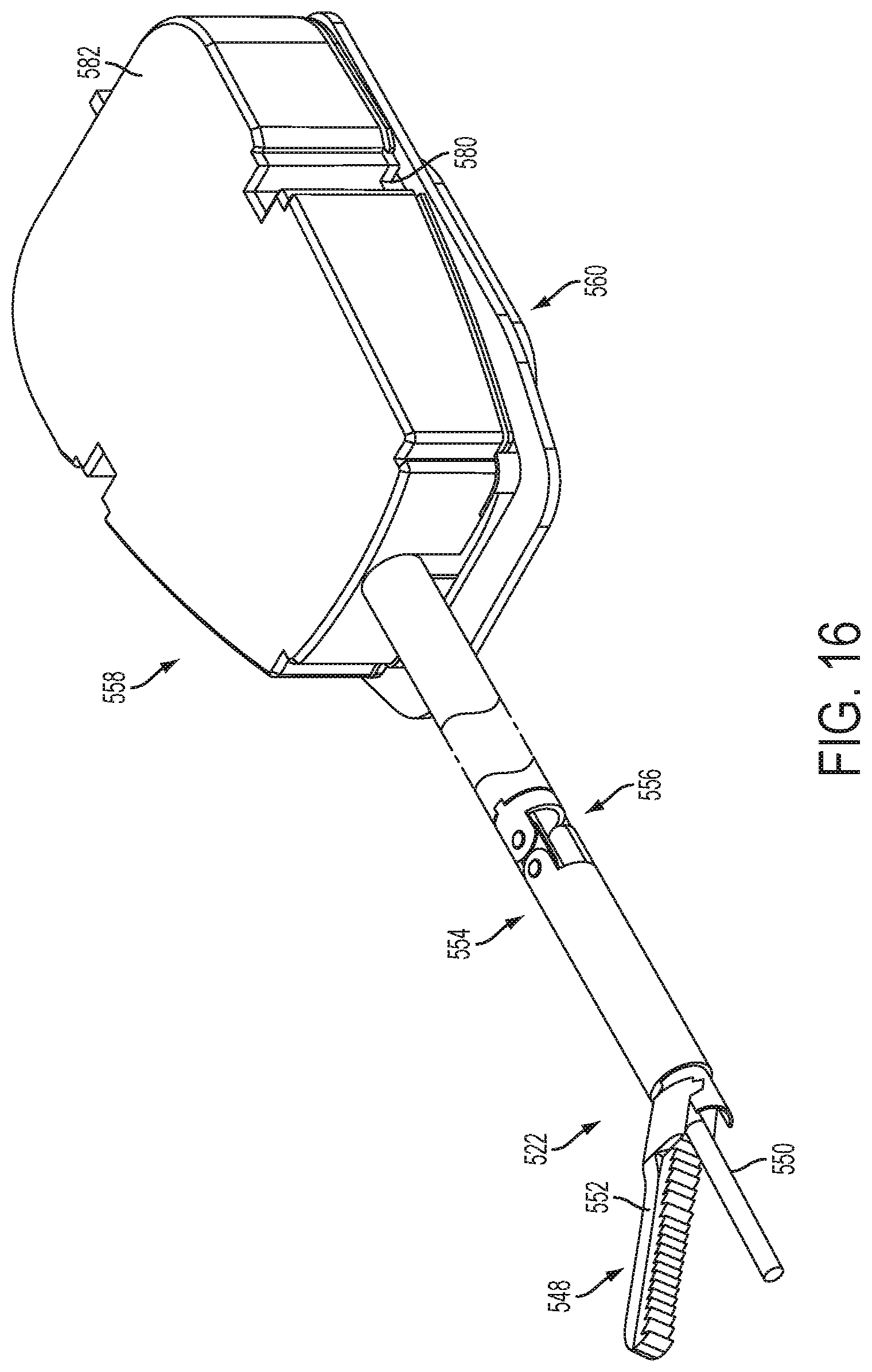
D00015

D00016

D00017

D00018

D00019

D00020

D00021

D00022

D00023
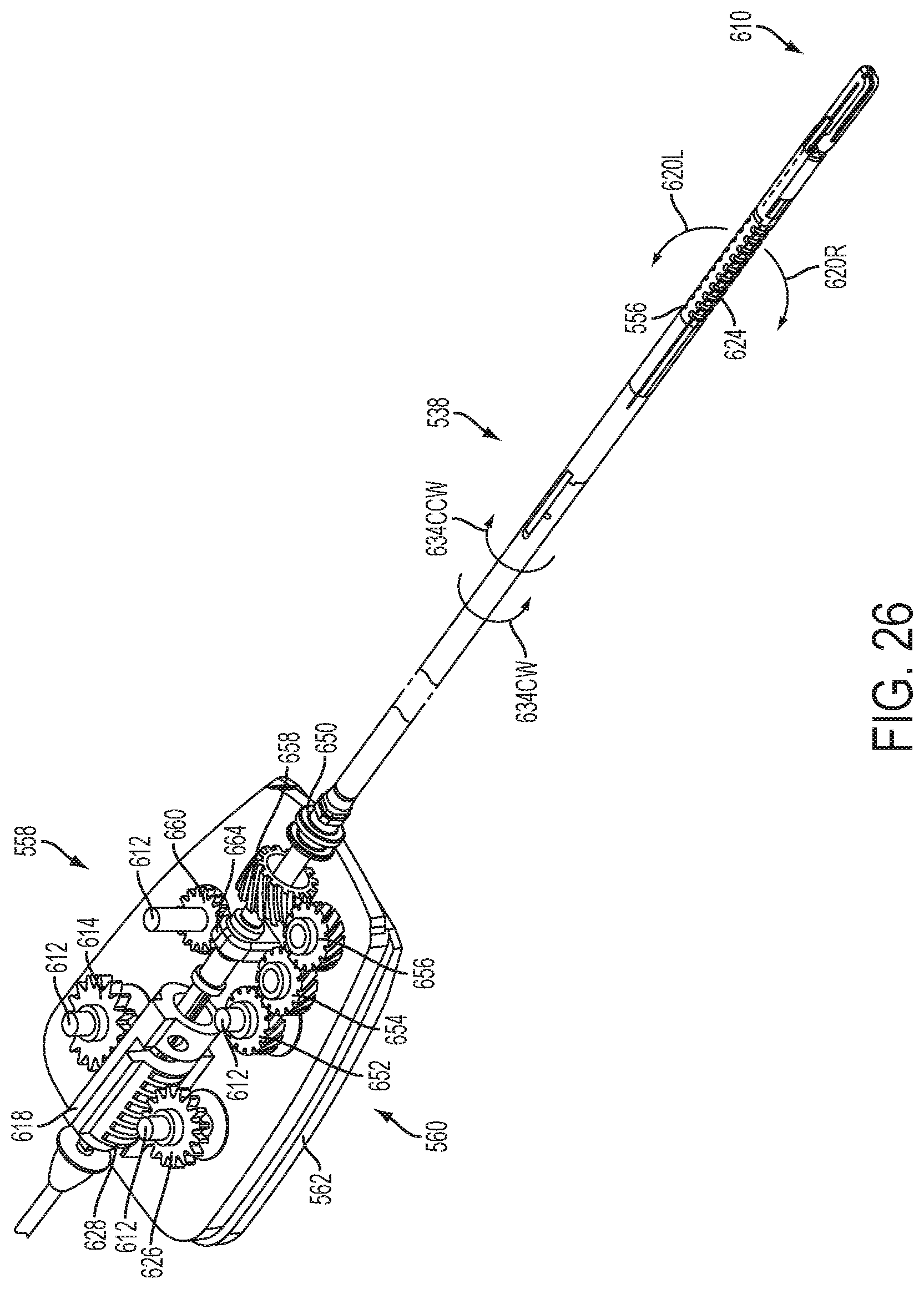
D00024
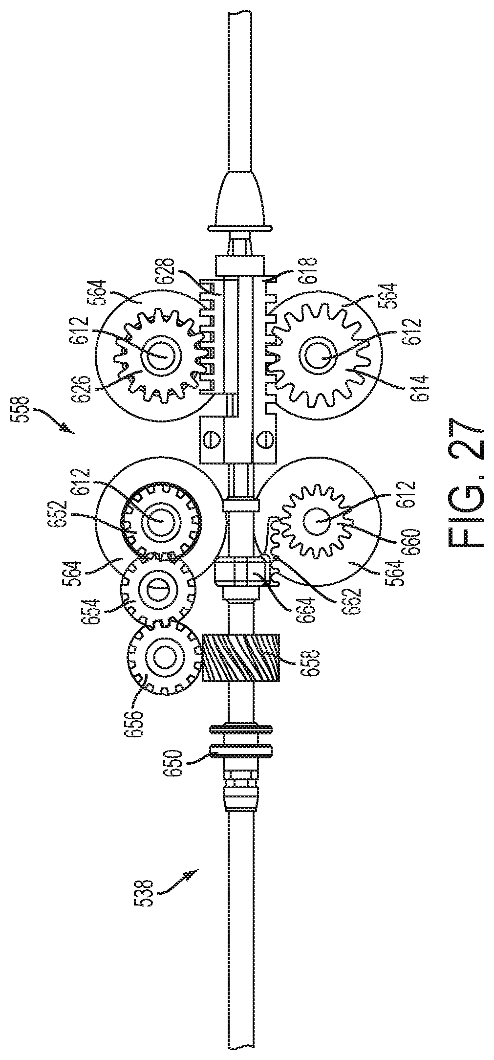
D00025

D00026

D00027

D00028

D00029

D00030

D00031

D00032

D00033
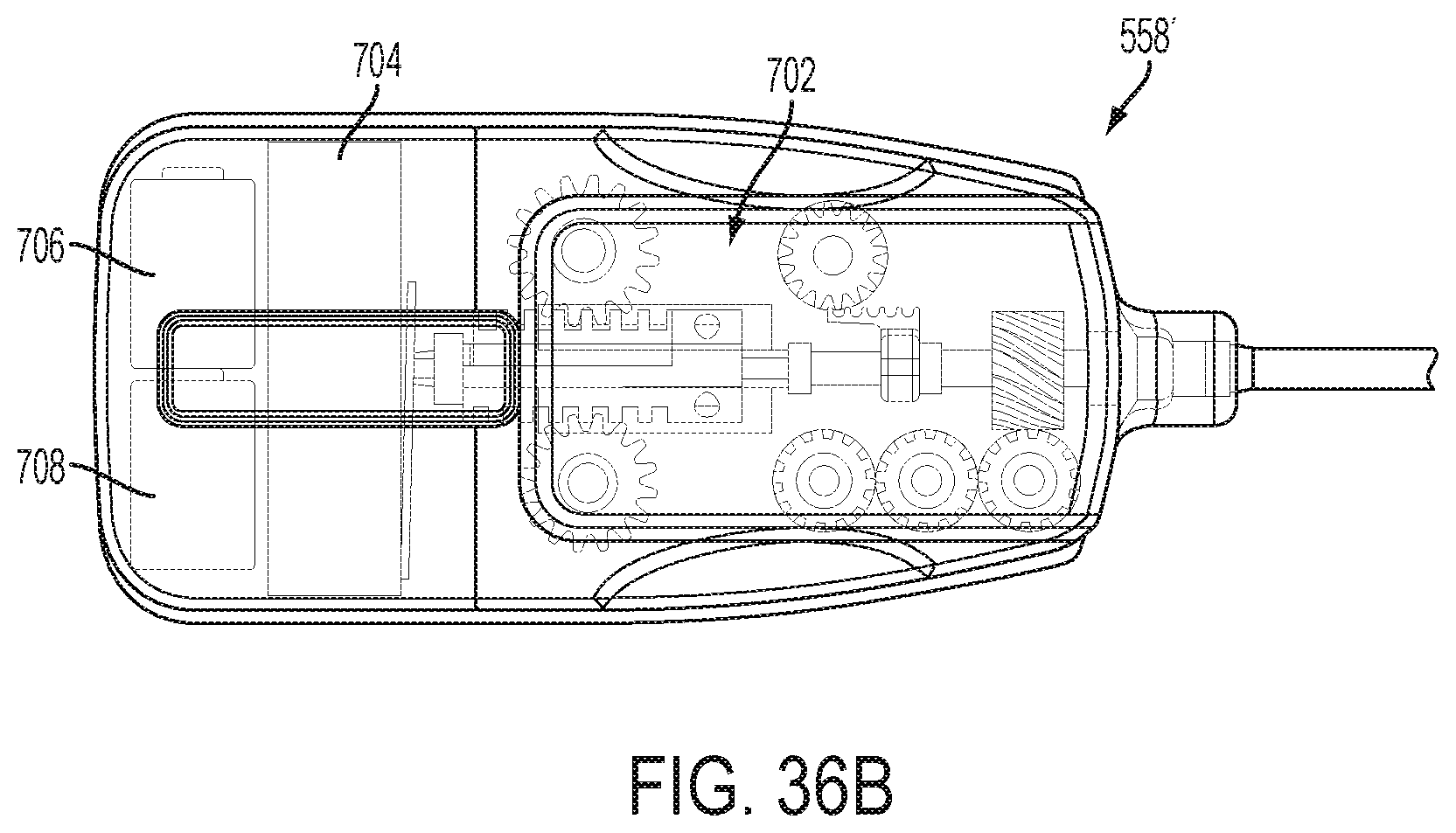
D00034
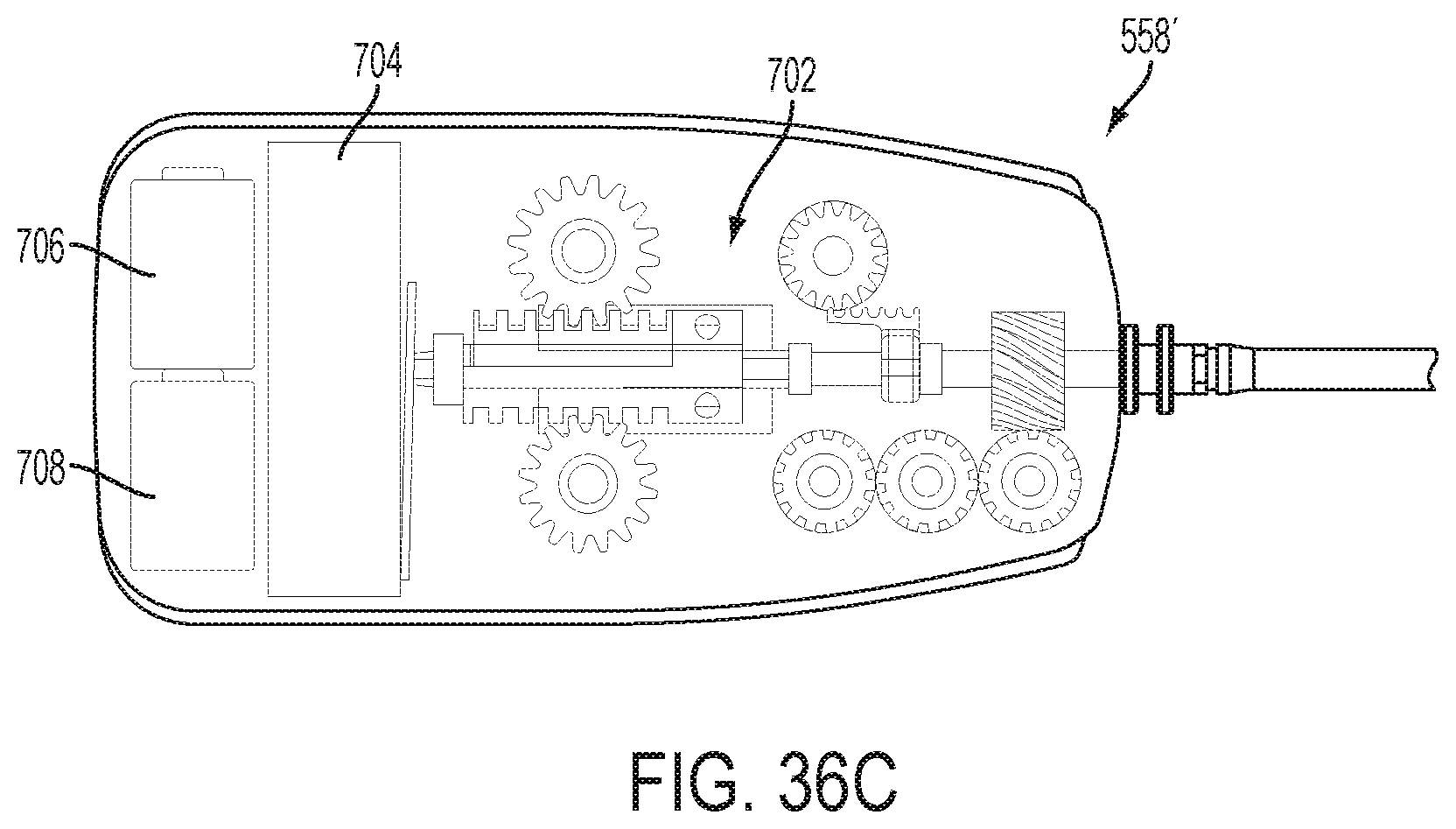
D00035

D00036

D00037

D00038

D00039
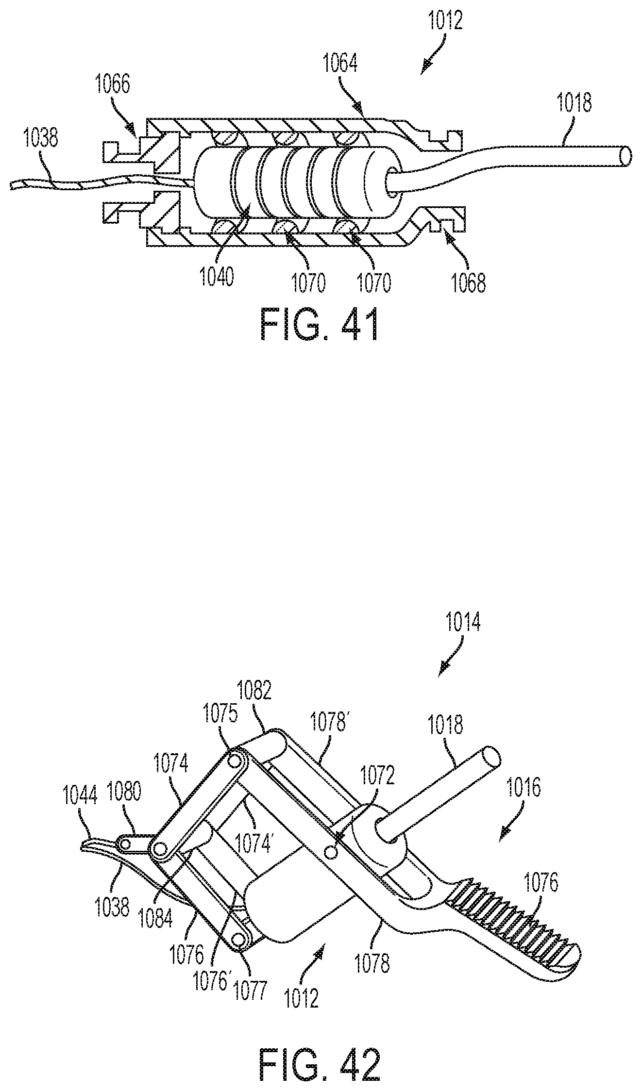
D00040

D00041

D00042

D00043

D00044

D00045

D00046
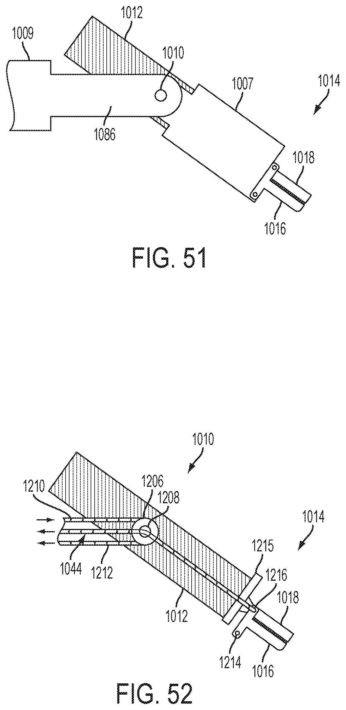
D00047

D00048

D00049

D00050

D00051
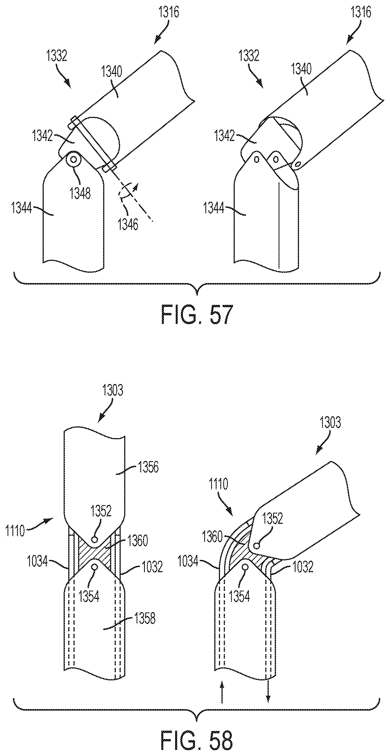
D00052

D00053

D00054

D00055

D00056

D00057

D00058

D00059

D00060
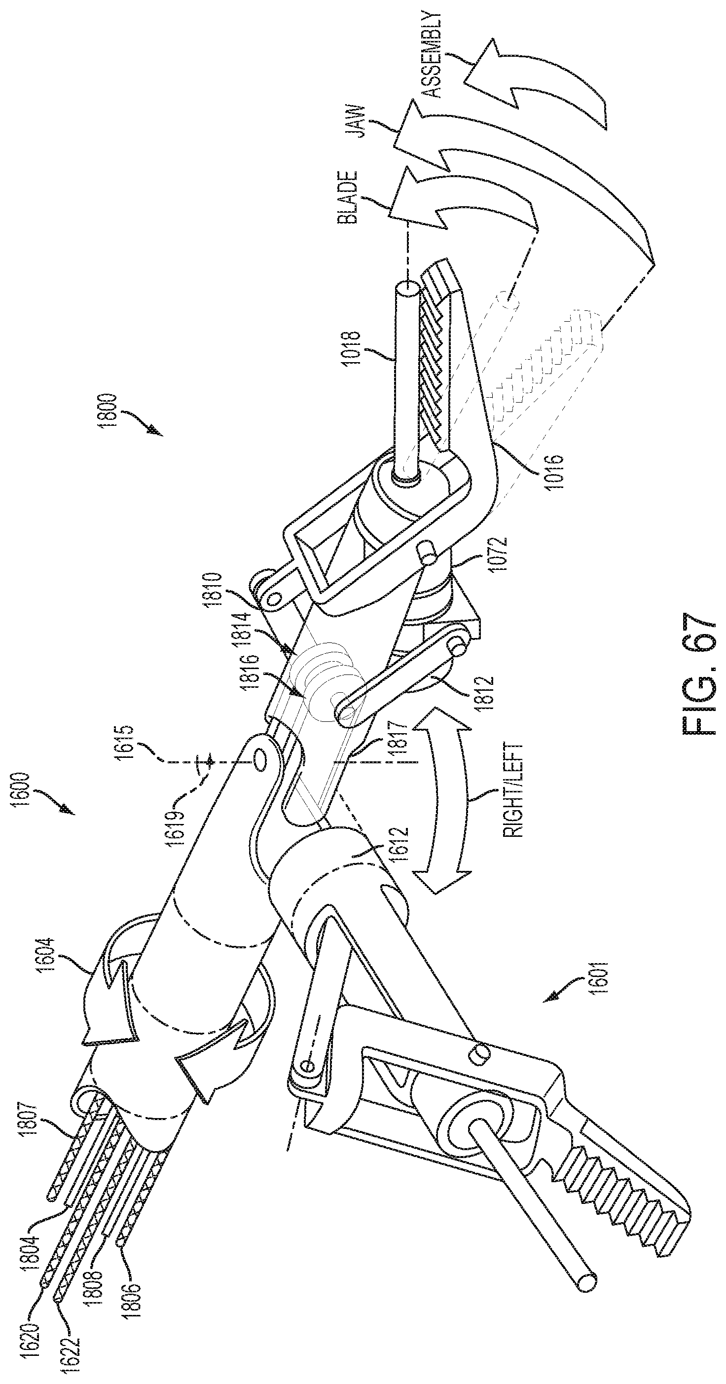
D00061

XML
uspto.report is an independent third-party trademark research tool that is not affiliated, endorsed, or sponsored by the United States Patent and Trademark Office (USPTO) or any other governmental organization. The information provided by uspto.report is based on publicly available data at the time of writing and is intended for informational purposes only.
While we strive to provide accurate and up-to-date information, we do not guarantee the accuracy, completeness, reliability, or suitability of the information displayed on this site. The use of this site is at your own risk. Any reliance you place on such information is therefore strictly at your own risk.
All official trademark data, including owner information, should be verified by visiting the official USPTO website at www.uspto.gov. This site is not intended to replace professional legal advice and should not be used as a substitute for consulting with a legal professional who is knowledgeable about trademark law.