Stepped staple cartridge with asymmetrical staples
Shelton, IV , et al. May 11, 2
U.S. patent number 11,000,276 [Application Number 16/743,262] was granted by the patent office on 2021-05-11 for stepped staple cartridge with asymmetrical staples. This patent grant is currently assigned to Ethicon LLC. The grantee listed for this patent is Ethicon LLC. Invention is credited to Gregory J. Bakos, Jason L. Harris, Frederick E. Shelton, IV.


View All Diagrams
| United States Patent | 11,000,276 |
| Shelton, IV , et al. | May 11, 2021 |
Stepped staple cartridge with asymmetrical staples
Abstract
A surgical instrument includes a staple cartridge that defines a stepped deck. The surgical instrument further includes a staple comprised of seamless unitary structure. The staple is configured to be formed and/or stamped from a sheet of material. The staple includes a base and staple legs. A staple drive surface is integrally formed in the base, and a sled is configured to directly contact the staple drive surface to directly drive the staple.
| Inventors: | Shelton, IV; Frederick E. (Hillsboro, OH), Harris; Jason L. (Lebanon, OH), Bakos; Gregory J. (Mason, OH) | ||||||||||
|---|---|---|---|---|---|---|---|---|---|---|---|
| Applicant: |
|
||||||||||
| Assignee: | Ethicon LLC (Guaynabo,
PR) |
||||||||||
| Family ID: | 1000005543177 | ||||||||||
| Appl. No.: | 16/743,262 | ||||||||||
| Filed: | January 15, 2020 |
Prior Publication Data
| Document Identifier | Publication Date | |
|---|---|---|
| US 20200222045 A1 | Jul 16, 2020 | |
Related U.S. Patent Documents
| Application Number | Filing Date | Patent Number | Issue Date | ||
|---|---|---|---|---|---|
| 15386188 | Dec 21, 2016 | 10537324 | |||
| Current U.S. Class: | 1/1 |
| Current CPC Class: | A61B 17/0644 (20130101); A61B 17/072 (20130101); A61B 17/0682 (20130101); A61B 17/064 (20130101); A61B 17/07207 (20130101); A61B 2017/0023 (20130101); A61B 2017/07257 (20130101); A61B 2017/0725 (20130101); A61B 2017/00477 (20130101); A61B 2017/07278 (20130101); A61B 2017/00526 (20130101); A61B 2017/00964 (20130101); A61B 2017/07235 (20130101); A61B 2017/07285 (20130101); A61B 2017/07228 (20130101); A61B 2017/00473 (20130101); A61B 2017/07271 (20130101); A61B 2090/038 (20160201); A61B 2017/07242 (20130101) |
| Current International Class: | A61B 17/072 (20060101); A61B 17/00 (20060101); A61B 90/00 (20160101); A61B 17/068 (20060101); A61B 17/064 (20060101) |
| Field of Search: | ;227/176 |
References Cited [Referenced By]
U.S. Patent Documents
| 66052 | June 1867 | Smith |
| 662587 | November 1900 | Blake |
| 670748 | March 1901 | Weddeler |
| 951393 | March 1910 | Hahn |
| 1306107 | June 1919 | Elliott |
| 1314601 | September 1919 | McCaskey |
| 1677337 | July 1928 | Grove |
| 1794907 | March 1931 | Kelly |
| 2037727 | April 1936 | La Chapelle |
| 2132295 | October 1938 | Hawkins |
| 2161632 | June 1939 | Nattenheimer |
| 2211117 | August 1940 | Hess |
| 2214870 | September 1940 | West |
| 2318379 | May 1943 | Davis et al. |
| 2441096 | May 1948 | Happe |
| 2475322 | July 1949 | Horton et al. |
| 2526902 | October 1950 | Rublee |
| 2578686 | December 1951 | Fish |
| 2674149 | April 1954 | Benson |
| 2711461 | June 1955 | Happe |
| 2804848 | September 1957 | O'Farrell et al. |
| 2808482 | October 1957 | Zanichkowsky et al. |
| 2853074 | September 1958 | Olson |
| 2886358 | May 1959 | Munchbach |
| 2959974 | November 1960 | Emrick |
| 3032769 | May 1962 | Palmer |
| 3060972 | October 1962 | Sheldon |
| 3075062 | January 1963 | Iaccarino |
| 3078465 | February 1963 | Bobrov |
| 3079606 | March 1963 | Bobrov et al. |
| 3166072 | January 1965 | Sullivan, Jr. |
| 3196869 | July 1965 | Scholl |
| 3204731 | September 1965 | Bent et al. |
| 3266494 | August 1966 | Brownrigg et al. |
| 3269630 | August 1966 | Fleischer |
| 3275211 | September 1966 | Hirsch et al. |
| 3317103 | May 1967 | Cullen et al. |
| 3499591 | March 1970 | Green |
| 3551987 | January 1971 | Wilkinson |
| 3583393 | June 1971 | Takahashi |
| 3662939 | May 1972 | Bryan |
| 3717294 | February 1973 | Green |
| 3799151 | March 1974 | Fukaumi et al. |
| 3940844 | March 1976 | Colby et al. |
| RE28932 | August 1976 | Noiles et al. |
| 4014244 | March 1977 | Larson |
| 4060089 | November 1977 | Noiles |
| 4106446 | August 1978 | Yamada et al. |
| 4108211 | August 1978 | Tanaka |
| 4111206 | September 1978 | Vishnevsky et al. |
| 4129059 | December 1978 | Van Eck |
| 4169990 | October 1979 | Lerdman |
| 4180285 | December 1979 | Reneau |
| 4198734 | April 1980 | Brumlik |
| 4198982 | April 1980 | Fortner et al. |
| 4207898 | June 1980 | Becht |
| 4213562 | July 1980 | Garrett et al. |
| 4226242 | October 1980 | Jarvik |
| 4241861 | December 1980 | Fleischer |
| 4244372 | January 1981 | Kapitanov et al. |
| 4250436 | February 1981 | Weissman |
| 4261244 | April 1981 | Becht et al. |
| 4272002 | June 1981 | Moshofsky |
| 4272662 | June 1981 | Simpson |
| 4274304 | June 1981 | Curtiss |
| 4275813 | June 1981 | Noiles |
| 4289133 | September 1981 | Rothfuss |
| 4296654 | October 1981 | Mercer |
| 4304236 | December 1981 | Conta et al. |
| 4305539 | December 1981 | Korolkov et al. |
| 4312685 | January 1982 | Riedl |
| 4317451 | March 1982 | Cerwin et al. |
| 4319576 | March 1982 | Rothfuss |
| 4321002 | March 1982 | Froehlich |
| 4328839 | May 1982 | Lyons et al. |
| 4331277 | May 1982 | Green |
| 4340331 | July 1982 | Savino |
| 4347450 | August 1982 | Colligan |
| 4349028 | September 1982 | Green |
| 4353371 | October 1982 | Cosman |
| 4379457 | April 1983 | Gravener et al. |
| 4380312 | April 1983 | Landrus |
| 4382326 | May 1983 | Rabuse |
| 4383634 | May 1983 | Green |
| 4393728 | July 1983 | Larson et al. |
| 4396139 | August 1983 | Hall et al. |
| 4397311 | August 1983 | Kanshin et al. |
| 4402445 | September 1983 | Green |
| 4408692 | October 1983 | Sigel et al. |
| 4409057 | October 1983 | Molenda et al. |
| 4415112 | November 1983 | Green |
| 4416276 | November 1983 | Newton et al. |
| 4428376 | January 1984 | Mericle |
| 4429695 | February 1984 | Green |
| 4434796 | March 1984 | Karapetian et al. |
| 4438659 | March 1984 | Desplats |
| 4442964 | April 1984 | Becht |
| 4448194 | May 1984 | DiGiovanni et al. |
| 4451743 | May 1984 | Suzuki et al. |
| 4454887 | June 1984 | Kruger |
| 4467805 | August 1984 | Fukuda |
| 4473077 | September 1984 | Noiles et al. |
| 4475679 | October 1984 | Fleury, Jr. |
| 4485816 | December 1984 | Krumme |
| 4486928 | December 1984 | Tucker et al. |
| 4488523 | December 1984 | Shichman |
| 4489875 | December 1984 | Crawford et al. |
| 4499895 | February 1985 | Takayama |
| 4500024 | February 1985 | DiGiovanni et al. |
| 4505272 | March 1985 | Utyamyshev et al. |
| 4505273 | March 1985 | Braun et al. |
| 4505414 | March 1985 | Filipi |
| 4506671 | March 1985 | Green |
| 4520817 | June 1985 | Green |
| 4522327 | June 1985 | Korthoff et al. |
| 4526174 | July 1985 | Froehlich |
| 4527724 | July 1985 | Chow et al. |
| 4530453 | July 1985 | Green |
| 4531522 | July 1985 | Bedi et al. |
| 4532927 | August 1985 | Miksza, Jr. |
| 4548202 | October 1985 | Duncan |
| 4565109 | January 1986 | Tsay |
| 4565189 | January 1986 | Mabuchi |
| 4566620 | January 1986 | Green et al. |
| 4569469 | February 1986 | Mongeon et al. |
| 4571213 | February 1986 | Ishimoto |
| 4573468 | March 1986 | Conta et al. |
| 4573469 | March 1986 | Golden et al. |
| 4573622 | March 1986 | Green et al. |
| 4576167 | March 1986 | Noiles |
| 4580712 | April 1986 | Green |
| 4585153 | April 1986 | Failla et al. |
| 4589416 | May 1986 | Green |
| 4591085 | May 1986 | Di Giovanni |
| 4597753 | July 1986 | Turley |
| 4600037 | July 1986 | Hatten |
| 4604786 | August 1986 | Howie, Jr. |
| 4605001 | August 1986 | Rothfuss et al. |
| 4605004 | August 1986 | Di Giovanni et al. |
| 4606343 | August 1986 | Conta et al. |
| 4607638 | August 1986 | Crainich |
| 4608981 | September 1986 | Rothfuss et al. |
| 4610250 | September 1986 | Green |
| 4610383 | September 1986 | Rothfuss et al. |
| 4612933 | September 1986 | Brinkerhoff et al. |
| D286180 | October 1986 | Korthoff |
| D286441 | October 1986 | Korthoff et al. |
| D286442 | October 1986 | Korthoff et al. |
| 4619262 | October 1986 | Taylor |
| 4619391 | October 1986 | Sharkany et al. |
| 4628459 | December 1986 | Shinohara et al. |
| 4629107 | December 1986 | Fedotov et al. |
| 4632290 | December 1986 | Green et al. |
| 4633874 | January 1987 | Chow et al. |
| 4634419 | January 1987 | Kreizman et al. |
| 4641076 | February 1987 | Linden |
| 4643731 | February 1987 | Eckenhoff |
| 4646722 | March 1987 | Silverstein et al. |
| 4652820 | March 1987 | Maresca |
| 4655222 | April 1987 | Florez et al. |
| 4662555 | May 1987 | Thornton |
| 4663874 | May 1987 | Sano et al. |
| 4664305 | May 1987 | Blake et al. |
| 4665916 | May 1987 | Green |
| 4667674 | May 1987 | Korthoff et al. |
| 4669647 | June 1987 | Storace |
| 4671445 | June 1987 | Barker et al. |
| 4676245 | June 1987 | Fukuda |
| 4684051 | August 1987 | Akopov et al. |
| 4693248 | September 1987 | Failla |
| 4700703 | October 1987 | Resnick et al. |
| 4708141 | November 1987 | Inoue et al. |
| 4709120 | November 1987 | Pearson |
| 4715520 | December 1987 | Roehr, Jr. et al. |
| 4719917 | January 1988 | Barrows et al. |
| 4727308 | February 1988 | Huljak et al. |
| 4728020 | March 1988 | Green et al. |
| 4728876 | March 1988 | Mongeon et al. |
| 4729260 | March 1988 | Dudden |
| 4730726 | March 1988 | Holzwarth |
| 4741336 | May 1988 | Failla et al. |
| 4743214 | May 1988 | Tai-Cheng |
| 4747820 | May 1988 | Hornlein et al. |
| 4750902 | June 1988 | Wuchinich et al. |
| 4752024 | June 1988 | Green et al. |
| 4754909 | July 1988 | Barker et al. |
| 4767044 | August 1988 | Green |
| D297764 | September 1988 | Hunt et al. |
| 4773420 | September 1988 | Green |
| 4777780 | October 1988 | Holzwarth |
| 4781186 | November 1988 | Simpson et al. |
| 4787387 | November 1988 | Burbank, III et al. |
| 4790225 | December 1988 | Moody et al. |
| 4802478 | February 1989 | Powell |
| 4805617 | February 1989 | Bedi et al. |
| 4805823 | February 1989 | Rothfuss |
| 4809695 | March 1989 | Gwathmey et al. |
| 4815460 | March 1989 | Porat et al. |
| 4817847 | April 1989 | Redtenbacher et al. |
| 4819853 | April 1989 | Green |
| 4821939 | April 1989 | Green |
| 4827911 | May 1989 | Broadwin et al. |
| 4830855 | May 1989 | Stewart |
| 4834720 | May 1989 | Blinkhorn |
| 4844068 | July 1989 | Arata et al. |
| 4848637 | July 1989 | Pruitt |
| 4865030 | September 1989 | Polyak |
| 4869414 | September 1989 | Green et al. |
| 4869415 | September 1989 | Fox |
| 4873977 | October 1989 | Avant et al. |
| 4874122 | October 1989 | Froelich et al. |
| 4880015 | November 1989 | Nierman |
| 4887601 | December 1989 | Richards |
| 4887756 | December 1989 | Puchy |
| 4890613 | January 1990 | Golden et al. |
| 4892244 | January 1990 | Fox et al. |
| 4893622 | January 1990 | Green et al. |
| 4894051 | January 1990 | Shiber |
| 4896678 | January 1990 | Ogawa |
| 4900303 | February 1990 | Lemelson |
| 4903697 | February 1990 | Resnick et al. |
| 4915100 | April 1990 | Green |
| 4930503 | June 1990 | Pruitt |
| 4930674 | June 1990 | Barak |
| 4931047 | June 1990 | Broadwin et al. |
| 4932960 | June 1990 | Green et al. |
| 4938408 | July 1990 | Bedi et al. |
| 4941623 | July 1990 | Pruitt |
| 4944443 | July 1990 | Oddsen et al. |
| 4951860 | August 1990 | Peters et al. |
| 4955898 | September 1990 | Matsutani et al. |
| 4955959 | September 1990 | Tompkins et al. |
| 4965709 | October 1990 | Ngo |
| 4973274 | November 1990 | Hirukawa |
| 4978049 | December 1990 | Green |
| 4978333 | December 1990 | Broadwin et al. |
| 4986808 | January 1991 | Broadwin et al. |
| 4988334 | January 1991 | Hornlein et al. |
| 5002543 | March 1991 | Bradshaw et al. |
| 5002553 | March 1991 | Shiber |
| 5005754 | April 1991 | Van Overloop |
| 5009661 | April 1991 | Michelson |
| 5014899 | May 1991 | Presty et al. |
| 5015227 | May 1991 | Broadwin et al. |
| 5018515 | May 1991 | Gilman |
| 5018657 | May 1991 | Pedlick et al. |
| 5024671 | June 1991 | Tu et al. |
| 5027834 | July 1991 | Pruitt |
| 5031814 | July 1991 | Tompkins et al. |
| 5035040 | July 1991 | Kerrigan et al. |
| 5038109 | August 1991 | Goble et al. |
| 5040715 | August 1991 | Green et al. |
| 5042707 | August 1991 | Taheri |
| 5053047 | October 1991 | Yoon |
| 5061269 | October 1991 | Muller |
| 5062563 | November 1991 | Green et al. |
| 5065929 | November 1991 | Schulze et al. |
| 5071052 | December 1991 | Rodak et al. |
| 5071430 | December 1991 | de Salis et al. |
| 5074454 | December 1991 | Peters |
| 5079006 | January 1992 | Urquhart |
| 5080556 | January 1992 | Carreno |
| 5083695 | January 1992 | Foslien et al. |
| 5084057 | January 1992 | Green et al. |
| 5088979 | February 1992 | Filipi et al. |
| 5088997 | February 1992 | Delahuerga et al. |
| 5089009 | February 1992 | Green |
| 5094247 | March 1992 | Hernandez et al. |
| 5100420 | March 1992 | Green et al. |
| 5104025 | April 1992 | Main et al. |
| 5104397 | April 1992 | Vasconcelos et al. |
| 5106008 | April 1992 | Tompkins et al. |
| 5108368 | April 1992 | Hammerslag et al. |
| 5111987 | May 1992 | Moeinzadeh et al. |
| 5116349 | May 1992 | Aranyi |
| D327323 | June 1992 | Hunt |
| 5122156 | June 1992 | Granger et al. |
| 5125876 | June 1992 | Hirota |
| 5129570 | July 1992 | Schulze et al. |
| 5137198 | August 1992 | Nobis et al. |
| 5139513 | August 1992 | Segato |
| 5141144 | August 1992 | Foslien et al. |
| 5142932 | September 1992 | Moya et al. |
| 5155941 | October 1992 | Takahashi et al. |
| 5156315 | October 1992 | Green et al. |
| 5156609 | October 1992 | Nakao et al. |
| 5156614 | October 1992 | Green et al. |
| 5158567 | October 1992 | Green |
| D330699 | November 1992 | Gill |
| 5163598 | November 1992 | Peters et al. |
| 5170925 | December 1992 | Madden et al. |
| 5171247 | December 1992 | Hughett et al. |
| 5171249 | December 1992 | Stefanchik et al. |
| 5171253 | December 1992 | Klieman |
| 5188111 | February 1993 | Yates et al. |
| 5190517 | March 1993 | Zieve et al. |
| 5190544 | March 1993 | Chapman et al. |
| 5190560 | March 1993 | Woods et al. |
| 5192288 | March 1993 | Thompson et al. |
| 5195968 | March 1993 | Lundquist et al. |
| 5197648 | March 1993 | Gingold |
| 5197649 | March 1993 | Bessler et al. |
| 5197966 | March 1993 | Sommerkamp |
| 5200280 | April 1993 | Karasa |
| 5201746 | April 1993 | Shichman |
| 5205459 | April 1993 | Brinkerhoff et al. |
| 5207697 | May 1993 | Carusillo et al. |
| 5209747 | May 1993 | Knoepfler |
| 5211649 | May 1993 | Kohler et al. |
| 5211655 | May 1993 | Hasson |
| 5217457 | June 1993 | Delahuerga et al. |
| 5217478 | June 1993 | Rexroth |
| 5219111 | June 1993 | Bilotti et al. |
| 5221036 | June 1993 | Takase |
| 5221281 | June 1993 | Klicek |
| 5222963 | June 1993 | Brinkerhoff et al. |
| 5222975 | June 1993 | Crainich |
| 5222976 | June 1993 | Yoon |
| 5223675 | June 1993 | Taft |
| D338729 | August 1993 | Sprecklemeier et al. |
| 5234447 | August 1993 | Kaster et al. |
| 5236440 | August 1993 | Hlavacek |
| 5239981 | August 1993 | Anapliotis |
| 5240163 | August 1993 | Stein et al. |
| 5242457 | September 1993 | Akopov et al. |
| 5244462 | September 1993 | Delahuerga et al. |
| 5246156 | September 1993 | Rothfuss et al. |
| 5246443 | September 1993 | Mai |
| 5253793 | October 1993 | Green et al. |
| 5258009 | November 1993 | Conners |
| 5258012 | November 1993 | Luscombe et al. |
| 5259366 | November 1993 | Reydel et al. |
| 5260637 | November 1993 | Pizzi |
| 5263629 | November 1993 | Trumbull et al. |
| 5263973 | November 1993 | Cook |
| 5264218 | November 1993 | Rogozinski |
| 5268622 | December 1993 | Philipp |
| 5271543 | December 1993 | Grant et al. |
| 5271544 | December 1993 | Fox et al. |
| RE34519 | January 1994 | Fox et al. |
| 5275323 | January 1994 | Schulze et al. |
| 5275608 | January 1994 | Forman et al. |
| 5279416 | January 1994 | Malec et al. |
| 5281216 | January 1994 | Klicek |
| 5282806 | February 1994 | Haber et al. |
| 5282829 | February 1994 | Hermes |
| 5284128 | February 1994 | Hart |
| 5285945 | February 1994 | Brinkerhoff et al. |
| 5289963 | March 1994 | McGarry et al. |
| 5290271 | March 1994 | Jernberg |
| 5292053 | March 1994 | Bilotti et al. |
| 5297714 | March 1994 | Kramer |
| 5303539 | April 1994 | Neamtu |
| 5304204 | April 1994 | Bregen |
| D347474 | May 1994 | Olson |
| 5307976 | May 1994 | Olson et al. |
| 5308576 | May 1994 | Green et al. |
| 5309927 | May 1994 | Welch |
| 5312023 | May 1994 | Green et al. |
| 5312024 | May 1994 | Grant et al. |
| 5312329 | May 1994 | Beaty et al. |
| 5314424 | May 1994 | Nicholas |
| 5314445 | May 1994 | Heidmueller nee Degwitz et al. |
| 5314466 | May 1994 | Stern et al. |
| 5318221 | June 1994 | Green et al. |
| D348930 | July 1994 | Olson |
| 5329923 | July 1994 | Lundquist |
| 5330487 | July 1994 | Thornton et al. |
| 5330502 | July 1994 | Hassler et al. |
| 5332142 | July 1994 | Robinson et al. |
| 5333422 | August 1994 | Warren et al. |
| 5333772 | August 1994 | Rothfuss et al. |
| 5333773 | August 1994 | Main et al. |
| 5334183 | August 1994 | Wuchinich |
| 5336229 | August 1994 | Noda |
| 5336232 | August 1994 | Green et al. |
| 5339799 | August 1994 | Kami et al. |
| 5341724 | August 1994 | Vatel |
| 5341810 | August 1994 | Dardel |
| 5342381 | August 1994 | Tidemand |
| 5342395 | August 1994 | Jarrett et al. |
| 5342396 | August 1994 | Cook |
| 5344060 | September 1994 | Gravener et al. |
| 5344454 | September 1994 | Clarke et al. |
| 5346504 | September 1994 | Ortiz et al. |
| 5348259 | September 1994 | Blanco et al. |
| 5350388 | September 1994 | Epstein |
| 5350391 | September 1994 | Iacovelli |
| 5350400 | September 1994 | Esposito et al. |
| 5352229 | October 1994 | Goble et al. |
| 5352235 | October 1994 | Koros et al. |
| 5352238 | October 1994 | Green et al. |
| 5354303 | October 1994 | Spaeth et al. |
| 5356006 | October 1994 | Alpern et al. |
| 5358506 | October 1994 | Green et al. |
| 5358510 | October 1994 | Luscombe et al. |
| 5359231 | October 1994 | Flowers et al. |
| D352780 | November 1994 | Glaeser et al. |
| 5360305 | November 1994 | Kerrigan |
| 5360428 | November 1994 | Hutchinson, Jr. |
| 5364001 | November 1994 | Bryan |
| 5364003 | November 1994 | Williamson, IV |
| 5366133 | November 1994 | Geiste |
| 5366134 | November 1994 | Green et al. |
| 5366479 | November 1994 | McGarry et al. |
| 5368015 | November 1994 | Wilk |
| 5368592 | November 1994 | Stern et al. |
| 5370645 | December 1994 | Klicek et al. |
| 5372124 | December 1994 | Takayama et al. |
| 5372596 | December 1994 | Klicek et al. |
| 5372602 | December 1994 | Burke |
| 5374277 | December 1994 | Hassler |
| 5376095 | December 1994 | Ortiz |
| 5379933 | January 1995 | Green et al. |
| 5381649 | January 1995 | Webb |
| 5381782 | January 1995 | DeLaRama et al. |
| 5381943 | January 1995 | Allen et al. |
| 5382247 | January 1995 | Cimino et al. |
| 5383880 | January 1995 | Hooven |
| 5383881 | January 1995 | Green et al. |
| 5383882 | January 1995 | Buess et al. |
| 5383888 | January 1995 | Zvenyatsky et al. |
| 5383895 | January 1995 | Holmes et al. |
| 5389098 | February 1995 | Tsuruta et al. |
| 5389104 | February 1995 | Hahnen et al. |
| 5391180 | February 1995 | Tovey et al. |
| 5392978 | February 1995 | Velez et al. |
| 5392979 | February 1995 | Green et al. |
| 5395030 | March 1995 | Kuramoto et al. |
| 5395033 | March 1995 | Byrne et al. |
| 5395034 | March 1995 | Allen et al. |
| 5395312 | March 1995 | Desai |
| 5395384 | March 1995 | Duthoit et al. |
| 5397046 | March 1995 | Savage et al. |
| 5397324 | March 1995 | Carroll et al. |
| 5403043 | April 1995 | Smet |
| 5403312 | April 1995 | Yates et al. |
| 5405072 | April 1995 | Zlock et al. |
| 5405073 | April 1995 | Porter |
| 5405344 | April 1995 | Williamson et al. |
| 5405360 | April 1995 | Tovey |
| 5407293 | April 1995 | Crainich |
| 5409498 | April 1995 | Braddock et al. |
| D357981 | May 1995 | Green et al. |
| 5411481 | May 1995 | Allen et al. |
| 5411508 | May 1995 | Bessler et al. |
| 5413107 | May 1995 | Oakley et al. |
| 5413267 | May 1995 | Solyntjes et al. |
| 5413268 | May 1995 | Green et al. |
| 5413272 | May 1995 | Green et al. |
| 5413573 | May 1995 | Koivukangas |
| 5415334 | May 1995 | Williamson et al. |
| 5415335 | May 1995 | Knodell, Jr. |
| 5417203 | May 1995 | Tovey et al. |
| 5417361 | May 1995 | Williamson, IV |
| 5421829 | June 1995 | Olichney et al. |
| 5422567 | June 1995 | Matsunaga |
| 5423471 | June 1995 | Mastri et al. |
| 5423809 | June 1995 | Klicek |
| 5425745 | June 1995 | Green et al. |
| 5431322 | July 1995 | Green et al. |
| 5431654 | July 1995 | Nic |
| 5431668 | July 1995 | Burbank, III et al. |
| 5433721 | July 1995 | Hooven et al. |
| 5437681 | August 1995 | Meade et al. |
| 5438302 | August 1995 | Goble |
| 5439155 | August 1995 | Viola |
| 5439156 | August 1995 | Grant et al. |
| 5439479 | August 1995 | Shichman et al. |
| 5441191 | August 1995 | Linden |
| 5441193 | August 1995 | Gravener |
| 5441483 | August 1995 | Avitall |
| 5441494 | August 1995 | Ortiz |
| 5444113 | August 1995 | Sinclair et al. |
| 5445155 | August 1995 | Sieben |
| 5445304 | August 1995 | Plyley et al. |
| 5445644 | August 1995 | Pietrafitta et al. |
| 5447265 | September 1995 | Vidal et al. |
| 5447417 | September 1995 | Kuhl et al. |
| 5447513 | September 1995 | Davison et al. |
| 5449355 | September 1995 | Rhum et al. |
| 5449365 | September 1995 | Green et al. |
| 5449370 | September 1995 | Vaitekunas |
| 5452836 | September 1995 | Huitema et al. |
| 5452837 | September 1995 | Williamson, IV et al. |
| 5454378 | October 1995 | Palmer et al. |
| 5454822 | October 1995 | Schob et al. |
| 5454827 | October 1995 | Aust et al. |
| 5456401 | October 1995 | Green et al. |
| 5458579 | October 1995 | Chodorow et al. |
| 5462215 | October 1995 | Viola et al. |
| 5464013 | November 1995 | Lemelson |
| 5464144 | November 1995 | Guy et al. |
| 5464300 | November 1995 | Crainich |
| 5465819 | November 1995 | Weilant et al. |
| 5465894 | November 1995 | Clark et al. |
| 5465895 | November 1995 | Knodel et al. |
| 5465896 | November 1995 | Allen et al. |
| 5466020 | November 1995 | Page et al. |
| 5467911 | November 1995 | Tsuruta et al. |
| 5468253 | November 1995 | Bezwada et al. |
| 5470006 | November 1995 | Rodak |
| 5470007 | November 1995 | Plyley et al. |
| 5470009 | November 1995 | Rodak |
| 5470010 | November 1995 | Rothfuss et al. |
| 5472132 | December 1995 | Savage et al. |
| 5472442 | December 1995 | Klicek |
| 5473204 | December 1995 | Temple |
| 5474057 | December 1995 | Makower et al. |
| 5474223 | December 1995 | Viola et al. |
| 5474566 | December 1995 | Alesi et al. |
| 5476206 | December 1995 | Green et al. |
| 5476479 | December 1995 | Green et al. |
| 5478003 | December 1995 | Green et al. |
| 5478354 | December 1995 | Tovey et al. |
| 5480089 | January 1996 | Blewett |
| 5480409 | January 1996 | Riza |
| 5482197 | January 1996 | Green et al. |
| 5484095 | January 1996 | Green et al. |
| 5484398 | January 1996 | Stoddard |
| 5484451 | January 1996 | Akopov et al. |
| 5485947 | January 1996 | Olson et al. |
| 5485952 | January 1996 | Fontayne |
| 5487499 | January 1996 | Sorrentino et al. |
| 5487500 | January 1996 | Knodel et al. |
| 5489058 | February 1996 | Plyley et al. |
| 5489256 | February 1996 | Adair |
| 5496312 | March 1996 | Klicek |
| 5496317 | March 1996 | Goble et al. |
| 5497933 | March 1996 | DeFonzo et al. |
| 5501654 | March 1996 | Failla et al. |
| 5503320 | April 1996 | Webster et al. |
| 5503635 | April 1996 | Sauer et al. |
| 5503638 | April 1996 | Cooper et al. |
| 5505363 | April 1996 | Green et al. |
| 5507425 | April 1996 | Ziglioli |
| 5507426 | April 1996 | Young et al. |
| 5509596 | April 1996 | Green et al. |
| 5509916 | April 1996 | Taylor |
| 5511564 | April 1996 | Wilk |
| 5514129 | May 1996 | Smith |
| 5514157 | May 1996 | Nicholas et al. |
| 5518163 | May 1996 | Hooven |
| 5518164 | May 1996 | Hooven |
| 5520678 | May 1996 | Heckele et al. |
| 5520700 | May 1996 | Beyar et al. |
| 5522817 | June 1996 | Sander et al. |
| 5522831 | June 1996 | Sleister et al. |
| 5527320 | June 1996 | Carruthers et al. |
| 5529235 | June 1996 | Boiarski et al. |
| D372086 | July 1996 | Grasso et al. |
| 5531305 | July 1996 | Roberts et al. |
| 5531744 | July 1996 | Nardella et al. |
| 5533521 | July 1996 | Granger |
| 5533581 | July 1996 | Barth et al. |
| 5533661 | July 1996 | Main et al. |
| 5535934 | July 1996 | Boiarski et al. |
| 5535935 | July 1996 | Vidal et al. |
| 5535937 | July 1996 | Boiarski et al. |
| 5540375 | July 1996 | Bolanos et al. |
| 5541376 | July 1996 | Ladtkow et al. |
| 5542594 | August 1996 | McKean et al. |
| 5542949 | August 1996 | Yoon |
| 5543119 | August 1996 | Sutter et al. |
| 5547117 | August 1996 | Hamblin et al. |
| 5549621 | August 1996 | Bessler et al. |
| 5549627 | August 1996 | Kieturakis |
| 5549628 | August 1996 | Cooper et al. |
| 5549637 | August 1996 | Crainich |
| 5551622 | September 1996 | Yoon |
| 5553675 | September 1996 | Pitzen et al. |
| 5553765 | September 1996 | Knodel et al. |
| 5554148 | September 1996 | Aebischer et al. |
| 5554169 | September 1996 | Green et al. |
| 5556416 | September 1996 | Clark et al. |
| 5558665 | September 1996 | Kieturakis |
| 5558671 | September 1996 | Yates |
| 5560530 | October 1996 | Bolanos et al. |
| 5560532 | October 1996 | DeFonzo et al. |
| 5562239 | October 1996 | Boiarski et al. |
| 5562241 | October 1996 | Knodel et al. |
| 5562682 | October 1996 | Oberlin et al. |
| 5562690 | October 1996 | Green et al. |
| 5562701 | October 1996 | Huitema et al. |
| 5562702 | October 1996 | Huitema et al. |
| 5564615 | October 1996 | Bishop et al. |
| 5569161 | October 1996 | Ebling et al. |
| 5569270 | October 1996 | Weng |
| 5569284 | October 1996 | Young et al. |
| 5571090 | November 1996 | Sherts |
| 5571100 | November 1996 | Goble et al. |
| 5571116 | November 1996 | Bolanos et al. |
| 5571285 | November 1996 | Chow et al. |
| 5573541 | November 1996 | Green et al. |
| 5573543 | November 1996 | Akopov et al. |
| 5574431 | November 1996 | McKeown et al. |
| 5575054 | November 1996 | Klinzing et al. |
| 5575789 | November 1996 | Bell et al. |
| 5575799 | November 1996 | Bolanos et al. |
| 5575803 | November 1996 | Cooper et al. |
| 5575805 | November 1996 | Li |
| 5577654 | November 1996 | Bishop |
| 5579978 | December 1996 | Green et al. |
| 5580067 | December 1996 | Hamblin et al. |
| 5582611 | December 1996 | Tsuruta et al. |
| 5582617 | December 1996 | Klieman et al. |
| 5584425 | December 1996 | Savage et al. |
| 5586711 | December 1996 | Plyley et al. |
| 5588579 | December 1996 | Schnut et al. |
| 5588580 | December 1996 | Paul et al. |
| 5588581 | December 1996 | Conlon et al. |
| 5591170 | January 1997 | Spievack et al. |
| 5591187 | January 1997 | Dekel |
| 5597107 | January 1997 | Knodel et al. |
| 5599151 | February 1997 | Daum et al. |
| 5599279 | February 1997 | Slotman et al. |
| 5599344 | February 1997 | Paterson |
| 5599350 | February 1997 | Schulze et al. |
| 5599852 | February 1997 | Scopelianos et al. |
| 5601224 | February 1997 | Bishop et al. |
| 5603443 | February 1997 | Clark et al. |
| 5605272 | February 1997 | Witt et al. |
| 5605273 | February 1997 | Hamblin et al. |
| 5607094 | March 1997 | Clark et al. |
| 5607095 | March 1997 | Smith et al. |
| 5607433 | March 1997 | Polla et al. |
| 5607450 | March 1997 | Zvenyatsky et al. |
| 5609285 | March 1997 | Grant et al. |
| 5609601 | March 1997 | Kolesa et al. |
| 5611709 | March 1997 | McAnulty |
| 5613966 | March 1997 | Makower et al. |
| 5615820 | April 1997 | Viola |
| 5618294 | April 1997 | Aust et al. |
| 5618303 | April 1997 | Marlow et al. |
| 5618307 | April 1997 | Donlon et al. |
| 5619992 | April 1997 | Guthrie et al. |
| 5620289 | April 1997 | Curry |
| 5620452 | April 1997 | Yoon |
| 5624398 | April 1997 | Smith et al. |
| 5624452 | April 1997 | Yates |
| 5626587 | May 1997 | Bishop et al. |
| 5626595 | May 1997 | Sklar et al. |
| 5628446 | May 1997 | Geiste et al. |
| 5628743 | May 1997 | Cimino |
| 5628745 | May 1997 | Bek |
| 5630539 | May 1997 | Plyley et al. |
| 5630540 | May 1997 | Blewett |
| 5630541 | May 1997 | Williamson, IV et al. |
| 5630782 | May 1997 | Adair |
| 5632432 | May 1997 | Schulze et al. |
| 5632433 | May 1997 | Grant et al. |
| 5634584 | June 1997 | Okorocha et al. |
| 5636779 | June 1997 | Palmer |
| 5636780 | June 1997 | Green et al. |
| 5639008 | June 1997 | Gallagher et al. |
| D381077 | July 1997 | Hunt |
| 5643291 | July 1997 | Pier et al. |
| 5645209 | July 1997 | Green et al. |
| 5647526 | July 1997 | Green et al. |
| 5647869 | July 1997 | Goble et al. |
| 5649937 | July 1997 | Bito et al. |
| 5649956 | July 1997 | Jensen et al. |
| 5651491 | July 1997 | Heaton et al. |
| 5653373 | August 1997 | Green et al. |
| 5653374 | August 1997 | Young et al. |
| 5653677 | August 1997 | Okada et al. |
| 5653721 | August 1997 | Knodel et al. |
| 5655698 | August 1997 | Yoon |
| 5657921 | August 1997 | Young et al. |
| 5658238 | August 1997 | Suzuki et al. |
| 5658281 | August 1997 | Heard |
| 5658300 | August 1997 | Bito et al. |
| 5658307 | August 1997 | Exconde |
| 5662258 | September 1997 | Knodel et al. |
| 5662260 | September 1997 | Yoon |
| 5662662 | September 1997 | Bishop et al. |
| 5665085 | September 1997 | Nardella |
| 5665100 | September 1997 | Yoon |
| 5667517 | September 1997 | Hooven |
| 5667526 | September 1997 | Levin |
| 5667527 | September 1997 | Cook |
| 5669544 | September 1997 | Schulze et al. |
| 5669904 | September 1997 | Platt, Jr. et al. |
| 5669907 | September 1997 | Platt, Jr. et al. |
| 5669918 | September 1997 | Balazs et al. |
| 5673840 | October 1997 | Schulze et al. |
| 5673841 | October 1997 | Schulze et al. |
| 5673842 | October 1997 | Bittner et al. |
| 5674286 | October 1997 | D'Alessio et al. |
| 5678748 | October 1997 | Plyley et al. |
| 5680981 | October 1997 | Mililli et al. |
| 5680982 | October 1997 | Schulze et al. |
| 5680983 | October 1997 | Plyley et al. |
| 5683349 | November 1997 | Makower et al. |
| 5685474 | November 1997 | Seeber |
| 5686090 | November 1997 | Schilder et al. |
| 5688270 | November 1997 | Yates et al. |
| 5690269 | November 1997 | Bolanos et al. |
| 5692668 | December 1997 | Schulze et al. |
| 5693020 | December 1997 | Rauh |
| 5693042 | December 1997 | Boiarski et al. |
| 5693051 | December 1997 | Schulze et al. |
| 5695494 | December 1997 | Becker |
| 5695502 | December 1997 | Pier et al. |
| 5695504 | December 1997 | Gifford, III et al. |
| 5695524 | December 1997 | Kelley et al. |
| 5697542 | December 1997 | Knodel et al. |
| 5697543 | December 1997 | Burdorff |
| 5697909 | December 1997 | Eggers et al. |
| 5697943 | December 1997 | Sauer et al. |
| 5700270 | December 1997 | Peyser et al. |
| 5702387 | December 1997 | Arts et al. |
| 5702408 | December 1997 | Wales et al. |
| 5702409 | December 1997 | Rayburn et al. |
| 5704087 | January 1998 | Strub |
| 5704534 | January 1998 | Huitema et al. |
| 5706997 | January 1998 | Green et al. |
| 5706998 | January 1998 | Plyley et al. |
| 5707392 | January 1998 | Kortenbach |
| 5709334 | January 1998 | Sorrentino et al. |
| 5709335 | January 1998 | Heck |
| 5709680 | January 1998 | Yates et al. |
| 5709706 | January 1998 | Kienzle et al. |
| 5711472 | January 1998 | Bryan |
| 5713128 | February 1998 | Schrenk et al. |
| 5713505 | February 1998 | Huitema |
| 5713895 | February 1998 | Lontine et al. |
| 5713896 | February 1998 | Nardella |
| 5713920 | February 1998 | Bezwada et al. |
| 5715604 | February 1998 | Lanzoni |
| 5715987 | February 1998 | Kelley et al. |
| 5715988 | February 1998 | Palmer |
| 5716366 | February 1998 | Yates |
| 5718359 | February 1998 | Palmer et al. |
| 5718360 | February 1998 | Green et al. |
| 5718548 | February 1998 | Cotellessa |
| 5718706 | February 1998 | Roger |
| 5720744 | February 1998 | Eggleston et al. |
| D393067 | March 1998 | Geary et al. |
| 5725536 | March 1998 | Oberlin et al. |
| 5725554 | March 1998 | Simon et al. |
| 5728110 | March 1998 | Vidal et al. |
| 5728121 | March 1998 | Bimbo et al. |
| 5730758 | March 1998 | Allgeyer |
| 5732821 | March 1998 | Stone et al. |
| 5732871 | March 1998 | Clark et al. |
| 5732872 | March 1998 | Bolduc et al. |
| 5733308 | March 1998 | Daugherty et al. |
| 5735445 | April 1998 | Vidal et al. |
| 5735848 | April 1998 | Yates et al. |
| 5735874 | April 1998 | Measamer et al. |
| 5738474 | April 1998 | Blewett |
| 5738648 | April 1998 | Lands et al. |
| 5743456 | April 1998 | Jones et al. |
| 5747953 | May 1998 | Philipp |
| 5749889 | May 1998 | Bacich et al. |
| 5749893 | May 1998 | Vidal et al. |
| 5752644 | May 1998 | Bolanos et al. |
| 5752965 | May 1998 | Francis et al. |
| 5755717 | May 1998 | Yates et al. |
| 5758814 | June 1998 | Gallagher et al. |
| 5762255 | June 1998 | Chrisman et al. |
| 5762256 | June 1998 | Mastri et al. |
| 5766188 | June 1998 | Igaki |
| 5766205 | June 1998 | Zvenyatsky et al. |
| 5769892 | June 1998 | Kingwell |
| 5772379 | June 1998 | Evensen |
| 5772578 | June 1998 | Heimberger et al. |
| 5772659 | June 1998 | Becker et al. |
| 5776130 | July 1998 | Buysse et al. |
| 5778939 | July 1998 | Hok-Yin |
| 5779130 | July 1998 | Alesi et al. |
| 5779131 | July 1998 | Knodel et al. |
| 5779132 | July 1998 | Knodel et al. |
| 5782396 | July 1998 | Mastri et al. |
| 5782397 | July 1998 | Koukline |
| 5782748 | July 1998 | Palmer et al. |
| 5782749 | July 1998 | Riza |
| 5782859 | July 1998 | Nicholas et al. |
| 5784934 | July 1998 | Izumisawa |
| 5785232 | July 1998 | Vidal et al. |
| 5785647 | July 1998 | Tompkins et al. |
| 5787897 | August 1998 | Kieturakis |
| 5792135 | August 1998 | Madhani et al. |
| 5792165 | August 1998 | Klieman et al. |
| 5794834 | August 1998 | Hamblin et al. |
| 5796188 | August 1998 | Bays |
| 5797536 | August 1998 | Smith et al. |
| 5797537 | August 1998 | Oberlin et al. |
| 5797538 | August 1998 | Heaton et al. |
| 5797906 | August 1998 | Rhum et al. |
| 5797958 | August 1998 | Yoon |
| 5797959 | August 1998 | Castro et al. |
| 5799857 | September 1998 | Robertson et al. |
| 5800379 | September 1998 | Edwards |
| 5800423 | September 1998 | Jensen |
| 5806676 | September 1998 | Wasgien |
| 5807376 | September 1998 | Viola et al. |
| 5807378 | September 1998 | Jensen et al. |
| 5807393 | September 1998 | Williamson, IV et al. |
| 5809441 | September 1998 | McKee |
| 5810721 | September 1998 | Mueller et al. |
| 5810811 | September 1998 | Yates et al. |
| 5810846 | September 1998 | Virnich et al. |
| 5810855 | September 1998 | Rayburn et al. |
| 5813813 | September 1998 | Daum et al. |
| 5814055 | September 1998 | Knodel et al. |
| 5814057 | September 1998 | Oi et al. |
| 5816471 | October 1998 | Plyley et al. |
| 5817084 | October 1998 | Jensen |
| 5817091 | October 1998 | Nardella et al. |
| 5817093 | October 1998 | Williamson, IV et al. |
| 5817109 | October 1998 | McGarry et al. |
| 5817119 | October 1998 | Klieman et al. |
| 5820009 | October 1998 | Melling et al. |
| 5823066 | October 1998 | Huitema et al. |
| 5826776 | October 1998 | Schulze et al. |
| 5827271 | October 1998 | Buysse et al. |
| 5827298 | October 1998 | Hart et al. |
| 5829662 | November 1998 | Allen et al. |
| 5830598 | November 1998 | Patterson |
| 5833690 | November 1998 | Yates et al. |
| 5833695 | November 1998 | Yoon |
| 5833696 | November 1998 | Whitfield et al. |
| 5836503 | November 1998 | Ehrenfels et al. |
| 5836960 | November 1998 | Kolesa et al. |
| 5839639 | November 1998 | Sauer et al. |
| 5843021 | December 1998 | Edwards et al. |
| 5843096 | December 1998 | Igaki et al. |
| 5843097 | December 1998 | Mayenberger et al. |
| 5843122 | December 1998 | Riza |
| 5843132 | December 1998 | Ilvento |
| 5843169 | December 1998 | Taheri |
| 5846254 | December 1998 | Schulze et al. |
| 5849011 | December 1998 | Jones et al. |
| 5849023 | December 1998 | Mericle |
| 5855311 | January 1999 | Hamblin et al. |
| 5855583 | January 1999 | Wang et al. |
| 5860581 | January 1999 | Robertson et al. |
| 5860975 | January 1999 | Goble et al. |
| 5865361 | February 1999 | Milliman et al. |
| 5868760 | February 1999 | McGuckin, Jr. |
| 5868790 | February 1999 | Vincent et al. |
| 5871135 | February 1999 | Williamson, IV et al. |
| 5873885 | February 1999 | Weidenbenner |
| 5876401 | March 1999 | Schulze et al. |
| 5878193 | March 1999 | Wang et al. |
| 5878937 | March 1999 | Green et al. |
| 5878938 | March 1999 | Bittner et al. |
| 5891160 | April 1999 | Williamson, IV et al. |
| 5893506 | April 1999 | Powell |
| 5893835 | April 1999 | Witt et al. |
| 5893863 | April 1999 | Yoon |
| 5893878 | April 1999 | Pierce |
| 5894979 | April 1999 | Powell |
| 5897552 | April 1999 | Edwards et al. |
| 5897562 | April 1999 | Bolanos et al. |
| 5899914 | May 1999 | Zirps et al. |
| 5901895 | May 1999 | Heaton et al. |
| 5902312 | May 1999 | Frater et al. |
| 5904647 | May 1999 | Ouchi |
| 5904693 | May 1999 | Dicesare et al. |
| 5904702 | May 1999 | Ek et al. |
| 5906625 | May 1999 | Bito et al. |
| 5908402 | June 1999 | Blythe |
| 5908427 | June 1999 | McKean et al. |
| 5911353 | June 1999 | Bolanos et al. |
| 5915616 | June 1999 | Viola et al. |
| 5916225 | June 1999 | Kugel |
| 5918791 | July 1999 | Sorrentino et al. |
| 5919198 | July 1999 | Graves, Jr. et al. |
| 5919202 | July 1999 | Yoon |
| 5921956 | July 1999 | Grinberg et al. |
| 5928256 | July 1999 | Riza |
| 5931847 | August 1999 | Bittner et al. |
| 5931853 | August 1999 | McEwen et al. |
| 5937951 | August 1999 | Izuchukwu et al. |
| 5938667 | August 1999 | Peyser et al. |
| 5941442 | August 1999 | Geiste et al. |
| 5941890 | August 1999 | Voegele et al. |
| 5944172 | August 1999 | Hannula |
| 5944715 | August 1999 | Goble et al. |
| 5947984 | September 1999 | Whipple |
| 5947996 | September 1999 | Logeman |
| 5948030 | September 1999 | Miller et al. |
| 5951516 | September 1999 | Bunyan |
| 5951552 | September 1999 | Long et al. |
| 5951574 | September 1999 | Stefanchik et al. |
| 5951581 | September 1999 | Saadat et al. |
| 5954259 | September 1999 | Viola et al. |
| 5964394 | October 1999 | Robertson |
| 5964774 | October 1999 | McKean et al. |
| 5971916 | October 1999 | Koren |
| 5973221 | October 1999 | Collyer et al. |
| D416089 | November 1999 | Barton et al. |
| 5984949 | November 1999 | Levin |
| 5988479 | November 1999 | Palmer |
| 5997528 | December 1999 | Bisch et al. |
| 5997552 | December 1999 | Person et al. |
| 6003517 | December 1999 | Sheffield et al. |
| 6004319 | December 1999 | Goble et al. |
| 6004335 | December 1999 | Vaitekunas et al. |
| 6010054 | January 2000 | Johnson et al. |
| 6010513 | January 2000 | Tormala et al. |
| 6012494 | January 2000 | Balazs |
| 6013076 | January 2000 | Goble et al. |
| 6015406 | January 2000 | Goble et al. |
| 6015417 | January 2000 | Reynolds, Jr. |
| 6017322 | January 2000 | Snoke et al. |
| 6017354 | January 2000 | Culp et al. |
| 6017356 | January 2000 | Frederick et al. |
| 6022352 | February 2000 | Vandewalle |
| 6024741 | February 2000 | Williamson, IV et al. |
| 6024748 | February 2000 | Manzo et al. |
| 6027501 | February 2000 | Goble et al. |
| 6032849 | March 2000 | Mastri et al. |
| 6033378 | March 2000 | Lundquist et al. |
| 6033399 | March 2000 | Gines |
| 6033427 | March 2000 | Lee |
| 6037724 | March 2000 | Buss et al. |
| 6039733 | March 2000 | Buysse et al. |
| 6039734 | March 2000 | Goble |
| 6042601 | March 2000 | Smith |
| 6045560 | April 2000 | McKean et al. |
| 6047861 | April 2000 | Vidal et al. |
| 6050172 | April 2000 | Corves et al. |
| 6050472 | April 2000 | Shibata |
| 6050990 | April 2000 | Tankovich et al. |
| 6050996 | April 2000 | Schmaltz et al. |
| 6053390 | April 2000 | Green et al. |
| 6053922 | April 2000 | Krause et al. |
| RE36720 | May 2000 | Green et al. |
| 6056735 | May 2000 | Okada et al. |
| 6056746 | May 2000 | Goble et al. |
| 6062360 | May 2000 | Shields |
| 6063097 | May 2000 | Oi et al. |
| 6063098 | May 2000 | Houser et al. |
| 6065919 | May 2000 | Peck |
| 6066132 | May 2000 | Chen et al. |
| 6068627 | May 2000 | Orszulak et al. |
| 6071233 | June 2000 | Ishikawa et al. |
| 6074386 | June 2000 | Goble et al. |
| 6074401 | June 2000 | Gardiner et al. |
| 6077286 | June 2000 | Cuschieri et al. |
| 6079606 | June 2000 | Milliman et al. |
| 6080181 | June 2000 | Jensen et al. |
| 6082577 | July 2000 | Coates et al. |
| 6083191 | July 2000 | Rose |
| 6083234 | July 2000 | Nicholas et al. |
| 6083242 | July 2000 | Cook |
| 6086544 | July 2000 | Hibner et al. |
| 6086600 | July 2000 | Kortenbach |
| 6090106 | July 2000 | Goble et al. |
| 6093186 | July 2000 | Goble |
| 6099537 | August 2000 | Sugai et al. |
| 6099551 | August 2000 | Gabbay |
| 6102271 | August 2000 | Longo et al. |
| 6109500 | August 2000 | Alli et al. |
| 6117148 | September 2000 | Ravo et al. |
| 6117158 | September 2000 | Measamer et al. |
| 6119913 | September 2000 | Adams et al. |
| 6120433 | September 2000 | Mizuno et al. |
| 6123241 | September 2000 | Walter et al. |
| H1904 | October 2000 | Yates et al. |
| 6126058 | October 2000 | Adams et al. |
| 6126359 | October 2000 | Dittrich et al. |
| 6126670 | October 2000 | Walker et al. |
| 6131789 | October 2000 | Schulze et al. |
| 6131790 | October 2000 | Piraka |
| 6132368 | October 2000 | Cooper |
| 6139546 | October 2000 | Koenig et al. |
| 6149660 | November 2000 | Laufer et al. |
| 6152935 | November 2000 | Kammerer et al. |
| 6153292 | November 2000 | Bell et al. |
| 6155473 | December 2000 | Tompkins et al. |
| 6156056 | December 2000 | Kearns et al. |
| 6159146 | December 2000 | El Gazayerli |
| 6159200 | December 2000 | Verdura et al. |
| 6159224 | December 2000 | Yoon |
| 6162208 | December 2000 | Hipps |
| 6165175 | December 2000 | Wampler et al. |
| 6165184 | December 2000 | Verdura et al. |
| 6165188 | December 2000 | Saadat et al. |
| 6168605 | January 2001 | Measamer et al. |
| 6171305 | January 2001 | Sherman |
| 6171316 | January 2001 | Kovac et al. |
| 6171330 | January 2001 | Benchetrit |
| 6174308 | January 2001 | Goble et al. |
| 6174309 | January 2001 | Wrublewski et al. |
| 6179194 | January 2001 | Morton |
| 6179195 | January 2001 | Adams et al. |
| 6179776 | January 2001 | Adams et al. |
| 6179849 | January 2001 | Yencho et al. |
| 6181105 | January 2001 | Cutolo et al. |
| 6182673 | February 2001 | Kindermann et al. |
| 6187003 | February 2001 | Buysse et al. |
| 6190386 | February 2001 | Rydell |
| 6193129 | February 2001 | Bittner et al. |
| 6197042 | March 2001 | Ginn et al. |
| 6200330 | March 2001 | Benderev et al. |
| 6202914 | March 2001 | Geiste et al. |
| 6206897 | March 2001 | Jamiolkowski et al. |
| 6206904 | March 2001 | Ouchi |
| 6210403 | April 2001 | Klicek |
| 6213999 | April 2001 | Platt, Jr. et al. |
| 6214028 | April 2001 | Yoon et al. |
| 6220368 | April 2001 | Ark et al. |
| 6223100 | April 2001 | Green |
| 6223835 | May 2001 | Habedank et al. |
| 6224617 | May 2001 | Saadat et al. |
| 6228081 | May 2001 | Goble |
| 6228083 | May 2001 | Lands et al. |
| 6228084 | May 2001 | Kirwan, Jr. |
| 6231565 | May 2001 | Tovey et al. |
| 6234178 | May 2001 | Goble et al. |
| 6241139 | June 2001 | Milliman et al. |
| 6241140 | June 2001 | Adams et al. |
| 6241723 | June 2001 | Heim et al. |
| 6245084 | June 2001 | Mark et al. |
| 6248117 | June 2001 | Blatter |
| 6249076 | June 2001 | Madden et al. |
| 6250532 | June 2001 | Green et al. |
| 6258107 | July 2001 | Balazs et al. |
| 6261286 | July 2001 | Goble et al. |
| 6264086 | July 2001 | McGuckin, Jr. |
| 6264087 | July 2001 | Whitman |
| 6270508 | August 2001 | Klieman et al. |
| 6273876 | August 2001 | Klima et al. |
| 6273897 | August 2001 | Dalessandro et al. |
| 6277114 | August 2001 | Bullivant et al. |
| 6293942 | September 2001 | Goble et al. |
| 6296640 | October 2001 | Wampler et al. |
| 6302311 | October 2001 | Adams et al. |
| 6305891 | October 2001 | Burlingame |
| 6306134 | October 2001 | Goble et al. |
| 6306149 | October 2001 | Meade |
| 6309403 | October 2001 | Minor et al. |
| 6315184 | November 2001 | Whitman |
| 6320123 | November 2001 | Reimers |
| 6322284 | November 2001 | Bonardo et al. |
| 6322494 | November 2001 | Bullivant et al. |
| 6324339 | November 2001 | Hudson et al. |
| 6325799 | December 2001 | Goble |
| 6325810 | December 2001 | Hamilton et al. |
| 6330965 | December 2001 | Milliman et al. |
| 6331181 | December 2001 | Tierney et al. |
| 6331761 | December 2001 | Kumar et al. |
| 6333029 | December 2001 | Vyakarnam et al. |
| 6334860 | January 2002 | Dorn |
| 6334861 | January 2002 | Chandler et al. |
| 6336926 | January 2002 | Goble |
| 6338737 | January 2002 | Toledano |
| 6343731 | February 2002 | Adams et al. |
| 6346077 | February 2002 | Taylor et al. |
| 6348061 | February 2002 | Whitman |
| 6352503 | March 2002 | Matsui et al. |
| 6352532 | March 2002 | Kramer et al. |
| 6355699 | March 2002 | Vyakarnam et al. |
| 6356072 | March 2002 | Chass |
| 6358224 | March 2002 | Tims et al. |
| 6364877 | April 2002 | Goble et al. |
| 6364888 | April 2002 | Niemeyer et al. |
| 6370981 | April 2002 | Watarai |
| 6373152 | April 2002 | Wang et al. |
| 6383201 | May 2002 | Dong |
| 6383958 | May 2002 | Swanson et al. |
| 6387113 | May 2002 | Hawkins et al. |
| 6387114 | May 2002 | Adams |
| 6391038 | May 2002 | Vargas et al. |
| 6398781 | June 2002 | Goble et al. |
| 6398797 | June 2002 | Bombard et al. |
| 6402766 | June 2002 | Bowman et al. |
| 6406440 | June 2002 | Stefanchik |
| 6406472 | June 2002 | Jensen |
| 6409724 | June 2002 | Penny et al. |
| H2037 | July 2002 | Yates et al. |
| 6413274 | July 2002 | Pedros |
| 6416486 | July 2002 | Wampler |
| 6416509 | July 2002 | Goble et al. |
| 6419695 | July 2002 | Gabbay |
| 6423079 | July 2002 | Blake, III |
| RE37814 | August 2002 | Allgeyer |
| 6428070 | August 2002 | Takanashi et al. |
| 6429611 | August 2002 | Li |
| 6436097 | August 2002 | Nardella |
| 6436107 | August 2002 | Wang et al. |
| 6436110 | August 2002 | Bowman et al. |
| 6436122 | August 2002 | Frank et al. |
| 6439439 | August 2002 | Rickard et al. |
| 6439446 | August 2002 | Perry et al. |
| 6440146 | August 2002 | Nicholas et al. |
| 6443973 | September 2002 | Whitman |
| 6447518 | September 2002 | Krause et al. |
| 6447864 | September 2002 | Johnson et al. |
| 6450391 | September 2002 | Kayan et al. |
| 6450989 | September 2002 | Dubrul et al. |
| 6454781 | September 2002 | Witt et al. |
| 6468275 | October 2002 | Wampler et al. |
| 6471106 | October 2002 | Reining |
| 6478210 | November 2002 | Adams et al. |
| 6482200 | November 2002 | Shippert |
| 6485490 | November 2002 | Wampler et al. |
| 6485503 | November 2002 | Jacobs et al. |
| 6485667 | November 2002 | Tan |
| 6488196 | December 2002 | Fenton, Jr. |
| 6488197 | December 2002 | Whitman |
| 6491201 | December 2002 | Whitman |
| 6491690 | December 2002 | Goble et al. |
| 6491701 | December 2002 | Tierney et al. |
| 6492785 | December 2002 | Kasten et al. |
| 6494896 | December 2002 | D'Alessio et al. |
| 6500176 | December 2002 | Truckai et al. |
| 6500194 | December 2002 | Benderev et al. |
| 6503257 | January 2003 | Grant et al. |
| 6503259 | January 2003 | Huxel et al. |
| 6505768 | January 2003 | Whitman |
| 6510854 | January 2003 | Goble |
| 6511468 | January 2003 | Cragg et al. |
| 6512360 | January 2003 | Goto et al. |
| 6517528 | February 2003 | Pantages et al. |
| 6517535 | February 2003 | Edwards |
| 6517565 | February 2003 | Whitman et al. |
| 6517566 | February 2003 | Hovland et al. |
| 6522101 | February 2003 | Malackowski |
| 6527782 | March 2003 | Hogg et al. |
| 6527785 | March 2003 | Sancoff et al. |
| 6533157 | March 2003 | Whitman |
| 6533784 | March 2003 | Truckai et al. |
| 6535764 | March 2003 | Imran et al. |
| 6543456 | April 2003 | Freeman |
| 6545384 | April 2003 | Pelrine et al. |
| 6547786 | April 2003 | Goble |
| 6550546 | April 2003 | Thurler et al. |
| 6551333 | April 2003 | Kuhns et al. |
| 6554861 | April 2003 | Knox et al. |
| 6555770 | April 2003 | Kawase |
| 6558378 | May 2003 | Sherman et al. |
| 6558379 | May 2003 | Batchelor et al. |
| 6565560 | May 2003 | Goble et al. |
| 6569085 | May 2003 | Kortenbach et al. |
| 6569171 | May 2003 | DeGuillebon et al. |
| 6578751 | June 2003 | Hartwick |
| 6582427 | June 2003 | Goble et al. |
| 6582441 | June 2003 | He et al. |
| 6583533 | June 2003 | Pelrine et al. |
| 6585144 | July 2003 | Adams et al. |
| 6588643 | July 2003 | Bolduc et al. |
| 6589118 | July 2003 | Soma et al. |
| 6589164 | July 2003 | Flaherty |
| 6592538 | July 2003 | Hotchkiss et al. |
| 6592597 | July 2003 | Grant et al. |
| 6596296 | July 2003 | Nelson et al. |
| 6596304 | July 2003 | Bayon et al. |
| 6596432 | July 2003 | Kawakami et al. |
| D478665 | August 2003 | Isaacs et al. |
| D478986 | August 2003 | Johnston et al. |
| 6601749 | August 2003 | Sullivan et al. |
| 6602252 | August 2003 | Mollenauer |
| 6602262 | August 2003 | Griego et al. |
| 6605078 | August 2003 | Adams |
| 6605669 | August 2003 | Awokola et al. |
| 6607475 | August 2003 | Doyle et al. |
| 6613069 | September 2003 | Boyd et al. |
| 6616686 | September 2003 | Coleman et al. |
| 6619529 | September 2003 | Green et al. |
| 6620166 | September 2003 | Wenstrom, Jr. et al. |
| 6626834 | September 2003 | Dunne et al. |
| 6629630 | October 2003 | Adams |
| 6629974 | October 2003 | Penny et al. |
| 6629988 | October 2003 | Weadock |
| 6636412 | October 2003 | Smith |
| 6638108 | October 2003 | Tachi |
| 6638285 | October 2003 | Gabbay |
| 6638297 | October 2003 | Huitema |
| RE38335 | November 2003 | Aust et al. |
| 6641528 | November 2003 | Torii |
| 6644532 | November 2003 | Green et al. |
| 6645201 | November 2003 | Utley et al. |
| 6646307 | November 2003 | Yu et al. |
| 6648816 | November 2003 | Irion et al. |
| 6652595 | November 2003 | Nicolo |
| D484243 | December 2003 | Ryan et al. |
| D484595 | December 2003 | Ryan et al. |
| D484596 | December 2003 | Ryan et al. |
| 6656177 | December 2003 | Truckai et al. |
| 6656193 | December 2003 | Grant et al. |
| 6663623 | December 2003 | Oyama et al. |
| 6663641 | December 2003 | Kovac et al. |
| 6666854 | December 2003 | Lange |
| 6666875 | December 2003 | Sakurai et al. |
| 6667825 | December 2003 | Lu et al. |
| 6669073 | December 2003 | Milliman et al. |
| 6670806 | December 2003 | Wendt et al. |
| 6671185 | December 2003 | Duval |
| D484977 | January 2004 | Ryan et al. |
| 6676660 | January 2004 | Wampler et al. |
| 6679269 | January 2004 | Swanson |
| 6679410 | January 2004 | Wursch et al. |
| 6681978 | January 2004 | Geiste et al. |
| 6681979 | January 2004 | Whitman |
| 6682527 | January 2004 | Strul |
| 6682528 | January 2004 | Frazier et al. |
| 6685727 | February 2004 | Fisher et al. |
| 6689153 | February 2004 | Skiba |
| 6692507 | February 2004 | Pugsley et al. |
| 6695198 | February 2004 | Adams et al. |
| 6695199 | February 2004 | Whitman |
| 6698643 | March 2004 | Whitman |
| 6699235 | March 2004 | Wallace et al. |
| 6704210 | March 2004 | Myers |
| 6705503 | March 2004 | Pedicini et al. |
| 6709445 | March 2004 | Boebel et al. |
| 6712773 | March 2004 | Viola |
| 6716223 | April 2004 | Leopold et al. |
| 6716232 | April 2004 | Vidal et al. |
| 6716233 | April 2004 | Whitman |
| 6722552 | April 2004 | Fenton, Jr. |
| 6723087 | April 2004 | O'Neill et al. |
| 6723091 | April 2004 | Goble et al. |
| 6723109 | April 2004 | Solingen |
| 6726697 | April 2004 | Nicholas et al. |
| 6729119 | May 2004 | Schnipke et al. |
| 6736825 | May 2004 | Blatter et al. |
| 6736854 | May 2004 | Vadurro et al. |
| 6740030 | May 2004 | Martone et al. |
| 6747121 | June 2004 | Gogolewski |
| 6749560 | June 2004 | Konstorum et al. |
| 6752768 | June 2004 | Burdorff et al. |
| 6752816 | June 2004 | Culp et al. |
| 6755195 | June 2004 | Lemke et al. |
| 6755338 | June 2004 | Hahnen et al. |
| 6758846 | July 2004 | Goble et al. |
| 6761685 | July 2004 | Adams et al. |
| 6762339 | July 2004 | Klun et al. |
| 6767352 | July 2004 | Field et al. |
| 6767356 | July 2004 | Kanner et al. |
| 6769590 | August 2004 | Vresh et al. |
| 6769594 | August 2004 | Orban, III |
| 6770027 | August 2004 | Banik et al. |
| 6770072 | August 2004 | Truckai et al. |
| 6773409 | August 2004 | Truckai et al. |
| 6773437 | August 2004 | Ogilvie et al. |
| 6773438 | August 2004 | Knodel et al. |
| 6777838 | August 2004 | Miekka et al. |
| 6780151 | August 2004 | Grabover et al. |
| 6780180 | August 2004 | Goble et al. |
| 6783524 | August 2004 | Anderson et al. |
| 6786382 | September 2004 | Hoffman |
| 6786864 | September 2004 | Matsuura et al. |
| 6786896 | September 2004 | Madhani et al. |
| 6790173 | September 2004 | Saadat et al. |
| 6793652 | September 2004 | Whitman et al. |
| 6793661 | September 2004 | Hamilton et al. |
| 6793663 | September 2004 | Kneifel et al. |
| 6802843 | October 2004 | Truckai et al. |
| 6805273 | October 2004 | Bilotti et al. |
| 6806808 | October 2004 | Watters et al. |
| 6808525 | October 2004 | Latterell et al. |
| 6814741 | November 2004 | Bowman et al. |
| 6817508 | November 2004 | Racenet et al. |
| 6817509 | November 2004 | Geiste et al. |
| 6817974 | November 2004 | Cooper et al. |
| 6818018 | November 2004 | Sawhney |
| 6820791 | November 2004 | Adams |
| 6821273 | November 2004 | Mollenauer |
| 6821282 | November 2004 | Perry et al. |
| 6821284 | November 2004 | Sturtz et al. |
| 6827246 | December 2004 | Sullivan et al. |
| 6827712 | December 2004 | Tovey et al. |
| 6827725 | December 2004 | Batchelor et al. |
| 6828902 | December 2004 | Casden |
| 6830174 | December 2004 | Hillstead et al. |
| 6831629 | December 2004 | Nishino et al. |
| 6832998 | December 2004 | Goble |
| 6834001 | December 2004 | Myono |
| 6835173 | December 2004 | Couvillon, Jr. |
| 6835199 | December 2004 | McGuckin, Jr. et al. |
| 6835336 | December 2004 | Watt |
| 6837846 | January 2005 | Jaffe et al. |
| 6838493 | January 2005 | Williams et al. |
| 6840423 | January 2005 | Adams et al. |
| 6843403 | January 2005 | Whitman |
| 6843789 | January 2005 | Goble |
| 6843793 | January 2005 | Brock et al. |
| 6846307 | January 2005 | Whitman et al. |
| 6846308 | January 2005 | Whitman et al. |
| 6846309 | January 2005 | Whitman et al. |
| 6849071 | February 2005 | Whitman et al. |
| 6850817 | February 2005 | Green |
| 6858005 | February 2005 | Ohline et al. |
| RE38708 | March 2005 | Bolanos et al. |
| D502994 | March 2005 | Blake, III |
| 6861142 | March 2005 | Wilkie et al. |
| 6863668 | March 2005 | Gillespie et al. |
| 6863694 | March 2005 | Boyce et al. |
| 6866178 | March 2005 | Adams et al. |
| 6866671 | March 2005 | Tierney et al. |
| 6867248 | March 2005 | Martin et al. |
| 6869435 | March 2005 | Blake, III |
| 6872214 | March 2005 | Sonnenschein et al. |
| 6874669 | April 2005 | Adams et al. |
| 6877647 | April 2005 | Green et al. |
| 6878106 | April 2005 | Herrmann |
| 6889116 | May 2005 | Jinno |
| 6893435 | May 2005 | Goble |
| 6899538 | May 2005 | Matoba |
| 6905057 | June 2005 | Swayze et al. |
| 6905497 | June 2005 | Truckai et al. |
| 6908472 | June 2005 | Wiener et al. |
| 6911033 | June 2005 | de Guillebon et al. |
| 6913579 | July 2005 | Truckai et al. |
| 6913608 | July 2005 | Liddicoat et al. |
| 6913613 | July 2005 | Schwarz et al. |
| 6921397 | July 2005 | Corcoran et al. |
| 6921412 | July 2005 | Black et al. |
| 6923093 | August 2005 | Ullah |
| 6923803 | August 2005 | Goble |
| 6926716 | August 2005 | Baker et al. |
| 6929641 | August 2005 | Goble et al. |
| 6929644 | August 2005 | Truckai et al. |
| 6931830 | August 2005 | Liao |
| 6932218 | August 2005 | Kosann et al. |
| 6932810 | August 2005 | Ryan |
| 6936042 | August 2005 | Wallace et al. |
| D509297 | September 2005 | Wells |
| D509589 | September 2005 | Wells |
| 6939358 | September 2005 | Palacios et al. |
| 6942662 | September 2005 | Goble et al. |
| 6942674 | September 2005 | Belef et al. |
| 6945444 | September 2005 | Gresham et al. |
| 6945981 | September 2005 | Donofrio et al. |
| 6953138 | October 2005 | Dworak et al. |
| 6953139 | October 2005 | Milliman et al. |
| 6958035 | October 2005 | Friedman et al. |
| 6959851 | November 2005 | Heinrich |
| 6959852 | November 2005 | Shelton, IV et al. |
| 6960107 | November 2005 | Schaub et al. |
| 6960163 | November 2005 | Ewers et al. |
| 6960220 | November 2005 | Marino et al. |
| 6964363 | November 2005 | Wales et al. |
| 6966907 | November 2005 | Goble |
| 6966909 | November 2005 | Marshall et al. |
| 6971988 | December 2005 | Orban, III |
| 6972199 | December 2005 | Lebouitz et al. |
| 6974462 | December 2005 | Sater |
| 6978921 | December 2005 | Shelton, IV et al. |
| 6978922 | December 2005 | Bilotti et al. |
| 6981628 | January 2006 | Wales |
| 6981941 | January 2006 | Whitman et al. |
| 6981978 | January 2006 | Gannoe |
| 6981983 | January 2006 | Rosenblatt et al. |
| 6984203 | January 2006 | Tartaglia et al. |
| 6984231 | January 2006 | Goble et al. |
| 6986451 | January 2006 | Mastri et al. |
| 6988649 | January 2006 | Shelton, IV et al. |
| 6988650 | January 2006 | Schwemberger et al. |
| 6990731 | January 2006 | Haytayan |
| 6990796 | January 2006 | Schnipke et al. |
| 6994708 | February 2006 | Manzo |
| 6995729 | February 2006 | Govari et al. |
| 6997931 | February 2006 | Sauer et al. |
| 7000818 | February 2006 | Shelton, IV et al. |
| 7000819 | February 2006 | Swayze et al. |
| 7001380 | February 2006 | Goble |
| 7001408 | February 2006 | Knodel et al. |
| 7008435 | March 2006 | Cummins |
| 7009039 | March 2006 | Yayon et al. |
| 7011657 | March 2006 | Truckai et al. |
| 7018357 | March 2006 | Emmons |
| 7018390 | March 2006 | Turovskiy et al. |
| 7023159 | April 2006 | Gorti et al. |
| 7025743 | April 2006 | Mann et al. |
| 7029435 | April 2006 | Nakao |
| 7032798 | April 2006 | Whitman et al. |
| 7032799 | April 2006 | Viola et al. |
| 7033356 | April 2006 | Latterell et al. |
| 7036680 | May 2006 | Flannery |
| 7037344 | May 2006 | Kagan et al. |
| 7041102 | May 2006 | Truckai et al. |
| 7041868 | May 2006 | Greene et al. |
| 7043852 | May 2006 | Hayashida et al. |
| 7044352 | May 2006 | Shelton, IV et al. |
| 7044353 | May 2006 | Mastri et al. |
| 7048687 | May 2006 | Reuss et al. |
| 7048745 | May 2006 | Tierney et al. |
| 7052494 | May 2006 | Goble et al. |
| 7052499 | May 2006 | Steger et al. |
| 7055730 | June 2006 | Ehrenfels et al. |
| 7055731 | June 2006 | Shelton, IV et al. |
| 7056284 | June 2006 | Martone et al. |
| 7056330 | June 2006 | Gayton |
| 7059331 | June 2006 | Adams et al. |
| 7059508 | June 2006 | Shelton, IV et al. |
| 7063671 | June 2006 | Couvillon, Jr. |
| 7063712 | June 2006 | Vargas et al. |
| 7066879 | June 2006 | Fowler et al. |
| 7066944 | June 2006 | Laufer et al. |
| 7067038 | June 2006 | Trokhan et al. |
| 7070083 | July 2006 | Jankowski |
| 7070559 | July 2006 | Adams et al. |
| 7070597 | July 2006 | Truckai et al. |
| 7071287 | July 2006 | Rhine et al. |
| 7075770 | July 2006 | Smith |
| 7077856 | July 2006 | Whitman |
| 7080769 | July 2006 | Vresh et al. |
| 7081114 | July 2006 | Rashidi |
| 7083073 | August 2006 | Yoshie et al. |
| 7083075 | August 2006 | Swayze et al. |
| 7083571 | August 2006 | Wang et al. |
| 7083615 | August 2006 | Peterson et al. |
| 7083619 | August 2006 | Truckai et al. |
| 7083620 | August 2006 | Jahns et al. |
| 7087049 | August 2006 | Nowlin et al. |
| 7087054 | August 2006 | Truckai et al. |
| 7087071 | August 2006 | Nicholas et al. |
| 7090637 | August 2006 | Danitz et al. |
| 7090673 | August 2006 | Dycus et al. |
| 7090683 | August 2006 | Brock et al. |
| 7090684 | August 2006 | McGuckin, Jr. et al. |
| 7094202 | August 2006 | Nobis et al. |
| 7094247 | August 2006 | Monassevitch et al. |
| 7097089 | August 2006 | Marczyk |
| 7097644 | August 2006 | Long |
| 7097650 | August 2006 | Weller et al. |
| 7098794 | August 2006 | Lindsay et al. |
| 7100949 | September 2006 | Williams et al. |
| 7104741 | September 2006 | Krohn |
| 7108695 | September 2006 | Witt et al. |
| 7108701 | September 2006 | Evens et al. |
| 7108709 | September 2006 | Cummins |
| 7111768 | September 2006 | Cummins et al. |
| 7111769 | September 2006 | Wales et al. |
| 7112214 | September 2006 | Peterson et al. |
| RE39358 | October 2006 | Goble |
| 7114642 | October 2006 | Whitman |
| 7118582 | October 2006 | Wang et al. |
| 7119534 | October 2006 | Butzmann |
| 7121446 | October 2006 | Arad et al. |
| 7122028 | October 2006 | Looper et al. |
| 7125409 | October 2006 | Truckai et al. |
| 7126303 | October 2006 | Farritor et al. |
| 7128253 | October 2006 | Mastri et al. |
| 7128254 | October 2006 | Shelton, IV et al. |
| 7128748 | October 2006 | Mooradian et al. |
| 7131445 | November 2006 | Amoah |
| 7133601 | November 2006 | Phillips et al. |
| 7134587 | November 2006 | Schwemberger et al. |
| 7137981 | November 2006 | Long |
| 7140527 | November 2006 | Ehrenfels et al. |
| 7140528 | November 2006 | Shelton, IV |
| 7143923 | December 2006 | Shelton, IV et al. |
| 7143924 | December 2006 | Scirica et al. |
| 7143925 | December 2006 | Shelton, IV et al. |
| 7143926 | December 2006 | Shelton, IV et al. |
| 7147138 | December 2006 | Shelton, IV |
| 7147139 | December 2006 | Schwemberger et al. |
| 7147140 | December 2006 | Wukusick et al. |
| 7147637 | December 2006 | Goble |
| 7147650 | December 2006 | Lee |
| 7150748 | December 2006 | Ebbutt et al. |
| 7153300 | December 2006 | Goble |
| 7156824 | January 2007 | Rosenman |
| 7156863 | January 2007 | Sonnenschein et al. |
| 7159750 | January 2007 | Racenet et al. |
| 7160299 | January 2007 | Baily |
| 7161036 | January 2007 | Oikawa et al. |
| 7168604 | January 2007 | Milliman et al. |
| 7172104 | February 2007 | Scirica et al. |
| 7172593 | February 2007 | Trieu et al. |
| 7179223 | February 2007 | Motoki et al. |
| 7179267 | February 2007 | Nolan et al. |
| 7182239 | February 2007 | Myers |
| 7182763 | February 2007 | Nardella |
| 7183737 | February 2007 | Kitagawa |
| 7188758 | March 2007 | Viola et al. |
| 7189207 | March 2007 | Viola |
| 7195627 | March 2007 | Amoah et al. |
| 7199537 | April 2007 | Okamura et al. |
| 7202653 | April 2007 | Pai |
| 7204404 | April 2007 | Nguyen et al. |
| 7204835 | April 2007 | Latterell et al. |
| 7207233 | April 2007 | Wadge |
| 7207471 | April 2007 | Heinrich et al. |
| 7207472 | April 2007 | Wukusick et al. |
| 7207556 | April 2007 | Saitoh et al. |
| 7208005 | April 2007 | Frecker et al. |
| 7210609 | May 2007 | Leiboff et al. |
| 7211081 | May 2007 | Goble |
| 7211084 | May 2007 | Goble et al. |
| 7211092 | May 2007 | Hughett |
| 7213736 | May 2007 | Wales et al. |
| 7214224 | May 2007 | Goble |
| 7214232 | May 2007 | Bowman et al. |
| 7217285 | May 2007 | Vargas et al. |
| 7220260 | May 2007 | Fleming et al. |
| 7220272 | May 2007 | Weadock |
| 7225963 | June 2007 | Scirica |
| 7225964 | June 2007 | Mastri et al. |
| 7234624 | June 2007 | Gresham et al. |
| 7235089 | June 2007 | McGuckin, Jr. |
| 7235302 | June 2007 | Jing et al. |
| 7237708 | July 2007 | Guy et al. |
| 7238195 | July 2007 | Viola |
| 7241288 | July 2007 | Braun |
| 7241289 | July 2007 | Braun |
| 7246734 | July 2007 | Shelton, IV |
| 7247161 | July 2007 | Johnston et al. |
| 7252660 | August 2007 | Kunz |
| 7255696 | August 2007 | Goble et al. |
| 7256695 | August 2007 | Hamel et al. |
| 7258262 | August 2007 | Mastri et al. |
| 7258546 | August 2007 | Beier et al. |
| 7260431 | August 2007 | Libbus et al. |
| 7265374 | September 2007 | Lee et al. |
| 7267679 | September 2007 | McGuckin, Jr. et al. |
| 7267682 | September 2007 | Bender et al. |
| 7273483 | September 2007 | Wiener et al. |
| 7278562 | October 2007 | Mastri et al. |
| 7278563 | October 2007 | Green |
| 7278949 | October 2007 | Bader |
| 7278994 | October 2007 | Goble |
| 7282048 | October 2007 | Goble et al. |
| 7286850 | October 2007 | Frielink et al. |
| 7287682 | October 2007 | Ezzat et al. |
| 7289139 | October 2007 | Amling et al. |
| 7293685 | November 2007 | Ehrenfels et al. |
| 7295907 | November 2007 | Lu et al. |
| 7296722 | November 2007 | Ivanko |
| 7296724 | November 2007 | Green et al. |
| 7297149 | November 2007 | Vitali et al. |
| 7300373 | November 2007 | Jinno et al. |
| 7300450 | November 2007 | Vleugels et al. |
| 7303106 | December 2007 | Milliman et al. |
| 7303107 | December 2007 | Milliman et al. |
| 7303108 | December 2007 | Shelton, IV |
| 7303502 | December 2007 | Thompson |
| 7303556 | December 2007 | Metzger |
| 7306597 | December 2007 | Manzo |
| 7308998 | December 2007 | Mastri et al. |
| 7322975 | January 2008 | Goble et al. |
| 7322994 | January 2008 | Nicholas et al. |
| 7324572 | January 2008 | Chang |
| 7326203 | February 2008 | Papineau et al. |
| 7326213 | February 2008 | Benderev et al. |
| 7328828 | February 2008 | Ortiz et al. |
| 7328829 | February 2008 | Arad et al. |
| 7330004 | February 2008 | DeJonge et al. |
| 7331340 | February 2008 | Barney |
| 7331969 | February 2008 | Inganas et al. |
| 7334717 | February 2008 | Rethy et al. |
| 7334718 | February 2008 | McAlister et al. |
| 7335199 | February 2008 | Goble et al. |
| 7336048 | February 2008 | Lohr |
| 7336184 | February 2008 | Smith et al. |
| 7338513 | March 2008 | Lee et al. |
| 7341591 | March 2008 | Grinberg |
| 7343920 | March 2008 | Toby et al. |
| 7344532 | March 2008 | Goble et al. |
| 7348763 | March 2008 | Reinhart et al. |
| RE40237 | April 2008 | Bilotti et al. |
| 7351258 | April 2008 | Ricotta et al. |
| 7354447 | April 2008 | Shelton, IV et al. |
| 7354502 | April 2008 | Polat et al. |
| 7357287 | April 2008 | Shelton, IV et al. |
| 7357806 | April 2008 | Rivera et al. |
| 7361195 | April 2008 | Schwartz et al. |
| 7364060 | April 2008 | Milliman |
| 7364061 | April 2008 | Swayze et al. |
| 7367973 | May 2008 | Manzo et al. |
| 7377918 | May 2008 | Amoah |
| 7377928 | May 2008 | Zubik et al. |
| 7380695 | June 2008 | Doll et al. |
| 7380696 | June 2008 | Shelton, IV et al. |
| 7384417 | June 2008 | Cucin |
| 7386730 | June 2008 | Uchikubo |
| 7388217 | June 2008 | Buschbeck et al. |
| 7391173 | June 2008 | Schena |
| 7396356 | July 2008 | Mollenauer |
| 7397364 | July 2008 | Govari |
| 7398907 | July 2008 | Racenet et al. |
| 7398908 | July 2008 | Holsten et al. |
| 7400752 | July 2008 | Zacharias |
| 7401721 | July 2008 | Holsten et al. |
| 7404508 | July 2008 | Smith et al. |
| 7404509 | July 2008 | Ortiz et al. |
| 7404822 | July 2008 | Viart et al. |
| 7407074 | August 2008 | Ortiz et al. |
| 7407075 | August 2008 | Holsten et al. |
| 7407076 | August 2008 | Racenet et al. |
| 7407077 | August 2008 | Ortiz et al. |
| 7407078 | August 2008 | Shelton, IV et al. |
| 7410086 | August 2008 | Ortiz et al. |
| 7413563 | August 2008 | Corcoran et al. |
| 7416101 | August 2008 | Shelton, IV et al. |
| 7418078 | August 2008 | Blanz et al. |
| RE40514 | September 2008 | Mastri et al. |
| 7419080 | September 2008 | Smith et al. |
| 7419081 | September 2008 | Ehrenfels et al. |
| 7419321 | September 2008 | Tereschouk |
| 7419495 | September 2008 | Menn et al. |
| 7422136 | September 2008 | Marczyk |
| 7422138 | September 2008 | Bilotti et al. |
| 7422139 | September 2008 | Shelton, IV et al. |
| 7424965 | September 2008 | Racenet et al. |
| 7427607 | September 2008 | Suzuki |
| 7431188 | October 2008 | Marczyk |
| 7431189 | October 2008 | Shelton, IV et al. |
| 7431694 | October 2008 | Stefanchik et al. |
| 7431730 | October 2008 | Viola |
| 7434715 | October 2008 | Shelton, IV et al. |
| 7434717 | October 2008 | Shelton, IV et al. |
| 7438209 | October 2008 | Hess et al. |
| 7438718 | October 2008 | Milliman et al. |
| 7439354 | October 2008 | Lenges et al. |
| 7441684 | October 2008 | Shelton, IV et al. |
| 7441685 | October 2008 | Boudreaux |
| 7442201 | October 2008 | Pugsley et al. |
| 7448525 | November 2008 | Shelton, IV et al. |
| 7451904 | November 2008 | Shelton, IV |
| 7455208 | November 2008 | Wales et al. |
| 7455676 | November 2008 | Holsten et al. |
| 7455682 | November 2008 | Viola |
| 7461767 | December 2008 | Viola et al. |
| 7462187 | December 2008 | Johnston et al. |
| 7464846 | December 2008 | Shelton, IV et al. |
| 7464847 | December 2008 | Viola et al. |
| 7464849 | December 2008 | Shelton, IV et al. |
| 7467740 | December 2008 | Shelton, IV et al. |
| 7467849 | December 2008 | Silverbrook et al. |
| 7472814 | January 2009 | Mastri et al. |
| 7472815 | January 2009 | Shelton, IV et al. |
| 7472816 | January 2009 | Holsten et al. |
| 7473253 | January 2009 | Dycus et al. |
| 7473263 | January 2009 | Johnston et al. |
| 7476237 | January 2009 | Taniguchi et al. |
| 7479608 | January 2009 | Smith |
| 7481347 | January 2009 | Roy |
| 7481348 | January 2009 | Marczyk |
| 7481349 | January 2009 | Holsten et al. |
| 7481824 | January 2009 | Boudreaux et al. |
| 7485133 | February 2009 | Cannon et al. |
| 7485142 | February 2009 | Milo |
| 7487899 | February 2009 | Shelton, IV et al. |
| 7490749 | February 2009 | Schall et al. |
| 7494039 | February 2009 | Racenet et al. |
| 7494499 | February 2009 | Nagase et al. |
| 7494501 | February 2009 | Ahlberg et al. |
| 7500979 | March 2009 | Hueil et al. |
| 7501198 | March 2009 | Barlev et al. |
| 7503474 | March 2009 | Hillstead et al. |
| 7506790 | March 2009 | Shelton, IV |
| 7506791 | March 2009 | Omaits et al. |
| 7507202 | March 2009 | Schoellhorn |
| 7510107 | March 2009 | Timm et al. |
| 7510566 | March 2009 | Jacobs et al. |
| 7513408 | April 2009 | Shelton, IV et al. |
| 7517356 | April 2009 | Heinrich |
| 7524320 | April 2009 | Tierney et al. |
| 7530984 | May 2009 | Sonnenschein et al. |
| 7530985 | May 2009 | Takemoto et al. |
| 7533906 | May 2009 | Luettgen et al. |
| 7534259 | May 2009 | Lashinski et al. |
| 7543730 | June 2009 | Marczyk |
| 7546939 | June 2009 | Adams et al. |
| 7546940 | June 2009 | Milliman et al. |
| 7547312 | June 2009 | Bauman et al. |
| 7549563 | June 2009 | Mather et al. |
| 7549564 | June 2009 | Boudreaux |
| 7549998 | June 2009 | Braun |
| 7552854 | June 2009 | Wixey et al. |
| 7556185 | July 2009 | Viola |
| 7556186 | July 2009 | Milliman |
| 7556647 | July 2009 | Drews et al. |
| 7559449 | July 2009 | Viola |
| 7559450 | July 2009 | Wales et al. |
| 7559452 | July 2009 | Wales et al. |
| 7559937 | July 2009 | de la Torre et al. |
| 7563862 | July 2009 | Sieg et al. |
| 7565993 | July 2009 | Milliman et al. |
| 7566300 | July 2009 | Devierre et al. |
| 7567045 | July 2009 | Fristedt |
| 7568603 | August 2009 | Shelton, IV et al. |
| 7568604 | August 2009 | Ehrenfels et al. |
| 7568619 | August 2009 | Todd et al. |
| 7575144 | August 2009 | Ortiz et al. |
| 7588174 | September 2009 | Holsten et al. |
| 7588175 | September 2009 | Timm et al. |
| 7588176 | September 2009 | Timm et al. |
| 7588177 | September 2009 | Racenet |
| 7591783 | September 2009 | Boulais et al. |
| 7597229 | October 2009 | Boudreaux et al. |
| 7597230 | October 2009 | Racenet et al. |
| 7600663 | October 2009 | Green |
| 7604150 | October 2009 | Boudreaux |
| 7604151 | October 2009 | Hess et al. |
| 7607557 | October 2009 | Shelton, IV et al. |
| 7611038 | November 2009 | Racenet et al. |
| 7611474 | November 2009 | Hibner et al. |
| 7615003 | November 2009 | Stefanchik et al. |
| 7615067 | November 2009 | Lee et al. |
| 7617961 | November 2009 | Viola |
| D605762 | December 2009 | Nalagatla et al. |
| 7624902 | December 2009 | Marczyk et al. |
| 7624903 | December 2009 | Green et al. |
| 7625370 | December 2009 | Hart et al. |
| 7631793 | December 2009 | Rethy et al. |
| 7631794 | December 2009 | Rethy et al. |
| 7635074 | December 2009 | Olson et al. |
| 7637409 | December 2009 | Marczyk |
| 7637410 | December 2009 | Marczyk |
| 7638958 | December 2009 | Philipp et al. |
| 7641092 | January 2010 | Kruszynski et al. |
| 7641093 | January 2010 | Doll et al. |
| 7641095 | January 2010 | Viola |
| 7644783 | January 2010 | Roberts et al. |
| 7644848 | January 2010 | Swayze et al. |
| 7645230 | January 2010 | Mikkaichi et al. |
| 7648457 | January 2010 | Stefanchik et al. |
| 7648519 | January 2010 | Lee et al. |
| 7651017 | January 2010 | Ortiz et al. |
| 7651498 | January 2010 | Shifrin et al. |
| 7654431 | February 2010 | Hueil et al. |
| 7655288 | February 2010 | Bauman et al. |
| 7656131 | February 2010 | Embrey et al. |
| 7658311 | February 2010 | Boudreaux |
| 7658312 | February 2010 | Vidal et al. |
| 7659219 | February 2010 | Biran et al. |
| 7662161 | February 2010 | Briganti et al. |
| 7665646 | February 2010 | Prommersberger |
| 7665647 | February 2010 | Shelton, IV et al. |
| 7669746 | March 2010 | Shelton, IV |
| 7669747 | March 2010 | Weisenburgh, II et al. |
| 7670334 | March 2010 | Hueil et al. |
| 7673780 | March 2010 | Shelton, IV et al. |
| 7673781 | March 2010 | Swayze et al. |
| 7673782 | March 2010 | Hess et al. |
| 7673783 | March 2010 | Morgan et al. |
| 7674253 | March 2010 | Fisher et al. |
| 7674255 | March 2010 | Braun |
| 7674263 | March 2010 | Ryan |
| 7674270 | March 2010 | Layer |
| 7682307 | March 2010 | Danitz et al. |
| 7682367 | March 2010 | Shah et al. |
| 7686201 | March 2010 | Csiky |
| 7686826 | March 2010 | Lee et al. |
| 7688028 | March 2010 | Phillips et al. |
| 7691098 | April 2010 | Wallace et al. |
| 7691106 | April 2010 | Schenberger et al. |
| 7694865 | April 2010 | Scirica |
| 7695485 | April 2010 | Whitman et al. |
| 7699204 | April 2010 | Viola |
| 7699835 | April 2010 | Lee et al. |
| 7699844 | April 2010 | Utley et al. |
| 7699846 | April 2010 | Ryan |
| 7699856 | April 2010 | Van Wyk et al. |
| 7699859 | April 2010 | Bombard et al. |
| 7699860 | April 2010 | Huitema et al. |
| 7703653 | April 2010 | Shah et al. |
| 7708180 | May 2010 | Murray et al. |
| 7708181 | May 2010 | Cole et al. |
| 7708182 | May 2010 | Viola |
| 7708758 | May 2010 | Lee et al. |
| 7714239 | May 2010 | Smith |
| 7717312 | May 2010 | Beetel |
| 7717313 | May 2010 | Criscuolo et al. |
| 7717846 | May 2010 | Zirps et al. |
| 7718180 | May 2010 | Karp |
| 7718556 | May 2010 | Matsuda et al. |
| 7721930 | May 2010 | McKenna et al. |
| 7721931 | May 2010 | Shelton, IV et al. |
| 7721933 | May 2010 | Ehrenfels et al. |
| 7721934 | May 2010 | Shelton, IV et al. |
| 7721936 | May 2010 | Shalton, IV et al. |
| 7722527 | May 2010 | Bouchier et al. |
| 7722607 | May 2010 | Dumbauld et al. |
| 7722610 | May 2010 | Viola et al. |
| 7726537 | June 2010 | Olson et al. |
| 7726538 | June 2010 | Holsten et al. |
| 7726539 | June 2010 | Holsten et al. |
| 7727954 | June 2010 | McKay |
| 7729742 | June 2010 | Govari |
| 7731072 | June 2010 | Timm et al. |
| 7731073 | June 2010 | Wixey et al. |
| 7731724 | June 2010 | Huitema et al. |
| 7735703 | June 2010 | Morgan et al. |
| 7736374 | June 2010 | Vaughan et al. |
| 7738971 | June 2010 | Swayze et al. |
| 7740159 | June 2010 | Shelton, IV et al. |
| 7743960 | June 2010 | Whitman et al. |
| 7744624 | June 2010 | Bettuchi |
| 7744627 | June 2010 | Orban, III et al. |
| 7744628 | June 2010 | Viola |
| 7748587 | July 2010 | Haramiishi et al. |
| 7749204 | July 2010 | Dhanaraj et al. |
| 7751870 | July 2010 | Whitman |
| 7753245 | July 2010 | Boudreaux et al. |
| 7753904 | July 2010 | Shelton, IV et al. |
| 7758612 | July 2010 | Shipp |
| 7766207 | August 2010 | Mather et al. |
| 7766209 | August 2010 | Baxter, III et al. |
| 7766210 | August 2010 | Shelton, IV et al. |
| 7766821 | August 2010 | Brunnen et al. |
| 7766894 | August 2010 | Weitzner et al. |
| 7770773 | August 2010 | Whitman et al. |
| 7770774 | August 2010 | Mastri et al. |
| 7770775 | August 2010 | Shelton, IV et al. |
| 7770776 | August 2010 | Chen et al. |
| 7771396 | August 2010 | Stefanchik et al. |
| 7772720 | August 2010 | McGee et al. |
| 7776037 | August 2010 | Odom |
| 7776060 | August 2010 | Mooradian et al. |
| 7778004 | August 2010 | Nerheim et al. |
| 7780054 | August 2010 | Wales |
| 7780055 | August 2010 | Scirica et al. |
| 7780663 | August 2010 | Yates et al. |
| 7780685 | August 2010 | Hunt et al. |
| 7784662 | August 2010 | Wales et al. |
| 7784663 | August 2010 | Shelton, IV |
| 7789875 | September 2010 | Brock et al. |
| 7789883 | September 2010 | Takashino et al. |
| 7789889 | September 2010 | Zubik et al. |
| 7793812 | September 2010 | Moore et al. |
| 7794475 | September 2010 | Hess et al. |
| 7798386 | September 2010 | Schall et al. |
| 7799039 | September 2010 | Shelton, IV et al. |
| 7799044 | September 2010 | Johnston et al. |
| 7799965 | September 2010 | Patel et al. |
| 7803151 | September 2010 | Whitman |
| 7806871 | October 2010 | Li et al. |
| 7806891 | October 2010 | Nowlin et al. |
| 7810690 | October 2010 | Bilotti et al. |
| 7810691 | October 2010 | Boyden et al. |
| 7810692 | October 2010 | Hall et al. |
| 7810693 | October 2010 | Broehl et al. |
| 7815092 | October 2010 | Whitman et al. |
| 7815565 | October 2010 | Stefanchik et al. |
| 7819296 | October 2010 | Hueil et al. |
| 7819297 | October 2010 | Doll et al. |
| 7819298 | October 2010 | Hall et al. |
| 7819299 | October 2010 | Shelton, IV et al. |
| 7819884 | October 2010 | Lee et al. |
| 7819886 | October 2010 | Whitfield et al. |
| 7819896 | October 2010 | Racenet |
| 7823592 | November 2010 | Bettuchi et al. |
| 7823760 | November 2010 | Zemlok et al. |
| 7824401 | November 2010 | Manzo et al. |
| 7824426 | November 2010 | Racenet et al. |
| 7828189 | November 2010 | Holsten et al. |
| 7828794 | November 2010 | Sartor |
| 7828808 | November 2010 | Hinman et al. |
| 7832408 | November 2010 | Shelton, IV et al. |
| 7832611 | November 2010 | Boyden et al. |
| 7832612 | November 2010 | Baxter, III et al. |
| 7833234 | November 2010 | Bailly et al. |
| 7836400 | November 2010 | May et al. |
| 7837079 | November 2010 | Holsten et al. |
| 7837080 | November 2010 | Schwemberger |
| 7837081 | November 2010 | Holsten et al. |
| 7837694 | November 2010 | Tethrake et al. |
| 7838789 | November 2010 | Stoffers et al. |
| 7841503 | November 2010 | Sonnenschein et al. |
| 7842025 | November 2010 | Coleman et al. |
| 7842028 | November 2010 | Lee |
| 7845533 | December 2010 | Marczyk et al. |
| 7845534 | December 2010 | Viola et al. |
| 7845535 | December 2010 | Scircia |
| 7845536 | December 2010 | Viola et al. |
| 7845537 | December 2010 | Shelton, IV et al. |
| 7846149 | December 2010 | Jankowski |
| 7850623 | December 2010 | Griffin et al. |
| 7850642 | December 2010 | Moll et al. |
| 7850982 | December 2010 | Stopek et al. |
| 7854736 | December 2010 | Ryan |
| 7857183 | December 2010 | Shelton, IV |
| 7857185 | December 2010 | Swayze et al. |
| 7857186 | December 2010 | Baxter, III et al. |
| 7857813 | December 2010 | Schmitz et al. |
| 7861906 | January 2011 | Doll et al. |
| 7862579 | January 2011 | Ortiz et al. |
| 7866525 | January 2011 | Scirica |
| 7866527 | January 2011 | Hall et al. |
| 7866528 | January 2011 | Olson et al. |
| 7870989 | January 2011 | Viola et al. |
| 7871418 | January 2011 | Thompson et al. |
| 7879070 | February 2011 | Ortiz et al. |
| 7883465 | February 2011 | Donofrio et al. |
| 7886951 | February 2011 | Hessler |
| 7886952 | February 2011 | Scirica et al. |
| 7887530 | February 2011 | Zemlok et al. |
| 7887535 | February 2011 | Lands et al. |
| 7887563 | February 2011 | Cummins |
| 7891531 | February 2011 | Ward |
| 7891532 | February 2011 | Mastri et al. |
| 7892245 | February 2011 | Liddicoat et al. |
| 7893586 | February 2011 | West et al. |
| 7896214 | March 2011 | Farascioni |
| 7896215 | March 2011 | Adams et al. |
| 7896877 | March 2011 | Hall et al. |
| 7896895 | March 2011 | Boudreaux et al. |
| 7900805 | March 2011 | Shelton, IV et al. |
| 7905380 | March 2011 | Shelton, IV et al. |
| 7905381 | March 2011 | Baxter, III et al. |
| 7905889 | March 2011 | Catanese, III et al. |
| 7905893 | March 2011 | Kuhns et al. |
| 7905902 | March 2011 | Huitema et al. |
| 7909039 | March 2011 | Hur |
| 7909191 | March 2011 | Baker et al. |
| 7909220 | March 2011 | Viola |
| 7909221 | March 2011 | Viola et al. |
| 7913891 | March 2011 | Doll et al. |
| 7913893 | March 2011 | Mastri et al. |
| 7914543 | March 2011 | Roth et al. |
| 7914551 | March 2011 | Ortiz et al. |
| 7918230 | April 2011 | Whitman et al. |
| 7918376 | April 2011 | Knodel et al. |
| 7918377 | April 2011 | Measamer et al. |
| 7918845 | April 2011 | Saadat et al. |
| 7918848 | April 2011 | Lau et al. |
| 7918867 | April 2011 | Dana et al. |
| 7918873 | April 2011 | Cummins |
| 7922061 | April 2011 | Shelton, IV et al. |
| 7922063 | April 2011 | Zemlok et al. |
| 7922743 | April 2011 | Heinrich et al. |
| 7926691 | April 2011 | Viola et al. |
| 7927328 | April 2011 | Orszulak et al. |
| 7928281 | April 2011 | Augustine |
| 7931660 | April 2011 | Aranyi et al. |
| 7931695 | April 2011 | Ringeisen |
| 7934631 | May 2011 | Balbierz et al. |
| 7935773 | May 2011 | Hadba et al. |
| 7938307 | May 2011 | Bettuchi |
| 7941865 | May 2011 | Seman, Jr. et al. |
| 7942301 | May 2011 | Sater |
| 7942303 | May 2011 | Shah |
| 7942890 | May 2011 | D'Agostino et al. |
| 7944175 | May 2011 | Mori et al. |
| 7946453 | May 2011 | Voegele et al. |
| 7950560 | May 2011 | Zemlok et al. |
| 7950561 | May 2011 | Aranyi |
| 7951071 | May 2011 | Whitman et al. |
| 7951166 | May 2011 | Orban, III et al. |
| 7954682 | June 2011 | Giordano et al. |
| 7954684 | June 2011 | Boudreaux |
| 7954686 | June 2011 | Baxter, III et al. |
| 7954687 | June 2011 | Zemlok et al. |
| 7954688 | June 2011 | Argentine et al. |
| 7955257 | June 2011 | Frasier et al. |
| 7959050 | June 2011 | Smith et al. |
| 7959051 | June 2011 | Smith et al. |
| 7959052 | June 2011 | Sonnenschein et al. |
| 7963432 | June 2011 | Knodel et al. |
| 7963433 | June 2011 | Whitman et al. |
| 7963963 | June 2011 | Francischelli et al. |
| 7963964 | June 2011 | Santilli et al. |
| 7966799 | June 2011 | Morgan et al. |
| 7967178 | June 2011 | Scirica et al. |
| 7967179 | June 2011 | Olson et al. |
| 7967180 | June 2011 | Scirica |
| 7967181 | June 2011 | Viola et al. |
| 7967839 | June 2011 | Flock et al. |
| 7972298 | July 2011 | Wallace et al. |
| 7976563 | July 2011 | Summerer |
| 7980443 | July 2011 | Scheib et al. |
| 7988015 | August 2011 | Mason, II et al. |
| 7988026 | August 2011 | Knodel et al. |
| 7988027 | August 2011 | Olson et al. |
| 7988028 | August 2011 | Farascioni et al. |
| 7988779 | August 2011 | Disalvo et al. |
| 7992757 | August 2011 | Wheeler et al. |
| 7993360 | August 2011 | Hacker et al. |
| 7997468 | August 2011 | Farascioni |
| 7997469 | August 2011 | Olson et al. |
| 8002696 | August 2011 | Suzuki |
| 8002784 | August 2011 | Jinno et al. |
| 8002785 | August 2011 | Weiss et al. |
| 8002795 | August 2011 | Beetel |
| 8006365 | August 2011 | Levin et al. |
| 8006885 | August 2011 | Marczyk |
| 8006889 | August 2011 | Adams et al. |
| 8007511 | August 2011 | Brock et al. |
| 8007513 | August 2011 | Nalagatla et al. |
| 8011550 | September 2011 | Aranyi et al. |
| 8011551 | September 2011 | Marczyk et al. |
| 8011553 | September 2011 | Mastri et al. |
| 8011555 | September 2011 | Tarinelli et al. |
| 8012170 | September 2011 | Whitman et al. |
| 8016176 | September 2011 | Kasvikis et al. |
| 8016177 | September 2011 | Bettuchi et al. |
| 8016178 | September 2011 | Olson et al. |
| 8016849 | September 2011 | Wenchell |
| 8016855 | September 2011 | Whitman et al. |
| 8016858 | September 2011 | Whitman |
| 8016881 | September 2011 | Furst |
| 8020742 | September 2011 | Marczyk |
| 8020743 | September 2011 | Shelton, IV |
| 8021375 | September 2011 | Aldrich et al. |
| 8021377 | September 2011 | Eskuri |
| 8025199 | September 2011 | Whitman et al. |
| 8028883 | October 2011 | Stopek |
| 8028884 | October 2011 | Sniffin et al. |
| 8028885 | October 2011 | Smith et al. |
| 8033438 | October 2011 | Scirica |
| 8033442 | October 2011 | Racenet et al. |
| 8034077 | October 2011 | Smith et al. |
| 8034363 | October 2011 | Li et al. |
| 8035487 | October 2011 | Malackowski |
| 8037591 | October 2011 | Spivey et al. |
| 8038045 | October 2011 | Bettuchi et al. |
| 8038046 | October 2011 | Smith et al. |
| 8038686 | October 2011 | Huitema et al. |
| 8043207 | October 2011 | Adams |
| 8043328 | October 2011 | Hahnen et al. |
| 8047236 | November 2011 | Perry |
| 8048503 | November 2011 | Farnsworth et al. |
| 8056787 | November 2011 | Boudreaux et al. |
| 8056788 | November 2011 | Mastri et al. |
| 8056789 | November 2011 | White et al. |
| 8057508 | November 2011 | Shelton, IV |
| 8058771 | November 2011 | Giordano et al. |
| 8061576 | November 2011 | Cappola |
| 8062330 | November 2011 | Prommersberger et al. |
| 8066167 | November 2011 | Measamer et al. |
| 8066168 | November 2011 | Vidal et al. |
| D650074 | December 2011 | Hunt et al. |
| 8070033 | December 2011 | Milliman et al. |
| 8070035 | December 2011 | Holsten et al. |
| 8070036 | December 2011 | Knodel |
| 8070743 | December 2011 | Kagan et al. |
| 8075571 | December 2011 | Vitali et al. |
| 8083118 | December 2011 | Milliman et al. |
| 8083119 | December 2011 | Prommersberger |
| 8083120 | December 2011 | Shelton, IV et al. |
| 8084001 | December 2011 | Burns et al. |
| 8085013 | December 2011 | Wei et al. |
| 8087563 | January 2012 | Milliman et al. |
| 8091756 | January 2012 | Viola |
| 8092443 | January 2012 | Bischoff |
| 8092932 | January 2012 | Phillips et al. |
| 8096458 | January 2012 | Hessler |
| 8096459 | January 2012 | Ortiz et al. |
| 8097017 | January 2012 | Viola |
| 8100310 | January 2012 | Zemlok |
| 8100872 | January 2012 | Patel |
| 8102278 | January 2012 | Deck et al. |
| 8105350 | January 2012 | Lee et al. |
| 8108072 | January 2012 | Zhao et al. |
| 8109426 | February 2012 | Milliman et al. |
| 8110208 | February 2012 | Hen |
| 8113405 | February 2012 | Milliman |
| 8113410 | February 2012 | Hall et al. |
| 8114100 | February 2012 | Smith et al. |
| 8123103 | February 2012 | Milliman |
| 8123766 | February 2012 | Bauman et al. |
| 8123767 | February 2012 | Bauman et al. |
| 8127975 | March 2012 | Olson et al. |
| 8127976 | March 2012 | Scirica et al. |
| 8128624 | March 2012 | Couture et al. |
| 8128643 | March 2012 | Aranyi et al. |
| 8128645 | March 2012 | Sonnenschein et al. |
| 8132703 | March 2012 | Milliman et al. |
| 8132706 | March 2012 | Marczyk et al. |
| 8136712 | March 2012 | Zingman |
| 8136713 | March 2012 | Hathaway et al. |
| 8140417 | March 2012 | Shibata |
| 8141762 | March 2012 | Bedi et al. |
| 8141763 | March 2012 | Milliman |
| 8146790 | April 2012 | Milliman |
| 8147485 | April 2012 | Wham et al. |
| 8152041 | April 2012 | Kostrzewski |
| 8157145 | April 2012 | Shelton, IV et al. |
| 8157148 | April 2012 | Scirica |
| 8157151 | April 2012 | Ingmanson et al. |
| 8157152 | April 2012 | Holsten et al. |
| 8157153 | April 2012 | Shelton, IV et al. |
| 8157793 | April 2012 | Omori et al. |
| 8161977 | April 2012 | Shelton, IV et al. |
| 8162138 | April 2012 | Bettenhausen et al. |
| 8162197 | April 2012 | Mastri et al. |
| 8167185 | May 2012 | Shelton, IV et al. |
| 8167895 | May 2012 | D'Agostino et al. |
| 8167898 | May 2012 | Schaller et al. |
| 8170241 | May 2012 | Roe et al. |
| 8172120 | May 2012 | Boyden et al. |
| 8172122 | May 2012 | Kasvikis et al. |
| 8172124 | May 2012 | Shelton, IV et al. |
| 8177797 | May 2012 | Shimoji et al. |
| 8180458 | May 2012 | Kane et al. |
| 8181840 | May 2012 | Milliman |
| 8186555 | May 2012 | Shelton, IV et al. |
| 8186556 | May 2012 | Viola |
| 8186560 | May 2012 | Hess et al. |
| 8191752 | June 2012 | Scirica |
| 8192460 | June 2012 | Orban, III et al. |
| 8196795 | June 2012 | Moore et al. |
| 8196796 | June 2012 | Shelton, IV et al. |
| 8201720 | June 2012 | Hessler |
| 8201721 | June 2012 | Zemlok et al. |
| 8202549 | June 2012 | Stucky et al. |
| 8205779 | June 2012 | Ma et al. |
| 8205780 | June 2012 | Sorrentino et al. |
| 8205781 | June 2012 | Baxter, III et al. |
| 8206291 | June 2012 | Fischvogt et al. |
| 8210411 | July 2012 | Yates et al. |
| 8210414 | July 2012 | Bettuchi et al. |
| 8210415 | July 2012 | Ward |
| 8210416 | July 2012 | Milliman et al. |
| 8211123 | July 2012 | Gross et al. |
| 8211125 | July 2012 | Spivey |
| 8214019 | July 2012 | Govari et al. |
| 8215531 | July 2012 | Shelton, IV et al. |
| 8215533 | July 2012 | Viola et al. |
| 8220468 | July 2012 | Cooper et al. |
| 8220688 | July 2012 | Laurent et al. |
| 8220690 | July 2012 | Hess et al. |
| 8221424 | July 2012 | Cha |
| 8225799 | July 2012 | Bettuchi |
| 8225980 | July 2012 | Rivera |
| 8226715 | July 2012 | Hwang et al. |
| 8227946 | July 2012 | Kim |
| 8231040 | July 2012 | Zemlok et al. |
| 8231042 | July 2012 | Hessler et al. |
| 8231043 | July 2012 | Tarinelli et al. |
| 8236010 | August 2012 | Ortiz et al. |
| 8241271 | August 2012 | Millman et al. |
| 8241308 | August 2012 | Kortenbach et al. |
| 8241322 | August 2012 | Whitman et al. |
| 8245594 | August 2012 | Rogers et al. |
| 8245898 | August 2012 | Smith et al. |
| 8245899 | August 2012 | Swensgard et al. |
| 8245900 | August 2012 | Scirica |
| 8245901 | August 2012 | Stopek |
| 8246637 | August 2012 | Viola et al. |
| 8256654 | September 2012 | Bettuchi et al. |
| 8256655 | September 2012 | Sniffin et al. |
| 8256656 | September 2012 | Milliman et al. |
| 8257251 | September 2012 | Shelton, IV et al. |
| 8257356 | September 2012 | Bleich et al. |
| 8257391 | September 2012 | Orban, III et al. |
| 8257634 | September 2012 | Scirica |
| 8261958 | September 2012 | Knodel |
| 8262655 | September 2012 | Ghabrial et al. |
| 8267300 | September 2012 | Boudreaux |
| 8267924 | September 2012 | Zemlok et al. |
| 8267946 | September 2012 | Whitfield et al. |
| 8267951 | September 2012 | Whayne et al. |
| 8269121 | September 2012 | Smith |
| 8272553 | September 2012 | Mastri et al. |
| 8272554 | September 2012 | Whitman et al. |
| 8272918 | September 2012 | Lam |
| 8273404 | September 2012 | Dave et al. |
| 8276801 | October 2012 | Zemlok et al. |
| 8276802 | October 2012 | Kostrzewski |
| 8281973 | October 2012 | Wenchell et al. |
| 8281974 | October 2012 | Hessler et al. |
| 8285367 | October 2012 | Hyde et al. |
| 8286845 | October 2012 | Perry et al. |
| 8286846 | October 2012 | Smith et al. |
| 8287561 | October 2012 | Nunez et al. |
| 8292147 | October 2012 | Viola |
| 8292150 | October 2012 | Bryant |
| 8292151 | October 2012 | Viola |
| 8292152 | October 2012 | Milliman et al. |
| 8292155 | October 2012 | Shelton, IV et al. |
| 8292157 | October 2012 | Smith et al. |
| 8292888 | October 2012 | Whitman |
| 8298161 | October 2012 | Vargas |
| 8298677 | October 2012 | Wiesner et al. |
| 8302323 | November 2012 | Fortier et al. |
| 8308040 | November 2012 | Huang et al. |
| 8308042 | November 2012 | Aranyi |
| 8308043 | November 2012 | Bindra et al. |
| 8308046 | November 2012 | Prommersberger |
| 8308659 | November 2012 | Scheibe et al. |
| 8313496 | November 2012 | Sauer et al. |
| 8313509 | November 2012 | Kostrzewski |
| 8317070 | November 2012 | Hueil et al. |
| 8317071 | November 2012 | Knodel |
| 8317074 | November 2012 | Ortiz et al. |
| 8317790 | November 2012 | Bell et al. |
| 8319002 | November 2012 | Daniels et al. |
| 8322455 | December 2012 | Shelton, IV et al. |
| 8322589 | December 2012 | Boudreaux |
| 8322590 | December 2012 | Patel et al. |
| 8323314 | December 2012 | Blier |
| 8323789 | December 2012 | Rozhin et al. |
| 8328061 | December 2012 | Kasvikis |
| 8328062 | December 2012 | Viola |
| 8328063 | December 2012 | Milliman et al. |
| 8328064 | December 2012 | Racenet et al. |
| 8328802 | December 2012 | Deville et al. |
| 8328823 | December 2012 | Aranyi et al. |
| 8333313 | December 2012 | Boudreaux et al. |
| 8333691 | December 2012 | Schaaf |
| 8333764 | December 2012 | Francischelli et al. |
| 8336753 | December 2012 | Olson et al. |
| 8336754 | December 2012 | Cappola et al. |
| 8342377 | January 2013 | Milliman et al. |
| 8342378 | January 2013 | Marczyk et al. |
| 8342379 | January 2013 | Whitman et al. |
| 8348123 | January 2013 | Scirica et al. |
| 8348125 | January 2013 | Viola et al. |
| 8348126 | January 2013 | Olson et al. |
| 8348127 | January 2013 | Marczyk |
| 8348129 | January 2013 | Bedi et al. |
| 8348130 | January 2013 | Shah et al. |
| 8348131 | January 2013 | Omaits et al. |
| 8348972 | January 2013 | Soltz et al. |
| 8353437 | January 2013 | Boudreaux |
| 8353438 | January 2013 | Baxter, III et al. |
| 8353439 | January 2013 | Baxter, III et al. |
| 8356740 | January 2013 | Knodel |
| 8357144 | January 2013 | Whitman et al. |
| 8360296 | January 2013 | Zingman |
| 8360297 | January 2013 | Shelton, IV et al. |
| 8360298 | January 2013 | Farascioni et al. |
| 8360299 | January 2013 | Zemlok et al. |
| 8361501 | January 2013 | DiTizio et al. |
| 8365973 | February 2013 | White et al. |
| 8365975 | February 2013 | Manoux et al. |
| 8365976 | February 2013 | Hess et al. |
| 8366559 | February 2013 | Papenfuss et al. |
| 8366787 | February 2013 | Brown et al. |
| 8371491 | February 2013 | Huitema et al. |
| 8371492 | February 2013 | Aranyi et al. |
| 8371493 | February 2013 | Aranyi et al. |
| 8372094 | February 2013 | Bettuchi et al. |
| 8376865 | February 2013 | Forster et al. |
| 8377029 | February 2013 | Nagao et al. |
| 8377044 | February 2013 | Coe et al. |
| 8382761 | February 2013 | Holsten et al. |
| 8387848 | March 2013 | Johnson et al. |
| 8388633 | March 2013 | Rousseau et al. |
| 8393513 | March 2013 | Jankowski |
| 8393514 | March 2013 | Shelton, IV et al. |
| 8393516 | March 2013 | Kostrzewski |
| 8397971 | March 2013 | Yates et al. |
| 8397973 | March 2013 | Hausen |
| 8398633 | March 2013 | Mueller |
| 8398673 | March 2013 | Hinchliffe et al. |
| 8403138 | March 2013 | Weisshaupt et al. |
| 8403197 | March 2013 | Vidal et al. |
| 8403198 | March 2013 | Sorrentino et al. |
| 8403945 | March 2013 | Whitfield et al. |
| 8403950 | March 2013 | Palmer et al. |
| 8408439 | April 2013 | Huang et al. |
| 8408442 | April 2013 | Racenet et al. |
| 8409079 | April 2013 | Okamoto et al. |
| 8409174 | April 2013 | Omori |
| 8409222 | April 2013 | Whitfield et al. |
| 8409223 | April 2013 | Sorrentino et al. |
| 8413870 | April 2013 | Pastorelli et al. |
| 8413871 | April 2013 | Racenet et al. |
| 8413872 | April 2013 | Patel |
| 8414577 | April 2013 | Boudreaux et al. |
| 8418908 | April 2013 | Beardsley |
| 8418909 | April 2013 | Kostrzewski |
| 8424737 | April 2013 | Scirica |
| 8424739 | April 2013 | Racenet et al. |
| 8424740 | April 2013 | Shelton, IV et al. |
| 8424741 | April 2013 | McGuckin, Jr. et al. |
| 8425600 | April 2013 | Maxwell |
| 8430292 | April 2013 | Patel et al. |
| 8430892 | April 2013 | Bindra et al. |
| 8430898 | April 2013 | Wiener et al. |
| 8439246 | May 2013 | Knodel |
| 8444036 | May 2013 | Shelton, IV |
| 8444100 | May 2013 | Takahashi et al. |
| 8444549 | May 2013 | Viola et al. |
| 8453904 | June 2013 | Eskaros et al. |
| 8453906 | June 2013 | Huang et al. |
| 8453907 | June 2013 | Laurent et al. |
| 8453908 | June 2013 | Bedi et al. |
| 8453912 | June 2013 | Mastri et al. |
| 8453914 | June 2013 | Laurent et al. |
| 8454628 | June 2013 | Smith et al. |
| 8454640 | June 2013 | Johnston et al. |
| 8457757 | June 2013 | Cauller et al. |
| 8459520 | June 2013 | Giordano et al. |
| 8459525 | June 2013 | Yates et al. |
| 8464922 | June 2013 | Marczyk |
| 8464923 | June 2013 | Shelton, IV |
| 8464924 | June 2013 | Gresham et al. |
| 8464925 | June 2013 | Hull et al. |
| 8465502 | June 2013 | Zergiebel |
| 8469973 | June 2013 | Meade et al. |
| 8470355 | June 2013 | Skalla et al. |
| 8474677 | July 2013 | Woodard, Jr. et al. |
| 8475453 | July 2013 | Marczyk et al. |
| 8475454 | July 2013 | Alshemari |
| 8475474 | July 2013 | Bombard et al. |
| 8475491 | July 2013 | Milo |
| 8479969 | July 2013 | Shelton, IV |
| 8480703 | July 2013 | Nicholas et al. |
| 8485412 | July 2013 | Shelton, IV et al. |
| 8485413 | July 2013 | Scheib et al. |
| 8490853 | July 2013 | Criscuolo et al. |
| 8491603 | July 2013 | Yeung et al. |
| 8496153 | July 2013 | Demmy et al. |
| 8496155 | July 2013 | Knodel |
| 8496156 | July 2013 | Sniffin et al. |
| 8496683 | July 2013 | Prommersberger et al. |
| 8499992 | August 2013 | Whitman et al. |
| 8499993 | August 2013 | Shelton, IV et al. |
| 8500762 | August 2013 | Sholev et al. |
| 8505227 | August 2013 | Barrett et al. |
| 8506555 | August 2013 | Ruiz Morales |
| 8506557 | August 2013 | Zemlok et al. |
| 8506580 | August 2013 | Zergiebel et al. |
| 8506581 | August 2013 | Wingardner, III et al. |
| 8512359 | August 2013 | Whitman et al. |
| 8517239 | August 2013 | Scheib et al. |
| 8517241 | August 2013 | Nicholas et al. |
| 8517243 | August 2013 | Giordano et al. |
| 8517244 | August 2013 | Shelton, IV et al. |
| 8521273 | August 2013 | Kliman |
| 8523042 | September 2013 | Masiakos et al. |
| 8523043 | September 2013 | Ullrich et al. |
| 8523881 | September 2013 | Cabiri et al. |
| 8523900 | September 2013 | Jinno et al. |
| 8529588 | September 2013 | Ahlberg et al. |
| 8529600 | September 2013 | Woodard, Jr. et al. |
| 8529819 | September 2013 | Ostapoff et al. |
| 8532747 | September 2013 | Nock et al. |
| 8534528 | September 2013 | Shelton, IV |
| 8535304 | September 2013 | Sklar et al. |
| 8540128 | September 2013 | Shelton, IV et al. |
| 8540129 | September 2013 | Baxter, III et al. |
| 8540130 | September 2013 | Moore et al. |
| 8540131 | September 2013 | Swayze |
| 8540133 | September 2013 | Bedi et al. |
| 8540733 | September 2013 | Whitman et al. |
| 8540735 | September 2013 | Mitelberg et al. |
| 8550984 | October 2013 | Takemoto |
| 8551076 | October 2013 | Duval et al. |
| 8556151 | October 2013 | Viola |
| 8556918 | October 2013 | Bauman et al. |
| 8556935 | October 2013 | Knodel et al. |
| 8561870 | October 2013 | Baxter, III et al. |
| 8561873 | October 2013 | Ingmanson et al. |
| 8567656 | October 2013 | Shelton, IV et al. |
| 8568425 | October 2013 | Ross et al. |
| 8573459 | November 2013 | Smith et al. |
| 8573461 | November 2013 | Shelton, IV et al. |
| 8573462 | November 2013 | Smith et al. |
| 8573465 | November 2013 | Shelton, IV |
| 8574263 | November 2013 | Mueller |
| 8579176 | November 2013 | Smith et al. |
| 8579178 | November 2013 | Holsten et al. |
| 8579937 | November 2013 | Gresham |
| 8579938 | November 2013 | Heinrich et al. |
| 8584919 | November 2013 | Hueil et al. |
| 8585721 | November 2013 | Kirsch |
| 8590760 | November 2013 | Cummins et al. |
| 8590762 | November 2013 | Hess et al. |
| 8590764 | November 2013 | Hartwick et al. |
| 8596515 | December 2013 | Okoniewski |
| 8602287 | December 2013 | Yates et al. |
| 8602288 | December 2013 | Shelton, IV et al. |
| 8603135 | December 2013 | Mueller |
| 8608043 | December 2013 | Scirica |
| 8608044 | December 2013 | Hueil et al. |
| 8608045 | December 2013 | Smith et al. |
| 8608046 | December 2013 | Laurent et al. |
| 8608745 | December 2013 | Guzman et al. |
| 8613383 | December 2013 | Beckman et al. |
| 8613384 | December 2013 | Pastorelli et al. |
| 8616431 | December 2013 | Timm et al. |
| 8622274 | January 2014 | Yates et al. |
| 8622275 | January 2014 | Baxter, III et al. |
| 8627993 | January 2014 | Smith et al. |
| 8627995 | January 2014 | Smith et al. |
| 8628518 | January 2014 | Blumenkranz et al. |
| 8628544 | January 2014 | Farascioni |
| 8631987 | January 2014 | Shelton, IV et al. |
| 8631992 | January 2014 | Hausen et al. |
| 8631993 | January 2014 | Kostrzewski |
| 8632462 | January 2014 | Yoo et al. |
| 8632525 | January 2014 | Kerr et al. |
| 8632535 | January 2014 | Shelton, IV et al. |
| 8632563 | January 2014 | Nagase et al. |
| 8636187 | January 2014 | Hueil et al. |
| 8636191 | January 2014 | Meagher |
| 8636193 | January 2014 | Whitman et al. |
| 8636736 | January 2014 | Yates et al. |
| 8636766 | January 2014 | Milliman et al. |
| 8640788 | February 2014 | Dachs, II et al. |
| 8646674 | February 2014 | Schulte et al. |
| 8647258 | February 2014 | Aranyi et al. |
| 8647350 | February 2014 | Mohan et al. |
| 8652120 | February 2014 | Giordano et al. |
| 8652151 | February 2014 | Lehman et al. |
| 8657174 | February 2014 | Yates et al. |
| 8657176 | February 2014 | Shelton, IV et al. |
| 8657177 | February 2014 | Scirica et al. |
| 8657178 | February 2014 | Hueil et al. |
| 8657814 | February 2014 | Werneth et al. |
| 8662370 | March 2014 | Takei |
| 8663192 | March 2014 | Hester et al. |
| 8663224 | March 2014 | Overes et al. |
| 8664792 | March 2014 | Rebsdorf |
| 8668129 | March 2014 | Olson |
| 8668130 | March 2014 | Hess et al. |
| 8672206 | March 2014 | Aranyi et al. |
| 8672207 | March 2014 | Shelton, IV et al. |
| 8672208 | March 2014 | Hess et al. |
| 8672951 | March 2014 | Smith et al. |
| 8678263 | March 2014 | Viola |
| 8679093 | March 2014 | Farra |
| 8679137 | March 2014 | Bauman et al. |
| 8679154 | March 2014 | Smith et al. |
| 8679156 | March 2014 | Smith et al. |
| 8679454 | March 2014 | Guire et al. |
| 8684250 | April 2014 | Bettuchi et al. |
| 8684253 | April 2014 | Giordano et al. |
| 8685020 | April 2014 | Weizman et al. |
| 8695866 | April 2014 | Leimbach et al. |
| 8696665 | April 2014 | Hunt et al. |
| 8701958 | April 2014 | Shelton, IV et al. |
| 8701959 | April 2014 | Shah |
| 8701960 | April 2014 | Manoux et al. |
| 8708210 | April 2014 | Zemlok et al. |
| 8708211 | April 2014 | Zemlok et al. |
| 8708213 | April 2014 | Shelton, IV et al. |
| 8714429 | May 2014 | Demmy |
| 8715226 | May 2014 | Webster et al. |
| 8720766 | May 2014 | Hess et al. |
| 8721630 | May 2014 | Ortiz et al. |
| 8721646 | May 2014 | Fox |
| 8721666 | May 2014 | Schroeder et al. |
| 8727197 | May 2014 | Hess et al. |
| 8728119 | May 2014 | Cummins |
| 8728120 | May 2014 | Blier |
| 8733612 | May 2014 | Ma |
| 8733613 | May 2014 | Huitema et al. |
| 8733614 | May 2014 | Ross et al. |
| 8734478 | May 2014 | Widenhouse et al. |
| D706927 | June 2014 | Cheney et al. |
| 8740034 | June 2014 | Morgan et al. |
| 8740037 | June 2014 | Shelton, IV et al. |
| 8740038 | June 2014 | Shelton, IV et al. |
| 8746529 | June 2014 | Shelton, IV et al. |
| 8746530 | June 2014 | Giordano et al. |
| 8746533 | June 2014 | Whitman et al. |
| 8746535 | June 2014 | Shelton, IV et al. |
| 8747238 | June 2014 | Shelton, IV et al. |
| 8752264 | June 2014 | Ackley et al. |
| 8752699 | June 2014 | Morgan et al. |
| 8752747 | June 2014 | Shelton, IV et al. |
| 8752749 | June 2014 | Moore et al. |
| 8757287 | June 2014 | Mak et al. |
| 8757465 | June 2014 | Woodard, Jr. et al. |
| 8757467 | June 2014 | Racenet et al. |
| 8758235 | June 2014 | Jaworek |
| 8758366 | June 2014 | McLean et al. |
| 8758391 | June 2014 | Swayze et al. |
| 8758438 | June 2014 | Boyce et al. |
| 8763875 | July 2014 | Morgan et al. |
| 8763877 | July 2014 | Schall et al. |
| 8763879 | July 2014 | Shelton, IV et al. |
| 8770458 | July 2014 | Scirica |
| 8770459 | July 2014 | Racenet et al. |
| 8770460 | July 2014 | Belzer |
| 8771169 | July 2014 | Whitman et al. |
| 8771312 | July 2014 | Knodel et al. |
| 8777004 | July 2014 | Shelton, IV et al. |
| 8783541 | July 2014 | Shelton, IV et al. |
| 8783542 | July 2014 | Riestenberg et al. |
| 8783543 | July 2014 | Shelton, IV et al. |
| 8784304 | July 2014 | Mikkaichi et al. |
| 8784404 | July 2014 | Doyle et al. |
| 8784415 | July 2014 | Malackowski et al. |
| 8789737 | July 2014 | Hodgkinson et al. |
| 8789739 | July 2014 | Swensgard |
| 8789740 | July 2014 | Baxter, III et al. |
| 8789741 | July 2014 | Baxter, III et al. |
| 8790684 | July 2014 | Dave et al. |
| 8794496 | August 2014 | Scirica |
| 8794497 | August 2014 | Zingman |
| 8795276 | August 2014 | Dietz et al. |
| 8795308 | August 2014 | Valin |
| 8800837 | August 2014 | Zemlok |
| 8800838 | August 2014 | Shelton, IV |
| 8800840 | August 2014 | Jankowski |
| 8800841 | August 2014 | Ellerhorst et al. |
| 8801732 | August 2014 | Harris et al. |
| 8801734 | August 2014 | Shelton, IV et al. |
| 8801735 | August 2014 | Shelton, IV et al. |
| 8801752 | August 2014 | Fortier et al. |
| 8806973 | August 2014 | Ross et al. |
| 8808294 | August 2014 | Fox et al. |
| 8808311 | August 2014 | Heinrich et al. |
| 8808325 | August 2014 | Hess et al. |
| 8814024 | August 2014 | Woodard, Jr. et al. |
| 8814025 | August 2014 | Miller et al. |
| 8820603 | September 2014 | Shelton, IV et al. |
| 8820605 | September 2014 | Shelton, IV |
| 8820606 | September 2014 | Hodgkinson |
| 8827133 | September 2014 | Shelton, IV et al. |
| 8827134 | September 2014 | Viola et al. |
| 8827903 | September 2014 | Shelton, IV et al. |
| 8833632 | September 2014 | Swensgard |
| 8834498 | September 2014 | Byrum et al. |
| 8834518 | September 2014 | Faller et al. |
| 8840003 | September 2014 | Morgan et al. |
| 8840603 | September 2014 | Shelton, IV et al. |
| 8840609 | September 2014 | Stuebe |
| 8844789 | September 2014 | Shelton, IV et al. |
| 8851354 | October 2014 | Swensgard et al. |
| 8852185 | October 2014 | Twomey |
| 8852199 | October 2014 | Deslauriers et al. |
| 8857693 | October 2014 | Schuckmann et al. |
| 8857694 | October 2014 | Shelton, IV et al. |
| 8858538 | October 2014 | Belson et al. |
| 8858571 | October 2014 | Shelton, IV et al. |
| 8858590 | October 2014 | Shelton, IV et al. |
| 8864007 | October 2014 | Widenhouse et al. |
| 8864009 | October 2014 | Shelton, IV et al. |
| 8870049 | October 2014 | Amid et al. |
| 8870050 | October 2014 | Hodgkinson |
| 8870912 | October 2014 | Brisson et al. |
| 8875971 | November 2014 | Hall et al. |
| 8875972 | November 2014 | Weisenburgh, II et al. |
| 8876857 | November 2014 | Burbank |
| 8876858 | November 2014 | Braun |
| 8888792 | November 2014 | Harris et al. |
| 8893946 | November 2014 | Boudreaux et al. |
| 8893949 | November 2014 | Shelton, IV et al. |
| 8894647 | November 2014 | Beardsley et al. |
| 8899462 | December 2014 | Kostrzewski et al. |
| 8899463 | December 2014 | Schall et al. |
| 8899464 | December 2014 | Hueil et al. |
| 8899465 | December 2014 | Shelton, IV et al. |
| 8899466 | December 2014 | Baxter, III et al. |
| 8905287 | December 2014 | Racenet et al. |
| 8905977 | December 2014 | Shelton et al. |
| 8911426 | December 2014 | Coppeta et al. |
| 8911471 | December 2014 | Spivey et al. |
| 8920433 | December 2014 | Barrier et al. |
| 8920435 | December 2014 | Smith et al. |
| 8920438 | December 2014 | Aranyi et al. |
| 8920443 | December 2014 | Hiles et al. |
| 8920444 | December 2014 | Hiles et al. |
| 8925782 | January 2015 | Shelton, IV |
| 8925783 | January 2015 | Zemlok et al. |
| 8925788 | January 2015 | Hess et al. |
| 8926598 | January 2015 | Mollere et al. |
| 8931682 | January 2015 | Timm et al. |
| 8936614 | January 2015 | Allen, IV |
| 8939343 | January 2015 | Milliman et al. |
| 8939344 | January 2015 | Olson et al. |
| 8939974 | January 2015 | Boudreaux et al. |
| 8945163 | February 2015 | Voegele et al. |
| 8955732 | February 2015 | Zemlok et al. |
| 8956390 | February 2015 | Shah et al. |
| 8960519 | February 2015 | Whitman et al. |
| 8960520 | February 2015 | McCuen |
| 8960521 | February 2015 | Kostrzewski |
| 8967443 | March 2015 | McCuen |
| 8967446 | March 2015 | Beardsley et al. |
| 8967448 | March 2015 | Carter et al. |
| 8968276 | March 2015 | Zemlok et al. |
| 8968337 | March 2015 | Whitfield et al. |
| 8968355 | March 2015 | Malkowski et al. |
| 8968358 | March 2015 | Reschke |
| 8973803 | March 2015 | Hall et al. |
| 8973804 | March 2015 | Hess et al. |
| 8974440 | March 2015 | Farritor et al. |
| 8978954 | March 2015 | Shelton, IV et al. |
| 8978955 | March 2015 | Aronhalt et al. |
| 8978956 | March 2015 | Schall et al. |
| 8979890 | March 2015 | Boudreaux |
| 8982195 | March 2015 | Claus et al. |
| 8985428 | March 2015 | Natarajan et al. |
| 8991676 | March 2015 | Hess et al. |
| 8991677 | March 2015 | Moore et al. |
| 8991678 | March 2015 | Wellman et al. |
| 8992422 | March 2015 | Spivey et al. |
| 8996165 | March 2015 | Wang et al. |
| 8998058 | April 2015 | Moore et al. |
| 8998059 | April 2015 | Smith et al. |
| 8998061 | April 2015 | Williams et al. |
| 8998935 | April 2015 | Hart |
| 8998951 | April 2015 | Knodel et al. |
| 9004339 | April 2015 | Park |
| 9005230 | April 2015 | Yates et al. |
| 9005238 | April 2015 | DeSantis et al. |
| 9005243 | April 2015 | Stopek et al. |
| 9010608 | April 2015 | Casasanta, Jr. et al. |
| 9016540 | April 2015 | Whitman et al. |
| 9016541 | April 2015 | Viola et al. |
| 9016542 | April 2015 | Shelton, IV et al. |
| 9017331 | April 2015 | Fox |
| 9023014 | May 2015 | Chowaniec et al. |
| 9027817 | May 2015 | Milliman et al. |
| 9028494 | May 2015 | Shelton, IV et al. |
| 9028495 | May 2015 | Mueller et al. |
| 9028519 | May 2015 | Yates et al. |
| 9033203 | May 2015 | Woodard, Jr. et al. |
| 9033204 | May 2015 | Shelton, IV et al. |
| 9038881 | May 2015 | Schaller et al. |
| 9044227 | June 2015 | Shelton, IV et al. |
| 9044228 | June 2015 | Woodard, Jr. et al. |
| 9044229 | June 2015 | Scheib et al. |
| 9044230 | June 2015 | Morgan et al. |
| 9050083 | June 2015 | Yates et al. |
| 9050084 | June 2015 | Schmid et al. |
| 9050120 | June 2015 | Swarup et al. |
| 9055941 | June 2015 | Schmid et al. |
| 9055942 | June 2015 | Balbierz et al. |
| 9055943 | June 2015 | Zemlok et al. |
| 9055944 | June 2015 | Hodgkinson et al. |
| 9060769 | June 2015 | Coleman et al. |
| 9060770 | June 2015 | Shelton, IV et al. |
| 9060894 | June 2015 | Wubbeling |
| 9072515 | July 2015 | Hall et al. |
| 9072523 | July 2015 | Houser et al. |
| 9072535 | July 2015 | Shelton, IV et al. |
| 9072536 | July 2015 | Shelton, IV et al. |
| 9078653 | July 2015 | Leimbach et al. |
| 9084601 | July 2015 | Moore et al. |
| 9084602 | July 2015 | Gleiman |
| 9089326 | July 2015 | Krumanaker et al. |
| 9089330 | July 2015 | Widenhouse et al. |
| 9089352 | July 2015 | Jeong |
| 9095339 | August 2015 | Moore et al. |
| 9095362 | August 2015 | Dachs, II et al. |
| 9096033 | August 2015 | Holop et al. |
| 9101358 | August 2015 | Kerr et al. |
| 9101385 | August 2015 | Shelton, IV et al. |
| 9107663 | August 2015 | Swensgard |
| 9110587 | August 2015 | Kim et al. |
| 9113862 | August 2015 | Morgan et al. |
| 9113864 | August 2015 | Morgan et al. |
| 9113865 | August 2015 | Shelton, IV et al. |
| 9113870 | August 2015 | Viola |
| 9113874 | August 2015 | Shelton, IV et al. |
| 9113880 | August 2015 | Zemlok et al. |
| 9113881 | August 2015 | Scirica |
| 9113883 | August 2015 | Aronhalt et al. |
| 9113884 | August 2015 | Shelton, IV et al. |
| 9119657 | September 2015 | Shelton, IV et al. |
| 9119898 | September 2015 | Bayon et al. |
| 9119957 | September 2015 | Gantz et al. |
| 9123286 | September 2015 | Park |
| 9125649 | September 2015 | Bruewer et al. |
| 9125654 | September 2015 | Aronhalt et al. |
| 9125662 | September 2015 | Shelton, IV |
| 9131940 | September 2015 | Huitema et al. |
| 9138225 | September 2015 | Huang et al. |
| 9138226 | September 2015 | Racenet et al. |
| 9149274 | October 2015 | Spivey et al. |
| 9149324 | October 2015 | Huang et al. |
| 9149325 | October 2015 | Worrell et al. |
| 9155536 | October 2015 | Hausen et al. |
| 9168038 | October 2015 | Shelton, IV et al. |
| 9168039 | October 2015 | Knodel |
| 9179911 | November 2015 | Morgan et al. |
| 9179912 | November 2015 | Yates et al. |
| 9186046 | November 2015 | Ramamurthy et al. |
| 9186137 | November 2015 | Farascioni et al. |
| 9186140 | November 2015 | Hiles et al. |
| 9186143 | November 2015 | Timm et al. |
| 9192377 | November 2015 | Schaller |
| 9192380 | November 2015 | (Tarinelli) Racenet et al. |
| 9192384 | November 2015 | Bettuchi |
| 9198661 | December 2015 | Swensgard |
| 9198662 | December 2015 | Barton et al. |
| 9204830 | December 2015 | Zand et al. |
| 9204877 | December 2015 | Whitman et al. |
| 9204878 | December 2015 | Hall et al. |
| 9204879 | December 2015 | Shelton, IV |
| 9204880 | December 2015 | Baxter, III et al. |
| 9204923 | December 2015 | Manzo et al. |
| 9211120 | December 2015 | Scheib et al. |
| 9211121 | December 2015 | Hall et al. |
| 9211122 | December 2015 | Hagerty et al. |
| 9216019 | December 2015 | Schmid et al. |
| 9216020 | December 2015 | Zhang et al. |
| 9216062 | December 2015 | Duque et al. |
| 9220500 | December 2015 | Swayze et al. |
| 9220501 | December 2015 | Baxter, III et al. |
| 9220502 | December 2015 | Zemlok et al. |
| 9220559 | December 2015 | Worrell et al. |
| 9226751 | January 2016 | Shelton, IV et al. |
| 9232941 | January 2016 | Mandakolathur Vasudevan et al. |
| 9232945 | January 2016 | Zingman |
| 9237891 | January 2016 | Shelton, IV |
| 9237892 | January 2016 | Hodgkinson |
| 9241714 | January 2016 | Timm et al. |
| 9241758 | January 2016 | Franer et al. |
| 9254131 | February 2016 | Soltz et al. |
| 9265500 | February 2016 | Sorrentino et al. |
| 9271753 | March 2016 | Butler et al. |
| 9271799 | March 2016 | Shelton, IV et al. |
| 9272406 | March 2016 | Aronhalt et al. |
| 9277919 | March 2016 | Timmer et al. |
| 9277922 | March 2016 | Carter et al. |
| 9282962 | March 2016 | Schmid et al. |
| 9282963 | March 2016 | Bryant |
| 9282966 | March 2016 | Shelton, IV et al. |
| 9282974 | March 2016 | Shelton, IV |
| 9283054 | March 2016 | Morgan et al. |
| 9289206 | March 2016 | Hess et al. |
| 9289207 | March 2016 | Shelton, IV |
| 9289210 | March 2016 | Baxter, III et al. |
| 9289212 | March 2016 | Shelton, IV et al. |
| 9289225 | March 2016 | Shelton, IV et al. |
| 9289256 | March 2016 | Shelton, IV et al. |
| 9295463 | March 2016 | Viola et al. |
| 9295464 | March 2016 | Shelton, IV et al. |
| 9295466 | March 2016 | Hodgkinson et al. |
| 9301752 | April 2016 | Mandakolathur Vasudevan et al. |
| 9301753 | April 2016 | Aldridge et al. |
| 9301755 | April 2016 | Shelton, IV et al. |
| 9301759 | April 2016 | Spivey et al. |
| 9307965 | April 2016 | Ming et al. |
| 9307986 | April 2016 | Hall et al. |
| 9307987 | April 2016 | Swensgard et al. |
| 9307988 | April 2016 | Shelton, IV |
| 9307989 | April 2016 | Shelton, IV et al. |
| 9307994 | April 2016 | Gresham et al. |
| 9308009 | April 2016 | Madan et al. |
| 9314246 | April 2016 | Shelton, IV et al. |
| 9314247 | April 2016 | Shelton, IV et al. |
| 9314594 | April 2016 | Kirschenman |
| 9320518 | April 2016 | Henderson et al. |
| 9320520 | April 2016 | Shelton, IV et al. |
| 9320521 | April 2016 | Shelton, IV et al. |
| 9320523 | April 2016 | Shelton, IV et al. |
| 9326767 | May 2016 | Koch et al. |
| 9326768 | May 2016 | Shelton, IV |
| 9326769 | May 2016 | Shelton, IV et al. |
| 9326770 | May 2016 | Shelton, IV et al. |
| 9326771 | May 2016 | Baxter, III et al. |
| 9332974 | May 2016 | Henderson et al. |
| 9332984 | May 2016 | Weaner et al. |
| 9332987 | May 2016 | Leimbach et al. |
| 9333082 | May 2016 | Wei et al. |
| 9345477 | May 2016 | Anim et al. |
| 9345481 | May 2016 | Hall et al. |
| 9351726 | May 2016 | Leimbach et al. |
| 9351727 | May 2016 | Leimbach et al. |
| 9351730 | May 2016 | Schmid et al. |
| 9351731 | May 2016 | Carter et al. |
| 9358003 | June 2016 | Hall et al. |
| 9358005 | June 2016 | Shelton, IV et al. |
| 9358015 | June 2016 | Sorrentino et al. |
| 9364219 | June 2016 | Olson et al. |
| 9364220 | June 2016 | Williams |
| 9364229 | June 2016 | D'Agostino et al. |
| 9364230 | June 2016 | Shelton, IV et al. |
| 9364233 | June 2016 | Alexander, III et al. |
| 9370341 | June 2016 | Ceniccola et al. |
| 9370358 | June 2016 | Shelton, IV et al. |
| 9370364 | June 2016 | Smith et al. |
| 9386983 | July 2016 | Swensgard et al. |
| 9386984 | July 2016 | Aronhalt et al. |
| 9386985 | July 2016 | Koch, Jr. et al. |
| 9386988 | July 2016 | Baxter, III et al. |
| 9393015 | July 2016 | Laurent et al. |
| 9393018 | July 2016 | Wang et al. |
| 9398911 | July 2016 | Auld |
| 9402604 | August 2016 | Williams et al. |
| 9402626 | August 2016 | Ortiz et al. |
| 9402628 | August 2016 | Beardsley |
| 9408604 | August 2016 | Shelton, IV et al. |
| 9408606 | August 2016 | Shelton, IV |
| 9408622 | August 2016 | Stulen et al. |
| 9414838 | August 2016 | Shelton, IV et al. |
| 9414848 | August 2016 | Edwards et al. |
| 9414880 | August 2016 | Monson et al. |
| 9421013 | August 2016 | Patel et al. |
| 9421014 | August 2016 | Ingmanson et al. |
| 9427223 | August 2016 | Park et al. |
| 9427232 | August 2016 | Gupta et al. |
| 9433411 | September 2016 | Racenet et al. |
| 9433419 | September 2016 | Gonzalez et al. |
| 9433420 | September 2016 | Hodgkinson |
| 9439649 | September 2016 | Shelton, IV et al. |
| 9439651 | September 2016 | Smith et al. |
| 9445808 | September 2016 | Woodard, Jr. et al. |
| 9445813 | September 2016 | Shelton, IV et al. |
| 9451956 | September 2016 | Balbierz et al. |
| 9451958 | September 2016 | Shelton, IV et al. |
| 9463260 | October 2016 | Stopek |
| 9468438 | October 2016 | Baber et al. |
| 9480476 | November 2016 | Aldridge et al. |
| 9480492 | November 2016 | Aranyi et al. |
| 9486213 | November 2016 | Altman et al. |
| 9486214 | November 2016 | Shelton, IV |
| 9486302 | November 2016 | Boey et al. |
| 9492146 | November 2016 | Kostrzewski et al. |
| 9492167 | November 2016 | Shelton, IV et al. |
| 9492170 | November 2016 | Bear et al. |
| 9492189 | November 2016 | Williams et al. |
| 9498211 | November 2016 | Cohn et al. |
| 9498215 | November 2016 | Duque et al. |
| 9498219 | November 2016 | Moore et al. |
| D775336 | December 2016 | Shelton, IV et al. |
| 9510827 | December 2016 | Kostrzewski |
| 9510828 | December 2016 | Yates et al. |
| 9510830 | December 2016 | Shelton, IV et al. |
| 9510846 | December 2016 | Sholev et al. |
| 9510925 | December 2016 | Hotter et al. |
| 9517063 | December 2016 | Swayze et al. |
| 9517068 | December 2016 | Shelton, IV et al. |
| 9522029 | December 2016 | Yates et al. |
| 9526564 | December 2016 | Rusin |
| 9539020 | January 2017 | Conlon et al. |
| 9545258 | January 2017 | Smith et al. |
| 9549732 | January 2017 | Yates et al. |
| 9549735 | January 2017 | Shelton, IV et al. |
| 9554794 | January 2017 | Baber et al. |
| 9554796 | January 2017 | Kostrzewski |
| 9561032 | February 2017 | Shelton, IV et al. |
| 9561038 | February 2017 | Shelton, IV et al. |
| 9561045 | February 2017 | Hinman et al. |
| 9566061 | February 2017 | Aronhalt et al. |
| 9572574 | February 2017 | Shelton, IV et al. |
| 9572577 | February 2017 | Lloyd et al. |
| 9574644 | February 2017 | Parihar |
| 9585657 | March 2017 | Shelton, IV et al. |
| 9585658 | March 2017 | Shelton, IV |
| 9585660 | March 2017 | Laurent et al. |
| 9585662 | March 2017 | Shelton, IV et al. |
| 9585663 | March 2017 | Shelton, IV et al. |
| 9592050 | March 2017 | Schmid et al. |
| 9592052 | March 2017 | Shelton, IV |
| 9592053 | March 2017 | Shelton, IV et al. |
| 9592054 | March 2017 | Schmid et al. |
| 9597073 | March 2017 | Sorrentino et al. |
| 9597074 | March 2017 | Felder et al. |
| 9597075 | March 2017 | Shelton, IV et al. |
| 9597080 | March 2017 | Milliman et al. |
| 9597104 | March 2017 | Nicholas et al. |
| 9603595 | March 2017 | Shelton, IV et al. |
| 9603598 | March 2017 | Shelton, IV et al. |
| 9603991 | March 2017 | Shelton, IV et al. |
| 9610080 | April 2017 | Whitfield et al. |
| 9629623 | April 2017 | Lytle, IV et al. |
| 9629626 | April 2017 | Soltz et al. |
| 9629629 | April 2017 | Leimbach et al. |
| 9629814 | April 2017 | Widenhouse et al. |
| 9636113 | May 2017 | Wenchell |
| 9642620 | May 2017 | Baxter, III et al. |
| 9649096 | May 2017 | Sholev |
| 9649110 | May 2017 | Parihar et al. |
| 9649111 | May 2017 | Shelton, IV et al. |
| 9655613 | May 2017 | Schaller |
| 9655614 | May 2017 | Swensgard et al. |
| 9655615 | May 2017 | Knodel et al. |
| 9655624 | May 2017 | Shelton, IV et al. |
| 9656024 | May 2017 | Eggert et al. |
| 9658011 | May 2017 | Gomez |
| 9662110 | May 2017 | Huang et al. |
| 9662131 | May 2017 | Omori et al. |
| 9668729 | June 2017 | Williams et al. |
| 9668732 | June 2017 | Patel et al. |
| 9675344 | June 2017 | Combrowski et al. |
| 9675351 | June 2017 | Hodgkinson et al. |
| 9675355 | June 2017 | Shelton, IV et al. |
| 9675372 | June 2017 | Laurent et al. |
| 9675375 | June 2017 | Houser et al. |
| 9681870 | June 2017 | Baxter, III et al. |
| 9681873 | June 2017 | Smith et al. |
| 9687230 | June 2017 | Leimbach et al. |
| 9687231 | June 2017 | Baxter, III et al. |
| 9687236 | June 2017 | Leimbach et al. |
| 9687237 | June 2017 | Schmid et al. |
| 9690362 | June 2017 | Leimbach et al. |
| 9693772 | July 2017 | Ingmanson et al. |
| 9693777 | July 2017 | Schellin et al. |
| 9693819 | July 2017 | Francischelli et al. |
| 9700309 | July 2017 | Jaworek et al. |
| 9700310 | July 2017 | Morgan et al. |
| 9700312 | July 2017 | Kostrzewski et al. |
| 9700317 | July 2017 | Aronhalt et al. |
| 9700319 | July 2017 | Motooka et al. |
| 9700321 | July 2017 | Shelton, IV et al. |
| 9706991 | July 2017 | Hess et al. |
| 9706993 | July 2017 | Hessler et al. |
| 9707043 | July 2017 | Bozung |
| 9724091 | August 2017 | Shelton, IV et al. |
| 9724092 | August 2017 | Baxter, III et al. |
| 9724094 | August 2017 | Baber et al. |
| 9724096 | August 2017 | Thompson et al. |
| 9724098 | August 2017 | Baxter, III et al. |
| 9730692 | August 2017 | Shelton, IV et al. |
| 9730695 | August 2017 | Leimbach et al. |
| 9730697 | August 2017 | Morgan et al. |
| 9733663 | August 2017 | Leimbach et al. |
| 9737301 | August 2017 | Baber et al. |
| 9737302 | August 2017 | Shelton, IV et al. |
| 9737303 | August 2017 | Shelton, IV et al. |
| 9737365 | August 2017 | Hegeman et al. |
| 9743928 | August 2017 | Shelton, IV et al. |
| 9743929 | August 2017 | Leimbach et al. |
| 9750498 | September 2017 | Timm et al. |
| 9750499 | September 2017 | Leimbach et al. |
| 9750501 | September 2017 | Shelton, IV et al. |
| 9750502 | September 2017 | Scirica et al. |
| 9757123 | September 2017 | Giordano et al. |
| 9757124 | September 2017 | Schellin et al. |
| 9757126 | September 2017 | Cappola |
| 9757128 | September 2017 | Baber et al. |
| 9757130 | September 2017 | Shelton, IV |
| 9763662 | September 2017 | Shelton, IV et al. |
| 9770245 | September 2017 | Swayze et al. |
| 9770317 | September 2017 | Nering |
| 9775608 | October 2017 | Aronhalt et al. |
| 9775609 | October 2017 | Shelton, IV et al. |
| 9775613 | October 2017 | Shelton, IV et al. |
| 9775614 | October 2017 | Shelton, IV et al. |
| 9782169 | October 2017 | Kimsey et al. |
| 9788834 | October 2017 | Schmid et al. |
| 9788836 | October 2017 | Overmyer et al. |
| 9795379 | October 2017 | Leimbach et al. |
| 9795380 | October 2017 | Shelton, IV et al. |
| 9795381 | October 2017 | Shelton, IV |
| 9795382 | October 2017 | Shelton, IV |
| 9795384 | October 2017 | Weaner et al. |
| 9801626 | October 2017 | Parihar et al. |
| 9801627 | October 2017 | Harris et al. |
| 9801628 | October 2017 | Harris et al. |
| 9801634 | October 2017 | Shelton, IV et al. |
| 9804618 | October 2017 | Leimbach et al. |
| 9808244 | November 2017 | Leimbach et al. |
| 9808246 | November 2017 | Shelton, IV et al. |
| 9808247 | November 2017 | Shelton, IV et al. |
| 9808249 | November 2017 | Shelton, IV |
| 9814460 | November 2017 | Kimsey et al. |
| 9814462 | November 2017 | Woodard, Jr. et al. |
| 9820738 | November 2017 | Lytle, IV et al. |
| 9820741 | November 2017 | Kostrzewski |
| 9820770 | November 2017 | Palermo |
| 9826976 | November 2017 | Parihar et al. |
| 9826977 | November 2017 | Leimbach et al. |
| 9826978 | November 2017 | Shelton, IV et al. |
| 9833236 | December 2017 | Shelton, IV et al. |
| 9833238 | December 2017 | Baxter, III et al. |
| 9833241 | December 2017 | Huitema et al. |
| 9833242 | December 2017 | Baxter, III et al. |
| 9839420 | December 2017 | Shelton, IV et al. |
| 9839421 | December 2017 | Zerkle et al. |
| 9839422 | December 2017 | Schellin et al. |
| 9839423 | December 2017 | Vendely et al. |
| 9839425 | December 2017 | Zergiebel et al. |
| 9839427 | December 2017 | Swayze et al. |
| 9839428 | December 2017 | Baxter, III et al. |
| 9839429 | December 2017 | Weisenburgh, II et al. |
| 9839480 | December 2017 | Pribanic et al. |
| 9844368 | December 2017 | Boudreaux et al. |
| 9844369 | December 2017 | Huitema et al. |
| 9844372 | December 2017 | Shelton, IV et al. |
| 9844373 | December 2017 | Swayze et al. |
| 9844374 | December 2017 | Lytle, IV et al. |
| 9844375 | December 2017 | Overmyer et al. |
| 9844376 | December 2017 | Baxter, III et al. |
| 9844379 | December 2017 | Shelton, IV et al. |
| 9848873 | December 2017 | Shelton, IV |
| 9848875 | December 2017 | Aronhalt et al. |
| 9848877 | December 2017 | Shelton, IV et al. |
| 9848898 | December 2017 | Friedman et al. |
| 9855040 | January 2018 | Kostrzewski |
| 9855041 | January 2018 | Nering et al. |
| 9861359 | January 2018 | Shelton, IV et al. |
| 9861361 | January 2018 | Aronhalt et al. |
| 9867612 | January 2018 | Parihar et al. |
| 9867613 | January 2018 | Marczyk et al. |
| 9867616 | January 2018 | Marczyk |
| 9867618 | January 2018 | Hall et al. |
| 9868198 | January 2018 | Nicholas et al. |
| 9872682 | January 2018 | Hess et al. |
| 9872683 | January 2018 | Hopkins et al. |
| 9872684 | January 2018 | Hall et al. |
| 9877721 | January 2018 | Schellin et al. |
| 9883860 | February 2018 | Leimbach |
| 9883861 | February 2018 | Shelton, IV et al. |
| 9884456 | February 2018 | Schellin et al. |
| 9888919 | February 2018 | Leimbach et al. |
| 9888924 | February 2018 | Ebersole et al. |
| 9889230 | February 2018 | Bennett et al. |
| 9895147 | February 2018 | Shelton, IV |
| 9895148 | February 2018 | Shelton, IV et al. |
| 9895813 | February 2018 | Blumenkranz et al. |
| 9901342 | February 2018 | Shelton, IV et al. |
| 9901343 | February 2018 | Vold et al. |
| 9907620 | March 2018 | Shelton, IV et al. |
| 9913642 | March 2018 | Leimbach et al. |
| 9913647 | March 2018 | Weisenburgh, II et al. |
| 9913648 | March 2018 | Shelton, IV et al. |
| 9913694 | March 2018 | Brisson |
| 9918704 | March 2018 | Shelton, IV et al. |
| 9918716 | March 2018 | Baxter, III et al. |
| 9918717 | March 2018 | Czernik |
| 9918778 | March 2018 | Walberg et al. |
| 9924942 | March 2018 | Swayze et al. |
| 9924944 | March 2018 | Shelton, IV et al. |
| 9924947 | March 2018 | Shelton, IV et al. |
| 9924961 | March 2018 | Shelton, IV et al. |
| 9931118 | April 2018 | Shelton, IV et al. |
| 9943309 | April 2018 | Shelton, IV et al. |
| 9943310 | April 2018 | Harris et al. |
| 9962158 | May 2018 | Hall et al. |
| 9962161 | May 2018 | Scheib et al. |
| 9968354 | May 2018 | Shelton, IV et al. |
| 9968355 | May 2018 | Shelton, IV et al. |
| 9968356 | May 2018 | Shelton, IV et al. |
| 9968397 | May 2018 | Taylor et al. |
| 9974529 | May 2018 | Shelton, IV et al. |
| 9974538 | May 2018 | Baxter, III et al. |
| 9980630 | May 2018 | Larkin et al. |
| 9980713 | May 2018 | Aronhalt et al. |
| 9980729 | May 2018 | Moore et al. |
| 9987000 | June 2018 | Shelton, IV et al. |
| 9987006 | June 2018 | Morgan et al. |
| 9987011 | June 2018 | Williams et al. |
| 9987012 | June 2018 | Shah |
| 9987095 | June 2018 | Chowaniec et al. |
| 9987099 | June 2018 | Chen et al. |
| 9993248 | June 2018 | Shelton, IV et al. |
| 9993258 | June 2018 | Shelton, IV et al. |
| 9999408 | June 2018 | Boudreaux et al. |
| 9999426 | June 2018 | Moore et al. |
| 9999431 | June 2018 | Shelton, IV et al. |
| 10004497 | June 2018 | Overmyer et al. |
| 10004498 | June 2018 | Morgan et al. |
| 10004501 | June 2018 | Shelton, IV et al. |
| 10004505 | June 2018 | Moore et al. |
| D822206 | July 2018 | Shelton, IV et al. |
| 10010322 | July 2018 | Shelton, IV et al. |
| 10010324 | July 2018 | Huitema et al. |
| 10013049 | July 2018 | Leimbach et al. |
| 10016199 | July 2018 | Baber et al. |
| 10028742 | July 2018 | Shelton, IV et al. |
| 10028743 | July 2018 | Shelton, IV et al. |
| 10028744 | July 2018 | Shelton, IV et al. |
| 10028761 | July 2018 | Leimbach et al. |
| D826405 | August 2018 | Shelton, IV et al. |
| 10039529 | August 2018 | Kerr et al. |
| 10045769 | August 2018 | Aronhalt et al. |
| 10045776 | August 2018 | Shelton, IV et al. |
| 10045779 | August 2018 | Savage et al. |
| 10045781 | August 2018 | Cropper et al. |
| 10052044 | August 2018 | Shelton, IV et al. |
| 10052099 | August 2018 | Morgan et al. |
| 10052100 | August 2018 | Morgan et al. |
| 10052102 | August 2018 | Baxter, III et al. |
| 10052104 | August 2018 | Shelton, IV et al. |
| 10058317 | August 2018 | Fan et al. |
| 10058327 | August 2018 | Weisenburgh, II et al. |
| 10058963 | August 2018 | Shelton, IV et al. |
| 10064618 | September 2018 | Allen |
| 10064621 | September 2018 | Kerr et al. |
| 10064624 | September 2018 | Shelton, IV et al. |
| 10064688 | September 2018 | Shelton, IV et al. |
| 10070861 | September 2018 | Spivey et al. |
| 10070863 | September 2018 | Swayze et al. |
| 10071452 | September 2018 | Shelton, IV et al. |
| 10076325 | September 2018 | Huang et al. |
| 10080552 | September 2018 | Nicholas et al. |
| D831209 | October 2018 | Huitema et al. |
| 10085748 | October 2018 | Morgan et al. |
| 10085749 | October 2018 | Cappola et al. |
| 10085806 | October 2018 | Hagn et al. |
| 10092292 | October 2018 | Boudreaux et al. |
| 10098642 | October 2018 | Baxter, III et al. |
| 10111679 | October 2018 | Baber et al. |
| 10117649 | November 2018 | Baxter, III et al. |
| 10117652 | November 2018 | Schmid et al. |
| 10123798 | November 2018 | Baxter, III et al. |
| 10123799 | November 2018 | Zergiebel et al. |
| 10130352 | November 2018 | Widenhouse et al. |
| 10130359 | November 2018 | Hess et al. |
| 10130363 | November 2018 | Huitema et al. |
| 10130366 | November 2018 | Shelton, IV et al. |
| 10135242 | November 2018 | Baber et al. |
| 10136887 | November 2018 | Shelton, IV et al. |
| 10136888 | November 2018 | Chen et al. |
| 10136890 | November 2018 | Shelton, IV et al. |
| D836198 | December 2018 | Harris et al. |
| 10149679 | December 2018 | Shelton, IV et al. |
| 10149680 | December 2018 | Parihar et al. |
| 10149682 | December 2018 | Shelton, IV et al. |
| 10149683 | December 2018 | Smith et al. |
| 10159482 | December 2018 | Swayze et al. |
| 10159483 | December 2018 | Beckman et al. |
| 10166025 | January 2019 | Leimbach et al. |
| 10166026 | January 2019 | Shelton, IV et al. |
| 10172616 | January 2019 | Murray et al. |
| 10172619 | January 2019 | Harris et al. |
| 10178992 | January 2019 | Wise et al. |
| 10180463 | January 2019 | Beckman et al. |
| 10182816 | January 2019 | Shelton, IV et al. |
| 10182818 | January 2019 | Hensel et al. |
| 10182819 | January 2019 | Shelton, IV |
| 10188385 | January 2019 | Kerr et al. |
| 10188393 | January 2019 | Smith et al. |
| 10188394 | January 2019 | Shelton, IV et al. |
| 10194910 | February 2019 | Shelton, IV et al. |
| 10194913 | February 2019 | Nalagatla et al. |
| 10201364 | February 2019 | Leimbach et al. |
| 10206605 | February 2019 | Shelton, IV et al. |
| 10206678 | February 2019 | Shelton, IV et al. |
| 10213198 | February 2019 | Aronhalt et al. |
| 10213201 | February 2019 | Shelton, IV et al. |
| 10213203 | February 2019 | Swayze et al. |
| 10213262 | February 2019 | Shelton, IV et al. |
| 10215318 | February 2019 | Gaspar et al. |
| 10226250 | March 2019 | Beckman et al. |
| 10226251 | March 2019 | Scheib et al. |
| 10231733 | March 2019 | Ehrenfels et al. |
| 10238385 | March 2019 | Yates et al. |
| 10238387 | March 2019 | Yates et al. |
| 10238390 | March 2019 | Harris et al. |
| 10238391 | March 2019 | Leimbach et al. |
| 10245027 | April 2019 | Shelton, IV et al. |
| 10245028 | April 2019 | Shelton, IV et al. |
| 10245029 | April 2019 | Hunter et al. |
| 10245030 | April 2019 | Hunter et al. |
| 10245032 | April 2019 | Shelton, IV |
| 10245033 | April 2019 | Overmyer et al. |
| 10245035 | April 2019 | Swayze et al. |
| 10245038 | April 2019 | Hopkins et al. |
| 10245058 | April 2019 | Omori et al. |
| 10251648 | April 2019 | Harris et al. |
| 10258330 | April 2019 | Shelton, IV et al. |
| 10258331 | April 2019 | Shelton, IV et al. |
| 10258333 | April 2019 | Shelton, IV et al. |
| 10258336 | April 2019 | Baxter, III et al. |
| 10265065 | April 2019 | Shelton, IV et al. |
| 10265067 | April 2019 | Yates et al. |
| 10265068 | April 2019 | Harris et al. |
| 10265072 | April 2019 | Shelton, IV et al. |
| 10265073 | April 2019 | Scheib et al. |
| 10265074 | April 2019 | Shelton, IV et al. |
| 10271845 | April 2019 | Shelton, IV |
| 10271846 | April 2019 | Shelton, IV et al. |
| 10271851 | April 2019 | Shelton, IV et al. |
| D847989 | May 2019 | Shelton, IV et al. |
| 10278697 | May 2019 | Shelton, IV et al. |
| 10278722 | May 2019 | Shelton, IV et al. |
| 10285700 | May 2019 | Scheib |
| 10285705 | May 2019 | Shelton, IV et al. |
| 10292702 | May 2019 | Cardinale et al. |
| 10292704 | May 2019 | Harris et al. |
| 10299792 | May 2019 | Huitema et al. |
| 10299817 | May 2019 | Shelton, IV et al. |
| D850617 | June 2019 | Shelton, IV et al. |
| 10307159 | June 2019 | Harris et al. |
| 10314582 | June 2019 | Shelton, IV et al. |
| 10314587 | June 2019 | Harris et al. |
| 10314589 | June 2019 | Shelton, IV et al. |
| 10321907 | June 2019 | Shelton, IV et al. |
| 10321909 | June 2019 | Shelton, IV et al. |
| 10327764 | June 2019 | Harris et al. |
| 10327765 | June 2019 | Timm et al. |
| 10327776 | June 2019 | Harris et al. |
| 10335144 | July 2019 | Shelton, IV et al. |
| 10335148 | July 2019 | Shelton, IV et al. |
| 10335149 | July 2019 | Baxter, III et al. |
| 10335150 | July 2019 | Shelton, IV |
| 10335151 | July 2019 | Shelton, IV et al. |
| 10342533 | July 2019 | Shelton, IV et al. |
| 10342535 | July 2019 | Scheib et al. |
| 10342541 | July 2019 | Shelton, IV et al. |
| 10342543 | July 2019 | Shelton, IV et al. |
| 10349941 | July 2019 | Marczyk et al. |
| 10357246 | July 2019 | Shelton, IV et al. |
| 10357251 | July 2019 | Shelton, IV et al. |
| 10357252 | July 2019 | Harris et al. |
| 10363031 | July 2019 | Alexander, III et al. |
| 10363032 | July 2019 | Scheib et al. |
| 10368861 | August 2019 | Baxter, III et al. |
| 10368865 | August 2019 | Harris et al. |
| 10376263 | August 2019 | Morgan et al. |
| 10383628 | August 2019 | Kang et al. |
| 10383629 | August 2019 | Ross et al. |
| 10383633 | August 2019 | Shelton, IV et al. |
| 10390823 | August 2019 | Shelton, IV et al. |
| 10390825 | August 2019 | Shelton, IV et al. |
| 10390829 | August 2019 | Eckert et al. |
| 10398433 | September 2019 | Boudreaux et al. |
| 10398436 | September 2019 | Shelton, IV et al. |
| 10405854 | September 2019 | Schmid et al. |
| 10405857 | September 2019 | Shelton, IV et al. |
| 10405863 | September 2019 | Wise et al. |
| 10413291 | September 2019 | Worthington et al. |
| 10413293 | September 2019 | Shelton, IV et al. |
| 10413297 | September 2019 | Harris et al. |
| 10420552 | September 2019 | Shelton, IV et al. |
| 10420553 | September 2019 | Shelton, IV et al. |
| 10420558 | September 2019 | Nalagatla et al. |
| 10420559 | September 2019 | Marczyk et al. |
| 10420560 | September 2019 | Shelton, IV et al. |
| 10420561 | September 2019 | Shelton, IV et al. |
| 10426463 | October 2019 | Shelton, IV et al. |
| 10426471 | October 2019 | Shelton, IV et al. |
| 10426476 | October 2019 | Harris et al. |
| 10426477 | October 2019 | Harris et al. |
| 10426478 | October 2019 | Shelton, IV et al. |
| 10433837 | October 2019 | Worthington et al. |
| 10433844 | October 2019 | Shelton, IV et al. |
| 10433845 | October 2019 | Baxter, III et al. |
| 10433849 | October 2019 | Shelton, IV et al. |
| 10433918 | October 2019 | Shelton, IV et al. |
| 10441279 | October 2019 | Shelton, IV et al. |
| 10441280 | October 2019 | Timm et al. |
| 10441285 | October 2019 | Shelton, IV et al. |
| 10441369 | October 2019 | Shelton, IV et al. |
| 10448948 | October 2019 | Shelton, IV et al. |
| 10448950 | October 2019 | Shelton, IV et al. |
| 10456132 | October 2019 | Gettinger et al. |
| 10456133 | October 2019 | Yates et al. |
| 10456140 | October 2019 | Shelton, IV et al. |
| 10463367 | November 2019 | Kostrzewski et al. |
| 10463369 | November 2019 | Shelton, IV et al. |
| 10463383 | November 2019 | Shelton, IV et al. |
| 10470762 | November 2019 | Leimbach et al. |
| 10470763 | November 2019 | Yates et al. |
| 10470764 | November 2019 | Baxter, III et al. |
| 10470768 | November 2019 | Harris et al. |
| 10470769 | November 2019 | Shelton, IV et al. |
| 10478190 | November 2019 | Miller et al. |
| 10485536 | November 2019 | Ming et al. |
| 10485541 | November 2019 | Shelton, IV |
| 10485542 | November 2019 | Shelton, IV et al. |
| 10485543 | November 2019 | Shelton, IV et al. |
| 10485546 | November 2019 | Shelton, IV et al. |
| D869655 | December 2019 | Shelton, IV et al. |
| 10492785 | December 2019 | Overmyer et al. |
| 10492787 | December 2019 | Smith et al. |
| 10499890 | December 2019 | Shelton, IV et al. |
| 10499908 | December 2019 | Abbott et al. |
| 10499914 | December 2019 | Huang et al. |
| 10500309 | December 2019 | Shah et al. |
| 10517595 | December 2019 | Hunter et al. |
| 10517596 | December 2019 | Hunter et al. |
| 10517599 | December 2019 | Baxter, III et al. |
| 10517682 | December 2019 | Giordano et al. |
| 10524789 | January 2020 | Swayze et al. |
| 10524795 | January 2020 | Nalagatla et al. |
| 10531874 | January 2020 | Morgan et al. |
| 10537324 | January 2020 | Shelton, IV et al. |
| 10537325 | January 2020 | Bakos et al. |
| 10542978 | January 2020 | Chowaniec et al. |
| 10542979 | January 2020 | Shelton, IV et al. |
| 10542982 | January 2020 | Beckman et al. |
| 10542988 | January 2020 | Schellin et al. |
| 10542991 | January 2020 | Shelton, IV et al. |
| 10548504 | February 2020 | Shelton, IV et al. |
| 10548599 | February 2020 | Marczyk et al. |
| 10561422 | February 2020 | Schellin et al. |
| 10568624 | February 2020 | Shelton, IV et al. |
| 10568625 | February 2020 | Harris et al. |
| 10568626 | February 2020 | Shelton, IV et al. |
| 10568632 | February 2020 | Miller et al. |
| 10568652 | February 2020 | Hess et al. |
| 10575868 | March 2020 | Hall et al. |
| 10582928 | March 2020 | Hunter et al. |
| 10588623 | March 2020 | Schmid et al. |
| 10588624 | March 2020 | Shelton, IV et al. |
| 10588625 | March 2020 | Weaner et al. |
| 10588629 | March 2020 | Malinouskas et al. |
| 10588630 | March 2020 | Shelton, IV et al. |
| 10588631 | March 2020 | Shelton, IV et al. |
| 10588632 | March 2020 | Shelton, IV et al. |
| 10595835 | March 2020 | Kerr et al. |
| 10603036 | March 2020 | Hunter et al. |
| 10603128 | March 2020 | Zergiebel et al. |
| 10610219 | April 2020 | Adams et al. |
| 10610224 | April 2020 | Shelton, IV et al. |
| 10617412 | April 2020 | Shelton, IV et al. |
| 10617414 | April 2020 | Shelton, IV et al. |
| 10624634 | April 2020 | Shelton, IV et al. |
| 10624635 | April 2020 | Harris et al. |
| 10624636 | April 2020 | Beardsley et al. |
| 10631857 | April 2020 | Kostrzewski |
| 10639034 | May 2020 | Harris et al. |
| 10639035 | May 2020 | Shelton, IV et al. |
| 10653413 | May 2020 | Worthington et al. |
| 10653417 | May 2020 | Shelton, IV et al. |
| 10660640 | May 2020 | Yates et al. |
| 10667809 | June 2020 | Bakos et al. |
| 10667810 | June 2020 | Shelton, IV et al. |
| 10667811 | June 2020 | Harris et al. |
| 10675021 | June 2020 | Harris et al. |
| 10675024 | June 2020 | Shelton, IV et al. |
| 10675025 | June 2020 | Swayze et al. |
| 10675026 | June 2020 | Harris et al. |
| 10675035 | June 2020 | Zingman |
| 10682136 | June 2020 | Harris et al. |
| 10682138 | June 2020 | Shelton, IV et al. |
| 10687806 | June 2020 | Shelton, IV et al. |
| 10687809 | June 2020 | Shelton, IV et al. |
| 10687810 | June 2020 | Shelton, IV et al. |
| 10695053 | June 2020 | Hess et al. |
| 10695055 | June 2020 | Shelton, IV et al. |
| 10702270 | July 2020 | Shelton, IV et al. |
| 10709446 | July 2020 | Harris et al. |
| D894389 | August 2020 | Shelton, IV et al. |
| 10729458 | August 2020 | Stoddard et al. |
| 10736628 | August 2020 | Yates et al. |
| 10736629 | August 2020 | Shelton, IV et al. |
| 10736636 | August 2020 | Baxter, III et al. |
| 10743849 | August 2020 | Shelton, IV et al. |
| D896379 | September 2020 | Shelton, IV et al. |
| D896380 | September 2020 | Shelton, IV et al. |
| 10758229 | September 2020 | Shelton, IV et al. |
| 10758230 | September 2020 | Shelton, IV et al. |
| 10758233 | September 2020 | Scheib et al. |
| 10765442 | September 2020 | Strobl |
| 10772632 | September 2020 | Kostrzewski |
| 10779818 | September 2020 | Zemlok et al. |
| 10779822 | September 2020 | Yates et al. |
| 10779823 | September 2020 | Shelton, IV et al. |
| 10779826 | September 2020 | Shelton, IV et al. |
| 10786255 | September 2020 | Hodgkinson et al. |
| 10792038 | October 2020 | Becerra et al. |
| 10813638 | October 2020 | Shelton, IV et al. |
| 10835245 | November 2020 | Swayze et al. |
| 10835246 | November 2020 | Shelton, IV et al. |
| 10835247 | November 2020 | Shelton, IV et al. |
| 10842488 | November 2020 | Swayze et al. |
| 10842489 | November 2020 | Shelton, IV |
| 10842490 | November 2020 | DiNardo et al. |
| 2001/0025183 | September 2001 | Shahidi |
| 2002/0022836 | February 2002 | Goble et al. |
| 2002/0029036 | March 2002 | Goble et al. |
| 2002/0095175 | July 2002 | Brock et al. |
| 2002/0103494 | August 2002 | Pacey |
| 2002/0117534 | August 2002 | Green et al. |
| 2002/0127265 | September 2002 | Bowman et al. |
| 2002/0134811 | September 2002 | Napier et al. |
| 2002/0143340 | October 2002 | Kaneko |
| 2003/0009193 | January 2003 | Corsaro |
| 2003/0039689 | February 2003 | Chen et al. |
| 2003/0078647 | April 2003 | Vallana et al. |
| 2003/0084983 | May 2003 | Rangachari et al. |
| 2003/0093103 | May 2003 | Malackowski et al. |
| 2003/0096158 | May 2003 | Takano et al. |
| 2003/0139741 | July 2003 | Goble et al. |
| 2003/0153908 | August 2003 | Goble et al. |
| 2003/0163085 | August 2003 | Tanner et al. |
| 2003/0181900 | September 2003 | Long |
| 2003/0195387 | October 2003 | Kortenbach et al. |
| 2003/0205029 | November 2003 | Chapolini et al. |
| 2003/0216732 | November 2003 | Truckai et al. |
| 2003/0236505 | December 2003 | Bonadio et al. |
| 2004/0006335 | January 2004 | Garrison |
| 2004/0006340 | January 2004 | Latterell et al. |
| 2004/0028502 | February 2004 | Cummins |
| 2004/0030333 | February 2004 | Goble |
| 2004/0034357 | February 2004 | Beane et al. |
| 2004/0044364 | March 2004 | DeVries et al. |
| 2004/0068161 | April 2004 | Couvillon |
| 2004/0068224 | April 2004 | Couvillon et al. |
| 2004/0068307 | April 2004 | Goble |
| 2004/0070369 | April 2004 | Sakakibara |
| 2004/0073222 | April 2004 | Koseki |
| 2004/0078037 | April 2004 | Batchelor et al. |
| 2004/0093024 | May 2004 | Lousararian et al. |
| 2004/0098040 | May 2004 | Taniguchi et al. |
| 2004/0101822 | May 2004 | Wiesner et al. |
| 2004/0102783 | May 2004 | Sutterlin et al. |
| 2004/0108357 | June 2004 | Milliman et al. |
| 2004/0110439 | June 2004 | Chaikof et al. |
| 2004/0115022 | June 2004 | Albertson et al. |
| 2004/0116952 | June 2004 | Sakurai et al. |
| 2004/0147909 | July 2004 | Johnston et al. |
| 2004/0164123 | August 2004 | Racenet et al. |
| 2004/0167572 | August 2004 | Roth et al. |
| 2004/0181219 | September 2004 | Goble et al. |
| 2004/0193189 | September 2004 | Kortenbach et al. |
| 2004/0199181 | October 2004 | Knodel et al. |
| 2004/0222268 | November 2004 | Bilotti et al. |
| 2004/0225186 | November 2004 | Horne et al. |
| 2004/0232201 | November 2004 | Wenchell et al. |
| 2004/0236352 | November 2004 | Wang et al. |
| 2004/0243147 | December 2004 | Lipow |
| 2004/0243151 | December 2004 | Demmy et al. |
| 2004/0243163 | December 2004 | Casiano et al. |
| 2004/0247415 | December 2004 | Mangone |
| 2004/0254566 | December 2004 | Plicchi et al. |
| 2004/0254590 | December 2004 | Hoffman et al. |
| 2004/0260315 | December 2004 | Dell et al. |
| 2004/0267310 | December 2004 | Racenet et al. |
| 2005/0010213 | January 2005 | Stad et al. |
| 2005/0032511 | February 2005 | Malone et al. |
| 2005/0033352 | February 2005 | Zepf et al. |
| 2005/0054946 | March 2005 | Krzyzanowski |
| 2005/0059997 | March 2005 | Bauman et al. |
| 2005/0070929 | March 2005 | Dalessandro et al. |
| 2005/0075561 | April 2005 | Golden |
| 2005/0080342 | April 2005 | Gilreath et al. |
| 2005/0085693 | April 2005 | Belson et al. |
| 2005/0090817 | April 2005 | Phan |
| 2005/0096605 | May 2005 | Green et al. |
| 2005/0096683 | May 2005 | Ellins et al. |
| 2005/0124855 | June 2005 | Jaffe et al. |
| 2005/0125897 | June 2005 | Wyslucha et al. |
| 2005/0131173 | June 2005 | McDaniel et al. |
| 2005/0131211 | June 2005 | Bayley et al. |
| 2005/0131390 | June 2005 | Heinrich et al. |
| 2005/0131436 | June 2005 | Johnston et al. |
| 2005/0131457 | June 2005 | Douglas et al. |
| 2005/0137454 | June 2005 | Saadat et al. |
| 2005/0137455 | June 2005 | Ewers et al. |
| 2005/0139636 | June 2005 | Schwemberger et al. |
| 2005/0143759 | June 2005 | Kelly |
| 2005/0143769 | June 2005 | White et al. |
| 2005/0154258 | July 2005 | Tartaglia et al. |
| 2005/0154406 | July 2005 | Bombard et al. |
| 2005/0165419 | July 2005 | Sauer et al. |
| 2005/0169974 | August 2005 | Tenerz et al. |
| 2005/0171522 | August 2005 | Christopherson |
| 2005/0177181 | August 2005 | Kagan et al. |
| 2005/0182298 | August 2005 | Ikeda et al. |
| 2005/0187545 | August 2005 | Hooven et al. |
| 2005/0203550 | September 2005 | Laufer et al. |
| 2005/0216055 | September 2005 | Scirica et al. |
| 2005/0228224 | October 2005 | Okada et al. |
| 2005/0240178 | October 2005 | Morley et al. |
| 2005/0245965 | November 2005 | Orban, III et al. |
| 2005/0246881 | November 2005 | Kelly et al. |
| 2005/0256452 | November 2005 | DeMarchi et al. |
| 2005/0261676 | November 2005 | Hall et al. |
| 2005/0263563 | December 2005 | Racenet et al. |
| 2005/0267455 | December 2005 | Eggers et al. |
| 2005/0283188 | December 2005 | Loshakove et al. |
| 2006/0008787 | January 2006 | Hayman et al. |
| 2006/0015009 | January 2006 | Jaffe et al. |
| 2006/0020258 | January 2006 | Strauss et al. |
| 2006/0020336 | January 2006 | Liddicoat |
| 2006/0025812 | February 2006 | Shelton |
| 2006/0041188 | February 2006 | Dirusso et al. |
| 2006/0047275 | March 2006 | Goble |
| 2006/0049229 | March 2006 | Milliman et al. |
| 2006/0052824 | March 2006 | Ransick et al. |
| 2006/0052825 | March 2006 | Ransick et al. |
| 2006/0064086 | March 2006 | Odom |
| 2006/0079735 | April 2006 | Martone et al. |
| 2006/0086032 | April 2006 | Valencic et al. |
| 2006/0087746 | April 2006 | Lipow |
| 2006/0089535 | April 2006 | Raz et al. |
| 2006/0100649 | May 2006 | Hart |
| 2006/0173470 | August 2006 | Oray et al. |
| 2006/0180634 | August 2006 | Shelton et al. |
| 2006/0185682 | August 2006 | Marczyk |
| 2006/0201989 | September 2006 | Ojeda |
| 2006/0212071 | September 2006 | Ginn et al. |
| 2006/0235368 | October 2006 | Oz |
| 2006/0252993 | November 2006 | Freed et al. |
| 2006/0271102 | November 2006 | Bosshard et al. |
| 2006/0287576 | December 2006 | Tsuji et al. |
| 2006/0289602 | December 2006 | Wales et al. |
| 2006/0291981 | December 2006 | Viola et al. |
| 2007/0010838 | January 2007 | Shelton et al. |
| 2007/0026039 | February 2007 | Drumheller et al. |
| 2007/0026040 | February 2007 | Crawley et al. |
| 2007/0027468 | February 2007 | Wales et al. |
| 2007/0027551 | February 2007 | Farnsworth et al. |
| 2007/0049951 | March 2007 | Menn |
| 2007/0049966 | March 2007 | Bonadio et al. |
| 2007/0051375 | March 2007 | Milliman |
| 2007/0073341 | March 2007 | Smith et al. |
| 2007/0075115 | April 2007 | Olson |
| 2007/0078484 | April 2007 | Talarico et al. |
| 2007/0084897 | April 2007 | Shelton et al. |
| 2007/0093869 | April 2007 | Bloom et al. |
| 2007/0102472 | May 2007 | Shelton |
| 2007/0106113 | May 2007 | Ravo |
| 2007/0106317 | May 2007 | Shelton et al. |
| 2007/0134251 | June 2007 | Ashkenazi et al. |
| 2007/0135686 | June 2007 | Pruitt et al. |
| 2007/0135803 | June 2007 | Belson |
| 2007/0155010 | July 2007 | Farnsworth et al. |
| 2007/0170225 | July 2007 | Shelton et al. |
| 2007/0173687 | July 2007 | Shima et al. |
| 2007/0173813 | July 2007 | Odom |
| 2007/0175950 | August 2007 | Shelton et al. |
| 2007/0175951 | August 2007 | Shelton et al. |
| 2007/0175955 | August 2007 | Shelton et al. |
| 2007/0190110 | August 2007 | Pameijer et al. |
| 2007/0191868 | August 2007 | Theroux et al. |
| 2007/0194079 | August 2007 | Hueil et al. |
| 2007/0194082 | August 2007 | Morgan et al. |
| 2007/0203510 | August 2007 | Bettuchi |
| 2007/0208359 | September 2007 | Hoffman |
| 2007/0213750 | September 2007 | Weadock |
| 2007/0225562 | September 2007 | Spivey et al. |
| 2007/0233163 | October 2007 | Bombard et al. |
| 2007/0243227 | October 2007 | Gertner |
| 2007/0244471 | October 2007 | Malackowski |
| 2007/0246505 | October 2007 | Pace-Floridia et al. |
| 2007/0275035 | November 2007 | Herman et al. |
| 2007/0276409 | November 2007 | Ortiz et al. |
| 2007/0279011 | December 2007 | Jones et al. |
| 2007/0286892 | December 2007 | Herzberg et al. |
| 2008/0003196 | January 2008 | Jonn et al. |
| 2008/0015598 | January 2008 | Prommersberger |
| 2008/0021278 | January 2008 | Leonard et al. |
| 2008/0029570 | February 2008 | Shelton et al. |
| 2008/0029573 | February 2008 | Shelton et al. |
| 2008/0029574 | February 2008 | Shelton et al. |
| 2008/0029575 | February 2008 | Shelton et al. |
| 2008/0030170 | February 2008 | Dacquay et al. |
| 2008/0051833 | February 2008 | Gramuglia et al. |
| 2008/0065153 | March 2008 | Allard et al. |
| 2008/0078802 | April 2008 | Hess et al. |
| 2008/0082114 | April 2008 | McKenna et al. |
| 2008/0082125 | April 2008 | Murray et al. |
| 2008/0082126 | April 2008 | Murray et al. |
| 2008/0085296 | April 2008 | Powell et al. |
| 2008/0086078 | April 2008 | Powell et al. |
| 2008/0091072 | April 2008 | Omori et al. |
| 2008/0108443 | May 2008 | Jinno et al. |
| 2008/0128469 | June 2008 | Dalessandro et al. |
| 2008/0129253 | June 2008 | Shiue et al. |
| 2008/0135600 | June 2008 | Hiranuma et al. |
| 2008/0140115 | June 2008 | Stopek |
| 2008/0154299 | June 2008 | Livneh |
| 2008/0169328 | July 2008 | Shelton |
| 2008/0169332 | July 2008 | Shelton et al. |
| 2008/0169333 | July 2008 | Shelton et al. |
| 2008/0172087 | July 2008 | Fuchs et al. |
| 2008/0190989 | August 2008 | Crews et al. |
| 2008/0197167 | August 2008 | Viola et al. |
| 2008/0200762 | August 2008 | Stokes et al. |
| 2008/0200835 | August 2008 | Monson et al. |
| 2008/0200933 | August 2008 | Bakos et al. |
| 2008/0210738 | September 2008 | Shelton |
| 2008/0249536 | October 2008 | Stahler et al. |
| 2008/0255413 | October 2008 | Zemlok et al. |
| 2008/0262654 | October 2008 | Omori et al. |
| 2008/0287944 | November 2008 | Pearson et al. |
| 2008/0294179 | November 2008 | Balbierz et al. |
| 2008/0296346 | December 2008 | Shelton, IV et al. |
| 2008/0297287 | December 2008 | Shachar et al. |
| 2008/0308602 | December 2008 | Timm et al. |
| 2008/0308603 | December 2008 | Shelton et al. |
| 2008/0315829 | December 2008 | Jones et al. |
| 2009/0001121 | January 2009 | Hess et al. |
| 2009/0001130 | January 2009 | Hess et al. |
| 2009/0004455 | January 2009 | Gravagna et al. |
| 2009/0005809 | January 2009 | Hess et al. |
| 2009/0012534 | January 2009 | Madhani et al. |
| 2009/0020958 | January 2009 | Soul |
| 2009/0048589 | February 2009 | Takashino et al. |
| 2009/0076506 | March 2009 | Baker |
| 2009/0078736 | March 2009 | Van Lue |
| 2009/0081313 | March 2009 | Aghion et al. |
| 2009/0090763 | April 2009 | Zemlok et al. |
| 2009/0099579 | April 2009 | Nentwick et al. |
| 2009/0099876 | April 2009 | Whitman |
| 2009/0119011 | May 2009 | Kondo et al. |
| 2009/0143855 | June 2009 | Weber et al. |
| 2009/0149871 | June 2009 | Kagan et al. |
| 2009/0171147 | July 2009 | Lee et al. |
| 2009/0177201 | July 2009 | Soltz et al. |
| 2009/0177226 | July 2009 | Reinprecht et al. |
| 2009/0188964 | July 2009 | Orlov |
| 2009/0198272 | August 2009 | Kerver et al. |
| 2009/0204108 | August 2009 | Steffen |
| 2009/0206125 | August 2009 | Huitema et al. |
| 2009/0206126 | August 2009 | Huitema et al. |
| 2009/0206131 | August 2009 | Weisenburgh, II et al. |
| 2009/0206133 | August 2009 | Morgan et al. |
| 2009/0206137 | August 2009 | Hall et al. |
| 2009/0206139 | August 2009 | Hall et al. |
| 2009/0206141 | August 2009 | Huitema et al. |
| 2009/0206142 | August 2009 | Huitema et al. |
| 2009/0242610 | October 2009 | Shelton, IV et al. |
| 2009/0247901 | October 2009 | Zimmer |
| 2009/0255974 | October 2009 | Viola |
| 2009/0270895 | October 2009 | Churchill et al. |
| 2009/0275957 | November 2009 | Harris et al. |
| 2009/0292283 | November 2009 | Odom |
| 2009/0308907 | December 2009 | Nalagatla et al. |
| 2009/0318957 | December 2009 | Viola et al. |
| 2010/0016888 | January 2010 | Calabrese et al. |
| 2010/0023024 | January 2010 | Zeiner et al. |
| 2010/0023052 | January 2010 | Heinrich et al. |
| 2010/0036370 | February 2010 | Mirel et al. |
| 2010/0069942 | March 2010 | Shelton, IV |
| 2010/0076483 | March 2010 | Imuta |
| 2010/0076489 | March 2010 | Stopek et al. |
| 2010/0100124 | April 2010 | Calabrese et al. |
| 2010/0133316 | June 2010 | Lizee et al. |
| 2010/0133317 | June 2010 | Shelton, IV et al. |
| 2010/0145146 | June 2010 | Melder |
| 2010/0147921 | June 2010 | Olson |
| 2010/0147922 | June 2010 | Olson |
| 2010/0179022 | July 2010 | Shirokoshi |
| 2010/0191262 | July 2010 | Harris et al. |
| 2010/0193566 | August 2010 | Scheib et al. |
| 2010/0204717 | August 2010 | Knodel |
| 2010/0222901 | September 2010 | Swayze et al. |
| 2010/0249497 | September 2010 | Peine et al. |
| 2010/0267662 | October 2010 | Fielder et al. |
| 2010/0274160 | October 2010 | Yachi et al. |
| 2010/0292540 | November 2010 | Hess et al. |
| 2010/0298636 | November 2010 | Castro et al. |
| 2010/0312261 | December 2010 | Suzuki et al. |
| 2010/0318085 | December 2010 | Austin et al. |
| 2010/0331856 | December 2010 | Carlson et al. |
| 2011/0006101 | January 2011 | Hall et al. |
| 2011/0011916 | January 2011 | Levine |
| 2011/0022032 | January 2011 | Zemlok et al. |
| 2011/0024477 | February 2011 | Hall |
| 2011/0024478 | February 2011 | Shelton, IV |
| 2011/0036891 | February 2011 | Zemlok et al. |
| 2011/0046667 | February 2011 | Culligan et al. |
| 2011/0060363 | March 2011 | Hess et al. |
| 2011/0082485 | April 2011 | Nohilly et al. |
| 2011/0082538 | April 2011 | Dahlgren et al. |
| 2011/0084114 | April 2011 | Marczyk |
| 2011/0087276 | April 2011 | Bedi et al. |
| 2011/0091515 | April 2011 | Zilberman et al. |
| 2011/0114697 | May 2011 | Baxter, III et al. |
| 2011/0125176 | May 2011 | Yates et al. |
| 2011/0137340 | June 2011 | Cummins |
| 2011/0147433 | June 2011 | Shelton, IV et al. |
| 2011/0163146 | July 2011 | Ortiz et al. |
| 2011/0174861 | July 2011 | Shelton, IV et al. |
| 2011/0192882 | August 2011 | Hess et al. |
| 2011/0275901 | November 2011 | Shelton, IV |
| 2011/0276083 | November 2011 | Shelton, IV et al. |
| 2011/0278343 | November 2011 | Knodel et al. |
| 2011/0290856 | December 2011 | Shelton, IV et al. |
| 2011/0293690 | December 2011 | Griffin et al. |
| 2011/0295295 | December 2011 | Shelton, IV et al. |
| 2011/0313894 | December 2011 | Dye et al. |
| 2011/0315413 | December 2011 | Fisher et al. |
| 2012/0004636 | January 2012 | Lo |
| 2012/0016413 | January 2012 | Timm et al. |
| 2012/0029272 | February 2012 | Shelton, IV et al. |
| 2012/0074200 | March 2012 | Schmid et al. |
| 2012/0080336 | April 2012 | Shelton, IV et al. |
| 2012/0080344 | April 2012 | Shelton, IV |
| 2012/0080478 | April 2012 | Morgan et al. |
| 2012/0080497 | April 2012 | White et al. |
| 2012/0080498 | April 2012 | Shelton, IV |
| 2012/0109186 | May 2012 | Parrott et al. |
| 2012/0125792 | May 2012 | Cassivi |
| 2012/0130421 | May 2012 | Hafez et al. |
| 2012/0175398 | July 2012 | Sandborn et al. |
| 2012/0234895 | September 2012 | O'Connor et al. |
| 2012/0234897 | September 2012 | Shelton, IV et al. |
| 2012/0248169 | October 2012 | Widenhouse et al. |
| 2012/0283707 | November 2012 | Giordano et al. |
| 2012/0289979 | November 2012 | Eskaros et al. |
| 2012/0292367 | November 2012 | Morgan et al. |
| 2012/0298722 | November 2012 | Hess et al. |
| 2013/0006227 | January 2013 | Takashino |
| 2013/0012983 | January 2013 | Kleyman |
| 2013/0020375 | January 2013 | Shelton, IV et al. |
| 2013/0020376 | January 2013 | Shelton, IV et al. |
| 2013/0023861 | January 2013 | Shelton, IV et al. |
| 2013/0026208 | January 2013 | Shelton, IV et al. |
| 2013/0026210 | January 2013 | Shelton, IV et al. |
| 2013/0030462 | January 2013 | Keating et al. |
| 2013/0041406 | February 2013 | Bear et al. |
| 2013/0087597 | April 2013 | Shelton, IV et al. |
| 2013/0098970 | April 2013 | Racenet et al. |
| 2013/0116669 | May 2013 | Shelton, IV et al. |
| 2013/0131651 | May 2013 | Strobl et al. |
| 2013/0146642 | June 2013 | Shelton, IV |
| 2013/0153641 | June 2013 | Shelton, IV et al. |
| 2013/0175317 | July 2013 | Yates et al. |
| 2013/0214025 | August 2013 | Zemlok et al. |
| 2013/0233906 | September 2013 | Hess et al. |
| 2013/0256373 | October 2013 | Schmid et al. |
| 2013/0256380 | October 2013 | Schmid et al. |
| 2013/0261661 | October 2013 | Piraka |
| 2013/0270322 | October 2013 | Scheib et al. |
| 2013/0317305 | November 2013 | Stevenson et al. |
| 2013/0334280 | December 2013 | Krehel et al. |
| 2013/0334283 | December 2013 | Swayze et al. |
| 2013/0334285 | December 2013 | Swayze et al. |
| 2013/0341374 | December 2013 | Shelton, IV et al. |
| 2014/0001231 | January 2014 | Shelton, IV et al. |
| 2014/0001234 | January 2014 | Shelton, IV et al. |
| 2014/0005640 | January 2014 | Shelton, IV et al. |
| 2014/0005678 | January 2014 | Shelton, IV et al. |
| 2014/0005702 | January 2014 | Timm et al. |
| 2014/0005718 | January 2014 | Shelton, IV et al. |
| 2014/0014705 | January 2014 | Baxter, III |
| 2014/0018832 | January 2014 | Shelton, IV |
| 2014/0039549 | February 2014 | Belsky et al. |
| 2014/0041191 | February 2014 | Knodel |
| 2014/0048580 | February 2014 | Merchant et al. |
| 2014/0103092 | April 2014 | Kostrzewski |
| 2014/0103098 | April 2014 | Choi et al. |
| 2014/0151433 | June 2014 | Shelton, IV et al. |
| 2014/0158747 | June 2014 | Measamer et al. |
| 2014/0166724 | June 2014 | Schellin et al. |
| 2014/0166725 | June 2014 | Schellin et al. |
| 2014/0166726 | June 2014 | Schellin et al. |
| 2014/0175152 | June 2014 | Hess et al. |
| 2014/0188159 | July 2014 | Steege |
| 2014/0224857 | August 2014 | Schmid |
| 2014/0243865 | August 2014 | Swayze et al. |
| 2014/0246475 | September 2014 | Hall et al. |
| 2014/0248167 | September 2014 | Sugimoto et al. |
| 2014/0249557 | September 2014 | Koch et al. |
| 2014/0263541 | September 2014 | Leimbach et al. |
| 2014/0263552 | September 2014 | Hall et al. |
| 2014/0263558 | September 2014 | Hausen et al. |
| 2014/0284371 | September 2014 | Morgan et al. |
| 2014/0291379 | October 2014 | Schellin et al. |
| 2014/0291383 | October 2014 | Spivey et al. |
| 2014/0299648 | October 2014 | Shelton, IV et al. |
| 2014/0303645 | October 2014 | Morgan et al. |
| 2014/0330161 | November 2014 | Swayze et al. |
| 2015/0008248 | January 2015 | Giordano et al. |
| 2015/0053737 | February 2015 | Leimbach et al. |
| 2015/0053743 | February 2015 | Yates et al. |
| 2015/0053746 | February 2015 | Shelton, IV et al. |
| 2015/0053748 | February 2015 | Yates et al. |
| 2015/0060518 | March 2015 | Shelton, IV et al. |
| 2015/0060519 | March 2015 | Shelton, IV et al. |
| 2015/0060520 | March 2015 | Shelton, IV et al. |
| 2015/0060521 | March 2015 | Weisenburgh, II et al. |
| 2015/0076208 | March 2015 | Shelton, IV |
| 2015/0076209 | March 2015 | Shelton, IV et al. |
| 2015/0076210 | March 2015 | Shelton, IV et al. |
| 2015/0076212 | March 2015 | Shelton, IV |
| 2015/0083781 | March 2015 | Giordano et al. |
| 2015/0083782 | March 2015 | Scheib et al. |
| 2015/0090760 | April 2015 | Giordano et al. |
| 2015/0090762 | April 2015 | Giordano et al. |
| 2015/0144679 | May 2015 | Scirica et al. |
| 2015/0150620 | June 2015 | Miyamoto et al. |
| 2015/0173749 | June 2015 | Shelton, IV |
| 2015/0173751 | June 2015 | Shelton, IV |
| 2015/0173756 | June 2015 | Baxter, III et al. |
| 2015/0173789 | June 2015 | Baxter, III et al. |
| 2015/0196295 | July 2015 | Shelton, IV et al. |
| 2015/0196296 | July 2015 | Swayze et al. |
| 2015/0196299 | July 2015 | Swayze et al. |
| 2015/0201932 | July 2015 | Swayze et al. |
| 2015/0201936 | July 2015 | Swayze et al. |
| 2015/0201937 | July 2015 | Swayze et al. |
| 2015/0201938 | July 2015 | Swayze et al. |
| 2015/0201939 | July 2015 | Swayze et al. |
| 2015/0201940 | July 2015 | Swayze et al. |
| 2015/0201941 | July 2015 | Swayze et al. |
| 2015/0231409 | August 2015 | Racenet et al. |
| 2015/0272557 | October 2015 | Overmyer et al. |
| 2015/0272571 | October 2015 | Leimbach et al. |
| 2015/0272580 | October 2015 | Leimbach et al. |
| 2015/0272582 | October 2015 | Leimbach et al. |
| 2015/0297222 | October 2015 | Huitema et al. |
| 2015/0297223 | October 2015 | Huitema et al. |
| 2015/0297225 | October 2015 | Huitema et al. |
| 2015/0297228 | October 2015 | Huitema et al. |
| 2015/0297233 | October 2015 | Huitema |
| 2015/0313594 | November 2015 | Shelton, IV et al. |
| 2015/0324317 | November 2015 | Collins et al. |
| 2015/0374378 | December 2015 | Giordano et al. |
| 2016/0000431 | January 2016 | Giordano et al. |
| 2016/0000437 | January 2016 | Giordano et al. |
| 2016/0000442 | January 2016 | Shelton, IV |
| 2016/0000452 | January 2016 | Yates et al. |
| 2016/0000453 | January 2016 | Yates et al. |
| 2016/0066913 | March 2016 | Swayze et al. |
| 2016/0074040 | March 2016 | Widenhouse et al. |
| 2016/0089147 | March 2016 | Harris |
| 2016/0106431 | April 2016 | Shelton, IV et al. |
| 2016/0120544 | May 2016 | Shelton, IV |
| 2016/0120545 | May 2016 | Shelton, IV et al. |
| 2016/0183939 | June 2016 | Shelton, IV et al. |
| 2016/0183943 | June 2016 | Shelton, IV |
| 2016/0183944 | June 2016 | Swensgard et al. |
| 2016/0192916 | July 2016 | Shelton, IV et al. |
| 2016/0199063 | July 2016 | Mandakolathur Vasudevan et al. |
| 2016/0199956 | July 2016 | Shelton, IV et al. |
| 2016/0235409 | August 2016 | Shelton, IV et al. |
| 2016/0235494 | August 2016 | Shelton, IV et al. |
| 2016/0242783 | August 2016 | Shelton, IV et al. |
| 2016/0249910 | September 2016 | Shelton, IV et al. |
| 2016/0249922 | September 2016 | Morgan et al. |
| 2016/0256229 | September 2016 | Morgan et al. |
| 2016/0262745 | September 2016 | Morgan et al. |
| 2016/0270789 | September 2016 | Gupta et al. |
| 2017/0027572 | February 2017 | Nalagatla et al. |
| 2017/0056000 | March 2017 | Nalagatla et al. |
| 2017/0056002 | March 2017 | Nalagatla et al. |
| 2017/0056005 | March 2017 | Shelton, IV et al. |
| 2017/0105727 | April 2017 | Scheib et al. |
| 2017/0105731 | April 2017 | Scheib et al. |
| 2017/0105733 | April 2017 | Scheib et al. |
| 2017/0224332 | August 2017 | Hunter et al. |
| 2017/0224334 | August 2017 | Worthington et al. |
| 2017/0231627 | August 2017 | Shelton, IV et al. |
| 2017/0231628 | August 2017 | Shelton, IV et al. |
| 2017/0245856 | August 2017 | Baxter, III et al. |
| 2017/0281171 | October 2017 | Shelton, IV et al. |
| 2017/0281173 | October 2017 | Shelton, IV et al. |
| 2017/0281186 | October 2017 | Shelton, IV et al. |
| 2017/0281187 | October 2017 | Shelton, IV et al. |
| 2017/0281189 | October 2017 | Nalagatla et al. |
| 2017/0360423 | December 2017 | Stevenson et al. |
| 2017/0367695 | December 2017 | Shelton, IV et al. |
| 2017/0367697 | December 2017 | Shelton, IV et al. |
| 2018/0103948 | April 2018 | Baxter, III et al. |
| 2018/0110513 | April 2018 | Baxter, III et al. |
| 2018/0110517 | April 2018 | Baxter, III et al. |
| 2018/0168575 | June 2018 | Simms et al. |
| 2018/0168577 | June 2018 | Aronhalt et al. |
| 2018/0168578 | June 2018 | Aronhalt et al. |
| 2018/0168579 | June 2018 | Aronhalt et al. |
| 2018/0168584 | June 2018 | Harris et al. |
| 2018/0168586 | June 2018 | Shelton, IV et al. |
| 2018/0168590 | June 2018 | Overmyer et al. |
| 2018/0168592 | June 2018 | Overmyer et al. |
| 2018/0168593 | June 2018 | Overmyer et al. |
| 2018/0168597 | June 2018 | Fanelli et al. |
| 2018/0168598 | June 2018 | Shelton, IV et al. |
| 2018/0168601 | June 2018 | Bakos et al. |
| 2018/0168603 | June 2018 | Morgan et al. |
| 2018/0168605 | June 2018 | Baber et al. |
| 2018/0168607 | June 2018 | Shelton, IV et al. |
| 2018/0168608 | June 2018 | Shelton, IV et al. |
| 2018/0168609 | June 2018 | Fanelli et al. |
| 2018/0168610 | June 2018 | Shelton, IV et al. |
| 2018/0168614 | June 2018 | Shelton, IV et al. |
| 2018/0168615 | June 2018 | Shelton, IV et al. |
| 2018/0168617 | June 2018 | Shelton, IV et al. |
| 2018/0168618 | June 2018 | Scott et al. |
| 2018/0168619 | June 2018 | Scott et al. |
| 2018/0168623 | June 2018 | Simms et al. |
| 2018/0168625 | June 2018 | Posada et al. |
| 2018/0168627 | June 2018 | Weaner et al. |
| 2018/0168628 | June 2018 | Hunter et al. |
| 2018/0168632 | June 2018 | Harris et al. |
| 2018/0168633 | June 2018 | Shelton, IV et al. |
| 2018/0168647 | June 2018 | Shelton, IV et al. |
| 2018/0168648 | June 2018 | Shelton, IV et al. |
| 2018/0168649 | June 2018 | Shelton, IV et al. |
| 2018/0168650 | June 2018 | Shelton, IV et al. |
| 2018/0168651 | June 2018 | Shelton, IV et al. |
| 2019/0059886 | February 2019 | Shelton, IV et al. |
| 2019/0105047 | April 2019 | Nalagatla et al. |
| 2019/0150927 | May 2019 | Aranyi et al. |
| 2019/0261992 | August 2019 | Shelton, IV et al. |
| 2019/0269402 | September 2019 | Murray et al. |
| 2019/0290279 | September 2019 | Harris et al. |
| 2019/0328390 | October 2019 | Harris et al. |
| 2019/0343526 | November 2019 | Harris et al. |
| 2019/0388093 | December 2019 | Shelton, IV et al. |
| 2020/0015822 | January 2020 | Marczyk et al. |
| 2020/0046355 | February 2020 | Harris et al. |
| 2020/0046356 | February 2020 | Baxter, III et al. |
| 2020/0069308 | March 2020 | Baxter, III et al. |
| 2020/0085425 | March 2020 | Baxter, III et al. |
| 2020/0222043 | July 2020 | Baxter, III et al. |
| 2020/0222044 | July 2020 | Baxter, III et al. |
| 2011218702 | Jun 2013 | AU | |||
| 2012200178 | Jul 2013 | AU | |||
| 2813230 | Apr 2012 | CA | |||
| 2795323 | May 2014 | CA | |||
| 1163558 | Oct 1997 | CN | |||
| 2488482 | May 2002 | CN | |||
| 1634601 | Jul 2005 | CN | |||
| 2716900 | Aug 2005 | CN | |||
| 2738962 | Nov 2005 | CN | |||
| 2868212 | Feb 2007 | CN | |||
| 201617885 | Nov 2010 | CN | |||
| 201949071 | Aug 2011 | CN | |||
| 101779977 | Dec 2011 | CN | |||
| 202397539 | Aug 2012 | CN | |||
| 202526242 | Nov 2012 | CN | |||
| 202982106 | Jun 2013 | CN | |||
| 203777011 | Aug 2014 | CN | |||
| 273689 | May 1914 | DE | |||
| 1775926 | Jan 1972 | DE | |||
| 3036217 | Apr 1982 | DE | |||
| 3210466 | Sep 1983 | DE | |||
| 3709067 | Sep 1988 | DE | |||
| 19851291 | Jan 2000 | DE | |||
| 19924311 | Nov 2000 | DE | |||
| 20016423 | Feb 2001 | DE | |||
| 20112837 | Oct 2001 | DE | |||
| 20121753 | Apr 2003 | DE | |||
| 202004012389 | Sep 2004 | DE | |||
| 10314072 | Oct 2004 | DE | |||
| 202007003114 | Jun 2007 | DE | |||
| 0000756 | Feb 1979 | EP | |||
| 0122046 | Oct 1984 | EP | |||
| 0129442 | Nov 1987 | EP | |||
| 0169044 | Jun 1991 | EP | |||
| 0548998 | Jun 1993 | EP | |||
| 0594148 | Apr 1994 | EP | |||
| 0646357 | Apr 1995 | EP | |||
| 0505036 | May 1995 | EP | |||
| 0669104 | Aug 1995 | EP | |||
| 0705571 | Apr 1996 | EP | |||
| 0528478 | May 1996 | EP | |||
| 0770355 | May 1997 | EP | |||
| 0625335 | Nov 1997 | EP | |||
| 0879742 | Nov 1998 | EP | |||
| 0650701 | Mar 1999 | EP | |||
| 0923907 | Jun 1999 | EP | |||
| 0484677 | Jul 2000 | EP | |||
| 1034747 | Sep 2000 | EP | |||
| 1034748 | Sep 2000 | EP | |||
| 1053719 | Nov 2000 | EP | |||
| 1055399 | Nov 2000 | EP | |||
| 1055400 | Nov 2000 | EP | |||
| 1080694 | Mar 2001 | EP | |||
| 1090592 | Apr 2001 | EP | |||
| 1095627 | May 2001 | EP | |||
| 0806914 | Sep 2001 | EP | |||
| 1284120 | Feb 2003 | EP | |||
| 0869742 | May 2003 | EP | |||
| 1374788 | Jan 2004 | EP | |||
| 1407719 | Apr 2004 | EP | |||
| 0996378 | Jun 2004 | EP | |||
| 1157666 | Sep 2005 | EP | |||
| 0880338 | Oct 2005 | EP | |||
| 1158917 | Nov 2005 | EP | |||
| 1344498 | Nov 2005 | EP | |||
| 1330989 | Dec 2005 | EP | |||
| 1632191 | Mar 2006 | EP | |||
| 1082944 | May 2006 | EP | |||
| 1253866 | Jul 2006 | EP | |||
| 1285633 | Dec 2006 | EP | |||
| 1011494 | Jan 2007 | EP | |||
| 1767163 | Mar 2007 | EP | |||
| 1837041 | Sep 2007 | EP | |||
| 0922435 | Oct 2007 | EP | |||
| 1599146 | Oct 2007 | EP | |||
| 1330201 | Jun 2008 | EP | |||
| 2039302 | Mar 2009 | EP | |||
| 1719461 | Jun 2009 | EP | |||
| 1769754 | Jun 2010 | EP | |||
| 1627605 | Dec 2010 | EP | |||
| 2316345 | May 2011 | EP | |||
| 1936253 | Oct 2011 | EP | |||
| 2486862 | Aug 2012 | EP | |||
| 2517638 | Oct 2012 | EP | |||
| 2649948 | Oct 2013 | EP | |||
| 2649949 | Oct 2013 | EP | |||
| 2713902 | Apr 2014 | EP | |||
| 2621364 | Jun 2017 | EP | |||
| 459743 | Nov 1913 | FR | |||
| 999646 | Feb 1952 | FR | |||
| 1112936 | Mar 1956 | FR | |||
| 2598905 | Nov 1987 | FR | |||
| 2765794 | Jan 1999 | FR | |||
| 2815842 | May 2002 | FR | |||
| 939929 | Oct 1963 | GB | |||
| 1210522 | Oct 1970 | GB | |||
| 1217159 | Dec 1970 | GB | |||
| 1339394 | Dec 1973 | GB | |||
| 2024012 | Jan 1980 | GB | |||
| 2109241 | Jun 1983 | GB | |||
| 2272159 | May 1994 | GB | |||
| 2336214 | Oct 1999 | GB | |||
| 930100110 | Nov 1993 | GR | |||
| S4711908 | May 1972 | JP | |||
| S5033988 | Apr 1975 | JP | |||
| S56112235 | Sep 1981 | JP | |||
| S62170011 | Oct 1987 | JP | |||
| H04215747 | Aug 1992 | JP | |||
| H04131860 | Dec 1992 | JP | |||
| H0584252 | Apr 1993 | JP | |||
| H05123325 | May 1993 | JP | |||
| H05237126 | Sep 1993 | JP | |||
| H0630945 | Feb 1994 | JP | |||
| H06237937 | Aug 1994 | JP | |||
| H06327684 | Nov 1994 | JP | |||
| H079622 | Feb 1995 | JP | |||
| H07124166 | May 1995 | JP | |||
| H07255735 | Oct 1995 | JP | |||
| H07285089 | Oct 1995 | JP | |||
| H0833642 | Feb 1996 | JP | |||
| H08159124 | Jun 1996 | JP | |||
| H08164141 | Jun 1996 | JP | |||
| H08182684 | Jul 1996 | JP | |||
| H08507708 | Aug 1996 | JP | |||
| H08229050 | Sep 1996 | JP | |||
| H10118090 | May 1998 | JP | |||
| 2000014632 | Jan 2000 | JP | |||
| 2000033071 | Feb 2000 | JP | |||
| 2000112002 | Apr 2000 | JP | |||
| 2000166932 | Jun 2000 | JP | |||
| 2000171730 | Jun 2000 | JP | |||
| 2000287987 | Oct 2000 | JP | |||
| 2000325303 | Nov 2000 | JP | |||
| 2001087272 | Apr 2001 | JP | |||
| 2001514541 | Sep 2001 | JP | |||
| 2001276091 | Oct 2001 | JP | |||
| 2002051974 | Feb 2002 | JP | |||
| 2002085415 | Mar 2002 | JP | |||
| 2002143078 | May 2002 | JP | |||
| 2002528161 | Sep 2002 | JP | |||
| 2002314298 | Oct 2002 | JP | |||
| 2003135473 | May 2003 | JP | |||
| 2003521301 | Jul 2003 | JP | |||
| 2003300416 | Oct 2003 | JP | |||
| 2004147701 | May 2004 | JP | |||
| 2004162035 | Jun 2004 | JP | |||
| 2004229976 | Aug 2004 | JP | |||
| 2005013573 | Jan 2005 | JP | |||
| 2005080702 | Mar 2005 | JP | |||
| 2005131163 | May 2005 | JP | |||
| 2005131164 | May 2005 | JP | |||
| 2005131173 | May 2005 | JP | |||
| 2005131211 | May 2005 | JP | |||
| 2005131212 | May 2005 | JP | |||
| 2005137423 | Jun 2005 | JP | |||
| 2005328882 | Dec 2005 | JP | |||
| 2005335432 | Dec 2005 | JP | |||
| 2005342267 | Dec 2005 | JP | |||
| 2006187649 | Jul 2006 | JP | |||
| 2006281405 | Oct 2006 | JP | |||
| 2006346445 | Dec 2006 | JP | |||
| 2009507526 | Feb 2009 | JP | |||
| 2009189838 | Aug 2009 | JP | |||
| 2009539420 | Nov 2009 | JP | |||
| 2010069310 | Apr 2010 | JP | |||
| 2010098844 | Apr 2010 | JP | |||
| 2011524199 | Sep 2011 | JP | |||
| 2013541982 | Nov 2013 | JP | |||
| 2013541993 | Nov 2013 | JP | |||
| 2013542000 | Nov 2013 | JP | |||
| 20110003229 | Jan 2011 | KR | |||
| 2008830 | Mar 1994 | RU | |||
| 2052979 | Jan 1996 | RU | |||
| 94026118 | Jul 1996 | RU | |||
| 94014586 | Nov 1996 | RU | |||
| 2098025 | Dec 1997 | RU | |||
| 2141279 | Nov 1999 | RU | |||
| 2144791 | Jan 2000 | RU | |||
| 2152756 | Jul 2000 | RU | |||
| 2161450 | Jan 2001 | RU | |||
| 2181566 | Apr 2002 | RU | |||
| 2187249 | Aug 2002 | RU | |||
| 32984 | Oct 2003 | RU | |||
| 2225170 | Mar 2004 | RU | |||
| 42750 | Dec 2004 | RU | |||
| 2242183 | Dec 2004 | RU | |||
| 46916 | Aug 2005 | RU | |||
| 61114 | Feb 2007 | RU | |||
| 189517 | Jan 1967 | SU | |||
| 328636 | Sep 1972 | SU | |||
| 674747 | Jul 1979 | SU | |||
| 1009439 | Apr 1983 | SU | |||
| 1333319 | Aug 1987 | SU | |||
| 1377053 | Feb 1988 | SU | |||
| 1509051 | Sep 1989 | SU | |||
| 1561964 | May 1990 | SU | |||
| 1708312 | Jan 1992 | SU | |||
| 1722476 | Mar 1992 | SU | |||
| 1752361 | Aug 1992 | SU | |||
| 1814161 | May 1993 | SU | |||
| WO-9315648 | Aug 1993 | WO | |||
| WO-9420030 | Sep 1994 | WO | |||
| WO-9517855 | Jul 1995 | WO | |||
| WO-9520360 | Aug 1995 | WO | |||
| WO-9623448 | Aug 1996 | WO | |||
| WO-9635464 | Nov 1996 | WO | |||
| WO-9639086 | Dec 1996 | WO | |||
| WO-9639088 | Dec 1996 | WO | |||
| WO-9724073 | Jul 1997 | WO | |||
| WO-9734533 | Sep 1997 | WO | |||
| WO-9903407 | Jan 1999 | WO | |||
| WO-9903409 | Jan 1999 | WO | |||
| WO-9948430 | Sep 1999 | WO | |||
| WO-0024322 | May 2000 | WO | |||
| WO-0024330 | May 2000 | WO | |||
| WO-0053112 | Sep 2000 | WO | |||
| WO-0057796 | Oct 2000 | WO | |||
| WO-0105702 | Jan 2001 | WO | |||
| WO-0154594 | Aug 2001 | WO | |||
| WO-0158371 | Aug 2001 | WO | |||
| WO-0162164 | Aug 2001 | WO | |||
| WO-0162169 | Aug 2001 | WO | |||
| WO-0191646 | Dec 2001 | WO | |||
| WO-0219932 | Mar 2002 | WO | |||
| WO-0226143 | Apr 2002 | WO | |||
| WO-0236028 | May 2002 | WO | |||
| WO-02065933 | Aug 2002 | WO | |||
| WO-03055402 | Jul 2003 | WO | |||
| WO-03094747 | Nov 2003 | WO | |||
| WO-03079909 | Mar 2004 | WO | |||
| WO-2004019803 | Mar 2004 | WO | |||
| WO-2004032783 | Apr 2004 | WO | |||
| WO-2004047626 | Jun 2004 | WO | |||
| WO-2004047653 | Jun 2004 | WO | |||
| WO-2004056277 | Jul 2004 | WO | |||
| WO-2004078050 | Sep 2004 | WO | |||
| WO-2004078051 | Sep 2004 | WO | |||
| WO-2004096015 | Nov 2004 | WO | |||
| WO-2006044581 | Apr 2006 | WO | |||
| WO-2006051252 | May 2006 | WO | |||
| WO-2006059067 | Jun 2006 | WO | |||
| WO-2006085389 | Aug 2006 | WO | |||
| WO-2007074430 | Jul 2007 | WO | |||
| WO-2007129121 | Nov 2007 | WO | |||
| WO-2007137304 | Nov 2007 | WO | |||
| WO-2007142625 | Dec 2007 | WO | |||
| WO-2008021969 | Feb 2008 | WO | |||
| WO-2008089404 | Jul 2008 | WO | |||
| WO-2009005969 | Jan 2009 | WO | |||
| WO-2009067649 | May 2009 | WO | |||
| WO-2009091497 | Jul 2009 | WO | |||
| WO-2011008672 | Jan 2011 | WO | |||
| WO-2011044343 | Apr 2011 | WO | |||
| WO-2012006306 | Jan 2012 | WO | |||
| WO-2012013577 | Feb 2012 | WO | |||
| WO-2012044606 | Apr 2012 | WO | |||
| WO-2012166503 | Dec 2012 | WO | |||
| WO-2013151888 | Oct 2013 | WO | |||
| WO-2015153340 | Oct 2015 | WO | |||
Other References
|
Serial Communication Protocol; Michael Lemmon Feb. 1, 2009; http://www3.nd.edu/--lemmon/courses/ee224/web-manual/web-manual/lab12/nod- e2.html; Wayback Machine to Apr. 29, 2012. cited by applicant . Li et al. "Mg-Zr-Sr Alloys as Biodegradable Implant Materials," Acta Biomaterialia8 (2012) 3177-3188 (12 pages). cited by applicant . Brar et al., "Investigation of the mechanical and degradation properties of Mg-Sr and Mg-Zn-Sr alloys for use as potential biodegradable implant materials," J. Mech. Behavior of Biomed. Mater. 7 (2012) pp. 87-95. cited by applicant . Fast, Versatile Blackfin Processors Handle Advanced RFID Reader Applications; Analog Dialogue: vol. 40--Sep. 2006; http://www.analog.com/library/analogDialogue/archives/40-09/rfid.pdf; Wayback Machine to Feb. 15, 2012. cited by applicant . Covidien Brochure, "Endo GIA.sup..TM. Black Reload with Tri-Staple.sup..TM. Technology," (2012), 2 pages. cited by applicant . Erdmann et al., "Evaluation of the Soft Tissue Biocompatibility of MgCa0.8 and Surgical Steel 316L In Vivo: A Comparative Study in Rabbits," Biomed. Eng. OnLine 2010 9:63 (17 pages). cited by applicant . The Sodem Aseptic Battery Transfer Kit, Sodem Systems, 2000, 3 pages. cited by applicant . Yan et al, Comparison of the effects of Mg-6Zn and Ti-3Al-2.5V alloys on TGF-.beta./TNF-.alpha./VEGF/b-FGF in the healing of the intestinal track in vivo, Biomed. Mater. 9 (2014), 11 pages. cited by applicant . Pellicer et al. "On the biodegradability, mechanical behavior, and cytocompatibility of amorphous Mg72Zn23Ca5 and crystalline Mg70Zn23Ca5Pd2 alloys as temporary implant materials," J Biomed Mater Res Part A ,2013:101A:502-517. cited by applicant . Yan et al., "Comparison of the effects of Mg-6Zn and titanium on intestinal tract in vivo," J Mater Sci: Mater Med (2013), 11 pages. cited by applicant . Schellhammer et al., "Poly-Lactic-Acid for Coating of Endovascular Stents: Preliminary Results in Canine Experimental Av-Fistulae," Mat.-wiss. u. Werkstofftech., 32, pp. 193-199 (2001). cited by applicant . Miyata et al., "Biomolecule-Sensitive Hydrogels," Advanced Drug Delivery Reviews, 54 (2002) pp. 79-98. cited by applicant . Jeong et al., "Thermosensitive Sol-Gel Reversible Hydrogels," Advanced Drug Delivery Reviews, 54 (2002) pp. 37-51. cited by applicant . Covidien Brochure, "Endo GIA.sup..TM. Ultra Universal Stapler," (2010), 2 pages. cited by applicant . Qiu et al., "Environment-Sensitive Hydrogels for Drug Delivery," Advanced Drug Delivery Reviews, 53 (2001) pp. 321-339. cited by applicant . Hoffman, "Hydrogels for Biomedical Applications," Advanced Drug Delivery Reviews, 43 (2002) pp. 3-12. cited by applicant . Hoffman, "Hydrogels for Biomedical Applications," Advanced Drug Delivery Reviews, 54 (2002) pp. 3-12. cited by applicant . Peppas, "Physiologically Responsive Hydrogels," Journal of Bioactive and Compatible Polymers, vol. 6 (Jul. 1991) pp. 241-246. cited by applicant . Peppas, Editor "Hydrogels in Medicine and Pharmacy," vol. I, Fundamentals, CRC Press, 1986. cited by applicant . Young, "Microcellular foams via phase separation," Journal of Vacuum Science & Technology A 4(3), (May/Jun. 1986). cited by applicant . Chen et al., "Elastomeric Biomaterials for Tissue Engineering," Progress in Polymer Science 38 (2013), pp. 584-671. cited by applicant . Ebara, "Carbohydrate-Derived Hydrogels and Microgels," Engineered Carbohydrate-Based Materials for Biomedical Applications: Polymers, Surfaes, Dendrimers, Nanoparticles, and Hydrogels, Edited by Ravin Narain, 2011, pp. 337-345. cited by applicant . Matsuda, "Thermodynamics of Formation of Porous Polymeric Membrane from Solutions," Polymer Journal, vol. 23, No. 5, pp. 435-444 (1991). cited by applicant . Byrne et al., "Molecular Imprinting Within Hydrogels," Advanced Drug Delivery Reviews, 54 (2002) pp. 149-161. cited by applicant . Covidien Brochure, "Endo GIA.sup..TM. Reloads with Tri-Staple.sup..TM. Technology," (2010), 1 page. cited by applicant . Covidien Brochure, "Endo GIA.sup..TM. Reloads with Tri-Staple.sup..TM. Technology and Endo GIA.sup..TM. Ultra Universal Staplers," (2010), 2 pages. cited by applicant . Covidien Brochure, "Endo GIA.sup..TM. Curved Tip Reload with Tri-Staple.sup..TM. Technology," (2012), 2 pages. cited by applicant . Covidien Brochure, "Endo GIA.sup..TM. Reloads with Tri-Staple.sup..TM. Technology," (2010), 2 pages. cited by applicant . Http://ninpgan.net/publications/51-100/89.pdf; 2004, Ning Pan, on Uniqueness of Fibrous Materials, Design & Nature II. Eds: Colins, M. and Brebbia, C. WIT Press, Boston, 493-504. cited by applicant . D. Tuite, Ed., "Get the Lowdown on Ultracapacitors," Nov. 15, 2007; [online] URL: http://electronicdesign.com/Articles/Print.cfm?ArticleID=17465, accessed Jan. 15, 2008 (5 pages). cited by applicant . C.C. Thompson et al., "Peroral Endoscopic Reduction of Dilated Gastrojejunal Anastomosis After Roux-en-Y Gastric Bypass: A Possible New Option for Patients with Weight Regain," Surg Endosc (2006) vol. 20., pp. 1744-1748. cited by applicant . Datasheet for Panasonic TK Relays Ultra Low Profile 2 A Polarized Relay, Copyright Matsushita Electric Works, Ltd. (Known of at least as early as Aug. 17, 2010), 5 pages. cited by applicant . B.R. Coolman, DVM, MS et al., "Comparison of Skin Staples With Sutures for Anastomosis of the Small Intestine in Dogs," Abstract; http://www.blackwell-synergy.com/doi/abs/10.1053/jvet.2000.7539?cookieSet- =1&journalCode=vsu which redirects to http://www3.interscience.wiley.com/journal/119040681/abstract?CRETRY=1&SR- ETRY=0; [online] accessed: Sep. 22, 2008 (2 pages). cited by applicant . Indian Standard: Automotive Vehicles--Brakes and Braking Systems (IS 11852-1:2001), Mar. 1, 2001. cited by applicant . Disclosed Anonymously, "Motor-Driven Surgical Stapler Improvements," Research Disclosure Database No. 526041, Published: Feb. 2008. cited by applicant . Van Meer et al., "A Disposable Plastic Compact Wrist for Smart Minimally Invasive Surgical Tools," LAAS/CNRS (Aug. 2005). cited by applicant . Breedveld et al., "A New, Easily Miniaturized Sterrable Endoscope," IEEE Engineering in Medicine and Biology Magazine (Nov./Dec. 2005). cited by applicant . ASTM procedure D2240-00, "Standard Test Method for Rubber Property-Durometer Hardness," (Published Aug. 2000). cited by applicant . ASTM procedure D2240-05, "Standard Test Method for Rubber Property-Durometer Hardness," (Published Apr. 2010). cited by applicant . Pitt et al., "Attachment of Hyaluronan to Metallic Surfaces," J. Biomed. Mater. Res. 68A: pp. 95106, 2004. cited by applicant . Solorio et al., "Gelatin Microspheres Crosslinked with Genipin for Local Delivery of Growth Factors," J. Tissue Eng. Regen. Med. (2010), 4(7): pp. 514-523. cited by applicant . Covidien iDrive.sup..TM. Ultra in Service Reference Card, "iDriveTM Ultra Powered Stapling Device," (4 pages). cited by applicant . Covidien iDrive.sup..TM. Ultra Powered Stapling System ibrochure, "The Power of iDrive.sup..TM. Ultra Powered Stapling System and Tri-StapleTm Technology," (23 pages). cited by applicant . Covidien "iDrive.sup..TM. Ultra Powered Stapling System, a Guide for Surgeons," (6 pages). cited by applicant . Covidien "iDrive.sup..TM. Ultra Powered Stapling System, Cleaning and Sterilization Guide," (2 pages). cited by applicant . Covidien Brochure "iDrive.sup..TM. Ultra Powered Stapling System," (6 pages). cited by applicant . Seils et al., Covidien Summary: Clinical Study "UCONN Biodynamics: Final Report on Results," (2 pages). cited by applicant . Biomedical Coatings, Fort Wayne Metals, Research Products Corporation, obtained online at www.fwmetals.com on Jun. 21, 2010 (1 page). cited by applicant . Anonymous: "Stamping (metalworking)--Wikipedia," Jun. 6, 2016, Retrieved from the Internet: URL: https://en.wikipedia.org/w/index.php?title=Stamping_(metalworking)&oldid=- 723906245 [retrieved on May 15, 2018]. cited by applicant . Allegro MicroSystems, LLC, Automotive Full Bridge MOSFET Driver, A3941-DS, Rev. 5, 21 pages, http://www.allegromicro.com/.about./media/Files/Datasheets/A3941-Datashee- t.ashx?la=en. cited by applicant. |
Primary Examiner: Kinsaul; Anna K
Assistant Examiner: Martin; Veronica
Parent Case Text
CROSS-REFERENCE TO RELATED APPLICATION
This application is a continuation application claiming priority under 35 U.S.C. .sctn. 120 to U.S. patent application Ser. No. 15/386,188, entitled STEPPED STAPLE CARTRIDGE WITH ASYMMETRICAL STAPLES, filed Dec. 21, 2016, which issued on Jan. 21, 2020 as U.S. Pat. No. 10,537,324, the entire disclosure of which is hereby incorporated by reference herein.
Claims
What is claimed is:
1. A staple cartridge assembly for use with a surgical stapling instrument including an anvil, wherein the staple cartridge assembly comprises: a cartridge body, comprising: a proximal portion; a distal portion; an elongate slot extending between the proximal portion and the distal portion; and a cartridge deck, comprising: a first deck surface defining a first deck height; and a second deck surface defining a second deck height, wherein the second deck height is shorter than the first deck height; a plurality of staple cavities, comprising: a first row of staple cavities defined in the first deck surface; and a second row of staple cavities defined in the second deck surface, wherein the first row of staple cavities is closer to the elongate slot than the second row of staple cavities; a plurality of staples housed in the cartridge body, the plurality of staples comprising: first staples deployable from the first row of staple cavities, wherein each of the first staples comprise an unformed height; and second staples deployable from the second row of staple cavities, wherein each of the second staples comprise the unformed height, and wherein each of the plurality of staples comprises: a base comprising a sloping drive surface; a first leg extending from the base; and a second leg extending from the base, wherein the first leg and the second leg define a first plane, wherein the sloping drive surface extends along a portion of the base in a direction parallel to the first plane, wherein the sloping drive surface is laterally offset from the first plane; and a sled, comprising: a first ramp configured to directly engage the sloping drive surface of the first staples to deploy the first staples from the first row of staple cavities, wherein the first ramp is configured to cooperate with the anvil to form the first staples to a first formed height; and a second ramp configured to directly engage the sloping drive surface of the second staples to deploy the second staples from the second row of staple cavities, wherein the second ramp is configured to cooperate with the anvil to form the second staples to a second formed height greater than the first formed height.
2. The staple cartridge assembly of claim 1, wherein the sloping drive surface is positioned intermediate the first leg and the second leg.
3. The staple cartridge assembly of claim 1, wherein the first leg and the second leg define a leg plane, wherein the sloping drive surface defines a drive plane, and wherein the drive plane is offset from the leg plane.
4. The staple cartridge assembly of claim 1, wherein the base is asymmetrical.
5. The staple cartridge assembly of claim 1, wherein the first ramp and the second ramp comprise different heights.
6. The staple cartridge assembly of claim 1, wherein the first ramp comprises a first peak surface, wherein the second ramp comprises a second peak surface, and wherein the first peak surface is higher than the second peak surface.
7. The staple cartridge assembly of claim 1, wherein the base, the first leg, and the second leg define a unitary piece.
8. A surgical stapling instrument, comprising: an anvil, comprising: a first row of pockets; and a second row of pockets; a staple cartridge, wherein at least one of the anvil and the staple cartridge is movable relative to the other between an open configuration and a closed configuration to capture tissue, and wherein the staple cartridge comprises: a cartridge body, comprising: a proximal portion; a distal portion; an elongate slot extending between the proximal portion and the distal portion; and a cartridge deck, the cartridge deck comprising: a first deck surface; and a second deck surface positioned further away from the elongate slot than the first deck surface; a plurality of staple cavities, comprising: a first row of staple cavities defined in the first deck surface, wherein a first gap is defined between the first row of pockets and the first row of staple cavities in the closed configuration; and a second row of staple cavities defined in the second deck surface, wherein the first row of staple cavities is closer to the elongate slot than the second row of staple cavities, wherein a second gap is defined between the second row of pockets and the second row of staple cavities in the closed configuration, and wherein the second gap is greater than the first gap; and a plurality of staples housed in the cartridge body, the plurality of staples comprising: first staples deployable from the first row of staple cavities, wherein the first staples comprise a first unformed height; and second staples deployable from the second row of staple cavities, wherein the second staples comprise a second unformed height greater than the first unformed height, and wherein each of the plurality of staples comprises: a leg; and an integral drive surface; and a sled, comprising: a first ramp configured to directly engage the integral drive surface of the first staples to deploy the first staples from the first row of staple cavities, wherein the first ramp is configured to form the first staples against the first row of pockets to a first formed height; and a second ramp configured to directly engage the integral drive surface of the second staples to deploy the second staples from the second row of staple cavities, wherein the second ramp is configured to form the second staples against the second row of pockets to a second formed height different than the first formed height.
9. The surgical stapling instrument of claim 8, wherein the second formed height is greater than the first formed height.
10. The surgical stapling instrument of claim 8, wherein the leg of each of the plurality of staples is a first leg, wherein each of the plurality of staples comprise a second leg, and wherein the integral drive surface is positioned intermediate the first leg and the second leg.
11. The surgical stapling instrument of claim 8, wherein the leg of each of the plurality of staples is a first leg, wherein each of the plurality of staples comprise a second leg, and wherein the first leg and the second leg define a leg plane, wherein the integral drive surface defines a drive plane, and wherein the drive plane is offset from the leg plane.
12. The surgical stapling instrument of claim 8, wherein each of the plurality of staples comprise a base, wherein the base is asymmetrical.
13. The surgical stapling instrument of claim 8, wherein the first ramp and the second ramp comprise different heights.
14. The surgical stapling instrument of claim 8, wherein the first ramp comprises a first peak surface, wherein the second ramp comprises a second peak surface, and wherein the first peak surface is higher than the second peak surface.
15. A staple cartridge assembly, comprising: a cartridge body, comprising: a proximal portion; a distal portion; an elongate slot extending between the proximal portion and the distal portion; and a cartridge deck, comprising: a first deck surface defining a first deck height; and a second deck surface defining a second deck height which is different than the first deck height; staple cavities, comprising: a first row of staple cavities defined in the first deck surface; and a second row of staple cavities defined in the second deck surface, wherein the first row of staple cavities is closer to the elongate slot than the second row of staple cavities; staples stored in the cartridge body, the staples comprising: first staples deployable from the first row of staple cavities, wherein each of the first staples comprise an unformed height; and second staples deployable from the second row of staple cavities, wherein each of the second staples comprise the unformed height, and wherein each of the staples comprises: a base comprising a sloping drive surface; a first leg extending from the base; and a second leg extending from the base, wherein the first leg and the second leg define a first plane, wherein the sloping drive surface extends along a portion of the base in a direction parallel to the first plane, wherein the sloping drive surface is laterally offset from the first plane; and a sled, wherein the sled is configured to engage the sloping drive surface of the first staples to deploy the first staples from the first row of staple cavities, wherein the sled is configured to cooperate with an anvil to form the first staples to a first formed height, wherein the sled is configured to engage the sloping drive surface of the second staples to deploy the second staples from the second row of staple cavities, and wherein the sled is configured to cooperate with the anvil to form the second staples to a second formed height greater than the first formed height.
16. A surgical stapling instrument, comprising: an anvil, comprising: a first row of pockets; and a second row of pockets; a staple cartridge, wherein at least one of the anvil and the staple cartridge is movable relative to the other between an open configuration and a closed configuration to capture tissue, and wherein the staple cartridge comprises: a cartridge body, comprising: a proximal portion; a distal portion; a longitudinal slot extending between the proximal portion and the distal portion; and a cartridge deck, the cartridge deck comprising: a first deck surface; and a second deck surface positioned a greater distance away from the longitudinal slot than the first deck surface; staple cavities, comprising: a first row of staple cavities defined in the first deck surface, wherein a first gap is defined between the first row of pockets and the first row of staple cavities in the closed configuration; and a second row of staple cavities defined in the second deck surface, wherein the first row of staple cavities is closer to the longitudinal slot than the second row of staple cavities, wherein a second gap is defined between the second row of pockets and the second row of staple cavities in the closed configuration, and wherein the second gap is greater than the first gap; and staples positioned in the cartridge body, the staples comprising: first staples deployable from the first row of staple cavities, wherein the first staples comprise a first unformed height; and second staples deployable from the second row of staple cavities, wherein the second staples comprise a second unformed height different than the first unformed height, and wherein each of the staples comprises: a leg; and an integral drive surface; and a sled, wherein the sled is configured to engage the integral drive surface of the first staples to deploy the first staples from the first row of staple cavities, wherein the sled is configured to form the first staples against the first row of pockets to a first formed height, wherein the sled is configured to engage the integral drive surface of the second staples to deploy the second staples from the second row of staple cavities, and wherein the sled is configured to form the second staples against the second row of pockets to a second formed height different than the first formed height.
Description
BACKGROUND
The present invention relates to surgical instruments and, in various arrangements, to surgical stapling and cutting instruments and staple cartridges for use therewith that are designed to staple and cut tissue.
BRIEF DESCRIPTION OF THE DRAWINGS
Various features of the embodiments described herein are set forth with particularity in the appended claims. The various embodiments, however, both as to organization and methods of operation, together with advantages thereof, may be understood in accordance with the following description taken in conjunction with the accompanying drawings as follows:
FIG. 1 is a perspective view of a staple for use with a surgical stapling instrument in accordance with at least one embodiment;
FIG. 2 is a side elevation view of the staple of FIG. 1;
FIG. 3 is a top view of the staple of FIG. 1;
FIG. 4 is a cross-sectional view of the staple of FIG. 1 taken along line 4-4 in FIG. 3;
FIG. 5 is a perspective view of a staple cartridge assembly in accordance with at least one embodiment;
FIG. 6 is a plan view of the staple cartridge assembly of FIG. 5 without a bottom pan;
FIG. 7 is a cross-sectional view of an end effector including a staple cartridge assembly and an anvil in accordance with at least one embodiment;
FIG. 8 is a cross-sectional view of a sled of the end effector of FIG. 7;
FIG. 9 is an elevational view of staples with different unformed heights in accordance with at least one embodiment;
FIG. 10 is an elevational view of staples with different formed heights in accordance with at least one embodiment;
FIG. 11 is an elevational view of staples with different formed heights in accordance with at least one embodiment;
FIG. 12 is a perspective view of a staple cartridge assembly including tissue retention features in accordance with at least one embodiment;
FIG. 13 is a top view of the staple cartridge assembly of FIG. 12;
FIG. 14 is a top view of a staple cartridge assembly including tissue retention features in accordance with at least one embodiment;
FIG. 15 is a top view of a staple cartridge assembly including gap setting members in accordance with at least one embodiment;
FIG. 16 is a cross-sectional view of an end effector including a staple cartridge assembly and an anvil in accordance with at least one embodiment;
FIG. 17 is a longitudinal cross-sectional view of an end effector including a staple cartridge assembly and an anvil in accordance with at least one embodiment;
FIG. 18 is a perspective view of a staple cartridge assembly including gap setting pins in accordance with at least one embodiment;
FIG. 19 is a perspective view of a staple cartridge assembly including gap setting features in accordance with at least one embodiment;
FIG. 20 is a perspective view of a staple cartridge assembly including a staple cartridge and a staple retainer held against a cartridge deck of the staple cartridge by a hairpin retainer;
FIG. 21 is an exploded view of the staple cartridge assembly of FIG. 20;
FIG. 22 is a cross-sectional view of the staple cartridge assembly of FIG. 20 where the hairpin retainer is fully inserted into an elongate slot of the staple cartridge;
FIG. 23 is a cross-sectional view of the staple cartridge assembly of FIG. 20 where the hairpin retainer is partially inserted into the elongate slot of the staple cartridge;
FIG. 24 is a perspective view of a staple cartridge assembly including stepped deck surfaces in accordance with at least one embodiment;
FIG. 25 is a plan view of the staple cartridge assembly of FIG. 24 without a bottom pan;
FIG. 26 is a perspective view of a quadruple staple driver of the staple cartridge assembly of FIG. 25;
FIG. 27 is a partial perspective view of the staple cartridge assembly of FIG. 24;
FIG. 28 is a cross-sectional view as taken along the lines 28-28, of FIG. 27;
FIG. 29 is a perspective view of a quadruple staple driver including deformable retention features in accordance with at least one embodiment;
FIG. 30 is a partial perspective view of a staple cartridge assembly including deformable retention features in accordance with at least one embodiment;
FIG. 31 is a cross-sectional view as taken along the lines 31-31, of FIG. 30;
FIG. 32 is a plan view of a staple cavity of the staple cartridge assembly of FIG. 30;
FIG. 33 is a partial perspective view of an anvil of a surgical stapling and cutting instrument in accordance with at least one embodiment;
FIG. 34 is a partial perspective view of an anvil of a surgical stapling and cutting instrument in accordance with at least one embodiment;
FIG. 35 is a partial perspective view of a firing assembly and a firing bar of a surgical stapling and cutting instrument in accordance with the at least one embodiment;
FIG. 36 is a partial perspective view of the firing bar of FIG. 35;
FIG. 37 is a cross-sectional view of a firing bar of a surgical stapling and cutting instrument in accordance with at least one embodiment;
FIG. 38 is a cross-sectional view of a firing bar of a surgical stapling and cutting instrument in accordance with at least one embodiment;
FIG. 39 is a cross-sectional view of an end effector of a surgical stapling and cutting instrument in a closed configuration;
FIG. 40 is a cross-sectional view of the end effector of FIG. 39 in an open configuration;
FIG. 41 is a cross-sectional view of an end effector of a surgical stapling and cutting instrument in a closed configuration;
FIG. 42 is a cross-sectional view of the end effector of FIG. 41 in an open configuration;
FIG. 43 is an elevational view of a disposable loading unit in accordance with at least one embodiment;
FIG. 44 is an elevational view of a disposable loading unit in accordance with at least one embodiment;
FIG. 45 is an elevational view of a disposable loading unit in accordance with at least one embodiment; and
FIG. 46 is an exploded view of an intermediate shaft assembly in accordance with at least one embodiment.
DETAILED DESCRIPTION
Applicant of the present application owns the following U.S. patent applications that were filed on Dec. 21, 2016 and which are each herein incorporated by reference in their respective entireties:
U.S. patent application Ser. No. 15/386,185, entitled SURGICAL STAPLING INSTRUMENTS AND REPLACEABLE TOOL ASSEMBLIES THEREOF;
U.S. patent application Ser. No. 15/386,230, entitled ARTICULATABLE SURGICAL STAPLING INSTRUMENTS;
U.S. patent application Ser. No. 15/386,221, entitled LOCKOUT ARRANGEMENTS FOR SURGICAL END EFFECTORS;
U.S. patent application Ser. No. 15/386,209, entitled SURGICAL END EFFECTORS AND FIRING MEMBERS THEREOF;
U.S. patent application Ser. No. 15/386,198, entitled LOCKOUT ARRANGEMENTS FOR SURGICAL END EFFECTORS AND REPLACEABLE TOOL ASSEMBLIES; and
U.S. patent application Ser. No. 15/386,240, entitled SURGICAL END EFFECTORS AND ADAPTABLE FIRING MEMBERS THEREFOR.
Applicant of the present application owns the following U.S. patent applications that were filed on Dec. 21, 2016 and which are each herein incorporated by reference in their respective entireties:
U.S. patent application Ser. No. 15/385,939, entitled STAPLE CARTRIDGES AND ARRANGEMENTS OF STAPLES AND STAPLE CAVITIES THEREIN;
U.S. patent application Ser. No. 15/385,941, entitled SURGICAL TOOL ASSEMBLIES WITH CLUTCHING ARRANGEMENTS FOR SHIFTING BETWEEN CLOSURE SYSTEMS WITH CLOSURE STROKE REDUCTION FEATURES AND ARTICULATION AND FIRING SYSTEMS;
U.S. patent application Ser. No. 15/385,943, entitled SURGICAL STAPLING INSTRUMENTS AND STAPLE-FORMING ANVILS;
U.S. patent application Ser. No. 15/385,950, entitled SURGICAL TOOL ASSEMBLIES WITH CLOSURE STROKE REDUCTION FEATURES;
U.S. patent application Ser. No. 15/385,945, entitled STAPLE CARTRIDGES AND ARRANGEMENTS OF STAPLES AND STAPLE CAVITIES THEREIN;
U.S. patent application Ser. No. 15/385,946, entitled SURGICAL STAPLING INSTRUMENTS AND STAPLE-FORMING ANVILS;
U.S. patent application Ser. No. 15/385,951, entitled SURGICAL INSTRUMENTS WITH JAW OPENING FEATURES FOR INCREASING A JAW OPENING DISTANCE;
U.S. patent application Ser. No. 15/385,953, entitled METHODS OF STAPLING TISSUE;
U.S. patent application Ser. No. 15/385,954, entitled FIRING MEMBERS WITH NON-PARALLEL JAW ENGAGEMENT FEATURES FOR SURGICAL END EFFECTORS;
U.S. patent application Ser. No. 15/385,955, entitled SURGICAL END EFFECTORS WITH EXPANDABLE TISSUE STOP ARRANGEMENTS;
U.S. patent application Ser. No. 15/385,948, entitled SURGICAL STAPLING INSTRUMENTS AND STAPLE-FORMING ANVILS;
U.S. patent application Ser. No. 15/385,956, entitled SURGICAL INSTRUMENTS WITH POSITIVE JAW OPENING FEATURES;
U.S. patent application Ser. No. 15/385,958, entitled SURGICAL INSTRUMENTS WITH LOCKOUT ARRANGEMENTS FOR PREVENTING FIRING SYSTEM ACTUATION UNLESS AN UNSPENT STAPLE CARTRIDGE IS PRESENT; and
U.S. patent application Ser. No. 15/385,947, entitled STAPLE CARTRIDGES AND ARRANGEMENTS OF STAPLES AND STAPLE CAVITIES THEREIN.
Applicant of the present application owns the following U.S. patent applications that were filed on Dec. 21, 2016 and which are each herein incorporated by reference in their respective entireties:
U.S. patent application Ser. No. 15/385,896, entitled METHOD FOR RESETTING A FUSE OF A SURGICAL INSTRUMENT SHAFT;
U.S. patent application Ser. No. 15/385,898, entitled STAPLE FORMING POCKET ARRANGEMENT TO ACCOMMODATE DIFFERENT TYPES OF STAPLES;
U.S. patent application Ser. No. 15/385,899, entitled SURGICAL INSTRUMENT COMPRISING IMPROVED JAW CONTROL;
U.S. patent application Ser. No. 15/385,901, entitled STAPLE CARTRIDGE AND STAPLE CARTRIDGE CHANNEL COMPRISING WINDOWS DEFINED THEREIN;
U.S. patent application Ser. No. 15/385,902, entitled SURGICAL INSTRUMENT COMPRISING A CUTTING MEMBER;
U.S. patent application Ser. No. 15/385,904, entitled STAPLE FIRING MEMBER COMPRISING A MISSING CARTRIDGE AND/OR SPENT CARTRIDGE LOCKOUT;
U.S. patent application Ser. No. 15/385,905, entitled FIRING ASSEMBLY COMPRISING A LOCKOUT;
U.S. patent application Ser. No. 15/385,907, entitled SURGICAL INSTRUMENT SYSTEM COMPRISING AN END EFFECTOR LOCKOUT AND A FIRING ASSEMBLY LOCKOUT;
U.S. patent application Ser. No. 15/385,908, entitled FIRING ASSEMBLY COMPRISING A FUSE; and
U.S. patent application Ser. No. 15/385,909, entitled FIRING ASSEMBLY COMPRISING A MULTIPLE FAILED-STATE FUSE.
Applicant of the present application owns the following U.S. patent applications that were filed on Dec. 21, 2016 and which are each herein incorporated by reference in their respective entireties:
U.S. patent application Ser. No. 15/385,920, entitled STAPLE FORMING POCKET ARRANGEMENTS;
U.S. patent application Ser. No. 15/385,913, entitled ANVIL ARRANGEMENTS FOR SURGICAL STAPLERS;
U.S. patent application Ser. No. 15/385,914, entitled METHOD OF DEFORMING STAPLES FROM TWO DIFFERENT TYPES OF STAPLE CARTRIDGES WITH THE SAME SURGICAL STAPLING INSTRUMENT;
U.S. patent application Ser. No. 15/385,893, entitled BILATERALLY ASYMMETRIC STAPLE FORMING POCKET PAIRS;
U.S. patent application Ser. No. 15/385,929, entitled CLOSURE MEMBERS WITH CAM SURFACE ARRANGEMENTS FOR SURGICAL INSTRUMENTS WITH SEPARATE AND DISTINCT CLOSURE AND FIRING SYSTEMS;
U.S. patent application Ser. No. 15/385,911, entitled SURGICAL STAPLERS WITH INDEPENDENTLY ACTUATABLE CLOSING AND FIRING SYSTEMS;
U.S. patent application Ser. No. 15/385,927, entitled SURGICAL STAPLING INSTRUMENTS WITH SMART STAPLE CARTRIDGES;
U.S. patent application Ser. No. 15/385,917, entitled STAPLE CARTRIDGE COMPRISING STAPLES WITH DIFFERENT CLAMPING BREADTHS;
U.S. patent application Ser. No. 15/385,900, entitled STAPLE FORMING POCKET ARRANGEMENTS COMPRISING PRIMARY SIDEWALLS AND POCKET SIDEWALLS;
U.S. patent application Ser. No. 15/385,931, entitled NO-CARTRIDGE AND SPENT CARTRIDGE LOCKOUT ARRANGEMENTS FOR SURGICAL STAPLERS;
U.S. patent application Ser. No. 15/385,915, entitled FIRING MEMBER PIN ANGLE;
U.S. patent application Ser. No. 15/385,897, entitled STAPLE FORMING POCKET ARRANGEMENTS COMPRISING ZONED FORMING SURFACE GROOVES;
U.S. patent application Ser. No. 15/385,922, entitled SURGICAL INSTRUMENT WITH MULTIPLE FAILURE RESPONSE MODES;
U.S. patent application Ser. No. 15/385,924, entitled SURGICAL INSTRUMENT WITH PRIMARY AND SAFETY PROCESSORS;
U.S. patent application Ser. No. 15/385,912, entitled SURGICAL INSTRUMENTS WITH JAWS THAT ARE PIVOTABLE ABOUT A FIXED AXIS AND INCLUDE SEPARATE AND DISTINCT CLOSURE AND FIRING SYSTEMS;
U.S. patent application Ser. No. 15/385,910, entitled ANVIL HAVING A KNIFE SLOT WIDTH;
U.S. patent application Ser. No. 15/385,903, entitled CLOSURE MEMBER ARRANGEMENTS FOR SURGICAL INSTRUMENTS; and
U.S. patent application Ser. No. 15/385,906, entitled FIRING MEMBER PIN CONFIGURATIONS.
Applicant of the present application owns the following U.S. patent applications that were filed on Dec. 21, 2016 and which are each herein incorporated by reference in their respective entireties:
U.S. patent application Ser. No. 15/386,192, entitled STEPPED STAPLE CARTRIDGE WITH TISSUE RETENTION AND GAP SETTING FEATURES;
U.S. patent application Ser. No. 15/386,206, entitled STAPLE CARTRIDGE WITH DEFORMABLE DRIVER RETENTION FEATURES;
U.S. patent application Ser. No. 15/386,226, entitled DURABILITY FEATURES FOR END EFFECTORS AND FIRING ASSEMBLIES OF SURGICAL STAPLING INSTRUMENTS;
U.S. patent application Ser. No. 15/386,222, entitled SURGICAL STAPLING INSTRUMENTS HAVING END EFFECTORS WITH POSITIVE OPENING FEATURES; and
U.S. patent application Ser. No. 15/386,236, entitled CONNECTION PORTIONS FOR DISPOSABLE LOADING UNITS FOR SURGICAL STAPLING INSTRUMENTS.
Applicant of the present application owns the following U.S. patent applications that were filed on Dec. 21, 2016 and which are each herein incorporated by reference in their respective entireties:
U.S. patent application Ser. No. 15/385,887, entitled METHOD FOR ATTACHING A SHAFT ASSEMBLY TO A SURGICAL INSTRUMENT AND, ALTERNATIVELY, TO A SURGICAL ROBOT;
U.S. patent application Ser. No. 15/385,889, entitled SHAFT ASSEMBLY COMPRISING A MANUALLY-OPERABLE RETRACTION SYSTEM FOR USE WITH A MOTORIZED SURGICAL INSTRUMENT SYSTEM;
U.S. patent application Ser. No. 15/385,890, entitled SHAFT ASSEMBLY COMPRISING SEPARATELY ACTUATABLE AND RETRACTABLE SYSTEMS;
U.S. patent application Ser. No. 15/385,891, entitled SHAFT ASSEMBLY COMPRISING A CLUTCH CONFIGURED TO ADAPT THE OUTPUT OF A ROTARY FIRING MEMBER TO TWO DIFFERENT SYSTEMS;
U.S. patent application Ser. No. 15/385,892, entitled SURGICAL SYSTEM COMPRISING A FIRING MEMBER ROTATABLE INTO AN ARTICULATION STATE TO ARTICULATE AN END EFFECTOR OF THE SURGICAL SYSTEM;
U.S. patent application Ser. No. 15/385,894, entitled SHAFT ASSEMBLY COMPRISING A LOCKOUT; and
U.S. patent application Ser. No. 15/385,895, entitled SHAFT ASSEMBLY COMPRISING FIRST AND SECOND ARTICULATION LOCKOUTS.
Applicant of the present application owns the following U.S. patent applications that were filed on Dec. 21, 2016 and which are each herein incorporated by reference in their respective entireties:
U.S. patent application Ser. No. 15/385,916, entitled SURGICAL STAPLING SYSTEMS;
U.S. patent application Ser. No. 15/385,918, entitled SURGICAL STAPLING SYSTEMS;
U.S. patent application Ser. No. 15/385,919, entitled SURGICAL STAPLING SYSTEMS;
U.S. patent application Ser. No. 15/385,921 entitled SURGICAL STAPLE CARTRIDGE WITH MOVABLE CAMMING MEMBER CONFIGURED TO DISENGAGE FIRING MEMBER LOCKOUT FEATURES;
U.S. patent application Ser. No. 15/385,923, entitled SURGICAL STAPLING SYSTEMS;
U.S. patent application Ser. No. 15/385,925, entitled JAW ACTUATED LOCK ARRANGEMENTS FOR PREVENTING ADVANCEMENT OF A FIRING MEMBER IN A SURGICAL END EFFECTOR UNLESS AN UNFIRED CARTRIDGE IS INSTALLED IN THE END EFFECTOR;
U.S. patent application Ser. No. 15/385,926, entitled AXIALLY MOVABLE CLOSURE SYSTEM ARRANGEMENTS FOR APPLYING CLOSURE MOTIONS TO JAWS OF SURGICAL INSTRUMENTS;
U.S. patent application Ser. No. 15/385,928, entitled PROTECTIVE COVER ARRANGEMENTS FOR A JOINT INTERFACE BETWEEN A MOVABLE JAW AND ACTUATOR SHAFT OF A SURGICAL INSTRUMENT;
U.S. patent application Ser. No. 15/385,930, entitled SURGICAL END EFFECTOR WITH TWO SEPARATE COOPERATING OPENING FEATURES FOR OPENING AND CLOSING END EFFECTOR JAWS;
U.S. patent application Ser. No. 15/385,932 entitled ARTICULATABLE SURGICAL END EFFECTOR WITH ASYMMETRIC SHAFT ARRANGEMENT;
U.S. patent application Ser. No. 15/385,933, entitled ARTICULATABLE SURGICAL INSTRUMENT WITH INDEPENDENT PIVOTABLE LINKAGE DISTAL OF AN ARTICULATION LOCK;
U.S. patent application Ser. No. 15/385,934, entitled ARTICULATION LOCK ARRANGEMENTS FOR LOCKING AN END EFFECTOR IN AN ARTICULATED POSITION IN RESPONSE TO ACTUATION OF A JAW CLOSURE SYSTEM;
U.S. patent application Ser. No. 15/385,935, entitled LATERALLY ACTUATABLE ARTICULATION LOCK ARRANGEMENTS FOR LOCKING AN END EFFECTOR OF A SURGICAL INSTRUMENT IN AN ARTICULATED CONFIGURATION; and
U.S. patent application Ser. No. 15/385,936, entitled ARTICULATABLE SURGICAL INSTRUMENTS WITH ARTICULATION STROKE AMPLIFICATION FEATURES.
Applicant of the present application owns the following U.S. patent applications that were filed on Jun. 24, 2016 and which are each herein incorporated by reference in their respective entireties:
U.S. patent application Ser. No. 15/191,775, entitled STAPLE CARTRIDGE COMPRISING WIRE STAPLES AND STAMPED STAPLES;
U.S. patent application Ser. No. 15/191,807, entitled STAPLING SYSTEM FOR USE WITH WIRE STAPLES AND STAMPED STAPLES;
U.S. patent application Ser. No. 15/191,834, entitled STAMPED STAPLES AND STAPLE CARTRIDGES USING THE SAME;
U.S. patent application Ser. No. 15/191,788, entitled STAPLE CARTRIDGE COMPRISING OVERDRIVEN STAPLES; and
U.S. patent application Ser. No. 15/191,818, entitled STAPLE CARTRIDGE COMPRISING OFFSET LONGITUDINAL STAPLE ROWS.
Applicant of the present application owns the following U.S. patent applications that were filed on Jun. 24, 2016 and which are each herein incorporated by reference in their respective entireties:
U.S. Design patent application Ser. No. 29/569,218, entitled SURGICAL FASTENER; U.S. Design patent application Ser. No. 29/569,227, entitled SURGICAL FASTENER;
U.S. Design patent application Ser. No. 29/569,259, entitled SURGICAL FASTENER CARTRIDGE; and
U.S. Design patent application Ser. No. 29/569,264, entitled SURGICAL FASTENER CARTRIDGE.
Applicant of the present application owns the following patent applications that were filed on Apr. 1, 2016 and which are each herein incorporated by reference in their respective entireties:
U.S. patent application Ser. No. 15/089,325, entitled METHOD FOR OPERATING A SURGICAL STAPLING SYSTEM;
U.S. patent application Ser. No. 15/089,321, entitled MODULAR SURGICAL STAPLING SYSTEM COMPRISING A DISPLAY;
U.S. patent application Ser. No. 15/089,326, entitled SURGICAL STAPLING SYSTEM COMPRISING A DISPLAY INCLUDING A RE-ORIENTABLE DISPLAY FIELD;
U.S. patent application Ser. No. 15/089,263, entitled SURGICAL INSTRUMENT HANDLE ASSEMBLY WITH RECONFIGURABLE GRIP PORTION;
U.S. patent application Ser. No. 15/089,262, entitled ROTARY POWERED SURGICAL INSTRUMENT WITH MANUALLY ACTUATABLE BAILOUT SYSTEM;
U.S. patent application Ser. No. 15/089,277, entitled SURGICAL CUTTING AND STAPLING END EFFECTOR WITH ANVIL CONCENTRIC DRIVE MEMBER;
U.S. patent application Ser. No. 15/089,296, entitled INTERCHANGEABLE SURGICAL TOOL ASSEMBLY WITH A SURGICAL END EFFECTOR THAT IS SELECTIVELY ROTATABLE ABOUT A SHAFT AXIS;
U.S. patent application Ser. No. 15/089,258, entitled SURGICAL STAPLING SYSTEM COMPRISING A SHIFTABLE TRANSMISSION;
U.S. patent application Ser. No. 15/089,278, entitled SURGICAL STAPLING SYSTEM CONFIGURED TO PROVIDE SELECTIVE CUTTING OF TISSUE;
U.S. patent application Ser. No. 15/089,284, entitled SURGICAL STAPLING SYSTEM COMPRISING A CONTOURABLE SHAFT;
U.S. patent application Ser. No. 15/089,295, entitled SURGICAL STAPLING SYSTEM COMPRISING A TISSUE COMPRESSION LOCKOUT;
U.S. patent application Ser. No. 15/089,300, entitled SURGICAL STAPLING SYSTEM COMPRISING AN UNCLAMPING LOCKOUT;
U.S. patent application Ser. No. 15/089,196, entitled SURGICAL STAPLING SYSTEM COMPRISING A JAW CLOSURE LOCKOUT;
U.S. patent application Ser. No. 15/089,203, entitled SURGICAL STAPLING SYSTEM COMPRISING A JAW ATTACHMENT LOCKOUT;
U.S. patent application Ser. No. 15/089,210, entitled SURGICAL STAPLING SYSTEM COMPRISING A SPENT CARTRIDGE LOCKOUT;
U.S. patent application Ser. No. 15/089,324, entitled SURGICAL INSTRUMENT COMPRISING A SHIFTING MECHANISM;
U.S. patent application Ser. No. 15/089,335, entitled SURGICAL STAPLING INSTRUMENT COMPRISING MULTIPLE LOCKOUTS;
U.S. patent application Ser. No. 15/089,339, entitled SURGICAL STAPLING INSTRUMENT;
U.S. patent application Ser. No. 15/089,253, entitled SURGICAL STAPLING SYSTEM CONFIGURED TO APPLY ANNULAR ROWS OF STAPLES HAVING DIFFERENT HEIGHTS;
U.S. patent application Ser. No. 15/089,304, entitled SURGICAL STAPLING SYSTEM COMPRISING A GROOVED FORMING POCKET;
U.S. patent application Ser. No. 15/089,331, entitled ANVIL MODIFICATION MEMBERS FOR SURGICAL STAPLERS;
U.S. patent application Ser. No. 15/089,336, entitled STAPLE CARTRIDGES WITH ATRAUMATIC FEATURES;
U.S. patent application Ser. No. 15/089,312, entitled CIRCULAR STAPLING SYSTEM COMPRISING AN INCISABLE TISSUE SUPPORT;
U.S. patent application Ser. No. 15/089,309, entitled CIRCULAR STAPLING SYSTEM COMPRISING ROTARY FIRING SYSTEM; and
U.S. patent application Ser. No. 15/089,349, entitled CIRCULAR STAPLING SYSTEM COMPRISING LOAD CONTROL.
Applicant of the present application also owns the U.S. patent applications identified below which were filed on Dec. 31, 2015 which are each herein incorporated by reference in their respective entireties:
U.S. patent application Ser. No. 14/984,488, entitled MECHANISMS FOR COMPENSATING FOR BATTERY PACK FAILURE IN POWERED SURGICAL INSTRUMENTS;
U.S. patent application Ser. No. 14/984,525, entitled MECHANISMS FOR COMPENSATING FOR DRIVETRAIN FAILURE IN POWERED SURGICAL INSTRUMENTS; and
U.S. patent application Ser. No. 14/984,552, entitled SURGICAL INSTRUMENTS WITH SEPARABLE MOTORS AND MOTOR CONTROL CIRCUITS.
Applicant of the present application also owns the U.S. patent applications identified below which were filed on Feb. 9, 2016 which are each herein incorporated by reference in their respective entireties:
U.S. patent application Ser. No. 15/019,220, entitled SURGICAL INSTRUMENT WITH ARTICULATING AND AXIALLY TRANSLATABLE END EFFECTOR;
U.S. patent application Ser. No. 15/019,228, entitled SURGICAL INSTRUMENTS WITH MULTIPLE LINK ARTICULATION ARRANGEMENTS;
U.S. patent application Ser. No. 15/019,196, entitled SURGICAL INSTRUMENT ARTICULATION MECHANISM WITH SLOTTED SECONDARY CONSTRAINT;
U.S. patent application Ser. No. 15/019,206, entitled SURGICAL INSTRUMENTS WITH AN END EFFECTOR THAT IS HIGHLY ARTICULATABLE RELATIVE TO AN ELONGATE SHAFT ASSEMBLY;
U.S. patent application Ser. No. 15/019,215, entitled SURGICAL INSTRUMENTS WITH NON-SYMMETRICAL ARTICULATION ARRANGEMENTS;
U.S. patent application Ser. No. 15/019,227, entitled ARTICULATABLE SURGICAL INSTRUMENTS WITH SINGLE ARTICULATION LINK ARRANGEMENTS;
U.S. patent application Ser. No. 15/019,235, entitled SURGICAL INSTRUMENTS WITH TENSIONING ARRANGEMENTS FOR CABLE DRIVEN ARTICULATION SYSTEMS;
U.S. patent application Ser. No. 15/019,230, entitled ARTICULATABLE SURGICAL INSTRUMENTS WITH OFF-AXIS FIRING BEAM ARRANGEMENTS; and
U.S. patent application Ser. No. 15/019,245, entitled SURGICAL INSTRUMENTS WITH CLOSURE STROKE REDUCTION ARRANGEMENTS.
Applicant of the present application also owns the U.S. patent applications identified below which were filed on Feb. 12, 2016 which are each herein incorporated by reference in their respective entireties:
U.S. patent application Ser. No. 15/043,254, entitled MECHANISMS FOR COMPENSATING FOR DRIVETRAIN FAILURE IN POWERED SURGICAL INSTRUMENTS;
U.S. patent application Ser. No. 15/043,259, entitled MECHANISMS FOR COMPENSATING FOR DRIVETRAIN FAILURE IN POWERED SURGICAL INSTRUMENTS;
U.S. patent application Ser. No. 15/043,275, entitled MECHANISMS FOR COMPENSATING FOR DRIVETRAIN FAILURE IN POWERED SURGICAL INSTRUMENTS; and
U.S. patent application Ser. No. 15/043,289, entitled MECHANISMS FOR COMPENSATING FOR DRIVETRAIN FAILURE IN POWERED SURGICAL INSTRUMENTS.
Applicant of the present application owns the following patent applications that were filed on Jun. 18, 2015 and which are each herein incorporated by reference in their respective entireties:
U.S. patent application Ser. No. 14/742,925, entitled SURGICAL END EFFECTORS WITH POSITIVE JAW OPENING ARRANGEMENTS;
U.S. patent application Ser. No. 14/742,941, entitled SURGICAL END EFFECTORS WITH DUAL CAM ACTUATED JAW CLOSING FEATURES;
U.S. patent application Ser. No. 14/742,914, entitled MOVABLE FIRING BEAM SUPPORT ARRANGEMENTS FOR ARTICULATABLE SURGICAL INSTRUMENTS;
U.S. patent application Ser. No. 14/742,900, entitled ARTICULATABLE SURGICAL INSTRUMENTS WITH COMPOSITE FIRING BEAM STRUCTURES WITH CENTER FIRING SUPPORT MEMBER FOR ARTICULATION SUPPORT;
U.S. patent application Ser. No. 14/742,885, entitled DUAL ARTICULATION DRIVE SYSTEM ARRANGEMENTS FOR ARTICULATABLE SURGICAL INSTRUMENTS; and
U.S. patent application Ser. No. 14/742,876, entitled PUSH/PULL ARTICULATION DRIVE SYSTEMS FOR ARTICULATABLE SURGICAL INSTRUMENTS.
Applicant of the present application owns the following patent applications that were filed on Mar. 6, 2015 and which are each herein incorporated by reference in their respective entireties:
U.S. patent application Ser. No. 14/640,746, entitled POWERED SURGICAL INSTRUMENT, now U.S. Patent Application Publication No. 2016/0256184;
U.S. patent application Ser. No. 14/640,795, entitled MULTIPLE LEVEL THRESHOLDS TO MODIFY OPERATION OF POWERED SURGICAL INSTRUMENTS, now U.S. Patent Application Publication No. 2016/02561185;
U.S. patent application Ser. No. 14/640,832, entitled ADAPTIVE TISSUE COMPRESSION TECHNIQUES TO ADJUST CLOSURE RATES FOR MULTIPLE TISSUE TYPES, now U.S. Patent Application Publication No. 2016/0256154;
U.S. patent application Ser. No. 14/640,935, entitled OVERLAID MULTI SENSOR RADIO FREQUENCY (RF) ELECTRODE SYSTEM TO MEASURE TISSUE COMPRESSION, now U.S. Patent Application Publication No. 2016/0256071;
U.S. patent application Ser. No. 14/640,831, entitled MONITORING SPEED CONTROL AND PRECISION INCREMENTING OF MOTOR FOR POWERED SURGICAL INSTRUMENTS, now U.S. Patent Application Publication No. 2016/0256153;
U.S. patent application Ser. No. 14/640,859, entitled TIME DEPENDENT EVALUATION OF SENSOR DATA TO DETERMINE STABILITY, CREEP, AND VISCOELASTIC ELEMENTS OF MEASURES, now U.S. Patent Application Publication No. 2016/0256187;
U.S. patent application Ser. No. 14/640,817, entitled INTERACTIVE FEEDBACK SYSTEM FOR POWERED SURGICAL INSTRUMENTS, now U.S. Patent Application Publication No. 2016/0256186;
U.S. patent application Ser. No. 14/640,844, entitled CONTROL TECHNIQUES AND SUB-PROCESSOR CONTAINED WITHIN MODULAR SHAFT WITH SELECT CONTROL PROCESSING FROM HANDLE, now U.S. Patent Application Publication No. 2016/0256155;
U.S. patent application Ser. No. 14/640,837, entitled SMART SENSORS WITH LOCAL SIGNAL PROCESSING, now U.S. Patent Application Publication No. 2016/0256163;
U.S. patent application Ser. No. 14/640,765, entitled SYSTEM FOR DETECTING THE MIS-INSERTION OF A STAPLE CARTRIDGE INTO A SURGICAL STAPLER, now U.S. Patent Application Publication No. 2016/0256160;
U.S. patent application Ser. No. 14/640,799, entitled SIGNAL AND POWER COMMUNICATION SYSTEM POSITIONED ON A ROTATABLE SHAFT, now U.S. Patent Application Publication No. 2016/0256162; and
U.S. patent application Ser. No. 14/640,780, entitled SURGICAL INSTRUMENT COMPRISING A LOCKABLE BATTERY HOUSING, now U.S. Patent Application Publication No. 2016/0256161.
Applicant of the present application owns the following patent applications that were filed on Feb. 27, 2015, and which are each herein incorporated by reference in their respective entireties:
U.S. patent application Ser. No. 14/633,576, entitled SURGICAL INSTRUMENT SYSTEM COMPRISING AN INSPECTION STATION, now U.S. Patent Application Publication No. 2016/0249919;
U.S. patent application Ser. No. 14/633,546, entitled SURGICAL APPARATUS CONFIGURED TO ASSESS WHETHER A PERFORMANCE PARAMETER OF THE SURGICAL APPARATUS IS WITHIN AN ACCEPTABLE PERFORMANCE BAND, now U.S. Patent Application Publication No. 2016/0249915;
U.S. patent application Ser. No. 14/633,560, entitled SURGICAL CHARGING SYSTEM THAT CHARGES AND/OR CONDITIONS ONE OR MORE BATTERIES, now U.S. Patent Application Publication No. 2016/0249910;
U.S. patent application Ser. No. 14/633,566, entitled CHARGING SYSTEM THAT ENABLES EMERGENCY RESOLUTIONS FOR CHARGING A BATTERY, now U.S. Patent Application Publication No. 2016/0249918;
U.S. patent application Ser. No. 14/633,555, entitled SYSTEM FOR MONITORING WHETHER A SURGICAL INSTRUMENT NEEDS TO BE SERVICED, now U.S. Patent Application Publication No. 2016/0249916;
U.S. patent application Ser. No. 14/633,542, entitled REINFORCED BATTERY FOR A SURGICAL INSTRUMENT, now U.S. Patent Application Publication No. 2016/0249908;
U.S. patent application Ser. No. 14/633,548, entitled POWER ADAPTER FOR A SURGICAL INSTRUMENT, now U.S. Patent Application Publication No. 2016/0249909;
U.S. patent application Ser. No. 14/633,526, entitled ADAPTABLE SURGICAL INSTRUMENT HANDLE, now U.S. Patent Application Publication No. 2016/0249945;
U.S. patent application Ser. No. 14/633,541, entitled MODULAR STAPLING ASSEMBLY, now U.S. Patent Application Publication No. 2016/0249927; and
U.S. patent application Ser. No. 14/633,562, entitled SURGICAL APPARATUS CONFIGURED TO TRACK AN END-OF-LIFE PARAMETER, now U.S. Patent Application Publication No. 2016/0249917.
Applicant of the present application owns the following patent applications that were filed on Dec. 18, 2014 and which are each herein incorporated by reference in their respective entireties:
U.S. patent application Ser. No. 14/574,478, entitled SURGICAL INSTRUMENT SYSTEMS COMPRISING AN ARTICULATABLE END EFFECTOR AND MEANS FOR ADJUSTING THE FIRING STROKE OF A FIRING MEMBER, now U.S. Patent Application Publication No. 2016/0174977;
U.S. patent application Ser. No. 14/574,483, entitled SURGICAL INSTRUMENT ASSEMBLY COMPRISING LOCKABLE SYSTEMS, now U.S. Patent Application Publication No. 2016/0174969;
U.S. patent application Ser. No. 14/575,139, entitled DRIVE ARRANGEMENTS FOR ARTICULATABLE SURGICAL INSTRUMENTS, now U.S. Patent Application Publication No. 2016/0174978;
U.S. patent application Ser. No. 14/575,148, entitled LOCKING ARRANGEMENTS FOR DETACHABLE SHAFT ASSEMBLIES WITH ARTICULATABLE SURGICAL END EFFECTORS, now U.S. Patent Application Publication No. 2016/0174976;
U.S. patent application Ser. No. 14/575,130, entitled SURGICAL INSTRUMENT WITH AN ANVIL THAT IS SELECTIVELY MOVABLE ABOUT A DISCRETE NON-MOVABLE AXIS RELATIVE TO A STAPLE CARTRIDGE, now U.S. Patent Application Publication No. 2016/0174972;
U.S. patent application Ser. No. 14/575,143, entitled SURGICAL INSTRUMENTS WITH IMPROVED CLOSURE ARRANGEMENTS, now U.S. Patent Application Publication No. 2016/0174983;
U.S. patent application Ser. No. 14/575,117, entitled SURGICAL INSTRUMENTS WITH ARTICULATABLE END EFFECTORS AND MOVABLE FIRING BEAM SUPPORT ARRANGEMENTS, now U.S. Patent Application Publication No. 2016/0174975;
U.S. patent application Ser. No. 14/575,154, entitled SURGICAL INSTRUMENTS WITH ARTICULATABLE END EFFECTORS AND IMPROVED FIRING BEAM SUPPORT ARRANGEMENTS, now U.S. Patent Application Publication No. 2016/0174973;
U.S. patent application Ser. No. 14/574,493, entitled SURGICAL INSTRUMENT ASSEMBLY COMPRISING A FLEXIBLE ARTICULATION SYSTEM, now U.S. Patent Application Publication No. 2016/0174970; and
U.S. patent application Ser. No. 14/574,500, entitled SURGICAL INSTRUMENT ASSEMBLY COMPRISING A LOCKABLE ARTICULATION SYSTEM, now U.S. Patent Application Publication No. 2016/0174971.
Applicant of the present application owns the following patent applications that were filed on Mar. 1, 2013 and which are each herein incorporated by reference in their respective entireties:
U.S. patent application Ser. No. 13/782,295, entitled ARTICULATABLE SURGICAL INSTRUMENTS WITH CONDUCTIVE PATHWAYS FOR SIGNAL COMMUNICATION, now U.S. Patent Application Publication No. 2014/0246471;
U.S. patent application Ser. No. 13/782,323, entitled ROTARY POWERED ARTICULATION JOINTS FOR SURGICAL INSTRUMENTS, now U.S. Patent Application Publication No. 2014/0246472;
U.S. patent application Ser. No. 13/782,338, entitled THUMBWREEL SWITCH ARRANGEMENTS FOR SURGICAL INSTRUMENTS, now U.S. Patent Application Publication No. 2014/0249557;
U.S. patent application Ser. No. 13/782,499, entitled ELECTROMECHANICAL SURGICAL DEVICE WITH SIGNAL RELAY ARRANGEMENT, now U.S. Pat. No. 9,358,003;
U.S. patent application Ser. No. 13/782,460, entitled MULTIPLE PROCESSOR MOTOR CONTROL FOR MODULAR SURGICAL INSTRUMENTS, now U.S. Patent Application Publication No. 2014/0246478;
U.S. patent application Ser. No. 13/782,358, entitled JOYSTICK SWITCH ASSEMBLIES FOR SURGICAL INSTRUMENTS, now U.S. Pat. No. 9,326,767;
U.S. patent application Ser. No. 13/782,481, entitled SENSOR STRAIGHTENED END EFFECTOR DURING REMOVAL THROUGH TROCAR, now U.S. Pat. No. 9,468,438;
U.S. patent application Ser. No. 13/782,518, entitled CONTROL METHODS FOR SURGICAL INSTRUMENTS WITH REMOVABLE IMPLEMENT PORTIONS, now U.S. Patent Application Publication No. 2014/0246475;
U.S. patent application Ser. No. 13/782,375, entitled ROTARY POWERED SURGICAL INSTRUMENTS WITH MULTIPLE DEGREES OF FREEDOM, now U.S. Pat. No. 9,398,911; and
U.S. patent application Ser. No. 13/782,536, entitled SURGICAL INSTRUMENT SOFT STOP, now U.S. Pat. No. 9,307,986.
Applicant of the present application also owns the following patent applications that were filed on Mar. 14, 2013 and which are each herein incorporated by reference in their respective entireties:
U.S. patent application Ser. No. 13/803,097, entitled ARTICULATABLE SURGICAL INSTRUMENT COMPRISING A FIRING DRIVE, now U.S. Patent Application Publication No. 2014/0263542;
U.S. patent application Ser. No. 13/803,193, entitled CONTROL ARRANGEMENTS FOR A DRIVE MEMBER OF A SURGICAL INSTRUMENT, now U.S. Pat. No. 9,332,987;
U.S. patent application Ser. No. 13/803,053, entitled INTERCHANGEABLE SHAFT ASSEMBLIES FOR USE WITH A SURGICAL INSTRUMENT, now U.S. Patent Application Publication No. 2014/0263564;
U.S. patent application Ser. No. 13/803,086, entitled ARTICULATABLE SURGICAL INSTRUMENT COMPRISING AN ARTICULATION LOCK, now U.S. Patent Application Publication No. 2014/0263541;
U.S. patent application Ser. No. 13/803,210, entitled SENSOR ARRANGEMENTS FOR ABSOLUTE POSITIONING SYSTEM FOR SURGICAL INSTRUMENTS, now U.S. Patent Application Publication No. 2014/0263538;
U.S. patent application Ser. No. 13/803,148, entitled MULTI-FUNCTION MOTOR FOR A SURGICAL INSTRUMENT, now U.S. Patent Application Publication No. 2014/0263554;
U.S. patent application Ser. No. 13/803,066, entitled DRIVE SYSTEM LOCKOUT ARRANGEMENTS FOR MODULAR SURGICAL INSTRUMENTS, now U.S. Patent Application Publication No. 2014/0263565;
U.S. patent application Ser. No. 13/803,117, entitled ARTICULATION CONTROL SYSTEM FOR ARTICULATABLE SURGICAL INSTRUMENTS, now U.S. Pat. No. 9,351,726;
U.S. patent application Ser. No. 13/803,130, entitled DRIVE TRAIN CONTROL ARRANGEMENTS FOR MODULAR SURGICAL INSTRUMENTS, now U.S. Pat. No. 9,351,727; and
U.S. patent application Ser. No. 13/803,159, entitled METHOD AND SYSTEM FOR OPERATING A SURGICAL INSTRUMENT, now U.S. Patent Application Publication No. 2014/0277017.
Applicant of the present application also owns the following patent application that was filed on Mar. 7, 2014 and is herein incorporated by reference in its entirety:
U.S. patent application Ser. No. 14/200,111, entitled CONTROL SYSTEMS FOR SURGICAL INSTRUMENTS, now U.S. Patent Application Publication No. 2014/0263539.
Applicant of the present application also owns the following patent applications that were filed on Mar. 26, 2014 and are each herein incorporated by reference in their respective entireties:
U.S. patent application Ser. No. 14/226,106, entitled POWER MANAGEMENT CONTROL SYSTEMS FOR SURGICAL INSTRUMENTS, now U.S. Patent Application Publication No. 2015/0272582;
U.S. patent application Ser. No. 14/226,099, entitled STERILIZATION VERIFICATION CIRCUIT, now U.S. Patent Application Publication No. 2015/0272581;
U.S. patent application Ser. No. 14/226,094, entitled VERIFICATION OF NUMBER OF BATTERY EXCHANGES/PROCEDURE COUNT, now U.S. Patent Application Publication No. 2015/0272580;
U.S. patent application Ser. No. 14/226,117, entitled POWER MANAGEMENT THROUGH SLEEP OPTIONS OF SEGMENTED CIRCUIT AND WAKE UP CONTROL, now U.S. Patent Application Publication No. 2015/0272574;
U.S. patent application Ser. No. 14/226,075, entitled MODULAR POWERED SURGICAL INSTRUMENT WITH DETACHABLE SHAFT ASSEMBLIES, now U.S. Patent Application Publication No. 2015/0272579;
U.S. patent application Ser. No. 14/226,093, entitled FEEDBACK ALGORITHMS FOR MANUAL BAILOUT SYSTEMS FOR SURGICAL INSTRUMENTS, now U.S. Patent Application Publication No. 2015/0272569;
U.S. patent application Ser. No. 14/226,116, entitled SURGICAL INSTRUMENT UTILIZING SENSOR ADAPTATION, now U.S. Patent Application Publication No. 2015/0272571;
U.S. patent application Ser. No. 14/226,071, entitled SURGICAL INSTRUMENT CONTROL CIRCUIT HAVING A SAFETY PROCESSOR, now U.S. Patent Application Publication No. 2015/0272578;
U.S. patent application Ser. No. 14/226,097, entitled SURGICAL INSTRUMENT COMPRISING INTERACTIVE SYSTEMS, now U.S. Patent Application Publication No. 2015/0272570;
U.S. patent application Ser. No. 14/226,126, entitled INTERFACE SYSTEMS FOR USE WITH SURGICAL INSTRUMENTS, now U.S. Patent Application Publication No. 2015/0272572;
U.S. patent application Ser. No. 14/226,133, entitled MODULAR SURGICAL INSTRUMENT SYSTEM, now U.S. Patent Application Publication No. 2015/0272557;
U.S. patent application Ser. No. 14/226,081, entitled SYSTEMS AND METHODS FOR CONTROLLING A SEGMENTED CIRCUIT, now U.S. Patent Application Publication No. 2015/0277471;
U.S. patent application Ser. No. 14/226,076, entitled POWER MANAGEMENT THROUGH SEGMENTED CIRCUIT AND VARIABLE VOLTAGE PROTECTION, now U.S. Patent Application Publication No. 2015/0280424;
U.S. patent application Ser. No. 14/226,111, entitled SURGICAL STAPLING INSTRUMENT SYSTEM, now U.S. Patent Application Publication No. 2015/0272583; and
U.S. patent application Ser. No. 14/226,125, entitled SURGICAL INSTRUMENT COMPRISING A ROTATABLE SHAFT, now U.S. Patent Application Publication No. 2015/0280384.
Applicant of the present application also owns the following patent applications that were filed on Sep. 5, 2014 and which are each herein incorporated by reference in their respective entireties:
U.S. patent application Ser. No. 14/479,103, entitled CIRCUITRY AND SENSORS FOR POWERED MEDICAL DEVICE, now U.S. Patent Application Publication No. 2016/0066912;
U.S. patent application Ser. No. 14/479,119, entitled ADJUNCT WITH INTEGRATED SENSORS TO QUANTIFY TISSUE COMPRESSION, now U.S. Patent Application Publication No. 2016/0066914;
U.S. patent application Ser. No. 14/478,908, entitled MONITORING DEVICE DEGRADATION BASED ON COMPONENT EVALUATION, now U.S. Patent Application Publication No. 2016/0066910;
U.S. patent application Ser. No. 14/478,895, entitled MULTIPLE SENSORS WITH ONE SENSOR AFFECTING A SECOND SENSOR'S OUTPUT OR INTERPRETATION, now U.S. Patent Application Publication No. 2016/0066909;
U.S. patent application Ser. No. 14/479,110, entitled POLARITY OF HALL MAGNET TO DETECT MISLOADED CARTRIDGE, now U.S. Patent Application Publication No. 2016/0066915;
U.S. patent application Ser. No. 14/479,098, entitled SMART CARTRIDGE WAKE UP OPERATION AND DATA RETENTION, now U.S. Patent Application Publication No. 2016/0066911;
U.S. patent application Ser. No. 14/479,115, entitled MULTIPLE MOTOR CONTROL FOR POWERED MEDICAL DEVICE, now U.S. Patent Application Publication No. 2016/0066916; and
U.S. patent application Ser. No. 14/479,108, entitled LOCAL DISPLAY OF TISSUE PARAMETER STABILIZATION, now U.S. Patent Application Publication No. 2016/0066913.
Applicant of the present application also owns the following patent applications that were filed on Apr. 9, 2014 and which are each herein incorporated by reference in their respective entireties:
U.S. patent application Ser. No. 14/248,590, entitled MOTOR DRIVEN SURGICAL INSTRUMENTS WITH LOCKABLE DUAL DRIVE SHAFTS, now U.S. Patent Application Publication No. 2014/0305987;
U.S. patent application Ser. No. 14/248,581, entitled SURGICAL INSTRUMENT COMPRISING A CLOSING DRIVE AND A FIRING DRIVE OPERATED FROM THE SAME ROTATABLE OUTPUT, now U.S. Patent Application Publication No. 2014/0305989;
U.S. patent application Ser. No. 14/248,595, entitled SURGICAL INSTRUMENT SHAFT INCLUDING SWITCHES FOR CONTROLLING THE OPERATION OF THE SURGICAL INSTRUMENT, now U.S. Patent Application Publication No. 2014/0305988;
U.S. patent application Ser. No. 14/248,588, entitled POWERED LINEAR SURGICAL STAPLER, now U.S. Patent Application Publication No. 2014/0309666;
U.S. patent application Ser. No. 14/248,591, entitled TRANSMISSION ARRANGEMENT FOR A SURGICAL INSTRUMENT, now U.S. Patent Application Publication No. 2014/0305991;
U.S. patent application Ser. No. 14/248,584, entitled MODULAR MOTOR DRIVEN SURGICAL INSTRUMENTS WITH ALIGNMENT FEATURES FOR ALIGNING ROTARY DRIVE SHAFTS WITH SURGICAL END EFFECTOR SHAFTS, now U.S. Patent Application Publication No. 2014/0305994;
U.S. patent application Ser. No. 14/248,587, entitled POWERED SURGICAL STAPLER, now U.S. Patent Application Publication No. 2014/0309665;
U.S. patent application Ser. No. 14/248,586, entitled DRIVE SYSTEM DECOUPLING ARRANGEMENT FOR A SURGICAL INSTRUMENT, now U.S. Patent Application Publication No. 2014/0305990; and
U.S. patent application Ser. No. 14/248,607, entitled MODULAR MOTOR DRIVEN SURGICAL INSTRUMENTS WITH STATUS INDICATION ARRANGEMENTS, now U.S. Patent Application Publication No. 2014/0305992.
Applicant of the present application also owns the following patent applications that were filed on Apr. 16, 2013 and which are each herein incorporated by reference in their respective entireties:
U.S. Provisional Patent Application Ser. No. 61/812,365, entitled SURGICAL INSTRUMENT WITH MULTIPLE FUNCTIONS PERFORMED BY A SINGLE MOTOR;
U.S. Provisional Patent Application Ser. No. 61/812,376, entitled LINEAR CUTTER WITH POWER;
U.S. Provisional Patent Application Ser. No. 61/812,382, entitled LINEAR CUTTER WITH MOTOR AND PISTOL GRIP;
U.S. Provisional Patent Application Ser. No. 61/812,385, entitled SURGICAL INSTRUMENT HANDLE WITH MULTIPLE ACTUATION MOTORS AND MOTOR CONTROL; and
U.S. Provisional Patent Application Ser. No. 61/812,372, entitled SURGICAL INSTRUMENT WITH MULTIPLE FUNCTIONS PERFORMED BY A SINGLE MOTOR.
Numerous specific details are set forth to provide a thorough understanding of the overall structure, function, manufacture, and use of the embodiments as described in the specification and illustrated in the accompanying drawings. Well-known operations, components, and elements have not been described in detail so as not to obscure the embodiments described in the specification. The reader will understand that the embodiments described and illustrated herein are non-limiting examples, and thus it can be appreciated that the specific structural and functional details disclosed herein may be representative and illustrative. Variations and changes thereto may be made without departing from the scope of the claims.
The terms "comprise" (and any form of comprise, such as "comprises" and "comprising"), "have" (and any form of have, such as "has" and "having"), "include" (and any form of include, such as "includes" and "including") and "contain" (and any form of contain, such as "contains" and "containing") are open-ended linking verbs. As a result, a surgical system, device, or apparatus that "comprises," "has," "includes" or "contains" one or more elements possesses those one or more elements, but is not limited to possessing only those one or more elements. Likewise, an element of a system, device, or apparatus that "comprises," "has," "includes" or "contains" one or more features possesses those one or more features, but is not limited to possessing only those one or more features.
The terms "proximal" and "distal" are used herein with reference to a clinician manipulating the handle portion of the surgical instrument. The term "proximal" refers to the portion closest to the clinician and the term "distal" refers to the portion located away from the clinician. It will be further appreciated that, for convenience and clarity, spatial terms such as "vertical", "horizontal", "up", and "down" may be used herein with respect to the drawings. However, surgical instruments are used in many orientations and positions, and these terms are not intended to be limiting and/or absolute.
Various exemplary devices and methods are provided for performing laparoscopic and minimally invasive surgical procedures. However, the reader will readily appreciate that the various methods and devices disclosed herein can be used in numerous surgical procedures and applications including, for example, in connection with open surgical procedures. As the present Detailed Description proceeds, the reader will further appreciate that the various instruments disclosed herein can be inserted into a body in any way, such as through a natural orifice, through an incision or puncture hole formed in tissue, etc. The working portions or end effector portions of the instruments can be inserted directly into a patient's body or can be inserted through an access device that has a working channel through which the end effector and elongate shaft of a surgical instrument can be advanced.
A surgical stapling system can comprise a shaft and an end effector extending from the shaft. The end effector comprises a first jaw and a second jaw. The first jaw comprises a staple cartridge. The staple cartridge is insertable into and removable from the first jaw; however, other embodiments are envisioned in which a staple cartridge is not removable from, or at least readily replaceable from, the first jaw. The second jaw comprises an anvil configured to deform staples ejected from the staple cartridge. The second jaw is pivotable relative to the first jaw about a closure axis; however, other embodiments are envisioned in which the first jaw is pivotable relative to the second jaw. The surgical stapling system further comprises an articulation joint configured to permit the end effector to be rotated, or articulated, relative to the shaft. The end effector is rotatable about an articulation axis extending through the articulation joint. Other embodiments are envisioned which do not include an articulation joint.
The staple cartridge comprises a cartridge body. The cartridge body includes a proximal end, a distal end, and a deck extending between the proximal end and the distal end. In use, the staple cartridge is positioned on a first side of the tissue to be stapled and the anvil is positioned on a second side of the tissue. The anvil is moved toward the staple cartridge to compress and clamp the tissue against the deck. Thereafter, staples removably stored in the cartridge body can be deployed into the tissue. The cartridge body includes staple cavities defined therein wherein staples are removably stored in the staple cavities. The staple cavities are arranged in six longitudinal rows. Three rows of staple cavities are positioned on a first side of a longitudinal slot and three rows of staple cavities are positioned on a second side of the longitudinal slot. Other arrangements of staple cavities and staples may be possible.
The staples are supported by staple drivers in the cartridge body. The drivers are movable between a first, or unfired position, and a second, or fired, position to eject the staples from the staple cavities. The drivers are retained in the cartridge body by a retainer which extends around the bottom of the cartridge body and includes resilient members configured to grip the cartridge body and hold the retainer to the cartridge body. The drivers are movable between their unfired positions and their fired positions by a sled. The sled is movable between a proximal position adjacent the proximal end and a distal position adjacent the distal end. The sled comprises a plurality of ramped surfaces configured to slide under the drivers and lift the drivers, and the staples supported thereon, toward the anvil.
Further to the above, the sled is moved distally by a firing member. The firing member is configured to contact the sled and push the sled toward the distal end. The longitudinal slot defined in the cartridge body is configured to receive the firing member. The anvil also includes a slot configured to receive the firing member. The firing member further comprises a first cam which engages the first jaw and a second cam which engages the second jaw. As the firing member is advanced distally, the first cam and the second cam can control the distance, or tissue gap, between the deck of the staple cartridge and the anvil. The firing member also comprises a knife configured to incise the tissue captured intermediate the staple cartridge and the anvil. It is desirable for the knife to be positioned at least partially proximal to the ramped surfaces such that the staples are ejected ahead of the knife.
Various staples disclosed herein comprise a flat-formed staple which can be cut and/or stamped from a sheet of material, for example. The sheet of material can be metallic and can comprise stainless steel and/or titanium, for example. In at least one instance, outlines can be traced, etched, and/or cut into the sheet of material which are machined and/or laser cut to form the staples into a manufactured shape.
The staples comprise a pair of staple legs and a staple base portion, or crown, from which the staple legs extend. Each staple leg comprises a staple tip, or piercing portion, which is configured to pierce the tissue and contact a corresponding forming pocket of the anvil of the surgical stapling instrument. The staple legs are configured to change shape to achieve a formed configuration to fasten the tissue. The staple base portion defines a first plane and the staple legs define a second plane which is laterally offset from but at least substantially parallel to the first plane. Embodiments are envisioned where the first and second planes are not parallel.
The flat-formed staple 100 depicted in FIGS. 1-4 comprises a proximal staple leg 110, a distal staple leg 120, and a staple base portion 130. The staple 100 further comprises vertical transition portions, or bends, 118, 128 and lateral transition portions, or bends, 116, 126. The vertical transition portions 118, 128 bend, or extend, the legs 110, 120 vertically, or upward, from the staple base portion 130. The lateral transition portions 116, 126 extend the staple legs 110, 120 laterally outward, or at least substantially perpendicularly with respect to the staple base portion 130. The staple legs 110, 120 define a first plane and the staple base portion 130 defines a second plane. Together, the vertical transition portions 118, 128 and the lateral transition portions 116, 126 permit the staple legs 110, 120 to be laterally offset and parallel with respect to the staple base portion 130. Stated another way, the first plane is offset from and at least substantially parallel to the second plane. In FIGS. 1-4, the first plane is offset in the negative Y direction. Other staples may be used in conjunction with a plurality of staples 100 where the other staples comprise a first plane which is offset in the positive Y direction. The use of both types of staples permits staple rows to be nested, or interwoven, where staple legs of neighboring rows may be at least substantially aligned and/or share a common longitudinal axis. In various instances, the staple rows can be nested to provide denser staple rows.
The proximal staple leg 110 and the distal staple leg 120 comprise staple tips 112, 122 and corners 114, 124, respectively. The tips 112, 122 are configured to pierce tissue and contact a forming pocket of an anvil of a surgical stapling instrument. The tips 112, 122 contact the anvil when the staple 100 receives a driving force to eject the staple 100 from a corresponding staple cavity in the staple cartridge. The tips 112, 122 and/or legs 110, 120 of the staple 100 will then begin forming from an unfired configuration to a fired configuration. The proximal staple leg 120 further comprises a leading engagement foot 117 comprising a chamfered surface, or edge, 119. As the sled contacts the staple 100 upon the sled's distal translation, a feature of the sled can engage the leading engagement foot 117 to aid in preventing longitudinal staple roll, or rotation, for example. The engagement foot 117 can comprise a push point that is configured to be pushed on to load the staple 100 into a staple cartridge.
Since the staple 100 is a flat-formed staple, the staple legs 110, 120, tips 112, 122, and/or other portions of the staple 100 can be further developed, or worked, after being stamped from a flat, or at least substantially flat, stock. Further developing the staple 100 can provide specific properties creating and/or altering preferential bending planes, toughness, and/or elasticity, for example. Traditional wire-formed staples comprise desirable properties advantageous for surgical fastening and can be implemented with the staple 100. Methods for constructing the corners 114, 124 and/or tips 112, 122, for example, may include any suitable process including cold working, for example. A specific process may include coining by working the corners 114, 124 into a rounded, angled, oblique, and/or parabolic profile, for example. The staple tips 112, 122 can also be worked using similar methods to provide an adequate tip configured to pierce tissue and form against a corresponding forming pocket of the anvil.
The staple base portion 130 comprises an inclined drive surface 132, a final drive surface 131, and a distal wall 133. In various instances, the staple 100 is supported in a staple cartridge by a pan where the final drive surface 131 is configured to rest on the pan. In various other instances where a staple cartridge is pan-less, the final drive surface does not rest on a pan; rather, the final drive surface comprises an initial position residing above a bottom surface of the pan-less staple cartridge. This would allow a bottom surface of the sled and the bottom surface of the pan-less staple cartridge to be at least substantially flush as the sled translates through the cartridge. The drive surface 132 of each staple base portion 130 is configured to receive the driving force F.sub.s from the sled of the surgical stapling instrument. When the sled translates distally through the staple cartridge, the sled contacts the drive surface 132 to lift the staple 100 out of the cartridge and, in addition, contact the final drive surface 131 to form the staple 100 into its fired configuration.
The distal wall 133 acts as a distal-most wall of the staple base portion 130 and is positioned proximal of the distal staple leg 120 resulting in a lack of any portion of the staple base portion 130 underneath the distal staple leg 120. Having a greater amount of mass in the base portion 130 of the staple 100 increases the ability of the staple 100 to resist rotational motion caused by the moment M.sub.S applied by the sled. Increasing the moment of inertia of the staple base portion 130 increases the ability to resist rotational motion. As a result, a greater torque, or larger moment, would be required to cause longitudinal staple roll.
The staple base portion 130 further comprises a top surface, or compression surface, 136 comprising a proximal surface 139, an intermediate surface 138, and a distal surface 137. The proximal surface 139 is angled, or slanted, upward toward the proximal leg 110. The distal surface 137 is angled, or slanted, upward toward the distal leg 120. The intermediate surface 138 is at least substantially parallel to the final drive surface 131. This valley-like configuration limits the stress concentration of tissue captured near the transition portions 118, 128, 116, 126 where the legs 110, 120 extend from the staple base portion 130. In various instances, these surfaces 137, 138, 139 can be curved to create a concave surface. In traditional staples, when formed, the connections where the legs meet the staple base produce locations responsible for highly localized tissue stress. This is especially true in the event that such a traditional staple buckles, or is crushed, or flattened, rather than formed into a true "B" configuration.
In various instances, the dynamics of the staple 100 are predictable when ejected from a staple cartridge. As the staple 100 is ejected from its corresponding staple cavity, a driving force F.sub.S from the sled generates a moment M.sub.s. One preventive measure for preventing staple roll includes increasing the moment of inertia of the staple 100, discussed above, which is configured to prevent, as illustrated in FIG. 2, longitudinal roll, or rotation of the staple. In the event that the staple 100 rolls longitudinally in the distal direction, or, in other words, rotates counterclockwise about the Y axis, outer, longitudinal staple leg surfaces 115, 125 of the staple 100 will contact the guide surfaces, or sidewalls, of the staple cartridge. This contact produces corresponding reaction forces F.sub.C1 and F.sub.C2. More particularly, as the staple 100 is driven out of the staple cavity and rotated about the Y axis, the wall 115 of the proximal staple leg 110 contacts a proximal sidewall of the staple cartridge producing a reaction force F.sub.C2 which acts upon the staple leg 110 below the center of mass. The wall 125 of the distal staple leg 120 contacts a distal sidewall of the staple cartridge producing a reaction force F.sub.C1 which acts upon the staple leg 120 above the center of mass. Both reaction forces, F.sub.C1 and F.sub.C2, contribute to a reactional moment M.sub.RC to counteract, or balance, the applied moment M.sub.S acting on the staple 100. The reaction forces discussed herein may be distributed loads acting upon a surface area of each of the staple legs 110, 120. In certain instances, the reaction force F.sub.C2 can be about 0.
The moment of inertia of the staple 100 is also configured to prevent, as illustrated in FIG. 4, lateral roll, or rotation of the staple 100. The staple base portion 130 comprises a notch 134 defined in the top surface 136 on a side of the staple base portion 130 closest to the legs 110, 120. The notch 134 contributes to the predictability of the dynamics of the staple 100 before formation and upon formation when ejected from the staple cartridge. For example, referring primarily to FIG. 4, the notch 134 is configured to induce rotation of the staple 100 toward a particular cavity sidewall. In the event that the staple 100 rolls laterally, or, in other words, rotates in the direction of the applied moment M.sub.S, outer, lateral staple leg walls 111, 121 of the staple 100 will contact the guide surfaces, or sidewalls, of the staple cartridge producing corresponding reaction forces F.sub.C1 and F.sub.C2. For example, as the staple 100 is driven out of the staple cavity and rotated in the direction of the applied moment M.sub.S, the walls 111, 121 of the staple legs 110, 120 contact a corresponding sidewall of the staple cartridge producing a reaction force F.sub.C1 which act upon the staple legs 110, 120 above the center of mass. An outer lateral wall 135 of the staple base portion 130 contacts another corresponding sidewall of the staple cartridge producing a reaction force F.sub.C2 which acts upon the staple base portion 130 below the center of mass. Reaction forces F.sub.C1 and F.sub.C2 produce a reactional moment M.sub.RC to counteract, or balance, the applied moment M.sub.S acting on the staple 100 from the sled. The reaction forces discussed herein may be distributed loads acting upon a surface area of each of the staple legs 110, 120 and the staple base portion 130. In various instances, the staple 100 is encouraged to roll laterally in the direction of the applied moment M.sub.S to control which walls of the staple cavity are going to be contacted for staple guidance as the staple 100 is ejected from the staple's 100 corresponding staple cavity.
A staple cartridge assembly 240 is illustrated in FIGS. 5-6. The staple cartridge assembly 240 comprises a cartridge body 242. The cartridge body 242 is positionable in and removable from a jaw of a surgical stapling instrument. As a result, the staple cartridge 240 is replaceable; however, other instances are envisioned in which the staple cartridge 240 is not replaceable. The cartridge body 242 comprises a proximal end 246, a distal end 247, and a deck 245 extending between the proximal end 246 and the distal end 247. The deck 245 is configured to support the tissue of a patient when the tissue is compressed against the deck 245.
The cartridge body 242 further comprises a plurality of staple cavities 244 defined therein. The staple cavities 244 are arranged in six longitudinal rows extending between the proximal end 246 and the distal end 247; however, any suitable arrangement of staple cavities 244 can be utilized. A staple, such as staple 100 (FIG. 1), for example, can be removably stored in each staple cavity 244. As discussed in greater detail below, the staples are ejected from the staple cavities 244 by a firing member when the firing member is moved from the proximal end 246 of the cartridge body 242 toward the distal end 247.
Further to the above, the staples are moved from an unfired position to a fired position by the firing member. The firing member lifts the staples toward an anvil, such as anvil 250 (FIG. 7), for example, to deform the staples between an unfired, undeformed configuration and a fired, deformed configuration. The cartridge body 242 further comprises a elongate slot 243 defined therein. The elongate slot 243 is configured to receive the staple firing member and/or a tissue cutting member therein when the staples are ejected from the staple cavities 244.
As illustrated in FIGS. 5-6, the cartridge body 2010 comprises steps 245' and 245'' which extend upwardly from the deck 245. More specifically, the steps 245' extend upwardly from the deck 245 and the steps 245'' extend upwardly from the steps 245'. As a result, three discrete deck surfaces 245a, 245b, 245c are defined in the deck 245, wherein the deck surface 245a may apply a larger compressive pressure to the tissue than the deck surface 245b, and wherein the deck surface 245b may apply a larger compressive pressure to the tissue than the deck surface 245c. As illustrated in FIGS. 5-6, the deck surface 245c is shorter than the deck surfaces 245a and 245b. In addition, the deck surface 245b is shorter than the deck surface 245a. Said another way, the deck surfaces 245a, 245b, 245c comprise first, second, and third heights, respectively, relative to a plane define by a bottom surface 248 (FIG. 7) of the staple cartridge 240, wherein the first height is greater than the second height, and wherein the second height is greater than the third height. Furthermore, the deck surfaces 245a, 245b, 245c are laterally offset from one another relative to the elongate slot 243. The deck surface 245a is positioned closer to the elongate slot 243 than the deck surface 245b. In addition, the deck surface 245b is positioned closer to the elongate slot 243 than the deck surface 245c. That said, any suitable arrangement of the deck surfaces 245a, 245b, 245c can be utilized.
Further to the above, as illustrated in FIGS. 5-6, the staple cavities 244 comprise an inner row of staple cavities 244a defined in the deck surface 245a, an intermediate row of staple cavities 244b defined in the deck surface 245b, and an outer row of staple cavities 244c defined in the deck surface 245c. As a result, the inner row of staple cavities 244a is positioned closer to the elongate slot 243 than the intermediate row of staple cavities 244b, and the intermediate row of staple cavities 244b is positioned closer to the elongate slot 243 than the outer row of staple cavities 244c.
The staple cavities 244c are similar to the staple cavities 244a, 244b in many respects. For instance, the staple cavities, 244a, 244b, 244c each comprise a central slot 249 having a proximal end and a distal end, a proximal staple leg guide 249' extending laterally from the proximal end of the central slot 249, and a distal staple leg guide 249'' extending laterally from the distal end of the central slot 249. That said, the staple cavities 244b and the staple cavities 244c are oriented in different directions. More particularly, the staple leg guides 249', 249'' of the staple cavities 244b extend toward the staple cavities 244a, while the staple leg guides 249', 249'' of the staple cavities 100c extend away from the staple cavities 100a; however, any suitable arrangement can be utilized.
The various instances of the staple cartridge assemblies disclosed herein can have any suitable number of staples and/or any suitable size of staples. In certain instances, all of the staples stored in the staple cartridge assembly 240 (FIG. 5) have the same, or at least substantially the same, size. Referring to FIG. 1, each staple 100 comprises an unformed, or unfired, overall height H1 defined between the bottom of the base 130 and the tips of the staple legs 112, 122. Similarly, each staple 100 comprises a tissue capture area defined between the top of the base 130 and the tips of the staple legs 112, 122 which have the same height H2 when the staple 100 is in its unformed height.
In contrast to the above, a first group of staples stored in the staple cartridge 240 can have a first unformed height H1 and a second group of staples can have a second unformed height H2 which is different than the first unformed height H1. Also in contrast to the above, a first group of staples stored in the staple cartridge 240 can have a first tissue capture height H1 and a second group of staples can have a second tissue capture height H2 which is different than the first tissue capture height H2.
Referring to FIGS. 7-11, the staples 100 comprise a first row of staples 100a removably stored in the inner row of staple cavities 244a, a second row of staples 100b removably stored in the intermediate row of staple cavities 244b, and a third row of staples 100c removably stored in the outer row of staple cavities 244c. The rows of staples 100a, 100b, 100c comprise different unformed heights; however, in other arrangements, the rows of staples 100a, 100b, 100c may comprise the same unformed height H1. Also, the rows of staples 100a, 100b, 100c comprise different tissue capturing heights; however, in other arrangements, the rows of staples 100a, 100b, 100c may comprise the same tissue capturing height H2.
As illustrated in FIG. 9, the staples 100c comprise an unformed height 103 which is greater than an unformed height 102 of the staple 100b. Also, the unformed height 102 of the staples 100b is greater than an unformed height 101 of the staples 100a. In addition, the staples 100c comprise a tissue capturing height 106 which is greater than a tissue capturing height 105 of the staple 100b in an unformed configuration. Also, the tissue capturing height 105 of the staples 100b is greater than a tissue capturing height 104 of the staples 100a in the unformed configuration. As a result, the staples 100c comprise a tissue capturing area which is greater than a tissue capturing area of the staple 100b in an unformed configuration. In addition, the tissue capturing area of the staples 100b is greater than the tissue capturing area of the staples 100a in the unformed configuration.
The staples 100 are driven between unfired positions and fired positions by a firing member, such as sled 290 (FIG. 8), for example. The sled 290 comprises ramps or wedges 291a, 291b, 291c which are configured to directly engage the staples 100a, 100b, 100c, respectively, and lift the staples 100a, 100b, 100c toward an anvil, such as anvil 250, for example, as illustrated in FIG. 7. The sled 290 utilizes a wedge for each longitudinal row of staples 100a, 100b, 100c; however, the sled 290 may have any suitable number of wedges. Each of the wedges 291a, 291b, 291c comprises an angled drive surface which slides under the staples 100a, 100b, 100c as the sled 290 is advanced from the proximal end 246 of the staple cartridge 240 toward the distal end 247 of the staple cartridge 240. The base 130 of each staple 100a, 100b, 100c comprises an angled drive surface 132 which is directly contacted by the drive surface of the wedges 291a, 291b, 291c. Stated another way, each staple 100a, 100b, 100c comprises its own integrally-formed driver having a drive surface 132. The staples 100a, 100b, 100c are comprised of metal and, as a result, the integrally-formed driver is also comprised of metal. That said, the staples disclosed herein can be comprised of any suitable material.
Further to the above, the drive surfaces of the wedges 291a, 291b, 291c comprise apex portions defining peak drive surfaces 292a, 292b, 292c. As illustrated in FIG. 8, the wedges 291a, 291b, 291c comprise different heights. The wedge 291c is shorter than the wedge 291b, and the wedge 291b is shorter than the wedge 291a. The wedge 291a comprises a first height 294 defined between a bottom surface 293 of the sled 290 and the peak drive surface 292a. Likewise, the wedge 291b comprises a second height 295 defined between the bottom surface 293 of the sled 290 and the peak drive surface 292b. Also, the wedge 291c comprises a third height 296 defined between the bottom surface 293 of the sled 290 and the peak drive surface 292c. As illustrated in FIG. 8, the heights 294, 295, 296 are different. The first height 294 is shorter than the second height 295, and the second height 295 is shorter than the third height 296. In other instances, however, the heights 294, 295, 296 can be the same, or at least substantially the same, size.
Referring to FIG. 7, an end effector 220 is depicted in a closed configuration. A forming gap is defined between the cartridge deck 245 and the anvil 250. A first gap height (A) is defined between the deck surface 245a and anvil pockets 254a which are configured to deform the staples 100a. A second gap height (B) is defined between the deck surface 245b and anvil pockets 254b which are configured to deform the staples 100b. A third gap height (C) is defined between the deck surface 245c and anvil pockets 254c which are configured to deform the staples 100c. The gap height (A) is shorter than the gap height (B), and the gap height (B) is shorter than the gap height (C). This arrangement improves fluid flow through tissue captured by the end effector 220 in a direction away from the elongate slot 243 by creating a pressure gradient where more pressure is applied to the tissue closer to the cut-line or the elongate slot 243. In other instances, however, the forming gap may comprise a constant, or at least substantially constant, height between the cartridge deck 245 and the anvil 250.
Referring to FIGS. 7-11, the sled 290 and the anvil 250 cooperate to form the staples 100a, 100b, 100c to different formed heights 107, 108, 109, respectively. As illustrated in FIG. 10, the staples 100a, 100b, 100c can be proportionally formed by the sled 290 and the anvil 250. As illustrated in FIG. 10, the staples 100a, 100b, 100c comprise different unformed heights, and are fully or completely formed to a standard "B" shaped formation. The difference in unformed height between the staples 100a, 100b, 100c causes the staples 100a, 100b, 100c to comprise different tissue capturing areas in the formed configuration even though the staples 100a, 100b, 100c are proportionally formed.
As illustrated in FIG. 10, a formed staple 100a comprises a smaller tissue capturing area than a formed staple 100b, and a formed staple 100b comprises a smaller tissue capturing area than a formed staple 100c. In such instances, the formed staple 100a exerts more pressure on tissue captured by the formed staple 100a than the pressure exerted by the formed staple 100b on tissue captured by the formed staple 100b. In addition, the pressure exerted by the formed staple 100b on the tissue captured by the formed staple 100b is greater than the pressure exerted by the staple 100c on tissue captured by the formed staple 100c.
In certain instances, a first group of staples, a second group of staples, and/or a third group of staples may comprise the same unformed height but are deformed to different deformed heights by utilizing a sled that comprises wedges with different heights such as, for example, the sled 290. The sled 290 may cause the first group of staples to be fully formed, the second group of staples to be partially formed, and the third group of staples to be partially formed to a lesser degree than the second group of staples. This is the result of the wedges 291a, 291b, 291c of the sled 290 having different heights 294, 295, 296, respectively. In such instances, the first group of staples can apply a larger pressure to the tissue than the second group of staples and, similarly, the second group of staples can apply a larger pressure to the tissue than the third group of staples.
Referring to FIG. 11, the staples 100d, 100e, 100f comprise the same unformed height. Yet the staples 100d, 100e, 100f can be formed to different formed heights by causing the staples 100d, 100e, 100f to formed to different degrees. For example, the staples 100d are more tightly formed than the staples 100e, and the staples 100e are more tightly formed than the staples 100f. In result, the formed staples 100d comprise a smaller tissue capturing area than the formed staples 100e, and the formed staples 100e comprise a smaller tissue capturing area than a formed staple 100f. In such instances, the formed staple 100d exerts more pressure on tissue captured by the formed staple 100d than the pressure exerted by the formed staple 100e on tissue captured by the formed staple 100e. In addition, the pressure exerted by the formed staple 100e on the tissue captured by the formed staple 100e is greater than the pressure exerted by the staple 100f on tissue captured by the formed staple 100f.
In various instances, the height of the base 130 (FIG. 1) can be varied such that a first group of staples, a second group of staples, and/or a third group of staples may comprise different base heights. For example, the row of staples 100a may comprise a first base height greater than a corresponding base height of the row of staples 100b, and the row of staples 100b may comprise a base height greater than a corresponding base height of the row of staples 100c.
Various other suitable staples, staple cartridge, and end effectors for use with the present disclosure can be found in U.S. patent application Ser. No. 14/836,036, entitled STAPLE CARTRIDGE ASSEMBLY WITHOUT A BOTTOM COVER, and filed Aug. 26, 2015, which is hereby incorporated by reference herein in its entirety.
Referring now to FIGS. 12-17, various staple cartridges 340 (FIG. 12), 340' (FIG. 14), 340'' (FIG. 15) are depicted. The staple cartridges 340, 340', 340'' are similar in many respects to the staple cartridge 240. For example, the staple cartridges 340, 340', 340'' comprise a cartridge body 342, staple cavities 344, a cartridge deck 345, a proximal portion 346, a distal portion 347, and an elongate slot 343 extending longitudinally from the proximal portion 346 to the distal portion 347. The cartridge deck 345 includes steps 345', 345'' that define stepped deck surfaces 345a, 345b, 345c, which comprise rows of staple cavities 344a, 344b, 344c, respectively.
Referring to FIGS. 12-14, the staple cartridges 340, 340' are provided with stepped deck surfaces that are equipped tissue retention features or cleats 348. The stepped deck surfaces provide several advantages such as facilitating fluid outflow during a tissue stapling procedure; however, the stepped nature of the deck surfaces reduces traction against the tissue gripped between a staple cartridge and an anvil. To resist tissue slippage, stepped deck surfaces of staple cartridges 340 (FIG. 12), 340' (FIG. 14) are equipped with tissue retention features or cleats 348 that are strategically placed in various arrangements that improve traction against the tissue without significantly interfering with or reducing the functionality of the stepped deck surfaces.
As illustrated in FIG. 12, the cartridge deck 345 includes pyramid-shaped cleats 348. The pyramid-shaped cleats 348 may include square and/or triangular bases and sloping sides that may extend generally away from cartridge deck 345. As illustrated in FIG. 12, the cleats 348 generally comprise a base 351 defined in the cartridge deck 345, and a peak 341 narrower than the base 351. In certain instances, the cartridge deck 345 may include pillar-shaped cleats which may include square and/or rectangle bases and substantially perpendicular sides extending generally away from the deck surfaces 345a, 345b, 345c. In certain instances, the cartridge deck 345 may include cone-shaped cleats and/or dome-shaped cleats 1042. Cleats with other suitable shapes and sizes can also be utilized.
The cleats 348 can be made, or at least partially made, from the same material or materials as the cartridge deck 345. Alternatively, the cleats 348 may comprise a different material composition than the cartridge deck 345. In various instances, the cleats 348 can be made from a plastic or a ceramic material. In certain instances, the cleats 348 may comprise one or more biocompatible elastomeric polymers. In certain instances, the cleats are made, or at least partially made, from a medical grade plastic material such as, for example, a glass filled poly-carbonate material. In certain instances, the cleats 348 are made, or at least partially made, from one or more resilient materials. In certain instances, the cleats 348 are more flexible than the cartridge deck 345 to ensure an atraumatic interaction with the tissue.
Cleats 348 can be spatially arranged onto the cartridge deck 345 in a predetermined pattern or array. For example, cleats 348 can be spatially arranged onto the cartridge deck 345 in multiple rows which may extend longitudinally along a length of the cartridge deck 345, which can be in parallel with one another.
As illustrated in FIG. 12, the cleats 348 are spatially arranged in a cleat pattern 350 configured to define a perimeter around the staple cavities 344. The cleats 348 of the cleat pattern 350 are positioned outside the area of the cartridge deck 345 occupied by the staple cavities 344. The cleats 348 on one side of a plane defined by the elongate slot 343 are mirror images of corresponding cleats 348 on an opposite side of the plane. More of the cleats 348 of the cleat pattern 350 are positioned on the external deck surfaces 345c than the internal deck surfaces 345b, 345a. This creates a barrier against tissue slippage while minimizing interference with the fluid outflow functionality of the stepped cartridge deck 345. In the same vein, the cleats 348 that are positioned on the deck surfaces 345c are limited to external area of the deck surfaces 345c, as illustrated in FIG. 12.
Further to the above, as illustrated in FIG. 13, the cleat pattern 350 is more tightly formed at the distal portion 347 and/or the proximal portion 346 than an intermediate portion 349 that includes the staple cavities 344. The distance between adjacent cleats 348 of the intermediate portion 349 is greater than the distance between adjacent cleats 348 of the distal portion 347. Likewise, the distance between adjacent cleats 348 of the intermediate portion 349 is greater than the distance between adjacent cleats 348 of the proximal portion 346. Furthermore, the cleats 348 in the deck surfaces 345a, 345b, are positioned proximal and/or distal to the rows of staple cavities 344a, 344b. This arrangement of the cleat pattern 350 is designed to improve tissue traction without significantly interfering with or reducing the functionality of the stepped deck surfaces, as described above.
Referring to FIG. 14, a cleat pattern 360 is utilized with the staple cartridge 340'. The cleats 348 of the cleat pattern 360 are limited to the proximal portion 346 and distal portion 347 of the staple cartridge 340 that are void of the staple cavities 344. In other words, the cleats 348 of the cleat pattern 360 are positioned outside the intermediate portion 349 that includes the staple cavities 344. The cleats 348 of the cleat pattern 360 are distributed on the cartridge deck 345 in areas that are void of the staple cavities 344 which are proximal and distal to the intermediate portion 349.
Referring again to FIG. 14, the cleats 348 of the cleat pattern 360 are arranged in rows 348a, 348b, 348c which extend or protrude from deck surfaces 345a, 345b, 345c, respectively. The rows 348a, 348b, 348c are aligned with the rows of the staple cavities 344a, 344b, 344c, respectively, to provide appropriate traction against tissue slippage that is caused by the stepped nature of the stepped cartridge deck 345. The cleats of the cleat rows 348a, 348b, 348c are spatially arranged on the deck surfaces 345a, 345b, 345c, respectively, at positions that are proximal and distal to the rows of staple cavities 344a, 344b, 344c, respectively. The number, size, and/or shape of the cleats in each of the cleat rows 348a, 348b, 348c can be adjusted to provide an appropriate amount of traction against the tissue slippage at each of the deck surfaces 345a, 345b, 345c, for example.
In various instances, the cleats of the deck surfaces 345a, 345b, 345c include different cleat heights. For example, as illustrated in FIG. 16, the cleats of the cleat row 348a may comprise a first cleat height H1 smaller than a second cleat height H2 of corresponding cleats of the cleat row 348b, which is smaller than a third cleat height H3 of corresponding cleats of the cleat row 348c. That said, cleats with other cleat height arrangements can be utilized.
Referring again to FIG. 16, the cleat heights of the cleat rows 348a, 348b, 348c can be selected to compensate for the difference in height between the deck surfaces 345a, 345b, 345c. As a result, the peaks 341 of the cleat rows 348a, 348b, 348c can define a plane extending in parallel, or substantially in parallel, with the deck surfaces 345a, 345b, 345c. In other words, the combined height of the deck surfaces 345a, 345b, 345c and corresponding cleats from the cleat rows 348a, 348b, 348c, respectively, may amount to the same, or substantially the same, height, for example. In certain instances, external cleats may comprise greater heights than internal cleats to provide a greater traction at peripheral portions of the cartridge deck 345. As illustrated in FIG. 16, the tissue traction provided by cleats of the cleat row 348c at the external deck surface 345c is greater than the tissue traction provided by cleats of the cleat row 348b at the intermediate deck surface 345b, which is greater than the tissue traction provided by cleats of the cleat row 348a at the internal deck surface 345a. As a result, the cleat pattern 350 creates a tissue-traction gradient where tissue closer to the elongate slot 343 experiences a greater traction than tissue further away from the elongate slot 343.
Referring again to FIG. 16, an end effector 220' includes a staple cartridge 340' and an anvil 250. The end effector 220' is similar in many respects to the end effector 220 (FIG. 7). The end effector 220' is depicted in a closed configuration. A forming gap is defined between the cartridge deck 345 and the anvil 250. The cleat rows 348a, 348b, 348c protrude from the deck surfaces 345a, 345b, 345c, respectively, toward the forming gap between the cartridge deck 345 and the anvil 250. The cleat rows 348a, 348b, 348c are configured to provide appropriate traction for tissue captured between the anvil 250 and the cartridge deck 340 to resist slippage of the captured tissue. In various instances, the peaks 341 of corresponding cleats of the cleat rows 348a, 348b, 348c are the same or, at least substantially the same, distance from a datum in the anvil 250. In various instances, one or more of the cleats 348 can function as gap setting members configured to set a minimum forming gap between a cartridge deck of a staple cartridge and anvil in a closed configuration.
FIGS. 15 and 17 illustrate a staple cartridge 340'' which is similar in many respects to other staple cartridges described herein such as, for example, the staple cartridge 340. The staple cartridge 340'' comprises gap setting members 370 configured to set a minimum forming gap between the staple cartridge 340'' and an anvil 250. In a fully closed configuration, the anvil 250 is configured to rest against the gap setting members 370. A predetermined minimum gap is set between the anvil 250 and the cartridge deck 340'' by the transverse gap setting members 370 in the fully closed configuration.
The number, height, size, arrangement, and/or shape of the gap setting members 370 can be selected to set a suitable minimum gap between the anvil 250 and the cartridge deck 340. As illustrated in FIGS. 15 and 17, the gap setting members 370 comprise a proximal gap setting member 370a extending transversely in a proximal portion 346 of the staple cartridge 340'', an intermediate gap setting member 370b extending transversely in an intermediate portion 349 of the staple cartridge 340'', and a distal gap setting member 370c extending transversely in a distal portion 347 of the staple cartridge 340''. As illustrated in FIG. 17, the gap setting members 370a, 370b, 370c comprise different heights. In other instances, however, the gap setting members 370a, 370b, 370c may comprise the same, or substantially the same, height.
As illustrated in FIG. 17, the distal gap setting member 370c is greater in height than the intermediate gap setting member 370b, which is greater in height than the proximal gap setting member 370a. As a result, a minimum forming gap 372 that comprises a size gradient is formed between the cartridge deck 340 and the anvil 250 in the fully closed configuration. The minimum forming gap 372 comprises a first volume at the proximal portion 346 of the staple cartridge 340'', a second volume at the intermediate portion 349 of the staple cartridge 340'', and a third volume at the distal portion 347 of the staple cartridge 340'', wherein the first volume is greater than the second volume, and wherein the second volume is greater than the third volume. In certain instances, however, the distal gap setting member 370c can be smaller in height than the intermediate gap setting member 370b, which can be smaller in height than the proximal gap setting member 370a. In such instances, the first volume can be smaller than the second volume, and the second volume can be smaller than the first volume.
The gap setting members 370a, 370b, 370c are spaced apart. As illustrated in FIG. 15, the gap setting member 370a is positioned proximal to the staple cavities 344 and the gap setting member 370c is positioned distal to the staple cavities 344 while the gap setting member 370b is positioned between adjacent staple cavities 344. Each of the gap setting members 370a, 370b, 370c extends across the elongate slot 343 in a direction perpendicular, or substantially perpendicular, to a longitudinal axis extending along the elongate slot 343. In other instances, one or more of the gap setting members 370a, 370b, 370c may not extend across the elongate slot 343. In various instances, the staple cartridge 340'' may comprise more or less than three gap setting members, for example.
Referring now to FIGS. 18 and 19, staple cartridges 440 and 440' are depicted. The staple cartridges 440 and 440' are similar in many respects to other staple cartridge disclosed herein such as, for example, the staple cartridge 240. For example, the staple cartridges 440 and 440' comprise a cartridge body 442, a cartridge deck 445, staple cavities 444, a proximal portion 346, a distal portion 347, and an elongate slot 343 extending longitudinally from the proximal portion 346 to the distal portion 347. The cartridge deck 445 includes steps 445', 445'' that define stepped deck surfaces 445a, 445b, 445c. The staple cavities 444 are arranged in rows 444a, 444b, 44c which are defined in deck surfaces 445a, 445b, 445c, respectively.
Referring to FIG. 18, the staple cartridge 440 comprises gap setting pins 470 configured to set a minimum forming gap between the staple cartridge 440 and an anvil 250. In a fully closed configuration, the anvil 250 is configured to rest against the gap setting pins 470. A predetermined minimum gap is set between the anvil 250 and the cartridge deck 445 by the gap setting pins 470 in the fully closed configuration.
The gap setting pins 470 are positioned at a distal portion 347 of the staple cartridge 440. Said another way, the gap setting pins 470 are positioned distal to the staple cavities 444. As illustrated in FIG. 18, the gap setting pins 470 comprise a cylindrical, or at least substantially cylindrical, shape, and are positioned on opposite sides of a plane defined by the elongate slot 343. The gap setting pins 470 are equidistant from the elongate slot 343 to balance the anvil 250 in the closed configuration and resist any tilting that may occur in the anvil 250 as the anvil 250 is pressed against tissue captured between the anvil 250 and the staple cartridge 440. The number, height, size, arrangement, and/or shape of the gap setting pins 470 can be selected to set a suitable minimum gap between the anvil 250 and the cartridge deck 445.
The gap setting members 370 and or the gap setting pins 470 can be made from a plastic or a ceramic material. In certain instances, the gap setting members 370 and or the gap setting pins 470 may comprise one or more biocompatible elastomeric polymers. In certain instances, the gap setting members 370 and or the gap setting pins 470 are made, or at least partially made, from a medical grade plastic material. In certain instances, the gap setting members 370 and or the gap setting pins 470 are made, or at least partially made, from one or more resilient materials. In certain instances, the gap setting members 370 and or the gap setting pins 470 are more flexible than the cartridge deck 345 to ensure an atraumatic interaction with the tissue.
Referring to FIG. 19, the staple cartridge 440' comprises a shell 402 configured to receive a cartridge body 442. Retention features 403 and 405 secure the cartridge body 442 to the shell 402. To assemble the cartridge body 442 with the shell 402, the cartridge body 442 is inserted into the shell 402 until the retention features 403 and 405 snap into engagement with corresponding openings 404 and 406 in the shell 402. Furthermore, the shell 402 includes elevated portions 480 that extend above the cartridge deck 445 to set a minimum gap between the cartridge deck 445 and an anvil 250 in a fully closed configuration. The elevated portions 480 comprise distal flanges 480a and intermediate flanges 480b that protrude through corresponding openings 481a, 481b in the cartridge deck 445. The distal flanges 480a and intermediate flanges 480b are bent away from the elongate slot 343. The elevated portions 480 further include proximal flanges 482 that are bent toward the elongated slot 343. Other elevated portions suitable for maintaining a minimum gap between the cartridge deck 445 and the anvil 250 in a fully closed configuration can be utilized.
Referring now to FIGS. 20-21, a staple retainer 502 is affixed to a cartridge deck 545 of a staple cartridge 540. The staple retainer 502 extends between a proximal end 546 and a distal end 547 of the staple cartridge 540. The staple retainer 502 may be configured to mimic the surface of the cartridge deck 545. The staple cartridge 540 comprises an elongate slot 543 centered among rows of staple cavities 544. The elongate slot 543 may be configured to receive a cutting member. The staple retainer 502 may be labeled with various information to assist the surgeon in selecting the appropriate cartridge for use with the surgical instrument. Such information can also include descriptions regarding the orientation of the staple cartridge 540 or instructions for attachment or removal of the staple retainer 502.
It is desirable to secure the staple retainer 502 to the staple cartridge 540 to ensure that the staples of the staple cartridge 540 remain within their respective staple cavities 544. The staple retainer 502 may be secured to the staple cartridge 540 through various means including a biasing member in the form of a spring latch 501. The spring latch 501 includes two eject arms 506 and a hairpin retainer 507. The hairpin retainer 507 can be configured to pass through an aperture 508 on the proximal end 546 of the staple retainer 502 that is aligned with the elongate slot 543 of the staple cartridge 540. Thus, the hairpin retainer 507 passes into the elongate slot 543 when the staple retainer 502 is attached to the staple cartridge 540. The two eject arms 506 of the spring latch 501 may engage with a pair of wire cleats 505, configured to secure and retain the eject arms 506. As illustrated, the spring latch 501 may be located on the proximal end 546 of the staple retainer 502. However, a spring latch 501 can be located on the distal end 547 of the staple retainer 502. Other suitable positions for the spring latch 501 are contemplated by the present disclosure.
Additional attachment features, including side wings or flanges 510, are utilized to strengthen the retention connection of the staple retainer 502 to the staple cartridge 540. Such flanges 510 may contact corresponding indentations on the cartridge body 542 of the staple cartridge 540. Flanges 510 may engage with the cartridge body 542 in various ways, including but not limited to snap-fit or pressure-fit connections, for example.
The staple retainer 502 further comprises a handle portion 520 for facilitating removal of the staple retainer 502 from the staple cartridge 540. The handle portion 520 extends past the end of the staple cartridge 540 to facilitate grasping the handle portion 520. As a lifting motion is applied to the handle 520, the upward forces can overcome the retention forces holding the spring latch 501 in place. Such upward forces are also capable of overcoming any additional retention forces from the side wings or flanges 510.
Referring now to FIGS. 22-23, the elongate slot 543 of the staple cartridge 540 comprises inner sidewalls 550 with channel detents 551 to facilitate the retention of the hairpin retainer 507 of the spring latch 501. The hairpin retainer 507 has outward-extending curves that fit within the channel detents 551 on the inner sidewalls 550 of the elongate slot 543. As illustrated in FIG. 22, when holding the staple retainer 502 in place, the hairpin retainer 507 is configured to enter the elongate slot 543 to a degree where the staple retainer 502 lies flush against the cartridge deck 545 of the staple cartridge 540. In this position, a portion of the hairpin retainer 507 extends beyond the channel detents 551 of the sidewalls 550, while the eject arms 506 rest in the wire cleats 505 of the staple retainer 502.
As illustrated in FIG. 23, when the surgeon begins to lift up on the handle 520 of the staple retainer 502, the staple retainer 502 presses up against the eject arms 506 of the spring latch 501. When the eject arms 506 are subjected to such an upward ejection force, they begin to buckle inwardly, disengaging the hairpin retainer 507 from its connection with the channel detents 551 of the elongate slot 543. The spring latch 501 may remain attached to the staple retainer 502 throughout attachment and detachment because of the retention of the eject arms 506 within the wire cleats 505. This ensures that the spring latch 501 is removed with the staple retainer 502.
Referring now to FIGS. 24-28, a staple cartridge 640 is similar in many respects to other staple cartridges disclosed herein such as, for example, the staple cartridges 240, 440. For example, the staple cartridge 640 comprises a cartridge body 642, a cartridge deck 645, staple cavities 644, staples 600, a proximal portion 346, a distal portion 347, and an elongate slot 343 extending longitudinally from the proximal portion 346 to the distal portion 347. The cartridge deck 645 includes steps 645', 645'' that define stepped deck surfaces 645a, 645b, 645c. The staple cavities 444 are arranged in rows 444a, 444b, 44c which are defined in the stepped deck surfaces 445a, 445b, 445c, respectively.
As illustrated in FIG. 24, the staple cartridge 640 further comprises a plurality of staple drivers 602, 603, 604 which can each be configured to support one or more staples 600 (FIG. 27) within the staple cavities 444 when the staples 600 and the staple drivers 602, 603, 604 are in their predetermined starting positions. Each of the staple drivers 602, 603, 604 comprises cradles, or troughs, 607, for example, which are configured to support the staples 600. A staple-firing sled can be moved from a proximal portion 346 to a distal portion 347 of the staple cartridge 640 in order to sequentially lift the staple drivers 602, 603, 604 and the staples 100 from their predetermined starting positions toward an anvil 250 positioned opposite the staple cartridge 640.
As illustrated in FIG. 25, the staple drivers 602, 603, 604 are arranged in different regions of the cartridge body 642. A proximal region 646 includes the staple drivers 602 which comprise each two pushers 602a, 602b supporting two staples 600 in the inner and intermediate cavity rows 644a, 644b. In addition, an intermediate region 649 includes the staple drivers 603 which comprise each three pushers 603a, 603b, 603c supporting three staples 600 in the inner, intermediate, and outer cavity rows 644a, 644b, 644c. Furthermore, a distal region 647 includes the staple drivers 604 which comprise each four pushers 604a, 604b, 604c supporting four staples 600 in the inner, intermediate, and outer cavity rows 644a, 644b, 644c.
Like the staple cartridge 440, the staple cartridge 640 comprises an outer shell that defines a bottom surface of the staple cartridge 640. During assembly, staple drivers 602, 603, 604 are inserted into predetermined starting positions within the cartridge body 642. Then, the cartridge body 642 is assembled with the outer shell of the staple cartridge 640. To minimize shifting of the staple drivers 602, 603, 604 from their predetermined starting positions, which occur during and/or after the assembly process, the present disclosure provides various retention features that are configured to maintain the assembled staple drivers 602, 603, 604 at their predetermined starting positions. This is especially useful in staple cartridges such as the staple cartridge 640 where multiple staples from different deck surfaces are configured to be simultaneously driven by the same staple driver. Minor shifting motion of such staple drivers from their predetermined starting positions may compromise the alignment of the staples with the staple driver which can compromise the successful deployment of the staples.
FIG. 25 illustrates the staple cartridge 640 with the outer shell being removed exposing the staple drivers 602, 603, 604. The cartridge body 642 comprises deformable or crushable retention features 610 that maintain the staple drivers 602, 603, 604 in their predetermined starting positions, as illustrated in FIG. 25. The deformable retention features 610 project or protrude from the staple drivers 602, 603, 604 and/or in the cartridge body 642 providing a friction fit between the staple drivers 602, 603, 604 and the cartridge body 642. In addition, the deformable retention features 610 extend along a predefined direction of motion of the staple drivers 602, 603, 604 within the staple cavities 644. In various instances, the deformable retention features 610 can be in the form of ribs or columns extending in a direction transverse to a plane defined by the cartridge deck 645. A deformable retention feature 610 may comprise a dome-shaped or triangular cross-sectional area. Other suitable shapes and sizes of the deformable retention features 610 can be utilized.
The deformable retention features 610 may comprise the same material composition as the cartridge body 642 and/or the staple drivers 602, 603, 604. Alternatively, the deformable retention features 610 may comprise a different material composition than the cartridge body 642 and/or the staple drivers 602, 603, 604. The deformable retention features 610 are sized and positioned such that they are partially deformed to create the friction fit needed to maintain the staple drivers 602, 603, 604 in their predetermined starting positions. When the staple drivers 602, 603, 604 are in their predetermined starting positions, an interference 611 between the deformable retention features 610 and corresponding staple drivers 602, 603, 604 is about 0.001'' to about 0.002''. That said, any suitable interference between the deformable retention features 610 and corresponding staple drivers 602, 603, 604 can be implemented. A suitable interference is one that maintains the staple drivers 602, 603, 604 in their predetermined starting positions but can be overcome by a staple deployment force or a firing force transmitted by a sled as the sled is advanced to motivate the staple drivers 602, 603, 604 to deploy the staples 600.
The deformable retention features 610 are slightly plastically deformed between the staple drivers 602, 603, 604 and the cartridge body 642. Elastic recovery of deformable retention features 610 around the edges of the staple drivers 602, 603, 604 maintain the staple drivers 602, 603, 604 at the predetermined starting position. In certain instances, the plastic deformation of the deformable retention features 610 is selected from a range of about 1% to about 40%. In certain instances, the plastic deformation of the deformable retention features 610 is selected from a range of about 5% to about 35%. In certain instances, the plastic deformation of the deformable retention features 610 is selected from a range of about 10% to about 30%.
In certain instances, a suitable interference can be selected from a range of about 0.0015'' to about 0.003'', for example. In certain instances, a suitable interference can be selected from a range of about 0.0013'' to about 0.0017'', for example. In certain instances, a suitable interference can be selected from a range of about 0.0014'' to about 0.0016'', for example. In certain instances, the deformable retention features 610 are molded on the staple drivers 602, 603, 604 and/or in the cartridge body 642. In certain instances, the deformable retention features 610 are attached to the staple drivers 602, 603, 604 and/or the cartridge body 642, for example. Any suitable manufacturing techniques can be utilized to prepare staple drivers 602, 603, 604 and/or cartridge bodies 642 that include the deformable retention features 610.
Referring to FIG. 24, the external pushers 602c, 603c, 604c, 604d that support staples 600 in the outer row of staple cavities 644c comprise clearance tracks, recesses, or slots 605 that are configured to receive the deformable retention features 610. To assemble the staple cartridge 640, the outer pan or shell is removed, and the staple drivers 602, 603, 604 are inserted into their predetermined starting positions. The clearance slots 605 are slid against the deformable retention features 610 extending or protruding from side walls 608 of the staple cavities 644c. This causes deformation of the deformable retention features 610 as the staple drivers 604 are moved toward their predetermined starting positions. When a pusher such as, for example, the pusher 604c is at its predetermined starting position, the elastic recovery of deformed portions 610a, 610b of the deformable retention features 610 that are below a bottom surface 612 of the clearance slots 605 and above a top surface 612 of the clearance slots ensures that the staple drivers 602, 603, 604 remain at their predetermined starting positions in the absence of a firing force. The portions 610a, 610b partially wrap around the surfaces 606 and 612 of the staple drivers 602, 603, 604 at their predetermined starting positions resisting exposure of the staple drivers 602, 603, 604 to shifting motions that may occur during and/or after assembly of the staple cartridge 640.
In addition to the retention benefits, the clearance slots 605 cooperate with corresponding deformable retention features 610 to define a track that facilitates guiding the staple drivers 602, 603, 604 within the cartridge body 642 to their predetermined starting positions. In certain instances, however, the staple drivers 602, 603, 604 may lack the clearance slots 605. In such instances, the deformable retention features 610 can provide an interference 611 against other portions of the staple drivers 602, 603, 604.
Further to the above, the clearance slots 605 need not be limited to external pushers 602b, 603c, 604c, 604d. Other pushers such as, for example, pushers 602a, 603a, 603b, 604a, 604b may comprise clearance slots 605 which can be pressed against corresponding deformable retention features 610 in the cartridge body 642, for example.
As illustrated in FIGS. 24 and 26, the clearance slots 605 extend along the entire height of the pushers 602c, 603c, 604c, 604d terminating at top surfaces 612 and bottom surfaces 606. In other instances, a clearance slot 605 can extend along a portion of the height of a pusher, for example. Furthermore, as illustrated in FIGS. 27, 28, the deformable retention features 610 extend along the entire height of corresponding staple cavities 644. Alternatively, a deformable retention feature 610 may extend along a portion of the height of a staple cavity 644. In various instances, the clearance slots 605 and corresponding deformable retention features 610 comprise complimenting shapes to facilitate a mating engagement therebetween.
In various instances, a cartridge body may include a retention feature sized such that a friction fit is defined between the retention feature and a corresponding clearance slot of a staple driver without visible deformation of the retention feature. The retention feature may gradually increase in size from an initial portion at point of first engagement between the retention feature and the clearance slot to an end portion at a point of last engagement between the retention feature and the clearance slot. The end portion comprises a larger cross-sectional area than the initial portion to provide an appropriate friction fit to maintain the staple driver at a predetermined starting position. The size gradient allows the clearance slot 605 to easily slide against a relatively narrow initial portion of the retention feature. A greater friction is realized between the clearance slot and the retention feature as the size of the retention feature increases on the way toward the predetermined starting position at the end portion.
In various instances, the staple drivers comprise the deformable retention features while the cartridge body comprises the corresponding clearance slots. As illustrated in FIG. 29, a staple driver such as, for example, the staple driver 604' comprises deformable retention features 610 disposed on side walls of the pushers 604c, 604d in place of the clearance slots. A cartridge body may include corresponding clearance slots configured to receive the deformable retention features 610 of the staple driver 604'.
Referring now to FIGS. 30-32, a staple cartridge 740 is similar in many respects to other staple cartridges disclosed herein such as, for example, the staple cartridges 240, 440, 640. For example, the staple cartridge 640 comprises a cartridge body 742, a cartridge deck 745, staple cavities 744, a proximal portion 346, a distal portion 347, and an elongate slot 343 extending longitudinally from the proximal portion 346 to the distal portion 347. The cartridge deck 745 includes steps 745', 745'' that define stepped deck surfaces 745a, 745b, 745c. The staple cavities 744 are arranged in rows 744a, 744b, 744c which are defined in the stepped deck surfaces 745a, 745b, 745c, respectively.
Like the staple cartridge 240, the staple cartridge 740 comprises staples 100 (FIG. 30) that are removably stored in staple cavities 744. The staples 100 of the staple cartridge 740 are ejected from the staple cavities 744 by a firing member or sled 709 (FIG. 31) when the sled 709 is moved from the proximal portion 746 of the cartridge body 642 toward the distal portion 747. The sled 709 directly engages a base portion 130 of the staples 100 to sequentially lift the staples 100 from their predetermined starting positions in the staple cavities 744 toward an anvil 250 positioned opposite the staple cartridge 740.
As illustrated in FIG. 30, the cartridge body 742 comprises deformable or crushable retention features 710, which are similar in many respects to the deformable retention features 610. The deformable retention features 710 are configured to maintain the staples 100 in their predetermined starting positions in the absence of a firing force. The deformable retention features 710 project or protrude from the staples 100 and/or the cartridge body 742 providing a friction fit between the staples 100 and the cartridge body 742. In addition, the deformable retention features 710 extend along a predefined direction of motion of the staples within the staple cavities 744. In various instances, the deformable retention features 710 can be in the form of ribs or columns extending in a direction transverse to a plane defined by the cartridge deck 745. A deformable retention feature 710 may comprise a dome-shaped or triangular cross-sectional area. Other suitable shapes and sizes of the deformable retention features 610 can be utilized. As illustrated in FIG. 31, the deformable retention features 710 protrude from side walls 708 of the staple cavities 744 providing a friction fit between the base portions 130 of the staples 100 and the cartridge body 742 at the predetermined starting positions of the staples 100.
The deformable retention features 710 may comprise the same material composition as the cartridge body 742 and/or base portions 130. Alternatively, the deformable retention features 710 may comprise a different material composition than the cartridge body 742 and/or the base portions 130. The deformable retention features 710 are sized and positioned such that they are partially deformed to create the friction fit needed to maintain the staples 100 in their predetermined starting positions. When the staples 100 are at their predetermined starting positions, an interference 711 is defined between the deformable retention features 710 and corresponding base portions 130, and is measured at about 0.001'' to about 0.002''. That said, any suitable interference between the deformable retention features 710 and corresponding base portions 130 can be implemented. A suitable interference is one that maintains the staples 100 in their predetermined starting positions but can be overcome by a staple deployment force or a firing force transmitted by the sled 709 (FIG. 31) as the sled 709 is advanced against the base portions 130 to deploy the staples 100.
The deformable retention features 710 are slightly plastically deformed between the base portions 130 of the staples 100 and the cartridge body 742 at the predetermined starting positions. Elastic recovery of deformable retention features 710 around the edges of the base portions 130 maintains the staples 100 at the predetermined starting positions. In certain instances, the plastic deformation of the deformable retention features 710 is selected from a range of about 1% to about 40%. In certain instances, the plastic deformation of the deformable retention features 710 is selected from a range of about 5% to about 35%. In certain instances, the plastic deformation of the deformable retention features 710 is selected from a range of about 10% to about 30%.
In certain instances, a suitable interference between the deformable retention features 710 and corresponding base portions 130 can be selected from a range of about 0.0015'' to about 0.003'', for example. In certain instances, a suitable interference between the deformable retention features 710 and corresponding base portions 130 can be selected from a range of about 0.0013'' to about 0.0017'', for example. In certain instances, a suitable interference between the deformable retention features 710 and corresponding base portions 130 can be selected from a range of about 0.0014'' to about 0.0016'', for example.
In various instances, a surgical stapling and cutting instrument can include a pair of cooperating elongate jaw members, wherein each jaw member can be adapted to be inserted into a patient and positioned relative to tissue that is to be stapled and/or incised. One of the jaw members can support a staple cartridge with at least two laterally spaced rows of staples contained therein. Examples of suitable staple cartridges include but are not limited to the staple cartridges 240 (FIG. 5), 340 (FIG. 12), 440 (FIG. 18), 640 (FIG. 24). In addition, the other jaw member can support an anvil 850 (FIG. 33) with staple-forming pockets 856 (FIG. 33) aligned with the rows of staples in the staple cartridge.
Further to the above, the surgical stapling and cutting instrument can further include a firing assembly 800 (FIG. 35) which is slidable relative to the jaw members to sequentially eject the staples from the staple cartridge. During a firing stroke, the firing assembly 800 is configured to activate a plurality of staple drivers carried by the cartridge and associated with the staples in order to push the staples against the staple-forming pockets 856 of the anvil 850 and form laterally spaced rows of deformed staples in the tissue gripped between the jaw members.
A spent staple cartridge, which has been fired, can be removed and replaced with an unspent or unfired staple cartridge to allow the surgical stapling and cutting instrument to be reused. A limitation to the repeated use of a surgical stapling and cutting instrument arises from damage sustained by the anvil from interfacing a firing assembly 800 during a firing stroke. Anvils are typically manufactured from materials that can be easily stamped to create staple forming pockets. The material properties that allow anvils to be easily stamped reduce an anvil's resistance to the forces transmitted by the firing assembly 800 during the firing stroke.
The present disclosure provides an anvil 850 that is designed to resist damage caused by repeated firing of a surgical stapling and cutting instrument. As illustrated in FIG. 33, the anvil 850 is assembled from a plurality of discrete pieces that are designed to provide a localized reinforcement to portions of the anvil 850 that interface with the firing assembly 800 during a firing stroke. The reinforcement can be in the form of localized, strengthening, hardening, coating, and/or laminating of specific portions of the anvil 850, as described below in greater detail.
Referring to FIG. 33, the anvil 850 includes a first forming portion 854, a second forming portion 855, and a cover portion 851 interconnecting the first forming portion 854 and the second forming portion 855. The anvil 850 includes an anvil channel 857. The firing assembly 800 slidingly travels along the anvil channel 857 during a firing stroke. The anvil channel 857 includes an elongate slot 866 extending between the first forming portion 854 and the second forming portion 855. The elongate slot 866 inwardly opens along a longitudinal axis of the anvil 850.
Further to the above, the anvil channel 857 includes a first recess 867 defined between the cover portion 851 and the first forming portion 854. In addition, a second recess 868 of the anvil channel 857 is defined between the cover portion 851 and the second forming portion 855. The first recess 867 and the second recess 868 are sized to receive a first engagement portion 811 (FIG. 35) and a second engagement portion 812 (FIG. 35), respectively, of an engagement member 810 (FIG. 35) of the firing assembly 800.
Referring again to FIG. 33, a first reinforcement member 860 is attached to the first inner interface 858 of the first forming portion 854, and the second reinforcement member 861 is attached to a second inner interface 859 of the second forming portion 855. In addition, staple-forming pockets 856 are stamped into a first outer interface 858 of the first forming portion 854 and a second outer interface 859 of the second forming portion 855. During a firing stroke, the first engagement portion 811 and the second engagement portion 812 slidingly engage the first reinforcement member 860 and the second reinforcement member 861, respectively, as the firing assembly 800 is advanced along the anvil channel 857. The advancement of the firing assembly 800 causes the plurality of staples to be deployed into the tissue and to be deformed against the staple-forming pockets 856.
The reinforcement members 860, 861 protect the inner interfaces 858, 859 from deformation that may be caused by the engagement portions 811, 812 during a firing stroke. To do so, the reinforcement members 860, 861 are more able to resist deformation than the forming portions 854, 855. In certain instances, the reinforcement members 860, 861 are harder than the forming portions 854, 855. In certain instances, the reinforcement members 860, 861 are made from a material composition that is different from the material composition of the forming portions 854, 855. For example, the reinforcement members 860, 861 from titanium while the forming portions 854, 855 are made or at least partially made from stainless steel. Other suitable material compositions for the reinforcement members 860, 861 and the forming portions 854, 855 can be utilized.
Further to the above, the reinforcement members 860, 861 can be in the form of flat plates that are welded or mechanically bonded to the inner interfaces 858, 859, respectively. The flat plates comprise a thickness selected from a range of about 0.003'' to about 0.007''. In certain instances, the flat plates comprise a thickness selected from a range of about 0.00'' to about 0.006''. In certain instances, the flat plates comprise a thickness of about 0.005'', for example.
Due to size limitations, the anvil 850 is assembled in a manner that permits inclusion of the reinforcement members 860, 861. The anvil 850 is manufactured in separate portions 854, 855, 851 which are assembled after attachment of the reinforcement members 860, 861 to the forming portions 854, 855, respectively. In a first step of assembly, the first reinforcement member 860 is attached to the first inner interface 858 of the first forming portion 854, and the second reinforcement member 861 is attached to the second inner interface 859 of the second forming portion 854. In a second step of assembly, the cover portion 851 is attached to the first forming portion 854 and the second forming portion 855 at outer edges 852, 853, respectively.
Various attachment mechanisms can be utilized in assembly of the anvil 850 including but not limited to various welding and/or mechanical bonding techniques. In certain instances, laser welding is utilized in assembly of the anvil 850. For example, as illustrated in FIG. 33, spot laser welding 863 is utilized in attachment of the reinforcement members 860, 861 to the forming portions 854, 855. Due to size limitations, the spot laser welding 863 is performed prior to attachment of the cover portion 851 to the forming portions 854, 855, which can be achieved by continuous laser welding, for example, along the edges 852, 853.
In various instances, the reinforcement members 860, 861 and/or the inner interfaces 858, 859 can be treated to increase hardness and resistance to deformation. Various suitable treatments can be utilized to increase hardness of the reinforcement members 860, 861 and/or the inner interfaces 858, 859. In certain instances, the reinforcement members 860, 861 and/or the inner interfaces 858, 859 can be plasma coated, for example.
Referring to FIGS. 33 and 34, the cover portion 851 may experience deflective forces during a firing stroke. In certain instances, reinforcement members can be attached to an inner interface 862 of the cover portion 851 to protect against such deflective forces. Alternatively, as illustrated in FIG. 34, an anvil 850' can be equipped with a cover portion 851' designed to resist the deflective forces that are experienced during the firing stroke. The cover portion 851 comprises an atraumatic semi-circular outer interface 869 that facilitates insertion into a treatment site. In addition, the cover portion 851 comprises a flat, or at least substantially flat, inner interface 862' which give the cover portion 851 a generally dome-shaped cross-sectional area that provides sufficient strength to resist the deflective forces that are experienced during the firing stroke.
Referring to FIG. 35, the firing assembly 800 includes an I-beam 802 extending distally from a laminated firing bar 804. The I-beam 802 facilitates closure and firing of the surgical stapling and cutting instrument during a firing stroke. In addition to any attachment treatment such as brazing or an adhesive, the I-beam 802 and laminated firing bar 804 are formed of a female vertical attachment aperture 806 distally formed in the laminated firing bar 804 that receives a corresponding male attachment member 807 proximally presented by the I-beam 802, allowing each portion to be formed of a selected material and process suitable for their disparate functions (e.g., strength, flexibility, friction).
The I-beam 802 may be advantageously formed of a material having suitable material properties for forming a pair of top engagement portions or pins 811, 812 and a bottom pin or foot 113, as well as a sharp cutting edge 814. The laminated firing bar 804 is formed of a plurality of layers or plates comprising different material compositions. As illustrated in FIG. 35, a laminated firing bar 804 includes a first outer layer 820, a second outer layer 822, and an intermediate layer 821 sandwiched between the outer layers 820, 822. The intermediate layer 821 comprises a thickness T2 that is greater than a thickness T1 of the first outer layer 820, and greater than a thickness T3 of the second outer layer 822. Furthermore, the thinner outer layers 820, 822 could be stainless steel making them more flexible and less capable of buckling resistance with the intermediate layer 821 being made of titanium and therefore more buckle resistant. The layers 820, 821, 822 can be made from other suitable materials. This design is particularly useful in resisting fatigue failure with repetitive firing of the surgical stapling and cutting instrument.
In certain instances, the ratio of the thickness T2 of the intermediate layer 821 to the thickness T1 of the first outer layer 820 is selected from a range of about 95% to about 5%. In certain instances, the ratio of the thickness T2 of the intermediate layer 821 to the thickness T1 of the first outer layer 820 is selected from a range of about 80% to about 30%. In certain instances, the ratio of the thickness T2 of the intermediate layer 821 to the thickness T1 of the first outer layer 820 is selected from a range of about 60% to about 40%. Other values for the ratio of the thickness T2 of the intermediate layer 821 to the thickness T1 of the first outer layer 820 are contemplated by the present disclosure.
Referring to FIGS. 36-38, various attachment mechanisms are utilized to attach the intermediate layer 821 to the outer layers 820, 822. In certain instances, various welding techniques are utilized in attachment of the layers 820, 821, 822. As illustrated in FIG. 36, an aperture 824 can be created in a laminated firing bar 804. The aperture 824 can be created through each of the layers 820, 821, 822 thus defining a through hole. The aperture 824 can be filled with melted portions of at least one of the outer layers 821, 822 to bond the layers 820, 821, 822 of the laminated firing bar 804. The aperture 824 is created by any suitable technique.
During assembly, the intermediate layer 821 is sandwiched between the outer layers 820, 822. In addition, portions of one or both of the outer layers 820, 822 are melted and permitted to flow through the aperture 824 to bridge the aperture 824 creating a bond between the layers 820, 821, 822 as the melted material is actively cooled, or permitted to cool down, to a temperature below a melting point. In certain instances, the outer layers 820, 822 are comprised of stainless steel that is melted to bridge the aperture 824.
In other instances, a filler material 826 can be utilized to bridge the aperture 824 and bond layers 820, 821, 822 of a laminated firing bar 804'', as illustrated in FIG. 38. The filler material 826 can be inserted into the aperture 824 either in a melted form or in an unmelted form that is then melted within the aperture 824. The filler material 826 is then actively cooled, or allowed to cool down, to a temperature below the melting point of the filler material 826 to bond the layers 820, 821, 822.
Referring to FIG. 37, an attachment member 827 can be utilized to join layers or plates of a laminated firing bar 804' comprised of different materials. For example, the laminated firing bar 804' comprises a layer 820 made, or at least partially made, from stainless steel and a layer 821 made, or at least partially made, from titanium. Other suitable materials can be utilized. The attachment member 827 comprises a first portion 827a greater in size than the aperture 824, and a second portion 827b sized to be received within the aperture 824, as illustrated in FIG. 37. The attachment member 827 can be made, or at least partially made, from the same material as the layer 820. The laminated firing bar 804' is assembled by inserting the second portion 827b into the aperture 824 such that the first portion 827a abuts against the layer 821. Heat can then be introduced to partially melt at least a portion of the second portion 827b and/or a portion of the layer 820. Upon cooling to a temperature below the melting point, the resulting bond between the layer 820 and the attachment member 827 provides an attachment between the layers 820, 821.
Referring now to FIGS. 39 and 40, an end effector 900 of a surgical stapling and cutting instrument includes a shaft portion 901, an anvil 902 extending distally from the shaft portion 901, and an elongate channel 911 movably coupled to the shaft portion 901. A staple cartridge 940 is removably attached to the elongate channel 911. The staple cartridge 940 is similar in many respects to other staple cartridges disclosed herein such as, for example, the staple cartridge 240.
To operate the surgical stapling and cutting instrument, an unfired staple cartridge 940 is loaded by insertion into the elongate channel 911. The end effector 900 is then positioned around tissue. A firing bar 906 is then moved, during a firing stroke, to advance a firing assembly 904 distally to transition the end effector 900 to a closed configuration to capture the tissue. In addition the firing assembly 904 also causes staples from the staple cartridge 940 to be deployed into the captured tissue. The firing assembly 904 further includes a distal cutting edge 908 extending distally from a body 905, and configured to cut the stapled tissue. In certain instances, however, the firing assembly 904 may not include a cutting edge 908. The firing bar 906 extends proximally from the firing assembly 904 in a direction opposite the cutting edge 908.
As illustrated in FIG. 39, the anvil 902 is fixedly attached to the shaft portion 901. In certain instances, however, the anvil 902 can be movable relative to the shaft portion 901. In addition, the elongate channel 911 is rotatable about a channel pivot 912 to transition the staple cartridge 940 and the anvil 902 between an open configuration, as illustrated in FIG. 40, and a closed configuration, as illustrated in FIG. 39.
Further to the above, the firing assembly 904 further includes an anvil camming member 907 and a channel camming member 909 which cooperate to transition the end effector 900 to a closed configuration. As illustrated in FIG. 39, the anvil camming member 907 and the channel camming member 909 are configured to slidingly engage the anvil 902 and the elongate channel 911, respectively, as the firing assembly 904 is advanced distally during a firing stroke. The firing assembly 904 may distally translate a sled that facilitates the deployment of the staples into the captured tissue.
Upon completion of the firing stroke, the firing bar 906 is moved proximally to retract the firing assembly 904 to a neutral or dwell position where the anvil camming member 907 and the channel camming member 909 are no longer able to apply camming forces to the anvil 902 and the elongate channel 911. In other words, at the dwell position, the elongate channel 911 is free to open in order to release the stapled tissue. The end effector 900 can also be pulled away from the stapled tissue in order to free the stapled tissue. Yet, the spacing between the anvil 902 and the staple cartridge 940 at the dwell position may not be sufficiently wide to facilitate an atraumatic release of the stapled tissue by pulling the end effector 904 away from the stapled tissue. The present disclosure provided various mechanisms for positively opening the end effector 900 to increase the spacing between the anvil 902 and the staple cartridge 940 to facilitate an atraumatic release of the stapled tissue from the end effector 900.
Referring to FIGS. 39 and 40, the firing assembly 904 further comprises an engagement portion 910 which is sized and positioned to engage a camming member 914 during retraction of the firing assembly 904 by the firing bar 906. The engagement portion 910 is configured to motivate the camming member 914 to positively open the elongate channel 911 as the firing assembly 904 is moved proximally from the dwell position by the firing bar 906. Positive opening of the elongate channel 911 entails applying an external force to the elongate channel 911 that can gradually open the end effector 900 to a fully open configuration defined by a maximum spacing between the anvil 902 and a staple cartridge 940 attached to the elongate channel 911.
The gradual opening of the elongate channel 911 facilitates a gradual and/or controlled release of the stapled tissue from the end effector 900 which can reduce the tissue trauma. Such gradual opening of the elongate channel 911 is achieved by gradually retracting the firing bar 906 to move the firing assembly 904 proximally so that the engagement portion 910 gradually motivates the camming member 914 to gradually open the elongate channel 911.
As illustrated in FIGS. 39 and 40, the engagement portion 910 is configured to engage a first portion 916 of the camming member 914 which causes rotation of the camming member 914 about a pivot 915. The rotation of the camming member 914 causes a second portion 917 of the camming member 914 to slidingly engage a sloped surface 918 of an end portion 913 of the elongate channel 911. The end portion 913 is positioned proximal to the channel pivot 912. Once the engagement portion 910 is in contact with the first portion 916 and the second portion 917 is in contact with the end portion 913 of the elongate channel 911, any further retraction of the firing assembly 904 by the firing bar 906 results in a positive opening of the elongate channel 911.
Accordingly, the firing assembly 904 is movable proximally from the dwell position to a first proximal position where the engagement portion 910 contacts the first portion 916 of the camming member 914. The firing assembly 904 is also movable proximally from the first proximal position to a second proximal position, further away from the dwell position than the first proximal position. The movement of the firing assembly 904 toward the second proximal position causes the camming member 914 to rotate about the pivot 915 until the second portion 917 of the camming member 914 is brought into contact with the end portion 18 of the elongate channel 911. The firing assembly 904 is also movable proximally from the second proximal position to a third proximal position, further away from the dwell position than the second proximal position. The movement of the firing assembly 904 toward the second proximal position causes the camming member 914 to exert a camming force against the end portion 913 to positively open the elongate channel 911 which gradually transitions the end effector 900 to a fully open configuration, as illustrated in FIG. 40.
As illustrated in FIG. 39, a first angle is defined between the second portion 917 and the end portion 913 in the closed configuration. In addition, as illustrated in FIG. 40, a second angle is defined between the second portion 917 and the end portion 913 in the open configuration, wherein the second angle is greater than the first angle. Furthermore, the end portion 913 is partially wrapped around the channel pivot 912 which cooperates with the second portion 917 to define a maximum open configuration, as illustrated in FIG. 40.
In certain instances, the firing assembly 904 is movable distally from the dwell position to a first distal position and a second distal position further away from the dwell position than the first distal position. The movement of the firing assembly 904 toward the first distal position causes the end effector 900 to be transitioned to a closed configuration to capture tissue without deploying the staples from the staple cartridge 940. In addition, the movement of the firing assembly 904 from the first distal position toward the second distal position causes the staples to be deployed from the staple cartridge 940. A user of the surgical stapling a cutting instrument can capture and release tissue multiple times until an optimal tissue portion is captured by advancing and retracting the firing assembly 904 between the first distal position and the third proximal position.
In various instances, the engagement portion 910 is manufactured as one seamless piece with the firing assembly 904. In other instances, the engagement portion 910 can be coupled to the firing assembly 904 post manufacturing. Various suitable techniques can be employed to attach the engagement portion 910 to the firing assembly 904 including but not limited to welding, adhesives, and other mechanical, thermal, and/or chemical bonding techniques.
As illustrated in FIG. 39, the engagement portion 910 is coupled to the channel camming member 909, and extends proximally in parallel, or substantially in parallel, with the firing bar 906. The engagement portion 910 comprises a blunt end-portion 903 oriented to engage the first portion 916 of the camming member 914 as the firing assembly 904 is retracted proximally.
Further to the above, the camming member 914 comprises a triangular, or substantially triangular, cross-section. The first portion 916 extends in a first direction and the second portion 917 extends in a second direction defining an obtuse angle with the first direction. In a closed configuration of the end effector 900, as illustrated in FIG. 39, the first portion 916 of the camming member 914 protrudes through a horizontal plane defined by the elongate channel 911, wherein the first portion 916 and the engagement portion 910 are on the same side of the horizontal plane. In a fully open configuration of the end effector 900, as illustrated in FIG. 40, the engagement portion 910 rotates the first portion 916 causing the second portion 917 to apply a camming force against the end portion 913 of the elongate channel 911 to positively open the elongate channel 911.
Referring now to FIGS. 41 and 42, an end effector 900' is similar in many respects to the end effector 900. For example, the end effector 900' includes a shaft portion 901, an anvil 902 extending distally from the shaft portion 901, and an elongate channel 911' movably coupled to the shaft portion 901. The end effector 900' comprises a mechanism for positively opening the elongate channel 911' that similar in many respects to the positive opening mechanism of the end effector 900. The end effector 900' comprises a firing assembly 904' comprising an engagement portion 910' extending proximally in parallel, or at least substantially in parallel, with the firing bar 906. The engagement portion 910' comprises a sloped end-portion 903' sized and oriented to engage a head piece 921 of a lever arm 920. The sloped end-portion 903' is configured to slide under the head piece 921 to lift the head piece 921 toward a bottom surface 918' of the end portion 913' of the elongate channel 911'.
In operation, the firing assembly 904' is retracted proximally by the firing bar 906 from the dwell position to a first proximal position where the sloped end-portion 903' establishes first contact with the head piece 921 of the lever arm 920. An additional proximal retraction of the firing assembly 904 to a second proximal position, further away from the dwell position than the first proximal position, causes the sloped end-portion 903' to slide under the head piece lifting 921 the head piece 921 toward an initial contact with a bottom surface 918' of the end portion 913' of the elongate channel 911'. An additional proximal retraction of the firing assembly 904 to a third proximal position, further away from the dwell position than the second proximal position, causes the sloped end-portion 903' to motivate the head piece 921 to exert an opening force that rotates the end portion 913' about the channel pivot 912. This causes the elongate channel 911' to open to a maximum open configuration that corresponds the head piece 921 reaching, or at least substantially reaching, the peak of the sloped end-portion 903'.
The above-described positive opening mechanism protects the end effector 900' from excessive actuation forces that may be applied to the firing bar 906. Once a maximum open configuration is achieved, as illustrated in FIG. 42, an additional retraction of the firing assembly 904' does not result in an additional lifting of the head piece 921 once the head piece 921 reaches the peak of the slope end portion 903'.
Further to the above, the sloped end-portion 903' permits a gradual lifting of the head piece 921 as the sloped end-portion 903' slidingly moves with respect to head piece 921. This results in a gradual opening of the elongate channel 911' minimizing the tissue trauma to the stapled tissue captured between the staple cartridge 940 and the anvil 902 as the stapled tissue is released from the end effector 900'. The slope of the sloped end-portion 903' can be adjusted to optimize the rate of opening of the end effector 900'. A greater slope of the sloped end-portion 903' generally corresponds to a greater rate of opening of the end effector 900'.
As illustrated in FIG. 41, the head piece 921 is positioned below a horizontal plane defined by the elongate channel 911' at a default or starting position. As the firing assembly 904' is retracted, the engagement portion 910' lifts the head piece 921 into a sliding engagement with the bottom surface 918' of the end portion 913' of the elongate channel 911'. The head piece 921 is lifted in a direction perpendicular, or at least substantially perpendicular, to a longitudinal axis 922, as illustrated in FIG. 42. In various instances, the lever arm 920 is spring biased to return the head piece to the default or starting position when the head piece 921 is released from the sloped end-portion 903'.
In various instances, a disposable loading unit (DLU) for a surgical stapling instrument can include an anvil, a staple cartridge, a staple cartridge channel for operably supporting the staple cartridge, and a connector portion for removably attaching the DLU to the surgical stapling instrument. A spent, or at least partially spent, staple cartridge can be replaced with a new staple cartridge facilitating use of the DLU in multiple firings. The repeated firing of the surgical stapling instrument may subject the DLU to excessive forces. The present disclosure provides DLU connector portions that are designed to withstand such forces. Examples of surgical stapling instruments suitable for use with the DLUs of the present disclosure are described in U.S. Patent Application Publication No. 2016/0249921 entitled SURGICAL APPARATUS WITH CONDUCTOR STRAIN RELIEF, and published Sep. 1, 2016, which is hereby incorporated herein by reference in its entirety.
Referring to FIGS. 43-45, DLUs 1010, 1030, 1050 comprise connector portions 1021, 1041, 1061, respectively, for releasable attachment to a surgical stapling instrument. The connector portions 1021, 1041, 1061 are designed to withstand the forces transmitted during multiple firings of a surgical stapling instrument. The connector portions 1021, 1041, 1061 comprise hollow bodies 1015, 1035, 1055, respectively, extending proximally from the DLUs 1010, 1030, 1050, respectively, along a longitudinal axis 1016. The hollow bodies 1015, 1035, 1055 are configured to accommodate actuation members that transmit actuation motions to the end effectors of the DLUs 1010, 1030, 1050.
Referring to FIG. 43, the connector portion 1021 comprises pins or connectors 1017, 1018, 1019, 1020 which protrude radially from the hollow body 1015. The pins or connectors 1017, 1018, 1019, 1020 are configured to establish a bayonet connection with the surgical stapling instrument. The connector 1017 and the connector 1018 extend from the hollow body 1015 in opposite directions. Likewise, the connector 1019 and the connector 1020 extend from the hollow body 1015 in opposite directions. The hollow body 1015 comprises a first body portion 1012 and a second body portion 1014 on opposite sides of a plane that transects the hollow body 1015 and encompasses the longitudinal axis 1016. The plane is further defined by an articulation link 1013 that is slidably positioned between the first body portion 1012 and a second body portion 1014 and is adapted to engage an articulation mechanism of the surgical stapling instrument.
Further to the above, the connectors 1018, 1020 are spaced apart by a first distance, and protrude from the first body portion 1012. In addition, the connectors 1017, 1019 are spaced apart by a second distance, and protrude from the second body portion 1014. The first distance is equal, or substantially equal, to the second distance. As illustrated in FIG. 43, the connectors 1017, 1019 are positioned distally relative to the connectors 1019, 1020. In certain instances, the first distance is different than the second distance. For example, the first distance can be greater than the second distance. Alternatively, the first distance can be less than the second distance.
Further to the above, the connectors 1017, 1018, 1019, 1020 protrude from the hollow body 1015 in directions that are perpendicular, or at least substantially perpendicular, to the longitudinal axis 1016. As illustrated in FIG. 43, the connectors 1017, 1018 are aligned with each other defining a first axis 1022 intersecting the longitudinal axis 1016. In addition, the connectors 1019, 1020 are aligned with each other defining a second axis 1023 that also intersects the longitudinal axis 1016. A first angle is defined between the longitudinal axis 1016 and the first axis 1022, and a second angle is defined between the longitudinal axis 1016 and the second axis 1023, wherein the first angle is equal, or substantially equal, to the second angle. In certain instances, the first angle and/or the second angle can be about 90.degree., for example.
Furthermore, the connectors 1017, 1018, 1019, 1020 are symmetrical in shape and size. As illustrated in FIG. 43, the connectors 1017, 1018, 1019, 1020 each comprises a rectangular cross-section. However, connectors with other suitable shapes and sizes can be employed.
Referring now to FIG. 44, the connector portion 1041 comprises pins or connectors 1037, 1038, 1039, 1040 which protrude radially from the hollow body 1035. The connector 1037 and the connector 1038 extend from the hollow body 1035 in opposite directions. Likewise, the connector 1039 and the connector 1040 extend from the hollow body 1035 in opposite directions.
Further to the above, the connectors 1037, 1038, 1039, 1040 protrude from the hollow body 1035 in directions that are perpendicular, or at least substantially perpendicular, to the longitudinal axis 1016. As illustrated in FIG. 44, the connectors 1037, 1038 are aligned with each other defining a first axis 1042 intersecting the longitudinal axis 1016. In addition, the connectors 1039, 1040 are aligned with each other defining a second axis 1043 that also intersects the longitudinal axis 1016. The first axis 1042 and the longitudinal axis 1016 define a plane intersected by the second axis 1043 at an angle of about 90.degree., for example. In certain instances, the angle is selected from a range of about 0.degree. to about 90.degree., for example.
As illustrated in FIG. 44, the connectors 1037, 1038 define a first engagement portion 1032, and the connectors 1039, 1040 define a second engagement portion 1034. The engagement portions 1032, 1034 are spaced apart, wherein the first engagement portion 1032 is distal to the second engagement portion 1034. In addition, the first engagement portion 1032 can be radially offset with respect to the second engagement portion 1034. For example, as illustrated in FIG. 44, the first engagement portion 1032 is oriented at a 90.degree. angle with respect to the second engagement portion 1034 which provides a robust connection between the DLU 1030 and the surgical stapling instrument. Other suitable orientations of the first engagement portion 1032 with respect to the second engagement portion 1034 can be implemented.
Furthermore, the connectors 1037, 1038, 1039, 1040 are symmetrical in shape and size. As illustrated in FIG. 44, the connectors 1037, 1038, 1039, 1040 each comprises a rectangular cross-section. However, connectors with other suitable shapes and sizes can be employed.
Referring to FIG. 45, the connector portion 1061 comprises coupling flanges 1052 and 1054 disposed radially about an outer wall 1053 of the hollow body 1055. The outer wall 1053 includes a first portion 1056 and a second portion 1057 that is radially offset from the first portion 1056. The coupling flange 1052 protrudes from the first portion 1056 while the coupling flange 1054 protrudes from the second portion 1057. The coupling flanges 1052, 1054 are spaced apart from each other and define distal end portions that are different distances away from the end effector of the DLU 1050. Alternatively, in certain instances, the coupling flanges 1052, 1054 are combined into one seamless structure. In certain instances, a distal end portion of the coupling flange 1052 is positioned distally with respect to a distal end portion of the coupling flange 1054. In other instances, the distal end portion of the coupling flange 1052 is positioned proximally with respect to the distal end portion of the coupling flange 1054.
The coupling flanges 1052, 1054 are configured to establish a bayonet connection with corresponding features of a surgical stapling instrument. The coupling flanges 1052, 1054 cooperate with the corresponding features to drive the DLU 1050 into a final position where a proper connection is established between the DLU 1050 and the surgical stapling instrument.
In various instances, one or more of the connector portions 1010, 1030, 1050 can be manufactured by attaching a suitable ring around a corresponding hollow body. The ring can be manipulated to include the corresponding connectors. Then, the ring can be secured around the hollow body. The ring can be heat staked in place, overmolded, or fixed in place through other suitable means. In various instances, the ring can be a metal ring to improve the robustness of the connections portions 1010, 1030, 1050, for example.
Referring now to FIG. 46, an intermediate shaft assembly 1100 is releasably attachable to a handle assembly and a DLU of a surgical stapling instrument. Examples of handle assemblies and DLUs that are suitable for use with the intermediate shaft assembly 1100 are disclosed in U.S. Patent Application Publication No. 2016/0095585, titled HANDHELD ELECTROMECHANICAL SURGICAL SYSTEM, and filed Sep. 24, 2015, which is hereby incorporated by reference herein in its entirety. FIG. 46 also depicts portions of proximal portions of a suitable DLU 1110 that are attachable to corresponding distal portions of the intermediate shaft assembly 1100 as described below in greater detail.
The intermediate shaft assembly 1100 comprises a clutch assembly 1104 configured to switch between an articulation output and a firing output. The clutch assembly 1104 comprises a shifter 1105 movable between a first position, where a drive input yields the articulation output, and a second position, where the drive input yields the firing output. The drive input is applied to a proximal portion 1106 of a firing rod 1107. When the intermediate shaft assembly 1100 is coupled to a hand assembly, the proximal portion 1106 of the firing rod 1107 is operably coupled to a drive assembly of the handle assembly that includes a motor configured to generate at least one rotational motion that is converted by the drive assembly into at least one axial motion that provides the drive input to the proximal portion 1106 of the firing rod.
Further to the above, a camming slot 1109 defined in an outer housing 1111 of the intermediate shaft assembly 1100 is configured to motivate the shifter 1105 to move between the first position and the second position. The outer housing 1111 is moved between a proximal position and a distal position to transition a jaw assembly of the DLU 1110 between an open configuration and a closed configuration. While the jaw assembly is in in the open configuration, the shifter 1105 is at the first position, where an articulation mechanism 1112 is engaged with the firing rod 1107 such that the drive input yields an articulation output. The articulation mechanism 1112 includes an articulation rod 1114 and an articulation engagement portion 1115 releasably coupled to a corresponding articulation engagement portion 1116 of the DLU 1110.
While the shifter 1105 is in the first position, the articulation rod 1114 is movable with the firing rod 1107 in response to the drive input. The movement of the firing rod 1107 in this stage is not sufficient to yield a firing output. However, the movement of the firing rod 1107 is sufficient to yield an articulation output by motivating the articulation engagement portion 1115 to cause articulation engagement portion 1116 of the DLU 1110 to be advanced distally, which causes articulation of the DLU 1110 about a longitudinal axis 1103 of the intermediate shaft assembly 1100.
Further to the above, as the outer housing is advanced distally to transition the jaw assembly of the DLU 1110 to a closed configuration, the shifter 1105 is transition to the second position which causes rotation of a clutch 1117. The rotation of the clutch 1117 disengages the firing rod 1107 from the articulation mechanism 1112 such that the drive input yields the firing output. The firing rod 1107 includes a distal portion 1108 releasably couplable to a firing mechanism 1120 of the DLU 1110. As illustrated in FIG. 46, the firing mechanism 1120 comprises an inner housing 1122 and a flexible drive beam 1119 having a proximal engagement section 1121 that includes diametrically opposed inwardly extending fingers that are configured to secure the distal portion 1108 of the firing rod 1107 to the flexible drive beam 1119. While the shifter 1105 is in the second position, the articulation mechanism 1112 is disengaged from the firing rod 1107, and advancement of the firing rod 1107 causes the firing mechanism 1120 to deploy a plurality of staples from a staple cartridge of the jaw assembly of the DLU 1110.
EXAMPLES
Example 1
A staple cartridge assembly for use with a surgical stapling instrument including an anvil, wherein the staple cartridge comprises a cartridge body, a plurality of staple cavities, a plurality of staples housed in the cartridge body, and a sled. The cartridge body comprises a proximal portion, a distal portion, and an elongate slot extending between the proximal portion and the distal portion, and a bottom surface. The cartridge body further comprises a cartridge deck on an opposite side of the cartridge body from the bottom surface. The cartridge deck comprises a first deck surface, and a second deck surface laterally offset from the first deck surface in a direction away from the elongate slot, wherein the first deck surface is stepped up from the second deck surface relative to the bottom surface. The plurality of staple cavities comprise a first row of staple cavities defined in the first deck surface, and a second row of staple cavities defined in the second deck surface, wherein the first row of staple cavities is closer to the elongate slot than the second row of staple cavities. The plurality of staples comprise first staples deployable from the first row of staple cavities, and second staples deployable from the second row of staple cavities. Each of the plurality of staples comprises a base comprising an inclined drive surface, a first leg extending from the base, and a second leg extending from the base, wherein the base, the first leg and the second leg define a seamless unitary piece, and wherein the first legs of the first staples and the first legs of the second staples comprise different unformed heights. The sled comprises a first ramp configured to directly engage the inclined drive surface of the first staples to deploy the first staples from the first row of staple cavities, wherein the first ramp is configured to cooperate with the anvil to form the first staples to a first formed height, and a second ramp configured to directly engage the inclined drive surface of the second staples to deploy the second staples from the second row of staple cavities, wherein the second ramp is configured to cooperate with the anvil to form the second staples to a second formed height greater than the first formed height.
Example 2
The staple cartridge assembly of Example 1, wherein the inclined drive surface is positioned intermediate the first leg and the second leg.
Example 3
The staple cartridge assembly of Examples 1 or 2, wherein the first leg and the second leg define a leg plane, wherein the inclined drive surface defines a drive plane, and wherein the drive plane is offset from the leg plane.
Example 4
The staple cartridge assembly of Examples 1, 2, or 3, wherein the base is asymmetrical.
Example 5
The staple cartridge assembly of Examples 1, 2, 3, or 4, wherein the first ramp and the second ramp comprise different heights.
Example 6
The staple cartridge assembly of Examples 1, 2, 3, 4, or 5, wherein the first ramp comprises a first peak surface, wherein the second ramp comprises a second peak surface, and wherein the first peak surface is higher than the second peak surface.
Example 7
A staple cartridge assembly for use with a surgical stapling instrument including an anvil, wherein the staple cartridge comprises a cartridge body, a plurality of staple cavities, a plurality of staples housed in the cartridge body, and a sled. The cartridge body comprises a proximal portion, a distal portion, and an elongate slot extending between the proximal portion and the distal portion. The cartridge body further comprises a cartridge deck. The cartridge deck comprises a first deck surface defining a first deck height, and a second deck surface defining a second deck height, wherein the second deck height is shorter than the first deck height. The plurality of staple cavities comprise a first row of staple cavities defined in the first deck surface; and a second row of staple cavities defined in the second deck surface, wherein the first row of staple cavities is closer to the elongate slot than the second row of staple cavities. The plurality of staples comprise first staples deployable from the first row of staple cavities, wherein each of the first staples comprise an unformed height, and second staples deployable from the second row of staple cavities, wherein each of the second staples comprise the unformed height. Each of the plurality of staples comprises a base comprising a sloping drive surface, a first leg extending from the base, and a second leg extending from the base, wherein the first leg and the second leg define a first plane, wherein the drive surface extends along a portion of the base in a direction parallel to the first plane, wherein the sloping drive surface is laterally offset from the first plane. The sled comprises a first ramp configured to directly engage the sloping drive surface of the first staples to deploy the first staples from the first row of staple cavities, wherein the first ramp is configured to cooperate with the anvil to form the first staples to a first formed height, and a second ramp configured to directly engage the sloping drive surface of the second staples to deploy the second staples from the second row of staple cavities, wherein the second ramp is configured to cooperate with the anvil to form the second staples to a second formed height greater than the first formed height.
Example 8
The staple cartridge assembly of Example 7, wherein the sloping drive surface is positioned intermediate the first leg and the second leg.
Example 9
The staple cartridge assembly of Examples 7 or 8, wherein the first leg and the second leg define a leg plane, wherein the sloping drive surface defines a drive plane, and wherein the drive plane is offset from the leg plane.
Example 10
The staple cartridge assembly of Examples 7, 8, or 9, wherein the base is asymmetrical.
Example 11
The staple cartridge assembly of Examples 7, 8, 9, or 10, wherein the first ramp and the second ramp comprise different heights.
Example 12
The staple cartridge assembly of Examples 7, 8, 9, 10, or 11, wherein the first ramp comprises a first peak surface, wherein the second ramp comprises a second peak surface, and wherein the first peak surface is higher than the second peak surface.
Example 13
The staple cartridge assembly of Examples 7, 8, 9, 10, 11, or 12, wherein the base, the first leg, and the second leg define a unitary piece.
Example 14
A surgical stapling instrument comprising an anvil, a staple cartridge, and a sled. The anvil comprises a first row of pockets, and a second row of pockets, and at least one of the anvil and the staple cartridge is movable relative to the other between an open configuration and a closed configuration to capture tissue. The staple cartridge comprises a cartridge body, wherein the cartridge body comprises a proximal portion, a distal portion, and an elongate slot extending between the proximal portion and the distal portion. The cartridge body further comprises a cartridge deck, wherein the cartridge deck comprises a first deck surface, and a second deck surface positioned further away from the elongate slot than the first deck surface. The plurality of staple cavities comprise a first row of staple cavities defined in the first deck surface, wherein a first gap is defined between the first row of pockets and the first row of staple cavities in the closed configuration, and a second row of staple cavities defined in the second deck surface, wherein the first row of staple cavities is closer to the elongate slot than the second row of staple cavities, wherein a second gap is defined between the second row of pockets and the second row of staple cavities in the closed configuration, and wherein the second gap is greater than the first gap. The plurality of staples comprise first staples deployable from the first row of staple cavities, wherein the first staples comprise a first unformed height, and second staples deployable from the second row of staple cavities, wherein the second staples comprise a second unformed height greater than the first unformed height. Each of the plurality of staples comprises a leg, and an integral drive surface. The sled comprises a first ramp configured to directly engage the integral drive surface of the first staples to deploy the first staples from the first row of staple cavities. The first ramp is configured to form the first staples against the first row of pockets to a first formed height. The sled further comprises a second ramp configured to directly engage the integral drive surface of the second staples to deploy the second staples from the second row of staple cavities. The second ramp is configured to form the second staples against the second row of staple pockets to a second formed height different than the first formed height.
Example 15
The surgical instrument of Example 14, wherein the second formed height is greater than the first formed height.
Example 16
The surgical instrument of Examples 14 or 15, wherein the integral drive surface is positioned intermediate the first leg and the second leg.
Example 17
The surgical instrument of Examples 14, 15, or 16, wherein the first leg and the second leg define a leg plane, wherein the integral drive surface defines a drive plane, and wherein the drive plane is offset from the leg plane.
Example 18
The surgical instrument of Examples 14, 15, 16, or 17, wherein the base is asymmetrical.
Example 19
The surgical instrument of Examples 14, 15, 16, 17, or 18, wherein the first ramp and the second ramp comprise different heights.
Example 20
The surgical instrument of Examples 14, 15, 16, 17, 18, or 19, wherein the first ramp comprises a first peak surface, wherein the second ramp comprises a second peak surface, and wherein the first peak surface is higher than the second peak surface.
Example 21
A staple cartridge assembly for use with a surgical stapling instrument including an anvil, wherein the staple cartridge comprises a cartridge body. The cartridge body comprises a proximal portion, a distal portion, and an elongate slot extending between the proximal portion and the distal portion. The cartridge body also comprises a bottom surface, and a cartridge deck on an opposite side of the cartridge body from the bottom surface. The cartridge deck comprises a first deck surface, a second deck surface laterally offset from the first deck surface in a direction away from the elongate slot, wherein the first deck surface is stepped up from the second deck surface relative to the bottom surface. The cartridge deck also comprises a third deck surface laterally offset from the second deck surface in a direction away from the elongate slot, wherein the second deck surface is stepped up from the third deck surface relative to the bottom surface. The staple cartridge also comprises a plurality of staple cavities. The plurality of staple cavities comprise a first row of staple cavities defined in the first deck surface, and a second row of staple cavities defined in the second deck surface, wherein the first row of staple cavities is closer to the elongate slot than the second row of staple cavities. The plurality of staple cavities further comprise a third row of staple cavities defined in the third deck surface, wherein the second row of staple cavities is closer to the elongate slot than the third row of staple cavities. The staple cartridge also comprises a plurality of staples housed in the cartridge body, wherein the plurality of staples comprises first staples deployable from the first row of staple cavities, second staples deployable from the second row of staple cavities, and third staples deployable from the third row of staple cavities. The staple cartridge further comprises tissue retention features defining a perimeter around the plurality of staple cavities, wherein the tissue retention features protrude from at least two of the first deck surface, the second deck surface, and the third deck surface.
Example 22
The staple cartridge assembly of Example 21, wherein the tissue retention features protrude from the first deck surface, the second deck surface, and the third deck surface.
Example 23
The staple cartridge assembly of Example 21, wherein the cartridge deck is free from the tissue retention features in areas between the plurality of staple cavities.
Example 24
The staple cartridge assembly of Examples 21 or 22, wherein each of the tissue retention features comprises a base defined in the cartridge deck, and a peak narrower than the base.
Example 25
The staple cartridge assembly of Examples 21, 22, or 24, wherein the third deck surface comprises more of the retention features than the second deck surface.
Example 26
The staple cartridge assembly of Examples 21, 22, or 24 wherein the first deck surface comprises more of the retention features than the second deck surface.
Example 27
The staple cartridge assembly of Examples 21, 22, 24, 25, or 26, wherein the tissue retention members are comprised of an elastomer.
Example 28
A staple cartridge assembly for use with a surgical stapling instrument including an anvil, wherein the staple cartridge comprises a cartridge body comprising a proximal portion, a distal portion, and an elongate slot extending between the proximal portion and the distal portion. The cartridge body further comprises a cartridge deck comprising a first deck surface defining a first deck height, and a second deck surface defining a second deck height, wherein the second deck surface is laterally offset from the first deck surface in a direction away from the elongate slot, and wherein the second deck height is shorter than the first deck height. The staple cartridge also comprises a plurality of staple cavities comprising a first row of staple cavities defined in the first deck surface, and a second row of staple cavities defined in the second deck surface, wherein the first row of staple cavities is closer to the elongate slot than the second row of staple cavities. The staple cartridge also comprises a plurality of staples housed in the cartridge body, the plurality of staples comprising first staples deployable from the first row of staple cavities into tissue, and second staples deployable from the second row of staple cavities into the tissue. The staple cartridge further comprises cleats configured to resist movement of the tissue relative to the cartridge deck, wherein the cleats comprise first cleats extending from the first deck surface, wherein each of the first cleats comprises a first cleat height, and second cleats extending from the second deck surface. The second cleats are laterally offset from the first cleats in a direction away from the elongate slot, wherein each of the second cleats comprises a second cleat height, and wherein the first cleat height is different than the second cleat height.
Example 29
The staple cartridge assembly of Example 28, wherein the cartridge deck comprises a third deck surface defining a third deck height, wherein the third deck surface is laterally offset from the second deck surface in a direction away from the elongate slot, and wherein the third deck height is shorter than the second deck height.
Example 30
The staple cartridge assembly of Examples 28 or 29, wherein the cleats comprise third cleats extending from the third deck surface, and wherein each of the third cleats comprises a third cleat height, and wherein the second cleat height is shorter than the third cleat height.
Example 31
The staple cartridge assembly of Example 30, wherein the first cleat height is shorter than the second cleat height.
Example 32
The staple cartridge assembly of Examples 28, 29, 30, or 31, wherein the second deck surface comprises more of the cleats than the first deck surface.
Example 33
The staple cartridge assembly of Examples 28, 29, 30, 31, or 32, wherein each of the cleats comprises a base defined in the cartridge deck, and a peak narrower than the base.
Example 34
The staple cartridge assembly of Example 33, wherein the peaks define a plane substantially parallel to the cartridge deck.
Example 35
The staple cartridge assembly of Examples 28, 29, 30, 31, 32, 33, or 34, wherein the cleats are comprised of an elastomer.
Example 36
A surgical stapling instrument, comprising an anvil and a staple cartridge. The anvil comprises a first row of pockets, and a second row of pockets, and at least one of the anvil and the staple cartridge is movable relative to the other between an open configuration and a closed configuration to capture tissue. The staple cartridge comprises a cartridge body, a plurality of staple cavities, a plurality of staples, and transverse gap-setting members. The cartridge body comprises a proximal portion, a distal portion, an intermediate portion between the proximal portion and the distal portion, and an elongate slot extending between the proximal portion and the distal portion. The cartridge body further comprises a cartridge deck comprising a first deck surface, and a second deck surface positioned further away from the elongate slot than the first deck surface. The plurality of staple cavities comprises a first row of staple cavities defined in the first deck surface, wherein a first gap is defined between the first row of pockets and the first row of staple cavities in the closed configuration. The plurality of staple cavities further comprises a second row of staple cavities defined in the second deck surface, wherein the first row of staple cavities is closer to the elongate slot than the second row of staple cavities, wherein a second gap is defined between the second row of pockets and the second row of staple cavities in the closed configuration, and wherein the second gap is greater than the first gap. The plurality of staples is housed in the cartridge body, and comprises first staples deployable from the first row of staple cavities into the tissue, and second staples deployable from the second row of staple cavities into the tissue. The transverse gap-setting members comprise a first transverse gap-setting member at the proximal portion, wherein the first transverse gap-setting member comprises a first height. The transverse gap-setting members also comprise a second transverse gap-setting member at the intermediate portion, wherein the second transverse gap-setting member comprises a second height greater than the first height. The transverse gap-setting members further comprise a third transverse gap-setting member at the distal portion, wherein the third transverse gap-setting member comprises a third height greater than the second height.
Example 37
The surgical instrument of Example 36, wherein the transverse gap-setting members extend across the elongate slot.
Example 38
The surgical instrument of Examples 36 or 37, wherein each of the transverse gap-setting members comprises a base defined in the cartridge deck, and a peak narrower than the base.
Example 39
The surgical instrument of Examples 36, 37, or 38, wherein the transverse gap-setting members are comprised of an elastomer.
Example 40
The surgical instrument of Examples 36, 37, 38, or 39, wherein the first transverse gap-setting member is positioned proximal to the plurality of staple cavities, and wherein the third transverse gap-setting member is positioned distal to the plurality of staple cavities.
Example 41
A staple cartridge assembly for use with a surgical stapling instrument including an anvil, wherein the staple cartridge comprises a cartridge body. The cartridge body comprises a proximal portion, a distal portion, an elongate slot extending between the proximal portion and the distal portion, and a bottom surface. The cartridge body also comprises a cartridge deck on an opposite side of the cartridge body from the bottom surface. The cartridge deck comprises a first deck surface, and a second deck surface laterally offset from the first deck surface in a direction away from the elongate slot, wherein the first deck surface is stepped up from the second deck surface relative to the bottom surface. The cartridge body also comprises staple pockets on opposite sides of the elongate slot, wherein the staple pockets comprise deformable retention features. The staple cartridge also comprises staples deployable from the staple pockets into tissue captured between the cartridge deck and the anvil. The staple cartridge further comprises staple drivers movable from a starting position to deploy the staples into the tissue, wherein the deformable retention features are configured to maintain the staple drivers at the starting positions.
Example 42
The staple cartridge assembly of Example 41, wherein the deformable retention features are deformable retention ribs.
Example 43
The staple cartridge assembly of Examples 41 or 42, wherein the deformable retention ribs comprise interference portions.
Example 44
The staple cartridge assembly of Examples 41, 42, or 43, wherein the staple drivers comprise clearance slots configured to receive the deformable retention features.
Example 45
The staple cartridge assembly of Examples 41, 42, 43, or 44, further comprising a sled configured to move the staple drivers from the starting position by applying a deployment force to the staple drivers sufficient to deform the deformable retention features.
Example 46
The staple cartridge assembly of Examples 41, 42, 43, 44, or 45, wherein the staples are integral with the staple drivers.
Example 47
The staple cartridge assembly of Examples 41, 42, 43, 44, 45, or 46, wherein the deformable retention features are configured to maintain the staple drivers at the starting position in absence of the bottom surface.
Example 48
The staple cartridge assembly of Examples 41, 42, 43, 44, 45, 46, or 47, wherein the staple pockets comprise side walls, and wherein the deformable retention features protrude from the side walls.
Example 49
The staple cartridge assembly of Example 48, wherein the deformable retention features are more flexible than the side walls.
Example 50
The staple cartridge assembly of Examples 48 or 49, wherein the deformable retention features comprise a different material composition that the side walls.
Example 51
A staple cartridge assembly for use with a surgical stapling instrument including an anvil, wherein the staple cartridge comprises a cartridge body. The cartridge body comprises a proximal portion, a distal portion, an elongate slot extending between the proximal portion and the distal portion, and a bottom surface. The cartridge body also comprises a cartridge deck on an opposite side of the cartridge body from the bottom surface. The cartridge deck comprises a first deck surface, and a second deck surface laterally offset from the first deck surface in a direction away from the elongate slot, wherein the first deck surface is further away from the second deck surface relative to the bottom surface. The cartridge body further comprises staple pockets on opposite sides of the elongate slot. The staple cartridge also comprises staples deployable from the staple pockets into tissue captured between the cartridge deck and the anvil. The staple cartridge further comprises staple drivers movable from a starting position to deploy the staples into the tissue, wherein the staple drivers comprise deformable retention features configured to maintain the staple drivers at the starting positions.
Example 52
The staple cartridge assembly of Example 51, wherein the deformable retention features are deformable retention ribs.
Example 53
The staple cartridge assembly of Examples 51 or 52, further comprising a sled configured to move the staple drivers from the starting position by applying a deployment force to the staple drivers sufficient to deform the deformable retention features.
Example 54
The staple cartridge assembly of Examples 51, 52, or 53, wherein the deformable retention features are integral with the staple drivers.
Example 55
The staple cartridge assembly of Examples 51, 52, 53, or 54, wherein the staples are integral with the staple drivers.
Example 56
The staple cartridge assembly of Examples 51, 52, 53, 54, or 55, wherein the deformable retention features are configured to maintain the staple drivers at the starting position in absence of the bottom surface.
Example 57
The staple cartridge assembly of Examples 51, 52, 53, 54, 55, or 56, wherein the staple drivers comprise side walls, and wherein the deformable retention features protrude from the side walls.
Example 58
The staple cartridge assembly of Example 57, wherein the deformable retention features are more flexible than the side walls.
Example 59
The staple cartridge assembly of Examples 57 or 58, wherein the deformable retention features comprise a different material composition that the side walls.
Example 60
A staple cartridge assembly for use with a surgical stapling instrument including an anvil, wherein the staple cartridge comprises a cartridge body. The cartridge body comprises a proximal portion, a distal portion, and an elongate slot extending between the proximal portion and the distal portion. The cartridge body also comprises a bottom surface, a cartridge deck on an opposite side of the cartridge body from the bottom surface, and staple pockets on opposite sides of the elongate slot. The staple cartridge also comprises staples deployable from the staple pockets into tissue captured between the cartridge deck and the anvil. The staple cartridge further comprises staple drivers movable from a starting position to deploy the staples into the tissue, wherein the staple drivers comprise a quadruple staple driver. The quadruple staple driver comprises pushers configured to simultaneously deploy four of the staples into the tissue, wherein the pushers comprise side walls, and deformable retention features protruding from the side walls, wherein the deformable retention features cooperate to maintain the quadruple staple driver at the starting position.
Example 61
A surgical instrument comprising a staple firing member and an end effector. The staple firing member comprises a cutting member and an engagement member. The engagement member comprises a first engagement portion protruding in a first direction and a second engagement portion protruding in a second direction opposite the first direction. The end effector comprises a staple cartridge comprising a plurality of staples and an anvil, wherein at least one of the staple cartridge and the anvil is movable to capture tissue between the staple cartridge and the anvil. The anvil comprises a first forming portion, comprising a first outer interface comprising first staple forming pockets and a first inner interface and a second forming portion spaced apart from the first forming portion. The second forming portion comprises a second outer interface comprising second staple forming pockets and a second inner interface. The anvil further comprises an anvil channel, wherein the staple firing member is advanced along the anvil channel to cause the plurality of staples to be deployed into the tissue and to be deformed against the first staple forming pockets and the second staple forming pockets. The anvil channel comprises an elongate slot inwardly open along a longitudinal axis of the anvil, wherein the elongate slot extends longitudinally between the first forming portion and the second forming portion. The anvil channel further comprises a first recess extending longitudinally adjacent the first inner interface, wherein the first recess is sized to receive the first engagement portion and a second recess extending longitudinally adjacent the second inner interface, wherein the second recess is sized to receive the second engagement portion. The anvil further comprises a first reinforcement member attached to the first inner interface, wherein the first engagement portion is configured to slidingly engage the first reinforcement member during the advancement of the staple firing member and a second reinforcement member attached to the second inner interface, wherein the elongate slot extends longitudinally between the first reinforcement member and the second reinforcement member. The second reinforcement member is configured to engage the second reinforcement member during the advancement of the staple firing member.
Example 62
The surgical instrument of Example 61, wherein the first reinforcement member has a different material composition than the first forming portion.
Example 63
The surgical instrument of Examples 61 or 62, wherein the first reinforcement member is harder than the first forming portion.
Example 64
The surgical instrument of Examples 61, 62, or 63, wherein the second reinforcement member has a different material composition than the second forming portion.
Example 65
The surgical instrument of Examples 61, 62, 63, or 64, wherein the second reinforcement member is harder than the second forming portion.
Example 66
The surgical instrument of Examples 61, 62, 63, 64, or 65, wherein the first reinforcement member is welded to the first inner interface, and wherein the second reinforcement member is welded to the second inner surface.
Example 67
The surgical instrument of Examples 61, 62, 63, 64, 65, or 66, wherein the anvil further comprises an anvil cover welded to the first forming portion and the second forming portion.
Example 68
A surgical instrument comprising an end effector transitionable between an open configuration and a closed configuration and a firing assembly. The end effector comprises a staple cartridge comprising a plurality of staples and an anvil comprising a plurality of staple forming pockets, wherein at least one of the staple cartridge and the anvil is movable to capture tissue between the staple cartridge and the anvil. The firing assembly is movable to cause the plurality of staples to be deployed into the tissue and to be deformed against the plurality of staple forming pockets. The firing assembly comprises a firing member and a laminated firing bar extending proximally from the firing member. The firing member comprises a cutting edge, a first engagement member configured to movably engage the anvil, and a second engagement member configured to movably engage the staple cartridge, wherein the first engagement member and the second engagement member cooperate to transition the end effector to the closed configuration. The laminated firing bar comprises a first outer layer, a second outer layer, and an intermediate layer sandwiched between the first outer layer and the second outer layer, wherein the intermediate layer is thicker than the first outer layer, and wherein the intermediate layer is thicker than the second outer layer.
Example 69
The surgical instrument of Example 68, wherein the intermediate layer comprises a different material composition than at least one of the first outer layer and the second.
Example 70
The surgical instrument of Examples 68 or 69, wherein the intermediate layer is at least partially made from titanium.
Example 71
The surgical instrument of Examples 68, 69, or 70, wherein at least one of the first outer layer and the second outer layer is at least partially made from stainless steel.
Example 72
The surgical instrument of Examples 68, 69, 70, or 71, wherein the laminated firing bar comprises a transverse aperture extending through the first outer layer, the intermediate layer, and the second outer layer, wherein the transverse aperture is at least partially filled with melted portions of at least one of the first outer layer and the second outer layer.
Example 73
The surgical instrument of Example 72, wherein the melted portions extend through the intermediate layer.
Example 74
The surgical instrument of Examples 68, 69, 70, or 71, wherein the laminated firing bar comprises a transverse aperture extending through the first outer layer, the intermediate layer, and the second outer layer, wherein the transverse aperture is at least partially filled with a filler material configured to weld the intermediate layer to the first outer layer and the second outer layer.
Example 75
The surgical instrument of Example 74, wherein at least one of the first outer layer and the second outer layer is at least partially made from the filler material.
Example 76
A surgical instrument comprising an end effector transitionable between an open configuration and a closed configuration and a firing assembly. The end effector comprises a staple cartridge comprising a plurality of staples and an anvil comprising a plurality of staple forming pockets, wherein at least one of the staple cartridge and the anvil is movable to capture tissue between the staple cartridge and the anvil. The firing assembly is a firing assembly movable to cause the plurality of staples to be deployed into the tissue and to be deformed against the plurality of staple forming pockets. The firing assembly comprises a firing member and a laminated firing bar extending proximally from the firing member. The firing member comprises a cutting edge, a first engagement member configured to movably engage the anvil, and a second engagement member configured to movable engage the staple cartridge, wherein the first engagement member and the second engagement member cooperate to transition the end effector to the closed configuration. The laminated firing bar comprises a first outer layer, a second outer layer, and an intermediate layer sandwiched between the first outer layer and the second outer layer, wherein the intermediate layer is harder than the first outer layer, and wherein the intermediate layer is harder than the second outer layer.
Example 77
The surgical instrument of Example 76, wherein the laminated firing bar comprises a transverse aperture extending through the first outer layer, the intermediate layer, and the second outer layer, wherein the transverse aperture is at least partially filled with melted portions of at least one of the first outer layer and the second outer layer.
Example 78
The surgical instrument of Example 77, wherein the melted portions extend through the intermediate layer.
Example 79
The surgical instrument of Example 76, wherein the laminated firing bar comprises a transverse aperture extending through the first outer layer, the intermediate layer, and the second outer layer, wherein the transverse aperture is at least partially filled with a filler material configured to weld the intermediate layer to the first outer layer and the second outer layer.
Example 80
The surgical instrument of Example 79, wherein at least one of the first outer layer and the second outer layer is at least partially made from the filler material.
Example 81
An end effector for use with a surgical instrument, wherein the end effector comprises a shaft portion, an anvil extending distally from the shaft portion, a staple cartridge comprising a plurality of staples, an elongate channel, and a firing member. The elongate channel is configured to receive the staple cartridge, wherein the elongate channel is movable relative to the anvil between an open configuration and a closed configuration to capture tissue between the anvil and the staple cartridge. The firing member is configured to cause the plurality of staples to be deployed into the tissue, wherein the firing member is movable distally to positively transition the elongate channel to a closed configuration, and wherein the firing member is movable proximally to positively transition the elongate channel to the open configuration.
Example 82
The end effector of Example 81, wherein the anvil is fixedly attached to the shaft portion.
Example 83
The end effector of Examples 81 or 82, further comprising a pivot, wherein the elongate channel is rotatable about the pivot.
Example 84
The end effector of Example 83, wherein the elongate channel comprises a channel hook movably coupled to the pivot.
Example 85
The end effector of Examples 81, 82, 83, or 84, wherein the staple cartridge is removably attached to the elongate channel.
Example 86
The end effector of Examples 81, 82, 83, 84, or 85, wherein the staple cartridge comprises a stepped deck.
Example 87
The end effector of Examples 81, 82, 83, 84, 85, or 86, wherein the firing member comprises a cutting edge.
Example 88
An end effector for use with a surgical instrument, wherein the end effector comprises a shaft portion, an anvil extending distally from the shaft portion, a staple cartridge comprising a plurality of staples, an elongate channel, and a firing member. The elongate channel is configured to receive the staple cartridge, wherein the elongate channel is movable relative to the anvil between an open configuration and a closed configuration to capture tissue between the anvil and the staple cartridge. The firing member is movable relative to the elongate channel to cause the plurality of staples to be deployed into the tissue, wherein the firing member is configured to apply a closing force that transitions the elongate channel to the closed configuration, and wherein the firing member is configured to apply an opening force that transitions the elongate channel to the open configuration.
Example 89
The end effector of Example 88, wherein the anvil is fixedly attached to the shaft portion.
Example 90
The end effector of Examples 88 or 89, further comprising a pivot, wherein the elongate channel is rotatable about the pivot.
Example 91
The end effector of Example 90, wherein the elongate channel comprises a channel hook movably coupled to the pivot.
Example 92
The end effector of Examples 88, 89, 90, or 91, wherein the staple cartridge is removably attached to the elongate channel.
Example 93
The end effector of Examples 88, 89, 90, 91, or 92, wherein the staple cartridge comprises a stepped deck.
Example 94
The end effector of Examples 88, 89, 90, 91, 92, or 93, wherein the firing member comprises a cutting edge.
Example 95
An end effector for use with a surgical instrument, wherein the end effector comprises a shaft portion, an anvil extending distally from the shaft portion, a staple cartridge comprising a plurality of staples, and an elongate channel. The end effector further comprises an opening cam movably engaged with the elongate channel, a firing member, and a firing bar. The elongate channel is configured to receive the staple cartridge, wherein the elongate channel is movable relative to the anvil between an open configuration and a closed configuration to capture tissue between the anvil and the staple cartridge. The firing member is movable relative to the elongate channel to cause the plurality of staples to be deployed into the tissue. The firing bar extends proximally from the firing member, wherein a retraction of the firing bar moves the opening cam to positively open the elongate channel.
Example 96
The end effector of Example 95, wherein the anvil is fixedly attached to the shaft portion.
Example 97
The end effector of Examples 95 or 96, further comprising a channel pivot, wherein the elongate channel is rotatable about the channel pivot.
Example 98
The end effector of Example 97, wherein the opening cam is positioned proximal to the channel pivot.
Example 99
The end effector of Examples 95, 96, 97, or 98, further comprising a cam pivot, wherein the opening cam is rotatable about the cam pivot.
Example 100
The end effector of Example 99, wherein the cam pivot is positioned proximal to the channel pivot.
Example 101
A disposable loading unit for use with a surgical instrument, wherein the disposable loading unit comprises an end effector and a connector portion extending proximally from the end effector. The end effector comprises an anvil, an elongate channel, and a staple cartridge removably coupled to the elongate channel, wherein at least one of the anvil and the elongate channel is movable to capture tissue between the anvil and the staple cartridge. The connector portion comprises a hollow body defining a longitudinal axis therethrough. The hollow body comprises a first body portion on a first side of a plane transecting the hollow body, wherein the plane encompasses the longitudinal axis, a second body portion on a second side of the plane, and a plurality of connectors. The plurality of connectors comprise a first connector protruding from the first body portion, a second connector protruding from the first body portion, a third connector protruding from the second body portion, and a fourth connector protruding from the second body portion, wherein the plurality of connectors cooperate to releasably connect the disposable loading unit to the surgical instrument.
Example 102
The disposable loading unit of Example 101, wherein the first connector and the third connector define a first axis transecting the longitudinal axis.
Example 103
The disposable loading unit of Example 102, wherein the first axis is perpendicular to the longitudinal axis.
Example 104
The disposable loading unit of Examples 102 or 103, wherein the second connector and the fourth connector define a second axis transecting the longitudinal axis.
Example 105
The disposable loading unit of Example 104, wherein the second axis is parallel to the first axis.
Example 106
The disposable loading unit of Example 104, wherein the second axis is perpendicular to the longitudinal axis.
Example 107
The disposable loading unit of Example 101, 102, 103, 104, 105, or 106, wherein the first connector is spaced apart from the second connector by a first distance, and wherein the third connector is spaced apart from the fourth connector by a second distance.
Example 108
The disposable loading unit of Example 107, wherein the first distance is equal to the second distance.
Example 109
A disposable loading unit for use with a surgical instrument, wherein the disposable loading unit comprises an end effector and a connector portion extending proximally from the end effector. The end effector comprises an anvil, an elongate channel, and a staple cartridge removably coupled to the elongate channel, wherein at least one of the anvil and the elongate channel is movable to capture tissue between the anvil and the staple cartridge. The connector portion extends proximally from the end effector. The connector portion comprises a hollow body defining a longitudinal axis therethrough. The hollow body comprises a first engagement portion and a second engagement portion. The first engagement portion comprises a first connector protruding from the hollow body and a second connector protruding from the hollow body in a direction away from the first connector. The second engagement portion comprises a third connector protruding from the hollow body and a fourth connector protruding from the hollow body in a direction away from the third connector, wherein the first engagement portion is radially offset from the second engagement portion, and wherein the first engagement portion and the second engagement portion cooperate to releasably connect the disposable loading unit to the surgical instrument.
Example 110
The disposable loading unit of Example 109, wherein the first engagement portion is oriented at a 90.degree. angle with respect to the second engagement portion.
Example 111
The disposable loading unit of Examples 109 or 110, wherein the first engagement portion defines a first axis transecting the longitudinal axis.
Example 112
The disposable loading unit of Example 111, wherein the first axis is perpendicular to the longitudinal axis.
Example 113
The disposable loading unit of Examples 111 or 112, wherein the second engagement portion defines a second axis transecting the longitudinal axis.
Example 114
The disposable loading unit of Example 113, wherein the second axis is perpendicular to the longitudinal axis.
Example 115
The disposable loading unit of Examples 109, 110, 111, 112, 113, or 114, wherein the first engagement portion is spaced apart from the second engagement portion.
Example 116
A disposable loading unit for use with a surgical instrument, wherein the disposable loading unit comprises an end effector and a connector portion extending proximally from the end effector. The end effector comprises an anvil, an elongate channel, and a staple cartridge removably coupled to the elongate channel, wherein at least one of the anvil and the elongate channel is movable to capture tissue between the anvil and the staple cartridge. The connector portion comprises a tubular member, wherein the tubular member comprises an outer wall, a first coupling flange, and a second coupling flange. The outer wall comprises a first portion and a second portion radially offset from the first portion. The first coupling flange is radially disposed on the first portion of the outer wall. The second coupling flange is radially disposed on the second portion of the outer wall, wherein the first coupling flange and the second coupling flange cooperate to releasably connect the disposable loading unit to the surgical instrument.
Example 117
The disposable loading unit of Example 116, wherein the first coupling flange comprises a first distal portion, wherein the second coupling flange comprises a second distal portion, and wherein the first distal portion is positioned distally with respect to the second distal portion.
Example 118
The disposable loading unit of Examples 116 or 117, wherein the first coupling flange comprises a first proximal portion, wherein the second coupling flange comprises a second proximal portion, and wherein the first proximal portion is positioned proximally with respect to the second proximal portion.
Example 119
The disposable loading unit of Examples 116, 117, or 118, wherein the first coupling flange is spaced apart from the second coupling flange.
Many of the surgical instrument systems described herein are motivated by an electric motor; however, the surgical instrument systems described herein can be motivated in any suitable manner. In various instances, the surgical instrument systems described herein can be motivated by a manually-operated trigger, for example. In certain instances, the motors disclosed herein may comprise a portion or portions of a robotically controlled system. Moreover, any of the end effectors and/or tool assemblies disclosed herein can be utilized with a robotic surgical instrument system. U.S. patent application Ser. No. 13/118,241, entitled SURGICAL STAPLING INSTRUMENTS WITH ROTATABLE STAPLE DEPLOYMENT ARRANGEMENTS, now U.S. Pat. No. 9,072,535, for example, discloses several examples of a robotic surgical instrument system in greater detail.
The surgical instrument systems described herein have been described in connection with the deployment and deformation of staples; however, the embodiments described herein are not so limited. Various embodiments are envisioned which deploy fasteners other than staples, such as clamps or tacks, for example. Moreover, various embodiments are envisioned which utilize any suitable means for sealing tissue. For instance, an end effector in accordance with various embodiments can comprise electrodes configured to heat and seal the tissue. Also, for instance, an end effector in accordance with certain embodiments can apply vibrational energy to seal the tissue.
The entire disclosures of:
U.S. Pat. No. 5,403,312, entitled ELECTROSURGICAL HEMOSTATIC DEVICE, which issued on Apr. 4, 1995;
U.S. Pat. No. 7,000,818, entitled SURGICAL STAPLING INSTRUMENT HAVING SEPARATE DISTINCT CLOSING AND FIRING SYSTEMS, which issued on Feb. 21, 2006;
U.S. Pat. No. 7,422,139, entitled MOTOR-DRIVEN SURGICAL CUTTING AND FASTENING INSTRUMENT WITH TACTILE POSITION FEEDBACK, which issued on Sep. 9, 2008;
U.S. Pat. No. 7,464,849, entitled ELECTRO-MECHANICAL SURGICAL INSTRUMENT WITH CLOSURE SYSTEM AND ANVIL ALIGNMENT COMPONENTS, which issued on Dec. 16, 2008;
U.S. Pat. No. 7,670,334, entitled SURGICAL INSTRUMENT HAVING AN ARTICULATING END EFFECTOR, which issued on Mar. 2, 2010;
U.S. Pat. No. 7,753,245, entitled SURGICAL STAPLING INSTRUMENTS, which issued on Jul. 13, 2010;
U.S. Pat. No. 8,393,514, entitled SELECTIVELY ORIENTABLE IMPLANTABLE FASTENER CARTRIDGE, which issued on Mar. 12, 2013;
U.S. patent application Ser. No. 11/343,803, entitled SURGICAL INSTRUMENT HAVING RECORDING CAPABILITIES; now U.S. Pat. No. 7,845,537;
U.S. patent application Ser. No. 12/031,573, entitled SURGICAL CUTTING AND FASTENING INSTRUMENT HAVING RF ELECTRODES, filed Feb. 14, 2008;
U.S. patent application Ser. No. 12/031,873, entitled END EFFECTORS FOR A SURGICAL CUTTING AND STAPLING INSTRUMENT, filed Feb. 15, 2008, now U.S. Pat. No. 7,980,443;
U.S. patent application Ser. No. 12/235,782, entitled MOTOR-DRIVEN SURGICAL CUTTING INSTRUMENT, now U.S. Pat. No. 8,210,411;
U.S. patent application Ser. No. 12/249,117, entitled POWERED SURGICAL CUTTING AND STAPLING APPARATUS WITH MANUALLY RETRACTABLE FIRING SYSTEM, now U.S. Pat. No. 8,608,045;
U.S. patent application Ser. No. 12/647,100, entitled MOTOR-DRIVEN SURGICAL CUTTING INSTRUMENT WITH ELECTRIC ACTUATOR DIRECTIONAL CONTROL ASSEMBLY, filed Dec. 24, 2009; now U.S. Pat. No. 8,220,688;
U.S. patent application Ser. No. 12/893,461, entitled STAPLE CARTRIDGE, filed Sep. 29, 2012, now U.S. Pat. No. 8,733,613;
U.S. patent application Ser. No. 13/036,647, entitled SURGICAL STAPLING INSTRUMENT, filed Feb. 28, 2011, now U.S. Pat. No. 8,561,870;
U.S. patent application Ser. No. 13/118,241, entitled SURGICAL STAPLING INSTRUMENTS WITH ROTATABLE STAPLE DEPLOYMENT ARRANGEMENTS, now U.S. Pat. No. 9,072,535;
U.S. patent application Ser. No. 13/524,049, entitled ARTICULATABLE SURGICAL INSTRUMENT COMPRISING A FIRING DRIVE, filed on Jun. 15, 2012; now U.S. Pat. No. 9,101,358;
U.S. patent application Ser. No. 13/800,025, entitled STAPLE CARTRIDGE TISSUE THICKNESS SENSOR SYSTEM, filed on Mar. 13, 2013, now U.S. Pat. No. 9,345,481;
U.S. patent application Ser. No. 13/800,067, entitled STAPLE CARTRIDGE TISSUE THICKNESS SENSOR SYSTEM, filed on Mar. 13, 2013, now U.S. Patent Application Publication No. 2014/0263552;
U.S. Patent Application Publication No. 2007/0175955, entitled SURGICAL CUTTING AND FASTENING INSTRUMENT WITH CLOSURE TRIGGER LOCKING MECHANISM, filed Jan. 31, 2006; and
U.S. Patent Application Publication No. 2010/0264194, entitled SURGICAL STAPLING INSTRUMENT WITH AN ARTICULATABLE END EFFECTOR, filed Apr. 22, 2010, now U.S. Pat. No. 8,308,040, are hereby incorporated by reference herein.
Although various devices have been described herein in connection with certain embodiments, modifications and variations to those embodiments may be implemented. Particular features, structures, or characteristics may be combined in any suitable manner in one or more embodiments. Thus, the particular features, structures, or characteristics illustrated or described in connection with one embodiment may be combined in whole or in part, with the features, structures or characteristics of one ore more other embodiments without limitation. Also, where materials are disclosed for certain components, other materials may be used. Furthermore, according to various embodiments, a single component may be replaced by multiple components, and multiple components may be replaced by a single component, to perform a given function or functions. The foregoing description and following claims are intended to cover all such modification and variations.
The devices disclosed herein can be designed to be disposed of after a single use, or they can be designed to be used multiple times. In either case, however, a device can be reconditioned for reuse after at least one use. Reconditioning can include any combination of the steps including, but not limited to, the disassembly of the device, followed by cleaning or replacement of particular pieces of the device, and subsequent reassembly of the device. In particular, a reconditioning facility and/or surgical team can disassemble a device and, after cleaning and/or replacing particular parts of the device, the device can be reassembled for subsequent use. Those skilled in the art will appreciate that reconditioning of a device can utilize a variety of techniques for disassembly, cleaning/replacement, and reassembly. Use of such techniques, and the resulting reconditioned device, are all within the scope of the present application.
The devices disclosed herein may be processed before surgery. First, a new or used instrument may be obtained and, when necessary, cleaned. The instrument may then be sterilized. In one sterilization technique, the instrument is placed in a closed and sealed container, such as a plastic or TYVEK bag. The container and instrument may then be placed in a field of radiation that can penetrate the container, such as gamma radiation, x-rays, and/or high-energy electrons. The radiation may kill bacteria on the instrument and in the container. The sterilized instrument may then be stored in the sterile container. The sealed container may keep the instrument sterile until it is opened in a medical facility. A device may also be sterilized using any other technique known in the art, including but not limited to beta radiation, gamma radiation, ethylene oxide, plasma peroxide, and/or steam.
While this invention has been described as having exemplary designs, the present invention may be further modified within the spirit and scope of the disclosure. This application is therefore intended to cover any variations, uses, or adaptations of the invention using its general principles.
Any patent, publication, or other disclosure material, in whole or in part, that is said to be incorporated by reference herein is incorporated herein only to the extent that the incorporated materials do not conflict with existing definitions, statements, or other disclosure material set forth in this disclosure. As such, and to the extent necessary, the disclosure as explicitly set forth herein supersedes any conflicting material incorporated herein by reference. Any material, or portion thereof, that is said to be incorporated by reference herein, but which conflicts with existing definitions, statements, or other disclosure material set forth herein will only be incorporated to the extent that no conflict arises between that incorporated material and the existing disclosure material.
* * * * *
References
-
www3.nd.edu/--lemmon/courses/ee224/web-manual/web-manual/lab12/node2.html
-
analog.com/library/analogDialogue/archives/40-09/rfid.pdf
-
electronicdesign.com/Articles/Print.cfm?ArticleID=17465
-
blackwell-synergy.com/doi/abs/10.1053/jvet.2000.7539?cookieSet=1&journalCode=vsuwhichredirectsto
-
www3.interscience.wiley.com/journal/119040681/abstract?CRETRY=1&SRETRY=0
-
fwmetals.com
-
en.wikipedia.org/w/index.php?title=Stamping
-
allegromicro.com/.about./media/Files/Datasheets/A3941-Datasheet.ashx?la=en
D00000
D00001
D00002
D00003
D00004
D00005
D00006
D00007
D00008
D00009
D00010
D00011
D00012

D00013

D00014
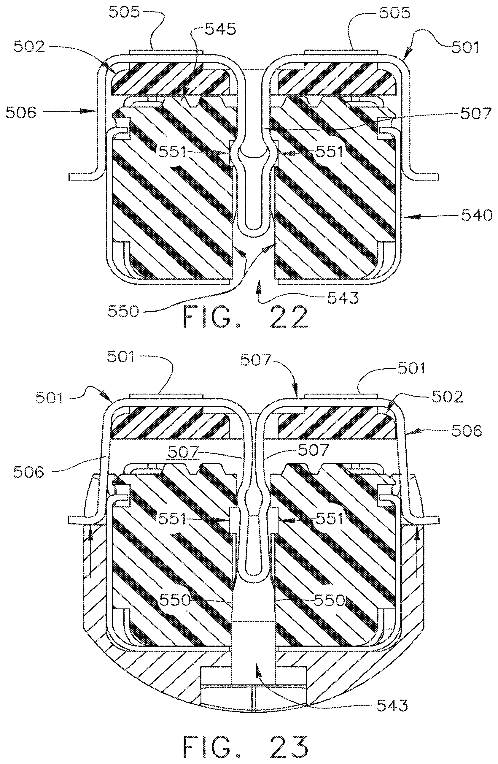
D00015
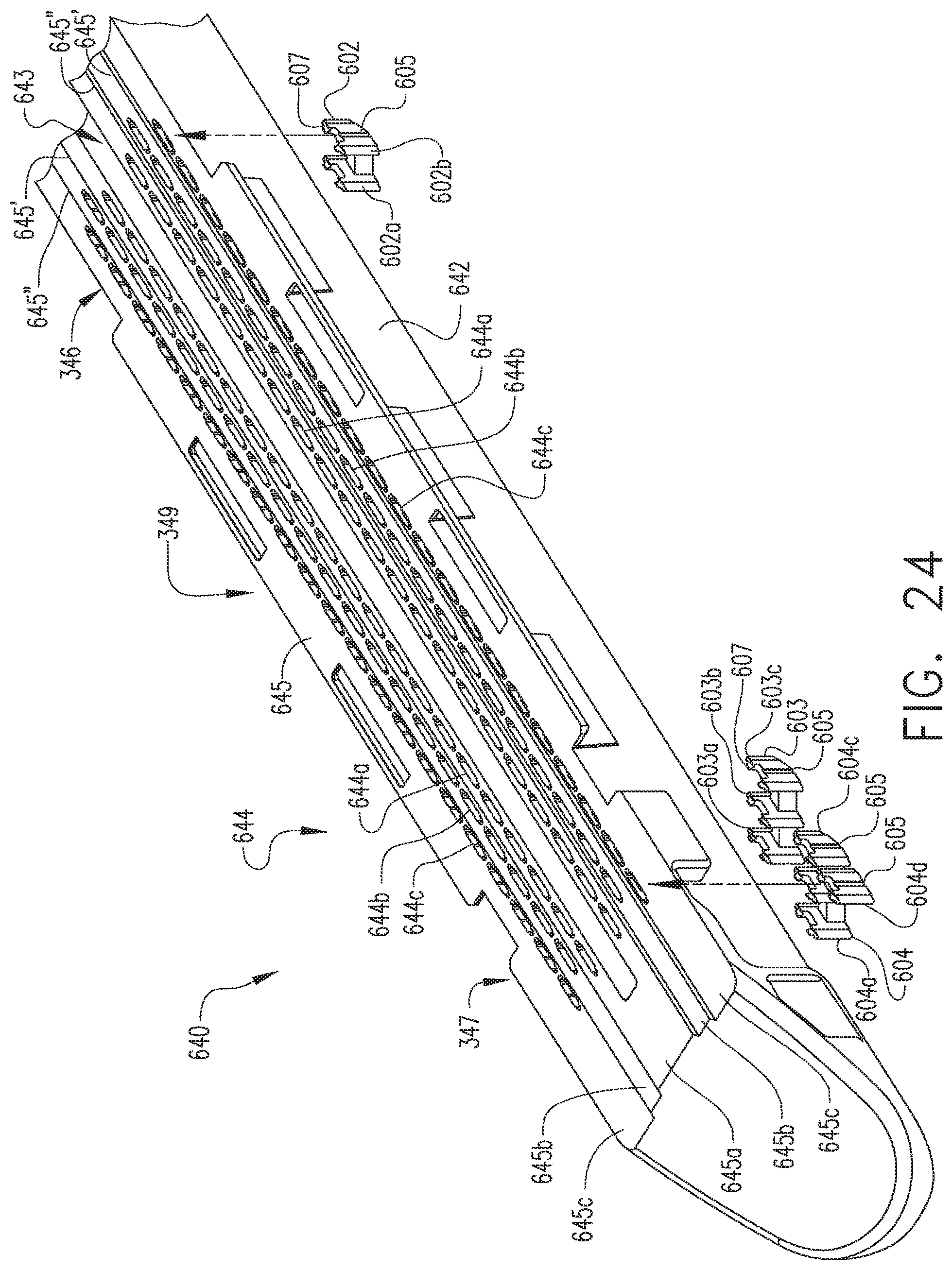
D00016

D00017

D00018

D00019

D00020

D00021
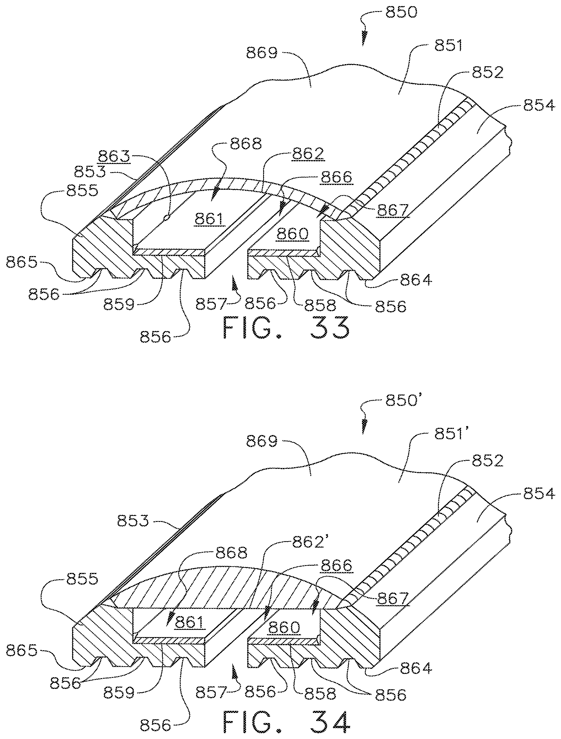
D00022

D00023
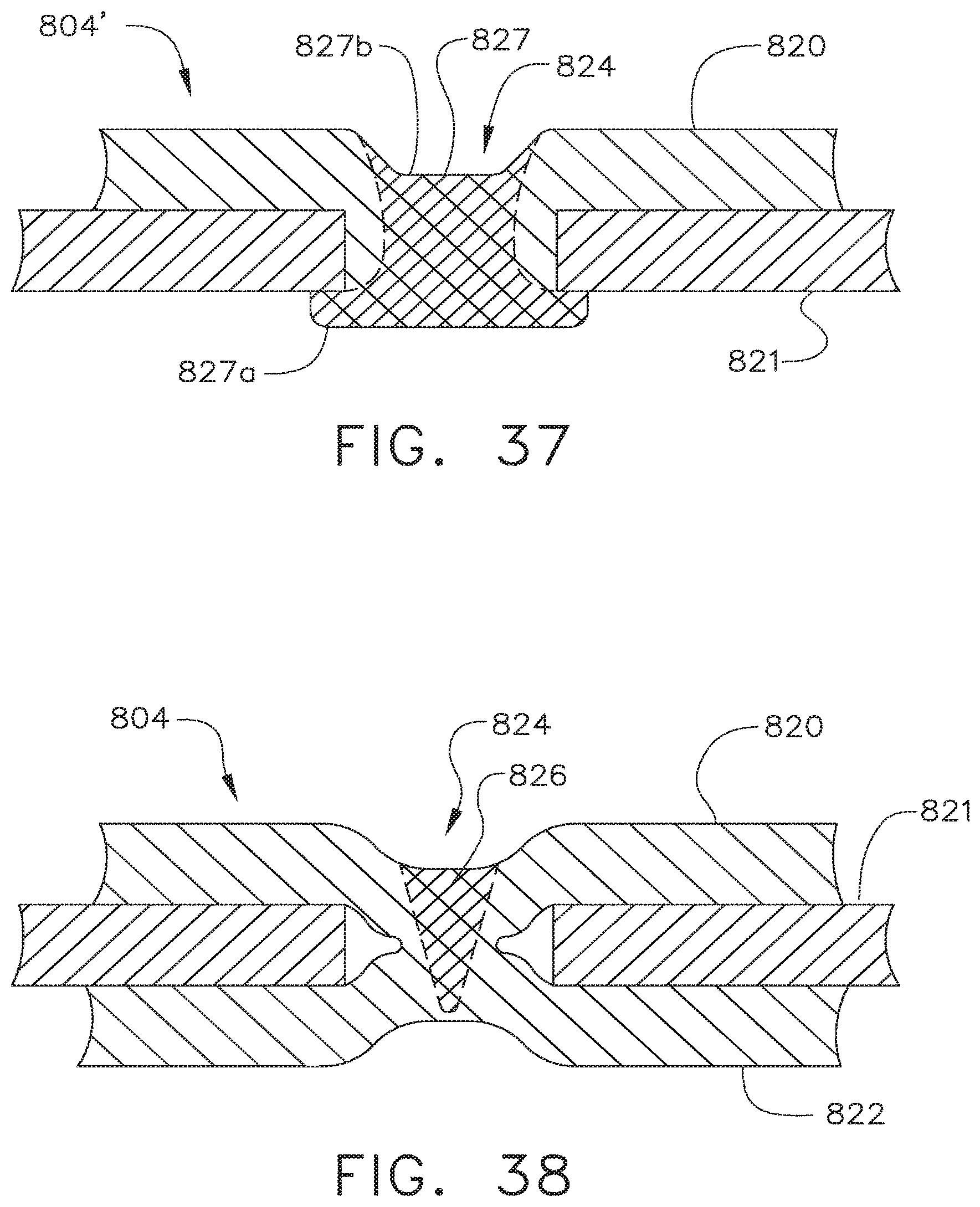
D00024

D00025
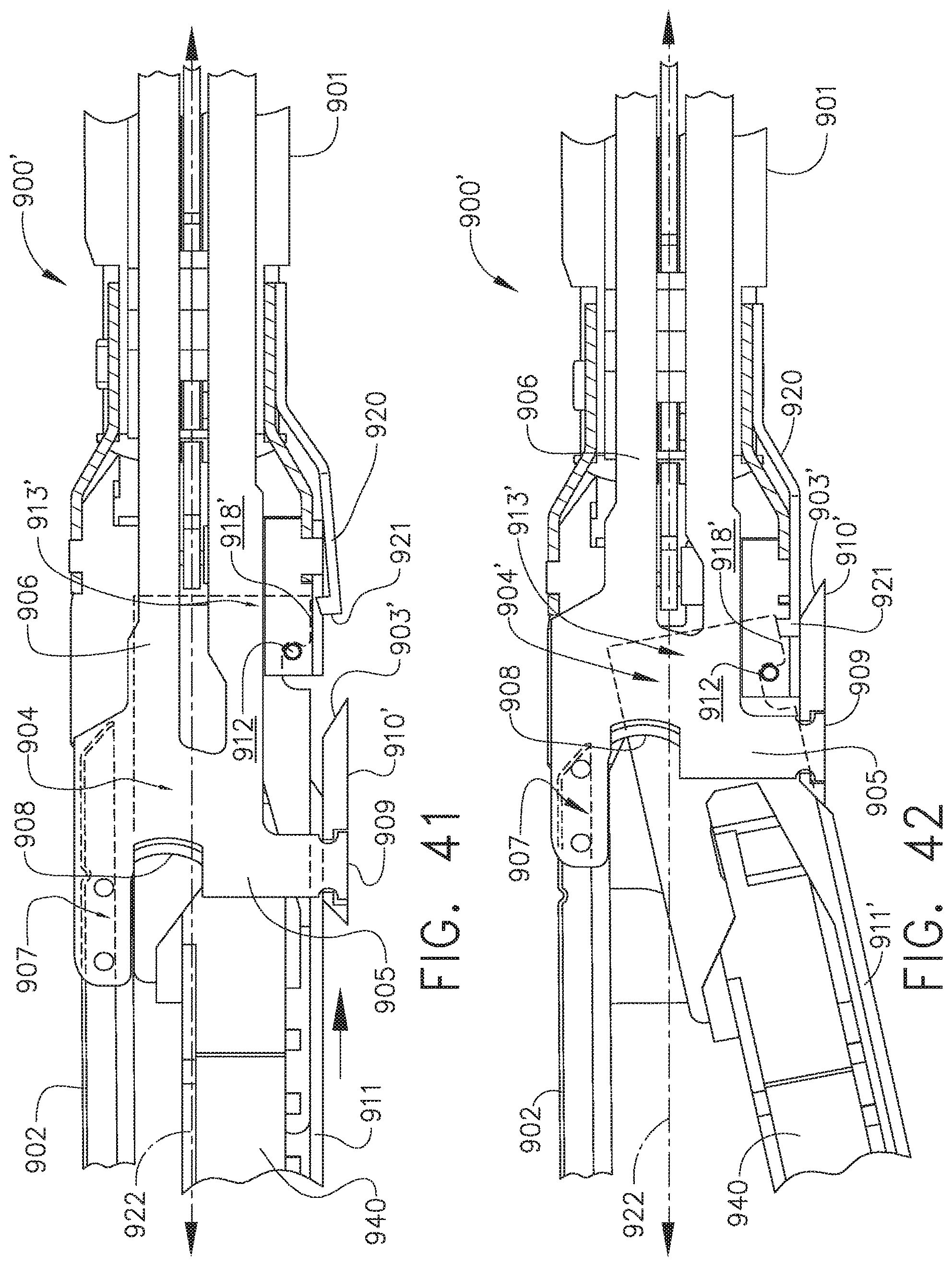
D00026

D00027

XML
uspto.report is an independent third-party trademark research tool that is not affiliated, endorsed, or sponsored by the United States Patent and Trademark Office (USPTO) or any other governmental organization. The information provided by uspto.report is based on publicly available data at the time of writing and is intended for informational purposes only.
While we strive to provide accurate and up-to-date information, we do not guarantee the accuracy, completeness, reliability, or suitability of the information displayed on this site. The use of this site is at your own risk. Any reliance you place on such information is therefore strictly at your own risk.
All official trademark data, including owner information, should be verified by visiting the official USPTO website at www.uspto.gov. This site is not intended to replace professional legal advice and should not be used as a substitute for consulting with a legal professional who is knowledgeable about trademark law.