Suction and irrigation sealing grasper
Boudreaux , et al. March 30, 2
U.S. patent number 10,959,771 [Application Number 15/291,694] was granted by the patent office on 2021-03-30 for suction and irrigation sealing grasper. This patent grant is currently assigned to Ethicon LLC. The grantee listed for this patent is Ethicon Endo-Surgery, LLC. Invention is credited to Chad P. Boudreaux, Edward G. Chekan, Cory G. Kimball, Jeffrey D. Messerly, Christopher A. Papa, Peter K. Shires, Foster B. Stulen.


View All Diagrams
| United States Patent | 10,959,771 |
| Boudreaux , et al. | March 30, 2021 |
Suction and irrigation sealing grasper
Abstract
Aspects of the present disclosure are presented for a single surgical instrument configured for grasping tissue, performing sealing procedures using electrosurgical or ultrasonic energy, suctioning fluid, and providing irrigation. An end effector of the surgical instrument may include multiple members arranged in various configurations to collectively perform the aforementioned functions. The suction and irrigation elements may comprise one or more fluid paths configured to deliver fluid to or evacuate fluid from a surgical field. In this way, a user, such as a clinician or surgeon, may rely on a single surgical instrument to perform these tasks typical in surgery while having an extra hand available and so as to not need to divert his or her concentration away from the surgical site in order to access multiple devices. Further, the timing for performing each of the functions may be made quicker, due to not needing to switch using multiple devices.
| Inventors: | Boudreaux; Chad P. (Cincinnati, OH), Shires; Peter K. (Hamilton, OH), Messerly; Jeffrey D. (Cincinnati, OH), Papa; Christopher A. (Cincinnati, OH), Kimball; Cory G. (Hamilton, OH), Stulen; Foster B. (Mason, OH), Chekan; Edward G. (Chapel Hill, NC) | ||||||||||
|---|---|---|---|---|---|---|---|---|---|---|---|
| Applicant: |
|
||||||||||
| Assignee: | Ethicon LLC (Guaynabo,
PR) |
||||||||||
| Family ID: | 1000005451776 | ||||||||||
| Appl. No.: | 15/291,694 | ||||||||||
| Filed: | October 12, 2016 |
Prior Publication Data
| Document Identifier | Publication Date | |
|---|---|---|
| US 20170105789 A1 | Apr 20, 2017 | |
Related U.S. Patent Documents
| Application Number | Filing Date | Patent Number | Issue Date | ||
|---|---|---|---|---|---|
| 62285019 | Oct 16, 2015 | ||||
| Current U.S. Class: | 1/1 |
| Current CPC Class: | A61B 18/1445 (20130101); A61B 2017/320093 (20170801); A61B 2218/007 (20130101); A61B 2017/320095 (20170801); A61B 2018/0063 (20130101); A61B 2218/002 (20130101) |
| Current International Class: | A61B 18/14 (20060101); A61B 18/00 (20060101); A61B 17/32 (20060101) |
| Field of Search: | ;606/51-52,169,205-207 |
References Cited [Referenced By]
U.S. Patent Documents
| 2366274 | January 1945 | Luth et al. |
| 2458152 | January 1949 | Eakins |
| 2510693 | June 1950 | Green |
| 2736960 | March 1956 | Armstrong |
| 2849788 | September 1958 | Creek |
| 2867039 | January 1959 | Zach |
| 3015961 | January 1962 | Roney |
| 3043309 | July 1962 | McCarthy |
| 3166971 | January 1965 | Stoecker |
| 3358676 | December 1967 | Frei et al. |
| 3525912 | August 1970 | Wallin |
| 3526219 | September 1970 | Balamuth |
| 3580841 | May 1971 | Cadotte et al. |
| 3614484 | October 1971 | Shoh |
| 3636943 | January 1972 | Balamuth |
| 3703651 | November 1972 | Blowers |
| 3710399 | January 1973 | Hurst |
| 3776238 | December 1973 | Peyman et al. |
| 3777760 | December 1973 | Essner |
| 3805787 | April 1974 | Banko |
| 3862630 | January 1975 | Balamuth |
| 3900823 | August 1975 | Sokal et al. |
| 3906217 | September 1975 | Lackore |
| 3918442 | November 1975 | Nikolaev et al. |
| 3946738 | March 1976 | Newton et al. |
| 3955859 | May 1976 | Stella et al. |
| 3956826 | May 1976 | Perdreaux, Jr. |
| 3988535 | October 1976 | Hickman et al. |
| 4005714 | February 1977 | Hiltebrandt |
| 4034762 | July 1977 | Cosens et al. |
| 4047136 | September 1977 | Satto |
| 4058126 | November 1977 | Leveen |
| 4063561 | December 1977 | McKenna |
| 4099192 | July 1978 | Aizawa et al. |
| 4156187 | May 1979 | Murry et al. |
| 4188927 | February 1980 | Harris |
| 4200106 | April 1980 | Douvas et al. |
| 4203430 | May 1980 | Takahashi |
| 4220154 | September 1980 | Semm |
| 4237441 | December 1980 | van Konynenburg et al. |
| 4278077 | July 1981 | Mizumoto |
| 4281785 | August 1981 | Brooks |
| 4304987 | December 1981 | van Konynenburg |
| 4314559 | February 1982 | Allen |
| 4384584 | May 1983 | Chen |
| 4445063 | April 1984 | Smith |
| 4463759 | August 1984 | Garito et al. |
| 4491132 | January 1985 | Aikins |
| 4492231 | January 1985 | Auth |
| 4535773 | August 1985 | Yoon |
| 4545926 | October 1985 | Fouts, Jr. et al. |
| 4550870 | November 1985 | Krumme et al. |
| 4582236 | April 1986 | Hirose |
| 4585282 | April 1986 | Bosley |
| 4597390 | July 1986 | Mulhollan et al. |
| 4617927 | October 1986 | Manes |
| 4633874 | January 1987 | Chow et al. |
| 4634420 | January 1987 | Spinosa et al. |
| 4640279 | February 1987 | Beard |
| 4655746 | April 1987 | Daniels et al. |
| 4671287 | June 1987 | Fiddian-Green |
| 4708127 | November 1987 | Abdelghani |
| 4735603 | April 1988 | Goodson et al. |
| 4761871 | August 1988 | O'Connor et al. |
| 4777951 | October 1988 | Cribier et al. |
| 4797803 | January 1989 | Carroll |
| 4798588 | January 1989 | Aillon |
| 4802461 | February 1989 | Cho |
| 4803506 | February 1989 | Diehl et al. |
| 4830462 | May 1989 | Karny et al. |
| 4832683 | May 1989 | Idemoto et al. |
| 4838853 | June 1989 | Parisi |
| 4849133 | July 1989 | Yoshida et al. |
| 4850354 | July 1989 | McGurk-Burleson et al. |
| 4860745 | August 1989 | Farin et al. |
| 4865159 | September 1989 | Jamison |
| 4878493 | November 1989 | Pasternak et al. |
| 4880015 | November 1989 | Nierman |
| 4896009 | January 1990 | Pawlowski |
| 4910389 | March 1990 | Sherman et al. |
| 4910633 | March 1990 | Quinn |
| 4911148 | March 1990 | Sosnowski et al. |
| 4919129 | April 1990 | Weber, Jr. et al. |
| 4920978 | May 1990 | Colvin |
| 4922902 | May 1990 | Wuchinich et al. |
| 4936842 | June 1990 | D'Amelio et al. |
| 4961738 | October 1990 | Mackin |
| 4967670 | November 1990 | Morishita et al. |
| 4981756 | January 1991 | Rhandhawa |
| 5007919 | April 1991 | Silva et al. |
| 5019075 | May 1991 | Spears et al. |
| 5020514 | June 1991 | Heckele |
| 5026387 | June 1991 | Thomas |
| 5061269 | October 1991 | Muller |
| 5093754 | March 1992 | Kawashima |
| 5099216 | March 1992 | Pelrine |
| 5099840 | March 1992 | Goble et al. |
| 5104025 | April 1992 | Main et al. |
| 5106538 | April 1992 | Barma et al. |
| 5108383 | April 1992 | White |
| 5112300 | May 1992 | Ureche |
| 5123903 | June 1992 | Quaid et al. |
| 5150102 | September 1992 | Takashima |
| 5150272 | September 1992 | Danley et al. |
| 5156633 | October 1992 | Smith |
| 5160334 | November 1992 | Billings et al. |
| 5162044 | November 1992 | Gahn et al. |
| 5167725 | December 1992 | Clark et al. |
| D332660 | January 1993 | Rawson et al. |
| 5176695 | January 1993 | Dulebohn |
| 5184605 | February 1993 | Grzeszykowski |
| 5188102 | February 1993 | Idemoto et al. |
| 5190541 | March 1993 | Abele et al. |
| 5196007 | March 1993 | Ellman et al. |
| 5205459 | April 1993 | Brinkerhoff et al. |
| 5205817 | April 1993 | Idemoto et al. |
| 5209719 | May 1993 | Baruch et al. |
| 5213569 | May 1993 | Davis |
| 5217460 | June 1993 | Knoepfler |
| 5221282 | June 1993 | Wuchinich |
| 5226910 | July 1993 | Kajiyama et al. |
| 5234428 | August 1993 | Kaufman |
| 5241236 | August 1993 | Sasaki et al. |
| 5253647 | October 1993 | Takahashi et al. |
| 5254130 | October 1993 | Poncet et al. |
| 5257988 | November 1993 | L'Esperance, Jr. |
| 5258004 | November 1993 | Bales et al. |
| 5258006 | November 1993 | Rydell et al. |
| 5261922 | November 1993 | Hood |
| 5263957 | November 1993 | Davison |
| 5267091 | November 1993 | Chen |
| 5282800 | February 1994 | Foshee et al. |
| 5285945 | February 1994 | Brinkerhoff et al. |
| 5290286 | March 1994 | Parins |
| 5293863 | March 1994 | Zhu et al. |
| 5304115 | April 1994 | Pflueger et al. |
| D347474 | May 1994 | Olson |
| 5309927 | May 1994 | Welch |
| 5312023 | May 1994 | Green et al. |
| 5313306 | May 1994 | Kuban et al. |
| 5318563 | June 1994 | Malis et al. |
| 5318564 | June 1994 | Eggers |
| 5318565 | June 1994 | Kuriloff et al. |
| 5318570 | June 1994 | Hood et al. |
| 5318589 | June 1994 | Lichtman |
| 5322055 | June 1994 | Davison et al. |
| 5324260 | June 1994 | O'Neill et al. |
| 5324299 | June 1994 | Davison et al. |
| 5326013 | July 1994 | Green et al. |
| 5330471 | July 1994 | Eggers |
| 5330502 | July 1994 | Hassler et al. |
| 5333624 | August 1994 | Tovey |
| 5339723 | August 1994 | Huitema |
| 5342359 | August 1994 | Rydell |
| 5344420 | September 1994 | Hilal et al. |
| 5346502 | September 1994 | Estabrook et al. |
| 5352219 | October 1994 | Reddy |
| 5359992 | November 1994 | Hori et al. |
| 5361583 | November 1994 | Huitema |
| 5366466 | November 1994 | Christian et al. |
| 5370640 | December 1994 | Kolff |
| D354564 | January 1995 | Medema |
| 5381067 | January 1995 | Greenstein et al. |
| 5383874 | January 1995 | Jackson et al. |
| 5387207 | February 1995 | Dyer et al. |
| 5389098 | February 1995 | Tsuruta et al. |
| 5395033 | March 1995 | Byrne et al. |
| 5395312 | March 1995 | Desai |
| 5395331 | March 1995 | O'Oneill et al. |
| 5395363 | March 1995 | Billings et al. |
| 5395364 | March 1995 | Anderhub et al. |
| 5396266 | March 1995 | Brimhall |
| 5396900 | March 1995 | Slater et al. |
| 5403312 | April 1995 | Yates et al. |
| 5409483 | April 1995 | Campbell et al. |
| D358887 | May 1995 | Feinberg |
| 5411481 | May 1995 | Allen et al. |
| 5413575 | May 1995 | Haenggi |
| 5417709 | May 1995 | Slater |
| 5419761 | May 1995 | Narayanan et al. |
| 5421829 | June 1995 | Olichney et al. |
| 5428504 | June 1995 | Bhatla |
| 5429131 | July 1995 | Scheinman et al. |
| 5431640 | July 1995 | Gabriel |
| 5443463 | August 1995 | Stern et al. |
| 5445615 | August 1995 | Yoon |
| 5445638 | August 1995 | Rydell et al. |
| 5449370 | September 1995 | Vaitekunas |
| 5451227 | September 1995 | Michaelson |
| 5456684 | October 1995 | Schmidt et al. |
| 5458598 | October 1995 | Feinberg et al. |
| 5462604 | October 1995 | Shibano et al. |
| 5465895 | November 1995 | Knodel et al. |
| 5472443 | December 1995 | Cordis et al. |
| 5476479 | December 1995 | Green et al. |
| 5477788 | December 1995 | Morishita |
| 5478003 | December 1995 | Green et al. |
| 5480409 | January 1996 | Riza |
| 5483501 | January 1996 | Park et al. |
| 5484436 | January 1996 | Eggers et al. |
| 5486162 | January 1996 | Brumbach |
| 5486189 | January 1996 | Mudry et al. |
| 5489256 | February 1996 | Adair |
| 5496317 | March 1996 | Goble et al. |
| 5500216 | March 1996 | Julian et al. |
| 5501654 | March 1996 | Failla et al. |
| 5504650 | April 1996 | Katsui et al. |
| 5505693 | April 1996 | Mackool |
| 5509922 | April 1996 | Aranyi et al. |
| 5511556 | April 1996 | DeSantis |
| 5520704 | May 1996 | Castro et al. |
| 5522839 | June 1996 | Pilling |
| 5531744 | July 1996 | Nardella et al. |
| 5540648 | July 1996 | Yoon |
| 5540681 | July 1996 | Strul et al. |
| 5542916 | August 1996 | Hirsch et al. |
| 5542938 | August 1996 | Avellanet et al. |
| 5558671 | September 1996 | Yates |
| 5562609 | October 1996 | Brumbach |
| 5562610 | October 1996 | Brumbach |
| 5562657 | October 1996 | Griffin |
| 5563179 | October 1996 | Stone et al. |
| 5569164 | October 1996 | Lurz |
| 5571121 | November 1996 | Heifetz |
| 5573534 | November 1996 | Stone |
| 5584830 | December 1996 | Ladd et al. |
| 5599350 | February 1997 | Schulze et al. |
| 5601601 | February 1997 | Tal et al. |
| 5604531 | February 1997 | Iddan et al. |
| 5607436 | March 1997 | Pratt et al. |
| 5607450 | March 1997 | Zvenyatsky et al. |
| 5611813 | March 1997 | Lichtman |
| 5618307 | April 1997 | Donlon et al. |
| 5618492 | April 1997 | Auten et al. |
| 5624452 | April 1997 | Yates |
| 5626578 | May 1997 | Tihon |
| 5628760 | May 1997 | Knoepfler |
| 5630420 | May 1997 | Vaitekunas |
| 5632432 | May 1997 | Schulze et al. |
| D381077 | July 1997 | Hunt |
| 5643175 | July 1997 | Adair |
| 5645065 | July 1997 | Shapiro et al. |
| 5647871 | July 1997 | Levine et al. |
| 5651780 | July 1997 | Jackson et al. |
| 5653677 | August 1997 | Okada et al. |
| 5653713 | August 1997 | Michelson |
| 5657697 | August 1997 | Murai |
| 5658281 | August 1997 | Heard |
| 5662667 | September 1997 | Knodel |
| 5665085 | September 1997 | Nardella |
| 5665100 | September 1997 | Yoon |
| 5669922 | September 1997 | Hood |
| 5674219 | October 1997 | Monson et al. |
| 5674220 | October 1997 | Fox et al. |
| 5674235 | October 1997 | Parisi |
| 5681260 | October 1997 | Ueda et al. |
| 5688270 | November 1997 | Yates et al. |
| 5690269 | November 1997 | Bolanos et al. |
| 5693051 | December 1997 | Schulze et al. |
| 5694936 | December 1997 | Fujimoto et al. |
| 5700243 | December 1997 | Narciso, Jr. |
| 5700261 | December 1997 | Brinkerhoff |
| 5704900 | January 1998 | Dobrovolny et al. |
| 5709680 | January 1998 | Yates et al. |
| 5711472 | January 1998 | Bryan |
| 5713896 | February 1998 | Nardella |
| 5716366 | February 1998 | Yates |
| 5720742 | February 1998 | Zacharias |
| 5720744 | February 1998 | Eggleston et al. |
| 5722326 | March 1998 | Post |
| 5722426 | March 1998 | Kolff |
| 5732636 | March 1998 | Wang et al. |
| 5733074 | March 1998 | Stock et al. |
| 5735848 | April 1998 | Yates et al. |
| 5738652 | April 1998 | Boyd et al. |
| 5741226 | April 1998 | Strukel et al. |
| 5741305 | April 1998 | Vincent et al. |
| 5743906 | April 1998 | Parins et al. |
| 5752973 | May 1998 | Kieturakis |
| 5755717 | May 1998 | Yates et al. |
| 5762255 | June 1998 | Chrisman et al. |
| 5776130 | July 1998 | Buysse et al. |
| 5779701 | July 1998 | McBrayer et al. |
| 5782834 | July 1998 | Lucey et al. |
| 5792135 | August 1998 | Madhani et al. |
| 5792138 | August 1998 | Shipp |
| 5796188 | August 1998 | Bays |
| 5797941 | August 1998 | Schulze et al. |
| 5800432 | September 1998 | Swanson |
| 5800449 | September 1998 | Wales |
| 5805140 | September 1998 | Rosenberg et al. |
| 5807393 | September 1998 | Williamson, IV et al. |
| 5810718 | September 1998 | Akiba et al. |
| 5810811 | September 1998 | Yates et al. |
| 5810859 | September 1998 | DiMatteo et al. |
| 5817033 | October 1998 | DeSantis et al. |
| 5817084 | October 1998 | Jensen |
| 5817093 | October 1998 | Williamson, IV et al. |
| 5827323 | October 1998 | Klieman et al. |
| 5828160 | October 1998 | Sugishita |
| 5836867 | November 1998 | Speier et al. |
| 5836909 | November 1998 | Cosmescu |
| 5836943 | November 1998 | Miller, III |
| 5836990 | November 1998 | Li |
| 5843109 | December 1998 | Mehta et al. |
| 5853412 | December 1998 | Mayenberger |
| 5876401 | March 1999 | Schulze et al. |
| 5878193 | March 1999 | Wang et al. |
| 5879364 | March 1999 | Bromfield et al. |
| 5880668 | March 1999 | Hall |
| 5883454 | March 1999 | Hones et al. |
| 5887018 | March 1999 | Bayazitoglu et al. |
| 5891142 | April 1999 | Eggers et al. |
| 5893835 | April 1999 | Witt et al. |
| 5897569 | April 1999 | Kellogg et al. |
| 5902239 | May 1999 | Buurman |
| 5904147 | May 1999 | Conlan et al. |
| 5906579 | May 1999 | Vander Salm et al. |
| 5906625 | May 1999 | Bito et al. |
| 5910129 | June 1999 | Koblish et al. |
| 5921956 | July 1999 | Grinberg et al. |
| 5929846 | July 1999 | Rosenberg et al. |
| 5935143 | August 1999 | Hood |
| 5935144 | August 1999 | Estabrook |
| 5938633 | August 1999 | Beaupre |
| 5944298 | August 1999 | Koike |
| 5944718 | August 1999 | Austin et al. |
| 5944737 | August 1999 | Tsonton et al. |
| 5954736 | September 1999 | Bishop et al. |
| 5954746 | September 1999 | Holthaus et al. |
| 5957849 | September 1999 | Munro |
| 5957882 | September 1999 | Nita et al. |
| 5957943 | September 1999 | Vaitekunas |
| 5968007 | October 1999 | Simon et al. |
| 5968060 | October 1999 | Kellogg |
| D416089 | November 1999 | Barton et al. |
| 5984938 | November 1999 | Yoon |
| 5989182 | November 1999 | Hori et al. |
| 5989274 | November 1999 | Davison et al. |
| 5989275 | November 1999 | Estabrook et al. |
| 5993972 | November 1999 | Reich et al. |
| 6003517 | December 1999 | Sheffield et al. |
| 6007484 | December 1999 | Thompson |
| 6013052 | January 2000 | Durman et al. |
| 6014580 | January 2000 | Blume et al. |
| 6024741 | February 2000 | Williamson, IV et al. |
| 6024744 | February 2000 | Kese et al. |
| 6033375 | March 2000 | Brumbach |
| 6033399 | March 2000 | Gines |
| 6039734 | March 2000 | Goble |
| 6050996 | April 2000 | Schmaltz et al. |
| 6053172 | April 2000 | Hovda et al. |
| 6063098 | May 2000 | Houser et al. |
| 6066132 | May 2000 | Chen et al. |
| 6068629 | May 2000 | Haissaguerre et al. |
| 6068647 | May 2000 | Witt et al. |
| 6074389 | June 2000 | Levine et al. |
| 6077285 | June 2000 | Boukhny |
| 6080152 | June 2000 | Nardella et al. |
| 6083151 | July 2000 | Renner et al. |
| 6083191 | July 2000 | Rose |
| 6086584 | July 2000 | Miller |
| 6090120 | July 2000 | Wright et al. |
| 6091995 | July 2000 | Ingle et al. |
| 6099483 | August 2000 | Palmer et al. |
| 6099550 | August 2000 | Yoon |
| 6109500 | August 2000 | Alli et al. |
| 6113594 | September 2000 | Savage |
| 6113598 | September 2000 | Baker |
| 6123466 | September 2000 | Persson et al. |
| H1904 | October 2000 | Yates et al. |
| 6127757 | October 2000 | Swinbanks |
| 6132368 | October 2000 | Cooper |
| 6139320 | October 2000 | Hahn |
| 6144402 | November 2000 | Norsworthy et al. |
| 6152902 | November 2000 | Christian et al. |
| 6152923 | November 2000 | Ryan |
| 6154198 | November 2000 | Rosenberg |
| 6159160 | December 2000 | Hsei et al. |
| 6159175 | December 2000 | Strukel et al. |
| 6162208 | December 2000 | Hipps |
| 6173199 | January 2001 | Gabriel |
| 6173715 | January 2001 | Sinanan et al. |
| 6174309 | January 2001 | Wrublewski et al. |
| 6176857 | January 2001 | Ashley |
| 6190386 | February 2001 | Rydell |
| 6193709 | February 2001 | Miyawaki et al. |
| 6206844 | March 2001 | Reichel et al. |
| 6206876 | March 2001 | Levine et al. |
| 6206877 | March 2001 | Kese et al. |
| 6210403 | April 2001 | Klicek |
| 6214023 | April 2001 | Whipple et al. |
| 6219572 | April 2001 | Young |
| 6221007 | April 2001 | Green |
| 6228080 | May 2001 | Gines |
| 6228084 | May 2001 | Kirwan, Jr. |
| 6231565 | May 2001 | Tovey et al. |
| 6233476 | May 2001 | Strommer et al. |
| 6238366 | May 2001 | Savage et al. |
| 6241724 | June 2001 | Fleischman et al. |
| 6248074 | June 2001 | Ohno et al. |
| D444365 | July 2001 | Bass et al. |
| 6254623 | July 2001 | Haibel, Jr. et al. |
| 6258034 | July 2001 | Hanafy |
| 6258086 | July 2001 | Ashley et al. |
| 6259230 | July 2001 | Chou |
| 6267761 | July 2001 | Ryan |
| 6270831 | August 2001 | Kumar et al. |
| 6273852 | August 2001 | Lehe et al. |
| 6273887 | August 2001 | Yamauchi et al. |
| 6274963 | August 2001 | Estabrook et al. |
| 6277115 | August 2001 | Saadat |
| 6277117 | August 2001 | Tetzlaff et al. |
| 6278218 | August 2001 | Madan et al. |
| 6283981 | September 2001 | Beaupre |
| 6292700 | September 2001 | Morrison et al. |
| 6309400 | October 2001 | Beaupre |
| 6315789 | November 2001 | Cragg |
| 6319221 | November 2001 | Savage et al. |
| 6325799 | December 2001 | Goble |
| 6325811 | December 2001 | Messerly |
| 6328751 | December 2001 | Beaupre |
| 6340878 | January 2002 | Oglesbee |
| 6352532 | March 2002 | Kramer et al. |
| 6364888 | April 2002 | Niemeyer et al. |
| 6371952 | April 2002 | Madhani et al. |
| 6379320 | April 2002 | Lafon et al. |
| 6379351 | April 2002 | Thapliyal et al. |
| D457958 | May 2002 | Dycus et al. |
| 6383194 | May 2002 | Pothula |
| 6387094 | May 2002 | Eitenmuller |
| 6387109 | May 2002 | Davison et al. |
| 6388657 | May 2002 | Natoli |
| 6391026 | May 2002 | Hung et al. |
| 6391042 | May 2002 | Cimino |
| 6398779 | June 2002 | Buysse et al. |
| 6409722 | June 2002 | Hoey et al. |
| H2037 | July 2002 | Yates et al. |
| 6416469 | July 2002 | Phung et al. |
| 6416486 | July 2002 | Wampler |
| 6419675 | July 2002 | Gallo, Sr. |
| 6423073 | July 2002 | Bowman |
| 6423082 | July 2002 | Houser et al. |
| 6430446 | August 2002 | Knowlton |
| 6432118 | August 2002 | Messerly |
| 6436114 | August 2002 | Novak et al. |
| 6436115 | August 2002 | Beaupre |
| 6443968 | September 2002 | Holthaus et al. |
| 6443969 | September 2002 | Novak et al. |
| 6454781 | September 2002 | Witt et al. |
| 6454782 | September 2002 | Schwemberger |
| 6458128 | October 2002 | Schulze |
| 6458130 | October 2002 | Frazier et al. |
| 6458142 | October 2002 | Faller et al. |
| 6461363 | October 2002 | Gadberry et al. |
| 6464689 | October 2002 | Qin et al. |
| 6464702 | October 2002 | Schulze et al. |
| 6464703 | October 2002 | Bartel |
| 6471172 | October 2002 | Lemke et al. |
| 6475211 | November 2002 | Chess et al. |
| 6475216 | November 2002 | Mulier et al. |
| 6480796 | November 2002 | Wiener |
| 6485490 | November 2002 | Wampler et al. |
| 6491690 | December 2002 | Goble et al. |
| 6491691 | December 2002 | Morley et al. |
| 6491701 | December 2002 | Tierney et al. |
| 6491708 | December 2002 | Madan et al. |
| 6497715 | December 2002 | Satou |
| 6500112 | December 2002 | Khouri |
| 6500176 | December 2002 | Truckai et al. |
| 6500188 | December 2002 | Harper et al. |
| 6503248 | January 2003 | Levine |
| 6506208 | January 2003 | Hunt et al. |
| 6511480 | January 2003 | Tetzlaff et al. |
| 6514252 | February 2003 | Nezhat et al. |
| 6517565 | February 2003 | Whitman et al. |
| 6520960 | February 2003 | Blocher et al. |
| 6522909 | February 2003 | Garibaldi et al. |
| 6524316 | February 2003 | Nicholson et al. |
| 6531846 | March 2003 | Smith |
| 6533784 | March 2003 | Truckai et al. |
| 6537196 | March 2003 | Creighton, IV et al. |
| 6537272 | March 2003 | Christopherson et al. |
| 6537291 | March 2003 | Friedman et al. |
| 6540693 | April 2003 | Burbank et al. |
| 6543456 | April 2003 | Freeman |
| 6544260 | April 2003 | Markel et al. |
| 6551309 | April 2003 | LePivert |
| 6554829 | April 2003 | Schulze et al. |
| 6558376 | May 2003 | Bishop |
| 6561983 | May 2003 | Cronin et al. |
| 6562037 | May 2003 | Paton et al. |
| 6572632 | June 2003 | Zisterer et al. |
| 6572639 | June 2003 | Ingle et al. |
| 6575969 | June 2003 | Rittman, III et al. |
| 6582451 | June 2003 | Marucci et al. |
| 6584360 | June 2003 | Francischelli et al. |
| 6585735 | July 2003 | Frazier et al. |
| 6589200 | July 2003 | Schwemberger et al. |
| 6589239 | July 2003 | Khandkar et al. |
| 6594517 | July 2003 | Nevo |
| 6599321 | July 2003 | Hyde, Jr. |
| 6602252 | August 2003 | Mollenauer |
| 6610060 | August 2003 | Mulier et al. |
| 6616450 | September 2003 | Mossle et al. |
| 6616600 | September 2003 | Pauker |
| 6619529 | September 2003 | Green et al. |
| 6620129 | September 2003 | Stecker et al. |
| 6620161 | September 2003 | Schulze et al. |
| 6622731 | September 2003 | Daniel et al. |
| 6623482 | September 2003 | Pendekanti et al. |
| 6623501 | September 2003 | Heller et al. |
| 6626926 | September 2003 | Friedman et al. |
| 6633234 | October 2003 | Wiener et al. |
| 6635057 | October 2003 | Harano et al. |
| 6644532 | November 2003 | Green et al. |
| 6648817 | November 2003 | Schara et al. |
| 6651669 | November 2003 | Burnside |
| 6656177 | December 2003 | Truckai et al. |
| 6656198 | December 2003 | Tsonton et al. |
| 6662127 | December 2003 | Wiener et al. |
| 6663941 | December 2003 | Brown et al. |
| 6669690 | December 2003 | Okada |
| 6673248 | January 2004 | Chowdhury |
| 6676660 | January 2004 | Wampler et al. |
| 6678621 | January 2004 | Wiener et al. |
| 6679882 | January 2004 | Kornerup |
| 6679899 | January 2004 | Wiener et al. |
| 6682501 | January 2004 | Nelson et al. |
| 6682544 | January 2004 | Mastri et al. |
| 6695840 | February 2004 | Schulze |
| 6696844 | February 2004 | Wong et al. |
| 6716215 | April 2004 | David et al. |
| 6719684 | April 2004 | Kim et al. |
| 6719765 | April 2004 | Bonutti |
| 6722552 | April 2004 | Fenton, Jr. |
| 6726686 | April 2004 | Buysse et al. |
| 6731047 | May 2004 | Kauf et al. |
| 6733498 | May 2004 | Paton et al. |
| 6733506 | May 2004 | McDevitt et al. |
| 6736813 | May 2004 | Yamauchi et al. |
| 6743229 | June 2004 | Buysse et al. |
| 6746443 | June 2004 | Morley et al. |
| 6752815 | June 2004 | Beaupre |
| 6762535 | July 2004 | Take et al. |
| 6766202 | July 2004 | Underwood et al. |
| 6767349 | July 2004 | Ouchi |
| 6770072 | August 2004 | Truckai et al. |
| 6773409 | August 2004 | Truckai et al. |
| 6773434 | August 2004 | Ciarrocca |
| 6773435 | August 2004 | Schulze et al. |
| 6773444 | August 2004 | Messerly |
| 6775575 | August 2004 | Bommannan et al. |
| 6776165 | August 2004 | Jin |
| 6783524 | August 2004 | Anderson et al. |
| 6786382 | September 2004 | Hoffman |
| 6786383 | September 2004 | Stegelmann |
| 6789939 | September 2004 | Schrodinger et al. |
| 6790216 | September 2004 | Ishikawa |
| 6796981 | September 2004 | Wham et al. |
| D496997 | October 2004 | Dycus et al. |
| 6800085 | October 2004 | Selmon et al. |
| 6802843 | October 2004 | Truckai et al. |
| 6806317 | October 2004 | Morishita et al. |
| 6808491 | October 2004 | Kortenbach et al. |
| 6811842 | November 2004 | Ehrnsperger et al. |
| 6814731 | November 2004 | Swanson |
| 6817974 | November 2004 | Cooper et al. |
| 6821273 | November 2004 | Mollenauer |
| 6828712 | December 2004 | Battaglin et al. |
| 6832998 | December 2004 | Goble |
| 6835199 | December 2004 | McGuckin, Jr. et al. |
| 6840938 | January 2005 | Morley et al. |
| 6860880 | March 2005 | Treat et al. |
| 6869439 | March 2005 | White et al. |
| 6875220 | April 2005 | Du et al. |
| 6877647 | April 2005 | Green et al. |
| 6893435 | May 2005 | Goble |
| 6905497 | June 2005 | Truckai et al. |
| 6908463 | June 2005 | Treat et al. |
| 6908472 | June 2005 | Wiener et al. |
| 6913579 | July 2005 | Truckai et al. |
| 6926716 | August 2005 | Baker et al. |
| 6929622 | August 2005 | Chian |
| 6929632 | August 2005 | Nita et al. |
| 6929644 | August 2005 | Truckai et al. |
| 6936003 | August 2005 | Iddan |
| D509589 | September 2005 | Wells |
| 6939347 | September 2005 | Thompson |
| 6945981 | September 2005 | Donofrio et al. |
| 6953461 | October 2005 | McClurken et al. |
| D511145 | November 2005 | Donofrio et al. |
| 6959852 | November 2005 | Shelton, IV et al. |
| 6974462 | December 2005 | Sater |
| 6976844 | December 2005 | Hickok et al. |
| 6976969 | December 2005 | Messerly |
| 6977495 | December 2005 | Donofrio |
| 6984220 | January 2006 | Wuchinich |
| 6986738 | January 2006 | Glukhovsky et al. |
| 6986780 | January 2006 | Rudnick et al. |
| 6994709 | February 2006 | Iida |
| 7000818 | February 2006 | Shelton, IV et al. |
| 7004951 | February 2006 | Gibbens, III |
| 7011657 | March 2006 | Truckai et al. |
| 7029435 | April 2006 | Nakao |
| 7039453 | May 2006 | Mullick et al. |
| 7041083 | May 2006 | Chu et al. |
| 7041088 | May 2006 | Nawrocki et al. |
| 7041102 | May 2006 | Truckai et al. |
| 7044352 | May 2006 | Shelton, IV et al. |
| 7044937 | May 2006 | Kirwan et al. |
| 7052496 | May 2006 | Yamauchi |
| 7055731 | June 2006 | Shelton, IV et al. |
| 7056284 | June 2006 | Martone et al. |
| 7063699 | June 2006 | Hess et al. |
| 7066879 | June 2006 | Fowler et al. |
| 7066936 | June 2006 | Ryan |
| 7070597 | July 2006 | Truckai et al. |
| 7074219 | July 2006 | Levine et al. |
| 7077039 | July 2006 | Gass et al. |
| 7077853 | July 2006 | Kramer et al. |
| 7083579 | August 2006 | Yokoi et al. |
| 7083617 | August 2006 | Kortenbach et al. |
| 7083618 | August 2006 | Couture et al. |
| 7083619 | August 2006 | Truckai et al. |
| 7087054 | August 2006 | Truckai et al. |
| 7090673 | August 2006 | Dycus et al. |
| 7094235 | August 2006 | Francischelli |
| 7096560 | August 2006 | Oddsen, Jr. |
| 7101371 | September 2006 | Dycus et al. |
| 7101372 | September 2006 | Dycus et al. |
| 7101373 | September 2006 | Dycus et al. |
| 7108695 | September 2006 | Witt et al. |
| 7112201 | September 2006 | Truckai et al. |
| 7118564 | October 2006 | Ritchie et al. |
| 7118570 | October 2006 | Tetzlaff et al. |
| 7120498 | October 2006 | Imran et al. |
| 7124932 | October 2006 | Isaacson et al. |
| 7125409 | October 2006 | Truckai et al. |
| 7131970 | November 2006 | Moses et al. |
| 7131971 | November 2006 | Dycus et al. |
| 7135018 | November 2006 | Ryan et al. |
| 7135030 | November 2006 | Schwemberger et al. |
| 7137980 | November 2006 | Buysse et al. |
| 7143925 | December 2006 | Shelton, IV et al. |
| 7147138 | December 2006 | Shelton, IV |
| 7147638 | December 2006 | Chapman et al. |
| 7153315 | December 2006 | Miller |
| 7156189 | January 2007 | Bar-Cohen et al. |
| 7156846 | January 2007 | Dycus et al. |
| 7156853 | January 2007 | Muratsu |
| 7157058 | January 2007 | Marhasin et al. |
| 7159750 | January 2007 | Racenet et al. |
| 7160296 | January 2007 | Pearson et al. |
| 7160298 | January 2007 | Lawes et al. |
| 7163548 | January 2007 | Stulen et al. |
| 7169104 | January 2007 | Ueda et al. |
| 7169146 | January 2007 | Truckai et al. |
| 7169156 | January 2007 | Hart |
| 7170823 | January 2007 | Fabricius et al. |
| 7179271 | February 2007 | Friedman et al. |
| 7186253 | March 2007 | Truckai et al. |
| 7189233 | March 2007 | Truckai et al. |
| 7195631 | March 2007 | Dumbauld |
| D541418 | April 2007 | Schechter et al. |
| 7199545 | April 2007 | Oleynikov et al. |
| 7204820 | April 2007 | Akahoshi |
| 7207471 | April 2007 | Heinrich et al. |
| 7208005 | April 2007 | Frecker et al. |
| 7211094 | May 2007 | Gannoe et al. |
| 7220951 | May 2007 | Truckai et al. |
| 7223229 | May 2007 | Inman et al. |
| 7225964 | June 2007 | Mastri et al. |
| 7226448 | June 2007 | Bertolero et al. |
| 7229455 | June 2007 | Sakurai et al. |
| 7232440 | June 2007 | Dumbauld et al. |
| 7235064 | June 2007 | Hopper et al. |
| 7235073 | June 2007 | Levine et al. |
| 7241290 | July 2007 | Doyle et al. |
| 7241294 | July 2007 | Reschke |
| 7241296 | July 2007 | Buysse et al. |
| 7246734 | July 2007 | Shelton, IV |
| 7251531 | July 2007 | Mosher et al. |
| 7252667 | August 2007 | Moses et al. |
| 7255697 | August 2007 | Dycus et al. |
| 7267677 | September 2007 | Johnson et al. |
| 7267685 | September 2007 | Butaric et al. |
| 7270658 | September 2007 | Woloszko et al. |
| 7270664 | September 2007 | Johnson et al. |
| 7273483 | September 2007 | Wiener et al. |
| 7276065 | October 2007 | Morley et al. |
| 7282773 | October 2007 | Li et al. |
| 7287682 | October 2007 | Ezzat et al. |
| 7297145 | November 2007 | Woloszko et al. |
| 7297149 | November 2007 | Vitali et al. |
| 7300450 | November 2007 | Vleugels et al. |
| 7303557 | December 2007 | Wham et al. |
| 7307313 | December 2007 | Ohyanagi et al. |
| 7309849 | December 2007 | Truckai et al. |
| 7311709 | December 2007 | Truckai et al. |
| 7317955 | January 2008 | McGreevy |
| 7326236 | February 2008 | Andreas et al. |
| 7329257 | February 2008 | Kanehira et al. |
| 7331410 | February 2008 | Yong et al. |
| 7353068 | April 2008 | Tanaka et al. |
| 7354440 | April 2008 | Truckal et al. |
| 7357287 | April 2008 | Shelton, IV et al. |
| 7360542 | April 2008 | Nelson et al. |
| 7364577 | April 2008 | Wham et al. |
| 7367973 | May 2008 | Manzo et al. |
| 7367976 | May 2008 | Lawes et al. |
| 7371227 | May 2008 | Zeiner |
| RE40388 | June 2008 | Gines |
| 7380695 | June 2008 | Doll et al. |
| 7381209 | June 2008 | Truckai et al. |
| 7384420 | June 2008 | Dycus et al. |
| 7390317 | June 2008 | Taylor et al. |
| 7396356 | July 2008 | Mollenauer |
| 7403224 | July 2008 | Fuller et al. |
| 7404508 | July 2008 | Smith et al. |
| 7407077 | August 2008 | Ortiz et al. |
| 7408288 | August 2008 | Hara |
| 7416101 | August 2008 | Shelton, IV et al. |
| D576725 | September 2008 | Shumer et al. |
| 7422139 | September 2008 | Shelton, IV et al. |
| 7422586 | September 2008 | Morris et al. |
| 7422592 | September 2008 | Morley et al. |
| 7429259 | September 2008 | Cadeddu et al. |
| D578643 | October 2008 | Shumer et al. |
| D578644 | October 2008 | Shumer et al. |
| D578645 | October 2008 | Shumer et al. |
| 7431704 | October 2008 | Babaev |
| 7435249 | October 2008 | Buysse et al. |
| 7435582 | October 2008 | Zimmermann et al. |
| 7439732 | October 2008 | LaPlaca |
| 7441684 | October 2008 | Shelton, IV et al. |
| 7442193 | October 2008 | Shields et al. |
| 7442194 | October 2008 | Dumbauld et al. |
| 7445621 | November 2008 | Dumbauld et al. |
| 7448993 | November 2008 | Yokoi et al. |
| 7449004 | November 2008 | Yamada et al. |
| 7450998 | November 2008 | Zilberman et al. |
| 7451904 | November 2008 | Shelton, IV |
| 7464846 | December 2008 | Shelton, IV et al. |
| 7472815 | January 2009 | Shelton, IV et al. |
| 7473253 | January 2009 | Dycus et al. |
| 7479148 | January 2009 | Beaupre |
| 7479160 | January 2009 | Branch et al. |
| 7487899 | February 2009 | Shelton, IV et al. |
| 7488319 | February 2009 | Yates |
| 7491201 | February 2009 | Shields et al. |
| 7494468 | February 2009 | Rabiner et al. |
| 7494501 | February 2009 | Ahlberg et al. |
| 7498080 | March 2009 | Tung et al. |
| 7503893 | March 2009 | Kucklick |
| 7505812 | March 2009 | Eggers et al. |
| 7506791 | March 2009 | Omaits et al. |
| 7510107 | March 2009 | Timm et al. |
| 7510556 | March 2009 | Nguyen et al. |
| 7511733 | March 2009 | Takizawa et al. |
| 7513025 | April 2009 | Fischer |
| 7517349 | April 2009 | Truckai et al. |
| 7520877 | April 2009 | Lee, Jr. et al. |
| 7524320 | April 2009 | Tierney et al. |
| 7534243 | May 2009 | Chin et al. |
| D594983 | June 2009 | Price et al. |
| 7540872 | June 2009 | Schechter et al. |
| 7543730 | June 2009 | Marczyk |
| 7544200 | June 2009 | Houser |
| 7550216 | June 2009 | Ofer et al. |
| 7553309 | June 2009 | Buysse et al. |
| 7559452 | July 2009 | Wales et al. |
| 7566318 | July 2009 | Haefner |
| 7567012 | July 2009 | Namikawa |
| 7582086 | September 2009 | Privitera et al. |
| 7582087 | September 2009 | Tetzlaff et al. |
| 7586289 | September 2009 | Andruk et al. |
| 7588176 | September 2009 | Timm et al. |
| 7588177 | September 2009 | Racenet |
| 7594925 | September 2009 | Danek et al. |
| 7597693 | October 2009 | Garrison |
| 7599743 | October 2009 | Hassler, Jr. et al. |
| 7601119 | October 2009 | Shahinian |
| 7604150 | October 2009 | Boudreaux |
| 7611512 | November 2009 | Ein-Gal |
| 7617961 | November 2009 | Viola |
| 7621930 | November 2009 | Houser |
| 7625370 | December 2009 | Hart et al. |
| 7628791 | December 2009 | Garrison et al. |
| 7628792 | December 2009 | Guerra |
| 7632267 | December 2009 | Dahla |
| 7632269 | December 2009 | Truckai et al. |
| 7637410 | December 2009 | Marczyk |
| 7640447 | December 2009 | Qiu |
| 7641653 | January 2010 | Dalla Betta et al. |
| 7641671 | January 2010 | Crainich |
| 7644848 | January 2010 | Swayze et al. |
| 7645277 | January 2010 | McClurken et al. |
| 7648499 | January 2010 | Orszulak et al. |
| 7658311 | February 2010 | Boudreaux |
| 7662151 | February 2010 | Crompton, Jr. et al. |
| 7665647 | February 2010 | Shelton, IV et al. |
| 7666206 | February 2010 | Taniguchi et al. |
| 7670334 | March 2010 | Hueil et al. |
| 7678043 | March 2010 | Gilad |
| 7678105 | March 2010 | McGreevy et al. |
| 7686804 | March 2010 | Johnson et al. |
| 7691095 | April 2010 | Bednarek et al. |
| 7691098 | April 2010 | Wallace et al. |
| 7691103 | April 2010 | Fernandez et al. |
| 7703459 | April 2010 | Saadat et al. |
| 7703653 | April 2010 | Shah et al. |
| 7708735 | May 2010 | Chapman et al. |
| 7708751 | May 2010 | Hughes et al. |
| 7708758 | May 2010 | Lee et al. |
| 7717312 | May 2010 | Beetel |
| 7717914 | May 2010 | Kimura |
| 7717915 | May 2010 | Miyazawa |
| 7722527 | May 2010 | Bouchier et al. |
| 7722607 | May 2010 | Dumbauld et al. |
| 7725214 | May 2010 | Diolaiti |
| D618797 | June 2010 | Price et al. |
| 7726537 | June 2010 | Olson et al. |
| 7744615 | June 2010 | Couture |
| 7751115 | July 2010 | Song |
| 7753904 | July 2010 | Shelton, IV et al. |
| 7753908 | July 2010 | Swanson |
| 7753909 | July 2010 | Chapman et al. |
| 7762445 | July 2010 | Heinrich et al. |
| D621503 | August 2010 | Otten et al. |
| 7766210 | August 2010 | Shelton, IV et al. |
| 7766910 | August 2010 | Hixson et al. |
| 7770774 | August 2010 | Mastri et al. |
| 7770775 | August 2010 | Shelton, IV et al. |
| 7775972 | August 2010 | Brock et al. |
| 7776036 | August 2010 | Schechter et al. |
| 7776037 | August 2010 | Odom |
| 7780651 | August 2010 | Madhani et al. |
| 7780659 | August 2010 | Okada et al. |
| 7780663 | August 2010 | Yates et al. |
| 7784663 | August 2010 | Shelton, IV |
| 7789283 | September 2010 | Shah |
| 7789878 | September 2010 | Dumbauld et al. |
| 7789883 | September 2010 | Takashino et al. |
| 7793814 | September 2010 | Racenet et al. |
| 7799027 | September 2010 | Hafner |
| 7803156 | September 2010 | Eder et al. |
| 7806891 | October 2010 | Nowlin et al. |
| 7810692 | October 2010 | Hall et al. |
| 7810693 | October 2010 | Broehl et al. |
| 7815641 | October 2010 | Dodde et al. |
| 7819298 | October 2010 | Hall et al. |
| 7819299 | October 2010 | Shelton, IV et al. |
| 7819872 | October 2010 | Johnson et al. |
| D627066 | November 2010 | Romero |
| 7824401 | November 2010 | Manzo et al. |
| 7832408 | November 2010 | Shelton, IV et al. |
| 7832612 | November 2010 | Baxter, III et al. |
| 7837699 | November 2010 | Yamada et al. |
| 7845537 | December 2010 | Shelton, IV et al. |
| 7846159 | December 2010 | Morrison et al. |
| 7846160 | December 2010 | Payne et al. |
| 7850688 | December 2010 | Hafner |
| D631155 | January 2011 | Peine et al. |
| 7861906 | January 2011 | Doll et al. |
| 7862560 | January 2011 | Marion |
| 7867228 | January 2011 | Nobis et al. |
| 7871392 | January 2011 | Sartor |
| 7871423 | January 2011 | Livneh |
| D631965 | February 2011 | Price et al. |
| 7877852 | February 2011 | Unger et al. |
| 7877853 | February 2011 | Unger et al. |
| 7879035 | February 2011 | Garrison et al. |
| 7879070 | February 2011 | Ortiz et al. |
| 7887535 | February 2011 | Lands et al. |
| 7892606 | February 2011 | Thies et al. |
| 7896875 | March 2011 | Heim et al. |
| 7896878 | March 2011 | Johnson et al. |
| 7901400 | March 2011 | Wham et al. |
| 7901423 | March 2011 | Stulen et al. |
| 7905881 | March 2011 | Masuda et al. |
| 7909220 | March 2011 | Viola |
| 7919184 | April 2011 | Mohapatra et al. |
| 7922061 | April 2011 | Shelton, IV et al. |
| 7922651 | April 2011 | Yamada et al. |
| 7922953 | April 2011 | Guerra |
| 7931649 | April 2011 | Couture et al. |
| D637288 | May 2011 | Houghton |
| D638540 | May 2011 | Ijiri et al. |
| 7935114 | May 2011 | Takashino et al. |
| 7942303 | May 2011 | Shah |
| 7942868 | May 2011 | Cooper |
| 7951165 | May 2011 | Golden et al. |
| 7955331 | June 2011 | Truckai et al. |
| 7959050 | June 2011 | Smith et al. |
| 7959626 | June 2011 | Hong et al. |
| 7963963 | June 2011 | Francischelli et al. |
| 7967602 | June 2011 | Lindquist |
| 7976544 | July 2011 | McClurken et al. |
| 7980443 | July 2011 | Scheib et al. |
| 7981113 | July 2011 | Truckai et al. |
| 7988567 | August 2011 | Kim et al. |
| 7997278 | August 2011 | Utley et al. |
| 8020743 | September 2011 | Shelton, IV |
| 8033173 | October 2011 | Ehlert et al. |
| 8038612 | October 2011 | Paz |
| 8038693 | October 2011 | Allen |
| 8048070 | November 2011 | O'Orien et al. |
| 8052672 | November 2011 | Laufer et al. |
| 8056720 | November 2011 | Hawkes |
| 8056787 | November 2011 | Boudreaux et al. |
| 8057498 | November 2011 | Robertson |
| 8058771 | November 2011 | Giordano et al. |
| 8061014 | November 2011 | Smith et al. |
| 8062211 | November 2011 | Duval et al. |
| 8066167 | November 2011 | Measamer et al. |
| 8070036 | December 2011 | Knodel |
| 8070748 | December 2011 | Hixson et al. |
| 8075555 | December 2011 | Truckai et al. |
| 8075558 | December 2011 | Truckai et al. |
| 8092475 | January 2012 | Cotter et al. |
| 8100894 | January 2012 | Mucko et al. |
| 8105323 | January 2012 | Buysse et al. |
| 8105324 | January 2012 | Palanker et al. |
| 8114104 | February 2012 | Young et al. |
| 8114119 | February 2012 | Spivey et al. |
| 8128624 | March 2012 | Couture et al. |
| 8128657 | March 2012 | Shiono et al. |
| 8133218 | March 2012 | Daw et al. |
| 8136712 | March 2012 | Zingman |
| 8141762 | March 2012 | Bedi et al. |
| 8142461 | March 2012 | Houser et al. |
| 8147488 | April 2012 | Masuda |
| 8147508 | April 2012 | Madan et al. |
| 8152825 | April 2012 | Madan et al. |
| 8157145 | April 2012 | Shelton, IV et al. |
| 8161977 | April 2012 | Shelton, IV et al. |
| 8162940 | April 2012 | Johnson et al. |
| 8177794 | May 2012 | Cabrera et al. |
| 8182502 | May 2012 | Stulen et al. |
| 8186560 | May 2012 | Hess et al. |
| 8187166 | May 2012 | Kuth et al. |
| 8187267 | May 2012 | Pappone et al. |
| 8192433 | June 2012 | Johnson et al. |
| 8197472 | June 2012 | Lau et al. |
| 8197479 | June 2012 | Olson et al. |
| 8197494 | June 2012 | Jaggi et al. |
| 8197502 | June 2012 | Smith et al. |
| 8206212 | June 2012 | Iddings et al. |
| 8221415 | July 2012 | Francischelli |
| 8221416 | July 2012 | Townsend |
| 8226675 | July 2012 | Houser et al. |
| 8236019 | August 2012 | Houser |
| 8236020 | August 2012 | Smith et al. |
| 8241235 | August 2012 | Kahler et al. |
| 8241283 | August 2012 | Guerra et al. |
| 8241284 | August 2012 | Dycus et al. |
| 8241312 | August 2012 | Messerly |
| 8244368 | August 2012 | Sherman |
| 8246615 | August 2012 | Behnke |
| 8246618 | August 2012 | Bucciaglia et al. |
| 8251994 | August 2012 | McKenna et al. |
| 8252012 | August 2012 | Stulen |
| 8257352 | September 2012 | Lawes et al. |
| 8257377 | September 2012 | Wiener et al. |
| 8262563 | September 2012 | Bakos et al. |
| 8267300 | September 2012 | Boudreaux |
| 8267854 | September 2012 | Asada et al. |
| 8267935 | September 2012 | Couture et al. |
| 8273085 | September 2012 | Park et al. |
| 8277446 | October 2012 | Heard |
| 8277447 | October 2012 | Garrison et al. |
| 8277471 | October 2012 | Wiener et al. |
| 8282581 | October 2012 | Zhao et al. |
| 8282669 | October 2012 | Gerber et al. |
| 8287528 | October 2012 | Wham et al. |
| 8292886 | October 2012 | Kerr et al. |
| 8292888 | October 2012 | Whitman |
| 8298228 | October 2012 | Buysse et al. |
| 8298232 | October 2012 | Unger |
| 8303583 | November 2012 | Hosier et al. |
| 8306629 | November 2012 | Mioduski et al. |
| 8308040 | November 2012 | Huang et al. |
| 8319400 | November 2012 | Houser et al. |
| 8322455 | December 2012 | Shelton, IV et al. |
| 8323302 | December 2012 | Robertson et al. |
| 8323310 | December 2012 | Kingsley |
| 8328061 | December 2012 | Kasvikis |
| 8328761 | December 2012 | Widenhouse et al. |
| 8328834 | December 2012 | Isaacs et al. |
| 8333778 | December 2012 | Smith et al. |
| 8333779 | December 2012 | Smith et al. |
| 8334468 | December 2012 | Palmer et al. |
| 8334635 | December 2012 | Voegele et al. |
| 8338726 | December 2012 | Palmer et al. |
| 8343146 | January 2013 | Godara et al. |
| 8344596 | January 2013 | Nield et al. |
| 8348880 | January 2013 | Messerly et al. |
| 8348947 | January 2013 | Takashino et al. |
| 8348967 | January 2013 | Stulen |
| 8353297 | January 2013 | Dacquay et al. |
| 8357158 | January 2013 | McKenna et al. |
| 8361569 | January 2013 | Saito et al. |
| 8372064 | February 2013 | Douglass et al. |
| 8372099 | February 2013 | Deville et al. |
| 8372101 | February 2013 | Smith et al. |
| 8377053 | February 2013 | Orszulak |
| 8377059 | February 2013 | Deville et al. |
| 8377085 | February 2013 | Smith et al. |
| 8382754 | February 2013 | Odom et al. |
| 8382782 | February 2013 | Robertson et al. |
| 8382792 | February 2013 | Chojin |
| 8388646 | March 2013 | Chojin |
| 8388647 | March 2013 | Nau, Jr. et al. |
| 8394094 | March 2013 | Edwards et al. |
| 8394115 | March 2013 | Houser et al. |
| 8397971 | March 2013 | Yates et al. |
| 8398633 | March 2013 | Mueller |
| 8403926 | March 2013 | Nobis et al. |
| 8403948 | March 2013 | Deville et al. |
| 8403949 | March 2013 | Palmer et al. |
| 8403950 | March 2013 | Palmer et al. |
| 8409076 | April 2013 | Pang et al. |
| 8414577 | April 2013 | Boudreaux et al. |
| 8418349 | April 2013 | Smith et al. |
| 8419757 | April 2013 | Smith et al. |
| 8419758 | April 2013 | Smith et al. |
| 8419759 | April 2013 | Dietz |
| 8425410 | April 2013 | Murray et al. |
| 8425545 | April 2013 | Smith et al. |
| 8430811 | April 2013 | Hess et al. |
| 8430876 | April 2013 | Kappus et al. |
| 8430897 | April 2013 | Novak et al. |
| 8430898 | April 2013 | Wiener et al. |
| 8435257 | May 2013 | Smith et al. |
| 8439911 | May 2013 | Mueller |
| 8439939 | May 2013 | Deville et al. |
| 8444662 | May 2013 | Palmer et al. |
| 8444664 | May 2013 | Balanev et al. |
| 8453906 | June 2013 | Huang et al. |
| 8454599 | June 2013 | Inagaki et al. |
| 8454639 | June 2013 | Du et al. |
| 8460288 | June 2013 | Tamai et al. |
| 8460292 | June 2013 | Truckai et al. |
| 8461744 | June 2013 | Wiener et al. |
| 8469956 | June 2013 | McKenna et al. |
| 8469981 | June 2013 | Robertson et al. |
| 8475361 | July 2013 | Barlow et al. |
| 8475453 | July 2013 | Marczyk et al. |
| 8480703 | July 2013 | Nicholas et al. |
| 8484833 | July 2013 | Cunningham et al. |
| 8485413 | July 2013 | Scheib et al. |
| 8485970 | July 2013 | Widenhouse et al. |
| 8486057 | July 2013 | Behnke, II |
| 8486096 | July 2013 | Robertson et al. |
| 8491625 | July 2013 | Homer |
| 8496682 | July 2013 | Guerra et al. |
| 8512336 | August 2013 | Couture |
| 8512364 | August 2013 | Kowalski et al. |
| 8512365 | August 2013 | Wiener et al. |
| 8523889 | September 2013 | Stulen et al. |
| 8529437 | September 2013 | Taylor et al. |
| 8529565 | September 2013 | Masuda et al. |
| 8531064 | September 2013 | Robertson et al. |
| 8535311 | September 2013 | Schall |
| 8535340 | September 2013 | Allen |
| 8535341 | September 2013 | Allen |
| 8540128 | September 2013 | Shelton, IV et al. |
| 8542501 | September 2013 | Kyono |
| 8553430 | October 2013 | Melanson et al. |
| 8562516 | October 2013 | Saadat et al. |
| 8562592 | October 2013 | Conlon et al. |
| 8562598 | October 2013 | Falkenstein et al. |
| 8562604 | October 2013 | Nishimura |
| 8568390 | October 2013 | Mueller |
| 8568412 | October 2013 | Brandt et al. |
| 8569997 | October 2013 | Lee |
| 8574187 | November 2013 | Marion |
| 8574231 | November 2013 | Boudreaux et al. |
| 8579176 | November 2013 | Smith et al. |
| 8579928 | November 2013 | Robertson et al. |
| 8579937 | November 2013 | Gresham |
| 8591459 | November 2013 | Clymer et al. |
| 8591506 | November 2013 | Wham et al. |
| D695407 | December 2013 | Price et al. |
| 8596513 | December 2013 | Olson et al. |
| 8597182 | December 2013 | Stein et al. |
| 8597297 | December 2013 | Couture et al. |
| 8608044 | December 2013 | Hueil et al. |
| 8613383 | December 2013 | Beckman et al. |
| 8622274 | January 2014 | Yates et al. |
| 8623011 | January 2014 | Spivey |
| 8623016 | January 2014 | Fischer |
| 8623027 | January 2014 | Price et al. |
| 8623044 | January 2014 | Timm et al. |
| 8628529 | January 2014 | Aldridge et al. |
| 8632461 | January 2014 | Glossop |
| 8632539 | January 2014 | Twomey et al. |
| 8636648 | January 2014 | Gazdzinski |
| 8636736 | January 2014 | Yates et al. |
| 8636761 | January 2014 | Cunningham et al. |
| 8638428 | January 2014 | Brown |
| 8640788 | February 2014 | Dachs, II et al. |
| 8641712 | February 2014 | Couture |
| 8647350 | February 2014 | Mohan et al. |
| 8650728 | February 2014 | Wan et al. |
| 8652120 | February 2014 | Giordano et al. |
| 8652155 | February 2014 | Houser et al. |
| 8663220 | March 2014 | Wiener et al. |
| 8663222 | March 2014 | Anderson et al. |
| 8663223 | March 2014 | Masuda et al. |
| 8668691 | March 2014 | Heard |
| RE44834 | April 2014 | Dumbauld et al. |
| 8684253 | April 2014 | Giordano et al. |
| 8685020 | April 2014 | Weizman et al. |
| 8685056 | April 2014 | Evans et al. |
| 8696662 | April 2014 | Eder et al. |
| 8696665 | April 2014 | Hunt et al. |
| 8702609 | April 2014 | Hadjicostis |
| 8702704 | April 2014 | Shelton, IV et al. |
| 8708213 | April 2014 | Shelton, IV et al. |
| 8709035 | April 2014 | Johnson et al. |
| 8715270 | May 2014 | Weitzner et al. |
| 8715277 | May 2014 | Weizman |
| 8721640 | May 2014 | Taylor et al. |
| 8734443 | May 2014 | Hixson et al. |
| 8747238 | June 2014 | Shelton, IV et al. |
| 8747351 | June 2014 | Schultz |
| 8747404 | June 2014 | Boudreaux et al. |
| 8752264 | June 2014 | Ackley et al. |
| 8752749 | June 2014 | Moore et al. |
| 8753338 | June 2014 | Widenhouse et al. |
| 8758342 | June 2014 | Bales et al. |
| 8764747 | July 2014 | Cummings et al. |
| 8770459 | July 2014 | Racenet et al. |
| 8784418 | July 2014 | Romero |
| 8789740 | July 2014 | Baxter, III et al. |
| 8790342 | July 2014 | Stulen et al. |
| 8795274 | August 2014 | Hanna |
| 8795276 | August 2014 | Dietz et al. |
| 8795327 | August 2014 | Dietz et al. |
| 8800838 | August 2014 | Shelton, IV |
| 8801752 | August 2014 | Fortier et al. |
| 8807414 | August 2014 | Ross et al. |
| 8808319 | August 2014 | Houser et al. |
| 8814856 | August 2014 | Elmouelhi et al. |
| 8814865 | August 2014 | Reschke |
| 8814870 | August 2014 | Paraschiv et al. |
| 8827992 | September 2014 | Koss et al. |
| 8827995 | September 2014 | Schaller et al. |
| 8834466 | September 2014 | Cummings et al. |
| 8834488 | September 2014 | Farritor et al. |
| 8834518 | September 2014 | Faller et al. |
| 8845630 | September 2014 | Mehta et al. |
| 8851354 | October 2014 | Swensgard et al. |
| 8852184 | October 2014 | Kucklick |
| 8864757 | October 2014 | Klimovitch et al. |
| 8864761 | October 2014 | Johnson et al. |
| 8870867 | October 2014 | Walberg et al. |
| 8876858 | November 2014 | Braun |
| 8882766 | November 2014 | Couture et al. |
| 8882791 | November 2014 | Stulen |
| 8887373 | November 2014 | Brandt et al. |
| 8888776 | November 2014 | Dietz et al. |
| 8888783 | November 2014 | Young |
| 8888809 | November 2014 | Davison et al. |
| 8906016 | December 2014 | Boudreaux et al. |
| 8906017 | December 2014 | Rioux et al. |
| 8911438 | December 2014 | Swoyer et al. |
| 8911460 | December 2014 | Neurohr et al. |
| 8926607 | January 2015 | Norvell et al. |
| 8926608 | January 2015 | Bacher et al. |
| 8929888 | January 2015 | Rao et al. |
| 8931682 | January 2015 | Timm et al. |
| 8939287 | January 2015 | Markovitch |
| 8939974 | January 2015 | Boudreaux et al. |
| 8939975 | January 2015 | Twomey et al. |
| 8944997 | February 2015 | Fernandez et al. |
| 8945125 | February 2015 | Schechter et al. |
| 8951248 | February 2015 | Messerly et al. |
| 8951272 | February 2015 | Robertson et al. |
| 8956349 | February 2015 | Aldridge et al. |
| 8960520 | February 2015 | McCuen |
| 8961515 | February 2015 | Twomey et al. |
| 8961547 | February 2015 | Dietz et al. |
| 8968276 | March 2015 | Zemlok et al. |
| 8968308 | March 2015 | Horner et al. |
| 8968312 | March 2015 | Marczyk et al. |
| 8968332 | March 2015 | Farritor et al. |
| 8978845 | March 2015 | Kim |
| 8979838 | March 2015 | Woloszko et al. |
| 8979843 | March 2015 | Timm et al. |
| 8979844 | March 2015 | White et al. |
| 8979890 | March 2015 | Boudreaux |
| 8986302 | March 2015 | Aldridge et al. |
| 8989855 | March 2015 | Murphy et al. |
| 8992422 | March 2015 | Spivey et al. |
| 8992526 | March 2015 | Brodbeck et al. |
| 9005199 | April 2015 | Beckman et al. |
| 9011437 | April 2015 | Woodruff et al. |
| 9017326 | April 2015 | DiNardo et al. |
| 9017372 | April 2015 | Artale et al. |
| 9028494 | May 2015 | Shelton, IV et al. |
| 9028519 | May 2015 | Yates et al. |
| 9031667 | May 2015 | Williams |
| 9033983 | May 2015 | Takashino et al. |
| 9039695 | May 2015 | Giordano et al. |
| 9039705 | May 2015 | Takashino |
| 9039731 | May 2015 | Joseph |
| 9044227 | June 2015 | Shelton, IV et al. |
| 9044243 | June 2015 | Johnson et al. |
| 9044245 | June 2015 | Condie et al. |
| 9044256 | June 2015 | Cadeddu et al. |
| 9044261 | June 2015 | Houser |
| 9050093 | June 2015 | Aldridge et al. |
| 9050098 | June 2015 | Deville et al. |
| 9050113 | June 2015 | Bloom et al. |
| 9055961 | June 2015 | Manzo et al. |
| 9060770 | June 2015 | Shelton, IV et al. |
| 9060775 | June 2015 | Wiener et al. |
| 9060776 | June 2015 | Yates et al. |
| 9066723 | June 2015 | Beller et al. |
| 9072535 | July 2015 | Shelton, IV et al. |
| 9072536 | July 2015 | Shelton, IV et al. |
| 9078664 | July 2015 | Palmer et al. |
| 9089327 | July 2015 | Worrell et al. |
| 9089360 | July 2015 | Messerly et al. |
| 9094006 | July 2015 | Gravati et al. |
| 9095362 | August 2015 | Dachs, II et al. |
| 9095367 | August 2015 | Olson et al. |
| 9101385 | August 2015 | Shelton, IV et al. |
| 9107672 | August 2015 | Tetzlaff et al. |
| 9113889 | August 2015 | Reschke |
| 9113900 | August 2015 | Buysse et al. |
| 9119630 | September 2015 | Townsend et al. |
| 9119657 | September 2015 | Shelton, IV et al. |
| 9119957 | September 2015 | Gantz et al. |
| 9125662 | September 2015 | Shelton, IV |
| 9125667 | September 2015 | Stone et al. |
| 9138289 | September 2015 | Conley et al. |
| 9149324 | October 2015 | Huang et al. |
| 9149325 | October 2015 | Worrell et al. |
| 9155585 | October 2015 | Bales, Jr. et al. |
| 9161803 | October 2015 | Yates et al. |
| 9168054 | October 2015 | Turner et al. |
| 9168085 | October 2015 | Juzkiw et al. |
| 9168089 | October 2015 | Buysse et al. |
| 9179912 | November 2015 | Yates et al. |
| 9186204 | November 2015 | Nishimura et al. |
| 9187758 | November 2015 | Cai et al. |
| 9192380 | November 2015 | (Tarinelli) Racenet et al. |
| 9192421 | November 2015 | Garrison |
| 9192431 | November 2015 | Woodruff et al. |
| 9198714 | December 2015 | Worrell et al. |
| 9198715 | December 2015 | Livneh |
| 9198716 | December 2015 | Masuda et al. |
| 9204879 | December 2015 | Shelton, IV |
| 9204919 | December 2015 | Brandt et al. |
| 9216050 | December 2015 | Condie et al. |
| 9220559 | December 2015 | Worrell et al. |
| 9226751 | January 2016 | Shelton, IV et al. |
| 9226767 | January 2016 | Stulen et al. |
| 9237891 | January 2016 | Shelton, IV |
| 9254165 | February 2016 | Aronow et al. |
| 9259234 | February 2016 | Robertson et al. |
| 9259265 | February 2016 | Harris et al. |
| 9265567 | February 2016 | Orban, III et al. |
| 9265571 | February 2016 | Twomey et al. |
| 9265926 | February 2016 | Strobl et al. |
| 9271784 | March 2016 | Evans et al. |
| 9274988 | March 2016 | Hsu et al. |
| 9277962 | March 2016 | Koss et al. |
| 9282974 | March 2016 | Shelton, IV |
| 9283027 | March 2016 | Monson et al. |
| 9283045 | March 2016 | Rhee et al. |
| 9289256 | March 2016 | Shelton, IV et al. |
| 9295514 | March 2016 | Shelton, IV et al. |
| 9308014 | April 2016 | Fischer |
| 9314292 | April 2016 | Trees et al. |
| 9326788 | May 2016 | Batross et al. |
| 9326812 | May 2016 | Waaler et al. |
| 9333025 | May 2016 | Monson et al. |
| 9339323 | May 2016 | Eder et al. |
| 9339326 | May 2016 | McCullagh et al. |
| 9344042 | May 2016 | Mao |
| 9345481 | May 2016 | Hall et al. |
| 9345900 | May 2016 | Wu et al. |
| 9351754 | May 2016 | Vakharia et al. |
| 9358065 | June 2016 | Ladtkow et al. |
| 9364225 | June 2016 | Sniffin et al. |
| 9364230 | June 2016 | Shelton, IV et al. |
| 9375232 | June 2016 | Hunt et al. |
| 9375256 | June 2016 | Cunningham et al. |
| 9375267 | June 2016 | Kerr et al. |
| 9381060 | July 2016 | Artale et al. |
| 9386983 | July 2016 | Swensgard et al. |
| 9393037 | July 2016 | Olson et al. |
| 9402682 | August 2016 | Worrell et al. |
| 9408606 | August 2016 | Shelton, IV |
| 9408622 | August 2016 | Stulen et al. |
| 9408660 | August 2016 | Strobl et al. |
| 9414880 | August 2016 | Monson et al. |
| 9421060 | August 2016 | Monson et al. |
| 9456863 | October 2016 | Moua |
| 9456864 | October 2016 | Witt et al. |
| 9456876 | October 2016 | Hagn |
| 9468490 | October 2016 | Twomey et al. |
| 9492224 | November 2016 | Boudreaux et al. |
| 9504524 | November 2016 | Behnke, II |
| 9510906 | December 2016 | Boudreaux et al. |
| 9522029 | December 2016 | Yates et al. |
| 9526564 | December 2016 | Rusin |
| 9526565 | December 2016 | Strobl |
| 9549663 | January 2017 | Larkin |
| 9554845 | January 2017 | Arts |
| 9554846 | January 2017 | Boudreaux |
| 9554854 | January 2017 | Yates et al. |
| 9561038 | February 2017 | Shelton, IV et al. |
| 9585709 | March 2017 | Krapohl |
| 9597143 | March 2017 | Madan et al. |
| 9610091 | April 2017 | Johnson et al. |
| 9610114 | April 2017 | Baxter, III et al. |
| 9615877 | April 2017 | Tyrrell et al. |
| 9622810 | April 2017 | Hart et al. |
| 9627120 | April 2017 | Scott et al. |
| 9629629 | April 2017 | Leimbach et al. |
| 9642669 | May 2017 | Takashino et al. |
| 9649111 | May 2017 | Shelton, IV et al. |
| 9649144 | May 2017 | Aluru et al. |
| 9649151 | May 2017 | Goodman et al. |
| 9662131 | May 2017 | Omori et al. |
| 9668806 | June 2017 | Unger et al. |
| 9687295 | June 2017 | Joseph |
| 9700339 | July 2017 | Nield |
| 9707005 | July 2017 | Strobl et al. |
| 9707027 | July 2017 | Ruddenklau et al. |
| 9707030 | July 2017 | Davison et al. |
| 9713489 | July 2017 | Woloszko et al. |
| 9713491 | July 2017 | Roy et al. |
| 9724118 | August 2017 | Schulte et al. |
| 9724152 | August 2017 | Horlle et al. |
| 9737355 | August 2017 | Yates et al. |
| 9737358 | August 2017 | Beckman et al. |
| 9743929 | August 2017 | Leimbach et al. |
| 9757128 | September 2017 | Baber et al. |
| 9757142 | September 2017 | Shimizu |
| 9757186 | September 2017 | Boudreaux et al. |
| 9782214 | October 2017 | Houser et al. |
| 9782220 | October 2017 | Mark et al. |
| 9795436 | October 2017 | Yates et al. |
| 9802033 | October 2017 | Hibner et al. |
| 9808244 | November 2017 | Leimbach et al. |
| 9808308 | November 2017 | Faller et al. |
| 9814460 | November 2017 | Kimsey et al. |
| 9814514 | November 2017 | Shelton, IV et al. |
| 9820768 | November 2017 | Gee et al. |
| 9820771 | November 2017 | Norton et al. |
| 9833239 | December 2017 | Yates et al. |
| 9848937 | December 2017 | Trees et al. |
| 9848939 | December 2017 | Mayer et al. |
| 9861428 | January 2018 | Trees et al. |
| 9872725 | January 2018 | Worrell et al. |
| 9877720 | January 2018 | Worrell et al. |
| 9877776 | January 2018 | Boudreaux |
| 9877782 | January 2018 | Voegele et al. |
| 9888958 | February 2018 | Evans et al. |
| 9901390 | February 2018 | Allen, IV et al. |
| 9901754 | February 2018 | Yamada |
| 9907563 | March 2018 | Germain et al. |
| 9913680 | March 2018 | Voegele et al. |
| 9918730 | March 2018 | Trees et al. |
| 9918773 | March 2018 | Ishikawa et al. |
| 9931157 | April 2018 | Strobl et al. |
| 9937001 | April 2018 | Nakamura |
| 9943357 | April 2018 | Cunningham et al. |
| 9949620 | April 2018 | Duval et al. |
| 9949785 | April 2018 | Price et al. |
| 9949788 | April 2018 | Boudreaux |
| 9974539 | May 2018 | Yates et al. |
| 9993289 | June 2018 | Sobajima et al. |
| 10010339 | July 2018 | Witt et al. |
| 10016207 | July 2018 | Suzuki et al. |
| 10022142 | July 2018 | Aranyi et al. |
| 10034707 | July 2018 | Papaioannou et al. |
| 10041822 | August 2018 | Zemlok |
| 10052044 | August 2018 | Shelton, IV et al. |
| 10058376 | August 2018 | Horner et al. |
| 10070916 | September 2018 | Artale |
| 10080606 | September 2018 | Kappus et al. |
| 10092310 | October 2018 | Boudreaux et al. |
| 10092348 | October 2018 | Boudreaux |
| 10092350 | October 2018 | Rothweiler et al. |
| 10105174 | October 2018 | Krapohl |
| 10111699 | October 2018 | Boudreaux |
| 10117702 | November 2018 | Danziger et al. |
| 10130410 | November 2018 | Strobl et al. |
| 10130414 | November 2018 | Weiler et al. |
| 10135242 | November 2018 | Baber et al. |
| 10159524 | December 2018 | Yates et al. |
| 10166060 | January 2019 | Johnson et al. |
| 10172669 | January 2019 | Felder et al. |
| 10194911 | February 2019 | Miller et al. |
| 10194972 | February 2019 | Yates et al. |
| 10194976 | February 2019 | Boudreaux |
| 10194977 | February 2019 | Yang |
| 10211586 | February 2019 | Adams et al. |
| 10231776 | March 2019 | Artale et al. |
| 10238387 | March 2019 | Yates et al. |
| 10245095 | April 2019 | Boudreaux |
| 10258404 | April 2019 | Wang |
| 10265118 | April 2019 | Gerhardt |
| 10278721 | May 2019 | Dietz et al. |
| 10307203 | June 2019 | Wyatt |
| 10314638 | June 2019 | Gee et al. |
| 10321950 | June 2019 | Yates et al. |
| 10342602 | July 2019 | Strobl et al. |
| 10413352 | September 2019 | Thomas et al. |
| 10420607 | September 2019 | Woloszko et al. |
| 10426873 | October 2019 | Schultz |
| 10433900 | October 2019 | Harris et al. |
| 10441345 | October 2019 | Aldridge et al. |
| 10463421 | November 2019 | Boudreaux et al. |
| 10478243 | November 2019 | Couture et al. |
| 10485607 | November 2019 | Strobl et al. |
| 10524852 | January 2020 | Cagle et al. |
| 10575868 | March 2020 | Hall et al. |
| 10675082 | June 2020 | Shelton, IV et al. |
| 2001/0025184 | September 2001 | Messerly |
| 2001/0031950 | October 2001 | Ryan |
| 2001/0039419 | November 2001 | Francischelli et al. |
| 2002/0002377 | January 2002 | Cimino |
| 2002/0019649 | February 2002 | Sikora et al. |
| 2002/0022836 | February 2002 | Goble et al. |
| 2002/0049551 | April 2002 | Friedman et al. |
| 2002/0077550 | June 2002 | Rabiner et al. |
| 2002/0095175 | July 2002 | Brock et al. |
| 2002/0107517 | August 2002 | Witt et al. |
| 2002/0133149 | September 2002 | Bessette |
| 2002/0156493 | October 2002 | Houser et al. |
| 2003/0014053 | January 2003 | Nguyen et al. |
| 2003/0055443 | March 2003 | Spotnitz |
| 2003/0066938 | April 2003 | Zimmerman |
| 2003/0109875 | June 2003 | Tetzlaff et al. |
| 2003/0114731 | June 2003 | Cadeddu et al. |
| 2003/0114851 | June 2003 | Truckai et al. |
| 2003/0130693 | July 2003 | Levin et al. |
| 2003/0139741 | July 2003 | Goble et al. |
| 2003/0158548 | August 2003 | Phan et al. |
| 2003/0171747 | September 2003 | Kanehira et al. |
| 2003/0181910 | September 2003 | Dycus et al. |
| 2003/0204199 | October 2003 | Novak et al. |
| 2003/0212332 | November 2003 | Fenton et al. |
| 2003/0229344 | December 2003 | Dycus et al. |
| 2004/0030254 | February 2004 | Babaev |
| 2004/0047485 | March 2004 | Sherrit et al. |
| 2004/0054364 | March 2004 | Aranyi et al. |
| 2004/0092921 | May 2004 | Kadziauskas et al. |
| 2004/0092992 | May 2004 | Adams et al. |
| 2004/0093039 | May 2004 | Schumert |
| 2004/0097919 | May 2004 | Wellman et al. |
| 2004/0097996 | May 2004 | Rabiner et al. |
| 2004/0102804 | May 2004 | Chin |
| 2004/0133089 | July 2004 | Kilcoyne et al. |
| 2004/0138621 | July 2004 | Jahns et al. |
| 2004/0167508 | August 2004 | Wham et al. |
| 2004/0193150 | September 2004 | Sharkey et al. |
| 2004/0199193 | October 2004 | Hayashi et al. |
| 2004/0249367 | December 2004 | Saadat et al. |
| 2004/0249374 | December 2004 | Tetzlaff et al. |
| 2004/0260273 | December 2004 | Wan |
| 2004/0260300 | December 2004 | Gorensek et al. |
| 2005/0015125 | January 2005 | Mioduski et al. |
| 2005/0033278 | February 2005 | McClurken et al. |
| 2005/0033337 | February 2005 | Muir et al. |
| 2005/0090817 | April 2005 | Phan |
| 2005/0096502 | May 2005 | Khalili |
| 2005/0119640 | June 2005 | Sverduk et al. |
| 2005/0131390 | June 2005 | Heinrich et al. |
| 2005/0143769 | June 2005 | White et al. |
| 2005/0149108 | July 2005 | Cox |
| 2005/0165429 | July 2005 | Douglas et al. |
| 2005/0171522 | August 2005 | Christopherson |
| 2005/0177184 | August 2005 | Easley |
| 2005/0187547 | August 2005 | Sugi |
| 2005/0192610 | September 2005 | Houser et al. |
| 2005/0215858 | September 2005 | Vail |
| 2005/0256405 | November 2005 | Makin et al. |
| 2005/0261588 | November 2005 | Makin et al. |
| 2005/0267464 | December 2005 | Truckai et al. |
| 2005/0272972 | December 2005 | Iddan |
| 2005/0273139 | December 2005 | Krauss et al. |
| 2005/0288555 | December 2005 | Binmoeller |
| 2005/0288659 | December 2005 | Kimura et al. |
| 2006/0030797 | February 2006 | Zhou et al. |
| 2006/0058825 | March 2006 | Ogura et al. |
| 2006/0063130 | March 2006 | Hayman et al. |
| 2006/0064086 | March 2006 | Odom |
| 2006/0159731 | July 2006 | Shoshan |
| 2006/0190034 | August 2006 | Nishizawa et al. |
| 2006/0211943 | September 2006 | Beaupre |
| 2006/0253050 | November 2006 | Yoshimine et al. |
| 2006/0270916 | November 2006 | Skwarek et al. |
| 2006/0293656 | December 2006 | Shadduck et al. |
| 2007/0008744 | January 2007 | Heo et al. |
| 2007/0010709 | January 2007 | Reinschke |
| 2007/0016235 | January 2007 | Tanaka et al. |
| 2007/0016236 | January 2007 | Beaupre |
| 2007/0020065 | January 2007 | Kirby |
| 2007/0032701 | February 2007 | Fowler et al. |
| 2007/0032704 | February 2007 | Gandini et al. |
| 2007/0032785 | February 2007 | Diederich et al. |
| 2007/0051766 | March 2007 | Spencer |
| 2007/0055228 | March 2007 | Berg et al. |
| 2007/0063618 | March 2007 | Bromfield |
| 2007/0073185 | March 2007 | Nakao |
| 2007/0073341 | March 2007 | Smith et al. |
| 2007/0106317 | May 2007 | Shelton et al. |
| 2007/0118115 | May 2007 | Artale et al. |
| 2007/0123748 | May 2007 | Meglan |
| 2007/0130771 | June 2007 | Ehlert et al. |
| 2007/0135686 | June 2007 | Pruitt et al. |
| 2007/0149881 | June 2007 | Rabin |
| 2007/0173803 | July 2007 | Wham et al. |
| 2007/0173813 | July 2007 | Odom |
| 2007/0173872 | July 2007 | Neuenfeldt |
| 2007/0182842 | August 2007 | Sonnenschein et al. |
| 2007/0185474 | August 2007 | Nahen |
| 2007/0191713 | August 2007 | Eichmann et al. |
| 2007/0203483 | August 2007 | Kim et al. |
| 2007/0208340 | September 2007 | Ganz et al. |
| 2007/0219481 | September 2007 | Babaev |
| 2007/0232926 | October 2007 | Stulen et al. |
| 2007/0232928 | October 2007 | Wiener et al. |
| 2007/0236213 | October 2007 | Paden et al. |
| 2007/0249941 | October 2007 | Salehi et al. |
| 2007/0260242 | November 2007 | Dycus et al. |
| 2007/0265560 | November 2007 | Soltani et al. |
| 2007/0265613 | November 2007 | Edelstein et al. |
| 2007/0265616 | November 2007 | Couture et al. |
| 2007/0270651 | November 2007 | Gilad et al. |
| 2007/0275348 | November 2007 | Lemon |
| 2007/0276424 | November 2007 | Mikkaichi et al. |
| 2007/0287933 | December 2007 | Phan et al. |
| 2008/0015413 | January 2008 | Barlow et al. |
| 2008/0015575 | January 2008 | Odom et al. |
| 2008/0058775 | March 2008 | Darian et al. |
| 2008/0058845 | March 2008 | Shimizu et al. |
| 2008/0071269 | March 2008 | Hilario et al. |
| 2008/0082039 | April 2008 | Babaev |
| 2008/0082098 | April 2008 | Tanaka et al. |
| 2008/0103495 | May 2008 | Mihori et al. |
| 2008/0114355 | May 2008 | Whayne et al. |
| 2008/0147058 | June 2008 | Horrell et al. |
| 2008/0147062 | June 2008 | Truckai et al. |
| 2008/0171938 | July 2008 | Masuda et al. |
| 2008/0177268 | July 2008 | Daum et al. |
| 2008/0188755 | August 2008 | Hart |
| 2008/0200940 | August 2008 | Eichmann et al. |
| 2008/0208231 | August 2008 | Ota et al. |
| 2008/0214967 | September 2008 | Aranyi et al. |
| 2008/0228179 | September 2008 | Eder et al. |
| 2008/0234709 | September 2008 | Houser |
| 2008/0281200 | November 2008 | Voic et al. |
| 2008/0281315 | November 2008 | Gines |
| 2008/0287948 | November 2008 | Newton et al. |
| 2008/0300588 | December 2008 | Groth et al. |
| 2008/0312502 | December 2008 | Swain et al. |
| 2009/0012516 | January 2009 | Curtis et al. |
| 2009/0048589 | February 2009 | Takashino et al. |
| 2009/0076506 | March 2009 | Baker |
| 2009/0082716 | March 2009 | Akahoshi |
| 2009/0082766 | March 2009 | Unger et al. |
| 2009/0143678 | June 2009 | Keast et al. |
| 2009/0182322 | July 2009 | D'Amelio et al. |
| 2009/0182331 | July 2009 | D'Amelio et al. |
| 2009/0182332 | July 2009 | Long et al. |
| 2009/0248021 | October 2009 | McKenna |
| 2009/0254080 | October 2009 | Honda |
| 2009/0270771 | October 2009 | Takahashi |
| 2009/0270853 | October 2009 | Yachi et al. |
| 2009/0287205 | November 2009 | Ingle |
| 2010/0036370 | February 2010 | Mirel et al. |
| 2010/0081863 | April 2010 | Hess et al. |
| 2010/0081864 | April 2010 | Hess et al. |
| 2010/0081883 | April 2010 | Murray et al. |
| 2010/0094323 | April 2010 | Isaacs et al. |
| 2010/0158307 | June 2010 | Kubota et al. |
| 2010/0187283 | July 2010 | Crainich et al. |
| 2010/0204802 | August 2010 | Wilson et al. |
| 2010/0222752 | September 2010 | Collins, Jr. et al. |
| 2010/0274278 | October 2010 | Fleenor et al. |
| 2010/0280368 | November 2010 | Can et al. |
| 2010/0298743 | November 2010 | Nield et al. |
| 2011/0009857 | January 2011 | Subramaniam et al. |
| 2011/0028964 | February 2011 | Edwards |
| 2011/0087224 | April 2011 | Cadeddu et al. |
| 2011/0125151 | May 2011 | Strauss et al. |
| 2011/0257680 | October 2011 | Reschke et al. |
| 2011/0270245 | November 2011 | Horner et al. |
| 2011/0278343 | November 2011 | Knodel et al. |
| 2011/0284014 | November 2011 | Cadeddu et al. |
| 2011/0290856 | December 2011 | Shelton, IV et al. |
| 2011/0295295 | December 2011 | Shelton, IV et al. |
| 2011/0306967 | December 2011 | Payne et al. |
| 2011/0313415 | December 2011 | Fernandez et al. |
| 2012/0016413 | January 2012 | Timm et al. |
| 2012/0022519 | January 2012 | Huang et al. |
| 2012/0022526 | January 2012 | Aldridge et al. |
| 2012/0041358 | February 2012 | Mann et al. |
| 2012/0078244 | March 2012 | Worrell et al. |
| 2012/0085358 | April 2012 | Cadeddu et al. |
| 2012/0109186 | May 2012 | Parrott et al. |
| 2012/0116222 | May 2012 | Sawada et al. |
| 2012/0116265 | May 2012 | Houser et al. |
| 2012/0265241 | October 2012 | Hart et al. |
| 2012/0296371 | November 2012 | Kappus et al. |
| 2013/0023925 | January 2013 | Mueller |
| 2013/0035685 | February 2013 | Fischer et al. |
| 2013/0123776 | May 2013 | Monson et al. |
| 2013/0158659 | June 2013 | Bergs et al. |
| 2013/0158660 | June 2013 | Bergs et al. |
| 2013/0253256 | September 2013 | Griffith et al. |
| 2013/0296843 | November 2013 | Boudreaux et al. |
| 2014/0001231 | January 2014 | Shelton, IV et al. |
| 2014/0001234 | January 2014 | Shelton, IV et al. |
| 2014/0005640 | January 2014 | Shelton, IV et al. |
| 2014/0005678 | January 2014 | Shelton, IV et al. |
| 2014/0005702 | January 2014 | Timm et al. |
| 2014/0005705 | January 2014 | Weir et al. |
| 2014/0005718 | January 2014 | Shelton, IV et al. |
| 2014/0014544 | January 2014 | Bugnard et al. |
| 2014/0194864 | July 2014 | Martin et al. |
| 2014/0194874 | July 2014 | Dietz et al. |
| 2014/0194875 | July 2014 | Reschke et al. |
| 2014/0207135 | July 2014 | Winter |
| 2014/0263541 | September 2014 | Leimbach et al. |
| 2014/0263552 | September 2014 | Hall et al. |
| 2014/0350540 | November 2014 | Kitagawa et al. |
| 2015/0032150 | January 2015 | Ishida et al. |
| 2015/0080876 | March 2015 | Worrell |
| 2015/0250531 | September 2015 | Dycus et al. |
| 2015/0257819 | September 2015 | Dycus et al. |
| 2015/0272571 | October 2015 | Leimbach et al. |
| 2015/0272659 | October 2015 | Boudreaux et al. |
| 2015/0327918 | November 2015 | Sobajima et al. |
| 2016/0045248 | February 2016 | Unger et al. |
| 2016/0051316 | February 2016 | Boudreaux |
| 2016/0066980 | March 2016 | Schall et al. |
| 2016/0074108 | March 2016 | Woodruff et al. |
| 2016/0143687 | May 2016 | Hart et al. |
| 2016/0157923 | June 2016 | Ding |
| 2016/0157927 | June 2016 | Corbett et al. |
| 2016/0175029 | June 2016 | Witt et al. |
| 2016/0199124 | July 2016 | Thomas et al. |
| 2016/0199125 | July 2016 | Jones |
| 2016/0270842 | September 2016 | Strobl et al. |
| 2016/0270843 | September 2016 | Boudreaux et al. |
| 2016/0278848 | September 2016 | Boudreaux et al. |
| 2016/0296270 | October 2016 | Strobl et al. |
| 2017/0056097 | March 2017 | Monson et al. |
| 2017/0105787 | April 2017 | Witt et al. |
| 2017/0135751 | May 2017 | Rothweiler et al. |
| 2017/0164972 | June 2017 | Johnson et al. |
| 2017/0189102 | July 2017 | Hibner et al. |
| 2017/0312014 | November 2017 | Strobl et al. |
| 2017/0312015 | November 2017 | Worrell et al. |
| 2017/0312017 | November 2017 | Trees et al. |
| 2017/0312018 | November 2017 | Trees et al. |
| 2017/0312019 | November 2017 | Trees et al. |
| 2017/0325878 | November 2017 | Messerly et al. |
| 2017/0367751 | December 2017 | Ruddenklau et al. |
| 2018/0085156 | March 2018 | Witt et al. |
| 2018/0125571 | May 2018 | Witt et al. |
| 2018/0228530 | August 2018 | Yates et al. |
| 2018/0263683 | September 2018 | Renner et al. |
| 2018/0280075 | October 2018 | Nott et al. |
| 2018/0368906 | December 2018 | Yates et al. |
| 2019/0000468 | January 2019 | Adams et al. |
| 2019/0000470 | January 2019 | Yates et al. |
| 2019/0000528 | January 2019 | Yates et al. |
| 2019/0000530 | January 2019 | Yates et al. |
| 2019/0000555 | January 2019 | Schings et al. |
| 2019/0059980 | February 2019 | Shelton, IV et al. |
| 2019/0099209 | April 2019 | Witt et al. |
| 2019/0099212 | April 2019 | Davison et al. |
| 2019/0099213 | April 2019 | Witt et al. |
| 2019/0099217 | April 2019 | Witt et al. |
| 1634601 | Jul 2005 | CN | |||
| 1922563 | Feb 2007 | CN | |||
| 2868227 | Feb 2007 | CN | |||
| 4300307 | Jul 1994 | DE | |||
| 29623113 | Oct 1997 | DE | |||
| 20004812 | Sep 2000 | DE | |||
| 10201569 | Jul 2003 | DE | |||
| 102005032371 | Jan 2007 | DE | |||
| 0171967 | Feb 1986 | EP | |||
| 0705571 | Apr 1996 | EP | |||
| 1862133 | Dec 2007 | EP | |||
| 2060238 | May 2009 | EP | |||
| 1747761 | Oct 2009 | EP | |||
| 1767164 | Jan 2013 | EP | |||
| 2578172 | Apr 2013 | EP | |||
| 2419159 | Aug 2013 | ES | |||
| 2032221 | Apr 1980 | GB | |||
| S537994 | Jan 1978 | JP | |||
| H08229050 | Sep 1996 | JP | |||
| 2002186627 | Jul 2002 | JP | |||
| 2009213878 | Sep 2009 | JP | |||
| 2010057926 | Mar 2010 | JP | |||
| WO-8103272 | Nov 1981 | WO | |||
| WO-9314708 | Aug 1993 | WO | |||
| WO-9800069 | Jan 1998 | WO | |||
| WO-9923960 | May 1999 | WO | |||
| WO-0024330 | May 2000 | WO | |||
| WO-0128444 | Apr 2001 | WO | |||
| WO-02080794 | Oct 2002 | WO | |||
| WO-2004078051 | Sep 2004 | WO | |||
| WO-2008130793 | Oct 2008 | WO | |||
| WO-2009067649 | May 2009 | WO | |||
| WO-2010104755 | Sep 2010 | WO | |||
| WO-2011008672 | Jan 2011 | WO | |||
| WO-2011044343 | Apr 2011 | WO | |||
| WO-2011144911 | Nov 2011 | WO | |||
| WO-2012044606 | Apr 2012 | WO | |||
| WO-2012061638 | May 2012 | WO | |||
| WO-2013131823 | Sep 2013 | WO | |||
Other References
|
Weir, C.E., "Rate of shrinkage of tendon collagen--heat, entropy and free energy of activation of the shrinkage of untreated tendon. Effect of acid salt, pickle, and tannage on the activation of tendon collagen." Journal of the American Leather Chemists Association, 44, pp. 108-140 (1949). cited by applicant . Henriques. F.C., "Studies in thermal injury V. The predictability and the significance of thermally induced rate processes leading to irreversible epidermal injury." Archives of Pathology, 434, pp. 489-502 (1947). cited by applicant . Arnoczky et al., "Thermal Modification of Conective Tissues: Basic Science Considerations and Clinical Implications," J. Am Acad Orthop Surg, vol. 8, No. 5, pp. 305-313 (Sep./Oct. 2000). cited by applicant . Chen et al., "Heat-Induced Changes in the Mechanics of a Collagenous Tissue: Isothermal Free Shrinkage," Transactions of the ASME, vol. 119, pp. 372-378 (Nov. 1997). cited by applicant . Chen et al., "Heat-Induced Changes in the Mechanics of a Collagenous Tissue: Isothermal, Isotonic Shrinkage," Transactions of the ASME, vol. 120, pp. 382-388 (Jun. 1998). cited by applicant . Chen et al., "Phenomenological Evolution Equations for Heat-Induced Shrinkage of a Collagenous Tissue," IEEE Transactions on Biomedical Engineering, vol. 45, No. 10, pp. 1234-1240 (Oct. 1998). cited by applicant . Harris et al., "Kinetics of Thermal Damage to a Collagenous Membrane Under Biaxial Isotonic Loading," IEEE Transactions on Biomedical Engineering, vol. 51, No. 2, pp. 371-379 (Feb. 2004). cited by applicant . Harris et al., "Altered Mechanical Behavior of Epicardium Due to Isothermal Heating Under Biaxial Isotonic Loads," Journal of Biomechanical Engineering, vol. 125, pp. 381-388 (Jun. 2003). cited by applicant . Lee et al., "A multi-sample denaturation temperature tester for collagenous biomaterials," Med. Eng. Phy., vol. 17, No. 2, pp. 115-121 (Mar. 1995). cited by applicant . Moran et al., "Thermally Induced Shrinkage of Joint Capsule," Clinical Orthopaedics and Related Research, No. 281, pp. 248-255 (Dec. 2000). cited by applicant . Wall et al., "Thermal modification of collagen," J Shoulder Elbow Surg, No. 8, pp. 339-344 (Jul./Aug. 1999). cited by applicant . Wells et al., "Altered Mechanical Behavior of Epicardium Under Isothermal Biaxial Loading," Transactions of the ASME, Journal of Biomedical Engineering, vol. 126, pp. 492-497 (Aug. 2004). cited by applicant . Gibson, "Magnetic Refrigerator Successfully Tested," U.S. Department of Energy Research News, accessed online on Aug. 6, 2010 at http://www.eurekalert.org/features/doe/2001-11/dl-mrs062802.php (Nov. 1, 2001). cited by applicant . Humphrey, J.D., "Continuum Thermomechanics and the Clinical Treatment of Disease and Injury," Appl. Mech. Rev., vol. 56, No. 2 pp. 231-260 (Mar. 2003). cited by applicant . National Semiconductors Temperature Sensor Handbook--http://www.national.com/appinfo/tempsensors/files/temphb.pdf; accessed online: Apr. 1, 2011. cited by applicant . Glaser and Subak-Sharpe,Integrated Circuit Engineering, Addison-Wesley Publishing, Reading, MA (1979). (book--not attached). cited by applicant . Chen et al., "Heat-induced changes in the mechanics of a collagenous tissue: pseudoelastic behavior at 37.degree. C.," Journal of Biomechanics, 31, pp. 211-216 (1998). cited by applicant . Kurt Gieck & Reiner Gieck, Engineering Formulas .sctn. Z.7 (7th ed. 1997). cited by applicant . Hayashi et al., "The Effect of Thermal Heating on the Length and Histologic Properties of the Glenohumeral Joint Capsule," American Journal of Sports Medicine, vol. 25, Issue 1, 11 pages (Jan. 1997), URL: http://www.mdconsult.com/das/article/body/156183648-2/jorg=journal&source- =MI&sp=1 . . . , accessed Aug. 25, 2009. cited by applicant . Abbott, et al. Proceedings of the 2007 IEEEIRDJ International Conference on Intelligent Robots and Systems. 410-416, 2007. cited by applicant . Cadeddu et al., "Magnetic positioning system for trocarless laparoscopic instruments," American College of Surgeons Poster, 2004. cited by applicant . Cadeddu et al., "Novel magnetically guided intra-abdominal camera to facilitate laparoendoscopic single site surgery: initial human experience," Surgical Endoscopy, SAGES Oral Manuscript, 2009. cited by applicant . Cadeddu et al., "Transabdominal magnetic anchoring system for trocar-less laparoscopic surgery," American Urological Association Poster, 2002. cited by applicant . Cadeddu et al., "Transabdominal magnetic anchoring system for trocar-less laparoscopic surgery," Journal of Urology Abstract, 2002. cited by applicant . Castellvi et al., "Completely transvaginal NOTES cholecystectomy in a porcine model using novel endoscopic instrumentation," Accepted for Poster Presentation, SAGES Annual Meeting, 2009. cited by applicant . Castellvi et al., "Hybrid transgastric NOTES cholecystectomy in a porcine model using a magnetically anchored cautery and novel instrumentation," Submitted for Presentation, ASGE, 2009. cited by applicant . Castellvi et al., "Hybrid transvaginal NOTES sleeve gastrectomy in a porcine model using a magnetically anchored camera and novel instrumentation," Accepted for Poster Presentation, SAGES Annual Meeting, 2009. cited by applicant . Duchene et al., "Magnetic positioning system for trocarless laparoscopic instruments," Engineering and Urology Society Poster, 2004. cited by applicant . Fernandez et al., "Development of a transabdominal anchoring system for trocar-less laparoscopic surgery," ASME Proceedings of/MECE, 2003. cited by applicant . Gedeon et al., "Maximizing coupling strength of magnetically anchored notes instruments: How thick can we go?" Submittedfor Presentation, Poster, SAGES Annual Meeting, 2008. cited by applicant . Gedeon et al., "Maximizing coupling strength of magnetically anchored notes instruments: How thick can we go?" SAGES Annual Meeting Poster, 2008. cited by applicant . Park et al., "Trocar-less Instrumentation for Laparoscopy: Magnetic Positioning of Intra-Abdominal Camera and Retractor", Annals of Surgery, vol. 245, No. 3, pp. 379-384, Mar. 2007. cited by applicant . Peirs et al., "A miniature manipulator for integration in self-propelling endoscope," Sensors and Actuators, 92:343-9, 2001. cited by applicant . Raman et al., "Complete transvaginal NOTES nephrectomy using magnetically anchored instrumentation," Journal of Endourology, 23(3):, 2009.367-371,2009. cited by applicant . Rapaccini et al., "Gastric Wall Thickness in Normal and Neoplastic Subjects: A Prospective Study Performed by Abdominal Ultrasound", Gastrointestinal Radiology, vol. 13, pp. 197-199. 1988. cited by applicant . Scott et al., "A randomized comparison of laparoscopic, flexible endoscopic, and wired and wireless magnetic NOTES cameras on ex-vivo and in-vivo surgical performance," Digestive Disease Week (DDW), American Society for Gastrointestinal Endoscopy (ASGE) Annual Meeting Abstract, 2008. cited by applicant . Scott et al., "Completely transvaginal NOTES cholecystectomy using magnetically anchored instruments," Surg. Endosc., 21:2308-2316, 2007. cited by applicant . Scott et al., "Evaluation of a novel air seal access port for transvaginal notes cholecystectomy," Submitted for Presentation, SAGES Annual Meeting, 2008. cited by applicant . Scott et al., "Magnetically anchored instruments for transgastric endoscopic surgery," Oral Presentation for SAGES Annual Meeting, Emerging Technology Oral Abstract ET005, 2006. cited by applicant . Scott et al., "Optimizing magnetically anchored camera, light source, graspers, and cautery dissector for transvaginal notes cholecystectomy," Submitted for Presentation, SAGES Annual Meeting, 2008. cited by applicant . Scott et al., "Short-term survival outcomes following transvaginal NOTES cholecystectomy using magnetically anchored instruments," Oral Presentation, ASGE Annual Meeting/DDW, 2007. cited by applicant . Scott et al., "Trans gastric, transcolonic, and transvaginal cholecystectomy using magnetically anchored instruments," SAGES Annual Meeting Poster, 2007. cited by applicant . Scott et al., "Transvaginal NOTES cholecystectomy using magnetically anchored instruments," Abstract for Video Submission, ASGE II1 h Annual Video Forum, 2007. cited by applicant . Scott et al., "Transvaginal single access `pure` NOTES sleeve gastrectomy using a deployable magnetically anchored video camera," Digestive Disease Week (DDW), American Society for Gastrointestinal Endoscopy (ASGE) Annual Meeting Poster, 2008. cited by applicant . Swain et al., "Linear stapler formation of ileo-rectal, entero-enteral and gastrojejunal anastomoses during dual and single access `pure` NOTES procedures: Methods, magnets and stapler modifications," Digestive Disease Week (DDW), American Society for Gastrointestinal Endoscopy (ASGE) Annual Meeting Abstract, 2008. cited by applicant . Swain et al., "Wireless endosurgery for NOTES," Digestive Disease Week (DDW), American Society for Gastrointestinal Endoscopy (ASGE) Annual Meeting Abstract, 2008. cited by applicant . Tang et al., "Live video manipulator for endoscopy and natural orifice transluminal endoscopic surgery (with videos)," Gastrointestinal Endoscopy, 68:559-564, 2008. cited by applicant . Zeltser et al., "Single trocar laparoscopic nephrectomy using magnetic anchoring and guidance system in the porcine model," The Journal of Urology, 178:288-291, 2007. cited by applicant . https://www.kjmagnetics.com/fieldcalculator.asp, retrieved Jul. 11, 2016, backdated to Nov. 11, 2011 via https://web.archive.org/web/20111116164447/http://www.kjmagnetics.com/fie- ldcalculator.asp. cited by applicant . Covidien Brochure, [Value Analysis Brief], LigaSure Advance.TM. Pistol Grip, dated Rev. Apr. 2010 (7 pages). cited by applicant . Covidien Brochure, LigaSure Impact.TM. Instrument LF4318, dated Feb. 2013 (3 pages). cited by applicant . Covidien Brochure, LigaSure Atlas.TM. Hand Switching Instruments, dated Dec. 2008 (2 pages). cited by applicant . Covidien Brochure, The LigaSure.TM. 5 mm Blunt Tip Sealer/Divider Family, dated Apr. 2013 (2 pages). cited by applicant . Covidien Brochure, The LigaSure Precise.TM. Instrument, dated Mar. 2011 (2 pages). cited by applicant . Sullivan, "Cost-Constrained Selection of Strand Diameter and Number in a Litz-Wire Transformer Winding," IEEE Transactions on Power Electronics, vol. 16, No. 2, Mar. 2001, pp. 281-288. cited by applicant . Sullivan, "Optimal Choice for Number of Strands in a Litz-Wire Transformer Winding," IEEE Transactions on Power Electronics, vol. 14, No. 2, Mar. 1999, pp. 283-291. cited by applicant . Wright, et al., "Time-Temperature Equivalence of Heat-Induced Changes in Cells and Proteins," Feb. 1998. ASME Journal of Biomechanical Engineering, vol. 120, pp. 22-26. cited by applicant . Douglas, S.C. "Introduction to Adaptive Filter". Digital Signal Processing Handbook. Ed. Vijay K. Madisetti and Douglas B. Williams. Boca Raton: CRC Press LLC, 1999. cited by applicant . Jang, J. et al. "Neuro-fuzzy and Soft Computing." Prentice Hall, 1997, pp. 13-89, 199-293, 335-393, 453-496, 535-549. cited by applicant . Erbe Electrosurgery VIO.RTM. 200 S, (2012), p. 7, 12 pages, accessed Mar. 31, 2014 at http://www.erbe-med. com/erbe/media/Marketing materialien/85140170 ERBE EN VIO 200 S D027541. cited by applicant . Leonard I. Malis, M.D., "The Value of Irrigation During Bipolar Coagulation," 1989. cited by applicant . AST Products, Inc., "Principles of Video Contact Angle Analysis," 20 pages, (2006). cited by applicant . Lim et al., "A Review of Mechanism Used in Laparoscopic Surgical Instruments," Mechanism and Machine Theory, vol. 38, pp. 1133-1147, (2003). cited by applicant . F. A. Duck, "Optical Properties of Tissue Including Ultraviolet and Infrared Radiation," pp. 43-71 in Physical Properties of Tissue (1990). cited by applicant . Orr et al., "Overview of Bioheat Transfer," pp. 367-384 in Optical-Thermal Response of Laser-Irradiated Tissue, A. J. Welch and M. J. C. van Gemert, eds., Plenum, New York (1995). cited by applicant . Campbell et al, "Thermal Imaging in Surgery," p. 19-3, in Medical Infrared Imaging, N. A. Diakides and J. D. Bronzino, Eds. (2008). cited by applicant . Huston et al., "Magnetic and Magnetostrictive Properties of Cube Textured Nickel for Magnetostrictive Transducer Applications," IEEE Transactions on Magnetics, vol. 9(4), pp. 636-640 (Dec. 1973). cited by applicant . Technology Overview, printed from www.harmonicscalpel.com, Internet site, website accessed on Jun. 13, 2007, (3 pages). cited by applicant . Gooch et al., "Recommended Infection-Control Practices for Dentistry, 1993," Published: May 28, 1993; [retrieved on Aug. 23, 2008]. Retrieved from the internet: URL: http//wonder.cdc.gov/wonder/prevguid/p0000191/p0000191.asp (15 pages). cited by applicant . Sherrit et al., "Novel Horn Designs for Ultrasonic/Sonic Cleaning Welding, Soldering, Cutting and Drilling," Proc. SPIE Smart Structures Conference, vol. 4701, Paper No. 34, San Diego, CA, pp. 353-360, Mar. 2002. cited by applicant . Hormann et al., "Reversible and irreversible denaturation of collagen fibers." Biochemistry, 10, pp. 932-937 (1971). cited by applicant . Dean, D.A., "Electrical Impedance Spectroscopy Study of Biological Tissues," J. Electrostat, 66(3-4), Mar. 2008, pp. 165-177. Accessed Apr. 10, 2018: https://www.ncbi.nlm.nih.gov/pmc/articles/PMC2597841/. cited by applicant. |
Primary Examiner: Peffley; Michael F
Assistant Examiner: Vahdat; Khadijeh A
Parent Case Text
STATEMENT OF PRIORITY
This application claims the benefit of U.S. Provisional Application Ser. No. 62/285,019, entitled "Suction and Irrigation Sealing Grasper," which was filed on Oct. 16, 2015, the entirety of which is incorporated herein by reference and for all purposes.
Claims
The invention claimed is:
1. A surgical instrument comprising: a handle assembly; a shaft coupled to a distal end of the handle assembly; and an end effector coupled to a distal end of the shaft, the end effector comprising: a first jaw and a second jaw, the first jaw comprising: first and second lateral sides, the first and second lateral sides of the first jaw both comprising a first series of ridges oriented toward the second jaw; a first distal end defining a first opening; and a first longitudinal cavity formed between the first and second lateral sides and running longitudinally from the distal end of the shaft to the first opening of the first distal end of the first jaw; and the second jaw comprising: third and fourth lateral sides, the third and fourth lateral sides of the second jaw both comprising a second series of ridges oriented toward the first jaw; a second distal end defining a second opening; and a second longitudinal cavity formed between the third and fourth lateral sides and running longitudinally from the distal end of the shaft to the second opening of the second distal end of the second jaw, wherein upon the first and second jaws closing: the first series of ridges and the second series of ridges are positioned to interlock together; and the first longitudinal cavity and the second longitudinal cavity enjoin together to form a longitudinal channel running from the distal end of the shaft to the first and second distal ends that is configured to channel fluid; wherein the first jaw and the second jaw cooperate to capture tissue therebetween; wherein at least one of the first and second jaws is configured to transmit electrosurgical energy to seal the tissue; a suction mechanism configured to suction fluid through the longitudinal channel; and an irrigation mechanism configured to transmit fluid through the longitudinal channel; and wherein the end effector further comprises an insulated member configured to isolate energy transfer between the first and second jaws, and positioned between a proximal end of the first jaw and a proximal end of the second jaw and extending longitudinally within the distal end of the shaft, wherein a portion of the longitudinal channel passes through the insulated member, the suction mechanism is configured to draw fluid entering the end effector and into the insulated member through said portion of the longitudinal channel, and the irrigation mechanism is configured to transmit fluid into the end effector from the insulated member through said portion of the longitudinal channel.
2. The surgical instrument of claim 1, wherein the first jaw is configured to transmit electrosurgical energy at a first polarity and the second jaw is configured to transmit electrosurgical energy at a second polarity.
3. The surgical instrument of claim 2, wherein the first jaw or the second jaw comprises at least one insulating pin protruding on an inner side of said first or second jaw facing the other second or first jaw such that the at least one insulating pin is configured to touch the other second or first jaw upon closure of the first and second jaws and prevent direct contact between the first and second jaws, the at least one insulating pin configured to prevent energy transfer between the first and second jaws.
4. The surgical instrument of claim 1, wherein the electrosurgical energy is monopolar.
5. The surgical instrument of claim 1, wherein the electrosurgical energy is bipolar.
6. The surgical instrument of claim 1, wherein upon closing of the first and second jaws, the first distal end and the second distal end are enjoined to define an opening formed by the first opening and the second opening, wherein the opening is configured to allow fluid to pass in and out of the longitudinal channel.
7. The surgical instrument of claim 1, wherein the insulated member is configured to translate in a direction parallel to the shaft.
8. The surgical instrument of claim 7, wherein the insulated member is configured to translate longitudinal to the shaft and toward the distal end of the end effector as the first and second jaws open, and toward the proximal end of the shaft as the first and second jaws close.
9. The surgical instrument of claim 8, wherein the end effector further comprises an insulated wheel positioned within a closure slot in the distal end of the shaft and coupled to the insulated member and the first and second jaws.
10. The surgical instrument of claim 9, wherein when the insulated member is translated toward the distal end of the end effector, the insulated wheel is configured to roll within the closure slot and causes the first and second jaws to open.
Description
TECHNICAL FIELD
The present disclosure is related generally to medical devices with various mechanisms for grasping and sealing tissue. In particular, the present disclosure is related to medical devices with grasping instruments that perform sealing procedures and also include suction and irrigation functionality in the same device.
BACKGROUND
In many surgeries, multiple devices are used to perform grasping of tissue, sealing of said tissue (e.g., using electrosurgical energy or in other cases ultrasonic energy), suctioning of nearby fluids and irrigation for flushing the surgical area. A surgeon may hold at least one device for performing at least one of these functions in the offhand. Assistance is typically needed to enable the surgeon to perform these multiple functions without losing concentration on the surgical site. It may desirable to provide a single surgical instrument configured to perform these multiple functions to aide the surgeon and increase performance, accuracy and safety during the surgery.
While several devices have been made and used, it is believed that no one prior to the inventors has made or used the device described in the appended claims.
BRIEF SUMMARY
In some aspects, a surgical instrument is provided.
1. In one example, the surgical instrument may include: a handle assembly, a shaft coupled to a distal end of the handle assembly, and an end effector coupled to a distal end of the shaft. The end effector may include: a first jaw, a second jaw, wherein the first jaw and the second jaw cooperate to capture tissue therebetween; wherein at least one of the first and second jaws is configured to transmit electrosurgical energy to seal the tissue, a suction mechanism configured to suction fluid, and an irrigation mechanism configured to transmit fluid.
2. In another example of the surgical instrument, the first jaw comprises the suction mechanism and the irrigation mechanism, and the second jaw comprises a surface configured to transmit the electrosurgical energy upon contact with the tissue.
3. In another example of the surgical instrument, the first jaw comprises a tube running a longitudinal length of the first jaw, a distal end of the tube defining a suction and irrigation outlet on a distal end of the first jaw whereby fluid passes in or out of the first jaw.
4. In another example of the surgical instrument, the tube comprises at least one irrigation and suction outlet positioned on a lateral side of the first jaw.
5. In another example of the surgical instrument, the first jaw is configured to transmit electrosurgical energy at a first polarity and the second jaw is configured to transmit electrosurgical energy at a second polarity.
6. In another example of the surgical instrument, the first jaw or the second jaw comprises at least one insulating pin protruding on an inner side of said first or second jaw facing the other second or first jaw such that the at least one insulating pin is configured to touch the other second or first jaw upon closure of the first and second jaws and prevent direct contact between the first and second jaws, the at least one insulating pin configured to prevent energy transfer between the first and second jaws.
7. In another example of the surgical instrument, the end effector further comprises an insulated member positioned between the first and second jaws and is configured to isolate energy transfer between the first and second jaws.
8. In another example of the surgical instrument, the insulated member comprises a suction and irrigation channel configured to suction fluid entering the end effector and transmit fluid into the end effector.
9. In another example of the surgical instrument, the first and second jaws define an elongated fluid channel therebetween upon closure of the first and second jaws, wherein: a distal end of the elongated channel defines a suction and irrigation outlet on a distal end of the first and second jaws whereby fluid passes in or out of the first and second jaws, and a proximal end of the elongated channel is fluidically coupled to the suction and irrigation channel of the insulated member.
10. In another example of the surgical instrument, the suction mechanism and the irrigation mechanism are defined in part by the elongated fluid channel upon closure of the first and second jaws.
11. In another example of the surgical instrument, the insulated member is configured to be translatable along a longitudinal axis of the shaft.
12. In another example of the surgical instrument, translation of the insulated member in a distal direction along the longitudinal axis is configured to cause the first and second jaws to open, and translation of the insulated member in a proximal direction along the longitudinal axis is configured to cause the first and second jaw to close.
13. In another example of the surgical instrument, the electrosurgical energy is monopolar.
14. In another example of the surgical instrument, the electrosurgical energy is bipolar.
15. In another example of the surgical instrument, the first jaw comprises a backside positioned on a far side from the second jaw, the backside comprising an electrosurgical pad configured to transmit electrosurgical energy for coagulating tissue upon contact with the tissue.
16. In another example, a surgical instrument is presented. The surgical instrument may include: a handle assembly, a shaft coupled to a distal end of the handle assembly, and an end effector coupled to a distal end of the shaft. The end effector may include: an ultrasonic grasping member configured to contact tissue at a surgical site and transmit ultrasonic energy to the tissue upon contact, a suction mechanism configured to suction fluid, and an irrigation mechanism configured to transmit fluid.
17. In another example of the surgical instrument, the end effector further comprises a suction and irrigation tube, the suction and irrigation tube partially defining the suction mechanism and the irrigation mechanism.
18. In another example of the surgical instrument, at least one of the ultrasonic grasping member, the suction mechanism and the irrigation mechanism is configured to retract into the shaft.
19. In another example, a surgical instrument is presented. The surgical instrument may include: a handle assembly, a shaft coupled to a distal end of the handle assembly, and an end effector coupled to a distal end of the shaft. The end effector may comprise: an outer tube coupled to the shaft, an inner tube positioned within the outer tube and coupled to an inner tube of the shaft; the inner tube comprising a grasping and sealing mechanism configured to grasp tissue and transmit energy to seal the tissue upon contact, the end effector further comprising a suction and irrigation mechanism defined in part by a space in between the inner tube and the outer tube. The suction and irrigation mechanism is configured to: suction fluid from a distal end of the end effector through the space in between the inner tube and the outer tube, and transmit fluid through the distal end of the effector from the space in between the inner tube and the outer tube.
20. In another example of the surgical instrument, the outer tube is configured to retract to dispose the grasping and sealing mechanism during a grasping or sealing procedure, and the outer tube is further configured to extend during a suction or irrigation procedure.
21. In some examples, a non-transitory computer readable medium is presented. The computer readable medium may include instructions that, when executed by a processor, cause the processor to perform operations comprising any of the operations described in examples 1-20.
22. In some examples, a method for sealing tissue is presented. The method may include any of the procedures described in examples 1-21.
The foregoing summary is illustrative only and is not intended to be in any way limiting. In addition to the illustrative aspects, examples, and features described above, further aspects, examples, and features will become apparent by reference to the drawings and the following detailed description.
BRIEF DESCRIPTION OF THE DRAWINGS
The novel features of the aspects described herein are set forth with particularity in the appended claims. The aspects, however, both as to organization and methods of operation may be better understood by reference to the following description, taken in conjunction with the accompanying drawings as follows.
FIG. 1A shows a medical device, configurable with a fluid control system according to various aspects.
FIG. 1B shows a more detailed description of the end effector of the medical device in FIG. 1A.
FIG. 1C shows a schematic of one aspect of a fluid control system.
FIG. 1D shows an example of further details of the suction and irrigation mechanisms of the medical device.
FIG. 1E shows a perspective view of the semi transparent view in FIG. 1D.
FIG. 1F shows further example details of the interconnection between the fluid tube and the grasping jaws at the end effector.
FIG. 1G shows an example illustration of suction and irrigation tubes, as well as a power cable connected to the surgical device.
FIG. 2 shows one example design of an end effector including jaw members for grasping and applying sealing energy and according to some aspects, including first and second jaw members and a suction and irrigation path included in one of the first and second jaw members.
FIG. 3 shows the end effector of FIG. 2 in an open position.
FIG. 4 shows the end effector of FIG. 2 with a semi transparent view, in order to show some further details of performing opening and closing of the jaws, according to some aspects.
FIG. 5 shows a longitudinal cross-sectional view of the end effector in FIG. 2 to provide illustration of additional detail, according to some aspects.
FIGS. 6-8 show the end effector of FIG. 2 in various exploded views to isolate the individual parts.
FIG. 9 shows another example implementation for an end effector, this time including two jaws forming a lumen when in a closed position and including an insulated member to separate the two jaws, according to some aspects.
FIG. 10 shows the end effector of FIG. 10 in a closed position, according to some aspects.
FIG. 11 shows a semi transparent view of the end effector of FIG. 9 to provide additional details of its operation.
FIG. 12 shows another semi transparent view of the end effector of FIG. 9, this time demonstrating further details for opening the jaws.
FIG. 13 shows a close-up and semi transparent view of the distal end of the insulated member of FIG. 9 to provide closer detail of how the closure wheel interacts with the jaw members.
FIG. 14 shows a longitudinal cross-sectional view of the end effector in FIG. 9, according to some aspects.
FIG. 15 shows an illustration of utilizing the suctioning functionality through closure of the jaws in FIG. 9.
FIG. 16 shows an exploded view of the end effector according to FIG. 9.
FIG. 17 shows another example of an end effector having grasping and sealing functionality, as well as suction and irrigation functionality, this time including ridges or teeth, according to some aspects.
FIG. 18 provides an illustration of the jaws in FIG. 17 in an open formation.
FIG. 19 illustrates a closed position of the jaws in FIG. 17.
FIG. 20 shows another variation of an end effector with jaws having ridges or teeth, this time showing one of the jaws as part of a rigid member with the rest of the shaft, according to some aspects.
FIG. 21 shows a semitransparent profile view of the end effector of FIG. 20, including outlines of how some components may be configured within the shaft to achieve the various functions of this end effector.
FIG. 22 provides another variant of an end effector configured to grasp and seal tissue, along with providing sealing and functionality, according to some aspects, this time with the jaws configured to supply electrosurgical energy on either or both between the jaws or on the outsides of the jaws.
FIG. 23 shows the end effector of FIG. 22 to have the jaws separated from the bottom jaw in a perspective view.
FIGS. 24 and 25 provide yet another variation for the end effector, this time including the suction and irrigation tube in between two movable jaws, according to some aspects.
FIG. 26 shows yet another variation for an end effector having both suction and irrigation functionality along with grasping and sealing functionality, this time showing how the irrigation and suction channels may be encased around the grasping member.
FIGS. 27-28 provide perspective views of the retractable grasping member of FIG. 26.
FIG. 29 provides a schematic of yet another variation for an end effector, this time including grasping members protruding beyond the distal end of a tube configured to grasp tissue at the distal ends, and may also be configured to supply sealing energy through ultrasonic vibrations.
FIG. 30 shows another example design of grasping members protruding beyond the distal end of a tube where an upper member includes an energized backside that may be configured to supply electrosurgical energy.
FIG. 31 is a block diagram describing further details of power supply elements of a surgical system comprising a motor-driven grasping and sealing instrument with suction and irrigation mechanisms, the surgical instrument coupled to a generator, according to some aspects.
DETAILED DESCRIPTION
In the following detailed description, reference is made to the accompanying drawings, which form a part hereof. In the drawings, similar symbols and reference characters typically identify similar components throughout the several views, unless context dictates otherwise. The illustrative examples described in the detailed description, drawings, and claims are not meant to be limiting. Other examples may be utilized, and other changes may be made, without departing from the scope of the subject matter presented here.
The following description of certain examples of the technology should not be used to limit its scope. Other examples, features, aspects, examples, and advantages of the technology will become apparent to those skilled in the art from the following description, which is by way of illustration, one of the best modes contemplated for carrying out the technology. As will be realized, the technology described herein is capable of other different and obvious aspects, all without departing from the technology. Accordingly, the drawings and descriptions should be regarded as illustrative in nature and not restrictive.
It is further understood that any one or more of the teachings, expressions, aspects, examples, etc., described herein may be combined with any one or more of the other teachings, expressions, aspects, examples, etc., that are described herein. The following-described teachings, expressions, aspects, examples, etc., should therefore not be viewed in isolation relative to each other. Various suitable ways in which the teachings herein may be combined will be readily apparent to those of ordinary skill in the art in view of the teachings herein. Such modifications and variations are intended to be included within the scope of the claims.
Also, in the following description, it is to be understood that terms such as front, back, inside, outside, top, bottom, and the like are words of convenience and are not to be construed as limiting terms. Terminology used herein is not meant to be limiting insofar as devices described herein, or portions thereof, may be attached or utilized in other orientations. The various aspects will be described in more detail with reference to the drawings. Throughout this disclosure, the term "proximal" is used to describe the side of a component, e.g., a shaft, a handle assembly, etc., closer to a user operating the surgical instrument, e.g., a surgeon, and the term "distal" is used to describe the side of the component further from the user operating the surgical instrument.
Aspects of the present disclosure are presented for a single surgical instrument configured for grasping tissue, performing sealing procedures using electrosurgical or ultrasonic energy, suctioning, and providing irrigation. An end effector of the surgical instrument may include multiple members arranged in various configurations to collectively perform the aforementioned functions. The suction and irrigation elements may comprise one or more fluid paths configured to deliver fluid to or evacuate fluid from a surgical field. In certain aspects, the fluid may comprise any fluid, including a gas, liquid, combination of the two, as well as fluids that may further include particulates, e.g., electrosurgical smoke. In this way, a user, such as a clinician or surgeon, may rely on a single surgical instrument to perform these tasks typical in surgery while having an extra hand available and so as to not need to divert his or her concentration away from the surgical site in order to access multiple devices. Further, the timing for performing each of the functions may be made quicker due to not needing to switch using multiple devices.
In some aspects, an end effector of a surgical instrument includes a pair of jaws for grasping and applying electrosurgical (e.g., radio frequency ("RF")) energy to tissue at a surgical site. A first jaw may also include a suction and irrigation path. An insulating layer or over mold may be included in between the two jaws to allow for one jaw to supply energy at a first pole and the other jaw to supply energy at a second pole. In some aspects, the jaw including the suction and irrigation path may also include small holes on the sides or top to allow for suction through the sides or top. These features may allow for spot sealing and suctioning.
In some aspects, an end effector of a surgical instrument includes a pair of jaws for grasping and applying electrosurgical energy to tissue at the surgical site. The pair of jaws may also form a suction and irrigation path when the jaws are closed. An insulated member may be included in between the pair of jaws and may also include an irrigation and suction path within. In some aspects, the insulated member may be shaped like a wedge such that translation of the insulated member in a longitudinal direction parallel to the shaft coupled to the end effector may cause the jaws to open and close.
In some aspects, an end effector of a surgical instrument includes an ultrasonic member and an irrigation and suction tube. The ultrasonic member may be implemented in various different shapes, such as a shape configured to grab or grasp tissue. The ultrasonic member may be configured to deliver ultrasonic energy through being vibrated at an ultrasonic frequency. The irrigation and suction tube may be located near to the ultrasonic member at the end effector. In some aspects, one or both of the ultrasonic member and the irrigation and suction tube may be retracted into a closure tube to allow for focused use of one or the other members. In other cases, the irrigation and suction tube may be built into the ultrasonic member, such as by having a hole carved out of part of the ultrasonic member and a tube connected therefrom.
Other various features may include cameras or lights coupled to one or more of the members of the end effector, and monopolar or bipolar options for the electrosurgical devices.
Various features described herein may be incorporated in electrosurgical devices for applying electrical energy to tissue in order to treat and/or destroy the tissue are also finding increasingly widespread applications in surgical procedures. An electrosurgical device typically includes a hand piece, an instrument having a distally-mounted end effector (e.g., one or more electrodes). The end effector can be positioned against the tissue such that electrical current is introduced into the tissue. Electrosurgical devices can be configured for bipolar or monopolar operation. During bipolar operation, current is introduced into and returned from the tissue by active and return electrodes, respectively, of the end effector. During monopolar operation, current is introduced into the tissue by an active electrode of the end effector and returned through a return electrode (e.g., a grounding pad) separately located on a patient's body. Heat generated by the current flowing through the tissue may form hemostatic seals within the tissue and/or between tissues and thus may be particularly useful for sealing blood vessels, for example. The end effector of an electrosurgical device may also include a cutting member that is movable relative to the tissue and the electrodes to transect the tissue.
Electrical energy applied by an electrosurgical device can be transmitted to the instrument by a generator in communication with the hand piece. The electrical energy may be in the form of radio frequency ("RF") energy. RF energy is a form of electrical energy that may be in the frequency range of 200 kilohertz (kHz) to 1 megahertz (MHz). In application, an electrosurgical device can transmit low frequency RF energy through tissue, which causes ionic agitation, or friction, in effect resistive heating, thereby increasing the temperature of the tissue. Because a sharp boundary is created between the affected tissue and the surrounding tissue, surgeons can operate with a high level of precision and control, without sacrificing un-targeted adjacent tissue. The low operating temperatures of RF energy is useful for removing, shrinking, or sculpting soft tissue while simultaneously sealing blood vessels. RF energy works particularly well on connective tissue, which is primarily comprised of collagen and shrinks when contacted by heat.
Referring to FIG. 1A, a medical device 2 is illustrated, configurable with a fluid control system 3 according to various aspects. The medical device 2 comprises an elongate member 4, such as a shaft, having a proximal portion 9 coupled to a handle assembly 7. A distal portion 12 of the elongate member 4 comprises an end effector 14 (see FIG. 1B) coupled to a distal end 14 of the shaft 10. In some aspects, the end effector 14 comprises a first jaw 15a and a second jaw 15b, each having an outer portion or surface 16a, 16b. At least one of the first jaw 15a and the second jaw 15b is rotatably movable relative to the other along a path shown by arrow J to transition the jaws 15a, 15b between open and closed positions. In operation, the jaws 15a, 15b may be transitioned from the open position to a closed position to capture tissue therebetween. Captured tissue may contact one or more working portions of the jaw set, indicated generally as 17a, 17b, configured to apply energy, e.g., bipolar energy, to treat target tissue. In some aspects, the first jaw 15a or the second jaw 15b may include an irrigation and suction path.
The handle assembly 7 comprises a housing 18 defining a grip 19. In various aspects, the handle includes one or more control interfaces 20a-c, e.g., a button or switch 20a, rotation knob 20b rotatable along arrow R, and a trigger 20c movable relative to the grip 19 along arrow T, configured to provide operation instructions to the end effector 13. Multiple buttons, knobs, or triggers described may also be included as part of the housing 18 in order to manipulate one or more of the functioning members at the end effector 14. In some examples, the handle assembly 7 is further configured to electrically couple to an energy source 21 to supply the medical device 2 with energy. While the energy source 21 is illustrated as generally coupled to the handle assembly 7, e.g., with a cord, it is to be understood that in some examples the energy source 21 may be positioned within the elongate member 4. For example, in one aspect, the energy source 21 comprises one or more direct current batteries positioned in the handle 7, shaft 10, or a portion thereof.
As introduced above, the medical device 2 includes or is configurable with the fluid control system 3 to control fluid, e.g., smoke, steam, or other fluid. FIG. 1C shows a schematic of one aspect of a fluid control system 3. The fluid control system 3 includes a fluid path element 22 comprising one or more fluid paths 23. The one or more fluid paths 23 may be fluidically coupled to one or more proximal fluid ports 24 and one or more distal fluid ports 25. With further reference to FIG. 1A, the one or more fluid paths 23 may extend along a portion of the shaft 10 and, in various aspects, may further extend along the handle 7, end effector 14, or only along a portion of the end effector 14 or shaft 10. In certain aspects, the fluid paths 23 may be defined by lumens, lines, channels, voids, ducts, cavities, or tubing which may be externally or internally positioned relative to the handle 7, shaft 10, or end effector 14 or may be integrally formed within such components of the medical device 2. For example, the fluid paths 23 may be integrated into the housing 18 of the handle 7, shaft 10, or end effector 14 or may comprise fluid paths configured as accessory features such as a cover, mold, attachment, sleeve, coating, or the like, that may be positioned on or associated with the handle 7, shaft 10, or end effector 14.
As introduced above, the fluid control system 3 may further comprise or be configured to fluidically couple to a fluid supply and transport element 28 comprising a supply component 30 and a transport component 31. The supply component 30 is configured to supply or receive fluid from the fluid path element 22 and may comprise a fluid source to supply fluid to a fluid path element 23 or a fluid reservoir, which may comprise an environment external to the fluid path element 23 to receive fluid from the fluid path element 22. The transport component 31 is configured to move fluid through the one or more fluid paths of the fluid path element 22. In various examples, the transport component 31 is configured to move fluid passively through the fluid path element 23 via gravity or diffusion, for example, and thus may not comprise a physical structure. In various examples, the transport component 31 comprises a pump or pressure differential configured to actively move or transport fluid through the fluid path element 22. For example, the transport component 31 may include a pressurized or compressed fluid supply or a pump to pressurize or compress the fluid supply. In one example, the fluid supply system 3 includes a valve positioned between the supply component 30 and the fluid path element 22. Fluid path through the valve may be controlled to control transport of fluid through the one or more fluid paths. For example, the transport component 31 may comprise or generate a pressure differential between two outlets of the valve such that fluid is motivated to flow through the valve when the valve is open.
As previously described, the one or more fluid paths 23 may be fluidically coupled to one or more proximal fluid ports 24 and one or more distal fluid ports 25. The proximal fluid ports 24 may be positioned along the elongate member 4, e.g., within or adjacent to the handle 7, shaft 10, or end effector 14. The distal fluid ports 25 may be configured and positioned to deliver or intake fluid from the surgical field or tissue treatment site adjacent the distal portion 12 of the elongate member 4, e.g., the distal end of the shaft 10, the end effector 14, or working portion thereof 17a, 17b.
In various examples, the fluid control system 3 includes or is configured to associate with an activation element 32. The activation element 32 may be operatively coupled to the fluid supply and transport element 28 to activate the transport component 31 to, for example, provide power to a pump or to open a valve or port. In some examples, the activation element 32 comprises a switch electrically coupled to the energy source 21. The switch may be associated with the elongate member 4, e.g., the handle 7, or may be operatively coupled to the elongate member 4, such as a foot switch, to selectively activate the fluid control system 3. In some examples, the activation element 32 comprises a movable mechanical component, such as a switch or actuator, configured to open a valve to allow fluid to be transported through the one or more fluid paths 23. For example, the activation element 32 may include a switch or actuator operatively coupled to a piston or plunger that may be driven within or against a supply component 30 or fluid path element 23. Pressure resulting from movement of the piston or plunger may induce fluid transport, thus, operating as a transport component 31 to push or pull fluid through the one or more fluid paths 23. In some examples, the handle 7 includes a switch or actuator, which may be associated with the switch 20a or trigger 20c, that is coupled to the energy source 21 or valve to activate transport of fluid through the one or more fluid paths 23. In various examples, the activation element 32 may be configured to open a proximal fluid port 24 or a distal fluid port 25. The power may be manual or electrical, e.g., activation of the energy source 21 to provide energy to the end effector 13 may further activate the fluid control system 3. In some aspects, the transport component 31 may, for example, comprise a bulb that may be squeezed to evacuate fluid from within the bulb or to expel or suction another fluid through one or more fluid paths 23. In various aspects, the activation element 32 may be coupled to a valve fluidically coupled to the supply component 30 or the fluid path element 23. The activation element 32 may be configured to selectively operate the valve via an electrical or manual switch such that the valve may be opened or closed to control movement of fluid between the outlets of the valve.
Referring to FIG. 1D, an example of further details of the suction and irrigation mechanisms of the medical device 2 is shown. The example fluid pathways and connections may be consistent with the block diagram descriptions in FIG. 1C. Here, an inner fluid tube 130 within the shaft 10 is coupled at the proximal end at direct connection 120 to a fluid manifold 50. The fluid manifold 50 may include a fluid extraction port 115 and a fluid intake port 125, although in this profile view only one of the ports are shown. The fluid extraction port 115 may allow for evacuation of fluids being suctioned out of a surgical site from the end effector at the distal end of the shaft 10, while the fluid intake port 125 may allow for transmission of fluids to be applied to the surgical site through the shaft 10 and to the end of the end effector at the distal end of the shaft 10. Also shown are a suction activation button 110 and an irrigation activation button 105. Again, only one button is shown due to the profile view of this figure. For reference, the grasping trigger 20c, the energy activation button 20a, and the rotation knob 20b are also shown, to provide an example of how the suction and irrigation mechanisms may interact with the additional features of the surgical device 2.
Referring to FIG. 1E, a perspective view of the semi transparent view in FIG. 1D is shown. In this view, both the fluid extraction port 115 and fluid intake port 125 are clearly illustrated. These ports may connect to hoses or other valves to supply and extract fluid through the surgical device 2. Also shown are the irrigation activation button 105 and the suction activation button 110. The buttons 105 and 110 may be spring biased and coupled to rotating valves within the fluid manifold 50. When un-pressed, the rotating valves within the fluid manifold 50 may be rotated to block passageway through the fluid manifold 50 between the shaft 10 and the ports 115 and 125. Then, when one of the buttons 105 or 110 are pressed, the rotating valves associated therewith may rotate 90.degree. to complete fluid passage between the respective port 125 or 115 to the shaft 110. In some examples, a latching mechanism coupled between the buttons 105 and 110 and is the fluid manifold 50 may be configured to latch the buttons 105 and 110 into a stable or fixed position to allow continual irrigation or suction, respectively, during a surgical procedure. In this way, a user may press down on one of the buttons 105 or 110 to latch said button into place so as to not have to continually press on the button or to maintain the irrigation or suction functionality. To unlatch, in some examples, the user may then press down again on the latch to button, and the associated spring may then extend the button. Other example implementations for providing a latching and unlatching mechanism known to those with skill in the art are possible, and examples are not so limited.
Referring to FIG. 1F, further example details of the interconnection between the fluid tube and the grasping jaws at the end effector 14 are shown. In some examples, a fluid tube 130 is positioned within the shaft 10 and on the inner side of actuation tubes that connect to one or more of the jaws 15a and/or 15b. While it is mentioned that the end effector 14 may be configured to rotate upon rotation of the knob 20b, the inner fluid tube 130 may be configured to not rotate at the same time. For example, the inner fluid tube 130 may be spaced within the shaft 10 and away from the actuation tubes guiding the jaws 15a and/or 15b so as to not touch during rotation. In other cases, the fluid inner tube 130 may comprise a low friction insulation, film, or other material to allow smooth rotation around it and to minimize disruption of the inner tube 130 during said rotation. In other cases, a rotating valve may be included around the fluid inner tube 130 and coupled to the fluid manifold 50, for example, to allow rotation of the inner tube 130 during rotation of the rest of the shaft 10. Also shown are electrical shorts 135 to help electrically isolate the jaws 15a and 15b.
Referring to FIG. 1G, an example illustration of suction and irrigation tubes 150 and 155, as well as a power cable 160, is shown. The ports described in the previous figures provide examples of how the illustrated tubes and cables may be coupled to the surgical instrument 2. The example power cable 160 may supply wire to power to the surgical instrument 2, while in other cases, the surgical instrument 2 may be powered internally, such as through the use of batteries. Example power systems coupled to the power cable 160 are described in FIG. 49, for example. The suction and irrigation tubes 150 and 155 may be configured to be connected to other extension cables or valves.
The following descriptions and related figures provide examples of more detailed designs of the end effector 14, including one or more members for grasping and applying sealing energy, and one or more members with a fluid path for suction and irrigation. The following are merely examples, and it may be apparent to those with skill in the art how the various examples may be combined or interchanged to be included in various other aspects, and examples are not so limited.
Referring to FIG. 2, illustration 200 shows one example design of an end effector including jaw members for grasping and applying sealing energy and according to some aspects. Here, a bottom jaw 205 may interact with a top jaw 220 to grasp tissue. The bottom jaw 205 also may include a suction and irrigation path that opens or ends principally from the distal end 210 of the bottom jaw 205 and runs through a tubing system through the shaft 10, not shown. In some aspects, the bottom jaw 205 also may include one or more suction and irrigation holes 215 located on the lateral sides of the bottom jaw 205. The holes 215 may allow for additional suction and irrigation to occur on the sides of the end effector.
In some aspects, the top jaw 220 and the bottom jaw 205 may be configured to supply electrosurgical energy, such as RF energy, to tissue at a surgical site. The end effector may be configured to supply monopolar electrosurgical energy, in that both jaws 220 and 205 supply energy at a first pole. In other cases, the end effector may be configured in a bipolar arrangement, such that the jaw 205 may supply RF energy at a first pole, while the other jaw 220 may be configured to supply RF energy at a second pole.
As shown, the end effector also may include a closure saddle 235, a closure tube 225, and a shrink tube 230 and may be used for insulation. In illustration 200, the jaws 205 and 220 are shown in a closed position, which may be achieved by translation of the closure saddle 235 moved back in the proximal direction, as indicated by the arrow PD.
Referring to FIG. 3, the end effector of the example illustration 200 is now shown in an open position, where the closure saddle has been translated in the distal direction toward the end of the end effector, as indicated by the arrow DD. Also shown are insulated pins 305, in this case coupled to the top jaw 220. The insulated pins 305 may provide separation and insulation between the top jaw 220 and the bottom jaw 205, such that only the insulated pins 305 touch the bottom jaw 205 when the jaws are in a closed position. In this way, the top jaw 220 and the bottom jaw 205 may be configured to supply RF energy at different polarities, due to the insulated pins 305 physically separating the jaws 205 and 220 even in the closed position. Also shown is movement by the top jaw 220 at the pivot pin 310.
Referring to FIG. 4, the example end effector of illustration 200 is shown with a semi transparent view, in order to show some further details of performing opening and closing of the jaws, according to some aspects. As shown, while the top jaw 220 pivots based on the pivot pin 310, movement is driven by a cam 405 connected to the closure saddle 235 and movable within closure slot 410. That is, while the closure saddle 235 is translated along the shaft 10 in the distal direction DD, the cam 405 slides within the closure slot 410 to the distal end of the closure slot 410. Due to the lower position of the cam 405 relative to the pivot pin 310, this motion causes the top jaw 222 pivot upward to the open position. Conversely, as the closure saddle 235 is translated along the shaft 210 and the proximal direction PD, the cam 405 slides back within the closure slot 410 to cause movement of the top jaw 220 to rotate to the closed position.
Referring to FIG. 5, a longitudinal cross-sectional view of the end effector in illustration 200 is shown to provide illustration of additional detail, according to some aspects. For example, a longitudinal cross-sectional cutout of the bottom jaw 205 is shown to reveal the irrigation path 505 running the length of the bottom jaw 205, including the suction and irrigation holes 215 and ending at the distal end 210. The proximal end of the irrigation path 505 connects to an irrigation ground tube 515. Also shown is the top jaw 220 with the insulated pins 305 substantially embedded into the top jaw 220. Various layers of insulation are also shown, such as insulating layer 510, an insulating tube 520 insulating the irrigation ground tube 515, and the shrink tube 230 providing insulation over the entire contents of the shaft 10. Also shown are the closure tube 225 and the closure saddle 235.
Referring to FIGS. 6-8, the end effector of illustration 200 is shown in various exploded views to isolate the individual parts. In FIG. 6, the top jaw 220 is shown with the insulated pins 305 and the pivot pin 310 being separated. In FIG. 7, examples are shown of the shrink tube 230 and the insulating tube 520. In FIG. 8, example components are shown of the bottom jaw 205, the closure saddle 235, the closure tube 225, and the irrigation ground tube 525. It may be apparent to those with skill in the art how the various components in these exploded views may be assembled to complete the end effector of the example illustration 200.
Referring to FIG. 9, illustration 900 shows another example implementation for an end effector having grasping and sealing functionality, as well as suction and irrigation functionality, according to some aspects. In the example of illustration 900, the end effector is shown to have two jaws, a top jaw 905 and a bottom jaw 910, both movable along independent pivot points 920 and 925, respectively. As in the previous example, the jaws 905 and 910 may be configured to supply electrosurgical energy to tissue at a surgical site when the jaws are in a closed and grasping position. In addition, the end effector may be arranged in a monopolar design or bipolar design. For example, one or more insulated pins also may be embedded into one or more of the jaws 905 or 910 two physically separate connection of the jaws 905 and 910 even when closed, similar to the previous example.
In this example, movement of the jaws 905 and 910 may be guided by an insulated member 915 that also includes an irrigation and suction path in the middle, as shown. The insulated member 915 may include a connection to an insulated closure wheel or pin, not shown, that rolls within a closure slot to open the jaws 905 and 910 when the insulated member 915 is translated longitudinally in the distal direction DD. The insulated member 915 also provides insulation between the jaws 905 and 910 to physically isolate any electrical connections between the jaws 905 and 910. In this way, the end effector of illustration 900 may have electrosurgical bipolar properties. Also, the jaws 905 and 910 may be pivotally coupled to an insulated clevis 930, which is also configured to allow the insulated member 915 to slide back and forth in between.
Referring to FIG. 10, the end effector in illustration 900 is now shown in a closed position, according to some aspects. In addition to the jaws 905 and 910 being configured to supply electrosurgical energy upon touching tissue, the jaws 905 and 910 may both be shaped in a half cylinder like configuration, such that when the jaws 905 and 910 close, a lumen 1005 is formed within the jaws 905 and 910. Therefore, when closed, an irrigation and suction path is formed along the length in between the jaws 905 and 910, connecting to the irrigation and suction path of the insulated member 915. The jaws 905 and 910 may be closed upon translation of the insulated member 915 in the proximal direction PD.
Referring to FIG. 11, a semi transparent view of the end effector of illustration 900 is shown to provide additional details of its operation. For example, the lumen path 1105 formed by the closure of the jaws 905 and 910 is more clearly shown. In addition, insulated pins may be available to be placed within the slots 1115. In addition, a translation cavity 1110 is shown to be formed within the proximal ends of the jaws 905 and 910 when the jaws 905 and 910 are closed. The cavity 1110 allows for the insulated member 915 to translate more freely to perform any suction and irrigation functions.
Referring to FIG. 12, another semi transparent view of the end effector of illustration 900 is shown, this time demonstrating further details for opening the jaws 905 and 910. A semi transparent view of the jaws 905 and 910 show the exposure of an insulated closure pin/wheel 1205 slidably connected to the bottom jaw 910 within a closure slot 1210. The wheel 1205 may be connected to the insulated member 915, such that translation of the insulated member 915 in the longitudinal direction of the shaft 10 causes the wheel 1205 to roll within the closure slot 1210. Because the insulated member 915 translates only in a horizontal direction, the angled nature of the closure slot 1210 causes the bottom jaw 910 to open.
While not shown, similar mechanical principles may be applied to cause the top jaw 905 to open in a similar manner. That is, for example, on the opposite side of the end effector in illustration 900, another closure pin/wheel connected to the insulated member 915 may be slidably connected to the top jaw 905 within a similar closure slot like the closure slot 1210 but formed at a different angle. Thus, translation of the insulated member 915 will slidably move the closure wheels within their respective closure slots to cause the jaws 905 and 910 to open.
Referring to FIG. 13, a close-up and semi transparent view of the distal end of the insulated member 915 is shown to provide closer detail of how the closure wheel 1205 interacts with the jaw members. Also shown are the pivot points 920 and 925 of the jaws 905 and 910, respectively. As previously discussed, the angled nature of the closure slot 1210 causes the bottom jaw 910 to pivot open around the pivot 925 when the closure wheel 1205 is translated due to movement by the insulated member 915.
Referring to FIG. 14, a longitudinal cross-sectional view of the end effector in illustration 900 is shown to provide illustration of additional detail, according to some examples. For example, a longitudinal cross-sectional cutout of the jaws 905 and 910 are shown to reveal the irrigation and suction path 1105 running the length of the jaws 905 and 910. The proximal end of the irrigation and suction path 1105 connects to irrigation and suction channel 1425 of the insulated member 915. Also shown are the jaws 905 and 910 connected to the insulated clevis 1405 pivotally coupled at the pivot points 920 and 925, respectively. Within the shrink tube 920 portion of the shaft 10 are additional components. For example, a suction adapter 1410 is stably connected to a closure tube 415 and provides airtight suction at the distal end of the closure tube 415. The suction adapter 1410 also is stably connected to the proximal end of the insulated member 915. As shown, a suction and irrigation path is thereby formed all the way through the closure tube 415 to the distal end of the jaws 905 and 910. An insulating tube 1420 may be housed within the outer insulating shrink tubing 920 and may house the closure tube 1415, the suction adapter 1410, a proximal portion of the insulated clevis 1405, and a proximal portion of the insulating member 915. A space 1430 allows movement of the closure tube 1415 and the insulated member 915.
Referring to FIG. 15, in some examples, closure of the jaws 905 and 910 may not form a complete airtight closure on the lateral sides. As such, suction through a small slit 1505 may be possible, which may allow for suction to be achieved on the lateral sides that are useful during certain surgical procedures.
Referring to FIG. 16, an exploded view of the end effector according to illustration 900 is shown. The various components include the upper jaw 905, the insulated member 915 and an example of a closure ring 1605 news to slide within the closure slots of the jaws 905 or 910. Also shown is the outer insulating shrink tubing 920, the suction adapter 1410, and the closure tube 1415. A layer around those components includes the insulated clevis 1405 and the insulating tube 1420. Finally, other components include the lower jaw 910 and in some cases, an outer tube 1605 that may be wrapped around the insulating shrink tubing or just within it.
Referring to FIG. 17, illustration 1700 shows another example of an end effector having grasping and sealing functionality, as well as suction and irrigation functionality, according to some aspects. Similar to previous examples, the example in illustration 1700 includes two jaws 1705 and 1710. The jaws may be configured to supply electrosurgical energy to tissue when grasping the tissue at a surgical site. In this case, the jaw 1705 and 1710 include ridges or teeth, which may be used to more securely grasp tissue and to more securely connect the two jaws when closing. In this example, both the jaws 1705 and 1710 may be configured to open and close. FIG. 18 provides an illustration of the jaw 1705 and 1710 in an open formation. In contrast, FIG. 19 illustrates a closed position, which also allows for the jaws to form an opening and lumen 1905 when utilizing the suction and irrigation functionality. Due to the shape and alignment of the ridges or teeth of the jaws 1705 and 1710, the closure of the jaws and 1705 and 1710 may help ensure closure between the ridges or the teeth with a small gap to allow suction (e.g., 0.002 to 0.02 inches). This may allow for suction on the lateral sides of the jaws to provide versatility to the user for where to apply suction. Methods for opening and closing the jaw 1705 and 1710 may be consistent with the descriptions in previous examples.
Referring to FIG. 20, illustration 2000 shows another variation of an end effector with jaws having ridges or teeth, this time showing one of the jaws as part of a rigid member 2010 with the rest of the shaft, according to some examples. Thus, a single articulable jaw 2005 may be used to open and close the end effector.
Referring to FIG. 21, a semitransparent profile view of this example end effector of illustration 2000 is shown, including outlines of how to being may be configured within the shaft 10 to achieve the various functions of this end effector. For example, an outer mechanical tube 2010 may encase various other tubes. The outer mechanical tube 2010 also includes the rigid bottom jaw and therefore may act as an electrical grounding surface. Within the mechanical tube 2010 is an actuation tube 2105 that is pivotally coupled to a pivot hinge 2120. The upper jaw 2005 may be pivotally coupled to the pivot hinge 2120 as well. The actuation tube 2105 may be translated longitudinally to move the upper jaw 2005 via the pivot hinge 2120, such that the upper jaw 2005 rotates about the fulcrum 2115. Within the actuation tube is a suction and irrigation tube or liner 2110. The suction and irrigation tube 2110 may provide a channel for fluid suction and irrigation up to the proximal end of the jaws, where the closure of the jaws the rest of the channel for the fluid to pass through.
Referring to FIG. 22, illustration 2400 provides another variant of an end effector configured to grasp and seal tissue, along with providing sealing and functionality, according to some examples. In this case, the jaws 2405 and 2415 may be configured to supply electrosurgical energy on either or both between the jaws or on the outsides of the jaws. The curved nature of the outside of the jaws 2405 and 2415 may allow for the end effector to be wiped or brushed along tissue at the surgical site. Thus, the top side of the upper jaw 2405 and the bottom side of the bottom jaw 2415 may be configured to supply sealing energy. Also shown is a suction and irrigation tube 2410, which projects outwards to the distal end of the jaws 2405 and 2415. In this configuration, the suction and irrigation functionality may be possible regardless of whether the jaws 2405 and 2415 are open or closed.
Referring to FIG. 23, the end effector of illustration 2400 is shown to have the jaws 2405 separated from the bottom jaw 2415 in a perspective view. Shown more clearly here is the suction and irrigation tube 2410. In addition, in some aspects, a suction and irrigation cavity 2405 may be included into one or more of the jaws 2405 and 2415 to allow more space for the suction irrigation tube 2410 to be applied to the surgical site. Also, in some aspects, an insulating lip or pad 2510 may be included in between the jaws 2405 and 2415 to allow for bipolar electrosurgical output of the jaws.
Referring to FIG. 24, illustration 2800 provides yet another variation for the end effector, this time including the suction and irrigation tube 2815 in between two movable jaws 2805 and 2810, according to some aspects. This example may be similar to the examples provided in FIGS. 17-19, only in this case a retractable or translatable suction and irrigation tube 2815 also may be included. The mechanical motion of the jaws 2805 and 2810 may be synchronized with the retracted ability of the tube 2815. FIG. 25 provides an example of how far the suction irrigation tube 2815 may translate outward when the jaws 2805 and 2810 are closed.
Referring to FIG. 26, illustration 3000 shows yet another variation for an end effector having both suction and irrigation functionality along with grasping and sealing functionality. In this case, the grasping member 3005 also used to provide sealing functionality is contained on the inside of an outer tube 3020, while the suction and irrigation functionality is formed on the outside portion 3015 of the grasping member 3005, within the outer tube 3020. This example shows how the irrigation and suction channels may be encased around the grasping member, while previous examples have provided illustrations for the opposite. In some aspects, the grasping member 3005 may be retractable, such as being configured to translate along a distance of 3010. Also, bipolar ring electrodes 3030 may be included at the distal end of the outer tube. The bipolar ring electrodes 3030 may be coupled to opposite poles of a bipolar RF generator and can be used to seal tissue located between the bipolar ring electrode 3030 using electrosurgical energy.
FIGS. 27-28 provide perspective views of the retractable grasping member 3005 of illustration 3000. The inner grasping member may be translatable out just beyond the distal end of the outer tube 3020, as shown. When the suction and irrigation functionality is to be used, the grasping member 3005 may be retracted the distance 3010 to allow for suction and irrigation holes 3205 to come into effect as well. Therefore, in this case, the outer tube 3020 also acts as tubing for the suction and irrigation functionality.
Referring to FIG. 29, illustration 3400 provides a schematic of yet another variation for an end effector. Here, grasping members 3405 and 3410 protruding beyond the distal end of a tube 3420 may be configured to grasp tissue at the distal ends, and also may be configured to supply sealing energy through ultrasonic vibrations. For example, the grasping members 3405 and 3410 may be configured to vibrate across an overall span or fan space 3415, as shown. Various examples of a suction and irrigation two or member may be built into the outer tube 3420, consistent with any of the previous examples described herein, and aspects are not so limited.
Referring to FIG. 30, illustration 3500 shows another example design of grasping members 3505 and 3510 protruding beyond the distal end of a tube 3525. Here, upper member 3505 includes an energized backside 3515 that may be configured to supply electrosurgical energy and may be used for painting or wiping on the top side of the member 3505. In addition, the lower member 3510 can also include an energized portion 3520, which also may be included on the lower side of the top member 3505, not shown. Various examples of a suction and irrigation two or member may be built into the outer tube 3420, consistent with any of the previous examples described herein, and aspects are not so limited.
FIG. 31 is a block diagram of a surgical system 4900 comprising a motor-driven surgical grasping instrument 2 (FIG. 1) with suction and irrigation mechanisms, the surgical instrument coupled to a generator 4935 (4940), according to some aspects. The motor-driven surgical cutting and fastening instrument 2 described in the present disclosure may be coupled to a generator 4935 (4940) configured to supply power to the surgical instrument through external or internal means. While previous figures describe examples of how the irrigation and suction mechanisms may be implemented in the surgical instrument 2, FIG. 31 describes examples of the portions for how electrosurgical energy may be delivered to the end effector. In certain instances, the motor-driven surgical instrument 2 may include a microcontroller 4915 coupled to an external wired generator 4935 or internal generator 4940. Either the external generator 4935 or the internal generator 4940 may be coupled to A/C mains or may be battery operated or combinations thereof. The electrical and electronic circuit elements associated with the motor-driven surgical instrument 2 and/or the generator elements 4935, 4940 may be supported by a control circuit board assembly, for example. The microcontroller 4915 may generally comprise a memory 4910 and a microprocessor 4905 ("processor") operationally coupled to the memory 4910. The processor 4905 may control a motor driver 4920 circuit generally utilized to control the position and velocity of the motor 4925. The motor 4925 may be configured to control transmission of energy to the electrodes at the end effector of the surgical instrument. In certain instances, the processor 4905 can signal the motor driver 4920 to stop and/or disable the motor 4925, as described in greater detail below. In certain instances, the processor 4905 may control a separate motor override circuit which may comprise a motor override switch that can stop and/or disable the motor 4925 during operation of the surgical instrument in response to an override signal from the processor 4905. It should be understood that the term processor as used herein includes any suitable microprocessor, microcontroller, or other basic computing device that incorporates the functions of a computer's central processing unit (CPU) on an integrated circuit or at most a few integrated circuits. The processor is a multipurpose, programmable device that accepts digital data as input, processes it according to instructions stored in its memory, and provides results as output. It is an example of sequential digital logic, as it has internal memory. Processors operate on numbers and symbols represented in the binary numeral system.
In some cases, the processor 4905 may be any single core or multicore processor such as those known under the trade name ARM Cortex by Texas Instruments. In some cases, any of the surgical instruments of the present disclosures may comprise a safety processor such as, for example, a safety microcontroller platform comprising two microcontroller-based families such as TMS570 and RM4x known under the trade name Hercules ARM Cortex R4, also by Texas Instruments. Nevertheless, other suitable substitutes for microcontrollers and safety processor may be employed, without limitation. In one instance, the safety processor may be configured specifically for IEC 61508 and ISO 26262 safety critical applications, among others, to provide advanced integrated safety features while delivering scalable performance, connectivity, and memory options.
In certain instances, the microcontroller 4915 may be an LM 4F230H5QR, available from Texas Instruments, for example. In at least one example, the Texas Instruments LM4F230H5QR is an ARM Cortex-M4F Processor Core comprising on-chip memory 4910 of 256 KB single-cycle flash memory, or other non-volatile memory, up to 40 MHz, a prefetch buffer to improve performance above 40 MHz, a 32 KB single-cycle serial random access memory (SRAM), internal read-only memory (ROM) loaded with StellarisWare.RTM. software, 2 KB electrically erasable programmable read-only memory (EEPROM), one or more pulse width modulation (PWM) modules, one or more quadrature encoder inputs (QED analog, one or more 12-bit Analog-to-Digital Converters (ADC) with 12 analog input channels, among other features that are readily available for the product datasheet. Other microcontrollers may be readily substituted for use in the motor-driven surgical instrument 2. Accordingly, the present disclosure should not be limited in this context.
Referring again to FIG. 31, the surgical system 4900 may include a wired generator 4935, for example. In certain instances, the wired generator 4935 may be configured to supply power through external means, such as through electrical wire coupled to an external generator. In some cases, the surgical system 4900 also may include or alternatively include an internal generator 4940. The internal generator 4940 may be configured to supply power through internal means, such as through battery power or other stored capacitive source. Further descriptions of the internal generator 4940 and the wired generator 4935 are described below.
In certain instances, the motor-driven surgical instrument 2 may comprise one or more embedded applications implemented as firmware, software, hardware, or any combination thereof. In certain instances, the motor-driven surgical instrument 2 may comprise various executable modules such as software, programs, data, drivers, and/or application program interfaces (APIs), for example.
In some cases, various examples may be implemented as an article of manufacture. The article of manufacture may include a computer readable storage medium arranged to store logic, instructions and/or data for performing various operations of one or more examples. In various examples, for example, the article of manufacture may comprise a magnetic disk, optical disk, flash memory or firmware containing computer program instructions suitable for execution by a general purpose processor or application specific processor. The examples, however, are not limited in this context.
The functions of the various functional elements, logical blocks, modules, and circuits elements described in connection with the examples disclosed herein may be implemented in the general context of computer executable instructions, such as software, control modules, logic, and/or logic modules executed by the processing unit. Generally, software, control modules, logic, and/or logic modules comprise any software element arranged to perform particular operations. Software, control modules, logic, and/or logic modules can comprise routines, programs, objects, components, data structures, and the like that perform particular tasks or implement particular abstract data types. An implementation of the software, control modules, logic, and/or logic modules and techniques may be stored on and/or transmitted across some form of computer-readable media. In this regard, computer-readable media can be any available medium or media useable to store information and accessible by a computing device. Some examples also may be practiced in distributed computing environments where operations are performed by one or more remote processing devices that are linked through a communications network. In a distributed computing environment, software, control modules, logic, and/or logic modules may be located in both local and remote computer storage media including memory storage devices.
Additionally, it is to be appreciated that the aspects described herein illustrate example implementations, and that the functional elements, logical blocks, modules, and circuits elements may be implemented in various other ways which are consistent with the described aspects. Furthermore, the operations performed by such functional elements, logical blocks, modules, and circuits elements may be combined and/or separated for a given implementation and may be performed by a greater number or fewer number of components or modules. As will be apparent to those of skill in the art upon reading the present disclosure, each of the individual aspects described and illustrated herein has discrete components and features which may be readily separated from or combined with the features of any of the other several aspects without departing from the scope of the present disclosure. Any recited method can be carried out in the order of events recited or in any other order which is logically possible.
Unless specifically stated otherwise, it may be appreciated that terms such as "processing," "computing," "calculating," "determining," or the like, refer to the action and/or processes of a computer or computing system, or similar electronic computing device, such as a general purpose processor, a DSP, ASIC, FPGA, or other programmable logic device, discrete gate or transistor logic, discrete hardware components, or any combination thereof designed to perform the functions described herein that manipulates and/or transforms data represented as physical quantities (e.g., electronic) within registers and/or memories into other data similarly represented as physical quantities within the memories, registers, or other such information storage, transmission, or display devices.
It is worthy to note that some examples may be described using the expression "coupled" and "connected" along with their derivatives. These terms are not intended as synonyms for each other. For example, some aspects may be described using the terms "connected" and/or "coupled" to indicate that two or more elements are in direct physical or electrical contact with each other. The term "coupled," however, also may mean that two or more elements are not in direct contact with each other, but yet still co-operate or interact with each other. With respect to software elements, for example, the term "coupled" may refer to interfaces, message interfaces, and application program interface, exchanging messages, and so forth.
The devices disclosed herein can be designed to be disposed of after a single use, or they can be designed to be used multiple times. In either case, however, the device can be reconditioned for reuse after at least one use. Reconditioning can include any combination of the steps of disassembly of the device, followed by cleaning or replacement of particular pieces, and subsequent reassembly. In particular, the device can be disassembled, and any number of the particular pieces or parts of the device can be selectively replaced or removed in any combination. Upon cleaning and/or replacement of particular parts, the device can be reassembled for subsequent use either at a reconditioning facility, or by a surgical team immediately prior to a surgical procedure. Those skilled in the art will appreciate that reconditioning of a device can utilize a variety of techniques for disassembly, cleaning/replacement, and reassembly. Use of such techniques, and the resulting reconditioned device, are all within the scope of the present application.
Although various examples have been described herein, many modifications, variations, substitutions, changes, and equivalents to those examples may be implemented and will occur to those skilled in the art. Also, where materials are disclosed for certain components, other materials may be used. It is therefore to be understood that the foregoing description and the appended claims are intended to cover all such modifications and variations as falling within the scope of the disclosed examples. The following claims are intended to cover all such modification and variations.
* * * * *
References
-
eurekalert.org/features/doe/2001-11/dl-mrs062802.php
-
national.com/appinfo/tempsensors/files/temphb.pdf
-
mdconsult.com/das/article/body/156183648-2/jorg=journal&source=MI&sp=1
-
kjmagnetics.com/fieldcalculator.asp
-
-
erbe-med
-
harmonicscalpel.com
-
ncbi.nlm.nih.gov/pmc/articles/PMC2597841
D00000
D00001
D00002
D00003
D00004
D00005
D00006
D00007
D00008
D00009
D00010
D00011
D00012
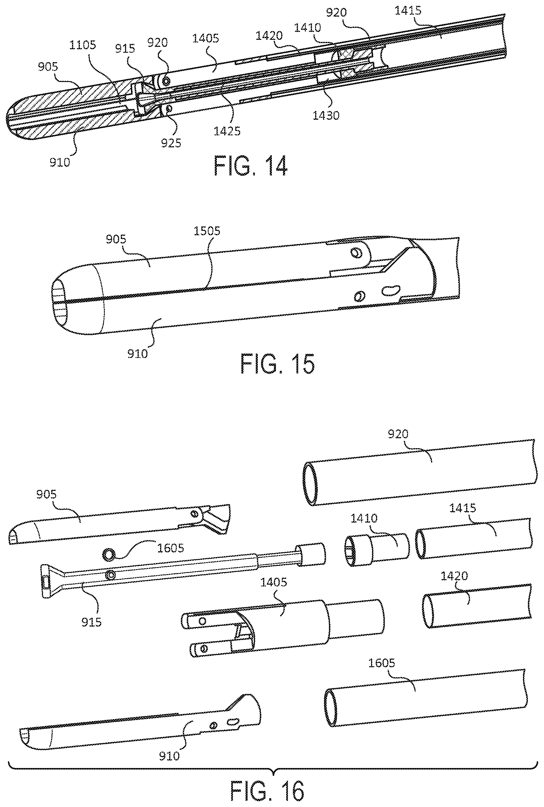
D00013

D00014

D00015

D00016

D00017

D00018

D00019

D00020

D00021

XML
uspto.report is an independent third-party trademark research tool that is not affiliated, endorsed, or sponsored by the United States Patent and Trademark Office (USPTO) or any other governmental organization. The information provided by uspto.report is based on publicly available data at the time of writing and is intended for informational purposes only.
While we strive to provide accurate and up-to-date information, we do not guarantee the accuracy, completeness, reliability, or suitability of the information displayed on this site. The use of this site is at your own risk. Any reliance you place on such information is therefore strictly at your own risk.
All official trademark data, including owner information, should be verified by visiting the official USPTO website at www.uspto.gov. This site is not intended to replace professional legal advice and should not be used as a substitute for consulting with a legal professional who is knowledgeable about trademark law.