Saline Contact With Electrodes
Davison; Mark A. ; et al.
U.S. patent application number 15/720822 was filed with the patent office on 2019-04-04 for saline contact with electrodes. The applicant listed for this patent is Ethicon LLC. Invention is credited to Jeffrey L. Aldridge, Ryan M. Asher, Kevin A. Bash, Jeffrey W. Bullock, Craig T. Davis, Mark A. Davison, Kristen G. Denzinger, Monica L. Rivard, Eric M. Roberson, Mark E. Tebbe, Shan Wan.
| Application Number | 20190099212 15/720822 |
| Document ID | / |
| Family ID | 63857988 |
| Filed Date | 2019-04-04 |


View All Diagrams
| United States Patent Application | 20190099212 |
| Kind Code | A1 |
| Davison; Mark A. ; et al. | April 4, 2019 |
SALINE CONTACT WITH ELECTRODES
Abstract
An end effector of an electrosurgical device may include a discharge port, an aspiration port, two electrodes, and a diverter formed from a porous material. The diverter includes a matrix having voids to receive fluid from the discharge port. A releasable diverter assembly may include an assembly body configured to receive a pair of electrodes and a diverter composed of a porous material. A shaft assembly of an electrosurgical device may include two electrodes and two fluid cannulae. Each cannula may be disposed proximate to a surface of each of the electrodes. An end effector of an electrosurgical device may include a fluid discharge port, two electrodes, and a diverter disposed therebetween. A proximal edge of the diverter may form a secant line with respect to the end of the discharge port so that fluid emitted by the discharge port is disposed on a surface of the diverter.
| Inventors: | Davison; Mark A.; (Maineville, OH) ; Davis; Craig T.; (Cincinnati, OH) ; Bullock; Jeffrey W.; (Madeira, OH) ; Tebbe; Mark E.; (Lebanon, OH) ; Wan; Shan; (Mason, OH) ; Aldridge; Jeffrey L.; (Lebanon, OH) ; Asher; Ryan M.; (Cincinnati, OH) ; Denzinger; Kristen G.; (Cincinnati, OH) ; Rivard; Monica L.; (Cincinnati, OH) ; Bash; Kevin A.; (Cincinnati, OH) ; Roberson; Eric M.; (Lebanon, OH) | ||||||||||
| Applicant: |
|
||||||||||
|---|---|---|---|---|---|---|---|---|---|---|---|
| Family ID: | 63857988 | ||||||||||
| Appl. No.: | 15/720822 | ||||||||||
| Filed: | September 29, 2017 |
| Current U.S. Class: | 1/1 |
| Current CPC Class: | A61B 2218/002 20130101; A61B 2018/00017 20130101; A61B 2018/048 20130101; A61B 2018/00011 20130101; A61B 18/1206 20130101; A61B 2018/00029 20130101; A61B 2018/0063 20130101; A61B 18/12 20130101; A61B 18/148 20130101; A61B 2018/00035 20130101; A61B 2018/00595 20130101; A61B 2218/007 20130101; A61B 18/14 20130101; A61B 2018/126 20130101 |
| International Class: | A61B 18/14 20060101 A61B018/14 |
Claims
1. An end effector of an electrosurgical device, the end effector comprising: a distal fluid discharge port in fluid communication with a first fluid path; a distal fluid aspiration port in fluid communication with a second fluid path; a first electrode and a second electrode; and a diverter disposed between the first electrode and the second electrode, wherein the diverter comprises a porous material having a matrix and a plurality of voids disposed therein, and wherein the plurality of voids is fluidically coupled to the distal fluid discharge port.
2. The end effector of claim 1, wherein the plurality of voids is configured to direct a fluid from the distal fluid discharge port to a surface of the diverter.
3. The end effector of claim 2, wherein the surface of the diverter comprises a top surface of the diverter.
4. The end effector of claim 2, wherein the surface of the diverter comprises one or more side surfaces of the diverter.
5. The end effector of claim 2, wherein the plurality of voids comprises at least one channel.
6. The end effector of claim 5, wherein the at least one channel comprises a channel physically coupled to the distal fluid discharge port.
7. The end effector of claim 5, wherein the at least one channel comprises a first channel configured to direct at least a portion of the fluid to a first side surface of the diverter and a second channel configured to direct at least a portion of the fluid to a second side surface of the diverter.
8. The end effector of claim 1, wherein the matrix comprises a ceramic matrix.
9. The end effector of claim 1, wherein the diverter comprises a releasable diverter assembly.
10. The end effector of claim 1, wherein the distal fluid aspiration port is configured to remove a material from an area proximate to the diverter.
11. A releasable diverter assembly for an electrosurgical device, the assembly comprising: an assembly body comprising a first receptacle configured to receive a first electrode of the electrosurgical device and a second receptacle configured to receive a second electrode of the electrosurgical device; a first electrode contact mounted on the assembly body and proximate to the first receptacle; a second electrode contact mounted on the assembly body and proximate to the second receptacle; a conduit configured to receive a fluid from a fluid source port of the electrosurgical device; and a diverter disposed between the first electrode contact and the second electrode contact, wherein the diverter comprises a porous material having a matrix and a plurality of voids disposed therein, and wherein the plurality of voids is fluidically coupled to the conduit.
12. The releasable diverter assembly of claim 11, wherein the plurality of voids is configured to direct the fluid from the conduit to a surface of the diverter.
13. The releasable diverter assembly of claim 12, wherein the surface of the diverter comprises a top surface of the diverter.
14. A shaft assembly of an electrosurgical device, the shaft assembly comprising: a first electrode and a second electrode; a first fluid cannula having a first distal fluid source port and disposed proximate to an outer surface of the first electrode; a second fluid cannula having a second distal fluid source port and disposed proximate to an outer surface of the second electrode; a distal fluid evacuation port disposed at least in part between the first electrode and the second electrode; and a shaft configured to enclose the first electrode, the second electrode, the first fluid cannula, and the second fluid cannula.
15. The shaft assembly of claim 14, wherein the first electrode comprises a first outer surface groove and the second electrode comprises a second outer surface groove, and wherein the first fluid cannula is disposed within the first outer surface groove and the second fluid cannula is disposed within the second outer surface groove.
16. The shaft assembly of claim 14, further comprising a first insulating cover disposed around the first electrode and the first fluid cannula and a second insulating cover disposed around the second electrode and the second fluid cannula.
17. The shaft assembly of claim 14, further comprising a proximal fluid extraction assembly disposed around a proximal end of the shaft.
18. The shaft assembly of claim 17, wherein the proximal fluid extraction assembly comprises: a proximal fluid extraction port fluidically coupled to the distal fluid evacuation port; and a proximal electrode cap configured to receive a proximal portion of the first electrode, a proximal portion the first fluid cannula, a proximal portion the second electrode, and a proximal portion the second fluid cannula.
19. The shaft assembly of claim 14, further comprising a distal isolation ring disposed within an interior of the shaft at a distal end of the shaft and configured to receive a distal portion of the first electrode, a distal portion the first fluid cannula, a distal portion the second electrode, and a distal portion the second fluid cannula.
20. The shaft assembly of claim 19, wherein the distal fluid evacuation port comprises at least a portion of a surface of the distal isolation ring.
21. An end effector of an electrosurgical device comprising: a distal fluid discharge port in fluid communication with a first fluid path, wherein the distal fluid discharge port comprises a distal orifice; a distal fluid aspiration port in fluid communication with a second fluid path; a first electrode and a second electrode; and a diverter in mechanical communication with the first electrode and the second electrode, and disposed therebetween, wherein the diverter has a first surface comprising a plane parallel to the longitudinal axis of the distal fluid discharge port, wherein a proximal edge of the diverter is adjacent to the distal orifice, and wherein the diverter is configured to receive, on the first surface, at least a portion of a fluid emitted by the distal fluid discharge port, and to maintain a contact of the fluid thereon with a surface of the first electrode and a surface of the second electrode.
22. The end effector of claim 21, wherein the diverter comprises a plurality of features on the first surface.
23. The end effector of claim 22, wherein the plurality of features are configured to direct a flow of the fluid on the first surface of the diverter towards the first electrode or the second electrode.
24. The end effector of claim 22, wherein the plurality of features comprise a plurality of protrusions.
25. The end effector of claim 22, wherein the plurality of features comprise a plurality of recesses.
26. The end effector of claim 21, wherein the proximal edge of the diverter is disposed midway across the distal orifice.
27. The end effector of claim 21, wherein the distal orifice has an elliptical circumference.
28. The end effector of claim 21, wherein the distal orifice has a circular circumference.
29. The end effector of claim 21, wherein the diverter has a second surface, and the second surface comprises a second plurality of features configured to direct a flow of the fluid on the second surface of the diverter towards the first electrode or the second electrode.
Description
BACKGROUND
[0001] Many internal surgical procedures require the removal of tissue as part of the surgical procedure. The removal of such tissue invariably results in severing multiple blood vessels leading to localized blood loss. Significant blood loss may comprise the patient's health by potentially leading to hypovolemic shock. Even minor blood loss may complicate the surgery by resulting in blood pooling into the surgical site, thereby obscuring the visibility of the tissue from the surgeons and surgical assistants. The problem of blood loss into the surgical site may be especially important in broad area surgeries, such as liver resection, in which multiple blood vessels may be severed during the procedure.
[0002] Typically, an electrosurgical cautery device is used to seal the blood vessels, thereby preventing blood loss. Such electrosurgical cautery devices may include bipolar devices that incorporate a pair of electrodes that are powered by RF (radiofrequency) energy to heat and cauterize the tissue and blood vessels. Direct application of the electrodes to the tissue may lead to unwanted effects such as localized tissue charring and fouling of the electrodes by charred tissue matter sticking to them.
[0003] A method to reduce charring and fouling may include introducing a saline fluid into the surgical site to irrigate the site. Alternatively, the saline fluid may be heated by the electrodes to form a steam to cauterize the tissue. In this manner, the tissue is not placed in direct contact with the electrodes and electrode fouling is prevented. Although a saline fluid may be used, any electrically conducting fluid (for example, an aqueous mixture containing ionic salts) may be used to promote steam-based cauterization. After the steam cauterizes the tissue by transferring its heat thereto, the steam may condense to water. The resulting water may be used to clear the surgical site of unwanted material such as the remnants of the cauterized tissue. An aspirator may be used to remove the mixture of water and tissue remnants. It may be difficult and inefficient for the surgeon to cauterize and aspirate the tissue especially if separate devices are required. Thus, a device incorporating the cauterization and aspiration functions is desirable.
[0004] The incorporation of both a saline source and an evacuation source for aspiration into a bipolar electrosurgical cautery instrument may be problematic. If the aspirator operates continuously, then the saline may not reside in contact with the electrodes long enough to be heated and form steam. If the saline source operates continuously, then excess saline may be delivered to the surgical site and obscure the area from the surgeon. It is possible to have a device with multiple actuators to allow the surgeon to selectively emit a fluid to be vaporized by the electrodes and evacuate the surgical site. However, such multiple actuators may be clumsy to use and lead to hand and finger fatigue during a long surgical procedure.
[0005] Therefore, it is desirable to have a device that permits a surgeon to effectively and efficiently provide steam cauterization and tissue mixture aspiration to a surgical site without requiring excessive manipulation of the surgical device.
SUMMARY
[0006] In one aspect, an end effector of an electrosurgical device, may include a distal fluid discharge port in fluid communication with a first fluid path, a distal fluid aspiration port in fluid communication with a second fluid path, a first electrode and a second electrode, and a diverter disposed between the first electrode and the second electrode, in which the diverter includes a porous material having a matrix and a plurality of voids disposed therein, and in which the plurality of voids is fluidically coupled to the distal fluid discharge port.
[0007] In one aspect of an end effector, the plurality of voids is configured to direct a fluid from the distal fluid discharge port to a surface of the diverter.
[0008] In one aspect of an end effector, the surface of the diverter is a top surface of the diverter.
[0009] In one aspect of an end effector, the surface of the diverter includes one or more side surfaces of the diverter.
[0010] In one aspect of an end effector, the plurality of voids includes at least one channel.
[0011] In one aspect of an end effector, the at least one channel includes a channel physically coupled to the distal fluid discharge port.
[0012] In one aspect of an end effector, the at least one channel includes a first channel configured to direct at least a portion of the fluid to a first side surface of the diverter and a second channel configured to direct at least a portion of the fluid to a second side surface of the diverter.
[0013] In one aspect of an end effector, the matrix is a ceramic matrix.
[0014] In one aspect of an end effector, the diverter is composed of a releasable diverter assembly.
[0015] In one aspect of an end effector, the distal fluid aspiration port is configured to remove a material from an area proximate to the diverter.
[0016] In one aspect, a releasable diverter assembly for an electrosurgical device may include an assembly body comprising a first receptacle and a second receptacle. The first receptacle may be configured to receive a first electrode of the electrosurgical device and the second receptacle may be configured to receive a second electrode of the electrosurgical device. The releasable diverter assembly may also include a first electrode contact mounted on the assembly body and proximate to the first receptacle, a second electrode contact mounted on the assembly body and proximate to the second receptacle, a conduit configured to receive a fluid from a fluid source port of the electrosurgical device, and a diverter disposed between the first electrode contact and the second electrode contact. In the aspect of a releasable diverter assembly, the diverter may be composed of a porous material having a matrix and a plurality of voids disposed therein, and the plurality of voids may be fluidically coupled to the conduit.
[0017] In one aspect of the releasable diverter assembly, the plurality of voids is configured to direct the fluid from the conduit to a surface of the diverter.
[0018] In one aspect of the releasable diverter assembly, the surface of the diverter comprises a top surface of the diverter.
[0019] In one aspect, a shaft assembly of an electrosurgical device may include a first electrode and a second electrode, a first fluid cannula having a first distal fluid source port and disposed proximate to an outer surface of the first electrode, a second fluid cannula having a second distal fluid source port and disposed proximate to an outer surface of the second electrode, a distal fluid evacuation port disposed at least in part between the first electrode and the second electrode, and a shaft configured to enclose the first electrode, the second electrode, the first fluid cannula, and the second fluid cannula.
[0020] In one aspect of a shaft assembly, the first electrode has a first outer surface groove and the second electrode has a second outer surface groove, and the first fluid cannula is disposed within the first outer surface groove and the second fluid cannula is disposed within the second outer surface groove.
[0021] An aspect of a shaft assembly may further include a first insulating cover disposed around the first electrode and the first fluid cannula and a second insulating cover disposed around the second electrode and the second fluid cannula.
[0022] An aspect of a shaft assembly may further include a proximal fluid extraction assembly disposed around a proximal end of the shaft.
[0023] In one aspect of a shaft assembly, the proximal fluid extraction assembly may include a proximal fluid extraction port fluidically coupled to the distal fluid evacuation port and a proximal electrode cap configured to receive a proximal portion of the first electrode, a proximal portion the first fluid cannula, a proximal portion the second electrode, and a proximal portion the second fluid cannula.
[0024] An aspect of a shaft assembly may further include a distal isolation ring disposed within an interior of the shaft at a distal end of the shaft and configured to receive a distal portion of the first electrode, a distal portion the first fluid cannula, a distal portion the second electrode, and a distal portion the second fluid cannula.
[0025] In one aspect of a shaft assembly, the distal fluid evacuation port may include at least a portion of a surface of the distal isolation ring.
[0026] An aspect of an end effector of an electrosurgical device my include a distal fluid discharge port having a distal orifice, the distal fluid discharge port also being in fluid communication with a first fluid path, a distal fluid aspiration port in fluid communication with a second fluid path, a first electrode and a second electrode, and a diverter in mechanical communication with the first electrode and the second electrode, and disposed therebetween. Further, the diverter may have a first surface forming a plane parallel to the longitudinal axis of the distal fluid discharge port, and a proximal edge disposed adjacent to the distal orifice. Additionally, the diverter may be configured to receive, on the first surface, at least a portion of a fluid emitted by the distal fluid discharge port, and to maintain a contact of the fluid thereon with a surface of the first electrode and a surface of the second electrode.
[0027] In an aspect of an end effector, the diverter includes a plurality of features on the first surface.
[0028] In an aspect of an end effector, the plurality of features are configured to direct a flow of the fluid on the first surface of the diverter towards the first electrode or the second electrode.
[0029] In an aspect of an end effector, the plurality of features may include a plurality of protrusions.
[0030] In an aspect of an end effector, the plurality of features may include a plurality of recesses.
[0031] In an aspect of an end effector, the proximal edge of the diverter is disposed midway across the distal orifice.
[0032] In an aspect of an end effector, the distal orifice has an elliptical circumference.
[0033] In an aspect of an end effector, the distal orifice has a circular circumference.
[0034] In an aspect of an end effector, the diverter has a second surface, and the second surface has a second plurality of features configured to direct a flow of the fluid on the second surface of the diverter towards the first electrode or the second electrode.
BRIEF DESCRIPTION OF THE FIGURES
[0035] The features of the various aspects are set forth with particularity in the appended claims. The various aspects, however, both as to organization and methods of operation, together with advantages thereof, may best be understood by reference to the following description, taken in conjunction with the accompanying drawings as follows:
[0036] FIG. 1 illustrates a perspective view of one aspect of an electrosurgical device.
[0037] FIG. 2 illustrates an expanded view of one aspect of an end effector of the electrosurgical device depicted in FIG. 1.
[0038] FIG. 3 illustrates a side perspective view of one aspect of the electrosurgical device depicted in FIG. 1.
[0039] FIGS. 4, 5, and 6 illustrate plan views of the bottom, side, and top, respectively, of one aspect of the electrosurgical device depicted in FIG. 1.
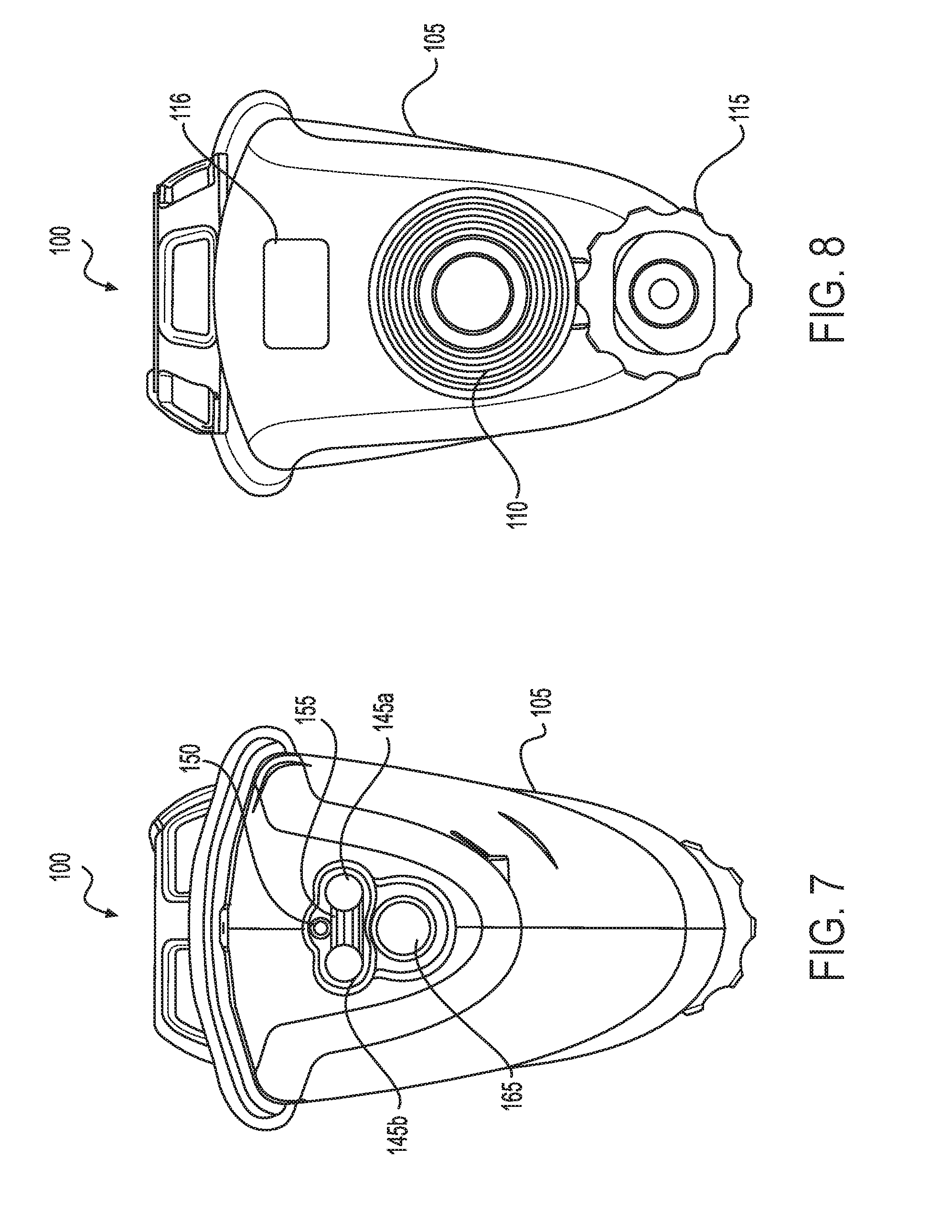
[0040] FIG. 7 illustrates a plan front (distal) view of one aspect of the electrosurgical device depicted in FIG. 1.
[0041] FIG. 8 illustrates a plan rear (proximal) view of one aspect of the electrosurgical device depicted in FIG. 1.
[0042] FIG. 9 illustrates a partial sectional perspective view of one aspect of the electrosurgical device depicted in FIG. 1.
[0043] FIG. 10 illustrates a partial sectional plan front (distal) view of one aspect of the electrosurgical device depicted in FIG. 1.
[0044] FIG. 11 illustrates a perspective view of one aspect of an end effector of the electrosurgical device depicted in FIG. 1.
[0045] FIG. 12 illustrates a perspective view of a model of one aspect of an end effector of the electrosurgical device depicted in FIG. 1.
[0046] FIG. 13 illustrates a perspective view of a first aspect of a pair of electrodes and a diverter of an end effector of an electrosurgical device depicted in FIG. 1.
[0047] FIG. 14 illustrates a top plan view of the first aspect of a pair of electrodes and a diverter depicted in FIG. 13.
[0048] FIG. 15 illustrates a perspective view of a second aspect of a pair of electrodes and a diverter of an end effector of an electrosurgical device depicted in FIG. 1.
[0049] FIG. 16 illustrates a top plan view of the second aspect of a pair of electrodes and a diverter depicted in FIG. 15.
[0050] FIG. 17 illustrates a perspective view of a third aspect of a pair of electrodes and a diverter an end effector of an electrosurgical device depicted in FIG. 1.
[0051] FIG. 18 illustrates a top plan view of the third aspect of a pair of electrodes and a diverter depicted in FIG. 17.
[0052] FIG. 19 illustrates a perspective view of an alternate aspect of the end effector of an electrosurgical device depicted in FIG. 13.
[0053] FIG. 20 illustrates a top plan view of the alternate aspect of the end effector of an electrosurgical device depicted in FIG. 19.
[0054] FIG. 21A illustrates a plan front (distal) view of one aspect of an end effector of an electrosurgical device.
[0055] FIG. 21B illustrates a plan front (distal) view of a second aspect of an end effector of an electrosurgical device.
[0056] FIG. 21C illustrates a side cross-sectional view of an aspect of an end effector of an electrosurgical device.
[0057] FIG. 21D illustrates a top cross-sectional view of an aspect of an end effector of an electrosurgical device.
[0058] FIG. 22A depicts a perspective view of an aspect of an end effector of an electrosurgical device along with an aspect of a releasable diverter assembly.
[0059] FIG. 22B depicts a perspective view of the aspect of an end effector of an electrosurgical device coupled to the aspect of a releasable diverter assembly as depicted in FIG. 22A.
[0060] FIG. 22C depicts a top plan view of multiple aspects of a releasable diverter assembly.
[0061] FIG. 23A depicts a partial assembly view of one aspect of an end effector of an electrosurgical device.
[0062] FIG. 23B depicts a perspective view of a component of the end effector depicted in FIG. 23A.
[0063] FIG. 24 depicts a perspective view of another aspect of an end effector of an electrosurgical device.
[0064] FIGS. 25A and B depict top cross-sectional views of some alternative aspects of the end effector depicted in FIG. 24.
[0065] FIGS. 26A and B depict, in a side cross-section view, an aspect of a method for fabricating a diverter such as depicted in FIGS. 25A and B.
[0066] FIG. 27A and B depict one set of sectional views of the aspect of the diverter as depicted in FIGS. 25A and 25B, respectively.
[0067] FIG. 28A and B depict a second set of sectional views of the aspect of the diverter as depicted in FIGS. 25A and 25B, respectively.
[0068] FIG. 29 depicts a perspective view of another aspect of an end effector of an electrosurgical device.
[0069] FIG. 30A depicts an assembly view of a portion of the end effector depicted in FIG. 29.
[0070] FIG. 30B depicts an interior view of an aspect of a diverter.
[0071] FIG. 31 depicts a perspective view of an aspect of a shaft assembly for use with an electrosurgical device.
[0072] FIG. 32 is a transparent perspective view of the aspect of the shaft assembly depicted in FIG. 31.
[0073] FIG. 33A is a perspective view of an aspect of an end effector of the shaft assembly depicted in FIG. 31.
[0074] FIG. 33B is a front (distal end) plan view of the aspect of the end effector depicted in FIG. 33A.
[0075] FIG. 33C is a side plan view of the aspect of the end effector depicted in FIG. 33A.
[0076] FIG. 34A is a transparent perspective view of an aspect of a proximal fluid extraction assembly component of the shaft assembly depicted in FIG. 31.
[0077] FIG. 34B is a perspective side sectional view of the aspect of the proximal fluid extraction assembly depicted in FIG. 34A.
[0078] FIG. 34C is a side cross-sectional view of the aspect of the proximal fluid extraction assembly depicted in FIG. 34A.
DETAILED DESCRIPTION
[0079] Applicant of the present application owns the following patent applications filed concurrently herewith and which are each herein incorporated by reference in their respective entireties:
[0080] Attorney Docket No. END8256USNP/170167, titled BIPOLAR ELECTRODE SALINE LINKED CLOSED LOOP MODULATED VACUUM SYSTEM, by inventors David A. Witt et al., filed on even date herewith.
[0081] Attorney Docket No. END8258USNP/170169, titled SYSTEMS AND METHODS FOR MANAGING FLUID AND SUCTION IN ELECTROSURGICAL SYSTEMS, by inventors David A. Witt et al., filed on even date herewith.
[0082] Attorney Docket No. END8259USNP/170170, titled FLEXIBLE ELECTROSURGICAL INSTRUMENT, by inventors David A. Witt et al., filed on even date herewith.
[0083] As disclosed above, an electrosurgical device may incorporate functions to cauterize and aspirate tissues during a broad area surgical procedure. In some electrosurgical devices, energized electrodes may be used to perform the cauterization procedure. However, as also disclosed above, the electrodes of such devices may be susceptible to fouling by the tissue contacted by the electrodes during cauterization. It may be appreciated that cauterization of tissue may be accomplished by exposing the tissue to a heated material other than the electrodes. As also disclosed above, in one non-limiting example, a fluid, such as a saline fluid, may be heated by the electrodes and the heated fluid or steam may then be used to cauterize the tissue. The saline, or other conductive fluid, may be heated by an electrical current flowing between the electrodes. In this manner, the temperature used to cauterize the tissue may be limited by the temperature of the steam (for example, at around 100.degree. C.) thereby reducing the potential of tissue charring. Further, the surrounding tissue may be moistened by the steam, thereby preventing desiccation due to their proximity to a heated device. Additionally, the steam, upon losing heat by contacting the tissue, may condense to water, and the water may then be used to irrigate the surgical site. In this manner, a saline fluid may be used for the dual purposes of cauterization and irrigation, thereby increasing the efficiency of the cauterization procedure.
[0084] FIGS. 1-8 depict views of one example of such an electrosurgical device 100. For FIGS. 1-8, common reference numbers refer to common components within the figures.
[0085] The electrosurgical device 100 may include a housing 105 with a shaft 135 extending distally from the housing 105. The housing 105 may include, on a proximal end, a proximal fluid source port 115 and a proximal fluid evacuation port 110. In some electrosurgical device systems, the proximal fluid source port 115 may be placed in fluid communication with a source of a fluid, for example saline, buffered saline, Ringer's solution, or other electrically conducting fluids such as aqueous fluids containing ionic salts. The fluid source may operate as a gravity feed source or it may include components to actively pump the fluid into the proximal fluid source port 115. An actively pumping fluid source may include, without limitation, a power supply, a pump, a fluid source, and control electronics to allow a user to actively control the pumping operation of the actively pumping fluid source. In some electrosurgical device systems, the fluid evacuation port 110 may be placed in fluid communication with a vacuum source. The vacuum source may include a power supply, a pump, a storage component to store material removed by the vacuum source, and control electronics to allow a user to actively control the pumping operation of the vacuum source.
[0086] In addition, the housing 105 may include a connector 116 to which a cable 117 of an energy source 120 may be attached. The energy source 120 may be configured to supply energy (for example RF or radiofrequency energy) to the electrodes 145a,b. The energy source 120 may include a generator configured to supply power to the electrosurgical device 100 through external means, such as through the cable 117. In certain instances, the energy source 120 may include a microcontroller coupled to an external wired generator. The external generator may be powered by AC mains. The electrical and electronic circuit elements associated with the energy source 120 may be supported by a control circuit board assembly, for example. The microcontroller may generally comprise a memory and a microprocessor ("processor") operationally coupled to the memory. The electronic portion of the energy source 120 may be configured to control transmission of energy to electrodes 145a,b at the end effector 140 of the electrosurgical device 100. It should be understood that the term processor as used herein includes any suitable microprocessor, microcontroller, or other basic computing device that incorporates the functions of a computer's central processing unit (CPU) on an integrated circuit or at most a few integrated circuits. The processor may be a multipurpose, programmable device that accepts digital data as input, processes it according to instructions stored in its memory, and provides results as output. It is an example of sequential digital logic, as it has internal memory. Processors operate on numbers and symbols represented in the binary numeral system. The energy source 120 may also include input devices to allow a user to program the operation of the energy source 120.
[0087] The housing 105 may also include one or more activation devices to permit a user to control the functions of the electrosurgical device 100. In some non-limiting example, the electrosurgical device 100 may include a metering valve 125 that may be activated by a user to control an amount of fluid flowing through the electrosurgical device and provide, at the distal end, an amount of the fluid to the end effector 140. In some non-limiting examples, the metering valve 125 may also permit the user to control an amount of energy supplied by the energy source 120 to the electrodes 145a,b at the end effector 140. As an example, the metering valve 125 may comprise a screw activation pinch valve to regulate the flow of fluid through the electrosurgical device 100. Additionally, the metering valve 125 may have a push-button activation function to permit current to flow from the energy source 120 to the electrodes 145a,b upon depression of the push-button by a user. It may be recognized that in some non-limiting examples, the housing 105 may include a metering valve 125 to allow regulation of fluid flow through the electrosurgical device 100 and a separate energy control device to control the amount of current sourced to the electrodes 145a,b.
[0088] The housing 105 may also be attached to a shaft 135 at a distal end of the housing 105. An end effector 140 may be associated with a distal end of the shaft 135. The end effector 140 may include electrodes 145a,b that may be in electrical communication with the energy source 120 and may receive electrical power therefrom. In some non-limiting examples, a first electrode 145a may receive electrical energy of a first polarity (such as a positive polarity) from the energy supply 120 and the second electrode 145b may receive electrical energy of a second and opposing polarity (such as a negative polarity) from the energy supply 120. Alternatively, the first electrode 145a may be connected to a ground terminal of the energy supply 120, and the second electrode 145b may be connected to a varying AC voltage terminal of the energy supply 120. The electrodes 145a,b may extend beyond the distal end of the shaft 135. The extended ends of the electrodes 145a,b be separated by a diverter 155. The diverter 155 may contact the first electrode 145a at a first edge of the diverter 155, and the diverter 155 may contact the second electrode 145b at a second edge of the diverter 155. The diverter 155 may comprise an electrically insulating material and/or a heat resistant material, which may include, without limitation a plastic such as a polycarbonate or a ceramic. The diverter 155 may be deformable or non-deformable. In some non-limiting examples, the housing 105 may include a mechanism to control a shape of a deformable diverter 155.
[0089] The end effector 140 may also include a fluid discharge port 150 that may be in fluid communication with the fluid source port 115 through a first fluid path. The first fluid path, such as a source fluid path (see 315 in FIG. 11), may permit the fluid to flow from the fluid source port 115 to the fluid discharge port 150. In some non-limiting examples, the fluid discharge port 150 may be positioned above the diverter 155 so that a fluid emitted by the fluid discharge port 150 may be collected on a top surface of the diverter 155. The end effector may also include a fluid aspiration port 165 that may be in fluid communication with the fluid evacuation port 110 through a second fluid path. The second fluid path, such as an aspirated fluid path (see 210 in FIG. 9), may permit a liquid mixture generated at the surgical site to flow from the fluid aspiration port 165 to the fluid evacuation port 110. The liquid mixture may then be removed from the electrosurgical device 100 by the vacuum source and stored in the storage component for later removal.
[0090] In some non-limiting examples, the fluid aspiration port 165 may be formed at the distal end of an aspiration tube 160. The aspiration tube 160 may also form part of the aspirated fluid path 210. The aspiration tube 160 may be located within the shaft 135 or it may be located outside of and beneath the shaft 135. An aspiration tube 160 located outside of the shaft 135 may be in physical communication with an external surface of the shaft 135. In some examples, the aspiration tube 160 may have a fixed location with respect to the shaft 135. In some alternative examples, the aspiration tube 160 may be extendable in a distal direction with respect to the shaft 135. Extension of the extendable aspiration tube 160 may be controlled by means of an aspiration tube control device. As one non-limiting example, the aspiration tube control device may comprise a slide switch 130. The slide switch 130, in a first position (for example, in a proximal position), may cause the aspiration tube 160 to remain in a first or retracted position in which the aspiration port 165 is located essentially below the fluid discharge port 150. However, the slide switch 130 in a second position (for example in a distal position), may cause the aspiration tube 160 to extend in a distal direction to a fully extended position so that the aspiration port 165 is located distal from and beneath the fluid discharge port 150. In one example, the slide switch 130 may preferentially position the aspiration tube 160 in one of two positions, such as the retracted position and the fully extended position. It may be recognized, however, that the slide switch 130 may also permit the aspiration tube 160 to assume any position between the retracted position and the fully extended position. Regardless of the position of the aspiration tube 160 as disclosed above, the aspiration port 165 may be maintained at a location beneath a plane defined by the top surface of the diverter 155. In this manner, the diverter 155 is configured to prevent fluid emitted by the fluid discharge port 150 from directly being removed at the aspiration port 165.
[0091] FIGS. 9 and 10 present partial interior views of an electrosurgical device 200. In addition to the components disclosed above with respect to FIGS. 1-8, the electrosurgical device 200 includes an aspirated fluid path 210 that forms a fluid connection between the proximal fluid evacuation port 110 and the distal fluid aspiration port 165. Also illustrated are valve components 225 of the metering valve 125 and control components 230 of the aspiration tube such as, for example, a slide switch 130. Fluid discharge port 150, electrodes 145a,b, fluid aspiration port 165, and a portion of housing 105 are also illustrated in FIGS. 9 and 10.
[0092] FIG. 11 presents a perspective view of a general example of an end effector 600. As disclosed above, the end effector may be composed of a pair of electrodes 145a,b, extending from a shaft 135, a distal fluid discharge port 150, a diverter 155, and an aspiration port 165 that may be part of an aspiration tube 160. The diverter 155 may be placed between the pair of electrodes 145a,b in such a manner as to form a contact of a first edge of the diverter 155 with a surface of one electrode 145a, and a contact of a second edge of the diverter 155 with a surface on a second electrode 145b. In some examples, a proximal edge of the diverter 155 may form a mechanical communication with an end surface of the shaft 135. In this manner, fluid emitted by the distal fluid discharge port 150 may be retained on a first or top surface of the diverter 155. The fluid on the top surface of the diverter 155 may be retained on that surface for a sufficient time to maintain contact of the fluid with a surface of both electrodes 145a,b. If the fluid is an ionic fluid, current passing through the fluid between the electrodes 145a,b may heat the fluid sufficiently to form a steam capable of cauterizing tissue.
[0093] FIG. 12 depicts a perspective view of a fabricated model of the end effector 600 as depicted in FIG. 11.
[0094] FIGS. 13-20 depict a variety of examples of an end effector as generally disclosed as end effector 600 depicted in FIG. 11.
[0095] FIGS. 13 and 14 illustrate a perspective view and a top plan view, respectively, of one example of end effector 700. End effector 700 illustrates many of the components disclosed above with respect to end effector 600 of FIG. 11. These components include the shaft 135, the fluid discharge port 150, the aspirator port 165, the electrodes 145a,b, and aspirator tube 160. In addition to the aspirator port 165, the aspirator tube 160 may include additional ports along the length of the aspirator tube 160 to aspirate material from the surgical site. The diverter 755 of end effector 700 includes a number of features 757a configured to direct the flow of a fluid emitted by fluid discharge port 150 to the surface of electrodes 145a,b. Features 757a may include curved guide-ways protruding from the top surface of the diverter 755. Additionally, the top surface of the diverter 755 may include additional features at the distal end to further guide the fluid towards the electrodes 145a,b. The electrodes 145a,b may have a generally circular or elliptical cross section 745a,b at a portion near the distal end of the shaft 135. Further, the electrodes 145a,b may be chamfered at their distal ends 747a,b resulting in an oval or egg-shaped distal end 747a,b. Cross-sectional view F in FIG. 14 illustrates that the oval distal ends 747a,b of the electrodes 145a,b have their respective long axes directed to the outer portion of the end effector 700, away from the diverter 755.
[0096] FIGS. 15 and 16 illustrate a perspective view and a top plan view, respectively, of another example of end effector 700. In FIGS. 15 and 16, the distal portion of the electrodes 145a,b may have a circular or oval cross section, but the electrodes 145a,b may have a fabiform or kidney-shaped cross section 745c,d closer (proximal) to the shaft 135. Such a fabiform cross section 745c,d may be useful during fabrication of the electrosurgical device to secure the diverter 755 between the inner surfaces of the electrodes 145a,b. Cross sectional view G of FIG. 16 illustrates how the diverter 755 may be secured against the inner surfaces of the fabiform cross section 745c,d. The example of end effector 700 depicted in FIGS. 15 and 16 also are distinguished from that depicted in FIGS. 13 and 14 in that the features 757b comprising the protruding fluid guide-ways comprise straight guide-ways to direct the fluid on the top surface of the diverter 755 to the electrodes 145a,b. Additionally, the electrodes 145a,b may be chamfered to result in oval distal ends 747c,d in which the respective long axes 749a,b are directed towards the inner portion of the end effector 700, and pointing towards the diverter 755. This geometry is depicted in FIG. 16, cross-sectional view H.
[0097] FIGS. 17 and 18 illustrate a perspective view and a top plan view, respectively, of yet another example of end effector 700. The end effector 700 depicted in FIGS. 17 and 18 shows common elements to those of examples illustrated in FIGS. 13-16. Thus, the electrodes 145a,b have a circular or elliptical cross section 745a,b as illustrated in FIGS. 13 and 14 but include the oval cross sections 747c,d at the distal ends of the electrodes 145a,b as depicted in FIGS. 15 and 16. The fluid flow features 757c illustrated in FIGS. 17 and 18 are fabricated as recesses in the surface of the diverter 756. Such recess features 757c may form channels that may be used to guide the flow of a fluid on the top surface of the diverter 756 as suggested by the arrows shown in FIG. 18. The recess FIGS. 757c may also specifically guide a flow of the fluid against the inner surfaces of electrodes 145a,b as also illustrated in FIG. 18. The features 757c may also include a spill-way to direct the fluid emitted by the fluid discharge port 150 towards the channels in the surface of diverter 756 thereby preventing the fluid from flowing out of the recesses when the fluid initially leaves the fluid discharge port 150.
[0098] FIGS. 19 and 20 illustrate a perspective view and a top plan view, respectively, of still another example of end effector 700. The electrodes 145a,b, shaft 135, the fluid discharge port 150, the aspirator port 165, and aspirator tube 160 are all similar to the examples depicted in FIG. 13. Additionally, a portion of the source fluid path 315 proximal to the fluid discharge port 150 may include features such as rifling 750 on the inner surface of the source fluid path 315. Such rifling 750 may impart a turbulent flow to a fluid emitted by the fluid discharge port 150, especially if the fluid is sourced under pressure. Thus, a fluid entering the distal end of source fluid path 315 (arrow on right of FIG. 44) may exit at the fluid discharge port 150 having a turbulent flow that is more easily distributed by the features 757a on the top surface of diverter 755, as illustrated by the arrows superimposed on the top surface of diverter 755 in FIG. 20. As a result, the fluid on the top surface of diverter 755 may more readily flow to contact the electrodes 145a,b.
[0099] As disclosed above, a fluid, such as a saline fluid, may be heated by a pair of electrodes of an electrosurgical device and the heated fluid or steam may then be used to cauterize the tissue. Aspects of an electrosurgical device may include, for example, a diverter disposed between a pair of electrodes and configured to deliver a fluid from a fluid discharge port to the electrodes (exemplary aspects of such a configuration may be found in FIGS. 11-19 and the accompanying disclosure, above). The fluid from the fluid discharge port may flow onto a surface of the diverter based on a gravity feed mechanism. When the end effector is positioned so that the diverter is roughly normal to the gravitational field, the fluid may flow onto a top surface of the diverter and spread to contact both electrodes. It may be appreciated, however, that tilting the end effector by a user may result in the fluid pooling towards one electrode or the other (a roll rotation), or even avoiding contact with both electrodes (a pitch rotation). Therefore, it may be desirable to have an aspect of an electrosurgical device that permits fluid contact with both electrodes of the electrosurgical device regardless of the orientation of the end effector.
[0100] FIGS. 21A and 21B depict distal end views of aspects of an end effector 800a,b of an electrosurgical device that may overcome orientation dependent fluid flow on a diverter. The diverters depicted in FIGS. FIGS. 13-20 are disposed between the electrodes 145a,b and prevent fluid flow from the fluid discharge port 150 directly to the aspirator port 165. Thus, the diverters depicted in FIGS. 13-20 are disposed beneath a distal orifice of the fluid discharge port 150. The diverters 155 depicted in FIGS. 21A and 21B, may have a top surface defined by a plane parallel to a longitudinal axis of the distal fluid discharge port 150, and may be disposed so that a proximal edge 2155a,b of each diverter 155 is disposed adjacent to a distal orifice 2150a,b of the fluid discharge port 150. In this manner, a first portion of the circumference of the distal orifice 2150a,b may extend above the top surface of the diverters 155 and a second portion of the circumference of the distal orifice 2150a,b may extend below a bottom surface of the diverters 155. When the end effector is oriented so that an aspirator port 2165a,b is disposed below a bottom surface of the diverter 155, at least a portion of the fluid from the fluid discharge port 150 will flow onto the top surface of the diverter 155 and be directed to the electrodes 145a,b. However, if the end effector is inverted (so that the aspirator port 2165a,b is above the diverter 155), at least some portion of the fluid from the fluid discharge port 150 will flow onto the bottom surface of the diverter 155 and be directed to the electrodes 145a,b.
[0101] It may be understood that the diverters 155 depicted in FIGS. 21A and 21B may also incorporate surface features, such as those disclosed above with respect to FIGS. 13-20. Such surface features may operate to direct fluid flow across the top surface of the diverters 155 to contact at least a portion of a surface of each electrode 145a,b. Because it may be anticipated that the electrosurgical device may be oriented so that the aspirator port 2165a,b is above the diverter 155, the bottom surface of the diverter 155 may also include such surface features as depicted in FIGS. 13-20 for a similar purpose.
[0102] In some aspects, the diverter 155 may be disposed so that the proximal edge 2155a is located approximately midway across the distal orifice 2150a. In other aspects, the diverter 155 may be disposed so that the proximal edge 2155b is located either above or below a midline of the distal orifice 2150b. In some aspects, the distal orifice 2150a may have a circular circumference. In other aspects, the distal orifice 2150b may have an elliptical circumference. It may also be understood that an orifice defining an output edge of the aspirator port 2165a,b may not be limited to having a circular circumference, but may have any shaped circumference as may be suitable for the purpose of receiving fluids and other materials from the surgical site.
[0103] FIGS. 21C and 21D depict a side cross-sectional view and a top cross-sectional view, respectively, of either aspect of an end effector 800a,b as depicted in FIGS. 21A and 21B. It may be observed that the fluid discharge port 150 may be in fluid communication with a source fluid path 315 (indicated by the arrow pointing left, towards the distal end of the end effector). Further, the aspirator port 2165a,b may be in fluid communication with an aspirated fluid path 210 (indicated by the arrow pointing right, towards the proximal end of the end effector).
[0104] FIGS. 22A through 22C depict another aspect of an end effector for an electrosurgical device configured to direct fluids to the electrodes regardless of the orientation of the end effector. As depicted in FIG. 22A, the end effector may comprise a distal portion 2240 of the electrosurgical device along with a releasable diverter assembly 2260.
[0105] The distal portion 2240 may include a shaft 135 housing a pair of electrodes 145a,b, a distal fluid discharge port 150, and an aspirator port 165. The distal fluid discharge port 150 may be in fluid communication with a source fluid path 315, and the aspirator port 165 may be in fluid communication with an aspirated fluid path 210. The electrodes 145a,b may be configured to receive RF power in order to cauterize tissue contacting them. In some aspects, the distal portion 2240 depicted in FIG. 22A may represent an end effector of an electrosurgical device lacking a diverter (for example 155). As disclosed above, a diverter suitably placed between electrodes (for example 145a,b) may function to direct a fluid to the electrodes, thereby providing a cauterizing steam to the tissues. Additionally, such a diverter may also prevent fluid flowing from a distal fluid discharge port 150 from being directly removed from the surgical site by the aspirator port 165. A releasable diverter assembly 2260 may be used to adapt an electrosurgical device having a distal portion 2240 to include a diverter.
[0106] An aspect of a releasable diverter assembly 2260 is depicted separately from the distal portion 2240 in FIG. 22A. The releasable diverter assembly 2260 may include an assembly body 2265. In some aspects, the assembly body 2265 may be made of an electrically insulative material. The assembly body 2265 may include two receptacles 2245a,b wherein a first receptacle 2245a may be configured to receive a first electrode 145a and a second receptacle 2245b may be configured to receive a second electrode 145b. The assembly body 2265 may also include a diverter 2255. The diverter 2255 may be physically coupled to a first electrode contact 2247a on a first side and physically coupled to a second electrode contact 2247b on a second side. When the releasable diverter assembly 2260 is releasably attached to the distal portion 2240, a surface of the first electrode 145a may be electrically coupled to the first electrode contact 2247a and a surface of the second electrode 145b may be electrically coupled to the second electrode contact 2247b. In one aspect, the diverter 2255 may comprise one of the diverters depicted in FIGS. 11-19 and disclosed above. In such an aspect, the releasable diverter assembly 2260 may include a conduit 2250 configured to conduct a fluid from the distal fluid discharge port 150 to a top surface of the diverter 2255.
[0107] In an alternative aspect, the diverter 2255 may be composed of a porous material. For the purpose of this disclosure, a porous material may be defined as a material composed of a solid matrix having a plurality of voids dispersed therein. The matrix may be a rigid material or a flexible material. In one example, the matrix may be composed of a heat-resistant ceramic material. In some examples, the voids may include a plurality of pores dispersed throughout the matrix and configured to conduct a fluid from an interior portion of the material to any exterior portion of the material. In some alternative examples, the voids may include one or more channels configured to direct a fluid through the matrix to one or more specifically designed destinations, which may include, without limitation, a top surface of the material, one or more side surfaces of the material, and/or a bottom surface of the material. In some additional examples, the voids may include a mixture of pores and channels as disclosed above. In such an aspect, the releasable diverter assembly 2260 may include a conduit 2250 configured to conduct a fluid from the distal fluid discharge port 150 to an interior portion of the diverter 2225.
[0108] FIG. 22B depicts a view of an end effector 2270 composed of a combination of the distal portion 2240 and the releasable diverter assembly 2260. In some aspects, the releasable diverter assembly 2260 may be slidably associated with the electrodes 145a,b of the distal portion 2240. In some examples, the releasable diverter assembly 2260 may be releasably affixed to the distal portion 2240 through frictional forces of the electrodes 145a,b against the receptacles 2245a,b. In other examples, the releasable diverter assembly 2260 may be releasably affixed to the distal portion 2240 by means of tabs 2236 that may mate with cut-outs 2235 formed in a distal portion of the shaft 135 of the distal portion 2240.
[0109] FIG. 22B further depicts a use of the end effector 2270 during a surgical procedure. Fluid from a fluid source may flow through a source fluid path to the fluid discharge port 150. A conduit 2250 incorporated into the assembly body 2265 of the releasable diverter assembly 2260 may direct the fluid to an interior portion of the diverter 2255. In one example, the plurality of voids in the diverter 2255 may direct the fluid so that the fluid is expressed on a surface of the diverter 2255 as a number of fluid droplets 2290. The fluid droplets 2290 may then cover the surface of the diverter 2255 and contact the electrodes 145a,b of the electrosurgical device.
[0110] In the aspect depicted in FIGS. 22A and 22B, it may be understood that the fluid may cover the surface of the diverter 2255 and contact the electrodes 145a,b regardless of the orientation of the end effector 2270. Without being bound by theory, it may be recognized that a combination of fluid pressure at the fluid source along with capillary action of the fluid through the network of voids within the diverter 2255 may cause the fluid to be expressed on the surface of the diverter 2255 regardless of orientation of the diverter 2255. As a result, the surface of the diverter 2255 may be coated with the fluid which may then contact both electrodes 145a,b of the electrosurgical device.
[0111] FIG. 22C illustrates a number of individual releasable diverter assemblies 2260. Each releasable diverter assembly 2260 may include an assembly body 2265, a pair of electrode contact 2247a,b, a conduit 2250, and a diverter 2255. In some aspects, a group of releasable diverter assemblies 2260 may have identical diverter characteristics including, without limitation, a diverter length, a diverter thickness, a number and/or types of diverter surface features, a type of diverter matrix material, and types and/or disposition of the voids within the matrix. In alternative aspects, releasable diverter assemblies 2260 may differ in any one or more of such characteristics.
[0112] A user of an electrosurgical device that may be used with a releasable diverter assembly 2260 such as depicted in FIG. 22C may choose a releasable diverter assembly 2260 consistent with a surgical need. Thus, in some circumstances, it may be preferable to use a releasable diverter assembly having a solid diverter composed of one or more surface features, including, without limitations, recesses and/or protrusions on the surface, as for example, depicted in FIGS. 13-20. In some circumstance, it may be preferable to use a releasable diverter assembly having a solid diverter having a top surface defined by a plane parallel to a longitudinal axis of a distal fluid discharge port, and which may be disposed so that a proximal edge of the diverter is disposed adjacent to a distal orifice of the fluid discharge port, as depicted in FIGS. 21A,B. In some alternative circumstances, it may be preferable to use a releasable diverter assembly that may be composed of a porous diverter in which the voids are composed of a plurality of pores. In some alternative circumstances, it may be preferable to use a releasable diverter assembly that may be composed of a porous diverter in which the voids are composed of a plurality of channels.
[0113] A releasable diverter assembly may be chosen base on a length of the assembly body. For example, a length of the assembly body may be chosen to permit the tissue to be exposed to a longer or shorter extent of the electrodes. A similar effect may be realized based on a position of the cut-out on the assembly body. Thus, the position of some cut-outs may result in a longer extent of the assembly body being affixed to the distal portion of the electrosurgical device, thereby exposing a longer extent of the electrodes. Alternatively, some cut-outs may result in a shorter extent of the assembly body being affixed to the distal portion of the electrosurgical device, thereby exposing a shorter extent of the electrodes. It may be recognized that a releasable diverter assembly may include multiple cut-outs, thereby permitting the releasable diverter assembly to be affixed to the distal portion of the electrosurgical device at any number of positions along the distal portion.
[0114] A releasable diverter assembly may be chosen based on the amount of fluid that the releasable diverter assembly may be able to source into the surgical site. The amount of fluid that the releasable diverter assembly may be able to source into the surgical site may be based, at least in part, on one or more of the size of the conduit, the number of pores and/or channels within the releasable diverter assembly, and the size of the pores and/or channels within the releasable diverter assembly.
[0115] FIGS. 23A and 23B illustrate another aspect of a porous diverter for use with an electrosurgical device. Depicted in FIG. 23A is an end effector 2300 of an electrosurgical device composed of a pair of electrodes 2345a,b and a diverter 2355. The diverter 2355 is configured to receive a fluid (arrows) through a source fluid path 315. As depicted in FIG. 23A, the source fluid path 315 may be directly and fluidically coupled to the diverter 2355. The diverter 2355 may be composed of an upper portion 2356 and a lower portion 2357. As illustrated in both FIG. 23A and FIG. 23B, the lower portion 2357 may be formed from a porous material in which channels 2359 are fabricated. Such channels 2359 may be fabricated to direct a flow of fluid from the source fluid path 315 through the lower portion 2357 to the sides of the diverter 2355 so that the fluid contacts the electrodes 2345a,b. In one aspect, the upper portion 2356 of the diverter 2355 may form a non-porous cap over the lower portion 2357, thereby preventing a flow of the fluid to a top surface of the diverter 2355. In some alternative aspects, the upper portion 2356 may be a porous surface which may allow at least a portion of the fluid to seep onto, and thereby cover, the top surface of the diverter 2355.
[0116] It may be understood that channels fabricated into at least a portion of a diverter may differ from those depicted in FIGS. 23A and 23B. FIGS. 24-25 depict alternative channels that may be fabricated in a diverter to direct a flow of a fluid to electrodes disposed on opposing sides of a diverter.
[0117] FIG. 24, for example, illustrates a perspective view of an end effector 2400 of an electrosurgical device depicting a diverter 2455 having channels 2459a,b fabricated therein to direct a flow of a fluid (arrows) to a pair of electrodes 145a,b disposed on opposing sides of the diverter 2455. In an aspect of the diverter 2455, a first channel 2459a may be configured to direct a fluid to a first electrode 145a and a second channel 2459b may be configured to direct a fluid to a second electrode 145a For the purpose of illustration, the diverter 2455 in FIG. 24 is shown in a transparent perspective view, thereby showing a view of the two channels 2359a,b and the fluid flow (arrows) that are disposed within an internal portion of the diverter 2455.
[0118] In the view depicted in FIG. 24, the shaft 135 covers the source fluid path to the two channels 2459a,b. FIGS. 25A and 25B are top plan cross-sectional views of aspects of the diverter 2455 depicted in FIG. 24 and depict alternative fluid paths to the diverter. FIG. 25A, for example, depicts an electrosurgical device in which two source fluid paths 2515a and 2515b deliver fluid to the channels 2559a and 2559b, respectively. Specifically, a first source fluid path 2515a directs fluid to a first channel 2559a having multiple fluid discharge ports 2550a configured to deliver the fluid to a surface of a first electrode 145a. Similarly, a second source fluid path 2515b directs fluid to a second channel 2559b having multiple fluid discharge ports 2550b configured to deliver the fluid to a surface of a second electrode 145b. A single aspirated fluid path 210 is also illustrated in the shaft 135 of the electrosurgical device.
[0119] FIG. 25B, depicts an alternative example of an electrosurgical device in which a single source fluid path 2515 delivers fluid to the two channels 2559c,d which are fluidically coupled at a t- or y-connector. Thus, the single source fluid path 2515 directs fluid to both a first channel 2559c having multiple fluid discharge ports 2550c configured to deliver the fluid to a surface of a first electrode 145a a well as to a second channel 2559d having multiple fluid discharge ports 2550d configured to deliver the fluid to a surface of a second electrode 145b. Similarly to the depiction in FIG. 25A, FIG. 25B illustrates a single aspirated fluid path 210 disposed within the shaft 135 of the electrosurgical device.
[0120] FIGS. 26A and 26B depict one aspect of a method of fabricating a diverter 2655 that incorporates one or more channels (for example, 2559a,b) within an interior of the diverter 2655. The diverter 2655 may be formed from two components, a top diverter component 2656a and a bottom diverter component 2656b. The top diverter component 2656a may include one or more depressions 2659a fabricated on a bottom surface of the top diverter component 2656a. Similarly, the bottom diverter component 2656b may include one or more depressions 2659b fabricated on a top surface of the bottom diverter component 2656b. When the top diverter component 2656a is assembled with the bottom diverter component 2656b (as depicted by the arrow from FIG. 26A to FIG. 26B), the depressions 2659a,b may be mated together to form the channels 2559a,b. The depressions 2659a,b may be fabricated according to any appropriate method as known in the art. In one example of a fabrication method, the depressions 2659a and 2659b may be fabricated as part of a molding process of the top diverter component 2656a and the bottom diverter component 2656b, respectively. In another example of a fabrication method, the depressions 2659a and 2659b may be milled into the top diverter component 2656a and the bottom diverter component 2656b, respectively. The top diverter component 2656a and the bottom divert component 2656b may be sealed together according to any method appropriate for the materials used in the top diverter component 2656a and the bottom divert component 2656b.
[0121] FIGS. 27A,B and 28A,B present cross sectional views of diverters 2555a and 2555b as illustrated in FIGS. 25A and 25B, respectively. FIG. 27A depicts the cross section of diverter 2555a illustrating the two source fluid paths 2515a,b and FIG. 27B depicts the cross section of diverter 2555b illustrating the single source fluid path 2515. FIG. 28A depicts the cross section of diverter 2555a illustrating two fluid channels 2550a,b and FIG. 28B depicts the cross section of diverter 2555b illustrating two fluid channels 2550c,d. Additionally, FIGS. 28A and 28B depict alternative aspects of the fluid channels 2559a,b,c,d. Specifically, FIGS. 28A illustrates that fluid channels 2559a,b may have an angled interior while FIGS. 28B illustrates that fluid channels 2559c,d may have a rounded interior.
[0122] It may be recognized that fluid channels disposed within a diverter may have any cross-sectional shape as may be required for their functions. In some aspects, a fluid channel disposed within a diverter may have the same cross-sectional shape along the length of the channel. In other aspects, the cross-sectional shape along a fluid channel disposed within a diverter may vary along the length of the fluid channel. A fluid channel may have a constant diameter along its length within the diverter or a fluid channel may have a varying diameter along its length within the diverter. In some aspects, a single fluid channel disposed within a diverter may be configured to deliver fluid to a surface of each electrode. In some aspects, multiple fluid channels disposed within a diverter may be configured to deliver fluid to a surface of each electrode. FIGS. 29 and 30A,B depict additional aspects of diverters having a multiplicity of fluid channels for delivering a fluid to surfaces of one or more electrodes or to a surface of a diverter.
[0123] FIG. 29 depicts an end effector composed of a diverter 2955 disposed between two electrodes 145a,b. The diverter 2955 is fluidically coupled to a source fluid path 315 that is disposed within a shaft 135 and which supplies a fluid to the diverter 2955. The diverter 2955 may include a plurality of pores 2956 on a surface that are configured to direct the fluid, as a stream or droplets 2990, onto the surface of the diverter 2955 and to contact a surface of each of the electrodes 145a,b.
[0124] FIGS. 30A and 30B illustrate additional views of the diverter 2955 depicted in FIG. 29. Diverter 2955 includes a plurality of surface pores 2956 from which the fluid, as a stream or droplets 2990, onto a surface of the diverter 2955. As depicted in FIG. 30A, the diverter 2955 may be releasably connected to the source fluid path 315. In some aspects, an end of the source fluid path 315 may be press fit or friction fit onto a collar 2957 of the diverter 2955 (see arrows A in FIG. 30A). It may be understood that the smaller arrows within the source fluid path 315 indicate a fluid flow direction through the source fluid path 315 and into the diverter 2955. FIG. 30B depicts an interior view of the diverter 2955, illustrating a plurality of channels 3059 which may direct an interior fluid flow 3090 within the diverter 2955 to any one or more of the surface pores 2956. Although the channels 3059 depicted in FIG. 30B form an arboreal network, other types of channel networks may be fabricated within a diverter to direct the flow of a fluid to one or more pores and/or outlets on a surface of the diverter. It may be recognized that a network of channels interior to a diverter may direct a flow of fluid to one or more fluid discharge ports proximate to surfaces of the electrodes in addition to surface pores on the diverter.
[0125] FIGS. 31-34 depict an aspect of a shaft assembly of an electrosurgical device in which a fluid flow may contact one or more electrodes regardless of the orientation of the end effector.
[0126] FIG. 31 depicts an exterior perspective view of a shaft assembly 3100 of an electrosurgical device. The shaft assembly 3100 includes a shaft 3135 and a pair of electrodes 3145a,b disposed within the shaft 3135. An interior portion of the shaft 3135 may form an aspirated fluid path that is fluidically coupled to a fluid aspiration port 3165. In some aspects, the fluid aspiration port 3165 may be formed by at least a portion of a surface of an isolation ring 3150. The isolation ring 3150 may additionally serve to stabilize the distal ends of the electrodes 3145a,b thereby maintaining a distance therebetween. In some aspects, the isolation ring 3150 may be disposed adjacent to an inner surface of the shaft 3135. In an alternative aspect, the isolation ring 3150 may be overmolded on a distal portion of an outer surface of the shaft 3135.
[0127] The shaft assembly 3100 also includes a pair of cannulae 3115a,b. Each cannula (for example 3115b) may be located proximal to a surface of an electrode (for example, electrode 3145b). Each cannula (for example, 3115b) may be configured to deliver a fluid to a surface of its associated electrode (for example, electrode 3145b) from a fluid source path. In some aspects, a cannula (for example, 3115b) and its associated electrode (for example, electrode 3145b) may be covered with an insulating cover (for example 3147b) thereby stabilizing a position of the cannula (for example, 3115b) proximate to its associated electrode (for example, electrode 3145b). In some aspects, a cannula 3115a or 3115b may be disposed on an outer surface of its associated electrode 3145a or 3145b, respectively, as depicted in FIGS. 31 through 33. In alternative aspects, a cannula 3115a or 3115b may be disposed on an inner surface of its associated electrode 3145a or 3145b, respectively. In general, it may be recognized that a cannula 3115a or 3115b may be disposed against any appropriate surface of its associated electrode 3145a or 3145b, respectively.
[0128] In some aspects, the isolation ring 3150 may be configured to receive a combination of a distal portion of an electrode along with a distal portion of its associated cannula. For example, the isolation ring 3150 may be configured to receive electrode 3145a with cannula 3115a (see FIG. 33B) and electrode 3145b with cannula 3115b. In some alternative aspects, the isolation ring 3150 may be configured to receive the combination of a distal portion of an electrode, a distal portion of its associated cannula, and a distal portion of their associated insulating cover. Thus, for example, the isolation ring 3150 may be configured to receive distal portions of electrode 3145a, cannula 3115a and insulating cover 3147a as well as distal portions of electrode 3145b, cannula 3115b, and insulating cover 3147b.
[0129] Additionally, the shaft assembly 3100 may include a proximal fluid evacuation assembly 3112 that may include a fluid evacuation port 3113 and an assembly cap 3114. In some non-limiting aspects, the shaft 3135 may be disposed adjacent to or partially within the proximal fluid evacuation assembly 3112. In this manner, the aspirated fluid path that is fluidically coupled to a fluid aspiration port 3165 may be coupled to the fluid evacuation port 3113. In some electrosurgical device systems, the fluid evacuation port 3113 may be placed in fluid communication with a vacuum source to remove fluid and/or other material from the surgical site.
[0130] FIG. 32 illustrates a transparent perspective view of the shaft assembly 3100 depicted in FIG. 31. FIG. 32 particularly illustrates the insulating covers 3147a and 3147b surrounding each cannula/electrode pair, for example, insulating cover 3147a surrounding cannula 3115a and electrode 3145a, and insulating cover 3147b surrounding cannula 3115b and electrode 3145b. It may be recognized that the insulating covers 3147a,b may function, in part, to insulate the electrodes 3145a,b so that a fluid flowing through the aspirated fluid path may not result in an electrical short between the electrodes 3145a,b within the shaft 3135. In some aspects, the insulating covers 3147a,b may be composed of windings of an insulating tape. In some other aspects, the insulating covers 3147a,b may be composed of a shrinkable tubing that may be heat activated to mold around a combination of an electrode and its associated cannula.
[0131] FIGS. 33A-C depict various views of an end effector 3140 of the shaft assembly 3100 depicted in FIGS. 31 and 32. FIG. 33A depicts an exterior perspective view of the end effector, 3140, FIG. 33B depicts a front (distal) end plan view of the end effector 3140 and FIG. 33C depicts a side plan view of the end effector 3140. In addition to those components disclosed above with respect to FIGS. 31 and 32, FIGS. 33A-C further depict surface grooves 3146a and 3146b fabricated in a surface of each electrode 3145a and 3145b, respectively. As depicted in FIGS. 31A-C, each of the surface grooves 3146a and 3146b is configured to receive a cannula 3115a and 3115b, respectively. It may be recognized that the surface grooves 3146a,b may be used to stabilize the position of the cannulae 3115a,b adjacent to the respective electrodes 3145a,b. The addition of the insulating covers 3147a,b may further stabilize the position of the cannulae 3115a,b to reside within their respective surface grooves 3146a,b. In this manner, fluid that may flow through the cannulae 3115a,b may contact a surface of the adjacent electrodes 3145a,b, respectively.
[0132] Although FIGS. 33A-33C depict surface grooves 3146a and 3146b fabricated along an outer surface of their respective electrodes 3145a and 3145b, it may be recognized that the surface grooves 3146a and 3146b may be fabricated along any appropriate surface of the respective electrodes 3145a and 3145b. Thus, the surface grooves 3146a and 3146b may be fabricated along an outer surface, an inner surface, a top surface or a bottom surface of the respective electrodes 3145a and 3145b as may be required for their appropriate function.
[0133] FIGS. 34A-C depict various views of the proximal fluid evacuation assembly 3112. In particular, FIG. 34A depicts a transparent perspective view, FIG. 34B depicts a perspective cross-sectional view, and FIG. 34C depicts a plan cross-sectional view of the proximal fluid evacuation assembly 3112.
[0134] FIG. 34A depicts, in particular, a proximal fluid evacuation assembly 3112 that includes an assembly cap 3114. The assembly cap 3114 may further include an assembly cap body 3123 that extends within the interior of the proximal fluid evacuation assembly 3112. The assembly cap body 3123 may be disposed against an interior surface of the proximal fluid evacuation assembly 3112 to form a fluid-tight seal, thereby preventing any evacuated material from the surgical site from leaking from the shaft assembly 3100 and onto a user's hands.
[0135] Additionally, the assembly cap body 3123 may secure proximal portions of the electrodes 3145a,b along with proximal portions of their associated cannulae 3115a,b and proximal portions of their respective insulating covers 3147a,b. It may be recognized that the assembly cap body 3123 may also form a fluid-tight seal with any one or more combination of the proximal portions of the electrodes 3145a,b, proximal portions of their associated cannulae 3115a,b, and proximal portions of their respective insulating covers 3147a,b. As disclosed above, the fluid-tight seals made with the combination of the proximal portions of the electrodes 3145a,b, their associated cannulae 3115a,b, and their respective insulating covers 3147a,b may be configured to prevent leakage of material from the aspirated fluid path within the interior portion of the shaft 3135.
[0136] FIG. 34A further illustrates that the fluid evacuation port 3113 is also fluidically coupled to the aspirated fluid path within the interior portion of the shaft 3135.
[0137] The perspective cross-sectional view depicted in FIG. 34B illustrates addition aspects of the proximal fluid evacuation assembly 3112. For example, FIG. 34B depicts the shaft 3135 disposed within a distal portion of the proximal fluid evacuation assembly 3112. Additionally, the aspirated fluid path 3110 within the interior portion of the shaft 3135 is depicted as being fluidically coupled to an interior fluid path 3410 within the fluid evacuation port 3113. Further, FIG. 34B illustrates one aspect of a mechanism by which the assembly cap body 3123 my form a fluid-tight seal with an interior surface of the proximal fluid evacuation assembly 3112. In some aspects, the assembly cap body 3123 may be inserted into a neck 3414 of the proximal fluid evacuation assembly 3112 and attached by means of a fluid-tight adhesive. In another aspect, the assembly cap body 3123 may be press fit into the neck 3414 of the proximal fluid evacuation assembly 3112, and the fluid-tight seal may be formed by one or more o-rings 3425 disposed between the assembly cap body 3123 and the interior surface of the proximal fluid evacuation assembly 3112.
[0138] The plan cross-sectional view depicted in FIG. 34C presents additional details of the proximal fluid evacuation assembly 3112. For example, FIG. 34C illustrates, in cross-section, the disposition of each cannula 3115a and 3115b with its respective electrode 3145a and 3145b. FIG. 34C further illustrates, in cross-section, the disposition of each insulating cover 3147a and 3147b around its respect electrode/cannula pair (3145a/3115a and 3145b/3115b). A proximal end of the insulating cover/electrode/cannula combinations (3147a/3145a/3115a and 3147b/3145b/3115b) may be secured by the assembly cap 3114 and assembly cap body 3123. The assembly cap body 3123 may incorporate grooves to support one or more o-rings 3425. The one or more o-rings 3425 may form a fluid-tight seal against an inner surface of the neck 3414 of the proximal fluid evacuation assembly 3112.
[0139] It will be appreciated that the terms "proximal" and "distal" are used throughout the specification with reference to a clinician manipulating one end of an instrument used to treat a patient. The term "proximal" refers to the portion of the instrument closest to the clinician and the term "distal" refers to the portion located furthest from the clinician. It will further be appreciated that for conciseness and clarity, spatial terms such as "vertical," "horizontal," "up," or "down" may be used herein with respect to the illustrated embodiments. However, surgical instruments may be used in many orientations and positions, and these terms are not intended to be limiting or absolute.
[0140] Various aspects of surgical instruments are described herein. It will be understood by those skilled in the art that the various aspects described herein may be used with the described surgical instruments. The descriptions are provided for example only, and those skilled in the art will understand that the disclosed examples are not limited to only the devices disclosed herein, but may be used with any compatible surgical instrument or robotic surgical system.
[0141] Reference throughout the specification to "various aspects," "some aspects," "one example," or "one aspect" means that a particular feature, structure, or characteristic described in connection with the aspect is included in at least one example. Thus, appearances of the phrases "in various aspects," "in some aspects," "in one example," or "in one aspect" in places throughout the specification are not necessarily all referring to the same aspect. Furthermore, the particular features, structures, or characteristics illustrated or described in connection with one example may be combined, in whole or in part, with features, structures, or characteristics of one or more other aspects without limitation.
[0142] While various aspects herein have been illustrated by description of several aspects and while the illustrative embodiments have been described in considerable detail, it is not the intention of the applicant to restrict or in any way limit the scope of the appended claims to such detail. Additional advantages and modifications may readily appear to those skilled in the art. For example, it is generally accepted that endoscopic procedures are more common than laparoscopic procedures. Accordingly, the present invention has been discussed in terms of endoscopic procedures and apparatus. However, use herein of terms such as "endoscopic", should not be construed to limit the present invention to an instrument for use only in conjunction with an endoscopic tube (e.g., trocar). On the contrary, it is believed that the present invention may find use in any procedure where access is limited to a small incision, including but not limited to laparoscopic procedures, as well as open procedures.
[0143] It is to be understood that at least some of the figures and descriptions herein have been simplified to illustrate elements that are relevant for a clear understanding of the disclosure, while eliminating, for purposes of clarity, other elements. Those of ordinary skill in the art will recognize, however, that these and other elements may be desirable. However, because such elements are well known in the art, and because they do not facilitate a better understanding of the disclosure, a discussion of such elements is not provided herein.
[0144] While several aspects have been described, it should be apparent, however, that various modifications, alterations and adaptations to those embodiments may occur to persons skilled in the art with the attainment of some or all of the advantages of the disclosure. For example, according to various aspects, a single component may be replaced by multiple components, and multiple components may be replaced by a single component, to perform a given function or functions. This application is therefore intended to cover all such modifications, alterations and adaptations without departing from the scope and spirit of the disclosure as defined by the appended claims.
[0145] Any patent, publication, or other disclosure material, in whole or in part, that is said to be incorporated by reference herein is incorporated herein only to the extent that the incorporated materials does not conflict with existing definitions, statements, or other disclosure material set forth in this disclosure. As such, and to the extent necessary, the disclosure as explicitly set forth herein supersedes any conflicting material incorporated herein by reference. Any material, or portion thereof, that is said to be incorporated by reference herein, but which conflicts with existing definitions, statements, or other disclosure material set forth herein will only be incorporated to the extent that no conflict arises between that incorporated material and the existing disclosure material.
[0146] Various aspects of the subject matter described herein are set out in the following numbered examples:
EXAMPLE 1
[0147] An end effector of an electrosurgical device, the end effector comprising:
a distal fluid discharge port in fluid communication with a first fluid path; a distal fluid aspiration port in fluid communication with a second fluid path; a first electrode and a second electrode; and a diverter disposed between the first electrode and the second electrode, wherein the diverter comprises a porous material having a matrix and a plurality of voids disposed therein, and wherein the plurality of voids is fluidically coupled to the distal fluid discharge port.
EXAMPLE 2
[0148] The end effector of Example 1, wherein the plurality of voids is configured to direct a fluid from the distal fluid discharge port to a surface of the diverter.
EXAMPLE 3
[0149] The end effector of any one or more of Example 1 through Example 2, wherein the surface of the diverter comprises a top surface of the diverter.
EXAMPLE 4
[0150] The end effector of any one or more of Example 2 through Example 3, wherein the surface of the diverter comprises one or more side surfaces of the diverter.
EXAMPLE 5
[0151] The end effector of any one or more of Example 2 through Example 4, wherein the plurality of voids comprises at least one channel.
EXAMPLE 6
[0152] The end effector of Example 5, wherein the at least one channel comprises a channel physically coupled to the distal fluid discharge port.
EXAMPLE 7
[0153] The end effector of any one or more of Example 5 through Example 6, wherein the at least one channel comprises a first channel configured to direct at least a portion of the fluid to a first side surface of the diverter and a second channel configured to direct at least a portion of the fluid to a second side surface of the diverter.
EXAMPLE 8
[0154] The end effector of any one or more of Example 1 through Example 7, wherein the matrix comprises a ceramic matrix.
EXAMPLE 9
[0155] The end effector of any one or more of Example 1 through Example 8, wherein the diverter comprises a releasable diverter assembly.
EXAMPLE 10
[0156] The end effector of any one or more of Example 1 through Example 9, wherein the distal fluid aspiration port is configured to remove a material from an area proximate to the diverter.
EXAMPLE 11
[0157] A releasable diverter assembly for an electrosurgical device, the assembly comprising:
an assembly body comprising a first receptacle configured to receive a first electrode of the electrosurgical device and a second receptacle configured to receive a second electrode of the electrosurgical device; a first electrode contact mounted on the assembly body and proximate to the first receptacle; a second electrode contact mounted on the assembly body and proximate to the second receptacle; a conduit configured to receive a fluid from a fluid source port of the electrosurgical device; and a diverter disposed between the first electrode contact and the second electrode contact, wherein the diverter comprises a porous material having a matrix and a plurality of voids disposed therein, and wherein the plurality of voids is fluidically coupled to the conduit.
EXAMPLE 12
[0158] The releasable diverter assembly of Example 11, wherein the plurality of voids is configured to direct the fluid from the conduit to a surface of the diverter.
EXAMPLE 13
[0159] The releasable diverter assembly of Example 12, wherein the surface of the diverter comprises a top surface of the diverter.
EXAMPLE 14
[0160] A shaft assembly of an electrosurgical device, the shaft assembly comprising:
a first electrode and a second electrode; a first fluid cannula having a first distal fluid source port and disposed proximate to an outer surface of the first electrode; a second fluid cannula having a second distal fluid source port and disposed proximate to an outer surface of the second electrode; a distal fluid evacuation port disposed at least in part between the first electrode and the second electrode; and a shaft configured to enclose the first electrode, the second electrode, the first fluid cannula, and the second fluid cannula.
EXAMPLE 15
[0161] The shaft assembly of Example 14, wherein the first electrode comprises a first outer surface groove and the second electrode comprises a second outer surface groove, and
wherein the first fluid cannula is disposed within the first outer surface groove and the second fluid cannula is disposed within the second outer surface groove.
EXAMPLE 16
[0162] The shaft assembly of any one or more of Example 14 through Example 15, further comprising a first insulating cover disposed around the first electrode and the first fluid cannula and a second insulating cover disposed around the second electrode and the second fluid cannula.
EXAMPLE 17
[0163] The shaft assembly of any one or more of Example 14 through Example 16, further comprising a proximal fluid extraction assembly disposed around a proximal end of the shaft.
EXAMPLE 18
[0164] The shaft assembly of Example 17, wherein the proximal fluid extraction assembly comprises:
a proximal fluid extraction port fluidically coupled to the distal fluid evacuation port; and a proximal electrode cap configured to receive a proximal portion of the first electrode, a proximal portion the first fluid cannula, a proximal portion the second electrode, and a proximal portion the second fluid cannula.
EXAMPLE 19
[0165] The shaft assembly of any one or more of Example 14 through Example 18, further comprising a distal isolation ring disposed within an interior of the shaft at a distal end of the shaft and configured to receive a distal portion of the first electrode, a distal portion the first fluid cannula, a distal portion the second electrode, and a distal portion the second fluid cannula.
EXAMPLE 20
[0166] The shaft assembly of Example 19, wherein the distal fluid evacuation port comprises at least a portion of a surface of the distal isolation ring.
EXAMPLE 21
[0167] An end effector of an electrosurgical device comprising:
a distal fluid discharge port in fluid communication with a first fluid path, wherein the distal fluid discharge port comprises a distal orifice; a distal fluid aspiration port in fluid communication with a second fluid path; a first electrode and a second electrode; and a diverter in mechanical communication with the first electrode and the second electrode, and disposed therebetween, wherein the diverter has a first surface comprising a plane parallel to the longitudinal axis of the distal fluid discharge port, wherein a proximal edge of the diverter is adjacent to the distal orifice, and wherein the diverter is configured to receive, on the first surface, at least a portion of a fluid emitted by the distal fluid discharge port, and to maintain a contact of the fluid thereon with a surface of the first electrode and a surface of the second electrode.
EXAMPLE 22
[0168] The end effector of Example 21, wherein the diverter comprises a plurality of features on the first surface.
EXAMPLE 23
[0169] The end effector of Example 22, wherein the plurality of features are configured to direct a flow of the fluid on the first surface of the diverter towards the first electrode or the second electrode.
EXAMPLE 24
[0170] The end effector of any one or more of Example 22 through Example 23, wherein the plurality of features comprise a plurality of protrusions.
EXAMPLE 25
[0171] The end effector of any one or more of Example 22 through Example 24, wherein the plurality of features comprise a plurality of recesses.
EXAMPLE 26
[0172] The end effector of any one or more of Example 21 through Example 25, wherein the proximal edge of the diverter is disposed midway across the distal orifice.
EXAMPLE 27
[0173] The end effector of any one or more of Example 21 through Example 26, wherein the distal orifice has an elliptical circumference.
EXAMPLE 28
[0174] The end effector of any one or more of Example 21 through Example 27, wherein the distal orifice has a circular circumference.
EXAMPLE 29
[0175] The end effector of any one or more of Example 21 through Example 28, wherein the diverter has a second surface, and the second surface comprises a second plurality of features configured to direct a flow of the fluid on the second surface of the diverter towards the first electrode or the second electrode.
* * * * *
D00000
D00001
D00002
D00003
D00004
D00005
D00006
D00007
D00008
D00009
D00010
D00011
D00012

D00013

D00014

D00015

D00016
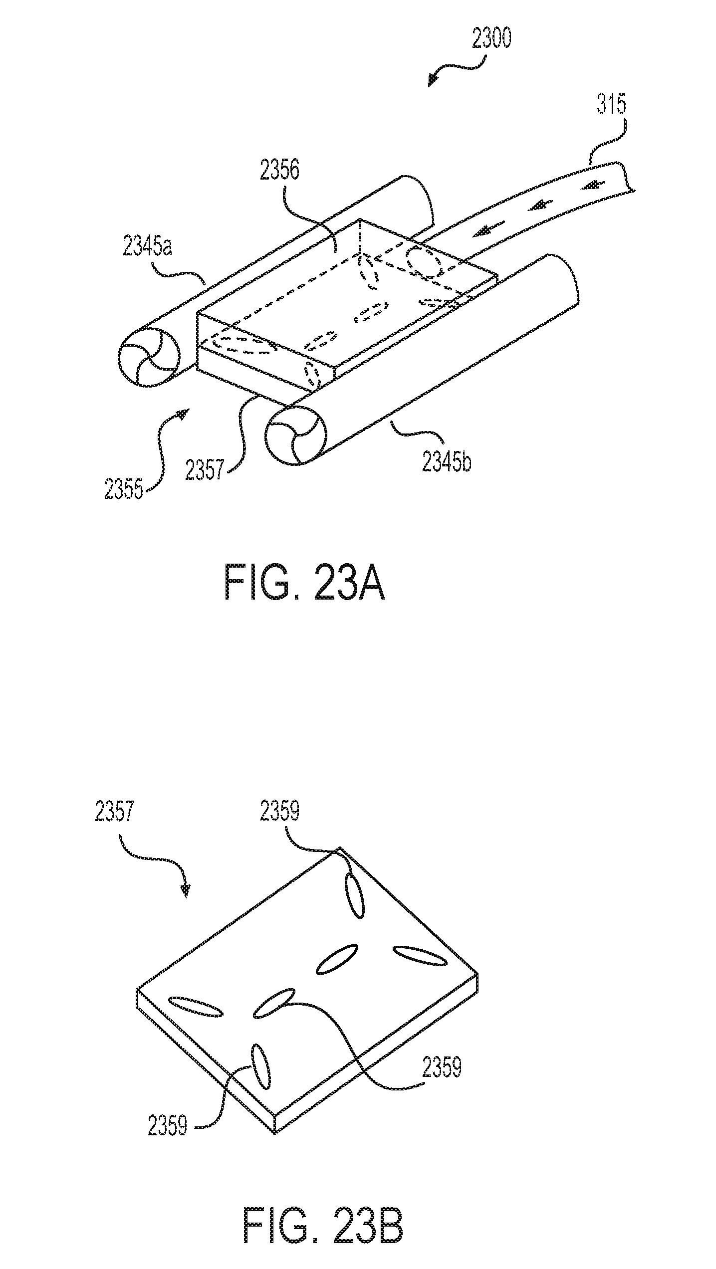
D00017

D00018

D00019

D00020

D00021

D00022

D00023

D00024

D00025

D00026
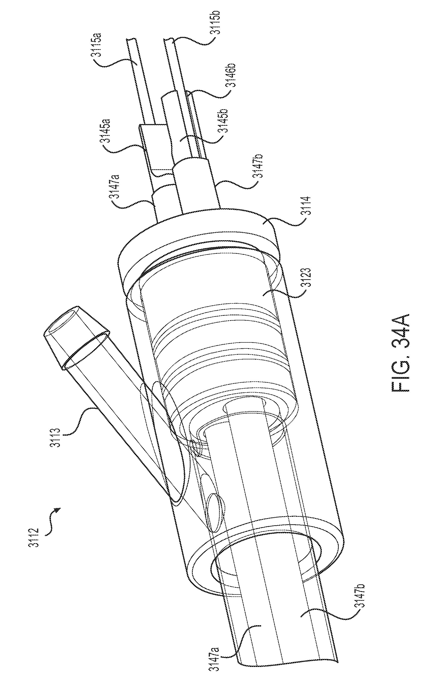
D00027

D00028

XML
uspto.report is an independent third-party trademark research tool that is not affiliated, endorsed, or sponsored by the United States Patent and Trademark Office (USPTO) or any other governmental organization. The information provided by uspto.report is based on publicly available data at the time of writing and is intended for informational purposes only.
While we strive to provide accurate and up-to-date information, we do not guarantee the accuracy, completeness, reliability, or suitability of the information displayed on this site. The use of this site is at your own risk. Any reliance you place on such information is therefore strictly at your own risk.
All official trademark data, including owner information, should be verified by visiting the official USPTO website at www.uspto.gov. This site is not intended to replace professional legal advice and should not be used as a substitute for consulting with a legal professional who is knowledgeable about trademark law.