Method and apparatus for providing a polarization selective holographic waveguide device
Popovich , et al. December 8, 2
U.S. patent number 10,859,768 [Application Number 16/086,578] was granted by the patent office on 2020-12-08 for method and apparatus for providing a polarization selective holographic waveguide device. This patent grant is currently assigned to DigiLens Inc.. The grantee listed for this patent is DigiLens Inc.. Invention is credited to Alastair John Grant, Milan Momcilo Popovich, Jonathan David Waldern.


View All Diagrams
| United States Patent | 10,859,768 |
| Popovich , et al. | December 8, 2020 |
Method and apparatus for providing a polarization selective holographic waveguide device
Abstract
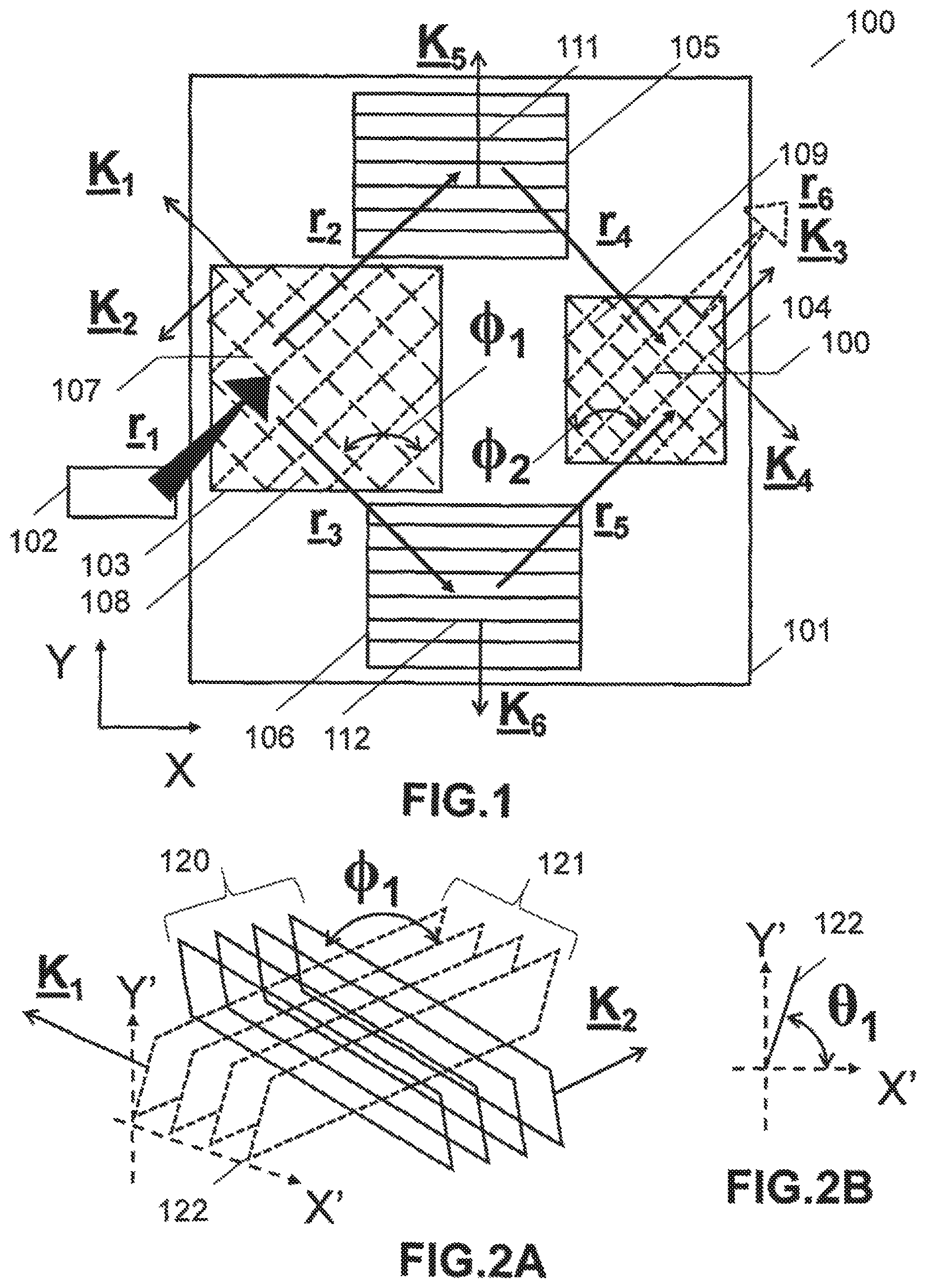
A waveguide apparatus, comprises: disposed in at least one layer: an input coupler; a first fold grating; a second fold grating; an output coupler; and a source of light optically coupled to the waveguide providing at least first and second polarizations of the light and at least one wavelength. The input coupler is configured to cause the first polarization light to travel along a first total internal reflection (TIR) path and the second polarization light to travel along a second TIR path.
| Inventors: | Popovich; Milan Momcilo (Leicester, GB), Waldern; Jonathan David (Los Altos Hills, CA), Grant; Alastair John (San Jose, CA) | ||||||||||
|---|---|---|---|---|---|---|---|---|---|---|---|
| Applicant: |
|
||||||||||
| Assignee: | DigiLens Inc. (Sunnyvale,
CA) |
||||||||||
| Family ID: | 58633026 | ||||||||||
| Appl. No.: | 16/086,578 | ||||||||||
| Filed: | March 23, 2017 | ||||||||||
| PCT Filed: | March 23, 2017 | ||||||||||
| PCT No.: | PCT/GB2017/000040 | ||||||||||
| 371(c)(1),(2),(4) Date: | September 19, 2018 | ||||||||||
| PCT Pub. No.: | WO2017/162999 | ||||||||||
| PCT Pub. Date: | September 28, 2017 |
Prior Publication Data
| Document Identifier | Publication Date | |
|---|---|---|
| US 20190121027 A1 | Apr 25, 2019 | |
Related U.S. Patent Documents
| Application Number | Filing Date | Patent Number | Issue Date | ||
|---|---|---|---|---|---|
| 62391333 | Apr 27, 2016 | ||||
| 62390271 | Mar 24, 2016 | ||||
| Current U.S. Class: | 1/1 |
| Current CPC Class: | G02B 6/2773 (20130101); G02B 27/0081 (20130101); G02B 27/017 (20130101); G02B 27/286 (20130101); G02B 27/283 (20130101); G02B 6/2726 (20130101); G02B 6/34 (20130101) |
| Current International Class: | G02B 6/27 (20060101); G02B 27/01 (20060101); G02B 27/28 (20060101); G02B 27/00 (20060101); G02B 6/34 (20060101) |
References Cited [Referenced By]
U.S. Patent Documents
| 1043938 | November 1912 | Huttenlocher |
| 2141884 | December 1938 | Sonnefeld |
| 3482498 | December 1969 | Becker |
| 3620601 | November 1971 | Leonard et al. |
| 3741716 | June 1973 | Johne et al. |
| 3843231 | October 1974 | Borel et al. |
| 3851303 | November 1974 | Muller |
| 3885095 | May 1975 | Wolfson et al. |
| 3940204 | February 1976 | Withrington |
| 3965029 | June 1976 | Arora |
| 3975711 | August 1976 | McMahon |
| 4035068 | July 1977 | Rawson |
| 4066334 | January 1978 | Fray et al. |
| 4082432 | April 1978 | Kirschner |
| 4099841 | July 1978 | Ellis |
| 4178074 | December 1979 | Heller |
| 4218111 | August 1980 | Withrington et al. |
| 4232943 | November 1980 | Rogers |
| 4248093 | February 1981 | Andersson et al. |
| 4251137 | February 1981 | Knop et al. |
| 4309070 | January 1982 | St. Leger Searle |
| 4322163 | March 1982 | Schiller |
| 4386361 | May 1983 | Simmonds |
| 4389612 | June 1983 | Simmonds et al. |
| 4403189 | September 1983 | Simmonds |
| 4418993 | December 1983 | Lipton |
| 4472037 | September 1984 | Lipton |
| 4523226 | June 1985 | Lipton et al. |
| 4544267 | October 1985 | Schiller |
| 4562463 | December 1985 | Lipton |
| 4566758 | January 1986 | Bos et al. |
| 4583117 | April 1986 | Lipton et al. |
| 4643515 | February 1987 | Upatnieks |
| 4647967 | March 1987 | Kirschner et al. |
| 4688900 | August 1987 | Doane et al. |
| 4711512 | December 1987 | Upatnieks |
| 4714320 | December 1987 | Banbury |
| 4728547 | March 1988 | Vaz et al. |
| 4729640 | March 1988 | Sakata et al. |
| 4743083 | May 1988 | Schimpe |
| 4749256 | June 1988 | Bell et al. |
| 4765703 | August 1988 | Suzuki et al. |
| 4775218 | October 1988 | Wood et al. |
| 4791788 | December 1988 | Simmonds et al. |
| 4792850 | December 1988 | Liptoh et al. |
| 4799765 | January 1989 | Ferrer |
| 4811414 | March 1989 | Fishbine et al. |
| 4848093 | July 1989 | Simmonds et al. |
| 4854688 | August 1989 | Hayford et al. |
| 4860294 | August 1989 | Winzer et al. |
| 4884876 | December 1989 | Lipton et al. |
| 4890902 | January 1990 | Doane et al. |
| 4928301 | May 1990 | Smoot |
| 4933976 | June 1990 | Fishbine et al. |
| 4938568 | July 1990 | Margerum et al. |
| 4946245 | August 1990 | Chamberlin et al. |
| 4960311 | October 1990 | Moss et al. |
| 4964701 | October 1990 | Dorschner et al. |
| 4967268 | October 1990 | Lipton et al. |
| 4970129 | November 1990 | Ingwall et al. |
| 4971719 | November 1990 | Vaz et al. |
| 4994204 | February 1991 | Doane et al. |
| 5004323 | April 1991 | West |
| 5007711 | April 1991 | Wood et al. |
| 5009483 | April 1991 | Rockwell et al. |
| 5033814 | July 1991 | Brown et al. |
| 5035734 | July 1991 | Honkanen et al. |
| 5053834 | October 1991 | Simmonds |
| 5063441 | November 1991 | Lipton et al. |
| 5076664 | December 1991 | Migozzi |
| 5079416 | January 1992 | Filipovich |
| 5096282 | March 1992 | Margerum et al. |
| 5099343 | March 1992 | Margerum et al. |
| 5109465 | April 1992 | Klopotek |
| 5110034 | May 1992 | Simmonds et al. |
| 5117285 | May 1992 | Nelson et al. |
| 5117302 | May 1992 | Lipton |
| 5119454 | June 1992 | McMahon et al. |
| 5124821 | June 1992 | Antier et al. |
| 5139192 | August 1992 | Simmonds et al. |
| 5142357 | August 1992 | Lipton et al. |
| 5142644 | August 1992 | Vansteenkiste et al. |
| 5148302 | September 1992 | Nagano et al. |
| 5151958 | September 1992 | Honkanen |
| 5153751 | October 1992 | Ishikawa et al. |
| 5159445 | October 1992 | Gitlin et al. |
| 5160523 | November 1992 | Honkanen et al. |
| 5181133 | January 1993 | Lipton |
| 5183545 | February 1993 | Branca et al. |
| 5187597 | February 1993 | Kato et al. |
| 5193000 | March 1993 | Lipton et al. |
| 5198912 | March 1993 | Ingwall et al. |
| 5200861 | April 1993 | Moskovich et al. |
| 5210624 | May 1993 | Matsumoto et al. |
| 5218360 | June 1993 | Goetz et al. |
| 5218480 | June 1993 | Moskovich et al. |
| 5224198 | June 1993 | Jachimowicz et al. |
| 5239372 | August 1993 | Lipton |
| 5240636 | August 1993 | Doane et al. |
| 5241337 | August 1993 | Betensky et al. |
| 5242476 | September 1993 | Bartel et al. |
| 5243413 | September 1993 | Gitlin et al. |
| 5251048 | October 1993 | Doane et al. |
| 5264950 | November 1993 | West et al. |
| 5268792 | December 1993 | Kreitzer et al. |
| 5284499 | February 1994 | Harvey et al. |
| 5295208 | March 1994 | Caulfield et al. |
| 5296967 | March 1994 | Moskovich et al. |
| 5299289 | March 1994 | Omae et al. |
| 5303085 | April 1994 | Rallison |
| 5306923 | April 1994 | Kazmierski et al. |
| 5309283 | May 1994 | Kreitzer et al. |
| 5313330 | May 1994 | Betensky |
| 5315324 | May 1994 | Kubelik et al. |
| 5315419 | May 1994 | Saupe et al. |
| 5315440 | May 1994 | Betensky et al. |
| 5317405 | May 1994 | Kuriki et al. |
| 5327269 | July 1994 | Tilton et al. |
| 5329363 | July 1994 | Moskovich et al. |
| 5341230 | August 1994 | Smith |
| 5343147 | August 1994 | Sager et al. |
| 5351151 | September 1994 | Levy |
| 5359362 | October 1994 | Lewis et al. |
| 5363220 | November 1994 | Kuwayama et al. |
| 5368770 | November 1994 | Saupe et al. |
| 5369511 | November 1994 | Amos |
| 5371626 | December 1994 | Betensky |
| 5400069 | March 1995 | Braun et al. |
| 5408346 | April 1995 | Trissel et al. |
| 5410370 | April 1995 | Janssen |
| 5416510 | May 1995 | Lipton et al. |
| 5416514 | May 1995 | Janssen et al. |
| 5418584 | May 1995 | Larson |
| 5418871 | May 1995 | Revelli et al. |
| 5428480 | June 1995 | Betensky et al. |
| 5437811 | August 1995 | Doane et al. |
| 5438357 | August 1995 | McNelley |
| 5452385 | September 1995 | Izumi et al. |
| 5453863 | September 1995 | West et al. |
| 5455693 | October 1995 | Wreede et al. |
| 5455713 | October 1995 | Kreitzer et al. |
| 5463428 | October 1995 | Lipton et al. |
| 5465311 | November 1995 | Caulfield et al. |
| 5471326 | November 1995 | Hall et al. |
| 5473222 | December 1995 | Thoeny et al. |
| 5476611 | December 1995 | Nolan et al. |
| 5481321 | January 1996 | Lipton |
| 5485313 | January 1996 | Betensky |
| 5493430 | February 1996 | Lu et al. |
| 5493448 | February 1996 | Betensky et al. |
| 5496621 | March 1996 | Makita et al. |
| 5499140 | March 1996 | Betensky |
| 5500671 | March 1996 | Andersson et al. |
| 5500769 | March 1996 | Betensky |
| 5510913 | April 1996 | Hashimoto et al. |
| 5515184 | May 1996 | Caulfield et al. |
| 5516455 | May 1996 | Jacobine et al. |
| 5524272 | June 1996 | Podowski et al. |
| 5530566 | June 1996 | Kumar |
| 5532736 | July 1996 | Kuriki et al. |
| 5532875 | July 1996 | Betemsky |
| 5537232 | July 1996 | Biles |
| RE35310 | August 1996 | Moskovich |
| 5543950 | August 1996 | Lavrentovich et al. |
| 5559637 | September 1996 | Moskovich et al. |
| 5572248 | November 1996 | Allen et al. |
| 5572250 | November 1996 | Lipton et al. |
| 5576888 | November 1996 | Betensky |
| 5579026 | November 1996 | Tabata |
| 5583795 | December 1996 | Smyth |
| 5585035 | December 1996 | Nerad et al. |
| 5593615 | January 1997 | Nerad et al. |
| 5604611 | February 1997 | Saburi et al. |
| 5606433 | February 1997 | Yin et al. |
| 5612733 | March 1997 | Flohr |
| 5612734 | March 1997 | Nelson et al. |
| 5619254 | April 1997 | McNelley |
| 5619586 | April 1997 | Sibbald et al. |
| 5621529 | April 1997 | Gordon et al. |
| 5621552 | April 1997 | Coates et al. |
| 5625495 | April 1997 | Moskovich et al. |
| 5629259 | May 1997 | Akada et al. |
| 5631107 | May 1997 | Tarumi et al. |
| 5633100 | May 1997 | Mickish et al. |
| 5646785 | July 1997 | Gilboa et al. |
| 5648857 | July 1997 | Ando et al. |
| 5661577 | August 1997 | Jenkins et al. |
| 5661603 | August 1997 | Hanano et al. |
| 5665494 | September 1997 | Kawabata et al. |
| 5668614 | September 1997 | Chien et al. |
| 5668907 | September 1997 | Veligdan |
| 5677797 | October 1997 | Betensky et al. |
| 5680231 | October 1997 | Grinberg et al. |
| 5680411 | October 1997 | Ramdane et al. |
| 5682255 | October 1997 | Friesem et al. |
| 5686931 | November 1997 | Fuenfschilling et al. |
| 5686975 | November 1997 | Lipton |
| 5691795 | November 1997 | Doane et al. |
| 5694230 | December 1997 | Welch |
| 5695682 | December 1997 | Doane et al. |
| 5701132 | December 1997 | Kollin et al. |
| 5706108 | January 1998 | Ando et al. |
| 5706136 | January 1998 | Okuyama et al. |
| 5707925 | January 1998 | Akada et al. |
| 5710645 | January 1998 | Phillips et al. |
| 5724189 | March 1998 | Ferrante |
| 5724463 | March 1998 | Deacon et al. |
| 5726782 | March 1998 | Kato et al. |
| 5727098 | March 1998 | Jacobson |
| 5729242 | March 1998 | Margerum et al. |
| 5731060 | March 1998 | Hirukawa et al. |
| 5731853 | March 1998 | Taketomi et al. |
| 5742262 | April 1998 | Tabata et al. |
| 5745266 | April 1998 | Smith et al. |
| 5745301 | April 1998 | Betensky et al. |
| 5748272 | May 1998 | Tanaka et al. |
| 5748277 | May 1998 | Huang et al. |
| 5751452 | May 1998 | Tanaka et al. |
| 5757546 | May 1998 | Lipton et al. |
| 5760931 | June 1998 | Saburi et al. |
| 5764414 | June 1998 | King et al. |
| 5790288 | August 1998 | Jager et al. |
| 5790314 | August 1998 | Duck et al. |
| 5798641 | August 1998 | Spagna et al. |
| 5808804 | September 1998 | Moskovich |
| 5812608 | September 1998 | Valimaki et al. |
| 5822089 | October 1998 | Phillips et al. |
| 5822127 | October 1998 | Chen et al. |
| 5825448 | October 1998 | Bos et al. |
| 5831700 | November 1998 | Li et al. |
| 5835661 | November 1998 | Tai et al. |
| 5841507 | November 1998 | Barnes |
| 5841587 | November 1998 | Moskovich et al. |
| 5847787 | December 1998 | Fredley et al. |
| 5856842 | January 1999 | Tedesco |
| 5857043 | January 1999 | Cook et al. |
| 5867238 | February 1999 | Miller et al. |
| 5867618 | February 1999 | Ito et al. |
| 5868951 | February 1999 | Schuck, III et al. |
| 5870228 | February 1999 | Kreitzer et al. |
| 5875012 | February 1999 | Crawford et al. |
| 5877826 | March 1999 | Yang et al. |
| 5886822 | March 1999 | Spitzer |
| 5892598 | April 1999 | Asakawa et al. |
| 5892599 | April 1999 | Bahuguna |
| 5898511 | April 1999 | Mizutani et al. |
| 5900987 | May 1999 | Kreitzer et al. |
| 5900989 | May 1999 | Kreitzer |
| 5903395 | May 1999 | Rallison et al. |
| 5903396 | May 1999 | Rallison |
| 5907416 | May 1999 | Hegg et al. |
| 5907436 | May 1999 | Perry et al. |
| 5917459 | June 1999 | Son et al. |
| 5926147 | July 1999 | Sehm et al. |
| 5929946 | July 1999 | Sharp et al. |
| 5929960 | July 1999 | West et al. |
| 5930433 | July 1999 | Williamson et al. |
| 5936776 | August 1999 | Kreitzer |
| 5937115 | August 1999 | Domash |
| 5942157 | August 1999 | Sutherland et al. |
| 5945893 | August 1999 | Plessky et al. |
| 5949302 | September 1999 | Sarkka |
| 5949508 | September 1999 | Kumar et al. |
| 5956113 | September 1999 | Crawford |
| 5962147 | October 1999 | Shalhub et al. |
| 5963375 | October 1999 | Kreitzer |
| 5966223 | October 1999 | Friesem et al. |
| 5969874 | October 1999 | Moskovich |
| 5969876 | October 1999 | Kreitzer et al. |
| 5973727 | October 1999 | McGrew et al. |
| 5974162 | October 1999 | Metz et al. |
| 5985422 | November 1999 | Krauter |
| 5986746 | November 1999 | Metz et al. |
| 5991087 | November 1999 | Rallison |
| 5999089 | December 1999 | Carlson et al. |
| 5999282 | December 1999 | Suzuki et al. |
| 5999314 | December 1999 | Asakura et al. |
| 6014187 | January 2000 | Taketomi et al. |
| 6023375 | February 2000 | Kreitzer |
| 6042947 | March 2000 | Asakura et al. |
| 6043585 | March 2000 | Plessky et al. |
| 6046585 | April 2000 | Simmonds |
| 6052540 | April 2000 | Koyama |
| 6061107 | May 2000 | Yang |
| 6061463 | May 2000 | Metz et al. |
| 6069728 | May 2000 | Huignard et al. |
| 6075626 | June 2000 | Mizutani et al. |
| 6078427 | June 2000 | Fontaine et al. |
| 6094311 | July 2000 | Moskovich |
| 6097551 | August 2000 | Kreitzer |
| 6104448 | August 2000 | Doane et al. |
| 6107943 | August 2000 | Schroeder |
| 6115152 | September 2000 | Popovich et al. |
| 6118908 | September 2000 | Bischel et al. |
| 6121899 | September 2000 | Theriault |
| 6127066 | October 2000 | Ueda et al. |
| 6128058 | October 2000 | Walton et al. |
| 6133971 | October 2000 | Silverstein et al. |
| 6133975 | October 2000 | Li et al. |
| 6137630 | October 2000 | Tsou et al. |
| 6141074 | October 2000 | Bos et al. |
| 6141154 | October 2000 | Kreitzer et al. |
| 6151142 | November 2000 | Phillips et al. |
| 6154190 | November 2000 | Yang et al. |
| 6156243 | December 2000 | Kosuga et al. |
| 6167169 | December 2000 | Brinkman et al. |
| 6169594 | January 2001 | Aye et al. |
| 6169613 | January 2001 | Amitai et al. |
| 6169636 | January 2001 | Kreitzer et al. |
| 6176837 | January 2001 | Foxlin |
| 6185016 | February 2001 | Popovich |
| 6188462 | February 2001 | Lavrentovich et al. |
| 6191887 | February 2001 | Michaloski et al. |
| 6195206 | February 2001 | Yona et al. |
| 6195209 | February 2001 | Kreitzer et al. |
| 6204835 | March 2001 | Yang et al. |
| 6211976 | April 2001 | Popovich et al. |
| 6222297 | April 2001 | Perdue |
| 6222675 | April 2001 | Mall et al. |
| 6222971 | April 2001 | Veligdan et al. |
| 6249386 | June 2001 | Yona et al. |
| 6259423 | July 2001 | Tokito et al. |
| 6259559 | July 2001 | Kobayashi et al. |
| 6268839 | July 2001 | Yang et al. |
| 6269203 | July 2001 | Davies et al. |
| 6275031 | August 2001 | Simmonds et al. |
| 6278429 | August 2001 | Ruth et al. |
| 6285813 | September 2001 | Schultz et al. |
| 6297860 | October 2001 | Moskovich et al. |
| 6301056 | October 2001 | Kreitzer et al. |
| 6301057 | October 2001 | Kreitzer et al. |
| 6317083 | November 2001 | Johnson et al. |
| 6317227 | November 2001 | Mizutani et al. |
| 6317228 | November 2001 | Popovich et al. |
| 6317528 | November 2001 | Gadkaree et al. |
| 6320563 | November 2001 | Yang et al. |
| 6321069 | November 2001 | Piirainen |
| 6323989 | November 2001 | Jacobson et al. |
| 6324014 | November 2001 | Moskovich et al. |
| 6327089 | December 2001 | Hosaki et al. |
| 6330109 | December 2001 | Ishii et al. |
| 6333819 | December 2001 | Svedenkrans |
| 6340540 | January 2002 | Ueda et al. |
| 6351333 | February 2002 | Araki et al. |
| 6356172 | March 2002 | Koivisto et al. |
| 6356674 | March 2002 | Davis et al. |
| 6359730 | March 2002 | Tervonen |
| 6359737 | March 2002 | Stringfellow |
| 6366281 | April 2002 | Lipton et al. |
| 6366378 | April 2002 | Tervonen et al. |
| 6377238 | April 2002 | McPheters |
| 6377321 | April 2002 | Khan et al. |
| 6388797 | May 2002 | Lipton et al. |
| 6392812 | May 2002 | Howard |
| 6407724 | June 2002 | Waldern et al. |
| 6409687 | June 2002 | Foxlin |
| 6411444 | June 2002 | Moskovich et al. |
| 6414760 | July 2002 | Lopez et al. |
| 6417971 | July 2002 | Moskovich et al. |
| 6437563 | August 2002 | Simmonds et al. |
| 6445512 | September 2002 | Moskovich et al. |
| 6470132 | October 2002 | Nousiainen et al. |
| 6473209 | October 2002 | Popovich |
| 6476974 | November 2002 | Kreitzer et al. |
| 6483303 | November 2002 | Simmonds et al. |
| 6486997 | November 2002 | Bruzzone et al. |
| 6504518 | January 2003 | Kuwayama et al. |
| 6504629 | January 2003 | Popovich et al. |
| 6509937 | January 2003 | Moskovich et al. |
| 6518747 | February 2003 | Sager et al. |
| 6519088 | February 2003 | Lipton |
| 6522794 | February 2003 | Bischel et al. |
| 6522795 | February 2003 | Jordan et al. |
| 6524771 | February 2003 | Maeda et al. |
| 6529336 | March 2003 | Kreitzer et al. |
| 6534977 | March 2003 | Duncan et al. |
| 6545778 | April 2003 | Ono et al. |
| 6550949 | April 2003 | Bauer et al. |
| 6552789 | April 2003 | Modro |
| 6557413 | May 2003 | Nieminen et al. |
| 6559813 | May 2003 | DeLuca et al. |
| 6563648 | May 2003 | Gleckman et al. |
| 6563650 | May 2003 | Moskovich et al. |
| 6567014 | May 2003 | Hansen et al. |
| 6567573 | May 2003 | Domash et al. |
| 6577411 | June 2003 | David et al. |
| 6577429 | June 2003 | Kurtz et al. |
| 6580529 | June 2003 | Amitai et al. |
| 6583838 | June 2003 | Hoke et al. |
| 6583873 | June 2003 | Goncharov et al. |
| 6587619 | July 2003 | Kinoshita |
| 6594090 | July 2003 | Kruschwitz et al. |
| 6597176 | July 2003 | Simmonds et al. |
| 6597475 | July 2003 | Shirakura et al. |
| 6598987 | July 2003 | Parikka |
| 6600590 | July 2003 | Roddy et al. |
| 6608720 | August 2003 | Freeman |
| 6611253 | August 2003 | Cohen |
| 6618104 | September 2003 | Date et al. |
| 6625381 | September 2003 | Roddy et al. |
| 6646772 | November 2003 | Popovich et al. |
| 6646810 | November 2003 | Harter, Jr. et al. |
| 6661578 | December 2003 | Hedrick |
| 6667134 | December 2003 | Sutherland et al. |
| 6674578 | January 2004 | Sugiyama et al. |
| 6677086 | January 2004 | Sutehrland et al. |
| 6686815 | February 2004 | Mirshekarl-Syahkal et al. |
| 6690516 | February 2004 | Aritake et al. |
| 6692666 | February 2004 | Sutherland et al. |
| 6699407 | March 2004 | Sutehrland et al. |
| 6706086 | March 2004 | Emig et al. |
| 6706451 | March 2004 | Sutherland et al. |
| 6721096 | April 2004 | Bruzzone et al. |
| 6730442 | May 2004 | Sutherland et al. |
| 6731434 | May 2004 | Hua et al. |
| 6738105 | May 2004 | Hannah et al. |
| 6741189 | May 2004 | Gibbons, II et al. |
| 6744478 | June 2004 | Asakura et al. |
| 6747781 | June 2004 | Trisnadi et al. |
| 6748342 | June 2004 | Dickhaus |
| 6750941 | June 2004 | Satoh et al. |
| 6750995 | June 2004 | Dickson |
| 6757105 | June 2004 | Niv et al. |
| 6771403 | August 2004 | Endo et al. |
| 6776339 | August 2004 | Piikivi |
| 6781701 | August 2004 | Sweetser et al. |
| 6791629 | September 2004 | Moskovich et al. |
| 6791739 | September 2004 | Ramanujan et al. |
| 6804066 | October 2004 | Ha et al. |
| 6805490 | October 2004 | Levola |
| 6821457 | November 2004 | Natarajan et al. |
| 6822713 | November 2004 | Yaroshchuk et al. |
| 6825987 | November 2004 | Repetto et al. |
| 6829095 | December 2004 | Amitai |
| 6830789 | December 2004 | Doane et al. |
| 6833955 | December 2004 | Niv |
| 6836369 | December 2004 | Fujikawa et al. |
| 6844212 | January 2005 | Bond et al. |
| 6844980 | January 2005 | He et al. |
| 6847274 | January 2005 | Salmela et al. |
| 6847488 | January 2005 | Travis |
| 6850210 | February 2005 | Lipton et al. |
| 6853491 | February 2005 | Ruhle et al. |
| 6853493 | February 2005 | Kreitzer et al. |
| 6864861 | March 2005 | Schehrer et al. |
| 6864927 | March 2005 | Cathey |
| 6867888 | March 2005 | Sutherland et al. |
| 6873443 | March 2005 | Joubert et al. |
| 6878494 | April 2005 | Sutehrland et al. |
| 6885483 | April 2005 | Takada |
| 6903872 | June 2005 | Schrader |
| 6909345 | June 2005 | Salmela et al. |
| 6917375 | July 2005 | Akada et al. |
| 6919003 | July 2005 | Ikeda et al. |
| 6922267 | July 2005 | Endo et al. |
| 6926429 | August 2005 | Barlow et al. |
| 6927570 | August 2005 | Simmonds et al. |
| 6927694 | August 2005 | Smith et al. |
| 6940361 | September 2005 | Jokio et al. |
| 6943788 | September 2005 | Tomono |
| 6950173 | September 2005 | Sutherland et al. |
| 6950227 | September 2005 | Schrader |
| 6951393 | October 2005 | Koide |
| 6952312 | October 2005 | Weber et al. |
| 6952435 | October 2005 | Lai et al. |
| 6958662 | October 2005 | Salmela et al. |
| 6958868 | October 2005 | Pender |
| 6963454 | November 2005 | Martins et al. |
| 6972788 | December 2005 | Robertson et al. |
| 6975345 | December 2005 | Lipton et al. |
| 6980365 | December 2005 | Moskovich |
| 6985296 | January 2006 | Lipton et al. |
| 6987908 | January 2006 | Bond et al. |
| 6999239 | February 2006 | Martins et al. |
| 7002618 | February 2006 | Lipton et al. |
| 7002753 | February 2006 | Moskovich et al. |
| 7003075 | February 2006 | Miyake et al. |
| 7003187 | February 2006 | Frick et al. |
| 7006732 | February 2006 | Gunn, III |
| 7009773 | March 2006 | Chaoulov et al. |
| 7018563 | March 2006 | Sutherland et al. |
| 7018686 | March 2006 | Sutehrland et al. |
| 7018744 | March 2006 | Otaki et al. |
| 7019793 | March 2006 | Moskovich et al. |
| 7021777 | April 2006 | Amitai |
| 7026892 | April 2006 | Kajiya |
| 7027671 | April 2006 | Huck et al. |
| 7034748 | April 2006 | Kajiya |
| 7046439 | May 2006 | Kaminsky et al. |
| 7053735 | May 2006 | Salmela et al. |
| 7053991 | May 2006 | Sandusky |
| 7054045 | May 2006 | McPheters et al. |
| 7058434 | June 2006 | Wang et al. |
| 7068405 | June 2006 | Sutherland et al. |
| 7068898 | June 2006 | Buretea et al. |
| 7072020 | July 2006 | Sutherland et al. |
| 7075273 | July 2006 | O'Gorman et al. |
| 7077984 | July 2006 | Natarajan et al. |
| 7081215 | July 2006 | Natarajan et al. |
| 7088457 | August 2006 | Zou et al. |
| 7088515 | August 2006 | Lipton |
| 7095562 | August 2006 | Peng et al. |
| 7099080 | August 2006 | Lipton et al. |
| 7101048 | September 2006 | Travis |
| 7108383 | September 2006 | Mitchell et al. |
| 7110184 | September 2006 | Yona et al. |
| 7119965 | October 2006 | Rolland et al. |
| 7123418 | October 2006 | Weber et al. |
| 7123421 | October 2006 | Moskovich et al. |
| 7126418 | October 2006 | Hunton et al. |
| 7126583 | October 2006 | Breed |
| 7132200 | November 2006 | Ueda et al. |
| 7133084 | November 2006 | Moskovich et al. |
| 7139109 | November 2006 | Mukawa |
| RE39424 | December 2006 | Moskovich |
| 7145729 | December 2006 | Kreitzer et al. |
| 7149385 | December 2006 | Parikka et al. |
| 7151246 | December 2006 | Fein et al. |
| 7158095 | January 2007 | Jenson et al. |
| 7167286 | January 2007 | Anderson et al. |
| 7175780 | February 2007 | Sutherland et al. |
| 7181105 | February 2007 | Teramura et al. |
| 7181108 | February 2007 | Levola |
| 7184002 | February 2007 | Lipton et al. |
| 7184615 | February 2007 | Levola |
| 7186567 | March 2007 | Sutherland et al. |
| 7190849 | March 2007 | Katase |
| 7198737 | April 2007 | Natarajan et al. |
| 7199934 | April 2007 | Yamasaki |
| 7205960 | April 2007 | David |
| 7205964 | April 2007 | Yokoyama et al. |
| 7206107 | April 2007 | Levola |
| 7212175 | May 2007 | Magee et al. |
| 7230767 | June 2007 | Walck et al. |
| 7230770 | June 2007 | Kreitzer et al. |
| 7242527 | July 2007 | Spitzer et al. |
| 7248128 | July 2007 | Mattila et al. |
| 7256915 | August 2007 | Sutherland et al. |
| 7259906 | August 2007 | Islam |
| 7265882 | September 2007 | Sutherland et al. |
| 7265903 | September 2007 | Sutherland et al. |
| 7268946 | September 2007 | Wang |
| 7285903 | October 2007 | Cull et al. |
| 7286272 | October 2007 | Mukawa |
| 7289069 | October 2007 | Ranta |
| RE39911 | November 2007 | Moskovich |
| 7299983 | November 2007 | Piikivi |
| 7301601 | November 2007 | Lin et al. |
| 7312906 | December 2007 | Sutherland et al. |
| 7313291 | December 2007 | Okhotnikov et al. |
| 7319573 | January 2008 | Nishiyama |
| 7320534 | January 2008 | Sugikawa et al. |
| 7323275 | January 2008 | Otaki et al. |
| 7333685 | February 2008 | Stone et al. |
| 7336271 | February 2008 | Ozeki et al. |
| 7339737 | March 2008 | Urey et al. |
| 7339742 | March 2008 | Amitai et al. |
| 7369911 | May 2008 | Volant et al. |
| 7375870 | May 2008 | Schorpp |
| 7375886 | May 2008 | Lipton et al. |
| 7376307 | May 2008 | Singh et al. |
| 7391573 | June 2008 | Amitai |
| 7394865 | July 2008 | Borran et al. |
| 7395181 | July 2008 | Foxlin |
| 7397606 | July 2008 | Peng et al. |
| 7401920 | July 2008 | Kranz et al. |
| 7404644 | July 2008 | Evans et al. |
| 7410286 | August 2008 | Travis |
| 7411637 | August 2008 | Weiss |
| 7413678 | August 2008 | Natarajan et al. |
| 7413679 | August 2008 | Sutherland et al. |
| 7415173 | August 2008 | Kassamakov et al. |
| 7416818 | August 2008 | Sutherland et al. |
| 7418170 | August 2008 | Mukawa et al. |
| 7420733 | September 2008 | Natarajan et al. |
| 7433116 | October 2008 | Islam |
| 7436568 | October 2008 | Kuykendall |
| 7447967 | November 2008 | Onggosanusi et al. |
| 7453612 | November 2008 | Mukawa |
| 7454103 | November 2008 | Parriaux |
| 7457040 | November 2008 | Amitai |
| 7466994 | December 2008 | Pihlaja et al. |
| 7477206 | January 2009 | Cowan et al. |
| 7479354 | January 2009 | Ueda et al. |
| 7480215 | January 2009 | Makela et al. |
| 7482996 | January 2009 | Larson et al. |
| 7483604 | January 2009 | Levola |
| 7492512 | February 2009 | Niv et al. |
| 7496293 | February 2009 | Shamir et al. |
| 7499217 | March 2009 | Cakmakci et al. |
| 7500104 | March 2009 | Goland |
| 7511891 | March 2009 | Messerschmidt et al. |
| 7513668 | April 2009 | Peng et al. |
| 7522344 | April 2009 | Curatu et al. |
| 7525448 | April 2009 | Wilson et al. |
| 7528385 | May 2009 | Volodin et al. |
| 7545429 | June 2009 | Travis |
| 7550234 | June 2009 | Otaki et al. |
| 7567372 | July 2009 | Schorpp |
| 7570322 | August 2009 | Sutherland et al. |
| 7570405 | August 2009 | Sutherland et al. |
| 7570429 | August 2009 | Maliah et al. |
| 7572555 | August 2009 | Takizawa et al. |
| 7573640 | August 2009 | Nivon et al. |
| 7576916 | August 2009 | Amitai |
| 7577326 | August 2009 | Amitai |
| 7579119 | August 2009 | Ueda et al. |
| 7583423 | September 2009 | Sutherland et al. |
| 7587110 | September 2009 | Singh et al. |
| 7588863 | September 2009 | Takizawa et al. |
| 7589900 | September 2009 | Powell |
| 7589901 | September 2009 | DeJong et al. |
| 7592988 | September 2009 | Katase |
| 7593575 | September 2009 | Houle et al. |
| 7597447 | October 2009 | Larson et al. |
| 7599012 | October 2009 | Nakamura et al. |
| 7600893 | October 2009 | Laino et al. |
| 7602552 | October 2009 | Blumenfeld |
| 7605719 | October 2009 | Wenger et al. |
| 7605774 | October 2009 | Brandt et al. |
| 7605882 | October 2009 | Sutherland et al. |
| 7616270 | November 2009 | Hirabayashi et al. |
| 7617022 | November 2009 | Wood et al. |
| 7618750 | November 2009 | Ueda et al. |
| 7619739 | November 2009 | Sutherland et al. |
| 7619825 | November 2009 | Peng et al. |
| 7629086 | December 2009 | Otaki et al. |
| 7639208 | December 2009 | Ha et al. |
| 7639911 | December 2009 | Lee et al. |
| 7643214 | January 2010 | Amitai |
| 7656585 | February 2010 | Powell et al. |
| 7660047 | February 2010 | Travis et al. |
| 7672055 | March 2010 | Amitai |
| 7672549 | March 2010 | Ghosh et al. |
| 7691248 | April 2010 | Ikeda et al. |
| 7710622 | May 2010 | Takabayashi et al. |
| 7710654 | May 2010 | Ashkenazi et al. |
| 7724441 | May 2010 | Amitai |
| 7724442 | May 2010 | Amitai |
| 7724443 | May 2010 | Amitai |
| 7733571 | June 2010 | Li |
| 7733572 | June 2010 | Brown et al. |
| 7740387 | June 2010 | Schultz et al. |
| 7747113 | June 2010 | Mukawa et al. |
| 7751122 | July 2010 | Amitai |
| 7751662 | July 2010 | Kleemann et al. |
| 7764413 | July 2010 | Levola |
| 7777819 | August 2010 | Simmonds |
| 7778305 | August 2010 | Parriaux et al. |
| 7778508 | August 2010 | Hirayama |
| 7843642 | November 2010 | Shaoulov et al. |
| 7847235 | December 2010 | Krupkin et al. |
| 7864427 | January 2011 | Korenaga et al. |
| 7865080 | January 2011 | Hecker et al. |
| 7866869 | January 2011 | Karakawa |
| 7872707 | January 2011 | Sutherland et al. |
| 7872804 | January 2011 | Moon et al. |
| 7884593 | February 2011 | Simmonds et al. |
| 7884985 | February 2011 | Amitai et al. |
| 7887186 | February 2011 | Watanabe |
| 7903921 | March 2011 | Ostergard |
| 7907342 | March 2011 | Simmonds et al. |
| 7920787 | April 2011 | Gentner et al. |
| 7928862 | April 2011 | Matthews |
| 7936519 | May 2011 | Mukawa et al. |
| 7944428 | May 2011 | Travis |
| 7944616 | May 2011 | Mukawa |
| 7949214 | May 2011 | DeJong et al. |
| 7961117 | June 2011 | Zimmerman et al. |
| 7969644 | June 2011 | Tilleman et al. |
| 7969657 | June 2011 | Cakmakci et al. |
| 7970246 | June 2011 | Travis et al. |
| 7976208 | July 2011 | Travis |
| 7984884 | July 2011 | Iliev et al. |
| 7999982 | August 2011 | Endo et al. |
| 8000020 | August 2011 | Amitai et al. |
| 8000491 | August 2011 | Brodkin et al. |
| 8004765 | August 2011 | Amitai |
| 8014050 | September 2011 | McGrew |
| 8016475 | September 2011 | Travis |
| 8018579 | September 2011 | Krah |
| 8022942 | September 2011 | Bathiche et al. |
| 8023783 | September 2011 | Mukawa et al. |
| RE42992 | December 2011 | David |
| 8073296 | December 2011 | Mukawa et al. |
| 8077274 | December 2011 | Sutherland et al. |
| 8079713 | December 2011 | Ashkenazi |
| 8082222 | December 2011 | Rangarajan et al. |
| 8086030 | December 2011 | Gordon et al. |
| 8089568 | January 2012 | Brown et al. |
| 8093451 | January 2012 | Spangenberg et al. |
| 8098439 | January 2012 | Amitai et al. |
| 8107023 | January 2012 | Simmonds et al. |
| 8107780 | January 2012 | Simmonds |
| 8120548 | February 2012 | Barber |
| 8132948 | March 2012 | Owen et al. |
| 8132976 | March 2012 | Odell et al. |
| 8134434 | March 2012 | Diederichs et al. |
| 8136690 | March 2012 | Fang et al. |
| 8137981 | March 2012 | Andrew et al. |
| 8142016 | March 2012 | Legerton et al. |
| 8149086 | April 2012 | Klein et al. |
| 8152315 | April 2012 | Travis et al. |
| 8155489 | April 2012 | Saarikko et al. |
| 8159752 | April 2012 | Wertheim et al. |
| 8160409 | April 2012 | Large |
| 8160411 | April 2012 | Levola |
| 8167173 | May 2012 | Simmonds et al. |
| 8186874 | May 2012 | Sinbar et al. |
| 8188925 | May 2012 | DeJean |
| 8189263 | May 2012 | Wang et al. |
| 8189973 | May 2012 | Travis et al. |
| 8194325 | June 2012 | Levola et al. |
| 8199803 | June 2012 | Hauske et al. |
| 8213065 | July 2012 | Mukawa |
| 8213755 | July 2012 | Mukawa et al. |
| 8220966 | July 2012 | Mukawa |
| 8224133 | July 2012 | Popovich et al. |
| 8233204 | July 2012 | Robbins et al. |
| 8253914 | August 2012 | Kajiya et al. |
| 8254031 | August 2012 | Levola |
| 8264498 | September 2012 | Vanderkamp et al. |
| 8294749 | October 2012 | Cable |
| 8295710 | October 2012 | Marcus |
| 8301031 | October 2012 | Gentner et al. |
| 8305577 | November 2012 | Kivioja et al. |
| 8306423 | November 2012 | Gottwald et al. |
| 8310327 | November 2012 | Willers et al. |
| 8314819 | November 2012 | Kimmel et al. |
| 8314993 | November 2012 | Levola et al. |
| 8320032 | November 2012 | Levola |
| 8321810 | November 2012 | Heintze |
| 8325166 | December 2012 | Akutsu et al. |
| 8329773 | December 2012 | Facke et al. |
| 8335040 | December 2012 | Mukawa et al. |
| 8351744 | January 2013 | Travis et al. |
| 8354640 | January 2013 | Hamre et al. |
| 8354806 | January 2013 | Travis et al. |
| 8355610 | January 2013 | Simmonds |
| 8369019 | February 2013 | Baker et al. |
| 8376548 | February 2013 | Schultz |
| 8382293 | February 2013 | Phillips, III et al. |
| 8384504 | February 2013 | Diederichs et al. |
| 8384694 | February 2013 | Powell et al. |
| 8384730 | February 2013 | Vanderkamp et al. |
| 8396339 | March 2013 | Mukawa et al. |
| 8398242 | March 2013 | Yamamoto et al. |
| 8403490 | March 2013 | Sugiyama et al. |
| 8422840 | April 2013 | Large |
| 8427439 | April 2013 | Larsen et al. |
| 8432363 | April 2013 | Saarikko et al. |
| 8432372 | April 2013 | Butler et al. |
| 8432614 | April 2013 | Amitai |
| 8441731 | May 2013 | Sprague |
| 8447365 | May 2013 | Imanuel |
| 8466953 | June 2013 | Levola et al. |
| 8472119 | June 2013 | Kelly |
| 8472120 | June 2013 | Border et al. |
| 8477261 | July 2013 | Travis et al. |
| 8481130 | July 2013 | Harding et al. |
| 8482858 | July 2013 | Sprague |
| 8488246 | July 2013 | Border et al. |
| 8491121 | July 2013 | Tilleman et al. |
| 8491136 | July 2013 | Travis et al. |
| 8493366 | July 2013 | Bathiche et al. |
| 8493662 | July 2013 | Noui |
| 8494229 | July 2013 | Jarvenpaa |
| 8508848 | August 2013 | Saarikko |
| 8520309 | August 2013 | Sprague |
| 8547638 | October 2013 | Levola |
| 8548290 | October 2013 | Travers et al. |
| 8565560 | October 2013 | Popovich et al. |
| 8578038 | November 2013 | Kaikuranta et al. |
| 8581831 | November 2013 | Travis |
| 8582206 | November 2013 | Travis |
| 8593734 | November 2013 | Laakkonen |
| 8611014 | December 2013 | Valera et al. |
| 8619062 | December 2013 | Powell et al. |
| 8633786 | January 2014 | Ermolov et al. |
| 8634120 | January 2014 | Popovich et al. |
| 8634139 | January 2014 | Brown et al. |
| 8639072 | January 2014 | Popovich et al. |
| 8643691 | February 2014 | Rosenfeld et al. |
| 8643948 | February 2014 | Amitai et al. |
| 8649099 | February 2014 | Schultz et al. |
| 8654420 | February 2014 | Simmonds |
| 8659826 | February 2014 | Brown et al. |
| D701206 | March 2014 | Luckey et al. |
| 8670029 | March 2014 | McEldowney |
| 8693087 | April 2014 | Nowatzyk et al. |
| 8698705 | April 2014 | Burke et al. |
| 8731350 | May 2014 | Lin et al. |
| 8736802 | May 2014 | Kajiya et al. |
| 8736963 | May 2014 | Robbins et al. |
| 8742952 | June 2014 | Bold |
| 8746008 | June 2014 | Mauritsen et al. |
| 8749886 | June 2014 | Gupta |
| 8749890 | June 2014 | Wood et al. |
| 8767294 | July 2014 | Chen et al. |
| 8786923 | July 2014 | Chuang et al. |
| 8810600 | August 2014 | Bohn et al. |
| 8810913 | August 2014 | Simmonds et al. |
| 8810914 | August 2014 | Amitai |
| 8814691 | August 2014 | Haddick et al. |
| 8816578 | August 2014 | Peng et al. |
| 8817350 | August 2014 | Robbins et al. |
| 8824836 | September 2014 | Sugiyama et al. |
| 8830143 | September 2014 | Pitchford et al. |
| 8830584 | September 2014 | Saarikko et al. |
| 8830588 | September 2014 | Brown et al. |
| 8842368 | September 2014 | Simmonds et al. |
| 8859412 | October 2014 | Jain |
| 8872435 | October 2014 | Kreitzer et al. |
| 8873149 | October 2014 | Bohn et al. |
| 8873150 | October 2014 | Amitai |
| 8885112 | November 2014 | Popovich et al. |
| 8885997 | November 2014 | Nguyen et al. |
| 8903207 | December 2014 | Brown et al. |
| 8906088 | December 2014 | Pugh et al. |
| 8913324 | December 2014 | Schrader |
| 8913865 | December 2014 | Bennett |
| 8917453 | December 2014 | Bohn et al. |
| 8933144 | January 2015 | Enomoto et al. |
| 8937771 | January 2015 | Robbins et al. |
| 8937772 | January 2015 | Burns et al. |
| 8938141 | January 2015 | Magnusson |
| 8950867 | February 2015 | Macnamara |
| 8964298 | February 2015 | Haddick et al. |
| 8965152 | February 2015 | Simmonds |
| 8985803 | March 2015 | Bohn et al. |
| 8989535 | March 2015 | Robbins |
| 9019595 | April 2015 | Jain |
| 9025253 | May 2015 | Hadad et al. |
| 9035344 | May 2015 | Jain |
| 9075184 | July 2015 | Popovich et al. |
| 9081178 | July 2015 | Simmonds et al. |
| 9097890 | August 2015 | Miller et al. |
| 9128226 | September 2015 | Fattal et al. |
| 9129295 | September 2015 | Border et al. |
| 9164290 | October 2015 | Robbins et al. |
| 9176324 | November 2015 | Scherer et al. |
| 9201270 | December 2015 | Fattal et al. |
| 9215293 | December 2015 | Miller |
| 9244275 | January 2016 | Li |
| 9244280 | January 2016 | Tiana et al. |
| 9244281 | January 2016 | Zimmerman et al. |
| 9269854 | February 2016 | Jain |
| 9274338 | March 2016 | Robbins et al. |
| 9274339 | March 2016 | Brown et al. |
| 9310566 | April 2016 | Valera et al. |
| 9329325 | May 2016 | Simmonds et al. |
| 9335604 | May 2016 | Popovich et al. |
| 9341846 | May 2016 | Popovich et al. |
| 9354366 | May 2016 | Jain |
| 9366862 | June 2016 | Haddick et al. |
| 9366864 | June 2016 | Brown et al. |
| 9372347 | June 2016 | Levola et al. |
| 9377623 | June 2016 | Robbins et al. |
| 9377852 | June 2016 | Shapiro et al. |
| 9389415 | July 2016 | Fattal et al. |
| 9400395 | July 2016 | Travers et al. |
| 9423360 | August 2016 | Kostamo et al. |
| 9429692 | August 2016 | Saarikko et al. |
| 9431794 | August 2016 | Jain |
| 9456744 | October 2016 | Popovich et al. |
| 9459451 | October 2016 | Saarikko et al. |
| 9464779 | October 2016 | Popovich et al. |
| 9465213 | October 2016 | Simmonds |
| 9465227 | October 2016 | Popovich et al. |
| 9494799 | November 2016 | Robbins et al. |
| 9507150 | November 2016 | Stratton et al. |
| 9513480 | December 2016 | Saarikko et al. |
| 9519089 | December 2016 | Brown et al. |
| 9523852 | December 2016 | Brown et al. |
| 9535253 | January 2017 | Levola et al. |
| 9541383 | January 2017 | Abovitz et al. |
| 9541763 | January 2017 | Heberlein et al. |
| 9547174 | January 2017 | Gao et al. |
| 9551874 | January 2017 | Amitai et al. |
| 9551880 | January 2017 | Amitai et al. |
| 9599813 | March 2017 | Stratton et al. |
| 9612403 | April 2017 | Abovitz et al. |
| 9632226 | April 2017 | Waldern et al. |
| 9635352 | April 2017 | Henry et al. |
| 9648313 | May 2017 | Henry et al. |
| 9651368 | May 2017 | Abovitz et al. |
| 9664824 | May 2017 | Simmonds et al. |
| 9664910 | May 2017 | Mansharof et al. |
| 9674413 | June 2017 | Tiana et al. |
| 9678345 | June 2017 | Melzer et al. |
| 9679367 | June 2017 | Wald |
| 9715067 | July 2017 | Brown et al. |
| 9715110 | July 2017 | Brown et al. |
| 9726540 | August 2017 | Popovich et al. |
| 9727772 | August 2017 | Popovich et al. |
| 9733475 | August 2017 | Brown et al. |
| 9746688 | August 2017 | Popovich et al. |
| 9754507 | September 2017 | Wenger et al. |
| 9762895 | September 2017 | Henry et al. |
| 9766465 | September 2017 | Tiana et al. |
| 9785231 | October 2017 | Zimmerman |
| 9791694 | October 2017 | Haverkamp et al. |
| 9804389 | October 2017 | Popovich et al. |
| 9823423 | November 2017 | Waldern et al. |
| 9874931 | January 2018 | Koenck et al. |
| 9933684 | April 2018 | Brown et al. |
| 9977247 | May 2018 | Brown et al. |
| 10089516 | October 2018 | Popovich et al. |
| 10156681 | December 2018 | Waldern et al. |
| 10216061 | February 2019 | Popovich et al. |
| 10234696 | March 2019 | Popovich et al. |
| 10241330 | March 2019 | Popovich et al. |
| 10423813 | September 2019 | Popovich et al. |
| 10527797 | January 2020 | Waldern et al. |
| 10545346 | January 2020 | Waldern et al. |
| 10678053 | June 2020 | Waldern et al. |
| 10690916 | June 2020 | Popovich et al. |
| 2001/0024177 | September 2001 | Popovich |
| 2001/0043163 | November 2001 | Waldern et al. |
| 2001/0050756 | December 2001 | Lipton et al. |
| 2002/0003509 | January 2002 | Lipton et al. |
| 2002/0009299 | January 2002 | Lipton |
| 2002/0011969 | January 2002 | Lipton et al. |
| 2002/0012064 | January 2002 | Yamaguchi |
| 2002/0021461 | February 2002 | Ono et al. |
| 2002/0036825 | March 2002 | Lipton et al. |
| 2002/0047837 | April 2002 | Suyama et al. |
| 2002/0075240 | June 2002 | Lieberman et al. |
| 2002/0110077 | August 2002 | Drobot et al. |
| 2002/0126332 | September 2002 | Popovich |
| 2002/0127497 | September 2002 | Brown et al. |
| 2002/0131175 | September 2002 | Yagi et al. |
| 2002/0196332 | December 2002 | Lipton et al. |
| 2003/0007070 | January 2003 | Lipton et al. |
| 2003/0038912 | February 2003 | Broer et al. |
| 2003/0039442 | February 2003 | Bond et al. |
| 2003/0063042 | April 2003 | Friesem et al. |
| 2003/0063884 | April 2003 | Smith et al. |
| 2003/0067685 | April 2003 | Niv |
| 2003/0086670 | May 2003 | Moridaira et al. |
| 2003/0107809 | June 2003 | Chen et al. |
| 2003/0149346 | August 2003 | Arnone et al. |
| 2003/0175004 | September 2003 | Garito et al. |
| 2003/0197157 | October 2003 | Sutherland et al. |
| 2003/0202247 | October 2003 | Niv et al. |
| 2003/0206329 | November 2003 | Ikeda et al. |
| 2003/0228019 | December 2003 | Eichler et al. |
| 2004/0004767 | January 2004 | Song |
| 2004/0047938 | March 2004 | Kosuga et al. |
| 2004/0075830 | April 2004 | Miyake et al. |
| 2004/0089842 | May 2004 | Sutehrland et al. |
| 2004/0109234 | June 2004 | Levola |
| 2004/0112862 | June 2004 | Willson et al. |
| 2004/0130797 | July 2004 | Leigh |
| 2004/0141217 | July 2004 | Endo et al. |
| 2004/0156008 | August 2004 | Reznikov et al. |
| 2004/0174348 | September 2004 | David |
| 2004/0175627 | September 2004 | Sutherland et al. |
| 2004/0179764 | September 2004 | Melikechi et al. |
| 2004/0184156 | September 2004 | Gunn, III et al. |
| 2004/0188617 | September 2004 | Devitt et al. |
| 2004/0208446 | October 2004 | Bond et al. |
| 2004/0208466 | October 2004 | Mossberg et al. |
| 2004/0225025 | November 2004 | Sullivan et al. |
| 2004/0263969 | December 2004 | Lipton et al. |
| 2004/0263971 | December 2004 | Lipton et al. |
| 2005/0018304 | January 2005 | Lipton et al. |
| 2005/0079663 | April 2005 | Masutani et al. |
| 2005/0105909 | May 2005 | Stone |
| 2005/0122395 | June 2005 | Lipton et al. |
| 2005/0134404 | June 2005 | Kajiya et al. |
| 2005/0135747 | June 2005 | Greiner et al. |
| 2005/0136260 | June 2005 | Garcia |
| 2005/0141066 | June 2005 | Ouchi |
| 2005/0174321 | August 2005 | Ikeda et al. |
| 2005/0180687 | August 2005 | Amitai |
| 2005/0195276 | September 2005 | Lipton et al. |
| 2005/0218377 | October 2005 | Lawandy |
| 2005/0232530 | October 2005 | Kekas et al. |
| 2005/0259302 | November 2005 | Metz et al. |
| 2005/0259944 | November 2005 | Anderson et al. |
| 2005/0265585 | December 2005 | Rowe |
| 2005/0269481 | December 2005 | David et al. |
| 2005/0271258 | December 2005 | Rowe |
| 2005/0286133 | December 2005 | Lipton |
| 2006/0012878 | January 2006 | Lipton et al. |
| 2006/0013977 | January 2006 | Duke et al. |
| 2006/0043938 | March 2006 | O'Gorman et al. |
| 2006/0093012 | May 2006 | Singh et al. |
| 2006/0093793 | May 2006 | Miyakawa et al. |
| 2006/0114564 | June 2006 | Sutherland et al. |
| 2006/0119837 | June 2006 | Raguin et al. |
| 2006/0119916 | June 2006 | Sutherland et al. |
| 2006/0126179 | June 2006 | Levola |
| 2006/0132914 | June 2006 | Weiss et al. |
| 2006/0142455 | June 2006 | Agarwal et al. |
| 2006/0146422 | July 2006 | Koike |
| 2006/0159864 | July 2006 | Natarajan et al. |
| 2006/0171647 | August 2006 | Ye et al. |
| 2006/0177180 | August 2006 | Tazawa et al. |
| 2006/0191293 | August 2006 | Kuczma |
| 2006/0215244 | September 2006 | Yosha et al. |
| 2006/0215976 | September 2006 | Singh et al. |
| 2006/0221063 | October 2006 | Ishihara |
| 2006/0221448 | October 2006 | Nivon et al. |
| 2006/0228073 | October 2006 | Mukawa et al. |
| 2006/0268104 | November 2006 | Cowan et al. |
| 2006/0268412 | November 2006 | Downing et al. |
| 2006/0279662 | December 2006 | Kapellner et al. |
| 2006/0284974 | December 2006 | Lipton et al. |
| 2006/0285205 | December 2006 | Lipton et al. |
| 2006/0291021 | December 2006 | Mukawa |
| 2006/0291052 | December 2006 | Lipton et al. |
| 2007/0012777 | January 2007 | Tsikos et al. |
| 2007/0019152 | January 2007 | Caputo et al. |
| 2007/0019297 | January 2007 | Stewart et al. |
| 2007/0041684 | February 2007 | Popovich et al. |
| 2007/0045596 | March 2007 | King et al. |
| 2007/0052929 | March 2007 | Allman et al. |
| 2007/0070476 | March 2007 | Yamada et al. |
| 2007/0070504 | March 2007 | Akutsu et al. |
| 2007/0089625 | April 2007 | Grinberg et al. |
| 2007/0097502 | May 2007 | Lipton et al. |
| 2007/0109401 | May 2007 | Lipton et al. |
| 2007/0116409 | May 2007 | Bryan et al. |
| 2007/0133089 | June 2007 | Lipton et al. |
| 2007/0133920 | June 2007 | Lee et al. |
| 2007/0133983 | June 2007 | Traff |
| 2007/0154153 | July 2007 | Fomitchov et al. |
| 2007/0160325 | July 2007 | Son et al. |
| 2007/0177007 | August 2007 | Lipton et al. |
| 2007/0182915 | August 2007 | Osawa et al. |
| 2007/0183650 | August 2007 | Lipton et al. |
| 2007/0188602 | August 2007 | Cowan et al. |
| 2007/0188837 | August 2007 | Shimizu et al. |
| 2007/0206155 | September 2007 | Lipton |
| 2007/0211164 | September 2007 | Olsen et al. |
| 2007/0236560 | October 2007 | Lipton et al. |
| 2007/0237456 | October 2007 | Blauvelt et al. |
| 2007/0247687 | October 2007 | Handschy et al. |
| 2007/0258138 | November 2007 | Cowan et al. |
| 2007/0263169 | November 2007 | Lipton |
| 2008/0001909 | January 2008 | Lim |
| 2008/0018851 | January 2008 | Lipton et al. |
| 2008/0024598 | January 2008 | Perlin et al. |
| 2008/0043334 | February 2008 | Itzkovitch et al. |
| 2008/0049100 | February 2008 | Lipton et al. |
| 2008/0062259 | March 2008 | Lipton et al. |
| 2008/0089073 | April 2008 | Hikmet |
| 2008/0106775 | May 2008 | Amitai et al. |
| 2008/0106779 | May 2008 | Peterson et al. |
| 2008/0117289 | May 2008 | Schowengerdt et al. |
| 2008/0136916 | June 2008 | Wolff |
| 2008/0136923 | June 2008 | Inbar et al. |
| 2008/0138013 | June 2008 | Parriaux |
| 2008/0143964 | June 2008 | Cowan et al. |
| 2008/0143965 | June 2008 | Cowan et al. |
| 2008/0149517 | June 2008 | Lipton et al. |
| 2008/0151370 | June 2008 | Cook et al. |
| 2008/0151379 | June 2008 | Amitai |
| 2008/0186573 | August 2008 | Lipton |
| 2008/0186574 | August 2008 | Robinson et al. |
| 2008/0186604 | August 2008 | Amitai |
| 2008/0193085 | August 2008 | Singh et al. |
| 2008/0198471 | August 2008 | Amitai |
| 2008/0226281 | September 2008 | Lipton |
| 2008/0239067 | October 2008 | Lipton |
| 2008/0239068 | October 2008 | Lipton |
| 2008/0273081 | November 2008 | Lipton |
| 2008/0278812 | November 2008 | Amitai |
| 2008/0285137 | November 2008 | Simmonds et al. |
| 2008/0285140 | November 2008 | Amitai |
| 2008/0297731 | December 2008 | Powell et al. |
| 2008/0297807 | December 2008 | Feldman et al. |
| 2008/0298649 | December 2008 | Ennis et al. |
| 2008/0303895 | December 2008 | Akka et al. |
| 2008/0303896 | December 2008 | Lipton et al. |
| 2008/0304111 | December 2008 | Queenan et al. |
| 2008/0309586 | December 2008 | Vitale |
| 2008/0316303 | December 2008 | Chiu et al. |
| 2008/0316375 | December 2008 | Lipton et al. |
| 2009/0017424 | January 2009 | Yoeli et al. |
| 2009/0019222 | January 2009 | Verma et al. |
| 2009/0052017 | February 2009 | Sasaki |
| 2009/0052046 | February 2009 | Amitai |
| 2009/0052047 | February 2009 | Amitai |
| 2009/0067774 | March 2009 | Magnusson |
| 2009/0074356 | March 2009 | Sanchez et al. |
| 2009/0097122 | April 2009 | Niv |
| 2009/0097127 | April 2009 | Amitai |
| 2009/0121301 | May 2009 | Chang |
| 2009/0122413 | May 2009 | Hoffman et al. |
| 2009/0122414 | May 2009 | Amitai |
| 2009/0128495 | May 2009 | Kong et al. |
| 2009/0128902 | May 2009 | Niv et al. |
| 2009/0128911 | May 2009 | Itzkovitch et al. |
| 2009/0136246 | May 2009 | Murakami |
| 2009/0141324 | June 2009 | Mukawa |
| 2009/0153437 | June 2009 | Aharoni |
| 2009/0190222 | July 2009 | Simmonds et al. |
| 2009/0213208 | August 2009 | Glatt |
| 2009/0237804 | September 2009 | Amitai et al. |
| 2009/0242021 | October 2009 | Petkie et al. |
| 2009/0296218 | December 2009 | Ryytty |
| 2009/0303599 | December 2009 | Levola |
| 2009/0316246 | December 2009 | Asai et al. |
| 2010/0014312 | January 2010 | Travis et al. |
| 2010/0039796 | February 2010 | Mukawa |
| 2010/0053565 | March 2010 | Mizushima et al. |
| 2010/0060551 | March 2010 | Sugiyama et al. |
| 2010/0060990 | March 2010 | Wertheim et al. |
| 2010/0065726 | March 2010 | Zhong et al. |
| 2010/0079865 | April 2010 | Saarikko et al. |
| 2010/0086256 | April 2010 | Ben Bakir et al. |
| 2010/0092124 | April 2010 | Magnusson et al. |
| 2010/0096562 | April 2010 | Klunder et al. |
| 2010/0097674 | April 2010 | Kasazumi et al. |
| 2010/0097820 | April 2010 | Owen et al. |
| 2010/0103078 | April 2010 | Mukawa et al. |
| 2010/0134534 | June 2010 | Seesselberg et al. |
| 2010/0135615 | June 2010 | Ho et al. |
| 2010/0136319 | June 2010 | Imai et al. |
| 2010/0141555 | June 2010 | Rorberg et al. |
| 2010/0149073 | June 2010 | Chaum et al. |
| 2010/0165465 | July 2010 | Levola |
| 2010/0165660 | July 2010 | Weber et al. |
| 2010/0171680 | July 2010 | Lapidot et al. |
| 2010/0177388 | July 2010 | Cohen et al. |
| 2010/0202725 | August 2010 | Popovich et al. |
| 2010/0214659 | August 2010 | Levola |
| 2010/0220293 | September 2010 | Mizushima et al. |
| 2010/0231532 | September 2010 | Nho et al. |
| 2010/0231693 | September 2010 | Levola |
| 2010/0231705 | September 2010 | Yahav et al. |
| 2010/0232003 | September 2010 | Baldy et al. |
| 2010/0246003 | September 2010 | Simmonds et al. |
| 2010/0246004 | September 2010 | Simmonds |
| 2010/0246993 | September 2010 | Rieger et al. |
| 2010/0265117 | October 2010 | Weiss |
| 2010/0277803 | November 2010 | Pockett et al. |
| 2010/0284085 | November 2010 | Laakkonen |
| 2010/0284090 | November 2010 | Simmonds et al. |
| 2010/0284180 | November 2010 | Popovich et al. |
| 2010/0296163 | November 2010 | Saarikko |
| 2010/0299814 | December 2010 | Celona et al. |
| 2010/0315719 | December 2010 | Saarikko et al. |
| 2010/0321781 | December 2010 | Levola et al. |
| 2010/0322555 | December 2010 | Vermeulen |
| 2011/0001895 | January 2011 | Dahl |
| 2011/0002143 | January 2011 | Saarikko et al. |
| 2011/0013423 | January 2011 | Selbrede et al. |
| 2011/0019250 | January 2011 | Aiki et al. |
| 2011/0019874 | January 2011 | Jarvenpaa et al. |
| 2011/0026128 | February 2011 | Baker et al. |
| 2011/0026774 | February 2011 | Flohr et al. |
| 2011/0032602 | February 2011 | Rothenberg et al. |
| 2011/0032618 | February 2011 | Handerek et al. |
| 2011/0032706 | February 2011 | Mukawa |
| 2011/0038024 | February 2011 | Wang et al. |
| 2011/0050548 | March 2011 | Blumenfeld et al. |
| 2011/0063604 | March 2011 | Hamre et al. |
| 2011/0096401 | April 2011 | Levola |
| 2011/0102711 | May 2011 | Sutherland et al. |
| 2011/0109880 | May 2011 | Nummela |
| 2011/0157707 | June 2011 | Tilleman et al. |
| 2011/0164221 | July 2011 | Tilleman et al. |
| 2011/0187293 | August 2011 | Travis et al. |
| 2011/0211239 | September 2011 | Mukawa et al. |
| 2011/0221656 | September 2011 | Haddick et al. |
| 2011/0235179 | September 2011 | Simmonds |
| 2011/0235365 | September 2011 | McCollum et al. |
| 2011/0236803 | September 2011 | Weiser et al. |
| 2011/0238399 | September 2011 | Ophir et al. |
| 2011/0242349 | October 2011 | Izuha et al. |
| 2011/0242661 | October 2011 | Simmonds |
| 2011/0242670 | October 2011 | Simmonds |
| 2011/0249309 | October 2011 | McPheters et al. |
| 2011/0274435 | November 2011 | Fini et al. |
| 2011/0299075 | December 2011 | Meade et al. |
| 2011/0310356 | December 2011 | Vallius |
| 2012/0007979 | January 2012 | Schneider et al. |
| 2012/0027347 | February 2012 | Mathal et al. |
| 2012/0033306 | February 2012 | Valera et al. |
| 2012/0044572 | February 2012 | Simmonds et al. |
| 2012/0044573 | February 2012 | Simmonds et al. |
| 2012/0062850 | March 2012 | Travis |
| 2012/0062998 | March 2012 | Schultz et al. |
| 2012/0075168 | March 2012 | Osterhout et al. |
| 2012/0081789 | April 2012 | Mukawa et al. |
| 2012/0092632 | April 2012 | McLeod et al. |
| 2012/0099203 | April 2012 | Boubis et al. |
| 2012/0105634 | May 2012 | Meidan et al. |
| 2012/0120493 | May 2012 | Simmonds et al. |
| 2012/0127577 | May 2012 | Desserouer |
| 2012/0162549 | June 2012 | Gao et al. |
| 2012/0162764 | June 2012 | Shimizu |
| 2012/0176665 | July 2012 | Song et al. |
| 2012/0183888 | July 2012 | Oliveira et al. |
| 2012/0194420 | August 2012 | Osterhout et al. |
| 2012/0200532 | August 2012 | Powell et al. |
| 2012/0206811 | August 2012 | Mukawa et al. |
| 2012/0206937 | August 2012 | Travis et al. |
| 2012/0207432 | August 2012 | Travis et al. |
| 2012/0207434 | August 2012 | Large et al. |
| 2012/0214089 | August 2012 | Honel et al. |
| 2012/0214090 | August 2012 | Weiser et al. |
| 2012/0218481 | August 2012 | Popovich et al. |
| 2012/0224062 | September 2012 | Lacoste et al. |
| 2012/0235884 | September 2012 | Miller et al. |
| 2012/0235886 | September 2012 | Border et al. |
| 2012/0235900 | September 2012 | Border et al. |
| 2012/0242661 | September 2012 | Takagi et al. |
| 2012/0280956 | November 2012 | Yamamoto et al. |
| 2012/0281943 | November 2012 | Popovich et al. |
| 2012/0290973 | November 2012 | Robertson et al. |
| 2012/0294037 | November 2012 | Holman et al. |
| 2012/0300311 | November 2012 | Simmonds et al. |
| 2012/0320460 | December 2012 | Levola |
| 2013/0016324 | January 2013 | Travis |
| 2013/0016362 | January 2013 | Gong et al. |
| 2013/0021392 | January 2013 | Travis |
| 2013/0021586 | January 2013 | Lippey |
| 2013/0033485 | February 2013 | Kollin et al. |
| 2013/0039619 | February 2013 | Laughlin et al. |
| 2013/0044376 | February 2013 | Valera et al. |
| 2013/0059233 | March 2013 | Askham |
| 2013/0069850 | March 2013 | Mukawa et al. |
| 2013/0077049 | March 2013 | Bohn |
| 2013/0093893 | April 2013 | Schofield et al. |
| 2013/0101253 | April 2013 | Popovich et al. |
| 2013/0117377 | May 2013 | Miller |
| 2013/0125027 | May 2013 | Abovitz et al. |
| 2013/0128230 | May 2013 | Macnamara |
| 2013/0138275 | May 2013 | Nauman et al. |
| 2013/0141937 | June 2013 | Katsuta et al. |
| 2013/0143336 | June 2013 | Jain |
| 2013/0163089 | June 2013 | Bohn et al. |
| 2013/0170031 | July 2013 | Bohn et al. |
| 2013/0176704 | July 2013 | Lanman et al. |
| 2013/0184904 | July 2013 | Gadzinski |
| 2013/0200710 | August 2013 | Robbins |
| 2013/0207887 | August 2013 | Raffle et al. |
| 2013/0224634 | August 2013 | Berneth et al. |
| 2013/0229717 | September 2013 | Amitai |
| 2013/0249895 | September 2013 | Westerinen et al. |
| 2013/0250207 | September 2013 | Bohn |
| 2013/0250430 | September 2013 | Robbins et al. |
| 2013/0250431 | September 2013 | Robbins et al. |
| 2013/0257848 | October 2013 | Westerinen et al. |
| 2013/0258701 | October 2013 | Westerinen et al. |
| 2013/0267309 | October 2013 | Robbins et al. |
| 2013/0271731 | October 2013 | Popovich et al. |
| 2013/0277890 | October 2013 | Bowman et al. |
| 2013/0305437 | November 2013 | Weller et al. |
| 2013/0312811 | November 2013 | Aspnes et al. |
| 2013/0314789 | November 2013 | Saarikko et al. |
| 2013/0314793 | November 2013 | Robbins et al. |
| 2013/0322810 | December 2013 | Robbins |
| 2013/0328948 | December 2013 | Kunkel et al. |
| 2013/0342525 | December 2013 | Benko et al. |
| 2014/0003762 | January 2014 | Macnamara |
| 2014/0024159 | January 2014 | Jain |
| 2014/0027006 | January 2014 | Foley et al. |
| 2014/0037242 | February 2014 | Popovich et al. |
| 2014/0043689 | February 2014 | Mason |
| 2014/0055845 | February 2014 | Jain |
| 2014/0063055 | March 2014 | Osterhout et al. |
| 2014/0064655 | March 2014 | Nguyen et al. |
| 2014/0071538 | March 2014 | Muller |
| 2014/0098010 | April 2014 | Travis |
| 2014/0104665 | April 2014 | Popovich et al. |
| 2014/0104685 | April 2014 | Bohn et al. |
| 2014/0118647 | May 2014 | Momonoi et al. |
| 2014/0130132 | May 2014 | Cahill et al. |
| 2014/0140653 | May 2014 | Brown et al. |
| 2014/0140654 | May 2014 | Brown et al. |
| 2014/0146394 | May 2014 | Tout et al. |
| 2014/0152778 | June 2014 | Ihlenburg et al. |
| 2014/0160576 | June 2014 | Robbins et al. |
| 2014/0168055 | June 2014 | Smith |
| 2014/0168260 | June 2014 | O'Brien et al. |
| 2014/0168735 | June 2014 | Yuan et al. |
| 2014/0168783 | June 2014 | Luebke et al. |
| 2014/0172296 | June 2014 | Shtukater |
| 2014/0176528 | June 2014 | Robbins |
| 2014/0177023 | June 2014 | Gao et al. |
| 2014/0185286 | July 2014 | Popovich et al. |
| 2014/0198128 | July 2014 | Hong et al. |
| 2014/0204455 | July 2014 | Popovich et al. |
| 2014/0211322 | July 2014 | Bohn et al. |
| 2014/0218468 | August 2014 | Gao et al. |
| 2014/0218801 | August 2014 | Simmonds et al. |
| 2014/0232759 | August 2014 | Simmonds et al. |
| 2014/0240834 | August 2014 | Mason et al. |
| 2014/0240842 | August 2014 | Nguyen et al. |
| 2014/0255662 | September 2014 | Enomoto et al. |
| 2014/0267420 | September 2014 | Schowengerdt et al. |
| 2014/0268353 | September 2014 | Fujimura et al. |
| 2014/0300947 | October 2014 | Fattal et al. |
| 2014/0300960 | October 2014 | Santori et al. |
| 2014/0300966 | October 2014 | Travers et al. |
| 2014/0327970 | November 2014 | Bohn et al. |
| 2014/0330159 | November 2014 | Costa et al. |
| 2014/0367719 | December 2014 | Jain |
| 2014/0375542 | December 2014 | Robbins et al. |
| 2014/0375789 | December 2014 | Lou et al. |
| 2014/0375790 | December 2014 | Robbins et al. |
| 2015/0001677 | January 2015 | Palumbo et al. |
| 2015/0003796 | January 2015 | Bennett |
| 2015/0010265 | January 2015 | Popovich et al. |
| 2015/0015946 | January 2015 | Muller |
| 2015/0016777 | January 2015 | Abovitz et al. |
| 2015/0035744 | February 2015 | Robbins et al. |
| 2015/0036068 | February 2015 | Fattal et al. |
| 2015/0058791 | February 2015 | Robertson et al. |
| 2015/0062675 | March 2015 | Ayres et al. |
| 2015/0062707 | March 2015 | Simmonds et al. |
| 2015/0086163 | March 2015 | Valera et al. |
| 2015/0107671 | April 2015 | Bodan et al. |
| 2015/0109763 | April 2015 | Shinkai et al. |
| 2015/0125109 | May 2015 | Robbins et al. |
| 2015/0148728 | May 2015 | Sallum et al. |
| 2015/0160529 | June 2015 | Popovich et al. |
| 2015/0167868 | June 2015 | Boncha |
| 2015/0177688 | June 2015 | Popovich et al. |
| 2015/0185475 | July 2015 | Saarikko et al. |
| 2015/0219834 | August 2015 | Nichol et al. |
| 2015/0235447 | August 2015 | Abovitz et al. |
| 2015/0235448 | August 2015 | Schowengerdt et al. |
| 2015/0243068 | August 2015 | Solomon |
| 2015/0247975 | September 2015 | Abovitz et al. |
| 2015/0260994 | September 2015 | Akutsu et al. |
| 2015/0268415 | September 2015 | Schowengerdt et al. |
| 2015/0277375 | October 2015 | Large et al. |
| 2015/0285682 | October 2015 | Popovich et al. |
| 2015/0288129 | October 2015 | Jain |
| 2015/0289762 | October 2015 | Popovich et al. |
| 2015/0309264 | October 2015 | Abovitz et al. |
| 2015/0316768 | November 2015 | Simmonds |
| 2015/0346490 | December 2015 | Tekolste et al. |
| 2015/0346495 | December 2015 | Welch et al. |
| 2015/0355394 | December 2015 | Leighton et al. |
| 2016/0003847 | January 2016 | Ryan et al. |
| 2016/0004090 | January 2016 | Popovich et al. |
| 2016/0026253 | January 2016 | Bradski et al. |
| 2016/0033705 | February 2016 | Fattal |
| 2016/0033706 | February 2016 | Fattal et al. |
| 2016/0038992 | February 2016 | Arthur et al. |
| 2016/0041387 | February 2016 | Valera et al. |
| 2016/0077338 | March 2016 | Robbins et al. |
| 2016/0085300 | March 2016 | Robbins et al. |
| 2016/0116739 | April 2016 | TeKolste et al. |
| 2016/0124223 | May 2016 | Shinbo et al. |
| 2016/0132025 | May 2016 | Taff et al. |
| 2016/0178901 | June 2016 | Ishikawa |
| 2016/0195664 | July 2016 | Fattal et al. |
| 2016/0209648 | July 2016 | Haddick et al. |
| 2016/0209657 | July 2016 | Popovich et al. |
| 2016/0231568 | August 2016 | Saarikko et al. |
| 2016/0238772 | August 2016 | Waldern et al. |
| 2016/0266398 | September 2016 | Poon et al. |
| 2016/0274362 | September 2016 | Tinch et al. |
| 2016/0283773 | September 2016 | Popovich et al. |
| 2016/0291328 | October 2016 | Popovich et al. |
| 2016/0299344 | October 2016 | Dobschal et al. |
| 2016/0320536 | November 2016 | Simmonds et al. |
| 2016/0327705 | November 2016 | Simmonds et al. |
| 2016/0341964 | November 2016 | Amitai et al. |
| 2017/0003505 | January 2017 | Vallius et al. |
| 2017/0010488 | January 2017 | Klug et al. |
| 2017/0030550 | February 2017 | Popovich et al. |
| 2017/0031160 | February 2017 | Popovich et al. |
| 2017/0031171 | February 2017 | Vallius et al. |
| 2017/0032166 | February 2017 | Raguin et al. |
| 2017/0034435 | February 2017 | Vallius et al. |
| 2017/0038579 | February 2017 | Yeoh et al. |
| 2017/0052374 | February 2017 | Waldern et al. |
| 2017/0052376 | February 2017 | Amitai et al. |
| 2017/0059759 | March 2017 | Ayres et al. |
| 2017/0102543 | April 2017 | Vallius et al. |
| 2017/0115487 | April 2017 | Travis et al. |
| 2017/0123208 | May 2017 | Vallius et al. |
| 2017/0131460 | May 2017 | Lin et al. |
| 2017/0131546 | May 2017 | Woltman et al. |
| 2017/0131551 | May 2017 | Robbins et al. |
| 2017/0160546 | June 2017 | Bull et al. |
| 2017/0180404 | June 2017 | Bersch et al. |
| 2017/0180408 | June 2017 | Yu et al. |
| 2017/0199333 | July 2017 | Waldern et al. |
| 2017/0212295 | July 2017 | Vasylyev |
| 2017/0219841 | August 2017 | Popovich et al. |
| 2017/0255257 | September 2017 | Tiana et al. |
| 2017/0276940 | September 2017 | Popovich et al. |
| 2017/0299860 | October 2017 | Juhola et al. |
| 2017/0356801 | December 2017 | Popovich et al. |
| 2017/0357841 | December 2017 | Popovich et al. |
| 2018/0011324 | January 2018 | Popovich et al. |
| 2018/0074265 | March 2018 | Waldern et al. |
| 2018/0074352 | March 2018 | Popovich et al. |
| 2018/0113303 | April 2018 | Popovich et al. |
| 2018/0120669 | May 2018 | Popovich et al. |
| 2018/0143449 | May 2018 | Popovich et al. |
| 2018/0188542 | July 2018 | Waldern et al. |
| 2018/0210198 | July 2018 | Brown et al. |
| 2018/0210396 | July 2018 | Popovich et al. |
| 2018/0232048 | August 2018 | Popovich et al. |
| 2018/0246354 | August 2018 | Popovich et al. |
| 2018/0275402 | September 2018 | Popovich et al. |
| 2018/0284440 | October 2018 | Popovich et al. |
| 2018/0373115 | December 2018 | Brown et al. |
| 2019/0042827 | February 2019 | Popovich et al. |
| 2019/0064735 | February 2019 | Waldern et al. |
| 2019/0072723 | March 2019 | Waldern et al. |
| 2019/0094548 | March 2019 | Nicholson et al. |
| 2019/0113751 | April 2019 | Waldern et al. |
| 2019/0129085 | May 2019 | Waldern et al. |
| 2019/0187538 | June 2019 | Popovich et al. |
| 2019/0212589 | July 2019 | Waldern et al. |
| 2019/0212597 | July 2019 | Waldern et al. |
| 2019/0212699 | July 2019 | Waldern et al. |
| 2019/0319426 | October 2019 | Lu et al. |
| 2020/0026074 | January 2020 | Waldern et al. |
| 2020/0142131 | May 2020 | Waldern et al. |
| 2020/0159026 | May 2020 | Waldern et al. |
| 2020/0201051 | June 2020 | Popovich et al. |
| 2889727 | Jun 2014 | CA | |||
| 200944140 | Sep 2007 | CN | |||
| 101151562 | Mar 2008 | CN | |||
| 101263412 | Sep 2008 | CN | |||
| 101589326 | Nov 2009 | CN | |||
| 101793555 | Aug 2010 | CN | |||
| 101881936 | Nov 2010 | CN | |||
| 101945612 | Jan 2011 | CN | |||
| 102314092 | Jan 2012 | CN | |||
| 102498425 | Jun 2012 | CN | |||
| 103562802 | Feb 2014 | CN | |||
| 103777282 | May 2014 | CN | |||
| 103823267 | May 2014 | CN | |||
| 104204901 | Dec 2014 | CN | |||
| 104956252 | Sep 2015 | CN | |||
| 105074537 | Nov 2015 | CN | |||
| 105074539 | Nov 2015 | CN | |||
| 105190407 | Dec 2015 | CN | |||
| 105229514 | Jan 2016 | CN | |||
| 105393159 | Mar 2016 | CN | |||
| 105408801 | Mar 2016 | CN | |||
| 105408802 | Mar 2016 | CN | |||
| 105408803 | Mar 2016 | CN | |||
| 105531716 | Apr 2016 | CN | |||
| 105705981 | Jun 2016 | CN | |||
| 107466372 | Dec 2017 | CN | |||
| 108474945 | Aug 2018 | CN | |||
| 108780224 | Nov 2018 | CN | |||
| 109154717 | Jan 2019 | CN | |||
| 103823267 | May 2019 | CN | |||
| 110383117 | Oct 2019 | CN | |||
| 19751190 | May 1999 | DE | |||
| 102006003785 | Jul 2007 | DE | |||
| 102013209436 | Nov 2014 | DE | |||
| 0795775 | Sep 1997 | EP | |||
| 0822441 | Feb 1998 | EP | |||
| 1347641 | Sep 2003 | EP | |||
| 1413972 | Apr 2004 | EP | |||
| 1526709 | Apr 2005 | EP | |||
| 1748305 | Jan 2007 | EP | |||
| 1938152 | Jul 2008 | EP | |||
| 2225592 | Sep 2010 | EP | |||
| 2381290 | Oct 2011 | EP | |||
| 1573369 | Jul 2014 | EP | |||
| 2748670 | Jul 2014 | EP | |||
| 2929378 | Oct 2015 | EP | |||
| 2748670 | Nov 2015 | EP | |||
| 2995986 | Mar 2016 | EP | |||
| 2995986 | Apr 2017 | EP | |||
| 3256888 | Dec 2017 | EP | |||
| 3359999 | Aug 2018 | EP | |||
| 3433658 | Jan 2019 | EP | |||
| 3433659 | Jan 2019 | EP | |||
| 3548939 | Oct 2019 | EP | |||
| 2677463 | Dec 1992 | FR | |||
| 2115178 | Sep 1983 | GB | |||
| 2140935 | Dec 1984 | GB | |||
| 2509536 | Jul 2014 | GB | |||
| 2512077 | Sep 2014 | GB | |||
| 2514658 | Dec 2014 | GB | |||
| 1204684 | Nov 2015 | HK | |||
| 1205563 | Dec 2015 | HK | |||
| 1205793 | Dec 2015 | HK | |||
| 1206101 | Dec 2015 | HK | |||
| 57089722 | Jun 1982 | JP | |||
| 02186319 | Jul 1990 | JP | |||
| 03239384 | Oct 1991 | JP | |||
| 06294952 | Oct 1994 | JP | |||
| 07098439 | Apr 1995 | JP | |||
| 0990312 | Apr 1997 | JP | |||
| 10096903 | Apr 1998 | JP | |||
| 11109320 | Apr 1999 | JP | |||
| 11142806 | May 1999 | JP | |||
| 2953444 | Sep 1999 | JP | |||
| 2000056259 | Feb 2000 | JP | |||
| 2000511306 | Aug 2000 | JP | |||
| 2000261706 | Sep 2000 | JP | |||
| 2000267042 | Sep 2000 | JP | |||
| 2001027739 | Jan 2001 | JP | |||
| 2001296503 | Oct 2001 | JP | |||
| 2002090858 | Mar 2002 | JP | |||
| 2002122906 | Apr 2002 | JP | |||
| 2002162598 | Jun 2002 | JP | |||
| 2002523802 | Jul 2002 | JP | |||
| 2002529790 | Sep 2002 | JP | |||
| 2002311379 | Oct 2002 | JP | |||
| 2003066428 | Mar 2003 | JP | |||
| 2003270419 | Sep 2003 | JP | |||
| 2004157245 | Jun 2004 | JP | |||
| 2006350129 | Dec 2006 | JP | |||
| 2007011057 | Jan 2007 | JP | |||
| 2007094175 | Apr 2007 | JP | |||
| 2007219106 | Aug 2007 | JP | |||
| 2009133999 | Jun 2009 | JP | |||
| 2013235256 | Nov 2013 | JP | |||
| 2014132328 | Jul 2014 | JP | |||
| 2015053163 | Mar 2015 | JP | |||
| 2015523586 | Aug 2015 | JP | |||
| 2015172713 | Oct 2015 | JP | |||
| 2016030503 | Mar 2016 | JP | |||
| 2018508037 | Mar 2018 | JP | |||
| 2018533069 | Nov 2018 | JP | |||
| 2019512745 | May 2019 | JP | |||
| 2019520595 | Jul 2019 | JP | |||
| 6598269 | Oct 2019 | JP | |||
| 6680793 | Mar 2020 | JP | |||
| 2020514783 | May 2020 | JP | |||
| 20060132474 | Dec 2006 | KR | |||
| 20140140063 | Dec 2014 | KR | |||
| 20140142337 | Dec 2014 | KR | |||
| 200535633 | Nov 2005 | TW | |||
| 200801583 | Jan 2008 | TW | |||
| 201600943 | Jan 2016 | TW | |||
| 201604601 | Feb 2016 | TW | |||
| 1997001133 | Jan 1997 | WO | |||
| 1997027519 | Jul 1997 | WO | |||
| 1998004650 | Feb 1998 | WO | |||
| 1999009440 | Feb 1999 | WO | |||
| 1999052002 | Oct 1999 | WO | |||
| 2000016136 | Mar 2000 | WO | |||
| 2000023830 | Apr 2000 | WO | |||
| 2000023832 | Apr 2000 | WO | |||
| 2000023847 | Apr 2000 | WO | |||
| 2000028369 | May 2000 | WO | |||
| 2000028369 | Oct 2000 | WO | |||
| 2001050200 | Jul 2001 | WO | |||
| 2001090822 | Nov 2001 | WO | |||
| 2002082168 | Oct 2002 | WO | |||
| 2003081320 | Oct 2003 | WO | |||
| 2004102226 | Nov 2004 | WO | |||
| 2005001753 | Jan 2005 | WO | |||
| 2005006065 | Jan 2005 | WO | |||
| 2005006065 | Feb 2005 | WO | |||
| 2005073798 | Aug 2005 | WO | |||
| 2006002870 | Jan 2006 | WO | |||
| 2006064301 | Jun 2006 | WO | |||
| 2006064325 | Jun 2006 | WO | |||
| 2006064334 | Jun 2006 | WO | |||
| 2006102073 | Sep 2006 | WO | |||
| 2006132614 | Dec 2006 | WO | |||
| 2006102073 | Jan 2007 | WO | |||
| 2007015141 | Feb 2007 | WO | |||
| 2007029032 | Mar 2007 | WO | |||
| 2007085682 | Aug 2007 | WO | |||
| 2007130130 | Nov 2007 | WO | |||
| 2007141587 | Dec 2007 | WO | |||
| 2007141589 | Dec 2007 | WO | |||
| 2008011066 | Jan 2008 | WO | |||
| 2008011066 | May 2008 | WO | |||
| 2008081070 | Jul 2008 | WO | |||
| 2008100545 | Aug 2008 | WO | |||
| 2008011066 | Dec 2008 | WO | |||
| 2009013597 | Jan 2009 | WO | |||
| 2007130130 | Sep 2009 | WO | |||
| 2010067117 | Jun 2010 | WO | |||
| 2010078856 | Jul 2010 | WO | |||
| 2010125337 | Nov 2010 | WO | |||
| 2011012825 | Feb 2011 | WO | |||
| 2013033274 | Mar 2013 | WO | |||
| 2013163347 | Oct 2013 | WO | |||
| 2014093601 | Jun 2014 | WO | |||
| 2014100182 | Jun 2014 | WO | |||
| 2014113506 | Jul 2014 | WO | |||
| 2014116615 | Jul 2014 | WO | |||
| 2014130383 | Aug 2014 | WO | |||
| 2014144526 | Sep 2014 | WO | |||
| 2014159621 | Oct 2014 | WO | |||
| 2014164901 | Oct 2014 | WO | |||
| 2014176695 | Nov 2014 | WO | |||
| 2014179632 | Nov 2014 | WO | |||
| 2014188149 | Nov 2014 | WO | |||
| 2014209733 | Dec 2014 | WO | |||
| 2014209819 | Dec 2014 | WO | |||
| 2014209820 | Dec 2014 | WO | |||
| 2014209821 | Dec 2014 | WO | |||
| 2014210349 | Dec 2014 | WO | |||
| 2015006784 | Jan 2015 | WO | |||
| 2015015138 | Feb 2015 | WO | |||
| 2015017291 | Feb 2015 | WO | |||
| 2015069553 | May 2015 | WO | |||
| 2015081313 | Jun 2015 | WO | |||
| 2015117039 | Aug 2015 | WO | |||
| 2015145119 | Oct 2015 | WO | |||
| 2016010289 | Jan 2016 | WO | |||
| 2016020643 | Feb 2016 | WO | |||
| 2016025350 | Feb 2016 | WO | |||
| 2016042283 | Mar 2016 | WO | |||
| 2016044193 | Mar 2016 | WO | |||
| 2016046514 | Mar 2016 | WO | |||
| 2016103263 | Jun 2016 | WO | |||
| 2016111706 | Jul 2016 | WO | |||
| 2016111707 | Jul 2016 | WO | |||
| 2016111708 | Jul 2016 | WO | |||
| 2016111709 | Jul 2016 | WO | |||
| 2016113534 | Jul 2016 | WO | |||
| 2016116733 | Jul 2016 | WO | |||
| 2016118107 | Jul 2016 | WO | |||
| 2016122679 | Aug 2016 | WO | |||
| 2016130509 | Aug 2016 | WO | |||
| 2016135434 | Sep 2016 | WO | |||
| 2016156776 | Oct 2016 | WO | |||
| 2016046514 | Apr 2017 | WO | |||
| 2017060665 | Apr 2017 | WO | |||
| 2017162999 | Sep 2017 | WO | |||
| 2017162999 | Sep 2017 | WO | |||
| 2017178781 | Oct 2017 | WO | |||
| 2017180403 | Oct 2017 | WO | |||
| 2018102834 | Jun 2018 | WO | |||
| 2018102834 | Jun 2018 | WO | |||
| 2018129398 | Jul 2018 | WO | |||
| 2019046649 | Mar 2019 | WO | |||
| 2019046649 | May 2019 | WO | |||
| 2019136470 | Jul 2019 | WO | |||
| 2019136471 | Jul 2019 | WO | |||
| 2019136473 | Jul 2019 | WO | |||
Other References
|
US 9,488,474 B2, 11/2016, Abovitz et al. (withdrawn) cited by applicant . Extended European Search Report for EP Application No. 13192383, dated Apr. 2, 2014, 7 pgs. cited by applicant . Extended European Search Report for European Application No. 13765610.4 dated Feb. 16, 2016, 6 pages. cited by applicant . Extended European Search Report for European Application No. 15187491.4, search completed Jan. 15, 2016, dated Jan. 28, 2016, 5 pgs. cited by applicant . International Preliminary Report on Patentability for International Application No. PCT/GB2010/000835, dated Nov. 1, 2011, dated Nov. 10, 2011, 9 pgs. cited by applicant . International Preliminary Report on Patentability for International Application No. PCT/GB2010/001920, dated Apr. 11, 2012, dated Apr. 19, 2012, 10 pgs. cited by applicant . International Preliminary Report on Patentability for International Application No. PCT/GB2010/001982, report dated May 1, 2012, dated May 10, 2012, 7 pgs. cited by applicant . International Preliminary Report on Patentability for International Application No. PCT/GB2015/000203, dated Mar. 21, 2017, dated Mar. 30, 2017, 8 pgs. cited by applicant . International Preliminary Report on Patentability for International Application No. PCT/GB2016/000036, dated Aug. 29, 2017, dated Sep. 8, 2017, 8 pgs. cited by applicant . International Preliminary Report on Patentability for International Application No. PCT/GB2016/000065, dated Oct. 3, 2017, dated Oct. 12, 2017, 8 pgs. cited by applicant . International Preliminary Report on Patentability for International Application PCT/GB2017/000055, dated Oct. 16, 2018, dated Oct. 25, 2018, 9 pgs. cited by applicant . International Search Report and Written Opinion for International Application No. PCT/GB2017/000055, Search completed Jul. 19, 2017, dated Jul. 26, 2017, 12 Pgs. cited by applicant . International Search Report and Written Opinion for International Application No. PCT/GB2010/000835, completed Oct. 26, 2010, dated Nov. 8, 2010, 12 pgs. cited by applicant . International Search Report and Written Opinion for International Application No. PCT/GB2010/001920, completed Mar. 29, 2011, dated Apr. 6, 2011, 15 pgs. cited by applicant . International Search Report and Written Opinion for International Application No. PCT/GB2016/000036, completed Jul. 4, 2016, dated Jul. 13, 2016, 10 pgs. cited by applicant . International Search Report and Written Opinion for International Application No. PCT/GB2016/000065, completed Jul. 14, 2016, dated Jul. 27, 2016, 10 pgs. cited by applicant . International Search Report and Written Opinion for International Application No. PCT/US2013/038070, completed Aug. 12, 2013, dated Aug. 14, 2013, 12 pgs. cited by applicant . International Search Report and Written Opinion for International Application No. PCT/US2018/012691, completed Mar. 10, 2018, dated Mar. 28, 2018, 16 pgs. cited by applicant . International Search Report and Written Opinion for International Application No. PCT/US2018/015553, completed Aug. 6, 2018, dated Sep. 19, 2018, 12 pgs. cited by applicant . International Search Report and Written Opinion for International Application No. PCT/US2019/012758, completed Mar. 12, 2019, dated Mar. 27, 2019, 9 pgs. cited by applicant . International Search Report and Written Opinion for International Application No. PCT/US2019/012764, completed Mar. 1, 2019, dated Mar. 18, 2019, 9 pgs. cited by applicant . International Search Report and Written Opinion for International Application PCT/GB2016/000181, completed Dec. 21, 2016, dated Feb. 27, 2017, 21 pgs. cited by applicant . International Search Report for PCT/GB2010/001982, completed by the European Patent Office on Feb. 24, 2011, 4 pgs. cited by applicant . Written Opinion for International Application No. PCT/GB2010/001982, search completed Feb. 24, 2011, dated Mar. 8, 2011, 6 pgs. cited by applicant . Written Opinion for International Application No. PCT/GB2015/000203, completed Oct. 29, 2015, dated Nov. 16, 2015, 7 pgs. cited by applicant . Written Opinion for International Application No. PCT/GB2017/000040, search completed Jul. 10, 2017, dated Jul. 18, 2017, 6 pgs. cited by applicant . "Navy awards SGB Labs a contract for HMDs for simulation and training", Press releases, DigiLens, Oct. 2012, pp. 1-2. cited by applicant . "Plastic has replaced glass in photochromic lens", 2003, 1 page. cited by applicant . "USAF Awards SBG Labs an SBIR Contract for Wide Field of View HUD", Press Release ,SBG Labs DigiLens, Apr. 2014, 2 pgs. cited by applicant . "Webster's Third New International Dictionary 433", (1986), 3 pages. cited by applicant . Amitai et al., "Visor-display design based on planar holographic optics", Applied Optics, vol. 34, No. 8, Mar. 10, 1995, pp. 1352-1356. cited by applicant . Cameron, "The Application of Holographic Optical Waveguide Technology to Q-Sight.TM. Family of Helmet Mounted Displays", Proc. of SPIE, 2009, 11 pages, vol. 7326. cited by applicant . Crawford, "Electrically Switchable Bragg Gratings", Optics & Photonics News, pp. 54-59, Apr. 2003. cited by applicant . Irie, "Photochromic diarylethenes for photonic devices", Pure and Applied Chemistry, 1996, pp. 1367-1371, vol. 68, No. 7, IUPAC. cited by applicant . Levola et al., "Replicated slanted gratings with a high refractive index material for in and outcoupling of light", Optics Express, vol. 15, Issue 5, pp. 2067-2074 (2007). cited by applicant . Moffitt, "Head-Mounted Display Image Configurations", retrieved from the internet on Dec. 19, 2014, dated May 2008, 25 pgs. cited by applicant . Natarajan et al., "Electro-Optical Switching Characteristics of Volume Holograms in Polymer Dispersed Liquid Crystals", J. of Nonlinear Optical Physics Materials, Jan. 1996, vol. 5, No. 1, pp. 89-98. cited by applicant . Nordin G et al., "Diffraction Properties of Stratified Volume Holographic Optical Elements", Journal of the Optical Society of America A., vol. 9, No. 12, Dec. 1992, pp. 2206-2217. cited by applicant . Sagan et al., "Electrically Switchable Bragg Grating Technology for Projection Displays", Proc. SPIE. vol. 4294, Jan. 24, 2001, pp. 75-83. cited by applicant . Schechter et al., "Compact beam expander with linear gratings", Applied Optics, vol. 41, No. 7, Mar. 1, 2002, pp. 1236-1240. cited by applicant . Urey, "Diffractive exit pupil expander for display applications", Applied Optics, vol. 40, Issue 32, pp. 5840-5851 (2001). cited by applicant . Wisely, "Head up and head mounted display performance improvements through advanced techniques in the manipulation of light", Proc. of SPIE, 2009, 10 pages, vol. 7327. cited by applicant . Yoshida et al., "Nanoparticle-Dispersed Liquid Crystals Fabricated by Sputter Doping", Adv. Mater., 2010, vol. 22, pp. 622-626. cited by applicant . International Search Report and Written Opinion for International Application No. PCT/GB2015/000228, Search completed May 4, 2011, dated Jul. 15, 2011, 15 Pgs. cited by applicant . International Search Report and Written Opinion for International Application PCT/US2019/012759, completed Mar. 14, 2019, dated Apr. 15, 2019, 12 pgs. cited by applicant . International Preliminary Report on Patentability for International Application No. PCT/US2018/012227, Report dated Jul. 30, 2019, dated Aug. 8, 2019, 7 Pgs. cited by applicant . International Preliminary Report on Patentability for International Application PCT/US2018/015553, Report dated Jun. 4, 2019, dated Jun. 13, 2019, 6 Pgs. cited by applicant . International Preliminary Report on Patentability for International Application PCT/US2018/012691, Report dated Jul. 9, 2019, dated Jul. 18, 2019, 10 Pgs. cited by applicant . International Search Report and Written Opinion for International Application No. PCT/US2018/012227, Search completed Feb. 28, 2018, dated Mar. 14, 2018, 8 Pgs. cited by applicant . International Search Report and Written Opinion for International Application No. PCT/US2018/048960, Search completed Dec. 14, 2018, dated Jan. 8, 2019, 14 Pgs. cited by applicant . Written Opinion for International Application PCT/GB2016/000003, completed May 31, 2016, dated Aug. 12, 2016, 10 pgs. cited by applicant . Dabrowski, "High Birefringence Liquid Crystals", Crystals, Sep. 3, 2013, vol. 3, No. 3, pp. 443-482. cited by applicant . International Preliminary Report on Patentability for International Application PCT/GB2009/051676, dated Jun. 14, 2011, dated Jun. 23, 2011, 6 pgs. cited by applicant . International Preliminary Report on Patentability for International Application PCT/GB2011/000349, dated Sep. 18, 2012, dated Sep. 27, 2012, 10 pgs. cited by applicant . International Preliminary Report on Patentability for International Application PCT/GB2012/000331, dated Oct. 8, 2013, dated Oct. 17, 2013, 8 pgs. cited by applicant . International Preliminary Report on Patentability for International Application PCT/GB2012/000677, dated Feb. 25, 2014, dated Mar. 6, 2014, 5 pgs. cited by applicant . International Preliminary Report on Patentability for International Application PCT/GB2013/000005, dated Jul. 8, 2014, dated Jul. 17, 2014, 12 pgs. cited by applicant . International Preliminary Report on Patentability for International Application PCT/GB2014/000295, dated Feb. 2, 2016, dated Feb. 11, 2016, 4 pgs. cited by applicant . International Preliminary Report on Patentability for International Application PCT/GB2015/000225, dated Feb. 14, 2017, dated Feb. 23, 2017, 8 pgs. cited by applicant . International Preliminary Report on Patentability for International application PCT/GB2015/000274, dated Mar. 28, 2017, dated Apr. 6, 2017, 8 pgs. cited by applicant . International Preliminary Report on Patentability for International Application PCT/GB2016/000014, dated Jul. 25, 2017, dated Aug. 3, 2017, 7 pgs. cited by applicant . International Preliminary Report on Patentability for International Application PCT/US2014/011736, dated Jul. 21, 2015, dated Jul. 30, 2015, 9 pgs. cited by applicant . International Preliminary Report on Patentability for International Application PCT/US2016/017091, dated Aug. 15, 2017, dated Aug. 24, 2017, 5 pgs. cited by applicant . International Preliminary Report on Patentability for International Application PCT/GB2017/000040, Report dated Sep. 25, 2018, dated Oct. 4, 2018, 7 pgs. cited by applicant . International Search Report and Written Opinion for International Application No. PCT /GB2017/000040, completed Jul. 10, 2018, dated Jul. 18, 2018, 9 Pgs. cited by applicant . International Search Report and Written Opinion for International Application No. PCT/US2014/011736, completed Apr. 18, 2014, dated May 8, 2014, 10 pgs. cited by applicant . International Search Report and Written Opinion for International Application PCT/GB2009/051676, completed May 10, 2010, dated May 18, 2010, 7 pgs. cited by applicant . International Search Report and Written Opinion for International Application PCT/US2016/017091, completed by the European Patent Office on Apr. 20, 2016, 7 pgs. cited by applicant . International Search Report for International Application No. PCT/GB2014/000295, completed Nov. 18, 2014, dated Jan. 5, 2015, 4 pgs. cited by applicant . International Search Report for PCT/GB2011/000349, completed by the European Patent Office on Aug. 17, 2011, 4 pgs. cited by applicant . International Search Report for PCT/GB2012/000331, completed by the European Patent Office on Aug. 29, 2012, 4 pgs. cited by applicant . International Search Report for PCT/GB2012/000677, completed by the European Patent Office on Dec. 10, 2012, 4 pgs. cited by applicant . International Search Report for PCT/GB2013/000005, completed by the European Patent Office on Jul. 16, 2013, 3 pgs. cited by applicant . International Search Report for PCT/GB2015/000203, completed by the European Patent Office on Oct. 9, 2015, 4 pgs. cited by applicant . International Search Report for PCT/GB2015/000225, completed by the European Patent Office on Nov. 10, 2015, dated Dec. 2, 2016, 5 pgs. cited by applicant . International Search Report for PCT/GB2015/000274, completed by the European Patent Office on Jan. 7, 2016, 4 pgs. cited by applicant . International Search Report for PCT/GB2016/000014, completed by the European Patent Office on Jun. 27, 2016, 4 pgs. cited by applicant . Written Opinion for International Application No. PCT/GB2011/000349, completed Aug. 17, 2011, dated Aug. 25, 2011, 9 pgs. cited by applicant . Written Opinion for International Application No. PCT/GB2012/000331, completed Aug. 29, 2012, dated Sep. 6, 2012, 7 pgs. cited by applicant . Written Opinion for International Application No. PCT/GB2012/000677, completed Dec. 10, 2012, dated Dec. 17, 2012, 4 pgs. cited by applicant . Written Opinion for International Application No. PCT/GB2013/000005, search completed Jul. 16, 2013, dated Jul. 24, 2013, 11 pgs. cited by applicant . Written Opinion for International Application No. PCT/GB2014/000295, search completed Nov. 18, 2014, dated Jan. 5, 2015, 3 pgs. cited by applicant . Written Opinion for International Application No. PCT/GB2015/000225, search completed Nov. 10, 2015, dated Feb. 4, 2016, 7 pgs. cited by applicant . Written Opinion for International Application No. PCT/GB2015/000274, search completed Jan. 7, 2016, dated Jan. 19, 2016, 7 pgs. cited by applicant . Written Opinion for International Application No. PCT/GB2016/000014, search completed Jun. 27, 2016, dated Jul. 7, 2016, 6 pgs. cited by applicant . "Agilent ADNS-2051 Optical Mouse Sensor: Data Sheet", Agilent Technologies, Jan. 9, 2002, 40 pgs. cited by applicant . "Application Note--MOXTEK ProFlux Polarizer use with LCOS displays", CRL Opto Limited, http://www.crlopto.com, 2003, 6 pgs. cited by applicant . "Application Note AN16: Optical Considerations for Bridgelux LED Arrays", BridgeLux, Jul. 31, 2010, 23 pgs. cited by applicant . "Application Note: Variable Attenuator for Lasers", Technology and Applications Center, Newport Corporation, www.newport.com, 2006, DS-08067, 6 pgs. cited by applicant . "Bae Systems to Unveil Q-Sight Family of Helmet-Mounted Display at AUSA Symposium", Released on Tuesday, Oct. 9, 2007, 1 pg. cited by applicant . "Beam Steering Using Liquid Crystals", Boulder Nonlinear Systems, Inc., info@bnonlinear.com, May 8, 2001, 4 pgs. cited by applicant . "BragGrate--Deflector: Transmitting Volume Bragg Grating for angular selection and magnification", 2015, www.OptiGrate.com. cited by applicant . "Cree XLamp XP-E LEDs", Cree, Inc., Retrieved from www.cree.com/Xlamp, CLD-DS18 Rev 17, 2013, 17 pgs. cited by applicant . "Desmodur N 3900", Bayer MaterialScience AG, Mar. 18, 2013, www.bayercoatings.com, 4 pgs. cited by applicant . "Digilens--Innovative Augmented Reality Display and Sensor Solutions for OEMs", Jun. 6, 2017, 31 pgs. cited by applicant . "Exotic Optical Components", Building Electro-Optical Systems, Making It All Work, Chapter 7, John Wiley & Sons, Inc., pp. 233-261. cited by applicant . "FHS Lenses Series", Fraen Corporation, www.fraen.com, Jun. 16, 2003, 10 pgs. cited by applicant . "FLP Lens Series for LUXEONTM Rebel and Rebel ES LEDs", Fraen Corporation, www.fraensrl.com, Aug. 7, 2015, 8 pgs. cited by applicant . "Head-up Displays, See-through display for military aviation", BAE Systems, 2016, 3 pgs. cited by applicant . "Holder for LUXEON Rebel--Part No. 180", Polymer Optics Ltd., 2008, 12 pgs. cited by applicant . "LED 7-Segment Displays", Lumex, uk.digikey.com, 2003, UK031, 36 pgs. cited by applicant . "LED325W UVTOP UV LED with Window", Thorlabs, Specifications and Documentation, 21978-S01 Rev. A, Apr. 8, 2011, 5 pgs. cited by applicant . "Liquid Crystal Phases", Phases of Liquid Crystals, http://plc.cwru.edu/tutorial/enhanced/files/lc/phase, Retrieved on Sep. 21, 2004, 6 pgs. cited by applicant . "LiteHUD Head-up display", BAE Systems, 2016, 2 pgs. cited by applicant . "LiteHUD Head-up display infographic", BAE Systems, 2017, 2 pgs. cited by applicant . "Luxeon C: Power Light Source", Philips Lumileds, www.philipslumileds.com, 2012, 18 pgs. cited by applicant . "Luxeon Rebel ES: Leading efficacy and light output, maximum design flexibility", Luxeon Rebel ES Datasheet DS61 20130221, www.philipslumileds.com, 2013, 33 pgs. cited by applicant . "Mobile Display Report", Insight Media, LLC, Apr. 2012, vol. 7, No. 4, 72 pgs. cited by applicant . "Molecular Imprints Imprio 55", Engineering at Illinois, Micro + Nanotechnology Lab, Retrieved from https://mntl.illinois.edu/facilities/cleanrooms/equipment/Nano-Imprint.as- p, Dec. 28, 2015, 2 pgs. cited by applicant . "Optical measurements of retinal flow", Industrial Research Limited, Feb. 2012, 18 pgs. cited by applicant . "Osterhout Design Group Develops Next-Generation, Fully-integrated Smart Glasses Using Qualcomm Technologies", ODG, www.osterhoutgroup.com, Sep. 18, 2014, 2 pgs. cited by applicant . "Range Finding Using Pulse Lasers", OSRAM, Opto Semiconductors, Sep. 10, 2004, 7 pgs. cited by applicant . "Response time in Liquid-Crystal Variable Retarders", Meadowlark Optics, Inc., 2005, 4 pgs. cited by applicant . "Secondary Optics Design Considerations for SuperFlux LEDs", Lumileds, application brief AB20-5, Sep. 2002, 23 pgs. cited by applicant . "Solid-State Optical Mouse Sensor with Quadrature Outputs", IC Datasheet, UniqueICs, Jul. 15, 2004, 11 pgs. cited by applicant . "SVGA TransparentVLSITM Microdisplay Evaluation Kit", Radiant Images, Inc., Product Data Sheet, 2003, 3 pgs. cited by applicant . "Technical Data Sheet LPR1", Luminus Devices, Inc., Luminus Projection Chipset, Release 1, Preliminary, Revision B, Sep. 21, 2004, 9 pgs. cited by applicant . "The Next Generation of TV", SID Information Display, Nov./Dec. 2014, vol. 30, No. 6, 56 pgs. cited by applicant . "Thermal Management Considerations for SuperFlux LEDs", Lumileds, application brief AB20-4, Sep. 2002, 14 pgs. cited by applicant . "UVTOP240", Roithner LaserTechnik GmbH, v 2.0, Jun. 24, 2013, 6 pgs. cited by applicant . "UVTOP310", Roithner LaserTechnik GmbH, v 2.0, Jun. 24, 2013, 6 pgs. cited by applicant . "Velodyne's HDL-64E: A High Definition Lidar Sensor for 3-D Applications", High Definition Lidar, white paper, Oct. 2007, 7 pgs. cited by applicant . "VerLASE Gets Patent for Breakthrough Color Conversion Technology That Enables Full Color MicroLED Arrays for Near Eye Displays", Cision PRweb, Apr. 28, 2015, Retrieved from the Internet http://www.prweb.com/releases/2015/04/prweb12681038.htm, 3 pgs. cited by applicant . "X-Cubes--Revisited for LCOS", BASID, RAF Electronics Corp. Rawson Optics, Inc., Oct. 24, 2002, 16 pgs. cited by applicant . Aachen, "Design of plastic optics for LED applications", Optics Colloquium 2009, Mar. 19, 2009, 30 pgs. cited by applicant . Abbate et al., "Characterization of LC-polymer composites for opto-electronic application", Proceedings of OPTOEL'03, Leganes-Madrid, Spain, Jul. 14-16, 2003, 4 pgs. cited by applicant . Al-Kalbani et al., "Ocular Microtremor laser speckle metrology", Proc. of SPIE, 2009, vol. 7176 717606-1, 12 pgs. cited by applicant . Almanza-Workman et al., "Planarization coating for polyimide substrates used in roll-to-roll fabrication of active matrix backplanes for flexible displays", HP Laboratories, HPL-2012-23, Feb. 6, 2012, 12 pgs. cited by applicant . Amundson et al., "Morphology and electro-optic properties of polymer-dispersed liquid-crystal films", Physical Review E, Feb. 1997, vol. 55. No. 2, pp. 1646-1654. cited by applicant . An et al., "Speckle suppression in laser display using several partially coherent beams", Optics Express, Jan. 5, 2009, vol. 17, No. 1, pp. 92-103. cited by applicant . Apter et al., "Electrooptical Wde-Angle Beam Deflector Based on Fringing-Field-Induced Refractive Inhomogeneity in a Liquid Crystal Layer", 23rd IEEE Convention of Electrical and Electronics Engineers in Israel, Sep. 6-7, 2004, pp. 240-243. cited by applicant . Arnold et al., "52.3: An Improved Polarizing Beamsplitter LCOS Projection Display Based on Wire-Grid Polarizers", Society for Information Display, Jun. 2001, pp. 1282-1285. cited by applicant . Ayras et al., "Exit pupil expander with a large field of view based on diffractive optics", Journal of the SID, May 18, 2009, 17/8, pp. 659-664. cited by applicant . Baets et al., "Resonant-Cavity Light-Emitting Diodes: a review", Proceedings of SPIE, 2003, vol. 4996, pp. 74-86. cited by applicant . Bayer et al., "Introduction to Helmet-Mounted Displays", 2016, pp. 47-108. cited by applicant . Beckel et al., "Electro-optic properties of thiol-ene polymer stabilized ferroelectric liquid crystals", Liquid Crystals, vol. 30, No. 11, Nov. 2003, pp. 1343-1350. cited by applicant . Bergkvist, "Biospeckle-based Study of the Line Profile of Light Scattered in Strawberries", Master Thesis, Lund Reports on Atomic Physics, LRAP-220, Lund 1997, pp. 1-62. cited by applicant . Bernards et al., "Nanoscale porosity in polymer films: fabrication and therapeutic applications", Soft Matter, Jan. 1, 2010, vol. 6, No. 8, pp. 1621-1631. cited by applicant . Bleha et al., "Binocular Holographic Waveguide Visor Display", SID Symposium Digest of Technical Papers, Holoeye Systems Inc., Jun. 2014, San Diego, CA, 4 pgs. cited by applicant . Bleha et al., W P. "D-ILA Technology for High Resolution Projection Displays", Sep. 10, 2003, Proceedings, vol. 5080, doi:10.1117/12.497532, 11 pgs. cited by applicant . Bone, "Design Obstacles for LCOS Displays in Projection Applications "Optics architectures for LCOS are still evolving"", Aurora Systems Inc., Bay Area SID Seminar, Mar. 27, 2001, 22 pgs. cited by applicant . Born et al., "Optics of Crystals", Principles of Optics 5th Edition 1975, pp. 705-707. cited by applicant . Bourzac, "Magic Leap Needs to Engineer a Miracle", Intelligent Machines, Jun. 11, 2015, 7 pgs. cited by applicant . Bowen et al., "Optimisation of interdigitated electrodes for piezoelectric actuators and active fibre composites", J Electroceram, Jul. 2006, vol. 16, pp. 263-269, DOI 10.1007/s10832-006-9862-8. cited by applicant . Bowley et al., "Variable-wavelength switchable Bragg gratings formed in polymer-dispersed liquid crystals", Applied Physics Letters, Jul. 2, 2001, vol. 79, No. 1, pp. 9-11. cited by applicant . Yang et al., "Robust and Accurate Surface Measurement Using Structured Light", IEEE, 2008, vol. 57, Issue 6, pp. 1275-1280. cited by applicant . International Preliminary Report on Patentability for International Application No. PCT/US2019/012758, Report dated Jul. 14, 2020, dated Jul. 23, 2020, 4 Pgs. cited by applicant . International Preliminary Report on Patentability for International Application No. PCT/US2019/012759, Report dated Jul. 14, 2020, dated Jul. 23, 2020, 6 Pgs. cited by applicant . International Preliminary Report on Patentability for International Application PCT/US2019/012764, Report dated Jul. 14, 2020, dated Jul. 23, 2020, 5 Pgs. cited by applicant . International Search Report and Written Opinion for International Application No. PCT/US2020/031363, completed May 28, 2020, dated Jun. 10, 2020, 8 Pgs. cited by applicant . Supplementary Partial European Search Report for European Application No. 18727645.6, Search completed Jul. 2, 2020, dated Jul. 13, 2020, 13 Pgs. cited by applicant . Fuh et al., "Thermally and Electrically Switchable Gratings Based Upon the Polymer-Balls Type Polymer-Dispersed Liquid Crystal Films", Appl. Phys. vol. 41 (22) pp. 4585-4589 (Aug. 2002). cited by applicant . Jeong et al., "Memory Effect of Polymer Dispersed Liquid Crystal by Hybridization with Nanoclay", express Poly. Lett, vol. 4(1) pp. 39-46 (2010). cited by applicant. |
Primary Examiner: Rojas; Omar R
Attorney, Agent or Firm: KPPB LLP
Parent Case Text
CROSS-REFERENCE TO PRIORITY APPLICATIONS
This application is a U.S. national stage of PCT Application No. PCT/GB2017/000040 entitled METHOD AND APPARATUS FOR PROVIDING A POLARIZATION SELECTIVE HOLOGRAPHIC WAVEGUIDE DEVICE filed on Mar. 23, 2017, which claims the benefit of U.S. Provisional Application No. 62/390,271 entitled HOLOGRAPHIC WAVEGUIDE DEVICES FOR USE WITH UNPOLARIZED LIGHT filed on Mar. 24, 2016 and U.S. Provisional Application No. 62/391,333 entitled METHOD AND APPARATUS FOR PROVIDING A POLARIZATION SELECTIVE HOLOGRAPHIC WAVEGUIDE DEVICE filed on Apr. 21, 2016, the disclosures of which are hereby incorporated by reference in their entireties.
Claims
What is claimed is:
1. A waveguide apparatus, comprising: disposed in at least one layer: an input coupler comprising a first linear slant grating and a second linear slant grating such that the first linear slant grating and the second linear slant grating form a crossed slant grating; a first fold grating; a second fold grating; an output coupler comprising a third linear slant grating and a fourth linear slant grating such that the third linear slant grating and the fourth linear slant grating form a crossed slant grating; and a source of light optically coupled to said waveguide providing at least first and second polarizations of said light and at least one wavelength along an input path; wherein said input coupler is configured to cause said first polarization light to travel along a first total internal reflection (TIR) path and said second polarization light to travel along a second TIR path; and wherein the first linear slant grating and the third linear slant grating are configured to only diffract the first polarization; and wherein the second linear slant grating and the fourth linear slant grating are configured to only diffract the second polarization; and wherein said third grating is configured to diffract the first polarization light out of said waveguide into an output path, wherein said fourth grating is configured to diffract the second polarization light out of said waveguide into said output path.
2. The apparatus of claim 1 wherein said first fold grating is configured to cause said first polarization light in said first TIR path to travel along a third TIR paths to said output coupler, wherein said output coupler directs said third TIR path out of said waveguide.
3. The apparatus of claim 1 wherein said input coupler comprises first and second gratings for coupling said first and second polarization light or color into said first and second TIR paths, wherein said first and second gratings are configured as a stack or multiplexed in a single layer.
4. The apparatus of claim 1 wherein said output coupler comprises third and fourth gratings coupling third and fourth paths out of said waveguide, wherein said first and second gratings are configured as a stack or multiplexed in a single layer.
5. The apparatus of claim 1 wherein said first fold grating is configured to provide pupil expansion in a first direction, wherein said second fold grating is configured to provide pupil expansion in a second direction different than said first direction.
6. The apparatus of claim 1 wherein at least one of said input coupler, said fold grating or said output grating is a rolled k-vector grating.
7. The apparatus of claim 1 wherein said light undergoes a dual interaction within at least one of said fold gratings.
8. The apparatus of claim 1, wherein said source, a microdisplay for displaying image pixels and collimation optics, and wherein said IIN projects the image displayed on said microdisplay panel such that each image pixel is converted into a unique angular direction within said first waveguide.
9. The apparatus of claim 1, wherein said waveguide provides one of a HMD, a HUD, an eye-slaved display, a dynamic focus display or a light field display.
10. The apparatus of claim 1, wherein at least one of said input coupler, fold grating and output grating multiplexes at least one of color or angle.
11. The apparatus of claim 1 comprising at least one grating with spatially varying pitch.
12. The apparatus of claim 1 wherein said at least one grating layer comprises a first grating layer operating at a first wavelength and a second grating layer operating at a second wavelength.
13. The apparatus of claim 1 configured to operate in the infrared.
14. The apparatus of claim 1 wherein said output coupler couples light from said waveguide onto a detector.
15. The apparatus of claim 1, wherein at least one of said input coupler, said fold grating, and said output grating is one of a switchable Bragg grating recorded in a holographic photopolymer a HPDLC material or a uniform modulation holographic liquid crystal polymer material or a surface relief grating.
16. The apparatus of claim 1 wherein said first and second polarizations are orthogonal.
17. A method of propagating light of more than one polarization component comprising the steps of: a) providing a waveguide containing an input grating comprising crossed first and second slant gratings; and first and second fold gratings; and an output grating comprising crossed third and fourth slant gratings; b) coupling a source of light to said waveguide; c) said first slant grating diffracting only a first polarization state of light into a first waveguide path; d) said second slant grating diffracting only a second polarization state of light into a second waveguide path; e) said third slant grating diffracting only the first polarization state of light into an output path; f) said fourth slant grating diffracting only the second polarization state of light into the output path; and g) said first, second, third, and fourth slant gratings being linear.
18. A method of propagating light of more than one polarization component comprising the steps of: a) providing a waveguide containing an input grating comprising crossed first and second slant gratings; first and second fold gratings; and an output grating comprising crossed third and fourth slant gratings; b) coupling a source of light to said waveguide; c) said first slant grating diffracting a first polarization state of said light into a first waveguide path; d) said second slant grating diffracting a second polarization state of said light into a second waveguide path; e) said first fold grating diffracting light from said first waveguide path into a third waveguide path to said output grating; f) said second fold grating diffracting light in said second waveguide path into a fourth waveguide path to said output grating; g) said third slant grating diffracting only the first polarization state of said light in said third waveguide path out of said waveguide along an output path; and h) said fourth slant grating diffracting only the second polarization state of said light in said fourth waveguide path out of said waveguide along the output path; i) said first, second, third, and fourth slant gratings being linear.
19. A method of propagating light of more than one polarization component comprising the steps of: a) providing a waveguide containing an input grating comprising crossed first and second gratings; first and second fold gratings; and an output grating comprising crossed third and fourth gratings; b) coupling a source of light of first and second colors to said waveguide; c) said first grating diffracting a first color, first polarization state of said light into said first waveguide path; d) said second grating diffracting a second color, second polarization state of said light into a second waveguide path; e) said first fold grating diffracting light from said first waveguide path into a third waveguide path to said output grating; f) said second fold grating diffracting light in said second waveguide path into a fourth waveguide path to said output grating; g) said third grating diffracting only the first polarization state of said light in said third waveguide path out of said waveguide along an output path; h) said fourth grating diffracting only the first polarization state of said light in said fourth waveguide path out of said waveguide along said output path; and i) said first, second, third, and fourth gratings being linear.
20. A method of propagating light of more than one polarization component comprising the steps of: a) providing a waveguide comprising a first substrate containing an input grating comprising linear crossed first and second slant gratings, first and second fold gratings, and an output grating comprising linear crossed third and fourth slant gratings; a second substrate containing an input grating comprising crossed fifth and sixth slant gratings; and a half wave retarder film sandwiched by the input gratings; b) coupling a source of light of first and second colors to said waveguide; c) said the first and fifth slant gratings diffracting only a first color, first polarization state of said light into a first waveguide path; d) said second and sixth slant gratings diffracting only a second color, second polarization state of said light into a second waveguide path; e) said first fold grating diffracting light in said first waveguide path into a third waveguide path to said output grating; f) said second fold grating diffracting light in said second waveguide path into a fourth waveguide path to said output grating; g) said third slant grating diffracting only the first polarization state of said light in said third waveguide path out of said waveguide along an output path; h) said fourth slant grating diffracting only the second polarization state of said light in said fourth waveguide path out of said waveguide along the output path.
Description
BACKGROUND OF THE INVENTION
The present disclosure relates to waveguide devices and more particularly to a holographic waveguide device for use with unpolarized light.
Waveguide optics is currently being considered for a range of display and sensor applications for which the ability of waveguides to integrate multiple optical functions into a thin, transparent, lightweight substrate is of key importance. This sew approach is stimulating new product developments including near-eye displays for Augmented Reality (AR) and Virtual Reality (VR), compact Heads Up Display (HUDs) for aviation and road transport and sensors for biometric and laser radar (LIDAR) applications. Waveguide displays have been proposed which use diffraction gratings to preserve eye box size while reducing lens size. U.S. Pat. No. 4,309,070 issued to St. Leger Searle and U.S. Pat. No. 4,711,512 issued to Upatnieks disclose substrate waveguide head up displays where the pupil of a collimating optical system is effectively expanded by the waveguide structure. U.S. patent application Ser. No. 13/869,866 discloses holographic wide angle displays. Waveguides have also been proposed for sensor applications such as eye tracking, finger print scanning and LIDAR. The advantages of Bragg gratings (also referred to as a volume grating), in waveguide applications are well known. Bragg gratings have high efficiency with little light being diffracted into higher orders. The relative amount of light in the diffracted and zero order can be varied by controlling the refractive index modulation of the grating, a property which is used to make lossy waveguide gratings for extracting light over a large pupil. One important class of gratings is known as Switchable Bragg Gratings (SBG). SBGs are fabricated by first placing a thin film of a mixture of photopolymerizable monomers and liquid crystal material between parallel glass plates. One or both glass plates support electrodes, typically transparent indium tin oxide films, for applying an electric field across the film. A volume phase grating is then recorded by illuminating the liquid material (often referred to as the syrup) with two mutually coherent laser beams, which interfere to form a slanted fringe grating structure. During the recording process, the monomers polymerize and the mixture undergoes a phase separation, creating regions densely populated by liquid crystal micro-droplets, interspersed with regions of clear polymer. The alternating liquid crystal-rich and liquid crystal-depleted regions form the fringe planes of the grating. The resulting volume phase grating can exhibit very high diffraction efficiency, which may be controlled by the magnitude of the electric field applied across the film. When an electric field is applied to the grating via transparent electrodes, the natural orientation of the LC droplets is changed causing the refractive index modulation of the fringes to reduce and the hologram diffraction efficiency to drop to very low levels. Typically, SBG Elements are switched clear in 30 .mu.s. With a longer relaxation time to switch ON. Note that the diffraction efficiency of the device can be adjusted, by means of the applied voltage, over a continuous range. The device exhibits near 100% efficiency with no voltage applied and essentially zero efficiency with a sufficiently high voltage applied. In certain types of HPDLC devices magnetic fields may be used to control the LC orientation. In certain types of HPDLC phase separation of the LC material from the polymer may be accomplished to such a degree that no discernible droplet structure results. A SBG may also be used as a passive grating. In this mode its chief benefit is a uniquely high refractive index modulation.
SBGs may be used to provide transmission or reflection gratings for free space applications. SBGs may be implemented as waveguide devices in which the HPDLC forms either the waveguide core or an evanescently coupled layer in proximity to the waveguide. The parallel glass plates used to form the HPDLC cell provide a total internal reflection (TIR) light guiding structure. Light is coupled out of the SBG when the switchable grating diffracts the light at an angle beyond the TIR condition. Waveguides are currently of interest in a range of display and sensor applications. Although much of the earlier work on HPDLC has been directed at reflection holograms transmission devices are proving to be much more versatile as optical system building blocks. Typically, the HPDLC used in SBGs comprise liquid crystal (LC), monomers, photoinitiator dyes, and coinitiators. The mixture frequently includes a surfactant. The patent and scientific literature contains many examples of material systems and processes that may be used to fabricate SBGs. Two fundamental patents are: U.S. Pat. No. 5,942,157 by Sutherland, and U.S. Pat. No. 5,751,452 by Tanaka et al. Both filings describe monomer and liquid crystal material combinations suitable for fabricating SBG devices. One of the known attributes of transmission SBGs is that the LC molecules tend to align normal to the grating fringe planes. The effect of the LC molecule alignment is that transmission SBGs efficiently diffract P polarized light (that is, light with the polarization vector in the plane of incidence) but have nearly zero diffraction efficiency for S polarized light (that is, light with the polarization vector normal to the plane of incidence. Transmission SBGs may not be used at near-grazing incidence as the diffraction efficiency of any grating for P polarization falls to zero when the included angle between the incident and reflected light is small. The switching capability of SBGs can be exploited in a range of sensors including eye trackers, LIDAR and fingerprint scanners. Switchable Bragg gratings (SBGs) may be used in waveguides to eliminate extra layers and to reduce the thickness of current display systems, including HMDs, HUDs, and other near eye displays and to increase the field of view by tiling images presented sequentially on a microdisplay.
The polarization selectivity of SBGs results to a 50% light throughput loss when LEDs are used as a light source. While it is possible in theory to recover some of the lost light using polarization components this tends to be difficult in practice due to optical inefficiencies.
There is a requirement for a low cost, efficient, compact holographic waveguide for use with unpolarized light.
SUMMARY OF THE INVENTION
It is a first object of the invention to provide a low cost, efficient, compact holographic waveguide for use with unpolarized light.
The objects of the invention are met in a first embodiment in which a waveguide apparatus, comprises: disposed in at least one layer: an input coupler; a first fold grating; a second fold grating; an output coupler; and a source of light optically coupled to the waveguide providing at least first and second polarizations of the light and at least one wavelength. The input coupler is configured to cause the first polarization light to travel along a first total internal reflection (TIR) path and the second polarization light to travel along a second TIR path.
In some embodiments, the first fold grating is configured to cause the first polarization light in the first TIR path to travel along a third TIR paths to the output coupler, wherein the output coupler directs the third TIR path out of the waveguide.
In some embodiments, the input coupler comprises first and second gratings for coupling the first and second polarization light or color into the first and second TIR paths, wherein the first and second gratings are configured as a stack or multiplexed in a single layer.
In some embodiments, the output coupler comprises third and fourth gratings coupling the third and fourth paths out of the waveguide, wherein the first and second gratings are configured as a stack or multiplexed in a single layer.
In some embodiments, the fold grating is configured to provide pupil expansion in a first direction, wherein the output grating is configured to provide pupil expansion in a second direction different than the first direction.
In some embodiments, at least one of the input coupler, the fold grating or the output grating is a rolled k-vector grating.
In some embodiments, the light undergoes a dual interaction within at least one of the fold gratings.
In some embodiments, the source, a microdisplay for displaying image pixels and collimation optics, and wherein the IIN projects the image displayed on the microdisplay panel such that each image pixel is converted into a unique angular direction within the first waveguide.
In some embodiments, the waveguide provides one of a HMD, a HUD, an eyes-slaved display, a dynamic focus display or a light field display.
In some embodiments, at least one of the input coupler, fold grating and output grating multiplexes at least one of color or angle.
In some embodiments, the apparatus comprises at least one grating with spatially varying pitch.
In some embodiments, the at least one grating layer comprises a first grating layer operating at a first wavelength and a second grating layer operating at a second wavelength.
In some embodiments, the apparatus is configured to operate in the infrared.
In some embodiments, the output coupler couples light from the waveguide onto a detector.
In some embodiments, at least one of the input coupler, the fold grating, and the output grating is one of a switchable Bragg grating recorded in a holographic photopolymer a HPDLC material or a uniform modulation holographic liquid crystal polymer material or a surface relief grating.
In some embodiments, the first and second polarizations are orthogonal.
In some embodiments, there is provided a method of propagating light of more than one polarization component comprising the steps of: a) providing a waveguide containing an input grating comprising crossed first and second gratings. b) coupling a source of light to the waveguide. c) the first grating diffracting a first polarization state of light into a first waveguide path. d) the second grating diffracting a second polarization state of light into a second waveguide path.
In some embodiments, there is provided a method of propagating light of more than one polarization component comprising the steps of: a) providing a waveguide containing an input grating comprising crossed first and second gratings; first and second fold gratings; and an output grating comprising crossed third and fourth gratings; b) coupling a source of light to the waveguide; c) the first grating diffracting a first polarization state of the light into a first waveguide path; d) the first grating diffracting a second polarization state of the light into a second waveguide path; e) the first fold grating diffracting light from the first waveguide path into a third waveguide path to the output grating; f) the second fold grating diffracting light in the second waveguide path into a fourth waveguide path to the output grating; g) the third grating diffracting light in the third waveguide path out of the waveguide; h) the fourth grating diffracting light in the fourth waveguide path out of the waveguide.
In some embodiments, there is provided a method of propagating light of more than one polarization component comprising the steps of: a) providing a waveguide containing an input grating comprising crossed first and second gratings; first and second fold gratings; and an output grating comprising crossed third and fourth gratings; b) coupling a source of light of first and second colors to the waveguide; c) the first grating diffracting a first color, first polarization state of the light into the first waveguide path; d) the first grating diffracting a second color, second polarization state of the light into a second waveguide path; e) the first fold grating diffracting light from the first waveguide path into a third waveguide path to the output grating; f) the second fold grating diffracting light in the second waveguide path into a fourth waveguide path to the output grating; g) the third grating diffracting light in the third waveguide path out of the waveguide; h) the fourth grating diffracting light in the fourth waveguide path out of the waveguide.
In some embodiments, there is provided a method of propagating light of more than one polarization component comprising the steps of: a) providing a waveguide comprising a first substrate containing an input grating comprising crossed first and second gratings, first and second fold gratings, and an output grating comprising crossed third and fourth gratings; a second substrate containing an input grating comprising crossed fifth and sixth gratings; and a half wave retarder film sandwiched by the input gratings; b) coupling a source of light of first and second colors to the waveguide; c) the the first and fifth gratings diffracting a first color, first polarization state of the light into a first waveguide path; d) the second and sixth gratings diffracting a second color, second polarization state of the light into a second waveguide path; e) the first fold grating diffracting light in the first waveguide path into a third waveguide path to the output grating; f) the second fold grating diffracting light in the second waveguide path into a fourth waveguide path to the output grating; g) the third grating diffracting light in the third waveguide path out of the waveguide; h) the fourth grating diffracting light in the fourth waveguide path out of the waveguide.
Following below are more detailed descriptions of various concepts related to, and embodiments of, an inventive holographic waveguide for use with unpolarized light. It should be appreciated that various concepts introduced above and discussed in greater detail below may be implemented in any of numerous ways, as the disclosed concepts are not limited to any particular manner of implementation. Examples of specific implementations and applications are provided primarily for illustrative purposes. A more complete understanding of the invention can be obtained by considering the following detailed description in conjunction with the accompanying drawings, wherein like index numerals indicate like parts. For purposes of clarity, details relating to technical material that is known in the technical fields related to the invention have not been described in detail.
BRIEF DESCRIPTION OF THE DRAWINGS
FIG. 1 is a schematic plan view of a waveguide device in a first embodiment.
FIG. 2A is a schematic three-dimensional view of the input grating of the first embodiment.
FIG. 2B is grating slant angle in the input grating of the first embodiment.
FIG. 3 is a schematic cross section view of the waveguide device in the first embodiment.
FIG. 4 is a cross section view of a rolled K-vector grating used in one embodiment.
FIG. 5 is a cross section view of a rolled K-vector grating used in one embodiment.
FIG. 6 is a schematic plan view of a waveguide device in one embodiment.
FIG. 7 is a schematic plan view of a waveguide device in one embodiment.
FIG. 8 is a schematic plan view of a waveguide device in which the input and output grating devices each combining three separate gratings in one embodiment.
FIG. 9 is a schematic plan view of waveguide gratings in one embodiment.
FIG. 10 is a schematic cross section view of a waveguide device including polarization control layers in one embodiment.
FIG. 11 is a schematic cross section view of a two-grating layer waveguide device in one embodiment.
FIG. 12 is a schematic cross section view of a waveguide device comprising two waveguides each containing a grating layer in one embodiment.
FIG. 13 is a schematic plan view of a color waveguide device in one embodiment.
FIG. 14 is a schematic cross section view of a color waveguide device in one embodiment.
FIG. 15 is a schematic plan view of a substrate used in a color waveguide device including a polarization recovery layer in one embodiment.
FIG. 16 is a schematic cross section view of a color waveguide device including a polarization recovery layer in one embodiment.
FIG. 17 is a flow diagram illustrating a method of coupling light of more than one polarization component into a waveguide in one embodiment.
FIG. 18 is a flow diagram illustrating a method of coupling light of more than one polarization component into a waveguide in one embodiment.
FIG. 19 is a flow diagram illustrating a method of coupling light of more than one polarization component and more than one color into a waveguide in one embodiment.
FIG. 20 is a flow diagram illustrating a method of coupling light of more than one polarization component and more than one color into a waveguide with polarization recovery in one embodiment.
DETAILED DESCRIPTION OF THE INVENTION
The invention will now be further described by way of example only with reference to the accompanying drawings. It will apparent to those skilled in the art that the present invention may be practiced with some or all of the present invention as disclosed in the following description. For the purposes of explaining the invention well-known features of optical technology known to those skilled in the art of optical design and visual displays have been omitted or simplified in order not to obscure the basic principles of the invention. Unless otherwise stated the term "on-axis" in relation to a ray or a beam direction refers to propagation parallel to an axis normal to the surfaces of the optical components described in relation to the invention. In the following description the terms light, ray, beam and direction may be used interchangeably and in association with each other to indicate the direction of propagation of electromagnetic radiation along rectilinear trajectories. The term light and illumination may be used in relation to the visible and infrared bands of the electromagnetic spectrum. Parts of the following description will be presented using terminology commonly employed by those skilled in the art of optical design. It should also be noted that in the following description of the invention repeated usage of the phrase "in one embodiment" does not necessarily refer to the same embodiment. Referring generally to the Figures, systems and methods relating to displays or sensors are shown according to various embodiments.
The object of the invention is achieved in first embodiment 100 illustrated in FIG. 1 in which there is provided a waveguide device comprising a waveguide 101 which contains an Input grating 103 an output grating 104 and fold grating exit pupil expanders 105,106. The input grating receives light from an external light source 102 in the direction indicated by the vector r.sub.1. In some embodiments, the external light will be unpolarized. As will be discussed later, in display applications of the invention the light source will comprise as input image node (IIN) providing image-modulated light. In displays applications of the invention the input grating would normally be configured to receive collimated light from the IIN and to cause the light to travel within the waveguide via total internal reflection between the first surface and the second surface to the fold grating.
As used herein, the term grating may encompass a grating comprised of a set of gratings in some embodiments. For example, in some embodiments the input grating and output grating each comprise two or more gratings multiplexed into a single layer. It is well established in the literature of holography that more than one holographic prescription can be recorded into a single holographic layer. Methods for recording such multiplexed holograms are well known to those skilled in the art. In some embodiments the input grating and output grating may each comprise two overlapping gratings layers that are in contact or vertically separated by one or more thin optical substrate. In some embodiments the grating layers are sandwiched between glass or plastic substrates. In some embodiments two or more such gratings layers may form a slack within which total internal reflection occurs at the outer substrate and air interfaces. In some embodiments the waveguide may comprise just one grating layer. In some embodiments electrodes may be applied to faces of the substrates to switch gratings between diffracting and clear states. The stack may further comprise additional layers such as beam splitting coatings and environmental protection layers. The input and output gratings shown FIG. 1 may be provided by any of the above described grating configurations. Advantageously, the input and output gratings are designed to have common surface grating pitch.
An important feature of the input gratings used in the invention is that they combine gratings orientated such that each grating diffracts a particular polarization of the incident unpolarized light into a waveguide path. The output gratings are configured in a similar fashion so the light from the waveguide paths is combined and coupled out of the waveguide as unpolarized light. In the embodiment of FIG. 1 the input grating and output grating each combine crossed gratings with peak diffraction efficiency for orthogonal polarizations states. In some embodiments, the polarization states are S-polarized and P-polarized. In some embodiments, the polarization states are opposing senses of circular polarization. In some embodiments, more than two gratings each operating on a predefined polarization state may be combined. The advantage of gratings recorded in liquid crystal polymer systems, such as SBGs, in this regard is that owing to their inherent birefringence they exhibit strong polarization selectivity. However, other grating technologies that can be configured to provide unique polarization states may be used. Each grating is characterized by a grating vector (or K-vector) in 3D space which in the case of a Bragg grating is defined as the vector normal to the Bragg fringes. The grating vector determines the optical efficiency for a given range of input and diffracted angles.
In FIG. 1 the input grating is formed from the crossed slant gratings 107,108 having grating vectors K.sub.1,K.sub.2, with the grating fringes being rotated in the waveguide plane (or clocked) at the relative angle .PHI..sub.1 and the output grating is formed from the crossed slant gratings 109,110 having grating vectors K.sub.3,K.sub.4, with the grating fringes being rotated in the waveguide plane (or clocked) at the relative angle .PHI..sub.2. The fold gratings contain the slant gratings 111,112 having grating vectors K.sub.5,K.sub.6. In some embodiments, the angles .PHI..sub.1 and .PHI..sub.2 are each equal to 90 degrees. In some embodiments, the angles .PHI..sub.1 and .PHI..sub.2 may be less than 90 degrees. A first polarization component of the input light incident on the input grating along the direction r.sub.1 is directed by the grating 107 into a TIR path along the direction r.sub.2 and second polarization component is directed by the second grating 108 into a second TIR path along the direction r.sub.3. The light along the paths r.sub.2, r.sub.3 and is expanded (in the XY plane of the drawing) by the fold gratings 105,106 and diffracted into the TIR paths r.sub.4 and r.sub.3 towards the output grating. FIG. 2 is a three-dimensional view of the input grating of FIG. 1. FIG. 2A shows a detail of one embodiment in which multiplexed gratings are used in the input grating. FIG. 2A show four grating fringes 120 of the grating 108 and four grating fringes 121 of the grating 107. FIG. 2B shows a cross sectional view in the plane X'Y' containing the grating vector K.sub.3 in which one fringe 122 is illustrated indicated the grating slant angle .theta..sub.1. In some embodiments, the gratings in the input grating have identical slant angles and grating pitches. In some embodiments, the grating layout and beam propagation paths illustrated in in FIG. 1 are symmetrical about the X axis.
FIG. 3 is a cross section 130 of the waveguide device of FIG. 1 showing the waveguide 131, input grating 103, the output grating 104 and one of the fold gratings 105. Input rays 1000, the total internal reflection (TIR) path 1001 between the input grating and output grating and rays 1002,1003 out-coupled from the waveguide by the output grating are illustrated.
In some embodiments, the fold gratings are clocked (that is, tilted in the waveguide plane) at 45.degree. to the X or Y axes to ensure adequate angular bandwidth for the folded light. However, some embodiments of the invention may use other clock angles to satisfy spatial constraints on the positioning of the gratings that may arise in the ergonomic design of the display.
In the embodiment of FIG. 1 each grating has a feed K vector. In some embodiments, at least one of the input and output gratings have rolled k-vectors. Rolling the K-vectors allows the angular band width of the grating to be expanded without the need to increase the waveguide thickness. FIG. 4 illustrates a rolled K-vector grating 140 comprises a waveguide portion 141 containing the discrete grating elements 142-145 having K-vectors 1010-1013. In some embodiments such as the one illustrated in FIG. 5 a rolled K-vector grating comprises a waveguide portion 151 containing a single grating element 152 within which the K-vectors undergo a smooth monotonic variation in direction including the illustrated directions 1020-1023. Rolled K-vector gratings of the type illustrated in FIGS. 4-5 can be implement in any of the gratings discussed above.
The principles and teachings of the invention in combination with other waveguide inventions by the inventors as disclosed in the reference documents incorporated by reference herein may be applied in many different display and sensor devices. In some embodiments based on the embodiment in FIG. 6 a waveguide device 160 comprises a waveguide 161, a source of input light 162 in the vector direction r.sub.7. The waveguide contains input grating 163, first output gratings 166 containing the slanted grating 167 and a second output grating 168 containing the grating 169. A first polarization component is directed by the multiplex grating 163 into a first TIR path towards the first output grating along the direction r.sub.8 and second polarization component is directed by the second multiplex grating 164 into a second TIR path towards the second output grating along the direction r.sub.9. Light is then extracted from the waveguide by the first and second output gratings into the directions r.sub.10 and r.sub.11. The output light will light will have different polarization which can be adjusted into a common polarization, if desired, by means of a half wave plated placed over one of the output gratings. In some embodiments such as the one shown in FIG. 7, a waveguide configuration similar to that of FIG. 6 may be used in a waveguide sensor. The waveguide device 170 comprises the waveguide 171 which contains a first input grating 173 containing the slant grating 174 and a second input grating 175 containing the slant grating 176 and an output grating 177 containing the crossed multiplexed slant grating 178,179. It should be apparent from consideration of FIG. 7 that the optical configuration is very similar to that of FIG. 6 but with the ray paths reversed and the light source of FIG. 6 replace by the detector 172. Incident light in first and second directions r.sub.13, r.sub.14, is diffracted by the first and second input gratings in to the TIR paths r.sub.13,r.sub.15 towards the output grating. The path having a first polarization state and the path have a second polarization state. The output grating diffracts light from the two TIR paths out of the waveguide into the direction r.sub.16 towards the detector. In order that light of a particular polarization is detected a half wave plated is placed over one of the input gratings.
The number of gratings can be more than two. For example, in the embodiment of FIG. 8 the input grating comprises three multiplexed gratings having K-vectors K.sub.7, K.sub.8, K.sub.9, fold gratings having K-vectors K.sub.10,K.sub.11, K.sub.12, and output grating comprising three multiplexed gratings with K-vectors K.sub.13,K.sub.14, K.sub.15. The gratings with K-vectors K.sub.7, K.sub.10, K.sub.13, diffract light incident on the waveguide in the ray direction r.sub.24 into the optical paths r.sub.18, r.sub.21 and r.sub.19, r.sub.22 and r.sub.20, r.sub.23. The gratings with K-vectors K.sub.8,K.sub.11, K.sub.14, define the optical paths r.sub.19, r.sub.22. The gratings with K-vectors K.sub.9,K.sub.12, K.sub.15, define the optical paths r.sub.20, r.sub.23. The output grating combines light from the three paths into the output direction r.sub.24.
The shapes of the input, fold or output gratings depend on the waveguide application and could be of any polygonal geometry subject to factors such as the required beam expansion, output beam geometry, beam uniformity and ergonomic factors. FIG. 9 shows one embodiment 190 in which the fold gratings are of triangular geometry. The waveguide 191 contains the input grating 191, fold gratings 193,194 and output gratings 195.
In some embodiments using gratings recorded in liquid crystal polymer material systems at least one polarization control layer overlapping at least one of the fold gratings, input gratings or output gratings may be provided for the purposes of compensating for polarization rotation in any the gratings, particularly the fold gratings, which the inventors have found may result in polarization rotation. FIG. 10 illustrates one such embodiment in which a waveguide device comprises a waveguide 201 comprising input grating 202, fold grating 203 and output grating 204. In some embodiments, all of the gratings are overlaid by polarization control layers such as the ones reference by 202-204. In some embodiments polarization control layers are applied to the fold gratings only or to any other subset of the gratings. The polarization control layer may comprise an optical retarder film. In some embodiments based on HPDLC materials the birefringence of the gratings may be used to control the polarization properties of the waveguide device. The use the birefringence tensor of the HPDLC grating, K-vectors and grating footprints as design variables opens up the design space for optimizing the angular capability and optical efficiency of the waveguide device.
In some embodiments the input, output and fold gratings may be recorded in separate layers within a waveguide. For example, in the two-layer design shown in FIG. 11, a waveguide 211 the input grating comprises the separate overlapping grating layers 212,213, the output grating comprising the overlapping layers 214,215 and fold gratings (non-overlapping) 216,217.
In some embodiments such as the one of FIG. 12 the architecture of FIG. 11 may be implemented using separate waveguides. The waveguides are typically separated by an air gap or a thin layer of low refractive index optical material. In the embodiment 220 shown in FIG. 12, a first waveguide 221 contains the input grating 223, the fold grating 224 and the output grating 225 and a second waveguide 222 contains the input grating 226, the fold grating 227 and the output grating 228. In some embodiments, the first waveguide provides a first input-fold-output grating path and the second waveguide provides a second input-fold-output grating path.
In the embodiment of FIG. 1 and in the embodiments to be described below at least one of the input, fold and output gratings may be electrically switchable. In many embodiments, it is desirable that all three grating types are passive, that is, non-switching.
In some embodiments the input grating, fold grating and the output grating are holographic gratings, such as a switchable or non-switchable Bragg Gratings. In some embodiments, the input coupler, the fold grating, and the output grating embodied as SBGs can be Bragg gratings recorded in a holographic polymer dispersed liquid crystal (HPDLC) (e.g., a matrix of liquid crystal droplets), although SBGs may also be recorded in other materials. In one embodiment, SBGs are recorded in a uniform modulation material, such as POLICRYPS or POLIPHEM having a matrix of solid liquid crystals dispersed in a liquid polymer. The SBGs can be switching or non-switching in nature. In its non-switching form an SBG has the advantage over conventional holographic photopolymer materials of being capable of providing high refractive index modulation due to its liquid crystal component. Exemplary uniform modulation liquid crystal-polymer material systems are disclosed in United State Patent Application Publication No.: US2007/0019152 by Caputo et al and PCT Application No.: PCT/EP2005/006950 by Stumpe et al. both of which are incorporated herein by reference in their entireties. Uniform modulation gratings are characterized by high refractive index modulation (and hence high diffraction efficiency) and low scatter. In some embodiments, the input coupler, the fold grating, and the output grating are recorded in a reverse mode HPDLC material. Reverse mode HPDLC differs from conventional HPDLC in that the grating is passive when no electric field is applied and becomes diffractive in the presence of an electric field. The reverse mode HPDLC may be based on any of the recipes and processes disclosed in PCT Application No.: PCT/GB2012/000680, entitled IMPROVEMENTS TO HOLOGRAPHIC POLYMER DISPERSED LIQUID CRYSTAL MATERIALS AND DEVICES. The gratings may be recorded in any of the above material systems but used in a passive (non-switching) mode. The advantage of recording a passive grating in a liquid crystal polymer material is that the final hologram benefits from the high index modulation afforded by the liquid crystal. Higher index modulation translates to high diffraction efficiency and wide angular bandwidth. The fabrication process is identical to that used for switched but with the electrode coating stage being omitted. LC polymer material systems are highly desirable in view of their high index modulation. In some embodiments the gratings are recorded in HPDLC but are not switched.
In some embodiments such as the one illustrated in FIGS. 13-14 the invention provides a means for propagating at least two beams of differing spectral bandwidth through the waveguide. FIG. 13 is a plan view of an embodiment 230 comprising a waveguide 230 of similar architecture to the one of FIG. 1 coupled to the light source 232. The input grating 233 and output grating 234 each combine crossed gratings with peak diffraction efficiency for orthogonal polarizations states, typically S-polarized and P-polarized. In FIG. 1 the input grating is formed from the crossed slant gratings 237,238 having grating vectors K.sub.21,K.sub.22, with the grating fringes being rotated in the waveguide plane (or clocked) at the relative angle .PHI..sub.3 and the output grating is formed from the crossed slant gratings 239,240 having grating vectors K.sub.23,K.sub.24, with the grating fringes being rotated in the waveguide plane (or clocked) at the relative angle .PHI..sub.4. The fold gratings 235,236 contain the slant gratings 241,242 having grating vectors K.sub.25,K.sub.26. In some embodiments, the angles .PHI..sub.3 and .PHI..sub.4 are each equal to 90 degrees. A first polarization component of the input light from the source with wavelength .lamda..sub.1 incident on the input grating along the direction r.sub.31 is directed by the grating 107 into a TIR path along the direction r.sub.32. A second polarization component with wavelength .lamda..sub.2 is directed by the second grating 108 into a second TIR path along the direction r.sub.33. The light along the paths r.sub.32, r.sub.33 is expanded (in the XY plane of the drawing) by the fold gratings and diffracted into the TIR paths r.sub.34 and r.sub.35 towards the output grating. FIG. 14 shows a cross section view of the waveguide of FIG. 13 showing the input grating 233, output grating 234 and one of the fold gratings 235. The ray path r.sub.31, r.sub.32, r.sub.33 for the light of wavelength .lamda..sub.1 is represented by the rays 1030-1032 in FIG. 14 with the output light indicated by 1033 (r.sub.36 in FIG. 13). Since only the first polarization component of the light of wavelength and the second component of the light of wavelength is coupled into the waveguide the embodiment of FIGS. 13-14 will have an optical efficiency not greater than 50%. Light not coupled into the waveguide will propagate through the input grating without substantial deviation as indicated by the ray 1034 in FIG. 14.
In one embodiment 250 there is provided a waveguide for propagating light of more than one color, based on the embodiment of FIGS. 13-14, which includes a means for polarization recovery. As explained above by using crossed input gratings, we ensure that each input light polarization will be correctly aligned for diffraction by one of the crossed gratings. In a color waveguide application, we have at least two input polarizations and at least two colour components. Hence we require two crossed grating layers. The waveguide in the embodiment 250 comprises two bonded substrates, the lower one of which is essentially the waveguide 231 of FIGS. 13-14 and upper one 251 containing an input grating 252 overlaying the input grating of the lower substrate. The upper and lower input gratings sandwich a half wave retarder film 253. The input grating in the upper substrate is formed from the crossed slant gratings 253,254 having grating vectors K.sub.27, K.sub.28, with the grating fringes being rotated in the waveguide plane (or clocked) at the relative angle .PHI..sub.5.
FIG. 16 shows a cross section view of the embodiment 250 showing the upper substrate 251 and lower substrate 231 containing the input grating 233, output grating 234 and one of the fold gratings 235. The ray path r.sub.31, r.sub.32, r.sub.33 for the light of wavelength .lamda..sub.2, as shown in FIG. 13, which now corresponds to the TIR path between the upper surface of substrate 251 and the lower surface of substrate 231, is represented by the rays 1040-1042 in FIG. 16. Light not diffracted by the input grating 233 propagates upwards as light 1042 and is diffracted by the input grating of the upper substrate The first polarization component of the input light with wavelength .lamda..sub.1 incident on the input grating along the directions (indicated by 1044 in FIG. 16) is directed by the grating 253 into a TIR path along the direction in and a second polarization component with wavelength .lamda..sub.2 is directed by the second grating 254 into a second TIR path along the direction r.sub.38. The TIR paths take place between the upper surface of substrate 251 and the lower surface of substrate 231. The output light from the waveguide is indicated in the case of the light diffracted by the input grating of the lower substrate by 1047 and in the case of the light diffracted by the input grating of the lower substrate by 1948. In summary, the embodiment 250 provides two important benefits. Firstly, it provides separate crosstalk-free waveguide paths for light of different colors. Secondly, it allows utilization of light of any polarization state overcoming the limitation that liquid crystal based gratings such as SBGs are fundamentally polarization sensitive. Only one output grating layer is required since all the waveguide guided light after the input gratings is at the correction polarization for diffraction by the fold and output gratings (P-polarized in the case of SBGs).
In some embodiments based on the ones illustrated is FIGS. 13-16 the first wavelength corresponds to red light and the second wavelength to blue green light. In some embodiments, the input and output gratings may combine more than two gratings each grating operating on a unique polarization state and a unique spectral bandwidth. In some embodiments, the input and output gratings may combine more than two gratings each grating operating on a unique polarization state, a unique diffraction efficiency angular bandwidth and a unique spectral bandwidth.
In one embodiment illustrated in the flow diagram of FIG. 17 a method of coupling light of more than one polarization component into a waveguide is provided is provided. Referring to the flow diagram, we see that the said method comprises the following steps.
At step 2001 provide a waveguide containing an input grating comprising crossed first and second gratings.
At step 2002 Couple a source of light to the waveguide.
At step 2003 the first grating diffracts a first polarization state of the light into a first waveguide path.
At step 2004 simultaneously with step 2004 the first grating diffracts a second polarization state of the light into a second waveguide path.
In one embodiment illustrated in the flow diagram of FIG. 18 a method 2010 of coupling light of more than one polarization component into a waveguide is provided is provided.
Referring to the flow diagram, we see that the said method comprises the following steps.
At step 2011 provide a waveguide containing an input grating comprising crossed first and second gratings; first and second fold gratings; and an output grating comprising crossed third and fourth gratings.
At step 2012 couple a source of light to the waveguide.
At step 2013 the first grating diffracts a first polarization state of the light into a first waveguide path.
At step 2014 simultaneously with step 2004 the first grating diffracts a second polarization state of the light into a second waveguide path.
At step 2015 the first fold grating diffracts light the first waveguide path into a third waveguide path to the output grating.
At step 2016 simultaneously with step 2015 the second fold grating diffracts light in the second waveguide path into a fourth waveguide path to the output grating.
At step 2017 the third grating diffracts light is the third waveguide path out of the waveguide.
At step 2018 simultaneously with step 2017 the fourth grating diffracts light in the fourth waveguide path out of the waveguide.
In one embodiment illustrated in the flow diagram of FIG. 19 a method 2020 of coupling light of more than one polarization component and more than one color into a waveguide is provided is provided. Referring to the flow diagram, we see that the said method comprises the following steps.
At step 2021 provide a waveguide containing an input grating comprising crossed first and second gratings; first and second fold gratings; and an output grating comprising crossed third and fourth gratings.
At step 2022 couple a source of light of first and second colors to the waveguide.
At step 2023 the first grating diffracts a first color, first polarization state of the light into a first waveguide path.
At step 2024 simultaneously with step 2004 the first grating diffracts a second color, second polarization state of the light into a second waveguide path.
At step 2025 the first fold grating diffracts light the first waveguide path into a third waveguide path to the output grating.
At step 2026 simultaneously with step 2015 the second fold grating diffracts light in the second waveguide path into a fourth waveguide path to the output grating.
At step 2027 the third grating diffracts light in the third waveguide path out of the waveguide.
At step 2028 simultaneously with step 2017 the fourth grating diffracts light in the fourth waveguide path out of the waveguide.
In one embodiment illustrated in the flow diagram of FIG. 20 a method 2030 of coupling light of more than one polarization component and more than one color into a waveguide is provided is provided. Referring to the flow diagram, we see that the said method comprises the following steps.
At step 2031 provide a waveguide comprising a first substrate containing an input grating comprising crossed first and second gratings, first and second fold gratings, and an output grating comprising crossed third and fourth gratings; a second substrate containing an input grating comprising crossed fifth and sixth gratings; and a half wave retarder film sandwiched by the input gratings
At step 2032 couple a source of light of first and second colors to the waveguide.
At step 2033 the first and fifth gratings diffract a first color, first polarization state of the light into a first waveguide path.
At step 2034 simultaneously with step 2004 the second and sixth gratings diffract a second color, second polarization state of the light into a second waveguide path.
At step 2035 the first fold grating diffracts light the first waveguide path into a third waveguide path to the output grating.
At step 2036 simultaneously with step 2013 the second fold grating diffracts light in the second waveguide path into a fourth waveguide path to the output grating.
At step 2037 the third grating diffracts light in the third waveguide path out of the waveguide.
At step 2038 simultaneously with step 2017 the fourth grating diffracts light in the fourth waveguide path out of the waveguide.
In display applications of the invention the apparatus will normally further comprise an input image node (IIN) optically coupled to the waveguide. Typically, the IIN integrates a microdisplay panel, light source and optical components needed to illuminate the display panel, separate the reflected light and collimate it into the required FOV. The invention does not assume any particular microdisplay technology. In some embodiments the microdisplay panel be a liquid crystal device or a MEMS device. In some embodiments the microdisplay may be based on Organic Light Emitting Diode (OLED) technology. Such emissive devices would not require a separate light source and would therefore offer the benefits of a smaller form factor. In some embodiments the IIN may be based on a scanned modulated laser. The IIN projects the image displayed on the microdisplay panel such that each display pixel is converted into a unique angular direction within the substrate waveguide according to some embodiments. The collimation optics contained in the IIN may comprise lens and mirrors which is some embodiments may be diffractive lenses and mirrors. In some embodiments the IIN may be based on the embodiments and teachings disclosed in U.S. patent application Ser. No. 13/869,866 entitled HOLOGRAPHIC WIDE ANGLE DISPLAY, and U.S. patent application Ser. No. 13/844,456 entitled TRANSPARENT WAVEGUIDE DISPLAY. In some embodiments the IIN contains beamsplitter for directing light onto the microdisplay and transmitting the reflected light towards the waveguide. In one embodiment the beamsplitter is a grating recorded in HPDLC and uses the intrinsic polarization selectivity of such gratings to separate the light illuminating the display and the image modulated light reflected off the display. In some embodiments the beam splitter is a polarizing beam splitter cube. In some embodiment the IIN incorporates a despeckler. Advantageously, the despeckler is holographic waveguide device based on the embodiments and teachings of U.S. Pat. No. 8,565,560 entitled LASER ILLUMINATION DEVICE. The light source can be a laser or LED and can include one or more lenses for modifying the illumination beam angular characteristics. The image source can be a microdisplay or laser based display. LED will provide better uniformity than laser. If laser illumination is used there is a risk of illumination banding occurring at the waveguide output. In some embodiments laser illumination banding in waveguides can be overcome using the techniques and teachings disclosed in U.S. Provisional Patent Application No. 62/071,277 entitled METHOD AND APPARATUS FOR GENERATING INPUT IMAGES FOR HOLOGRAPHIC WAVEGUIDE DISPLAYS. In some embodiments, the light from the light source 101 is polarized. In one or more embodiments, the image source is a liquid crystal display (LCD) micro display or liquid crystal on silicon (LCoS) micro display.
In some embodiments, the fold grating angular bandwidth can be enhanced by designing the grating prescription to facilitate dual interaction of the guided light with the grating. Exemplary embodiments of dual interaction fold gratings are disclosed in U.S. patent application Ser. No. 14/620,969 entitled WAVEGUIDE GRATING DEVICE.
In some embodiments, at least one of the input, fold or output gratings may be based on surface relief structures.
In some embodiments, at least one of the input, fold or output gratings may combine two or more angular diffraction prescriptions to expand the angular bandwidth. Similarly, in some embodiments at least one of the input, fold or output gratings may comb one two or more spectral diffraction prescriptions to expand the spectral bandwidth. For example, a color multiplexed grating may be used to diffract two or more of the primary colors.
In some embodiments, the cell substrates may be fabricated from glass. An exemplary glass substrate is standard Corning Willow glass substrate (index 1.51) which is available in thicknesses down to 50 microns. In other embodiments, the cell substrates may be optical plastics.
In some embodiments, the grating layer may be broken up into separate layers. For example, in some embodiments, a first layer includes the fold grating while a second layer includes the output grating. In some embodiments, a third layer can include the input grating. The number of layers may then be laminated together into a single waveguide substrate. In some embodiments, the grating layer is comprised of a number of pieces including the input coupler, the fold grating and the output grating (or portions thereof) that are laminated together to form a single substrate waveguide. The pieces may be separated by optical glue or other transparent material of refractive index matching that of the pieces. In another embodiment, the grating layer may be formed via a cell making process by creating cells of the desired grating thickness and vacuum filling each cell with SBG material for each of the input coupler, the fold grating and the output grating. In one embodiment, the cell is formed by positioning multiple plates of glass with gaps between the plates of glass that define the desired grating thickness for the input coupler, the fold grating and the output grating. In one embodiment, one cell may be made with multiple apertures such that the separate apertures are filled with different pockets of SBG material. Any intervening spaces may then be separated by a separating material (e.g., glue, oil, etc.) to define separate areas. In one embodiment the SBG material may be spin-coated onto a substrate and then covered by a second substrate after curing of the material.
By using the fold grating, the waveguide device advantageously requires fewer layers than previous systems and methods of displaying information according to some embodiments. In addition, by using fold grating, light can travel by total internal refection within the waveguide in a single rectangular prism defined by the waveguide outer surfaces while achieving dual pupil expansion.
In some embodiment, the input grating, the fold grating and the output grating can be created by interfering two waves of light at an angle within the substrate to create a holographic wave front, thereby creating light and dark fringes that are set in the waveguide substrate 101 at a desired angle. In some embodiments the grating in a given layer is recorded in stepwise fashion by scanning or stepping the recording laser beams across the grating area. In some embodiments the gratings are recorded using mastering and contact copying process currently used in the holographic printing industry.
In some embodiments red, green and blue diffracting grating layers based on the principles discussed above may be provided for color unpolarized illumination. In some embodiments a color waveguide according to the principles of the invention may use just one grating layer in each monochromatic waveguide. In some embodiments waveguides based on the principles discussed above operate in the infrared band.
In some embodiments directed at displays, the fold grating may be oriented in a diagonal direction. The fold grating is configured to provide pupil expansion in a first direction and to direct the light to the output grating via total internal reflection inside the waveguide in some embodiments. In one embodiment, a longitudinal edge of each fold grating is oblique to the axis of alignment of the input coupler such that each fold grating is set on a diagonal with respect to the direction of propagation of the display light. The fold grating is angled such that light from the input coupler is redirected to the output grating. In one example, the fold grating is set at a forty-five-degree angle relative to the direction that the display image is released from the input coupler. This feature causes the display image propagating down the fold grating to be turned into the output grating. For example, in one embodiment, the fold grating causes the image to be turned 90 degrees into the output grating. In this manner, a single waveguide provides dual axis pupil expansion in both the horizontal and vertical directions. In one embodiment, each of the fold grating may have a partially diffractive structure. The output grating is configured to provide pupil expansion in a second direction different than the first direction and to cause the light to exit the waveguide from the first surface or the second surface. The output grating receives the image light from the fold grating via total internal reflection and provides pupil expansion in a second direction. In some embodiments, the output grating consists of multiple layers of substrate, thereby comprising multiple layers of output gratings. Accordingly, there is no requirement for gratings to be in one plane within the waveguide, and gratings may be stacked on top of each other (e.g., cells of gratings stacked on top of each other).
In some embodiments, a quarter wave plate disposed on a glass-air interface of the wave guide rotates polarization of a light ray to maintain efficient coupling with the gratings. For example, in one embodiment, the quarter wave plate is a coating that is applied to substrate waveguide. The quarter wave plate provides light wave polarization management. In a display application such polarization management may help light rays retain alignment with the intended viewing axis by compensating for skew waves in the waveguide. The quartet wave plate may be provided as multi-layer coating.
In one embodiment of the invention directed at displays shown in FIG. 7 a waveguide display according to the principles of the invention is combined with an eye tracker. In one preferred embodiment the eye tracker is a waveguide device overlaying the display waveguide and is based on the embodiments and teachings of PCT/GB2014/00019 entitled HOLOGRAPHIC WAVEGUIDE EYE TRACKER, PCT/GB2015/000274 entitled HOLOGRAPHIC WAVEGUIDE OPTICALTRACKER, and PCT Application No.: GB2013/000210 entitled APPARATUS FOR EYE TRACKING.
In some embodiments of the invention directed at displays a waveguide display according to the principles of the invention further comprises a dynamic focusing element. The dynamic focusing element may be based on the embodiments and teachings of U.S. Provisional Patent Application No.: 62/176,572 entitled ELECTRICALLY FOCUS TUNABLE LENS. In some embodiment a waveguide display according to the principles of the invention further comprising a dynamic focusing element and an eye tracker may provide a light field display based on the embodiments and teachings disclosed in U.S. Provisional Patent Application No.: 62/125,089 entitled HOLOGRAPHIC WAVEGUIDE LIGHT FIELD DISPLAYS.
In some embodiments of the invention directed at displays a waveguide according to the principles of the invention may be based on some of the embodiments of U.S. patent application Ser. No. 13/869,866 entitled HOLOGRAPHIC WIDE ANGLE DISPLAY, and U.S. patent application Ser. No. 13/844,456 entitled TRANSPARENT WAVEGUIDE DISPLAY. In some embodiments a waveguide apparatus according to the principles of the invention may be integrated within a window, for example a windscreen-integrated HUD for road vehicle applications. In some embodiments a window-integrated display may be based on the embodiments and teachings disclosed in U.S. Provisional Patent Application No.: PCT Application No.: PCT/GB2016/000005 entitled ENVIRONMENTALLY ISOLATED WAVEGUIDE DISPLAY. In some embodiments a waveguide apparatus may include gradient index (GRIN) wave-guiding components for relaying image content between the IIN and the waveguide. Exemplary embodiments are disclosed in PCT Application No.: PCT/GB2016/000005 entitled ENVIRONMENTALLY ISOLATED WAVEGUIDE DISPLAY. In some embodiments the waveguide apparatus may incorporate a light pipe for providing beam expansion in one direction based on the embodiments disclosed in U.S. Provisional Patent Application No.: 62/177,494 entitled WAVEGUIDE DEVICE INCORPORATING A LIGHT PIPE.
The embodiments of the invention may be used in wide range of display applications including HMDs for AR and VR, helmet mounted displays, projection displays, heads up displays (HUDs), Heads Down Displays, (HDDs), autostereoscopic displays and other 3D displays. Some of the embodiments and teachings of this disclosure may be applied in waveguide sensors such as, for example, eye trackers, fingerprint scanners and LIDAR systems.
It should be emphasized that the drawings are exemplary and that the dimensions have been exaggerated. For example, thicknesses of the SBG layers have been greatly exaggerated. Optical devices based on any of the above-described embodiments may be implemented using plastic substrates using the materials and processes disclosed in PCT Application No.: PCT/GB2012/000680, entitled IMPROVEMENTS TO HOLOGRAPHIC POLYMER DISPERSED LIQUID CRYSTAL MATERIALS AND DEVICES. In some embodiments the dual expansion waveguide display may be curved.
The construction and arrangement of the systems and methods as shown in the various exemplary embodiments are illustrative only. Although only a few embodiments have been described in detail in this disclosure, many modifications are possible (for example, variations in sizes, dimensions, structures, shapes and proportions of the various elements, values of parameters, mounting arrangements, use of materials, colors, orientations, etc.). For example, the position of elements may be reversed or otherwise varied and the nature or number of discrete elements or positions may be altered or varied. Accordingly, all such modifications are intended to be included within the scope of the present disclosure. The order or sequence of any process or method steps may be varied or re-sequenced according to alternative embodiments. Other substitutions, modifications, changes, and omissions may be made in the design, operating conditions and arrangement of the exemplary embodiments without departing from the scope of the present disclosure.
* * * * *
References
D00000
D00001
D00002
D00003
D00004
D00005
D00006
D00007
D00008
D00009
D00010
D00011
XML
uspto.report is an independent third-party trademark research tool that is not affiliated, endorsed, or sponsored by the United States Patent and Trademark Office (USPTO) or any other governmental organization. The information provided by uspto.report is based on publicly available data at the time of writing and is intended for informational purposes only.
While we strive to provide accurate and up-to-date information, we do not guarantee the accuracy, completeness, reliability, or suitability of the information displayed on this site. The use of this site is at your own risk. Any reliance you place on such information is therefore strictly at your own risk.
All official trademark data, including owner information, should be verified by visiting the official USPTO website at www.uspto.gov. This site is not intended to replace professional legal advice and should not be used as a substitute for consulting with a legal professional who is knowledgeable about trademark law.