Method for forming a panel
Fridlund November 10, 2
U.S. patent number 10,830,266 [Application Number 15/432,190] was granted by the patent office on 2020-11-10 for method for forming a panel. This patent grant is currently assigned to VALINGE INNOVATION AB. The grantee listed for this patent is Valinge Innovation AB. Invention is credited to Magnus Fridlund.


| United States Patent | 10,830,266 |
| Fridlund | November 10, 2020 |
Method for forming a panel
Abstract
A method for forming a panel for an assembled product including, such as a furniture product, wherein the method includes: displacing the first panel in a feeding direction by a conveyor through a first edge machine, working, by a first tool of the first edge machine, on a first edge of the first panel to obtain a decided location of the first edge, attaching, by a second tool of the first edge machine, a covering material, such as a laminate strip, a thermoplastic strip or a veneer strip, on the first edge, and forming a first edge groove, by a third tool of the first edge machine, along the first edge and on a first main surface of the first panel, wherein the first edge groove is configured to be a part of a locking device.
| Inventors: | Fridlund; Magnus (Ahus, SE) | ||||||||||
|---|---|---|---|---|---|---|---|---|---|---|---|
| Applicant: |
|
||||||||||
| Assignee: | VALINGE INNOVATION AB (Viken,
SE) |
||||||||||
| Family ID: | 1000005172802 | ||||||||||
| Appl. No.: | 15/432,190 | ||||||||||
| Filed: | February 14, 2017 |
Prior Publication Data
| Document Identifier | Publication Date | |
|---|---|---|
| US 20170234346 A1 | Aug 17, 2017 | |
Foreign Application Priority Data
| Feb 15, 2016 [SE] | 1650196 | |||
| Current U.S. Class: | 1/1 |
| Current CPC Class: | B27M 1/08 (20130101); B27M 3/18 (20130101); F16B 5/0016 (20130101); A47B 96/201 (20130101); F16B 12/26 (20130101); F16B 12/24 (20130101) |
| Current International Class: | F16B 12/22 (20060101); B27M 1/08 (20060101); F16B 5/00 (20060101); A47B 96/20 (20060101); B27M 3/18 (20060101); F16B 12/26 (20060101); F16B 12/24 (20060101) |
References Cited [Referenced By]
U.S. Patent Documents
| 291032 | January 1884 | Cleland |
| 634581 | October 1899 | Miller |
| 701000 | May 1902 | Ahrens |
| 861911 | July 1907 | Stewart |
| 881673 | March 1908 | Ellison |
| 1533099 | April 1925 | Carroll |
| 1534468 | April 1925 | Shea, Jr. |
| 1800386 | April 1931 | Hoffman |
| 1800387 | April 1931 | Greist |
| 1802245 | April 1931 | Foretich |
| 1954242 | April 1934 | Heppenstall |
| 2360451 | October 1944 | Stone |
| 2362904 | October 1944 | Kramer |
| 2496184 | January 1950 | Von Canon |
| 2681483 | June 1954 | Morawetz |
| 3002630 | October 1961 | Heisser |
| 3195968 | July 1965 | Freeman |
| 3284152 | November 1966 | Schorghuber |
| 3313054 | April 1967 | Madey |
| 3347610 | October 1967 | Pilliod |
| 3410441 | November 1968 | Rhyne |
| 3722704 | March 1973 | Piretti |
| 3722971 | March 1973 | Zeischegg |
| 3742807 | July 1973 | Manning |
| 3765465 | October 1973 | Gulistan |
| 3784271 | January 1974 | Schreiber |
| 3884002 | May 1975 | Logie |
| 3885845 | May 1975 | Krieks |
| 3981118 | September 1976 | Johnson et al. |
| 4089614 | May 1978 | Harley |
| 4099293 | July 1978 | Pittasch |
| 4099887 | July 1978 | Mackenroth |
| 4116510 | September 1978 | Franco |
| 4142271 | March 1979 | Busse |
| 4211379 | July 1980 | Morgan et al. |
| 4222544 | September 1980 | Crowder |
| 4279397 | July 1981 | Larsson |
| 4299067 | November 1981 | Bertschi |
| 4308961 | January 1982 | Kunce |
| 4324517 | April 1982 | Dey |
| 4403886 | September 1983 | Haeusler |
| 4405253 | September 1983 | Stockum |
| 4509648 | April 1985 | Govang |
| 4593734 | June 1986 | Wallace |
| 4595105 | June 1986 | Gold |
| 4597122 | July 1986 | Handler |
| 4615448 | October 1986 | Johnstonbaugh |
| 4629076 | December 1986 | Amstutz et al. |
| 4750794 | June 1988 | Vegh |
| 4752150 | June 1988 | Salice |
| 4815908 | March 1989 | Duran et al. |
| 4817900 | April 1989 | Whittington et al. |
| 4844266 | July 1989 | Small et al. |
| 4883331 | November 1989 | Mengel |
| 4886326 | December 1989 | Kuzyk |
| 4888933 | December 1989 | Guomundsson |
| 4891897 | January 1990 | Gieske et al. |
| 4909581 | March 1990 | Haheeb |
| 4938625 | July 1990 | Matsui |
| 4944416 | July 1990 | Petersen et al. |
| 4961295 | October 1990 | Kosch, Sr. et al. |
| 5004116 | April 1991 | Cattarozzi |
| 5018323 | May 1991 | Clausen |
| 5109993 | May 1992 | Hutchison |
| 5114265 | May 1992 | Grisley |
| 5121578 | June 1992 | Holz |
| 5125518 | June 1992 | Ward |
| 5138803 | August 1992 | Grossen |
| 5209556 | May 1993 | Anderson |
| 5212925 | May 1993 | McClinton |
| 5299509 | April 1994 | Ballard |
| 5360121 | November 1994 | Sothman |
| 5375802 | December 1994 | Branham, II |
| 5423155 | June 1995 | Bauer |
| 5451102 | September 1995 | Chuan |
| 5458433 | October 1995 | Statsny |
| 5471804 | December 1995 | Winter, IV |
| 5475960 | December 1995 | Lindal |
| 5499667 | March 1996 | Nakanishi |
| 5499886 | March 1996 | Short et al. |
| 5507331 | April 1996 | Nakanishi |
| 5527103 | June 1996 | Pittman |
| 5658086 | August 1997 | Brokaw et al. |
| 5711115 | January 1998 | Wirt |
| 5775521 | July 1998 | Tisbo |
| 5810505 | September 1998 | Henriott et al. |
| 5893617 | April 1999 | Lee |
| 5941026 | August 1999 | Eisenreich |
| 5944294 | August 1999 | Baer |
| 5950389 | September 1999 | Porter |
| 6045290 | April 2000 | Nocievski |
| 6050426 | April 2000 | Leurdijk |
| 6142436 | November 2000 | Thurston et al. |
| 6312186 | November 2001 | Rock et al. |
| 6349507 | February 2002 | Muellerleile |
| 6363645 | April 2002 | Hunter |
| 6413007 | July 2002 | Lambright |
| 6418683 | July 2002 | Martensson |
| 6491172 | December 2002 | Chance |
| 6505452 | January 2003 | Hannig |
| 6547086 | April 2003 | Harvey |
| 6578498 | June 2003 | Draudt et al. |
| 6675979 | January 2004 | Taylor |
| D486676 | February 2004 | Campbell et al. |
| 6769219 | August 2004 | Schwitte |
| 6772890 | August 2004 | Campbell et al. |
| 6827028 | December 2004 | Callaway |
| 6971614 | December 2005 | Fischer et al. |
| 7127860 | October 2006 | Pervan |
| 7223045 | May 2007 | Migli |
| 7228977 | June 2007 | Perkins et al. |
| 7300120 | November 2007 | Shin |
| 7451535 | November 2008 | Wells et al. |
| 7451578 | November 2008 | Hannig |
| 7584583 | September 2009 | Bergelin et al. |
| 7614350 | November 2009 | Tuttle et al. |
| 7621092 | November 2009 | Groeke et al. |
| 7641414 | January 2010 | Joyce |
| 7717278 | May 2010 | Kao |
| 7721503 | May 2010 | Pervan et al. |
| 7793450 | September 2010 | Chasmer et al. |
| 7818939 | October 2010 | Bearinger |
| 7998549 | August 2011 | Susnjara |
| 8033074 | October 2011 | Pervan et al. |
| 8038363 | October 2011 | Hannig |
| 8042311 | October 2011 | Pervan |
| 8146754 | April 2012 | Apgood |
| 8220217 | July 2012 | Muehlebach |
| 8234830 | August 2012 | Pervan et al. |
| 8365499 | February 2013 | Nilsson et al. |
| 8387327 | March 2013 | Pervan |
| 8464408 | June 2013 | Hazzard |
| 8495849 | July 2013 | Pervan |
| 8505257 | August 2013 | Boo et al. |
| 8544230 | October 2013 | Pervan |
| 8596013 | December 2013 | Boo |
| 8602227 | December 2013 | McDonald |
| 8615952 | December 2013 | Engstrom |
| 8713886 | May 2014 | Pervan et al. |
| 8745952 | June 2014 | Perra |
| 8764137 | July 2014 | Fehre |
| 8776473 | July 2014 | Pervan et al. |
| 8833028 | September 2014 | Whispell et al. |
| 8864407 | October 2014 | Sorum |
| 8882416 | November 2014 | Baur et al. |
| 8887468 | November 2014 | Hakansson et al. |
| 9175703 | November 2015 | Maertens |
| 9216541 | December 2015 | Boo |
| 9290948 | March 2016 | Cappelle et al. |
| 9375085 | June 2016 | Derelov |
| 9538842 | January 2017 | Hakansson et al. |
| 9655442 | May 2017 | Boo et al. |
| 9700157 | July 2017 | Keyvanloo |
| 9714672 | July 2017 | Derelov et al. |
| 9723923 | August 2017 | Derelov |
| 9726210 | August 2017 | Derelov et al. |
| 9745756 | August 2017 | Hannig |
| 9758973 | September 2017 | Segaert |
| 9763528 | September 2017 | Lung |
| 9809983 | November 2017 | Trudel |
| 9945121 | April 2018 | Derelov |
| 10034541 | July 2018 | Boo et al. |
| 10202996 | February 2019 | Hakansson et al. |
| 10378570 | August 2019 | Broughton |
| 10415613 | September 2019 | Boo |
| 10448739 | October 2019 | Derelov et al. |
| 10451097 | October 2019 | Brannstrom et al. |
| 10486245 | November 2019 | Fridlund |
| 10506875 | December 2019 | Boo et al. |
| 10544818 | January 2020 | Fridlund |
| 10548397 | February 2020 | Derelov et al. |
| 10669716 | June 2020 | Derelov et al. |
| 10670064 | June 2020 | Derelov et al. |
| 2002/0170258 | November 2002 | Schwitte et al. |
| 2004/0165946 | August 2004 | Areh et al. |
| 2005/0042027 | February 2005 | Migli |
| 2005/0236544 | October 2005 | Mancino |
| 2005/0247653 | November 2005 | Brooks |
| 2006/0091093 | May 2006 | Armari |
| 2006/0101769 | May 2006 | Pervan et al. |
| 2006/0180561 | August 2006 | Wisnoski et al. |
| 2006/0236642 | October 2006 | Pervan |
| 2006/0273085 | December 2006 | Casto |
| 2007/0006543 | January 2007 | Engstrom |
| 2007/0028547 | February 2007 | Grafenauer et al. |
| 2008/0010937 | January 2008 | Pervan et al. |
| 2008/0066415 | March 2008 | Pervan |
| 2008/0193209 | August 2008 | Henderson |
| 2008/0216435 | September 2008 | Nolan |
| 2008/0236088 | October 2008 | Hannig et al. |
| 2008/0244882 | October 2008 | Woxman et al. |
| 2009/0014401 | January 2009 | Tallman |
| 2009/0064624 | March 2009 | Sokol |
| 2010/0028592 | February 2010 | Barkdoll et al. |
| 2010/0083603 | April 2010 | Goodwin |
| 2010/0104354 | April 2010 | Spalding |
| 2010/0173122 | July 2010 | Susnjara |
| 2010/0289389 | November 2010 | Crabtree, II |
| 2011/0023303 | February 2011 | Pervan et al. |
| 2011/0225921 | September 2011 | Schulte |
| 2011/0225922 | September 2011 | Pervan et al. |
| 2011/0280655 | November 2011 | Maertens |
| 2011/0283650 | November 2011 | Pervan et al. |
| 2012/0009383 | January 2012 | Hardesty |
| 2012/0027967 | February 2012 | Maertens |
| 2012/0073235 | March 2012 | Hannig |
| 2012/0124932 | May 2012 | Schulte et al. |
| 2012/0145845 | June 2012 | Hightower |
| 2012/0180416 | July 2012 | Perra et al. |
| 2012/0279161 | November 2012 | Hakansson et al. |
| 2012/0286637 | November 2012 | Fehre |
| 2013/0014463 | January 2013 | Pervan |
| 2013/0048632 | February 2013 | Chen |
| 2013/0071172 | March 2013 | Maertens et al. |
| 2013/0081349 | April 2013 | Pervan |
| 2013/0097846 | April 2013 | Pettigrew |
| 2013/0111845 | May 2013 | Pervan |
| 2013/0170904 | July 2013 | Cappelle et al. |
| 2013/0232905 | September 2013 | Pervan |
| 2013/0287484 | October 2013 | Phillips |
| 2014/0013919 | January 2014 | Gerke |
| 2014/0055018 | February 2014 | Shein et al. |
| 2014/0111076 | April 2014 | Devos |
| 2014/0286701 | September 2014 | Sauer |
| 2014/0294498 | October 2014 | Logan |
| 2015/0034522 | February 2015 | Itou et al. |
| 2015/0035422 | February 2015 | Hakansson et al. |
| 2015/0078807 | March 2015 | Brannstrom et al. |
| 2015/0078819 | March 2015 | Derelov et al. |
| 2015/0196118 | July 2015 | Derelov |
| 2015/0198191 | July 2015 | Boo |
| 2015/0230600 | August 2015 | Schulte |
| 2015/0368896 | December 2015 | Schulte |
| 2016/0000220 | January 2016 | Devos |
| 2016/0007751 | January 2016 | Derelov |
| 2016/0145029 | May 2016 | Ranade et al. |
| 2016/0174704 | June 2016 | Boo et al. |
| 2016/0186925 | June 2016 | Bettin |
| 2016/0192775 | July 2016 | Andersson |
| 2016/0270531 | September 2016 | Derelov |
| 2017/0079433 | March 2017 | Derelov et al. |
| 2017/0089379 | March 2017 | Pervan |
| 2017/0097033 | April 2017 | Hakansson et al. |
| 2017/0159291 | June 2017 | Derelov |
| 2017/0208938 | July 2017 | Derelov et al. |
| 2017/0227031 | August 2017 | Boo |
| 2017/0227032 | August 2017 | Fridlund |
| 2017/0227035 | August 2017 | Fridlund |
| 2017/0298973 | October 2017 | Derelov |
| 2017/0360193 | December 2017 | Boo |
| 2018/0080488 | March 2018 | Derelov |
| 2018/0087552 | March 2018 | Derelov et al. |
| 2018/0112695 | April 2018 | Boo et al. |
| 2018/0119717 | May 2018 | Derelov |
| 2018/0202160 | July 2018 | Derelov |
| 2018/0283430 | October 2018 | Leistert |
| 2018/0328396 | November 2018 | Fransson et al. |
| 2019/0113061 | April 2019 | Haakansson et al. |
| 2019/0166989 | June 2019 | Boo et al. |
| 2019/0191870 | June 2019 | Derelov |
| 2019/0195256 | June 2019 | Derelov |
| 2019/0289999 | September 2019 | Derelov et al. |
| 2019/0320793 | October 2019 | Boo |
| 2019/0323532 | October 2019 | Boo |
| 2019/0323533 | October 2019 | Boo |
| 2019/0323534 | October 2019 | Derelov |
| 2019/0323535 | October 2019 | Derelov |
| 2020/0003242 | January 2020 | Brannstrom et al. |
| 2020/0055126 | February 2020 | Fridlund |
| 2020/0069048 | March 2020 | Derelov et al. |
| 2020/0069049 | March 2020 | Derelov et al. |
| 2020/0102978 | April 2020 | Fridlund |
| 2020/0121076 | April 2020 | Derelov et al. |
| 2020/0214447 | July 2020 | Derelov et al. |
| 365507 | Nov 1962 | CH | |||
| 685 276 | May 1995 | CH | |||
| 696 889 | Jan 2008 | CH | |||
| 698 988 | Dec 2009 | CH | |||
| 705 082 | Dec 2012 | CH | |||
| 101099618 | Jan 2008 | CN | |||
| 102 917 616 | Feb 2013 | CN | |||
| 203424576 | Feb 2014 | CN | |||
| 1107910 | May 1961 | DE | |||
| 24 14 104 | Oct 1975 | DE | |||
| 25 14 357 | Oct 1975 | DE | |||
| 26 35 237 | Feb 1978 | DE | |||
| 31 03 281 | Aug 1982 | DE | |||
| 228 872 | Oct 1985 | DE | |||
| 42 29 115 | Mar 1993 | DE | |||
| 94 17 168 | Feb 1995 | DE | |||
| 198 31 936 | Feb 1999 | DE | |||
| 298 20 031 | Feb 1999 | DE | |||
| 198 05 538 | Aug 1999 | DE | |||
| 203 04 761 | Apr 2004 | DE | |||
| 299 24 630 | May 2004 | DE | |||
| 20 2005 019 986 | Feb 2006 | DE | |||
| 20 2004 017 486 | Apr 2006 | DE | |||
| 20 2008 011 589 | Nov 2008 | DE | |||
| 20 2009 008 825 | Oct 2009 | DE | |||
| 10 2008 035 293 | Feb 2010 | DE | |||
| 10 2009 041 142 | Mar 2011 | DE | |||
| 10 2011 057 018 | Jun 2013 | DE | |||
| 10 2013 008 595 | Nov 2013 | DE | |||
| 10 2015 103 429 | Oct 2015 | DE | |||
| 10 2014 110 124 | Jan 2016 | DE | |||
| 20 2017 101 856 | Apr 2017 | DE | |||
| 0 060 203 | Sep 1982 | EP | |||
| 0 060 203 | Sep 1982 | EP | |||
| 0 357 129 | Mar 1990 | EP | |||
| 0 362 968 | Apr 1990 | EP | |||
| 0 675 332 | Oct 1995 | EP | |||
| 0 871 156 | Oct 1998 | EP | |||
| 1 048 423 | Nov 2000 | EP | |||
| 1 048 423 | May 2005 | EP | |||
| 1 650 375 | Apr 2006 | EP | |||
| 1 671 562 | Jun 2006 | EP | |||
| 1 863 984 | Dec 2007 | EP | |||
| 1 922 954 | May 2008 | EP | |||
| 2 017 403 | Jan 2009 | EP | |||
| 2 037 128 | Mar 2009 | EP | |||
| 1 922 954 | Jul 2009 | EP | |||
| 2 333 353 | Jun 2011 | EP | |||
| 1 863 984 | Nov 2011 | EP | |||
| 2 487 373 | Aug 2012 | EP | |||
| 3 031 998 | Jun 2016 | EP | |||
| 2 062 731 | Jun 1971 | FR | |||
| 2 517 187 | Jun 1983 | FR | |||
| 2 597 173 | Oct 1987 | FR | |||
| 2 602 013 | Jan 1988 | FR | |||
| 245332 | Jan 1926 | GB | |||
| 1 022 377 | Mar 1966 | GB | |||
| 2 163 825 | Mar 1986 | GB | |||
| 2 315 988 | Feb 1998 | GB | |||
| 2 445 954 | Jul 2008 | GB | |||
| 2 482 213 | Jan 2012 | GB | |||
| 2 520 927 | Jun 2015 | GB | |||
| S53-113160 | Sep 1978 | JP | |||
| H06-22606 | Mar 1994 | JP | |||
| 2003-239921 | Aug 2003 | JP | |||
| 10-1147274 | May 2012 | KR | |||
| 2014-0042314 | Apr 2014 | KR | |||
| WO 87/07339 | Dec 1987 | WO | |||
| WO 90/07066 | Jun 1990 | WO | |||
| WO 99/22150 | May 1999 | WO | |||
| WO 99/41508 | Aug 1999 | WO | |||
| WO 00/66856 | Nov 2000 | WO | |||
| WO 01/02669 | Jan 2001 | WO | |||
| WO 01/02670 | Jan 2001 | WO | |||
| WO 01/51733 | Jul 2001 | WO | |||
| WO 01/53628 | Jul 2001 | WO | |||
| WO 02/055809 | Jul 2002 | WO | |||
| WO 02/055810 | Jul 2002 | WO | |||
| WO 03/016654 | Feb 2003 | WO | |||
| WO 03/027510 | Apr 2003 | WO | |||
| WO 03/083234 | Oct 2003 | WO | |||
| WO 2004/079130 | Sep 2004 | WO | |||
| WO 2005/068747 | Jul 2005 | WO | |||
| WO 2006/043893 | Apr 2006 | WO | |||
| WO 2006/103500 | Oct 2006 | WO | |||
| WO 2006/104436 | Oct 2006 | WO | |||
| WO 2007/015669 | Feb 2007 | WO | |||
| WO 2007/015669 | Feb 2007 | WO | |||
| WO 2007/079845 | Jul 2007 | WO | |||
| WO 2008/004960 | Jan 2008 | WO | |||
| WO 2008/004960 | Jan 2008 | WO | |||
| WO 2008/017281 | Feb 2008 | WO | |||
| WO 2008/017301 | Feb 2008 | WO | |||
| WO 2008/017301 | Feb 2008 | WO | |||
| WO 2008/150234 | Dec 2008 | WO | |||
| WO 2009/136195 | Nov 2009 | WO | |||
| WO 2010/023042 | Mar 2010 | WO | |||
| WO 2010/070472 | Jun 2010 | WO | |||
| WO 2010/070472 | Jun 2010 | WO | |||
| WO 2010/070605 | Jun 2010 | WO | |||
| WO 2010/070605 | Jun 2010 | WO | |||
| WO 2010/082171 | Jul 2010 | WO | |||
| WO 2010/087752 | Aug 2010 | WO | |||
| WO 2011/012104 | Feb 2011 | WO | |||
| WO 2011/012104 | Feb 2011 | WO | |||
| WO 2011/085710 | Jul 2011 | WO | |||
| WO 2011/151737 | Dec 2011 | WO | |||
| WO 2011/151737 | Dec 2011 | WO | |||
| WO 2011/151737 | Dec 2011 | WO | |||
| WO 2011/151758 | Dec 2011 | WO | |||
| WO 2011/151758 | Dec 2011 | WO | |||
| WO 2012/095454 | Jul 2012 | WO | |||
| WO 2012/154113 | Nov 2012 | WO | |||
| WO 2013/009257 | Jan 2013 | WO | |||
| WO 2013/025163 | Feb 2013 | WO | |||
| WO 2013/080160 | Jun 2013 | WO | |||
| WO 2013/093636 | Jun 2013 | WO | |||
| WO 2013/093636 | Jun 2013 | WO | |||
| WO 2013/118075 | Aug 2013 | WO | |||
| WO 2014/072080 | May 2014 | WO | |||
| WO 2014/108114 | Jul 2014 | WO | |||
| WO 2014/121410 | Aug 2014 | WO | |||
| WO 2015/015603 | Feb 2015 | WO | |||
| WO 2015/038059 | Mar 2015 | WO | |||
| WO 2015/105449 | Jul 2015 | WO | |||
| WO 2015/105450 | Jul 2015 | WO | |||
| WO 2015/105451 | Jul 2015 | WO | |||
| WO 2016/099396 | Jun 2016 | WO | |||
| WO 2016/175701 | Nov 2016 | WO | |||
| WO 2016/187533 | Nov 2016 | WO | |||
| WO 2017/131574 | Aug 2017 | WO | |||
| WO 2017/135874 | Aug 2017 | WO | |||
| WO 2017/138874 | Aug 2017 | WO | |||
| WO 2018/004435 | Jan 2018 | WO | |||
| WO 2018/080387 | May 2018 | WO | |||
Other References
|
US. Appl. No. 15/642,757, Peter Derelov, filed Jul. 6, 2017, (Cited herein as US Patent Application Publication No. 2017/0298973 A1 of Oct. 19, 2017). cited by applicant . U.S. Appl. No. 15/584,633, Christian Boo, filed May 2, 2017, (Cited herein as US Patent Application Publication No. 2017/0360193 A1 of Dec. 21, 2017). cited by applicant . U.S. Appl. No. 15/646,714, Peter Derelov, filed Jul. 11, 2017. cited by applicant . U.S. Appl. No. 15/562,254, Peter Derelov, filed Sep. 27, 2017. cited by applicant . U.S. Appl. No. 15/567,507, Christian Boo, Peter Derelov and Agne Palsson, filed Oct. 18, 2017. cited by applicant . U.S. Appl. No. 15/794,491, Peter Derelov, filed Oct. 26, 2017. cited by applicant . U.S. Appl. No. 15/848,164, Jonas Fransson, Andreas Blomgren and Karl Erikson, filed Dec. 20, 2017. cited by applicant . U.S. Appl. No. 15/923,701, Peter Derelov, filed Mar. 16, 2018. cited by applicant . U.S. Appl. No. 15/646,714, Derelov et al. cited by applicant . U.S. Appl. No. 15/562,254, Dereleov. cited by applicant . U.S. Appl. No. 15/567,507, Boo et al. cited by applicant . U.S. Appl. No. 15/794,491, Derelov. cited by applicant . U.S. Appl. No. 15/848,164, Fransson, et al. cited by applicant . U.S. Appl. No. 15/923,701, Derelov. cited by applicant . International Search Report/Written Opinion dated May 9, 2017 in PCT/SE2017/050135, ISA/SE, Patent-och registreringsverket, Stockholm, SE, 10 pages. cited by applicant . Derelov, Peter, et al., U.S. Appl. No. 15/646,714 entitled "Assembled Product and a Method of Assembling the Product", filed in the U.S. Patent and Trademark Office Jul. 11, 2017. cited by applicant . Derelov, Peter, U.S. Appl. No. 15/562,254 entitled "Panel with a Slider", filed in the U.S. Patent and Trademark Office Sep. 27, 2017. cited by applicant . Boo, Christian, et al., U.S. Appl. No. 15/567,507 entitled "Panel With a Fastening Device," filed in the U.S. Patent and Trademark Office Oct. 18, 2017. cited by applicant . Derelov, Peter, U.S. Appl. No. 15/794,491 entitled "Set of Panels with a Mechanical Locking Device", filed in the U.S. Patent and Trademark Office Oct. 26, 2017. cited by applicant . Fransson, Jonas, et al., U.S. Appl. No. 15/848,164 entitled "Device for Inserting a Tongue", filed in the U.S. Patent and Trademark Office Dec. 20, 2017. cited by applicant . Derelov, Peter, U.S. Appl. No. 15/923,701 entitled "Panels Comprising a Mechanical Locking Device and an Assembled Product Comprising the Panels", filed in the U.S. Patent and Trademark Office Mar. 16, 2018. cited by applicant . U.S. Appl. No. 14/158,165 Peter Derelov, filed Jan. 17, 2014, (Cited herein as US Patent Application Publication No. 2015/0078819 A1 of Mar. 19, 2015). cited by applicant . U.S. Appl. No. 14/486,681, Hans Brannstrom, filed Sep. 15, 2014, (Cited herein as US Patent Application Publication No. 2015/0078807 A1 of Mar. 19, 2015). cited by applicant . U.S. Appl. No. 14/573,473, Peter Derelov, filed Jan. 17, 2014, (Cited herein as US Patent Application Publication No. 2015/0196118 A1 of Jul. 16, 2015). cited by applicant . U.S. Appl. No. 14/573,572, Christian Boo, filed Dec. 17, 2014, (Cited herein as US Patent Application Publication No. 2015/0198191 A1 of Jul. 16, 2015). cited by applicant . U.S. Appl. No. 14/972,949, Christian Boo, filed Dec. 17, 2015, (Cited herein as US Patent Application Publication No. 2016/0174704 A1 of Jun. 23, 2016). cited by applicant . U.S. Appl. No. 15/171,403, Peter Derelov, filed Jun. 2, 2016, (Cited herein as US Patent Application Publication No. 2016/0270531 A1 of Sep. 22, 2016). cited by applicant . U.S. Appl. No. 15/271,622, Peter Derelov, filed Sep. 21, 2016, (Cited herein as US Patent Application Publication No. 2017/0079433 A1 of Mar. 23, 2017). cited by applicant . U.S. Appl. No. 15/308,872, Darko Pervan, filed Nov. 4, 2016, (Cited herein as US Patent Application Publication No. 2017/0089379 A1 of Mar. 30, 2017). cited by applicant . U.S. Appl. No. 15/379,791, Niclas Hakansson, filed Dec. 15, 2016, (Cited herein as US Patent Application Publication No. 2017/0097033 A1 of Apr. 6, 2017). cited by applicant . U.S. Appl. No. 15/366,704, Peter Derelov, filed Dec. 1, 2016. cited by applicant . U.S. Appl. No. 15/415,356, Peter Derelov, filed Jan. 25, 2017. cited by applicant . U.S. Appl. No. 15/422,798, Magnus Fridlund, filed Feb. 2, 2017. cited by applicant . U.S. Appl. No. 15/428,469, Magnus Fridlund, filed Feb. 9, 2017. cited by applicant . U.S. Appl. No. 15/428,504, Christian Boo, filed Feb. 9, 2017. cited by applicant . Derelov, Peter, U.S. Appl. No. 15/366,704 entitled "Panels Comprising a Mechanical Locking Device and an Assembled Product Comprising the Panels", filed in the U.S. Patent and Trademark Office Dec. 1, 2016. cited by applicant . Derelov, Peter, et al., U.S. Appl. No. 15/415,356 entitled "Panels Comprising a Mechanical Locking Device and an Assembled Product Comprising the Panels", filed in the U.S. Patent and Trademark Office Jan. 25, 2017. cited by applicant . Fridlund, Magnus, U.S. Appl. No. 15/422,798 entitled "Set of Panels for an Assembled Product," filed in the U.S. Patent and Trademark Office Feb. 2, 2017. cited by applicant . Fridlund, Magnus, U.S. Appl. No. 15/428,469 entitled "Element and Method for Providing Dismantling Groove," filed in the U.S. Patent and Trademark Office Feb. 9, 2017. cited by applicant . Boo, Christian, U.S. Appl. No. 15/428,504 entitled "Set of Panel-Shaped Elements for a Composed Element," filed in the U.S. Patent and Trademark Office Feb. 9, 2017. cited by applicant . U.S. Appl. No. 15/956,949, Peter Derelov, filed Apr. 19, 2018. cited by applicant . U.S. Appl. No. 15/978,630, Jonas Fransson, Niclas Hakansson and Agne Palsson, filed May 14, 2018. cited by applicant . U.S. Appl. No. 16/027,479, Christian Boo and Peter Derelov, filed Jul. 5, 2018. cited by applicant . U.S. Appl. No. 15/956,949, Derelov. cited by applicant . U.S. Appl. No. 15/978,630, Fransson, et al. cited by applicant . U.S. Appl. No. 16/027,479, Boo, et al. cited by applicant . Derelov, Peter, U.S. Appl. No. 15/956,949 entitled "Panels for an Assembled Product", filed in the U.S. Patent and Trademark Office Apr. 19, 2018. cited by applicant . Fransson, Jonas, et al., U.S. Appl. No. 15/978,630 entitled "Elements and a Locking Device for an Assembled Product," filed in the U.S. Patent and Trademark Office May 14, 2018. cited by applicant . Boo, Christian, et al., U.S. Appl. No. 16/027,479 entitled "Panels Comprising a Mechanical Locking Device and an Assembled Product Comprising the Panels," filed in the U.S. Patent and Trademark Office Jul. 5, 2018. cited by applicant . U.S. Appl. No. 16/361,609, Peter Derelov, Johan Svensson and Lars Gunnarsson, filed Mar. 22, 2019. cited by applicant . U.S. Appl. No. 16/386,732, Christian Boo, filed Apr. 17, 2019. cited by applicant . U.S. Appl. No. 16/386,810, Christian Boo, filed Apr. 17, 2019. cited by applicant . U.S. Appl. No. 16/386,824, Christian Boo, filed Apr. 17, 2019. cited by applicant . U.S. Appl. No. 16/386,874, Peter Derelov, filed Apr. 17, 2019. cited by applicant . U.S. Appl. No. 16/361,609, Derelov et al. cited by applicant . U.S. Appl. No. 16/386,732, Boo. cited by applicant . U.S. Appl. No. 16/386,810, Boo. cited by applicant . U.S. Appl. No. 16/386,824, Boo. cited by applicant . U.S. Appl. No. 16/386,874, Derelov. cited by applicant . Derelov, Peter, et al., U.S. Appl. No. 16/361,609 entitled "Panels Comprising a Mechanical Locking Device and an Assembled Product Comprising the Panels," filed in the U.S. Patent and Trademark Office Mar. 22, 2019. cited by applicant . Boo, Christian, U.S. Appl. No. 16/386,732 entitled "Set of Panels With a Mechanical Locking Device," filed in the U.S. Patent and Trademark Office Apr. 17, 2019. cited by applicant . Boo, Christian, U.S. Appl. No. 16/386,810 entitled "Set of Panels With a Mechanical Locking Device," filed in the U.S. Patent and Trademark Office Apr. 17, 2019. cited by applicant . Boo, Christian, U.S. Appl. No. 16/386,824 entitled "Set of Panels With a Mechanical Locking Device," filed in the U.S. Patent and Trademark Office Apr. 17, 2019. cited by applicant . Derelov, Peter, U.S. Appl. No. 16/386,874 entitled "Symmetric Tongue and T-Cross," filed in the U.S. Patent and Trademark Office Apr. 17, 2019. cited by applicant . U.S. Appl. No. 16/663,603, Magnus Fridlund, filed Oct. 25, 2019. cited by applicant . U.S. Appl. No. 16/663,603, Fridlund. cited by applicant . Fridlund, Magnus, U.S. Appl. No. 16/663,603 entitled "Element and Method for Providing Dismantling Groove," filed in the U.S. Patent and Trademark Office dated Oct. 25, 2019. cited by applicant . U.S. Appl. No. 16/553,325, Peter Derelov and Johan Svensson, filed Aug. 28, 2019. cited by applicant . U.S. Appl. No. 16/553,350, Peter Derelov and Johan Svensson, filed Aug. 28, 2019. cited by applicant . U.S. Appl. No. 16/564,438, Hans Brannstrom, Agne Palsson and Peter Derelov, filed Sep. 9, 2019. cited by applicant . U.S. Appl. No. 16/567,436, Peter Derelov and Mats Nilsson, filed Sep. 11, 2019. cited by applicant . U.S. Appl. No. 16/553,325, Derelov et al. cited by applicant . U.S. Appl. No. 16/553,350, Derelov et al. cited by applicant . U.S. Appl. No. 16/564,438, Brannstrom et al. cited by applicant . U.S. Appl. No. 16/567,436, Derelov. cited by applicant . Extended European Search Report issued in EP Application No. 17753574.7, dated Aug. 22, 2019, European Patent Office, Munich, DE, 8 pages. cited by applicant . Derelov, Peter, U.S. Appl. No. 16/553,325 entitled "Set of Panels with a Mechanical Locking Device," filed in the U.S. Patent and Trademark Office Aug. 28, 2019. cited by applicant . Derelov, Peter, U.S. Appl. No. 16/553,350 entitled "Set of Panels with a Mechanical Locking Device," filed in the U.S. Patent and Trademark Office Aug. 28, 2019. cited by applicant . Brannstrom, Hans, et al., U.S. Appl. No. 16/564,438 entitled "Assembled Product and a Method of Assembling the Assembled Product," filed in the U.S. Patent and Trademark Office Sep. 9, 2019. cited by applicant . Derelov, Peter, et al., U.S. Appl. No. 16/567,436 entitled "Panels Comprising a Mechanical Locking Device and an Assembled Product Comprising the Panels," filed in the U.S. Patent and Trademark Office Sep. 11, 2019. cited by applicant . U.S. Appl. No. 16/220,574, Peter Derelov, filed Dec. 14, 2018. cited by applicant . U.S. Appl. No. 16/220,585, Peter Derelov, filed Dec. 14, 2018. cited by applicant . U.S. Appl. No. 16/228,975, Niclas Hakansson and Darko Pervan, filed Dec. 21, 2018. cited by applicant . U.S. Appl. No. 16/697,335, Christian Boo and Peter Derelov, filed Nov. 27, 2019. cited by applicant . U.S. Appl. No. 16/703,077, Magnus Fridlund, filed Dec. 4, 2019. cited by applicant . U.S. Appl. No. 16,722,096, Peter Derelov and Christian Boo, filed Dec. 20, 2019. cited by applicant . U.S. Appl. No. 16/722,096, Derelov et al. cited by applicant . Boo, Christian, et al., U.S. Appl. No. 16/697,335 entitled "Panels Comprising a Mechanical Locking Device and an Assembled Product Comprising the Panels," filed in the U.S. Patent and Trademark Office Nov. 27, 2019. cited by applicant . Fridlund, Magnus, U.S. Appl. No. 16/703,077 entitled "Set of Panels for an Assembled Product," filed in the U.S. Patent and Trademark Office Dec. 4, 2019. cited by applicant . Derelov, Peter, et al., U.S. Appl. No. 16/722,096 entitled "Panels Comprising a Mechanical Locking Device and an Assembled Product Comprising the Panels," filed in the U.S. Patent and Trademark Office Dec. 20, 2019. cited by applicant . U.S. Appl. No. 16/861,639, Peter Derelov, filed Apr. 29, 2020. cited by applicant . Derelov, Peter, U.S. Appl. No. 16/861,639 entitled "Panels Comprising a Mechanical Locking Device and an Assembled Product Comprising the Panels," filed in the U.S. Patent and Trademark Office Apr. 29, 2020. cited by applicant . U.S. Appl. No. 16/946,047, Darko Pervan, filed Jun. 4, 2020. cited by applicant . U.S. Appl. No, 16/915,258, Hans Brannstrom, Agne Palsson and Peter Derelov, filed Jun. 29, 2020. cited by applicant . Pervan, Darko, U.S. Appl. No. 16/946,047 entitled "Mechanical Locking System for Building Panels," filed in the U.S. Patent and Trademark Office Jun. 4, 2020. cited by applicant . Brannstrom, Hans, et al., U.S. Appl. No. 16/915,258 entitled "Assembled Product and Method of Assembling the Assembled Product," filed in the U.S. Patent and Trademark Office Jun. 29, 2020. cited by applicant. |
Primary Examiner: Walters; Ryan J.
Attorney, Agent or Firm: Buchanan Ingersoll & Rooney P.C.
Claims
The invention claimed is:
1. A method for forming a first panel for an assembled product, wherein the method comprises: displacing the first panel in a feeding direction by a conveyor through a first edge machine, working, by a first tool of the first edge machine, the first panel to obtain a first edge, attaching, by a second tool of the first edge machine, a covering material on the first edge, and forming a first edge groove, by a third tool of the first edge machine, along the first edge and on a first main surface of the first panel, wherein the first edge groove is parallel to the first edge, and is configured to be a part of a locking device.
2. The method as claimed in claim 1, wherein the method comprises positioning of the first panel by a positioning device, such that the first panel is at a same position relative the conveyor at least between said attaching of the covering material by the second tool and said forming of the first edge groove by the third tool.
3. The method as claimed in claim 1, wherein the method comprising displacing the third tool in a direction with an angle to the first main surface of the first panel, such that the first edge groove ends at a distance from a third edge, which is adjacent to the first edge.
4. The method as claimed in claim 1, wherein the method comprises: working, by a sixth tool of the first edge machine, the first panel to obtain a second edge, which is opposite the first edge, attaching, by a seventh tool of the first edge machine, a covering material on the second edge, forming a second edge groove, by an eighth tool of the first edge machine, along the second edge and on the first main surface of the first panel, wherein the second edge groove is configured to be a part of a locking device.
5. The method as claimed in claim 4, wherein the method comprises positioning of the first panel by a positioning device, such that the first panel is at a same position relative the conveyor at least between said attaching of the covering material by seventh tool and said forming of the second edge groove by the eighth tool.
6. The method as claimed in claim 4, wherein the working by the sixth tool is performed before the attaching of the covering material by the seventh tool, and the attaching of the covering material by the seventh tool is performed before the forming the second edge groove by the eighth tool.
7. The method as claimed in claim 4, wherein the method comprises forming, by a ninth tool of the first edge machine, an inserting groove in the second edge groove.
8. The method as claimed in claim 7, wherein the method comprises inserting a tongue, by a tenth tool of the first edge machine, in the inserting groove.
9. The method as claimed in claim 4, wherein the method comprises displacing the eighth tool in a direction with an angle to the first main surface of the first panel, such that the second edge groove ends at a distance from a third edge, which is adjacent to the first edge.
10. The method as claimed in claim 1, wherein the method comprises: displacing the first panel in a feeding direction by a conveyor through a fourth edge machine, working, by a 11th tool of the fourth edge machine, the first panel to obtain a fourth edge, wherein the fourth edge is adjacent the first edge, and forming a third edge groove, by a 13th tool of the fourth edge machine, along the fourth edge and on a first main surface of the first panel, wherein the third edge groove is configured to be a part of a locking device.
11. The method as claimed in claim 10, wherein the method comprising displacing the 13th tool in a direction with an angle to the first main surface of the first panel, such that the third edge groove ends at a distance from the first edge and at a distance from a second edge which is adjacent to the fourth edge.
12. The method as claimed in claim 1, wherein the method comprises: working, by a 16th tool of a fourth edge machine, the first panel to obtain a third edge, which is adjacent the first edge, attaching, by a 17th tool of the fourth edge machine, a covering material on the third edge.
13. The method as claimed in claim 1, wherein the locking device is configured for locking the first panel to another panel.
14. The method as claimed in claim 1, wherein the first edge groove is adjacent to the first edge.
15. The method as claimed in claim 1, wherein the first edge is spaced from the first edge groove.
16. The method as claimed in claim 1, wherein the first panel is a wood fibre-based board.
17. A method for forming a first panel for an assembled product, wherein the method comprises: displacing the first panel in a feeding direction by a conveyor through a first edge machine, working, by a first tool of the first edge machine, the first panel to obtain a first edge, attaching, by a second tool of the first edge machine, a covering material on the first edge, and forming a first edge groove, by a third tool of the first edge machine, along the first edge and on a first main surface of the first panel, wherein the first edge groove is configured to be a part of a locking device, wherein the working by the first tool is performed before the attaching of the covering material by the second tool, and the attaching of the covering material by the second tool is performed before the forming the first edge groove by the third tool.
18. A method for forming a first panel for an assembled product, wherein the method comprises: displacing the first panel in a feeding direction by a conveyor through a first edge machine, working, by a first tool of the first edge machine, the first panel to obtain a first edge, attaching, by a second tool of the first edge machine, a covering material on the first edge, and forming a first edge groove, by a third tool of the first edge machine, along the first edge and on a first main surface of the first panel, wherein the first edge groove is configured to be a part of a locking device, wherein the method comprises forming, by a fourth tool of the first edge machine, an inserting groove in the first edge groove, wherein the inserting groove is parallel to the first edge groove.
19. A method for forming a first panel for an assembled product, wherein the method comprises: displacing the first panel in a feeding direction by a conveyor through a first edge machine, working, by a first tool of the first edge machine, the first panel to obtain a first edge, attaching, by a second tool of the first edge machine, a covering material on the first edge, and forming a first edge groove, by a third tool of the first edge machine, along the first edge and on a first main surface of the first panel, wherein the first edge groove is configured to be a part of a locking device, wherein the method comprises forming, by a fourth tool of the first edge machine, an inserting groove in the first edge groove, wherein the method comprises inserting a tongue, by a fifth tool of the first edge machine, in the inserting groove.
Description
CROSS REFERENCE TO RELATED APPLICATIONS
The present application claims the benefit of Swedish Application No. 1650196-7, filed on Feb. 15, 2016. The entire contents of Swedish Application No. 1650196-7 are hereby incorporated herein by reference in their entirety.
FIELD OF THE INVENTION
Embodiments of the present invention relates to panels that are configured to be arranged perpendicular to each other and locked together. The panels may be assembled and locked together to obtain a furniture product, such as a bookshelf, a cupboard, a wardrobe, a box, a drawer or a furniture component. The locking may comprise a flexible tongue.
BACKGROUND OF THE INVENTION
A conventional furniture product may be assembled by a plurality of elements or panels. The panels may be assembled with a mechanical locking system, such as disclosed in, for example, WO 2012/154113 A1. The product comprises a first panel connected perpendicularly to a second panel by a mechanical locking system comprising, an edge tongue at the first panel, an edge groove at the second panel and a flexible tongue in an insertion groove.
For some embodiment situations, it may be desired to cover parts, such as grooves, of a locking system of an assembled furniture product. WO2010/070605 discloses a product assembled by a plurality of panels that are locked by a mechanical locking system. A strip covers some of the edges of the panels.
SUMMARY OF THE INVENTION
Accordingly, embodiments of the present invention preferably seek to mitigate or eliminate one or more deficiencies, disadvantages or issues in the art. A further object of embodiments of the invention is to provide a method for producing a panel for a furniture product that may have the advantage that the locking system is formed and the edges are covered by a covering material in the same production line, and preferably with a continuous flow. Panels may be provided that may be locked together with a mechanical locking system with improved precision.
At least some of these and other objects and advantages that will be apparent from the description have been achieved by a first aspect of the invention including method for forming a first panel for an assembled product, such as a furniture product, wherein the method comprises: displacing the first panel in a feeding direction, e.g., by a conveyor through a first edge machine, working, by a first tool of the first edge machine, on a first edge of the first panel to obtain a decided location of the first edge, attaching, by a second tool of the first edge machine, a covering material, such as a laminate strip, a thermoplastic strip or a veneer strip, on the first edge, and forming a first edge groove, by a third tool, e.g., of the first edge machine, along the first edge and on a first main surface of the first panel, wherein the first edge groove is a part of a locking device.
The first edge groove is preferably configured to cooperate with an edge tongue of a second panel for locking the first panel to the second panel, wherein a second main surface of the second panel is essentially perpendicular to the first main surface of the first panel.
The method may provide the advantage that the edge groove may be positioned with improved precision relative an outer surface of the covering material.
The method preferably comprises positioning of the first panel by a positioning device, such that the first panel is at a same position relative the conveyor at least between said the attaching of the covering material by the second tool and said forming of the first edge groove by the third tool. The positioning device may be a part protruding from the conveyor. The conveyor may comprise a lower chain track and an upper belt. The positioning device may protrude from the lower chain track.
The working by the first tool is preferably performed before the attaching of the covering material by the second tool, and the attaching of the covering material by the second tool is preferably performed before the forming the first edge groove by the third tool. This may mitigate or eliminate the problem that a crack arises at the edge groove when the covering material attached.
The method may comprise forming, by a fourth tool of the machine, an inserting groove in the first edge groove.
The method may comprise inserting a tongue, by a fifth tool of the machine, in the inserting groove.
The method may comprise displacing the third tool in a direction with an angle to the first main surface of the first panel, the angle is preferably an essentially right angle, such that the first edge groove may end at a distance from a third edge, which is adjacent to the first edge.
The method may comprise: working, by a sixth tool of the first edge machine, on a second edge of the first panel to obtain a decided location of the second edge, which is opposite the first edge, attaching, by a seventh tool of the first edge machine, a covering material, such as a laminate strip, a thermoplastic strip or a veneer strip, on the second edge, forming a second edge groove, by an eighth tool of the first edge machine, along the second edge and on the first main surface of the first panel, wherein the second edge groove is configured to be a part of a locking device.
The second edge groove is preferably configured to cooperate with an edge tongue of a second panel for locking the first panel to the second panel, wherein a second main surface of the second panel is essentially perpendicular to the first main surface of the first panel.
The method comprises positioning of the first panel by a positioning device, such that the first panel is at a same position relative the conveyor at least between said attaching of the covering material by seventh tool and said forming of the second edge groove by the eighth tool.
The working by the sixth tool is preferably performed before the attaching of the covering material by the seventh tool, and the attaching of the covering material by the seventh tool is performed before the forming the second edge groove by the eighth tool.
The method may comprise forming, by a ninth tool of the first edge machine, an inserting groove in the second edge groove.
The method may comprise inserting a tongue, by a tenth tool of the first edge machine, in the inserting groove.
The method comprises may comprise displacing the eighth tool in a direction with an angle to the first main surface of the first, the angle is preferably an essentially right angle, such that the first edge groove ends at a distance from a third edge, which is adjacent to the first edge.
The method may comprise: displacing the first panel in a feeding direction by a conveyor through a fourth edge machine, working, by a 11th tool of the fourth edge machine, on a fourth edge of the first panel to obtain a decided location of the fourth edge, wherein the fourth edge is adjacent the first edge, and forming a third edge groove, by a 13th tool of the fourth edge machine, along the fourth edge and on a first main surface of the first panel, wherein the third edge groove is configured to be a part of a locking device.
The third edge groove is preferably configured to cooperate with an edge tongue of a second panel for locking the first panel to the second panel, wherein a second main surface of the second panel is essentially perpendicular to the first main surface of the first panel.
The method may comprises displacing the 13th tool in a direction with an angle to the first main surface of the first panel, the angle is preferably an essentially right angle, such that the third edge groove ends at a distance from the first edge and at a distance from a second edge which is adjacent to the fourth edge.
The method may comprise: working, by a 16th tool of a fourth edge machine, on a third edge of the first panel to obtain a decided location of the third edge, which is adjacent the first edge, attaching, by a 17th tool of the fourth edge machine, a covering material, such as a laminate strip, a thermoplastic strip or a veneer strip, on the third edge.
A core material of the first and/or the second panel may comprise a wood fibre based board, such as a HDF, MDF, plywood, solid wood or particleboard, or a reinforced plastic board or a wood fibre composite board.
The core may be provided with a decorative layer.
The furniture product may be a cabinet, such as a kitchen cabinet, bookshelves, a drawer, a table, a wardrobe or similar.
A second aspect of the invention is a furniture product comprising the first panel produced according to the first aspect. The set of panels may be a part of a frame of the furniture product.
BRIEF DESCRIPTION OF THE DRAWINGS
These and other aspects, features and advantages of which embodiments of the invention are capable of, will be apparent and elucidated from the following description of embodiments of the present invention, reference being made to the accompanying drawings, in which
FIGS. 1A-1C show an embodiment of a panel that may be produced according to an embodiment of the invention
FIGS. 2A-2D show an embodiment of a panel that may be produced according to an embodiment of the invention
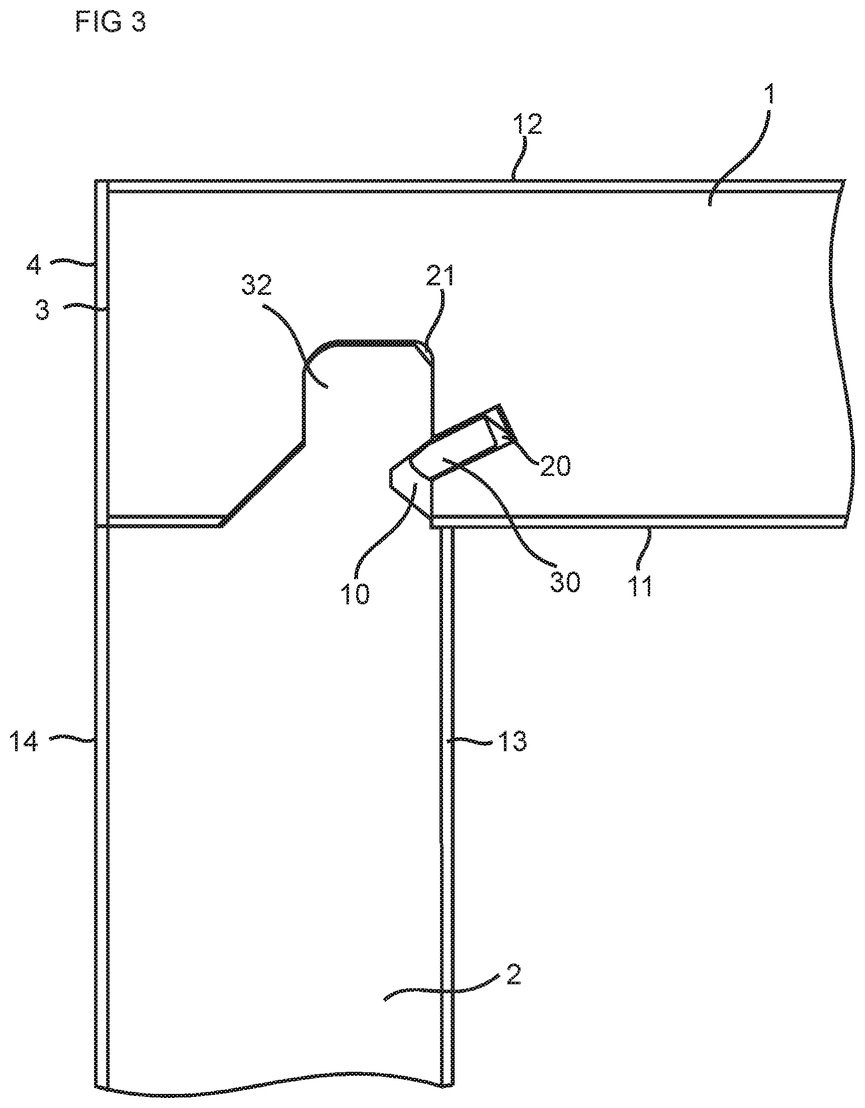
FIG. 3 shows an embodiment of a first panel, which may be produced according to an embodiment of the invention, locked together with an embodiment of a second panel
FIG. 4 shows an embodiment of a production line comprising a first edge machine and a fourth edge machine
FIG. 5 shows an embodiment of a production line.
DESCRIPTION OF EMBODIMENTS
Specific embodiments of the invention will now be described with reference to the accompanying drawings. This invention may, however, be embodied in many different forms and should not be construed as limited to the embodiments set forth herein; rather, these embodiments are provided so that this disclosure will be thorough and complete, and will fully convey the scope of the invention to those skilled in the art. The terminology used in the detailed description of the embodiments illustrated in the accompanying drawings is not intended to be limiting of the invention. In the drawings, like numbers refer to like elements.
Embodiments of the first panel are shown in FIGS. 1A-1C and FIGS. 2A-2D that may be produced according to embodiments of the invention.
FIG. 1A shows an embodiment of the first panel 1 in a 3D-view. FIG. 1B shows a top view and FIG. 1C shows a side view. The first panel comprises a first edge 3 comprising a first edge groove 21 and a second edge 5 comprising a second edge groove 22. The first edge groove extends along the whole first edge and comprises an opening at an adjacent third edge 7 and an opening at an adjacent fourth edge 6. The second edge groove extends along the whole second edge 5 and comprises an opening at the adjacent third edge 7 and an opening at the adjacent fourth edge 6. The first and the second edges are covered by a covering material. The first and the second edges 3,5 may be side edges of a furniture product and the fourth edge 6 may be a back edge. The third edge 7 may be a front edge that may be covered with a covering material (not shown) that covers the openings of the first edge groove and the second edge groove, respectively. The fourth edge 6 may comprise a third edge groove 23, which preferably ends at a distance 9 from the first edge and the second edge, respectively.
FIG. 2A shows an embodiment of the first panel 1 in a 3D-view. FIG. 2C shows a top view and FIG. 2B shows a side view. FIG. 2D shows a cross cut at the dotted line 24 shown in FIG. 2C.
The first panel comprises a first edge 3 comprising a first edge groove 21 and a second edge 5 comprising a second edge groove 22. The first edge groove extends along the first edge and comprises an opening at an adjacent fourth edge 6. The second edge groove extends along the second edge 5 and comprises an opening at the adjacent fourth edge 6. The first and the second edges are covered by a covering material. The first and the second edges 3,5 may be side edges of a furniture product and the fourth 6 edge may be a back edge. The first and the second edge groove may end at a distance 8 from the third edge 7. The fourth edge may comprise a third edge groove 23, which preferably ends at a distance 9 from the first edge and the second edge, respectively.
FIG. 3 shows an end piece of an embodiment of the first panel. The first panel 1 is locked together by a locking device to a second panel 2. A second main surface 13 of the second panel 2 is essentially perpendicular to a first main surface 11 of the first panel 1 in the shown locked position. The first edge groove 21 is configured to cooperate with an edge tongue 32 of the second panel 2 for locking the first panel 1 to the second panel 2 in a first direction, which is perpendicular to the second main surface 13 of the second panel. The locking device may comprise a flexible tongue 30, which may be arranged in an insertion groove 20 formed in the first edge groove 21, and a tongue groove 10 that may be formed in the edge tongue 32. The flexible tongue is configured to cooperate with the tongue groove for locking the first panel to the second panel in second direction which is perpendicular to the first main surface 11 of the first panel. The first panel 1 comprises a second main surface 12, which is opposite to the first main surface of the first panel. The second panel 2 comprises a first main surface 14, which opposite to the second main surface 13 of the second panel. The first edge 3 is covered by a covering material 4. The first and the second main surfaces of the first and the second panels may each be covered by a decorative layer. An outer surface of the covering material may be in line with an outer surface of the first main surface 14 of the second panel.
Another panel may be locked to the second edge groove of the first panel 1 in the same way as shown in FIG. 3.
Another panel may be locked also to the third edge groove of the first panel in the same way as shown in FIG. 3. For example, three panels may be locked to the first panel.
FIG. 4 shows an embodiment of a production line for producing embodiments of the first panel 1. The production line comprises a first edge machine 99. The first panel is formed by: displacing the first panel in a feeding direction 82 by a conveyor through a first edge machine 99, working, by a first tool 51 of the first edge machine 99, on a first edge 3 of the first panel to obtain a decided location of the first edge 3, attaching, by a second tool 52 of the first edge machine 99, a covering material 4, such as a laminate strip, a thermoplastic strip or a veneer strip, on the first edge 3, and forming a first edge groove 21, by a third tool 53 of the first edge machine 99, along the first edge 3 and on a first main surface 11 of the first panel 1.
The first panel may be positioned by a positioning device, such that the first panel is at a same position relative the conveyor at least between said attaching of the covering material by the second tool 52 and said forming of the first edge groove by the third tool 53. The positioning device may be a part protruding from the conveyor. The conveyor may comprise a lower chain track and an upper belt. The positioning device may protrude from the lower chain track. The first panel may be arranged with the first main surface facing the lower chain track. This may have the advantage that thickness variations of the first panel may not affect a location of the first edge groove relative the first main surface.
The working by the first tool 51 is performed before the attaching of the covering material 4 by the second tool 52, and the attaching of the covering material 4 by the second tool 52 is performed before the forming the first edge groove 21 by the third tool 53.
The forming of the first edge groove 21, by the third tool 53, may comprise mechanical cutting, such as milling.
The third tool may be displaced in a direction with an angle to the first main surface, the angle is may be an essentially right angle, e.g., about 90 degrees, such that the first edge groove ends at a distance 8 from a third edge 7, which is adjacent to the first edge 3. The direction is preferably perpendicular to an axis of rotation of the third tool.
An insertion groove 20 is formed, by a fourth tool 54 of the first edge machine 99, in the first edge groove 21. The forming may comprise displacing the fourth tool in a direction, which is preferably essentially perpendicular to an axis of rotation of the fourth tool, such that the insertion groove 20 ends at a distance from the third edge.
A tongue 30 is inserted, by a fifth tool 55 of the first machine, in the insertion groove 20.
A first tool setup comprising the first, second, third, fourth and fifth tools of the first edge machine are arranged on a first side 91 of the first edge machine 99. The shown first edge machine may comprise the same tool setup on a second side 92, which is opposite to the first side, for forming a second edge of the first panel.
Forming of a second edge at a second side 92 of the first edge machine may comprise: working, by a sixth tool 71 of the first edge machine 99, on a second edge 5 of the first panel to obtain a decided location of the second edge 5, which is opposite the first edge, attaching, by a seventh tool 72 of the first edge machine 99, a covering material, such as a laminate strip, a thermoplastic strip or a veneer strip, on the second edge 5, forming a second edge groove 22, by an eighth tool 73 of the first edge machine 99, along the second edge 5 and on the first main surface 11 of the first panel 1, wherein the second edge groove is configured to be a part of a locking device.
The forming may further comprise positioning of the first panel by a positioning device, such that the first panel is at a same position relative the conveyor at least between said attaching of the covering material by seventh tool 72 and said forming of the second edge groove by the eighth tool 73. The positioning device on the second side may be configured as on the first side.
The working by the sixth tool 71 is performed before the attaching of the covering material 4 by the seventh tool 72, and the attaching of the covering material 4 by the seventh tool 72 is performed before the forming the second edge groove 22 by the eighth tool 73.
The eighth tool may be displaced in a direction with an angle to the first main surface of the first panel, the angle is preferably an essentially right angle, e.g., about 90 degrees, such that the first edge groove ends at a distance 8 from a third edge 7, which is adjacent to the first edge 3. The direction is preferably perpendicular to an axis of rotation of the eighth tool.
The forming may comprise forming, by a ninth tool 74 of the first edge machine 99, an inserting groove 20 in the second edge groove 22. The forming may comprise displacing the ninth tool in a direction, which is preferably essentially perpendicular to an axis of rotation of the ninth tool, such that the inserting groove 20 ends at a distance from the third edge.
The forming may comprise inserting a tongue 30, by a tenth tool 75 of the first edge machine 99, in the inserting groove 20.
A second tool setup comprising the sixth, seventh, eighth, ninth and tenth tools of the first edge machine is arranged on the second side 92, which is opposite the first side, of the first edge machine 99.
The embodiment of the production line shown in FIG. 4 comprises a fourth edge machine 98 for forming a third and/or fourth edge 7, 6 of the first panel 1. An alternative embodiment of the production is lacking the fourth edge machine 98. The method for forming a third and/or fourth edge 7, 6 may for the alternative production line comprise the step of a feeding 84 the first panel from the outlet of the first edge machine, rotating the first panel 90 degrees, a feeding 86 into the inlet of the first edge machine and using the first and/or second tool setup for forming the third and/or fourth edge of the first panel. The width of the first edge machine may have to be adjusted before a forming of the third and/or fourth edge. Also the tools may have to be adjusted to another shape of the third and or fourth edge. In order to avoid adjustment it is therefore preferred to have the fourth edge machine 98 in the production line.
The forming of the first panel 1 may comprise: displacing the first panel 1 in a feeding direction 81 by a conveyor through a fourth edge machine 98, working, by a 11th tool 41 of the fourth edge machine 98, on a fourth edge 6 of the first panel to obtain a decided location of the fourth edge 6, wherein the fourth edge is adjacent the first edge 3, and forming a third edge groove 23, by a 13th tool 43 of the fourth edge machine 98, along the fourth edge 6 and on a first main surface 11 of the first panel 1, wherein the third edge groove is configured to be a part of a locking device.
The forming may further comprise displacing the 13th tool in a direction with an angle to the first main surface of the first panel, the angle is preferably an essentially right angle, e.g., about 90 degrees, such that the third edge groove ends at a distance 9 from the first edge 3 and at a distance from a second edge which is adjacent to the fourth edge 6. The direction is preferably perpendicular to an axis of rotation of the 13th tool.
The forming may further comprise: working, by a 16th tool 61 of a fourth edge machine 98, on a third edge 7 of the first panel to obtain a decided location of the third edge 7, which is adjacent the first edge 3, attaching, by a 17th tool 62 of the fourth edge machine 98, a covering material 4, such as a laminate strip, a thermoplastic strip or a veneer strip, on the third edge 7.
The fourth edge machine 98 may comprise a third tool setup, comprising the 11th tool and the 13th tool, that is arranged on a first side 93 of the fourth edge machine 98. The third tool set up may also comprise one or more of a 12th tool 42, a 14th tool 44 and a 15th tool 45, which corresponds to the second tool 52, the fourth tool 54 and a fifth tool 55, respectively, of the first tool setup. One or more of the tools of the third tool setup may be used for the forming of the fourth edge of the first panel.
The fourth edge machine 98 may comprise a fourth tool setup, comprising the 16th tool and the 17th tool, that is arranged on a second side 94, which is opposite the first side, of the fourth edge machine 98. The third tool set up may also comprise one or more of a 18th tool 63, a 19th tool 64 and a 20th tool 65, which corresponds to the eighth tool 73, the ninth tool 74 and a tenth tool 75, respectively, of the second tool setup. One or more of the tools of the fourth tool setup may be used for the forming of the third edge of the first panel.
The fourth edge machine 98 may comprise a positioning device on the first and the second side, such that the first panel is at a same position relative the conveyor during the forming. The positioning device may be a part protruding from the conveyor. The conveyor may comprise a lower chain track and an upper belt. The positioning device may protrude from the lower chain track. The fourth edge machine 98 may comprise a guiding device along the first and/or the second side, such that the third edge and the fourth edge are formed parallel.
An alternative production line shown in FIG. 5 which comprises a first machine 95, which comprises a tool set up that corresponds to the first tool setup of the first edge machine 99, and/or a second machine 96 with a tool setup that corresponds to second tool setup of the first edge machine 99. The first and the second machine may have a conveyor of the same type as the first edge machine.
The first panel 1 may be formed on the first edge 3 and the second edge 5 by displacing 81 the first panel through the first machine 9 and the second machine. The third edge and the fourth edge may be formed by displacing 87 the first panel from the outlet of the second machine to the inlet of the first machine and rotating 88 the first panel 90 degrees before beginning a forming of the third and the fourth edges.
Another embodiment of the alternative production line is lacking the second machine. The first edge may be formed by displacing 86 the first panel 1 through the first machine 95. The second edge may be formed by displacing 87 the first panel from the outlet of the first machine to the inlet of the first machine and rotating 88 the first panel 180 degrees before beginning a forming of the second edge. The third edge may be formed by displacing 89 the first panel from the outlet of the first machine to the inlet of the first machine and rotating 88 the first panel 90 degrees before beginning a forming of the third edge. The fourth edge may be formed by displacing 89 the first panel from the outlet of the first machine to the inlet of the first machine and rotating 88 the first panel 180 degrees before beginning a forming of the fourth edge.
An advantage with this alternative production line may be that an adjustment of the first and/or the second machine due to different widths of the first panel may not be needed. A disadvantage may be that the first panel may have to be displaced two or more times through the first and/or second machine.
One or more of the first tool, the fifth tool, 11th tool and the 16th tool may each comprise a mechanical cutting unit, such as a milling unit, and/or preferably a sanding unit.
One or more of the second tool, the seventh tool, the 12th tool and the 17th tool may each comprise a gluing section.
One or more of the third tool, the eighth tool, the 13th tool, the 18th tool and the 23th may each comprise a mechanical cutting unit, such as a milling unit, and/or preferably
The order of the any of the tools, and number of tools, in any of the toll setups may differ from each other, depending of the desired shapes of the first panel.
Forming of the first panel in any of the production lines described above may result in a same final shape of the first panel.
The furniture product may be a cabinet, such as a kitchen cabinet, bookshelves, a drawer, a table, a wardrobe or similar
The set of panels described above may be a part of a furniture product, such as a frame.
When the word "about" is used in this specification in connection with a numerical value, it is intended that the associated numerical value include a tolerance of .+-.10% around the stated numerical value.
EMBODIMENTS
1. A method for forming a first panel (1) for an assembled product, such as a furniture product, wherein the method comprises: displacing the first panel (1) in a feeding direction (82) by a conveyor through a first edge machine (99), working, by a first tool (51) of the first edge machine (99), on a first edge (3) of the first panel to obtain a decided location of the first edge (3), attaching, by a second tool (52) of the first edge machine (99), a covering material (4), such as a laminate strip, a thermoplastic strip or a veneer strip, on the first edge (3), and forming a first edge groove (21), by a third tool (53) of the first edge machine (99), along the first edge (3) and on a first main surface (11) of the first panel (1), wherein the first edge groove is configured to be a part of a locking device.
2. The method as in embodiment 1, wherein the method comprises positioning of the first panel by a positioning device, such that the first panel is at a same position relative the conveyor at least between said attaching of the covering material by the second tool (52) and said forming of the first edge groove by the third tool (53).
3. The method as in embodiment 1 or 2, wherein the working by the first tool (51) is performed before the attaching of the covering material (4) by the second tool (52), and the attaching of the covering material (4) by the second tool (52) is performed before the forming the first edge groove (21) by the third tool (53).
4. The method as in any one of the embodiments 1-3, wherein the method comprises forming, by a fourth tool (54) of the first edge machine (99), an inserting groove (20) in the first edge groove (21).
5. The method as in embodiment 4, wherein the method comprises inserting a tongue (30), by a fifth tool (55) of the first edge machine (99), in the inserting groove (20).
6. The method as in any one of the embodiments 1-6, wherein the method comprising displacing the third tool in a direction with an angle to the first main surface of the first panel, the angle is preferably an essentially right angle, such that the first edge groove ends at a distance (8) from a third edge (7), which is adjacent to the first edge (3).
7. The method as in any one of the embodiments 1-6, wherein the method comprises: working, by a sixth tool (71) of the first edge machine (99), on a second edge (5) of the first panel to obtain a decided location of the second edge (5), which is opposite the first edge, attaching, by a seventh tool (72) of the first edge machine (99), a covering material (4), such as a laminate strip, a thermoplastic strip or a veneer strip, on the second edge (5), forming a second edge groove (22), by an eighth tool (73) of the first edge machine (99), along the second edge (5) and on the first main surface (11) of the first panel (1), wherein the second edge groove is configured to be a part of a locking device.
8. The method as in embodiment 7, wherein the method comprises positioning of the first panel by a positioning device, such that the first panel is at a same position relative the conveyor at least between said attaching of the covering material by seventh tool (72) and said forming of the second edge groove by the eighth tool (73).
9. The method as in embodiment 7 or 8, wherein the working by the sixth tool (71) is performed before the attaching of the covering material (4) by the seventh tool (72), and the attaching of the covering material (4) by the seventh tool (72) is performed before the forming the second edge groove (22) by the eighth tool (73).
10. The method as in embodiment 7 or 8, wherein the method comprises forming, by a ninth tool (74) of the first edge machine (99), an inserting groove (20) in the second edge groove (22).
11. The method as in embodiment 10, wherein the method comprises inserting a tongue (30), by a tenth tool (75) of the first edge machine (99), in the inserting groove (20).
12. The method as in any one of the embodiments 7-11, wherein the method comprises displacing the eighth tool in a direction with an angle to the first main surface of the first panel, the angle is preferably an essentially right angle, such that the second edge groove ends at a distance (8) from a third edge (7), which is adjacent to the first edge (3).
13. The method as in any one of the embodiments 1-12, wherein the method comprises: displacing the first panel (1) in a feeding direction (81) by a conveyor through a fourth edge machine (98), working, by a 11th tool (41) of the fourth edge machine (98), on a fourth edge (6) of the first panel to obtain a decided location of the fourth edge (6), wherein the fourth edge is adjacent the first edge (3), and forming a third edge groove (23), by a 13th tool (43) of the fourth edge machine (98), along the fourth edge (6) and on a first main surface (11) of the first panel (1), wherein the third edge groove is configured to be a part of a locking device.
14. The method as in embodiment 13, wherein the method comprising displacing the 13th tool in a direction with an angle to the first main surface of the first panel, the angle is preferably an essentially right angle, such that the third edge groove ends at a distance (9) from the first edge (3) and at a distance from a second edge which is adjacent to the fourth edge (6).
15. The method as in any one of the embodiments 1-14, wherein the method comprises: working, by a 16th tool (61) of a fourth edge machine (98), on a third edge (7) of the first panel to obtain a decided location of the third edge (7), which is adjacent the first edge (3), attaching, by a 17th tool (62) of the fourth edge machine (98), a covering material (4), such as a laminate strip, a thermoplastic strip or a veneer strip, on the third edge (7).
* * * * *
D00000
D00001
D00002
D00003
D00004
D00005
XML
uspto.report is an independent third-party trademark research tool that is not affiliated, endorsed, or sponsored by the United States Patent and Trademark Office (USPTO) or any other governmental organization. The information provided by uspto.report is based on publicly available data at the time of writing and is intended for informational purposes only.
While we strive to provide accurate and up-to-date information, we do not guarantee the accuracy, completeness, reliability, or suitability of the information displayed on this site. The use of this site is at your own risk. Any reliance you place on such information is therefore strictly at your own risk.
All official trademark data, including owner information, should be verified by visiting the official USPTO website at www.uspto.gov. This site is not intended to replace professional legal advice and should not be used as a substitute for consulting with a legal professional who is knowledgeable about trademark law.