Gas delivery module
Khan , et al. A
U.S. patent number 10,748,783 [Application Number 16/510,847] was granted by the patent office on 2020-08-18 for gas delivery module. This patent grant is currently assigned to Applied Materials, Inc.. The grantee listed for this patent is Applied Materials, Inc.. Invention is credited to Adib M. Khan, Qiwei Liang, Sultan Malik, Srinivas D. Nemani.

| United States Patent | 10,748,783 |
| Khan , et al. | August 18, 2020 |
Gas delivery module
Abstract
The present disclosure relates to high pressure processing apparatus for semiconductor processing. The apparatus described herein include a high pressure process chamber and a containment chamber surrounding the process chamber. A high pressure fluid delivery module is in fluid communication with the high pressure process chamber and is configured to deliver a high pressure fluid to the process chamber.
| Inventors: | Khan; Adib M. (Santa Clara, CA), Liang; Qiwei (Fremont, CA), Malik; Sultan (Sacramento, CA), Nemani; Srinivas D. (Sunnyvale, CA) | ||||||||||
|---|---|---|---|---|---|---|---|---|---|---|---|
| Applicant: |
|
||||||||||
| Assignee: | Applied Materials, Inc. (Santa
Clara, CA) |
||||||||||
| Family ID: | 69178620 | ||||||||||
| Appl. No.: | 16/510,847 | ||||||||||
| Filed: | July 12, 2019 |
Prior Publication Data
| Document Identifier | Publication Date | |
|---|---|---|
| US 20200035509 A1 | Jan 30, 2020 | |
Related U.S. Patent Documents
| Application Number | Filing Date | Patent Number | Issue Date | ||
|---|---|---|---|---|---|
| 62703251 | Jul 25, 2018 | ||||
| Current U.S. Class: | 1/1 |
| Current CPC Class: | H01L 21/67017 (20130101); C23C 16/452 (20130101); H01L 21/67011 (20130101); H01L 21/6719 (20130101); H01L 21/67126 (20130101); H01L 21/447 (20130101) |
| Current International Class: | H01L 21/00 (20060101); C23C 16/452 (20060101); H01L 21/447 (20060101); H01L 21/67 (20060101) |
References Cited [Referenced By]
U.S. Patent Documents
| 4524587 | June 1985 | Kantor |
| 4879259 | November 1989 | Reynolds et al. |
| 5050540 | September 1991 | Lindberg |
| 5114513 | May 1992 | Hosokawa et al. |
| 5126117 | June 1992 | Schumacher et al. |
| 5149378 | September 1992 | Ohmi et al. |
| 5175123 | December 1992 | Vasquez et al. |
| 5319212 | June 1994 | Tokoro |
| 5366905 | November 1994 | Mukai |
| 5578132 | November 1996 | Yamaga et al. |
| 5590695 | January 1997 | Siegele et al. |
| 5620524 | April 1997 | Fan et al. |
| 5808245 | September 1998 | Wiese et al. |
| 5858051 | January 1999 | Komiyama et al. |
| 5879756 | March 1999 | Fathi et al. |
| 5880041 | March 1999 | Ong |
| 5940985 | August 1999 | Kamikawa et al. |
| 6082950 | July 2000 | Altwood et al. |
| 6136664 | October 2000 | Economikos et al. |
| 6150286 | November 2000 | Sun et al. |
| 6164412 | December 2000 | Allman |
| 6242368 | June 2001 | Holmer et al. |
| 6251751 | June 2001 | Chu et al. |
| 6299753 | October 2001 | Chao et al. |
| 6319766 | November 2001 | Bakli et al. |
| 6334266 | January 2002 | Moritz et al. |
| 6368412 | April 2002 | Gomi |
| 6442980 | September 2002 | Preston et al. |
| 6468490 | October 2002 | Shamouilian et al. |
| 6500603 | December 2002 | Shioda |
| 6583497 | June 2003 | Xia et al. |
| 6619304 | September 2003 | Worm |
| 6797336 | September 2004 | Garvey et al. |
| 7055333 | June 2006 | Leitch et al. |
| 7084079 | August 2006 | Conti et al. |
| 7111630 | September 2006 | Mizobata et al. |
| 7114517 | October 2006 | Sund et al. |
| 7211525 | May 2007 | Shanker et al. |
| 7282458 | October 2007 | Gates et al. |
| 7361231 | April 2008 | Fury et al. |
| 7460760 | December 2008 | Cho et al. |
| 7491658 | February 2009 | Nguyen et al. |
| 7503334 | March 2009 | Shrinivasan et al. |
| 7521089 | April 2009 | Hillman et al. |
| 7521378 | April 2009 | Fucsko et al. |
| 7541297 | June 2009 | Mallick et al. |
| 7576441 | August 2009 | Yin et al. |
| 7650965 | January 2010 | Thayer et al. |
| 7651959 | January 2010 | Fukazawa et al. |
| 7655532 | February 2010 | Chen et al. |
| 7825038 | November 2010 | Ingle et al. |
| 7825042 | November 2010 | Mandal |
| 7867923 | January 2011 | Mallick et al. |
| 7891228 | February 2011 | Ding et al. |
| 8027089 | September 2011 | Hayashi |
| 8306026 | November 2012 | Anjum et al. |
| 8318584 | November 2012 | Li et al. |
| 8349085 | January 2013 | Tahara et al. |
| 8449942 | May 2013 | Li et al. |
| 8455368 | June 2013 | Chandler et al. |
| 8466073 | June 2013 | Wang et al. |
| 8481123 | July 2013 | Kim et al. |
| 8536065 | September 2013 | Seamons et al. |
| 8557712 | October 2013 | Antonelli et al. |
| 8563445 | October 2013 | Liang et al. |
| 8647992 | February 2014 | Liang et al. |
| 8741788 | June 2014 | Liang et al. |
| 8871656 | October 2014 | Mallick et al. |
| 8906761 | December 2014 | Kim et al. |
| 8936834 | January 2015 | Kim et al. |
| 9121515 | September 2015 | Yamamoto et al. |
| 9153442 | October 2015 | Wang et al. |
| 9157730 | October 2015 | Rajagopalan et al. |
| 9257314 | February 2016 | Rivera et al. |
| 9306026 | April 2016 | Toriumi et al. |
| 9362107 | June 2016 | Thadani et al. |
| 9382621 | July 2016 | Choi |
| 9484406 | November 2016 | Sun et al. |
| 9570551 | February 2017 | Balakrishnan et al. |
| 10083834 | September 2018 | Thompson et al. |
| 10096516 | October 2018 | Leschkies et al. |
| 10276411 | April 2019 | Delmas et al. |
| 2001/0029108 | October 2001 | Tometsuka |
| 2001/0041122 | November 2001 | Kroeker |
| 2001/0050096 | December 2001 | Costantini et al. |
| 2002/0066535 | June 2002 | Brown et al. |
| 2002/0073922 | June 2002 | Frankel et al. |
| 2002/0122885 | September 2002 | Ahn |
| 2002/0134439 | September 2002 | Kawasaki et al. |
| 2002/0148492 | October 2002 | Yamagata et al. |
| 2002/0151128 | October 2002 | Lane et al. |
| 2002/0155714 | October 2002 | Suzuki |
| 2003/0030945 | February 2003 | Heinonen et al. |
| 2003/0049372 | March 2003 | Cook et al. |
| 2003/0101938 | June 2003 | Ronsse et al. |
| 2003/0148035 | August 2003 | Lingampalli |
| 2003/0148631 | August 2003 | Kuo et al. |
| 2003/0207593 | November 2003 | Derderian et al. |
| 2004/0025908 | February 2004 | Douglas et al. |
| 2004/0060519 | April 2004 | Beauchaine et al. |
| 2004/0074869 | April 2004 | Wang et al. |
| 2004/0112409 | June 2004 | Schilling |
| 2004/0219800 | November 2004 | Tognetti |
| 2004/0248392 | December 2004 | Narwankar et al. |
| 2005/0003655 | January 2005 | Cathey et al. |
| 2005/0051194 | March 2005 | Sakashita et al. |
| 2005/0136684 | June 2005 | Mukai et al. |
| 2005/0191828 | September 2005 | Ai-Bayati et al. |
| 2005/0198971 | September 2005 | Leitch et al. |
| 2005/0250347 | November 2005 | Bailey et al. |
| 2005/0269291 | December 2005 | Kent |
| 2006/0003596 | January 2006 | Fucsko et al. |
| 2006/0105107 | May 2006 | Lindeboom et al. |
| 2006/0124613 | June 2006 | Kumar et al. |
| 2006/0175012 | August 2006 | Lee |
| 2006/0207633 | September 2006 | Kim et al. |
| 2006/0226117 | October 2006 | Bertram et al. |
| 2006/0279025 | December 2006 | Heidari et al. |
| 2006/0290017 | December 2006 | Yanagisawa |
| 2007/0012402 | January 2007 | Sneh |
| 2007/0045753 | March 2007 | Pae et al. |
| 2007/0187386 | August 2007 | Kim et al. |
| 2007/0204797 | September 2007 | Fischer |
| 2007/0212850 | September 2007 | Ingle et al. |
| 2007/0243317 | October 2007 | Du Bois et al. |
| 2007/0256559 | November 2007 | Chen et al. |
| 2008/0074658 | March 2008 | Davis et al. |
| 2008/0083109 | April 2008 | Shibata et al. |
| 2008/0115726 | May 2008 | Ingle et al. |
| 2008/0121882 | May 2008 | Hwang et al. |
| 2008/0210273 | September 2008 | Joe |
| 2008/0251904 | October 2008 | Theuss et al. |
| 2009/0018688 | January 2009 | Chandler et al. |
| 2009/0081884 | March 2009 | Yokota et al. |
| 2009/0110622 | April 2009 | Chiu et al. |
| 2009/0148965 | June 2009 | Kim et al. |
| 2009/0180847 | July 2009 | Guo et al. |
| 2009/0186481 | July 2009 | Suzuki et al. |
| 2009/0233449 | September 2009 | Lebouitz et al. |
| 2009/0243126 | October 2009 | Washiya et al. |
| 2010/0006211 | January 2010 | Wolk et al. |
| 2010/0012292 | January 2010 | Yamazaki |
| 2010/0022068 | January 2010 | Chen et al. |
| 2010/0173495 | July 2010 | Thakur et al. |
| 2010/0196626 | August 2010 | Choi |
| 2010/0304027 | December 2010 | Lee et al. |
| 2010/0320459 | December 2010 | Umeda et al. |
| 2010/0327422 | December 2010 | Lee et al. |
| 2011/0151677 | June 2011 | Wang et al. |
| 2011/0165781 | July 2011 | Liang et al. |
| 2011/0198736 | August 2011 | Shero et al. |
| 2012/0048304 | March 2012 | Kitajima et al. |
| 2012/0056173 | March 2012 | Pieralisi |
| 2012/0060868 | March 2012 | Gray |
| 2012/0142192 | June 2012 | Li et al. |
| 2012/0175822 | July 2012 | Inamiya et al. |
| 2012/0252210 | October 2012 | Tohnoe |
| 2012/0285492 | November 2012 | Lee et al. |
| 2012/0304485 | December 2012 | Hayashi et al. |
| 2013/0194350 | August 2013 | Watanabe et al. |
| 2013/0233170 | September 2013 | Spiegelman et al. |
| 2013/0288485 | October 2013 | Liang et al. |
| 2013/0302916 | November 2013 | Kim et al. |
| 2013/0330042 | December 2013 | Nara et al. |
| 2013/0337171 | December 2013 | Sasagawa |
| 2014/0023320 | January 2014 | Lee et al. |
| 2014/0045300 | February 2014 | Chen et al. |
| 2014/0076494 | March 2014 | Miyashita et al. |
| 2014/0134827 | May 2014 | Swaminathan et al. |
| 2014/0138802 | May 2014 | Starostine et al. |
| 2014/0183743 | July 2014 | Matsumoto et al. |
| 2014/0231384 | August 2014 | Underwood et al. |
| 2014/0235068 | August 2014 | Ashihara et al. |
| 2014/0239291 | August 2014 | Son et al. |
| 2014/0264237 | September 2014 | Chen et al. |
| 2014/0268080 | September 2014 | Beasley et al. |
| 2014/0284821 | September 2014 | Hubbard |
| 2014/0322921 | October 2014 | Ahmad et al. |
| 2015/0000870 | January 2015 | Hosotani et al. |
| 2015/0050807 | February 2015 | Wu et al. |
| 2015/0056819 | February 2015 | Wong et al. |
| 2015/0091009 | April 2015 | Yamazaki et al. |
| 2015/0099342 | April 2015 | Tsai et al. |
| 2015/0159272 | June 2015 | Yoon et al. |
| 2015/0179501 | June 2015 | Jhaveri et al. |
| 2015/0255581 | September 2015 | Lin et al. |
| 2015/0292736 | October 2015 | Hirson et al. |
| 2015/0309073 | October 2015 | Mirkin et al. |
| 2015/0322286 | November 2015 | Cabrini et al. |
| 2015/0364348 | December 2015 | Park et al. |
| 2016/0027887 | January 2016 | Yuan et al. |
| 2016/0035600 | February 2016 | Rivera et al. |
| 2016/0064209 | March 2016 | Lee et al. |
| 2016/0064482 | March 2016 | Hashemi et al. |
| 2016/0076149 | March 2016 | Yamazaki et al. |
| 2016/0086831 | March 2016 | Rivera et al. |
| 2016/0111272 | April 2016 | Girard et al. |
| 2016/0118391 | April 2016 | Zhao et al. |
| 2016/0163540 | June 2016 | Liao et al. |
| 2016/0208414 | July 2016 | Odawara et al. |
| 2016/0260526 | September 2016 | Otto |
| 2016/0273758 | September 2016 | Fujimura |
| 2016/0274454 | September 2016 | Beasley et al. |
| 2016/0314964 | October 2016 | Tang et al. |
| 2016/0334162 | November 2016 | Kim et al. |
| 2016/0336405 | November 2016 | Sun et al. |
| 2016/0353522 | December 2016 | Rathi et al. |
| 2017/0005204 | January 2017 | Hosoba et al. |
| 2017/0011932 | January 2017 | Pethe et al. |
| 2017/0084487 | March 2017 | Chebiam et al. |
| 2017/0104062 | April 2017 | Bi et al. |
| 2017/0140996 | May 2017 | Lin et al. |
| 2017/0160012 | June 2017 | Kobayashi et al. |
| 2017/0162413 | June 2017 | Rebstock |
| 2017/0194430 | July 2017 | Wood et al. |
| 2017/0253968 | September 2017 | Yahata |
| 2017/0263702 | September 2017 | Chan et al. |
| 2017/0314125 | November 2017 | Fenwick et al. |
| 2017/0358483 | December 2017 | Roy et al. |
| 2018/0019249 | January 2018 | Zhang et al. |
| 2018/0023192 | January 2018 | Chandra et al. |
| 2018/0087418 | March 2018 | Cadigan |
| 2018/0261480 | September 2018 | Liang et al. |
| 2018/0286674 | October 2018 | Manna et al. |
| 2018/0315626 | November 2018 | Franklin |
| 2018/0337027 | November 2018 | L'Heureux et al. |
| 2018/0342384 | November 2018 | Wong et al. |
| 2018/0350563 | December 2018 | Manna et al. |
| 2019/0057879 | February 2019 | Delmas et al. |
| 2019/0119769 | April 2019 | Khan et al. |
| 2019/0139793 | May 2019 | Delmas et al. |
| 2019/0148178 | May 2019 | Liang et al. |
| 2019/0148186 | May 2019 | Schaller et al. |
| 2019/0157074 | May 2019 | Delmas |
| 2019/0228982 | July 2019 | Chen et al. |
| 2019/0237345 | August 2019 | Delmas et al. |
| 2019/0258153 | August 2019 | Nemani et al. |
| 2019/0259625 | August 2019 | Nemani et al. |
| 2019/0279879 | September 2019 | Singh et al. |
| 2019/0311896 | October 2019 | Balseanu et al. |
| 2019/0368035 | December 2019 | Malik et al. |
| 2020/0035513 | January 2020 | Khan et al. |
| 2020/0098574 | March 2020 | Wong et al. |
| 101871043 | Oct 2010 | CN | |||
| 104047676 | Sep 2014 | CN | |||
| 104089491 | Oct 2014 | CN | |||
| 63-004616 | Jan 1988 | JP | |||
| 06-283496 | Oct 1994 | JP | |||
| H07048489 | May 1995 | JP | |||
| 2001110729 | Apr 2001 | JP | |||
| 2003-51474 | Feb 2003 | JP | |||
| 2004127958 | Apr 2004 | JP | |||
| 2005064269 | Mar 2005 | JP | |||
| 2005-333015 | Dec 2005 | JP | |||
| 2007242791 | Sep 2007 | JP | |||
| 2008/073611 | Apr 2008 | JP | |||
| 2009-129927 | Jun 2009 | JP | |||
| 2010-205854 | Sep 2010 | JP | |||
| 2012-503883 | Feb 2012 | JP | |||
| 2012-204656 | Oct 2012 | JP | |||
| 2013-105777 | May 2013 | JP | |||
| 2013516788 | May 2013 | JP | |||
| 2013-179244 | Sep 2013 | JP | |||
| 2014019912 | Feb 2014 | JP | |||
| 20030052162 | Jun 2003 | KR | |||
| 20070075383 | Jul 2007 | KR | |||
| 20090011463 | Feb 2009 | KR | |||
| 1020090040867 | Apr 2009 | KR | |||
| 10-2009-0064279 | Jun 2009 | KR | |||
| 10-2010-0035000 | Apr 2010 | KR | |||
| 20110136532 | Dec 2011 | KR | |||
| 101287035 | Jul 2013 | KR | |||
| 101305904 | Sep 2013 | KR | |||
| 20140003776 | Jan 2014 | KR | |||
| 20140135744 | Nov 2014 | KR | |||
| 20150006587 | Jan 2015 | KR | |||
| 20150122432 | Nov 2015 | KR | |||
| 200529284 | Sep 2005 | TW | |||
| 200721316 | Jun 2007 | TW | |||
| 201507174 | Feb 2015 | TW | |||
| 2005057663 | Jun 2005 | WO | |||
| 2008/089178 | Jul 2008 | WO | |||
| 2011/103062 | Aug 2011 | WO | |||
| 2012/133583 | Oct 2012 | WO | |||
| 2016/018593 | Feb 2016 | WO | |||
| 2016065219 | Apr 2016 | WO | |||
Other References
|
International Search Report and Written Opinion for PCT/US2018/050464 dated Jan. 4, 2019. cited by applicant . International Search Report and Written Opinion for PCT/US2019/056447 dated Feb. 7, 2020. cited by applicant . KR Office Action dated Feb. 4, 2020 for Application No. 10-2018-0133399. cited by applicant . Taiwan Office Action dated Feb. 21, 2020 for Application No. 108138212. cited by applicant . International Search Report and Written Opinion for International Application No. PCT/US2019/059659 dated Feb. 26, 2020. cited by applicant . Office Action from Taiwan Patent Application No. 108104585 dated Jan. 30, 2020, with concise statement of relevance. cited by applicant . Pedestal definition from Dictionary.com, printed on Feb. 10, 2020 (year 2020). cited by applicant . International Search Report and Written Opinion for International Application No. PCT/US2019/040195 dated Oct. 25, 2019. cited by applicant . Taiwan Office Action dated Nov. 19, 2019 for Application No. 108103415. cited by applicant . Office Action for Japanese Application No. 2018-517285 dated Oct. 23, 2019. cited by applicant . Office Action for Taiwan Patent Application No. 108111501 dated Nov. 14, 2019. cited by applicant . Taiwan Office Action dated Jun. 11, 2019 for Application No. 107138905. cited by applicant . International Search Report and Written Opinion for International Application No. PCT/US2019/029602 dated Aug. 14, 2019. cited by applicant . Haskel Pressure on Demand, Pneumatic and Hydraulic Driven Gas Boosters, Apr. 30, 2016, 36 pp. cited by applicant . International Search Report and Written Opinion for PCT/US2018/021715 dated Jun. 22, 2018. cited by applicant . International Search Report and Written Opinion from PCT/US2018/034036 dated Aug. 24, 2018. cited by applicant . International Search Report and Written Opinion dated Aug. 24, 2018 for Application No. PCT/US2018/034284. cited by applicant . International Search Report, Application No. PCT/US2018/028258 dated Aug. 9, 2018. cited by applicant . International Search Report and Written Opinion for PCT/US2018/035210 dated Aug. 24, 2018. cited by applicant . International Search Report and Written Opinion for PCT/US2018/037539 dated Oct. 5, 2018. cited by applicant . International Search Report and Written Opinion for PCT/US2018/038822 dated Oct. 26, 2018. cited by applicant . Chen, Yang et al., "Analysis of Supercritical Carbon Dioxide Heat Exchangers in Cooling Process", International Refrigeration and Air Conditioning Conference at Purdue, Jul. 17-20, 2006, pp. 1-8. cited by applicant . Shimoyama, Takehiro et al., "Porous Aluminum for Heat Exchanger", Hitachi Chemical, pp. 19-20. cited by applicant . Kato, T. et al., "Heat Transfer Characteristics of a Plate-Fin Type Supercritical/Liquid Helium Heat Exchanger", ICEC 14 Proceedings Supplement, 1992, pp. 260-263. cited by applicant . Lee, Ho-Saeng et al., "The cooling heat transfer characteristics of the supercritical CO2 in mico-fin tube", Springer, Oct. 2, 2012, pp. 173-184. cited by applicant . International Search Report and Written Opinion dated Nov. 30, 2018 for Application No. PCT/US2018/041688. cited by applicant . International Search Report and Written Opinion for PCT/US2018/043160 dated Jan. 31, 2019. cited by applicant . International Search Report and Written Opinion dated Jan. 31, 2019 for Application No. PCT/US2018/042760. cited by applicant . International Search Report and Written Opinion for PCT/US2018/059643 dated Feb. 26, 2019. cited by applicant . International Search Report and Written Opinion from PCT/US2019/012161 dated Apr. 30, 2019. cited by applicant . International Search Report and Written Opinion for PCT/US2019/014759 dated May 14, 2019. cited by applicant . International Search Report and Written Opinion for PCT/US2019/015332 dated May 15, 2019. cited by applicant . International Search Report and Written Opinion for PCT/US2018/059676 dated May 23, 2019. cited by applicant . International Search Report and Written Opinion for PCT/US2019/023431 dated Jul. 5, 2019. cited by applicant . Taiwan Office Action dated Jul. 3, 2019 for Application No. 107136181. cited by applicant . Office Action for Japanese Application No. 2018-546484 dated Oct. 8, 2019. cited by applicant. |
Primary Examiner: Yushin; Nikolay K
Attorney, Agent or Firm: Patterson + Sheridan, LLP
Parent Case Text
CROSS-REFERENCE TO RELATED APPLICATIONS
This application claims benefit of U.S. Provisional Patent Application No. 62/703,251, filed Jul. 25, 2018, the entirety of which is hereby incorporated by reference.
Claims
What is claimed is:
1. A high pressure processing apparatus, comprising: a first chamber body defining a first volume therein; a second chamber body disposed within the first volume, the second chamber body defining a second volume therein; a fluid delivery module in fluid communication with the second volume, the fluid delivery module comprising: a first reservoir; a first conduit extending between the first reservoir and the second volume; a flow regulator disposed on the first conduit; a second reservoir in fluid communication with a plurality of gas pumps, wherein the plurality of gas pumps are operable to pressurize a fluid in a graduated manner and deliver the pressurized fluid to the second reservoir; and a second conduit extending between the second reservoir and the second volume.
2. The apparatus of claim 1, wherein the plurality of gas pumps and the second reservoir are operable at pressures greater than about 50 bar.
3. The apparatus of claim 1, further comprising: an enclosure containing the first reservoir, the second reservoir, and the plurality of gas pumps therein.
4. The apparatus of claim 1, wherein the graduated pressurization is a staged pressure increase.
5. The apparatus of claim 1, wherein the plurality of gas pumps comprise a first gas pump and a second gas pump positioned in series to decrease a ramp time associated with pressurization of the fluid.
6. The apparatus of claim 1, wherein the first reservoir and the plurality of gas pumps are fabricated from a nickel containing steel alloy.
7. The apparatus of claim 6, wherein the nickel containing steel alloy comprises molybdenum.
8. The apparatus of claim 7, wherein the nickel containing steel alloy comprises chromium.
9. The apparatus of claim 1, wherein the first volume defined by the first chamber body is between about 80 L and about 150 L.
10. The apparatus of claim 9, wherein the second volume defined by the second chamber body is between about 3 L and about 8 L.
11. A high pressure processing apparatus, comprising: a first chamber body defining a first volume therein; a second chamber body disposed within the first volume, the second chamber body defining a second volume therein; a fluid delivery module in fluid communication with the second volume, the fluid delivery module comprising: a first reservoir; a first conduit extending between the first reservoir and the second volume; a flow regulator disposed on the first conduit; a second reservoir in fluid communication with a plurality of gas pumps; a second conduit extending between the second reservoir and the second volume; a first valve disposed on the first conduit; a second valve disposed on the second conduit; and a third valve disposed on the second conduit between the second valve and the first chamber body.
12. The apparatus of claim 11, wherein the second conduit is disposed within a heater jacket, the heater jacket being operable to maintain a temperature of the second conduit at a temperature greater than about 350.degree. C.
13. The apparatus of claim 11, further comprising: an enclosure containing the first reservoir, the second reservoir, and the plurality of gas pumps therein.
14. A high pressure processing apparatus, comprising: an enclosure defining a volume therein; a first reservoir disposed within the volume, the first reservoir comprising: a fluid inlet port; a first fluid outlet port; and a second fluid outlet port; a second reservoir disposed within the volume, the second reservoir comprising: a fluid inlet port; and a fluid outlet port; a first gas pump; a second gas pump disposed between the first gas pump and the second reservoir; and a conduit extending between the second gas pump and the second reservoir.
15. The apparatus of claim 14, wherein the enclosure further comprises: a fluid inlet port; and an exhaust port.
16. The apparatus of claim 14, wherein the second reservoir, the first gas pump, and the second gas pump are fabricated from a nickel containing steel alloy.
17. The apparatus of claim 16, wherein the nickel containing steel alloy comprises molybdenum.
18. The apparatus of claim 17, wherein the nickel containing steel alloy comprises chromium.
19. A high pressure processing apparatus, comprising: a first chamber body defining a first volume therein; a first slit valve door coupled to an external surface of the first chamber body; a second chamber body disposed within the first volume, the second chamber body defining a second volume therein; a second slit valve door coupled to an interior surface of the second chamber body; a fluid delivery module in fluid communication with the second volume via a plurality of conduits, the fluid delivery module comprising: a first reservoir in fluid communication with the second volume via a first conduit of the plurality; a flow regulator disposed on the first conduit between the first reservoir and the second volume; a second reservoir comprising a fluid inlet port and a fluid outlet port, the second reservoir fabricated from a nickel containing steel alloy in fluid communication with the second volume via a second conduit; a first gas pump fabricated from the nickel containing steel alloy; and a second gas pump fabricated from the nickel containing steel alloy, the second gas pump in fluid communication with each of the first gas pump and the second reservoir.
20. The apparatus of claim 19, wherein the first reservoir further comprises: a fluid inlet port; a first fluid outlet port; and a second fluid outlet port.
Description
BACKGROUND
Field
Embodiments of the present disclosure generally relate to apparatus for semiconductor processing. More specifically, embodiments of the disclosure relate to a high pressure gas delivery module.
Description of the Related Art
The field of semiconductor manufacturing utilizes various processes to fabricate devices which are incorporated into integrated circuits. As device complexity increases, integrated circuit manufacturers look for improved methodologies to fabricate advanced node devices. For example, advanced processing characteristics may include the utilization of more extreme process variables to enable advanced device fabrication.
One example of a process variable which is increasingly being investigated for utilization in semiconductor manufacturing is high pressure processing. High pressure processing at pressures elevated above atmospheric pressure has shown promising material modulation characteristics. However, apparatus suitable for safely and efficiently performing high pressure processing is often lacking when considering the requisite degree of control desired to perform advanced node device fabrication processes.
Accordingly, what is needed in the art are improved high pressure processing apparatus and methods for performing high pressure processing.
SUMMARY
In one embodiment, a high pressure processing apparatus is provided. The apparatus includes a first chamber body defining a first volume therein. A second chamber body is disposed within the first volume and the second chamber body defines a second volume therein. A fluid delivery module is in fluid communication with the second volume. The fluid delivery module includes a first reservoir, a first conduit extending between the first reservoir and the second volume, a flow regulator disposed on the first conduit, a second reservoir in fluid communication with a plurality of gas pumps, and a second conduit extending between the second reservoir and the second volume.
In another embodiment, a high pressure processing apparatus is provided. The apparatus includes an enclosure defining a volume therein and a first reservoir disposed within the volume. The first reservoir includes a fluid inlet port, a first fluid outlet port, and a second fluid outlet port. A second reservoir is disposed within the volume and the second reservoir includes a fluid inlet port and a fluid outlet port. The apparatus further includes a first gas pump, a second gas pump disposed between the first gas pump and the second reservoir, and a conduit extending between the second gas pump and the second reservoir.
In yet another embodiment, a high pressure processing apparatus is provided. The apparatus includes a first chamber body defining a first volume therein, a first slit valve door coupled to an external surface of the first chamber body, a second chamber body disposed within the first volume, the second chamber body defining a second volume therein, and a second slit valve door coupled to an interior surface of the second chamber body. A fluid delivery module is in fluid communication with the second volume via a plurality of conduits. The fluid delivery module includes a first reservoir in fluid communication with the second volume via a first conduit of the plurality, a second reservoir fabricated from a nickel containing steel alloy in fluid communication with the second volume via a second conduit, a first gas pump fabricated from the nickel containing steel alloy, and a second gas pump fabricated from the nickel containing steel alloy. The second gas pump is in fluid communication with each of the first gas pump and the second reservoir.
BRIEF DESCRIPTION OF THE DRAWINGS
So that the manner in which the above recited features of the present disclosure can be understood in detail, a more particular description of the disclosure, briefly summarized above, may be had by reference to embodiments, some of which are illustrated in the appended drawings. It is to be noted, however, that the appended drawings illustrate only exemplary embodiments and are therefore not to be considered limiting of its scope, may admit to other equally effective embodiments.
FIG. 1 is a schematic illustration of a high pressure processing apparatus according to an embodiment described herein.
FIG. 2 is a schematic illustration of a fluid delivery module according to an embodiment described herein.
To facilitate understanding, identical reference numerals have been used, where possible, to designate identical elements that are common to the figures. It is contemplated that elements and features of one embodiment may be beneficially incorporated in other embodiments without further recitation.
DETAILED DESCRIPTION
Embodiments of the present disclosure relate to high pressure processing apparatus for semiconductor processing. The apparatus described herein include a high pressure process chamber and a containment chamber surrounding the process chamber. A high pressure fluid delivery module is in fluid communication with the high pressure process chamber and is configured to deliver a high pressure fluid to the process chamber.
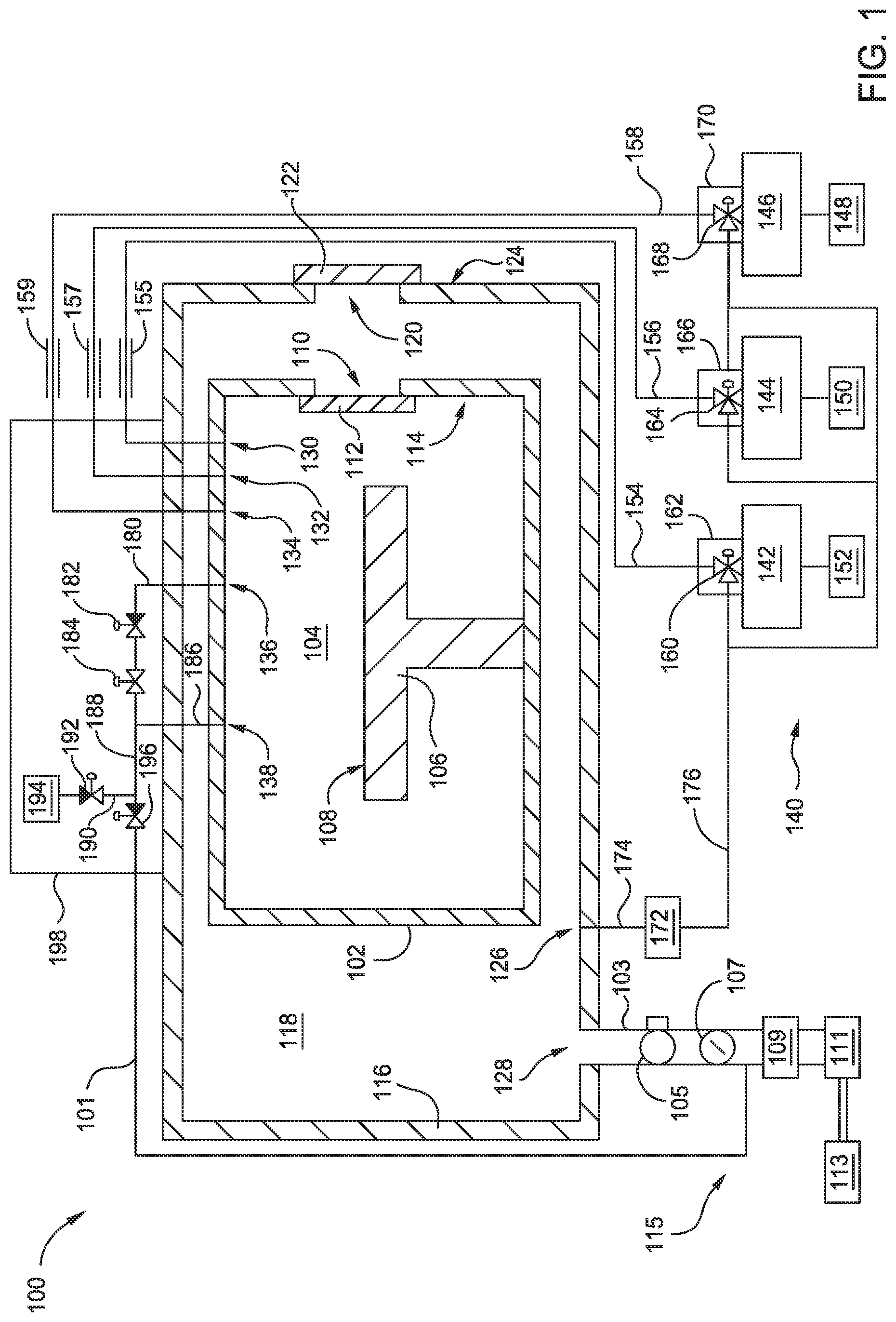
FIG. 1 is a schematic illustration of a high pressure processing apparatus 100 according to an embodiment described herein. The apparatus 100 includes a first chamber 116 which defines a first volume 118 therein. In one embodiment, a volume of the first volume 118 is between about 80 liters and about 150 liters, for example, between about 100 liters and about 120 liters. The first chamber 116 is fabricated from a process compatible material, such as aluminum, stainless steel, alloys thereof, and combinations thereof. In one embodiment, the first chamber 116 is fabricated from a nickel containing steel alloy, for example, a nickel molybdenum containing steel alloy or a nickel chromium molybdenum containing steel alloy. The material selected for fabrication of the first chamber 116 is suitable for operation at sub-atmospheric pressures, for example pressures less than about 700 Torr, such as 650 Torr or less.
The first chamber 116 has an exhaust port 128 formed therein. An exhaust conduit 103 is coupled to the first chamber 116 at the exhaust port 128 such that the exhaust conduit 103 is in fluid communication with the first volume 118. An isolation valve 105 and a throttle valve 107 are disposed on the exhaust conduit 103. The isolation valve 105 is disposed on the exhaust conduit 103 between the throttle valve 107 and the exhaust port 128. The isolation valve 105 is operable to initiate and extinguish fluid communication between the first volume 118 and an exhaust 113. The throttle valve 107 controls a flow rate of effluent flowing through the exhaust conduit 103 from the first volume 118.
A pump 109 is also coupled to the exhaust conduit 103 and the pump 109 operates to pull fluid from the first volume 118 to the exhaust 113. The pump 109 is disposed on exhaust conduit 103 between the throttle valve 107 and the exhaust 113. In one embodiment, the pump 109 generates a sub-atmospheric pressure in the first volume 118, such as a pressure less than about 700 Torr. A scrubber 111 is also disposed on the exhaust conduit 103 between the pump 109 and the exhaust 113. The scrubber 111 is in fluid communication with the first volume 118 via the exhaust conduit 103 and the scrubber 111 is configured to treat effluent from the first volume 118 prior to the effluent exiting the exhaust conduit 103 to the exhaust 113.
The first chamber 116 has an external surface 124 which is not exposed to the first volume 118. A first slit valve 120 is formed in the chamber 116 to enable ingress and egress of a substrate therethrough. A first slit valve door 122 is coupled to the external surface 124 adjacent to the first slit valve 120. In operation, the first slit valve door 122 is opened to enable passage of the substrate therethrough and closes prior to processing of the substrate.
A second chamber 102 is disposed within the first volume 118 defined by the first chamber 116. The second chamber 102 defines a second volume 104 therein. Similar to the first chamber 116, the second chamber 102 is fabricated from a process compatible material, such as aluminum, stainless steel, alloys thereof, and combinations thereof. In one embodiment, the second chamber 102 is fabricated from a nickel containing steel alloy, for example, a nickel molybdenum containing steel alloy or a nickel chromium molybdenum containing steel alloy. The material selected for fabrication of the second chamber 102 is suitable for operation of the second volume 104 at high pressures, such as greater than about 30 bar, for example, about 50 bar or greater.
A pedestal 106 is disposed in the second chamber 102 and the pedestal 106 has a substrate support surface 108 for supporting a substrate thereon during processing. In one embodiment, the pedestal 106 includes a resistive heater operable of maintaining a temperature of a substrate disposed on the substrate support surface 108 at a temperature of up to about 550.degree. C. Although not illustrated, a stem of the pedestal 106 extends through the second chamber 102 and the first chamber 116. The stem of the pedestal 106 may be isolated from the first volume 118 by a bellows assembly which is operable isolate the pedestal 106 from the first volume 118.
A second slit valve 110 is formed through the second chamber 102 to enable ingress and egress of the substrate therethrough. The second slit valve 110 is substantially aligned in approximately the same plane as the first slit valve 120. A second slit valve door 112 is coupled to an internal surface 114 of the second chamber 102 adjacent to the second slit valve 110. The positioning of the second slit valve door 112 on the internal surface 114 enables more secure sealing of the second volume 104 during high pressure processing because the high pressure maintained within the second volume 104 urges the second slit valve door 112 against the internal surface 114 to create a substantially air tight seal. In operation, the second slit valve door 112 is opened to enable passage of the substrate from the first slit valve 120. After the substrate is positioned on the substrate support surface 108 of the pedestal 106, the second slit valve door 112 closes prior to processing of the substrate.
A fluid management apparatus 140 is configured to deliver one or more fluids to the second volume 104 of the second chamber 102. The fluid management apparatus 140 includes a first fluid delivery module 144, a second fluid delivery module 142, and a third fluid delivery module 146. The first fluid delivery module 144 is operable to generate steam and deliver steam to the second volume 104. The first fluid delivery module 144 is in fluid communication with a first fluid source 150. In one embodiment, the first fluid source 150 is a water source, and more specifically, a deionized water source. The second fluid delivery module 142 is in fluid communication with a second fluid source 152. In one embodiment, the second fluid source 152 is a hydrogen source, and more specifically, an H.sub.2 source. The third fluid delivery module 146 is in fluid communication with a third fluid source 148. In one embodiment, the third fluid source 148 is a nitrogen gas source, for example, an ammonia source.
The first fluid delivery module 144 is in fluid communication with the second volume 104 via a first conduit 156. A valve 164 is disposed between the first fluid delivery module 144 and the first conduit 156. The valve 164 is operable to enable fluid flow from the first fluid delivery module 144 through the first conduit 156. A containment enclosure 166 surrounds the valve 164 and the connections of the valve 164 between the first fluid delivery module 144 and the first conduit 156. The first conduit 156 extends from the first valve 164 through the first chamber 116, the first volume 118, and the second chamber 102 to a port 132 formed on the internal surface 114 of the second chamber 102. In one embodiment, a heater jacket 157 surrounds the first conduit 156 and extends along a length of the first conduit 156 between the valve 164 and the first chamber 116.
The second fluid delivery module 142 is in fluid communication with the second volume 104 via a second conduit 154. A valve 160 is disposed between the second fluid delivery module 142 and the second conduit 154. The valve 160 is operable to enable fluid flow from the second fluid delivery module 142 through the second conduit 154. A containment enclosure 162 surrounds the valve 160 and the connections of the valve 160 between the second fluid delivery module 142 and the second conduit 154. The second conduit 154 extends from the second valve 160 through the first chamber 116, the first volume 118, and the second chamber 102 to a port 130 formed on the internal surface 114 of the second chamber 102. In one embodiment, a heater jacket 155 surrounds the second conduit 154 and extends along a length of the second conduit 154 between the valve 160 and the first chamber 116.
The third fluid delivery module 146 is in fluid communication with the second volume 104 via a third conduit 158. A valve 168 is disposed between the third fluid delivery module 146 and the third conduit 158. The valve 168 is operable to enable fluid flow from the third fluid delivery module 146 through the third conduit 158. A containment enclosure 170 surrounds the valve 168 and the connections of the valve 168 between the third fluid delivery module 146 and the third conduit 158. The third conduit 158 extends from the third valve 168 through the first chamber 116, the first volume 118, and the second chamber 102 to a port 134 formed on the internal surface 114 of the second chamber 102. In one embodiment, a heater jacket 159 surrounds the third conduit 158 and extends along a length of the third conduit 158 between the valve 168 and the first chamber 116.
Each of the heater jackets 155, 157, 159 are operable to maintain a temperature of a respective conduit 154, 156, 158 at about 300.degree. C. or greater, for example. 350.degree. C. or greater. In one embodiment the heater jackets 155, 157, 159 comprise resistive heaters. In another embodiment, the heater jackets 155, 157, 159 comprise fluid channels though which a heated fluid is flowed. By maintaining the conduits 154, 156, 158 at elevated temperatures, steam and other high pressure fluids maintain desirable property characteristics during transfer from the respective fluid delivery modules 142, 144, 146 to the second volume 104. In one example, steam generated in the fluid delivery module 144 is maintained in the conduit 156 at elevated temperatures by the heater jacket 157 to prevent or substantially reduce the probability of condensation during steam transfer.
The apparatus 100 also includes a purge gas source 172. In one embodiment, the purge gas source 172 is an inert gas source, such as a nitrogen source or a noble gas source. The purge gas source 172 is in fluid communication with the first volume 118. A conduit 174 extends from the purge gas source 172 to a port 126 formed in the first chamber 116. The fluid communication between the purge gas source 172 and the first volume 118 enables the first volume 118 to be purged with an inert gas. It is contemplated that the first volume 118 is a containment volume that functions as a failsafe should the second volume 104 experience an unplanned depressurization event. By having a sufficiently large volume to function as an expansion volume and by having purge gas capability, the first volume 118 enables improved safety of operation of the second chamber 102 at elevated pressures.
The purge gas source 172 is also in fluid communication with each of the conduits 156, 154, 158. A conduit 176 extends from the purge gas source 172 to each of the valves 160, 164, 168. When the valves 160, 164, 168 are opened to receive purge gas from the purge gas source 172 flowing through the conduit 176, the conduits 154, 156, 158 are purged to eliminate fluids in the conduits 154, 156, 158 that were previously delivered from the fluid delivery modules 142, 144, 146. The fluid communication between the purge gas source 172 and the conduits 154, 156, 158 also enables purging of the second volume 104.
To remove fluids from the second volume 104, an exhaust port 136 is formed in the second chamber 102. A conduit 180 extends from the exhaust port 136 to a regulator valve 184 which is configured to enable a pressure drop across the regulator valve 184. In one embodiment, pressurized fluid exhausted from the second volume 104 travels through the exhaust port 136, through the conduit 180, and through a valve 182 to the regulator valve 184 where a pressure of the fluid is reduced from greater than about 30 bar, such as about 50 bar, to between about 0.5 bar to about 3 bar. The valve 182 is disposed inline with the regulator valve 184 and enables transfer of the reduced pressure fluid from the conduit 180 to a conduit 188.
A pressure relief port 138 is also formed in the second chamber 102. A conduit 186 extends from the pressure relief port 138 to the conduit 188 and the conduit 186 is coupled to the conduit 188 downstream of the regulator valve 184 and the valve 182. The pressure relief port 138 and conduit 186 are configured to bypass the regulator valve 184 and function as a secondary pressure reduction for the second volume 104. A valve 196 is disposed on the conduit 188 downstream from the conduit 186, the regulator valve 184, and the valve 182. The valve 196 functions to enable fluid flow from the second volume 104 via the pressure relief port 138 without passing through the regulator valve 184. Accordingly, the second volume 104 has a bifurcated pressure relief architecture, first through the exhaust port 136, the conduit 180, and the regulator valve 184, and second, through the pressure relief port 138 and the conduit 186. It is believed that the bifurcated pressure relief architecture enables improved control of the pressures generated in the second volume 104.
A conduit 190 is coupled to and extends from the conduit 188 between the valve 184 and the valve 196. More specifically, the conduit 190 is coupled to the conduit 188 downstream of a location where the conduit 186 is coupled to the conduit 188. A valve 192 is disposed on the conduit 190 and is operable to enable selective fluid communication between the second volume 104 and a steam trap 194. The steam trap 194 is configured to condense steam released from the second volume 104 when high pressure steam processes are performed in the second volume 104. In one embodiment, the steam trap 194 is in fluid communication with the second volume 104 via the conduits 190, 188, and 186 when the valve 192 is opened and the valve 182 is closed. The steam trap 194 may also function as a secondary pressure reduction apparatus for high pressure steam released from the second volume 104.
A containment enclosure 198 is coupled to the first chamber 116 and each of the regulator valve 184, the valve 182, the valve 196, and the valve 192 are disposed within the containment enclosure 198. The conduits 188, 190 are disposed within the containment enclosure 198 and at least a portion of each of the conduits 180, 186 is disposed within the containment enclosure 198. In one embodiment, the steam trap 194 is disposed within the containment enclosure 198. In another embodiment, the steam trap 194 is disposed outside of the containment enclosure 198. The containment enclosure 198 is configured to isolate and contain any leakage of effluent exhausted from the second volume 104. Although not illustrated, the containment enclosure 198 volume is in fluid communication with the scrubber 111 to enable treatment of effluent constrained within the containment enclosure 198.
When the valve 196 is opened, fluid from the conduit 188 travels to a conduit 101 which is in fluid communication with the exhaust conduit 103. The conduit 101 extends form the valve 196 to the exhaust conduit 103 and couples to the exhaust conduit 103 between the throttle valve 107 and the pump 109. Thus, fluid from the second volume 104 which travels through the conduit 101 enters the exhaust conduit 103 upstream from the pump 109 and is subsequently treated by the scrubber 111 prior to exiting to the exhaust 113.
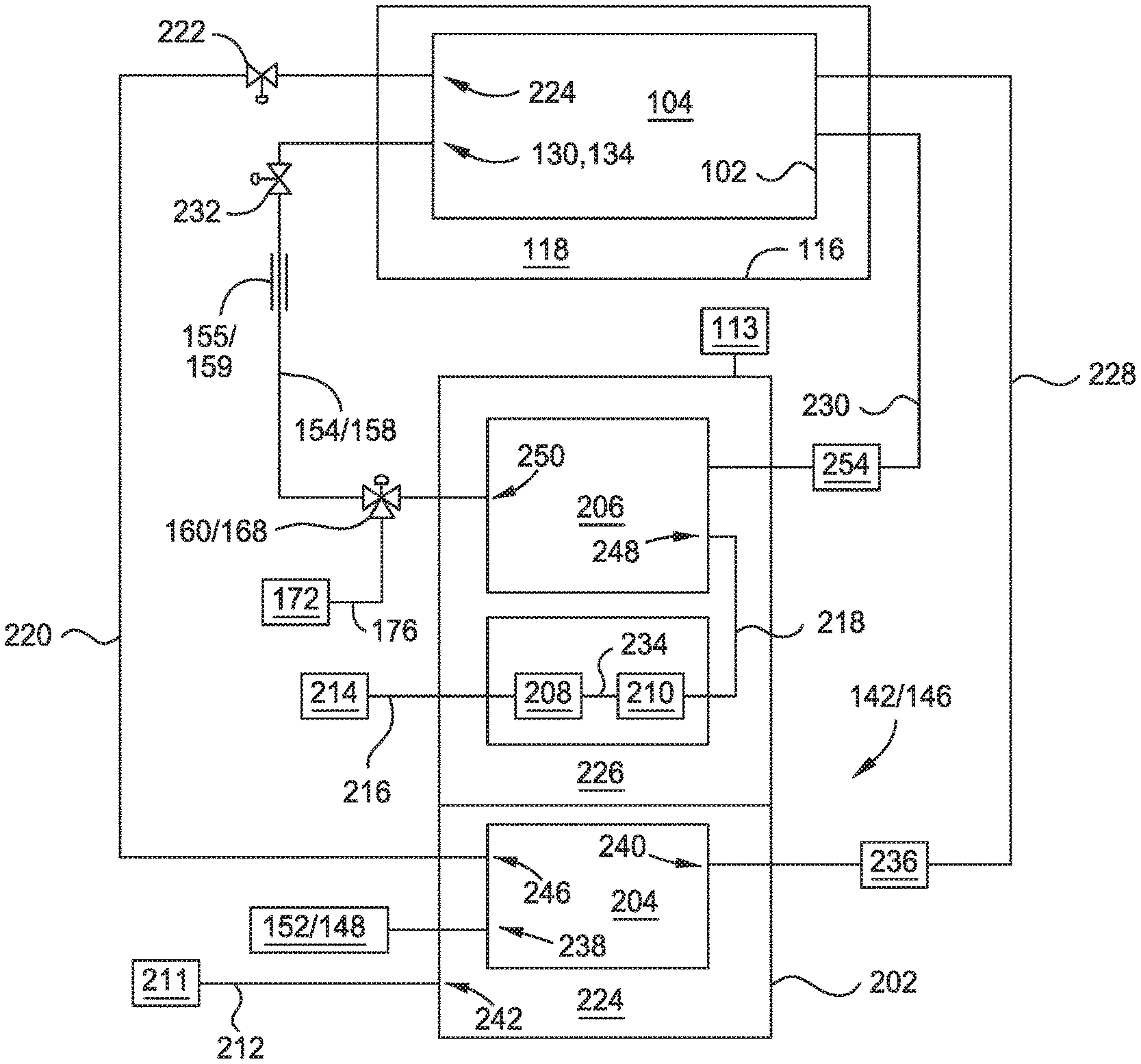
FIG. 2 is a schematic illustration of the fluid delivery module 142/146 according to an embodiment described herein. In one embodiment, the fluid delivery module 142/146 is configured to generate and deliver a low pressure fluid and a high pressure fluid to the second volume 104. The fluid delivery module 142/146 includes a first reservoir 204 and a second reservoir 206. In one embodiment, the first reservoir 204 is a low pressure chemical delivery apparatus which delivers one or more liquid precursors to the second volume 104. In one embodiment, the first reservoir 204 maintains one or more precursors at a sub-atmospheric pressure prior to delivery of the precursors to the second volume 104. The second reservoir 206 is configured to maintain pressurization of a pressurized fluid when the pressurized fluid is delivered to the second reservoir 206.
In one embodiment, the first reservoir 204 and the second reservoir 206 are fabricated from similar materials. For example, the first reservoir 204 and the second reservoir 206 are fabricated from a nickel containing steel alloy. In one embodiment, the first reservoir 204 and the second reservoir 206 are fabricated from a nickel containing steel alloy comprising molybdenum. In another embodiment, the first reservoir 204 and the second reservoir 206 are fabricate from a nickel containing steel alloy comprising chromium. In another embodiment, both of the first reservoir 204 and the second reservoir 206 are fabricated from a stainless steel containing material. In another embodiment, the materials selected for the first reservoir 204 and the second reservoir 206 are different. For example, the first reservoir 204 is fabricated from an aluminum material, a stainless steel material, or alloys thereof and the second reservoir 206 is fabricated from one of the aforementioned nickel containing steel alloys.
The material selected for the second reservoir 206 is highly corrosion resistant to the precursors which are maintained therein at an elevated pressure. One example of precursors which are maintained at elevated (supra-atmospheric) pressure is ammonia. It is also contemplated that various other precursor materials may be utilized in accordance with the embodiments described herein. The materials selected for the first reservoir 204 and the second reservoir 206 are also contemplated to provide sufficient mechanical integrity to enable generation and maintenance of elevated or reduced pressures therein. The first reservoir 204 is operable at temperatures less than about 300.degree. C., for example, less than about 200.degree. C. The second reservoir 206 is operable at temperatures greater than about 250.degree. C., such as temperatures up to about 450.degree. C.
The fluid delivery module 142/146 includes a containment structure 202. In one embodiment, the first reservoir 204 and the second reservoir 206 are disposed within the containment structure 202 in a single volume. In another embodiment, the containment structure 202 is divided to form separate regions therein, for example, a first region 224 and a second region 226. In one embodiment, the first reservoir 204 is disposed in the first region 224 and the second reservoir 206 is disposed in the second region 226. It is contemplated that the regions 224, 226 may either be in fluid communication with one another or may be fluidly isolated from one another, depending upon the containment characteristics desired.
A purge gas source 211 is coupled to a conduit 212 which extends between the purge gas source 211 to a port 242 formed in the containment structure 202. The port 242 is formed in the containment structure 202 adjacent to the first region 224. In one embodiment, the purge gas source 211 is operable to deliver a purge gas, such an N.sub.2 or a noble gas, to the first region 224. In one embodiment, the first region 224 and the second region 226 are in fluid communication with one another and the purge gas source 211 is operable to deliver a purge gas to both the first region 224 and the second region 226. In another embodiment, the purge gas source 211 is in fluid communication with the first reservoir 204. The conduit 212 may be coupled directly or indirectly to the port 242 to enable fluid communication between the purge gas source 211 and the first reservoir 204. In this embodiment, the purge gas source 211 is operable to deliver an inert gas to the first reservoir 204 to purge the first reservoir 204 and remove effluent therefrom. Purge gas from the first reservoir 204 may also be utilized to flush conduit 220 which are coupled to and in fluid communication with the first reservoir 204.
The exhaust 113 is in fluid communication with the second region 226 of the containment structure 202. In one embodiment, fluids existing in the second region 226 outside of the second reservoir 206 are exhausted from the second region 226 to the exhaust 113. In embodiments where the first region 224 and the second region 226 are in fluid communication with one another, fluids from both the first region 224 and the second region 226 are capable of being removed from the regions 224, 226 by the exhaust 113.
The fluid sources 148, 152 are coupled to and in fluid communication with a port 238 formed in the first reservoir 204. In one embodiment, the fluid sources 148, 152 are operable to deliver one or more fluids to the first reservoir 204. In one embodiment, the fluid sources 148, 152 are operable to deliver a liquid precursor to the first reservoir 204. In another embodiment, the fluid sources 148, 152, are operable to deliver a gaseous precursor to the first reservoir 204. In one embodiment, the fluid sources 148, 152 deliver a hafnium containing material, a titanium containing material, or a combination thereof to the first reservoir 204. In one embodiment, the materials delivered from the first reservoir 204 to the second volume 104 are configured to coat surfaces of the second chamber 102.
The first reservoir 204 has a port 240 formed therein which is coupled to a conduit 228. The conduit 228 extends to the second volume 104 and a flow rate controller 236 is disposed inline with the conduit 228. The flow rate controller 236 is operable to control a flow rate of fluid exiting the port 240 and flowing through the conduit 228 to the second volume 104. A port 246 is also formed in the first reservoir 204. A conduit 220 is coupled to the port 246. The conduit 220 extends from the port 246 to the second volume 104. A valve 222 is disposed on the conduit 220 which is operable to enable fluid communication between the first reservoir 204 and the second volume 104.
In one embodiment, both of the conduits 220, 228 are in fluid communication between the first reservoir 204 and the second volume 104. In one embodiment, the conduits 220, 228 enter the second volume 104 opposite one another. In another embodiment, one or both of the conduits 220, 228 are coupled to a showerhead (not illustrated) disposed in the second volume 104 and the showerhead distributes fluid delivered from the first reservoir 204 throughout the second volume 104.
A first gas pump 208 and a second gas pump 210 are disposed in the second region 226. The first gas pump 208 and the second gas pump 210 are operable to generate a staged pressure increase of a gas to be maintained in the second reservoir 206. In one embodiment, the first gas pump 208 and the second gas pump 210 are positioned in series to decrease a ramp time associated with pressurization of a fluid (i.e. gas) to be delivered to the second reservoir 206. Alternatively, the first gas pump 208 and the second gas pump 210 are positioned in parallel and each deliver a pressurized fluid to the conduit 218 which is in fluid communication with the second reservoir 206. In one embodiment, the first gas pump 208 and the second gas pump 210 are pneumatic pumps. In another embodiment, the first gas pump 208 and the second gas pump 210 are hydraulic pumps.
A gas source 214 is in fluid communication with the first gas pump 208 via a conduit 216. In one embodiment, the gas source 214 is a hydrogen source. In another embodiment, the gas source 214 is an ammonia source. In operation, gas is delivered at approximately atmospheric pressure from the gas source 214 to the first gas pump 208. The first gas pump 208 increases a pressure of the gas and delivers the pressurized gas through a conduit 234 which is in fluid communication with the second gas pump 210. The second gas pump 210 further increases the pressure of the gas and delivers the further pressurized gas to the second reservoir through the conduit 218 which is in fluid communication with the second reservoir 206 via a port 248 formed in the second reservoir 206. In one embodiment, the first gas pump 208 and the second gas pump 210 are operable to generate gas pressures of up to about 40,000 psi.
In one embodiment, the gas pumps 208, 210 and the second reservoir 206 are formed from the same material. In one embodiment, the material selected for the gas pumps 208, 210 and the second reservoir 206 is a stainless steel material, a nickel containing stainless steel material, a nickel molybdenum containing stainless steel material, a nickel chromium stainless steel material, and combinations and mixtures thereof. The materials selected for the gas pumps 208, 210 and the second reservoir 206 are selected to be substantially inert to the pressurized gases flowing therethrough. As such, corrosion of the gas pumps 208, 210 and the second reservoir 206 is reduced which lengthens the useful life of the apparatus and improved the operation thereof by reducing the probability of a catastrophic failure under the elevated pressures generated therein.
A port 250 is also formed in the second reservoir 206. The port 250 is in fluid communication with the conduit 154, 158. A valve 232 is disposed on the conduit 154, 158 which selectively enables fluid communication between the second reservoir 206 and the second volume 104.
In operation, a pressurized fluid is generated by the pumps 208, 210 and delivered to the second reservoir 206. The second reservoir 206 functions as a pressure vessel to hold the fluid in a pressurized state until the fluid is delivered to the second volume 104. A controller 254 is in fluid communication between the second reservoir 206 and the second volume 104 via a conduit 230. The controller 254 measures a pressure within the second volume 104 and determines whether more or less fluid is needed in the second volume 104 to maintain a set pressure point or range of pressure. The controller 254 is also in communication with one or both of the valves 160, 168 and the valve 232 to facilitate fluid delivery to the second volume 104. Thus, the controller 254 provides for closed loop control to enable maintenance of a desired process pressure within the second volume 104.
In summation, apparatus for high pressure processing are described herein. Fluid delivery modules enable generation of fluids at high pressure and facilitate delivery of such fluids to a volume of a process chamber. In one embodiment, the fluid delivery module for generation and delivery of a pressurized fluid includes a second reservoir fabricated from corrosion resistant materials. A first reservoir receives a fluid precursor and delivers the fluid precursor to the second volume. The first reservoir and the second reservoir are in fluid communication with the second volume to coat the chamber and perform high pressure processing in the process chamber, respectively. Various containment apparatus and pressure relief architectures are also described herein to enable safe and efficient operation of apparatus during high pressure processing.
While the foregoing is directed to embodiments of the present disclosure, other and further embodiments of the disclosure may be devised without departing from the basic scope thereof, and the scope thereof is determined by the claims that follow.
* * * * *
D00000
D00001
D00002
XML
uspto.report is an independent third-party trademark research tool that is not affiliated, endorsed, or sponsored by the United States Patent and Trademark Office (USPTO) or any other governmental organization. The information provided by uspto.report is based on publicly available data at the time of writing and is intended for informational purposes only.
While we strive to provide accurate and up-to-date information, we do not guarantee the accuracy, completeness, reliability, or suitability of the information displayed on this site. The use of this site is at your own risk. Any reliance you place on such information is therefore strictly at your own risk.
All official trademark data, including owner information, should be verified by visiting the official USPTO website at www.uspto.gov. This site is not intended to replace professional legal advice and should not be used as a substitute for consulting with a legal professional who is knowledgeable about trademark law.