Coaxial cable connector
Burris , et al. Feb
U.S. patent number 10,211,547 [Application Number 14/844,592] was granted by the patent office on 2019-02-19 for coaxial cable connector. This patent grant is currently assigned to Corning Optical Communications RF LLC. The grantee listed for this patent is Corning Optical Communications RF LLC. Invention is credited to Donald Andrew Burris, Jimmy Valentin Falster, Michael Ole Matzen, Michael Meister, Thomas Dewey Miller.


View All Diagrams
| United States Patent | 10,211,547 |
| Burris , et al. | February 19, 2019 |
| **Please see images for: ( Certificate of Correction ) ** |
Coaxial cable connector
Abstract
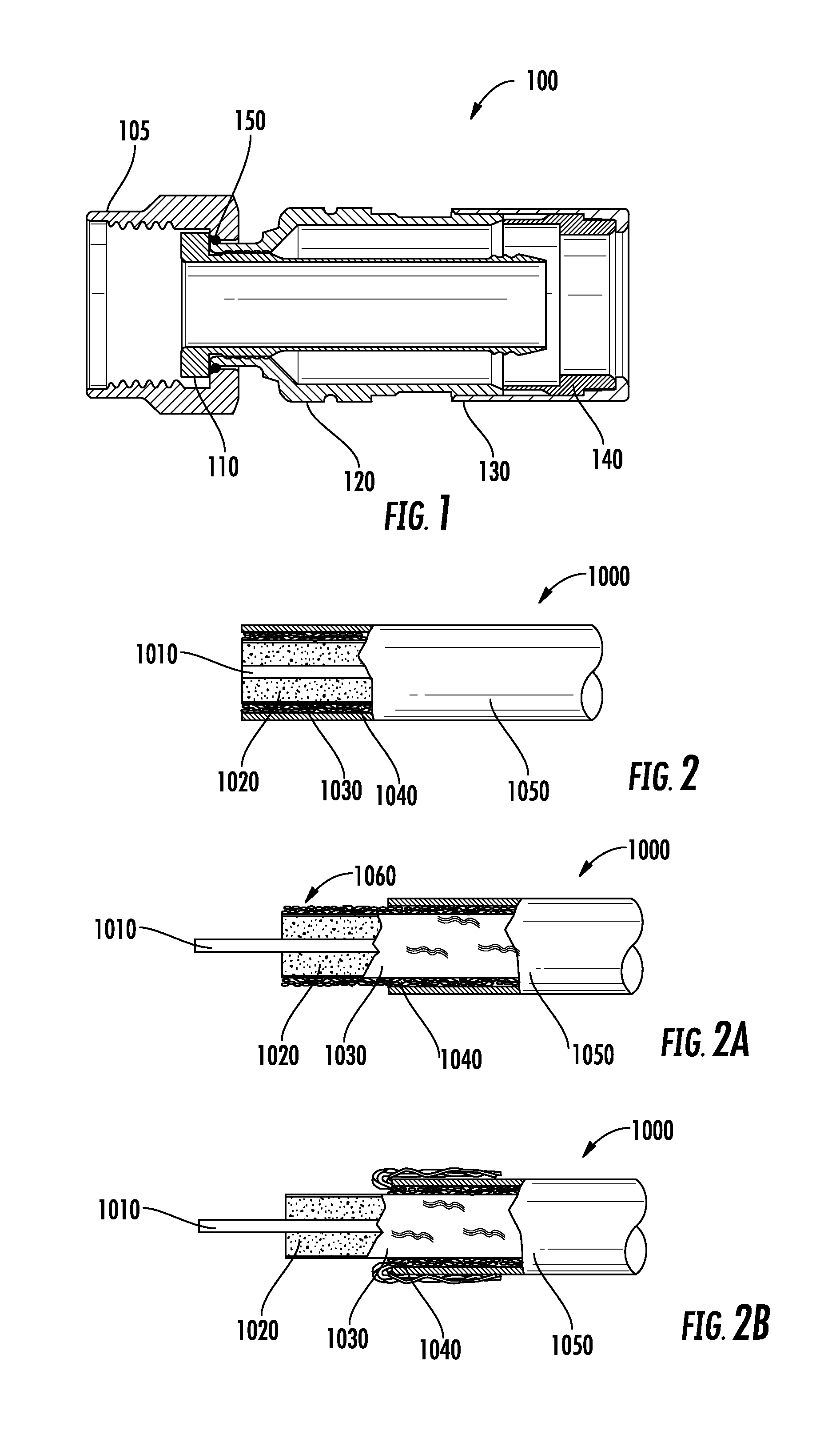
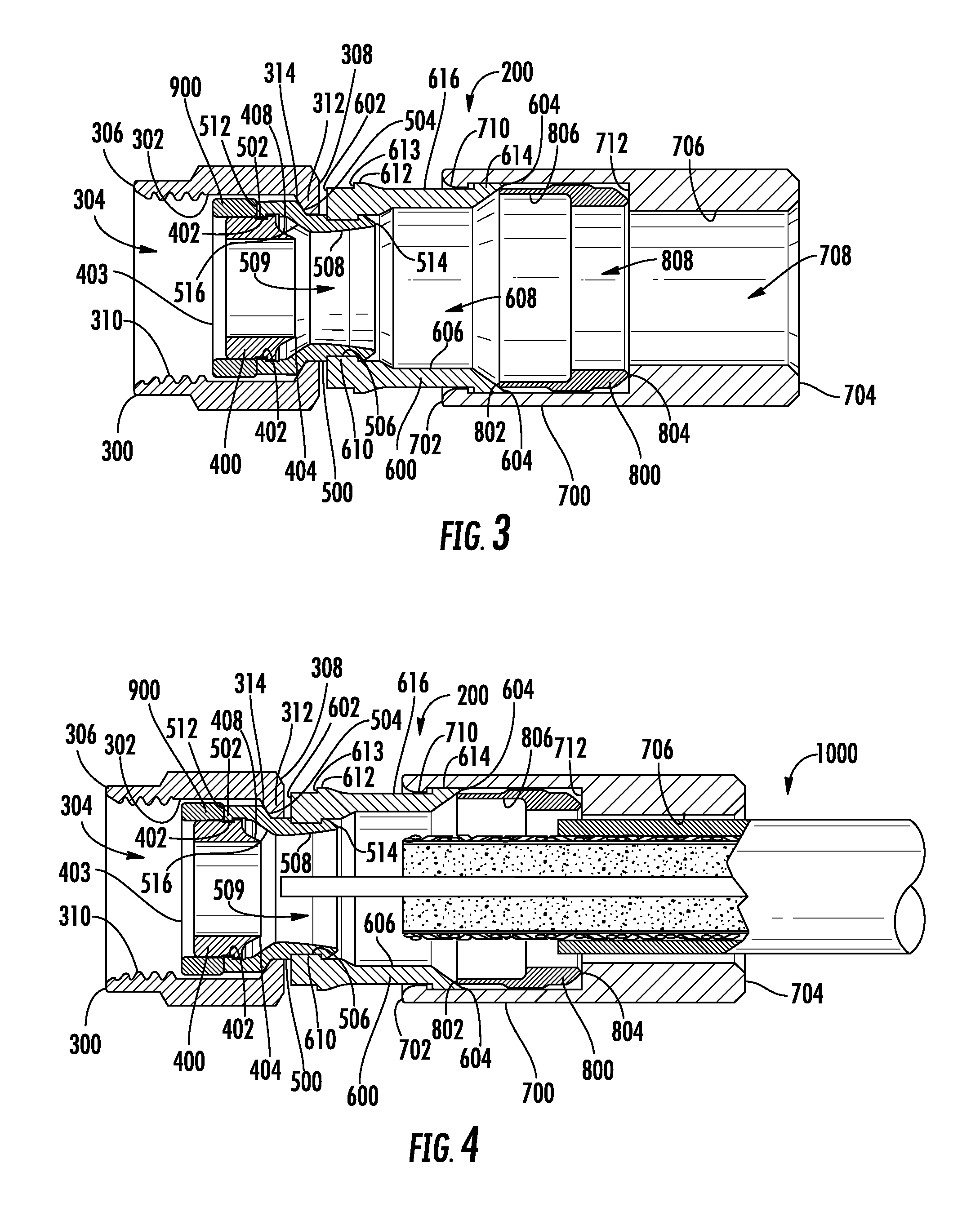
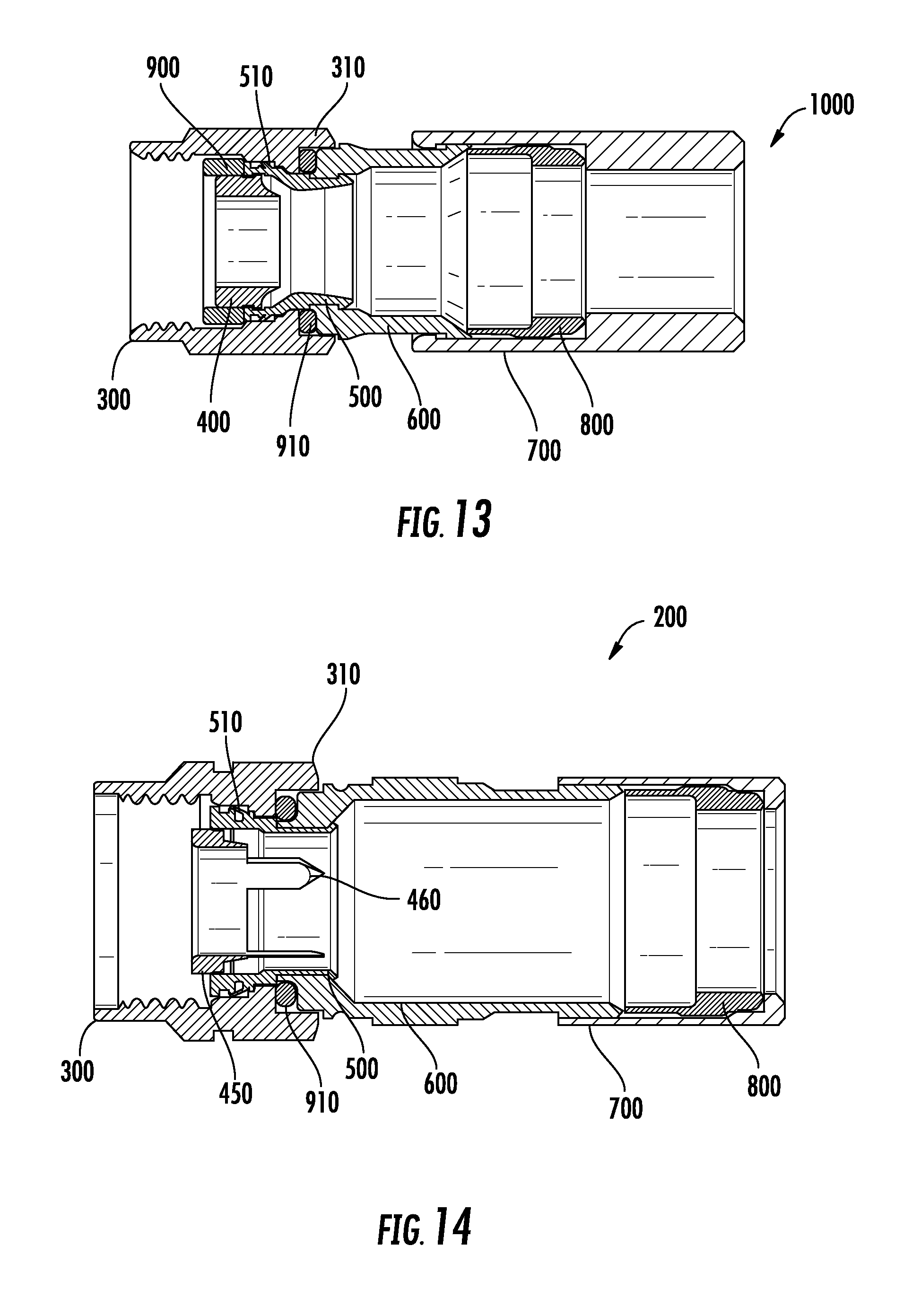
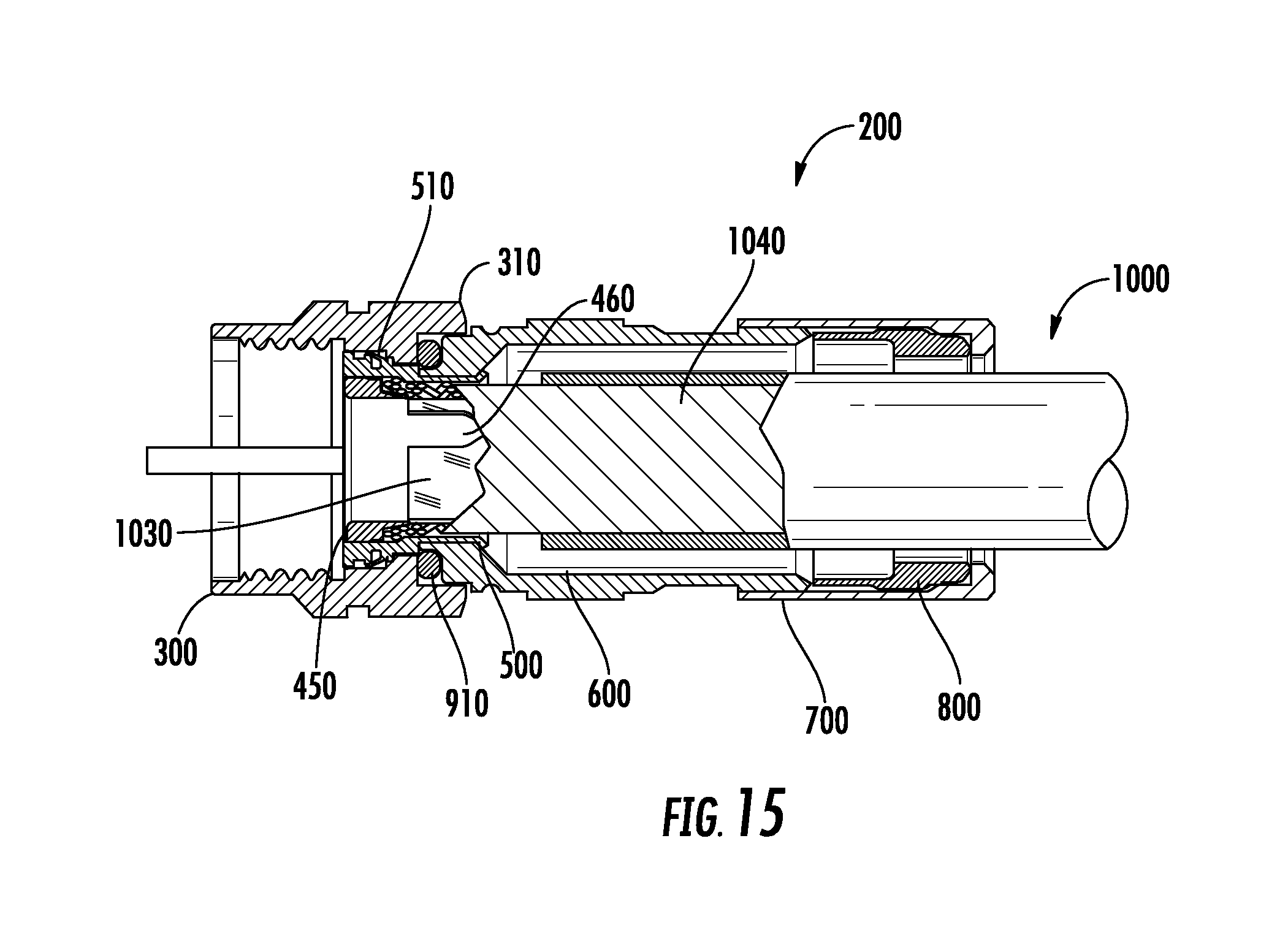
Connectors and methods for attaching connectors to one or more cables and/or conduits are disclosed. The disclosed connectors and methods may secure an outer surface of the cable (e.g., an outer jacket of a cable) or conduit. A connector, for example, may include a coupler comprising an inner surface defining an coupler inner bore; a retainer comprising an inner surface defining a retainer inner bore configured to receive the inner conductor and insulator layer of a coaxial cable and an outer angled rear facing surface configured to extend between the insulator layer and the outer conductor layer of the coaxial cable, the retainer disposed within the inner bore of the coupler; a hub engaged to the retainer and disposed at least partially within the inner bore of the coupler, the hub rotatably engaged with the coupler, the hub further comprising an outer angled forward facing surface at least partially opposing the outer angled rear facing surface of the retainer, wherein the outer angled rear facing surface of the retainer and the outer angled forward facing surface of the hub are configured to secure the outer conductor layer between the outer angled rear facing surface of the retainer and the outer angled forward facing surface of the hub.
| Inventors: | Burris; Donald Andrew (Peoria, AZ), Falster; Jimmy Valentin (Vordingborg, DK), Matzen; Michael Ole (Vordingborg, DK), Meister; Michael (Langebaek, DK), Miller; Thomas Dewey (Peoria, AZ) | ||||||||||
|---|---|---|---|---|---|---|---|---|---|---|---|
| Applicant: |
|
||||||||||
| Assignee: | Corning Optical Communications RF
LLC (Glendale, AZ) |
||||||||||
| Family ID: | 56852177 | ||||||||||
| Appl. No.: | 14/844,592 | ||||||||||
| Filed: | September 3, 2015 |
Prior Publication Data
| Document Identifier | Publication Date | |
|---|---|---|
| US 20170069982 A1 | Mar 9, 2017 | |
| Current U.S. Class: | 1/1 |
| Current CPC Class: | H01R 9/0524 (20130101); H01R 9/05 (20130101); H01R 43/16 (20130101) |
| Current International Class: | H01R 9/05 (20060101); H01R 43/16 (20060101) |
| Field of Search: | ;439/584,585,578 |
References Cited [Referenced By]
U.S. Patent Documents
| 331169 | November 1885 | Thomas |
| 346958 | August 1886 | Stone |
| 459951 | September 1891 | Warner |
| 589216 | August 1897 | McKee |
| 1371742 | March 1921 | Dringman |
| 1488175 | March 1924 | Strandell |
| 1667485 | April 1928 | MacDonald |
| 1766869 | June 1930 | Austin |
| 1801999 | April 1931 | Bowman |
| 1885761 | November 1932 | Peirce, Jr. |
| 1959302 | May 1934 | Paige |
| 2013526 | September 1935 | Schmitt |
| 2059920 | November 1936 | Weatherhead, Jr. |
| 2102495 | December 1937 | England |
| 2258528 | October 1941 | Wurzburger |
| 2258737 | October 1941 | Browne |
| 2325549 | July 1943 | Ryzowitz |
| 2480963 | September 1949 | Quinn |
| 2544654 | March 1951 | Brown |
| 2549647 | April 1951 | Turenne |
| 2694187 | November 1954 | Nash |
| 2705652 | April 1955 | Kaiser |
| 2743505 | May 1956 | Hill |
| 2754487 | July 1956 | Carr et al. |
| 2755331 | July 1956 | Melcher |
| 2757351 | July 1956 | Klostermann |
| 2762025 | September 1956 | Melcher |
| 2785384 | March 1957 | Wickesser |
| 2805399 | September 1957 | Leeper |
| 2816949 | December 1957 | Curtiss |
| 2870420 | January 1959 | Malek |
| 2878039 | March 1959 | Hoegee et al. |
| 2881406 | April 1959 | Arson |
| 2963536 | December 1960 | Kokalas |
| 3001169 | September 1961 | Blonder |
| 3015794 | January 1962 | Kishbaugh |
| 3051925 | August 1962 | Felts |
| 3091748 | May 1963 | Takes et al. |
| 3094364 | June 1963 | Lingg |
| 3103548 | September 1963 | Concelman |
| 3106548 | October 1963 | Lavalou |
| 3140106 | July 1964 | Thomas et al. |
| 3161451 | December 1964 | Neidecker |
| 3184706 | May 1965 | Atkins |
| 3193309 | July 1965 | Morris |
| 3194292 | July 1965 | Borowsky |
| 3196382 | July 1965 | Morello, Jr. |
| 3206540 | September 1965 | Cohen |
| 3245027 | April 1966 | Ziegler, Jr. |
| 3275913 | September 1966 | Blanchard et al. |
| 3278890 | October 1966 | Cooney |
| 3281756 | October 1966 | O'Keefe et al. |
| 3281757 | October 1966 | Bonhomme |
| 3290069 | December 1966 | Davis |
| 3292136 | December 1966 | Somerset |
| 3320575 | May 1967 | Brown et al. |
| 3321732 | May 1967 | Forney, Jr. |
| 3336563 | August 1967 | Hyslop |
| 3348186 | October 1967 | Rosen |
| 3350667 | October 1967 | Shreve |
| 3350677 | October 1967 | Daum |
| 3355698 | November 1967 | Keller |
| 3372364 | March 1968 | O'Keefe et al. |
| 3373243 | March 1968 | Janowiak et al. |
| 3390374 | June 1968 | Forney, Jr. |
| 3406373 | October 1968 | Forney, Jr. |
| 3430184 | February 1969 | Acord |
| 3448430 | June 1969 | Kelly |
| 3453376 | July 1969 | Ziegler, Jr. et al. |
| 3465281 | September 1969 | Florer |
| 3475545 | October 1969 | Stark et al. |
| 3494400 | February 1970 | McCoy et al. |
| 3498647 | March 1970 | Schroder |
| 3499671 | March 1970 | Osborne |
| 3501737 | March 1970 | Harris et al. |
| 3517373 | June 1970 | Jamon |
| 3526871 | September 1970 | Hobart |
| 3533051 | October 1970 | Ziegler, Jr. |
| 3537065 | October 1970 | Winston |
| 3544705 | December 1970 | Winston |
| 3551882 | December 1970 | O'Keefe |
| 3564487 | February 1971 | Upstone et al. |
| 3587033 | June 1971 | Brorein et al. |
| 3596933 | August 1971 | Luckenbill |
| 3601776 | August 1971 | Curl |
| 3603912 | September 1971 | Kelly |
| 3614711 | October 1971 | Anderson et al. |
| 3622952 | November 1971 | Hilbert |
| 3629792 | December 1971 | Dorrell |
| 3633150 | January 1972 | Schwartz |
| 3646502 | February 1972 | Hutter et al. |
| 3663926 | May 1972 | Brandt |
| 3665371 | May 1972 | Cripps |
| 3668612 | June 1972 | Nepovim |
| 3669472 | June 1972 | Nadsady |
| 3671922 | June 1972 | Zerlin et al. |
| 3671926 | June 1972 | Nepovim |
| 3678444 | July 1972 | Stevens et al. |
| 3678445 | July 1972 | Brancaloene |
| 3680034 | July 1972 | Chow et al. |
| 3681739 | August 1972 | Kornick |
| 3683320 | August 1972 | Woods et al. |
| 3686623 | August 1972 | Nijman |
| 3694792 | September 1972 | Wallo |
| 3694793 | September 1972 | Concelman |
| 3697930 | October 1972 | Shirey |
| 3706958 | December 1972 | Blanchenot |
| 3708186 | January 1973 | Takagi et al. |
| 3710005 | January 1973 | French |
| 3739076 | June 1973 | Schwartz |
| 3744007 | July 1973 | Horak |
| 3744011 | July 1973 | Blanchenot |
| 3761870 | September 1973 | Drezin et al. |
| 3778535 | December 1973 | Forney, Jr. |
| 3781762 | December 1973 | Quackenbush |
| 3781898 | December 1973 | Holloway |
| 3783178 | January 1974 | Philibert et al. |
| 3787796 | January 1974 | Barr |
| 3793610 | February 1974 | Brishka |
| 3798589 | March 1974 | Deardurff |
| 3808580 | April 1974 | Johnson |
| 3810076 | May 1974 | Hutter |
| 3824026 | July 1974 | Gaskins |
| 3835443 | September 1974 | Arnold et al. |
| 3836700 | September 1974 | Niemeyer |
| 3845453 | October 1974 | Hemmer |
| 3846738 | November 1974 | Nepovim |
| 3847463 | November 1974 | Hayward et al. |
| 3854003 | December 1974 | Duret |
| 3854789 | December 1974 | Kaplan |
| 3858156 | December 1974 | Zarro |
| 3879102 | April 1975 | Horak |
| 3886301 | May 1975 | Cronin et al. |
| 3907335 | September 1975 | Burge et al. |
| 3907399 | September 1975 | Spinner |
| 3910673 | October 1975 | Stokes |
| 3915539 | October 1975 | Collins |
| 3936132 | February 1976 | Hutter |
| 3937547 | February 1976 | Lee-Kemp |
| 3953097 | April 1976 | Graham |
| 3960428 | June 1976 | Naus et al. |
| 3963320 | June 1976 | Spinner |
| 3963321 | June 1976 | Burger et al. |
| 3970355 | July 1976 | Pitschi |
| 3972013 | July 1976 | Shapiro |
| 3976352 | August 1976 | Spinner |
| 3980805 | September 1976 | Lipari |
| 3985418 | October 1976 | Spinner |
| 3986736 | October 1976 | Takagi et al. |
| 4012105 | March 1977 | Biddle |
| 4017139 | April 1977 | Nelson |
| 4022966 | May 1977 | Gajajiva |
| 4030742 | June 1977 | Eidelberg et al. |
| 4030798 | June 1977 | Paoli |
| 4032177 | June 1977 | Anderson |
| 4045706 | August 1977 | Daffner et al. |
| 4046451 | September 1977 | Juds et al. |
| 4053200 | October 1977 | Pugner |
| 4056043 | November 1977 | Sriramamurty et al. |
| 4059330 | November 1977 | Shirey |
| 4079343 | March 1978 | Nijman |
| 4082404 | April 1978 | Flatt |
| 4090028 | May 1978 | Vontobel |
| 4093335 | June 1978 | Schwartz et al. |
| 4100943 | July 1978 | Terada et al. |
| 4106839 | August 1978 | Cooper |
| 4109126 | August 1978 | Halbeck |
| 4118097 | October 1978 | Budnick |
| 4125308 | November 1978 | Schilling |
| 4126372 | November 1978 | Hashimoto et al. |
| 4131332 | December 1978 | Hogendobler et al. |
| 4136897 | January 1979 | Haluch |
| 4150250 | April 1979 | Lundeberg |
| 4153320 | May 1979 | Townshend |
| 4156554 | May 1979 | Aujla |
| 4165911 | August 1979 | Laudig |
| 4168921 | September 1979 | Blanchard |
| 4169646 | October 1979 | Stape et al. |
| 4173385 | November 1979 | Fenn et al. |
| 4174875 | November 1979 | Wilson et al. |
| 4187481 | February 1980 | Bourtos |
| 4193655 | March 1980 | Herrmann, Jr. |
| 4194338 | March 1980 | Trafton |
| 4197628 | April 1980 | Conti et al. |
| 4206963 | June 1980 | English et al. |
| 4212487 | July 1980 | Jones et al. |
| 4225162 | September 1980 | Dola |
| 4227765 | October 1980 | Neumann et al. |
| 4229714 | October 1980 | Yu |
| 4239318 | December 1980 | Schwartz |
| 4250348 | February 1981 | Kitagawa |
| 4260212 | April 1981 | Ritchie |
| 4273405 | June 1981 | Law |
| 4280749 | July 1981 | Hemmer |
| 4285564 | August 1981 | Spinner |
| 4290663 | September 1981 | Fowler et al. |
| 4296986 | October 1981 | Herrmann, Jr. |
| 4307926 | December 1981 | Smith |
| 4309050 | January 1982 | Legris |
| 4310211 | January 1982 | Bunnell et al. |
| 4322121 | March 1982 | Riches et al. |
| 4326768 | April 1982 | Punako |
| 4326769 | April 1982 | Dorsey et al. |
| 4334730 | June 1982 | Colwell et al. |
| 4339166 | July 1982 | Dayton |
| 4345375 | August 1982 | Hayward |
| 4346958 | August 1982 | Blanchard |
| 4354721 | October 1982 | Luzzi |
| 4358174 | November 1982 | Dreyer |
| 4373767 | February 1983 | Cairns |
| 4389081 | June 1983 | Gallusser et al. |
| 4400050 | August 1983 | Hayward |
| 4407529 | October 1983 | Holman |
| 4408821 | October 1983 | Forney, Jr. |
| 4408822 | October 1983 | Nikitas |
| 4412717 | November 1983 | Monroe |
| 4421377 | December 1983 | Spinner |
| 4426127 | January 1984 | Kubota |
| 4428639 | January 1984 | Hillis |
| 4444453 | April 1984 | Kirby et al. |
| 4447107 | May 1984 | Major et al. |
| 4452503 | June 1984 | Forney, Jr. |
| 4453200 | June 1984 | Trcka et al. |
| 4456323 | June 1984 | Pitcher et al. |
| 4459881 | July 1984 | Hughes, Jr. |
| 4462653 | July 1984 | Flederbach et al. |
| 4464000 | August 1984 | Werth et al. |
| 4464001 | August 1984 | Collins |
| 4469386 | September 1984 | Ackerman |
| 4470657 | September 1984 | Deacon |
| 4477132 | October 1984 | Moser et al. |
| 4484792 | November 1984 | Tengler et al. |
| 4484796 | November 1984 | Sato et al. |
| 4490576 | December 1984 | Bolante et al. |
| 4491685 | January 1985 | Drew et al. |
| 4506943 | March 1985 | Drogo |
| 4515427 | May 1985 | Smit |
| 4525017 | June 1985 | Schildkraut et al. |
| 4531790 | July 1985 | Selvin |
| 4531805 | July 1985 | Werth |
| 4533191 | August 1985 | Blackwood |
| 4540231 | September 1985 | Forney, Jr. |
| RE31995 | October 1985 | Ball |
| 4545633 | October 1985 | McGeary |
| 4545637 | October 1985 | Bosshard et al. |
| 4553877 | November 1985 | Edvardsen |
| 4575274 | March 1986 | Hayward |
| 4580862 | April 1986 | Johnson |
| 4580865 | April 1986 | Fryberger |
| 4583811 | April 1986 | McMills |
| 4585289 | April 1986 | Bocher |
| 4588246 | May 1986 | Schildkraut et al. |
| 4593964 | June 1986 | Forney, Jr. et al. |
| 4596434 | June 1986 | Saba et al. |
| 4596435 | June 1986 | Bickford |
| 4597621 | July 1986 | Burns |
| 4598959 | July 1986 | Selvin |
| 4598961 | July 1986 | Cohen |
| 4600263 | July 1986 | DeChamp et al. |
| 4613199 | September 1986 | McGeary |
| 4614390 | September 1986 | Baker |
| 4616900 | October 1986 | Cairns |
| 4623205 | November 1986 | Barron |
| 4632487 | December 1986 | Wargula |
| 4634213 | January 1987 | Larsson et al. |
| 4640572 | February 1987 | Conlon |
| 4645281 | February 1987 | Burger |
| 4647135 | March 1987 | Reinhardt |
| 4650228 | March 1987 | McMills et al. |
| 4655159 | April 1987 | McMills |
| 4655534 | April 1987 | Stursa |
| 4660921 | April 1987 | Hauver |
| 4666190 | May 1987 | Yamabe et al. |
| 4666231 | May 1987 | Sheesley et al. |
| 4668043 | May 1987 | Saba et al. |
| 4670574 | June 1987 | Malcolm |
| 4673236 | June 1987 | Musolff et al. |
| 4674809 | June 1987 | Hollyday et al. |
| 4674818 | June 1987 | McMills et al. |
| 4676577 | June 1987 | Szegda |
| 4682832 | July 1987 | Punako et al. |
| 4684201 | August 1987 | Hutter |
| 4688876 | August 1987 | Morelli |
| 4688878 | August 1987 | Cohen et al. |
| 4690482 | September 1987 | Chamberland et al. |
| 4691976 | September 1987 | Cowen |
| 4703987 | November 1987 | Gullusser et al. |
| 4703988 | November 1987 | Raux et al. |
| 4713021 | December 1987 | Kobler |
| 4717355 | January 1988 | Mattis |
| 4720155 | January 1988 | Schildkraut et al. |
| 4728301 | March 1988 | Hemmer et al. |
| 4734050 | March 1988 | Negre et al. |
| 4734666 | March 1988 | Ohya et al. |
| 4737123 | April 1988 | Paler et al. |
| 4738009 | April 1988 | Down et al. |
| 4738628 | April 1988 | Rees |
| 4739009 | April 1988 | Down et al. |
| 4739126 | April 1988 | Gutter et al. |
| 4746305 | May 1988 | Nomura |
| 4747656 | May 1988 | Miyahara et al. |
| 4747786 | May 1988 | Hayashi et al. |
| 4749821 | June 1988 | Linton et al. |
| 4755152 | July 1988 | Elliot et al. |
| 4757274 | July 1988 | Bowers |
| 4757297 | July 1988 | Frawley |
| 4759729 | July 1988 | Kemppainen et al. |
| 4761146 | August 1988 | Sohoel |
| 4772222 | September 1988 | Laudig et al. |
| 4789355 | December 1988 | Lee |
| 4789759 | December 1988 | Jones |
| 4795360 | January 1989 | Newman et al. |
| 4797120 | January 1989 | Ulery |
| 4806116 | February 1989 | Ackerman |
| 4807891 | February 1989 | Neher |
| 4808128 | February 1989 | Werth |
| 4810017 | March 1989 | Knak et al. |
| 4813886 | March 1989 | Roos et al. |
| 4820185 | April 1989 | Moulin |
| 4834675 | May 1989 | Samchisen |
| 4834676 | May 1989 | Tackett |
| 4835342 | May 1989 | Guginsky |
| 4836580 | June 1989 | Farrell |
| 4836801 | June 1989 | Ramirez |
| 4838813 | June 1989 | Pauza et al. |
| 4846731 | July 1989 | Alwine |
| 4854893 | August 1989 | Morris |
| 4857014 | August 1989 | Alf et al. |
| 4867489 | September 1989 | Patel |
| 4867706 | September 1989 | Tang |
| 4869679 | September 1989 | Szegda |
| 4874331 | October 1989 | Iverson |
| 4881912 | November 1989 | Thommen et al. |
| 4892275 | January 1990 | Szegda |
| 4902246 | February 1990 | Samchisen |
| 4906207 | March 1990 | Banning et al. |
| 4915651 | April 1990 | Bout |
| 4921447 | May 1990 | Capp et al. |
| 4923412 | May 1990 | Morris |
| 4925403 | May 1990 | Zorzy |
| 4927385 | May 1990 | Cheng |
| 4929188 | May 1990 | Lionetto et al. |
| 4934960 | June 1990 | Capp et al. |
| 4938718 | July 1990 | Guendel |
| 4941846 | July 1990 | Guimond et al. |
| 4952174 | August 1990 | Sucht et al. |
| 4957456 | September 1990 | Olson et al. |
| 4963105 | October 1990 | Lewis et al. |
| 4964805 | October 1990 | Gabany |
| 4964812 | October 1990 | Siemon et al. |
| 4973265 | November 1990 | Heeren |
| 4976632 | December 1990 | Riches |
| 4979911 | December 1990 | Spencer |
| 4990104 | February 1991 | Schieferly |
| 4990105 | February 1991 | Karlovich |
| 4990106 | February 1991 | Szegda |
| 4992061 | February 1991 | Brush, Jr. et al. |
| 5002503 | March 1991 | Campbell et al. |
| 5007861 | April 1991 | Stirling |
| 5011422 | April 1991 | Yeh |
| 5011432 | April 1991 | Sucht et al. |
| 5018822 | May 1991 | Freismuth et al. |
| 5021010 | June 1991 | Wright |
| 5024606 | June 1991 | Ming-Hwa |
| 5030126 | July 1991 | Hanlon |
| 5037328 | August 1991 | Karlovich |
| 5046964 | September 1991 | Welsh et al. |
| 5052947 | October 1991 | Brodie et al. |
| 5055060 | October 1991 | Down et al. |
| 5059139 | October 1991 | Spinner |
| 5059747 | October 1991 | Bawa et al. |
| 5062804 | November 1991 | Jamet et al. |
| 5066248 | November 1991 | Gaver, Jr. et al. |
| 5067912 | November 1991 | Bickford et al. |
| 5073129 | December 1991 | Szegda |
| 5074809 | December 1991 | Rousseau |
| 5080600 | January 1992 | Baker et al. |
| 5083943 | January 1992 | Tarrant |
| 5088937 | February 1992 | Gabany |
| 5120260 | June 1992 | Jackson |
| 5127853 | July 1992 | McMills et al. |
| 5131862 | July 1992 | Gershfeld |
| 5137470 | August 1992 | Doles |
| 5137471 | August 1992 | Verespej et al. |
| 5139440 | August 1992 | Volk et al. |
| 5141448 | August 1992 | Mattingly et al. |
| 5141451 | August 1992 | Down |
| 5149274 | September 1992 | Gallusser et al. |
| 5150924 | September 1992 | Yokomatsu et al. |
| 5154636 | October 1992 | Vaccaro et al. |
| 5161993 | November 1992 | Leibfried, Jr. |
| 5166477 | November 1992 | Perin, Jr. et al. |
| 5167545 | December 1992 | O'Brien et al. |
| 5169323 | December 1992 | Kawai et al. |
| 5176530 | January 1993 | Reylek |
| 5176533 | January 1993 | Sakurai et al. |
| 5181161 | January 1993 | Hirose et al. |
| 5183417 | February 1993 | Bools |
| 5185655 | February 1993 | Glenday et al. |
| 5186501 | February 1993 | Mano |
| 5186655 | February 1993 | Glenday et al. |
| 5195904 | March 1993 | Cyvoct |
| 5195905 | March 1993 | Pesci |
| 5195906 | March 1993 | Szegda |
| 5205547 | April 1993 | Mattingly |
| 5205761 | April 1993 | Nilsson |
| D335487 | May 1993 | Volk et al. |
| 5207602 | May 1993 | McMills et al. |
| 5215477 | June 1993 | Weber et al. |
| 5217391 | June 1993 | Fisher, Jr. |
| 5217392 | June 1993 | Hosler, Sr. |
| 5217393 | June 1993 | Del Negro et al. |
| 5221216 | June 1993 | Gabany et al. |
| 5227587 | July 1993 | Paterek |
| 5247424 | September 1993 | Harris et al. |
| 5263880 | November 1993 | Schwarz et al. |
| 5269701 | December 1993 | Leibfried, Jr. |
| 5281762 | January 1994 | Long et al. |
| 5283417 | February 1994 | Misawa et al. |
| 5283853 | February 1994 | Szegda |
| 5284449 | February 1994 | Vaccaro |
| 5294864 | March 1994 | Do |
| 5295864 | March 1994 | Birch et al. |
| 5316348 | May 1994 | Franklin |
| 5316494 | May 1994 | Flanagan et al. |
| 5318459 | June 1994 | Sheilds |
| 5321205 | June 1994 | Bawa et al. |
| 5334032 | August 1994 | Myers et al. |
| 5334051 | August 1994 | Devine et al. |
| 5338225 | August 1994 | Jacobsen et al. |
| 5342218 | August 1994 | McMills et al. |
| 5352134 | October 1994 | Jacobsen et al. |
| 5354217 | October 1994 | Gabel et al. |
| 5362250 | November 1994 | McMills et al. |
| 5362251 | November 1994 | Bielak |
| 5366260 | November 1994 | Wartluft |
| 5371819 | December 1994 | Szegda |
| 5371821 | December 1994 | Szegda |
| 5371827 | December 1994 | Szegda |
| 5380211 | January 1995 | Kawagauchi et al. |
| 5389005 | February 1995 | Kodama |
| 5393244 | February 1995 | Szegda |
| 5397252 | March 1995 | Wang |
| 5413504 | May 1995 | Kloecker et al. |
| 5431583 | July 1995 | Szegda |
| 5435745 | July 1995 | Booth |
| 5435751 | July 1995 | Papenheim et al. |
| 5435760 | July 1995 | Miklos |
| 5439386 | August 1995 | Ellis et al. |
| 5444810 | August 1995 | Szegda |
| 5455548 | October 1995 | Grandchamp et al. |
| 5456611 | October 1995 | Henry et al. |
| 5456614 | October 1995 | Szegda |
| 5466173 | November 1995 | Down |
| 5470257 | November 1995 | Szegda |
| 5474478 | December 1995 | Ballog |
| 5475921 | December 1995 | Johnston |
| 5488268 | January 1996 | Bauer et al. |
| 5490033 | February 1996 | Cronin |
| 5490801 | February 1996 | Fisher, Jr. et al. |
| 5494454 | February 1996 | Johnsen |
| 5499934 | March 1996 | Jacobsen et al. |
| 5501616 | March 1996 | Holliday |
| 5511305 | April 1996 | Garner |
| 5516303 | May 1996 | Yohn et al. |
| 5525076 | June 1996 | Down |
| 5542861 | August 1996 | Anhalt et al. |
| 5548088 | August 1996 | Gray et al. |
| 5550521 | August 1996 | Bernaud et al. |
| 5564938 | October 1996 | Shenkal et al. |
| 5566173 | October 1996 | Steinbrecher |
| 5571028 | November 1996 | Szegda |
| 5571029 | November 1996 | Poissant et al. |
| 5586910 | December 1996 | Del Negro et al. |
| 5595499 | January 1997 | Zander et al. |
| 5598132 | January 1997 | Stabile |
| 5607320 | March 1997 | Wright |
| 5607325 | March 1997 | Toma |
| 5609501 | March 1997 | McMills et al. |
| 5620339 | April 1997 | Gray et al. |
| 5632637 | May 1997 | Diener |
| 5632651 | May 1997 | Szegda |
| 5644104 | July 1997 | Porter et al. |
| 5649723 | July 1997 | Larsson |
| 5651698 | July 1997 | Locati et al. |
| 5651699 | July 1997 | Holliday |
| 5653605 | August 1997 | Woehl et al. |
| 5667405 | September 1997 | Holliday |
| 5681172 | October 1997 | Moldenhauer |
| 5683263 | November 1997 | Hsu |
| 5702263 | December 1997 | Baumann et al. |
| 5722856 | March 1998 | Fuchs et al. |
| 5735704 | April 1998 | Anthony |
| 5743131 | April 1998 | Holliday et al. |
| 5746617 | May 1998 | Porter, Jr. et al. |
| 5746619 | May 1998 | Harting et al. |
| 5759618 | June 1998 | Taylor |
| 5761053 | June 1998 | King et al. |
| 5769622 | June 1998 | Stabile et al. |
| 5769652 | June 1998 | Wider |
| 5769662 | June 1998 | Stabile et al. |
| 5774344 | June 1998 | Casebolt |
| 5775927 | July 1998 | Wider |
| 5788289 | August 1998 | Cronley |
| 5791698 | August 1998 | Wartluft et al. |
| 5797633 | August 1998 | Katzer et al. |
| 5817978 | October 1998 | Hermant et al. |
| 5863220 | January 1999 | Holliday |
| 5874603 | February 1999 | Arkles |
| 5877452 | March 1999 | McConnell |
| 5879191 | March 1999 | Burris |
| 5882226 | March 1999 | Bell et al. |
| 5890924 | April 1999 | Endo |
| 5897795 | April 1999 | Lu et al. |
| 5906511 | May 1999 | Bozzer et al. |
| 5917153 | June 1999 | Geroldinger |
| 5921793 | July 1999 | Phillips |
| 5929383 | July 1999 | Marik et al. |
| 5938465 | August 1999 | Fox, Sr. |
| 5939465 | August 1999 | Fox, Sr. |
| 5944548 | August 1999 | Saito |
| 5951327 | September 1999 | Marik |
| 5954708 | September 1999 | Lopez et al. |
| 5957716 | September 1999 | Buckley et al. |
| 5967852 | October 1999 | Follingstad et al. |
| 5975479 | November 1999 | Suter |
| 5975591 | November 1999 | Guest |
| 5975949 | November 1999 | Holliday et al. |
| 5975951 | November 1999 | Burris et al. |
| 5977841 | November 1999 | Lee et al. |
| 5997350 | December 1999 | Burris et al. |
| 6010349 | January 2000 | Porter, Jr. |
| 6019635 | February 2000 | Nelson |
| 6022237 | February 2000 | Esh |
| 6032358 | March 2000 | Wild |
| 6036540 | March 2000 | Beloritsky |
| 6042422 | March 2000 | Youtsey |
| 6042429 | March 2000 | Bianca et al. |
| 6048229 | April 2000 | Lazaro, Jr. |
| 6053743 | April 2000 | Mitchell et al. |
| 6053769 | April 2000 | Kubota et al. |
| 6053777 | April 2000 | Boyle |
| 6062607 | May 2000 | Barthlomew |
| 6080015 | June 2000 | Andreescu |
| 6083030 | July 2000 | Wright |
| 6083053 | July 2000 | Anderson, Jr. et al. |
| 6089903 | July 2000 | Stafford Gray et al. |
| 6089912 | July 2000 | Tallis et al. |
| 6089913 | July 2000 | Holliday |
| 6093043 | July 2000 | Gray et al. |
| 6095828 | August 2000 | Burland |
| 6095841 | August 2000 | Felps |
| 6123550 | September 2000 | Burkert et al. |
| 6123567 | September 2000 | McCarthy |
| 6126487 | October 2000 | Rosenberger |
| 6132234 | October 2000 | Waidner et al. |
| 6142812 | November 2000 | Hwang |
| 6146197 | November 2000 | Holliday et al. |
| 6152752 | November 2000 | Fukuda |
| 6152753 | November 2000 | Johnson et al. |
| 6153830 | November 2000 | Montena |
| 6158298 | December 2000 | Hara |
| 6162995 | December 2000 | Bachle et al. |
| 6164977 | December 2000 | Lester |
| 6174206 | January 2001 | Yentile et al. |
| 6183298 | February 2001 | Henningsen |
| 6199913 | March 2001 | Wang |
| 6199920 | March 2001 | Neustadtl |
| 6210216 | April 2001 | Tso-Chin et al. |
| 6210219 | April 2001 | Zhu et al. |
| 6210222 | April 2001 | Langham et al. |
| 6217383 | April 2001 | Holland et al. |
| 6238240 | May 2001 | Yu |
| 6239359 | May 2001 | Lilienthal, II et al. |
| 6241553 | June 2001 | Hsia |
| 6250942 | June 2001 | Lemke et al. |
| 6250974 | June 2001 | Kerek |
| 6257923 | July 2001 | Stone et al. |
| 6261126 | July 2001 | Stirling |
| 6267612 | July 2001 | Areykiewicz et al. |
| 6271464 | August 2001 | Cunningham |
| 6299475 | October 2001 | Huspeni et al. |
| 6331123 | December 2001 | Rodrigues |
| 6332815 | December 2001 | Bruce |
| 6352448 | March 2002 | Holliday et al. |
| 6358077 | March 2002 | Young |
| 6361348 | March 2002 | Hall et al. |
| 6361364 | March 2002 | Holland et al. |
| 6375509 | April 2002 | Mountford |
| 6379183 | April 2002 | Ayres et al. |
| 6394840 | May 2002 | Gassauer et al. |
| 6396367 | May 2002 | Rosenberger |
| D458904 | June 2002 | Montena |
| 6398571 | June 2002 | Nishide et al. |
| 6406330 | June 2002 | Bruce |
| 6409534 | June 2002 | Weisz-Margulescu |
| D460739 | July 2002 | Fox |
| D460740 | July 2002 | Montena |
| D460946 | July 2002 | Montena |
| D460947 | July 2002 | Montena |
| D460948 | July 2002 | Montena |
| 6422884 | July 2002 | Babasick et al. |
| 6422900 | July 2002 | Hogan |
| 6425782 | July 2002 | Holland |
| D461166 | August 2002 | Montena |
| D461167 | August 2002 | Montena |
| D461778 | August 2002 | Fox |
| D462058 | August 2002 | Montena |
| D462060 | August 2002 | Fox |
| 6439899 | August 2002 | Muzslay et al. |
| D462327 | September 2002 | Montena |
| 6443763 | September 2002 | Richet |
| 6450829 | September 2002 | Weisz-Margulescu |
| 6454463 | September 2002 | Halbach |
| 6464526 | October 2002 | Seufert et al. |
| 6464527 | October 2002 | Volpe et al. |
| 6467816 | October 2002 | Huang |
| 6468100 | October 2002 | Meyer et al. |
| 6468103 | October 2002 | Brower |
| 6491546 | December 2002 | Perry |
| D468696 | January 2003 | Montena |
| 6506083 | January 2003 | Bickford et al. |
| 6510610 | January 2003 | Losinger |
| 6520800 | February 2003 | Michelbach et al. |
| 6530807 | March 2003 | Rodrigues et al. |
| 6540531 | April 2003 | Syed et al. |
| 6558194 | May 2003 | Montena |
| 6572419 | June 2003 | Feye-Homann |
| 6576833 | June 2003 | Covaro et al. |
| 6619876 | September 2003 | Vaitkus et al. |
| 6632104 | October 2003 | Quadir |
| 6634906 | October 2003 | Yeh |
| 6637101 | October 2003 | Hathaway et al. |
| 6645011 | November 2003 | Schneider et al. |
| 6663397 | December 2003 | Lin et al. |
| 6676446 | January 2004 | Montena |
| 6683253 | January 2004 | Lee |
| 6683773 | January 2004 | Montena |
| 6692285 | February 2004 | Islam |
| 6692286 | February 2004 | De Cet |
| 6695636 | February 2004 | Hall et al. |
| 6705875 | March 2004 | Berghorn et al. |
| 6705884 | March 2004 | McCarthy |
| 6709280 | March 2004 | Gretz |
| 6709289 | March 2004 | Huber et al. |
| 6712631 | March 2004 | Youtsey |
| 6716041 | April 2004 | Ferderer et al. |
| 6716062 | April 2004 | Palinkas et al. |
| 6733336 | May 2004 | Montena et al. |
| 6733337 | May 2004 | Kodaira |
| 6743040 | June 2004 | Nakamura |
| 6749454 | June 2004 | Schmidt et al. |
| 6751081 | June 2004 | Kooiman |
| 6752633 | June 2004 | Aizawa et al. |
| 6761571 | July 2004 | Hida |
| 6767248 | July 2004 | Hung |
| 6769926 | August 2004 | Montena |
| 6780029 | August 2004 | Gretz |
| 6780042 | August 2004 | Badescu et al. |
| 6780052 | August 2004 | Montena et al. |
| 6780068 | August 2004 | Bartholoma et al. |
| 6783394 | August 2004 | Holliday |
| 6690081 | September 2004 | Burris et al. |
| 6786767 | September 2004 | Fuks et al. |
| 6790081 | September 2004 | Burris et al. |
| 6793528 | September 2004 | Lin et al. |
| 6796847 | September 2004 | AbuGhezaleh |
| 6802738 | October 2004 | Henningsen |
| 6805581 | October 2004 | Chen |
| 6805583 | October 2004 | Holliday et al. |
| 6805584 | October 2004 | Chen |
| 6808415 | October 2004 | Montena |
| 6817272 | November 2004 | Holland |
| 6817896 | November 2004 | Derenthal |
| 6817897 | November 2004 | Chee |
| 6827608 | December 2004 | Hall et al. |
| 6830479 | December 2004 | Holliday |
| 6848115 | January 2005 | Sugiura et al. |
| 6848939 | February 2005 | Stirling |
| 6848940 | February 2005 | Montena |
| 6848941 | February 2005 | Wlos et al. |
| 6884113 | April 2005 | Montena |
| 6884115 | April 2005 | Malloy |
| 6887102 | May 2005 | Burris et al. |
| 6916200 | July 2005 | Burris et al. |
| 6929265 | August 2005 | Holland et al. |
| 6929508 | August 2005 | Holland |
| 6935866 | August 2005 | Kerekes et al. |
| 6939169 | September 2005 | Islam et al. |
| 6942516 | September 2005 | Shimoyama et al. |
| 6942520 | September 2005 | Barlian et al. |
| 6944005 | September 2005 | Kooiman |
| 6945805 | September 2005 | Bollinger |
| 6948976 | September 2005 | Goodwin et al. |
| 6953371 | October 2005 | Baker et al. |
| 6955563 | October 2005 | Croan |
| D511497 | November 2005 | Murphy et al. |
| D512024 | November 2005 | Murphy et al. |
| D512689 | December 2005 | Murphy et al. |
| 6971912 | December 2005 | Montena et al. |
| 6979234 | December 2005 | Bleicher |
| 7008263 | March 2006 | Holland |
| 7018216 | March 2006 | Clark et al. |
| 7018235 | March 2006 | Burris et al. |
| 7029326 | April 2006 | Montena |
| D521454 | May 2006 | Murphy et al. |
| 7062851 | June 2006 | Koessler |
| 7063565 | June 2006 | Ward |
| 7070447 | July 2006 | Montena |
| 7077697 | July 2006 | Kooiman |
| 7077699 | July 2006 | Islam et al. |
| 7086897 | August 2006 | Montena |
| 7090525 | August 2006 | Morana |
| 7094114 | August 2006 | Kurimoto |
| 7097499 | August 2006 | Purdy |
| 7102868 | September 2006 | Montena |
| 7108547 | September 2006 | Kisling et al. |
| 7108548 | September 2006 | Burris et al. |
| 7112078 | September 2006 | Czikora |
| 7112093 | September 2006 | Holland |
| 7114990 | October 2006 | Bence et al. |
| 7118285 | October 2006 | Fenwick et al. |
| 7118382 | October 2006 | Kerekes et al. |
| 7118416 | October 2006 | Montena et al. |
| 7125283 | October 2006 | Lin |
| 7128603 | October 2006 | Burris et al. |
| 7128604 | October 2006 | Hall |
| 7131867 | November 2006 | Foster et al. |
| 7131868 | November 2006 | Montena |
| 7140645 | November 2006 | Cronley |
| 7144271 | December 2006 | Burris et al. |
| 7144272 | December 2006 | Burris et al. |
| 7147509 | December 2006 | Burris et al. |
| 7153159 | December 2006 | Burris et al. |
| 7156696 | January 2007 | Montena |
| 7161785 | January 2007 | Chawgo |
| 7165974 | January 2007 | Kooiman |
| 7168992 | January 2007 | Vo et al. |
| 7173121 | February 2007 | Fang |
| 7179121 | February 2007 | Burris et al. |
| 7179122 | February 2007 | Holliday |
| 7182639 | February 2007 | Burris |
| 7183639 | February 2007 | Mihara et al. |
| 7189097 | March 2007 | Benham |
| 7189114 | March 2007 | Burris et al. |
| 7192308 | March 2007 | Rodrigues et al. |
| 7229303 | June 2007 | Vermoesen et al. |
| 7238047 | July 2007 | Saetele et al. |
| 7252536 | August 2007 | Lazaro, Jr. et al. |
| 7252546 | August 2007 | Holland |
| 7255598 | August 2007 | Montena et al. |
| 7261594 | August 2007 | Kodama et al. |
| 7264502 | September 2007 | Holland |
| 7278882 | October 2007 | Li |
| 7288002 | October 2007 | Rodrigues et al. |
| 7229550 | November 2007 | Montena |
| 7291033 | November 2007 | Hu |
| 7297023 | November 2007 | Chawgo |
| 7299550 | November 2007 | Montena |
| 7303435 | December 2007 | Burris et al. |
| 7311555 | December 2007 | Burris et al. |
| 7318609 | January 2008 | Naito et al. |
| 7322846 | January 2008 | Camelio |
| 7322851 | January 2008 | Brookmire |
| 7329139 | February 2008 | Benham |
| 7331820 | February 2008 | Burris et al. |
| 7335058 | February 2008 | Burris et al. |
| 7347129 | March 2008 | Youtsey |
| 7347726 | March 2008 | Wlos |
| 7347727 | March 2008 | Wlos et al. |
| 7347729 | March 2008 | Thomas et al. |
| 7351088 | April 2008 | Qu |
| 7357641 | April 2008 | Kerekes et al. |
| 7364462 | April 2008 | Holland |
| 7371112 | May 2008 | Burris et al. |
| 7371113 | May 2008 | Burris |
| 7375533 | May 2008 | Gale |
| 7387524 | June 2008 | Cheng |
| 7393245 | July 2008 | Palinkas et al. |
| 7396249 | July 2008 | Kauffman |
| 7404737 | July 2008 | Youtsey |
| 7410389 | August 2008 | Holliday |
| 7416415 | August 2008 | Hart et al. |
| 7438327 | October 2008 | Auray et al. |
| 7452239 | November 2008 | Montena |
| 7455550 | November 2008 | Sykes |
| 7458850 | December 2008 | Burris et al. |
| 7458851 | December 2008 | Montena |
| 7462068 | December 2008 | Amidon |
| 7467980 | December 2008 | Chiu |
| 7476127 | January 2009 | Wei |
| 7478475 | January 2009 | Hall |
| 7479033 | January 2009 | Sykes et al. |
| 7479035 | January 2009 | Bence et al. |
| 7484988 | February 2009 | Ma et al. |
| 7484997 | February 2009 | Hofling |
| 7488210 | February 2009 | Burris et al. |
| 7494355 | February 2009 | Hughes et al. |
| 7497729 | March 2009 | Wei |
| 7500868 | March 2009 | Holland et al. |
| 7500873 | March 2009 | Hart |
| 7507116 | March 2009 | Laerke et al. |
| 7507117 | March 2009 | Amidon |
| 7513788 | April 2009 | Camelio |
| 7513795 | April 2009 | Shaw |
| 7537482 | May 2009 | Burris et al. |
| 7540759 | June 2009 | Liu et al. |
| 7544094 | June 2009 | Paglia et al. |
| 7563133 | July 2009 | Stein |
| 7566236 | July 2009 | Malloy et al. |
| 7568945 | August 2009 | Chee et al. |
| 7578693 | August 2009 | Yoshida et al. |
| 7588454 | September 2009 | Nakata et al. |
| 7588460 | September 2009 | Malloy et al. |
| 7607942 | October 2009 | Van Swearingen |
| 7625227 | December 2009 | Henderson et al. |
| 7632143 | December 2009 | Islam |
| 7635283 | December 2009 | Islam |
| 7648383 | January 2010 | Burris et al. |
| 7651376 | January 2010 | Schreier |
| 7674132 | March 2010 | Chen |
| 7682177 | March 2010 | Berthet |
| 7682188 | March 2010 | Lu |
| 7694420 | April 2010 | Ehret et al. |
| 7714229 | May 2010 | Burris et al. |
| 7726996 | June 2010 | Burris et al. |
| 7727011 | June 2010 | Montena et al. |
| 7749021 | July 2010 | Brodeur |
| 7749022 | July 2010 | Amidon |
| 7753705 | July 2010 | Montena |
| 7753710 | July 2010 | George |
| 7753727 | July 2010 | Islam et al. |
| 7758356 | July 2010 | Burris et al. |
| 7758370 | July 2010 | Flaherty |
| 7794275 | September 2010 | Rodrigues |
| 7806714 | October 2010 | Williams et al. |
| 7806725 | October 2010 | Chen |
| 7811133 | October 2010 | Gray |
| 7814654 | October 2010 | Pichler |
| D626920 | November 2010 | Purdy et al. |
| 7824216 | November 2010 | Purdy |
| 7828594 | November 2010 | Burris et al. |
| 7828595 | November 2010 | Mathews |
| 7830154 | November 2010 | Gale |
| 7833053 | November 2010 | Mathews |
| 7845976 | December 2010 | Mathews |
| 7845978 | December 2010 | Chen |
| 7845980 | December 2010 | Amidon |
| 7850472 | December 2010 | Friedrich et al. |
| 7850487 | December 2010 | Wei |
| 7857661 | December 2010 | Islam |
| 7874870 | January 2011 | Chen |
| 7887354 | February 2011 | Holliday |
| 7892004 | February 2011 | Hertzler et al. |
| 7892005 | February 2011 | Haube |
| 7892024 | February 2011 | Chen |
| 7914326 | March 2011 | Sutter |
| 7918687 | April 2011 | Paynter et al. |
| 7927135 | April 2011 | Wlos |
| 7934954 | May 2011 | Chawgo |
| 7934955 | May 2011 | Hsia |
| 7938662 | May 2011 | Burris et al. |
| 7942695 | May 2011 | Lu |
| 7950958 | May 2011 | Mathews |
| 7950961 | May 2011 | Chabalowski et al. |
| 7955126 | June 2011 | Bence et al. |
| 7972158 | July 2011 | Wild et al. |
| 7972176 | July 2011 | Burris et al. |
| 7982005 | July 2011 | Ames et al. |
| 8011955 | September 2011 | Lu |
| 8025518 | September 2011 | Burris et al. |
| 8029315 | October 2011 | Purdy et al. |
| 8029316 | October 2011 | Snyder et al. |
| 8037599 | October 2011 | Pichler |
| 8047872 | November 2011 | Burris et al. |
| 8062044 | November 2011 | Montena et al. |
| 8062063 | November 2011 | Malloy |
| 8070504 | December 2011 | Amidon et al. |
| 8075337 | December 2011 | Malloy et al. |
| 8075338 | December 2011 | Montena |
| 8079860 | December 2011 | Zraik |
| 8087954 | January 2012 | Fuchs |
| 8113875 | February 2012 | Malloy et al. |
| 8113879 | February 2012 | Zraik |
| 8157587 | April 2012 | Paynter et al. |
| 8157588 | April 2012 | Rodrigues et al. |
| 8167635 | May 2012 | Mathews |
| 8167636 | May 2012 | Montena |
| 8172612 | May 2012 | Bence et al. |
| 8177572 | May 2012 | Feye-Hohmann |
| 8192237 | June 2012 | Purdy et al. |
| 8206172 | June 2012 | Katagiri et al. |
| D662893 | July 2012 | Haberek et al. |
| 8231412 | July 2012 | Paglia et al. |
| 8262408 | September 2012 | Kelly |
| 8272893 | September 2012 | Burris et al. |
| 8287310 | October 2012 | Burris et al. |
| 8287320 | October 2012 | Purdy et al. |
| 8313345 | November 2012 | Purdy |
| 8313353 | November 2012 | Purdy et al. |
| 8317539 | November 2012 | Stein |
| 8319136 | November 2012 | Byron et al. |
| 8323053 | December 2012 | Montena |
| 8323058 | December 2012 | Flaherty et al. |
| 8323060 | December 2012 | Purdy et al. |
| 8337229 | December 2012 | Montena |
| 8366481 | February 2013 | Ehret et al. |
| 8366482 | February 2013 | Burris et al. |
| 8376769 | February 2013 | Holland et al. |
| D678844 | March 2013 | Haberek |
| 8398421 | March 2013 | Haberek et al. |
| 8430688 | April 2013 | Montena et al. |
| 8449326 | May 2013 | Holland et al. |
| 8465322 | June 2013 | Purdy |
| 8469739 | June 2013 | Rodrigues et al. |
| 8469740 | June 2013 | Ehret et al. |
| D686164 | July 2013 | Haberek et al. |
| D686576 | July 2013 | Haberek et al. |
| 8475205 | July 2013 | Ehret et al. |
| 8480430 | July 2013 | Ehret et al. |
| 8480431 | July 2013 | Ehret et al. |
| 8485845 | July 2013 | Ehret et al. |
| 8506325 | August 2013 | Malloy et al. |
| 8517763 | August 2013 | Burris et al. |
| 8517764 | August 2013 | Wei et al. |
| 8529279 | September 2013 | Montena |
| 8550835 | October 2013 | Montena |
| 8556656 | October 2013 | Thomas |
| 8568163 | October 2013 | Burris et al. |
| 8568165 | October 2013 | Wei et al. |
| 8591244 | November 2013 | Thomas et al. |
| 8597050 | December 2013 | Flaherty et al. |
| 8622776 | January 2014 | Morikawa |
| 8636529 | January 2014 | Stein |
| 8636541 | January 2014 | Chastain et al. |
| 8647136 | February 2014 | Purdy et al. |
| 7114990 | April 2014 | Bence et al. |
| 8690603 | April 2014 | Bence et al. |
| 8721365 | May 2014 | Holland |
| 8727800 | May 2014 | Holland et al. |
| 8758050 | June 2014 | Montena |
| 8777658 | July 2014 | Holland et al. |
| 8777661 | July 2014 | Holland et al. |
| 8834200 | September 2014 | Shaw |
| 8858251 | October 2014 | Montena |
| 8888526 | November 2014 | Burris |
| 8920192 | December 2014 | Montena |
| 6558194 | January 2015 | Montena |
| 6848940 | January 2015 | Montena |
| 9017101 | April 2015 | Ehret et al. |
| 8172612 | May 2015 | Bence et al. |
| 9048599 | June 2015 | Burris |
| 9153911 | October 2015 | Burris et al. |
| 9166307 | October 2015 | Shaw |
| 9166348 | October 2015 | Burris et al. |
| 9172154 | October 2015 | Burris |
| 9172157 | October 2015 | Burris |
| 9306324 | April 2016 | Wei |
| 9343855 | May 2016 | Wei |
| 2001/0034143 | October 2001 | Annequin |
| 2001/0046802 | November 2001 | Perry et al. |
| 2001/0051448 | December 2001 | Gonzalez |
| 2002/0013088 | January 2002 | Rodrigues et al. |
| 2002/0019161 | February 2002 | Finke et al. |
| 2002/0038720 | April 2002 | Kai et al. |
| 2002/0064014 | May 2002 | Montena |
| 2002/0146935 | October 2002 | Wong |
| 2003/0110977 | June 2003 | Batlaw |
| 2003/0119358 | June 2003 | Henningsen |
| 2003/0139081 | July 2003 | Hall et al. |
| 2003/0194890 | October 2003 | Ferderer et al. |
| 2003/0214370 | November 2003 | Allison et al. |
| 2003/0224657 | December 2003 | Malloy |
| 2004/0031144 | February 2004 | Holland |
| 2004/0077215 | April 2004 | Palinkas et al. |
| 2004/0102089 | May 2004 | Chee |
| 2004/0137778 | July 2004 | Mattheeuws et al. |
| 2004/0157499 | August 2004 | Nania et al. |
| 2004/0194585 | October 2004 | Clark |
| 2004/0209516 | October 2004 | Burris et al. |
| 2004/0219833 | November 2004 | Burris et al. |
| 2004/0229504 | November 2004 | Liu |
| 2005/0026496 | February 2005 | Islam et al. |
| 2005/0042919 | February 2005 | Montena |
| 2005/0079762 | April 2005 | Hsia |
| 2005/0159045 | July 2005 | Huang |
| 2005/0164553 | July 2005 | Montena |
| 2005/0170692 | August 2005 | Montena |
| 2005/0181652 | August 2005 | Montena et al. |
| 2005/0181668 | August 2005 | Montena et al. |
| 2005/0208827 | September 2005 | Burris et al. |
| 2005/0233636 | October 2005 | Rodrigues et al. |
| 2006/0014425 | January 2006 | Montena |
| 2006/0099853 | May 2006 | Sattele et al. |
| 2006/0110977 | May 2006 | Matthews |
| 2006/0113107 | June 2006 | Williams |
| 2006/0128217 | June 2006 | Burris |
| 2006/0154519 | July 2006 | Montena |
| 2006/0166552 | July 2006 | Bence et al. |
| 2006/0178046 | August 2006 | Tusini |
| 2006/0194465 | August 2006 | Czikora |
| 2006/0199040 | September 2006 | Yamada |
| 2006/0223355 | October 2006 | Hirschmann |
| 2006/0246774 | November 2006 | Buck |
| 2006/0258209 | November 2006 | Hall |
| 2006/0276079 | December 2006 | Chen |
| 2007/0004276 | January 2007 | Stein |
| 2007/0026734 | February 2007 | Bence et al. |
| 2007/0049113 | March 2007 | Rodrigues et al. |
| 2007/0054535 | March 2007 | Hall et al. |
| 2007/0059968 | March 2007 | Ohtaka et al. |
| 2007/0082533 | April 2007 | Currier et al. |
| 2007/0087613 | April 2007 | Schumacher et al. |
| 2007/0093128 | April 2007 | Thomas et al. |
| 2007/0123101 | May 2007 | Palinkas |
| 2007/0155232 | July 2007 | Burris et al. |
| 2007/0155233 | July 2007 | Laerke et al. |
| 2007/0173100 | July 2007 | Benham |
| 2007/0175027 | August 2007 | Khemakhem et al. |
| 2007/0232117 | October 2007 | Singer |
| 2007/0243759 | October 2007 | Rodrigues et al. |
| 2007/0243762 | October 2007 | Burke et al. |
| 2007/0287328 | December 2007 | Hart et al. |
| 2008/0032556 | February 2008 | Schreier |
| 2008/0102696 | May 2008 | Montena |
| 2008/0171466 | July 2008 | Buck et al. |
| 2008/0200066 | August 2008 | Hofling |
| 2008/0200068 | August 2008 | Aguirre |
| 2008/0214040 | September 2008 | Holterhoff et al. |
| 2008/0274644 | November 2008 | Rodrigues |
| 2008/0289470 | November 2008 | Aston |
| 2008/0310026 | December 2008 | Nakayama |
| 2009/0029590 | January 2009 | Sykes et al. |
| 2009/0098770 | April 2009 | Bence et al. |
| 2009/0104801 | April 2009 | Silva |
| 2009/0163075 | June 2009 | Blew et al. |
| 2009/0186505 | July 2009 | Mathews |
| 2009/0264003 | October 2009 | Hertzler et al. |
| 2009/0305560 | December 2009 | Chen |
| 2010/0007441 | January 2010 | Yagisawa et al. |
| 2010/0022125 | January 2010 | Burris et al. |
| 2010/0028563 | February 2010 | Ota |
| 2010/0055978 | March 2010 | Montena |
| 2010/0080563 | April 2010 | DiFonzo et al. |
| 2010/0081321 | April 2010 | Malloy et al. |
| 2010/0081322 | April 2010 | Malloy et al. |
| 2010/0087071 | April 2010 | DiFonzo et al. |
| 2010/0105246 | April 2010 | Burris et al. |
| 2010/0124839 | May 2010 | Montena |
| 2010/0130060 | May 2010 | Islam |
| 2010/0178799 | July 2010 | Lee |
| 2010/0216339 | August 2010 | Burris et al. |
| 2010/0233901 | September 2010 | Wild et al. |
| 2010/0233902 | September 2010 | Youtsey |
| 2010/0233903 | September 2010 | Islam |
| 2010/0255719 | October 2010 | Purdy |
| 2010/0255720 | October 2010 | Radzik et al. |
| 2010/0255721 | October 2010 | Purdy et al. |
| 2010/0273351 | October 2010 | Holliday |
| 2010/0279548 | November 2010 | Montena et al. |
| 2010/0297871 | November 2010 | Haube |
| 2010/0297875 | November 2010 | Purdy et al. |
| 2010/0304579 | December 2010 | Kisling |
| 2010/0323541 | December 2010 | Amidon et al. |
| 2011/0021072 | January 2011 | Purdy |
| 2011/0021075 | January 2011 | Orner et al. |
| 2011/0027039 | February 2011 | Blair |
| 2011/0039448 | February 2011 | Stein |
| 2011/0053413 | March 2011 | Mathews |
| 2011/0074388 | March 2011 | Bowman |
| 2011/0080158 | April 2011 | Lawrence et al. |
| 2011/0111623 | May 2011 | Burris et al. |
| 2011/0111626 | May 2011 | Paglia et al. |
| 2011/0117774 | May 2011 | Malloy et al. |
| 2011/0143567 | June 2011 | Purdy et al. |
| 2011/0151714 | June 2011 | Flaherty et al. |
| 2011/0230089 | September 2011 | Amidon et al. |
| 2011/0230091 | September 2011 | Krenceski et al. |
| 2011/0237123 | September 2011 | Burris et al. |
| 2011/0237124 | September 2011 | Flaherty et al. |
| 2011/0250789 | October 2011 | Burris et al. |
| 2011/0318958 | December 2011 | Burris et al. |
| 2012/0021642 | January 2012 | Zraik |
| 2012/0040537 | February 2012 | Burris |
| 2012/0045933 | February 2012 | Youtsey |
| 2012/0064768 | March 2012 | Islam |
| 2012/0094530 | April 2012 | Montena |
| 2012/0100751 | April 2012 | Montena |
| 2012/0108098 | May 2012 | Burris et al. |
| 2012/0122329 | May 2012 | Montena |
| 2012/0129387 | May 2012 | Holland et al. |
| 2012/0159740 | June 2012 | Strelow et al. |
| 2012/0171894 | July 2012 | Malloy et al. |
| 2012/0178289 | July 2012 | Holliday |
| 2012/0202378 | August 2012 | Krenceski et al. |
| 2012/0222302 | September 2012 | Purdy et al. |
| 2012/0225581 | September 2012 | Amidon et al. |
| 2012/0315788 | December 2012 | Montena |
| 2012/0329311 | December 2012 | Duval et al. |
| 2013/0059468 | March 2013 | Wood |
| 2013/0065433 | March 2013 | Burris |
| 2013/0072057 | March 2013 | Burris |
| 2013/0178096 | July 2013 | Matzen |
| 2013/0273761 | October 2013 | Ehret et al. |
| 2014/0106612 | April 2014 | Burris |
| 2014/0106614 | April 2014 | Burris et al. |
| 2014/0120766 | May 2014 | Meister et al. |
| 2014/0137393 | May 2014 | Chastain et al. |
| 2014/0148044 | May 2014 | Balcer et al. |
| 2014/0148051 | May 2014 | Bence et al. |
| 2014/0154907 | June 2014 | Ehret et al. |
| 2014/0106613 | July 2014 | Burris |
| 2014/0298650 | October 2014 | Chastain et al. |
| 2014/0322968 | October 2014 | Burris |
| 2014/0342605 | November 2014 | Burris et al. |
| 2015/0118901 | April 2015 | Burris |
| 2015/0295331 | October 2015 | Burris |
| 2016/0118727 | April 2016 | Burris et al. |
| 2016/0118748 | April 2016 | Burris et al. |
| 2017/0025801 | January 2017 | Edmonds |
| 2096710 | Nov 1994 | CA | |||
| 1210379 | Mar 1999 | CN | |||
| 1292940 | Apr 2001 | CN | |||
| 201149936 | Nov 2008 | CN | |||
| 201149937 | Nov 2008 | CN | |||
| 201178228 | Jan 2009 | CN | |||
| 201904508 | Jul 2011 | CN | |||
| 47931 | Oct 1888 | DE | |||
| 102289 | Jul 1897 | DE | |||
| 1117687 | Nov 1961 | DE | |||
| 2261973 | Jun 1974 | DE | |||
| 3117320 | Apr 1982 | DE | |||
| 3117320 | Apr 1982 | DE | |||
| 3211008 | Oct 1983 | DE | |||
| 3117320 | Oct 1984 | DE | |||
| 9001608.4 | Apr 1990 | DE | |||
| 4439852 | May 1996 | DE | |||
| 19749130 | Aug 1999 | DE | |||
| 19749130 | Aug 1999 | DE | |||
| 19957518 | Sep 2001 | DE | |||
| 10346914 | May 2004 | DE | |||
| 10346914 | May 2004 | DE | |||
| 10346914 | May 2004 | DE | |||
| 102004031271 | Jan 2006 | DE | |||
| 102010064071 | Dec 2010 | DE | |||
| 115179 | Aug 1984 | EP | |||
| 115179 | Aug 1984 | EP | |||
| 116157 | Aug 1984 | EP | |||
| 167738 | Jan 1986 | EP | |||
| 72104 | Feb 1986 | EP | |||
| 223464 | May 1987 | EP | |||
| 265276 | Apr 1988 | EP | |||
| 299772 | Jan 1989 | EP | |||
| 299772 | Jan 1989 | EP | |||
| 350835 | Jan 1990 | EP | |||
| 350835 | Jan 1990 | EP | |||
| 350835 | Jan 1990 | EP | |||
| 428424 | May 1991 | EP | |||
| 867978 | Sep 1998 | EP | |||
| 867978 | Sep 1998 | EP | |||
| 867978 | Sep 1998 | EP | |||
| 1069654 | Sep 1998 | EP | |||
| 1069654 | Jan 2001 | EP | |||
| 1094565 | Apr 2001 | EP | |||
| 1094565 | Apr 2001 | EP | |||
| 1115179 | Jul 2001 | EP | |||
| 1115179 | Jul 2001 | EP | |||
| 1115179 | Jul 2001 | EP | |||
| 1191268 | Mar 2002 | EP | |||
| 1069654 | Oct 2002 | EP | |||
| 1455420 | Sep 2004 | EP | |||
| 1455420 | Sep 2004 | EP | |||
| 1501159 | Jan 2005 | EP | |||
| 1548898 | Jun 2005 | EP | |||
| 1603200 | Dec 2005 | EP | |||
| 1455420 | May 2006 | EP | |||
| 1701410 | Sep 2006 | EP | |||
| 2051340 | Apr 2009 | EP | |||
| 2204331 | May 1974 | FR | |||
| 2204331 | May 1974 | FR | |||
| 2232846 | Jan 1975 | FR | |||
| 2462798 | Feb 1981 | FR | |||
| 2494508 | May 1982 | FR | |||
| 589697 | Jun 1947 | GB | |||
| 1010372 | Nov 1963 | GB | |||
| 1087228 | Oct 1967 | GB | |||
| 1270846 | Apr 1972 | GB | |||
| 1332888 | Oct 1973 | GB | |||
| 1401373 | Jul 1975 | GB | |||
| 1421215 | Jan 1976 | GB | |||
| 2019665 | Oct 1979 | GB | |||
| 2079549 | Jan 1982 | GB | |||
| 2252677 | Aug 1992 | GB | |||
| 2264201 | Aug 1993 | GB | |||
| 2331634 | May 1999 | GB | |||
| 2448595 | Oct 2008 | GB | |||
| 2450248 | Dec 2008 | GB | |||
| 3280369 | Dec 1991 | JP | |||
| 2000-40564 | Feb 2000 | JP | |||
| 2002-015823 | Jan 2002 | JP | |||
| 200215823 | Jan 2002 | JP | |||
| 4129978 | Aug 2008 | JP | |||
| 4219778 | Feb 2009 | JP | |||
| 2009277571 | Nov 2009 | JP | |||
| 4391268 | Dec 2009 | JP | |||
| 4503793 | Jul 2010 | JP | |||
| 100622526 | Sep 2006 | KR | |||
| 427044 | Mar 2001 | TW | |||
| 200810279 | Feb 2008 | TW | |||
| 200843262 | Nov 2008 | TW | |||
| 201140953 | Nov 2011 | TW | |||
| 8700351 | Jan 1987 | WO | |||
| 9908343 | Feb 1999 | WO | |||
| 00/05785 | Feb 2000 | WO | |||
| 0005785 | Feb 2000 | WO | |||
| 186756 | Nov 2001 | WO | |||
| 2069457 | Sep 2002 | WO | |||
| 2004013883 | Feb 2004 | WO | |||
| 2004098795 | Nov 2004 | WO | |||
| 2006081141 | Aug 2006 | WO | |||
| 2007062845 | Jun 2007 | WO | |||
| 2009066705 | May 2009 | WO | |||
| 2010135181 | Nov 2010 | WO | |||
| 2011057033 | May 2011 | WO | |||
| 2012162431 | May 2011 | WO | |||
| 2011128665 | Oct 2011 | WO | |||
| 2011128666 | Oct 2011 | WO | |||
| 2013126629 | Aug 2013 | WO | |||
Other References
|
European Search Report dated Apr. 8, 2015 pertaining to European Patent Application No. 13733586.5. cited by applicant . Search Report dated Mar. 19, 2013 pertaining to International application No. PCT/US2013/20001. cited by applicant . Office Action dated Feb. 29, 2016 pertaining to U.S. Appl. No. 14/795,367. cited by applicant . Office Action dated May 3, 2016 pertaining to U.S. Appl. No. 14/750,435. cited by applicant . Office Action dated May 20, 2016 pertaining to U.S. Appl. No. 13/927,537. cited by applicant . Chinese Search Report dated Jan. 19, 2016 pertaining to Chinese Application No. 2013800048358. cited by applicant . Taiwan Search Report dated Mar. 28, 2016 pertaining to Taiwanese Application No. 102100147. cited by applicant . Corning Gilbert 2004 OEM Coaxial Products Catalog, Quick Disconnects, 2 pages. cited by applicant . Digicon AVL Connector. Arris Group Inc. [online] 3 pages. Retrieved from the Internet: <URL: http://www.arrisi.com/special/digiconAVL.asp. cited by applicant . U.S. Office Action, U.S. Appl. No. 10/997,218; dated Jul. 31, 2006, pp. 1-10. cited by applicant . Society of Cable Telecommunications Engineers, Engineering Committee, Interface Practices Subcommittee; American National Standard; ANSI/SCTE 01 2006; Specification for "F" Port, Female, Outdoor. Published Jan. 2006. 9 pages. cited by applicant . The American Society of Mechanical Engineers; "Lock Washers (Inch Series), An American National Standard"; ASME 818.21.1-1999 (Revision of ASME B18.21.1-1994); Reaffirmed 2005. Published Feb. 11, 2000. 28 pages. cited by applicant . Notice of Allowance (dated Mar. 20, 2012) for U.S. Appl. No. 13/117,843. cited by applicant . Search Report dated Jun. 6, 2014 pertaining to International application No. PCT/US2014/023374. cited by applicant . Search Report dated Apr. 9, 2014 pertaining to International application No. PCT/US2014/015934. cited by applicant . Society of Cable Telecommunications Engineers, Engineering Committee, Interface Practices Subcommittee; American National Standard; ANSI/SCTE 02 2006; "Specification for "F" Port, Female, Indoor". Published Feb. 2006. 9 pages. cited by applicant . PPC, "Next Generation Compression Connectors," pp. 1-6, Retrieved from http://www.tessco.com/yts/partnearnanufacturer list/vendors/ppc/pdf/ppc digital spread.pdf. cited by applicant . Patent Cooperation Treaty, International Search Report for PCT/US2013/070497, dated Feb. 11, 2014, 3 pgs. cited by applicant . Patent Cooperation Treaty, International Search Report for PCT/US2013/064515, 10 pgs. cited by applicant . Patent Cooperation Treaty, International Search Report for PCT/US2013/064512, dated Jan. 21, 2014, 11 pgs. cited by applicant . Huber+Suhner AG, RF Connector Guide: Understanding connector technology, 2007, Retrieved from http://www.ie.itcr.ac.cr/marin/lic/e14515/HUBER+SUENER_RF_Connector_Guide- .pdf. cited by applicant . Slade, Paul G,. Electrical Contacts: Principles and Applications, 1999, Retrieved from http://books.google.com/books (table of contents only). cited by applicant . U.S. Reexamination Control No. 95/002,400 filed Sep. 15, 2012, regarding U.S. Pat. No. 8,192,237 filed Feb. 23, 2011 (Purdy et al.). cited by applicant . U.S. Inter Partes Review Case No. 2013-00346 filed Jun. 10, 2013, regarding U.S. Pat. No. 8,287,320 filed Dec. 8, 2009, claims 1-8, 10-16, 18-31 (Purdy et al.). cited by applicant . U.S. Inter Partes Review Case No. 2013-00343 filed Jun. 10, 2013, regarding U.S. Pat. No. 8,313,353 filed Apr. 30, 2012, claims 1-6 (Purdy et al.). cited by applicant . U.S. Inter Partes Review Case No. 2013-00340 filed Jun. 10, 2013, regarding U.S. Pat. No. 8,323,060 filed Jun. 14, claims 1-9 (Purdy et al.). cited by applicant . U.S. Inter Partes Review Case No. 2013-00347 filed Jun. 10, 2013, regarding U.S. Pat. No. 8,287,320 filed Dec. 8, 2009, claims 9, 17, 32 (Purdy et al.). cited by applicant . U.S. Inter Partes Review Case No. 2013-00345 filed Jun. 10, 2013, regarding U.S. Pat. No. 8,313,353 filed Apr. 30, 2012, claims 7-27 (Purdy et al.). cited by applicant . U.S. Inter Partes Review Case No. 2013-00342 filed Jun. 10, 2013, regarding U.S. Pat. No. 8,323,060 filed Jun. 14, 2012, claims 10-25 (Purdy et al.). cited by applicant . U.S. Inter Partes Review Case No. 2014-00441 filed Feb. 18, 2014, regarding U.S. Pat. No. 8,562,366 filed Oct. 15, 2012, claims 31,37, 39, 41, 42, 55 56 (Purdy et al.). cited by applicant . U.S. Inter Partes Review Case No. 2014-00440 filed Feb. 18, 2014, regarding U.S. Pat. No. 8,597,041 filed Oct. 15, 2012, claims 1, 8, 9, 11, 18-26, 29 (Purdy et al.). cited by applicant . Office Action dated Jun. 12, 2014 pertaining to U.S. Appl. No. 13/795,737. cited by applicant . Office Action dated Aug. 25, 2014 pertaining to U.S. Appl. No. 13/605,481. cited by applicant . Election/Restrictions Requirement dated Jul. 31, 2014 pertaining to U.S. Appl. No. 13/652,969. cited by applicant . Office Action dated Aug. 29, 2014 pertaining to U.S. Appl. No. 13/827,522. cited by applicant . Election/Restrictions Requirement dated Jun. 20, 2014 pertaining to U.S. Appl. No. 13/795,780. cited by applicant . Office Action dated Sep. 19, 2014 pertaining to U.S. Appl. No. 13/795,780. cited by applicant . Office Action dated Oct. 6, 2014 pertaining to U.S. Appl. No. 13/732,679. cited by applicant . Corning Cabelcon waterproof CX3 7.0 QuickMount for RG6 cables; Cabelcon Connectors; www.cabelcom.dk; Mar. 15, 2012. cited by applicant . Maury Jr., M.; Microwave Coaxial Connector Technology: A Continuaing Evolution; Maury Microwave Corporation; Dec. 13, 2005; pp. 1-21; Maury Microwave Inc. cited by applicant . "Snap-On/Push-On" SMA Adapter; RF TEC Mfg., Inc.; Mar. 23, 2006; 2 pgs. cited by applicant . RG6 quick mount data sheet; Corning Cabelcon; 2010; 1 pg.; Corning Cabelcon ApS. cited by applicant . RG11 quick mount data sheet; Corning Cabelcon; 2013; 1 pg.; Corning Cabelcon ApS. cited by applicant . Gilbert Engineering Co., Inc.; OEM Coaxial Connectors catalog; Aug. 1993; p. 26. cited by applicant . UltraEase Compression Connectors; "F" Series 59 and 6 Connectors Product Information; May 2005; 4 pgs. cited by applicant . Pomona Electronics Full Line Catelog; vol. 50; 2003; pp. 1-100. cited by applicant . Office Action dated Dec. 31, 2014 pertaining to U.S. Appl. No. 13/605,498. cited by applicant . Office Action dated Dec. 16, 2014 pertaining to U.S. Appl. No. 13/653,095. cited by applicant . Office Action dated Dec. 19, 2014 pertaining to U.S. Appl. No. 13/652,969. cited by applicant . Office Action dated Dec. 29, 2014 pertaining to U.S. Appl. No. 13/833,793. cited by applicant . Notice of Allowance dated Feb. 2, 2015 pertaining to U.S. Appl. No. 13/795,737. cited by applicant . Office Action dated Feb. 25, 2015 pertaining to U.S. Appl. No. 13/605,481. cited by applicant . Office Action dated Feb. 18, 2015 pertaining to U.S. Appl. No. 13/827,522. cited by applicant . Office Action dated Mar. 19, 2015 pertaining to U.S. Appl. No. 13/795,780. cited by applicant . Patent Cooperation Treaty, International Search Report for PCT/US2014/037841, dated Aug. 19, 2014, 3 pages. cited by applicant . Office Action dated Jun. 24, 2015 pertaining to U.S. Appl. No. 13/652,969. cited by applicant . Patent Cooperation Treaty, International Preliminary Report on Patentability for PCT/US2013/064512, dated Apr. 30, 2015, 9 pages. cited by applicant . Patent Cooperation Treaty, International Preliminary Report on Patentability for PCT/US2013/064515, dated Apr. 30, 2015, 8 pages. cited by applicant . Office Action dated Jun. 24, 2015 pertaining to U.S. Appl. No. 14/259,703. cited by applicant . Office Action dated Jul. 20, 2015 pertaining to U.S. Appl. No. 14/279,870. cited by applicant . Office Action dated Feb. 2, 2016 pertaining to U.S. Appl. No. 14/259,703. cited by applicant . Office Action dated Oct. 7, 2015 pertaining to U.S. Appl. No. 13/927,537. cited by applicant . Search Report dated Oct. 7, 2014 pertaining to International application No. PCT/US2014/043311. cited by applicant . Report on the Filing or Determination of an Action Regarding a Patent or Trademark regarding U.S. Pat. Nos. 8,313,353; 8,313,345; 8,323,060--Eastern District of Arkansas. cited by applicant . Report on the Filing or Determination of an Action Regarding a Patent or Trademark regarding U.S. Pat. Nos. 8,192,237; 8,287,320; 8,313,353; 8,323,060--Northern District of New York. cited by applicant . Report on the Filing or Determination of an Action Regarding a Patent or Trademark regarding U.S. Pat. No. 8,562,366--Northern District of New York. cited by applicant . Office Action dated Mar. 10, 2016 pertaining to U.S. Appl. No. 14/166,653. cited by applicant . International Search Report and Written Opinion of the International Searching Authority; PCT/US2016/017294; dated May 11, 2016. cited by applicant . TW102137009 Search Report dated Sep. 26, 2016; 1 page, Taiwan Patent Office. cited by applicant . Office Action dated Jan. 20, 2017 pertaining to U.S. Appl. No. 14/797,575. cited by applicant . Apple Rubber Products Seal Design Guide 75; Mary K. Chaffee et al eds.; 2009; available at http://www.applerubber.com/src/pdf/seal-design-guide.pdf. cited by applicant . Whitlock, J. et al.; The Seal Man's O'Ring Handbook; Eric Jackson ed.; EPM, Inc.; 1st ed. 2004; pp. 1-36; available at https://www.physics.harvard.edu/uploads/files/machineshop/epm_oring_handb- ook.pdf. cited by applicant . O-Ring Identification Chart; Universal Air Conditioner, Inc.; available at https://www.uacparts.com/Downloads/UAC%20Oring%20Chart.pdf. cited by applicant . Office Action dated May 5, 2017 pertaining to U.S. Appl. No. 15/255,625. cited by applicant . Office Action dated Jul. 25, 2017 pertaining to U.S. Appl. No. 14/259,703. cited by applicant . Ex Parte Quayle dated May 18, 2017 pertaining to U.S. Appl. No. 15/342,709. cited by applicant . Office Action dated May 9, 2017 pertaining to U.S. Appl. No. 14/884,385. cited by applicant . Corning Cablecon CX3.TM. Compression Catalogue; Rev. May 2012; 16 Pages. cited by applicant . Office Action dated Aug. 26, 2016 pertaining to U.S. Appl. No. 15/019,498. cited by applicant . Office Action dated Sep. 1, 2016 pertaining to U.S. Appl. No. 14/259,703. cited by applicant . Office Action dated Sep. 23, 2016 pertaining to U.S. Appl. No. 14/872,842. cited by applicant . Notice of Allowance dated Sep. 23, 2016 pertaining to U.S. Appl. No. 13/927,537. cited by applicant . Notice of Allowance dated Sep. 19, 2016 pertaining to U.S. Appl. No. 14/928,552. cited by applicant . Office Action dated Jul. 5, 2016 pertaining to U.S. Appl. No. 14/795,367. cited by applicant . Office Action dated Nov. 7, 2016 pertaining to U.S. Appl. No. 15/278,825. cited by applicant. |
Primary Examiner: Patel; Tulsidas C
Assistant Examiner: Harcum; Marcus
Attorney, Agent or Firm: Crawl-Bey; Tamika A.
Claims
What is claimed is:
1. A coaxial cable connector for connecting a coaxial cable comprising an inner conductor, an insulator layer surrounding the inner conductor, an outer conductor layer surrounding the insulator layer, and an outer jacket, the coaxial cable connector comprising: a coupler; a retainer; a hub; and a body, wherein the coupler comprises an inner surface defining a coupler inner bore, the retainer is disposed inside the hub within the coupler inner bore and comprises a first forward end, a second rearward end, an inner surface defining a retainer inner bore configured to receive the inner conductor and the insulator layer of a prepared end of the coaxial cable, and an angled rear facing surface configured to extend between the insulator layer and the outer conductor layer of the coaxial cable, the hub is engaged with the retainer and disposed at least partially within the inner bore of the coupler, the hub rotatably engaged with the coupler and further comprising a first forward end, a second rear end, and an angled forward facing surface opposing the angled rear facing surface of the retainer to define a gap between the angled rear facing surface of the retainer and the angled forward facing surface of the hub, the first forward end of the hub is rearward of the first forward end of the retainer and the gap between angled rear facing surface of the retainer and the angled forward facing surface of the hub is disposed within the coupler inner bore, the body comprises a forward end, a rear end, and an inner surface defining an inner bore extending longitudinally between the forward end and the rear end, the body is disposed at least partially radially externally to a rearward portion of the hub and engages the hub at the forward end, the inner bore is configured to receive the prepared end of the coaxial cable, the retainer is configured to be driven inside of the hub to trap and compress the outer conductor layer of the coaxial cable in the gap between the angled rear facing surface of the retainer and the angled forward facing surface of the hub, and the angled rear facing surface of the retainer and the angled forward facing surface of the hub are configured to secure the outer conductor layer of the coaxial cable between the angled rear facing surface of the retainer and the angled forward facing surface of the hub.
2. A coaxial cable connector for connecting a coaxial cable comprising an inner conductor, an insulator layer surrounding the inner conductor, an outer conductor layer surrounding the insulator layer, and an outer jacket, wherein the coaxial cable connector comprises: a coupler comprising an inner surface defining a coupler inner bore; a retainer comprising an inner surface defining a retainer inner bore configured to receive the inner conductor and the insulator layer of a coaxial cable and an angled rear facing surface configured to extend between the insulator layer and the outer conductor layer of the coaxial cable, the retainer disposed within the inner bore of the coupler; a hub engaged to the retainer and disposed at least partially within the inner bore of the coupler, the hub rotatably engaged with the coupler, the hub further comprising an angled forward facing surface at least partially opposing the angled rear facing surface of the retainer; a body comprising a forward end, a rear end and an inner surface defining a body inner bore extending longitudinally between the forward end and the rear end, the body engaged to the hub generally at the forward end of the body, wherein the angled rear facing surface of the retainer and the angled forward facing surface of the hub are configured to secure the outer conductor layer between the angled rear facing surface of the retainer and the angled forward facing surface of the hub; a collar comprising a forward end and a rear end and an inner surface defining a collar inner bore, the collar disposed at least partially outside the body and configured to move axially with respect to the body; and a gripping member disposed within the collar inner bore at least partially adjacent to the rear end of the body.
3. The connector of claim 2 wherein the body comprises a first forward shoulder, a second rear shoulder and an outer surface extending between the first forward shoulder and the second rear shoulder, the first forward shoulder and second rear shoulder extending radially outwardly from the outer surface.
4. The connector of claim 3 wherein the collar comprises an inwardly extending flange disposed between the first forward shoulder and the second rear shoulder.
5. The connector of claim 4 wherein the collar is configured to slide longitudinally with respect to the body with the inwardly extending flange of the collar disposed between the first forward shoulder and second rear shoulder of the body.
6. The connector of claim 5 wherein the collar comprises a surface extending inwardly from the inner surface of the collar into the collar inner bore, the gripping member disposed adjacent the surface.
7. The connector of claim 6 wherein the surface of the collar is configured to move the gripping member at least partially into the body when the collar is moved longitudinally toward the body.
8. The connector of claim 6 wherein the gripping member is adapted to secure the outer jacket of the coaxial cable within the body.
9. The connector of claim 1 wherein the retainer comprises an outer annular groove disposed along an outer surface of the retainer and the hub comprises an inwardly extending flange engaged with the outer annular groove of the retainer.
10. A coaxial cable connector for connecting a coaxial cable comprising an inner conductor, an insulator layer surrounding the inner conductor, an outer conductor layer surrounding the insulator layer, and an outer jacket, the coaxial cable connector comprising: a coupler; a retainer; a hub; and a body, wherein the coupler comprises an inner surface defining a coupler inner bore, the retainer is disposed inside the hub within the coupler inner bore and comprises a first forward end, a second rearward end, an inner surface defining a retainer inner bore configured to receive the inner conductor and the insulator layer of a prepared end of the coaxial cable, and an angled rear facing surface configured to extend between the insulator layer and the outer conductor layer of the coaxial cable, the hub is engaged with the retainer and disposed at least partially within the inner bore of the coupler, the hub rotatably engaged with the coupler the hub and further comprising a first forward end, a second rear end, and an angled forward facing surface at least partially opposing the angled rear facing surface of the retainer to define a gap between the angled rear facing surface of the retainer and the angled forward facing surface of the hub, the first forward end of the hub is rearward of the first forward end of the retainer and the gap between angled rear facing surface of the retainer and the angled forward facing surface of the hub is disposed within the coupler inner bore, the body is disposed at least partially radially externally to a rearward portion of the hub and comprises an inner bore configured to receive the prepared end of the coaxial cable, the retainer is configured to be driven inside of the hub to trap and compress the outer conductor layer of the coaxial cable in the gap between the angled rear facing surface of the retainer and the angled forward facing surface of the hub, the angled rear facing surface of the retainer and the angled forward facing surface of the hub are configured to secure the outer conductor layer of the coaxial cable between the angled rear facing surface of the retainer and the angled forward facing surface of the hub, and the connector comprises an O ring disposed between the coupler and body.
11. A coaxial cable connector for connecting a coaxial cable comprising an inner conductor, an insulator layer surrounding the inner conductor, an outer conductor layer surrounding the insulator layer, and an outer jacket, the coaxial cable connector comprising: a coupler; a retainer; a hub; and a body, wherein the coupler comprises an inner surface defining a coupler inner bore, wherein an extended portion of the coupler at least partially encircles a portion of the body, the retainer is disposed inside the hub within the coupler inner bore and comprises a first forward end, a second rearward end, an inner surface defining a retainer inner bore configured to receive the inner conductor and the insulator layer of a prepared end of the coaxial cable, and an angled rear facing surface configured to extend between the insulator layer and the outer conductor layer of the coaxial cable, the hub is engaged with the retainer and disposed at least partially within the inner bore of the coupler, the hub rotatably engaged with the coupler the hub and further comprising a first forward end, a second rear end, and an angled forward facing surface at least partially opposing the angled rear facing surface of the retainer to define a gap between the angled rear facing surface of the retainer and the angled forward facing surface of the hub, the first forward end of the hub is rearward of the first forward end of the retainer and the gap between angled rear facing surface of the retainer and the angled forward facing surface of the hub is disposed within the coupler inner bore, the body is disposed at least partially radially externally to a rearward portion of the hub and comprises an inner bore configured to receive the prepared end of the coaxial cable, the retainer is configured to be driven inside of the hub to trap and compress the outer conductor layer of the coaxial cable in the gap between the angled rear facing surface of the retainer and the angled forward facing surface of the hub, and the angled rear facing surface of the retainer and the angled forward facing surface of the hub are configured to secure the outer conductor layer of the coaxial cable between the angled rear facing surface of the retainer and the angled forward facing surface of the hub.
12. The connector of claim 1 wherein the hub comprises an integral continuity element.
13. The connector of claim 1 wherein the retainer comprises a protrusion extending from the retainer, the protrusion configured to be interposed between the insulator layer and the outer conductor layer.
14. The connector of claim 1 wherein the hub comprises a plurality of slots each having at least two edges, the edges configured to frictionally engage the inner surface of the body.
15. The connector of claim 1 wherein the hub comprises at least one barb configured to frictionally engage the inner surface of the body.
16. The connector of claim 1 wherein a rear end of the hub is flared to engage an inner surface of the body.
17. A method for securing a cable or conduit in a coaxial cable connector comprising a coupler, a retainer, a hub, a body, a collar, and a gripping member, wherein: the coupler comprises an inner surface defining a coupler inner bore; the retainer is disposed inside the hub within the coupler inner bore and comprises a first forward end, a second rearward end, an inner surface defining a retainer inner bore configured to receive the inner conductor and the insulator layer of a prepared end of the coaxial cable, and an angled rear facing surface configured to extend between the insulator layer and the outer conductor layer of the coaxial cable; the hub is engaged with the retainer and disposed at least partially within the inner bore of the coupler, the hub rotatably engaged with the coupler and further comprising a first forward end, a second rear end, and an angled forward facing surface opposing the angled rear facing surface of the retainer to define a gap between the angled rear facing surface of the retainer and the angled forward facing surface of the hub; the first forward end of the hub is rearward of the first forward end of the retainer and the gap between angled rear facing surface of the retainer and the angled forward facing surface of the hub is disposed within the coupler inner bore; the body is disposed at least partially radially externally to a rearward portion of the hub and comprises an inner bore configured to receive the prepared end of the coaxial cable; the retainer is configured to be driven inside of the hub to trap and compress the outer conductor layer of the coaxial cable in the gap between the angled rear facing surface of the retainer and the angled forward facing surface of the hub; the angled rear facing surface of the retainer and the angled forward facing surface of the hub are configured to secure the outer conductor layer of the coaxial cable between the angled rear facing surface of the retainer and the angled forward facing surface of the hub; the collar comprises a forward end and a rear end and an inner surface defining a collar inner bore, the collar disposed at least partially outside the body and configured to move axially with respect to the body; the gripping member is disposed within the collar inner bore at least partially adjacent to the rear end of the body; and the method comprises (i) inserting a coaxial cable through inner bores of the collar, the gripping member, the body, and the hub, an inner conductor and insulator of the coaxial cable extending through the retainer and the outer conductor of the coaxial cable extending between the angled rear facing surface of the retainer and the angled forward facing surface of the hub and (ii) sliding the collar relative to the body, the collar comprising a surface extending inwardly from an inner surface of the collar, the surface disposed adjacent to and contacting a rear end of the gripping member, the collar surface pushing the gripping member at least partially into a rear end of the body.
18. The method of claim 17, wherein the body comprises a first forward shoulder, a second rear shoulder and an outer surface extending between the first forward shoulder and the second forward shoulder, the first forward shoulder and second rear shoulder extending radially outwardly from the outer surface.
19. The method of claim 18 wherein collar comprises an inwardly extending flange disposed between the first forward shoulder and the second rear shoulder.
20. The method of claim 19 wherein the collar is configured to slide longitudinally with respect to the body with the inwardly extending flange of the collar disposed between the first forward shoulder and second rear shoulder of the body.
21. A coaxial cable connector for connecting a coaxial cable comprising an inner conductor, an insulator layer surrounding the inner conductor, an outer conductor layer surrounding the insulator layer, and an outer jacket, the coaxial cable connector comprising: a coupler; a retainer; a body; and a hub, wherein the coupler comprises an inner surface defining a coupler inner bore, the retainer is disposed inside the hub within the coupler inner bore and comprises a first forward end, a second rearward end, an inner surface defining a retainer inner bore configured to receive the inner conductor and the insulator layer of a prepared end of the coaxial cable, and an angled rear facing surface configured to extend between the insulator layer and the outer conductor layer of the coaxial cable, the hub is engaged with the retainer and disposed at least partially within the inner bore of the coupler, the hub rotatably engaged with the coupler and further comprising a first forward end, a second rear end, and an angled forward facing surface opposing the angled rear facing surface of the retainer to define a gap between the angled rear facing surface of the retainer and the angled forward facing surface of the hub, the first forward end of the hub is rearward of the first forward end of the retainer and the gap between angled rear facing surface of the retainer and the angled forward facing surface of the hub is disposed within the coupler inner bore, the body is disposed at least partially radially externally to a rearward portion of the hub and comprises an inner bore configured to receive the prepared end of the coaxial cable; the retainer is configured to be driven inside of the hub to trap and compress the outer conductor layer of the coaxial cable in the gap between the angled rear facing surface of the retainer and the angled forward facing surface of the hub, and the angled rear facing surface of the retainer and the angled forward facing surface of the hub are configured to secure the outer conductor layer of the coaxial cable between the angled rear facing surface of the retainer and the angled forward facing surface of the hub.
Description
BACKGROUND
Field
The present disclosure generally relates to coaxial cable connectors, and, more particularly, to coaxial connectors and cables assemblies with conductor retaining members.
Technical Background
Coaxial cable connectors, such as F-connectors, are used to attach coaxial cables to another object such as an appliance or junction having a terminal adapted to engage the connector. For example, F-connectors are often used to terminate a drop cable in a cable television system. The coaxial cable typically includes an inner conductor surrounded by a dielectric layer, which is in turn surrounded by a conductive grounding foil and/or braid defining an outer conductive grounding sheath. The outer conductive grounding sheath is itself surrounded by a protective outer jacket. The F-connector is typically secured over a prepared end of the jacketed coaxial cable, allowing the end of the coaxial cable to be connected with a terminal block, such as by a threaded connection with a threaded terminal of a terminal block.
Crimp style F-connectors including a crimp sleeve as part of a connector body are known. A special radial crimping tool, having jaws that form a hexagon, is typically used to radially crimp the crimp sleeve around the outer jacket of the coaxial cable to secure the crimp style F-connector over the prepared end of the coaxial cable.
Still another form of F-connector uses a radial compression sleeve to secure the F-connector over the prepared end of the cable. Rather than crimping a crimp sleeve radially toward the jacket of the coaxial cable, these F-connectors employ a plastic annular compression sleeve that is mounted inside of the F-connector. The compression sleeve includes an inner bore that is driven radially inwardly by a connector body when the annular compression sleeve is moved from a starting position to an ending position by means of an axial compression tool. The end of the coaxial cable is prepared by removing a portion of the outer braid and/or folding the outer braid back over the cable jacket. The F-connector itself is then inserted over the prepared end of the coaxial cable.
The step of flaring and folding the braided outer conductive grounding sheath over the outer jacket can be a time consuming and painstaking process. Further, small fragments of the outer braid may break off. These small fragments may cause electrical shorts in nearby electrical systems and/or enter the skin of cable installer.
Accordingly, alternative connectors that do not require that the braided outer conductive grounding sheath be folded over the jacket may be desired.
SUMMARY
Embodiments of coaxial cable connectors that may be connected to a coaxial cable without requiring that a braided outer conductive grounding sheath be folded back over an outer jacket layer of the coaxial cable are provided.
In some embodiments, for example, an electrically conductive retainer is configured to contact and retain the cable braided outer conductive grounding sheath within a coaxial cable connector upon insertion of a coaxial cable into the connector and a subsequent compression of said connector. In one example embodiment, for example, a conductive retainer of a coaxial cable connector is configured to contact and axially clamp a braided outer conductive grounding sheath within the connector to retain the braided outer conductive grounding sheath within the connector and provide an electrical ground path from the braided outer conductive grounding sheath to a retainer and associated components of the coaxial cable connector.
In an example embodiment, for example, a coaxial cable connection is configured to provide a continual ground path from a cable outer conductor grounding structure to a rotatable coupler of the connector. In other particular embodiment, for example, a protrusion member extends from a retainer of a coaxial cable connector and is interposed in an end-wise fashion between a foil outer conductor layer of the coaxial cable and the braided outer conductive grounding sheath. In other example embodiments, a push-on type connector interface is incorporated to engage a mating port without the use of a rotatable coupler. Embodiments of coaxial cable connectors may also be configured to position a cable core and electrically tune the connector/cable coaxial structure.
In one embodiment, for example, a connector, for example, may include a coupler comprising an inner surface defining an coupler inner bore; a retainer comprising an inner surface defining a retainer inner bore configured to receive the inner conductor and insulator layer of a coaxial cable and an outer angled rear facing surface configured to extend between the insulator layer and the outer conductor layer of the coaxial cable, the retainer disposed within the inner bore of the coupler; a hub engaged to the retainer and disposed at least partially within the inner bore of the coupler, the hub rotatably engaged with the coupler, the hub further comprising an outer angled forward facing surface at least partially opposing the outer angled rear facing surface of the retainer, wherein the outer angled rear facing surface of the retainer and the outer angled forward facing surface of the hub are configured to secure the outer conductor layer between the outer angled rear facing surface of the retainer and the outer angled forward facing surface of the hub.
In another embodiment, a method for securing a cable or conduit in a connector is provided. The method includes inserting a coaxial cable through inner bores of a collar, a gripping member, a body and a hub. An inner conductor and insulator of the coaxial cable extend through a retainer. An outer conductor of the coaxial cable extends between the retainer and the hub along a rearward facing edge of the retainer. The method also includes sliding the collar relative to the body. The collar includes a surface extending inwardly from an inner surface of the collar. The surface is disposed adjacent to and contacting a rear end of the gripping member. The collar surface pushes the gripping member at least partially into a rear end of the body.
Additional features and advantages will be set forth in the detailed description which follows, and in part will be readily apparent to those skilled in the art from that description or recognized by practicing the embodiments as described herein, including the detailed description which follows, the claims, as well as the appended drawings.
It is to be understood that both the foregoing general description and the following detailed description are merely exemplary, and are intended to provide an overview or framework to understanding the nature and character of the claims. The accompanying drawings are included to provide a further understanding, and are incorporated in and constitute a part of this specification. The drawings illustrate embodiments, and together with the description serve to explain principles and operation of the various embodiments.
BRIEF DESCRIPTION OF THE DRAWINGS
FIG. 1 schematically depicts a partial cross section of an example coaxial cable connector;
FIG. 2 schematically depicts a partial cross section of a coaxial cable;
FIG. 2A schematically depicts a cross sectional view of an example of a prepared coaxial cable;
FIG. 2B schematically depicts a cross sectional view of another example of a prepared coaxial cable;
FIG. 3 schematically depicts a cross sectional view of an example coaxial cable connector according to one or more embodiments described and illustrated herein;
FIG. 4 schematically depicts a cross sectional view of the example coaxial cable connector depicted in FIG. 3 with a coaxial cable prepared as shown in FIG. 2A partially inserted therein according to one or more embodiments described and illustrated herein;
FIG. 5 schematically depicts a cross sectional view of the example coaxial cable connector depicted in FIG. 3 with a coaxial cable fully inserted therein according to one or more embodiments described and illustrated herein;
FIG. 6A schematically depicts a cross sectional view of the example coaxial cable connector depicted in FIG. 3 with a coaxial cable fully inserted therein and the connector partially compressed according to one or more embodiments described and illustrated herein;
FIG. 6B schematically depicts a cross sectional view of the example coaxial cable connector depicted in FIG. 3 with a coaxial cable fully inserted therein and the connector further partially compressed according to one or more embodiments described and illustrated herein;
FIG. 6C schematically depicts a cross sectional view of the example coaxial cable connector depicted in FIG. 3 with a coaxial cable fully inserted therein and the connector even further partially compressed according to one or more embodiments described and illustrated herein;
FIG. 7 schematically depicts a cross sectional view of the example coaxial cable connector depicted in FIG. 3 with a coaxial cable fully inserted therein and the connector fully compressed according to one or more embodiments described and illustrated herein;
FIG. 8 schematically depicts a cross sectional view of another example coaxial cable connector providing an alternative coupling nut configuration according to one or more embodiments described and illustrated herein;
FIG. 9 schematically depicts a cross sectional view of yet another example coaxial cable connector providing an alternative coupling nut configuration and an O-ring according to one or more embodiments described and illustrated herein;
FIG. 10 schematically depicts a cross sectional view of another example coaxial cable connector providing an alternative coupling nut configuration and a body comprising an integral sealing feature according to one or more embodiments described and illustrated herein;
FIG. 11 schematically depicts a cross sectional view of yet another example coaxial cable connector comprising a conductive retainer having an alternative internal lip configuration according to one or more embodiments described and illustrated herein;
FIG. 12 schematically depicts a cross sectional view of another example coaxial cable connector comprising a hub having an integral continuity feature according to one or more embodiments described and illustrated herein;
FIG. 13 schematically depicts a cross sectional view of yet another example coaxial cable connector comprising a hub having an integral continuity feature and further comprising an alternative coupling nut configuration and an O-ring according to one or more embodiments described and illustrated herein;
FIG. 14 schematically depicts a cross sectional view of another example coaxial cable connector comprising a conductive retainer including a protrusion member extending from the retainer and interposed in an end-wise fashion between a foil outer conductor layer of a coaxial cable and a braided outer conductive grounding sheath according to one or more embodiments described and illustrated herein;
FIG. 15 schematically depicts a cross sectional view of the example coaxial cable connector of FIG. 14 having a coaxial cable at least partially installed according to one or more embodiments described and illustrated herein;
FIG. 16A schematically depicts a partial cross sectional view of an example hub configured to prevent or impede rotation within a mating body according to one or more embodiments described and illustrated herein;
FIG. 16B schematically depicts an external view of an another example hub configured to prevent or impeded rotation within a mating body according to one or more embodiments described and illustrated herein;
FIG. 17A schematically depicts a partial cross sectional view of an example hub mounted within a mating body of a coaxial cable connector according to one or more embodiments described and illustrated herein;
FIG. 17B schematically depicts a partial cross sectional view of the example hub depicted in FIG. 17A mounted within a mating body of the coaxial cable connector and having an end flared according to one or more embodiments described and illustrated herein;
FIG. 17C schematically depicts a partial cross sectional view of another example hub mounted within a mating body of a coaxial cable connector according to one or more embodiments described and illustrated herein;
FIG. 17D schematically depicts a partial cross sectional view of the example hub depicted in FIG. 17C mounted within a mating body of a coaxial cable connector and having an end flared according to one or more embodiments described and illustrated herein;
FIG. 18 schematically depicts a cross sectional view of yet another example coaxial cable connector at least partially comprising a push-on type connector interface configured to engage a mating port without the use of a rotatable coupler according to one or more embodiments described and illustrated herein;
FIG. 19 schematically depicts a cross sectional view of another example coaxial cable connector at least partially comprising a unitary rear collar according to one or more embodiments described and illustrated herein;
FIG. 20 schematically depicts a cross sectional view of the example coaxial cable connector depicted in FIG. 19 with a coaxial cable partially inserted therein according to one or more embodiments described and illustrated herein; and
FIG. 21 schematically depicts a cross sectional view of another example coaxial cable connector at least partially comprising a unitary rear collar having a hinged portion according to one or more embodiments described and illustrated herein.
DETAILED DESCRIPTION
Embodiments of coaxial cable connectors configured to be installed on a coaxial cable having limited preparation performed on the coaxial cable are provided. In some embodiments, for example, the coaxial cable connectors do not require that an outer conductor layer, such as a braided outer conductive grounding sheath (braid), of the coaxial cable be folded back over an outer jacket of the coaxial cable. Various embodiments of connectors and coaxial cable assemblies are described in detail below.
Referring now to FIG. 1 wherein FIG. 1 schematically depicts a partial cross section of an example coaxial cable connector 100. In this particular example, the coaxial cable connector 100 includes a coupler 105 rotatably engaged about a shoulder of a separate post 110. The coaxial cable connector 100 further includes a body 120 disposed at least partially around the post 110. In the coaxial cable connector 100, a collar 130 is disposed at least partially around an end of the body 120 and a gripping member 140 is disposed between the collar and body as shown in FIG. 1. The coupler 105, for example, may be made of metal such as brass and plated with a conductive material such as nickel. The post 110 may be made of metal such as brass and plated with a conductive material such as tin. The body 120 may be made of metal such as brass and plated with a conductive material such as nickel. An O-ring 150 may also be disposed between the coupler 105 and body 120 as shown in FIG. 1 to seal the connector. In one example, the coaxial cable connector is a commercially available coaxial cable connector known as an UltraRange Type F connector produced by Corning Optical Communications RF and described in U.S. Pat. No. 701,823 and U.S. Pat. No. 7,182,639.
FIG. 2 illustrates an example coaxial cable 1000 schematically illustrated in a partial cutaway view. The example coaxial cable 1000 comprises an inner conductor 1010 surrounded by an insulator layer 1020. In some embodiments the inner conductor 1010 is copper-clad aluminum, though the inner conductor 1010 may be a conductor other than copper-clad aluminum (e.g., copper, gold, or the like) in other embodiments. In some embodiments, the dielectric/insulator layer 1020 is a plastic, though the insulator layer 1020 may be an insulator other than plastic in other embodiments. The insulator layer 1020 may also have a foil or other metallic covering 1030 in some embodiments. The coaxial cable 1000 further comprises a braided outer conductor layer 1040 which is covered and protected by an outer layer 1050 (i.e., a cable jacket). In some embodiments, the covering 1030 and the outer conductor layer 1050 is aluminum, though the covering 1030 and/or the outer conductor layer 1050 may be a conductor other than aluminum in other embodiments. In some embodiments, the outer jacket 1050 is an insulator, such as, but not limited to plastic. The outer jacket 1050 may comprise, for example, polyethylene and/or other plastic.
FIG. 2A schematically illustrates a cross-sectional view of the example coaxial cable 1000 of FIG. 2 in which a stripped portion 1060 of the outer jacket 1050 of the coaxial cable 1000 is stripped from the coaxial cable 1000 resulting in the braided outer conductor layer 1040 being exposed.
FIG. 2B schematically illustrates a cross-sectional view of the example coaxial cable 1000 of FIGS. 2 and 2A in which a braided outer conductor layer 1040 exposed at the stripped portion 1060 of the coaxial cable 1000 is subsequently folded back over the cable jacket 1050. Folding back of cable braid 1040 is part of the current state of the art cable preparation method. The step of flaring and folding the braided outer conductive grounding sheath over the outer jacket can be a time consuming and painstaking process. Further, small fragments of the outer braid may break off. These small fragments may cause electrical shorts in nearby electrical systems and/or enter the skin of cable installer. As a result, embodiments of coaxial cable connectors are provided that may be installed on a cable prepared as illustrated in FIG. 2A and thus eliminate the need to further prepare the cable as described in FIG. 2B.
FIG. 3 schematically depicts a cross sectional view of an example coaxial cable connector 200 according to one or more embodiments described and illustrated herein. In this embodiment, the coaxial cable connector 200 at least partially comprises a coupler 300 configured to connect the coaxial cable connector to a terminal of an appliance or junction of a coaxial cable system. A retainer 400 is disposed at least partially within an inner bore of the coupler 300. A hub 500 is engaged with the retainer 400 and is also at least partially disposed within the inner bore of the coupler 300. A body 600 is disposed at least partially radially externally to a rearward portion of the hub 500 and includes an inner bore configured to receive a prepared end of a coaxial cable. A radially inwardly extending protrusion of the body 600 is configured to engage an annular groove of the hub 500. A collar 700 is disposed at least partially around a rear end of the body 600 and is configured to move axially around an outer surface of the body 600 as described in further detail below. As shown in FIG. 3, a gripping member 800 is disposed within an inner bore of the collar 700 and generally adjacent to a rear end of the body 600. FIG. 3 further shows a gasket 900 that may be used in some embodiments to provide a seal between the retainer 400 and the coupler 300.
In one embodiment, the coupler 300, retainer 400, hub 500 may be made from nickel plated brass or the like. The body 600 may be made from plastic such as acetal as a non-limiting example, or alternatively, nickel plated brass. Collar 700 may be made from plastic, or alternatively, nickel plated brass. Gripping member 800 may be made from plastic such as acetal as a non-limiting example. The gasket 900 may be made from EPDM or the like.
In the embodiment shown in FIG. 3, for example, the coupler 300 comprises an inner surface 302 defining a longitudinal inner bore 304 extending through the coupler 300 from a first forward end 306 to a second rearward end 308. In this particular embodiment, for example, the inner surface 302 of the coupler 300 further comprises threads 310 extending at least partially along the inner surface 302 such that the coupler is configured to rotatably engage the terminal of the appliance or junction of the coaxial cable system, wherein the coupler 300 may be referred to as a nut, although in other implementations the coupler may be configured to slidably engage the terminal. The rear end 308 of the coupler 300 comprises a tail flange 312. The tail flange 312 comprises a forward facing portion 314 configured to axially engage a flange of the hub 500, thereby preventing the coupler 300 from axially sliding off the front end of the hub 500 and retainer 400.
The retainer 400 comprises a first forward end 403 and a second rearward end 404. An inner surface of the retainer 400 defines a longitudinal bore extending through the retainer 400 and is configured to receive a prepared end of a coaxial cable. In the embodiment shown in FIG. 3, for example, the retainer 400 comprises an annular groove 402 configured to receive a radial protrusion 502 of the hub 500 to rotatably or non-rotatably engage the retainer 400 to the hub 500. The coupled retainer 400 and hub 500 extend at least partially into the inner bore of the coupler 200 and extend in a second rearward direction from the coupler 300. The hub 500 comprises a first forward end 512 and a second rear end 514. The hub 500 further comprises an inner surface 508 defining a longitudinal inner bore extending through the hub from the first forward end 512 to the second rear end 514. The hub 500 also comprises a rearward facing wall 504 configured to rotatably or non-rotatably engage a forward facing face 314 of the flange 312 of the coupler 300 that extends radially inwardly from an outer surface of the coupler 300 and prevents the coupler 300 from moving forwardly relative to the retainer 400 and the hub 500.
As is shown in FIG. 7, the retainer 400 and hub 500 each comprise generally opposing angled surfaces 408 and 516 of the retainer 400 and hub 500, respectively. The generally opposing angled surfaces 408 and 516 together define a gap disposed between the surfaces 408 and 516 configured to receive and engage an outer conductor layer (e.g., braided outer conductor layer) of a prepared end of a coaxial cable inserted into the coaxial cable connector 200 (see, e.g., FIG. 7).
The body 600 comprises a first forward end 602 and a second rearward end 604, and an inner surface 606 defining a longitudinal inner bore 608 extending through the body from the first end 602 to the second end 604. The body further comprises a flange 610 disposed generally at the first forward end 602 extending radially inwardly to rotatably or non-rotatably engage an annular groove 506 of the hub 500. The body also includes a first forward shoulder 612 and a second rearward shoulder 614 each extending radially outwardly from an outer surface 616 of the body 600. The outer surface 616 extends longitudinally between the first forward shoulder 612 and the second rearward shoulder 614. The first forward shoulder 612 and the second rearward shoulder 614 are configured to engage an inwardly extending flange 710 of the collar 700 to limit movement of the collar 700 in a first forward direction and a second rearward direction, respectively. In the particular embodiment shown in FIG. 3, for example, the first forward shoulder 612 includes a forward facing surface 613 configured to engage the inwardly extending flange 710 of the collar such that the flange 710 is configured to slide over the first forward shoulder 612 and latch over the first forward shoulder 612 at the forward facing surface 613 when the collar 700 is compressed over the body 600 and holding the collar 700 and body in the compressed configuration. The second rearward shoulder 614, for example, is configured to prevent the collar 700 from sliding off the rear end 604 of the body 600.
The collar 700 comprises a first forward end 702, a second rearward end 704 and an inner surface 706 defining a longitudinal inner bore 708 extending through the collar 700 from the first end 702 to the second end 704. The body further comprises a flange 710 disposed generally at the first forward end 702 extending radially inwardly to slidably engage the outer surface 616 of the body 600. The flange 710 is configured to slide along the outer surface 616 of the body between the first forward shoulder 612 and the second rearward shoulder 614, each of which acts as a stop for the relative movement of the body 600 and collar 700 in the first forward and second rearward directions, respectively. Further, in the particular embodiment shown in FIG. 3, for example, the first forward shoulder 612 includes a forward facing surface 613 configured to engage the inwardly extending flange 710 of the collar such that the flange 710 is configured to slide over the first forward shoulder 612 and latch over the first forward shoulder 612 at the forward facing surface 613 when the collar 700 is compressed over the body 600 and holding the collar 700 and body in the compressed configuration.
The gripping member 800 comprises a first forward end 802, a rearward end 804 and an inner surface 806 defining a longitudinal inner bore 808 extending through the gripping member 800 from the first end 802 to the second end 804. The gripping member 800 is disposed within the longitudinal inner bore 708 of the collar 700 between and generally adjacent to the rear end 604 of the body 600 and an internal radially inwardly extending surface 712 of the collar 700. As described in more detail below, the gripping member 800 is configured to be driven into the longitudinal inner bore 608 of the body 600 by the radially inwardly extending surface 712 of the collar 700 as the collar is slid in a forward direction relative to the body 600. U.S. Pat. No. 7,182,639 issued on Feb. 27, 2007 further describes example gripping members that may be used within the design of a coaxial cable connector and is incorporated by reference in its entirety as if fully set forth herein.
FIG. 4 schematically depicts a cross sectional view of the example coaxial cable connector 200 depicted in FIG. 3 with a coaxial cable 1000 prepared as shown in FIG. 2B and at least partially inserted. Preparation as illustrated in FIG. 2A is significantly easier and quicker to accomplish as compared to FIG. 2B as folding back of braid 1040 is not required.
FIG. 5 schematically depicts a cross sectional view of the example coaxial cable connector 200 depicted in FIGS. 3 and 4 with the coaxial cable 1000 fully inserted therein. The inner conductor 1010 surrounded by an insulator layer 1020, a metallic covering 1030, a braided outer conductor layer 1040 and an outer jacket 1050, which has been stripped from the end of the coaxial cable as described above with reference to FIG. 2A. The inner conductor 101, insulator layer 1020 and metallic covering 1030 are inserted into inner bore of retainer 400 while braided outer conductor layer 1040 is arrayed along tapered surface of retainer 400. The braided outer conductor layer 1040 is disposed in an annular gap defined between the angled surfaces 408 and 516 of the retainer 400 and the hub 500, respectively.
FIG. 6A schematically depicts a cross sectional view of the example coaxial cable connector 200 depicted in FIGS. 3-5 with a coaxial cable 1000 fully inserted therein and the connector 200 partially compressed. In this embodiment, the collar 700 is moved axially forward toward the front of connector 200, such as by means of one or more industry standard compression tools (not shown). As shown in FIG. 6A, the flange 710 of the collar 700 is slid along the outer surface 616 of the body 600 between the first forward shoulder 612 and the second rearward shoulder 614. The gripping member 800 is driven at least partially inside body 600 by the axial movement of the radially inwardly extending surface 712 of the collar 700, such as also described in U.S. Pat. No. 7,182,639 previously incorporated by reference.
FIG. 6B schematically depicts a cross sectional view of the example coaxial cable connector 200 depicted in FIGS. 3-6A with the coaxial cable 1000 fully inserted therein and the connector 200 further partially compressed. In FIG. 6B, the collar 700 is moved further axially forward toward the front of connector 200, again such as by means of one or more industry standard compression tools (not shown). In this example, the flange 710 of the collar 700 is slid up to the first forward shoulder 612 along the outer surface 616 of the body 600. As shown in FIG. 6B, the gripping member 800 is driven at least partially under body 600 by the axial movement of collar 700.
FIG. 6C schematically depicts a cross sectional view of the example coaxial cable connector 200 depicted in FIGS. 3-6B with a coaxial cable 1000 fully inserted therein and connector 200 even further partially compressed. In FIG. 6C, the collar 700 is moved yet further axially forward toward the front of connector 200, again such as by means of one or more industry standard compression tools (not shown). In FIG. 6C, the flange 710 of the collar 700 has been slid over the first forward shoulder 612 of the body and snapped or otherwise latched or engaged with the forward facing surface 613 of the first forward shoulder 612 of the body 600 to engage the collar 700 and body 600 in the compressed state shown in FIG. 6C. The gripping member 800 is driven as far as possible by collar 700 and at least partially under the body 600 by the axial movement of the collar 700 and engages the outer layer of the coaxial cable.
FIG. 7 schematically depicts a cross sectional view of the example coaxial cable connector 200 depicted in FIGS. 3-6C with a coaxial cable fully inserted therein and the connector 200 fully compressed. As shown in FIG. 7, the retainer 400 is driven further inside of the hub 500 trapping and compressing the braided outer conductor layer 1040 between the retainer 400 and the hub 500. The entrapment and compression of the braided outer conductor layer 1040 betwixt the generally opposing angled surfaces 408 and 516 of the retainer 400 and the hub 500, respectively, causes both electrical conduction and mechanical communication between the connector and the coaxial cable braided outer conductor structure 1050. Electrically, a reliable ground path is established between the connector interface and the cable while simultaneously mechanical retention of the cable within the connector is achieved.
In the particular embodiment shown in FIGS. 3-7, for example, the retainer 400 and hub 500 each comprise generally opposing angled surfaces 408 and 516 of the retainer 400 and hub 500, respectively. The generally opposing angled surfaces 408 and 516 together define a gap disposed between the surfaces 408 and 516 of the retainer 400 and hub 500, respectively. The generally opposing angled surfaces 408 and 516 are configured to receive and engage an outer conductor layer (e.g., braided outer conductor layer) of a prepared end of a coaxial cable inserted into the coaxial cable connector 200 within the gap and, as the retainer 400 is moved axially closer to the hub 500 (e.g., via a compression tool), the surfaces 408 and 516 reduce the size of the gap disposed between the surfaces of the retainer 400 and hub 500 and engage the outer conductor structure 1040 providing electrical and/or mechanical engagement between the outer conductor 1040 of the coaxial cable 1000 and the retainer 400 and/or hub 500 of the coaxial cable connector 200.
In FIG. 7, the retainer 400 is shown driven further inside the hub 500 such that the flange 502 of the hub 500 is pushed forward of the groove 402 of the retainer 400 and is pushed forward into and, in some embodiments, compressing the gasket 900 to provide a seal between the hub 500 and the gasket 900.
FIG. 8 schematically depicts a cross sectional view of an example coaxial cable connector providing an alternative coaxial cable connector configuration. In this embodiment, the coupler 300 of the coaxial cable connector further comprises an extended portion 310 that encircles at least a portion of body 600. Encirclement of the extended portion 310 of the coupler about body 600 increases the connector resistance to side-loading forces by reinforcing the mechanical joint between hub 500 and body 600.
FIG. 9 schematically depicts a cross sectional view of another example coaxial cable connector providing the alternative coupling nut configuration as described with reference to FIG. 8 and further comprises an O-ring 910 disposed between a rearward facing edge of the inwardly extending flange of the coupler 300 and a front facing inwardly extending face of the body 500 disposed at or near the front end 502 of the body 500. Examples of such an O-Ring configuration are further described in United States published patent application number 2011/0250789 filed on Apr. 11, 2011, which is incorporated by reference herein in its entirety
FIG. 10 schematically depicts a cross sectional view of yet another example coaxial cable connector providing the alternative coupler 300 configuration as described with reference to in FIG. 8. The coaxial cable connector and further comprises a body 600 having an integral sealing feature 915. In this embodiment, the integral sealing feature 915 includes a protrusion that provides an environmental seal with the counter bore of coupler 300, such as in embodiments wherein body 600 is made from a plastic material.
FIG. 11 schematically depicts a cross sectional view of another example coaxial cable connector. In this embodiment, the coaxial cable connector comprises a conductive retainer having an alternative internal lip 450. A rearward facing annular surface 455 of the internal lip 450 acts as a stop or seat to locate a cable core (including an inner conductor 1010, an insulator layer 1020 and metallic covering 1030) at a predetermined position making it possible to have cables of various structures (such as 60% braid, tri-shield and quad-shield cables) be located at a specific distance from the connector interface. The inner bore of retainer 400 may be adjusted to control the electrical impedance as related to cable center conductor 1010 to tune the connector interface for various electrical performance parameters.
FIG. 12 schematically depicts a cross sectional view of another example coaxial cable connector. In this embodiment, the coaxial cable connector comprises a hub 500 having an integral continuity feature 510. Such an integral continuity feature may include one or more integral continuity features such as described in U.S. patent application Ser. No. 13/652,969 filed on Oct. 16, 2012, which is incorporated by reference in its entirety as if fully set forth herein.
FIG. 13 schematically depicts a cross sectional view of yet another example coaxial cable connector. In this embodiment, the coaxial cable connector comprises a modified hub 500 structure including an integral continuity feature 510 and further comprising an alternative coupling nut configuration 310 and O-ring 910 as previously described with reference to FIG. 9.
FIG. 14 schematically depicts a cross sectional view of another example coaxial cable connector. In this embodiment, the coaxial cable connector comprises a conductive retainer 450 having a protrusion member 460 extending from and as part of the retainer 450. The protrusion member 460 is interposed in an end-wise fashion between the foil outer conductor layer 1030 of the coaxial cable 1000 and the braided outer conductive grounding sheath 1040 as illustrated in FIG. 15.
FIG. 15 schematically depicts a partial cross sectional view of the example coaxial cable connector of FIG. 14. The coaxial cable connector comprises a conductive retainer 450 having protrusion member 460 extending from and as part of retainer 450. The conductive retainer 450 is interposed in an end-wise fashion between the foil outer conductor layer 1030 of the coaxial cable 1000 and the braided outer conductive grounding sheath 1040.
FIG. 16A schematically depicts a partial cross sectional view of an example hub 450. In this embodiment, the hub 450 comprises a plurality of blind slots 452 disposed along an outer edge of the hub 450. The blind slots 452 are configured to prevent or impede rotation of hub 450 within body 600. In this embodiment, the edges of the slots 452 are configured to engage the inner bore of body 600, such as in embodiments where body 600 is made from a plastic material.
FIG. 16B schematically depicts an external view of another example hub 450. In this embodiment, the hub 450 is configured to prevent or impede rotation of the hub 450' within the body 600 via a knurled surface 454. Teeth of the knurled surface 454 are configured to engage the inner bore of body 600, such as in embodiments wherein body 600 is made from a plastic material.
FIGS. 17A and 17B schematically depict partial cross sectional views of an example hub 450 mounted within a body 600. In FIG. 17A, the hub 450 is in a pre-flared condition such that the rear end 456 of the hub 450 extends generally longitudinally through a front opening of the body 600. In FIG. 17B, the hub 450 is mounted within body 600 and the hub 450 is in a flared condition 45x. In this embodiment, the flared rear end 456 serves to interlock hub 450 with body 600 for improved component retention.
FIGS. 17C and 17D schematically depict partial cross sectional views of another example hub 450 mounted within a body 600. In FIG. 17C, the hub 450 at least partially comprises a barb 458 and is in a pre-flared condition. In FIG. 17D, the hub 450 is mounted within body 600. The hub 450 is in a flared condition 458. The flare 458 serves to interlock hub 450 with the body 600 for improved component retention.
FIG. 18 schematically depicts a cross sectional view of yet another example coaxial cable connector 200. In this embodiment, the coaxial cable connector 200 at least partially comprises a push-on type connector interface incorporated to engage a mating port without the use of a rotatable coupler.
FIG. 19 schematically depicts a cross sectional view of another example coaxial cable connector. In this embodiment, the coaxial cable connector at least partially comprises a unitary rear collar 7000 in an open or uncompressed condition having a coaxial cable inserted. Examples of such a rear collar are provided in U.S. Pat. No. 5,879,191, which is incorporated by reference in its entirety as if fully set forth herein.
FIG. 20 schematically depicts a cross sectional view of the example coaxial cable connector at least partially comprising a unitary rear collar 7000 as depicted in FIG. 19 with a coaxial cable inserted and the connector in a closed or compressed condition. Again, examples of unitary rear collars that may be provided in a coaxial cable connector such as shown in FIG. 20 are provided in previously incorporated U.S. Pat. No. 5,879,191.
FIG. 21 schematically depicts a cross sectional view of another example coaxial cable connector at least partially comprising a unitary rear collar 7000 having a hinged portion similar to that as disclosed in previously incorporated U.S. Pat. No. 5,879,191 with a coaxial cable inserted and the connector in a closed or compressed condition.
It should now be understood that embodiments described herein are directed to connectors and methods for securing an outer layer of a cable or conduit within a connector.
For the purposes of describing and defining the subject matter of the disclosure it is noted that the terms "substantially" and "generally" are utilized herein to represent the inherent degree of uncertainty that may be attributed to any quantitative comparison, value, measurement, or other representation.
Unless otherwise expressly stated, it is in no way intended that any method set forth herein be construed as requiring that its steps be performed in a specific order. Accordingly, where a method claim does not actually recite an order to be followed by its steps or it is not otherwise specifically stated in the claims or descriptions that the steps are to be limited to a specific order, it is no way intended that any particular order be inferred.
It will be apparent to those skilled in the art that various modifications and variations can be made without departing from the spirit or scope of the disclosure. Since modifications, combinations, sub-combinations and variations of the disclosed embodiments incorporating the spirit and substance of the disclosure may occur to persons skilled in the art, the embodiments disclosed herein should be construed to include everything within the scope of the appended claims and their equivalents.
* * * * *
References
-
arrisi.com/special/digiconAVL.asp
-
tessco.com/yts/partnearnanufacturerlist/vendors/ppc/pdf/ppcdigitalspread.pdf
-
ie.itcr.ac.cr/marin/lic/e14515/HUBER+SUENER_RF_Connector_Guide.pdf
-
books.google.com/books
-
cabelcom.dk
-
applerubber.com/src/pdf/seal-design-guide.pdf
-
physics.harvard.edu/uploads/files/machineshop/epm_oring_handbook.pdf
-
uacparts.com/Downloads/UAC%20Oring%20Chart.pdf
D00000
D00001
D00002
D00003
D00004
D00005
D00006
D00007
D00008
D00009
D00010
D00011
D00012

D00013

XML
uspto.report is an independent third-party trademark research tool that is not affiliated, endorsed, or sponsored by the United States Patent and Trademark Office (USPTO) or any other governmental organization. The information provided by uspto.report is based on publicly available data at the time of writing and is intended for informational purposes only.
While we strive to provide accurate and up-to-date information, we do not guarantee the accuracy, completeness, reliability, or suitability of the information displayed on this site. The use of this site is at your own risk. Any reliance you place on such information is therefore strictly at your own risk.
All official trademark data, including owner information, should be verified by visiting the official USPTO website at www.uspto.gov. This site is not intended to replace professional legal advice and should not be used as a substitute for consulting with a legal professional who is knowledgeable about trademark law.