Connector having a coupler-body continuity member
Montena December 30, 2
U.S. patent number 8,920,192 [Application Number 13/712,470] was granted by the patent office on 2014-12-30 for connector having a coupler-body continuity member. This patent grant is currently assigned to PPC Broadband, Inc.. The grantee listed for this patent is PPC Broadband, Inc.. Invention is credited to Noah Montena.


View All Diagrams
| United States Patent | 8,920,192 |
| Montena | December 30, 2014 |
Connector having a coupler-body continuity member
Abstract
A connector having a coupler-body continuity member is provided, wherein the coupler-body continuity member electrically couples a coupler and a body, thereby establishing electrical continuity between the coupler and the body. Furthermore, the coupler-body continuity member facilitates grounding through the connector, and renders an electromagnetic shield preventing ingress of unwanted environmental noise.
| Inventors: | Montena; Noah (Syracuse, NY) | ||||||||||
|---|---|---|---|---|---|---|---|---|---|---|---|
| Applicant: |
|
||||||||||
| Assignee: | PPC Broadband, Inc. (East
Syracuse, NY) |
||||||||||
| Family ID: | 46048171 | ||||||||||
| Appl. No.: | 13/712,470 | ||||||||||
| Filed: | December 12, 2012 |
Prior Publication Data
| Document Identifier | Publication Date | |
|---|---|---|
| US 20130102188 A1 | Apr 25, 2013 | |
Related U.S. Patent Documents
| Application Number | Filing Date | Patent Number | Issue Date | ||
|---|---|---|---|---|---|
| 13016114 | Jan 28, 2011 | 8337229 | |||
| 61412611 | Nov 11, 2010 | ||||
| Current U.S. Class: | 439/578; 439/320; 439/607.18 |
| Current CPC Class: | H01R 9/0503 (20130101); H01R 43/00 (20130101); H01R 9/0524 (20130101); H01R 13/655 (20130101); H01R 13/646 (20130101); H01R 9/0521 (20130101); H01R 13/5221 (20130101); H01R 13/6581 (20130101); H01R 24/38 (20130101); H01R 9/05 (20130101); H01R 43/20 (20130101); H01R 9/0512 (20130101); H01R 43/26 (20130101); H01R 13/622 (20130101); Y10T 29/49208 (20150115); H01R 13/5202 (20130101); H01R 2103/00 (20130101) |
| Current International Class: | H01R 9/05 (20060101) |
| Field of Search: | ;439/320-323,578,607.01,607.03,607.18 |
References Cited [Referenced By]
U.S. Patent Documents
| 331169 | November 1885 | Thomas |
| 1371742 | March 1921 | Dringman |
| 1667485 | April 1928 | MacDonald |
| 1766869 | June 1930 | Austin |
| 1801999 | April 1931 | Bowman |
| 1885761 | November 1932 | Peirce, Jr. |
| 2013526 | September 1935 | Schmitt |
| 2102495 | December 1937 | England |
| 2258737 | October 1941 | Browne |
| 2325549 | July 1943 | Ryzowitz |
| 2480963 | September 1949 | Quinn |
| 2544654 | March 1951 | Brown |
| 2549647 | April 1951 | Turenne |
| 2665729 | January 1954 | Terry |
| 2694187 | November 1954 | Nash |
| 2694817 | November 1954 | Roderick |
| 2754487 | July 1956 | Carr et al. |
| 2755331 | July 1956 | Melcher |
| 2757351 | July 1956 | Klostermann |
| 2762025 | September 1956 | Melcher |
| 2805399 | September 1957 | Leeper |
| 2816949 | December 1957 | Curtiss |
| 2870420 | January 1959 | Malek |
| 3001169 | September 1961 | Blonder |
| 3015794 | January 1962 | Kishbaugh |
| 3091748 | May 1963 | Takes et al. |
| 3094364 | June 1963 | Lingg |
| 3184706 | May 1965 | Atkins |
| 3194292 | July 1965 | Borowsky |
| 3196382 | July 1965 | Morello, Jr. |
| 3245027 | April 1966 | Ziegler, Jr. |
| 3275913 | September 1966 | Blanchard et al. |
| 3278890 | October 1966 | Cooney |
| 3281757 | October 1966 | Bonhomme |
| 3292136 | December 1966 | Somerset |
| 3320575 | May 1967 | Brown et al. |
| 3321732 | May 1967 | Forney, Jr. |
| 3336563 | August 1967 | Hyslop |
| 3348186 | October 1967 | Rosen |
| 3350677 | October 1967 | Daum |
| 3355698 | November 1967 | Keller |
| 3373243 | March 1968 | Janowiak et al. |
| 3390374 | June 1968 | Forney, Jr. |
| 3406373 | October 1968 | Forney, Jr. |
| 3430184 | February 1969 | Acord |
| 3448430 | June 1969 | Kelly |
| 3453376 | July 1969 | Ziegler, Jr. et al. |
| 3465281 | September 1969 | Florer |
| 3475545 | October 1969 | Stark et al. |
| 3494400 | February 1970 | McCoy et al. |
| 3498647 | March 1970 | Schroder |
| 3501737 | March 1970 | Harris et al. |
| 3517373 | June 1970 | Jamon |
| 3526871 | September 1970 | Hobart |
| 3533051 | October 1970 | Ziegler, Jr. |
| 3537065 | October 1970 | Winston |
| 3544705 | December 1970 | Winston |
| 3551882 | December 1970 | O'Keefe |
| 3564487 | February 1971 | Upstone et al. |
| 3587033 | June 1971 | Brorein et al. |
| 3601776 | August 1971 | Curl |
| 3629792 | December 1971 | Dorrell |
| 3633150 | January 1972 | Swartz |
| 3646502 | February 1972 | Hutter et al. |
| 3663926 | May 1972 | Brandt |
| 3665371 | May 1972 | Cripps |
| 3668612 | June 1972 | Nepovim |
| 3669472 | June 1972 | Nadsady |
| 3671922 | June 1972 | Zerlin et al. |
| 3678444 | July 1972 | Stevens et al. |
| 3678445 | July 1972 | Brancaleone |
| 3680034 | July 1972 | Chow et al. |
| 3681739 | August 1972 | Kornick |
| 3683320 | August 1972 | Woods et al. |
| 3686623 | August 1972 | Nijman |
| 3694792 | September 1972 | Wallo |
| 3706958 | December 1972 | Blanchenot |
| 3710005 | January 1973 | French |
| 3739076 | June 1973 | Schwartz |
| 3744007 | July 1973 | Horak |
| 3744011 | July 1973 | Blanchenot |
| 3778535 | December 1973 | Forney, Jr. |
| 3781762 | December 1973 | Quackenbush |
| 3781898 | December 1973 | Holloway |
| 3793610 | February 1974 | Brishka |
| 3798589 | March 1974 | Deardurff |
| 3808580 | April 1974 | Johnson |
| 3810076 | May 1974 | Hutter |
| 3835443 | September 1974 | Arnold et al. |
| 3836700 | September 1974 | Niemeyer |
| 3845453 | October 1974 | Hemmer |
| 3846738 | November 1974 | Nepovim |
| 3854003 | December 1974 | Duret |
| 3858156 | December 1974 | Zarro |
| 3870978 | March 1975 | Dreyer |
| 3879102 | April 1975 | Horak |
| 3886301 | May 1975 | Cronin et al. |
| 3907399 | September 1975 | Spinner |
| 3910673 | October 1975 | Stokes |
| 3915539 | October 1975 | Collins |
| 3936132 | February 1976 | Hutter |
| 3953097 | April 1976 | Graham |
| 3960428 | June 1976 | Naus et al. |
| 3963320 | June 1976 | Spinner |
| 3963321 | June 1976 | Burger et al. |
| 3970355 | July 1976 | Pitschi |
| 3972013 | July 1976 | Shapiro |
| 3976352 | August 1976 | Spinner |
| 3980805 | September 1976 | Lipari |
| 3985418 | October 1976 | Spinner |
| 4017139 | April 1977 | Nelson |
| 4022966 | May 1977 | Gajajiva |
| 4030798 | June 1977 | Paoli |
| 4046451 | September 1977 | Juds et al. |
| 4053200 | October 1977 | Pugner |
| 4059330 | November 1977 | Shirey |
| 4079343 | March 1978 | Nijman |
| 4082404 | April 1978 | Flatt |
| 4090028 | May 1978 | Vontobel |
| 4093335 | June 1978 | Schwartz et al. |
| 4106839 | August 1978 | Cooper |
| 4109126 | August 1978 | Halbeck |
| 4125308 | November 1978 | Schilling |
| 4126372 | November 1978 | Hashimoto et al. |
| 4131332 | December 1978 | Hogendobler et al. |
| 4150250 | April 1979 | Lundeberg |
| 4153320 | May 1979 | Townshend |
| 4156554 | May 1979 | Aujla |
| 4165911 | August 1979 | Laudig |
| 4168921 | September 1979 | Blanchard |
| 4173385 | November 1979 | Fenn et al. |
| 4174875 | November 1979 | Wilson et al. |
| 4187481 | February 1980 | Boutros |
| 4193655 | March 1980 | Herrmann, Jr. |
| 4194338 | March 1980 | Trafton |
| 4213664 | July 1980 | McClenan |
| 4225162 | September 1980 | Dola |
| 4227765 | October 1980 | Neumann et al. |
| 4229714 | October 1980 | Yu |
| 4250348 | February 1981 | Kitagawa |
| 4280749 | July 1981 | Hemmer |
| 4285564 | August 1981 | Spinner |
| 4290663 | September 1981 | Fowler et al. |
| 4296986 | October 1981 | Herrmann et al. |
| 4307926 | December 1981 | Smith |
| 4322121 | March 1982 | Riches et al. |
| 4326769 | April 1982 | Dorsey et al. |
| 4339166 | July 1982 | Dayton |
| 4346958 | August 1982 | Blanchard |
| 4354721 | October 1982 | Luzzi |
| 4358174 | November 1982 | Dreyer |
| 4359254 | November 1982 | Gallusser |
| 4373767 | February 1983 | Cairns |
| 4389081 | June 1983 | Gallusser et al. |
| 4400050 | August 1983 | Hayward |
| 4407529 | October 1983 | Holman |
| 4408821 | October 1983 | Forney, Jr. |
| 4408822 | October 1983 | Nikitas |
| 4412717 | November 1983 | Monroe |
| 4421377 | December 1983 | Spinner |
| 4426127 | January 1984 | Kubota |
| 4444453 | April 1984 | Kirby et al. |
| 4452503 | June 1984 | Forney, Jr. |
| 4456323 | June 1984 | Pitcher et al. |
| 4462653 | July 1984 | Flederbach et al. |
| 4464000 | August 1984 | Werth et al. |
| 4464001 | August 1984 | Collins |
| 4469386 | September 1984 | Ackerman |
| 4470657 | September 1984 | Deacon |
| 4484792 | November 1984 | Tengler et al. |
| 4484796 | November 1984 | Sato et al. |
| 4490576 | December 1984 | Bolante et al. |
| 4506943 | March 1985 | Drogo |
| 4515427 | May 1985 | Smit |
| 4525017 | June 1985 | Schildkraut et al. |
| 4531790 | July 1985 | Selvin |
| 4531805 | July 1985 | Werth |
| 4533191 | August 1985 | Blackwood |
| 4540231 | September 1985 | Forney, Jr. |
| RE31995 | October 1985 | Ball |
| 4545637 | October 1985 | Bosshard et al. |
| 4575274 | March 1986 | Hayward |
| 4580862 | April 1986 | Johnson |
| 4580865 | April 1986 | Fryberger |
| 4583811 | April 1986 | McMills |
| 4585289 | April 1986 | Bocher |
| 4588246 | May 1986 | Schildkraut et al. |
| 4593964 | June 1986 | Forney, Jr. et al. |
| 4596434 | June 1986 | Saba et al. |
| 4596435 | June 1986 | Bickford |
| 4597621 | July 1986 | Burns |
| 4598959 | July 1986 | Selvin |
| 4598961 | July 1986 | Cohen |
| 4600263 | July 1986 | DeChamp et al. |
| 4613199 | September 1986 | McGeary |
| 4614390 | September 1986 | Baker |
| 4616900 | October 1986 | Cairns |
| 4632487 | December 1986 | Wargula |
| 4634213 | January 1987 | Larsson et al. |
| 4640572 | February 1987 | Conlon |
| 4645281 | February 1987 | Burger |
| 4650228 | March 1987 | McMills et al. |
| 4655159 | April 1987 | McMills |
| 4655534 | April 1987 | Stursa |
| 4660921 | April 1987 | Hauver |
| 4668043 | May 1987 | Saba et al. |
| 4673236 | June 1987 | Musolff et al. |
| 4674818 | June 1987 | McMills et al. |
| 4676577 | June 1987 | Szegda |
| 4682832 | July 1987 | Punako et al. |
| 4684201 | August 1987 | Hutter |
| 4688876 | August 1987 | Morelli |
| 4688878 | August 1987 | Cohen et al. |
| 4690482 | September 1987 | Chamberland et al. |
| 4691976 | September 1987 | Cowen |
| 4703987 | November 1987 | Gallusser et al. |
| 4703988 | November 1987 | Raux et al. |
| 4717355 | January 1988 | Mattis |
| 4720155 | January 1988 | Schildkraut et al. |
| 4734050 | March 1988 | Negre et al. |
| 4734666 | March 1988 | Ohya et al. |
| 4737123 | April 1988 | Paler et al. |
| 4738009 | April 1988 | Down et al. |
| 4738628 | April 1988 | Rees |
| 4739126 | April 1988 | Gutter et al. |
| 4746305 | May 1988 | Nomura |
| 4747786 | May 1988 | Hayashi et al. |
| 4749821 | June 1988 | Linton et al. |
| 4755152 | July 1988 | Elliot et al. |
| 4757297 | July 1988 | Frawley |
| 4759729 | July 1988 | Kemppainen et al. |
| 4761146 | August 1988 | Sohoel |
| 4772222 | September 1988 | Laudig et al. |
| 4789355 | December 1988 | Lee |
| 4789759 | December 1988 | Jones |
| 4795360 | January 1989 | Newman et al. |
| 4797120 | January 1989 | Ulery |
| 4806116 | February 1989 | Ackerman |
| 4807891 | February 1989 | Neher |
| 4808128 | February 1989 | Werth |
| 4813886 | March 1989 | Roos et al. |
| 4820185 | April 1989 | Moulin |
| 4834675 | May 1989 | Samchisen |
| 4835342 | May 1989 | Guginsky |
| 4836801 | June 1989 | Ramirez |
| 4838813 | June 1989 | Pauza et al. |
| 4854893 | August 1989 | Morris |
| 4857014 | August 1989 | Alf et al. |
| 4867706 | September 1989 | Tang |
| 4869679 | September 1989 | Szegda |
| 4874331 | October 1989 | Iverson |
| 4892275 | January 1990 | Szegda |
| 4902246 | February 1990 | Samchisen |
| 4906207 | March 1990 | Banning et al. |
| 4915651 | April 1990 | Bout |
| 4921447 | May 1990 | Capp et al. |
| 4923412 | May 1990 | Morris |
| 4925403 | May 1990 | Zorzy |
| 4927385 | May 1990 | Cheng |
| 4929188 | May 1990 | Lionetto et al. |
| 4934960 | June 1990 | Capp et al. |
| 4938718 | July 1990 | Guendel |
| 4941846 | July 1990 | Guimond et al. |
| 4952174 | August 1990 | Sucht et al. |
| 4957456 | September 1990 | Olson et al. |
| 4973265 | November 1990 | Heeren |
| 4979911 | December 1990 | Spencer |
| 4990104 | February 1991 | Schieferly |
| 4990105 | February 1991 | Karlovich |
| 4990106 | February 1991 | Szegda |
| 4992061 | February 1991 | Brush, Jr. et al. |
| 5002503 | March 1991 | Campbell et al. |
| 5007861 | April 1991 | Stirling |
| 5011422 | April 1991 | Yeh |
| 5011432 | April 1991 | Sucht et al. |
| 5021010 | June 1991 | Wright |
| 5024606 | June 1991 | Ming-Hwa |
| 5030126 | July 1991 | Hanlon |
| 5037328 | August 1991 | Karlovich |
| 5046964 | September 1991 | Welsh et al. |
| 5052947 | October 1991 | Brodie et al. |
| 5055060 | October 1991 | Down et al. |
| 5059747 | October 1991 | Bawa et al. |
| 5062804 | November 1991 | Jamet et al. |
| 5066248 | November 1991 | Gaver, Jr. et al. |
| 5073129 | December 1991 | Szegda |
| 5080600 | January 1992 | Baker et al. |
| 5083943 | January 1992 | Tarrant |
| 5120260 | June 1992 | Jackson |
| 5127853 | July 1992 | McMills et al. |
| 5131862 | July 1992 | Gershfeld |
| 5137470 | August 1992 | Doles |
| 5137471 | August 1992 | Verespej et al. |
| 5141448 | August 1992 | Mattingly et al. |
| 5141451 | August 1992 | Down |
| 5149274 | September 1992 | Gallusser et al. |
| 5154636 | October 1992 | Vaccaro et al. |
| 5161993 | November 1992 | Leibfried, Jr. |
| 5166477 | November 1992 | Perin, Jr. et al. |
| 5169323 | December 1992 | Kawai et al. |
| 5181161 | January 1993 | Hirose et al. |
| 5183417 | February 1993 | Bools |
| 5186501 | February 1993 | Mano |
| 5186655 | February 1993 | Glenday et al. |
| 5195905 | March 1993 | Pesci |
| 5195906 | March 1993 | Szegda |
| 5205547 | April 1993 | Mattingly |
| 5205761 | April 1993 | Nilsson |
| 5207602 | May 1993 | McMills et al. |
| 5215477 | June 1993 | Weber et al. |
| 5217391 | June 1993 | Fisher, Jr. |
| 5217393 | June 1993 | Del Negro et al. |
| 5221216 | June 1993 | Gabany et al. |
| 5227587 | July 1993 | Paterek |
| 5247424 | September 1993 | Harris et al. |
| 5269701 | December 1993 | Leibfried, Jr. |
| 5283853 | February 1994 | Szegda |
| 5284449 | February 1994 | Vaccaro |
| 5294864 | March 1994 | Do |
| 5295864 | March 1994 | Birch et al. |
| 5316494 | May 1994 | Flanagan et al. |
| 5318459 | June 1994 | Shields |
| 5321205 | June 1994 | Bawa et al. |
| 5334032 | August 1994 | Myers et al. |
| 5334051 | August 1994 | Devine et al. |
| 5338225 | August 1994 | Jacobsen et al. |
| 5342218 | August 1994 | McMills et al. |
| 5354217 | October 1994 | Gabel et al. |
| 5362250 | November 1994 | McMills et al. |
| 5371819 | December 1994 | Szegda |
| 5371821 | December 1994 | Szegda |
| 5371827 | December 1994 | Szegda |
| 5380211 | January 1995 | Kawaguchi et al. |
| 5389005 | February 1995 | Kodama |
| 5393244 | February 1995 | Szegda |
| 5397252 | March 1995 | Wang |
| 5413504 | May 1995 | Kloecker et al. |
| 5431583 | July 1995 | Szegda |
| 5435745 | July 1995 | Booth |
| 5435751 | July 1995 | Papenheim et al. |
| 5439386 | August 1995 | Ellis et al. |
| 5444810 | August 1995 | Szegda |
| 5455548 | October 1995 | Grandchamp et al. |
| 5456611 | October 1995 | Henry et al. |
| 5456614 | October 1995 | Szegda |
| 5466173 | November 1995 | Down |
| 5470257 | November 1995 | Szegda |
| 5474478 | December 1995 | Ballog |
| 5490033 | February 1996 | Cronin |
| 5490801 | February 1996 | Fisher, Jr. et al. |
| 5494454 | February 1996 | Johnsen |
| 5499934 | March 1996 | Jacobsen et al. |
| 5501616 | March 1996 | Holliday |
| 5509823 | April 1996 | Harting et al. |
| 5516303 | May 1996 | Yohn et al. |
| 5525076 | June 1996 | Down |
| 5542861 | August 1996 | Anhalt et al. |
| 5548088 | August 1996 | Gray et al. |
| 5550521 | August 1996 | Bernaud et al. |
| 5564938 | October 1996 | Shenkal et al. |
| 5571028 | November 1996 | Szegda |
| 5586910 | December 1996 | Del Negro et al. |
| 5595499 | January 1997 | Zander et al. |
| 5598132 | January 1997 | Stabile |
| 5607325 | March 1997 | Toma |
| 5620339 | April 1997 | Gray et al. |
| 5632637 | May 1997 | Diener |
| 5632651 | May 1997 | Szegda |
| 5644104 | July 1997 | Porter et al. |
| 5651698 | July 1997 | Locati et al. |
| 5651699 | July 1997 | Holliday |
| 5653605 | August 1997 | Woehl et al. |
| 5667405 | September 1997 | Holliday |
| 5681172 | October 1997 | Moldenhauer |
| 5683263 | November 1997 | Hse |
| 5702263 | December 1997 | Baumann et al. |
| 5722856 | March 1998 | Fuchs et al. |
| 5735704 | April 1998 | Anthony |
| 5746617 | May 1998 | Porter, Jr. et al. |
| 5746619 | May 1998 | Harting et al. |
| 5769652 | June 1998 | Wider |
| 5775927 | July 1998 | Wider |
| 5863220 | January 1999 | Holliday |
| 5877452 | March 1999 | McConnell |
| 5879191 | March 1999 | Burris |
| 5882226 | March 1999 | Bell et al. |
| 5897795 | April 1999 | Lu et al. |
| 5921793 | July 1999 | Phillips |
| 5938465 | August 1999 | Fox, Sr. |
| 5944548 | August 1999 | Saito |
| 5951327 | September 1999 | Marik |
| 5957716 | September 1999 | Buckley et al. |
| 5967852 | October 1999 | Follingstad et al. |
| 5975949 | November 1999 | Holliday et al. |
| 5975951 | November 1999 | Burris et al. |
| 5977841 | November 1999 | Lee et al. |
| 5997350 | December 1999 | Burris et al. |
| 6010349 | January 2000 | Porter, Jr. |
| 6019635 | February 2000 | Nelson |
| 6022237 | February 2000 | Esh |
| 6032358 | March 2000 | Wild |
| 6042422 | March 2000 | Youtsey |
| 6048229 | April 2000 | Lazaro, Jr. |
| 6053743 | April 2000 | Mitchell et al. |
| 6053769 | April 2000 | Kubota et al. |
| 6053777 | April 2000 | Boyle |
| 6083053 | July 2000 | Anderson, Jr. et al. |
| 6089903 | July 2000 | Stafford Gray et al. |
| 6089912 | July 2000 | Tallis et al. |
| 6089913 | July 2000 | Holliday |
| 6123567 | September 2000 | McCarthy |
| 6146197 | November 2000 | Holliday et al. |
| 6152753 | November 2000 | Johnson et al. |
| 6153830 | November 2000 | Montena |
| 6162995 | December 2000 | Bachle et al. |
| 6210216 | April 2001 | Tso-Chin et al. |
| 6210222 | April 2001 | Langham et al. |
| 6217383 | April 2001 | Holland et al. |
| 6239359 | May 2001 | Lilienthal, II et al. |
| 6241553 | June 2001 | Hsia |
| 6257923 | July 2001 | Stone et al. |
| 6261126 | July 2001 | Stirling |
| 6267612 | July 2001 | Arcykiewicz et al. |
| 6271464 | August 2001 | Cunningham |
| 6331123 | December 2001 | Rodrigues |
| 6332815 | December 2001 | Bruce |
| 6358077 | March 2002 | Young |
| 6383019 | May 2002 | Wild |
| D458904 | June 2002 | Montena |
| 6406330 | June 2002 | Bruce |
| D460739 | July 2002 | Fox |
| D460740 | July 2002 | Montena |
| D460946 | July 2002 | Montena |
| D460947 | July 2002 | Montena |
| D460948 | July 2002 | Montena |
| 6422900 | July 2002 | Hogan |
| 6425782 | July 2002 | Holland |
| D461166 | August 2002 | Montena |
| D461167 | August 2002 | Montena |
| D461778 | August 2002 | Fox |
| D462058 | August 2002 | Montena |
| D462060 | August 2002 | Fox |
| 6439899 | August 2002 | Muzslay et al. |
| D462327 | September 2002 | Montena |
| 6468100 | October 2002 | Meyer et al. |
| 6491546 | December 2002 | Perry |
| D468696 | January 2003 | Montena |
| 6506083 | January 2003 | Bickford et al. |
| 6520800 | February 2003 | Michelbach et al. |
| 6530807 | March 2003 | Rodrigues et al. |
| 6540531 | April 2003 | Syed et al. |
| 6558194 | May 2003 | Montena |
| 6572419 | June 2003 | Feye-Homann |
| 6576833 | June 2003 | Covaro et al. |
| 6619876 | September 2003 | Vaitkus et al. |
| 6634906 | October 2003 | Yeh |
| 6676446 | January 2004 | Montena |
| 6683253 | January 2004 | Lee |
| 6692285 | February 2004 | Islam |
| 6692286 | February 2004 | De Cet |
| 6705884 | March 2004 | McCarthy |
| 6709280 | March 2004 | Gretz |
| 6712631 | March 2004 | Youtsey |
| 6716041 | April 2004 | Ferderer et al. |
| 6716062 | April 2004 | Palinkas et al. |
| 6733336 | May 2004 | Montena et al. |
| 6733337 | May 2004 | Kodaira |
| 6752633 | June 2004 | Aizawa et al. |
| 6767248 | July 2004 | Hung |
| 6769926 | August 2004 | Montena |
| 6769933 | August 2004 | Bence et al. |
| 6780029 | August 2004 | Gretz |
| 6780052 | August 2004 | Montena et al. |
| 6780068 | August 2004 | Bartholoma et al. |
| 6786767 | September 2004 | Fuks et al. |
| 6790081 | September 2004 | Burris et al. |
| 6805584 | October 2004 | Chen |
| 6817896 | November 2004 | Derenthal |
| 6817897 | November 2004 | Chee |
| 6848939 | February 2005 | Stirling |
| 6848940 | February 2005 | Montena |
| 6873864 | March 2005 | Kai et al. |
| 6882247 | April 2005 | Allison et al. |
| 6884113 | April 2005 | Montena |
| 6884115 | April 2005 | Malloy |
| 6898940 | May 2005 | Gram et al. |
| 6916200 | July 2005 | Burris et al. |
| 6929265 | August 2005 | Holland et al. |
| 6929508 | August 2005 | Holland |
| 6939169 | September 2005 | Islam et al. |
| 6948976 | September 2005 | Goodwin et al. |
| 6971912 | December 2005 | Montena et al. |
| 7004788 | February 2006 | Montena |
| 7011547 | March 2006 | Wu |
| 7029304 | April 2006 | Montena |
| 7029326 | April 2006 | Montena |
| 7063565 | June 2006 | Ward |
| 7070447 | July 2006 | Montena |
| 7074081 | July 2006 | Hsia |
| 7086897 | August 2006 | Montena |
| 7097499 | August 2006 | Purdy |
| 7097500 | August 2006 | Montena |
| 7102868 | September 2006 | Montena |
| 7114990 | October 2006 | Bence et al. |
| 7118416 | October 2006 | Montena et al. |
| 7125283 | October 2006 | Lin |
| 7128603 | October 2006 | Burris et al. |
| 7128605 | October 2006 | Montena |
| 7131867 | November 2006 | Foster et al. |
| 7131868 | November 2006 | Montena |
| 7144271 | December 2006 | Burris et al. |
| 7147509 | December 2006 | Burris et al. |
| 7156696 | January 2007 | Montena |
| 7161785 | January 2007 | Chawgo |
| 7179121 | February 2007 | Burris et al. |
| 7186127 | March 2007 | Montena |
| 7189113 | March 2007 | Sattele et al. |
| 7198507 | April 2007 | Tusini |
| 7207820 | April 2007 | Montena |
| 7229303 | June 2007 | Vermoesen et al. |
| 7241172 | July 2007 | Rodrigues et al. |
| 7252546 | August 2007 | Holland |
| 7255598 | August 2007 | Montena et al. |
| 7264503 | September 2007 | Montena |
| 7299520 | November 2007 | Huang |
| 7299550 | November 2007 | Montena |
| 7300309 | November 2007 | Montena |
| 7309255 | December 2007 | Rodrigues |
| 7354309 | April 2008 | Palinkas |
| 7371112 | May 2008 | Burris et al. |
| 7371113 | May 2008 | Burris et al. |
| 7375533 | May 2008 | Gale |
| 7393245 | July 2008 | Palinkas et al. |
| 7404737 | July 2008 | Youtsey |
| 7442081 | October 2008 | Burke et al. |
| 7452237 | November 2008 | Montena |
| 7452239 | November 2008 | Montena |
| 7455549 | November 2008 | Rodrigues et al. |
| 7455550 | November 2008 | Sykes |
| 7462068 | December 2008 | Amidon |
| 7476127 | January 2009 | Wei |
| 7479033 | January 2009 | Sykes et al. |
| 7479035 | January 2009 | Bence et al. |
| 7480991 | January 2009 | Khemakhem et al. |
| 7488210 | February 2009 | Burris et al. |
| 7494355 | February 2009 | Hughes et al. |
| 7497729 | March 2009 | Wei |
| 7507117 | March 2009 | Amidon |
| 7513795 | April 2009 | Shaw |
| 7544094 | June 2009 | Paglia et al. |
| 7566236 | July 2009 | Malloy et al. |
| 7568945 | August 2009 | Chee et al. |
| 7607942 | October 2009 | Van Swearingen |
| 7644755 | January 2010 | Stoesz et al. |
| 7674132 | March 2010 | Chen |
| 7682177 | March 2010 | Berthet |
| 7727011 | June 2010 | Montena et al. |
| 7753705 | July 2010 | Montena |
| 7753727 | July 2010 | Islam et al. |
| 7792148 | September 2010 | Carlson et al. |
| 7794275 | September 2010 | Rodrigues |
| 7798849 | September 2010 | Montena |
| 7806714 | October 2010 | Williams et al. |
| 7806725 | October 2010 | Chen |
| 7811133 | October 2010 | Gray |
| 7824216 | November 2010 | Purdy |
| 7828595 | November 2010 | Mathews |
| 7828596 | November 2010 | Malak |
| 7830154 | November 2010 | Gale |
| 7833053 | November 2010 | Mathews |
| 7837501 | November 2010 | Youtsey |
| 7845963 | December 2010 | Gastineau |
| 7845976 | December 2010 | Mathews |
| 7845978 | December 2010 | Chen |
| 7850487 | December 2010 | Wei |
| 7857661 | December 2010 | Islam |
| 7874870 | January 2011 | Chen |
| 7887354 | February 2011 | Holliday |
| 7892004 | February 2011 | Hertzler et al. |
| 7892005 | February 2011 | Haube |
| 7892024 | February 2011 | Chen |
| 7927135 | April 2011 | Wlos |
| 7934954 | May 2011 | Chawgo et al. |
| 7950958 | May 2011 | Mathews |
| 7955126 | June 2011 | Bence et al. |
| 7972158 | July 2011 | Wild et al. |
| 8029315 | October 2011 | Purdy et al. |
| 8033862 | October 2011 | Radzik et al. |
| 8062044 | November 2011 | Montena et al. |
| 8062063 | November 2011 | Malloy et al. |
| 8075337 | December 2011 | Malloy et al. |
| 8075338 | December 2011 | Montena |
| 8075339 | December 2011 | Holliday |
| 8079860 | December 2011 | Zraik |
| 8113875 | February 2012 | Malloy et al. |
| 8152551 | April 2012 | Zraik |
| 8157588 | April 2012 | Rodrigues et al. |
| 8157589 | April 2012 | Krenceski et al. |
| 8167635 | May 2012 | Mathews |
| 8167636 | May 2012 | Montena |
| 8167646 | May 2012 | Mathews |
| 8172612 | May 2012 | Bence et al. |
| 8186919 | May 2012 | Blair |
| 8192237 | June 2012 | Purdy et al. |
| 8206176 | June 2012 | Islam |
| 8231406 | July 2012 | Burris et al. |
| 8231412 | July 2012 | Paglia et al. |
| 8287320 | October 2012 | Purdy et al. |
| 8313345 | November 2012 | Purdy |
| 8313353 | November 2012 | Purdy et al. |
| 8323053 | December 2012 | Montena |
| 8323060 | December 2012 | Purdy et al. |
| 8328577 | December 2012 | Lu |
| 8337229 | December 2012 | Montena |
| 8348697 | January 2013 | Zraik |
| 8366481 | February 2013 | Ehret et al. |
| 8376769 | February 2013 | Holland et al. |
| 8382517 | February 2013 | Mathews |
| 8398421 | March 2013 | Haberek et al. |
| 8414322 | April 2013 | Montena |
| 8444445 | May 2013 | Amidon et al. |
| 8469740 | June 2013 | Ehret et al. |
| 8475205 | July 2013 | Ehret et al. |
| 8480430 | July 2013 | Ehret et al. |
| 8480431 | July 2013 | Ehret et al. |
| 8485845 | July 2013 | Ehret et al. |
| 8506325 | August 2013 | Malloy et al. |
| 8517763 | August 2013 | Burris et al. |
| 8529279 | September 2013 | Montena |
| 8562366 | October 2013 | Purdy et al. |
| 8597041 | December 2013 | Purday et al. |
| 2002/0013088 | January 2002 | Rodrigues et al. |
| 2002/0038720 | April 2002 | Kai et al. |
| 2003/0068924 | April 2003 | Montena |
| 2003/0214370 | November 2003 | Allison et al. |
| 2003/0224657 | December 2003 | Malloy |
| 2004/0013096 | January 2004 | Marinier et al. |
| 2004/0077215 | April 2004 | Palinkas et al. |
| 2004/0102089 | May 2004 | Chee |
| 2004/0209516 | October 2004 | Burris et al. |
| 2004/0219833 | November 2004 | Burris et al. |
| 2004/0229504 | November 2004 | Liu |
| 2005/0042919 | February 2005 | Montena |
| 2005/0208827 | September 2005 | Burris et al. |
| 2005/0233636 | October 2005 | Rodrigues et al. |
| 2006/0099853 | May 2006 | Sattele et al. |
| 2006/0110977 | May 2006 | Matthews |
| 2006/0154519 | July 2006 | Montena |
| 2006/0166552 | July 2006 | Bence et al. |
| 2006/0205272 | September 2006 | Rodrigues |
| 2006/0276079 | December 2006 | Chen |
| 2007/0026734 | February 2007 | Bence et al. |
| 2007/0049113 | March 2007 | Rodrigues et al. |
| 2007/0123101 | May 2007 | Palinkas |
| 2007/0155232 | July 2007 | Burris et al. |
| 2007/0175027 | August 2007 | Khemakhem et al. |
| 2007/0243759 | October 2007 | Rodrigues et al. |
| 2007/0243762 | October 2007 | Burke et al. |
| 2008/0102696 | May 2008 | Montena |
| 2008/0192674 | August 2008 | Wang et al. |
| 2008/0225783 | September 2008 | Wang et al. |
| 2008/0248689 | October 2008 | Montena |
| 2008/0289470 | November 2008 | Aston |
| 2009/0017803 | January 2009 | Brillhart et al. |
| 2009/0029590 | January 2009 | Sykes et al. |
| 2009/0098770 | April 2009 | Bence et al. |
| 2009/0176396 | July 2009 | Mathews |
| 2010/0055978 | March 2010 | Montena |
| 2010/0081321 | April 2010 | Malloy et al. |
| 2010/0081322 | April 2010 | Malloy et al. |
| 2010/0105246 | April 2010 | Burris et al. |
| 2010/0233901 | September 2010 | Wild et al. |
| 2010/0233902 | September 2010 | Youtsey |
| 2010/0255720 | October 2010 | Radzik et al. |
| 2010/0255721 | October 2010 | Purdy et al. |
| 2010/0279548 | November 2010 | Montena et al. |
| 2010/0297871 | November 2010 | Haube |
| 2010/0297875 | November 2010 | Purdy |
| 2011/0021072 | January 2011 | Purdy |
| 2011/0027039 | February 2011 | Blair |
| 2011/0053413 | March 2011 | Mathews |
| 2011/0086543 | April 2011 | Alrutz |
| 2011/0111623 | May 2011 | Burris et al. |
| 2011/0117774 | May 2011 | Malloy et al. |
| 2011/0143567 | June 2011 | Purdy et al. |
| 2011/0230089 | September 2011 | Amidon et al. |
| 2011/0230091 | September 2011 | Krenceski et al. |
| 2011/0250789 | October 2011 | Burris et al. |
| 2012/0021642 | January 2012 | Zraik |
| 2012/0040537 | February 2012 | Burris |
| 2012/0045933 | February 2012 | Youtsey |
| 2012/0094530 | April 2012 | Montena |
| 2012/0094532 | April 2012 | Montena |
| 2012/0122329 | May 2012 | Montena |
| 2012/0129387 | May 2012 | Holland et al. |
| 2012/0145454 | June 2012 | Montena |
| 2012/0171894 | July 2012 | Malloy et al. |
| 2012/0196476 | August 2012 | Haberek et al. |
| 2012/0202378 | August 2012 | Krenceski et al. |
| 2012/0214342 | August 2012 | Mathews |
| 2012/0222302 | September 2012 | Purdy et al. |
| 2012/0225581 | September 2012 | Amidon et al. |
| 2012/0252263 | October 2012 | Ehret et al. |
| 2012/0270441 | October 2012 | Bence et al. |
| 2013/0034983 | February 2013 | Purday et al. |
| 2013/0065433 | March 2013 | Burris |
| 2013/0065435 | March 2013 | Purdy et al. |
| 2013/0072059 | March 2013 | Purday et al. |
| 2013/0102188 | April 2013 | Montena |
| 2013/0102189 | April 2013 | Montena |
| 2013/0102190 | April 2013 | Chastain et al. |
| 2013/0164975 | June 2013 | Blake et al. |
| 2013/0171869 | July 2013 | Chastain et al. |
| 2013/0171870 | July 2013 | Chastain et al. |
| 2013/0183857 | July 2013 | Ehret et al. |
| 2013/0337683 | December 2013 | Chastain et al. |
| 2014/0051285 | February 2014 | Raley et al. |
| 2096710 | Nov 1994 | CA | |||
| 1383594.00 | Dec 2002 | CN | |||
| 101060690.00 | Oct 2007 | CN | |||
| 201149936 | Nov 2008 | CN | |||
| 201149937 | Nov 2008 | CN | |||
| 201178228 | Jan 2009 | CN | |||
| 201904508.00 | Jul 2011 | CN | |||
| 47931 | Oct 1888 | DE | |||
| 102289 | Apr 1899 | DE | |||
| 1117687 | Nov 1961 | DE | |||
| 1191880 | Apr 1965 | DE | |||
| 1515398 | Apr 1970 | DE | |||
| 2225764 | Dec 1972 | DE | |||
| 2221936 | Nov 1973 | DE | |||
| 2261973 | Jun 1974 | DE | |||
| 3211008 | Oct 1983 | DE | |||
| 9001608.4 | Apr 1990 | DE | |||
| 4439852 | May 1996 | DE | |||
| 19957518 | Sep 2001 | DE | |||
| 116157 | Aug 1984 | EP | |||
| 167738 | Jan 1986 | EP | |||
| 0072104 | Feb 1986 | EP | |||
| 0265276 | Apr 1988 | EP | |||
| 0428424 | May 1991 | EP | |||
| 1191268 | Mar 2002 | EP | |||
| 1501159 | Jan 2005 | EP | |||
| 1548898 | Jun 2005 | EP | |||
| 1701410 | Sep 2006 | EP | |||
| 2232846 | Jan 1975 | FR | |||
| 2234680 | Jan 1975 | FR | |||
| 2312918 | Dec 1976 | FR | |||
| 2462798 | Feb 1981 | FR | |||
| 2494508 | May 1982 | FR | |||
| 589697 | Jun 1947 | GB | |||
| 1087228 | Oct 1967 | GB | |||
| 1270846 | Apr 1972 | GB | |||
| 1401373 | Jul 1975 | GB | |||
| 2019665 | Oct 1979 | GB | |||
| 2079549 | Jan 1982 | GB | |||
| 2252677 | Aug 1992 | GB | |||
| 2264201 | Aug 1993 | GB | |||
| 2331634 | May 1999 | GB | |||
| 2477479.00 | Aug 2010 | GB | |||
| 3074864.00 | Jan 2001 | JP | |||
| 2002-015823 | Jan 2002 | JP | |||
| 4503793 | Jan 2002 | JP | |||
| 2002075556 | Mar 2002 | JP | |||
| 3280369 | May 2002 | JP | |||
| 4503793 | Apr 2010 | JP | |||
| 2006100622526 | Sep 2006 | KR | |||
| 427044 | Mar 2001 | TW | |||
| 8700351 | Jan 1987 | WO | |||
| 0186756 | Nov 2001 | WO | |||
| 02069457 | Sep 2002 | WO | |||
| 2004013883 | Feb 2004 | WO | |||
| 2006081141 | Aug 2006 | WO | |||
| 2010135181.00 | Nov 2010 | WO | |||
| 2011128665 | Oct 2011 | WO | |||
| 2011128666 | Oct 2011 | WO | |||
| 2012061379 | May 2012 | WO | |||
Other References
|
Digicon AVL Connector. ARRIS Group Inc. [online]. 3 pages. [retrieved on Apr. 22, 2010]. Retrieved from the Internet< URL: http://www.arrisi.com/special/digiconAVL.asp>. cited by applicant . U.S. Appl. No. 13/712,498, filed Dec. 12, 2012. cited by applicant . PCT/US2011/057939 Date of Mailing: May 2, 2012 International Search Report and Written Opinion. pp. 10. cited by applicant . LIT16; Report and Recommendation, Issued Dec. 5, 2013, John Mezzalingua Associates, Inc., d/b/a PPC, v. Corning Gilbert, Inc., United States District Court Northern District of New York, Civil Action No. 5:12-CV-00911-GLS-DEP, 52 pages. cited by applicant . NOA1; Notice of Allowance (Mail Date: Feb. 24, 2012) for U.S. Appl. No. 13/033,127, filed Feb. 23, 2011. cited by applicant . NOA2; Notice of Allowance (Mail Date: Jan. 24, 2013) for U.S. Appl. No. 13/072,350. cited by applicant . NOA3; Notice of Alowance (Date mailed: Jun. 25, 2012) for U.S. Appl. No. 12/633,792, filed Dec. 8, 2009. cited by applicant . NOA4; Notice of Allowance (Mail Date Mar. 20, 2012) for U.S. Appl. No. 13/117, 843, filed May 27, 2011; GAU 2839; Confirmation No. 8447. cited by applicant . OA1; Office Action mail date Mar. 29, 2013 for U.S. Appl. No. 13/712,470. cited by applicant . OA10; Final Office Action (Mail Date: Oct. 25, 2011) for U.S. Appl. No. 13/033,127, filed Feb. 23, 2011. cited by applicant . OA11; Office Action (Mail Date: Oct. 24, 2011) for U.S. Appl. No. 12/633,792, filed Dec. 8, 2009. cited by applicant . OA2; Office Action (Mail Date Mar. 6, 2013) for U.S. Appl. No. 13/726,330, filed Dec. 24, 2012. cited by applicant . OA3; Office Action (Mail Date Feb. 20, 2013) for U.S. Appl. No. 13/726,349, filed Dec. 24, 2012. cited by applicant . OA4; Office Action (Mail Date Feb. 20, 2013) for U.S. Appl. No. 13/726,339, filed Dec. 24, 2012. cited by applicant . OA5; Office Action (Mail Date Mar. 11, 2013) for U.S. Appl. No. 13/726,347, filed Dec. 24, 2012. cited by applicant . OA6; Office Action (Mail Date Feb. 20, 2013) for U.S. Appl. No. 13/726,356, filed Dec. 24, 2012. cited by applicant . RES1; Response dated Jun. 24, 2011 to Office Action (Mail Date: Jun. 2, 2011) for U.S. Appl. No. 13/033,127, filed Feb. 23, 2011. cited by applicant . TECHDOC1; Philips, NXP, "PDCCH message information content for persistent scheduling," R1-081506, Agenda Item: 6.1.3, 3GPP TSG RAN WG1 Meeting #52bis, Shenzhen, China, Mar. 31-Apr. 4, 2008, 3 pages. cited by applicant . OA9; Office Action (Mail Date: Jun. 2, 2011) for U.S. Appl. No. 13/033,127, filed Feb. 23, 2011. cited by applicant . TECHDOC10; PPC Product Guide, 2008. cited by applicant . TECHDOC2; NTT DoCoMo, Inc. "UL semi-persistent resource deactivation," R2-082483 (resubmission of R2-081859), Agenda Item: 5.1.1.8, 3GPP TSG RAN WG2 #62, Kansas City, MO, USA, May 5-9, 2008, 2 pages. cited by applicant . TECHDOC3; Panasonic, "Configuration for semi-persistent scheduling," R2-081575, Agenda Item: 5.1.1.8, 3GPP TSG RAN WG2 #61bis, Shenzhen, China, Mar. 31-Apr. 4, 2008, 4 pages. cited by applicant . TECHDOC4; Panasonic, "Remaining issues on Persistent scheduling," R2-083311, derived from R2082228 and R2-082229, Agenda Item: 6.1.1.8, 3GPP TSG RAN WG2 #62bis, Warsaw, Poland, Jun. 30-ul. 4, 2008, 4 pages. cited by applicant . TECHDOC7; Nokia Corporation, Nokia Siemens Networks, "Persistent Scheduling for DL," R2-080683 (RS-080018), 3GPP TSG-RAN WG2 Meeting #61, Agenda Item: 5.1.1.8, Sorrento, Italy, Feb. 11-15, 2008, 6 pages. cited by applicant . TECHDOC8; Panasonic, "SPS activation and release," R1-084233, 3GPP TSG-RAN WG1 Meeting #55, Prague, Czech Republic, Nov. 10-14, 2008, 6 pages. cited by applicant . TECHDOC9; PCT International, Inc., Compression Connectors Installation Guide, Aug. 3, 2009. cited by applicant . TechDoc11; NTT DoCoMo, Alcatel, Cingular Wireless, CMCC, Ericsson, Fujitsu, Huawei, LG Electronics, Lucent Technologies, Mitsubishi Electric, Motorola, NEC, Nokia, Nortel Networks, Orange, Panasonic, Philips, Qualcomm Europe, Samsung, Sharp Siemens, Telecom Italia, Telefonica, TeliaSonera, T-Mobile, Vodafone, "Proposed Study Item on Evolved UTRA and UTRAN," RP-040461, Agenda Item: 8.12, TSG-RAN Meeting #26, Athens, Greece, Dec. 8-10, 2004, 5 pages. cited by applicant . TECHSPEC1A; "3rd Generation Partnership Project; Technical Specification Group Radio Access Network; Requirements for Evolved UTRA (E-UTRA) and Evolved UTRAN (E-UTRAN) (Release 7)," Technical Report, 3GPP TR 125.913 V7.3.0, Mar. 2006, 18 pages. cited by applicant . TECHSPEC2A; "3rd Generation Partnership Project; Technical Specification Group Radio Access Network; Evolved Universal Terrestrial Radio Access (E-UTRA) and Evolved Universal Terrestrial Radio Access Network (E-UTRAN); Overall description; Stage 2 (Release 8)," Technical Specification, 3GPP TS 36.300 V8.5.0, May 2008, 134 pages. cited by applicant . TECHSPEC3A; "3rd Generation Partnership Project; Technical Specification Group Radio Access Network; Evolved Universal Terrestrial Radio Access (E-UTRA) Medium Access Control (MAC) protocol specification (Release 8)," Technical Specification, 3GPP TS 36.321 V8.2.0, May 2008, 32 pages. cited by applicant . TECHSPEC4A; "3rd Generation Partnership Project; Technical Specification Group Radio Access Netowrk; Evolved Universal Terrestrial Radio Access (E-UTRA); Physical layer procedures (Release 8)," Technical Specification, 3GPP TS 36.213 V8.4.0, Sep. 2008, 60 pages. cited by applicant . TECHSPEC5A; Society of Cable Telecommunications Engineers, Engineering Committee, Interface Practices Subcommittee; American National Standard; ANSI/SCTE Jan. 2006; "Specification for "F" Port, Female, Outdoor". Published Jan. 2006. 9 pages. cited by applicant . TECHSPEC6A; Society of Cable Telecommunications Engineers, Engineering Committee, Interface Practices Subcommittee; American National Standard; ANSI/SCTE Feb. 2006; "Specification for "F" Port, Female, Indoor". Published Feb. 2006. 9 pages. cited by applicant . Patent Application No. GB1109575.9 Examination Report Under Section 18(3); Date of Report: Jun. 23, 2011. 3 pp. cited by applicant . Patent No. ZL2010202597847; Evaluation Report of Utility Model Patent; Date of Report: Sep. 2, 2011. 8 pages. (Chinese version with English Translation (10 pages) provided). cited by applicant . PCT/US2010/034870; International Filing Date May 14, 2010. International Search Report and Written Opinion. Date of Mailing: Nov. 30, 2010. 7 pages. cited by applicant . LIT10; Defendant's Disclosure of Preliminary Invalidity Contentions, Served Oct. 31, 2013, PPC Broadband, Inc. d/b/a PPC v. Times Fiber Communications, Inc., United States District Court Northern district of New York, Civil Action No. 5:13-CV-0460-TJM-DEP, 48 pages. cited by applicant . Chinese Office Action dated Dec. 12, 2013, for corresponding CN Application No. 201010229211.4. 8 pages. (English Translation). cited by applicant . Chinese Office Action dated Dec. 12, 2013, for corresponding CN Application No. 201010229211.4. 8 pages. cited by applicant . Office Action mail date Apr. 12, 2013 for U.S. Appl. No. 13/712,498, filed Dec. 12, 2012. cited by applicant . Office Action (Mail Date Jun. 11, 2013) U.S. Appl. No. 13/860,964, filed Apr. 11, 2013. cited by applicant. |
Primary Examiner: Paumen; Gary
Attorney, Agent or Firm: Hiscock & Barclay, LLP
Parent Case Text
CROSS REFERENCE TO RELATED APPLICATIONS
This application is a continuation of, and claims the benefit and priority of, U.S. patent application Ser. No. 13/016,114 filed Jan. 28, 2011, which is a non-provisional of, and claims the benefit and priority of, U.S. Provisional Patent Application No. 61/412,611 filed Nov. 11, 2010.
Claims
What is claimed is:
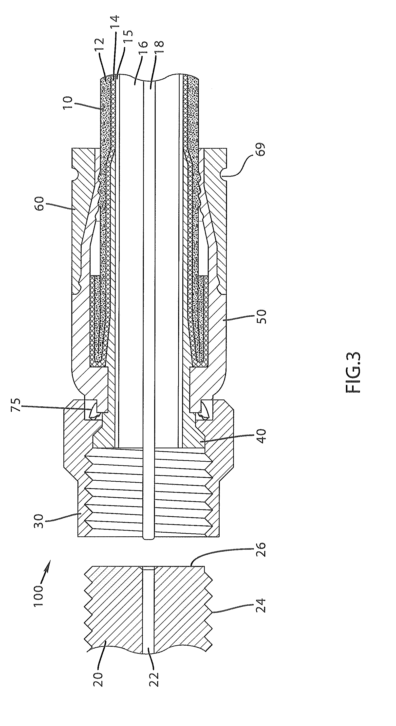
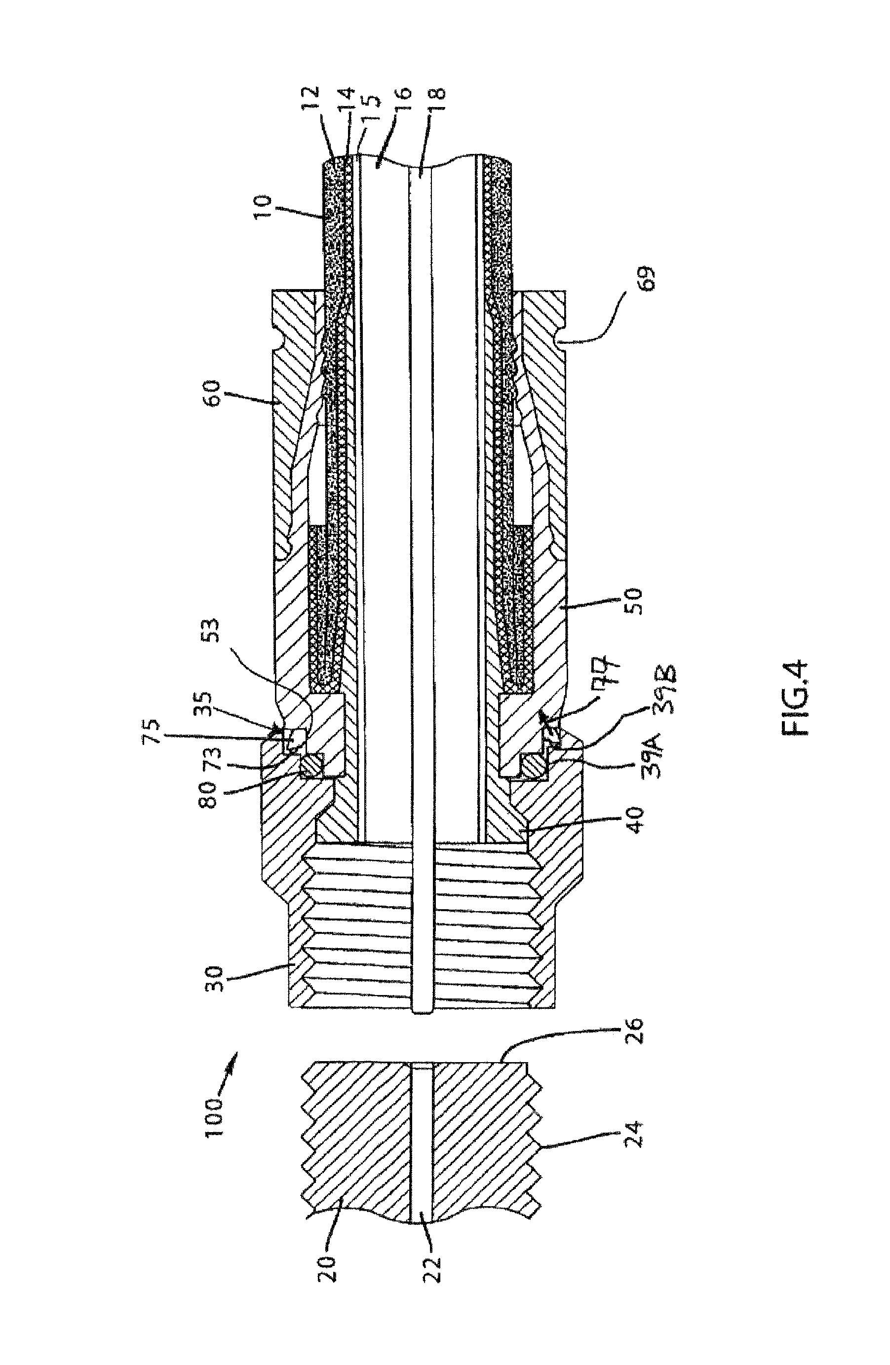
1. A coaxial cable connector comprising: a body having an outward facing body surface; a post having a flange, wherein the post is a separate component from the body; a coupler having an inwardly projecting internal lip configured to rotate about the flange of the post when the connector is in an assembled state, the lip having a forward facing lip surface and a rearward facing lip surface, an inward facing coupler surface extending rearward from the rearward facing lip surface, and a rearward facing coupler surface located rearward of the rearward facing lip surface; and a continuity member configured to contact the rearward facing coupler surface and the outward facing body surface when the connector is in the assembled state, wherein the continuity member is located rearward of the inward facing coupler surface so that no portion of the continuity member is either radially inward of the inward facing coupler surface or radially inward of the outward facing body surface.
2. The coaxial cable connector of claim 1, further comprising a sealing member located forward of the continuity member and configured to form a seal between the inward facing coupler surface and the body when the connector is in the assembled state.
3. The coaxial cable connector of claim 2, wherein the sealing member comprises an O-ring.
4. The coaxial cable connector of claim 1, wherein the continuity member does not contact the rearward facing lip surface when the connector is in the assembled state.
5. The coaxial cable connector of claim 1, wherein the continuity member does not contact the inward facing coupler surface when the connector is in the assembled state.
6. The coaxial cable connector of claim 1, wherein the inward facing coupler surface extends rearward between the rearward facing lip surface and the rearward facing coupler surface.
7. The coaxial cable connector of claim 6, wherein the rearward facing coupler surface extends from the inward facing coupler surface.
8. The coaxial cable connector of claim 1, wherein a portion of the body extends inside the inward facing coupler surface when the connector is in the assembled state.
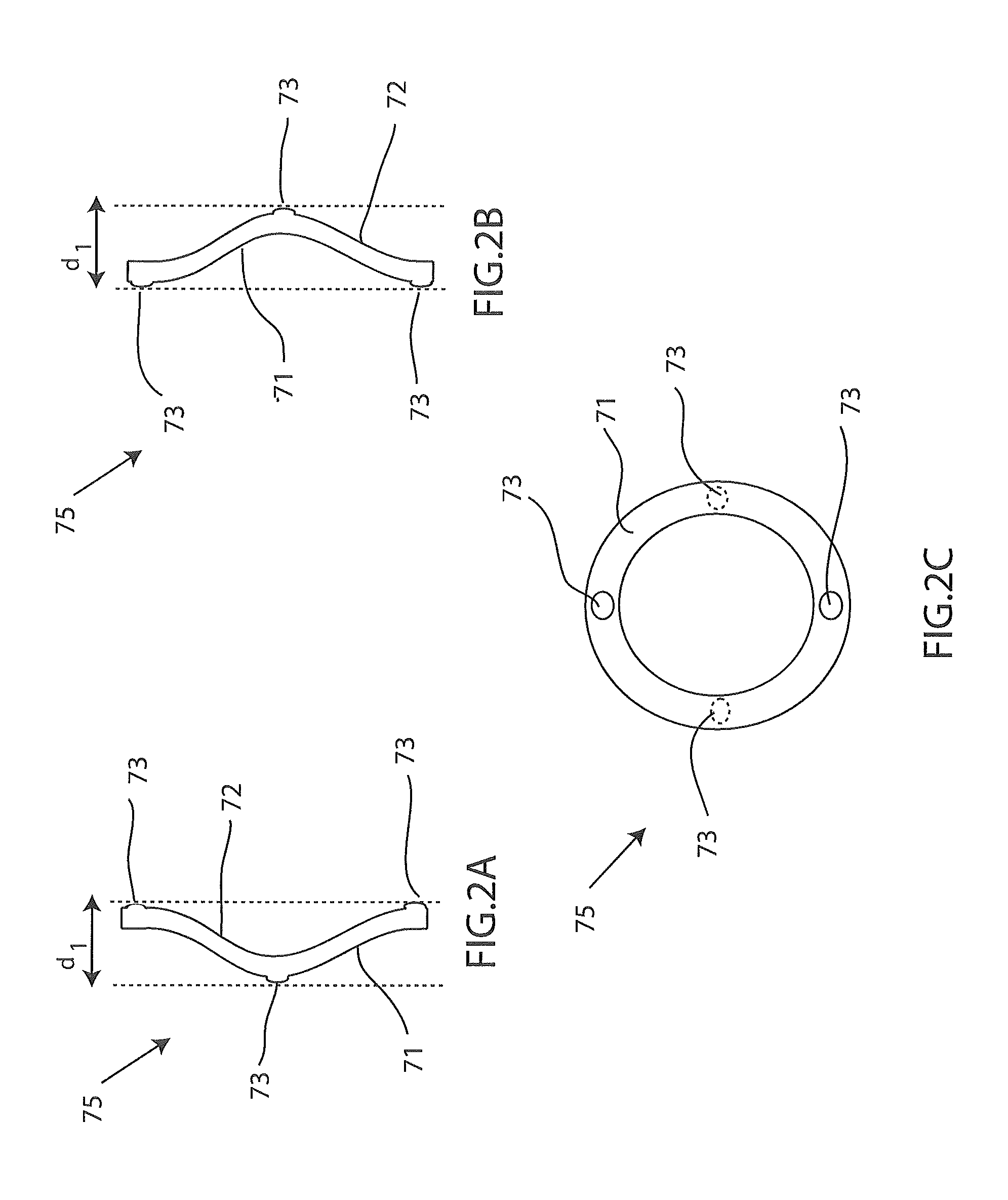
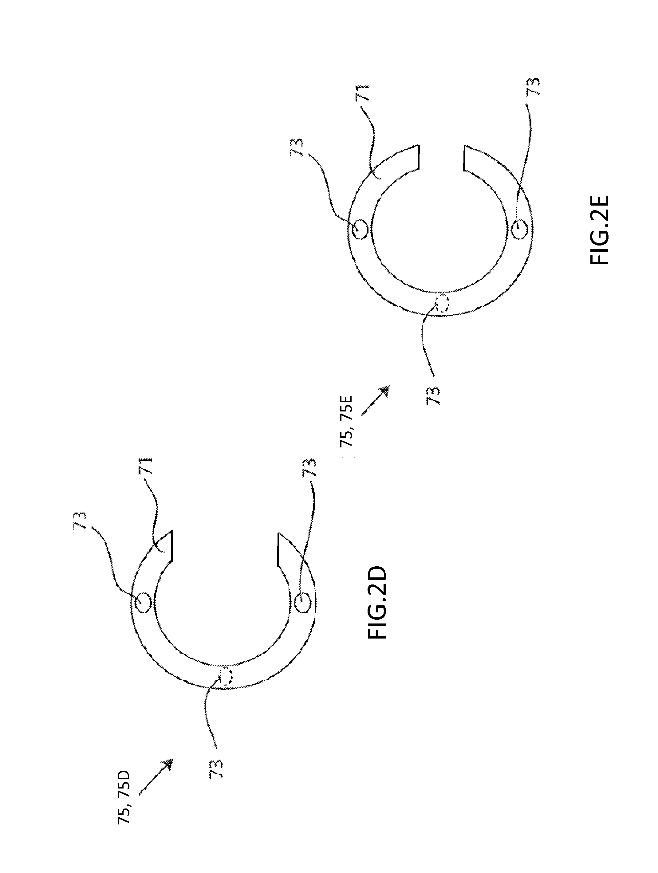
9. The coaxial cable connector of claim 1, wherein the continuity member is C-shaped.
10. The coaxial cable connector of claim 1, wherein the continuity member is configured to form a continuity ground path between the coupler and the body even when the connector is in a loosely assembled state.
11. The coaxial cable connector of claim 1, wherein the continuity member is configured to form a consistent ground path between the coupler and the body even when the connector is in a loosely assembled state.
12. The coaxial cable connector of claim 1, wherein the continuity member is configured to form a constant ground path between the coupler and the body when a ground path does not extend between the coupler and the post.
13. The coaxial cable connector of claim 1, wherein the continuity member is configured to form a continuity ground path between the coupler and the body when a ground path does not extend between the coupler and the post.
14. The coaxial cable connector of claim 1, wherein the continuity member is configured to form a consistent ground path between the coupler and the body when the coupler and the post are not in direct electrical contact with one another and when the coupler and the body are not in direct electrical contact with one another.
15. The coaxial cable connector of claim 1, wherein the continuity member is configured to form a consistent ground path between the coupler and the body when the coupler and the post do not contact one another and when the coupler and the body do not contact one another.
16. The coaxial cable connector of claim 1, wherein the rearward facing coupler surface is configured to face toward a rearward end of the coaxial cable connector.
17. The coaxial cable connector of claim 1, wherein the rearward facing coupler surface is configured to face away from an interface port when the coaxial cable connector is coupled to the interface port.
18. The coaxial cable connector of claim 1, wherein the coaxial cable connector has a rearward end portion and a forward end portion configured to be coupled to an interface port, and wherein the rearward facing coupler surface is configured to face toward the rearward end portion of the coaxial cable connector when the coaxial cable connector is in the assembled state.
19. The coaxial cable connector of claim 1, wherein the coupler has a forward coupler end portion configured to be attached to an interface port and a rearward coupler end portion, and wherein the inward facing coupler surface is configured to rearwardly extend from the rearward facing lip surface to the rearward coupler end portion.
20. The coaxial cable connector of claim 1, wherein the inward facing coupler surface is configured to extend from the rearward facing lip surface toward a rearward direction away from an interface port when the coupler is coupled to the interface port.
21. The coaxial cable connector of claim 1, wherein the inward facing coupler surface comprises a first inward facing coupler surface, wherein the coupler includes a second inward facing coupler surface extending rearward from the rearward facing coupler surface and configured to partially define a cavity when the coaxial cable connector is in the assembled state, and the continuity member is configured to be at least partially located in the cavity when the coaxial cable connector is in the assembled state.
22. The coaxial cable connector of claim 1, wherein the inward facing coupler surface comprises a first inward facing coupler surface, and wherein the coupler includes a second inward facing coupler surface extending rearward from the rearward facing coupler surface and configured to at least partially encircle the continuity member when the coaxial cable connector is in the assembled state.
23. The coaxial cable connector of claim 1, wherein the outward facing body surface has a forward end portion that is configured to at least partially face toward an interface port when the coaxial cable connector is coupled to the interface port.
24. The coaxial cable connector of claim 1, wherein the outward facing body surface at least partially faces a forward direction toward an interface port.
25. The coaxial cable connector of claim 1, wherein the coupler includes an outer rearward coupler portion, wherein the body includes a forward body portion that is configured to be encircled by the outer rearward coupler portion and a rearward body portion that is located rearward from the forward body portion, and wherein the outward facing body surface is located between the forward body portion and the rearward body portion.
26. The coaxial cable connector of claim 1, wherein the outward facing body surface includes a continuity member engaging body portion, wherein the body includes a forward body portion located forward from the continuity member engaging body portion, and wherein the coupler includes an outer coupler portion that is configured to encircle the forward body portion without encircling the continuity member engaging body portion when the coaxial cable connector is in the assembled state.
27. The coaxial cable connector of claim 1, wherein the continuity member does not contact the coupler at a location inside of the coupler.
28. The coaxial cable connector of claim 1, wherein the continuity member is located outside of the coupler and outside of the body.
29. The coaxial cable connector of claim 1, wherein the coupler has a forward end configured to be attached to an interface port and a rearward end, wherein rearward comprises a direction away from the interface port when the coupler is coupled to the interface port, and wherein forward comprises a direction toward the interface port when the coupler is coupled to the interface port.
30. The coaxial cable connector of claim 29, wherein the inward facing coupler surface is configured to extend from the rearward facing lip surface to a location between the forward end and the rearward end.
31. A coaxial cable connector comprising: a body having an outer body surface, and configured to engage a coaxial cable; a post configured to engage the coaxial cable; a coupler having an inward facing coupler surface, and a rearward facing coupler surface located rearward of the inward facing coupler surface, the rearward facing coupler surface configured to face at least a portion of the body; a continuity member located rearward of the inward facing coupler surface such that no portion of the continuity member is located either inward from the inward facing coupler surface or inward from the outer body surface; and wherein the continuity member is configured to maintain electrical contact with the rearward facing coupler surface and with the outer body surface so as to form a continuity ground path between the coupler and the body when the connector is in an assembled state, when the coupler does not physically contact the post, and when the coupler does not physically contact the body.
32. The coaxial cable connector of claim 31, wherein the post includes a flange.
33. The coaxial cable connector of claim 32, wherein the coupler includes an inward projecting lip configured to rotate about the flange of the post when the connector is in the assembled state, the inward projecting lip including a forward facing lip surface and a rearward facing lip surface.
34. The coaxial cable connector of claim 32, further comprising a sealing member located forward of the continuity member and configured to form a seal between the inward facing coupler surface and the body when the connector is in the assembled state.
35. The coaxial cable connector of claim 34, wherein the sealing member comprises an O-ring.
36. The coaxial cable connector of claim 33, wherein the continuity member does not contact the rearward facing lip surface when the connector is in the assembled state.
37. The coaxial cable connector of claim 31, wherein the continuity member does not contact the inward facing coupler surface when the connector is in the assembled state.
38. The coaxial cable connector of claim 33, wherein the inward facing coupler surface extends rearward between the rearward facing lip surface and the rearward facing coupler surface.
39. The coaxial cable connector of claim 38, wherein the rearward facing coupler surface extends from the inward facing coupler surface.
40. The coaxial cable connector of claim 31, wherein the at least portion of the body faced by the rearward facing coupler surface includes a first portion of the body, a second portion of the body extending inside the inward facing coupler surface when the connector is in the assembled state.
41. The coaxial cable connector of claim 31, wherein the continuity member is C-shaped.
42. The coaxial cable connector of claim 31, wherein the rearward facing coupler surface faces at least partially toward a rearward end of the coaxial cable connector.
43. The coaxial cable connector of claim 31, wherein the rearward facing coupler surface at least partially faces toward a rearward end of the coaxial cable connector.
44. The coaxial cable connector of claim 31, wherein the rearward facing coupler surface faces away from an interface port when the coaxial cable connector is coupled to the interface port.
45. The coaxial cable connector of claim 31, wherein the rearward facing coupler surface is configured to face away from an interface port along a direction substantially parallel to a longitudinal direction of the coaxial cable connector when the coaxial cable connector is coupled to the interface port.
46. The coaxial cable connector of claim 31, wherein the coaxial cable connector has a rearward portion and a forward portion configured to be coupled to an interface port, and wherein the rearward facing coupler surface is configured to face toward the rearward portion of the coaxial cable connector when the coaxial cable connector is in the assembled state.
47. The coaxial cable connector of claim 31, wherein the coupler has a forward coupler end portion configured to be coupled to an interface port and a rearward coupler end portion, and wherein the inward facing coupler surface rearwardly extends from the rearward facing lip surface to the rearward coupler end portion.
48. The coaxial cable connector of claim 31, wherein the inward facing coupler surface rearwardly extends from the rearward facing lip surface.
49. The coaxial cable connector of claim 31, wherein the inward facing coupler surface comprises a first inward facing coupler surface, wherein the coupler includes a second inward facing coupler surface that rearwardly extends from the rearward facing coupler surface and partially defines a cavity when the coaxial cable connector is in the assembled state, and wherein the continuity member is at least partially located in the cavity when the coaxial cable connector is in the assembled state.
50. The coaxial cable connector of claim 31, wherein the inward facing coupler surface comprises a first inward facing coupler surface, and wherein the coupler includes a second inward facing coupler surface that rearwardly extends from the rearward facing coupler surface and encircles the continuity member when the coaxial cable connector is in the assembled state.
51. The coaxial cable connector of claim 31, wherein the outer body surface has a forward end portion that at least partially faces toward an interface port when the coaxial cable connector is coupled to the interface port.
52. The coaxial cable connector of claim 31, wherein the outer body surface at least partially faces a forward direction toward an interface port when the coaxial cable connector is coupled to the interface port.
53. The coaxial cable connector of claim 31, wherein the coupler includes a rearward coupler portion, wherein the body includes a forward body portion that is encircled by the rearward coupler portion and a rearward body portion that is located rearward from the forward body portion, and wherein the outer body surface is located between the forward body portion and the rearward body portion.
54. The coaxial cable connector of claim 31, wherein the outer body surface includes a continuity member engaging body portion, wherein the body includes a forward body portion that is located forward from the continuity member engaging body portion, and wherein the coupler includes a rearward coupler portion that encircles the forward body portion without encircling the continuity member engaging body portion when the coaxial cable connector is in the assembled state.
55. The coaxial cable connector of claim 31, wherein the continuity member does not contact the coupler at a location inside of the coupler.
56. The coaxial cable connector of claim 31, wherein the continuity member is located outside of the coupler and outside of the body.
57. The coaxial cable connector of claim 31, wherein the coupler has a forward facing lip surface at least partially facing toward an interface port, a rearward facing lip surface at least partially facing away from the interface port, and a forward end configured to be attached to the interface port, wherein rearward comprises a direction away from the interface port when the coupler is coupled to the interface port, and wherein forward comprises a direction toward the interface port when the coupler is coupled to the interface port.
58. The coaxial cable connector of claim 57, wherein the inward facing coupler surface is configured to extend from the rearward facing lip surface to a location between the forward end and a rearward end of the coupler.
59. A coaxial cable connector comprising: a body having an outward facing body surface; a post having a flange, wherein the post is a separate component from the body; a coupler having an inwardly projecting internal lip configured to rotate about the flange of the post when the connector is in an assembled state, the lip having a forward facing lip surface and a rearward facing lip surface, an inward facing coupler surface extending rearward from the rearward facing lip surface, and a rearward facing coupler surface located rearward of the rearward facing lip surface; and a continuity member configured to contact the rearward facing coupler surface and the outward facing body surface when the connector is in the assembled state, wherein the continuity member is located rearward of the inward facing coupler surface so that no portion of the continuity member is either radially inward of the inward facing coupler surface or radially inward of the outward facing body surface, wherein the continuity member does not contact either the rearward facing lip surface or the inward facing coupler surface when the connector is in the assembled state; and an O-ring located forward of the continuity member and configured to form a seal between the inward facing coupler surface and the body when the connector is in the assembled state.
60. The coaxial cable connector of claim 59, wherein the inward facing coupler surface extends rearward between the rearward facing lip surface and the rearward facing coupler surface.
61. The coaxial cable connector of claim 60, wherein the rearward facing coupler surface extends from the inward facing coupler surface.
62. The coaxial cable connector of claim 59, wherein a portion of the body extends inside the inward facing coupler surface when the connector is in the assembled state.
63. The coaxial cable connector of claim 59, wherein the continuity member is C-shaped.
64. The coaxial cable connector of claim 59, wherein the continuity member is configured to form a continuity ground path between the coupler and the body even when the connector is in a loosely assembled state.
65. The coaxial cable connector of claim 59, wherein the continuity member is configured to form a consistent ground path between the coupler and the body even when the connector is in a loosely assembled state.
66. The coaxial cable connector of claim 59, wherein the continuity member is configured to form a constant ground path between the coupler and the body when a ground path does not extend between the coupler and the post.
67. The coaxial cable connector of claim 59, wherein the continuity member is configured to form a continuity ground path between the coupler and the body when a ground path does not extend between the coupler and the post.
68. The coaxial cable connector of claim 59, wherein the continuity member is configured to form a continuity ground path between the coupler and the body when the coupler and the post are not in direct electrical contact with one another and when the coupler and the body are not in direct electrical contact with one another.
69. The coaxial cable connector of claim 59, wherein the continuity member is configured to form a consistent ground path between the coupler and the body when the coupler and the post do not physically contact one another and when the coupler and the body do not physically contact one another.
70. The coaxial cable connector of claim 59, wherein the rearward facing coupler surface is configured to at least partially face toward a rearward end of the coaxial cable connector.
71. The coaxial cable connector of claim 59, wherein the rearward facing coupler surface is configured to at least partially face away from an interface port when the coaxial cable connector is coupled to the interface port.
72. The coaxial cable connector of claim 59, wherein the rearward facing coupler surface at least partially faces a forward direction toward an interface port.
73. The coaxial cable connector of claim 59, wherein the rearward facing coupler surface at least partially faces toward a rearward end of the coaxial cable connector.
74. The coaxial cable connector of claim 59, wherein the coaxial cable connector has a rearward end portion and a forward end portion configured to be coupled to an interface port, and wherein the rearward facing coupler surface at least partially faces toward the rearward end portion of the coaxial cable connector when the coaxial cable connector is in the assembled state.
75. The coaxial cable connector of claim 59, wherein the coupler has a forward coupler end portion configured to be coupled to an interface port and a rearward coupler end portion, and wherein the inward facing coupler surface rearwardly extends from the rearward facing lip surface to the rearward coupler end portion.
76. The coaxial cable connector of claim 59, wherein the inward facing coupler surface rearwardly extends from the rearward facing lip surface at least partially parallel to a longitudinal axis of the coaxial cable connector.
77. The coaxial cable connector of claim 59, wherein the inward facing coupler surface comprises a first inward facing coupler surface, wherein the coupler includes a second inward facing coupler surface that extends rearward from the rearward facing coupler surface and partially defines a cavity when the coaxial cable connector is in the assembled state, and wherein the continuity member is at least partially located in the cavity when the coaxial cable connector is in the assembled state.
78. The coaxial cable connector of claim 59, wherein the inward facing coupler surface comprises a first inward facing coupler surface, and wherein the coupler includes a second inward facing coupler surface that extends rearward from the rearward facing coupler surface and encircles the continuity member when the coaxial cable connector is in the assembled state.
79. The coaxial cable connector of claim 59, wherein the outward facing body surface has a forward portion that at least partially faces toward an interface port when the coaxial cable connector is coupled to the interface port.
80. The coaxial cable connector of claim 59, wherein the outward facing body surface at least partially faces a forward direction toward an interface port.
81. The coaxial cable connector of claim 59, wherein the coupler includes a rearward coupler portion, wherein the body includes a forward body portion that is encircled by the rearward coupler portion and a rearward body portion that is located rearward from the forward body portion, and wherein the outward facing body surface is located between the forward body portion and the rearward body portion.
82. The coaxial cable connector of claim 59, wherein the outward facing body surface includes a continuity member engaging body portion, wherein the body includes a forward body portion that is located forward from the continuity member engaging body portion, and wherein the coupler includes a rearward coupler portion that encircles the forward body portion without encircling the continuity member engaging body portion when the coaxial cable connector is in the assembled state.
83. The coaxial cable connector of claim 59, wherein the continuity member does not contact the coupler at a location inside of the coupler.
84. The coaxial cable connector of claim 59, wherein the continuity member is located outside of the coupler and outside of the body.
85. The coaxial cable connector of claim 59, wherein the coupler has a forward end configured to be attached to an interface port and a rearward end, wherein rearward comprises a direction away from the interface port when the coupler is coupled to the interface port, and wherein forward comprises a direction toward the interface port when the coupler is coupled to the interface port.
86. The coaxial cable connector of claim 85, wherein the inward facing coupler surface is configured to extend from the rearward facing lip surface to a location between the forward end and the rearward end.
87. A coaxial cable connector comprising: a body having an outward facing body surface; a post having a flange, wherein the post is a separate component from the body; a coupler having an inwardly projecting internal lip configured to rotate about the flange of the post when the connector is in an assembled state, the lip having a forward facing lip surface and a rearward facing lip surface, an inward facing coupler surface extending rearward from the rearward facing lip surface, and a continuity engaging coupler surface, at least a portion of which is located rearward of the rearward facing lip surface; and a continuity member configured to contact the continuity engaging coupler surface and the outward facing body surface when the connector is in the assembled state, wherein the continuity member is located outside of the inward facing coupler surface so that no portion of the continuity member is either radially inward of the inward facing coupler surface or radially inward of the outward facing body surface.
88. The coaxial cable connector of claim 87, further comprising a sealing member located forward of at least a portion of the continuity member and configured to form a seal between the inward facing coupler surface and the body when the connector is in the assembled state.
89. The coaxial cable connector of claim 88, wherein the sealing member comprises an O-ring.
90. The coaxial cable connector of claim 87, wherein the continuity member does not contact the rearward facing lip surface when the connector is in the assembled state.
91. The coaxial cable connector of claim 87, wherein the continuity member does not contact the inward facing coupler surface when the connector is in the assembled state.
92. The coaxial cable connector of claim 87, wherein the continuity engaging coupler surface is a rearward facing coupler surface.
93. The coaxial cable connector of claim 92, wherein the inward facing coupler surface extends rearward between the rearward facing lip surface and the continuity engaging coupler surface.
94. The coaxial cable connector of claim 93, wherein the continuity engaging coupler surface extends from the inward facing coupler surface.
95. The coaxial cable connector of claim 87, wherein a portion of the body extends inside the inward facing coupler surface when the connector is in the assembled state.
96. The coaxial cable connector of claim 87, wherein the continuity member is C-shaped.
97. The coaxial cable connector of claim 87, wherein the continuity engaging coupler surface comprises a rearward facing coupler surface that at least partially faces toward a rearward end of the coaxial cable connector.
98. The coaxial cable connector of claim 87, wherein the continuity engaging coupler surface comprises a rearward facing coupler surface that at least partially faces away from an interface port when the coaxial cable connector is coupled to the interface port.
99. The coaxial cable connector of claim 87, wherein the continuity engaging coupler surface comprises a rearward facing coupler surface that faces away from an interface port when the coaxial cable connector is coupled to the interface port.
100. The coaxial cable connector of claim 87, wherein the coaxial cable connector has a rearward end portion and a forward end portion configured to be coupled to an interface port, and wherein the continuity engaging coupler surface comprises a rearward facing coupler surface that faces toward the rearward end portion of the coaxial cable connector when the coaxial cable connector is in the assembled state.
101. The coaxial cable connector of claim 87, wherein the coupler has a forward coupler end portion configured to be coupled to an interface port and a rearward coupler end portion, and wherein the inward facing coupler surface rearwardly extends from the rearward facing lip surface to the rearward coupler end portion.
102. The coaxial cable connector of claim 87, wherein the inward facing coupler surface is configured to rearwardly extend from the rearward facing lip surface at least along a direction parallel to a longitudinal direction of the coaxial cable connector.
103. The coaxial cable connector of claim 87, wherein the inward facing coupler surface comprises a first inward facing coupler surface, wherein the coupler includes a second inward facing coupler surface that rearwardly extends from the continuity engaging coupler surface and partially defines a cavity when the coaxial cable connector is in the assembled state, and wherein the continuity member is at least partially located in the cavity.
104. The coaxial cable connector of claim 87, wherein the inward facing coupler surface comprises a first inward facing coupler surface, and wherein the coupler includes a second inward facing coupler surface that rearwardly extends from the continuity engaging coupler surface and encircles the continuity member when the coaxial cable connector is in the assembled state.
105. The coaxial cable connector of claim 87, wherein the outward facing body surface has a forward end portion that is configured to at least partially face toward an interface port when the coaxial cable connector is coupled to the interface port.
106. The coaxial cable connector of claim 87, wherein the outward facing body surface at least partially faces a forward direction toward an interface port.
107. The coaxial cable connector of claim 87, wherein the coupler includes a rearward coupler portion, wherein the body includes a forward body portion that is encircled by the rearward coupler portion and a rearward body portion that is located rearward from the forward body portion, and wherein the outward facing body surface is located between the forward body portion and the rearward body portion.
108. The coaxial cable connector of claim 87, wherein the outward facing body surface includes a continuity member engaging body portion, wherein the body includes a forward body portion that is located forward from the continuity member engaging body portion, and wherein the coupler includes an outer coupler portion that encircles the forward body portion without encircling the continuity member engaging body portion when the coaxial cable connector is in the assembled state.
109. The coaxial cable connector of claim 87, wherein the continuity member does not contact the coupler at a location inside of the coupler.
110. The coaxial cable connector of claim 87, wherein the continuity member is located outside of the coupler and outside of the body.
111. The coaxial cable connector of claim 87, wherein the coupler has a forward end configured to be coupled to an interface port and a rearward end, wherein rearward comprises a direction away from the interface port when the coupler is coupled to the interface port, and wherein forward comprises a direction toward the interface port when the coupler is coupled to the interface port.
112. The coaxial cable connector of claim 111, wherein the inward facing coupler surface is configured to extend from the rearward facing lip surface to a location between the forward end and the rearward end.
113. A coaxial cable connector comprising: a body having an outer body surface, and configured to engage a coaxial cable; a post configured to engage the coaxial cable; a coupler having an inward facing coupler surface, and a continuity engaging coupler surface having a portion located rearward from the inward facing coupler surface; and a continuity member located rearward from the inward facing coupler surface such that no portion of the continuity member is located either inward from the inward facing coupler surface or inward from the outer body surface; and wherein the continuity member is configured to maintain electrical contact with the continuity engaging coupler surface and with the outer body surface when the connector is in an assembled state, and when the coupler and the post are not in physical contact with each other; wherein rearward comprises a direction away from an interface port when the coupler is coupled to the interface port; and wherein forward comprises a direction toward the interface port when the coupler is coupled to the interface port.
114. The coaxial cable connector of claim 113, wherein the post includes a flange, and is a separate component from the body, and the coupler includes an inwardly projecting internal lip configured to rotate about the flange of the post when the connector is in the assembled state, the inwardly projecting lip having a forward facing lip surface and a rearward facing lip surface, and the inward facing coupler surface extends rearward from the rearward facing lip surface.
115. The coaxial cable connector of claim 113, further comprising a sealing member located forward of at least a portion of the continuity member and configured to form a seal between the inward facing coupler surface and the body when the connector is in the assembled state.
116. The coaxial cable connector of claim 115, wherein the sealing member comprises an O-ring.
117. The coaxial cable connector of claim 113, wherein the continuity member does not contact the rearward facing lip surface when the connector is in the assembled state.
118. The coaxial cable connector of claim 113, wherein the continuity member does not contact the inward facing coupler surface when the connector is in the assembled state.
119. The coaxial cable connector of claim 113, wherein the continuity engaging coupler surface is a rearward facing coupler surface.
120. The coaxial cable connector of claim 119, wherein the inward facing coupler surface extends rearward between the rearward facing lip surface and the continuity engaging coupler surface.
121. The coaxial cable connector of claim 120, wherein the continuity engaging coupler surface extends from the inward facing coupler surface.
122. The coaxial cable connector of claim 113, wherein a portion of the body extends inside the inward facing coupler surface when the connector is in the assembled state.
123. The coaxial cable connector of claim 113, wherein the continuity member is C-shaped.
124. The coaxial cable connector of claim 113, wherein the continuity member is configured to form a continuity ground path between the coupler and the body even when the connector is in a loosely assembled state.
125. The coaxial cable connector of claim 113, wherein the continuity member is configured to form a consistent ground path between the coupler and the body even when the connector is in a loosely assembled state.
126. The coaxial cable connector of claim 113, wherein the coupler is configured to rotate about the post and the coupler, and wherein the continuity member is configured to maintain a constant ground path between the coupler and the body when the coupler rotates about the post.
127. The coaxial cable connector of claim 113, wherein the continuity member is configured to form a continuity ground path between the coupler and the body when a ground path does not extend between the coupler and the post.
128. The coaxial cable connector of claim 113, wherein the coupler is configured to rotate about the post, and wherein the continuity member is configured to maintain electrical continuity between the coupler and the body when the coupler rotates about the post and when the coupler and the body are not in direct electrical contact with one another.
129. The coaxial cable connector of claim 113, wherein the continuity member is configured to maintain a continuous and non-intermittent ground path between the coupler and the body when the coupler and the post do not physically contact one another and when the coupler and the body do not physically contact one another.
130. The coaxial cable connector of claim 113, wherein the continuity engaging coupler surface comprises a rearward facing coupler surface that at least partially faces toward a rearward end of the coaxial cable connector.
131. The coaxial cable connector of claim 113, wherein the continuity engaging coupler surface comprises a rearward facing coupler surface that at least partially faces toward a rearward direction.
132. The coaxial cable connector of claim 113, wherein the continuity engaging coupler surface comprises a rearward facing coupler surface that at least partially faces away from the interface port when the coaxial cable connector is coupled to the interface port.
133. The coaxial cable connector of claim 113, wherein the coaxial cable connector has a rearward end portion and a forward end portion configured to be coupled to an interface port, and wherein the continuity engaging coupler surface comprises a rearward facing coupler surface that at least partially faces toward the rearward end portion of the coaxial cable connector when the coaxial cable connector is in the assembled state.
134. The coaxial cable connector of claim 113, wherein the coupler has a forward coupler end portion that is configured to be coupled to the interface port and a rearward coupler end portion, and wherein the inward facing coupler surface rearwardly extends to the rearward coupler end portion.
135. The coaxial cable connector of claim 113, wherein the coupler includes an inward lip having a rearward facing lip surface, and wherein the inward facing coupler surface rearwardly extends from the rearward facing lip surface.
136. The coaxial cable connector of claim 113, wherein the inward facing coupler surface comprises a first inward facing coupler surface, wherein the coupler includes a second inward facing coupler surface that extends rearward from the continuity engaging coupler surface and partially defines a cavity when the coaxial cable connector is in the assembled state, and wherein the continuity member is at least partially located in the cavity when the coaxial cable connector is in the assembled state.
137. The coaxial cable connector of claim 113, wherein the inward facing coupler surface comprises a first inward facing coupler surface, and wherein the coupler includes a second inward facing coupler surface that extends rearward from the continuity engaging coupler surface and encircles the continuity member when the coaxial cable connector is in the assembled state.
138. The coaxial cable connector of claim 113, wherein the outer body surface has a forward portion that at least partially faces toward an interface port when the coaxial cable connector is coupled to the interface port.
139. The coaxial cable connector of claim 113, wherein the outer body surface at least partially faces a forward direction toward an interface port.
140. The coaxial cable connector of claim 113, wherein the coupler includes a rearward coupler portion, wherein the body includes a forward body portion that is encircled by the rearward coupler portion, the body also including a rearward body portion that is located rearward from the forward body portion, and the outer body surface is located between the forward body portion and the rearward body portion.
141. The coaxial cable connector of claim 113, wherein the outer body surface includes a continuity member engaging body portion, wherein the body includes a forward body portion that is located forward from the continuity member engaging body portion, and wherein the coupler includes an outer coupler portion that encircles the forward body portion without encircling the continuity member engaging body portion when the coaxial cable connector is in the assembled state.
142. The coaxial cable connector of claim 113, wherein the continuity member does not contact the coupler at a location inside of the coupler.
143. The coaxial cable connector of claim 113, wherein the continuity member is located outside of the coupler and outside of the body.
144. The coaxial cable connector of claim 113, wherein the coupler has a forward facing lip surface, a rearward facing lip surface, a forward end configured to be coupled to an interface port, and a rearward end, wherein rearward comprises a direction away from the interface port when the coupler is coupled to the interface port, and wherein forward comprises a direction toward the interface port when the coupler is coupled to the interface port.
145. The coaxial cable connector of claim 144, wherein the inward facing coupler surface is configured to extend from the rearward facing lip surface to a location between the forward end and the rearward end.
146. A coaxial cable connector comprising: a body having an outer body surface, and configured to engage a coaxial cable; a post configured to engage the coaxial cable; a coupler having an inward facing coupler surface, and a continuity engaging coupler surface having a portion located outward from the inward facing coupler surface; and a continuity member located outward from the inward facing coupler surface such that no portion of the continuity member is located either inward from the inward facing coupler surface or inward from the outer body surface; and wherein the continuity member is configured to maintain electrical contact with the continuity engaging coupler surface and with the outer body surface when the connector is in an assembled state, and when the coupler and the post are not in physical contact with each other.
147. The coaxial cable connector of claim 146, wherein the post includes a flange, and is a separate component from the body, and the coupler includes an inwardly projecting internal lip configured to rotate about the flange of the post when the connector is in the assembled state, the inwardly projecting lip having a forward facing lip surface and a rearward facing lip surface, and the inward facing coupler surface extends rearward from the rearward facing lip surface.
148. The coaxial cable connector of claim 146, further comprising a sealing member located forward of at least a portion of the continuity member and configured to form a seal between the inward facing coupler surface and the body when the connector is in the assembled state.
149. The coaxial cable connector of claim 148, wherein the sealing member comprises an O-ring.
150. The coaxial cable connector of claim 146, wherein the continuity member does not contact the rearward facing lip surface when the connector is in the assembled state.
151. The coaxial cable connector of claim 146, wherein the continuity member does not contact the inward facing coupler surface when the connector is in the assembled state.
152. The coaxial cable connector of claim 146, wherein the continuity engaging coupler surface is a rearward facing coupler surface.
153. The coaxial cable connector of claim 146, wherein the inward facing coupler surface extends rearward between the rearward facing lip surface and the continuity engaging coupler surface.
154. The coaxial cable connector of claim 153, wherein the continuity engaging coupler surface extends from the inward facing coupler surface.
155. The coaxial cable connector of claim 146, wherein a portion of the body extends inside the inward facing coupler surface when the connector is in the assembled state.
156. The coaxial cable connector of claim 146, wherein the continuity member is C-shaped.
157. The coaxial cable connector of claim 146, wherein the continuity member is configured to form a continuity ground path between the coupler and the body even when the connector is in a loosely assembled state.
158. The coaxial cable connector of claim 146, wherein the continuity member is configured to form a consistent ground path between the coupler and the body even when the connector is in a loosely assembled state.
159. The coaxial cable connector of claim 146, wherein the continuity member is configured to form a constant ground path between the coupler and the body when a ground path does not extend between the coupler and the post.
160. The coaxial cable connector of claim 146, wherein the continuity member is configured to form a continuity ground path between the coupler and the body when a ground path does not extend between the coupler and the post.
161. The coaxial cable connector of claim 146, wherein the continuity member is configured to form a continuity ground path between the coupler and the body when the coupler and the post are not in direct electrical contact with one another and when the coupler and the body are not in direct electrical contact with one another.
162. The coaxial cable connector of claim 146, wherein the continuity member is configured to form a consistent ground path between the coupler and the body when the coupler and the post do not physically contact one another and when the coupler and the body do not physically contact one another.
163. The coaxial cable connector of claim 146, wherein the continuity engaging coupler surface at least partially faces toward a rearward end of the coaxial cable connector.
164. The coaxial cable connector of claim 146, wherein the coupler has a forward coupler end portion configured to be attached to an interface port and a rearward coupler end portion, and wherein the inward facing coupler surface rearwardly extends to the rearward coupler end portion.
165. The coaxial cable connector of claim 146, wherein the outer body surface has a forward portion that at least partially faces toward an interface port when the coaxial cable connector is coupled to the interface port.
166. The coaxial cable connector of claim 146, wherein the outer body surface at least partially faces a forward direction toward an interface port.
167. The coaxial cable connector of claim 146, wherein the coupler includes a rearward coupler portion, wherein the body includes a forward body portion that is encircled by the rearward coupler portion and a rearward body portion that is located rearward from the forward body portion, and wherein the outer body surface is located between the forward body portion and the rearward body portion.
168. The coaxial cable connector of claim 146, wherein the outer body surface includes a continuity member engaging body portion, wherein the body includes a forward body portion that is located forward from the continuity member engaging body portion, and wherein the coupler includes an outer coupler portion that encircles the forward body portion without encircling the continuity member engaging body portion when the coaxial cable connector is in the assembled state.
169. The coaxial cable connector of claim 146, wherein the continuity member does not contact the coupler at a location inside of the coupler.
170. The coaxial cable connector of claim 146, wherein the continuity member is located outside of the coupler and outside of the body.
171. The coaxial cable connector of claim 146, wherein the coupler has a forward facing lip surface, a rearward facing lip surface, a forward end configured to be coupled to an interface port, and a rearward end, wherein rearward comprises a direction away from the interface port when the coupler is coupled to the interface port, and wherein forward comprises a direction toward the interface port when the coupler is coupled to the interface port.
172. The coaxial cable connector of claim 171, wherein the inward facing coupler surface is configured to extend from the rearward facing lip surface to a location between the forward end and the rearward end.
173. A coaxial cable connector comprising: a body having an outward facing body surface; a post having a flange, wherein the post is a separate component from the body; a coupler having an inwardly projecting internal lip configured to rotate about the flange of the post when the connector is in an assembled state, the lip having a forward facing lip surface and a rearward facing lip surface, an inward facing coupler surface extending rearward from the rearward facing lip surface, and a continuity engaging coupler surface, at least a portion of which is located rearward of the rearward facing lip surface; a continuity member configured to contact the continuity engaging coupler surface and the outward facing body surface when the connector is in the assembled state, wherein the continuity member is located outside of the inward facing coupler surface so that no portion of the continuity member is either radially inward of the inward facing coupler surface or radially inward of the outward facing body surface, wherein the continuity member does not contact either the rearward facing lip surface or the inward facing coupler surface when the connector is in the assembled state; an O-ring located forward of at least a portion of the continuity member and configured to form a seal between the inward facing coupler surface and the body when the connector is in the assembled state; and wherein rearward comprises a direction away from an interface port when the coupler is coupled to the interface port and forward comprises a direction toward the interface port when the coupler is coupled to the interface port.
174. The coaxial cable connector of claim 173, wherein the continuity member is discontinuous.
175. The coaxial cable connector of claim 173, wherein the continuity engaging coupler surface is a rearward facing coupler surface.
176. The coaxial cable connector of claim 175, wherein the inward facing coupler surface extends rearward between the rearward facing lip surface and the continuity engaging coupler surface.
177. The coaxial cable connector of claim 176, wherein the continuity engaging coupler surface extends from the inward facing coupler surface.
178. The coaxial cable connector of claim 173, wherein a portion of the body extends inside the inward facing coupler surface when the connector is in the assembled state.
179. The coaxial cable connector of claim 173, wherein the continuity member is C-shaped.
180. The coaxial cable connector of claim 173, wherein the continuity engaging coupler surface at least partially faces toward a rearward end of the coaxial cable connector.
181. The coaxial cable connector of claim 173, wherein the coupler has a forward coupler end portion configured to be coupled to an interface port and a rearward coupler end portion, and wherein the inward facing coupler surface extends from the rearward coupler end portion.
182. The coaxial cable connector of claim 173, wherein the outward facing body surface has a forward portion that at least partially faces toward an interface port when the coaxial cable connector is coupled to the interface port.
183. The coaxial cable connector of claim 173, wherein the coupler includes a rearward coupler portion, wherein the body includes a forward body portion that is encircled by the rearward coupler portion and a rearward body portion that is located rearward from the forward body portion and is not encircled by the rearward coupler portion, and wherein the outward facing body surface comprises a continuity engaging body surface that is located between the forward body portion and the rearward body portion and is not encircled by the rearward coupler portion.
184. The coaxial cable connector of claim 173, wherein the outward facing body surface includes a continuity member engaging body portion, wherein the body includes a forward body portion that is located forward from the continuity member engaging body portion, and wherein the coupler includes an outer coupler portion that encircles the forward body portion without encircling the continuity member engaging body portion when the coaxial cable connector is in the assembled state.
185. The coaxial cable connector of claim 173, wherein the continuity member does not contact the coupler at a location inside of the coupler.
186. The coaxial cable connector of claim 173, wherein the continuity member is located outside of the coupler and outside of the body.
187. The coaxial cable connector of claim 173, wherein the coupler has a forward end configured to be coupled to an interface port and a rearward end, wherein rearward comprises a direction away from the interface port when the coupler is coupled to the interface port, and wherein forward comprises a direction toward the interface port when the coupler is coupled to the interface port.
188. The coaxial cable connector of claim 187, wherein the inward facing coupler surface is configured to extend from the rearward facing lip surface to a location between the forward end and the rearward end.
Description
FIELD OF TECHNOLOGY
The following disclosure relates generally to the field of connectors for coaxial cables. More particularly, to embodiments of a coaxial cable connector having a continuity member that extends electrical continuity through the connector.
BACKGROUND
Broadband communications have become an increasingly prevalent form of electromagnetic information exchange and coaxial cables are common conduits for transmission of broadband communications. Connectors for coaxial cables are typically connected onto complementary interface ports to electrically integrate coaxial cables to various electronic devices. In addition, connectors are often utilized to connect coaxial cables to various communications modifying equipment such as signal splitters, cable line extenders and cable network modules.
To help prevent the introduction of electromagnetic interference, coaxial cables are provided with an outer conductive shield. In an attempt to further screen ingress of environmental noise, typical connectors are generally configured to contact with and electrically extend the conductive shield of attached coaxial cables. Moreover, electromagnetic noise can be problematic when it is introduced via the connective juncture between an interface port and a connector. Such problematic noise interference is disruptive where an electromagnetic buffer is not provided by an adequate electrical and/or physical interface between the port and the connector.
Accordingly, there is a need in the field of coaxial cable connectors for an improved connector design.
SUMMARY
The present invention provides an apparatus for use with coaxial cable connections that offers improved reliability.
A first general aspect relates generally to a coaxial cable connector comprising a connector body attached to a post, wherein the connector body has a first end and a second end, a port coupling element rotatable about the post, the port coupling element separated from the connector body by a distance, and a continuity element positioned between the port coupling element and the connector body proximate the second end of the connector body, wherein the continuity element establishes and maintains electrical continuity between the connector body and the port coupling element.
A second general aspect relates generally to a coaxial cable connector comprising a connector body attached to a post, the connector body having a first end and a second end, wherein the connector body includes an annular outer recess proximate the second end, a port coupling element rotatable about the post, wherein the port coupling element has an internal lip, and a continuity element having a first surface axially separated from a second surface, the first surface contacting the internal lip of the port coupling element and the second surface contacting the outer annular recess of the connector body, wherein the continuity element facilitates grounding of a coaxial cable through the connector.
A third general aspect relates generally to a coaxial cable connector comprising a connector body attached to a post, the connector body having a first end and opposing second end, wherein the connector body includes an annular outer recess proximate the second end, a port coupling element rotatable about the post, wherein the port coupling element has an internal lip, and a means for establishing and maintaining physical and electrical communication between the connector body and the port coupling element.
A fourth general aspect relates generally to a coaxial cable connector comprising a connector body attached to a post, the connector body having a first end and a second end, wherein the connector body includes an annular outer recess proximate the second end, a port coupling element rotatable about the post, wherein the port coupling element has an inner surface, and a continuity element having a first surface and a second surface, the first surface contacting the inner surface of the port coupling element and the second surface contacting the outer annular recess of the connector body, wherein the continuity element establishes and maintains electrical communication between the port coupling element and the connector body in a radial direction.
A fifth general aspect relates generally to a method for facilitating grounding of a coaxial cable through the connector, comprising providing a coaxial cable connector, the coaxial cable connector including: a connector body attached to a post, wherein the connector body has a first end and a second end, and a port coupling element rotatable about the post, the port coupling element separated from the connector body by a distance; and disposing a continuity element positioned between the port coupling element and the connector body proximate the second end of the connector body, wherein the continuity element establishes and maintains electrical continuity between the connector body and the port coupling element.
The foregoing and other features of the invention will be apparent from the following more particular description of various embodiments of the invention.
BRIEF DESCRIPTION OF THE DRAWINGS
Some of the embodiments of this invention will be described in detail, with reference to the following figures, wherein like designations denote like members, wherein:
FIG. 1 depicts an exploded perspective view of an embodiment of a connector having a first embodiment of a nut-body continuity element;
FIG. 2A depicts a first side view of a first embodiment of a nut-body continuity element;
FIG. 2B depicts a second side view of a first embodiment of a nut-body continuity element;
FIG. 2C depicts a front view of a first embodiment of a nut-body continuity element;
FIG. 2D depicts a front view of another embodiment of a continuity element;
FIG. 2E depicts a front view of yet another embodiment of a continuity element;
FIG. 3 depicts a sectional side view of an embodiment of a connector having a first embodiment of a nut-body continuity element;
FIG. 4 depicts a sectional side view of an embodiment of a connector having a first embodiment of a nut-body continuity element and a conductive element;
FIG. 5 depicts a sectional side view of an embodiment of a connector having a first embodiment of a nut-body continuity element inboard of a conductive element;
FIG. 6 depicts a sectional side view of an embodiment of a nut;
FIG. 7 depicts a sectional side view of an embodiment of a post;
FIG. 8 depicts a sectional side view of an embodiment of a connector body;
FIG. 9 depicts a sectional side view of an embodiment of a fastener member;
FIG. 10 depicts a sectional side view of an embodiment of a connector body having an integral post;
FIG. 11 depicts a sectional side view of an embodiment of a connector configured having a first embodiment of a nut-body continuity element with more than one continuity element proximate a second end of a post;
FIG. 12 depicts a sectional side view of an embodiment of a connector configured with a conductive member proximate a second end of a connector body, and a first embodiment of a nut-body continuity element;
FIG. 13 depicts a perspective cut away view of an embodiment of a connector having a second embodiment of a nut-body continuity element;
FIG. 14 depicts a perspective view of a second embodiment of a nut-body continuity element;
FIG. 15 depicts a front view of a second embodiment of a nut-body continuity element; and
FIG. 16 depicts a cross-sectional end view of an embodiment of a connector having a second embodiment of a nut-body continuity element.
DETAILED DESCRIPTION OF DRAWINGS
Although certain embodiments of the present invention will be shown and described in detail, it should be understood that various changes and modifications may be made without departing from the scope of the appended claims. The scope of the present invention will in no way be limited to the number of constituting components, the materials thereof, the shapes thereof, the relative arrangement thereof, etc., and are disclosed simply as an example of an embodiment. The features and advantages of the present invention are illustrated in detail in the accompanying drawings, wherein like reference numerals refer to like elements throughout the drawings.
As a preface to the detailed description, it should be noted that, as used in this specification and the appended claims, the singular forms "a", "an" and "the" include plural referents, unless the context clearly dictates otherwise.
Referring to the drawings, FIG. 1 depicts one embodiment of a connector 100. The connector 100 may include a coaxial cable 10 having a protective outer jacket 12, a conductive grounding shield 14 or shields 14, an interior dielectric 16 (potentially surrounding a conductive foil layer 15), and a center conductor 18. The coaxial cable 10 may be prepared by removing the protective outer jacket 12 and drawing back the conductive grounding shield 14 to expose a portion of the interior dielectric 16 (potentially surrounding a conductive foil layer 15). Further preparation of the embodied coaxial cable 10 may include stripping the dielectric 16 (and potential conductive foil layer 15) to expose a portion of the center conductor 18. The protective outer jacket 12 is intended to protect the various components of the coaxial cable 10 from damage which may result from exposure to dirt or moisture and from corrosion. Moreover, the protective outer jacket 12 may serve in some measure to secure the various components of the coaxial cable 10 in a contained cable design that protects the cable 10 from damage related to movement during cable installation. The conductive grounding shield 14 may be comprised of conductive materials suitable for providing an electrical ground connection. Various embodiments of the shield 14 may be employed to screen unwanted noise. For instance, the shield 14 may comprise several conductive strands formed in a continuous braid around the dielectric 16 (potentially surrounding a conductive foil layer 15). Combinations of foil and/or braided strands may be utilized wherein the conductive shield 14 may comprise a foil layer, then a braided layer, and then a foil layer. Those in the art will appreciate that various layer combinations may be implemented in order for the conductive grounding shield 14 to effectuate an electromagnetic buffer helping to prevent ingress of environmental noise that may disrupt broadband communications. Furthermore, there may be more than one grounding shield 14, such as a tri-shield or quad shield cable, and there may also be flooding compounds protecting the shield 14. The dielectric 16 may be comprised of materials suitable for electrical insulation. It should be noted that the various materials of which all the various components of the coaxial cable 10 are comprised should have some degree of elasticity allowing the cable 10 to flex or bend in accordance with traditional broadband communications standards, installation methods and/or equipment. It should further be recognized that the radial thickness of the coaxial cable 10, protective outer jacket 12, conductive grounding shield 14, interior dielectric 16 and/or center conductor 18 may vary based upon generally recognized parameters corresponding to broadband communication standards and/or equipment.
The conductive foil layer 15 may comprise a layer of foil wrapped or otherwise positioned around the dielectric 16, thus the conductive foil layer 15 may surround and/or encompass the dielectric 16. For instance, the conductive foil layer 15 may be positioned between the dielectric 16 and the shield 14. In one embodiment, the conductive foil layer 15 may be bonded to the dielectric 16. In another embodiment, the conductive foil layer 15 may be generally wrapped around the dielectric 16. The conductive foil layer 15 may provide a continuous uniform outer conductor for maintaining the coaxial condition of the coaxial cable 10 along its axial length. The coaxial cable 10 having, inter alia, a conductive foil layer 15 may be manufactured in thousands of feet of lengths. Furthermore, the conductive foil layer 15 may be manufactured to a nominal outside diameter with a plus minus tolerance on the diameter, and may be a wider range than what may normally be achievable with machined, molded, or cast components. The outside diameter of the conductive foil layer 15 may vary in dimension down the length of the cable 10, thus its size may be unpredictable at any point along the cable 10. Due to this unpredictability, the contact between the post 40 and the conductive foil layer 15 may not be sufficient or adequate for conductivity or continuity throughout the connector 100. Thus, a nut-body continuity element 75 may be placed between the nut 30 and the connector body 50 to allow continuity and/or continuous physical and electrical contact or communication between the nut 30 and the connector body 50. Continuous conductive and electrical continuity between the nut 30 and the connector body 50 can be established by the physical and electrical contact between the connector body 50 and the nut-body continuity element 75, wherein the nut-body continuity element 75 is simultaneously in physical and electrical contact with the nut 30. While operably configured, electrical continuity may be established and maintained throughout the connector 100 and to interface port 20 via the conductive foil layer 15 which contacts the conductive grounding shield 14, which contacts the connector body 50, which contacts the nut-body continuity element 75, which contacts the nut 30, the nut 30 being advanced onto interface port 20. Alternatively, electrical continuity can be established and maintained throughout the connector 100 via the conductive foil layer 15, which contacts the post 40, which contacts the connector body 50, which contacts the nut-body continuity element 75, which contacts the nut 30, the nut 30 being advanced onto interface port 20.
Referring further to FIG. 1, the connector 100 may make contact with a coaxial cable interface port 20. The coaxial cable interface port 20 includes a conductive receptacle 22 for receiving a portion of a coaxial cable center conductor 18 sufficient to make adequate electrical contact. The coaxial cable interface port 20 may further comprise a threaded exterior surface 24. However, various embodiments may employ a smooth surface, as opposed to threaded exterior surface. In addition, the coaxial cable interface port 20 may comprise a mating edge 26. It should be recognized that the radial thickness and/or the length of the coaxial cable interface port 20 and/or the conductive receptacle 22 may vary based upon generally recognized parameters corresponding to broadband communication standards and/or equipment. Moreover, the pitch and height of threads which may be formed upon the threaded exterior surface 24 of the coaxial cable interface port 20 may also vary based upon generally recognized parameters corresponding to broadband communication standards and/or equipment. Furthermore, it should be noted that the interface port 20 may be formed of a single conductive material, multiple conductive materials, or may be configured with both conductive and non-conductive materials corresponding to the port's 20 electrical interface with a connector 100. For example, the threaded exterior surface may be fabricated from a conductive material, while the material comprising the mating edge 26 may be non-conductive or vice versa. However, the conductive receptacle 22 should be formed of a conductive material. Further still, it will be understood by those of ordinary skill that the interface port 20 may be embodied by a connective interface component of a communications modifying device such as a signal splitter, a cable line extender, a cable network module and/or the like.
With continued reference to FIG. 1, an embodiment of the connector 100 may further comprise a nut 30, a post 40, a connector body 50, a fastener member 60, and a nut-body continuity element 75. The nut-body continuity element 75 should be formed of a conductive material. Such conductive materials may include, but are not limited to conductive polymers, conductive plastics, conductive elastomers, conductive elastomeric mixtures, composite materials having conductive properties, metal, soft metals, conductive rubber, and/or the like and/or any operable combination thereof. The nut-body continuity element 75 may be resilient, flexible, elastic, etc., or may be rigid and/or semi-rigid. The nut-body continuity element 75 may have a circular, rectangular, square, or any appropriate geometrically dimensioned cross-section. For example, the nut-body continuity element 75 may have a flat rectangular cross-section similar to a metal washer or wave washer. The nut-body continuity element 75 may also be a conductive element, conductive member, continuity element, a conductive ring, a conductive wave ring, a continuity ring, a continuity wave ring, a resilient member, and the like.
Referring to the drawings, FIGS. 2A-2C depict further embodiments of a nut-body continuity element 75, specifically, embodiments of a structure and/or design of a nut-body continuity element 75. For example, the nut-body continuity element 75 may comprise a substantially circinate torus or toroid structure. Moreover, nut-body continuity element 75 may have a slight bend to provide axial separation between contact points. For instance, the point on first surface 71 of the nut-body continuity element 75 contacting the nut 30 may be an axial distance, d.sub.1, away from the point on the second surface 72 of the nut-body continuity element 75 contacting the connector body 50. To facilitate contact with the connector body 50 and with the nut 30, the nut-body continuity element 75 may have one or more bumps 73 located on the surface of the nut-body continuity element 75. Bumps 73 may be any protrusion from the surface of the nut-body continuity element 75 that can facilitate the contact of the nut 30 and the connector body 50. The surface of the nut-body continuity element 75 can comprise a first surface 71 and a second surface 72; bumps 73 may be located on both the first surface 71 of the nut-body continuity element 75 and the second surface 72 of the nut-body continuity element 75, or just one of the first surface 71 or second surface 72. In some embodiments, the nut-body continuity element 75 does not have any bumps 73 positioned on the surface, and relies on smooth, flat contact offered by the first surface 71 and/or second surface 72. Because of the shape and design of the nut-body continuity element 75 (i.e. because of the bended configuration), the nut-body continuity element 75 should make contact with the nut 30 at two or more points along the first surface 71, and should also make contact with the connector body 50 at two or more points along the second surface 72. Depending on the angle of curvature of the bend, the nut-body continuity element 75 may contact the nut 30 and the connector body 50 at multiple or single locations along the first surface 71 and second surface 72 of the nut-body continuity element 75. The angle of curvature of the bend of the nut-body continuity element 75 may vary, including a nut-body continuity element 75 with little to no axial separation.
Furthermore, a bended configuration of the nut-body continuity element 75 can allow a portion of the nut-body continuity element 75 to physically contact the nut 30 and another portion of the nut-body continuity element 75 to contact the connector body 50 in a biasing relationship. For instance, the bend in the nut-body continuity element 75 can allow deflection of the element when subjected to an external force, such as a force exerted by the nut 30 (e.g. internal lip 36) or the connector body 50 (e.g. outer annular recess 56). The biasing relationship between the nut 30, the connector body 50, and the nut-body continuity element 75, evidenced by the deflection of the nut-body continuity element 75, establishes and maintains constant contact between the nut 30, the connector body 50, and the nut-body continuity element 75. The constant contact may establish and maintain electrical continuity through a connector 100. A bend in the nut-body continuity element 75 may also be a wave, a compression, a deflection, a contour, a bow, a curve, a warp, a deformation, and the like. Those skilled in the art should appreciate the various resilient shapes and variants of elements the nut-body continuity element 75 may encompass to establish and maintain electrical communication between the nut 30 and the connector body 50.
Referring still to the drawings, FIGS. 3, 4, and 6 depict embodiments of a connector 100 having a nut-body continuity element 75. The nut-body continuity element 75 may be disposed and/or placed between the nut 30 and the connector body 50. For example, the nut-body continuity element 75 may be configured to cooperate with the annular recess 56 proximate the second end 54 of connector body 50 and the cavity 38 extending axially from the edge of second end 34 and partially defined and bounded by an outer internal wall 39 having an inward facing coupler surface 39A and a rearward facing coupler surface 39B (alternatively referred to as "a continuity engaging coupler surface") of the threaded nut 30 embodiment shown in FIGS. 4 and 6 such that the continuity element 75 may make contact with and/or reside contiguous with the annular recess 56 of connector body 50 and may make contact with and/or reside contiguous with the mating edge 37 of threaded nut 30. Moreover, a portion of the nut-body continuity element 75 can reside inside and/or contact the cavity 38 proximate an end 32 of the nut, while another portion of the same nut-body continuity element 75 contacts an outer annular recess 56 proximate the second end 54. Alternatively, the nut-body continuity element 75 may have a radial relationship with the post 40, proximate the second 44 of the post 40. For example, the nut-body continuity element 75 may be radially disposed a distance above the post 40. However, the placement of the nut-body continuity element 75 in all embodiments does not restrict or prevent the nut 30 (port coupling element) from freely rotating, in particular, rotating about the stationary post 40. In some embodiments, the nut-body continuity element 75 may be configured to rotate or spin with the nut 30, or against the nut 30. In many embodiments, the nut-body continuity element 75 is stationary with respect to the nut 30. In other embodiments, the nut-body continuity element 75 may be press-fit into position between the nut 30 and the connector body 50. Furthermore, those skilled in the art would appreciate that the nut-body continuity element 75 may be fabricated by extruding, coating, molding, injecting, cutting, turning, elastomeric batch processing, vulcanizing, mixing, stamping, casting, and/or the like and/or any combination thereof in order to provide efficient production of the component.
Furthermore, the nut-body continuity element 75 need not be radially disposed 360.degree. around the post 40, or extend, reside contiguous, etc., 360.degree. around the outer annular recess 56 or cavity 38. For example, the nut-body continuity element 75 may be radially disposed only a portion of 360.degree. around the post 40, or extend only a portion of 360.degree. around the outer annular recess 56 or cavity 38. Specifically, the nut-body continuity element 75 may be formed in the shape of a half circle, crescent, half moon, semi-circle, C-shaped, and the like. Such C-shape can provide, for example, the C-shape of continuity element 75D or 75E. As long as the nut-body continuity element 75 physically contacts the nut 30 and the connector body 50, physical and electrical continuity may be established and maintained. In a semi-circular embodiment of the nut-body continuity element 75, the first surface 71 of the nut-body continuity element 75 can physically contact the internal lip 36 of nut 30 at least once, while simultaneously contacting the outer annular recess 56 of the connector body 50 at least once. Thus, electrical continuity between the connector body 50 and the nut 30 may be established and maintained by implementation of various embodiments of the nut-body continuity element 75.
For instance, through various implementations of embodiments of the nut-body continuity element 75, physical and electrical communication or contact between the nut 30 and the nut-body continuity element 75, wherein the nut-body continuity element 75 simultaneously contacts the connector body 50 may help transfer the electricity or current from the post 40 (i.e. through conductive communication of the grounding shield 14) to the nut 30 and to the connector body 50, which may ground the coaxial cable 10 when the nut 30 is in electrical or conductive communication with the coaxial cable interface port 20. In many embodiments, the nut-body continuity element 75 axially contacts the nut 30 and the connector body 50. In other embodiments, the nut-body continuity element 75 radially contacts the nut 30 and the connector body 50.
FIG. 4 depicts an embodiment of the connector 100 which may comprise a nut 30, a post 40, a connector body 50, a fastener member 60, a nut-body continuity element 75, and a connector body conductive member 80 proximate the second end 54 of the connector body 50. The nut-body continuity element 75 may reside in additional cavity 35 proximate the end 32 of the nut 30 and additional annular recess 53 proximate the second end 54 of the connector body 50. The connector body conductive member 80 should be formed of a conductive material. Such materials may include, but are not limited to conductive polymers, plastics, elastomeric mixtures, composite materials having conductive properties, soft metals, conductive rubber, and/or the like and/or any workable combination thereof. The connector body conductive member 80 may comprise a substantially circinate torus or toroid structure, or other ring-like structure. For example, an embodiment of the connector body conductive member 80 may be an O-ring configured to cooperate with the annular recess 56 proximate the second end 54 of connector body 50 and the cavity 38 extending axially from the edge of second end 34 and partially defined and bounded by an outer internal wall 39 of threaded nut 30 (see FIG. 6) such that the connector body conductive O-ring 80 may make contact with and/or reside contiguous with the annular recess 56 of connector body 50 and outer internal wall 39 of threaded nut 30 when operably attached to post 40 of connector 100. The connector body conductive member 80 may facilitate an annular seal between the threaded nut 30 and connector body 50 thereby providing a physical barrier to unwanted ingress of moisture and/or other environmental contaminates. Moreover, the connector body conductive member 80 may further facilitate electrical coupling of the connector body 50 and threaded nut 30 by extending therebetween an unbroken electrical circuit. In addition, the connector body conductive member 80 may facilitate grounding of the connector 100, and attached coaxial cable (shown in FIG. 1), by extending the electrical connection between the connector body 50 and the threaded nut 30. Furthermore, the connector body conductive member 80 may effectuate a buffer preventing ingress of electromagnetic noise between the threaded nut 30 and the connector body 50. It should be recognized by those skilled in the relevant art that the connector body conductive member 80 may be manufactured by extruding, coating, molding, injecting, cutting, turning, elastomeric batch processing, vulcanizing, mixing, stamping, casting, and/or the like and/or any combination thereof in order to provide efficient production of the component. Therefore, the combination of the connector body conductive member 80 and the nut-body continuity element 75 may further electrically couple the nut 30 and the connector body 50 to establish and maintain electrical continuity throughout connector 100. However, the positioning and location of these components may swap. For instance, FIG. 5 depicts an embodiment of a connector 100 having a nut-body continuity element 75 inboard of connector body conductive member 80.
With additional reference to the drawings, FIG. 6 depicts a sectional side view of an embodiment of a nut 30 having an end 32 and opposing second end 34. The nut 30 (or port coupling element, coupling element, coupler) may be rotatably secured to the post 40 to allow for rotational movement about the post 40. The nut 30 may comprise an internal lip 36 located proximate the second end 34 and configured to hinder axial movement of the post 40 (shown in FIG. 7). The lip 36 may include a mating edge 37 which may contact the post 40 while connector 100 is operably configured. Furthermore, the threaded nut 30 may comprise a cavity 38 extending axially from the edge of second end 34 and partial defined and bounded by the internal lip 36. The cavity 38 may also be partially defined and bounded by an outer internal wall 39. The threaded nut 30 may be formed of conductive materials facilitating grounding through the nut 30. Accordingly the nut 30 may be configured to extend an electromagnetic buffer by electrically contacting conductive surfaces of an interface port 20 when a connector 100 (shown in FIG. 3) is advanced onto the port 20. In addition, the threaded nut 30 may be formed of non-conductive material and function only to physically secure and advance a connector 100 onto an interface port 20. Moreover, the threaded nut 30 may be formed of both conductive and non-conductive materials. For example the internal lip 36 may be formed of a polymer, while the remainder of the nut 30 may be comprised of a metal or other conductive material. In addition, the threaded nut 30 may be formed of metals or polymers or other materials that would facilitate a rigidly formed body. Manufacture of the threaded nut 30 may include casting, extruding, cutting, turning, tapping, drilling, injection molding, blow molding, or other fabrication methods that may provide efficient production of the component. Those in the art should appreciate the various embodiments of the nut 30 may also comprise a coupler member having no threads, but being dimensioned for operable connection to a corresponding to an interface port, such as interface port 20.
Additionally, nut 30 may contain an additional cavity 35, formed similarly to cavity 38. In some embodiments that include an additional cavity 35, a secondary internal lip 33 should be formed to provide a surface for the contact and/or interference with the nut-body continuity element 75. For example, the nut-body continuity element 75 may be configured to cooperate with the additional annular recess 53 proximate the second end 54 of connector body 50 and the additional cavity 35 extending axially from the edge of second end 34 and partially defined and bounded by the secondary internal lip 33 of threaded nut 30 (see FIGS. 5-6) such that the nut-body continuity element 75 may make contact with and/or reside contiguous with the additional annular recess 53 of connector body 50 and the secondary internal lip 33 of threaded nut 30 (see FIG. 4). In some embodiments, there may be an additional recess, 35, and 53; however, the nut-body continuity element 75 may be positioned as embodied in FIG. 5.
With further reference to the drawings, FIG. 7 depicts a sectional side view of an embodiment of a post 40 in accordance with the present invention. The post 40 may comprise a first end 42 and opposing second end 44. Furthermore, the post 40 may comprise a flange 46 operably configured to contact internal lip 36 of threaded nut 30 (shown in FIG. 6) thereby facilitating the prevention of axial movement of the post beyond the contacted internal lip 36. Further still, an embodiment of the post 40 may include a surface feature 48 such as a shallow recess, detent, cut, slot, or trough. Additionally, the post 40 may include a mating edge 49. The mating edge 49 may be configured to make physical and/or electrical contact with an interface port 20 or mating edge member (shown in FIG. 1) or O-ring 70 (shown in FIGS. 11-12). The post 40 should be formed such that portions of a prepared coaxial cable 10 including the dielectric 16, conductive foil layer 15, and center conductor 18 (shown in FIGS. 1 and 2) may pass axially into the first end 42 and/or through the body of the post 40. Moreover, the post 40 should be dimensioned such that the post 40 may be inserted into an end of the prepared coaxial cable 10, around the conductive foil layer surrounding the dielectric 16, and under the protective outer jacket 12 and conductive grounding shield 14. Accordingly, where an embodiment of the post 40 may be inserted into an end of the prepared coaxial cable 10 under the drawn back conductive grounding shield 14 substantial physical and/or electrical contact with the shield 14 may be accomplished thereby facilitating grounding through the post 40. The post 40 may be formed of metals or other conductive materials that would facilitate a rigidly formed body. In addition, the post 40 may also be formed of non-conductive materials such as polymers or composites that facilitate a rigidly formed body. In further addition, the post may be formed of a combination of both conductive and non-conductive materials. For example, a metal coating or layer may be applied to a polymer of other non-conductive material. Manufacture of the post 40 may include casting, extruding, cutting, turning, drilling, injection molding, spraying, blow molding, or other fabrication methods that may provide efficient production of the component.
With continued reference to the drawings, FIG. 8 depicts a sectional side view of a connector body 50. The connector body 50 may comprise a first end 52 and opposing second end 54. Moreover, the connector body 50 may include an internal annular lip 55 configured to mate and achieve purchase with the surface feature 48 of post 40 (shown in FIG. 7). In addition, the connector body 50 may include an outer annular recess 56 located proximate the second end 54. Furthermore, the connector body may include a semi-rigid, yet compliant outer surface 57, wherein the surface 57 may include an annular detent 58. The outer surface 57 may be configured to form an annular seal when the first end 52 is deformably compressed against a received coaxial cable 10 by a fastener member 60 (shown in FIG. 3). Further still, the connector body 50 may include internal surface features 59, such as annular serrations formed proximate the first end 52 of the connector body 50 and configured to enhance frictional restraint and gripping of an inserted and received coaxial cable 10. The connector body 50 may be formed of materials such as, polymers, bendable metals or composite materials that facilitate a semi-rigid, yet compliant surface 57. Further, the connector body 50 should be formed of conductive materials, or a combination of conductive and non-conductive materials such that electrical continuity can be established between the connector body 50 and the nut 30, facilitated by the nut-body continuity element 75. Manufacture of the connector body 50 may include casting, extruding, cutting, turning, drilling, injection molding, spraying, blow molding, or other fabrication methods that may provide efficient production of the component.
Additionally, the connector body 50 may contain an additional annular recess 53, formed similarly to outer annular recess 56. In some embodiments, the additional annular recess 53 may provide a surface for the contact and/or interference with the nut-body continuity element 75. For example, the nut-body continuity element 75 may be configured to cooperate with the additional annular recess 53 proximate the second end 54 of connector body 50 and the additional cavity 35 extending axially from the edge of second end 34 and partially defined and bounded by the secondary internal lip 33 of threaded nut 30 (see FIGS. 5-6) such that the nut-body continuity element 75 may make contact with and/or reside contiguous with the annular recess 53 of connector body 50 and the secondary internal lip 33 of threaded nut 30 (see FIG. 4). In some embodiments, there may be an additional recess, 35, and 53; however, the nut-body continuity element 75 may be positioned as embodied in FIG. 5.
Referring further to the drawings, FIG. 9 depicts a sectional side view of an embodiment of a fastener member 60 in accordance with the present invention. The fastener member 60 may have a first end 62 and opposing second end 64. In addition, the fastener member 60 may include an internal annular protrusion 63 located proximate the first end 62 of the fastener member 60 and configured to mate and achieve purchase with the annular detent 58 on the outer surface 57 of connector body 50 (shown in FIG. 5). Moreover, the fastener member 60 may comprise a central passageway 65 defined between the first end 62 and second end 64 and extending axially through the fastener member 60. The central passageway 65 may comprise a ramped surface 66 which may be positioned between a first opening or inner bore 67 having a first diameter positioned proximate with the first end 62 of the fastener member 60 and a second opening or inner bore 68 having a second diameter positioned proximate with the second end 64 of the fastener member 60. The ramped surface 66 may act to deformably compress the inner surface 57 of a connector body 50 when the fastener member 60 is operated to secure a coaxial cable 10 (shown in FIG. 3). Additionally, the fastener member 60 may comprise an exterior surface feature 69 positioned proximate with the second end 64 of the fastener member 60. The surface feature 69 may facilitate gripping of the fastener member 60 during operation of the connector 100 (see FIG. 3). Although the surface feature is shown as an annular detent, it may have various shapes and sizes such as a ridge, notch, protrusion, knurling, or other friction or gripping type arrangements. It should be recognized, by those skilled in the requisite art, that the fastener member 60 may be formed of rigid materials such as metals, polymers, composites and the like. Furthermore, the fastener member 60 may be manufactured via casting, extruding, cutting, turning, drilling, injection molding, spraying, blow molding, or other fabrication methods that may provide efficient production of the component.
Referring still further to the drawings, FIG. 10 depicts a sectional side view of an embodiment of an integral post connector body 90 in accordance with the present invention. The integral post connector body 90 may have a first end 91 and opposing second end 92. The integral post connector body 90 physically and functionally integrates post and connector body components of an embodied connector 100 (shown in FIG. 1). Accordingly, the integral post connector body 90 includes a post member 93. The post member 93 may render connector operability similar to the functionality of post 40 (shown in FIG. 7). For example, the post member 93 of integral post connector body 90 may include a mating edge 99 configured to make physical and/or electrical contact with an interface port 20 (shown in FIG. 1) or mating edge member or O-ring 70 (shown in FIGS. 11-12). The post member 93 of integral should be formed such that portions of a prepared coaxial cable 10 including the dielectric 16, conductive foil layer 15, and center conductor 18 (shown in FIG. 1) may pass axially into the first end 91 and/or through the post member 93. Moreover, the post member 93 should be dimensioned such that a portion of the post member 93 may be inserted into an end of the prepared coaxial cable 10, around the dielectric 16 and conductive foil layer 15, and under the protective outer jacket 12 and conductive grounding shield 14 or shields 14. Further, the integral post connector body 90 includes a connector body surface 94. The connector body surface 94 may render connector 100 operability similar to the functionality of connector body 50 (shown in FIG. 8). Hence, inner connector body surface 94 should be semi-rigid, yet compliant. The outer connector body surface 94 may be configured to form an annular seal when compressed against a coaxial cable 10 by a fastener member 60 (shown in FIG. 3). In addition, the integral post connector body 90 may include an interior wall 95. The interior wall 95 may be configured as an unbroken surface between the post member 93 and outer connector body surface 94 of integral post connector body 90 and may provide additional contact points for a conductive grounding shield 14 of a coaxial cable 10. Furthermore, the integral post connector body 90 may include an outer recess formed proximate the second end 92. Further still, the integral post connector body 90 may comprise a flange 97 located proximate the second end 92 and operably configured to contact internal lip 36 of threaded nut 30 (shown in FIG. 6) thereby facilitating the prevention of axial movement of the integral post connector body 90 with respect to the threaded nut 30, yet still allowing rotational movement of the axially secured nut 30. The integral post connector body 90 may be formed of materials such as, polymers, bendable metals or composite materials that facilitate a semi-rigid, yet compliant outer connector body surface 94. Additionally, the integral post connector body 90 may be formed of conductive or non-conductive materials or a combination thereof. Manufacture of the integral post connector body 90 may include casting, extruding, cutting, turning, drilling, injection molding, spraying, blow molding, or other fabrication methods that may provide efficient production of the component.
With continued reference to the drawings, FIG. 11 depicts a sectional side view of an embodiment of a connector 100 configured with a mating edge conductive member 70 proximate a second end 44 of a post 40, and a nut-body continuity element 75 located proximate a second end 54 of the connector body 50, and a connector body conductive member 80 (as described supra). The mating edge conductive member 70 should be formed of a conductive material. Such materials may include, but are not limited to conductive polymers, conductive plastics, conductive elastomers, conductive elastomeric mixtures, composite materials having conductive properties, soft metals, conductive rubber, and/or the like and/or any operable combination thereof. The mating edge conductive member 70 may comprise a substantially circinate torus or toroid structure adapted to fit within the internal threaded portion of threaded nut 30 such that the mating edge conductive member 70 may make contact with and/or reside continuous with a mating edge 49 of a post 40 when operably attached to post 40 of connector 100. For example, one embodiment of the mating edge conductive member 70 may be an O-ring. The mating edge conductive member 70 may facilitate an annular seal between the threaded nut 30 and post 40 thereby providing a physical barrier to unwanted ingress of moisture and/or other environmental contaminates. Moreover, the mating edge conductive member 70 may facilitate electrical coupling of the post 40 and threaded nut 30 by extending therebetween an unbroken electrical circuit. In addition, the mating edge conductive member 70 may facilitate grounding of the connector 100, and attached coaxial cable (shown in FIG. 3), by extending the electrical connection between the post 40 and the threaded nut 30. Furthermore, the mating edge conductive member 70 may effectuate a buffer preventing ingress of electromagnetic noise between the threaded nut 30 and the post 40. The mating edge conductive member or O-ring 70 may be provided to users in an assembled position proximate the second end 44 of post 40, or users may themselves insert the mating edge conductive O-ring 70 into position prior to installation on an interface port 20 (shown in FIG. 1). Those skilled in the art would appreciate that the mating edge conductive member 70 may be fabricated by extruding, coating, molding, injecting, cutting, turning, elastomeric batch processing, vulcanizing, mixing, stamping, casting, and/or the like and/or any combination thereof in order to provide efficient production of the component. FIG. 12 depicts an embodiment of a connector 100 having a mating edge conductive member 70 proximate a second end 44 of a post 40, and a nut-body continuity element 75 located proximate a second end 54 of the connector body 50, without the presence of connector body conductive member 80.
With reference to the drawings, either one or all three of the nut-body continuity element 75, the mating edge conductive member, or O-ring 70, and connector body conductive member, or O-ring 80, may be utilized in conjunction with an integral post connector body 90. For example, the mating edge conductive member 70 may be inserted within a threaded nut 30 such that it contacts the mating edge 99 of integral post connector body 90 as implemented in an embodiment of connector 100. By further example, the connector body conductive member 80 may be position to cooperate and make contact with the recess 96 of connector body 90 and the outer internal wall 39 (see FIG. 6) of an operably attached threaded nut 30 of an embodiment of a connector 100. Those in the art should recognize that embodiments of the connector 100 may employ all three of the nut-body continuity element 75, the mating edge conductive member 70, and the connector body conductive member 80 in a single connector 100 (shown in FIG. 11). Accordingly the various advantages attributable to each of the nut-body continuity element 75, mating edge conductive member 70, and the connector body conductive member 80 may be obtained.
A method for grounding a coaxial cable 10 through a connector 100 is now described with reference to FIG. 3 which depicts a sectional side view of an embodiment of a connector 100. A coaxial cable 10 may be prepared for connector 100 attachment. Preparation of the coaxial cable 10 may involve removing the protective outer jacket 12 and drawing back the conductive grounding shield 14 to expose a portion of a conductive foil layer 15 surrounding the interior dielectric 16. Further preparation of the embodied coaxial cable 10 may include stripping the and dielectric 16 (and potential conductive foil layer 15) to expose a portion of the center conductor 18. Various other preparatory configurations of coaxial cable 10 may be employed for use with connector 100 in accordance with standard broadband communications technology and equipment. For example, the coaxial cable may be prepared without drawing back the conductive grounding shield 14, but merely stripping a portion thereof to expose the interior dielectric 16 (potentially surrounding conductive foil layer 15), and center conductor 18.
Referring again to FIG. 3, further depiction of a method for grounding a coaxial cable 10 through a connector 100 is described. A connector 100 including a post 40 having a first end 42 and second end 44 may be provided. Moreover, the provided connector may include a connector body 50 and a nut-body continuity element 75 located between the nut 30 and the connector body 50. The proximate location of the nut-body continuity element 75 should be such that the nut-body continuity element 75 makes simultaneous physical and electrical contact with the nut 30 and the connector body 50.
Grounding may be further attained and maintained by fixedly attaching the coaxial cable 10 to the connector 100. Attachment may be accomplished by insetting the coaxial cable 10 into the connector 100 such that the first end 42 of post 40 is inserted under the conductive grounding sheath or shield 14 and around the conductive foil layer 15 potentially encompassing the dielectric 16. Where the post 40 is comprised of conductive material, a grounding connection may be achieved between the received conductive grounding shield 14 of coaxial cable 10 and the inserted post 40. The ground may extend through the post 40 from the first end 42 where initial physical and electrical contact is made with the conductive grounding shield 14 to the second end 44 of the post 40. Once received, the coaxial cable 10 may be securely fixed into position by radially compressing the outer surface 57 of connector body 50 against the coaxial cable 10 thereby affixing the cable into position and sealing the connection. Furthermore, radial compression of a resilient member placed within the connector 100 may attach and/or the coaxial cable 10 to connector 100. In addition, the radial compression of the connector body 50 may be effectuated by physical deformation caused by a fastener member 60 that may compress and lock the connector body 50 into place. Moreover, where the connector body 50 is formed of materials having and elastic limit, compression may be accomplished by crimping tools, or other like means that may be implemented to permanently deform the connector body 50 into a securely affixed position around the coaxial cable 10.
As an additional step, grounding of the coaxial cable 10 through the connector 100 may be accomplished by advancing the connector 100 onto an interface port 20 until a surface of the interface port mates with a surface of the nut 30. Because the nut-body continuity element 75 is located such that it makes physical and electrical contact with the connector body 50, grounding or continuity ground path 77 (see FIGS. 4 and 6) may be extended from the post 40 or conductive foil layer 15 through the conductive grounding shield 14, then through the nut-body continuity element 75 to the nut 30, and then through the mated interface port 20. Accordingly, the interface port 20 should make physical and electrical contact with the nut 30. Advancement of the connector 100 onto the interface port 20 may involve the threading on of attached threaded nut 30 of connector 100 until a surface of the interface port 20 abuts the mating edge 49 of the post (see FIG. 7) and axial progression of the advancing connector 100 is hindered by the abutment. However, it should be recognized that embodiments of the connector 100 may be advanced onto an interface port 20 without threading and involvement of a threaded nut 30. Once advanced until progression is stopped by the conductive contact of the mating edge 49 of the post 40 with interface port 20, the connector 100 may be further shielded from ingress of unwanted electromagnetic interference. Moreover, grounding may be accomplished by physical advancement of various embodiments of the connector 100 wherein a nut-body continuity element 75 facilitates electrical connection of the connector 100 and attached coaxial cable 10 to an interface port 20.
With continued reference to FIG. 11 and additional reference to FIG. 12, further depiction of a method for grounding a coaxial cable 10 through a connector 100 is described. A connector 100 including a post 40 having a first end 42 and second end 44 may be provided. Moreover, the provided connector may include a connector body 50 and a mating edge conductive member 70 located proximate the second end 44 of post 40. The proximate location of the mating edge conductive member 70 should be such that the mating edge conductive member 70 makes physical and electrical contact with post 40. In one embodiment, the mating edge conductive member or O-ring 70 may be inserted into a threaded nut 30 until it abuts the mating edge 49 of post 40. However, other embodiments of connector 100 may locate the mating edge conductive member 70 at or very near the second end 44 of post 40 without insertion of the mating edge conductive member 70 into a threaded nut 30.
Grounding may be further attained by fixedly attaching the coaxial cable 10 to the connector 100. Attachment may be accomplished by insetting the coaxial cable 10 into the connector 100 such that the first end 42 of post 40 is inserted under the conductive grounding sheath or shield 14 and around the conductive foil layer 15 and dielectric 16. Where the post 40 is comprised of conductive material, a grounding connection may be achieved between the received conductive grounding shields 14 of coaxial cable 10 and the inserted post 40. The ground may extend through the post 40 from the first end 42 where initial physical and electrical contact is made with the conductive grounding shield 14 to the mating edge 49 located at the second end 44 of the post 40. Once, received, the coaxial cable 10 may be securely fixed into position by radially compressing the outer surface 57 of connector body 50 against the coaxial cable 10 thereby affixing the cable into position and sealing the connection. The radial compression of the connector body 50 may be effectuated by physical deformation caused by a fastener member 60 that may compress and lock the connector body 50 into place. Moreover, where the connector body 50 is formed of materials having and elastic limit, compression may be accomplished by crimping tools, or other like means that may be implemented to permanently deform the connector body 50 into a securely affixed position around the coaxial cable 10.
As an additional step, grounding of the coaxial cable 10 through the connector 100 may be accomplished by advancing the connector 100 onto an interface port 20 until a surface of the interface port mates with the mating edge conductive member 70. Because the mating edge conductive member 70 is located such that it makes physical and electrical contact with post 40, grounding may be extended from the post 40 through the mating edge conductive member 70 and then through the mated interface port 20. Accordingly, the interface port 20 should make physical and electrical contact with the mating edge conductive member 70. The mating edge conductive member 70 may function as a conductive seal when physically pressed against the interface port 20. Advancement of the connector 100 onto the interface port 20 may involve the threading on of attached threaded nut 30 of connector 100 until a surface of the interface port 20 abuts the mating edge conductive member 70 and axial progression of the advancing connector 100 is hindered by the abutment. However, it should be recognized that embodiments of the connector 100 may be advanced onto an interface port 20 without threading and involvement of a threaded nut 30. Once advanced until progression is stopped by the conductive sealing contact of mating edge conductive member 70 with interface port 20, the connector 100 may be shielded from ingress of unwanted electromagnetic interference. Moreover, grounding may be accomplished by physical advancement of various embodiments of the connector 100 wherein a mating edge conductive member 70 facilitates electrical connection of the connector 100 and attached coaxial cable 10 to an interface port 20.
A method for electrically coupling the nut 30 and the connector body 50 is now described with reference to FIGS. 1-16. The method of electrically coupling the nut 30 and the connector body 50 may include the steps of providing a connector body 50 attached to the post 40 wherein the connector body 50 includes a first end 52 and a second end 54, the first end 52 configured to deformably compress against and seal a received coaxial cable 10; a rotatable coupling element 30 attached to the post 40; and a nut-body continuity element 75 located between the connector body 50 and the rotatable coupling element 30, proximate the second end 54 of the connector body 50, wherein the nut-body continuity element 75 facilitates the grounding of the coaxial cable 10 by electrically coupling the rotatable coupling element 30 to the connector body 50, and advancing the connector 100 onto an interface port 20.
Another method for providing a coaxial cable connector is now described with references to FIGS. 1-16. The method may comprise the steps of providing a coaxial cable connector including: a connector body 50, 250 attached to a post 40, wherein the connector body 50, 250 has a first end 52 and a second end 54, and a port coupling element 30, 230 rotatable about the post 40, the port coupling element 30, 230 separated from the connector body 50, 250 by a distance; and disposing a continuity element 75, 275 positioned between the port coupling element 30, 230 and the connector body 50, 250 proximate the second end 54 of the connector body 50, 250; wherein the continuity element 75, 275 establishes and maintains electrical continuity between the connector body 50, 250 and the port coupling element 30, 230.
Referring now specifically to FIGS. 13-16, connector 200 may include a nut-body continuity element 275 placed between the nut 230 and the connector body 250 to allow continuity and/or continuous physical and electrical contact or communication between the nut 230 and the connector body 250 in the radial direction. Embodiments of connector 200 may include a connector body 250 attached to a post 240, the connector body 250 having a first end and a second end, wherein the connector body 250 includes an annular outer recess proximate the second end, a port coupling element 230 rotatable about the post 240, wherein the port coupling element 230 has an inner surface, and a continuity element 275 having a first surface 271 and a second surface 272, the first surface 271 contacting the inner surface of the port coupling element 230 and the second surface 272 contacting the outer annular recess of the connector body 250, wherein the continuity element 275 establishes and maintains electrical communication between the port coupling element 230 and the connector body 250 in a radial direction. Moreover, continuous conductive and electrical continuity between the nut 230 and the connector body 250 in the radial direction can be established by the physical and electrical contact between the connector body 250 and the nut-body continuity element 275, wherein the nut-body continuity element 275 is simultaneously in physical and electrical contact with the nut 230. Moreover, nut-body continuity element 275 may have a slight bend to provide radial separation between contact points. For instance, the point on first surface 271 of the nut-body continuity element 275 contacting the nut 230 may be of a longer radial distance, r.sub.1, from the center conductor than the radial distance, r.sub.2, of the point on the second surface 272 of the nut-body continuity element 275 contacting the connector body 250. In other words, the nut-body continuity element 275 may be an elliptical shape, wherein there is a major radius and a minor radius. The major radius, being larger than the minor radius, is the distance between a center of the nut-body continuity element 275 and the point where the nut-body continuity element 275 contacts the inner surface diameter of the nut 230 (i.e. internal wall 239 of nut 230). The minor radius, being smaller than the major radius, is the distance between the center of the nut-body continuity element 275 and the point where the nut-body continuity element 275 contacts the outer surface diameter of the connector body 250. Therefore, nut-body continuity element 275 may physically and electrically contact both the nut 230 and the connector body 250, despite the radial separation between the two components.
While this invention has been described in conjunction with the specific embodiments outlined above, it is evident that many alternatives, modifications and variations will be apparent to those skilled in the art. Accordingly, the embodiments of the invention as set forth above are intended to be illustrative, not limiting. Various changes may be made without departing from the spirit and scope of the invention as defined in the following claims.
* * * * *
References
D00000
D00001
D00002
D00003
D00004
D00005
D00006
D00007
D00008
D00009
D00010
D00011
D00012
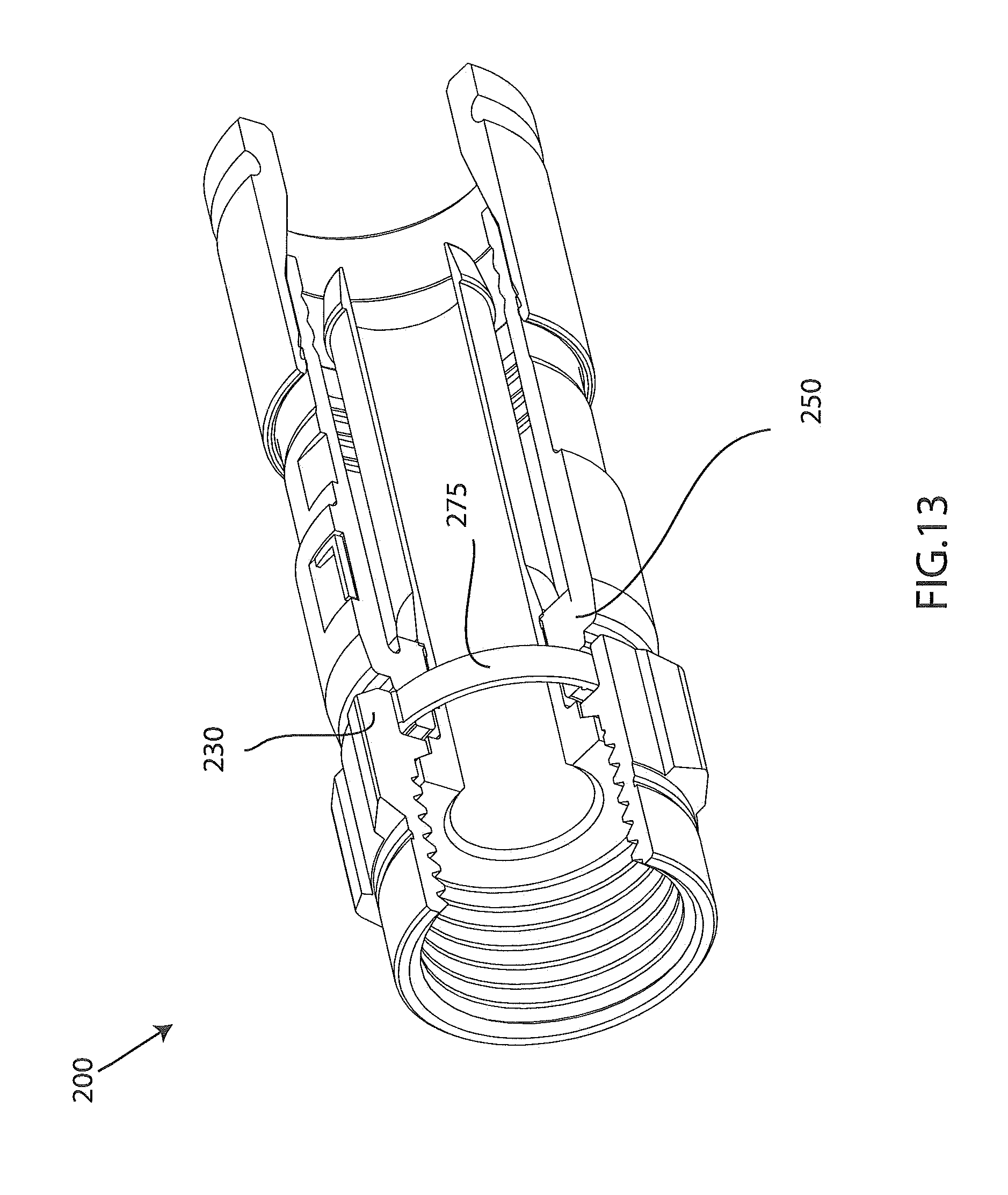
D00013

D00014

XML
uspto.report is an independent third-party trademark research tool that is not affiliated, endorsed, or sponsored by the United States Patent and Trademark Office (USPTO) or any other governmental organization. The information provided by uspto.report is based on publicly available data at the time of writing and is intended for informational purposes only.
While we strive to provide accurate and up-to-date information, we do not guarantee the accuracy, completeness, reliability, or suitability of the information displayed on this site. The use of this site is at your own risk. Any reliance you place on such information is therefore strictly at your own risk.
All official trademark data, including owner information, should be verified by visiting the official USPTO website at www.uspto.gov. This site is not intended to replace professional legal advice and should not be used as a substitute for consulting with a legal professional who is knowledgeable about trademark law.