Bone cutting guide systems and methods
Dayton , et al. January 12, 2
U.S. patent number 10,888,335 [Application Number 16/792,880] was granted by the patent office on 2021-01-12 for bone cutting guide systems and methods. This patent grant is currently assigned to Treace Medical Concepts, Inc.. The grantee listed for this patent is Treace Medical Concepts, Inc.. Invention is credited to F. Barry Bays, Paul Dayton, Joe William Ferguson, Carlos Eduardo Gil, Daniel J. Hatch, Robert D. Santrock, Sean F. Scanlan, W. Bret Smith, John T. Treace.
View All Diagrams
| United States Patent | 10,888,335 |
| Dayton , et al. | January 12, 2021 |
Bone cutting guide systems and methods
Abstract
A method of correcting an alignment between bones of a foot may involve positioning a first cutting slot of a bone cutting guide over a first metatarsal and inserting a first fixation pin through a first fixation aperture of the bone cutting guide and into the first metatarsal. The method may also involve inserting a cutting member through the first cutting slot to remove a portion of the first metatarsal and adjusting an alignment of the first metatarsal relative to a first cuneiform. In some examples, the method further includes positioning a second cutting slot of the bone cutting guide over the first cuneiform and inserting a second fixation pin through a second fixation aperture of bone cutting guide into the first cuneiform. The method can involve inserting a cutting member through the second cutting slot to remove a portion of the first cuneiform and causing the first metatarsal to fuse to the first cuneiform in the moved position.
| Inventors: | Dayton; Paul (Fort Dodge, IA), Santrock; Robert D. (Morgantown, WV), Hatch; Daniel J. (Greeley, CO), Smith; W. Bret (Lexington, SC), Gil; Carlos Eduardo (Jacksonville Beach, FL), Scanlan; Sean F. (Jacksonville, FL), Ferguson; Joe William (Ponte Vedra Beach, FL), Bays; F. Barry (Collierville, TN), Treace; John T. (Ponte Vedra Beach, FL) | ||||||||||
|---|---|---|---|---|---|---|---|---|---|---|---|
| Applicant: |
|
||||||||||
| Assignee: | Treace Medical Concepts, Inc.
(Ponte Vedra, FL) |
||||||||||
| Family ID: | 1000005293848 | ||||||||||
| Appl. No.: | 16/792,880 | ||||||||||
| Filed: | February 17, 2020 |
Prior Publication Data
| Document Identifier | Publication Date | |
|---|---|---|
| US 20200197021 A1 | Jun 25, 2020 | |
Related U.S. Patent Documents
| Application Number | Filing Date | Patent Number | Issue Date | ||
|---|---|---|---|---|---|
| 16593153 | Oct 4, 2019 | 10561426 | |||
| 15603056 | May 23, 2017 | 10603046 | |||
| 14990574 | Jun 27, 2017 | 9687250 | |||
| 62100641 | Jan 7, 2015 | ||||
| Current U.S. Class: | 1/1 |
| Current CPC Class: | A61B 17/1682 (20130101); A61B 17/151 (20130101); A61B 17/15 (20130101) |
| Current International Class: | A61B 17/15 (20060101); A61B 17/16 (20060101) |
References Cited [Referenced By]
U.S. Patent Documents
| 3664022 | May 1972 | Small |
| 4069824 | January 1978 | Weinstock |
| 4159716 | July 1979 | Borchers |
| 4187840 | February 1980 | Watanabe |
| 4335715 | June 1982 | Kirkley |
| 4338927 | July 1982 | Volkov et al. |
| 4349018 | September 1982 | Chambers |
| 4409973 | October 1983 | Neufeld |
| 4440168 | April 1984 | Warren |
| 4501268 | February 1985 | Comparetto |
| 4502474 | March 1985 | Comparetto |
| 4509511 | April 1985 | Neufeld |
| 4565191 | January 1986 | Slocum |
| 4570624 | February 1986 | Wu |
| 4627425 | December 1986 | Reese |
| 4628919 | December 1986 | Clyburn |
| 4632102 | December 1986 | Comparetto |
| 4664102 | May 1987 | Comparetto |
| 4708133 | November 1987 | Comparetto |
| 4736737 | April 1988 | Fargie et al. |
| 4750481 | June 1988 | Reese |
| 4757810 | July 1988 | Reese |
| 4895141 | January 1990 | Koeneman et al. |
| 4952214 | August 1990 | Comparetto |
| 4959066 | September 1990 | Dunn et al. |
| 4978347 | December 1990 | Ilizarov |
| 4988349 | January 1991 | Pennig |
| 4995875 | February 1991 | Coes |
| 5021056 | June 1991 | Hofmann et al. |
| 5035698 | July 1991 | Comparetto |
| 5042983 | August 1991 | Rayhack |
| 5049149 | September 1991 | Schmidt |
| 5053039 | October 1991 | Hofmann et al. |
| 5078719 | January 1992 | Schreiber |
| 5112334 | May 1992 | Alchermes et al. |
| 5147364 | September 1992 | Comparetto |
| 5176685 | January 1993 | Rayhack |
| 5207676 | May 1993 | Canadell et al. |
| 5246444 | September 1993 | Schreiber |
| 5254119 | October 1993 | Schreiber |
| 5312412 | May 1994 | Whipple |
| 5358504 | October 1994 | Paley et al. |
| 5364402 | November 1994 | Mumme et al. |
| 5374271 | December 1994 | Hwang |
| 5413579 | May 1995 | Du Toit |
| 5417694 | May 1995 | Marik et al. |
| 5449360 | September 1995 | Schreiber |
| 5470335 | November 1995 | Du Toit |
| 5490854 | February 1996 | Fisher et al. |
| 5529075 | June 1996 | Clark |
| 5540695 | July 1996 | Levy |
| 5578038 | November 1996 | Slocum |
| 5601565 | February 1997 | Huebner |
| 5613969 | March 1997 | Jenkins, Jr. |
| 5620442 | April 1997 | Bailey et al. |
| 5620448 | April 1997 | Puddu |
| 5643270 | July 1997 | Combs |
| 5667510 | September 1997 | Combs |
| H001706 | January 1998 | Mason |
| 5722978 | March 1998 | Jenkins |
| 5749875 | May 1998 | Puddu |
| 5779709 | July 1998 | Harris et al. |
| 5788695 | August 1998 | Richardson |
| 5803924 | September 1998 | Oni et al. |
| 5810822 | September 1998 | Mortier |
| 5843085 | December 1998 | Graser |
| 5893553 | April 1999 | Pinkous |
| 5911724 | June 1999 | Wehrli |
| 5935128 | August 1999 | Carter et al. |
| 5941877 | August 1999 | Viegas et al. |
| 5951556 | September 1999 | Faccioli et al. |
| 5980526 | November 1999 | Johnson et al. |
| 5984931 | November 1999 | Greenfield |
| 6007535 | December 1999 | Rayhack et al. |
| 6027504 | February 2000 | McGuire |
| 6030391 | February 2000 | Brainard et al. |
| 6162223 | December 2000 | Orsak et al. |
| 6171309 | January 2001 | Huebner |
| 6203545 | March 2001 | Stoffella |
| 6248109 | June 2001 | Stoffella |
| 6391031 | May 2002 | Toomey |
| 6478799 | November 2002 | Williamson |
| 6511481 | January 2003 | Von Hoffmann et al. |
| 6547793 | April 2003 | McGuire |
| 6676662 | January 2004 | Bagga et al. |
| 6719773 | April 2004 | Boucher et al. |
| 6743233 | June 2004 | Baldwin et al. |
| 6755838 | June 2004 | Trnka |
| 6796986 | September 2004 | Duffner |
| 6859661 | February 2005 | Tuke |
| 7018383 | March 2006 | McGuire |
| 7033361 | April 2006 | Collazo |
| 7112204 | September 2006 | Justin et al. |
| 7182766 | February 2007 | Mogul |
| 7241298 | July 2007 | Nemec et al. |
| 7282054 | October 2007 | Steffensmeier et al. |
| 7377924 | May 2008 | Raistrick et al. |
| 7465303 | December 2008 | Riccione et al. |
| 7540874 | June 2009 | Trumble et al. |
| 7572258 | August 2009 | Stiernborg |
| 7641660 | January 2010 | Lakin et al. |
| D610257 | February 2010 | Horton |
| 7686811 | March 2010 | Byrd et al. |
| 7691108 | April 2010 | Lavallee |
| 7763026 | July 2010 | Egger et al. |
| D629900 | December 2010 | Fisher |
| 7967823 | June 2011 | Ammann et al. |
| 7972338 | July 2011 | O'Brien |
| D646389 | October 2011 | Claypool et al. |
| 8057478 | November 2011 | Kuczynski et al. |
| 8062301 | November 2011 | Ammann et al. |
| D651315 | December 2011 | Bertoni et al. |
| D651316 | December 2011 | May et al. |
| 8080010 | December 2011 | Schulz et al. |
| 8083746 | December 2011 | Novak |
| 8123753 | February 2012 | Poncet |
| 8137406 | March 2012 | Novak et al. |
| 8147530 | April 2012 | Strnad et al. |
| 8167918 | May 2012 | Strnad et al. |
| 8172848 | May 2012 | Tomko et al. |
| 8192441 | June 2012 | Collazo |
| 8197487 | June 2012 | Poncet et al. |
| 8231623 | July 2012 | Jordan |
| 8231663 | July 2012 | Kay et al. |
| 8236000 | August 2012 | Ammann et al. |
| 8246561 | August 2012 | Agee et al. |
| D666721 | September 2012 | Wright et al. |
| 8262664 | September 2012 | Justin et al. |
| 8277459 | October 2012 | Sand et al. |
| 8282644 | October 2012 | Edwards |
| 8282645 | October 2012 | Lawrence et al. |
| 8292966 | October 2012 | Morton |
| 8303596 | November 2012 | Plassky et al. |
| 8313492 | November 2012 | Wong et al. |
| 8323289 | December 2012 | Re |
| 8337503 | December 2012 | Lian |
| 8343159 | January 2013 | Bennett |
| 8377105 | February 2013 | Buescher |
| D679395 | April 2013 | Wright et al. |
| 8409209 | April 2013 | Ammann et al. |
| 8435246 | May 2013 | Fisher et al. |
| 8475462 | July 2013 | Thomas et al. |
| 8496662 | July 2013 | Novak et al. |
| 8523870 | September 2013 | Green, II et al. |
| 8529571 | September 2013 | Horan et al. |
| 8540777 | September 2013 | Ammann et al. |
| 8545508 | October 2013 | Collazo |
| D694884 | December 2013 | Mooradian et al. |
| D695402 | December 2013 | Dacosta et al. |
| 8652142 | February 2014 | Geissler |
| 8657820 | February 2014 | Kubiak et al. |
| D701303 | March 2014 | Cook |
| 8672945 | March 2014 | Lavallee et al. |
| 8696716 | April 2014 | Kartalian et al. |
| 8702715 | April 2014 | Ammann et al. |
| D705929 | May 2014 | Frey |
| 8715363 | May 2014 | Ratron et al. |
| 8728084 | May 2014 | Berelsman et al. |
| 8758354 | June 2014 | Habegger et al. |
| 8764760 | July 2014 | Metzger et al. |
| 8764763 | July 2014 | Wong et al. |
| 8771279 | July 2014 | Philippon et al. |
| 8777948 | July 2014 | Bernsteiner |
| 8784427 | July 2014 | Fallin et al. |
| 8784457 | July 2014 | Graham |
| 8795286 | August 2014 | Sand et al. |
| 8801727 | August 2014 | Chan et al. |
| 8808303 | August 2014 | Stemniski et al. |
| 8828012 | September 2014 | May et al. |
| 8858602 | October 2014 | Weiner et al. |
| 8882778 | November 2014 | Ranft |
| 8882816 | November 2014 | Kartalian et al. |
| 8888785 | November 2014 | Ammann et al. |
| D720456 | December 2014 | Dacosta et al. |
| 8900247 | December 2014 | Tseng et al. |
| 8906026 | December 2014 | Ammann et al. |
| 8945132 | February 2015 | Plassky et al. |
| 8998903 | April 2015 | Price et al. |
| 8998904 | April 2015 | Zeetser et al. |
| 9023052 | May 2015 | Lietz et al. |
| 9044250 | June 2015 | Olsen et al. |
| 9060822 | June 2015 | Lewis et al. |
| 9089376 | July 2015 | Medoff et al. |
| 9101421 | August 2015 | Blacklidge |
| 9107715 | August 2015 | Blitz et al. |
| 9113920 | August 2015 | Ammann et al. |
| D740424 | October 2015 | Dacosta et al. |
| D765844 | September 2016 | DaCosta |
| D766434 | September 2016 | DaCosta |
| D766437 | September 2016 | DaCosta |
| D766438 | September 2016 | DaCosta |
| D766439 | September 2016 | DaCosta |
| 9522023 | December 2016 | Haddad et al. |
| 9750538 | September 2017 | Soffiatti et al. |
| 9785747 | October 2017 | Geebelen |
| 10028750 | July 2018 | Rose |
| 10064631 | September 2018 | Dacosta et al. |
| 10159499 | December 2018 | Dacosta et al. |
| 10292713 | May 2019 | Fallin et al. |
| 10327829 | June 2019 | Dacosta et al. |
| 10470779 | November 2019 | Fallin et al. |
| 2002/0099381 | July 2002 | Maroney |
| 2002/0107519 | August 2002 | Dixon et al. |
| 2002/0165552 | November 2002 | Duffner |
| 2002/0198531 | December 2002 | Millard et al. |
| 2004/0010259 | January 2004 | Keller et al. |
| 2004/0039394 | February 2004 | Conti et al. |
| 2004/0097946 | May 2004 | Dietzel et al. |
| 2004/0138669 | July 2004 | Horn |
| 2005/0004676 | January 2005 | Schon et al. |
| 2005/0059978 | March 2005 | Sherry et al. |
| 2005/0070909 | March 2005 | Egger et al. |
| 2005/0075641 | April 2005 | Singhatat et al. |
| 2005/0101961 | May 2005 | Huebner et al. |
| 2005/0149042 | July 2005 | Metzger |
| 2005/0228389 | October 2005 | Stiernborg |
| 2005/0251147 | November 2005 | Novak |
| 2005/0273112 | December 2005 | McNamara |
| 2006/0129163 | June 2006 | McGuire |
| 2006/0206044 | September 2006 | Simon |
| 2006/0217733 | September 2006 | Plassky et al. |
| 2006/0229621 | October 2006 | Cadmus |
| 2006/0241607 | October 2006 | Myerson et al. |
| 2006/0241608 | October 2006 | Myerson et al. |
| 2006/0264961 | November 2006 | Murray-Brown |
| 2007/0010818 | January 2007 | Stone et al. |
| 2007/0123857 | May 2007 | Deffenbaugh et al. |
| 2007/0233138 | October 2007 | Figueroa et al. |
| 2007/0265634 | November 2007 | Weinstein |
| 2007/0276383 | November 2007 | Rayhack |
| 2008/0009863 | January 2008 | Bond et al. |
| 2008/0015603 | January 2008 | Collazo |
| 2008/0039850 | February 2008 | Rowley et al. |
| 2008/0091197 | April 2008 | Coughlin |
| 2008/0140081 | June 2008 | Heavener et al. |
| 2008/0147073 | June 2008 | Ammann et al. |
| 2008/0172054 | July 2008 | Claypool et al. |
| 2008/0195215 | August 2008 | Morton |
| 2008/0208252 | August 2008 | Holmes |
| 2008/0262500 | October 2008 | Collazo |
| 2008/0269908 | October 2008 | Warburton |
| 2008/0288004 | November 2008 | Schendel |
| 2009/0036893 | February 2009 | Kartalian et al. |
| 2009/0036931 | February 2009 | Pech et al. |
| 2009/0054899 | February 2009 | Ammann et al. |
| 2009/0093849 | April 2009 | Grabowski |
| 2009/0105767 | April 2009 | Reiley |
| 2009/0118733 | May 2009 | Orsak et al. |
| 2009/0198244 | August 2009 | Leibel |
| 2009/0198279 | August 2009 | Zhang et al. |
| 2009/0222047 | September 2009 | Graham |
| 2009/0254092 | October 2009 | Albiol |
| 2009/0254126 | October 2009 | Orbay et al. |
| 2009/0287309 | November 2009 | Walch et al. |
| 2010/0069910 | March 2010 | Hasselman |
| 2010/0121334 | May 2010 | Couture et al. |
| 2010/0130981 | May 2010 | Richards |
| 2010/0152782 | June 2010 | Stone et al. |
| 2010/0168799 | July 2010 | Schumer |
| 2010/0185245 | July 2010 | Paul et al. |
| 2010/0249779 | September 2010 | Hotchkiss et al. |
| 2010/0256687 | October 2010 | Neufeld et al. |
| 2010/0318088 | December 2010 | Warne |
| 2010/0324556 | December 2010 | Tyber et al. |
| 2011/0009865 | January 2011 | Orfaly |
| 2011/0093084 | April 2011 | Morton |
| 2011/0118739 | May 2011 | Tyber et al. |
| 2011/0178524 | July 2011 | Lawrence et al. |
| 2011/0245835 | October 2011 | Dodds et al. |
| 2011/0288550 | November 2011 | Orbay et al. |
| 2011/0301648 | December 2011 | Lofthouse et al. |
| 2012/0016426 | January 2012 | Robinson |
| 2012/0065689 | March 2012 | Prasad et al. |
| 2012/0078258 | March 2012 | Lo et al. |
| 2012/0123420 | May 2012 | Honiball |
| 2012/0123484 | May 2012 | Lietz et al. |
| 2012/0130376 | May 2012 | Loring et al. |
| 2012/0130382 | May 2012 | Iannotti et al. |
| 2012/0130383 | May 2012 | Budoff |
| 2012/0184961 | July 2012 | Johannaber |
| 2012/0185056 | July 2012 | Warburton |
| 2012/0191199 | July 2012 | Raemisch |
| 2012/0239045 | September 2012 | Li |
| 2012/0253350 | October 2012 | Anthony et al. |
| 2012/0265301 | October 2012 | Demers et al. |
| 2012/0277745 | November 2012 | Lizee |
| 2012/0330135 | December 2012 | Millahn et al. |
| 2013/0012949 | January 2013 | Fallin et al. |
| 2013/0035694 | February 2013 | Grimm et al. |
| 2013/0085499 | April 2013 | Lian |
| 2013/0096563 | April 2013 | Meade et al. |
| 2013/0131821 | May 2013 | Cachia |
| 2013/0150903 | June 2013 | Vincent |
| 2013/0158556 | June 2013 | Jones et al. |
| 2013/0165936 | June 2013 | Myers |
| 2013/0165938 | June 2013 | Chow et al. |
| 2013/0172942 | July 2013 | Lewis et al. |
| 2013/0184714 | July 2013 | Kaneyama et al. |
| 2013/0190765 | July 2013 | Harris et al. |
| 2013/0190766 | July 2013 | Harris et al. |
| 2013/0204259 | August 2013 | Zajac |
| 2013/0226248 | August 2013 | Hatch et al. |
| 2013/0226252 | August 2013 | Mayer |
| 2013/0231668 | September 2013 | Olsen et al. |
| 2013/0237987 | September 2013 | Graham |
| 2013/0237989 | September 2013 | Bonutti |
| 2013/0267956 | October 2013 | Terrill et al. |
| 2013/0310836 | November 2013 | Raub et al. |
| 2013/0325019 | December 2013 | Thomas et al. |
| 2013/0325076 | December 2013 | Palmer et al. |
| 2013/0331845 | December 2013 | Horan et al. |
| 2013/0338785 | December 2013 | Wong |
| 2014/0005672 | January 2014 | Edwards et al. |
| 2014/0025127 | January 2014 | Richter |
| 2014/0039501 | February 2014 | Schickendantz et al. |
| 2014/0039561 | February 2014 | Weiner et al. |
| 2014/0046387 | February 2014 | Waizenegger |
| 2014/0074099 | March 2014 | Vigneron et al. |
| 2014/0074101 | March 2014 | Collazo |
| 2014/0094861 | April 2014 | Fallin |
| 2014/0094924 | April 2014 | Hacking et al. |
| 2014/0135775 | May 2014 | Maxson et al. |
| 2014/0163563 | June 2014 | Reynolds et al. |
| 2014/0171953 | June 2014 | Gonzalvez et al. |
| 2014/0180342 | June 2014 | Lowery et al. |
| 2014/0188139 | July 2014 | Fallin et al. |
| 2014/0194884 | July 2014 | Martin et al. |
| 2014/0194999 | July 2014 | Orbay et al. |
| 2014/0207144 | July 2014 | Lee et al. |
| 2014/0249537 | September 2014 | Wong et al. |
| 2014/0257308 | September 2014 | Johannaber |
| 2014/0257509 | September 2014 | Dacosta et al. |
| 2014/0276815 | September 2014 | Riccione |
| 2014/0276853 | September 2014 | Long et al. |
| 2014/0277176 | September 2014 | Buchanan et al. |
| 2014/0277214 | September 2014 | Helenbolt et al. |
| 2014/0288562 | September 2014 | Von Zabem et al. |
| 2014/0296995 | October 2014 | Reiley et al. |
| 2014/0303621 | October 2014 | Gerold et al. |
| 2014/0336658 | November 2014 | Luna et al. |
| 2014/0343555 | November 2014 | Russi et al. |
| 2015/0032168 | January 2015 | Orsak et al. |
| 2015/0045801 | February 2015 | Axelson, Jr. et al. |
| 2015/0045839 | February 2015 | Dacosta et al. |
| 2015/0051650 | February 2015 | Verstreken et al. |
| 2015/0057667 | February 2015 | Ammann et al. |
| 2015/0066094 | March 2015 | Prandi et al. |
| 2015/0112446 | April 2015 | Melamed et al. |
| 2015/0119944 | April 2015 | Geldwert |
| 2015/0142064 | May 2015 | Perez et al. |
| 2015/0150608 | June 2015 | Sammarco |
| 2015/0182273 | July 2015 | Stemniski et al. |
| 2015/0223851 | August 2015 | Hill et al. |
| 2015/0245858 | September 2015 | Weiner et al. |
| 2016/0015426 | January 2016 | Dayton |
| 2016/0022315 | January 2016 | Soffiatti et al. |
| 2016/0151165 | June 2016 | Fallin et al. |
| 2016/0175089 | June 2016 | Fallin et al. |
| 2016/0192950 | July 2016 | Dayton et al. |
| 2016/0199076 | July 2016 | Fallin et al. |
| 2016/0213384 | July 2016 | Fallin et al. |
| 2016/0235414 | August 2016 | Hatch et al. |
| 2016/0242791 | August 2016 | Fallin et al. |
| 2016/0256204 | September 2016 | Patel et al. |
| 2016/0324532 | November 2016 | Montoya et al. |
| 2016/0354127 | December 2016 | Lundquist et al. |
| 2017/0042598 | February 2017 | Santrock et al. |
| 2017/0143511 | May 2017 | Cachia |
| 2017/0164989 | June 2017 | Weiner et al. |
| 2018/0344334 | December 2018 | Kim et al. |
| 2009227957 | Jul 2014 | AU | |||
| 2491824 | Sep 2005 | CA | |||
| 2854997 | May 2013 | CA | |||
| 595846 | Sep 2006 | CH | |||
| 2930668 | Aug 2007 | CN | |||
| 201558162 | Aug 2010 | CN | |||
| 201572172 | Sep 2010 | CN | |||
| 201586060 | Sep 2010 | CN | |||
| 201912210 | Aug 2011 | CN | |||
| 101237835 | Nov 2012 | CN | |||
| 202801773 | Mar 2013 | CN | |||
| 103462675 | Dec 2013 | CN | |||
| 103505276 | Jan 2014 | CN | |||
| 203458450 | Mar 2014 | CN | |||
| 102860860 | May 2014 | CN | |||
| 203576647 | May 2014 | CN | |||
| 104490460 | Apr 2015 | CN | |||
| 104510523 | Apr 2015 | CN | |||
| 104523327 | Apr 2015 | CN | |||
| 104546102 | Apr 2015 | CN | |||
| 204379413 | Jun 2015 | CN | |||
| 204410951 | Jun 2015 | CN | |||
| 204428143 | Jul 2015 | CN | |||
| 204428144 | Jul 2015 | CN | |||
| 204428145 | Jul 2015 | CN | |||
| 204446081 | Jul 2015 | CN | |||
| 202006010241 | Mar 2007 | DE | |||
| 102007053058 | Apr 2009 | DE | |||
| 685206 | Sep 2000 | EP | |||
| 1508316 | May 2007 | EP | |||
| 1897509 | Jul 2009 | EP | |||
| 2124772 | Dec 2009 | EP | |||
| 2124832 | Aug 2012 | EP | |||
| 2632349 | Sep 2013 | EP | |||
| 2665428 | Nov 2013 | EP | |||
| 2742878 | Jun 2014 | EP | |||
| 2750617 | Jul 2014 | EP | |||
| 2849684 | Mar 2015 | EP | |||
| 2624764 | Dec 2015 | EP | |||
| 2362616 | Mar 1978 | FR | |||
| 2764183 | Nov 1999 | FR | |||
| 2953120 | Jan 2012 | FR | |||
| 3030221 | Jun 2016 | FR | |||
| 2154143 | Sep 1985 | GB | |||
| 2154144 | Sep 1985 | GB | |||
| 2334214 | Jan 2003 | GB | |||
| 200903719 | Jun 2009 | IN | |||
| 200904479 | May 2010 | IN | |||
| 140/DELNP/2012 | Feb 2013 | IN | |||
| 2004/KOLNP/2013 | Nov 2013 | IN | |||
| 2006158972 | Jun 2006 | JP | |||
| 4134243 | Aug 2008 | JP | |||
| 4162380 | Oct 2008 | JP | |||
| 2011092405 | May 2011 | JP | |||
| 2011523889 | Aug 2011 | JP | |||
| 4796943 | Oct 2011 | JP | |||
| 5466647 | Apr 2014 | JP | |||
| 2014511207 | May 2014 | JP | |||
| 2014521384 | Aug 2014 | JP | |||
| 5628875 | Nov 2014 | JP | |||
| 100904142 | Jun 2009 | KR | |||
| 2098036 | Dec 1997 | RU | |||
| 2195892 | Jan 2003 | RU | |||
| 2320287 | Mar 2008 | RU | |||
| 2321366 | Apr 2008 | RU | |||
| 2321369 | Apr 2008 | RU | |||
| 2346663 | Feb 2009 | RU | |||
| 2412662 | Feb 2011 | RU | |||
| 1333328 | Aug 1987 | SU | |||
| 0166022 | Aug 2001 | WO | |||
| 03075775 | Sep 2003 | WO | |||
| 2004089227 | Oct 2004 | WO | |||
| 2008051064 | May 2008 | WO | |||
| 2009029798 | Mar 2009 | WO | |||
| 2009032101 | Mar 2009 | WO | |||
| 2011037885 | Mar 2011 | WO | |||
| 2012029008 | Mar 2012 | WO | |||
| 2013090392 | Jun 2013 | WO | |||
| 2013134387 | Sep 2013 | WO | |||
| 2013169475 | Nov 2013 | WO | |||
| 2014020561 | Feb 2014 | WO | |||
| 2014022055 | Feb 2014 | WO | |||
| 2014035991 | Mar 2014 | WO | |||
| 2014085882 | Jun 2014 | WO | |||
| 2014147099 | Sep 2014 | WO | |||
| 2014152219 | Sep 2014 | WO | |||
| 2014152535 | Sep 2014 | WO | |||
| 2014177783 | Nov 2014 | WO | |||
| 2014200017 | Dec 2014 | WO | |||
| 2015094409 | Jun 2015 | WO | |||
| 2015105880 | Jul 2015 | WO | |||
| 2015127515 | Sep 2015 | WO | |||
| 2016134160 | Aug 2016 | WO | |||
Other References
|
Rx-Fix Mini Rail External Fixator, Wright Medical Technology, Brochure, Aug. 15, 2014, 2 pages. cited by applicant . Saltzman et al., "Prospective Controlled Trial of STAR Total Ankle Replacement Versus Ankle Fusion: Initial Results," Foot & Ankle International, vol. 30, No. 7, Jul. 2009, pp. 579-596. cited by applicant . Scanlan et al. "Technique Tip: Subtalar Joint Fusion Using a Parallel Guide and Double Screw Fixation," The Journal of Foot and Ankle Surgery, vol. 49, Issue 3, May-Jun. 2010, pp. 305-309, (Abstract Only). cited by applicant . Scranton Jr. et al, "Anatomic Variations in the First Ray: Part I. Anatomic Aspects Related to Bunion Surgery," Clinical Orthopaedics and Related Research, vol. 151, Sep. 1980, pp. 244-255. cited by applicant . Siddiqui et al. "Fixation of Metatarsal Fracture With Bone Plate in a Dromedary Heifer," Open Veterinary Journal, vol. 3, No. 1, 2013, pp. 17-20. cited by applicant . Sidekick Stealth Rearfoot Fixator, Wright Medical Technology, Surgical Technique, Dec. 2, 2013, 20 pages. cited by applicant . Simpson et al., "Computer-Assisted Distraction Ostegogenesis by Ilizarov's Method," International Journal of Medical Robots and Computer Assisted Surgery, vol. 4, No. 4, Dec. 2008, pp. 310-320, (Abstract Only). cited by applicant . Small Bone External Fixation System, Acumed, Surgical Technique, Effective date Sep. 2014, 8 pages. cited by applicant . "Smith & Nephew scores a HAT-TRICK with its entry into the high-growth hammer toe repair market," Smith & Nephew, Jul. 31, 2014, 2 pages. cited by applicant . Stableloc External Fixation System, Acumed, Product Overview, Effective date Sep. 2015, 4 pages. cited by applicant . Stahl et al., "Derotation of Post-Traumatic Femoral Deformities by Closed Intramedullary Sawing," Injury, vol. 37, No. 2, Feb. 2006, pp. 145-151, (Abstract Only). cited by applicant . Talbot et al.," Assessing Sesamoid Subluxation: How Good is the AP Radiograph?," Foot and Ankle International, vol. 19, No. 8, Aug. 1998, pp. 547-554. cited by applicant . TempFix Spanning the Ankle Joint Half Pin and Transfixing Pin Techniques, Biomet Orthopedics, Surgical Technique, 2012, 16 pages. cited by applicant . Tricot et al., "3D-corrective osteotomy using surgical guides for posttraumatic distal humeral deformity," Acta Orthopaedica Belgica, vol. 78, No. 4, 2012, pp. 538-542. cited by applicant . Vitek et al., "Die Behandlung des Hallux rigidus mit Cheilektomie und Akin-Moberg-Osteotomie unter Verwendung einer neuen Schnittlehre und eines neuen Schraubensystems," Orthopadische Praxis, vol. 44, Nov. 2008, pp. 563-566, including English Abstract on p. 564. cited by applicant . Vitek, "Neue Techniken in der Fullchirurgie Das V-tek-System," ABW Wissenschaftsverlag GmbH, 2009, 11 pages, including English Abstract. cited by applicant . Weber et al., "A Simple System for Navigation of Bone Alignment Osteotomies of the Tibia," International Congress Series, vol. 1268, Jan. 2004, pp. 608-613, (Abstract Only). cited by applicant . Weil et al., "Anatomic Plantar Plate Repair Using the Weil Metatarsal Osteotomy Approach," Foot & Ankle Specialist, vol. 4, No. 3, 2011, pp. 145-150. cited by applicant . Wendl et al., "Navigation in der Knieendoprothetik," OP-Journal, vol. 17, 2002, pp. 22-27, including English Abstract. cited by applicant . Whipple et al., "Zimmer Herbert Whipple Bone Screw System: Surgical Techniques for Fixation of Scaphoid and Other Small Bone Fractures," Zimmer, 2003, 59 pages. cited by applicant . Yakacki et al. "Compression Forces of Internal and External Ankle Fixation Devices with Simulated Bone Resorption," Foot and Ankle International, vol. 31, No. 1, Jan. 2010, pp. 76-85, (Abstract Only). cited by applicant . Yasuda et al., "Proximal Supination Osteotomy of the First Metatarsal for Hallux Valgus," Foot and Ankle International, vol. 36, No. 6, Jun. 2015, pp. 696-704. cited by applicant . "Accu-Cut Osteotomy Guide System," BioPro, Brochure, Oct. 2018, 2 pages. cited by applicant . "Acumed Osteotomiesystem Operationstechnik," Acumed, 2014, 19 pages (including 3 pages English translation). cited by applicant . Albano et al., "Biomechanical Study of Transcortical or Transtrabecular Bone Fixation of Patellar Tendon Graft wih Bioabsorbable Pins in ACL Reconstruction in Sheep," Revista Brasileira de Ortopedia (Rev Bras Ortop.) vol. 47, No. 1, 2012, pp. 43-49. cited by applicant . Anderson et al., "Uncemented STAR Total Ankle Prostheses," The Journal of Bone and Joint Surgery, vol. 86(1, Suppl 2), Sep. 2004, pp. 103-111, (Abstract Only). cited by applicant . Blomer, "Knieendoprothetik--Herstellerische Probleme und technologische Entwicklungen," Orthopade, vol. 29, 2000, pp. 688-696, including English Abstract on p. 689. cited by applicant . Bouaicha et al., "Fixation of Maximal Shift Scarf Osteotomy with Inside-Out Plating: Technique Tip," Foot & Ankle International, vol. 32, No. 5, May 2011, pp. 567-569. cited by applicant . Dayton et al., "Is Our Current Paradigm for Evaluation and Management of the Bunion Deformity Flawed? A Discussion of Procedure Philosophy Relative to Anatomy," The Journal of Foot and Ankle Surgery, vol. 54, 2015, pp. 102-111. cited by applicant . Dayton et al., "Observed Changes in Radiographic Measurements of the First Ray after Frontal and Transverse Plane Rotation of the Hallux: Does the Hallux Drive the Metatarsal in a Bunion Deformity?," The Journal of Foot and Ankle Surgery, vol. 53, 2014, pp. 584-587. cited by applicant . Dayton et al., "Relationship of Frontal Plane Rotation of First Metatarsal to Proximal Articular Set Angle and Hallux Alignment in Patients Undergoing Tarsometatarsal Arthrodesis for Hallux Abducto Valgus: A Case Series and Critical Review of the Literature," The Journal of Foot and Ankle Surgery, vol. 52, No. 3, May/Jun. 2013, pp. 348-354. cited by applicant . Dayton et al., "Quantitative Analysis of the Degree of Frontal Rotation Required to Anatomically Align the First Metatarsal Phalangeal Joint During Modified Tarsal-Metatarsal Arthrodesis Without Capsular Balancing," The Journal 3f Foot and Ankle Surgery, 2015, pp. 1-6. cited by applicant . De Geer et al., "A New Measure of Tibial Sesamoid Position in Hallux Valgus in Relation to the Coronal Rotation of the First Metatarsal in CT Scans," Foot and Ankle International, Mar. 26, 2015, 9 pages. cited by applicant . DiDomenico et al., "Correction of Frontal Plane Rotation of Sesamoid Apparatus during the Lapidus Procedure: A Novel Approach," The Journal of Foot and Ankle Surgery, vol. 53, 2014, pp. 248-251. cited by applicant . Dobbe et al. "Patient-Tailored Plate for Bone Fixation and Accurate 3D Positioning in Corrective Osteotomy," Medical and Biological Engineering and Computing, vol. 51, No. 1-2, Feb. 2013, pp. 19-27, (Abstract Only). cited by applicant . EBI Extra Small Rail Fixator, Biomet Trauma, retrieved Dec. 19, 2014, from the Internet: <http://footandanklefixation.com/product/biomet-trauma-ebi-extra-small- -rail-fixator>, 7 pages. cited by applicant . "Futura Forefoot Implant Arthroplasty Products," Tornier, Inc., 2008, 14 pages. cited by applicant . Garthwait, "Accu-Cut System Facilitates Enhanced Precision," Podiatry Today, vol. 18, No. 6, Jun. 2005, 6 pages. cited by applicant . Gonzalez Del Pino et al., "Variable Angle Locking Intercarpal Fusion System for Four-Corner Arthrodesis: Indications and Surgical Technique," Journal of Wrist Surgery, vol. 1, No. 1, Aug. 2012, pp. 73-78. cited by applicant . Gotte, "Entwicklung eines Assistenzrobotersystems fur die Knieendoprothetik," Forschungsberichte, Technische Universitat Munchen, 165, 2002, 11 pages, including partial English Translation. cited by applicant . Gregg et al., "Plantar plate repair and Weil osteotomy for metatarsophalangeal joint instability," Foot and Ankle Surgery, vol. 13, 2007, pp. 116-121. cited by applicant . Grondal et al., "A Guide Plate for Accurate Positioning of First Metatarsophalangeal Joint during Fusion," Operative Orthopadie Und Traumatologie, vol. 16, No. 2, 2004, pp. 167-178 (Abstract Only). cited by applicant . "HAT-TRICK Lesser Toe Repair System," Smith & Nephew, Brochure, Aug. 2014, 12 pages. cited by applicant . "HAT-TRICK Lesser Toe Repair System, Foot and Ankle Technique Guide, Metatarsal Shortening Osteotomy Surgical Technique," Smith & Nephew, 2014, 16 pages. cited by applicant . Hetherington et al., "Evaluation of surgical experience and the use of an osteotomy guide on the apical angle of an Austin osteotomy," The Foot, vol. 18, 2008, pp. 159-164. cited by applicant . Hirao et al., "Computer assisted planning and custom-made surgical guide for malunited pronation deformity after first metatarsophalangeal joint arthrodesis in rheumatoid arthritis: A case report," Computer Aided Surgery, vol. 19, Nos. 1-3, 2014, pp. 13-19. cited by applicant . "Hoffmann II Compact External Fixation System," Stryker, Brochure, Literature No. 5075-1-500, 2006, 12 pages. cited by applicant . "Hoffmann II Micro Lengthener," Stryker, Operative Technique, Literature No. 5075-2-002, 2008, 12 pages. cited by applicant . "Hoffmann Small System External Fixator Orthopedic Instruments," Stryker, retrieved Dec. 19, 2014, from the Internet: <http://www.alibaba.com/product-detail/Stryker-Hoffmann-Small-System-E- xternal-Fixator_1438850129.html>, 3 pages. cited by applicant . Kim et al., "A New Measure of Tibial Sesamoid Position in Hallux Valgus in Relation to the Coronal Rotation of the Firsl Metatarsal in CT Scans," Foot and Ankle International, vol. 36, No. 8, 2015, pp. 944-952. cited by applicant . "Lag Screw Target Bow," Stryker Leibinger GmbH & Co. KG, Germany 2004, 8 pages. cited by applicant . Lieske et al., "Implantation einer Sprunggelenktotalendo-prothese vom Typ Salto 2," Operative Orthopadie und Traumatologie, vol. 26, No. 4, 2014, pp. 401-413, including English Abstract on p. 403. cited by applicant . MAC (Multi Axial Correction) Fixation System, Biomet Trauma, retrieved Dec. 19, 2014, from the Internet: <http://footandanklefixation.com/product/biomet-trauma-mac-multi-axial- -correction-fixation-system>, 7 pages. cited by applicant . Magin, "Computemavigierter Gelenkersatz am Knie mit dem Orthopilot," Operative Orthopadie und Traumatologie, vol. 22, No. 1, 2010, pp. 63-80, including English Abstract on p. 64. cited by applicant . Magin, "Die belastungsstabile Lapidus-Arthrodese bei Hallux-valgus-Deformitat mittels IVP-Plallenfixateur (V-TEK-System)," Operative Orthopadie und Traumatologie, vol. 26, No. 2, 2014, pp. 184-195, including English Abstract on p. 186. cited by applicant . Michelangelo Bunion System, Surgical Technique, Instratek Incorporated, publication date unknown, 4 pages. cited by applicant . Mini Joint Distractor, Arthrex, retrieved Dec. 19, 2014, from the Internet: <http://www.arthrex.com/foot-ankle/mini-joint-distractor/pro- ducts>, 2 pages. cited by applicant . MiniRail System, Small Bone Innovations, Surgical Technique, 2010, 24 pages. cited by applicant . Miyake et al., "Three-Dimensional Corrective Osteotomy for Malunited Diaphyseal Forearm Fractures Using Custom-Made Surgical Guides Based on Computer Simulation," JBJS Essential Surgical Techniques, vol. 2, No. 4, 2012, 11 pages. cited by applicant . Modular Rail System: External Fixator, Smith & Nephew, Surgical Technique, 2013, 44 pages. cited by applicant . Monnich et al., "A Hand Guided Robotic Planning System for Laser Osteotomy in Surgery," World Congress on Medical Physics and Biomedical Engineering vol. 25/6: Surgery, Nimimal Invasive Interventions, Endoscopy and Image Guided Therapy, Sep. 7-12, 2009, pp. 59-62, (Abstract Only). cited by applicant . Moore et al., "Effect of Ankle Flexion Angle on Axial Alignment of Total Ankle Replacement," Foot and Ankle International, vol. 31, No. 12, Dec. 2010, pp. 1093-1098, (Abstract Only). cited by applicant . Mortier et al., "Axial Rotation of the First Metatarsal Head in a Normal Population and Hallux Valgus Patients," Orthopaedics and Traumatology: Surgery and Research, vol. 98, 2012, pp. 677-683. cited by applicant . Nagy et al., "The AO Ulnar Shortening Osteotomy System Indications and Surgical Technique," Journal of Wrist Surgery, vol. 3, No. 2, 2014, pp. 91-97. cited by applicant . NexFix from Nexa Orthopedics, MetaFix I from Merete Medical, Inc. and The BioPro Lower Extremities from BioPro, found in Foot & Ankle International Journal, vol. 28, No. 1, Jan. 2007, 4 pages. cited by applicant . Odenbring et al., "A guide instrument for high tibial osteotomy," Acta Orthopaedica Scandinavica, vol. 60, No. 4, 1989, pp. 449-451. cited by applicant . Okuda et al., "Postoperative Incomplete Reduction of the Sesamoids as a Risk Factor for Recurrence of Hallux Valgus," The Journal of Bone and Joint Surgery, vol. 91-A, No. 1, Jul. 2009, pp. 1637-1645. cited by applicant . Otsuki et al., "Developing a novel custom cutting guide for curved per-acetabular osteotomy," International Orthopaedics (SICOT), vol. 37, 2013, pp. 1033-1038. cited by applicant . "Patient to Patient Precision, Accu-Cut, Osteotomy Guide System," BioPro, Foot & Ankle International Journal, vol. 23, No. 8, Aug. 2002, 2 pages. cited by applicant . Peters et al., "Flexor Hallucis Longus Tendon Laceration as a Complication of Total Ankle Arthroplasty," Foot & Ankle International, vol. 34, No. 1, 2013, pp. 148-149. cited by applicant . "Prophecy Inbone Preoperative Navigation Guides," Wright Medical Technology, Inc., Nov. 2013, 6 pages. cited by applicant . "Rayhack Ulnar Shortening Generation II Low-Profile Locking System Surgical Technique," Wright Medical Technology, Inc., Dec. 2013, 20 pages. cited by applicant . Alvine et al., "Peg and Dowel Fusion of the Proximal Interphalangeal Joint," Foot & Ankle, vol. 1, No. 2, 1980, pp. 90-94. cited by applicant . Bednarz et al., "Modified Lapidus Procedure for the Treatment of Hypermobile Hallux Valgus," Foot & Ankle International, vol. 21, No. 10, Oct. 2000, pp. 816-821. cited by applicant . Carr et al., "Correctional Osteotomy for Metatarsus Primus Varus and Hallux Valgus," The Journal of Bone and Joint Surgery, vol. 50-A, No. 7, Oct. 1968, pp. 1353-1367. cited by applicant . Coetzee et al., "The Lapidus Procedure: A Prospective Cohort Outcome Study," Foot & Ankle International, vol. 25, No. 8, Aug. 2004, pp. 526-531. cited by applicant . Doty et al., "Hallux valgus and hypermobility of the first ray: facts and fiction," International Orthopaedics, vol. 37, 2013, pp. 1655-1660. cited by applicant . Galli et al., "Enhanced Lapidus Arthrodesis: Crossed Screw Technique With Middle Cuneiform Fixation Further Reduces Sagittal Mobility," The Journal of Foot & Ankle Surgery, vol. 54, vol. 3, MaylJun. 2015, published online: Nov. 21, 2014, pp. 437-440. cited by applicant . Lapidus, "The Author's Bunion Operation From 1931 to 1959," Clinical Orthopaedics, vol. 16, 1960, pp. 119-135. cited by applicant . Osher et al., "Accurate Determination of Relative Metatarsal Protrusion with a Small Intermetatarsal Angle: A Novel Simplified Method," The Journal of Foot & Ankle Surgery, vol. 53, No. 5, Sep./Oct. 2014, published online: Jun. 3, 2014, pp. 548-556. cited by applicant . Patel et al., "Modified Lapidus Arthrodesis: Rate of Nonunion in 227 Cases," The Journal of Foot & Ankle Surgery, vol. 43, No. 1, Jan./Feb. 2004, pp. 37-42. cited by applicant . Toth et al., "The Effect of First Ray Shortening in the Development of Metatarsalgia in the Second Through Fourth Rays After Metatarsal Osteotomy," Foot & Ankle International, vol. 28, No. 1, Jan. 2007, pp. 61-63. cited by applicant. |
Primary Examiner: Yang; Andrew
Attorney, Agent or Firm: Fredrikson & Byron, P.A.
Parent Case Text
RELATED APPLICATION
This application is a continuation of U.S. patent application Ser. No. 16/593,153, filed Oct. 4, 2019, which is a continuation of U.S. patent application Ser. No. 15/603,056, filed May 23, 2017, which is a continuation of U.S. patent application Ser. No. 14/990,574, filed Jan. 7, 2016, and issued as U.S. Pat. No. 9,687,250 on Jun. 27, 2017, which in turn claims the benefit of U.S. Provisional Application Ser. No. 62/100,641, filed Jan. 7, 2015. The entire contents of each of these applications are hereby incorporated by reference.
Claims
The invention claimed is:
1. A method of correcting an alignment between bones of a foot, the method comprising: positioning a first cutting slot of a bone cutting guide over a first metatarsal; inserting a first fixation pin through a first fixation aperture of the bone cutting guide and into the first metatarsal, the first fixation aperture being positioned distally of the first cutting slot; inserting a cutting member through the first cutting slot to remove a portion of the first metatarsal; adjusting an alignment of the first metatarsal relative to a first cuneiform separated from the first metatarsal by a joint to establish a moved position of the first metatarsal; positioning a second cutting slot of the bone cutting guide over the first cuneiform; inserting a second fixation pin through a second fixation aperture of bone cutting guide into the first cuneiform, the second fixation aperture being positioned proximally of the second cutting slot; inserting the cutting member through the second cutting slot to remove a portion of the first cuneiform; and causing the first metatarsal to fuse to the first cuneiform in the moved position.
2. The method of claim 1, further comprising: inserting a third fixation pin through a third fixation aperture of the bone cutting guide and into the first metatarsal, the third fixation aperture being positioned distally of the first cutting slot; and inserting a fourth fixation pin through a fourth fixation aperture of bone cutting guide into the first cuneiform, the fourth fixation aperture being positioned proximally of the second cutting slot.
3. The method of claim 1, wherein the second cutting slot is parallel to the first cutting slot, such that inserting the cutting member through the first cutting slot and inserting the cutting member through the second cutting slot results in a cut end of the first metatarsal being parallel to a cut end of the first cuneiform.
4. The method of claim 1, wherein the second cutting slot is angled relative to the first cutting slot, such that inserting the cutting member through the first cutting slot and inserting the cutting member through the second cutting slot results in a cut end of the first metatarsal being angled relative to a cut end of the first cuneiform.
5. The method of claim 1, wherein the cutting member is a saw blade.
6. The method of claim 1, wherein positioning the first cutting slot over the first metatarsal comprises positioning an alignment window defined by the bone cutting guide over the joint.
7. The method of claim 6, further comprising inserting a joint alignment blade through the bone cutting guide and into the joint to align the bone cutting guide.
8. The method of claim 1, wherein inserting the cutting member through the first cutting slot and inserting the cutting member through the second cutting slot comprises inserting the cutting member through the first cutting slot to remove the portion of the first metatarsal prior to inserting the cutting member through the second cutting slot to remove the portion of the first cuneiform.
9. The method of claim 1, wherein inserting the cutting member through the first cutting slot and inserting the cutting member through the second cutting slot comprises inserting the cutting member through the first cutting slot to remove the portion of the metatarsal after inserting the cutting member through the second cutting slot to remove the portion of the cuneiform.
10. The method of claim 1, wherein the bone cutting guide comprises: a first guide surface defining a first plane and a second guide surface defining a second plane, with the first cutting slot being provided between the first plane and the second plane, and a third guide surface defining a third plane and a fourth guide surface defining a fourth plane, with the second cutting slot being provided between the third plane and the fourth plane.
11. The method of claim 1, wherein positioning the first cutting slot over the first metatarsal and positioning the second cutting slot over the first cuneiform comprises positioning the bone cutting guide on a dorsal side of the first metatarsal and the first cuneiform.
12. The method of claim 1, wherein causing the metatarsal to fuse to the cuneiform in the moved position comprises delivering a compound to an area between a cut end of the metatarsal and a cut end of the cuneiform.
13. The method of claim 1, wherein causing the first metatarsal to fuse to the first cuneiform in the moved position comprises applying a bone plate across the joint.
14. The method of claim 13, wherein applying the bone plate comprises applying the bone plate while the metatarsal and cuneiform are held in the moved position by the bone cutting guide.
15. The method of claim 13, wherein the bone plate comprises a first bone plate, and further comprising applying a second bone plate across the joint.
16. The method of claim 15, wherein applying the first bone plate comprises applying the first bone plate on a dorsal side of the first metatarsal and first cuneiform, and applying the second bone plate comprises applying the second bone plate on a medial side of the first metatarsal and the first cuneiform.
17. The method of claim 1, further comprising translating the second cutting slot perpendicularly relative to the first cutting slot to adjust a separation distance between the first cutting slot and the second cutting slot.
18. The method of claim 1, wherein causing the first metatarsal to fuse to the first cuneiform in the moved position comprises applying a compression force between the first metatarsal and the first cuneiform.
19. The method of claim 1, wherein: the bone cutting guide comprises a first guide surface defining a first plane and a second guide surface defining a second plane, with the first cutting slot being provided between the first plane and the second plane, the bone cutting guide comprises a third guide surface defining a third plane and a fourth guide surface defining a fourth plane, with the second cutting slot being provided between the third plane and the fourth plane, and the second cutting slot is angled relative to the first cutting slot, such that inserting the cutting member through the first cutting slot and inserting the cutting member through the second cutting slot results in a cut end of the first metatarsal being angled relative to a cut end of the first cuneiform.
20. The method of claim 19, wherein: the cutting member is a saw blade, and positioning the first cutting slot over the first metatarsal and positioning the second cutting slot over the first cuneiform comprises positioning the bone cutting guide on a dorsal side of the first metatarsal and the first cuneiform.
Description
TECHNICAL FIELD
This disclosure relates generally to devices and methods for positioning and cutting bones.
BACKGROUND
Bones, such as the bones of a foot, may be anatomically misaligned. In certain circumstances, surgical intervention is required to correctly align the bones to reduce patient discomfort and improve patient quality of life.
SUMMARY
In general, this disclosure is directed to bone cutting guide systems and techniques for cutting bones. In some examples, a bone cutting guide includes a main body, or support, that houses a shaft that can translate relative to the main body. The shaft may have a main guide member positioned on the end of the shaft. The main guide member may define opposed guide surfaces configured to receive a cutting member. For example, the cutting member may be inserted between the opposed guide surfaces and bounded within a range of movement by the guide surfaces, causing the cutting member to be directed at a cutting location under the guide surfaces. Additionally or alternatively, the main guide member may define a single cutting surface/plane. The cutting surface/plane may be a surface against which a clinician can position a cutting member and then guide the cutting member along the cutting surface/plane to perform a cutting operation.
The main body of the bone cutting guide can include fixation members, such as fixation pins or apertures, that allow the main body to be fixated on or adjacent a bone to be cut. For example, in use, a clinician may fixate the main body to a bone (e.g., a first metatarsal). Thereafter, the clinician may translate the main guide member having at least one cutting guide surface (e.g., opposed cutting guide surfaces) relative to the fixed main body. The clinician can translate the main guide member by sliding or rotating the shaft housed within the main body, e.g., causing the distal end of the shaft and main guide member carried thereon away from or towards the main body. Once suitably positioned, the clinician may or may not lock the location of the shaft and perform one or more cuts through the guide surfaces of the main guide member.
In some configurations, the bone cutting guide also includes a bridge component that can form a bridge over a section of bone, such as a joint between adjacent bones (e.g., first metatarsal-medial cuneiform joint). For example, the bridge component may have a proximal end that is attachable to the main guide member carried on the shaft attached to the main body and a distal end separated by one or more rails. The proximal end may be insertable between the opposed cutting guide surfaces of the main guide member, e.g., such that the proximal end of the bridge can be inserted between the guide surfaces after performing a cut through the guide surfaces. The distal end of the bridging member can include fixation members, such as fixation pins or apertures, that allow the distal end of the bridging member to be fixated to bone. In one application, the distal end of the bridging member is fixated to a different bone than the bone the main body is fixated to such that the bridging member spans a joint. In such applications, joint spacing may be expanded or contracted by translating the shaft carried by the main body.
In addition to or in lieu of providing a bridging member, in some additional configurations, the bone cutting guide may include a secondary guide member. The secondary guide member can be positioned distally of the main guide member and may also include guide surfaces, such as opposed guide surfaces forming a channel sized and shaped to receive a cutting member. The secondary guide member may facilitate making a second bone cut distal of a location where a first bone cut is made using the main guide member.
In one example, a bone cutting guide is described that includes a support defining an inner cavity and a shaft disposed at least partially within the inner cavity, where the shaft is translatable within the inner cavity relative to the support. The bone cutting guide also includes a main guide member located on an end of the shaft, where the main guide member includes a first guide surface defining a first plane and a second guide surface defining a second plane, and where the first plane is parallel to the second plane.
In another example, a method for cutting bones is described. The method includes fixing a support to a bone and aligning a main guide member to be positioned at a location to be cut. The method further includes making a first cut at the location to be cut by inserting a cutting member through a space defined between a first guide surface of the main guide member and a second guide surface of the main guide member.
The details of one or more examples are set forth in the accompanying drawings and the description below. Other features, objects, and advantages will be apparent from the description and drawings, and from the claims.
BRIEF DESCRIPTION OF THE DRAWINGS
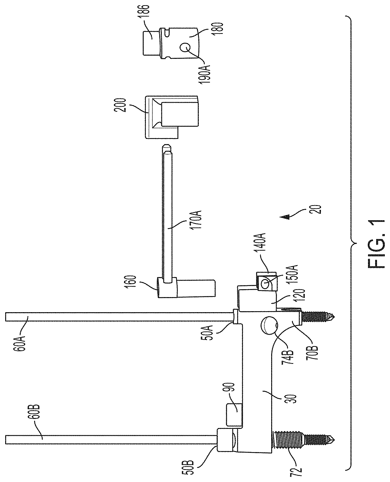
FIG. 1 is a side view of an embodiment of a bone cutting guide, with some components shown in an exploded view.
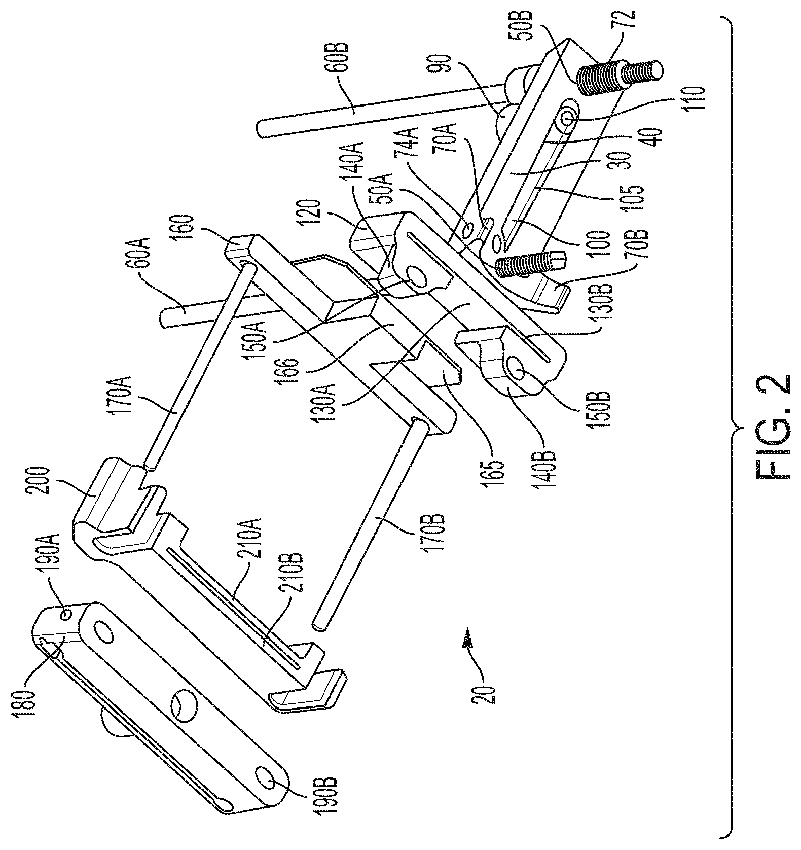
FIG. 2 is a perspective view of the bone cutting guide of FIG. 1.
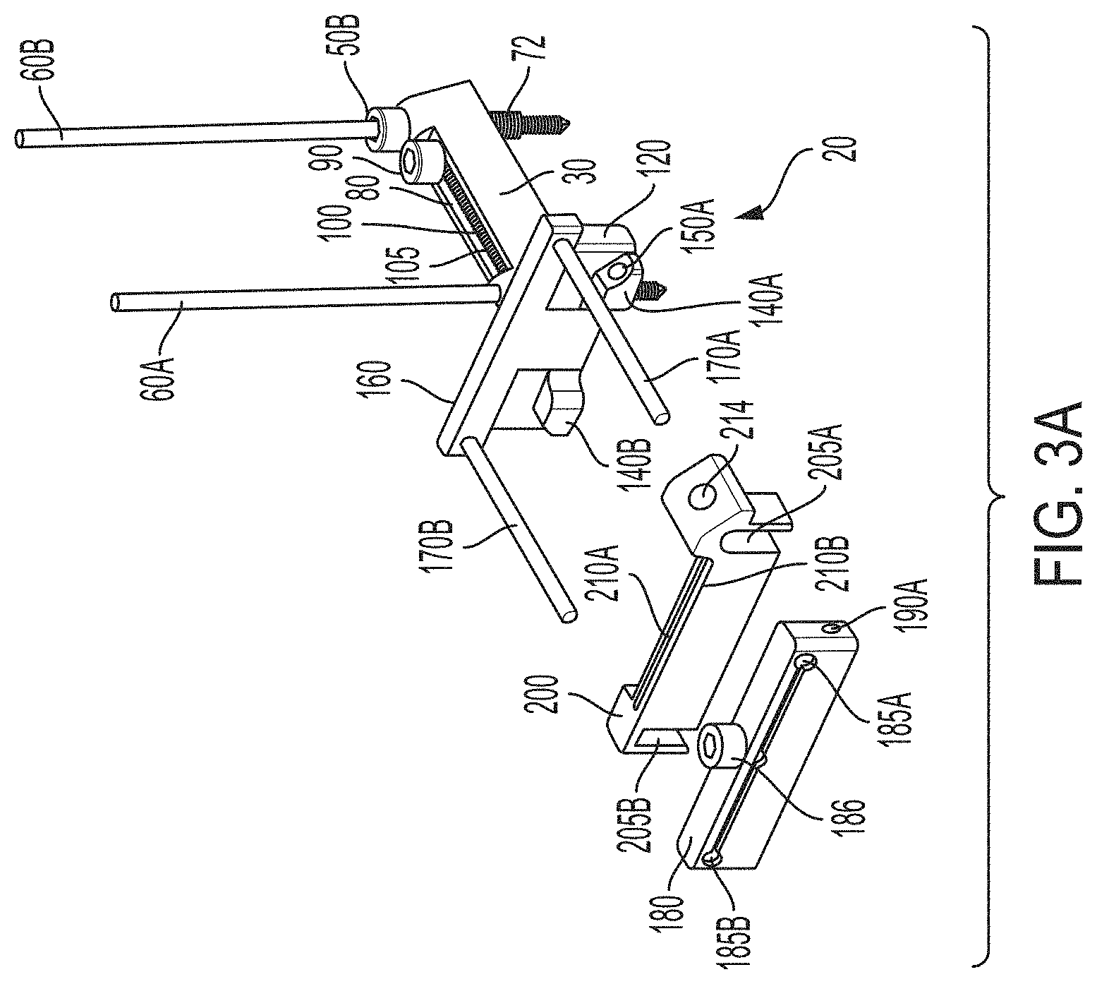
FIG. 3A is a perspective view of the bone cutting guide of FIG. 1 with a bridge component attached to a main guide member.
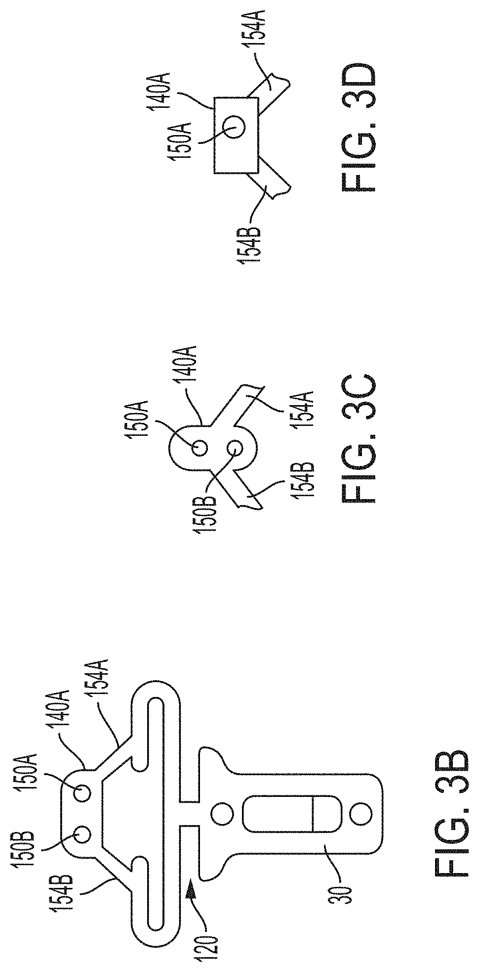
FIGS. 3B-3D are top plan view illustrations of a bone cutting guide with different example connecting blocks.
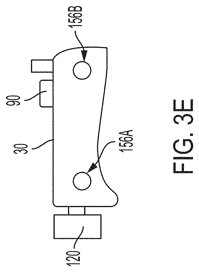
FIG. 3E is a side plan view of a bone cutting guide and an exemplary support.
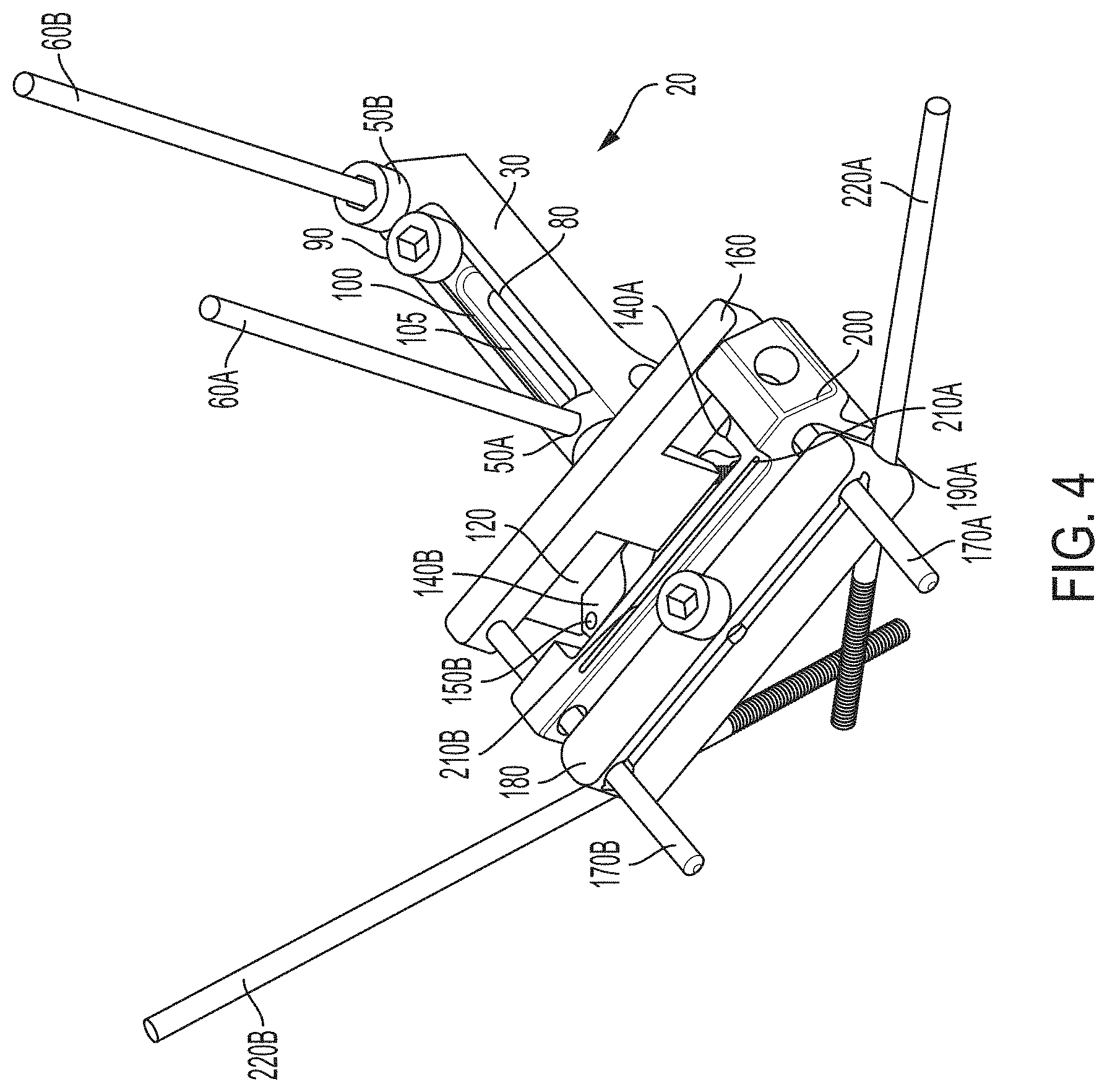
FIG. 4 is a perspective view of the bone cutting guide of FIG. 1 assembled.
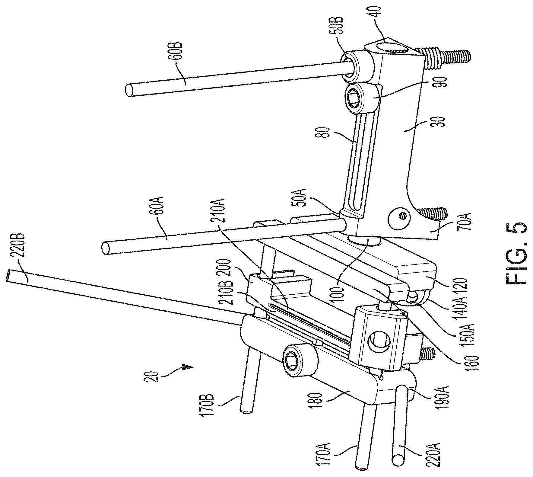
FIG. 5 is another perspective view of the bone cutting guide of FIG. 4.
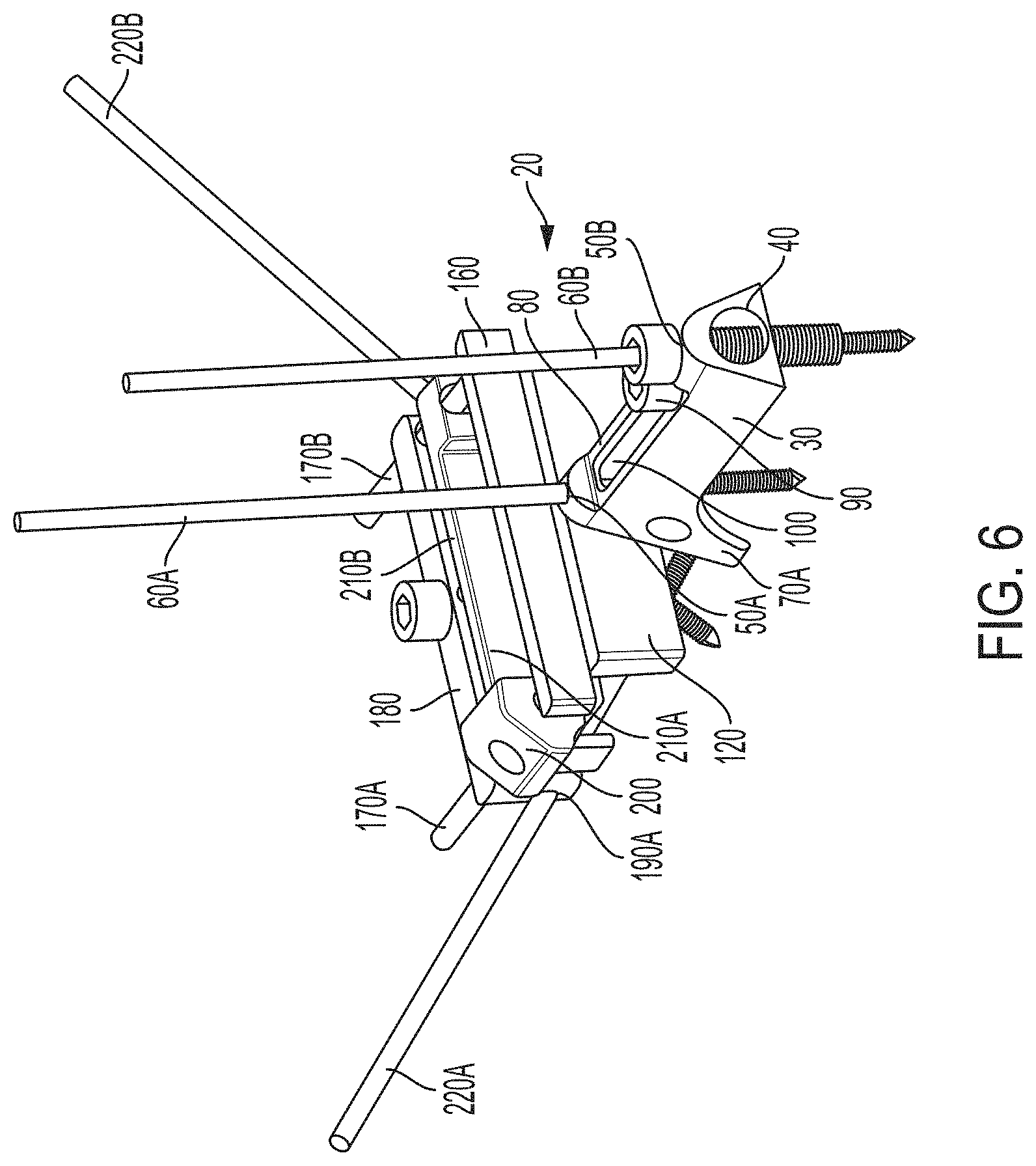
FIG. 6 is a further perspective view of the bone cutting guide of FIG. 4.
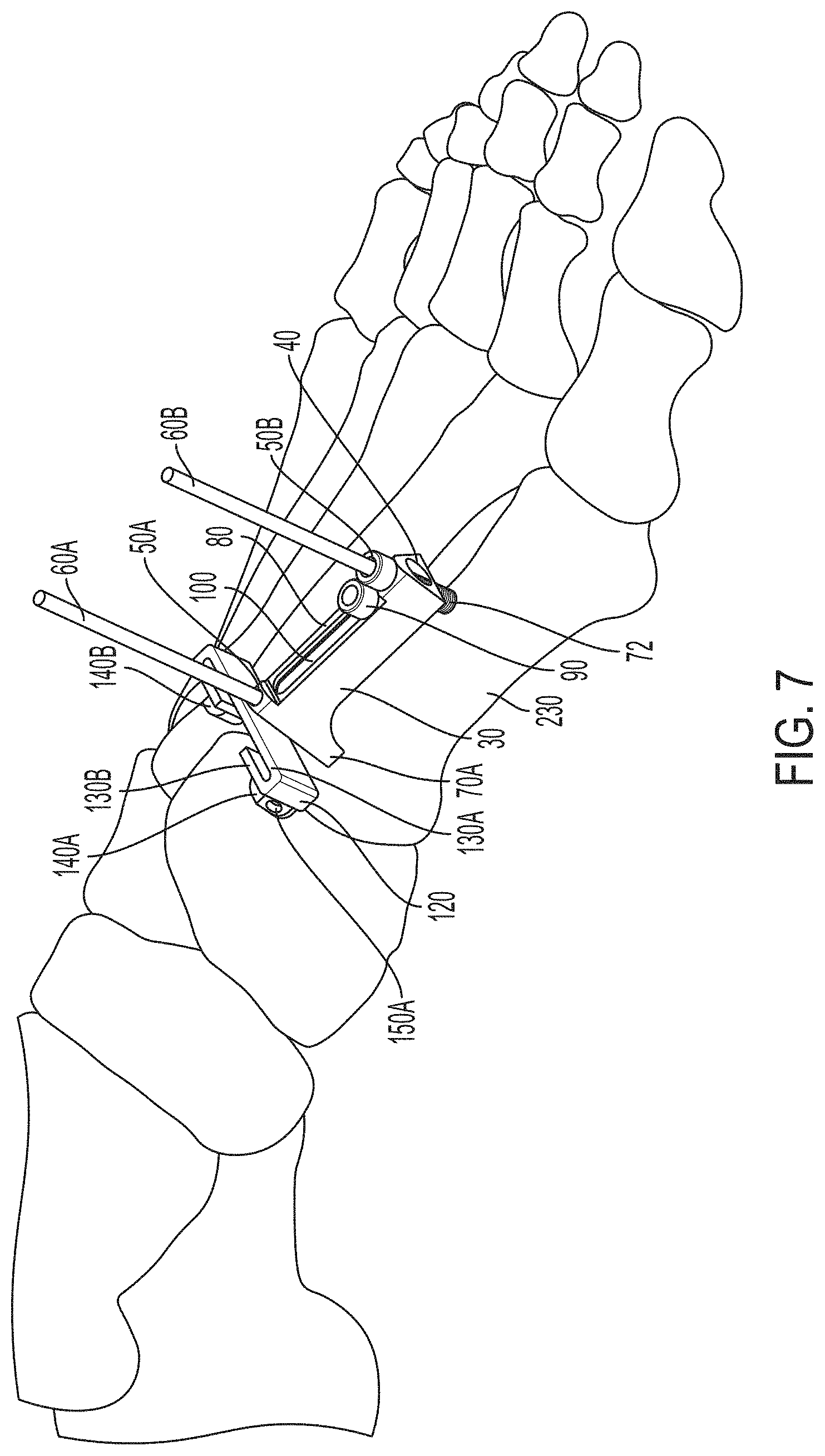
FIG. 7 is a perspective view of a bone cutting guide support fixed to a bone.
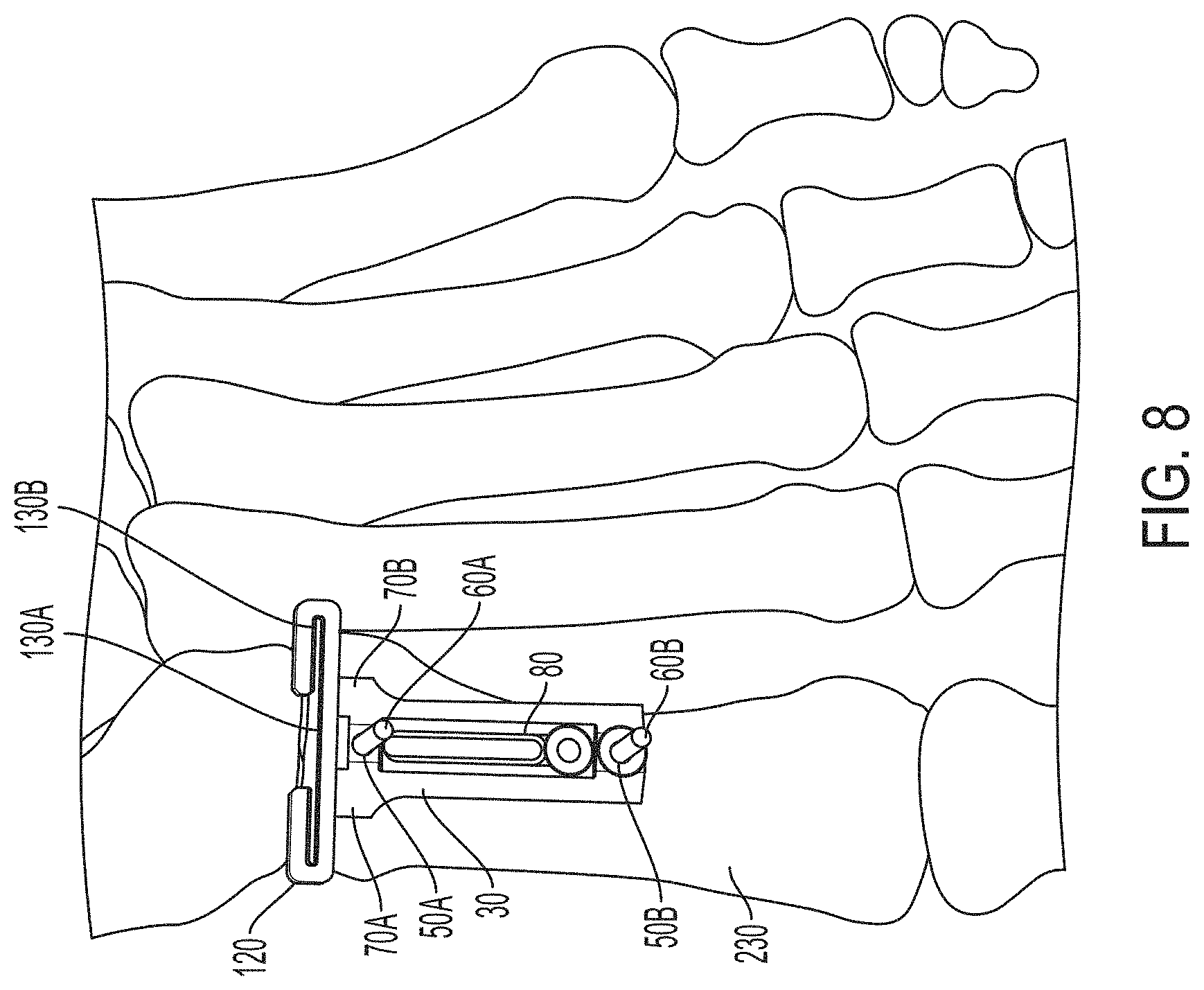
FIG. 8 is a top view of the bone cutting guide support fixed to the bone of FIG. 7.
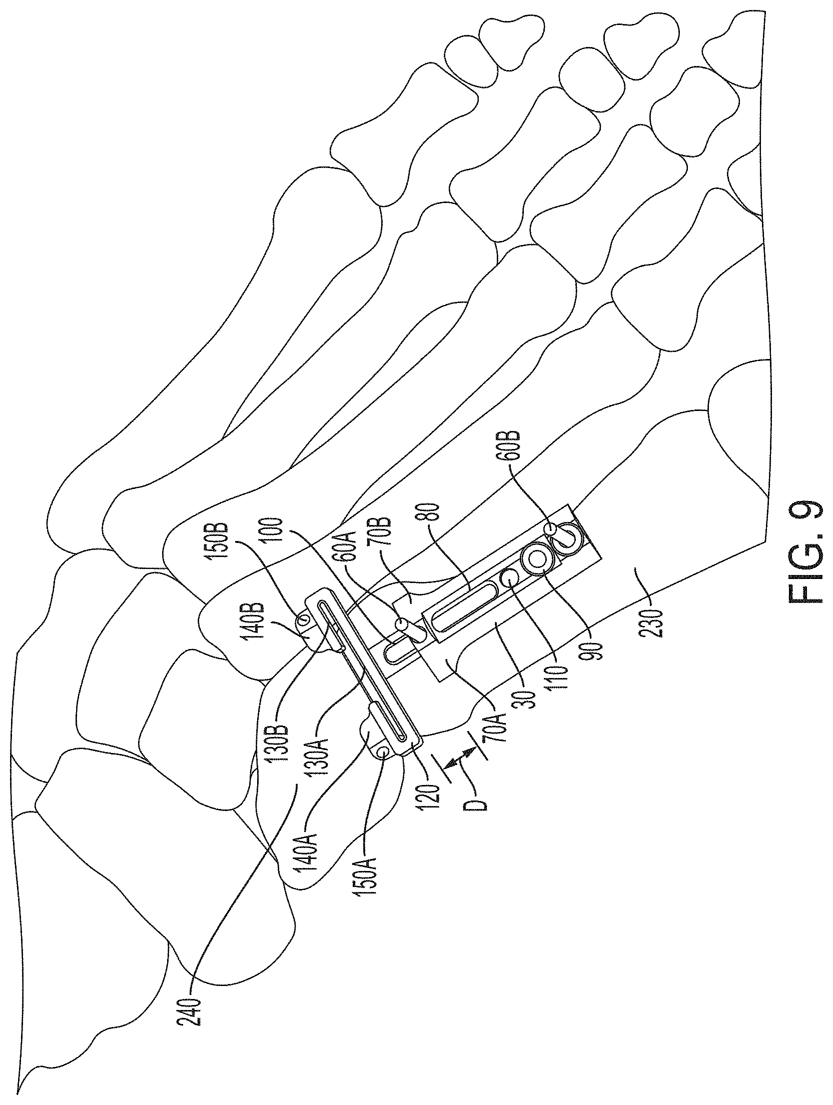
FIG. 9 is a perspective view of the bone cutting guide support fixed to the bone of FIG. 7 with a location of the main guide member adjusted.
FIG. 10 is a perspective view of a bridge component attached to the main guide member of the support of FIG. 7 with a fixation structure attached to the bridge component.
FIG. 11 is a perspective view of the fixation structure pinned across a bone.
FIG. 12 is another perspective view of the pinned fixation structure of FIG. 11.
FIG. 13 is a perspective view of the assembled bone cutting guide fixed to bones.
FIG. 14 is a further perspective view of the assembled bone cutting guide of FIG. 13.
FIG. 15 shows a perspective view of the assembled bone cutting guide of FIG. 13 with a secondary guide member translated along rails of the bridge component.
FIG. 16 is an additional perspective view of the assembled bone cutting guide of FIG. 15.
DETAILED DESCRIPTION
The following detailed description is exemplary in nature and is not intended to limit the scope, applicability, or configuration of the invention in any way. Rather, the following description provides some practical illustrations for implementing exemplary embodiments of the present invention. Examples of constructions, materials, and dimensions are provided for selected elements, and all other elements employ that which is known to those of ordinary skill in the field of the invention. Those skilled in the art will recognize that many of the noted examples have a variety of suitable alternatives.
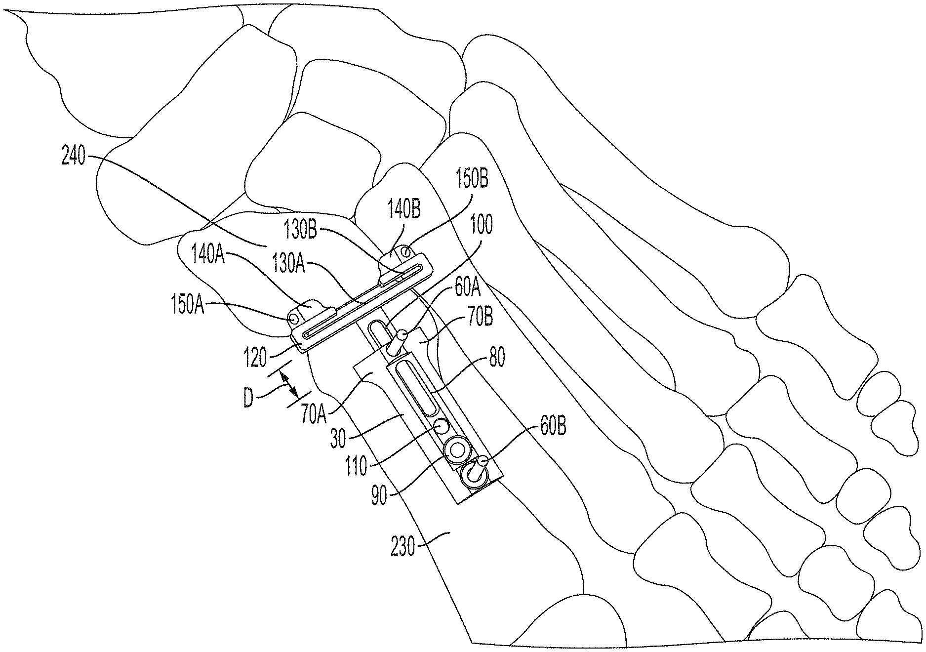
Embodiments of the present invention include a bone cutting guide. In an exemplary application, the bone cutting guide can be useful during a surgical procedure, such as a bone alignment, osteotomy, fusion procedure, and/or other procedures where one or more bones are to be cut. Such a procedure can be performed, for example, on bones (e.g., adjacent bones separated by a joint or different portions of a single bone) in the foot or hand, where bones are relatively smaller compared to bones in other parts of the human anatomy. In one example, a procedure utilizing the bone cutting guide can be performed to correct an alignment between a metatarsal (e.g. a first metatarsal) and a cuneiform (e.g., a first cuneiform), such as a bunion correction. An example of such a procedure is a lapidus procedure. In another example, the procedure can be performed by modifying an alignment of a metatarsal (e.g. a first metatarsal). An example of such a procedure is a basilar metatarsal osteotomy procedure.
FIGS. 1, 2, and 3A show an embodiment of a bone cutting guide 20 with some components of the bone cutting guide 20 shown in an exploded view. FIG. 1 is a side view of the bone cutting guide 20, while FIGS. 2 and 3A are perspective views of the bone cutting guide 20. The bone cutting guide 20 can include a support 30 which defines an inner cavity 40 (FIG. 2). In one embodiment, the support 30 can include a first fixation aperture 50A and a second fixation aperture 50B, each of which can extend through the support 30 and receive fixation pins 60A and 60B, respectively, such that the fixation pins 60A and 60B extend through the support 30 via the fixation apertures 50A and 50B. In the embodiment shown, the fixation pins 60A and 60B have a threaded first end adapted to threadingly engage with a bone, and allow the support 30 to be translated along a longitudinal axis of both pins 60A and 60B. In the illustrated embodiments, the fixation apertures 50A and 50B are located on opposite longitudinal ends of the support 30, but in other embodiments the fixation apertures 50A and 50B can be located at various positions on the support 30.
The support 30 can further include one or more extensions 70A and/or 70B protruding generally radially out from the support 30, which may define a concave surface configured to receive a generally cylindrical bone portion. In the embodiment shown, fixation aperture 50B is provided with an extension member 72 which can be threadingly coupled to the support 30. Such an extension member 72 can be adjusted relative to the support 30 to allow the support to become parallel with a longitudinal axis of a bone, if desired. In such embodiments, the support 30 can rest on a bone via the extensions 70 A/B and extension member 72 in a position generally parallel to the bone. Fixation pin 60B may be received within an internal aperture of the extension member 72. As shown, apertures 74A and B, such as tapered apertures, may be provided proximal to extensions 70 A and B. Such apertures may extend through the support at a skewed angle relative to the longitudinal axis of the support, and may be used to engage a clamping instrument or receive fixation pins.
The support 30 can also include a slot 80 formed on at least a portion of a surface of the support 30. As illustrated in the embodiment of the cutting guide 20 shown in FIG. 3A, the slot 80 can extend in a surface of the support 30 between fixation apertures 50A and 50B. A securing component 90 can be configured to translate along the slot 80 relative to the support 30. For example, the securing component 90 can have a first end with a diameter greater than a diameter of a second opposite end, such that the first end of the securing component 90 is supported by the slot 80 (e.g., the first end has a diameter greater than a radial width of the slot 80) while the second end of the securing component 90 is positioned within the slot 80 (e.g., the second end has a diameter less than a radial width of the slot 80).
The inner cavity 40 of the support 30 can have a shaft 100 positioned at least partially within the inner cavity 40. The shaft 100 can be configured to translate within the inner cavity 40 relative to the support 30, such that an end of the shaft 100 can be made to project out from the inner cavity 40. The shaft 100 may define a slot 105 which may be aligned with the slot 80 defined by the support 30. This slot 105 may receive the pin 60A to reduce interference when the shaft 100 translates. Furthermore, the shaft 100 can include a securing aperture 110 which can be configured to receive at least a portion of the securing component 90. In one embodiment, both the second end of the securing component 90, within the slot 80, and the securing aperture 110 can be threaded to allow the securing component 90 to mate with the securing aperture 110. Such a configuration can allow the shaft 100 to be fixed, such as by compressing a surface of the support 30 that defines the slot 80, and thus prevented from translating within the inner cavity 40, relative to the support 30. In another embodiment, the securing component 90 can be threadingly engaged with the support 30 to act against the shaft 100 to prevent the shaft 100 from traveling with the cavity 40 when desired.
On an end of the shaft 100, a main guide member 120 can be disposed. In some embodiments the main guide member 120 can be integral with the shaft 100, or in other embodiments the main guide member 120 and the shaft 100 can be separate components coupled together. The main guide member 120 can have a first guide surface 130A and a second guide surface 130B, and in some embodiments the main guide member 120 can include blocks 140A and/or 140B. The first and second guide surfaces 130A and 130B can be adjacent surfaces facing one another with a space defined between the first and second guide surfaces 130A and 130B. For example, the first guide surface 130A can be a surface of the main guide member 120 immediately opposite a surface of the main guide member 120 that interfaces with the shaft 100, and the second guide surface 130B can be a surface of the main guide member 120 immediately opposite a surface of the main guide member 120 that includes blocks 140A and 140B.
In the illustrated embodiment, the second guide surface 130B contains a gap, such that the second guide surface 130B is not a single, continuous surface. In other embodiments, the second guide surface 130B can be a single, continuous surface lacking any such gap. The first guide surface 130A defines a first plane, while the second guide surface 130B defines a second plane. As shown, the first guide surface 130A and the second guide surface 130B can be configured such that the first plane is parallel to the second plane, with the space between. In further embodiments (not illustrated), the guide surfaces 130A and 130B can be configured such that the first and/or second planes are skewed.
As previously noted, a surface of the main guide member 120 can include one or more blocks 140A and 140B, either integral with the main guide member 120 or as separate components attached to the main guide member 120. As shown, the blocks 140A and 140B can be on a surface on a side of the main guide member 120 furthest from the interface with the shaft 100. In other applications, the blocks 140A and 140B can be located at various other positions on the main guide member 120. The blocks 140A and 140B can include fixation apertures 150A and 150B respectively. The fixation apertures 150A and 150B extend through the blocks 140A and 140B and provide a location for configuring additional fixation pins to, for example, position a bone or bones.
As shown in FIGS. 3B-3D, the main guide member 120 and at least one block 140A can assume other configurations. In FIG. 3B, the block 140A includes fixation apertures 150A and B and is spaced from the guide surfaces a distance via connecting flanges 154A and 154B. In the embodiment of FIG. 3B, the fixation apertures 150A and B are positioned in a line substantially parallel to the guide surfaces. In FIG. 3C, the orientation of the fixation apertures 150A and B is substantially perpendicular to the guide surfaces. In FIG. 3D, only one fixation aperture 150A is provided.
Another embodiment of a support 30 is depicted in FIG. 3E. In FIG. 3E, the support 30 has at least one (e.g., two) fixation aperture 156A and 156B formed in its side to receive fixation pins. Such apertures can also be included on the opposite side of the support (not shown). In some embodiments, the fixation apertures 156A and 156B can be positioned in a line substantially parallel with a longitudinal axis of the support, and can extend in a direction substantially perpendicular to the longitudinal axis of the support. In certain embodiments, the apertures extend at an angle, such as about 20 degrees, from vertical. In such embodiments, the support 30 can be placed on a dorsal surface and after a first cut or cuts, can be rotated about a pin extending though one of the fixation apertures 156A and 156B to rotate the support relative to the bone and first cut or cuts. The support can then be further pinned to the bone and an additional cut or cuts can be made at a desired angle relative to the first cut or cuts.
In addition to the support 30, the bone cutting guide 20 can include a bridge component 160. As shown in FIG. 3A, the bridge component 160 can attach to the main guide member 120. In particular, in some applications of the bone cutting guide 20, the bridge component 160 can have a geometry that allows the bridge component 160 to attach to the main guide member 120 between the first and second guide surfaces 130A and 130B through an interference fit. Optionally, a locking mechanism can be provided to lock the bridge component to the main guide member, such as a locking tab, screw, pin, cam, etc. For example, the bridge component 160 may have a planar member 165 (shown in FIG. 2) that is received within the gap between the surfaces 130A and 130B and an extending block 166 (shown in FIG. 2) adapted to extend into the surface gap of 130B. In other applications, the bridge component 160 can be coupled to the main guide member 120 by any attachment mechanism, such as screws or clamps. The bridge component 160 can include rails 170A and 170B, each extending out from the bridge component 160 in a same general direction. In other embodiments, the rails 170A and 170B can extend out from the bridge component 160 at different angles.
The bone cutting guide 20 can also include in some embodiments a fixating structure 180. The fixating structure 180 can be supported on the rails 170A and 170B. For example, the fixating structure 180 can include apertures 185A and 185B to receive the rails 170A and 170B, respectively. The fixating structure 180 can be secured to the rails 170A and 170B, such that the fixating structure 180 is obstructed from translating along the rails 170A and 170B, by turning or otherwise actuating an actuator 186 of the fixating structure 180, which moves a lock (not shown) to act against the rails. Furthermore, the fixating structure 180 can also include one or more fixation apertures 190A and/or 190B. Fixation apertures 190A and 190B extend through fixating structure 180 and can be located on opposite ends of the fixating structure 180, at a skewed angle, and serve to receive fixation pins or other means for stabilizing the bone cutting guide 20 across a targeted anatomy and/or positioning a bone or bones.
Additionally, the bone cutting guide 20 can have a secondary guide member 200. The secondary guide member 200 can be supported on the rails 170A and 170B. For example, the secondary guide member 200 may include slots 205A and 205B to receive the rails 170A and 170B such that the secondary guide member 200 is supported thereon. The secondary guide member 200 can also have a third guide surface 210A and a fourth guide surface 210B. The third and fourth guide surfaces 210A and 210B can be adjacent surfaces facing one another with a space defined between the third and fourth guide surfaces 210A and 210B. In the illustrated embodiments, third and fourth guide surfaces 210A and 210B are single, continuous surfaces that do not include a gap, but in other embodiments third and/or fourth guide surfaces 210A and 210B can include a gap. The third guide surface 210A defines a third plane, while the fourth guide surface 210B defines a fourth plane. As shown, the third guide surface 210A and fourth guide surface 210B can be configured such that the third plane is parallel to the fourth plane, with the space between. In further embodiments (not illustrated), the guide surfaces 210A and 210B can be configured such that the third and/or fourth planes are skewed. Further, the third and/or fourth guide surfaces may be parallel to or skewed with respect to the first and/or second guide surfaces, such that the cutting guide can be adapted to make parallel cuts or angular cuts or cut shapes (e.g. a chevron shape). In some embodiments, the secondary guide member 200 can be locked to the rails 170A and/or 170B with a locking screw, cam, pin, etc. In the embodiment shown in FIG. 3A, an aperture 214 is provided to receive a locking mechanism and/or an accessory, such as a handle.
FIGS. 4-6 illustrate perspective views of the embodiment of the bone cutting guide 20, described with respect to FIGS. 1-3, as assembled. In the embodiment illustrated in FIGS. 4-6, the bridge component 160 is attached to the main guide member 120 and both the fixating structure 180 and secondary guide member 200 are supported along the rails 170A and 170B of the bridge component. In one application, the secondary guide member 200 can be supported on the rails 170A and 170B at a location along the rails 170A and 170B between the fixating structure 180 and the main guide member 120. Additionally shown in FIGS. 4-6 are fixation pins 220A and 220B received within fixation apertures 190A and 190B such that the fixation pins 220A and 220B extend through the fixating structure 180. In some applications of the bone cutting guide 20, it may be desirable to provide the fixation pins 220A and 220B at an angle other than 90 degrees relative to a top surface of the fixating structure 180 by configuring the fixation apertures 190A and 190B to extend through the fixating structure 180 at a skewed angle to guide the fixating pins 220A and 220B. Fixation pins 220A and 220B can be used, for example, for stabilizing the bone cutting guide 20 across a targeted anatomy and/or positioning a bone or bones.
Embodiments of the bone cutting guide 20 can be useful in operation for temporarily positioning a bone or bones and guiding a cutting of a bone or bones at a targeted anatomy. Bone cutting can be useful, for instance, to facilitate contact between leading edges of adjacent bones, separated by a joint, or different portions of a single bone, separated by a fracture, such as in a bone alignment and/or fusion procedure. As such, embodiments of the present invention include methods for temporarily fixing an orientation of a bone or bones, such as during a surgical procedure, and guiding cutting at desired bone locations. In the embodiments described, cuts are made to bone with respect to the cutting guide, and the bones can be positioned for an additional surgical step, such as bone plating, after the cuts have been made.
FIGS. 7-16 illustrate steps of an embodiment of a method for temporarily positioning and cutting a bone or bones using the bone cutting guide 20. Specifically, FIGS. 7 and 8 show a perspective and top view, respectively, of the support 30 fixed to a bone 230 (e.g. a first metatarsal). The support 30 is placed on the bone 230. For embodiments of the bone cutting guide 20 that include the extensions 70A and 70B, the extensions 70A and 70B can be used to at least partially straddle the bone 230 and consequently provide both greater stability to the support 30 on the bone 230 and anatomical alignment of the support 30 on a longitudinal axis of the bone 230 (e.g., the slot 80 is generally parallel to the longitudinal axis of the bone 230). Extension member 72 can be adjusted to a desired distance from support 30. Further, in some embodiments it can be desirable to align and fix the support 30 along the longitudinal axis of the bone 230 using the fixation pins 60A and 60B. The pin 60A can be inserted through the fixation aperture 50A such that an end of the pin 60A protrudes out from the fixation aperture 50A adjacent the bone 230. The pin 60A can then be fixed to the bone 230. Similarly, the pin 60B can be inserted through fixation aperture 50B and fixed on an end to the bone 230. In this manner, the support 30 can be fixed in place to and aligned along the longitudinal axis of the bone 230.
In addition to fixing the support 30 to the bone 230, the main guide member 120 can be aligned such that the main guide member 120 is positioned at a location where a bone (e.g., the bone 230) is to be cut. In one embodiment, the main guide member 120 can be positioned at the location where a bone is to be cut by appropriately positioning and fixing the support 30, e.g., such that the support 30 is fixed to the bone 230 at a location along bone 230 that results in the main guide member 120 being positioned at the location where a bone is to be cut. In some embodiments, a joint alignment blade (not shown) is inserted though the main guide member and into a joint space to help align the main guide member in a desired position. Further, in certain embodiments, a provisional fixation pin (not shown) can be inserted through a bone of interest and into an adjacent bone (e.g., though a first metatarsal and into a second metatarsal) to provide additional stability during the procedure.
In some applications, a location of the main guide member 120 relative to the longitudinal axis of the bone 230 can be adjusted without necessitating movement of the support 30. To accomplish this, the shaft 100 at least partially within the inner cavity 40 can be translated relative to the support 30 as shown in the perspective view of FIG. 9. As shown, the main guide member 120 has been translated along the longitudinal axis of the bone 230 a distance D as a result of the shaft 100 being moved the same distance D. Once the main guide member 120 is positioned at the location to be cut, the securing component 90 can be translated along the slot 80 such that the securing component 90 is aligned with securing aperture 110. The securing component 90 can then be fixed within the securing aperture 110 such that the shaft 100 is fixed relative to the support 30.
After the main guide member 120 has been positioned at the location to be cut, a cutting member (e.g. a saw blade) can be inserted through the space defined between the first guide surface 130A and the second guide surface 130B to cut, for example, the bone 230. The guide surfaces 130A and 130B can serve to direct the cutting member to the location of the bone 230 to be cut, which in many applications can be a precise location. The break or window defined in the second guide surface 130B can assist in visualizing the portion of the bone 230 being cut.
In some embodiments, the main guide member 120 can be used to make additional cuts. In such embodiments, the securing component 90 can be loosened and the shaft 100 can be translated within the cavity to a desired position. The securing component 90 can be then be fixed within the securing aperture so the shaft is again fixed relative to the support 30. In some embodiments, fixation pins may be inserted through fixation aperture 150A and/or 150B and into the bone 230 to further stabilize the main guide member. After the main guide member 120 has been repositioned at the location to be cut, a cutting member (e.g. a saw blade) can be inserted through the space defined between the first guide surface 130A and the second guide surface 130B to cut, for example, the bone 240. The guide surfaces 130A and 130B can serve to direct the cutting member to the location of the bone 240 to be cut.
In some applications, it may be desirable to provide additional, temporary fixation of the bone 230 to allow for more accurate cutting. As best seen again in FIG. 9, blocks 140A and 140B can provide a means for additionally positioning the bone 230. Fixation pins can be inserted through the fixation aperture 150A and/or 150B and into the bone 230 to temporarily position the bone 230 and/or adjacent bone 240 for cutting. In other applications, blocks 140A and 140B may not be necessary.
As shown in the perspective view of FIG. 10, once the bone 230 has been cut the bridge component 160 can optionally be attached to the main guide member 120. In one embodiment, the bridge component 160 can have a geometry that allows the bridge component 160 to attach to the main guide member 120 between the first and second guide surfaces 130A and 130B through an interference fit, while in other embodiments the bridge component 160 can attach to the main guide member 120 by other attachment means. The rails 170A and 170B of the bridge component 160 can be arranged such that the rails 170A and 170B extend out from the bridge component 160 on a side of the bridge component 160 opposite the support 30. The rails 170A and 170B can serve to support additional components of the bone cutting guide 20.
One such component of the bone cutting guide 20 that can be supported on the rails 170A and 170B is the fixating structure 180. FIG. 10 shows the fixating structure 180 attached to the rails 170A and 170B. In one embodiment, the fixating structure 180 can have holes or slots for receiving the rails 170A and 170B such that the fixating structure 180 can translate along the rails 170A and 170B to a desired position. The fixating structure 180, for example, can also be secured to the rails 170A and 170B in a manner that prevents translation of the fixating structure 180 when desired by actuating the actuator 186.
FIGS. 11 and 12 illustrate perspective views of the fixating structure 180 with the fixation pins 220A and 220B received through the fixation apertures 190A and 190B (190 B is shown in, e.g., FIG. 2). Fixation apertures 190A and 190B can be on opposite ends of the fixating structure 180 as shown. Fixation pins 220A and 220B can be fixed to a bone 240 (e.g. a first cuneiform as illustrated) to provide stability for the bone cutting guide 20 and/or to position the bone 240. After the pins 220A and 220B are set, the fixating structure 180 can be translated with respect to the rails 170A and 170B and the support 30 to a desired position to compress or expand the space between the bones 230 and 240 as needed. The position of the bones can be locked by securing the fixating structure 180 against the rails 170A and 170B. In other embodiments, such compression or expansion can be achieved by moving the shaft 100 relative to the support 30 and reengaging the securing component 90 at the new desired position.
FIGS. 13 and 14 show perspective views of the bone cutting guide 20 assembled to include the secondary guide member 200. The secondary guide member 200 can be supported on the rails 170A and 170B. In one embodiment, the slots 205A and 205B of the secondary guide member 200 can receive the rails 170A and 170B such that the secondary guide member 200 can translate along the rails 170A and 170B to a desired position. As illustrated, the secondary guide member 200 can be located along the rails 170A and 170B between the fixating structure 180 and the bridge component 160.
The secondary guide member 200 can be positioned at a location where a second bone cut is to be made. A cutting member (e.g. a saw blade) can be inserted through the space defined between the third and fourth guide surfaces 210A and 210B to cut, for example, the bone 240. The guide surfaces 210A and 210B can serve to direct the cutting member to the location of the bone 240 to be cut, which in many applications can be a precise location. As illustrated, the cut made using the secondary guide member 200 (e.g. to bone 240) will be a cut that is generally parallel to the cut made using the main guide member 120. However, in other embodiments components of the bone cutting guide 20 (e.g. rails 170A and 170B) can be configured such that the cut made using the secondary guide member 200 is an angular cut (i.e. not parallel) relative to the cut made using the main guide member 120.
FIGS. 15 and 16 illustrate the bone cutting guide 20 as described previously, with the secondary guide member 200 translated along the rails 170A and 170B. The secondary guide member 200 can be translated along the rails 170A and 170B to precisely locate the secondary guide member 200 at the location to be cut (e.g. on bone 240). In the embodiment illustrated, the secondary guide member 200 can be shaped such that a portion of the secondary guide member 200 can overlap, or sit on top of, the bridge component 160. Such a configuration can be useful, for example, where the second cut made using the secondary guide member 200 is desired to be close to the first cut made using the main guide member 120 (e.g. portions of bones 230 and 240 interfacing at a joint).
When the bone 230 and/or bone 240 have been cut and positioned as desired, the bone cutting guide 20 can be removed. In some embodiments, the cutting guide 20 is temporarily removed from the fixation pins and cut bone is removed from the area. In certain embodiments, an autograft or other compound is delivered to the area of the bone cuts. Optionally, the guide may then be reset on the bones over the fixation pins and the shaft 100 can be translated within the cavity to adjust the relative position of the bones (e.g., to compress them together). The securing component 90 can be then be fixed within the securing aperture so the shaft is again fixed relative to the support 30. A bone plate may optionally be applied across the joint while the bones are held in the longitudinally fixed position by the cutting guide. After the plate is applied, the bone cutting guide and the fixation pins may be removed. Removing the bone cutting guide 20 can include removing all fixation pins and the support, and, in some embodiments, can include removing the bridge component, along with the fixation structure and secondary guide member 200. In certain embodiments, a second bone plate may optionally be applied across the joint. In a specific embodiment, the two bone plates are applied about 90 degrees from each other around the circumferences of the bones (e.g., at a dorsal side and a medial side).
Thus, embodiments of the invention are disclosed. Although the present invention has been described with reference to certain disclosed embodiments, the disclosed embodiments are presented for purposes of illustration, and not limitation, and other embodiments of the invention are possible. One skilled in the art will appreciate that various changes, adaptations, and modifications may be made without departing from the spirit of the invention.
* * * * *
References
-
footandanklefixation.com/product/biomet-trauma-ebi-extra-small-rail-fixator
-
alibaba.com/product-detail/Stryker-Hoffmann-Small-System-External-Fixator_1438850129.html
-
-
arthrex.com/foot-ankle/mini-joint-distractor/products
D00000
D00001
D00002
D00003
D00004
D00005
D00006
D00007
D00008
D00009
D00010
D00011
D00012
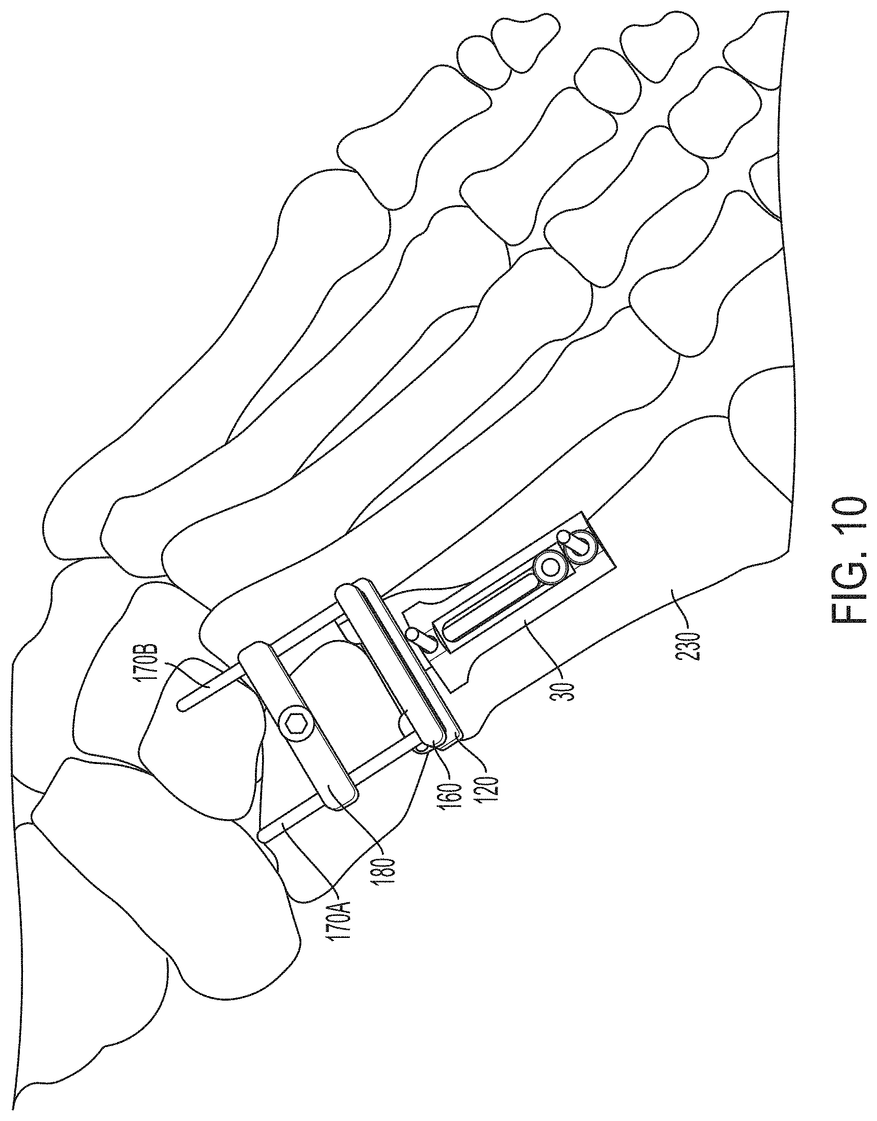
D00013
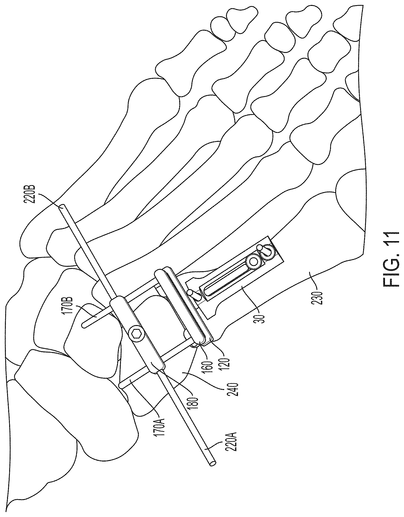
D00014

D00015
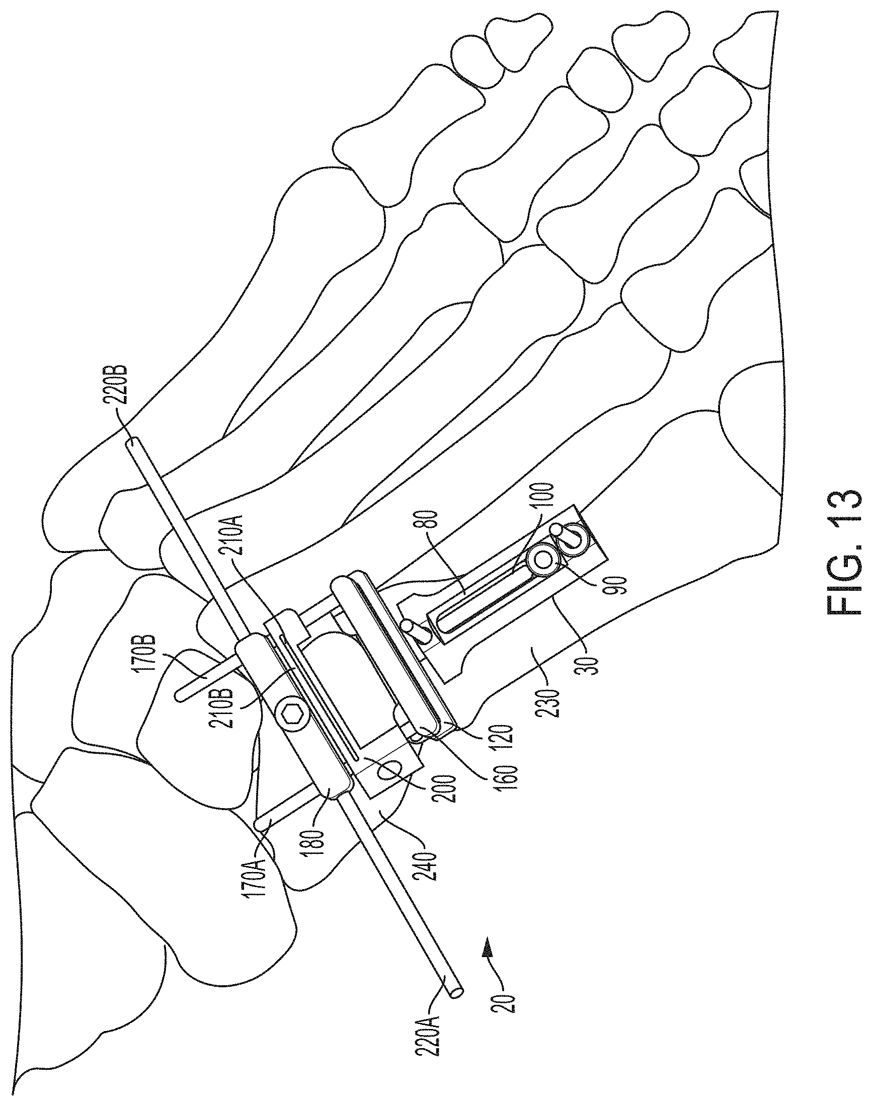
D00016
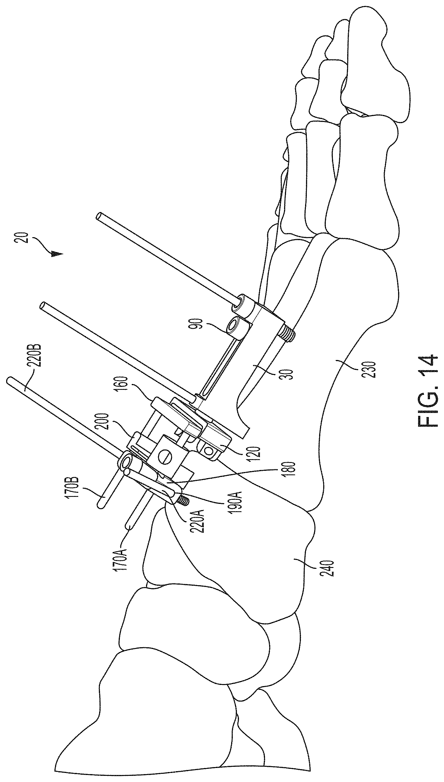
D00017
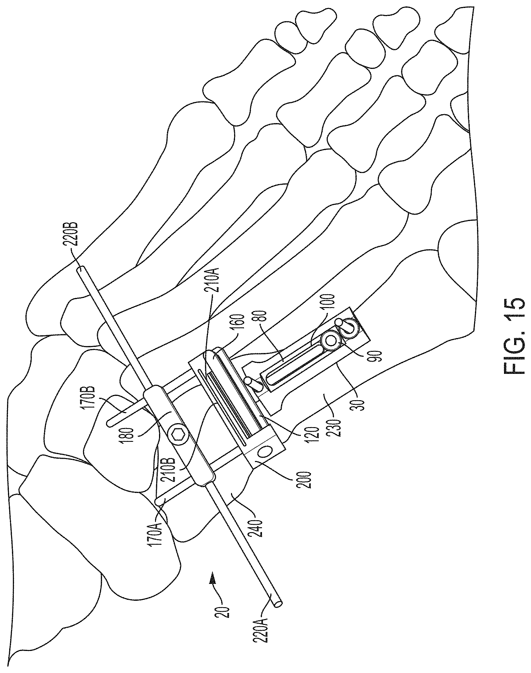
D00018
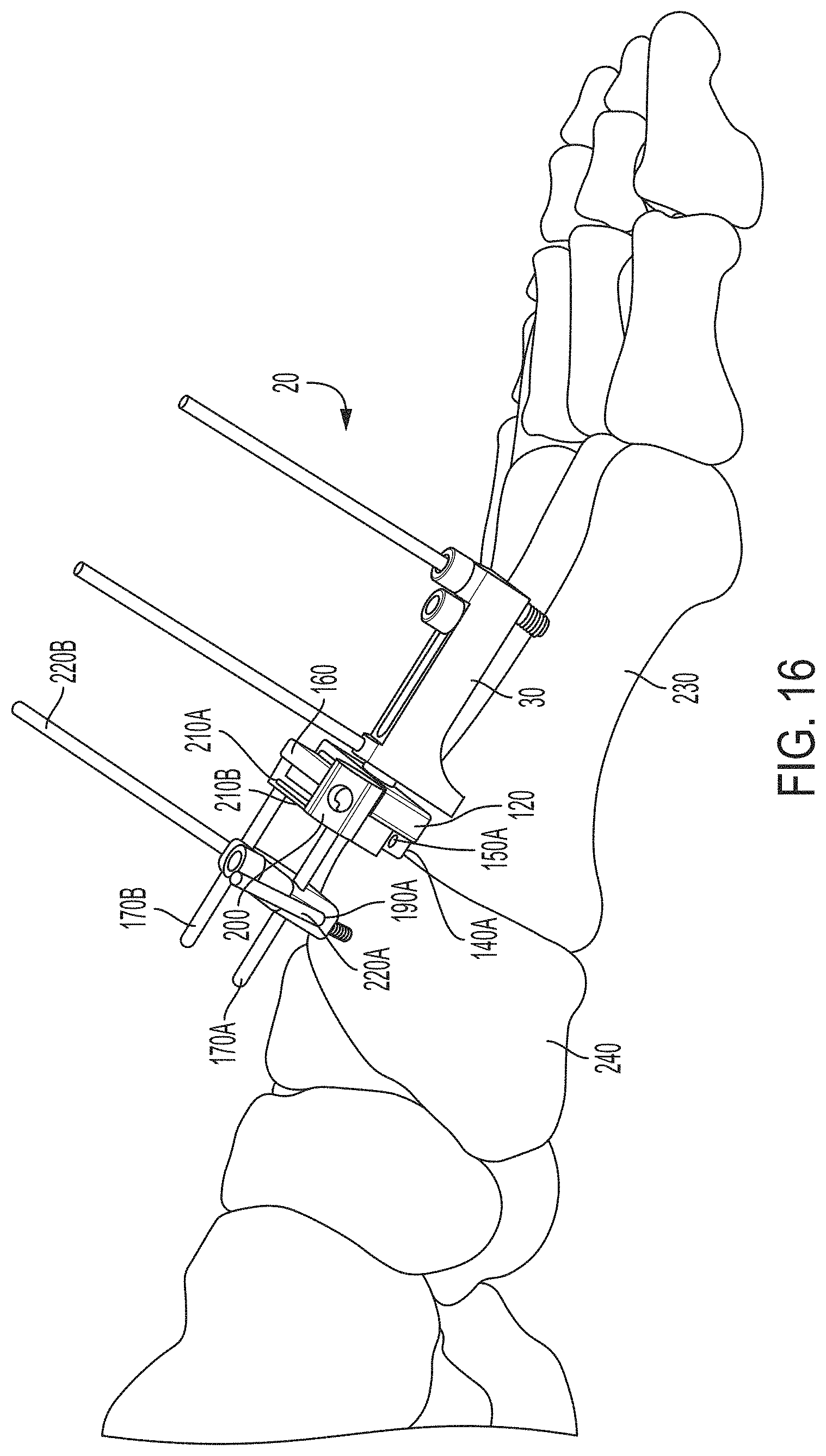
XML
uspto.report is an independent third-party trademark research tool that is not affiliated, endorsed, or sponsored by the United States Patent and Trademark Office (USPTO) or any other governmental organization. The information provided by uspto.report is based on publicly available data at the time of writing and is intended for informational purposes only.
While we strive to provide accurate and up-to-date information, we do not guarantee the accuracy, completeness, reliability, or suitability of the information displayed on this site. The use of this site is at your own risk. Any reliance you place on such information is therefore strictly at your own risk.
All official trademark data, including owner information, should be verified by visiting the official USPTO website at www.uspto.gov. This site is not intended to replace professional legal advice and should not be used as a substitute for consulting with a legal professional who is knowledgeable about trademark law.