Mechanical locking system for building panels
Hakansson , et al. December 22, 2
U.S. patent number 10,871,179 [Application Number 16/228,975] was granted by the patent office on 2020-12-22 for mechanical locking system for building panels. This patent grant is currently assigned to VALINGE INNOVATION AB. The grantee listed for this patent is VALINGE INNOVATION AB. Invention is credited to Niclas Hakansson, Darko Pervan.


View All Diagrams
| United States Patent | 10,871,179 |
| Hakansson , et al. | December 22, 2020 |
Mechanical locking system for building panels
Abstract
Panels are shown which are provided with a mechanical locking system allowing perpendicular connection with a snap action. A set of panels including a first and a second panel, an edge of the second panel is insertable into a groove of the first panel, when the panels are arranged essential perpendicular to each other, to obtain a mechanical connection between the first and the second panel, when the second panel is displaced essentially perpendicularly to the first panel.
| Inventors: | Hakansson; Niclas (Viken, SE), Pervan; Darko (Viken, SE) | ||||||||||
|---|---|---|---|---|---|---|---|---|---|---|---|
| Applicant: |
|
||||||||||
| Assignee: | VALINGE INNOVATION AB (Viken,
SE) |
||||||||||
| Family ID: | 1000005256807 | ||||||||||
| Appl. No.: | 16/228,975 | ||||||||||
| Filed: | December 21, 2018 |
Prior Publication Data
| Document Identifier | Publication Date | |
|---|---|---|
| US 20190113061 A1 | Apr 18, 2019 | |
Related U.S. Patent Documents
| Application Number | Filing Date | Patent Number | Issue Date | ||
|---|---|---|---|---|---|
| 15379791 | Dec 15, 2016 | 10202996 | |||
| 14515988 | Jan 10, 2017 | 9538842 | |||
| 13464512 | Nov 18, 2014 | 8887468 | |||
| 61483444 | May 6, 2011 | ||||
| Current U.S. Class: | 1/1 |
| Current CPC Class: | F16B 12/125 (20130101); A47B 47/042 (20130101); A47B 47/0066 (20130101); A47B 47/0075 (20130101); F16B 5/0056 (20130101); F16B 12/26 (20130101); E04F 2201/0146 (20130101); Y10T 403/73 (20150115); E04F 2201/0535 (20130101); E04F 2201/0523 (20130101) |
| Current International Class: | A47B 47/00 (20060101); F16B 5/00 (20060101); F16B 12/12 (20060101); F16B 12/26 (20060101); A47B 47/04 (20060101) |
References Cited [Referenced By]
U.S. Patent Documents
| 291032 | January 1884 | Cleland |
| 634581 | October 1899 | Miller |
| 701000 | May 1902 | Ahrens |
| 861911 | July 1907 | Stewart |
| 881673 | March 1908 | Ellison |
| 1533099 | April 1925 | Carroll |
| 1534468 | April 1925 | Shea, Jr. |
| 1800386 | April 1931 | Hoffman |
| 1800387 | April 1931 | Greist |
| 1802245 | April 1931 | Foretich |
| 1954242 | April 1934 | Heppenstall |
| 2360451 | October 1944 | Stone |
| 2362904 | November 1944 | Kramer |
| 2496184 | January 1950 | Von Canon |
| 2681483 | June 1954 | Morawetz |
| 3002630 | October 1961 | Heisser |
| 3195968 | July 1965 | Freeman |
| 3284152 | November 1966 | Schorghuber |
| 3313054 | April 1967 | Madey |
| 3347610 | October 1967 | Pilliod |
| 3410441 | November 1968 | Rhyne |
| 3722704 | March 1973 | Piretti |
| 3722971 | March 1973 | Zeischegg |
| 3742807 | July 1973 | Manning |
| 3765465 | October 1973 | Gulistan |
| 3784271 | January 1974 | Schreiber |
| 3884002 | May 1975 | Logie |
| 3885845 | May 1975 | Krieks |
| 3981118 | September 1976 | Johnson et al. |
| 4089614 | May 1978 | Harley |
| 4099887 | July 1978 | Mackenroth |
| 4116510 | September 1978 | Franco |
| 4142271 | March 1979 | Busse |
| 4211379 | July 1980 | Morgan et al. |
| 4222544 | September 1980 | Crowder |
| 4279397 | July 1981 | Larsson |
| 4299067 | November 1981 | Bertschi |
| 4308961 | January 1982 | Kunce |
| 4324517 | April 1982 | Dey |
| 4403886 | September 1983 | Haeusler |
| 4405253 | September 1983 | Stockum |
| 4509648 | April 1985 | Govang |
| 4593734 | June 1986 | Wallace |
| 4595105 | June 1986 | Gold |
| 4597122 | July 1986 | Handler |
| 4615448 | October 1986 | Johnstonbaugh |
| 4629076 | December 1986 | Amstutz et al. |
| 4750794 | June 1988 | Vegh |
| 4752150 | June 1988 | Salice |
| 4815908 | March 1989 | Duran et al. |
| 4817900 | April 1989 | Whittington et al. |
| 4844266 | July 1989 | Small et al. |
| 4883331 | November 1989 | Mengel |
| 4886326 | December 1989 | Kuzyk |
| 4888933 | December 1989 | Guomundsson |
| 4891897 | January 1990 | Gieske et al. |
| 4909581 | March 1990 | Haheeb |
| 4938625 | July 1990 | Matsui |
| 4944416 | July 1990 | Petersen et al. |
| 4961295 | October 1990 | Kosch, Sr. et al. |
| 5004116 | April 1991 | Cattarozzi |
| 5018323 | May 1991 | Clausen |
| 5109993 | May 1992 | Hutchison |
| 5114265 | May 1992 | Grisley |
| 5121578 | June 1992 | Holz |
| 5125518 | June 1992 | Ward |
| 5138803 | August 1992 | Grossen |
| 5209556 | May 1993 | Anderson |
| 5212925 | May 1993 | McClinton |
| 5299509 | April 1994 | Ballard |
| 5360121 | November 1994 | Sothman |
| 5375802 | December 1994 | Branham, II |
| 5423155 | June 1995 | Bauer |
| 5451102 | September 1995 | Chuan |
| 5458433 | October 1995 | Statsny |
| 5471804 | December 1995 | Winter, IV |
| 5475960 | December 1995 | Lindal |
| 5499667 | March 1996 | Nakanishi |
| 5499886 | March 1996 | Short et al. |
| 5507331 | April 1996 | Nakanishi |
| 5527103 | June 1996 | Pittman |
| 5536108 | July 1996 | Kvalheim |
| 5658086 | August 1997 | Brokaw et al. |
| 5711115 | January 1998 | Wirt |
| 5775521 | July 1998 | Tisbo |
| 5810505 | September 1998 | Henriott |
| 5893617 | April 1999 | Lee |
| 5941026 | August 1999 | Eisenreich |
| 5944294 | August 1999 | Baer |
| 5950389 | September 1999 | Porter |
| 6045290 | April 2000 | Nocievski |
| 6050426 | April 2000 | Leurdijk |
| 6142436 | November 2000 | Thurston et al. |
| 6312186 | November 2001 | Rock et al. |
| 6349507 | February 2002 | Muellerleile |
| 6363645 | April 2002 | Hunter |
| 6413007 | July 2002 | Lambright |
| 6418683 | July 2002 | Martensson |
| 6491172 | December 2002 | Chance |
| 6505452 | January 2003 | Hannig |
| 6547086 | April 2003 | Harvey |
| 6578498 | June 2003 | Draudt et al. |
| 6675979 | January 2004 | Taylor |
| D486676 | February 2004 | Campbell et al. |
| 6769219 | August 2004 | Schwitte et al. |
| 6772890 | August 2004 | Campbell et al. |
| 6827028 | December 2004 | Callaway |
| 6971614 | December 2005 | Fischer et al. |
| 7127860 | October 2006 | Pervan |
| 7223045 | May 2007 | Migli |
| 7228977 | June 2007 | Perkins et al. |
| 7300120 | November 2007 | Shin |
| 7451535 | November 2008 | Wells et al. |
| 7451578 | November 2008 | Hannig |
| 7584583 | September 2009 | Bergelin et al. |
| 7614350 | November 2009 | Tuttle et al. |
| 7621092 | November 2009 | Groeke et al. |
| 7641414 | January 2010 | Joyce |
| 7717278 | May 2010 | Kao |
| 7721503 | May 2010 | Pervan et al. |
| 7793450 | September 2010 | Chasmer et al. |
| 7818939 | October 2010 | Bearinger |
| 7998549 | August 2011 | Susnjara |
| 8033074 | October 2011 | Pervan |
| 8038363 | October 2011 | Hannig |
| 8042311 | October 2011 | Pervan |
| 8146754 | April 2012 | Apgood |
| 8220217 | July 2012 | Muehlebach |
| 8234830 | August 2012 | Pervan |
| 8365499 | February 2013 | Nilsson et al. |
| 8387327 | March 2013 | Pervan |
| 8464408 | June 2013 | Hazzard |
| 8495849 | July 2013 | Pervan |
| 8505257 | August 2013 | Boo et al. |
| 8544230 | October 2013 | Pervan |
| 8596013 | December 2013 | Boo |
| 8602227 | December 2013 | McDonald |
| 8615952 | December 2013 | Engstrom |
| 8713886 | May 2014 | Pervan |
| 8745952 | June 2014 | Perra |
| 8764137 | July 2014 | Fehre |
| 8776473 | July 2014 | Pervan |
| 8833028 | September 2014 | Whispell et al. |
| 8864407 | October 2014 | Sorum |
| 8882416 | November 2014 | Baur et al. |
| 8887468 | November 2014 | Hakansson et al. |
| 9175703 | November 2015 | Maertens |
| 9216541 | December 2015 | Boo |
| 9290948 | March 2016 | Cappelle et al. |
| 9375085 | June 2016 | Derelov |
| 9538842 | January 2017 | Hakansson et al. |
| 9655442 | May 2017 | Boo et al. |
| 9714672 | July 2017 | Derelov et al. |
| 9723923 | August 2017 | Derelov |
| 9726210 | August 2017 | Derelov et al. |
| 9745756 | August 2017 | Hannig |
| 9809983 | November 2017 | Trudel |
| 9945121 | April 2018 | Derelov |
| 10034541 | July 2018 | Boo et al. |
| 10202996 | February 2019 | Hakansson et al. |
| 10378570 | August 2019 | Broughton |
| 10415613 | September 2019 | Boo |
| 10448739 | October 2019 | Derelov et al. |
| 10451097 | October 2019 | Brannstrom et al. |
| 10486245 | November 2019 | Fridlund |
| 10506875 | December 2019 | Boo et al. |
| 10544818 | January 2020 | Fridlund |
| 10548397 | February 2020 | Derelov et al. |
| 10669716 | June 2020 | Derelov et al. |
| 10670064 | June 2020 | Derelov et al. |
| 10830268 | November 2020 | Boo |
| 2002/0170258 | November 2002 | Schwitte et al. |
| 2004/0165946 | August 2004 | Areh et al. |
| 2005/0042027 | February 2005 | Migli |
| 2005/0236544 | October 2005 | Mancino |
| 2005/0247653 | November 2005 | Brooks |
| 2006/0091093 | May 2006 | Armari |
| 2006/0101769 | May 2006 | Pervan |
| 2006/0180561 | August 2006 | Wisnoski et al. |
| 2006/0236642 | October 2006 | Pervan |
| 2006/0273085 | December 2006 | Casto |
| 2007/0006543 | January 2007 | Engstrom |
| 2007/0028547 | February 2007 | Grafenauer et al. |
| 2008/0010937 | January 2008 | Pervan et al. |
| 2008/0066415 | March 2008 | Pervan |
| 2008/0193209 | August 2008 | Henderson |
| 2008/0216435 | September 2008 | Nolan |
| 2008/0236088 | October 2008 | Hannig et al. |
| 2008/0244882 | October 2008 | Woxman et al. |
| 2009/0014401 | January 2009 | Tallman |
| 2009/0064624 | March 2009 | Sokol |
| 2010/0028592 | February 2010 | Barkdoll et al. |
| 2010/0083603 | April 2010 | Goodwin |
| 2010/0104354 | April 2010 | Spalding |
| 2010/0173122 | July 2010 | Susnjara |
| 2010/0289389 | November 2010 | Crabtree, II |
| 2011/0023303 | February 2011 | Pervan et al. |
| 2011/0225921 | September 2011 | Schulte |
| 2011/0225922 | September 2011 | Pervan et al. |
| 2011/0280655 | November 2011 | Maertens et al. |
| 2011/0283650 | November 2011 | Pervan et al. |
| 2012/0009383 | January 2012 | Hardesty |
| 2012/0027967 | February 2012 | Maertens et al. |
| 2012/0073235 | March 2012 | Hannig |
| 2012/0124932 | May 2012 | Schulte et al. |
| 2012/0145845 | June 2012 | Hightower |
| 2012/0180416 | July 2012 | Perra et al. |
| 2012/0279161 | November 2012 | Hakansson et al. |
| 2012/0286637 | November 2012 | Fehre |
| 2013/0014463 | January 2013 | Pervan |
| 2013/0048632 | February 2013 | Chen |
| 2013/0071172 | March 2013 | Maertens et al. |
| 2013/0081349 | April 2013 | Pervan |
| 2013/0097846 | April 2013 | Pettigrew |
| 2013/0111845 | May 2013 | Pervan |
| 2013/0170904 | July 2013 | Cappelle et al. |
| 2013/0232905 | September 2013 | Pervan |
| 2013/0287484 | October 2013 | Phillips |
| 2014/0013919 | January 2014 | Gerke et al. |
| 2014/0055018 | February 2014 | Shein et al. |
| 2014/0111076 | April 2014 | Devos |
| 2015/0035422 | February 2015 | Hakansson et al. |
| 2015/0078807 | March 2015 | Brannstrom et al. |
| 2015/0078819 | March 2015 | Derelov et al. |
| 2015/0196118 | July 2015 | Derelov |
| 2015/0198191 | July 2015 | Boo |
| 2015/0330088 | November 2015 | Derelov |
| 2016/0007751 | January 2016 | Derelov |
| 2016/0174704 | June 2016 | Boo et al. |
| 2016/0270531 | September 2016 | Derelov |
| 2017/0079433 | March 2017 | Derelov et al. |
| 2017/0089379 | March 2017 | Pervan |
| 2017/0097033 | April 2017 | Hakansson et al. |
| 2017/0159291 | June 2017 | Derelov |
| 2017/0208938 | July 2017 | Derelov et al. |
| 2017/0227031 | August 2017 | Boo |
| 2017/0227032 | August 2017 | Fridlund |
| 2017/0227035 | August 2017 | Fridlund |
| 2017/0234346 | August 2017 | Fridlund |
| 2017/0298973 | October 2017 | Derelov |
| 2017/0360193 | December 2017 | Boo et al. |
| 2018/0080488 | March 2018 | Derelov |
| 2018/0087552 | March 2018 | Derelov et al. |
| 2018/0112695 | April 2018 | Boo et al. |
| 2018/0119717 | May 2018 | Derelov |
| 2018/0202160 | July 2018 | Derelov |
| 2018/0328396 | November 2018 | Fransson et al. |
| 2019/0166989 | June 2019 | Boo et al. |
| 2019/0191870 | June 2019 | Derelov |
| 2019/0195256 | June 2019 | Derelov |
| 2019/0289999 | September 2019 | Derelov et al. |
| 2019/0320793 | October 2019 | Boo |
| 2019/0323532 | October 2019 | Boo |
| 2019/0323533 | October 2019 | Boo |
| 2019/0323534 | October 2019 | Derelov |
| 2019/0323535 | October 2019 | Derelov |
| 2020/0003242 | January 2020 | Brannstrom et al. |
| 2020/0055126 | February 2020 | Fridlund |
| 2020/0069048 | March 2020 | Derelov et al. |
| 2020/0069049 | March 2020 | Derelov et al. |
| 2020/0102978 | April 2020 | Fridlund |
| 2020/0121076 | April 2020 | Derelov et al. |
| 2020/0214447 | July 2020 | Derelov et al. |
| 2020/0300284 | September 2020 | Pervan |
| 2020/0337455 | October 2020 | Boo et al. |
| 2020/0340513 | October 2020 | Derelov |
| 365 507 | Nov 1962 | CH | |||
| 685 276 | May 1995 | CH | |||
| 696 889 | Jan 2008 | CH | |||
| 696889 | Jan 2008 | CH | |||
| 698 988 | Dec 2009 | CH | |||
| 101099618 | Jan 2008 | CN | |||
| 1107910 | May 1961 | DE | |||
| 24 14 104 | Oct 1975 | DE | |||
| 25 14 357 | Oct 1975 | DE | |||
| 31 03 281 | Aug 1982 | DE | |||
| 228 872 | Oct 1985 | DE | |||
| 42 29 115 | Mar 1993 | DE | |||
| 94 17 168 | Feb 1995 | DE | |||
| 198 31 936 | Feb 1999 | DE | |||
| 298 20 031 | Feb 1999 | DE | |||
| 198 05 538 | Aug 1999 | DE | |||
| 203 04 761 | Apr 2004 | DE | |||
| 299 24 630 | May 2004 | DE | |||
| 20 2005 019 986 | Feb 2006 | DE | |||
| 20 2004 017 486 | Apr 2006 | DE | |||
| 20 2009 008 825 | Oct 2009 | DE | |||
| 10 2008 035 293 | Feb 2010 | DE | |||
| 10 2009 041 142 | Mar 2011 | DE | |||
| 10 2013 008 595 | Nov 2013 | DE | |||
| 0 060 203 | Sep 1982 | EP | |||
| 0 060 203 | Sep 1982 | EP | |||
| 0 357 129 | Mar 1990 | EP | |||
| 0 362 968 | Apr 1990 | EP | |||
| 0 675 332 | Oct 1995 | EP | |||
| 0 871 156 | Oct 1998 | EP | |||
| 1 048 423 | Nov 2000 | EP | |||
| 1 048 423 | May 2005 | EP | |||
| 1 650 375 | Apr 2006 | EP | |||
| 1 671 562 | Jun 2006 | EP | |||
| 1 650 375 | Sep 2006 | EP | |||
| 1 922 954 | May 2008 | EP | |||
| 2 017 403 | Jan 2009 | EP | |||
| 1 922 954 | Jul 2009 | EP | |||
| 2 333 353 | Jun 2011 | EP | |||
| 1 863 984 | Nov 2011 | EP | |||
| 2 487 373 | Aug 2012 | EP | |||
| 2 517 187 | Jun 1983 | FR | |||
| 2 597 173 | Oct 1987 | FR | |||
| 2 602 013 | Jan 1988 | FR | |||
| 245332 | Jan 1926 | GB | |||
| 1 022 377 | Mar 1966 | GB | |||
| 2 163 825 | Mar 1986 | GB | |||
| 2 315 988 | Feb 1998 | GB | |||
| 2 445 954 | Jul 2008 | GB | |||
| 2 482 213 | Jan 2012 | GB | |||
| S53-113160 | Sep 1978 | JP | |||
| H06-22606 | Mar 1994 | JP | |||
| 2003-239921 | Aug 2003 | JP | |||
| 10-1147274 | May 2012 | KR | |||
| WO 87/07339 | Dec 1987 | WO | |||
| WO 90/07066 | Jun 1990 | WO | |||
| WO 99/22150 | May 1999 | WO | |||
| WO 99/41508 | Aug 1999 | WO | |||
| WO 00/66856 | Nov 2000 | WO | |||
| WO 01/53628 | Jul 2001 | WO | |||
| WO 02/055809 | Jul 2002 | WO | |||
| WO 02/055810 | Jul 2002 | WO | |||
| WO 03/083234 | Oct 2003 | WO | |||
| WO 2004/079130 | Sep 2004 | WO | |||
| WO 2005/068747 | Jul 2005 | WO | |||
| WO 2006/043893 | Apr 2006 | WO | |||
| WO 2006/104436 | Oct 2006 | WO | |||
| WO 2007/015669 | Feb 2007 | WO | |||
| WO 2007/015669 | Feb 2007 | WO | |||
| WO 2008/004960 | Jan 2008 | WO | |||
| WO 2008/004960 | Jan 2008 | WO | |||
| WO 2008/004960 | Jan 2008 | WO | |||
| WO 2008/017281 | Feb 2008 | WO | |||
| WO 2008/150234 | Dec 2008 | WO | |||
| WO 2010/087752 | Aug 2010 | WO | |||
| WO 2011/151758 | Dec 2011 | WO | |||
| WO 2011/151758 | Dec 2011 | WO | |||
| WO-2011151737 | Dec 2011 | WO | |||
| WO-2011151758 | Dec 2011 | WO | |||
| WO 2012/095454 | Jul 2012 | WO | |||
| WO-2012095454 | Jul 2012 | WO | |||
| WO 2012/154113 | Nov 2012 | WO | |||
| WO 2013/009257 | Jan 2013 | WO | |||
| WO 2013/025163 | Feb 2013 | WO | |||
| WO 2013/080160 | Jun 2013 | WO | |||
| WO 2013/118075 | Aug 2013 | WO | |||
| WO-2013118075 | Aug 2013 | WO | |||
Other References
|
US. Appl. 14/486,681, Hans Brannstrom, Agne Palsson and Peter Derelov, filed Sep. 15, 2014, (Cited herein as US Patent Application Publication No. 2015/0078807 A1 of Mar. 19, 2015). cited by applicant . U.S. Appl. 14/573,572, Christian Boo, filed Dec. 17, 2014, (Cited herein as US Patent Application Publication No. 2015/0198191 A1 of Jul. 16, 2015). cited by applicant . U.S. Appl. 15/271,622, Peter Derelov and Mats Nilsson, filed Sep. 21, 2016, (Cited herein as US Patent Application Publication No. 2017/0079433 A1 of Mar. 23, 2017). cited by applicant . U.S. Appl. 15/308,872, Darko Pervan, filed Nov. 4, 2016, (Cited herein as US Patent Application Publication No. 2017/0089379 A1 of Mar. 30, 2017). cited by applicant . U.S. Appl. 15/415,356, Peter Derelov and Christian Boo, filed Jan. 25, 2017, (Cited herein as US Patent Application Publication No. 2017/0208938 A1 of Jul. 27, 2017). cited by applicant . U.S. Appl. 15/422,798, Magnus Fridlund, filed Feb. 2, 2017, (Cited herein as US Patent Application Publication No. 2017/0227035 A1 of Aug. 10, 2017). cited by applicant . U.S. Appl. 15/428,469, Magnus Fridlund, filed Feb. 9, 2017, (Cited herein as US Patent Application Publication No. 2017/0227032 A1 of Aug. 10, 2017). cited by applicant . U.S. Appl. 15/428,504, Christian Boo, filed Feb. 9, 2017, (Cited herein as US Patent Application Publication No. 2017/0227031 A1 of Aug. 10, 2017). cited by applicant . U.S. Appl. 15/432,190, Magnus Fridlund, filed Feb. 14, 2017, (Cited herein as US Patent Application Publication No. 2017/0234346 A1 of Aug. 17, 2017). cited by applicant . U.S. Appl. 15/642,757, Peter Derelov, filed Jul. 6, 2017, (Cited herein as US Patent Application Publication No. 2017/0298973 A1 of Oct. 19, 2017). cited by applicant . U.S. Appl. 15/646,714, Peter Derelov, filed Jul. 11, 2017, (Cited herein as US Patent Application Publication No. 2018/0087552 A1 of Mar. 29, 2018). cited by applicant . U.S. Appl. 15/562,254, Peter Derelov, filed Sep. 27, 2017, (Cited herein as US Patent Application Publication No. 2018/0080488 A1 of Mar. 22, 2018). cited by applicant . U.S. Appl. 15/567,507, Christian Boo, Peter Derelov, and Agne Palsson, filed Oct. 18, 2017, (Cited herein as US Patent Application Publication No. 2018/0112695 A1 of Apr. 26, 2018). cited by applicant . U.S. Appl. 15/794,491, Peter Derelov, filed Oct. 26, 2017, (Cited herein as US Patent Application Publication No. 2018/0119717 A1 of May 3, 2018). cited by applicant . U.S. Appl. 15/923,701, Peter Derelov, filed Mar. 16, 2018, (Cited herein as US Patent Application Publication No. 2018/0202160 A1 of Jul. 19, 2018). cited by applicant . U.S. Appl. 15/978,630, Jonas Fransson, Niclas Hakansson and and Agne Palsson, filed May 14, 2018, (Cited herein as US Patent Application Publication No. 2018/0328396 A1 of Nov. 15, 2018). cited by applicant . U.S. Appl. No. 15/956,949, Peter Derelov, filed Apr. 19, 2018. cited by applicant . U.S. Appl. No. 16/027,479 Christian Boo and Peter Derelov Jul. 5, 2018. cited by applicant . U.S. Appl. No. 16/220,574, Peter Derelov, filed Dec. 14, 2018. cited by applicant . U.S. Appl. No. 16/220,585, Peter Derelov, filed Dec. 14, 2018. cited by applicant . U.S. Appl. No. 16/361,609, Peter Derelov, Johan Svensson and Lars Gunnarsson, filed Mar. 22, 2019. cited by applicant . U.S. Appl. No. 16/386,732, Christian Boo, filed Apr. 17, 2019. cited by applicant . U.S. Appl. No. 16/386,810, Christian Boo, filed Apr. 17, 2019. cited by applicant . U.S. Appl. No. 16/386,824, Christian Boo, filed Apr. 17, 2019. cited by applicant . U.S. Appl. No. 16/386,874, Peter Derelov, filed Apr. 17, 2019. cited by applicant . U.S. Appl. No. 15/956,949, Derelov cited by applicant . U.S. Appl. No. 16/027,479, Boo, et al. cited by applicant . U.S. Appl. No. 16/220,574, Derelov. cited by applicant . U.S. Appl. No. 16/220,585, Derelov cited by applicant . U.S. Appl. No. 16/361,609, Derelov et al. cited by applicant . U.S. Appl. No. 16/386,732, Boo. cited by applicant . U.S. Appl. No. 16/386,810, Boo. cited by applicant . U.S. Appl. No. 16/386,824, Boo. cited by applicant . U.S. Appl. No. 16/386,874, Derelov cited by applicant . International Search Report dated Aug. 2, 2012 in PCT/SE2012/050475, Swedish Patent Office, Stockholm, Sweden, 8 pages. cited by applicant . Extended European Search Report issued in EP Patent Application No. 12782144.5, dated Aug. 14, 2014, European Patent Office, Munich, DE, 9 pages. cited by applicant . Extended European Search Report issued in EP Patent Application No. 17202290.7, dated Feb. 12, 2018, European Patent Office, Munich, DE, 10 pages. cited by applicant . Derelov, Peter, U.S. Appl. No. 15/956,949 entitled "Panels for an Assembled Product", filed in the U.S. Patent and Trademark Office on Apr. 19, 2018. cited by applicant . Boo, Christian, et al., U.S. Appl. No. 16/027,479 entitled "Panels Comprising a Mechanical Locking Device and an Assembled Product Comprising the Panels," filed in the U.S. Patent and Trademark Office on Jul. 5, 2018. cited by applicant . Derelov, Peter, U.S. Appl. No. 16/220,574 entitled "Set of Panels," filed in the U.S. Patent and Trademark Office on Dec. 14, 2018. cited by applicant . Derelov, Peter, U.S. Appl. No. 16/220,585 entitled "Set of Panels," filed in the U.S. Patent and Trademark Office on Dec. 14, 2018. cited by applicant . Derelov, Peter, et al., U.S. Appl. No. 16/361,609 entitled "Panels Comprising a Mechanical Locking Device and an Assembled Product Comprising the Panels," filed in the U.S. Patent and Trademark Office on Mar. 22, 2019. cited by applicant . Boo, Christian, U.S. Appl. No. 16/386,732 entitled "Set of Panels With a Mechanical Locking Device," filed in the U.S. Patent and Trademark Office on Apr. 17, 2019. cited by applicant . Boo, Christian, U.S. Appl. No. 16/386,810 entitled "Set of Panels With a Mechanical Locking Device," filed in the U.S. Patent and Trademark Office on Apr. 17, 2019. cited by applicant . Boo, Christian, U.S. Appl. No. 16/386,824 entitled "Set of Panels With a Mechanical Locking Device," filed in the U.S. Patent and Trademark Office on Apr. 17, 2019. cited by applicant . Derelov, Peter, U.S. Appl. No. 16/386,874 entitled "Symmetric Tongue and T-Cross," filed in the U.S. Patent and Trademark Office on Apr. 17, 2019. cited by applicant . U.S. Appl. No. 16/564,438, Hans Brannstrom, Agne Palsson and Peter Derelov, filed Sep. 9, 2019, (Cited herein as US Patent Application Publication No. 2020/0003242 A1 of Jan. 2, 2020). cited by applicant . U.S. Appl. No. 16/553,325 Peter Derelov and Johan Svensson, filed Aug. 28, 2019. cited by applicant . U.S. Appl. No. 16/553,350, Peter Derelov and Johan Svensson, filed Aug. 28, 2019. cited by applicant . U.S. Appl. No. 16/567,436 Peter Derelov and Mats Nilsson, filed Sep. 11, 2019. cited by applicant . U.S. Appl. No. 16/663,603 Magnus Fridlund, filed Oct. 25, 2019. cited by applicant . U.S. Appl. No. 16/697,335, Christian Boo and Peter Derelov, filed Nov. 27, 2019. cited by applicant . U.S. Appl. No. 16/703,077, Magnus Fridlund, filed Dec. 4, 2019. cited by applicant . U.S. Appl. No. 16/722,096, Peter Derelov and Christian Boo, filed Dec. 20. 2019. cited by applicant . U.S. Appl. No. 16/553,325, Derelov et al. cited by applicant . U.S. Appl. No. 16/553,350, Derelov et al. cited by applicant . U.S. Appl. No. 16/567,436, Derelov. cited by applicant . U.S. Appl. No. 16/663,603, Fridlund. cited by applicant . U.S. Appl. No. 16/697,335, Boo et al. cited by applicant . U.S. Appl. No. 16/703,077, Fridlund. cited by applicant . U.S. Appl. No. 16/722,096, Derelov et al. cited by applicant . Derelov, Peter, U.S. Appl. No. 16/553,325, entitled "Set of Panels with a Mechanical Locking Device," filed in the U.S. Patent and Trademark Office on Aug. 28, 2019. cited by applicant . Derelov, Peter, U.S. Appl. No. 16/553,350 entitled "Set of Panels with a Mechanical Locking Device," filed in the U.S. Patent and Trademark Office on Aug. 28, 2019. cited by applicant . Derelov, Peter, U.S. Appl. No. 16/567,436 entitled "Panels Comprising a Mechanical Locking Device and an Assembled Product Comprising the Panels," filed in the U.S. Patent and Trademark Office on Sep. 11, 2019. cited by applicant . Fridlund, Magnus, U.S. Appl. No. 16/663,603 entitled "Element and Method for Providing Dismantling Groove," filed in the U.S. Patent and Trademark Office on Oct. 25, 2019. cited by applicant . Boo, Christian, et al., U.S. Patent Application No. 16/697,335 entitled "Panels Comprising a Mechanical Locking Device and an Assembled Product Comprising the Panels," filed in the U.S. Patent and Trademark Office on Nov. 27, 2019. cited by applicant . Fridlund, Magnus, U.S. Appl. No. 16/703,077 entitled "Set of Panels for an Assembled Product," filed in the U.S. Patent and Trademark Office Dec. 4, 2019. cited by applicant . Derelov, Peter, et al., U.S. Appl. No. 16/722,096 entitled "Panels Comprising a Mechanical Locking Device and an Assembled Product Comprising the Panels," filed in the U.S. Patent and Trademark Office on Dec. 20, 2019. cited by applicant . Extended European Search Report issued in EP Patent Application No. 19217996.8, dated Jan. 31, 2020, European Patent Office, Munich, DE, 11 pages. cited by applicant . U.S. Appl. No. 16/861,639, Peter Derelov. cited by applicant . Derelov, Peter, U.S. Appl. No. 16/861,639 entitled "Panels Comprising a Mechanical Locking Device and an Assembled Product Comprising the Panels," filed in the U.S. Patent and Trademark Office on Apr. 29, 2020. cited by applicant . U.S. Appl. No. 16/861,639, Derelov. cited by applicant . U.S. Appl. No. 16/946,047, Darko Pervan, filed Jun. 4, 2020. cited by applicant . U.S. Appl. No. 16/915,258, Hans Brannstrom, Agne Palsson and Peter Derelov, filed Jun. 29, 2020. cited by applicant . Pervan, Darko, U.S. Appl. No. 16/946,047 entitled "Mechanical Locking System for Building Panels," filed in the U.S. Patent and Trademark Office on Jun. 4, 2020. cited by applicant . Brannstrom, Hans, et al., U.S. Appl. No. 16/915,258 entitled "Assembled Product and Method of Assembling the Assembled Product," filed in the U.S. Patent and Trademark Office on Jun. 29, 2020. cited by applicant . U.S. Appl. No. 16/946,047, Pervan. cited by applicant . U.S. Appl. No. 16/915,258, Brannstrom et al. cited by applicant. |
Primary Examiner: Kwiecinski; Ryan D
Attorney, Agent or Firm: Buchanan Ingersoll & Rooney P.C.
Parent Case Text
CROSS REFERENCE TO RELATED APPLICATIONS
The present application is a continuation of U.S. patent application Ser. No. 15/379,791, filed on Dec. 15, 2016, which is a continuation of Ser. No. 14/515,988, filed on Oct. 16, 2014, now U.S. Pat. No. 9,538,842, which is a continuation of U.S. application Ser. No. 13/464,512, filed on May 4, 2012, now U.S. Pat. No. 8,887,468, which claims the benefit of U.S. Provisional Application No. 61/483,444, filed on May 6, 2011. The entire contents of each of U.S. application Ser. No. 15/379,791, U.S. application Ser. No. 13/464,512, U.S. Provisional Application No. 61/483,444 and Swedish Application No. 1150400-8 are hereby incorporated herein by reference.
Claims
The invention claimed is:
1. A set of furniture components provided with a mechanical locking system for locking a first panel and a second panel essentially perpendicularly to each other, the mechanical locking system comprising: a groove provided in the first panel; an edge of the second panel; an insertion groove provided in the groove of the first panel or in the edge of the second panel; a tongue groove provided in the edge of the second panel or in the groove of the first panel; and a separate and flexible tongue provided in the insertion groove, wherein the edge of the second panel is configured to be inserted into the groove of the first panel for locking the panels to each other in a direction perpendicular to a main plane of the second panel, wherein the separate and flexible tongue is configured to cooperate with the tongue groove for locking the panels to each other in a direction perpendicular to the main plane of the first panel, wherein the insertion groove, the tongue groove, and the separate and flexible tongue are arranged and configured such that displacing the second panel essentially perpendicularly to the first panel causes the flexible tongue to be linearly displaced inwardly towards a bottom of the insertion groove and outwardly into the tongue groove during locking, and wherein the edge of the second panel or a portion of the groove of the first panel comprise(s) a separate material.
2. The set of furniture components according to claim 1, wherein the separate material of the first panel and/or the second panel is glued or mechanically connected to the second panel.
3. The set of furniture components according to claim 1, wherein the first panel and the second panel are particle board panels, wherein the separate material of the first panel and/or the second panel is separate material of the first panel and separate material of the second panel, and wherein the separate material of the first panel and the separate material of the second panel each comprise solid wood, plywood or HDF.
4. The set of furniture components according to claim 1, wherein the edge of the second panel is configured to be inserted into the groove of the first panel when main planes of the first panel and the second panel are arranged essentially perpendicularly to each other.
5. The set of furniture components according to claim 1, wherein the insertion groove is formed in a side wall of the groove of the first panel.
6. The set of furniture components according to claim 1, wherein the second panel comprises an outer edge having a smaller thickness than a panel body of the second panel.
7. The set of furniture components according to claim 6, wherein the panel body overlaps one or both parts of a groove opening when the edge of the second panel is inserted into the groove of the first panel.
8. The set of furniture components according to claim 6, wherein the separate material of the second panel forms the outer edge having a smaller thickness.
9. The set of furniture components according to claim 1, wherein the separate material of the first panel and/or the second panel is covered with a foil, paper, or paint.
10. The set of furniture components according to claim 1, wherein an inner part of the separate and flexible tongue is provided in the insertion groove and wherein an outer part of the separate and flexible tongue extends outside of the insertion groove in a locked state of the panels.
11. The set of furniture components according to claim 1, wherein the insertion groove is inclined upwards, a distance from an opening of the insertion groove to the main plane of the first panel being smaller than a distance from an inner part of the insertion groove to the main plane of the first panel, the main plane of the first panel being provided along a side surface of the first panel in which the groove is provided.
12. The set of furniture components according to claim 1, wherein the insertion groove is inclined such that a linear extension of a lower part of the insertion groove is located at or above the upper part of the opening of the groove.
13. The set of furniture components according to claim 1, wherein the separate and flexible tongue has two opposite displacement surfaces configured to be displaced against an upper wall and a lower wall of the insertion groove during locking.
14. The set of furniture components according to claim 1, wherein the separate and flexible tongue is configured to be locked with pretension against the tongue groove.
15. The set of furniture components according to claim 1, wherein the tongue groove provided in the edge of the second panel is provided in the separate material of the second panel.
16. The set of furniture components according to claim 1, wherein the insertion groove is a first insertion groove provided in a groove wall of the groove of the first panel, the tongue groove is a first tongue groove provided in the edge of the second panel, and the separate and flexible tongue is a first separate and flexible tongue, the mechanical locking system further comprising: a second insertion groove provided in an opposite groove wall of the groove of the first panel, a second tongue groove provided in the edge of the second panel, and a second separate and flexible tongue provided in the second insertion groove, wherein the second separate and flexible tongue is configured to cooperate with the second tongue groove for locking the panels to each other in the direction perpendicular to the main plane of the first panel.
17. The set of furniture components according to claim 1, wherein the mechanical locking system further comprises a plug and a hole configured to cooperate with each other.
18. A method of locking a first and a second panel, the method comprising inserting an edge of the second panel into a groove of the first panel, when the panels are arranged essential perpendicular to each other, to obtain a mechanical connection between the first and the second panel, the method comprising displacing the second panel essentially perpendicularly to the first panel, wherein: the edge comprises a separate and flexible tongue and the groove comprises a tongue groove, or the edge comprises a tongue groove and the groove comprises a separate and flexible tongue; the separate and flexible tongue is insertable into the tongue groove for connecting the panels to each other in a first direction, which is parallel to a main plane of the first panel; the edge of the second panel is configured to cooperate with the groove of the first panel for connecting the panels to each other in a second direction, which is parallel to a main plane of the second panel; a length direction of the separate and flexible tongue extends parallel with the edge and/or groove; the groove comprises an opening, two side walls and a bottom; the separate and flexible tongue is arranged in an insertion groove; the separate and flexible tongue has an inner part mounted in the insertion groove and an outer part extending outside an opening of the insertion groove; and the displacing of the second panel essentially perpendicularly to the first panel causes the flexible tongue to be linearly displaced inwardly towards a bottom of the insertion groove and outwardly into the tongue groove during locking.
Description
TECHNICAL FIELD
The disclosure relates to the field of mechanical locking systems for building panels, especially furniture components with mechanical locking systems, which are intended to lock preferably perpendicular to each other.
FIELD OF APPLICATION OF THE INVENTION
Embodiments of the present invention are particularly suitable for use in furniture components, which are preferably formed of sheet shaped panels and which are joined mechanically with a locking system integrated with the panel, i.e. mounted at the factory. The following description of known technology, problems of known systems and objects and features of the invention will therefore, as a non-restrictive example, be aimed above all at this field of application and in particular at furniture components formed as rectangular panels intended to be mechanically joined on one pair of opposite edges perpendicularly to other adjacent panels. The panels may also be square.
It should be emphasized that the invention can be applied to any type of sheet shaped panel such as for example wood based HDF, particle board and plywood, plastic sheet shaped materials, mineral fibre and metal based materials, stone and ceramics and similar. It may be used to connect furniture components, and elements for packaging boxes and similar. It may also be used to lock components, which for example have a cylinder form such as table legs.
BACKGROUND OF THE INVENTION
Furniture such as kitchen cabinets, bookshelves, drawers, tables and similar are generally supplied as flat components in order to save transportation costs. The customer must assemble them. Several methods are used to assemble such furniture components, for example, glue, spikes, screws and similar. Snapping connections comprising plastic components are widely used to connect, for example, drawers.
Known Technology and Problems Thereof
There are a lot of problems connected with the assembly of furniture components especially when one panel should be connected perpendicularly to another panel. Generally special connection devices are supplied that have to be inserted into grooves and holes. Such assembly is complicated and time consuming and the connection is often not strong enough. Snapping connections formed in plastic materials are expensive and complicated to produce. It would be an advantage if assembly may be simplified and if no loose parts would be needed in order to connect panels to each other in a firm, cost efficient and rigid manner.
WO 2010/070472 describes locking systems that may be used to assemble furniture components with angling and snapping. The locking systems may be formed in one piece with the panel or, alternatively, a separate plastic tongue with an outer flexible snap tab may be used. Such locking systems do not give sufficient strength and rigidity especially when rather soft core materials, such as particleboard, are used. The locking system is complicated to produce since the flexible tongue cannot be connected to the components with a linear displacement into a groove. The outer flexible part is generally not strong enough to provide a rigid connection.
SUMMARY OF THE INVENTION
A basic objective of embodiments of the present invention is to provide an improved mechanical locking system which may be produced in a cost effective way and which allows preferably rectangular panels to be connected and assembled mechanically perpendicularly to each other with a strong locking and in a simple manner without the need for loose parts that has to be used during assembly.
The above objects of embodiments of the invention are achieved wholly or partly by mechanical locking systems and panels, according to the independent claim that provide a stronger and easier locking. Embodiments of the invention are evident from the dependent claims and from the description and drawings.
A first aspect of the invention is a set of panels comprising a first and a second panel. An edge of the second panel is insertable into a groove of the first panel, when the panels are arranged essential perpendicular to each other, to obtain a mechanical connection between the first and the second panel, when the second panel is displaced essentially perpendicularly to the first panel. The edge comprises a separate and flexible tongue and said groove comprises a tongue groove, or said edge comprises a tongue groove and said groove comprises a separate and flexible tongue. The separate and flexible tongue is insertable into the tongue groove for connecting said panels to each other in a first direction, which is parallel to a main plane of the first panel. The edge of the second panel is configured to cooperate with the groove of the first panel for connecting said panels to each other in a second direction, which is parallel to a main plane (MP) of the second panel. The length direction of the separate and flexible tongue extends parallel with said edge and/or groove. The groove preferably comprises an opening, two sidewalls and a bottom. The separate and flexible tongue is arranged in an insertion groove. The separate and flexible tongue has an inner part mounted in the insertion groove and an outer part extending outside an opening of the insertion groove. A part of the separate tongue is displaced in the insertion groove during locking. The flexible tongue is preferably displaceable inwardly towards a bottom of the insertion groove and outwardly into the tongue groove during locking.
The tongue may comprise two opposite displacement surfaces located between the inner and outer parts of the separate and flexible tongue. One or both of said two opposite displacement surfaces may be displaceable against a wall(s) of the insertion groove during locking.
A locking involving displacement of a displacement surface against an upper or lower wall of the insertion groove may make it possible use a tongue with a rigid outer part. That may facilitate a strong locking even in rather soft materials such a particle boards that are often used a base material in furniture components. The outer rigid part may be displaced into a rather deep tongue groove and a firm locking may be obtained.
Said insertion groove may be inclined upwards with the opening closer to the main plane of the panel than the inner part of the insertion groove. Such inclination may facilitate the insertion of the separate tongue into the insertion groove during production since the tongue may be inserted with a linear motion into the displacement groove.
The separate and flexible tongue may, when the edge of the second panel is inserted into the groove of the first panel, lock by snapping.
The inner part may be fixed in the insertion groove by e.g. friction connection or by glue.
The inner part of the tongue may comprise one or several flexible protrusions extending in the length direction of the tongue.
The first and/or the second panel may comprise separate materials that form an edge or a groove portion. A particleboard panel may be reinforced with solid wood, plywood, HDF and similar wood based materials that are glued or mechanically connected to the panels in order to form at least a part of the locking system.
The second panel may have an outer edge with a smaller thickness than the thickness of the panel body such that the panel body overlaps one or both parts of the groove opening when the second panel is inserted into the groove of the first panel.
At least a part of the tongue and/or the groove may be formed in the first and the second panel respectively before a part of the tongue and/or the groove, and preferably a part of the panel, may be covered by a layer, such as a foil.
The above-described locking system allows that panels may be locked automatically perpendicularly to each other with a snap action and without any loose parts. The flexible tongue provides a strong and easy locking in middle sections and in corner sections.
The tongue is preferably factory connected but it may of course be delivered separately in blanks or as a separate loose component and inserted into a groove during installation.
The panels may not be only connectable perpendicular to each other but may also be connectable to each other at an angle of less than 180.degree. between the main planes of the first and the second panel or preferably in the range of about 45.degree. to about 135.degree..
BRIEF DESCRIPTION OF THE DRAWINGS
FIGS. 1a-c illustrate a perpendicular snap action of a middle section according to an embodiment of the invention.
FIGS. 2a-b illustrate a corner section according to an embodiment of the invention.
FIGS. 2c-2d illustrate corner section or middle sections according to embodiments of the invention.
FIGS. 3a-b illustrate locking of four panels and a corner section according to embodiments of the invention.
FIGS. 4a-d illustrate a bristle tongue and a bow shaped tongue according to embodiments of the invention.
FIGS. 5a-5c illustrate embodiments of the invention.
FIGS. 6a-6c illustrate embodiments of the invention.
FIGS. 7a-7c illustrate embodiments of the invention.
FIGS. 8a-b illustrate an angling connection according to embodiments of the invention.
FIGS. 9a-d illustrate a partial groove and a side push tongue according to embodiments of the invention.
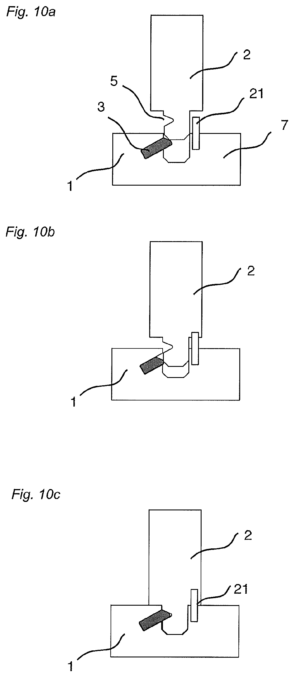
FIGS. 10a-10c illustrate embodiments of the invention.
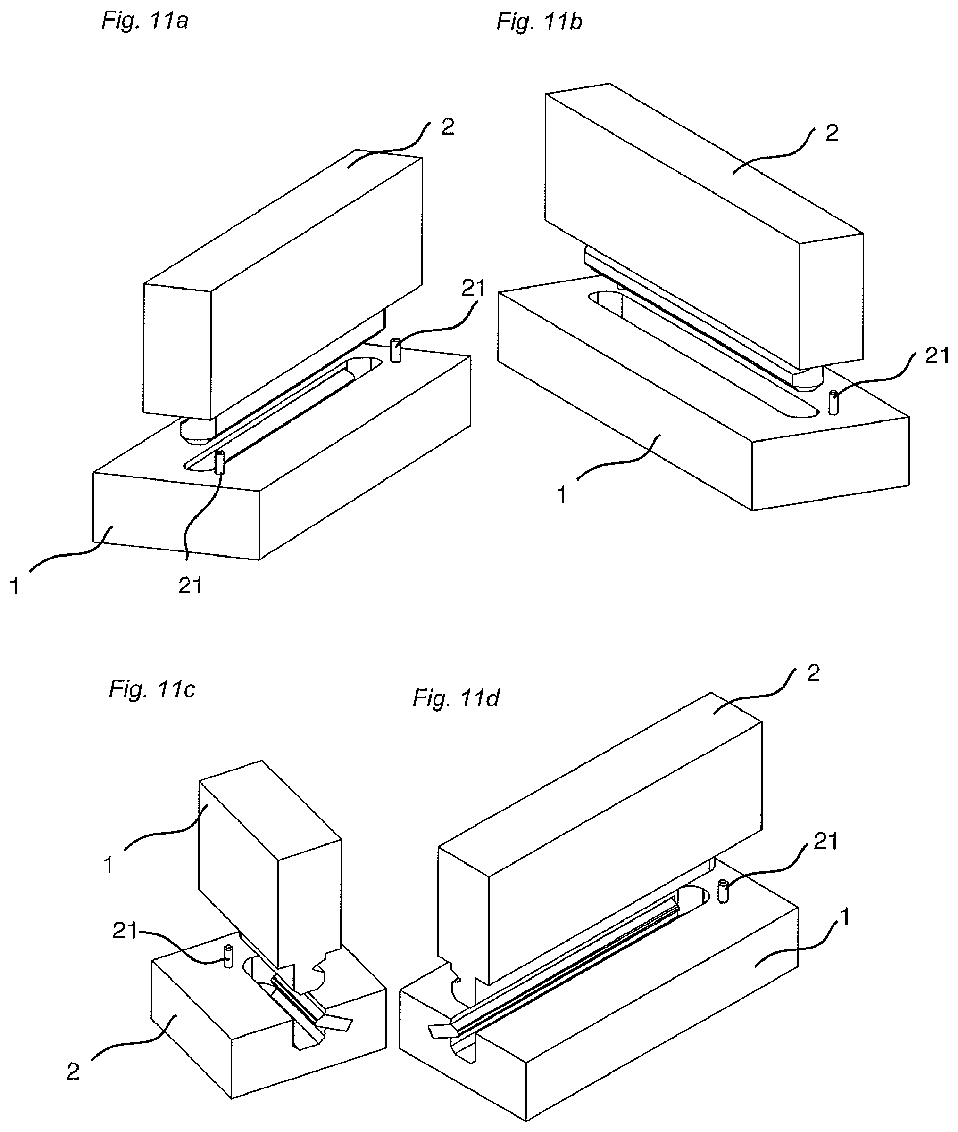
FIGS. 11a-11d illustrate embodiments of the invention in a 3d view.
DESCRIPTION OF EMBODIMENTS OF THE INVENTION
To facilitate understanding, several locking systems in the figures are shown schematically. It should be emphasized that improved or different functions can be achieved using combinations of the preferred embodiments.
FIGS. 1a-1c show a connection with a perpendicular snap action according to a preferred embodiment of the invention. FIG. 1a shows a first 1 and a second 2 panel. The first panel 1 comprises a groove 6, formed in the panel core 7. The groove comprises a bottom 6a and two opposite groove walls 6b, 6c. The groove is open towards a main plane MP of the first panel 1. An insertion groove 4 is formed in one of the groove walls 6b. The insertion groove 4 is preferably inclined in relation to the main plane MP of the panel such that the opening of the insertion groove 4a is closer to the main plane MP than the inner part 4b. It is preferred that a linear extension E of the insertion groove extends at or more preferably above the opening of the groove 6. This makes it possible to form the insertion groove with large rotating tools and to insert a separate tongue 3 into the groove. The insertion groove is preferably inclined with an angle A of about 10-45 degrees. The insertion groove comprises a flexible tongue 3, which has an inner part 9 and an outer part 10 and preferably two opposite sliding surfaces 3a and 3b between the inner 9 and the outer 10 parts.
FIG. 1b shows how the flexible tongue 3 with its displacement surfaces 3a, 3b is displaced inwardly into the insertion groove 4 when the second panel 2 is inserted into the groove 6 perpendicularly to the first panel 1.
FIG. 1c shows how the flexible tongue 3 is displaced in the insertion groove outwardly into the tongue groove 5 such that the second panel is connected perpendicular and parallel to the first panel with preferably a snap action. The flexible tongue and the tongue groove lock the panels perpendicularly to the main plane MP of the first panel 1. The groove 6 and the edge 16 of the second panel lock the panels parallel to the main plane MP of the first panel 1. The flexible tongue 3 may be locked with pre tension into the tongue groove 5.
FIGS. 2a and 2b show another preferred embodiment of the invention where the edge 15, of the first panel comprises a locking element 12 and the edge 16 of the second panel comprises a locking groove 14. The locking element and the locking groove locks the panels parallel to the main plane of the first panel. This embodiment may be used to connect corner sections. A tongue and a tongue groove 5a may also be located and formed on the outer part of the locking element 12 and/or in a groove wall of the locking groove 14 as shown in FIG. 2b. There may be a space between the outer part of the locking element 12 and the locking groove, or a play or a tight fit. The insertion groove 4 may be formed in the second panel and the tongue groove 5 in the first panel. The insertion groove and/or the locking surfaces between the flexible tongue and the tongue groove may be inclined or essentially parallel to the main plane MP of the first panel.
FIG. 2c shows an alternative embodiment, which may be used to connect corner sections or middle sections. The edge 15, of the first panel 1, comprises a locking element 12 that in locked position forms an outer free end of the panel. The flexible tongue 3 is displaced inwardly into the insertion groove 4 when the second panel 2 is inserted into the groove 6 perpendicularly to the first panel 1. The inclination of the insertion groove 4 facilitates the insertion of the flexible tongue 3 into the insertion groove 4 during production and locking may be accomplished with lower resistance since the flexible tongue 3 slides inwardly and downwardly during locking. The insertion groove is preferably inclined such that an extension E of its lower part is located at or above the upper part of the locking element 12.
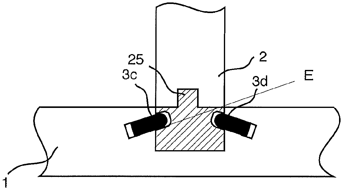
FIG. 2d shows that the second panel 2 may have an outer edge 26 with a smaller thickness than the panel body 2 such that the panel body 2 overlaps one 27 or both parts 27, 28 of the groove opening when the second panel 2 is inserted into the groove 6 of the first panel 1. The first and/or the second panel may comprise separate materials 24, 25 that form an edge or a groove portion of the first or the second panels. A particle board panel may for example be reinforced with solid wood, plywood, HDF and similar wood based materials that are glued or mechanically connected to the panel in order to form at least a part of the locking system. Separate materials may be covered with for example a foil, paper or paint.
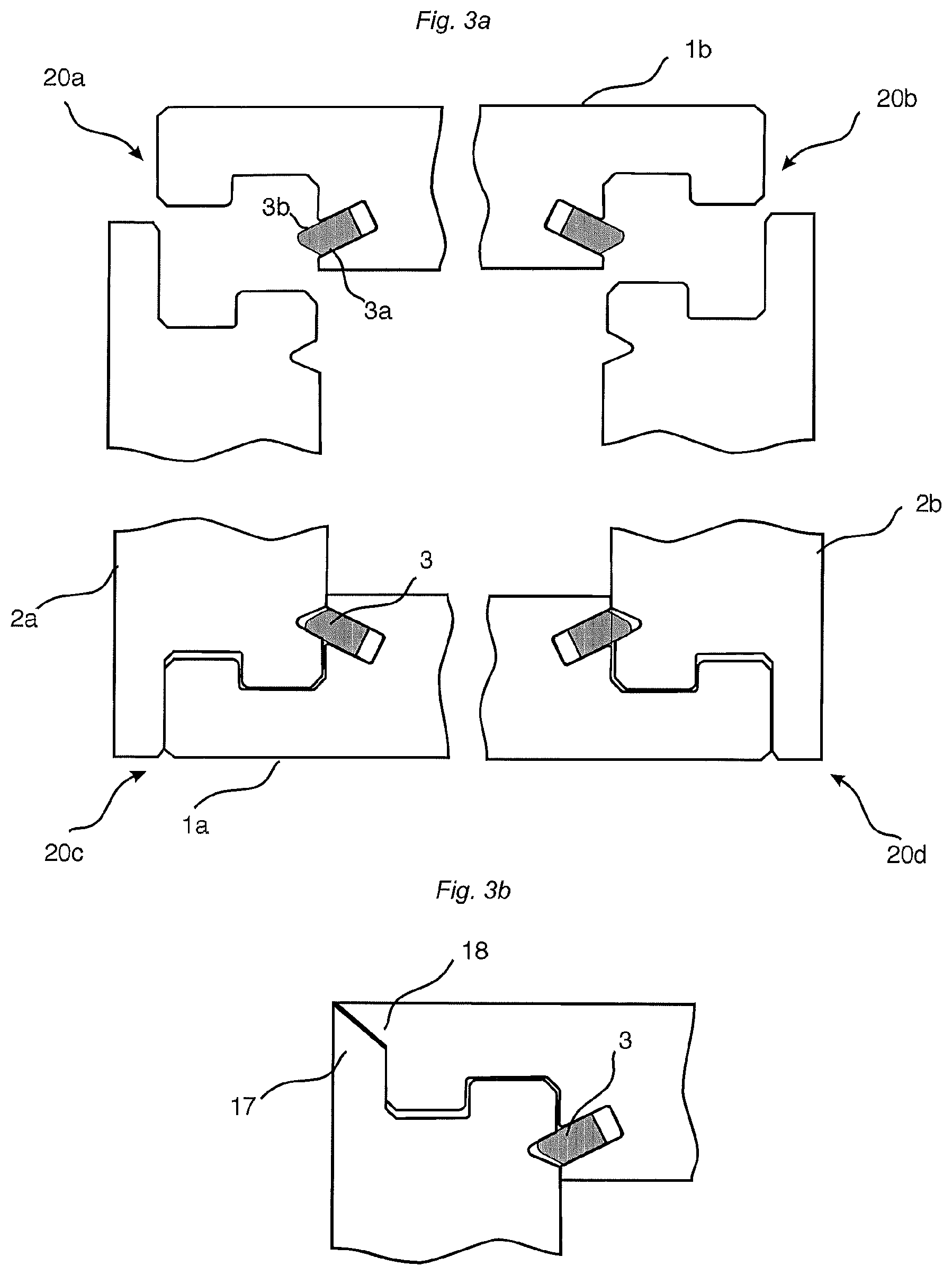
FIG. 3 shows a connection of four corner sections 20a, b, c, d. Four panels of for example a kitchen cabinet may be connected. A first panel 1a is placed on a floor. A second 2a and a third 2b panel are connected with snapping to the first panel 1a. Finally a fourth panel 1b is connected to the second and third panels.
FIG. 3b shows a corner section where the adjacent panel edges 17, 18 are inclined, preferably inwardly and preferably with an angle of about 45 degrees against the main plane of the panels.
FIGS. 4a-4c show a known flexible bristle tongue 3, which is used to connect floor panels. Such a tongue may be used to connect panels according to embodiments of the invention. The tongue comprises flexible protrusions 8 that bend in the length direction of the tongue and that displace the tongue in the insertion groove during the snap action. FIG. 4a shows the tongue in the outer position prior to locking, FIG. 4b shows the tongue 3 in the inner position during locking, and FIG. 4c shows the tongue 3 in the outer and locked position.
FIG. 4d shows a flexible bow shaped tongue 3 that bends in the length direction.
All known flexible tongues that are used to lock floor panels may be used in embodiments of this invention. Tongues that bend in the length direction are preferred, for example, bristle tongues and bow shaped tongues, as shown in FIGS. 4a and 4d, since such tongues have the advantage that flexibility may be combined with a rigid and strong outer part that creates a strong locking even in rather soft core materials such as particle boards that are generally used as a core in furniture components. It is an advantage if the tongue creates a pre tension against the tongue groove in locked position. This gives a stronger locking and eliminates production tolerances especially if the locking surface of the tongue/tongue groove is inclined against the main plane of the first panel. The tongue is preferably formed of an injection moulded plastic material preferably reinforced with glass fibres.
FIG. 5a shows an embodiment with two tongues 3c,3d. The edge of the second panel 2 may comprise a separate material 25.
FIG. 5b shows a tongue 3 that comprise an outer part 4 with a snap tab that during snapping is displaced at least partly into an inclined insertion groove 4. The locking system comprises a stabilizing tongue 11 that may be formed in one piece with the core or inserted as a separate element.
FIG. 5c shows a tongue 3 comprising a snap tab 10 that during snapping is displaced outside the insertion groove 4.
FIG. 6a shows a tongue that comprises an inner and outer flexible part. FIG. 6b shows an embodiment with a turning and snapping tongue 3 comprising a pressing arm 21 that turns and snaps the tongue 3 into a tongue groove.
FIG. 6c shows schematically that the insertion groove 4 may be formed in the second panel 2.
FIGS. 7a-7c show alternative positions of the flexible tongues. FIG. 7a shows that the second panel may be somewhat inclined for example 45-89 degrees against main plane of the first panel. FIG. 7b shows two tongues 3c, 3d attached to a middle section of a first panel 1 and FIG. 7c shows a corner section.
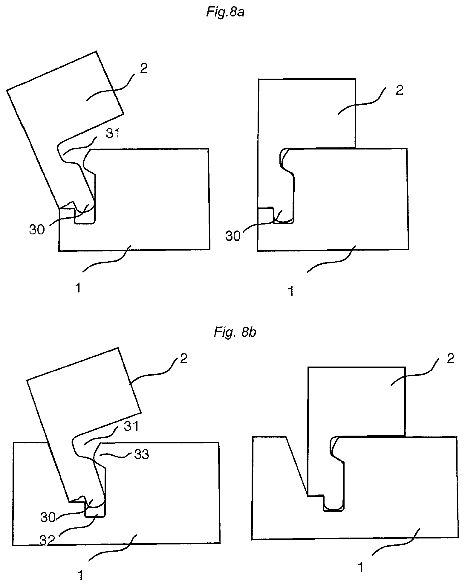
FIGS. 8a and 8b shows that two panels may be angled together according to the generally known principles used in locking systems for flooring. Such angling connection may be combined with all snapping embodiments described above. FIG. 8a shows an angling connection of a corner section and FIG. 8b shows an angling connection of a middle section. The second panel 2 that is angled during connection comprises a tongue 30 and a locking groove 31 that cooperates during locking with a tongue groove 32 and a locking element 33 formed in the first panel.
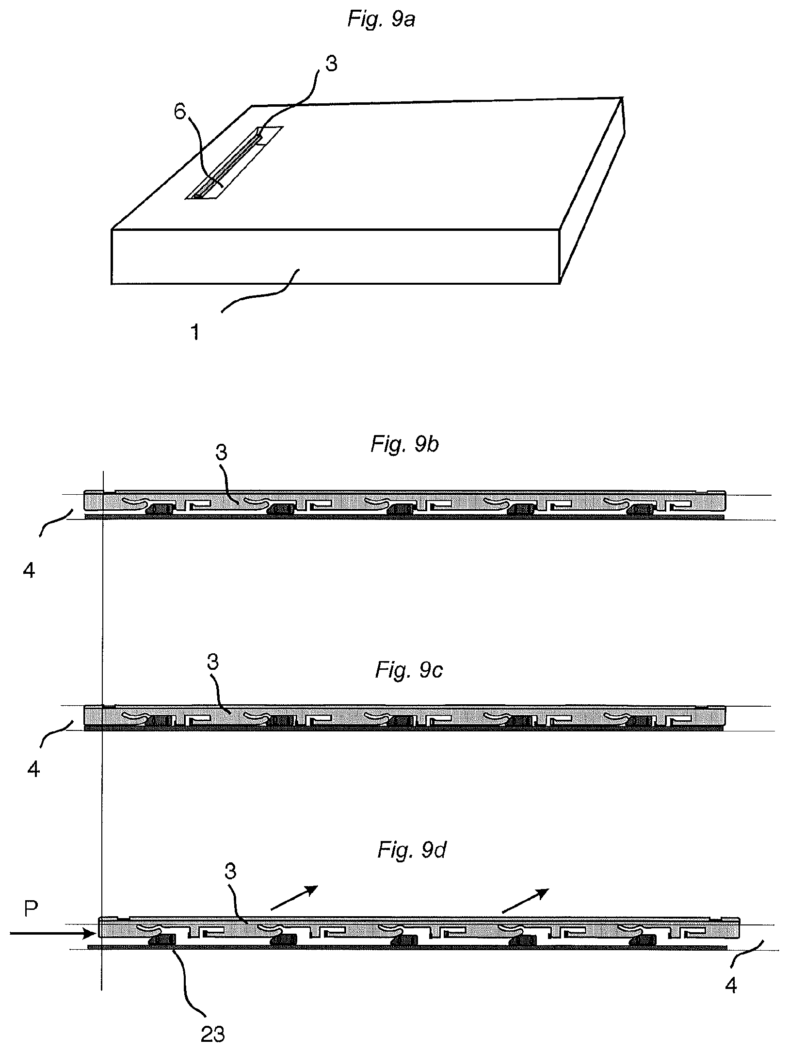
All fixation and tongue grooves may be formed over the complete length or with of a panel. They may also be formed as one or several local grooves, which only extend along a part of the panel. Such grooves may be formed in many ways for example with rotating jumping tool heads. Such a local groove 6 is schematically shown in FIG. 9a.
FIGS. 9b-9d show that the so-called side push locking systems may also be used to connect furniture components. Such a tongue 3 that is displaced width a side pressure P along the insertion groove 4 and perpendicularly to the insertion groove into the tongue groove may be used in all embodiments shown above. The perpendicular displacement may be accomplished with wedges 23 or with a fixation groove, which have a depth that varies along the groove. The tongue 3 and the tongue groove may also comprise overlapping protrusion and a locking may be accomplished with a displacement along the insertion groove without any perpendicular displacement into the tongue groove. Such embodiments allow locking with a rigid tongue and no flexible parts are needed.
FIGS. 10a-10c show an embodiment of the invention further comprising a plug 21 of e.g. plastic, wood or metal at of the panels 1, 2 inserted into a hole, preferably at the edge of the other panel, The plug and the hole increases the strength of the connection and may be used to position the panels.
FIG. 11a-11b show the embodiment in FIG. 10a-c in a 3d view at two different angles and FIG. 11c-11d a cross section in a 3d view at two different angles.
EMBODIMENTS OF THE INVENTION
1. A set of panels (1,2) comprising a first (1) and a second panel (2), an edge (16) of the second panel is insertable into a groove (6) of the first panel (1), when the panels are arranged essential perpendicular to each other, to obtain a mechanical connection between the first and the second panel, when the second panel is displaced essentially perpendicularly to the first panel, wherein: said edge (16) comprises a separate and flexible tongue (3) and said groove (6) comprises a tongue groove (5), or said edge (16) comprises a tongue groove (5) and said groove (6) comprises a separate and flexible tongue (3); the separate and flexible tongue (3) is insertable into the tongue groove (5) for connecting said panels to each other in a first direction, which is parallel to a main plane (MP) of the first panel; the edge (16) of the second panel is configured to cooperate with the groove (6) of the first panel for connecting said panels to each other in a second direction, which is parallel to a main plane (MP) of the second panel; the length direction of the separate and flexible tongue (3) extends parallel with said edge and/or groove; the groove (6) comprises an opening, two side walls (6b, 6c) and a bottom (6a); the separate and flexible tongue (3) is arranged in an insertion groove (4); the separate and flexible tongue has an inner part (9) mounted in the insertion groove (4) and an outer part (10) extending outside an opening of the insertion groove; and the flexible tongue is displaceable inwardly towards a bottom of the insertion groove (4) and outwardly into the tongue groove (5) during locking.
2. The set of panels as recited in embodiment 1, wherein the flexible tongue has two opposite displacement surfaces (3a, 3b) located between the inner and the outer parts, each of the two opposite displacement surfaces of the flexible tongue (3) are displaceable against an upper and a lower wall respectively of the insertion groove during locking, inwardly towards the bottom of the insertion groove (4) and outwardly into the tongue groove (5).
3. The set of panels as recited in embodiment 1 or 2, wherein the said insertion groove (4) is inclined upwards with the opening closer to the main plane (MP) of the panel than the inner part insertion groove (4).
4. The set of panels as recited in any of the preceding embodiments, wherein the insertion groove (4) is inclined such that an extension E of its lower part is located at or above the upper part of the opening of the groove (6).
5. The set of panels as recited in any of the preceding embodiments, wherein the second panel comprises an outer edge with a smaller thickness than the panel body (2) such that the panel body overlaps one or both parts of the groove (6) opening (27, 28) when the second panel (2) is inserted into the groove (6) of the first panel (1).
6. The set of panels as recited in any of the preceding embodiments, wherein the inner part of the tongue (9) comprises one or several flexible protrusions (8) extending in the length direction of the tongue (3).
7. The set of panels as recited in any of the preceding embodiments, wherein the insertion groove (4) is formed in the groove (6) of the first panel (1).
8. The set of panels as recited in any of the preceding embodiments, wherein the insertion groove (4) is inclined in relation to the main plane of the second panel with an angle of about 10-45 degrees.
9. The set of panels as recited in any of the preceding embodiments, wherein the panels comprises at least two flexible tongues separated from each other.
10. The set of panels as recited in any of the preceding embodiments, wherein the groove (6) is formed as a partial groove extending along a part of a panel.
11. The set of panels as recited in any of the preceding embodiments, wherein the panels are provided with a locking element (12) and a locking groove (14) for locking the panels parallel to the main plane (MP) of the first panel (1).
12. The set of panels as recited in any of the preceding embodiments, wherein adjacent outer panel edges (17,18) in a corner portion are inclined inwardly against the main plane (MP) of the panels.
13. The set of panels as recited in any of the preceding embodiments, wherein the tongue (3) is locked with pre tension against the tongue groove (5).
14. The set of panels as recited in any of the preceding embodiments, wherein the resilient parts are formed of an injection moulded plastic material.
15. The set of panels as recited in any of the preceding embodiments, wherein the first and/or the second panel comprise separate materials (24, 25) that form an edge or a groove portion.
16. The set of panels as recited in embodiment 15, wherein the separate material is covered with a foil.
* * * * *
D00000
D00001
D00002
D00003
D00004
D00005
D00006
D00007
D00008
D00009
D00010
D00011
XML
uspto.report is an independent third-party trademark research tool that is not affiliated, endorsed, or sponsored by the United States Patent and Trademark Office (USPTO) or any other governmental organization. The information provided by uspto.report is based on publicly available data at the time of writing and is intended for informational purposes only.
While we strive to provide accurate and up-to-date information, we do not guarantee the accuracy, completeness, reliability, or suitability of the information displayed on this site. The use of this site is at your own risk. Any reliance you place on such information is therefore strictly at your own risk.
All official trademark data, including owner information, should be verified by visiting the official USPTO website at www.uspto.gov. This site is not intended to replace professional legal advice and should not be used as a substitute for consulting with a legal professional who is knowledgeable about trademark law.