Furniture panel
Boo November 10, 2
U.S. patent number 10,830,268 [Application Number 14/573,572] was granted by the patent office on 2020-11-10 for furniture panel. This patent grant is currently assigned to VALINGE INNOVATION AB. The grantee listed for this patent is Valinge Innovation AB. Invention is credited to Christian Boo.
| United States Patent | 10,830,268 |
| Boo | November 10, 2020 |
Furniture panel
Abstract
A furniture panel is provided, in which a first element and a second element are mechanically locked together. A first tongue is provided at a first edge of the first element, the first tongue cooperating with a first tongue groove provided at a second edge of the second element for locking the first and second elements in a vertical direction, and a second tongue at the second edge of the second element, the second tongue cooperating with a second tongue groove at the first edge of the first element for locking the first and second elements in the vertical direction. A first pair of locking surfaces is provided above the second tongue and the second tongue groove for locking in a horizontal direction, and a second pair of locking surfaces is provided below the first tongue and the first tongue groove for locking in the horizontal direction.
| Inventors: | Boo; Christian (Kagerod, SE) | ||||||||||
|---|---|---|---|---|---|---|---|---|---|---|---|
| Applicant: |
|
||||||||||
| Assignee: | VALINGE INNOVATION AB (Viken,
CH) |
||||||||||
| Family ID: | 1000005172804 | ||||||||||
| Appl. No.: | 14/573,572 | ||||||||||
| Filed: | December 17, 2014 |
Prior Publication Data
| Document Identifier | Publication Date | |
|---|---|---|
| US 20150198191 A1 | Jul 16, 2015 | |
Foreign Application Priority Data
| Jan 10, 2014 [SE] | 1450018 | |||
| Current U.S. Class: | 1/1 |
| Current CPC Class: | F16B 12/46 (20130101); A47B 47/042 (20130101); Y10T 403/7073 (20150115); F16B 2012/466 (20130101); A47B 2088/902 (20170101) |
| Current International Class: | F16B 12/00 (20060101); F16B 12/46 (20060101); A47B 88/90 (20170101); A47B 47/04 (20060101) |
References Cited [Referenced By]
U.S. Patent Documents
| 291032 | January 1884 | Cleland |
| 634581 | October 1899 | Miller |
| 701000 | May 1902 | Ahrens |
| 861911 | July 1907 | Stewart |
| 881673 | March 1908 | Ellison |
| 1534468 | April 1925 | Shea, Jr. |
| 1954242 | April 1934 | Heppenstall |
| 2360451 | October 1944 | Stone |
| 2362904 | November 1944 | Kramer |
| 2496184 | January 1950 | Von Canon |
| 3195968 | July 1965 | Freeman |
| 3284152 | November 1966 | Schorghuber |
| 3347610 | October 1967 | Pilliod |
| 3410441 | November 1968 | Rhyne |
| 3722704 | March 1973 | Piretti |
| 3722971 | March 1973 | Zeischegg |
| 3784271 | January 1974 | Schreiber |
| 3885845 | May 1975 | Krieks |
| 4089614 | May 1978 | Harley |
| 4099887 | July 1978 | MacKenroth |
| 4116510 | September 1978 | Franco |
| 4142271 | March 1979 | Busse |
| 4279397 | July 1981 | Larsson |
| 4509648 | April 1985 | Govang |
| 4597122 | July 1986 | Handler et al. |
| 4750794 | June 1988 | Vegh |
| 4752150 | June 1988 | Salice |
| 4883331 | November 1989 | Mengel |
| 4886326 | December 1989 | Kuzyk |
| 4909581 | March 1990 | Haheeb |
| 5004116 | April 1991 | Cattarozzi |
| 5114265 | May 1992 | Grisley |
| 5209556 | May 1993 | Anderson |
| 5212925 | May 1993 | McClinton |
| 5360121 | November 1994 | Sothman |
| 5475960 | December 1995 | Lindal |
| 5499886 | March 1996 | Short et al. |
| 5527103 | June 1996 | Pittman |
| 5658086 | August 1997 | Brokaw et al. |
| 5893617 | April 1999 | Lee |
| 5950389 | September 1999 | Porter |
| 6413007 | July 2002 | Lambright |
| 6505452 | January 2003 | Hannig |
| 6675979 | January 2004 | Taylor |
| 6769219 | August 2004 | Schwitte |
| 6827028 | December 2004 | Callaway |
| 7451535 | November 2008 | Wells et al. |
| 7451578 | November 2008 | Hannig |
| 7584583 | September 2009 | Bergelin et al. |
| 7621092 | November 2009 | Groeke et al. |
| 7641414 | January 2010 | Joyce |
| 7721503 | May 2010 | Pervan |
| 7818939 | October 2010 | Bearinger |
| 7998549 | August 2011 | Susnjara |
| 8038363 | October 2011 | Hannig |
| 8042311 | October 2011 | Pervan |
| 8220217 | July 2012 | Muehlebach |
| 8365499 | February 2013 | Nilsson |
| 8387327 | March 2013 | Pervan |
| 8495849 | July 2013 | Pervan |
| 8505257 | August 2013 | Boo |
| 8544230 | October 2013 | Pervan |
| 8615952 | December 2013 | Engstrom |
| 8745952 | June 2014 | Perra |
| 8764137 | July 2014 | Fehre |
| 8833028 | September 2014 | Whispell |
| 8887468 | November 2014 | Hakansson et al. |
| 9175703 | November 2015 | Maertens |
| 9290948 | March 2016 | Cappelle |
| 9375085 | June 2016 | Derelov |
| 9538842 | January 2017 | Hakansson et al. |
| 9655442 | May 2017 | Boo et al. |
| 9714672 | July 2017 | Derelov et al. |
| 9723923 | August 2017 | Derelov |
| 9726210 | August 2017 | Derelov et al. |
| 9745756 | August 2017 | Hannig |
| 9758973 | September 2017 | Segaert |
| 9809983 | November 2017 | Trudel |
| 9945121 | April 2018 | Derelov |
| 10202996 | February 2019 | Hakansson et al. |
| 10415613 | September 2019 | Boo |
| 10448739 | October 2019 | Derelov et al. |
| 10451097 | October 2019 | Brannstrom et al. |
| 10669716 | June 2020 | Derelov et al. |
| 10670064 | June 2020 | Derelov et al. |
| 2006/0101769 | May 2006 | Pervan et al. |
| 2006/0236642 | October 2006 | Pervan |
| 2006/0273085 | December 2006 | Casto |
| 2007/0006543 | January 2007 | Engstrom |
| 2008/0066415 | March 2008 | Pervan |
| 2008/0216435 | September 2008 | Nolan |
| 2008/0236088 | October 2008 | Hannig et al. |
| 2009/0064624 | March 2009 | Sokol |
| 2010/0083603 | April 2010 | Goodwin |
| 2010/0173122 | July 2010 | Susnjara |
| 2010/0289389 | November 2010 | Crabtree, II |
| 2011/0225921 | September 2011 | Schulte |
| 2011/0225922 | September 2011 | Pervan et al. |
| 2011/0280655 | November 2011 | Maertens et al. |
| 2011/0283650 | November 2011 | Pervan et al. |
| 2012/0009383 | January 2012 | Hardesty |
| 2012/0027967 | February 2012 | Maertens et al. |
| 2012/0073235 | March 2012 | Hannig |
| 2012/0124932 | May 2012 | Schulte et al. |
| 2012/0145845 | June 2012 | Hightower |
| 2012/0180416 | July 2012 | Perra |
| 2012/0279161 | November 2012 | Hakansson et al. |
| 2012/0286637 | November 2012 | Fehre |
| 2013/0014463 | January 2013 | Pervan |
| 2013/0048632 | February 2013 | Chen |
| 2013/0071172 | March 2013 | Maertens et al. |
| 2013/0081349 | April 2013 | Pervan |
| 2013/0097846 | April 2013 | Pettigrew |
| 2013/0111845 | May 2013 | Pervan |
| 2013/0170904 | July 2013 | Cappelle et al. |
| 2013/0232905 | September 2013 | Pervan |
| 2014/0055018 | February 2014 | Shein et al. |
| 2014/0286701 | September 2014 | Sauer |
| 2015/0035422 | February 2015 | Hakansson et al. |
| 2015/0078807 | March 2015 | Brannstrom et al. |
| 2015/0078819 | March 2015 | Derelov et al. |
| 2015/0196118 | July 2015 | Derelov |
| 2015/0230600 | August 2015 | Schulte |
| 2015/0368896 | December 2015 | Schulte |
| 2016/0000220 | January 2016 | Devos |
| 2016/0007751 | January 2016 | Derelov |
| 2016/0145029 | May 2016 | Ranade et al. |
| 2016/0174704 | June 2016 | Boo et al. |
| 2016/0192775 | July 2016 | Andersson |
| 2016/0270531 | September 2016 | Derelov |
| 2017/0079433 | March 2017 | Derelov et al. |
| 2017/0089379 | March 2017 | Pervan |
| 2017/0097033 | April 2017 | Hakansson et al. |
| 2017/0159291 | June 2017 | Derelov |
| 2017/0208938 | July 2017 | Derelov et al. |
| 2017/0227031 | August 2017 | Boo |
| 2017/0227032 | August 2017 | Fridlund |
| 2017/0227035 | August 2017 | Fridlund |
| 2017/0234346 | August 2017 | Fridlund |
| 2017/0298973 | October 2017 | Derelov |
| 2017/0360193 | December 2017 | Boo |
| 2018/0080488 | March 2018 | Derelov |
| 2018/0087552 | March 2018 | Derelov et al. |
| 2018/0112695 | April 2018 | Boo et al. |
| 2018/0119717 | May 2018 | Derelov |
| 2018/0178406 | June 2018 | Fransson et al. |
| 2019/0113061 | April 2019 | Hakansson et al. |
| 2019/0166989 | June 2019 | Boo et al. |
| 2019/0289999 | September 2019 | Derelov et al. |
| 2019/0320793 | October 2019 | Boo |
| 2019/0323532 | October 2019 | Boo |
| 2019/0323533 | October 2019 | Boo |
| 2019/0323534 | October 2019 | Derelov |
| 2019/0323535 | October 2019 | Derelov |
| 2020/0003242 | January 2020 | Brannstrom et al. |
| 2020/0214447 | July 2020 | Derelov et al. |
| 685 276 | May 1995 | CH | |||
| 696 889 | Jan 2008 | CH | |||
| 698988 | Dec 2009 | CH | |||
| 203424576 | Feb 2014 | CN | |||
| 26 35 237 | Feb 1978 | DE | |||
| 20 2009 008 825 | Oct 2009 | DE | |||
| 10 2009 041 142 | Mar 2011 | DE | |||
| 10 2014 110 124 | Jan 2016 | DE | |||
| 0 362 968 | Apr 1990 | EP | |||
| 0 675 332 | Oct 1995 | EP | |||
| 0 871 156 | Oct 1998 | EP | |||
| 1 048 423 | Nov 2000 | EP | |||
| 1 048 423 | May 2005 | EP | |||
| 1 650 375 | Apr 2006 | EP | |||
| 1 671 562 | Jun 2006 | EP | |||
| 1 863 984 | Dec 2007 | EP | |||
| 1 922 954 | May 2008 | EP | |||
| 2 017 403 | Jan 2009 | EP | |||
| 2 037 128 | Mar 2009 | EP | |||
| 1 922 954 | Jul 2009 | EP | |||
| 2 333 353 | Jun 2011 | EP | |||
| 1 863 984 | Nov 2011 | EP | |||
| 3031998 | Jun 2016 | EP | |||
| 2 062 731 | Jun 1971 | FR | |||
| 2 517 187 | Jun 1983 | FR | |||
| 1 022 377 | Mar 1966 | GB | |||
| 2 482 213 | Jan 2012 | GB | |||
| 2003-239921 | Aug 2003 | JP | |||
| 10-1147274 | May 2012 | KR | |||
| 2014-0042314 | Apr 2014 | KR | |||
| WO 87/07339 | Dec 1987 | WO | |||
| WO 00/66856 | Nov 2000 | WO | |||
| WO 01/02669 | Jan 2001 | WO | |||
| WO 01/02670 | Jan 2001 | WO | |||
| WO 01/51733 | Jul 2001 | WO | |||
| WO 01/53628 | Jul 2001 | WO | |||
| WO 02/055809 | Jul 2002 | WO | |||
| WO 02/055810 | Jul 2002 | WO | |||
| WO 03/016654 | Feb 2003 | WO | |||
| WO 03/083234 | Oct 2003 | WO | |||
| WO 2004/079130 | Sep 2004 | WO | |||
| WO 2005/068747 | Jul 2005 | WO | |||
| WO 2006/043893 | Apr 2006 | WO | |||
| WO 2006/104436 | Oct 2006 | WO | |||
| WO 2007/015669 | Feb 2007 | WO | |||
| WO 2007/015669 | Feb 2007 | WO | |||
| WO 2007/079845 | Jul 2007 | WO | |||
| WO 2008/004960 | Jan 2008 | WO | |||
| WO 2008/004960 | Jan 2008 | WO | |||
| WO 2008/017281 | Feb 2008 | WO | |||
| WO 2008/017301 | Feb 2008 | WO | |||
| WO 2008/017301 | Feb 2008 | WO | |||
| WO 2008/150234 | Dec 2008 | WO | |||
| WO 2010/070472 | Jun 2010 | WO | |||
| WO 2010/070472 | Jun 2010 | WO | |||
| WO 2010/070605 | Jun 2010 | WO | |||
| WO 2010/070605 | Jun 2010 | WO | |||
| WO 2010/082171 | Jul 2010 | WO | |||
| WO 2010/087752 | Aug 2010 | WO | |||
| WO 2011/012104 | Feb 2011 | WO | |||
| WO 2011/012104 | Feb 2011 | WO | |||
| WO 2011/085710 | Jul 2011 | WO | |||
| WO 2011/151737 | Dec 2011 | WO | |||
| WO 2011/151737 | Dec 2011 | WO | |||
| WO 2011/151737 | Dec 2011 | WO | |||
| WO 2011/151758 | Dec 2011 | WO | |||
| WO 2011/151758 | Dec 2011 | WO | |||
| WO 2012/095454 | Jul 2012 | WO | |||
| WO 2012/154113 | Nov 2012 | WO | |||
| WO 2013/025163 | Feb 2013 | WO | |||
| WO 2013/080160 | Jun 2013 | WO | |||
| WO 2013/093636 | Jun 2013 | WO | |||
| WO 2013/093636 | Jun 2013 | WO | |||
| WO 2013/118075 | Aug 2013 | WO | |||
| WO 2014/108114 | Jul 2014 | WO | |||
| 2015/038059 | Mar 2015 | WO | |||
| WO 2015/105449 | Jul 2015 | WO | |||
| WO 2015/105450 | Jul 2015 | WO | |||
| WO 2015/105451 | Jul 2015 | WO | |||
Other References
|
US. Appl. No. 14/972,949, Christian Boo and Peter Derelov, filed Dec. 17, 2015. cited by applicant . Boo, Christian, et al., U.S. Appl. No. 14/972,949, entitled "Panels Comprising a Mechanical Locking Device and an Assembled Product Comprising the Panels," filed in the U.S. Patent and Trademark Office on Dec. 17, 2015. cited by applicant . International Search Report dated Apr. 22, 2015 in PCT/SE2014/051522, ISA/SE, Patent-och registreringsverket, Stockholm, SE, 5 pages. cited by applicant . Derelov, Peter, et al., U.S. Appl. No. 14/794,883, entitled "Panel With a Slider," filed in the U.S. Patent and Trademark Office on Jul. 9, 2015. cited by applicant . U.S. Appl. No. 14/158,165, Peter Derelov, Hans Brannstrom and Agne Palsson, filed Jan. 17, 2014. cited by applicant . U.S. Appl. No. 14/486,681, Hans Brannstrom, Agne Palsson and Peter Derelov, filed Sep. 15, 2014. cited by applicant . U.S. Appl. No. 14/515,988 (Cited herein as US Patent Application Publication No. US 2015/0035422 A1 of Feb. 5, 2015), Niclas Hakansson and Darko Pervan, filed Oct. 16, 2014. cited by applicant . U.S. Appl. No. 14/573,473, Peter Derelov, filed Dec. 17, 2014. cited by applicant . Derelov, Peter, et al., U.S. Appl. No. 14/158,165, entitled "Assembled Product and a Method of Assembling the Product," filed in the U.S. Patent and Trademark Office on Jan. 17, 2014. cited by applicant . Brannstrom, Hans, et al., U.S. Appl. No. 14/486,681, entitled "An Assembled Product and a Method of Assembling the Assembled Product," filed in the U.S. Patent and Trademark Office on Sep. 15, 2014. cited by applicant . Derelov, Peter, U.S. Appl. No. 14/573,473, entitled "Panels Comprising a Mechanical Locking Device and an Assembled Product Comprising the Panels," filed in the U.S. Patent and Trademark Office on Dec. 17, 2014. cited by applicant . U.S. Appl. No. 15/171,403, Peter Derelov, filed Jun. 2, 2016. cited by applicant . Derelov, Peter, U.S. Appl. No. 15/171,403 entitled "Panel with a Slider", filed in the U.S. Patent and Trademark Office on Jun. 2, 2016. cited by applicant . U.S. Appl. No. 15/271,622, Peter Derelov, filed Sep. 21, 2016. cited by applicant . U.S. Appl. No. 15/308,872, Darko Pervan, filed Nov. 4, 2016. cited by applicant . U.S. Appl. No. 15/366,704, Peter Derelov, filed Dec. 1, 2016. cited by applicant . U.S. Appl. No. 15/379,791, Niclas Hakansson, filed Dec. 15, 2016. cited by applicant . U.S. Appl. No. 15/415,356, Peter Derelov, filed Jan. 25, 2017. cited by applicant . U.S. Appl. No. 15/422,798, Magnus Fridlund, filed Feb. 2, 2017. cited by applicant . U.S. Appl. No. 15/428,469, Magnus Fridlund, filed Feb. 9, 2017. cited by applicant . U.S. Appl. No. 15/428,504, Christian Boo, filed Feb. 9, 2017. cited by applicant . U.S. Appl. No. 15/432,190, Magnus Fridlund, filed Feb. 14, 2017. cited by applicant . Derelov, Peter, et al., U.S. Appl. No. 15/271,622 entitled "Panels Comprising Mechanical Locking Device and an Assembled Product Comprising the Panels", filed in the U.S. Patent and Trademark Office on Sep. 21, 2016. cited by applicant . Pervan, Darko, U.S. Appl. No. 15/308,872 entitled "Mechanical Locking System for Building Panels," filed in the U.S. Patent and Trademark Office on Nov. 4, 2016. cited by applicant . Derelov, Peter, U.S. Appl. No. 15/366,704 entitled "Panels Comprising a Mechanical Locking Device and an Assembled Product Comprising the Panels", filed in the U.S. Patent and Trademark Office on Dec. 1, 2016. cited by applicant . Hakansson, Niclas, et al., U.S. Appl. No. 15/379,791 entitled "Mechanical Locking System for Building Panels," filed in the U.S. Patent and Trademark Office on Dec. 15, 2016. cited by applicant . Derelov, Peter, et al., U.S. Appl. No. 15/415,356 entitled "Panels Comprising a Mechanical Locking Device and an Assembled Product Comprising the Panels", filed in the U.S. Patent and Trademark Office on Jan. 25, 2017. cited by applicant . Fridlund, Magnus, U.S. Appl. No. 15/422,798 entitled "Set of Panels for an Assembled Product," filed in the U.S. Patent and Trademark Office on Feb. 2, 2017. cited by applicant . Fridlund, Magnus, U.S. Appl. No. 15/428,469 entitled "Element and Method for Providing Dismantling Groove," filed in the U.S. Patent and Trademark Office on Feb. 9, 2017. cited by applicant . Boo, Christian, U.S. Appl. No. 15/428,504 entitled "Set of Panel-Shaped Elements for a Composed Element," filed in the U.S. Patent and Trademark Office on Feb. 9, 2017. cited by applicant . Fridlund, Magnus, U.S. Appl. No. 15/432,190 entitled "Method for Forming a Panel," filed in the U.S. Patent and Trademark Office on Feb. 14, 2017. cited by applicant . Extended European Search issued in EP Patent Application No. 14878105.7, dated May 19, 2017, European Patent Office, Munich DE, 6 pages. cited by applicant . U.S. Appl. No. 15/584,633, Christian Boo, filed May 2, 2017. cited by applicant . U.S. Appl. No. 15/642,757, Peter Derelov, filed Jul. 6, 2017. cited by applicant . U.S. Appl. No. 15/646,714, Peter Derelov, filed Jul. 11, 2017. cited by applicant . Boo, Christian, et al., U.S. Appl. No. 15/584,633 entitled "Panels Comprising a Mechanical Locking Device and an Assembled Product Comprising the Panels", filed in the U.S. Patent and Trademark Office on May 2, 2017. cited by applicant . Derelov, Peter., U.S. Appl. No. 15/642,757 entitled "Panels Comprising a Mechanical Locking Device and an Assembled Product Comprising the Panels", filed in the U.S. Patent and Trademark Office on Jul. 6, 2017. cited by applicant . Derelov, Peter, et al., U.S. Appl. No. 15/646,714 entitled "Assembled Product and a Method of Assembling the Product", filed in the U.S. Patent and Trademark Office on Jul. 11, 2017. cited by applicant . U.S. Appl. No. 15/562,254, Peter Derelov, filed Sep. 27, 2017. cited by applicant . U.S. Appl. No. 15/567,507, Christian Boo, Peter Derelov and Agne Palsson, filed Oct. 18, 2017. cited by applicant . U.S. Appl. No. 15/794,491, Peter Derelov, filed Oct. 26, 2017. cited by applicant . U.S. Appl. No. 15/848,164, Jonas Fransson, Andreas Blomgren and Karl Erikson, filed Dec. 20, 2017. cited by applicant . Derelov, Peter, U.S. Appl. No. 15/562,254 entitled "Panel with a Slider", filed in the U.S. Patent and Trademark Office on Sep. 27, 2017. cited by applicant . Boo, Christian, et al., U.S. Appl. No. 15/567,507 entitled "Panel With a Fastening Device," filed in the U.S. Patent and Trademark Office on Oct. 18, 2017. cited by applicant . Derelov, Peter, U.S. Appl. No. 15/794,491 entitled "Set of Panels with a Mechanical Locking Device", filed in the U.S. Patent and Trademark Office on Oct. 26, 2017. cited by applicant . Fransson, Jonas, et al., U.S. Appl. No. 15/848,164 entitled "Device for Inserting a Tongue", filed in the U.S. Patent and Trademark Office on Dec. 20, 2017. cited by applicant . U.S. Appl. No. 15/923,701, Peter Derelov, filed Mar. 16, 2018. cited by applicant . Derelov, Peter, U.S. Appl. No. 15/923,701 entitled "Panels Comprising a Mechanical Locking Device and an Assembled Product Comprising the Panels", filed in the U.S. Patent and Trademark Office on Mar. 16, 2018. cited by applicant . U.S. Appl. No. 15/956,949, Peter Derelov, filed Apr. 19, 2018. cited by applicant . U.S. Appl. No. 15/978,630, Jonas Fransson, Niclas Hakansson and and Agne Palsson, filed May 14, 2018. cited by applicant . U.S. Appl. No. 16/027,479, Christian Boo and Peter Derelov, filed Jul. 5, 2018. cited by applicant . Derelov, Peter, U.S. Appl. No. 15/956,949 entitled "Panels for an Assembled Product", filed in the U.S. Patent and Trademark Office on Apr. 19, 2018. cited by applicant . Fransson, Jonas, et al., U.S. Appl. No. 15/978,630 entitled "Elements and a Locking Device for an Assembled Product," filed in the U.S. Patent and Trademark Office on May 14, 2018. cited by applicant . Boo, Christian, et al., U.S. Appl. No. 16/027,479 entitled "Panels Comprising a Mechanical Locking Device and an Assembled Product Comprising the Panels," filed in the U.S. Patent and Trademark Office on Jul. 5, 2018. cited by applicant . U.S. Appl. No. 16/220,574, Peter Derelov, filed Dec. 14, 2018. cited by applicant . U.S. Appl. No. 16/220,585, Peter Derelov, filed Dec. 14, 2018. cited by applicant . U.S. Appl. No. 16/228,975, Niclas Hakansson and Darko Pervan, filed Dec. 21, 2018. cited by applicant . Derelov, Peter, U.S. Appl. No. 16/220,574 entitled "Set of Panels," filed in the U.S. Patent and Trademark Office on Dec. 14, 2018. cited by applicant . Derelov, Peter, U.S. Appl. No. 16/220,585 entitled "Set of Panels," filed in the U.S. Patent and Trademark Office on Dec. 14, 2018. cited by applicant . Hakansson, Niclas, et al., U.S. Appl. No. 16/228,975 entitled "Mechanical Locking System for Building Panels," filed in the U.S. Patent and Trademark Office on Dec. 21, 2018. cited by applicant . Derelov, Peter, et al., U.S. Appl. No. 16/361,609 entitled "Panels Comprising a Mechanical Locking Device and an Assembled Product Comprising the Panels," filed in the U.S. Patent and Trademark Office on Mar. 22, 2019. cited by applicant . Boo, Christian, U.S. Appl. No. 16/386,732 entitled "Set of Panels With a Mechanical Locking Device," filed in the U.S. Patent and Trademark Office on Apr. 17, 2019. cited by applicant . Boo, Christian, U.S. Appl. No. 16/386,810 entitled "Set of Panels With a Mechanical Locking Device," filed in the U.S. Patent and Trademark Office on Apr. 17, 2019. cited by applicant . Boo, Christian, U.S. Appl. No. 16/386,824 entitled "Set of Panels With a Mechanical Locking Device," filed in the U.S. Patent and Trademark Office on Apr. 17, 2019. cited by applicant . Derelov, Peter, U.S. Appl. No. 16/386,874 entitled "Symmetric Tongue and T-Cross," filed in the U.S. Patent and Trademark Office on Apr. 17, 2019. cited by applicant . U.S. Appl. No. 16/553,325, Peter Derelov and Johan Svensson, filed Aug. 28, 2019. cited by applicant . U.S. Appl. No. 16/553,350, Peter Derelov and Johan Svensson, filed Aug. 28, 2019. cited by applicant . U.S. Appl. No. 16/564,438, Hans Brannstrom, Agne Palsson and Peter Derelov, filed Sep. 9, 2019. cited by applicant . U.S. Appl. No. 16/567,436, Peter Derelov and Mats Nilsson, filed Sep. 11, 2019. cited by applicant . U.S. Appl. No. 16/663,603, Magnus Fridlund, filed Oct. 25, 2019. cited by applicant . Derelov, Peter, U.S. Appl. No. 16/553,325 entitled "Set of Panels with a Mechanical Locking Device," filed in the U.S. Patent and Trademark Office on Aug. 28, 2019. cited by applicant . Derelov, Peter, U.S. Appl. No. 16/553,350 entitled "Set of Panels with a Mechanical Locking Device," filed in the U.S. Patent and Trademark Office on Aug. 28, 2019. cited by applicant . Brannstrom, Hans, et al., U.S. Appl. No. 16/564,438 entitled "Assembled Product and a Method of Assembling the Assembled Product," filed in the U.S. Patent and Trademark Office on Sep. 9, 2019. cited by applicant . Derelov, Peter, U.S. Appl. No. 16/567,436 entitled "Panels Comprising a Mechanical Locking Device and an Assembled Product Comprising the Panels," filed in the U.S. Patent and Trademark Office on Sep. 11, 2019. cited by applicant . Fridlund, Magnus, U.S. Appl. No. 16/663,603 entitled "Element and Method for Providing Dismantling Groove," filed in the U.S. Patent and Trademark Office on Oct. 25, 2019. cited by applicant . Boo, Christian, et al., U.S. Appl. No. 16/697,335 entitled "Panels Comprising a Mechanical Locking Device and an Assembled Product Comprising the Panels," filed in the U.S. Patent and Trademark Office on Nov. 27, 2019. cited by applicant . Fridlund, Magnus, U.S. Appl. No. 16/703,077 entitled "Set of Panels for an Assembled Product," filed in the U.S. Patent and Trademark Office Dec. 4, 2019. cited by applicant . Derelov, Peter, et al., U.S. Appl. No. 16/722,096 entitled "Panels Comprising a Mechanical Locking Device and an Assembled Product Comprising the Panels," filed in the U.S. Patent and Trademark Office on Dec. 20, 2019. cited by applicant . **Derelov, Peter, U.S. Appl. No. 16/861,639 entitled "Panels Comprising a Mechanical Locking Device and an Assembled Product Comprising the Panels," filed in the U.S. Patent and Trademark Office dated Apr. 29, 2020. cited by applicant . **Pervan, Darko, U.S. Appl. No. 16/946,047 entitled "Mechanical Locking System for Building Panels," filed in the U.S. Patent and Trademark Office dated Jun. 4, 2020. cited by applicant . **Brannstrom, Hans, et al., U.S. Appl. No. 16/915,258 entitled "Assembled Product and Method of Assembling the Assembled Product," filed in the U.S. Patent and Trademark Office dated Jun. 29, 2020. cited by applicant. |
Primary Examiner: McMahon; Matthew R
Attorney, Agent or Firm: Buchanan Ingersoll & Rooney P.C.
Claims
The invention claimed is:
1. A furniture panel comprising a first element and a second element which are configured to be locked together, wherein a first main plane of the first element is essentially parallel to a second main plane of the second element when the first element and the second element are locked together, wherein the furniture panel comprises a first face and an opposite second face which are parallel to a main plane of the furniture panel when the first element and the second element are locked together, and the first element and the second element are provided with a mechanical locking system, the mechanical locking system comprising: a first tongue provided at a first edge of the first element, wherein the first tongue is configured to cooperate with a first tongue groove provided at a second edge of the second element for locking together the first element and the second element in a first direction perpendicular to the main plane of the furniture panel, at least a portion of the first tongue groove being spaced from the second face by a first lip extending from the second element along a second direction parallel to the main plane of the furniture panel; a second tongue at the second edge of the second element, wherein the second tongue is configured to cooperate with a second tongue groove at the first edge of the first element for locking together the first element and the second element in the first direction, at least a portion of the second tongue groove being spaced from the first face by a second lip extending from the first element along the second direction; a first pair of locking surfaces provided between (a) the second tongue and the second tongue groove and (b) the first face for locking together the first element and the second element in the second direction; and a second pair of locking surfaces provided between (a) the first tongue and the first tongue groove and (b) the second face for locking together the first element and the second element in the second direction, wherein the second pair of locking surfaces is offset in the second direction from the first pair of locking surfaces.
2. The furniture panel as claimed in claim 1, wherein the first pair of locking surfaces extends essentially in the first direction.
3. The furniture panel as claimed in claim 1, wherein the second pair of locking surfaces extends essentially in the first direction.
4. The furniture panel as claimed in claim 1, wherein the first tongue and the first tongue groove cooperate at a third pair of locking surfaces that is arranged essentially in the second direction.
5. The furniture panel as claimed in claim 4, wherein the second tongue and the second tongue groove cooperate at a fourth pair of locking surfaces that is arranged at an angle greater than zero relative to an imaginary line extending in the second direction.
6. The furniture panel as claimed in claim 5, wherein the locking surfaces of the fourth pair contact each other along a contact portion extending at the angle greater than zero relative to the imaginary line extending in the second direction.
7. The furniture panel as claimed in claim 5, wherein a gap is provided between the first pair of locking surfaces and the second tongue when the first element and the second element are locked together.
8. The furniture panel as claimed in claim 7, wherein a second gap is provided between the first tongue and the second pair of locking surfaces when the first element and the second element are locked together.
9. The furniture panel as claimed in claim 8, wherein the first direction is vertical and the second direction is horizontal.
10. The furniture panel as claimed in claim 1, wherein the second tongue and the second tongue groove cooperate at a fourth pair of locking surfaces that is arranged at an angle greater than zero relative to an imaginary line extending in the second direction.
11. The furniture panel as claimed in claim 10, wherein the angle is configured so that the first element is locked to the second element by an angling motion of the first element relative to the second element or of the second element relative to the first element, wherein the first tongue is inserted in the first tongue groove.
12. The furniture panel as claimed in claim 10, wherein the angle is in a range of about 30.degree. to about 60.degree..
13. The furniture panel as claimed in claim 10, wherein the locking surfaces of the fourth pair contact each other along a contact portion extending at the angle greater than zero relative to the imaginary line extending in the second direction.
14. The furniture panel as claimed in claim 1, wherein a first space is provided in the first tongue groove between the first tongue and the first face in a locked state of the first element and the second element.
15. The furniture panel as claimed in claim 1, wherein a space is provided in the second tongue groove between the second tongue and the second face in a locked state of the first element and the second element.
16. The furniture panel as claimed in claim 1, wherein a core material of the first element and the second element comprises a wood fibre based board that is at least one of HDF, MDF, plywood, solid wood or particleboard, a plastic board and a wood fibre composite board.
17. The furniture panel as claimed in claim 1, wherein the second element includes a protruding element at a distal end of the second edge, and a strip extending between the protruding element and the first tongue groove, the strip including a recess adjacent the protruding element.
18. The furniture panel as claimed in claim 1, wherein a gap is provided between the first pair of locking surfaces and the second tongue when the first element and the second element are locked together.
19. The furniture panel as claimed in claim 1, wherein a gap is provided between the first tongue and the second pair of locking surfaces when the first element and the second element are locked together.
20. The furniture panel as claimed in claim 1, wherein the first direction is vertical and the second direction is horizontal.
21. A furniture panel comprising a first element and a second element which are configured to be locked together, wherein a first main plane of the first element is essentially parallel to a second main plane of the second element when the first element and the second element are locked together, wherein the furniture panel comprises a first face and an opposite second face which are parallel to a main plane of the furniture panel when the first element and the second element are locked together, and the first element and the second element are provided with a mechanical locking system, the mechanical locking system comprising: a first tongue provided at a first edge of the first element, wherein the first tongue is configured to cooperate with a first tongue groove provided at a second edge of the second element for locking together the first element and the second element in a first direction perpendicular to the main plane of the furniture panel; a second tongue at the second edge of the second element, wherein the second tongue is configured to cooperate with a second tongue groove at the first edge of the first element for locking together the first element and the second element in the first direction; a first pair of locking surfaces provided between (a) the second tongue and the second tongue groove and (b) the first face for locking together the first element and the second element in a second direction parallel to the main plane of the furniture panel; and a second pair of locking surfaces provided between (a) the first tongue and the first tongue groove and (b) the second face for locking together the first element and the second element in the second direction, wherein the second pair of locking surfaces is offset in the second direction from the first pair of locking surfaces, wherein, in the second direction, the first pair of locking surfaces and the second pair of locking surfaces are located between an outermost extent of the first tongue and an outermost extent of the second tongue.
Description
CROSS REFERENCE TO RELATED APPLICATIONS
The present application claims the benefit of Swedish Application No. 1450018-5, filed on Jan. 10, 2014. The entire contents of each of U.S. application Ser. No. 14/158,165 and Swedish Application No. 1450022-7 are hereby incorporated herein by reference in their entirety.
TECHNICAL FIELD
The present disclosure relates to a furniture panel, such as a back panel or a bottom panel, comprising a first element and a second element. The present disclosure also relates to an assembled product, such as a bookshelf, a cupboard, a wardrobe, a box, a drawer or a furniture component, comprising the furniture panel.
BACKGROUND
A furniture panel, such as a back panel or bottom panel, comprising a first element and a second element is known. The first element and the second element of the known furniture panel may be fixed by nailing the first element and the second element to a frame of an assembled product.
SUMMARY
One object of certain embodiments of the present disclosure is to provide an improvement over the above described technique and the known art. A specific objective is to improve the strength of a furniture panel, such as a back panel or bottom panel, comprising a first element and a second element. Another objective is to decrease the package size of a so-called flat-pack furniture. The back panel or the bottom panel of a flat-pack furniture may be the largest panel of the furniture compared to other panels of the furniture. A large furniture panel divided into two or more separate elements that can be mechanically locked together to form the large panel may therefore decrease the package size of the flat-pack furniture.
A further object of the present disclosure is to provide an assembled product with increased strength and stability.
At least some of these and other objects and advantages that will be apparent from the description have been achieved by a furniture panel comprising a first element and a second element which are configured to be locked together. A first main plane of the first element is essentially parallel to a second main plane of the second element when the first element and the second element are locked together. Essentially parallel meaning that the first element is arranged at an angle of 0.degree..+-.10.degree. to the second element, including being arranged parallel. The furniture panel comprises a first face and an opposite second face which are parallel to a main plane of the furniture panel when the first element and the second element are locked together. The first element and the second element is provided with a mechanical locking system comprising: a first tongue provided at a first edge of the first element, wherein the first tongue is configured to cooperate with a first tongue groove provided at a second edge of the second element for locking together the first element and the second element in a vertical direction perpendicular to the main plane of the furniture panel; a second tongue at the second edge of the second element, wherein the second tongue is configured to cooperate with a second tongue groove at the first edge of the first element for locking together the first element and the second element in the vertical direction; a first pair of locking surfaces provided above the second tongue and the second tongue groove for locking together the first element and the second element in a horizontal direction parallel to the main plane of the furniture panel; and second pair of locking surfaces provided below the first tongue and the first tongue groove for locking together the first element and the second element in the horizontal direction.
The mechanical locking system may provide a furniture panel with a joint between the first element and the second element that is hard to detect at the first face and the second face of the furniture panel. Further, the first tongue and the second tongue and the first tongue groove and the second tongue groove may provide a connection in the furniture panel that is essentially planar at the joint between the first element and the second element.
The first pair of locking surfaces is preferably essentially vertical and the second pair of locking surfaces is also preferably essentially vertical. Essentially vertical meaning that locking surfaces are vertical .+-.10.degree., including being vertical.
The first tongue and the first tongue groove may cooperate at a third pair of locking surfaces that is preferably arranged essentially horizontally. Essentially horizontal meaning that locking surfaces are horizontal .+-.10.degree., including being horizontal.
The second tongue and the second tongue groove may cooperate at a fourth pair of locking surfaces that is preferably arranged at an angle to the main plane of the furniture panel that is greater than zero. The angle preferably allows the first element to be locked to the second element by an angling motion of the first element relative to the second element or of the second element relative to the first element, wherein the first tongue is inserted in the first tongue groove. The angle may be in the range of about 30.degree. to about 60.degree., and is preferably about 45.degree..
A first space may be provided in the first tongue groove above the first tongue in a locked state of the first element and the second element. A second space may be provided in the second tongue groove under the second tongue in a locked state of the first element and the second element.
The second element includes a strip extending between the protruding element and the first tongue groove, and the strip includes a recess adjacent the protruding element.
A gap may be provided below the first pair of locking surfaces and above the second tongue when the first element and the second element are locked together. In addition, a gap may be provided below the first tongue and above the second pair of locking surfaces when the first element and the second element are locked together.
A core material of the first element and the second element preferably comprises a wood fibre based board, such as a HDF, MDF, plywood, solid wood or particleboard, a plastic board, or a wood plastic board.
The mechanical locking system is preferably made by mechanical cutting, such as milling, of the first edge of the first element and the second edge of the second element.
A second aspect of the present disclosure is an assembled product, such as a furniture component, comprising the furniture panel described above. The assembled product is preferably configured to be assembled without tools.
BRIEF DESCRIPTION OF THE DRAWINGS
Embodiments of the present disclosure will by way of example be described in more detail with reference to the appended schematic drawings, in which:
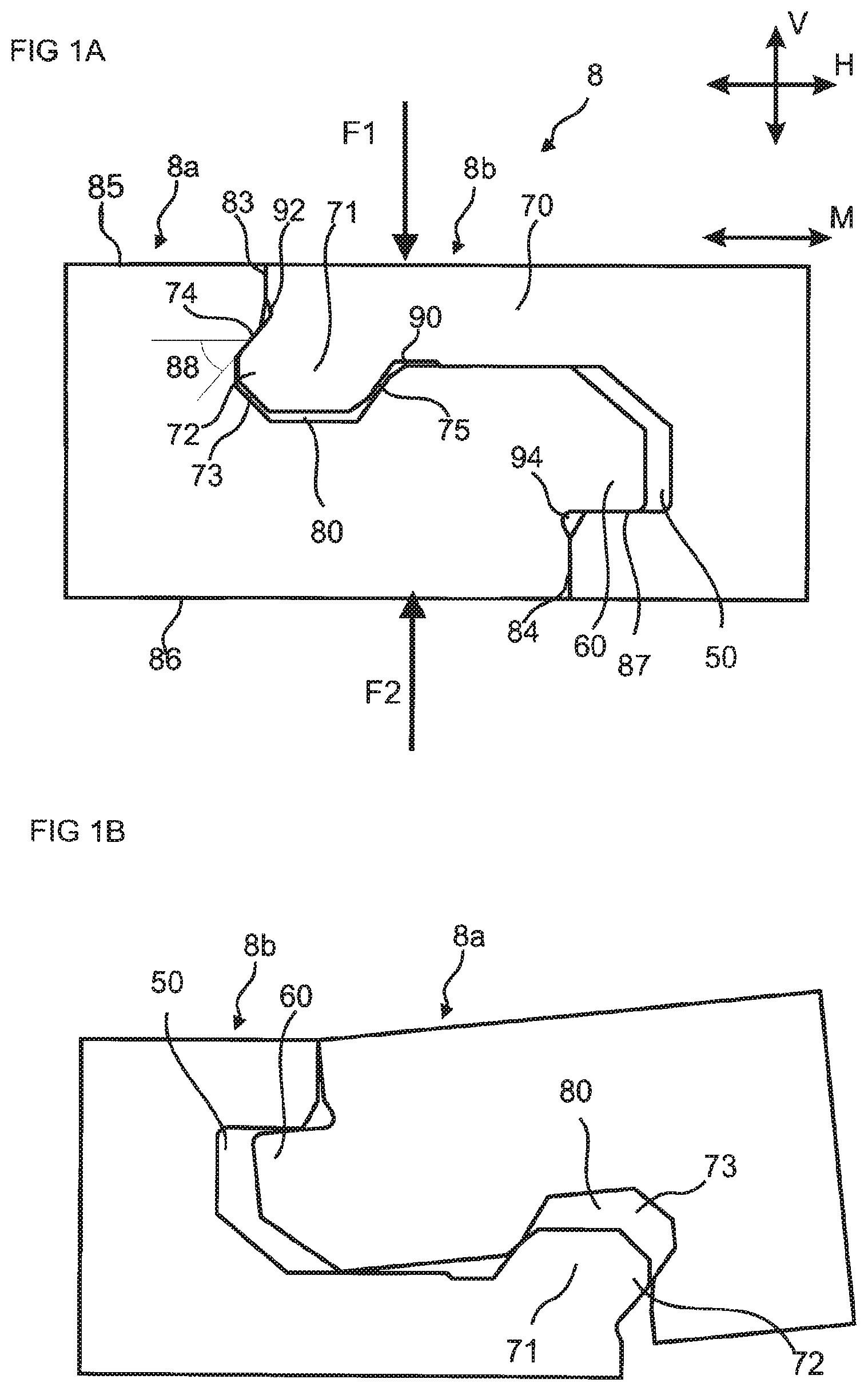
FIG. 1A shows a furniture panel according to an embodiment of the disclosure.
FIG. 1B shows the furniture panel according to an embodiment of the disclosure.
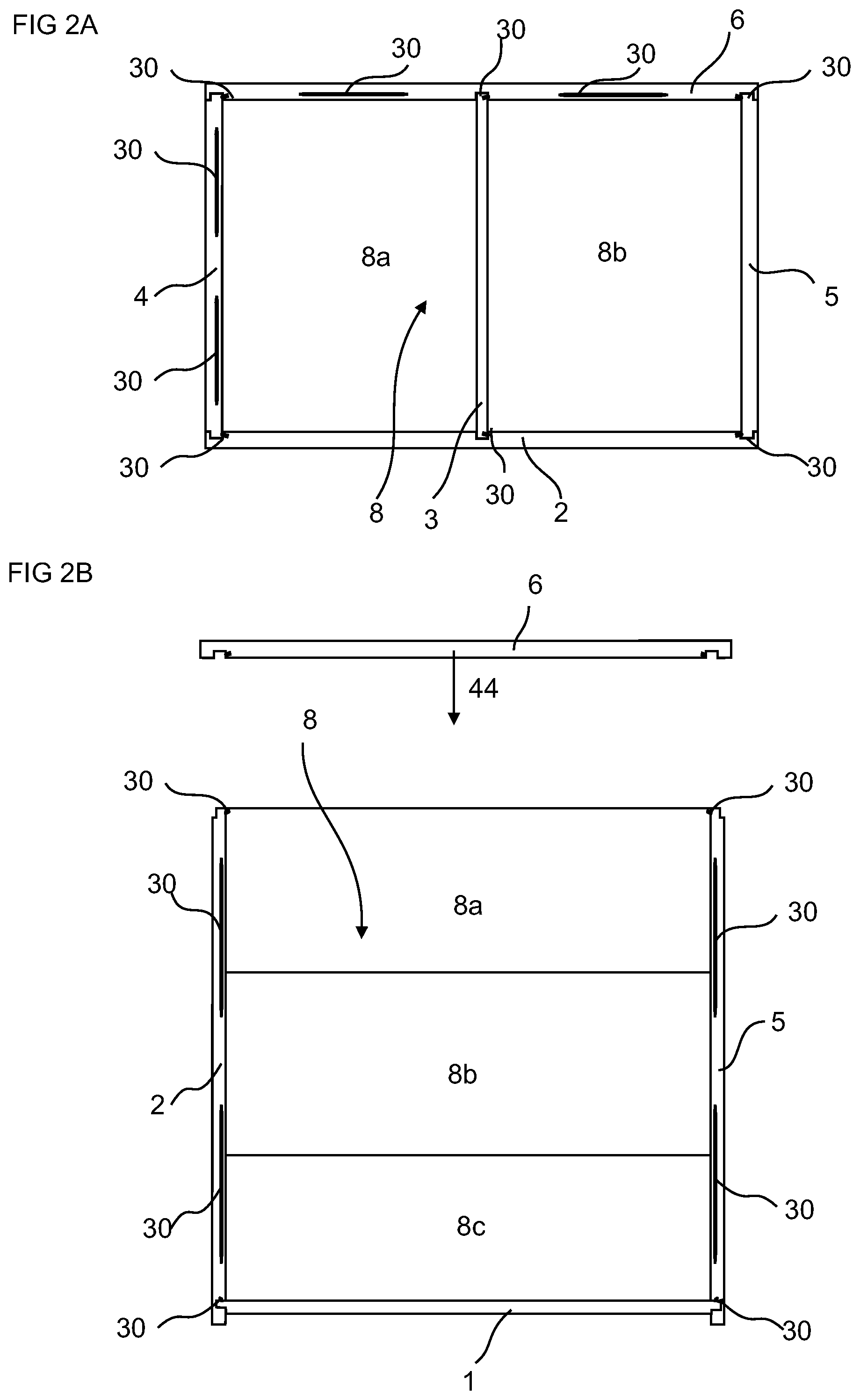
FIG. 2A shows an embodiment of a furniture component comprising a furniture panel according to an embodiment of the disclosure.
FIG. 2B shows an embodiment of a furniture component comprising the furniture panel according to an embodiment of the disclosure.
DETAILED DESCRIPTION
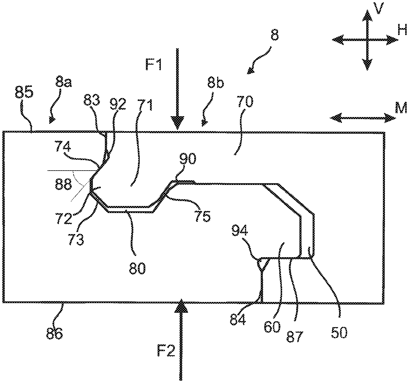
FIG. 1A shows an embodiment of a furniture panel 8, such as a back panel or bottom panel. The furniture panel 8 comprises a first element 8a and a second element 8b which are configured to be locked together. A first main plane of the first element is essentially parallel to a second main plane of the second element when the first element 8a and the second element 8b are locked together. The furniture panel 8 comprises a first face 85 and an opposite second face 86 which are parallel to a main plane M of the furniture panel 8 when the first element 8a and the second element 8b are locked together. The first element and the second element are provided with a mechanical locking system comprising: a first tongue 60 provided at a first edge of the first element 8a, wherein the first tongue 60 is configured to cooperate with a first tongue groove 50 provided at a second edge of the second element 8b for locking together the first element 8a and the second element 8b in a vertical direction V; a second tongue 72 at the second edge of the second element 8b, wherein the second tongue 72 is configured to cooperate with a second tongue groove 73 at the first edge of the first panel 8a for locking together the first element 8a and the second element 8b in the vertical direction V; a first pair of locking surfaces 83 provided above the second tongue 72 and the second tongue groove 73 for locking together the first element 8a and the second element 8b in a horizontal direction H parallel to the main plane M of the furniture panel 8; and second pair of locking surfaces 84 provided below the first tongue 60 and the first tongue groove 50 for locking together the first element 8a and the second element 8b in the horizontal direction H.
The mechanical locking system is preferably made by mechanical cutting, such as milling, of the first edge of the first element 8a and the second edge of the second element 8b.
The first pair of locking surfaces 83 is preferably essentially vertical. The second pair of locking surfaces 84 is also preferably essentially vertical.
The first tongue 60 and the first tongue groove 50 cooperate at a third pair of locking surfaces 87 that is preferably arranged essentially horizontally.
The second tongue 72 and the second tongue groove 73 cooperate at a fourth pair of locking surfaces 74 that is preferably arranged at an angle 88 to the main plane M of the furniture panel 8 that is greater than zero. The angle 88 has a range that allows the first element 8a to be locked to the second element 8b by an angling motion of the first element 8a relative to the second element 8b or of the second element 8b relative to the first element 8a, wherein the first tongue 60 is inserted in the first tongue groove 50. An embodiment of the angling motion of the first element 8a relative to the second element 8b is shown in FIG. 1B.
The first face 85 is arranged upwards in the vertical direction, e.g., in the direction were the greatest load F1 is likely to be exerted on the furniture panel 8, to prevent the first element 8a and the second element 8b from being unlocked by a reversed angling motion.
The second face 86 is arranged downwards in the vertical direction, e.g., in the direction where the smallest load F2 is likely to be applied on the furniture panel 8. The second tongue 72 and the second tongue groove 73 may provide a resistance for unlocking of the first element 8a and the second element 8b by a reversed angling motion.
The angle 88 may be in the range of about 30.degree. to about 60.degree.. The angle is preferably about 45.degree..
A first space may be provided in the first tongue groove 50 above the first tongue 60 in a locked state of the first element 8a and the second element 8b. A second space may be provided in the second tongue groove 73 under the second tongue 72 in a locked state of the first element 8a and the second element 8b.
The second edge of the second element 8b may be provided with a protruding element 71 that essentially matches a third groove 80 provided at the first edge of the first element 8a. The protruding element 71 may protrude upwards in the vertical direction V and the groove 80 may be open downwards in the vertical direction V. A third space 75, that extends in the horizontal direction H, may be provided between the protruding element 73 and the third groove 80. The third space 75 may facilitate the locking by an angling motion.
The second element 8b includes a strip 70 extending between the protruding element 71 and the first tongue groove 50. The strip 70 may include a recess 90 adjacent the protruding element 71. The recess 90 may provide the protruding element 71 with flexibility during locking of the first element 8a with the second element 8b.
In some embodiments, a gap 92 is provided below the first pair of locking surfaces 83 and above the second tongue 72 when the first element 8a and the second element 8b are locked together. In addition, a gap 94 may be provided below the first tongue 60 and above the second pair of locking surfaces 84 when the first element 8a and the second element 8b are locked together.
A core material of the first element 8a and the second element 8b in the various embodiments above preferably comprises a wood fibre based board, such as a HDF, MDF, plywood, solid wood or particleboard, a plastic board, or a wood fibre composite board.
FIGS. 2A-2B show embodiments of an assembled product, such as a furniture component, comprising embodiments of the furniture panel 8 disclosed above. FIG. 2A shows an embodiment of the assembled product, such as a cupboard. The assembled product includes a frame formed by perimeter panels 2, 4, 5, 6, and the first element 8a and the second element 8b serving as a back furniture panel 8. The assembled product may also include a divider panel 3. Edges of the panels 2, 3, 4, 5, 6 may be locked together as shown in FIG. 2A with a mechanical device comprising a flexible tongue 30.
FIG. 2B shows an embodiment comprising a third element 8c, which is connected to the second element 8b with the mechanical locking system discussed above. This assembled product is in the form of a drawer, with end panels 1 and 6 serving as back and front ends of the drawer, respectively. The mechanical device may comprising the flexible tongue 30 may facilitate an assembling of the assembled product without the use of tools and/or binding agents such as glue. For instance, end panel 6 is moved into engagement with a partially assembled product in the direction of arrow 44 so that the flexible tongue 30 engages with other parts of the mechanical device to effectuate locking.
Edges of the furniture panel may be inserted into grooves at bottom edges of the perimeter panels. The furniture panel is preferably locked to at least two of the perimeter panels by a mechanical device comprising a flexible tongue 30. Examples of such locking may be found in U.S. application Ser. No. 14/486,681, which is hereby incorporated by reference in its entirety.
When the word "about" is used in this specification in connection with a numerical value, it is intended that the associated numerical value include a tolerance of +/-10% around the stated numerical value.
* * * * *
D00000
D00001
D00002
XML
uspto.report is an independent third-party trademark research tool that is not affiliated, endorsed, or sponsored by the United States Patent and Trademark Office (USPTO) or any other governmental organization. The information provided by uspto.report is based on publicly available data at the time of writing and is intended for informational purposes only.
While we strive to provide accurate and up-to-date information, we do not guarantee the accuracy, completeness, reliability, or suitability of the information displayed on this site. The use of this site is at your own risk. Any reliance you place on such information is therefore strictly at your own risk.
All official trademark data, including owner information, should be verified by visiting the official USPTO website at www.uspto.gov. This site is not intended to replace professional legal advice and should not be used as a substitute for consulting with a legal professional who is knowledgeable about trademark law.