Radio module
Horn December 8, 2
U.S. patent number D904,355 [Application Number D/662,782] was granted by the patent office on 2020-12-08 for radio module. This patent grant is currently assigned to Gemalto M2M GmbH. The grantee listed for this patent is Gemalto M2M GmbH. Invention is credited to Annette Horn.


View All Diagrams
| United States Patent | D904,355 |
| Horn | December 8, 2020 |
Radio module
Claims
CLAIM The ornamental design for a radio module, substantially as shown and described.
| Inventors: | Horn; Annette (Berlin, DE) | ||||||||||
|---|---|---|---|---|---|---|---|---|---|---|---|
| Applicant: |
|
||||||||||
| Assignee: | Gemalto M2M GmbH (Berlin,
DE) |
||||||||||
| Appl. No.: | D/662,782 | ||||||||||
| Filed: | September 7, 2018 |
Related U.S. Patent Documents
| Application Number | Filing Date | Patent Number | Issue Date | ||
|---|---|---|---|---|---|
| 29567639 | Jun 10, 2016 | D831009 | |||
Foreign Application Priority Data
| Dec 11, 2015 [EM] | 00290534900010008 | |||
| Current U.S. Class: | D14/230; D14/240; D13/182 |
| Current International Class: | 1403 |
| Field of Search: | ;D14/356,357,358,361,362,365,367,370,388,432,434,203.1,203.6,204,205,216,240,242,299,125,129,130,140,155,168,188,195,300,302,314,348,351,496,230,137,433 ;D13/182,147 ;D10/104.1,106.9 |
References Cited [Referenced By]
U.S. Patent Documents
| D530708 | October 2006 | Maruyama |
| D533546 | December 2006 | Iizuka et al. |
| D540272 | April 2007 | Higashibata |
| D582400 | December 2008 | Takisawa et al. |
| D605642 | December 2009 | Yakubo |
| D645029 | September 2011 | Yakubo et al. |
| D655697 | March 2012 | Petsch |
| D660828 | May 2012 | Petsch |
| D668638 | October 2012 | Matsumoto et al. |
| D668639 | October 2012 | Matsumoto et al. |
| D668640 | October 2012 | Matsumoto et al. |
| D699201 | February 2014 | Petsch |
| D704155 | May 2014 | Chang et al. |
| D730304 | May 2015 | Matsumoto et al. |
| D732487 | June 2015 | Lai et al. |
| D732488 | June 2015 | Lai et al. |
| D733104 | June 2015 | Yang |
| D737778 | September 2015 | Druscovich |
| D737779 | September 2015 | Druscovich |
| D738867 | September 2015 | Zuniga |
| D753604 | April 2016 | Druscovich |
| D757693 | May 2016 | Sudo et al. |
| D764424 | August 2016 | Matsumoto et al. |
| 9432298 | August 2016 | Smith |
| D768115 | October 2016 | Kazanchian |
| D778850 | February 2017 | Matsumoto et al. |
| D778851 | February 2017 | Matsumoto et al. |
| D778852 | February 2017 | Matsumoto et al. |
| D784341 | April 2017 | Kim |
| D784342 | April 2017 | Kim |
| D800665 | October 2017 | Druscovich |
| D801277 | October 2017 | Druscovich |
| D821331 | June 2018 | Druscovich |
| D830348 | October 2018 | Sudo |
| D831009 | October 2018 | Horn |
| D841589 | February 2019 | Bohmer |
| 10461428 | October 2019 | Jeong |
| D872032 | January 2020 | Morelli |
| D872033 | January 2020 | Morelli |
| 2009/0197394 | August 2009 | Parekh |
| 2011/0051375 | March 2011 | Ammar |
| 2012/0142398 | June 2012 | Tamaoka |
Other References
|
Gemalto M2M GmbH, "Cinterion.RTM. PLS8 Wireless Module," Product Data Sheet, Preliminary Version, 2013, 4 pages. cited by applicant . Questel, Radio Modules Designs, Nov. 12, 2010, URL=https://sobjprd.questel.fr/export/QPTUJ214/pdf2/063b08b2-2144-4b5a-8a- ef-7a979da05710-175859.pdf, download date Jul. 21, 2017, 108 pages. cited by applicant. |
Primary Examiner: Fast Horse; Marie D.
Attorney, Agent or Firm: Seed IP Law Group LLP Barrett; Jared M.
Description
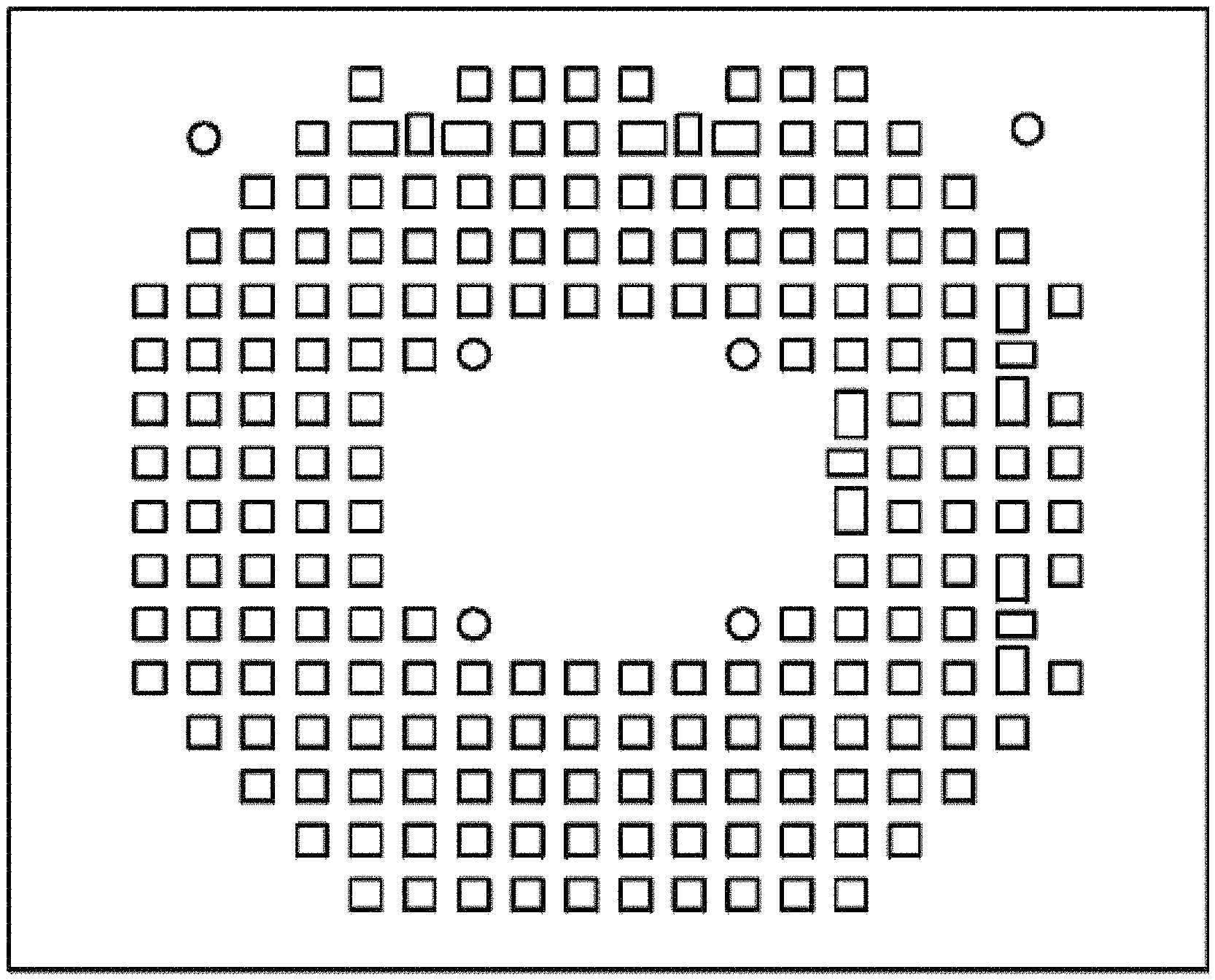
FIG. 1 is a front elevational view of a radio module, showing a first embodiment of my new design;
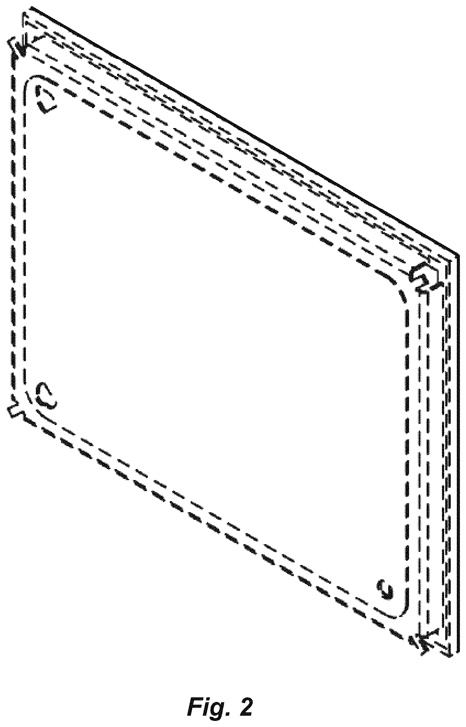
FIG. 2 is a rear perspective view thereof;
FIG. 3 is a rear elevational view thereof.
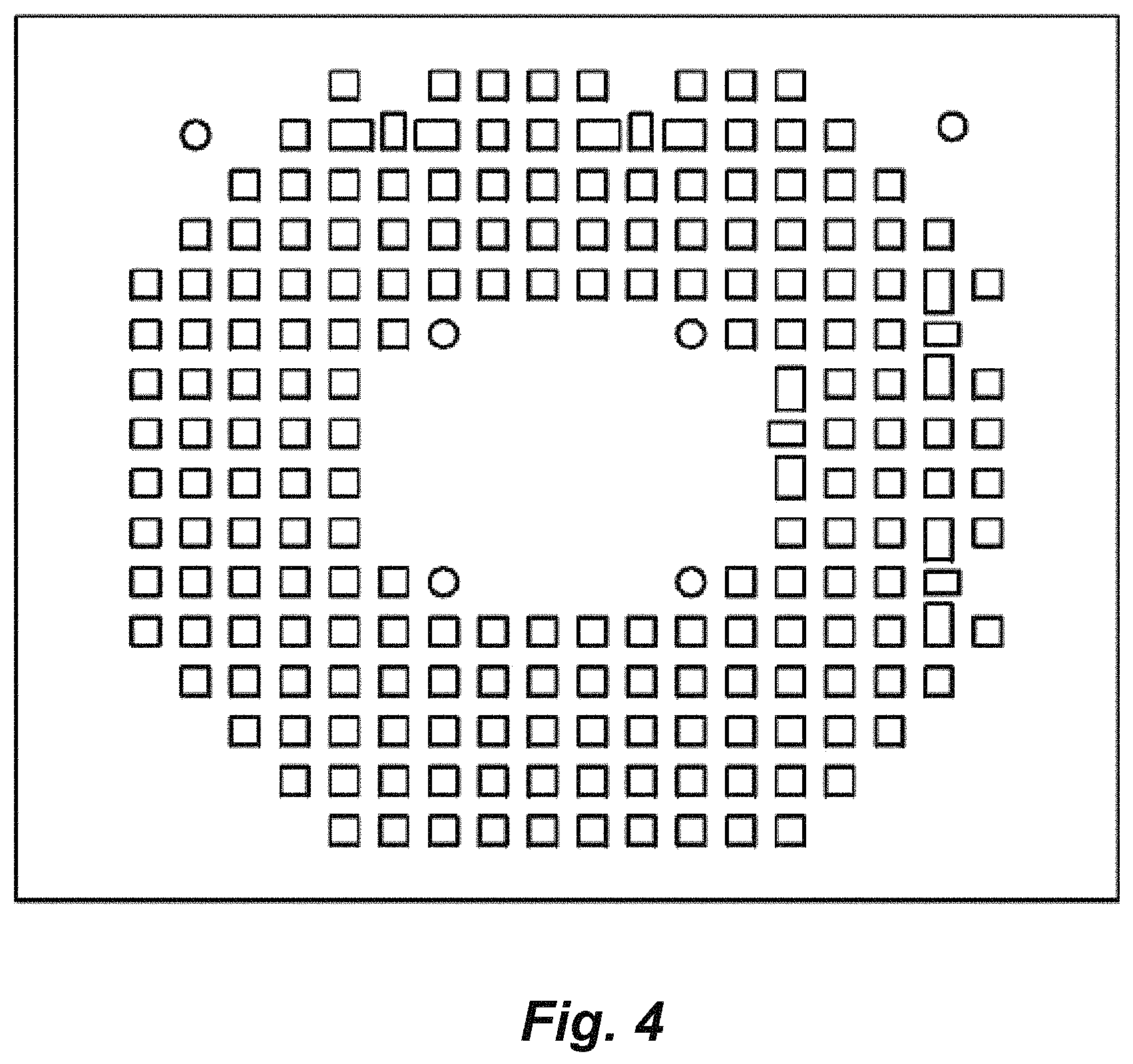
FIG. 4 is a front elevational view of a radio module, showing a second embodiment of my new design;
FIG. 5 is a side elevational view thereof;
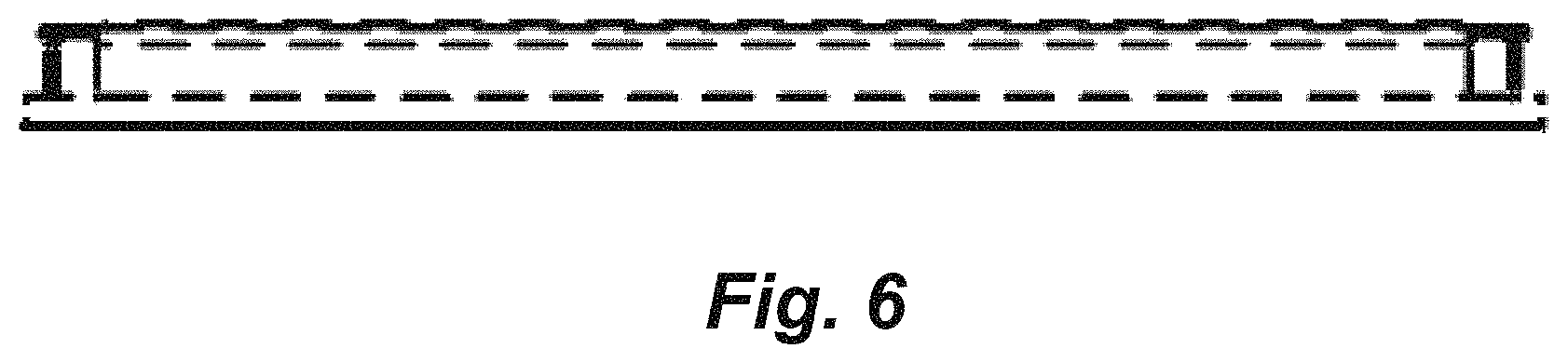
FIG. 6 is a bottom plan view thereof;
FIG. 7 is a rear perspective view thereof;
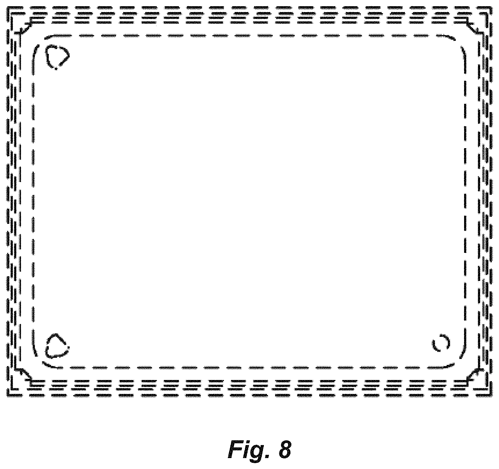
FIG. 8 is a rear elevational view thereof.
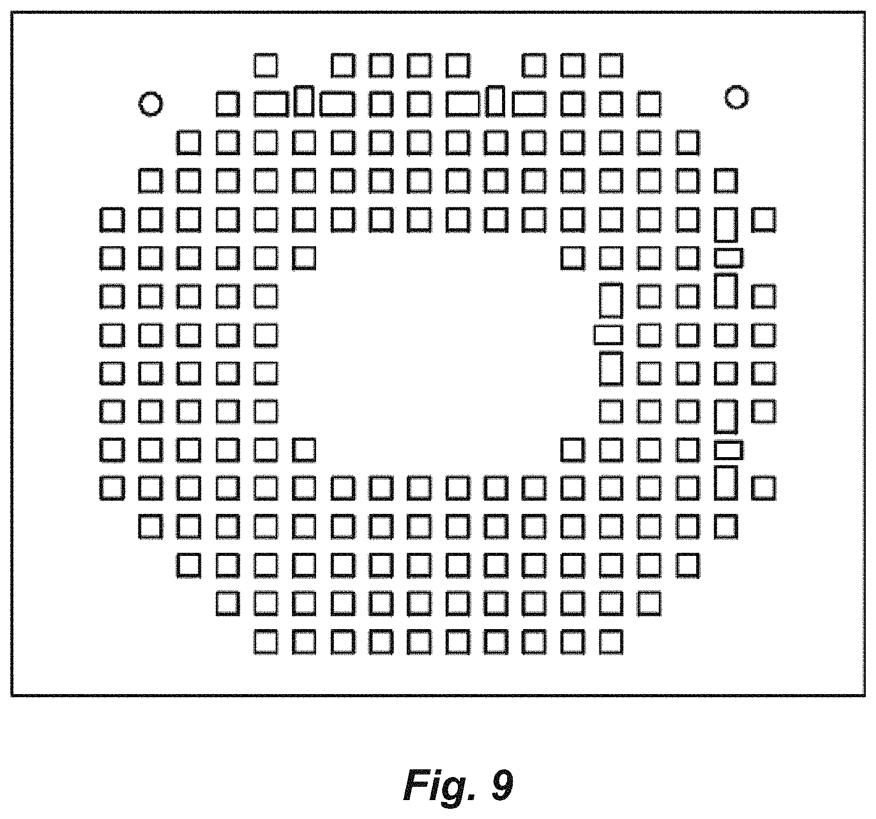
FIG. 9 is a front elevational view of a radio module, showing a third embodiment of my new design;
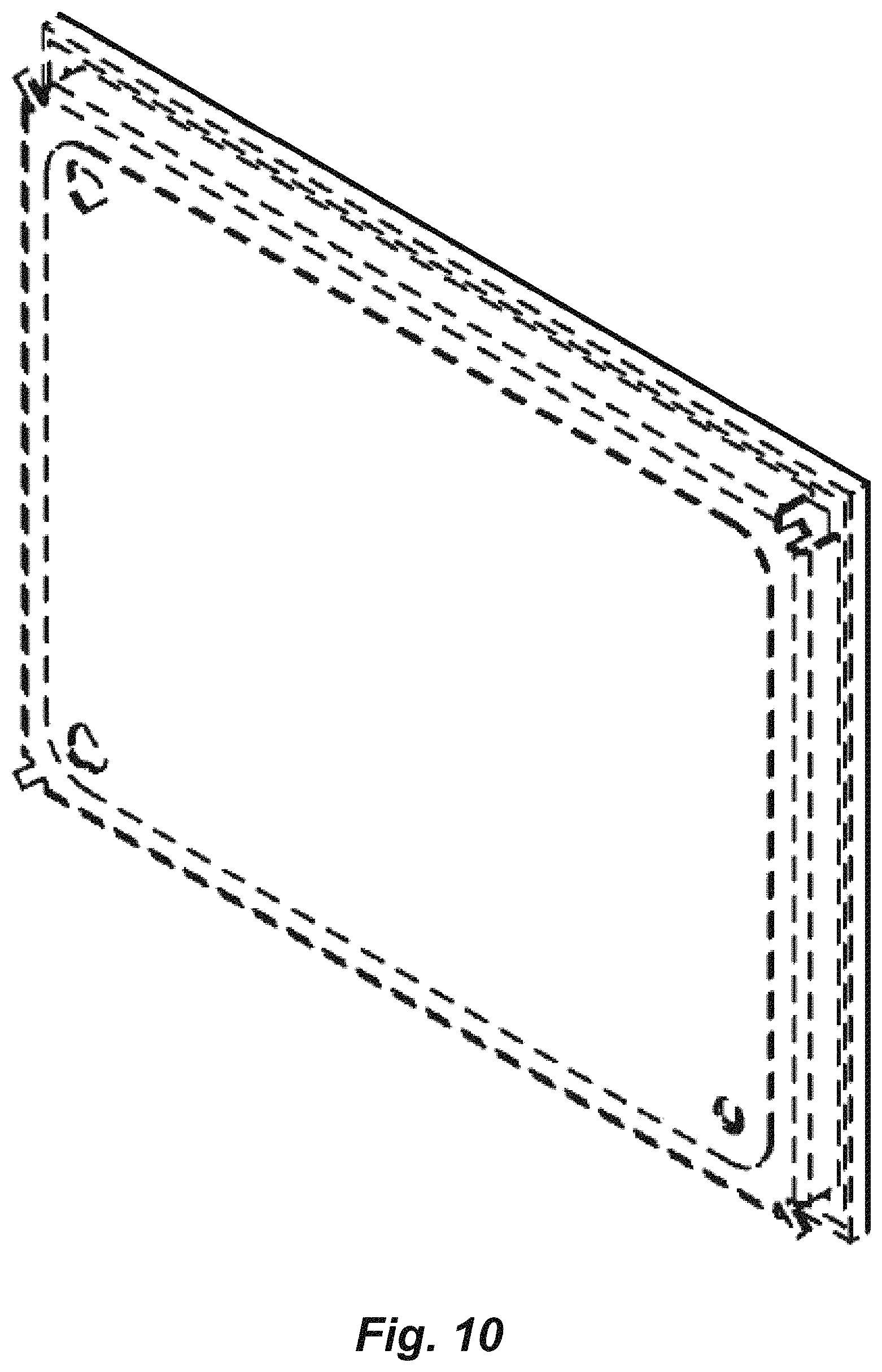
FIG. 10 is a rear perspective view thereof;
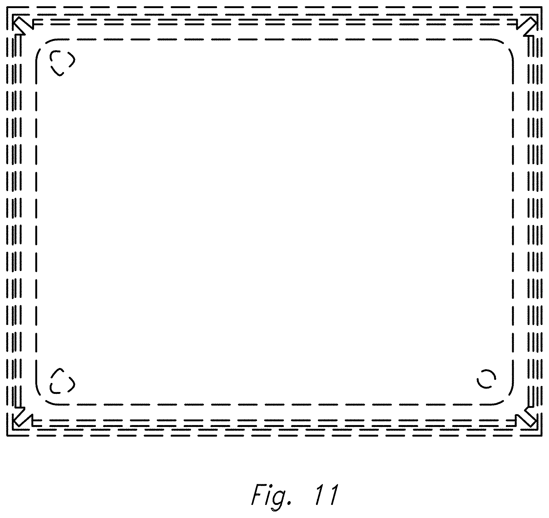
FIG. 11 is a rear elevational view thereof.
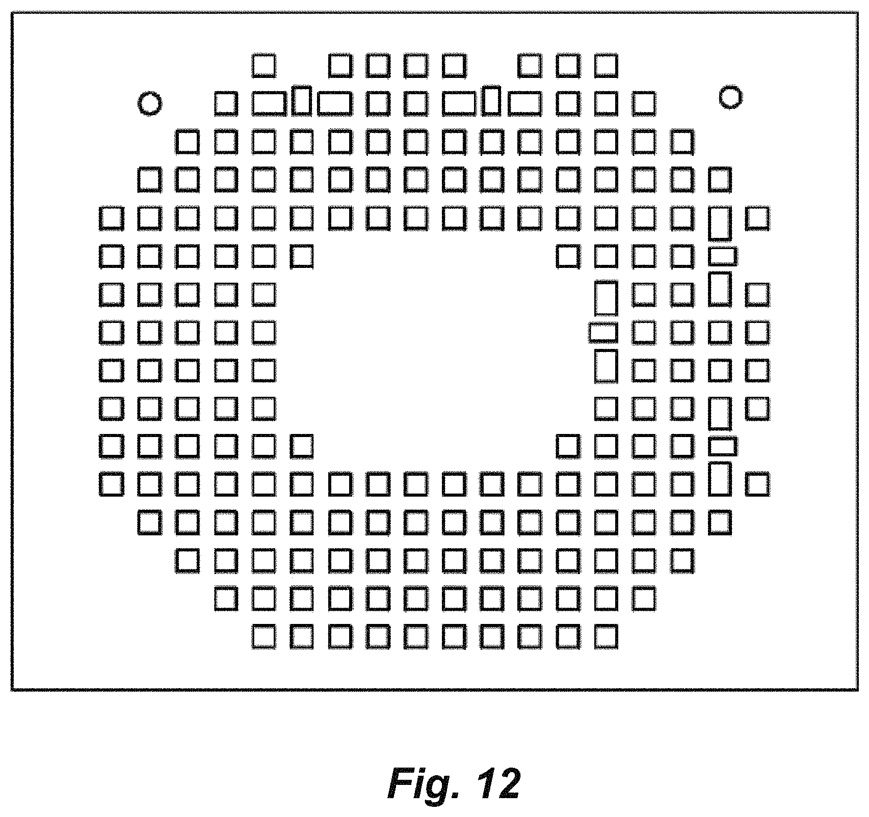
FIG. 12 is a front elevational view of a radio module, showing a fourth embodiment of my new design;
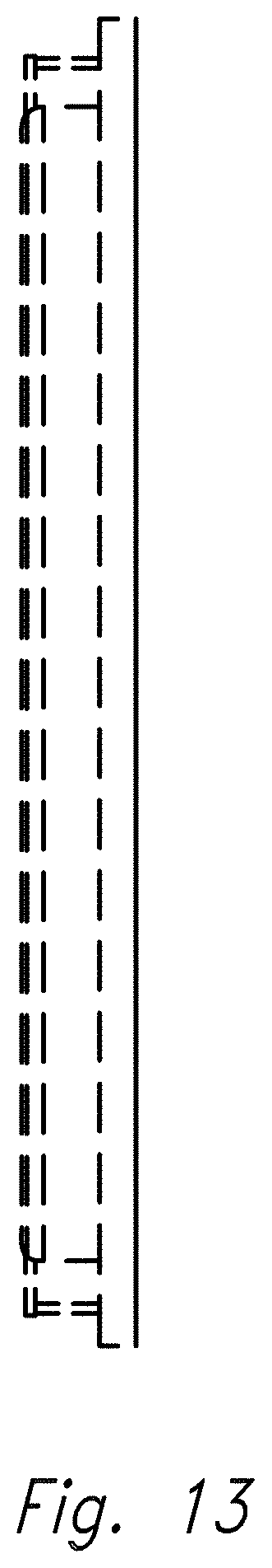
FIG. 13 is a side elevational view thereof;
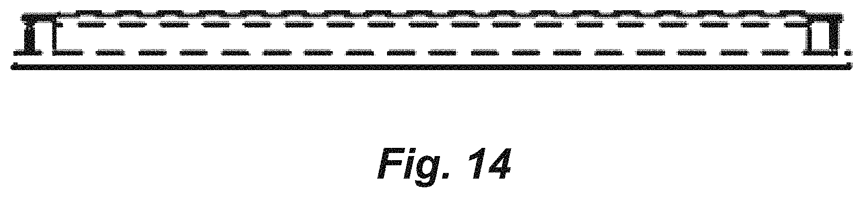
FIG. 14 is a bottom plan view thereof;
FIG. 15 is a rear perspective view thereof;
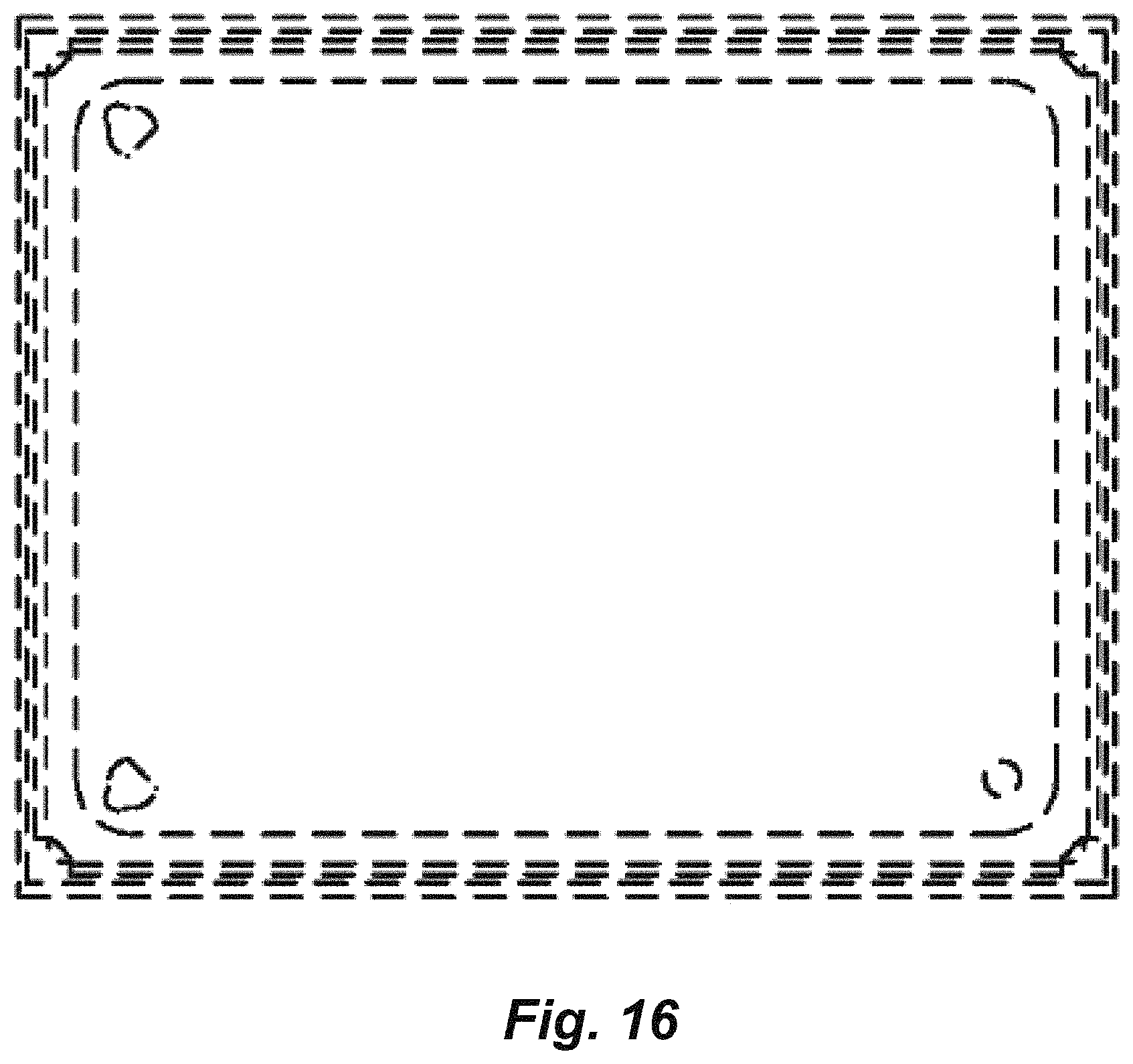
FIG. 16 is a rear elevational view thereof.
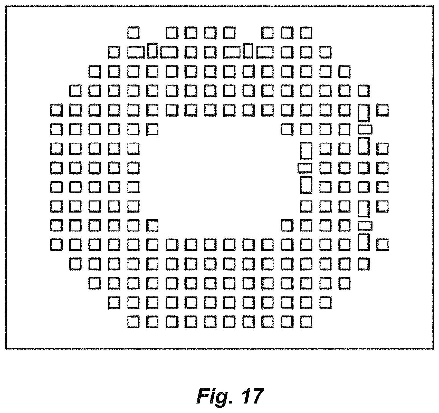
FIG. 17 is a front elevational view of a radio module, showing a fifth embodiment of my new design;
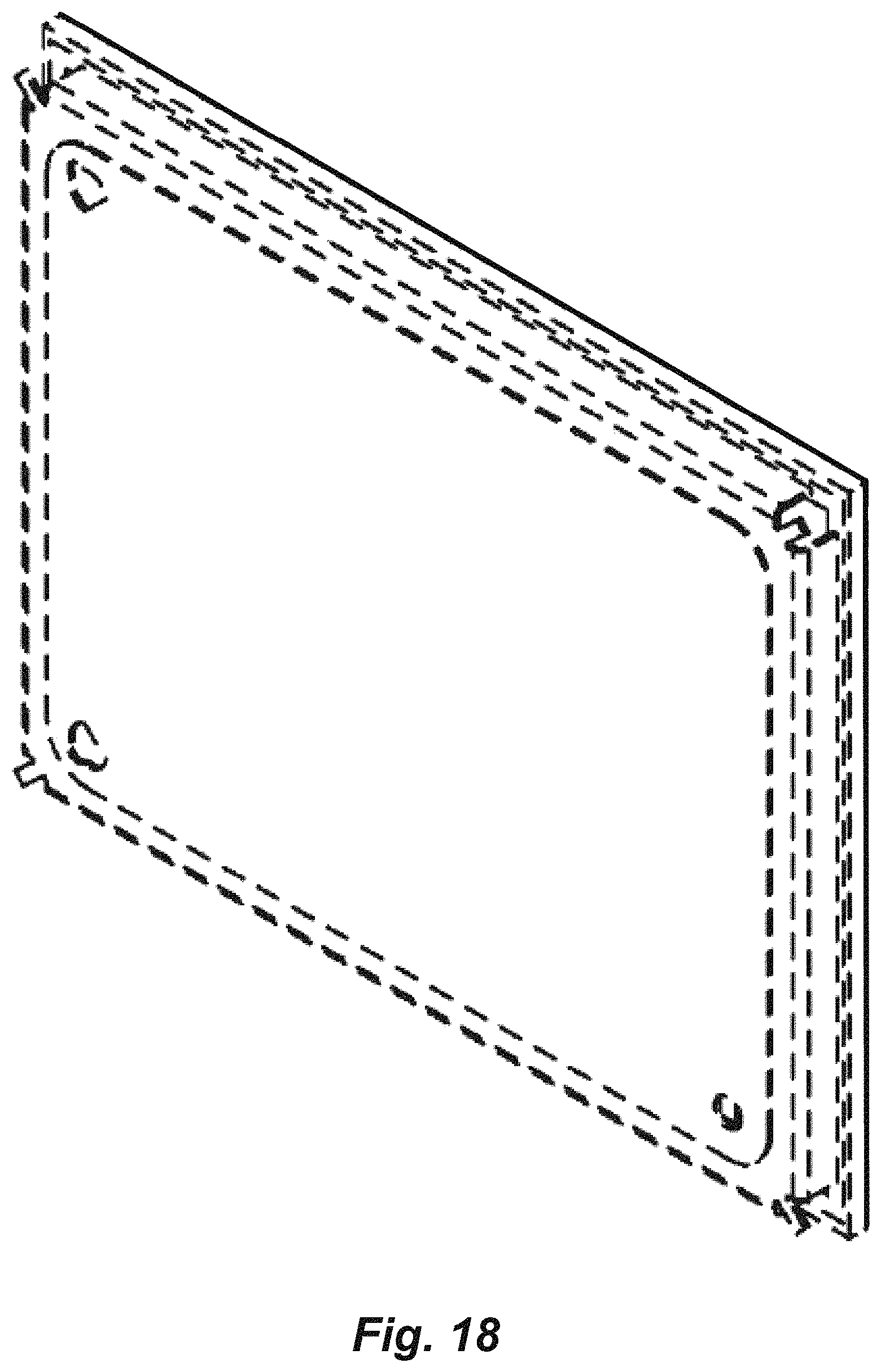
FIG. 18 is a rear perspective view thereof;
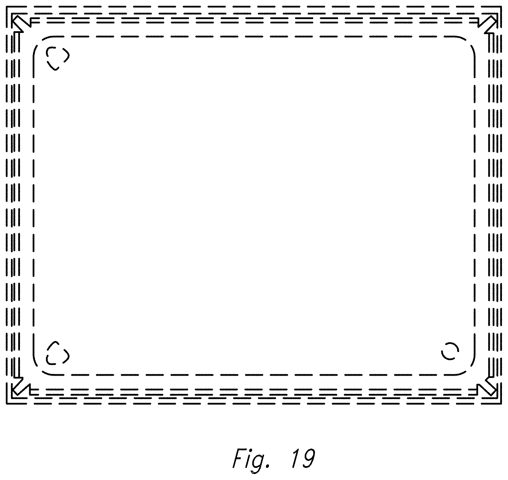
FIG. 19 is a rear elevational view thereof.
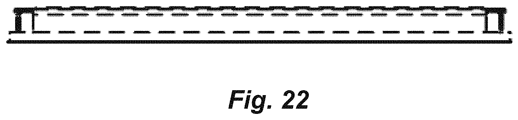
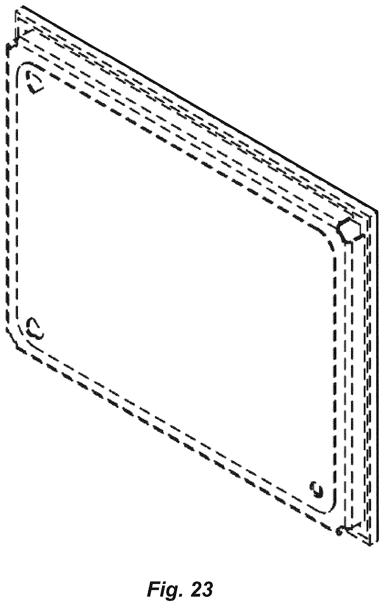
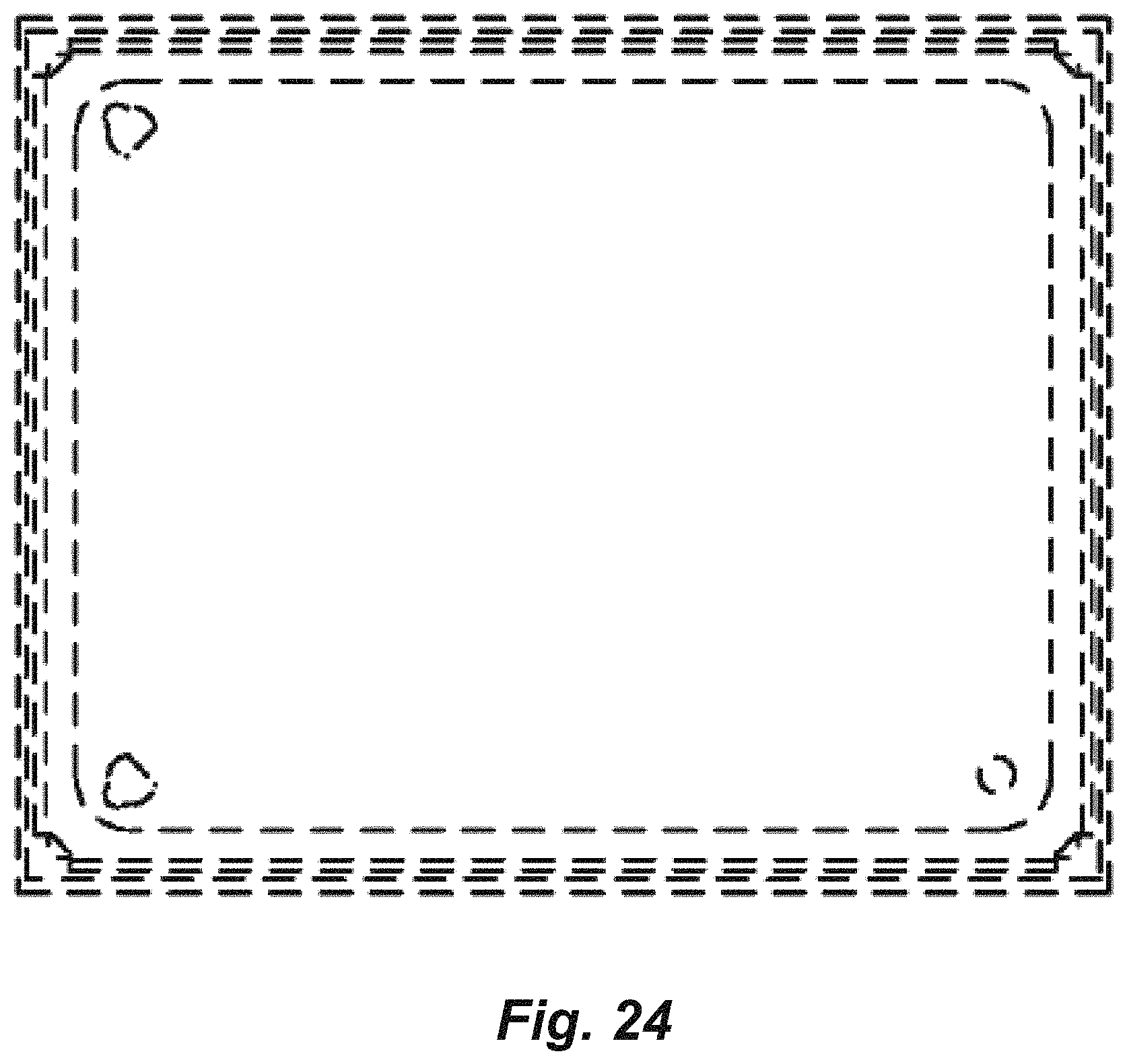
FIG. 20 is a front elevational view of a radio module, showing a sixth embodiment of my new design;
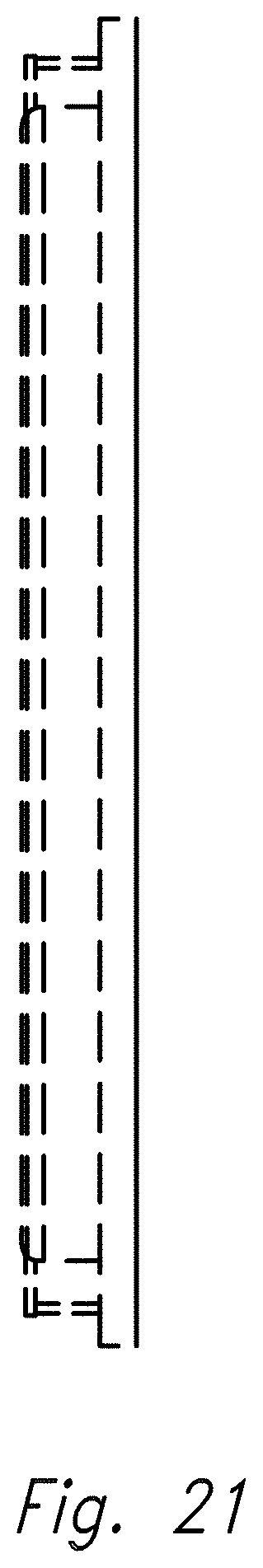
FIG. 21 is a side elevational view thereof;
FIG. 22 is a bottom plan view thereof;
FIG. 23 is a rear perspective view thereof; and,
FIG. 24 is a rear elevational view thereof.
The broken lines in the drawings depict parts of the radio module that form no part of the claimed design.
* * * * *
References
D00000
D00001
D00002
D00003
D00004
D00005
D00006
D00007
D00008
D00009
D00010
D00011
D00012
D00013
D00014
D00015

D00016
D00017
D00018
D00019
D00020

D00021
D00022
D00023
D00024
XML
uspto.report is an independent third-party trademark research tool that is not affiliated, endorsed, or sponsored by the United States Patent and Trademark Office (USPTO) or any other governmental organization. The information provided by uspto.report is based on publicly available data at the time of writing and is intended for informational purposes only.
While we strive to provide accurate and up-to-date information, we do not guarantee the accuracy, completeness, reliability, or suitability of the information displayed on this site. The use of this site is at your own risk. Any reliance you place on such information is therefore strictly at your own risk.
All official trademark data, including owner information, should be verified by visiting the official USPTO website at www.uspto.gov. This site is not intended to replace professional legal advice and should not be used as a substitute for consulting with a legal professional who is knowledgeable about trademark law.