Insertable adaptors and adjustable cushioning shoe heel
Egozi , et al.
U.S. patent number D882,220 [Application Number D/636,456] was granted by the patent office on 2020-04-28 for insertable adaptors and adjustable cushioning shoe heel. This patent grant is currently assigned to THERAFIT FOOTWEAR, LLC. The grantee listed for this patent is THERAFIT FOOTWEAR, LLC. Invention is credited to William T. Anderson, Moises Egozi.


View All Diagrams
| United States Patent | D882,220 |
| Egozi , et al. | April 28, 2020 |
Insertable adaptors and adjustable cushioning shoe heel
Claims
CLAIM The ornamental design for insertable adaptors and adjustable cushioning shoe heel, as shown and described.
| Inventors: | Egozi; Moises (Miami Gardens, FL), Anderson; William T. (Miami Gardens, FL) | ||||||||||
|---|---|---|---|---|---|---|---|---|---|---|---|
| Applicant: |
|
||||||||||
| Assignee: | THERAFIT FOOTWEAR, LLC (Miami
Gardens, FL) |
||||||||||
| Appl. No.: | D/636,456 | ||||||||||
| Filed: | February 8, 2018 |
Related U.S. Patent Documents
| Application Number | Filing Date | Patent Number | Issue Date | ||
|---|---|---|---|---|---|
| 29624767 | Nov 3, 2017 | ||||
| 29525713 | Nov 7, 2017 | D801649 | |||
| 13899547 | May 21, 2013 | ||||
| Current U.S. Class: | D2/947; D2/952 |
| Current International Class: | 0204 |
| Field of Search: | ;D2/902,906,908,916,918,925,946-962,977 ;36/3B,22R,24.5,25R,28,32R,34R,59C,67A,103 |
References Cited [Referenced By]
U.S. Patent Documents
| 1670747 | May 1928 | Sestito |
| 3785646 | January 1974 | Ruskin |
| D248192 | June 1978 | Stevenson |
| 4236326 | December 1980 | Inohara |
| 4430810 | February 1984 | Bente |
| 4442614 | April 1984 | Farberov |
| 4445284 | May 1984 | Sakutori |
| 4527345 | July 1985 | Lopez Lopez |
| 4573279 | March 1986 | Feurer-Zogel |
| 4782603 | November 1988 | Brown |
| 4864738 | September 1989 | Horovitz |
| 4887367 | December 1989 | Mackness |
| 4888887 | December 1989 | Solow |
| 4914836 | April 1990 | Horovitz |
| 5005300 | April 1991 | Diaz |
| 5224277 | July 1993 | Sang Do |
| D340350 | October 1993 | Kilgore |
| 5406719 | April 1995 | Potter |
| 5718064 | February 1998 | Pyle |
| D401746 | December 1998 | Brooks |
| 5853844 | December 1998 | Wen |
| 5907911 | June 1999 | Huang |
| 5921003 | July 1999 | Kim |
| 6321465 | November 2001 | Bonk |
| 6397498 | June 2002 | Yoo |
| D474331 | May 2003 | Dean |
| D495856 | September 2004 | McClaskie |
| 6807753 | October 2004 | Steszyn |
| 6983553 | January 2006 | Lussier |
| 7363732 | April 2008 | Hernandez |
| D604487 | November 2009 | McClaskie |
| D608535 | January 2010 | McClaskie |
| D625495 | October 2010 | McClaskie |
| D625908 | October 2010 | McClaskie |
| 8056268 | November 2011 | DiBenedetto |
| D662295 | June 2012 | Raysse |
| D670484 | November 2012 | McClaskie |
| D670485 | November 2012 | McClaskie |
| D674175 | January 2013 | McClaskie |
| D680312 | April 2013 | Raysse |
| D685984 | July 2013 | Raysse |
| D698135 | January 2014 | McClaskie |
| D698137 | January 2014 | Carr |
| D699025 | February 2014 | McClaskie |
| D707937 | July 2014 | Kitagawa |
| D712123 | September 2014 | Goldman |
| D716025 | October 2014 | Seo |
| D719329 | December 2014 | Smith |
| 8935861 | January 2015 | Baker |
| D730638 | June 2015 | Christensen |
| D738082 | September 2015 | Ho |
| D740009 | October 2015 | Pinto |
| D744731 | December 2015 | Wawrousek |
| D754956 | May 2016 | McCourt |
| D765957 | September 2016 | Dupuy |
| D795544 | August 2017 | de Montgolfier |
| D796167 | September 2017 | Bates |
| D797423 | September 2017 | Bischoff |
| D801649 | November 2017 | Egozi |
| D805273 | December 2017 | Birkinhead |
| D806372 | January 2018 | Boudreau |
| D807003 | January 2018 | Humphrey |
| D812863 | March 2018 | Birkinhead |
| 9931804 | April 2018 | Le |
| 9936766 | April 2018 | Brandt |
| 9955750 | May 2018 | Montross |
| D819317 | June 2018 | Wurtz |
| 9986786 | June 2018 | Wang |
| 10016017 | July 2018 | Christensen |
| 10034517 | July 2018 | Christensen |
| D836893 | January 2019 | Bischoff |
| D838942 | January 2019 | Sassi |
| D841300 | February 2019 | Albrecht |
| D852474 | July 2019 | Sassi |
| D858079 | September 2019 | Avar |
| D858959 | September 2019 | Sassi |
| D861305 | October 2019 | Cameron |
| 2003/0208928 | November 2003 | Steszyn |
| 2004/0035025 | February 2004 | Choi |
| 2004/0148799 | August 2004 | Lussier |
| 2004/0177531 | September 2004 | DiBenedetto |
| 2006/0010720 | January 2006 | Kim |
| 2006/0168710 | August 2006 | Vito |
| 2006/0236562 | October 2006 | Wang |
| 2007/0113425 | May 2007 | Wakley |
| 2008/0216352 | September 2008 | Baucom |
| 2009/0151196 | June 2009 | Schindler |
| 2009/0293309 | December 2009 | Keating |
| 2009/0293311 | December 2009 | Sun |
| 2010/0293811 | November 2010 | Truelsen |
| 2010/0307025 | December 2010 | Truelsen |
| 2014/0196308 | July 2014 | Baratta |
| 2014/0237851 | August 2014 | Goldston |
| 2014/0325871 | November 2014 | Price |
| 2016/0040743 | February 2016 | Staton |
| 2016/0310309 | October 2016 | Schoenhaus |
| 2017/0251753 | September 2017 | Meschter |
| 2017/0251754 | September 2017 | Meschter |
| 2017/0251756 | September 2017 | Meschter |
| 2017/0265564 | September 2017 | Peyton |
| 2018/0070675 | March 2018 | Campos, II |
| 2018/0242683 | August 2018 | Van Atta |
| 2018/0289105 | October 2018 | Hatfield |
| 2018/0339478 | November 2018 | Lee |
Attorney, Agent or Firm: Daniel S. Polley, P.A.
Description
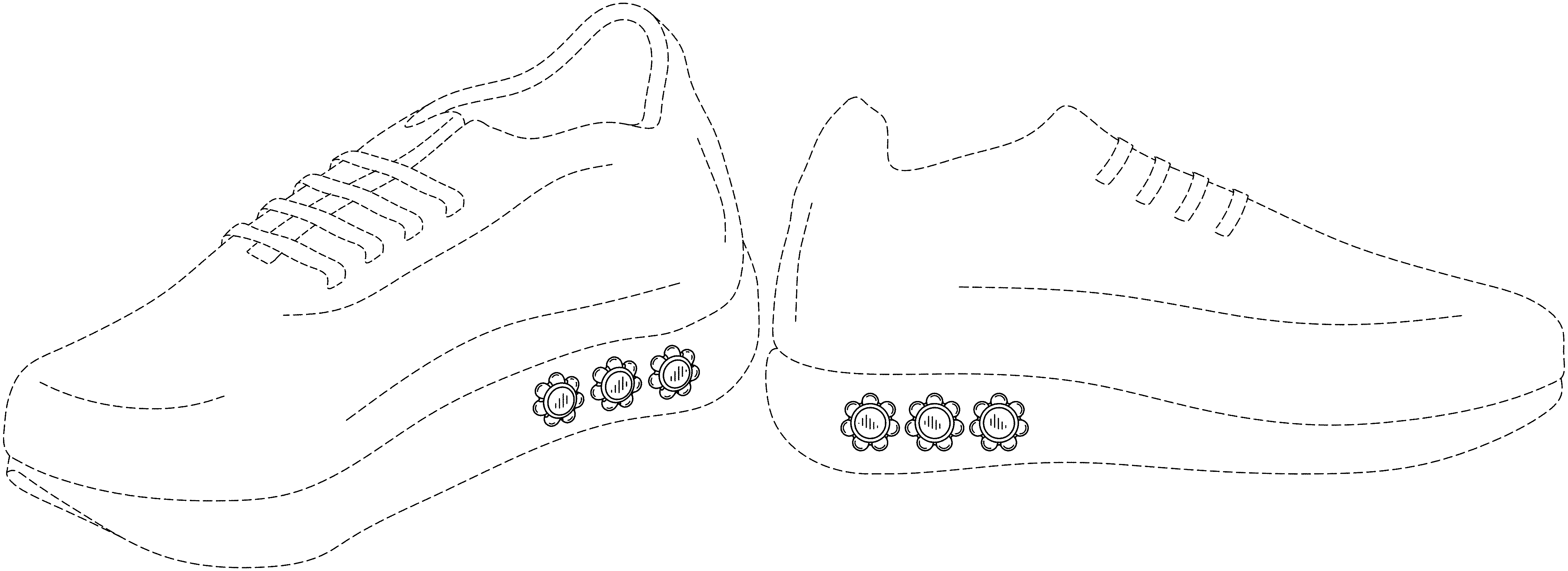
FIG. 1 is a front top perspective view of the insertable adaptors and adjustable cushioning shoe heel, showing the new design;
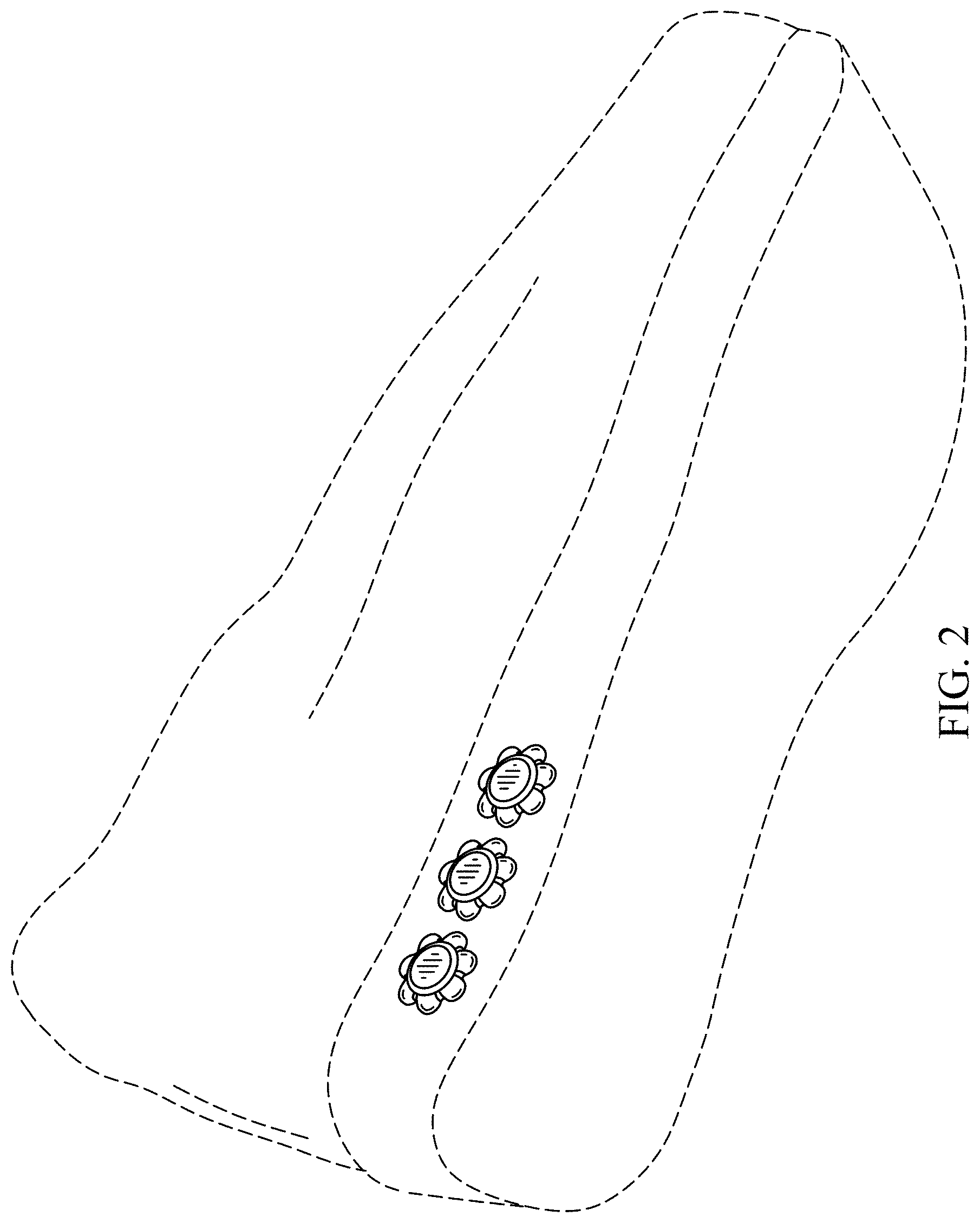
FIG. 2 is a bottom back perspective view thereof;
FIG. 3 is a top view thereof;
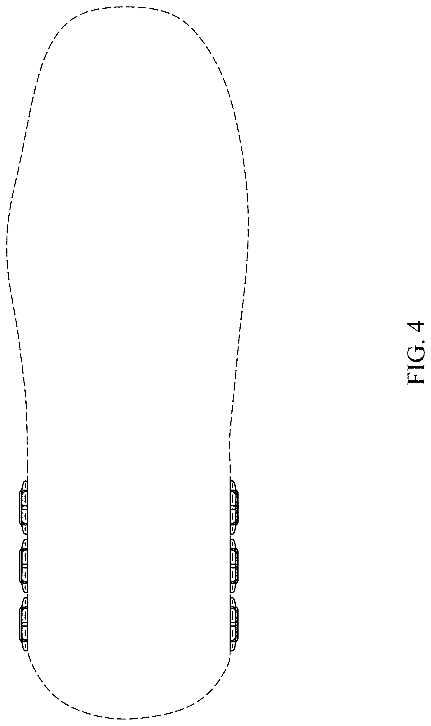
FIG. 4 is a bottom view thereof;
FIG. 5 is a right side elevational view thereof;
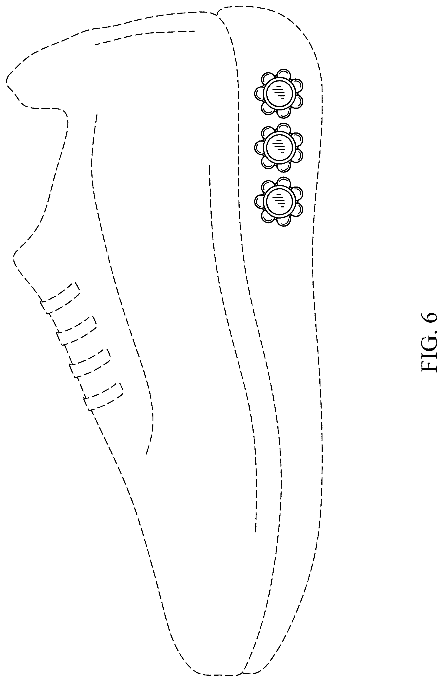
FIG. 6 is a left side elevational view thereof.
FIG. 7 is a front view thereof;
FIG. 8 is a back view thereof;
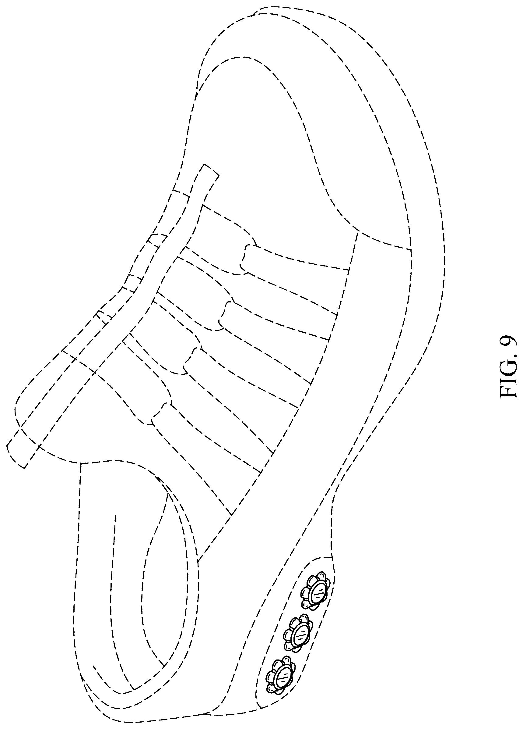
FIG. 9 is a back top perspective view of the insertable adaptors and adjustable cushioning shoe heel shown in connection with a different type of broken line shoe environment as the design can be incorporated into various types of shoe environments and is not considered limited to any particular shoe environment;
FIG. 10 is a back top perspective view of the insertable adaptors and adjustable cushioning shoe heel shown in connection with another type of broken line shoe environment;
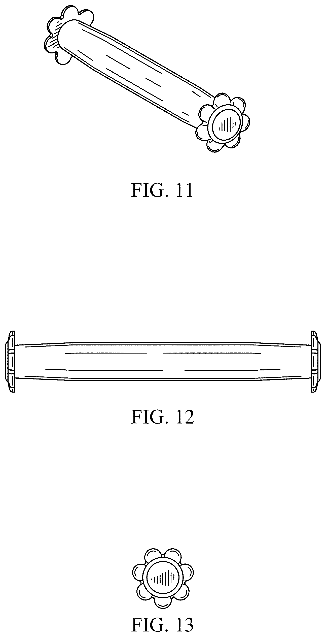
FIG. 11 is a perspective view of a single insertable adaptor of the insertable adaptors and adjustable cushioning shoe heel shown removed from the shoe heel so that it might be depicted in full;
FIG. 12 is a side elevational view thereof;
FIG. 13 is an end view thereof with the opposite end being a mirror image;
FIG. 14 is a front perspective view with two insertable adaptors within the shoe heel and one removed;
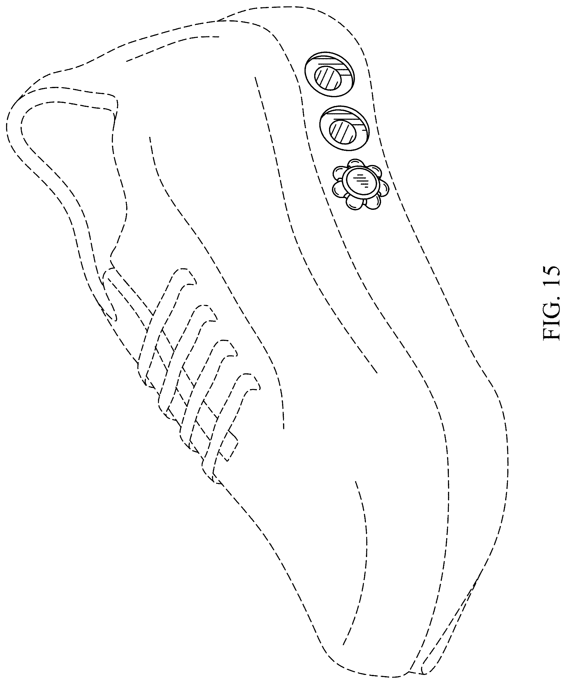
FIG. 15 is a front perspective view with one insertable adaptor with the shoe heel and two removed;
FIG. 16 is a partial side elevational view of the insertable adaptors and adjustable cushioning shoe heel showing two insertable adaptors with a shoe heel opening to the right of the two adaptors;
FIG. 17 is a partial side elevational view of the insertable adaptors and adjustable cushioning shoe heel showing two insertable adaptors with a shoe heel opening to the left of the two adaptors;
FIG. 18 is a partial side elevational view of the insertable adaptors and adjustable cushioning shoe heel showing two insertable adaptors with a shoe heel opening in the middle of the two adaptors;
FIG. 19 is a partial side elevational view of the insertable adaptors and adjustable cushioning shoe heel showing one insertable adaptor with two shoe heel openings to the left of the one adaptor;
FIG. 20 is a partial side elevational view of the insertable adaptors and adjustable cushioning shoe heel showing one insertable adaptor with one shoe heel opening to the left of the one adaptor and one shoe heel opening to the right of the one adaptor;
FIG. 21 is a partial side elevational view of the insertable adaptors and adjustable cushioning shoe heel showing one insertable adaptor with two shoe heel openings to the right of the one adaptor; and,
FIG. 22 is a partial side elevational view of the insertable adaptors and adjustable cushioning shoe heel showing three insertable adaptors disposed within the shoe heel.
The broken lines in FIGS. 1 through 10 and FIGS. 14 and 15 show environmental structure and unclaimed subject matter in the form of a shoe that forms no part of the claimed design. The broken lines in FIGS. 16 through 22 define the boundaries of the partial views and also form no part of the claimed design.
* * * * *
D00000
D00001
D00002
D00003
D00004
D00005
D00006
D00007
D00008
D00009
D00010
D00011
D00012
D00013

XML
uspto.report is an independent third-party trademark research tool that is not affiliated, endorsed, or sponsored by the United States Patent and Trademark Office (USPTO) or any other governmental organization. The information provided by uspto.report is based on publicly available data at the time of writing and is intended for informational purposes only.
While we strive to provide accurate and up-to-date information, we do not guarantee the accuracy, completeness, reliability, or suitability of the information displayed on this site. The use of this site is at your own risk. Any reliance you place on such information is therefore strictly at your own risk.
All official trademark data, including owner information, should be verified by visiting the official USPTO website at www.uspto.gov. This site is not intended to replace professional legal advice and should not be used as a substitute for consulting with a legal professional who is knowledgeable about trademark law.