Implant inserters and related methods
Saito April 6, 2
U.S. patent number 10,966,843 [Application Number 16/037,168] was granted by the patent office on 2021-04-06 for implant inserters and related methods. This patent grant is currently assigned to DePuy Synthes Products, Inc.. The grantee listed for this patent is DePuy Synthes Products, Inc.. Invention is credited to Koki Saito.


View All Diagrams
| United States Patent | 10,966,843 |
| Saito | April 6, 2021 |
Implant inserters and related methods
Abstract
Implant inserters and related methods are disclosed herein, e.g., for delivering a fusion cage or other implant to a spinal disc space and for rotating or articulating the implant within the disc space. An exemplary instrument can include a slider that is slidably mounted to a body to define an implant clamp. A locking mechanism can allow the slider to be quickly disassembled from the body and for fast and convenient loading and unloading of an implant to the instrument. An actuation knob can be moved between a first position in which the implant is locked from rotating relative to the instrument and a second position in which the implant is retained to the instrument but allowed to rotate relative to the instrument.
| Inventors: | Saito; Koki (Tokyo, JP) | ||||||||||
|---|---|---|---|---|---|---|---|---|---|---|---|
| Applicant: |
|
||||||||||
| Assignee: | DePuy Synthes Products, Inc.
(Raynham, MA) |
||||||||||
| Family ID: | 1000005467109 | ||||||||||
| Appl. No.: | 16/037,168 | ||||||||||
| Filed: | July 17, 2018 |
Prior Publication Data
| Document Identifier | Publication Date | |
|---|---|---|
| US 20190038434 A1 | Feb 7, 2019 | |
Related U.S. Patent Documents
| Application Number | Filing Date | Patent Number | Issue Date | ||
|---|---|---|---|---|---|
| 62534039 | Jul 18, 2017 | ||||
| Current U.S. Class: | 1/1 |
| Current CPC Class: | A61F 2/4611 (20130101); A61F 2/4603 (20130101); A61F 2002/30507 (20130101); A61F 2002/30538 (20130101); A61F 2002/4622 (20130101); A61F 2002/4627 (20130101); A61F 2002/4628 (20130101) |
| Current International Class: | A61F 2/46 (20060101); A61F 2/30 (20060101) |
References Cited [Referenced By]
U.S. Patent Documents
| 3426364 | February 1969 | Lumb |
| 3867728 | February 1975 | Stubstad et al. |
| 4105034 | August 1978 | Shalaby et al. |
| 4130639 | December 1978 | Shalaby et al. |
| 4140678 | February 1979 | Shalaby et al. |
| 4141087 | February 1979 | Shalaby et al. |
| 4205399 | June 1980 | Shalaby et al. |
| 4208511 | June 1980 | Shalaby et al. |
| 4298993 | November 1981 | Kovaleva et al. |
| 4349921 | September 1982 | Kuntz |
| 4394370 | July 1983 | Jefferies |
| 4450591 | May 1984 | Rappaport |
| 4454374 | June 1984 | Pollack |
| 4538612 | September 1985 | Patrick, Jr. |
| 4545374 | October 1985 | Jacobson |
| 4599086 | July 1986 | Doty |
| 4627853 | December 1986 | Campbell et al. |
| 4714469 | December 1987 | Kenna |
| 4743256 | May 1988 | Brantigan |
| 4781721 | November 1988 | Grundei |
| 4829152 | May 1989 | Rostoker et al. |
| 4834757 | May 1989 | Brantigan |
| 4863476 | September 1989 | Shepperd |
| 4872452 | October 1989 | Alexson |
| 4877020 | October 1989 | Vich et al. |
| 4878915 | November 1989 | Brantigan |
| 4904261 | February 1990 | Dove et al. |
| 4911718 | March 1990 | Lee et al. |
| 4917704 | April 1990 | Frey et al. |
| 4927425 | May 1990 | Lozier |
| 4941481 | July 1990 | Wagenknecht |
| 4955908 | September 1990 | Frey et al. |
| 4995200 | February 1991 | Eberhart |
| 4997432 | March 1991 | Keller |
| 5006120 | April 1991 | Carter |
| 5006121 | April 1991 | Hafeli |
| 5015247 | May 1991 | Michelson |
| 5019082 | May 1991 | Frey et al. |
| 5047058 | September 1991 | Roberts et al. |
| 5116374 | May 1992 | Stone |
| 5123926 | June 1992 | Pisharodi |
| 5133719 | July 1992 | Winston |
| 5163939 | November 1992 | Winston |
| 5169402 | December 1992 | Elloy |
| 5171240 | December 1992 | Hanwong |
| 5171278 | December 1992 | Pisharodi |
| 5171281 | December 1992 | Parsons et al. |
| 5190549 | March 1993 | Miller et al. |
| 5192327 | March 1993 | Brantigan |
| 5201736 | April 1993 | Strauss |
| 5217475 | June 1993 | Kuber |
| 5250061 | October 1993 | Michelson |
| 5258031 | November 1993 | Salib et al. |
| 5282861 | February 1994 | Kaplan |
| 5298254 | March 1994 | Prewett et al. |
| 5306307 | April 1994 | Senter et al. |
| 5306308 | April 1994 | Gross et al. |
| 5306309 | April 1994 | Wagner et al. |
| 5320644 | June 1994 | Baumgartner |
| 5342365 | August 1994 | Waldman |
| 5387215 | February 1995 | Fisher |
| 5390683 | February 1995 | Pisharodi |
| 5397364 | March 1995 | Kozak et al. |
| 5425772 | June 1995 | Brantigan |
| 5431658 | July 1995 | Moskovich |
| 5443514 | August 1995 | Steffee |
| 5443515 | August 1995 | Cohen et al. |
| 5454815 | October 1995 | Geisser et al. |
| 5454827 | October 1995 | Aust et al. |
| 5464929 | November 1995 | Bezwada et al. |
| 5476466 | December 1995 | Barrette et al. |
| 5484437 | January 1996 | Michelson |
| 5522899 | June 1996 | Michelson |
| 5540693 | July 1996 | Fisher |
| 5545229 | August 1996 | Parsons et al. |
| 5550172 | August 1996 | Regula et al. |
| 5554191 | September 1996 | Lahille |
| 5556431 | September 1996 | Buttner-Janz |
| 5595751 | January 1997 | Bezwada et al. |
| 5597579 | January 1997 | Bezwada et al. |
| 5601561 | February 1997 | Terry et al. |
| 5607687 | March 1997 | Bezwada et al. |
| 5609635 | March 1997 | Michelson |
| 5618552 | April 1997 | Bezwada et al. |
| 5620448 | April 1997 | Puddu |
| 5620698 | April 1997 | Bezwada et al. |
| 5645596 | July 1997 | Kim et al. |
| 5645850 | July 1997 | Bezwada et al. |
| 5648088 | July 1997 | Bezwada et al. |
| 5658335 | August 1997 | Allen |
| 5658336 | August 1997 | Pisharodi |
| 5665122 | September 1997 | Kambin |
| 5669909 | September 1997 | Zdeblick et al. |
| 5674296 | October 1997 | Bryan et al. |
| 5683463 | November 1997 | Godefroy et al. |
| 5693100 | December 1997 | Pisharodi |
| 5698213 | December 1997 | Jamiolkowski et al. |
| 5700583 | December 1997 | Jamiolkowski et al. |
| 5702449 | December 1997 | McKay |
| 5702463 | December 1997 | Pothier et al. |
| 5707371 | January 1998 | Metz-Stavenhagen et al. |
| 5725531 | March 1998 | Shapiro |
| 5728159 | March 1998 | Stroever et al. |
| 5755798 | May 1998 | Papavero et al. |
| 5766251 | June 1998 | Koshino |
| 5766252 | June 1998 | Henry et al. |
| 5772661 | June 1998 | Michelson |
| 5782830 | July 1998 | Farris |
| 5782919 | July 1998 | Zdeblick et al. |
| 5836948 | November 1998 | Zucherman et al. |
| 5857995 | January 1999 | Thomas et al. |
| 5859150 | January 1999 | Jamiolkowski et al. |
| 5860973 | January 1999 | Michelson |
| 5865845 | February 1999 | Thalgott |
| 5865848 | February 1999 | Baker |
| 5888222 | March 1999 | Coates et al. |
| 5888223 | March 1999 | Bray, Jr. |
| 5893890 | April 1999 | Pisharodi |
| 5906616 | May 1999 | Pavlov et al. |
| 5916228 | June 1999 | Ripich et al. |
| 5925056 | July 1999 | Thomas |
| 5964807 | October 1999 | Gan et al. |
| 5968098 | October 1999 | Winslow |
| 5976187 | November 1999 | Richelsoph |
| 5980522 | November 1999 | Koros et al. |
| 5989289 | November 1999 | Coates et al. |
| 6001099 | December 1999 | Huebner |
| 6008433 | December 1999 | Stone |
| 6039761 | March 2000 | Li et al. |
| 6039762 | March 2000 | McKay |
| 6045579 | April 2000 | Hochshuler et al. |
| 6053922 | April 2000 | Krause et al. |
| 6056763 | May 2000 | Parsons |
| 6066174 | May 2000 | Farris |
| 6066175 | May 2000 | Henderson et al. |
| 6080158 | June 2000 | Lin |
| 6086593 | July 2000 | Bonutti |
| 6099531 | August 2000 | Bonutti |
| 6106557 | August 2000 | Robioneck et al. |
| 6120508 | September 2000 | Grunig et al. |
| 6126689 | October 2000 | Brett |
| 6139558 | October 2000 | Wagner |
| 6143032 | November 2000 | Schafer et al. |
| 6146421 | November 2000 | Gordon et al. |
| 6159215 | December 2000 | Urbahns et al. |
| 6174311 | January 2001 | Branch et al. |
| 6176882 | January 2001 | Biedermann et al. |
| 6206922 | March 2001 | Zdeblick et al. |
| 6231610 | May 2001 | Geisler |
| 6235059 | May 2001 | Benezech et al. |
| 6241733 | June 2001 | Nicholson et al. |
| 6245108 | June 2001 | Biscup |
| 6251140 | June 2001 | Marino et al. |
| 6258093 | July 2001 | Edwards et al. |
| 6296644 | October 2001 | Saurat et al. |
| 6309421 | October 2001 | Pisharodi |
| D450676 | November 2001 | Huttner |
| 6319257 | November 2001 | Carignan et al. |
| 6332894 | December 2001 | Stalcup et al. |
| 6342074 | January 2002 | Simpson |
| 6364880 | April 2002 | Michelson |
| 6371988 | April 2002 | Pafford et al. |
| 6387130 | May 2002 | Stone et al. |
| 6398793 | June 2002 | McGuire |
| 6409766 | June 2002 | Brett |
| 6413278 | July 2002 | Marchosky |
| 6423095 | July 2002 | Van Hoeck et al. |
| 6425920 | July 2002 | Hamada |
| 6428544 | August 2002 | Ralph et al. |
| 6432106 | August 2002 | Fraser |
| 6436101 | August 2002 | Hamada |
| 6443987 | September 2002 | Bryan |
| 6447518 | September 2002 | Krause et al. |
| 6447544 | September 2002 | Michelson |
| 6482233 | November 2002 | Aebi et al. |
| 6511509 | January 2003 | Ford et al. |
| 6579318 | June 2003 | Varga et al. |
| 6582432 | June 2003 | Michelson |
| 6595998 | July 2003 | Johnson et al. |
| 6599294 | July 2003 | Fuss et al. |
| 6605089 | August 2003 | Michelson |
| 6610066 | August 2003 | Dinger et al. |
| 6610089 | August 2003 | Liu et al. |
| 6635060 | October 2003 | Hanson et al. |
| RE38335 | November 2003 | Aust et al. |
| 6641582 | November 2003 | Hanson et al. |
| 6648915 | November 2003 | Sazy |
| 6660004 | December 2003 | Barker et al. |
| 6676703 | January 2004 | Biscup |
| 6699288 | March 2004 | Moret et al. |
| 6719794 | April 2004 | Gerber et al. |
| 6733535 | May 2004 | Michelson |
| 6746484 | June 2004 | Liu et al. |
| 6755837 | June 2004 | Ebner |
| 6764491 | July 2004 | Frey |
| 6767366 | July 2004 | Lee et al. |
| 6830570 | December 2004 | Frey et al. |
| 6835206 | December 2004 | Jackson |
| 6835208 | December 2004 | Marchosky |
| 6840941 | January 2005 | Rogers et al. |
| 6852127 | February 2005 | Varga et al. |
| 6878167 | April 2005 | Ferree |
| 6949108 | September 2005 | Holmes |
| 6966912 | November 2005 | Michelson |
| 6974480 | December 2005 | Messerli et al. |
| 7018415 | March 2006 | McKay |
| 7048762 | May 2006 | Sander et al. |
| 7048765 | May 2006 | Grooms et al. |
| 7060073 | June 2006 | Frey et al. |
| 7060096 | June 2006 | Schopf et al. |
| 7066961 | June 2006 | Michelson |
| 7070598 | July 2006 | Lim et al. |
| 7087055 | August 2006 | Lim et al. |
| 7105024 | September 2006 | Richelsoph |
| 7112224 | September 2006 | Liu et al. |
| 7115128 | October 2006 | Michelson |
| 7115132 | October 2006 | Errico et al. |
| 7125424 | October 2006 | Banick et al. |
| 7169182 | January 2007 | Errico et al. |
| 7169183 | January 2007 | Liu et al. |
| 7192447 | March 2007 | Rhoda |
| 7223292 | May 2007 | Messerli et al. |
| 7226482 | June 2007 | Messerli et al. |
| 7226483 | June 2007 | Gerber et al. |
| 7229477 | June 2007 | Biscup |
| 7235081 | June 2007 | Errico et al. |
| 7235082 | June 2007 | Bartish et al. |
| 7291173 | November 2007 | Richelsoph et al. |
| 7311734 | December 2007 | Van Hoeck et al. |
| 7320688 | January 2008 | Foley et al. |
| 7326248 | February 2008 | Michelson |
| 7331996 | February 2008 | Sato et al. |
| 7351262 | April 2008 | Bindseil et al. |
| 7361193 | April 2008 | Frey et al. |
| 7404795 | July 2008 | Ralph et al. |
| 7465305 | December 2008 | Liu et al. |
| 7470273 | December 2008 | Dougherty-Shah |
| 7473268 | January 2009 | Zucherman et al. |
| 7481812 | January 2009 | Frey et al. |
| 7491237 | February 2009 | Randall et al. |
| 7500991 | March 2009 | Banish, Jr. et al. |
| 7503920 | March 2009 | Siegal |
| 7572279 | August 2009 | Jackson |
| 7575580 | August 2009 | Lim et al. |
| 7578820 | August 2009 | Moore et al. |
| 7601173 | October 2009 | Messerli et al. |
| 7608080 | October 2009 | Shipp et al. |
| 7618458 | November 2009 | Biedermann et al. |
| 7625377 | December 2009 | Veldhuizen et al. |
| 7625394 | December 2009 | Molz, IV et al. |
| 7655010 | February 2010 | Serhan et al. |
| 7655045 | February 2010 | Richelsoph |
| 7666186 | February 2010 | Harp |
| 7666226 | February 2010 | Schaller |
| 7670374 | March 2010 | Schaller |
| 7674265 | March 2010 | Smith et al. |
| 7682400 | March 2010 | Zwirkoski |
| 7703727 | April 2010 | Selness |
| 7704280 | April 2010 | Lechmann et al. |
| 7731751 | June 2010 | Butler et al. |
| 7763028 | July 2010 | Lim |
| 7771473 | August 2010 | Thramann |
| 7785368 | August 2010 | Schaller |
| 7799081 | September 2010 | McKinley |
| 7803161 | September 2010 | Foley et al. |
| 7806932 | October 2010 | Webb et al. |
| 7811292 | October 2010 | Lo et al. |
| 7828849 | November 2010 | Lim |
| 7832409 | November 2010 | Richelsoph et al. |
| 7837734 | November 2010 | Zucherman et al. |
| 7850733 | December 2010 | Baynham et al. |
| 7875080 | January 2011 | Puno et al. |
| 7901458 | March 2011 | DeRidder et al. |
| 7918874 | April 2011 | Siegal |
| 7922719 | April 2011 | Ralph et al. |
| 7935124 | May 2011 | Frey et al. |
| 7935148 | May 2011 | Edie et al. |
| 7938857 | May 2011 | Garcia-Bengochea et al. |
| 7942903 | May 2011 | Moskowitz et al. |
| 7959675 | June 2011 | Gately |
| 7963967 | June 2011 | Woods |
| 7967863 | June 2011 | Frey et al. |
| 7976566 | July 2011 | Michelson |
| 7981156 | July 2011 | Pafford et al. |
| 7988695 | August 2011 | Dye |
| 7988699 | August 2011 | Martz et al. |
| 7993347 | August 2011 | Michelson |
| 7998209 | August 2011 | Branch et al. |
| 7998215 | August 2011 | Frey et al. |
| 8007535 | August 2011 | Hudgins et al. |
| 8012212 | September 2011 | Link et al. |
| 8021430 | September 2011 | Michelson |
| 8025697 | September 2011 | McClellan, III et al. |
| 8034110 | October 2011 | Garner et al. |
| 8038703 | October 2011 | Dobak, III et al. |
| 8043293 | October 2011 | Warnick |
| 8048159 | November 2011 | Ralph et al. |
| 8057544 | November 2011 | Schaller |
| 8066705 | November 2011 | Michelson |
| 8075622 | December 2011 | Van Hoeck et al. |
| 8092539 | January 2012 | Ralph et al. |
| 8092568 | January 2012 | Konomi et al. |
| 8105382 | January 2012 | Olmos et al. |
| 8128700 | March 2012 | Delurio et al. |
| 8206423 | June 2012 | Siegal |
| 8216317 | July 2012 | Thibodeau |
| 8231675 | July 2012 | Rhoda |
| 8241364 | August 2012 | Hansell et al. |
| 8262666 | September 2012 | Baynham et al. |
| 8267939 | September 2012 | Cipoletti et al. |
| 8292959 | October 2012 | Webb et al. |
| 8343193 | January 2013 | Johnson et al. |
| 8343219 | January 2013 | Allain et al. |
| 8343222 | January 2013 | Cope |
| 8366777 | February 2013 | Matthis et al. |
| 8372084 | February 2013 | Pernsteiner et al. |
| 8382842 | February 2013 | Greenhalgh et al. |
| 8403990 | March 2013 | Dryer et al. |
| 8409292 | April 2013 | Michelson |
| 8435300 | May 2013 | Messerli et al. |
| 8444696 | May 2013 | Michelson |
| 8454617 | June 2013 | Schaller et al. |
| 8480745 | July 2013 | Liu et al. |
| 8491654 | July 2013 | Frey et al. |
| 8506629 | August 2013 | Weiland |
| 8579981 | November 2013 | Lim et al. |
| 8597356 | December 2013 | Rhoda |
| 8628577 | January 2014 | Jimenez |
| 8663331 | March 2014 | McClellan, III et al. |
| 8690949 | April 2014 | Messerli et al. |
| 8734447 | May 2014 | Michaelson |
| 8758344 | June 2014 | Michelson |
| 8758358 | June 2014 | Errico et al. |
| 8845733 | September 2014 | O'Neil et al. |
| 8845734 | September 2014 | Weiman |
| 8858564 | October 2014 | Errico et al. |
| 8858638 | October 2014 | Michelson |
| 8920506 | December 2014 | McGuckin, Jr. |
| 8926704 | January 2015 | Glerum et al. |
| 8940050 | January 2015 | Laurence et al. |
| 8956414 | February 2015 | Asaad |
| 8961609 | February 2015 | Schaller |
| 8968408 | March 2015 | Schaller et al. |
| 8986389 | March 2015 | Lim et al. |
| 9023109 | May 2015 | Weiland |
| 9028553 | May 2015 | Lindenmann et al. |
| 9101488 | August 2015 | Malandain |
| 9101492 | August 2015 | Mangione et al. |
| 9220607 | December 2015 | Palmatier |
| 9332750 | May 2016 | Mills et al. |
| 9358133 | June 2016 | Lindenmann et al. |
| 9622879 | April 2017 | Taylor |
| 10070971 | September 2018 | Palmatier |
| 2002/0065560 | May 2002 | Varga et al. |
| 2002/0138078 | September 2002 | Chappuis |
| 2002/0138146 | September 2002 | Jackson |
| 2002/0143399 | October 2002 | Sutcliffe |
| 2002/0165550 | November 2002 | Frey |
| 2002/0165612 | November 2002 | Gerber et al. |
| 2002/0183758 | December 2002 | Middleton et al. |
| 2002/0193880 | December 2002 | Fraser |
| 2003/0023306 | January 2003 | Liu et al. |
| 2003/0028251 | February 2003 | Mathews |
| 2003/0060886 | March 2003 | Van Hoeck et al. |
| 2003/0065395 | April 2003 | Ralph et al. |
| 2003/0083747 | May 2003 | Winterbottom et al. |
| 2003/0093153 | May 2003 | Banick et al. |
| 2003/0135275 | July 2003 | Garcia et al. |
| 2003/0139812 | July 2003 | Garcia et al. |
| 2003/0139813 | July 2003 | Messerli et al. |
| 2003/0191531 | October 2003 | Berry et al. |
| 2003/0199881 | October 2003 | Bonutti |
| 2004/0002761 | January 2004 | Rogers et al. |
| 2004/0019356 | January 2004 | Fraser et al. |
| 2004/0030387 | February 2004 | Landry et al. |
| 2004/0034426 | February 2004 | Errico et al. |
| 2004/0038431 | February 2004 | Sluka et al. |
| 2004/0059337 | March 2004 | Hanson et al. |
| 2004/0059420 | March 2004 | Michelson |
| 2004/0068269 | April 2004 | Bonati et al. |
| 2004/0083000 | April 2004 | Keller et al. |
| 2004/0087947 | May 2004 | Lim et al. |
| 2004/0102784 | May 2004 | Pasquet et al. |
| 2004/0102846 | May 2004 | Keller et al. |
| 2004/0106996 | June 2004 | Liu et al. |
| 2004/0127990 | July 2004 | Bartish, Jr. et al. |
| 2004/0147129 | July 2004 | Rolfson |
| 2004/0153065 | August 2004 | Lim |
| 2004/0186574 | September 2004 | Varga et al. |
| 2004/0204714 | October 2004 | Liu et al. |
| 2004/0210308 | October 2004 | Carter et al. |
| 2004/0220668 | November 2004 | Eisermann et al. |
| 2004/0230306 | November 2004 | Hoeck et al. |
| 2005/0027360 | February 2005 | Webb et al. |
| 2005/0038431 | February 2005 | Bartish et al. |
| 2005/0096745 | May 2005 | Andre |
| 2005/0107878 | May 2005 | Conchy |
| 2005/0119752 | June 2005 | Williams et al. |
| 2005/0149034 | July 2005 | Assell et al. |
| 2005/0165420 | July 2005 | Cha |
| 2005/0165484 | July 2005 | Ferree |
| 2005/0171541 | August 2005 | Boehm et al. |
| 2005/0177173 | August 2005 | Aebi et al. |
| 2005/0192241 | September 2005 | Banchereau et al. |
| 2005/0240193 | October 2005 | Layne et al. |
| 2006/0036244 | February 2006 | Spitler et al. |
| 2006/0058807 | March 2006 | Landry et al. |
| 2006/0064101 | March 2006 | Arramon |
| 2006/0064102 | March 2006 | Ebner |
| 2006/0069436 | March 2006 | Sutton et al. |
| 2006/0074429 | April 2006 | Ralph et al. |
| 2006/0100622 | May 2006 | Jackson |
| 2006/0100705 | May 2006 | Puno et al. |
| 2006/0106460 | May 2006 | Messerli et al. |
| 2006/0111715 | May 2006 | Jackson |
| 2006/0111728 | May 2006 | Abdou |
| 2006/0116767 | June 2006 | Magerl et al. |
| 2006/0122701 | June 2006 | Kiester |
| 2006/0129244 | June 2006 | Ensign |
| 2006/0142858 | June 2006 | Colleran et al. |
| 2006/0167547 | July 2006 | Suddaby |
| 2006/0189999 | August 2006 | Zwirkoski |
| 2006/0212118 | September 2006 | Abernathie |
| 2006/0229627 | October 2006 | Hunt et al. |
| 2006/0229724 | October 2006 | Lechmann et al. |
| 2006/0235426 | October 2006 | Lim et al. |
| 2006/0253120 | November 2006 | Anderson et al. |
| 2006/0254784 | November 2006 | Hartmann et al. |
| 2006/0265077 | November 2006 | Zwirkoski |
| 2006/0293753 | December 2006 | Thramann |
| 2007/0010885 | January 2007 | Liu et al. |
| 2007/0010886 | January 2007 | Banick et al. |
| 2007/0055264 | March 2007 | Parmigiani |
| 2007/0055272 | March 2007 | Schaller |
| 2007/0067035 | March 2007 | Falahee |
| 2007/0093897 | April 2007 | Gerbec et al. |
| 2007/0093901 | April 2007 | Grotz et al. |
| 2007/0118220 | May 2007 | Liu et al. |
| 2007/0142843 | June 2007 | Dye |
| 2007/0162132 | July 2007 | Messerli |
| 2007/0162138 | July 2007 | Heinz |
| 2007/0208343 | September 2007 | Magerl et al. |
| 2007/0213737 | September 2007 | Schermerhorn et al. |
| 2007/0213826 | September 2007 | Smith et al. |
| 2007/0225726 | September 2007 | Dye |
| 2007/0225808 | September 2007 | Warnick |
| 2007/0225815 | September 2007 | Keith et al. |
| 2007/0233130 | October 2007 | Suddaby |
| 2007/0250167 | October 2007 | Bray et al. |
| 2007/0260314 | November 2007 | Biyani |
| 2007/0270957 | November 2007 | Heinz |
| 2007/0270968 | November 2007 | Baynham et al. |
| 2007/0282441 | December 2007 | Stream et al. |
| 2008/0009880 | January 2008 | Warnick et al. |
| 2008/0015701 | January 2008 | Garcia et al. |
| 2008/0027544 | January 2008 | Melkent |
| 2008/0027550 | January 2008 | Link et al. |
| 2008/0045966 | February 2008 | Buttermann et al. |
| 2008/0051890 | February 2008 | Waugh et al. |
| 2008/0058933 | March 2008 | Garner et al. |
| 2008/0065082 | March 2008 | Chang et al. |
| 2008/0077150 | March 2008 | Nguyen |
| 2008/0077153 | March 2008 | Pernsteiner et al. |
| 2008/0077241 | March 2008 | Nguyen |
| 2008/0077247 | March 2008 | Murillo et al. |
| 2008/0082173 | April 2008 | Delurio et al. |
| 2008/0091211 | April 2008 | Gately |
| 2008/0097454 | April 2008 | DeRidder et al. |
| 2008/0108990 | May 2008 | Mitchell et al. |
| 2008/0109083 | May 2008 | Van Hoeck et al. |
| 2008/0119935 | May 2008 | Alvarez |
| 2008/0125865 | May 2008 | Abdelgany |
| 2008/0133012 | June 2008 | McGuckin |
| 2008/0140085 | June 2008 | Gately et al. |
| 2008/0154379 | June 2008 | Steiner et al. |
| 2008/0172128 | July 2008 | Perez-Cruet et al. |
| 2008/0208255 | August 2008 | Siegal |
| 2008/0221586 | September 2008 | Garcia-Bengochea et al. |
| 2008/0221687 | September 2008 | Viker |
| 2008/0234732 | September 2008 | Landry et al. |
| 2008/0234733 | September 2008 | Scrantz et al. |
| 2008/0243126 | October 2008 | Gutierrez et al. |
| 2008/0243255 | October 2008 | Butler et al. |
| 2008/0249628 | October 2008 | Altarac et al. |
| 2008/0255563 | October 2008 | Farr et al. |
| 2008/0255574 | October 2008 | Dye |
| 2008/0269904 | October 2008 | Voorhies |
| 2008/0306488 | December 2008 | Altarac et al. |
| 2008/0312743 | December 2008 | Vila et al. |
| 2009/0030423 | January 2009 | Puno |
| 2009/0054898 | February 2009 | Gleason |
| 2009/0054911 | February 2009 | Mueller et al. |
| 2009/0062807 | March 2009 | Song |
| 2009/0076607 | March 2009 | Aalsma et al. |
| 2009/0088789 | April 2009 | O'Neil et al. |
| 2009/0105832 | April 2009 | Allain et al. |
| 2009/0112217 | April 2009 | Hester |
| 2009/0143859 | June 2009 | McClellan, III et al. |
| 2009/0164015 | June 2009 | Liu et al. |
| 2009/0182431 | July 2009 | Butler et al. |
| 2009/0192616 | July 2009 | Zielinski |
| 2009/0216234 | August 2009 | Farr et al. |
| 2009/0234364 | September 2009 | Crook |
| 2009/0240335 | September 2009 | Arcenio et al. |
| 2009/0276049 | November 2009 | Weiland |
| 2009/0299479 | December 2009 | Jones et al. |
| 2009/0317278 | December 2009 | Kokubo |
| 2010/0016968 | January 2010 | Moore |
| 2010/0030217 | February 2010 | Mitusina |
| 2010/0076502 | March 2010 | Guyer et al. |
| 2010/0094422 | April 2010 | Hansell et al. |
| 2010/0100098 | April 2010 | Norton et al. |
| 2010/0125334 | May 2010 | Krueger |
| 2010/0161060 | June 2010 | Schaller et al. |
| 2010/0174321 | July 2010 | Schaller |
| 2010/0185290 | July 2010 | Compton et al. |
| 2010/0191241 | July 2010 | McCormack et al. |
| 2010/0191337 | July 2010 | Zamani et al. |
| 2010/0198263 | August 2010 | Siegal et al. |
| 2010/0211076 | August 2010 | Germain et al. |
| 2010/0211107 | August 2010 | Muhanna |
| 2010/0217269 | August 2010 | Landes |
| 2010/0217394 | August 2010 | Michelson |
| 2010/0234849 | September 2010 | Bouadi |
| 2010/0249935 | September 2010 | Slivka et al. |
| 2010/0256768 | October 2010 | Lim et al. |
| 2010/0274358 | October 2010 | Mueller et al. |
| 2010/0280619 | November 2010 | Yuan et al. |
| 2010/0305700 | December 2010 | Ben-Arye et al. |
| 2010/0305704 | December 2010 | Messerli et al. |
| 2010/0331845 | December 2010 | Foley et al. |
| 2011/0004216 | January 2011 | Amendola et al. |
| 2011/0004314 | January 2011 | Baynham |
| 2011/0009970 | January 2011 | Puno |
| 2011/0029083 | February 2011 | Hynes et al. |
| 2011/0029085 | February 2011 | Hynes et al. |
| 2011/0035011 | February 2011 | Cain |
| 2011/0054529 | March 2011 | Michelson |
| 2011/0054621 | March 2011 | Lim |
| 2011/0093078 | April 2011 | Puno et al. |
| 2011/0106259 | May 2011 | Lindenmann et al. |
| 2011/0106260 | May 2011 | Laurence et al. |
| 2011/0112586 | May 2011 | Guyer et al. |
| 2011/0125266 | May 2011 | Rodgers et al. |
| 2011/0190891 | August 2011 | Suh et al. |
| 2011/0196501 | August 2011 | Michelson |
| 2011/0264218 | October 2011 | Asaad |
| 2011/0276142 | November 2011 | Niemiec et al. |
| 2011/0282459 | November 2011 | McClellan et al. |
| 2011/0301712 | December 2011 | Palmatier et al. |
| 2011/0319898 | December 2011 | O'Neil et al. |
| 2011/0319899 | December 2011 | O'Neil et al. |
| 2011/0319998 | December 2011 | O'Neil et al. |
| 2011/0319999 | December 2011 | O'Neil et al. |
| 2011/0320000 | December 2011 | O'Neil et al. |
| 2012/0023937 | February 2012 | Styles et al. |
| 2012/0035730 | February 2012 | Spann |
| 2012/0165943 | June 2012 | Mangione et al. |
| 2012/0209383 | August 2012 | Tsuang et al. |
| 2012/0277877 | November 2012 | Smith et al. |
| 2012/0310352 | December 2012 | DiMauro et al. |
| 2013/0006362 | January 2013 | Biedermann et al. |
| 2013/0023937 | January 2013 | Biedermann et al. |
| 2013/0035762 | February 2013 | Siegal et al. |
| 2013/0079790 | March 2013 | Stein et al. |
| 2013/0103102 | April 2013 | Taylor |
| 2013/0109925 | May 2013 | Horton et al. |
| 2013/0110239 | May 2013 | Siegal et al. |
| 2013/0110241 | May 2013 | Palmatier |
| 2013/0116791 | May 2013 | Theofilos |
| 2013/0138214 | May 2013 | Greenhalgh et al. |
| 2013/0150906 | June 2013 | Kerboul et al. |
| 2013/0173004 | July 2013 | Greenhalgh et al. |
| 2013/0190875 | July 2013 | Shulock et al. |
| 2013/0238006 | September 2013 | O'Neil et al. |
| 2013/0253652 | September 2013 | Michelson |
| 2013/0268077 | October 2013 | You et al. |
| 2013/0310937 | November 2013 | Pimenta |
| 2014/0025170 | January 2014 | Lim et al. |
| 2014/0039626 | February 2014 | Mitchell |
| 2014/0039627 | February 2014 | Weiland |
| 2014/0052259 | February 2014 | Garner et al. |
| 2014/0058512 | February 2014 | Petersheim |
| 2014/0058513 | February 2014 | Gahman et al. |
| 2014/0114413 | April 2014 | Allain et al. |
| 2014/0142704 | May 2014 | Ralph et al. |
| 2014/0172103 | June 2014 | O'Neil et al. |
| 2014/0172105 | June 2014 | Frasier et al. |
| 2014/0193798 | July 2014 | Mills et al. |
| 2015/0032212 | January 2015 | O'Neil et al. |
| 2015/0094812 | April 2015 | Cain |
| 2015/0150691 | June 2015 | Lim et al. |
| 2015/0196400 | July 2015 | Dace |
| 2015/0257898 | September 2015 | Weiland |
| 2016/0038306 | February 2016 | O'Neil et al. |
| 2016/0278937 | September 2016 | Weiland |
| 2018/0303624 | October 2018 | Shoshtaev |
| 2019/0046334 | February 2019 | Dittmann et al. |
| 2446934 | Nov 2002 | CA | |||
| 2534357 | Feb 2005 | CA | |||
| 19710392 | Jul 1999 | DE | |||
| 10241948 | Apr 2004 | DE | |||
| 10357960 | Sep 2015 | DE | |||
| 346129 | Dec 1989 | EP | |||
| 557686 | Sep 1993 | EP | |||
| 356112 | Dec 1993 | EP | |||
| 609084 | Aug 1994 | EP | |||
| 637439 | Feb 1995 | EP | |||
| 425542 | Mar 1995 | EP | |||
| 734702 | Oct 1996 | EP | |||
| 419564 | Aug 1998 | EP | |||
| 855886 | Aug 1998 | EP | |||
| 641547 | May 1999 | EP | |||
| 1092395 | Apr 2001 | EP | |||
| 1093760 | Apr 2001 | EP | |||
| 720455 | Jan 2002 | EP | |||
| 712607 | Feb 2002 | EP | |||
| 615428 | Mar 2002 | EP | |||
| 752830 | Jun 2002 | EP | |||
| 1222898 | Aug 2002 | EP | |||
| 1265562 | Dec 2002 | EP | |||
| 916323 | Jan 2003 | EP | |||
| 1283026 | Feb 2003 | EP | |||
| 1290985 | Mar 2003 | EP | |||
| 1294321 | Mar 2003 | EP | |||
| 836455 | Apr 2003 | EP | |||
| 812167 | May 2003 | EP | |||
| 1308132 | May 2003 | EP | |||
| 703757 | Aug 2003 | EP | |||
| 855887 | Aug 2003 | EP | |||
| 1221914 | Sep 2003 | EP | |||
| 1219248 | Jan 2004 | EP | |||
| 1219268 | Jan 2004 | EP | |||
| 1344509 | Feb 2004 | EP | |||
| 1391188 | Feb 2004 | EP | |||
| 831759 | Mar 2004 | EP | |||
| 1405602 | Apr 2004 | EP | |||
| 1129668 | May 2004 | EP | |||
| 901351 | Aug 2004 | EP | |||
| 836457 | Sep 2004 | EP | |||
| 732093 | Nov 2004 | EP | |||
| 814718 | Nov 2004 | EP | |||
| 1197181 | Nov 2004 | EP | |||
| 1124510 | Dec 2004 | EP | |||
| 1488755 | Dec 2004 | EP | |||
| 1508307 | Feb 2005 | EP | |||
| 988003 | May 2005 | EP | |||
| 1346695 | Dec 2005 | EP | |||
| 1605836 | Dec 2005 | EP | |||
| 1221915 | Feb 2006 | EP | |||
| 1389983 | Aug 2006 | EP | |||
| 1684675 | Aug 2006 | EP | |||
| 1009338 | Oct 2006 | EP | |||
| 1709920 | Oct 2006 | EP | |||
| 1722722 | Nov 2006 | EP | |||
| 1374806 | Dec 2006 | EP | |||
| 1525863 | Jan 2007 | EP | |||
| 1762202 | Mar 2007 | EP | |||
| 1764066 | Mar 2007 | EP | |||
| 840580 | Apr 2007 | EP | |||
| 1009337 | Jun 2007 | EP | |||
| 1514519 | Jul 2007 | EP | |||
| 1618848 | Jul 2007 | EP | |||
| 1442732 | Sep 2007 | EP | |||
| 1829486 | Sep 2007 | EP | |||
| 1841385 | Oct 2007 | EP | |||
| 1153574 | Feb 2008 | EP | |||
| 1905390 | Apr 2008 | EP | |||
| 1905391 | Apr 2008 | EP | |||
| 1302182 | Aug 2008 | EP | |||
| 1437105 | Oct 2008 | EP | |||
| 1905931 | Dec 2008 | EP | |||
| 2016924 | Apr 2009 | EP | |||
| 2058014 | May 2009 | EP | |||
| 1829503 | Sep 2009 | EP | |||
| 1383449 | Nov 2009 | EP | |||
| 1439773 | Jan 2010 | EP | |||
| 1437988 | Mar 2010 | EP | |||
| 1500372 | Mar 2010 | EP | |||
| 1596764 | Mar 2010 | EP | |||
| 1549259 | Apr 2010 | EP | |||
| 1400221 | Sep 2011 | EP | |||
| 1833428 | Apr 2012 | EP | |||
| 1653892 | Apr 2013 | EP | |||
| 2703580 | Oct 1994 | FR | |||
| 2736537 | Jan 1997 | FR | |||
| 2738475 | Mar 1997 | FR | |||
| 2817463 | Jun 2002 | FR | |||
| 2841125 | Dec 2003 | FR | |||
| 2874814 | Mar 2006 | FR | |||
| 2948277 | Jan 2011 | FR | |||
| 2006-508714 | Mar 2006 | JP | |||
| 2006-516456 | Jul 2006 | JP | |||
| 2007-501027 | Jan 2007 | JP | |||
| 2007-517539 | Jul 2007 | JP | |||
| 2010-538683 | Dec 2010 | JP | |||
| 89/09035 | Oct 1989 | WO | |||
| 90/00037 | Jan 1990 | WO | |||
| 92/014423 | Sep 1992 | WO | |||
| 93/01771 | Feb 1993 | WO | |||
| 95/08964 | Apr 1995 | WO | |||
| 95/15133 | Jun 1995 | WO | |||
| 95/20370 | Aug 1995 | WO | |||
| 95/26164 | Oct 1995 | WO | |||
| 95/32673 | Dec 1995 | WO | |||
| 96/27321 | Sep 1996 | WO | |||
| 96/27345 | Sep 1996 | WO | |||
| 96/39988 | Dec 1996 | WO | |||
| 96/40015 | Dec 1996 | WO | |||
| 96/40019 | Dec 1996 | WO | |||
| 96/40020 | Dec 1996 | WO | |||
| 97/14377 | Apr 1997 | WO | |||
| 97/20526 | Jun 1997 | WO | |||
| 97/37620 | Oct 1997 | WO | |||
| 98/01091 | Jan 1998 | WO | |||
| 98/17208 | Apr 1998 | WO | |||
| 98/034568 | Aug 1998 | WO | |||
| 98/56319 | Dec 1998 | WO | |||
| 99/09896 | Mar 1999 | WO | |||
| 99/09913 | Mar 1999 | WO | |||
| 99/060956 | Dec 1999 | WO | |||
| 99/063914 | Dec 1999 | WO | |||
| 00/24343 | May 2000 | WO | |||
| 0024327 | May 2000 | WO | |||
| 00/74605 | Dec 2000 | WO | |||
| 01/28465 | Apr 2001 | WO | |||
| 01/68005 | Sep 2001 | WO | |||
| 01/95838 | Dec 2001 | WO | |||
| 2002/003870 | Jan 2002 | WO | |||
| 02/17823 | Mar 2002 | WO | |||
| 2003/003951 | Jan 2003 | WO | |||
| 03/32802 | Apr 2003 | WO | |||
| 2004/000176 | Dec 2003 | WO | |||
| 2004/000177 | Dec 2003 | WO | |||
| 2004/069033 | Aug 2004 | WO | |||
| 2004/080316 | Sep 2004 | WO | |||
| 2005/011539 | Feb 2005 | WO | |||
| 2005/041825 | May 2005 | WO | |||
| 2005/087143 | Sep 2005 | WO | |||
| 2005/094297 | Oct 2005 | WO | |||
| 2006/044920 | Apr 2006 | WO | |||
| 2006/072941 | Jul 2006 | WO | |||
| 2006/079356 | Aug 2006 | WO | |||
| 2006/118944 | Nov 2006 | WO | |||
| 2007/016801 | Feb 2007 | WO | |||
| 2007/048012 | Apr 2007 | WO | |||
| 2007/070751 | Jun 2007 | WO | |||
| 2007/093900 | Aug 2007 | WO | |||
| 2008/036636 | Mar 2008 | WO | |||
| 2008/079953 | Oct 2008 | WO | |||
| 2010/011348 | Jan 2010 | WO | |||
| 2010/075555 | Jul 2010 | WO | |||
| 2010/121002 | Oct 2010 | WO | |||
| 2011/013047 | Feb 2011 | WO | |||
| 2011/056172 | May 2011 | WO | |||
| 2011/060087 | May 2011 | WO | |||
| 2012/027490 | Mar 2012 | WO | |||
| 2012103254 | Aug 2012 | WO | |||
| 2012/129197 | Sep 2012 | WO | |||
| 2013/149611 | Oct 2013 | WO | |||
Other References
|
AcroMed Carbon Fiber Interbody Fusion Devices; Jan. 1998, 8 pages. cited by applicant . Al-Sanabani, Application of Calcium Phosphate Materials in Dentistry, vol. 2013, Int. J. Biomaterials, 1-12, 2013. cited by applicant . Bailey, Stabilzation of the Cervical Spine by Anterior Fusion, 42-A(4), J. Bone Joint Surg., 565-594, Jun. 1960. cited by applicant . Banward, Iliac Crest Bone Graft Harvest Donor Site Morbidity, 20 (9) Spine 1055-1060, May 1995. cited by applicant . Benezech, L'arthrodese Cervicale Par Voie Anterieure a L'Aide de Plaque-Cage P.C.B., 9(1) Rachis 1, 47, 1997 (w/ Translation). cited by applicant . Brantigan 1/F Cage for PLIF Surgical Technique Guide; Apr. 1991, 22 pages. cited by applicant . Brantigan, A Carbon Fiber Implant to Aid Interbody Lumbar Fusion, 16(6S) Spine S277-S282, Jul. 1991. cited by applicant . Brantigan, Compression Strength of Donor Bone for Posterior Lumbar Interbody Fusion, 18(9) Spine 1213-1221, 1993. cited by applicant . Brantigan, Interbody Lumbar Fusion Using a Carbon Fiber Cage Implant Versus Allograft Bone, 19(13) Spine 1436-1444, 1994. cited by applicant . Brantigan, Intervertebral Fusion, Chapter 27, Posterior Lumbar Interbody Fusion Using the Lumbar Interbody Fusion Cage, 437-466, 2006. cited by applicant . Brantigan, Pseudarthrosis Rate After Allograft Posterior Lumbar Interbody Fusion with Pedicle Screw and Plate Fixation, 19(11) Spine 1271-1280, Jun. 1994. cited by applicant . Carbon Fiber Composite Ramps for Lumbar Interbody Fusion; Apr. 1997, 2 pages. cited by applicant . Cloward, Gas-Sterilized Cadaver Bone Grafts for Spinal Fusion Operations, 5(1) Spine 4-10 Jan./Feb. 1980. cited by applicant . Cloward, The Anterior Approach for Removal of Ruptured Cervical Disks, vol. 15, J. Neuro. 602-617, 1958. cited by applicant . Dabrowski, Highly Porous Titanium Scaffolds for Orthopaedic Applications, J. Biomed Mater. Res. B. Appl. Biomat. Oct.;95(1):53-61, 2010. cited by applicant . Delecrin, Morbidite du Prelevement de Greffons osseuz au Niveau des Cretes Iliaques dans la Chirurgie Du Rachis; Justification du recours aux substituts osseuz, 13(3) Rachis 167-174, 2001 (w/Translation). cited by applicant . DePuy Motech Surgical Titanium Mesh Brochure; 1998, 13 pages. cited by applicant . Dereymaeker, Nouvelle Cure neuro-Chirurgicale de discopathies Cervicales, 2 Neurochirurgie 226-234; 1956 (w/ Translation). cited by applicant . Dickman, Internal Fixation and Fusion of the Lumbar Spine Using Threaded Interbody Cages, 13(3) Barrow Quarterly (1997); http://www.thebarrow.org/Education_And_Resources/Barrow_Quarterly/204837. cited by applicant . Enker, Interbody Fusion and Instrumentation, No. 300 Clin. Orth. Rel. Res. 90-101, Mar. 1994. cited by applicant . Fassio, Use of Cervical Plate-Cage PCB and Results for Anterior Fusion in Cervical Disk Syndrome, 15(6) Rachis 355-361, Dec. 2003 Translation. cited by applicant . Fowler, Complications Associated with Harvesting Autogenous Iliac Bone Graft, 24(12) Am. J. Ortho. 895-904, Dec. 1995. cited by applicant . Fuentes, Les Complications de la Chirurgie Par Voie Anterieure du Rachis Cervical, 8(1) Rachis 3-14, 1996 (w/ Translation). cited by applicant . Germay, Resultats Cliniques de Ceramiques D'hydroxyapatite dans les arthrodeses Inter-somatiques du Rachis Cervical Par Voie Anterieure. Etude Retrospective a Propose de 67 cas. 13(3), Rachis 189-195, 2001 (w/Translation). cited by applicant . Graham, Lateral Extracavitary Approach to the Thoracic and Thoracolumbar Spine, 20(7) Orthopedics, 605-610, Jul. 1997. cited by applicant . Gunatillake, Biodegradable Synthetic Polymers for Tissue Engineering, vol. 5, Eur. Cells Materials, 1-16, 2003. cited by applicant . Huttner, Spinal Stenosis & Posterior Lumbar Interbody Fusion, No. 193, Clinical Ortho Rel. Res. 103-114, Mar. 1985. cited by applicant . Jost, Compressive Strength of Interbody Cages in the Lumbar Spine: the Effect of Cage Shape, Posterior Instrumentation and Bone Density, 7 Eur. Spine J. 132-141, 1998. cited by applicant . Kastner, Advanced X-Ray Tomographic Methods for Quantitative Charecterisation of Carbon Fibre Reinforced Polymers, 4th Annual Intern. Symposium on NDT in Aerospace, 2012, 9 pages. cited by applicant . Khan, Chapter 2--Implantable Medical Devices, Focal Controlled Drug Delivery, Advances in Delivery Science and Technology, A.J. Domb and W. Khan (eds.) 2014. cited by applicant . Kozak, Anterior Lumbar Fusion Options, No. 300, Clin. Orth. Rel. Res., 45-51, 1994. cited by applicant . Kroppenstedt, Radiological Comparison of Instrumented Posterior Lumbar Interbody Fusion with One or Two Closed-Box Plasmapore Coated Titanium Cages, 33(19) Spine, 2083-2088, Sep. 2008. cited by applicant . Lund, Interbody Cage Stabilisation in the Lumbar Spine, 80(2) J Bone Joint Surg., 351-359, Mar. 1998. cited by applicant . Lyu, Degradability of Polymers for Implantable Biomedical Devices, 10, Int. J. Mal. Sci., 4033-4065, 2009. cited by applicant . Malca, Cervical Interbody Xenograft with Plate Fixation, 21(6) Spine, 685-690, Mar. 1996. cited by applicant . McAfee, Minimally Invasive Anterior Retroperitoneal Approach to the Lumbar Spine, 21(13) Spine, 1476-1484, 1998. cited by applicant . Nasca, Newer Lumbar Interbody Fusion Techniques, 22(2) J. Surg. Ortho. Advances, 113-117,2013. cited by applicant . PCB Evolution Surgical Technique Guide 2010. cited by applicant . Polysciences Inc. Info Sheet 2012. cited by applicant . Porex Website, http://www.porex.com/technologies/materials/porous-plastics, Porous Plastic Materials, accessed Aug. 21, 2015, 2 pages. cited by applicant . Samandouras, A New Anterior Cervical Instrumentation System Combining an Intradiscal Cage with an Integrated Plate, 26(10) Spine, 1188-1192, 2001. cited by applicant . Sonntag, Controversy in Spine Care, Is Fusion Necessary After Anterior Cervical Discectomy 21(9) Spine, 1111-1113, May 1996. cited by applicant . Supplementary EP Search Report for European Application 00980805 (EP1239796A4) dated Feb. 26, 2007, 3 pages. cited by applicant . Supplementary EP Search Report for European Application 01908625 (EP1416891A4) dated Dec. 15, 2006, 4 pages. cited by applicant . Supplementary EP Search Report for European Application 03749686 (EP1555966A4) dated Feb. 3, 2011, 3 pages. cited by applicant . Supplementary EP Search Report for European Application 03752374 (EP1549259A4) dated Mar. 20, 2007, 4 pages. cited by applicant . Supplementary EP Search Report for European Application 03786692 (EP1570222A4) dated Sep. 19, 2008, 2 pages. cited by applicant . Supplementary EP Search Report for European Application 03813779 (EP1587460A4) dated Nov. 4, 2010, 4 pages. cited by applicant . Synthes History and Evolution of LBIF Brochure; Nov. 2015, 30 pages. cited by applicant . Synthes Spine Cervical Stand-Alone Devices Presentation Brochure; 2010, 40 pages. cited by applicant . Synthes Spine, "OPAL Spacer System. Oblique posterior atraumatic lumbar spacer system, Technique Guide" (Brochure), 2008, US. cited by applicant . Synthes Spine, "T-PLIF Spacer Instruments, Technique Guide", (Brochure), 2001, US. cited by applicant . Synthes Spine, "Vertebral Spacer--TR" (Brochure), 2002, US. cited by applicant . Synthes Spine, "Vertebral Spacer--PR", (Brochure), 2002, US. cited by applicant . Synthes Spine, "Vertebral Spacer--PR. Vertebral body replacement device intended for use in the thoracolumbar spine", (Brochure), 2002, US. cited by applicant . Takahama, A New Improved Biodegradable Tracheal Prosthesis Using Hydroxy Apatite and Carbon Fiber 35(3) ASAIO Trans, 291-293, Jul.-Sep. 1989. cited by applicant . Tamariz, Biodegradation of Medical Purpose Polymeric Materials and Their Impact on Biocompatibility, Chapter 1, Intech-bio degradation Life of Science, 2013; 28 pages. cited by applicant . Tan, A Modified Technique of Anterior Lumbar Fusion with Femoral Cortical Allograft, 5(3) J. Ortho. Surg. Tech., 83-93, 1990. cited by applicant . Verbiest H., La Chirurgie Anterieure et Laterale du Rachis Cervica1,16(S2) Neurochirurgie 1-212; 1970 (w/ Translation). cited by applicant . Wang, Determination of Cortical Bone Porosity and Pore Size Distribution using a Low Field Pulsed NMR Approach, J. Orthop Res., Mar.; 21(2):312-9 Mar. 2003. cited by applicant . Wang, Increased Fusion Rates with Cervical Plating for Two-Level Anterior Cervical Discectomy and Fusion, 25(1) Spine 41-45, Jan. 2000. cited by applicant . Watters, Anterior Cervical Discectomy with and without Fusion, 19(20) Spine 2343-2347 Oct. 1994. cited by applicant . Weiner, Spinde Update Lumbar Interbody Cages, 23(5) Spine, 634-640, Mar. 1998. cited by applicant . White, Relief of Pain by Anterior Cervical-Spine Fusion for Spondylosis, 55-A(3) J. Bone Joint Surg. 525-534, Apr. 1973. cited by applicant . Whitesides, Lateral Approach to the Upper Cervical Spine for Anterior Fusion, vol. 59, South Med J, 879-883, Aug. 1966. cited by applicant . Wilson, Anterior Cervical Discectomy without Bone Graft, 47(4) J. Neurosurg. 551-555, Oct. 1977. cited by applicant . Younger, Morbidity at Bone Graft Donor Sites, 3(3) J. Orth. Trauma, 192-195, 1989. cited by applicant . U.S. Appl. No. 16/103,136, filed Aug. 14, 2018, Intervertebral Implant Inserters and Related Methods. cited by applicant. |
Primary Examiner: Summitt; Lynnsy M
Attorney, Agent or Firm: Nutter McClennen & Fish LLP
Parent Case Text
CROSS-REFERENCE TO RELATED APPLICATIONS
This application claims the benefit of U.S. Provisional Application No. 62/534,039, filed Jul. 18, 2017, the entire contents of which are incorporated herein by reference.
Claims
The invention claimed is:
1. A surgical instrument, comprising: a body having an elongate distal portion and a handle extending from a proximal portion of the body; a slider coupled to the body and extending parallel to the elongate distal portion of the body, wherein distal ends of the slider and the body collectively define an implant clamp; a locking shaft coupled to a proximal end of the slider and received within a first bore formed in the proximal portion of the body; a first actuator disposed within a second bore formed in the proximal portion of the body, the first actuator being configured to selectively limit proximal and distal translation of the slider relative to the body; a second actuator disposed about the locking shaft that is also configured to limit proximal and distal translation of the slider relative to the body; wherein the first actuator and the second actuator can be configured to selectively retain an implant within the implant clamp and selectively allow rotation of the implant relative to the instrument, wherein the second actuator is a knob including a central opening having interior threads that mate with exterior threads formed on the locking shaft.
2. The instrument of claim 1, wherein the body has a central longitudinal axis extending between the proximal and distal portions, and the clamp is configured to selectively allow rotation of the implant about a rotation axis that is perpendicular to the central longitudinal axis.
3. The instrument of claim 2, wherein the handle extends from the body such that a central longitudinal axis of the handle is transverse to the central longitudinal axis of the instrument; wherein the rotation axis is perpendicular to a plane defined by the central longitudinal axis of the instrument and the central longitudinal axis of the handle.
4. The instrument of claim 1, wherein a proximal end of the locking shaft includes a groove formed therein and a central portion of the locking shaft includes the exterior threads formed thereon.
5. The instrument of claim 4, wherein the first actuator is configured to move between a first position to couple the locking shaft to the body and a second position to release the locking shaft from the body.
6. The instrument of claim 5, wherein the first actuator is biased toward the first position.
7. The instrument of claim 5, wherein the first actuator is configured to couple the locking shaft to the body by disposing a portion thereof within the groove formed in the locking shaft.
8. The instrument of claim 7, wherein the groove in the locking shaft is sized such that some degree of proximal and distal translation of the locking shaft relative to the first actuator and the body is possible when the actuator is in the first position.
9. The instrument of claim 1, wherein the clamp is configured to selectively allow rotation of the implant about a rotation axis that is perpendicular to a central longitudinal axis of the instrument extending between a proximal end of the body and the distal end of the body.
10. The instrument of claim 9, wherein the handle extends from the proximal portion of the body such that a central longitudinal axis of the handle is transverse to the central longitudinal axis of the instrument; wherein the rotation axis is perpendicular to a plane defined by the central longitudinal axis of the instrument and the central longitudinal axis of the handle.
11. The instrument of claim 1, wherein the knob is movable between a first position in which the clamp is configured to retain the implant to the instrument without allowing the implant to rotate relative to the instrument and a second position in which the clamp is configured to retain the implant to the instrument while allowing the implant to rotate relative to the instrument.
Description
FIELD
Implant inserters and related methods are disclosed herein, e.g., for delivering a fusion cage or other implant to a spinal disc space and for rotating or articulating the implant within the disc space.
BACKGROUND
There are a number of surgical procedures in which an implant is delivered to a location within a patient. In spine surgery, for example, a fusion cage, disc prosthesis, or other implant may be delivered to a disc space defined between two vertebrae. Insertion and proper positioning of the implant can be challenging for the surgeon, particularly when the implant is delivered through a narrow working channel, e.g., in the case of minimally-invasive approaches to the spine.
By way of further example, in some procedures it can be necessary to insert an implant in a first orientation and subsequently manipulate the implant into a second orientation after insertion. When inserting through a narrow working channel, for example, it can be necessary to insert an implant such that its smallest cross-sectional area faces distally or in the direction of insertion. Once through a narrow working channel and within a patient, however, it can be necessary to manipulate the implant into a different orientation for optimal or intended performance. In some cases, it can also be desirable to perform such manipulation of an implant without releasing the implant from an inserter in case additional manipulation, removal, or other revision is required to properly position the implant.
Accordingly, there is a need for improved implant inserters and related methods that can facilitate insertion and proper positioning of an implant within a patient.
SUMMARY
Implant inserters and related methods are disclosed herein, e.g., for delivering a fusion cage or other implant to a spinal disc space and for rotating or articulating the implant within the disc space. An exemplary instrument can include a slider that is slidably mounted to a body to define an implant clamp. A locking mechanism can allow the slider to be quickly disassembled from the body and for fast and convenient loading and unloading of an implant to the instrument. An actuation knob can be moved between a first position in which the implant is locked from rotating relative to the instrument and a second position in which the implant is retained to the instrument but allowed to rotate relative to the instrument.
In one aspect, a surgical instrument is provided that includes a proximal end, a distal end, a central longitudinal axis extending between the proximal and distal ends, a body, a slider coupled to the body. The body and the slider collectively define an implant clamp at the distal end of the instrument. The instrument further includes an actuation knob movable between a first position in which the clamp is configured to retain an implant to the instrument without allowing the implant to rotate relative to the instrument and a second position in which the clamp is configured to retain an implant to the instrument while allowing the implant to rotate relative to the instrument.
The devices and methods described herein can have a number of additional features and/or variations, all of which are within the scope of the present disclosure. In some embodiments, for example, the clamp can be configured to selectively allow rotation of the implant about a rotation axis that is perpendicular to the central longitudinal axis. In some embodiments, the instrument can further include a handle extending from the body such that a central longitudinal axis of the handle is transverse to the central longitudinal axis of the instrument. In such embodiments, the rotation axis can be perpendicular to a plane defined by the central longitudinal axis of the instrument and the central longitudinal axis of the handle.
In certain embodiments, the instrument can further include a locking shaft coupled to a proximal end of the slider, and a proximal end of the locking shaft can include a groove formed therein and a central portion of the locking shaft can include exterior threads formed thereon. Further, the locking shaft can be received within a first bore formed in the body. In some embodiments, the actuation knob can include a central opening having interior threads that mate with the exterior threads formed on the locking shaft.
In other embodiments, the instrument can further include an actuator disposed within a second bore formed in the body and configured to move between a first position to couple the locking shaft to the body and a second position to release the locking shaft from the body. In some embodiments, the actuator can be biased toward the first position. In certain embodiments, the actuator can be configured to couple the locking shaft to the body by disposing a portion thereof within the groove formed in the locking shaft. Further, the groove in the locking shaft can be sized such that some degree of proximal and distal translation of the locking shaft relative to the actuator and the body is possible when the actuator is in the first position.
In another aspect, a surgical method is provided that includes coupling an implant to an inserter such that the implant cannot rotate relative to the inserter and passing the implant through a working channel to a surgical site. The method also includes configuring the inserter to allow rotation of the implant relative to the inserter while still retaining the implant to the inserter, articulating the implant while retained to the inserter, and releasing the implant from the inserter.
As with the above-described aspect, a number of additional features and/or variations can be included, all of which are within the scope of the present disclosure. In some embodiments, for example, coupling the implant to the inserter can include moving an actuator of the inserter from a first position to a second position to allow a slider of the inserter to be withdrawn proximally relative to a body of the inserter and thereby open an implant clamp of the inserter defined by distal ends of the slider and the body.
In some embodiments, coupling the implant to the inserter can further include placing a portion of the implant within the implant clamp, advancing the slider distally relative to the body to close the implant clamp around the portion of the implant, moving the actuator to the first position to limit movement of the slider relative to the body, and rotating an actuation knob in a first direction to further advance the slider distally and lock the rotational position of the implant relative to the inserter.
In certain embodiments, configuring the inserter to allow rotation of the implant relative to the inserter while still retaining the implant to the inserter can include rotating the actuation knob in a second direction to retract the slider proximally relative to the body. Further, releasing the implant from the inserter can in some embodiments include moving the actuator from the first position to the second position and retracting the slider proximally relative to the body to open the implant clamp.
In another aspect, a surgical instrument is provided that includes a body having an elongate distal portion and a handle extending from a proximal portion of the body, as well as a slider coupled to the body and extending parallel to the elongate distal portion of the body. Distal ends of the slider and the body can collectively define an implant clamp. The instrument can further include a locking shaft coupled to a proximal end of the slider and received within a first bore formed in the proximal portion of the body, as well as a first actuator disposed within a second bore formed in the proximal portion of the body. The first actuator can be configured to selectively limit proximal and distal translation of the slider relative to the body. The instrument can further include a second actuator disposed about the locking shaft that is also configured to limit proximal and distal translation of the slider relative to the body. The first actuator and the second actuator can be configured to selectively retain an implant within the implant clamp and selectively allow rotation of the implant relative to the instrument.
In some embodiments, the clamp can be configured to selectively allow rotation of the implant about a rotation axis that is perpendicular to a central longitudinal axis of the instrument extending between a proximal end of the body and the distal end of the body. In certain embodiments, the handle can extend from the proximal portion of the body such that a central longitudinal axis of the handle is transverse to the central longitudinal axis of the instrument, and the rotation axis can be perpendicular to a plane defined by the central longitudinal axis of the instrument and the central longitudinal axis of the handle.
In some embodiments, the second actuator can be a knob including a central opening having interior threads that mate with the exterior threads formed on the locking shaft.
Any of the features or variations described above can be applied to any particular aspect or embodiment of the present disclosure in a number of different combinations. The absence of explicit recitation of any particular combination is due solely to the avoidance of repetition in this summary.
BRIEF DESCRIPTION OF THE DRAWINGS
The aspects and embodiments described above will be more fully understood from the following detailed description taken in conjunction with the accompanying drawings, in which:
FIG. 1 illustrates a perspective view of one embodiment of an implant inserter;
FIG. 2 illustrates side cross-sectional view of the implant inserter of FIG. 1;
FIG. 3 illustrates a side view of the implant inserter of FIG. 1;
FIG. 4 illustrates a side view of the implant inserter of FIG. 1 in a disassembled state;
FIG. 5 illustrates a side view of the implant inserter of FIG. 1 in an implant receiving state;
FIG. 6 illustrates a side view of the implant inserter of FIG. 1 with an implant retained thereto;
FIG. 7 illustrates a side view of the implant inserter of FIG. 1 with an implant articulated or rotated relative thereto;
FIG. 8 illustrates an alternative view of the implant inserter of FIG. 1 with the implant articulated or rotated relative thereto;
FIG. 9 illustrates a side view of the implant inserter of FIG. 1 releasing an implant;
FIG. 10 illustrates an alternative side view of the implant inserter of FIG. 1;
FIG. 11 illustrates a detail view of a portion of the implant inserter circled A in FIG. 12;
FIG. 12 illustrates an alternative perspective view of the implant inserter of FIG. 1;
FIG. 13 illustrates a perspective view of the slider, locking shaft, and actuation knob of the implant inserter of FIG. 1;
FIG. 14 is a top view of the components of FIG. 13;
FIG. 15 is a side view of the components of FIG. 13;
FIG. 16 is a cross-sectional view of the coupling between the slider and the locking shaft taken along the line A-A shown in FIG. 15;
FIG. 17 is a cross-sectional view of the body, handle, and push button of the implant inserter of FIG. 1 taken along the line A-A shown in FIG. 19;
FIG. 18 is a cross-sectional view of the components of FIG. 17 taken along the line B-B shown in FIG. 17;
FIG. 19 is a bottom view of the body and handle of the implant inserter of FIG. 1;
FIG. 20 is a perspective view of the body and handle of the implant inserter of FIG. 1;
FIG. 21 is a top view of the body of the implant inserter of FIG. 1;
FIG. 22 is a cross-sectional view of the body of the implant inserter of FIG. 1 taken along the line A-A shown in FIG. 23;
FIG. 23 is a bottom view of the body of the implant inserter of FIG. 1;
FIG. 24 is a cross-sectional view of the body of the implant inserter of FIG. 1 taken along the line D-D shown in FIG. 21;
FIG. 25 is a cross-sectional view of the body of the implant inserter of FIG. 1 taken along the line B-B shown in FIG. 22;
FIG. 26 is a perspective view of the body of the implant inserter of FIG. 1;
FIG. 27 is a perspective view of the slider of the implant inserter of FIG. 1;
FIG. 28 is a cross-sectional view of the slider of the implant inserter of FIG. 1 taken along the line G-G shown in FIG. 31;
FIG. 29 is a cross-sectional view of the slider of the implant inserter of FIG. 1 taken along the line A-A shown in FIG. 31;
FIG. 30 is a cross-sectional view of the slider of the implant inserter of FIG. 1 taken along the line B-B shown in FIG. 31;
FIG. 31 is a bottom view of the slider of the implant inserter of FIG. 1;
FIG. 32 is a rear view of the slider of the implant inserter of FIG. 1;
FIG. 33 is a cross-sectional view of the slider of the implant inserter of FIG. 1 taken along the line D-D shown in FIG. 31;
FIG. 34 is a detail cross-sectional view of the portion of the slider circled C in FIG. 29;
FIG. 35 is a detail view of the portion of the slider circled E in FIG. 29;
FIG. 36 is a detail view of the portion of the slider circled F in FIG. 31;
FIG. 37 is a perspective view of the handle of the implant inserter of FIG. 1;
FIG. 38 is a top view of the locking shaft of the implant inserter of FIG. 1;
FIG. 39 is a perspective view of the locking shaft of the implant inserter of FIG. 1;
FIG. 40 is a side view of the locking shaft of the implant inserter of FIG. 1;
FIG. 41 is a cross-sectional view of the actuation knob of the implant inserter of FIG. 1 taken along the line A-A shown in FIG. 43;
FIG. 42 is a perspective view of the actuation knob of the implant inserter of FIG. 1;
FIG. 43 is a side view of the actuation knob of the implant inserter of FIG. 1;
FIG. 44 is a front view of the push button of the implant inserter of FIG. 1;
FIG. 45 is a side view of the push button of the implant inserter of FIG. 1;
FIG. 46 is a cross-sectional view of the push button of the implant inserter of FIG. 1 taken along the line A-A shown in FIG. 45;
FIG. 47 is a cross-sectional view of the push button of the implant inserter of FIG. 1 taken along the line B-B shown in FIG. 44;
FIG. 48 is a perspective view of the push button of the implant inserter of FIG. 1;
FIG. 49 is a perspective view of the spring of the implant inserter of FIG. 1;
FIG. 50 is a perspective view of the first pin of the implant inserter of FIG. 1;
FIG. 51 is a perspective view of the second pin of the implant inserter of FIG. 1; and
FIG. 52 illustrates an exemplary implant that can be inserted using the implant inserter.
DETAILED DESCRIPTION
Implant inserters and related methods are disclosed herein, e.g., for delivering a fusion cage or other implant to a spinal disc space and for rotating or articulating the implant within the disc space. An exemplary instrument can include a slider that is slidably mounted to a body to define an implant clamp. A locking mechanism can allow the slider to be quickly disassembled from the body and for fast and convenient loading and unloading of an implant to the instrument. An actuation knob can be moved between a first position in which the implant is locked from rotating relative to the instrument and a second position in which the implant is retained to the instrument but allowed to rotate relative to the instrument.
Certain exemplary embodiments will now be described to provide an overall understanding of the principles of the structure, function, manufacture, and use of the instruments and methods disclosed herein. One or more examples of these embodiments are illustrated in the accompanying drawings. Those skilled in the art will understand that the instruments and methods specifically described herein and illustrated in the accompanying drawings are non-limiting exemplary embodiments. The features illustrated or described in connection with one exemplary embodiment may be combined with the features of other embodiments.
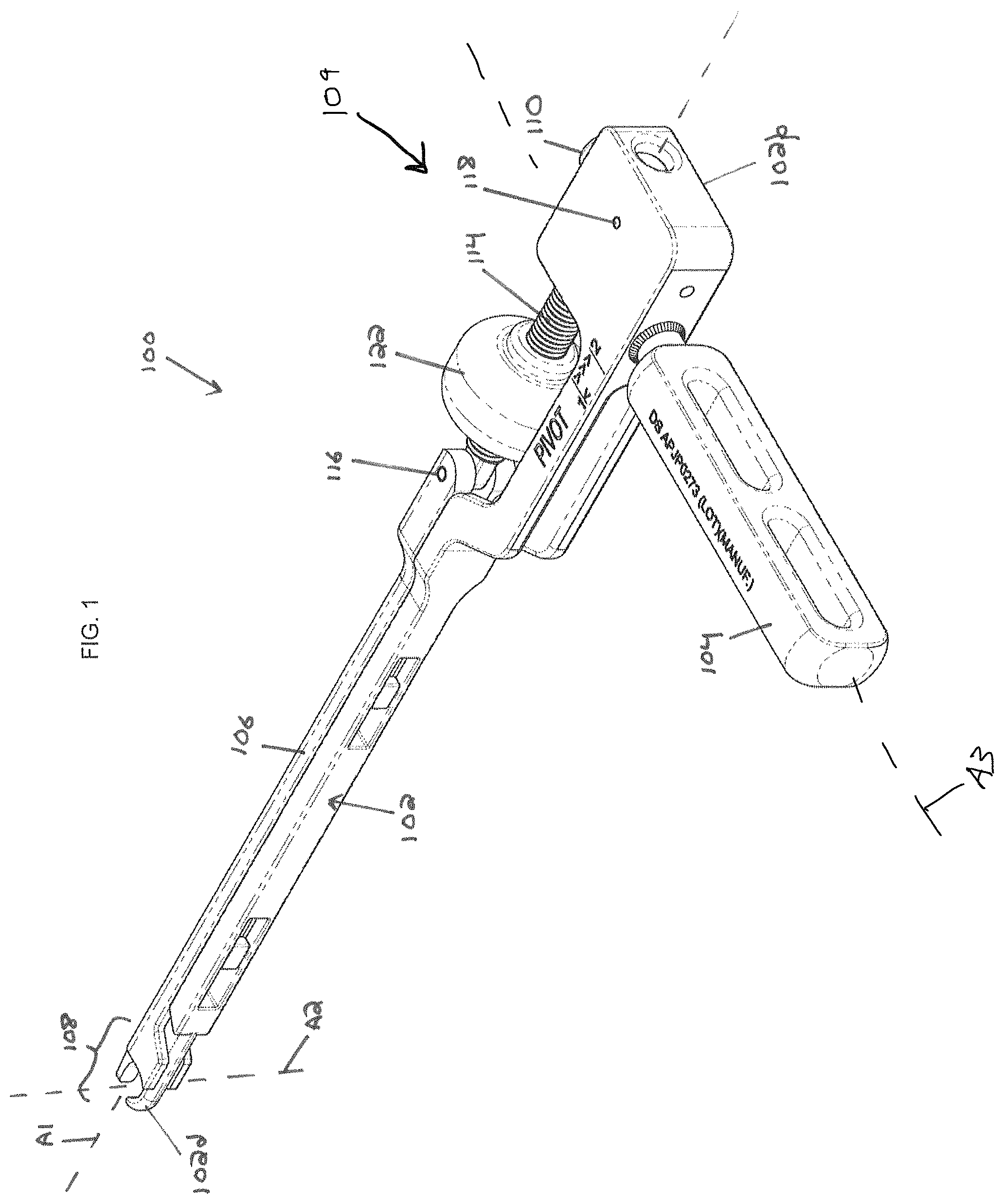
FIGS. 1-3 illustrate an exemplary implant inserter instrument 100. The instrument 100 can be used to insert an implant into a target location within a patient, such as a spinal disc space. The instrument 100 can be used to articulate or rotate the implant, or to allow the implant to be articulated or rotated, while the implant is disposed in the target location, or as the implant is delivered to the target location. The instrument 100 can allow the implant to rotate relative to the instrument while the implant remains captured or retained by the instrument. Exemplary implants with which the instrument 100 can be used include the T-PAL TLIF spacer available from DEPUY SYNTHES SPINE of Raynham, Mass. An example of this implant 5200 is shown in FIG. 52.
The instrument 100 can include a body 102 that extends from a proximal end 102p to a distal end 102d along a central longitudinal axis A1 of the instrument 100. The body 102 can include a handle or grip 104 extending therefrom. A slider 106 can be slidably coupled to the body 102 such that the slider can translate along the axis A1 relative to the body. The distal ends of the slider 106 and the body 102 can collectively define an implant clamp 108 configured to selectively grasp, capture, and/or retain an implant. The clamp 108 can be configured to selectively hold an implant while permitting articulation of the implant about an axis A2. The axis A2 can be perpendicular to the axis A1 and can extend between superior and inferior bone-contacting surfaces of the implant.
The proximal end of the slider 106 can be coupled to the body 102 via a locking mechanism 109. The locking mechanism 109 can have a first position in which the locking mechanism does not restrict axial translation of the slider 106 relative to the body 102, and a second position in which the locking mechanism limits axial translation of the slider relative to the body. The locking mechanism 109 can include a push button or other actuator 110 biased by a spring or other biasing element 112 and a locking shaft 114 disposed through an aperture formed in the button. The locking shaft 114 can be pivotally coupled to the slider 106 by a first pin 116. The button 110 can be slidably retained to the body 102 by a second pin 118. Pressing the button 110 into the body 102 against the bias of the spring 112 can move the button out of engagement with a groove 120 formed in the locking shaft 114, allowing the shaft and the slider 106 to translate axially or proximally/distally relative to the button and the body. Releasing the button 110 can allow the button to return under the bias of the spring 112 into engagement with the groove 120 formed in the shaft 114 to limit axial translation of the shaft and the slider 106 relative to the button and the body 102.
The instrument 100 can include an actuation knob or other actuator 122. The actuation knob 122 can be mounted to the locking shaft 114. For example, the actuation knob 122 can define a central opening having interior threads that mate with exterior threads formed on the locking shaft 114. As described further below, the actuation knob 122 can be movable along the locking shaft 114 between a first position in which an implant disposed in the clamp 108 is locked from rotating relative to the instrument 100 about the axis A2 and a second position in which such an implant is retained to the instrument but allowed to rotate relative to the instrument about the axis A2.
As shown in FIG. 4, the instrument 100 can be disassembled, e.g., for cleaning or sterilization. To disassemble the instrument 100, the actuation knob 122 can be rotated relative to the locking shaft 114 to move the knob along the locking shaft to a distal position. The button 110 can be depressed and the locking shaft 114 can be pulled distally out of the button and the body 102. The slider 106 can pivot about the first pin 116 to separate the slider from the body 102. The instrument 100 can thus be divided into a slider sub-assembly, e.g., including the slider 106, the locking shaft 114, and the actuation knob 122, and a body sub-assembly, e.g., including the body 102, the grip 104, the button 110, and the spring 112.
As shown in FIG. 5, the instrument 100 can be positioned in an implant loading configuration in which it is prepared to receive an implant in the clamp 108. To position the instrument 100 in this configuration, the button 110 can be depressed to allow the slider sub-assembly to translate axially or proximally/distally relative to the body 102. The actuation knob 122 can then be pulled proximally to translate the slider 106 relative to the body 102 along the axis A1, thereby opening the implant clamp 108, i.e., positioning the distal end of the slider 106 far enough proximally to permit a portion of an implant to be received within a concave distal portion of the body 102. For example, the illustrated implant 5200 of FIG. 52 includes a first surface 5202 and a second surface 5204 separated from one another. A post 5206 extends between the two surfaces and can be configured to be received or surrounded by the implant clamp 108 to couple the implant to the instrument 100. As shown in FIG. 52, the post 5206 can include a plurality of flat surfaces arranged around its circumference and, in some embodiments, these surfaces can be aid in the selective prevention of rotation of the implant relative to the instrument by, for example, including one or more corresponding flat surfaces on distal ends of any of the body 102 or slider 106 such that a flat surface of the instrument can be abutted against a flat surface of the implant to prevent relative movement therebetween. In other embodiments, however, curved surfaces can be utilized in any of the implant, body, and slider.
As shown in FIG. 6, once an implant (e.g., implant 5200) is positioned within the clamp 108, the slider 106 can be translated distally relative to the body 102 along the axis A1 to capture the implant within the clamp 108. In this configuration, the button 110 can be released such that the button engages the groove 120 formed on the locking shaft 114 to limit proximal movement of the slider 106 relative to the body 102 and to thereby retain the implant within the clamp 108.
As shown in FIGS. 6-7, the implant can be selectively permitted to rotate relative to the instrument 100 about the axis A2 when the implant is retained within the clamp 108. In particular, as shown in FIG. 6, the actuation knob 122 can be disposed in a first, proximal position in which an implant disposed in the clamp 108 is locked from rotating relative to the instrument 100 about the axis A2. To lock the implant from rotating relative to the instrument 100, the actuation knob 122 can be disposed in a proximal position on the locking shaft 114 in which the actuation knob abuts the body 102 to interfere with proximal translation of the slider 106 relative to the body. With the slider 106 urged distally and prevented from translating proximally, the implant can be firmly clamped to the instrument 100 such that the implant cannot rotate relative to the instrument about the axis A2. As shown in FIG. 7, the actuation knob 122 can be disposed in a second, distal position in which an implant disposed in the clamp 108 is retained to the instrument 100 but allowed to rotate relative to the instrument about the axis A2. The actuation knob 122 can be disposed in a distal position in which the actuation knob does not interfere with proximal translation of the slider 106 relative to the body 102. The groove 120 formed in the locking shaft 114 can be oversized in the proximal-distal direction relative to the engagement features of the button 110, such that some proximal movement of the slider 106 relative to the body 102 is permitted to allow articulation of the implant. The relative geometries of the button 110 and the groove 120, however, can be such that proximal translation of the slider 106 relative to the body 102 is not permitted to a degree that would allow the implant to separate from the instrument 100. As shown in FIG. 8, the instrument 100 can be configured such that a high degree of rotation of the implant about the axis A2 is permitted.
As shown in FIG. 9, the instrument 100 can be disconnected from the implant, e.g., once the implant is placed as desired within the patient. The instrument 100 can be separated from the implant by pressing the button 110 and pulling the actuation knob 122 proximally to translate the slider 106 proximally relative to the body 102 and thereby open the clamp 108, similar to the configuration shown in FIG. 5 for loading the implant prior to insertion into a patient.
FIGS. 10-51 illustrate detailed views of the various components of the instrument 100. FIG. 52 illustrates an exemplary implant that can be used with the instrument 100.
FIGS. 10-12, for example, show detailed side views of the instrument 100, including the proximal portion of the boxy 102. In these figures, the actuation knob 122 is shown positioned distally beyond the pivot positioning marker 1002. When the knob is in such a position and the button 110 is depressed, the slider 106 can be advanced distally and rotated about pin 116 away from the body 102, as shown in FIG. 4. Conversely, when full locking of the implant within the clamp 108 is desired, the actuation knob 122 can be positioned proximally such that it abuts against the body 102 and is in line with the lock positioning marker 1004.
FIGS. 13-16 illustrate the above-mentioned slider sub-assembly 1300, which can include the slider 106, locking shaft 114, pin 116, and actuation knob 122. The slider 106 can be coupled to the locking shaft 114 using a clevis joint, e.g., with a proximal end of the slider 106 forming a U-shaped clevis with opposed arms 1402, 1404 that receive a tang 1406 formed at a distal end of the locking shaft 114. The components can be held together by the pin 116 such that they can pivot about the pin's longitudinal axis but cannot rotate relative to one another about a central longitudinal axis of the slider or locking shaft.
The slider 106 can include a distal end 1408 configured to form part of the clamp 108, as well as distal guide surfaces 1302, 1304 configured to ride along the sides of an elongate distal portion of the body 102 to maintain alignment of the slider and the body. The slider 106 can also include one or more protrusions 1306, 1308 configured to be received within recesses formed in the body 102 to maintain alignment of the slider and the body and prevent inadvertent pivoting of the components away from one another. The protrusions 1306, 1308 can have any of a variety of shapes but in some embodiments can have a T-track or other shape that can be received through a larger opening and subsequently translated into a smaller opening to prevent separation but allow for translation between the slider and the body.
As noted above, the locking shaft 114 can include the groove 120 formed in a proximal portion thereof, as well as the aforementioned distal end 1406 configured to couple to the proximal end of the slider 106. A portion of the locking shaft 114 between the groove 120 and the distal end 1406 can have external threads 1310 formed thereon. The external threads 1310 can be configured to mate with threads formed on an internal surface of a central opening formed in the actuation knob 122 to allow rotation of the knob to control translation of the slider 106 relative to the body 102, as described herein.
FIGS. 17-20 illustrate the above-mentioned body subassembly 1700, which can include the body 102, grip or handle 104, button or other actuator 110, and spring or other biasing element 112. The grip or handle 104 can be coupled to the body 102 in a variety of manners, including via a threaded connection, a press fit interference connection, welding, adhesive, etc. The handle 104 can extend from the body 102 such that a longitudinal axis A3 of the handle is perpendicular to the central longitudinal axis A1 of the instrument. Alternatively, the handle 104 can be arranged to extend from at a different angle such that the axes A3 and A1 cross one another at an oblique angle.
The push button or other actuator 110 can be disposed in a first bore (see FIG. 21) formed in the body 102 along with the spring or other biasing element 112. The pin 118 can retain the button 110 within the first bore while allowing movement through a desired range of motion. As explained in more detail below, the button 110 can include an aperture formed therein that can at least partially align with a second bore formed in the body 102 to receive the locking shaft 114.
FIGS. 21-26 illustrate the body 102 in greater detail. A distal portion of the body 2106 can have a shape to receive a portion of an implant, such as the implant 5200 of FIG. 52. The portion 2106 can, for example, have a curved semi-circular shape that can receive a portion of an implant and, in connection with a correctly-positioned distal portion of the slider 106, retain the implant between the slider and the body.
The distal portion 2106 can be disposed at an end of an elongate distal portion 2104 of the body 102 that extends from a proximal portion 2102. Spaced along the elongate distal portion 2104 can be one or more apertures 2108, 2110 configured to receive the one or more protrusions 1306, 1308 formed on the slider 106. Each aperture, e.g., aperture 2108, can include a larger distal opening 2108a configured to receive the protrusion 1306 when the slider is pivoted into parallel alignment with the body 102, as well as a narrower proximal opening 2108b configured to receive only a narrower portion of the protrusion 1306 (e.g., when the protrusion has a T shape, etc.) to permit translation of the slider relative to the body while preventing the slider from pivoting away from the body. A cross-sectional view of a shoulder 2402 that can be used to achieve this effect is shown in FIG. 24.
Turning to the proximal portion 2102 of the body 102, FIGS. 21-26 illustrate the first bore 2112 that is configured to receive the push button 110 and spring 112. Also shown is the second bore 2202 that is configured to receive the locking shaft 114. The first and second bores 2112, 2202 cross one another such that the locking shaft 114 can extend through an aperture formed in the button 110. Also shown in the figures is a third bore 2204 formed in the body 102 and configured to receive an end of the handle or grip 104.
FIGS. 27-36 illustrate the slider 106 in greater detail. Visible features include the T-shaped protrusions 1306, 1308, the proximal clevis U-shaped arms 1402, 1404, the distal guides 1302, 1304, and the distal end 1408 described above. Of note in these figures is the fact that the guides 1302, 1304 can be configured to contact the portion of the implant disposed between distal ends of the slider 106 and the body 102 in the implant clamp 108. Accordingly, the guides 1302, 1304 can provide additional surface area for securely gripping the implant and preventing any relative movement, e.g., rotation, of the implant relative to the instrument 100 when in the locked configuration shown in FIG. 6.
FIG. 37 illustrates the grip or handle 104 in isolation, including a protrusion 3702 formed at one end thereof that can be configured to extend into the bore 2204 and be secured using any of a variety of techniques known in the art. Also shown is the central longitudinal axis A3 of the handle 104 that can be configured to extend from the instrument such that it is perpendicular to the central longitudinal axis of the instrument A1, as shown in FIG. 1. In other embodiments, however, the handle can be configured to extend at a different angle from the body 102 such that the axes A1, A3 are oblique to one another.
FIGS. 38-40 illustrate the locking shaft 114 in isolation. Visible in the figure are the above-described distal tang 1406, the proximal groove 120, and the intermediate portion having external threads 1310 formed thereon. As noted above, the groove 120 can have an oversize length L extending axially along the shaft to allow some degree of proximal/distal translation of the shaft relative to the body even when the button 110 is positioned so as to retain the shaft to the body 102.
FIGS. 41-43 illustrate the actuation knob 122 in isolation. As noted above, the actuation knob 122 can include a central opening 4102 formed therein and an internal surface of the opening can include threads 4104 formed thereon. The threads 4104 can be configured to mate with the external threads 1310 formed on the locking shaft 114, as described herein. An outer surface of the actuation knob 122 can include surface features to facilitate a user gripping and rotating the knob, such as surface knurling 4302 or other similar features.
FIGS. 44-48 illustrate various views of the push button or other actuator 110. The button 110 can include an aperture formed therethrough that can be configured to receive the locking shaft 114. The aperture can have a first circular diameter D.sub.1 extending through an entire thickness of the button 110, as well as partial-thickness cut-outs extending from each end of the aperture having a larger elliptical shape with major diameter D.sub.2 and a minor diameter of D.sub.1. This can create an aperture or through-hole having a ridge 4404 extending into the aperture or through-hole 4402. The ridge 4404 can have a size configured to interface with the groove 120 formed in the locking shaft 114 such that, when the ridge 4404 is disposed within the groove 120, the locking shaft can only be moved proximally or distally until the ridge abuts one of a proximal or distal sidewall of the groove 120. Because the ridge is formed on the bottom of the aperture 4402, the biasing element 112 can urge the button 110 upward and urge the ridge 4404 into the groove 120 when a user releases the button 110. Conversely, when a user depresses the button 110 and disposes the locking shaft 114 in the upper portion of the aperture 4402 above the ridge 4404, the locking shaft 114 can be withdrawn from the aperture 4402.
The upward or downward travel of the button 110 can be limited by the pin 118 that can be disposed within a second aperture 4502 formed through the button 110. As shown, the second aperture 4502 is perpendicularly oriented relative to the aperture 4402, but in other embodiments a different configuration can be utilized. The second aperture 4502 can have an elliptical cross section with a major diameter that can define the range of movement for the button 110 (because the pin 118 can be stationary relative to the body 102 when disposed through apertures formed therein that substantially match the diameter of the pin). This dimension can be configured to substantially match, for example, a depth of the groove 120 and height of the ridge 4404 in some embodiments.
FIGS. 49-51 illustrate the spring 112 and pins 116, 118 in isolation. These components are known in the art, e.g., conventional coil springs and cylindrical pins. In some embodiments, any of a variety of alternatives known in the art can be substituted for the elements shown in these figures.
In use, the instrument 100 can be configured as shown in FIG. 4 and can be cleaned and/or sterilized to prepare the instrument for surgery. A fusion cage or other implant can be loaded onto the instrument 100 and locked in the position shown in FIG. 6. The instrument 100 can then be used to deliver the implant to a target site within a patient, for example by passing the implant into a spinal disc space through a minimally-invasive working channel and/or using a TLIF approach. Once the implant is disposed within the disc space, or at any other time desired by the user, the instrument 100 can be configured as shown in FIG. 7 and the implant can be rotated relative to the instrument about the axis A2, e.g., to either of the positions shown in FIGS. 7 and 8. The instrument 100 can then be disconnected from the implant as shown in FIG. 9, and the surgical procedure can be completed using known techniques.
It should be noted that any ordering of method steps expressed or implied in the description above or in the accompanying drawings is not to be construed as limiting the disclosed methods to performing the steps in that order. Rather, the various steps of each of the methods disclosed herein can be performed in any of a variety of sequences. In addition, as the described methods are merely exemplary embodiments, various other methods that include additional steps or include fewer steps are also within the scope of the present disclosure.
The instruments disclosed herein can be constructed from any of a variety of known materials. Exemplary materials include those which are suitable for use in surgical applications, including metals such as stainless steel, titanium, nickel, cobalt-chromium, or alloys and combinations thereof, polymers such as PEEK, ceramics, carbon fiber, and so forth. The various components of the instruments disclosed herein can be rigid or flexible. Device sizes can also vary greatly, depending on the intended use and surgical site anatomy. Furthermore, particular components can be formed from a different material than other components. One or more components or portions of the instruments can be formed from a radiopaque material to facilitate visualization under fluoroscopy and other imaging techniques, or from a radiolucent material so as not to interfere with visualization of other structures. Exemplary radiolucent materials include carbon fiber and high-strength polymers.
The instruments and methods disclosed herein can be used in minimally-invasive surgery and/or open surgery. While the instruments and methods disclosed herein are generally described in the context of spinal surgery on a human patient, it will be appreciated that the methods and instruments disclosed herein can be used in any type of surgery on a human or animal subject, in non-surgical applications, on non-living objects, and so forth.
The devices disclosed herein can be designed to be disposed after a single use, or they can be designed for multiple uses. In either case, however, the device can be reconditioned for reuse after at least one use. Reconditioning can include any combination of the steps of disassembly of the device, followed by cleaning or replacement of particular pieces, and subsequent reassembly. In particular, the device can be disassembled, and any number of the particular pieces or parts of the device can be selectively replaced or removed in any combination. Upon cleaning and/or replacement of particular parts, the device can be reassembled for subsequent use either at a reconditioning facility or by a surgical team immediately prior to a surgical procedure. Those skilled in the art will appreciate that reconditioning of a device can utilize a variety of techniques for disassembly, cleaning/replacement, and reassembly. Use of such techniques, and the resulting reconditioned device, are all within the scope of the present invention.
The devices described herein can be processed before use in a surgical procedure. First, a new or used instrument can be obtained and, if necessary, cleaned. The instrument can then be sterilized. In one sterilization technique, the instrument can be placed in a closed and sealed container, such as a plastic or TYVEK bag. The container and its contents can then be placed in a field of radiation that can penetrate the container, such as gamma radiation, x-rays, or high-energy electrons. The radiation can kill bacteria on the instrument and in the container. The sterilized instrument can then be stored in the sterile container. The sealed container can keep the instrument sterile until it is opened in the medical facility. Other forms of sterilization known in the art are also possible. This can include beta or other forms of radiation, ethylene oxide, steam, or a liquid bath (e.g., cold soak). Certain forms of sterilization may be better suited to use with different portions of the device due to the materials utilized, the presence of electrical components, etc.
All papers and publications cited herein are hereby incorporated by reference in their entirety. Although specific embodiments are described above, it should be understood that numerous changes may be made within the spirit and scope of the concepts described. Accordingly, the disclosure is not to be limited by what has been particularly shown and described, except as indicated by the appended claims.
* * * * *
References
D00000
D00001
D00002
D00003
D00004
D00005
D00006
D00007
D00008
D00009
D00010
D00011
D00012
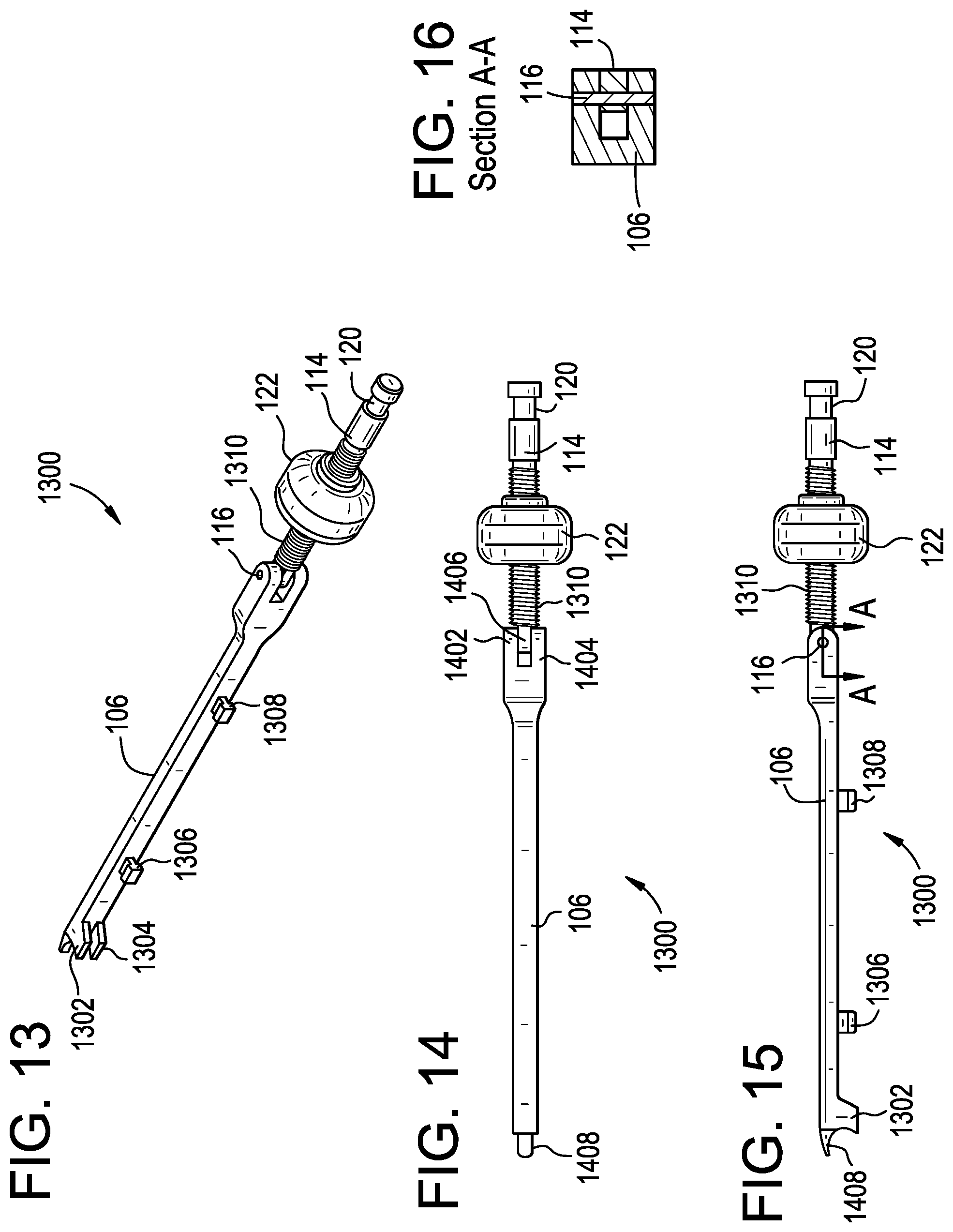
D00013

D00014

D00015

D00016

D00017

D00018
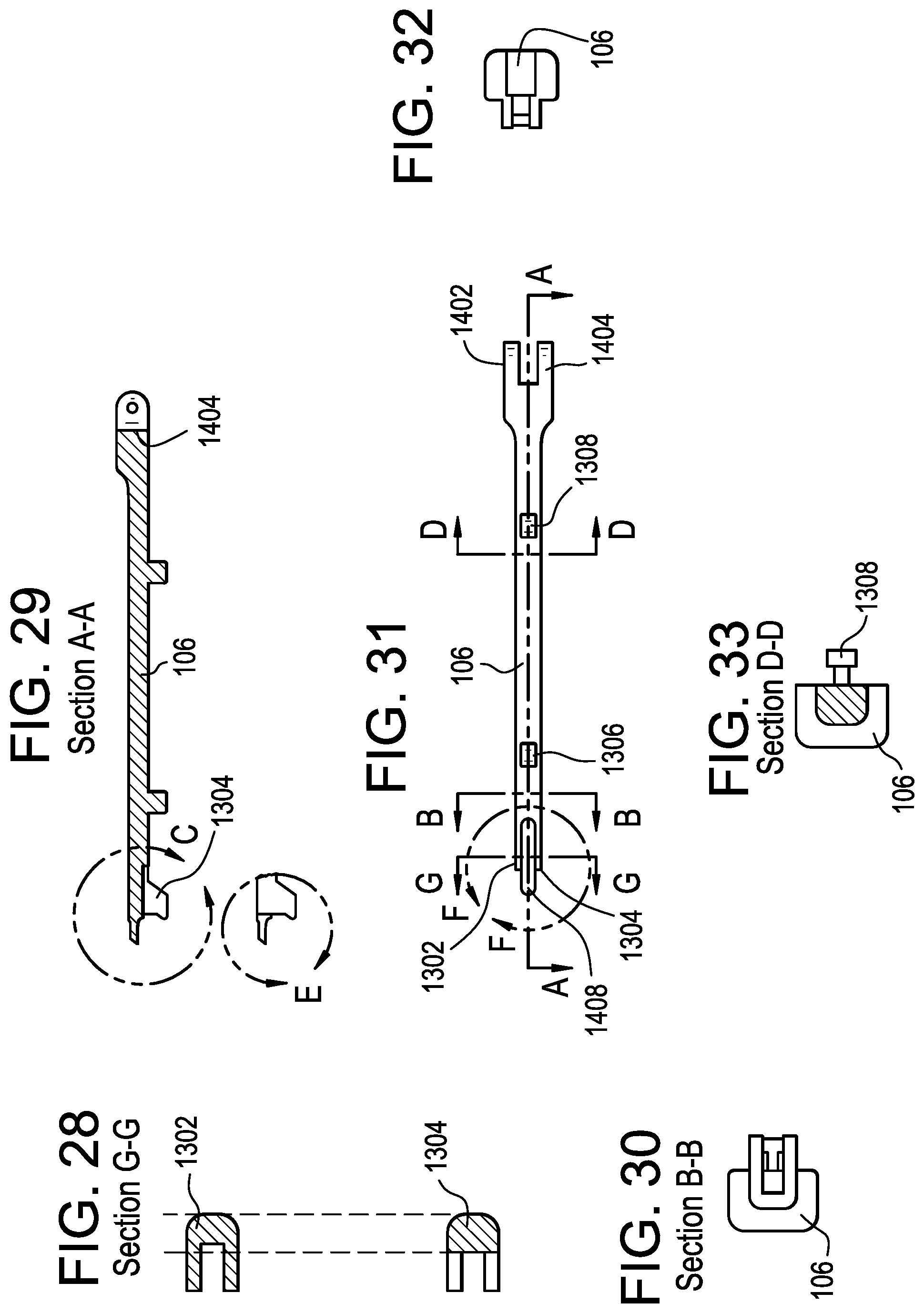
D00019

D00020

D00021

D00022

XML
uspto.report is an independent third-party trademark research tool that is not affiliated, endorsed, or sponsored by the United States Patent and Trademark Office (USPTO) or any other governmental organization. The information provided by uspto.report is based on publicly available data at the time of writing and is intended for informational purposes only.
While we strive to provide accurate and up-to-date information, we do not guarantee the accuracy, completeness, reliability, or suitability of the information displayed on this site. The use of this site is at your own risk. Any reliance you place on such information is therefore strictly at your own risk.
All official trademark data, including owner information, should be verified by visiting the official USPTO website at www.uspto.gov. This site is not intended to replace professional legal advice and should not be used as a substitute for consulting with a legal professional who is knowledgeable about trademark law.