Universal Trial for Lateral Cages
O'Neil; Michael J. ; et al.
U.S. patent application number 13/163397 was filed with the patent office on 2011-12-29 for universal trial for lateral cages. Invention is credited to Jonathan Bellas, Cody Cranson, Sheryl Frank, Michael J. O'Neil, Michael Toto.
| Application Number | 20110319998 13/163397 |
| Document ID | / |
| Family ID | 45353243 |
| Filed Date | 2011-12-29 |


View All Diagrams
| United States Patent Application | 20110319998 |
| Kind Code | A1 |
| O'Neil; Michael J. ; et al. | December 29, 2011 |
Universal Trial for Lateral Cages
Abstract
A method of trialing an intervertebral disc space, comprising the steps of: a) creating the disc space, b) inserting a trial into the disc space, the trial having i) a distal head having an upper surface and a lower surface connected by a pair of side walls, the side walls defining planes, and ii) a proximal rod, wherein the head and rod form an obtuse angle, and wherein the rod extends through at least one of the planes defined by the side walls of the head.
| Inventors: | O'Neil; Michael J.; (Raynham, MA) ; Bellas; Jonathan; (Raynham, MA) ; Cranson; Cody; (Raynham, MA) ; Frank; Sheryl; (Raynham, MA) ; Toto; Michael; (Raynham, MA) |
| Family ID: | 45353243 |
| Appl. No.: | 13/163397 |
| Filed: | June 17, 2011 |
Related U.S. Patent Documents
| Application Number | Filing Date | Patent Number | ||
|---|---|---|---|---|
| 61358220 | Jun 24, 2010 | |||
| 61379194 | Sep 1, 2010 | |||
| 61385958 | Sep 23, 2010 | |||
| 61410177 | Nov 4, 2010 | |||
| 61397716 | Nov 30, 2010 | |||
| 61466302 | Mar 22, 2011 | |||
| Current U.S. Class: | 623/17.16 |
| Current CPC Class: | A61F 2002/30593 20130101; A61M 25/0054 20130101; A61B 2017/0256 20130101; A61F 2002/30523 20130101; A61M 25/0133 20130101; A61F 2/4603 20130101; A61F 2/30771 20130101; A61F 2/446 20130101; A61M 29/02 20130101; A61F 2/4465 20130101; A61F 2002/30326 20130101; A61F 2/4425 20130101; A61F 2/447 20130101; A61B 17/1659 20130101; A61F 2/4637 20130101; A61B 5/4893 20130101; A61B 17/1671 20130101; A61B 17/1757 20130101; A61F 2/4611 20130101; A61B 2017/3433 20130101; A61F 2/4455 20130101; A61F 2002/443 20130101 |
| Class at Publication: | 623/17.16 |
| International Class: | A61F 2/44 20060101 A61F002/44 |
Claims
1. An intervertebral trial for assessing an intervertebral disc space, comprising: a) a distal head having an upper surface and a lower surface, the surfaces adapted for contacting opposed vertebral endplates; b) a sheath having a longitudinal throughbore, a distal end portion pivotally connected to the distal head, and a proximal end portion; c) a rod disposed in the throughbore and having a distal end portion pivotally connected to the distal head and a threaded portion, d) a knob abutting the proximal end portion of the sheath and threadably connected to the threaded portion of the rod, wherein rotation of the knob moves the rod longitudinally to pivot the distal head about the rod.
2. The trial of claim 1 wherein the knob comprises an outer surface having at least one indicator that indicates a degree of angulation provided by the trial.
3. An intervertebral trial for assessing an intervertebral disc space, comprising: a) a distal head having an upper surface, a lower surface, and a pair of side surfaces connecting the upper and lower surfaces; the pair of side surfaces defining a pair of planes; b) a sheath having a longitudinal throughbore and having a distal end portion pivotally connected to the distal head, c) a rod disposed in the throughbore and having a distal end portion pivotally connected to the distal head and a proximal end portion, wherein longitudinal movement of the rod pivots the rod between the pair of planes of the sidewalls of the distal head.
4. The trial of claim 3 further comprising: d) a knob threadably connected to the proximal end portion of the rod, wherein rotation of the knob urges the rod longitudinally to pivot the distal head.
5. An intervertebral trial for assessing an intervertebral disc space, comprising: a) a distal head having an upper surface, a lower surface, and a proximal end portion comprising a substantially spherical element; b) a sheath having a throughbore having a proximal end portion, c) a rod disposed in the throughbore, the rod having a distal end portion forming a collet, a intermediate portion, and a proximal end portion, wherein the intermediate portion of the rod mates with the proximal end portion of the throughbore of the sheath, wherein the substantially spherical element of the distal head is rotatably received in the collet to form a universal joint.
6. The trial of claim 5 wherein rotation of the proximal end portion of the rod causes the rod to retract.
7. The trial of claim 5 wherein the proximal end portion of the rod comprises a handle attachment element.
8. The trial of claim 5 wherein the distal head further comprises a pair of side surfaces connecting the upper and lower surfaces, and wherein the distal head is angled so that the rod extends through the planes formed by the side surfaces and the planes formed by the upper and lower surfaces.
9. The trial of claim 5 wherein retraction of the rod causes the collet to close upon the substantially spherical element, thereby locking a position of the distal head with respect to the rod.
10. An intervertebral trial for assessing an intervertebral disc space, comprising: a) a distal head having an upper surface, a lower surface, and a proximal end portion comprising a substantially spherical element; b) a sheath having a throughbore having a threaded portion, c) a rod disposed in the throughbore, the rod having a distal end portion forming a poppet, a threaded intermediate portion, and a proximal end portion, wherein the threaded intermediate portion of the rod threadably mates with the threaded portion of the sheath, wherein the substantially spherical element of the distal head is rotatably received in the poppet to form a universal joint.
11. The trial of claim 10 wherein the throughbore of the sheath has a distal end portion forming a concave lip for receiving the substantially spherical element.
12. The trial of claim 11 wherein the spherical element and lip form a tongue and groove construction.
13. The trial of claim 11 wherein rotation of the rod causes the rod to advance distally and the poppet to bias against the substantially spherical element, thereby locking a position of the distal head.
14. The trial of claim 10 wherein the proximal end portion of the rod forms a handle attachment.
15. An intervertebral trial for assessing an intervertebral disc space, comprising: a) a distal head having an upper surface, a lower surface, and a proximal end portion comprising a joint element; the upper and lower surfaces adapted to contact opposing vertebral endplates; b) a sheath having a longitudinal throughbore having a proximal end portion and a distal end portion, c) a rod disposed in the throughbore, the rod having a distal end portion mating with the joint element to form an articulating joint, an intermediate portion, and a proximal end portion, wherein the intermediate portion of the rod is received in the proximal end portion of the throughbore of the sheath, wherein longitudinal movement of the rod causes the distal end portion of the rod to bias against the joint element, thereby locking a position of the distal head with respect to the rod.
16. The trial of claim 15 wherein the intermediate portion of the rod is threaded, wherein the proximal portion of the sheath is threaded; and wherein the threaded intermediate portion of the rod threadably mates with the threaded proximal end portion of the sheath.
17. The trial of claim 15 wherein rotation of the rod causes the rod to advance and the the distal end portion of the rod to bias against the joint element, thereby locking a position of the distal head.
18. The trial of claim 15 wherein the proximal end portion of the rod forms a handle attachment.
19. The trial of claim 15 wherein the distal head further comprises a pair of side surfaces connecting the upper and lower surfaces, and wherein the distal head is angled with respect to the rod so that the rod is not located between planes formed by the side surfaces nor planes formed by the upper and lower surfaces.
20. The trial of claim 15 wherein the joint element of the distal head is a substantially spherical element, and the distal end portion of the rod forms a collet.
21. The trial of claim 15 wherein the distal end portion of the throughbore forms a lip having a concave surface.
22. An intervertebral trial for assessing an intervertebral disc space, comprising: a) a distal head having an upper surface and a lower surface; b) a sheath having a throughbore and having a distal end portion pivotally connected to the distal head, c) a rod disposed in the throughbore and having a distal end portion pivotally connected to the distal head and a threaded portion, d) a knob threadably connected to the threaded portion of the rod. wherein rotation of the knob moves the rod longitudinally to pivot the distal head, and wherein the knob comprises an outer surface having an indicator that indicates a degree of angulation provided by the trial.
23. A method of trialing an intervertebral disc space, comprising the steps of: a) inserting a trial into the disc space, the trial having i) a distal head having an upper surface and a lower surface, ii) a proximal rod, wherein the rod and distal head are pivotally connected, and wherein the head and rod form an obtuse angle when the distal head is in the disc space, and iii) an angulation indicator connected to the rod, b) rotating the rod to adjust the obtuse angle, and c) reading the angulation indicator on the trial.
24. The method of claim 23 wherein the angulation indicator comprises a knob connected to a proximal end portion of the rod.
25. A method of trialing an intervertebral disc space, comprising the steps of: a) inserting a trial into the disc space, the trial having i) a distal head having an upper surface and a lower surface, and ii) a proximal rod, wherein the head and rod form an obtuse angle .beta. when the head is in the disc space, wherein the rod extends substantially parallel to a pair of planes defined by the upper surface and the lower surface of the head when the head is in the disc space.
26. A method of trialing an intervertebral disc space, comprising the steps of: a) inserting a trial into the disc space, the trial having i) a distal head having an upper surface and a lower surface connected by a pair of side walls, the side walls defining a pair of planes, and ii) a proximal rod, wherein the head and rod form an obtuse angle when the head is in the disc space, wherein the rod extends through a first plane defined by the side walls of the head when the head is in the disc space.
27. A method of trialing an intervertebral disc space, comprising the steps of: a) inserting a trial into the disc space, the trial having i) a distal head having an upper surface and a lower surface connected by a pair of side walls, the side walls defining a pair of planes, and ii) a proximal rod, wherein the head and rod form an obtuse angle .gamma. when the head is in the disc space, wherein the rod extends substantially parallel to the pair of planes defined by the side walls of the head when the head is in the disc space.
28. A method of trialing an intervertebral disc space, comprising the steps of: a) inserting a trial into the disc space substantially within a coronal plane, the trial having i) a distal head having an upper surface and a lower surface connected by a pair of side walls, the side walls defining planes, and ii) a proximal rod, wherein the head and rod form an obtuse angle .gamma. in the coronal plane when the head is in the disc space.
29. A method of trialing an intervertebral disc space, comprising the steps of: a) substantially laterally inserting a trial into the disc space substantially within a transverse plane, the trial having i) a distal head having an upper surface and a lower surface connected by a pair of side walls, the side walls defining planes, and ii) a proximal rod, wherein the head and rod form an obtuse angle .beta. in the transverse plane when the head is in the disc space.
30. A method of trialing an intervertebral disc space, comprising the steps of: a) inserting a trial into the disc space, the trial having i) a distal head having an upper surface and a lower surface connected by a pair of side walls, the side walls defining a pair of planes, the upper and lower surfaces defining a pair of planes, and ii) a proximal rod, wherein the head and rod form an obtuse angle when the head is in the disc space, wherein the rod extends through one of the first pair of planes defined by the side walls of the head when the head is in the disc space, and wherein the rod extends through one of the second pair of planes defined by the upper and lower surfaces of the head when the head is in the disc space.
31. The method of claim 30 wherein the obtuse angle is between 1 and 45 degrees.
32. A method comprising the steps of: a) laterally inserting a variable-angle trial into an intervertebral disc space, b) determining an angle set by the trial in the disc space, c) providing the angle to an implant-inserter apparatus, d) inserting the implant into the disc space at the angle.
Description
CONTINUING DATA
[0001] This application claims priority from provisional application U.S. Ser. No. 61/466,302, filed Mar. 22, 2011, entitled Universal Trial for Lateral Cages, (Attorney Docket No. DEP6390USPSP), the specification of which is incorporated by reference in its entirety.
[0002] This application claims priority from provisional application U.S. Ser. No. 61/358,220, filed Jun. 24, 2010, entitled Instruments and Methods for Non-Parallel Disc Space Preparation, (Attorney Docket No. DEP6322USPSP), and is related to non-provisional U.S. Ser. No. ______, filed on even date, entitled Instruments and Methods for Non-Parallel Disc Space Preparation (Attorney Docket No. DEP6322USNP), the specifications of which are incorporated by reference in their entireties.
[0003] This application claims priority from U.S. Ser. No. 61/379,194, filed on Sep. 1, 2010, and entitled "Flexible Vertebral Body Shavers" (DEP6323USPSP), and is related to non-provisional U.S. Ser. No. ______, filed on even date, entitled "Flexible Vertebral Body Shavers" (DEP6323USNP), the specifications of which are incorporated by reference in their entireties.
[0004] This application claims priority from provisional application U.S. Ser. No. 61/385,958, filed Sep. 23, 2010, and entitled "Multi-Segment Lateral Cages adapted to Flex Substantially in the Coronal Plane" (DEP6342USPSP), the specification of which is incorporated by reference in its entirety.
[0005] This application claims priority from provisional application U.S. Ser. No. 61/410,177, filed Nov. 4, 2010, and entitled "Multi-Segment Lateral Cages adapted to Flex Substantially in the Coronal Plane" (DEP6342USPSP2), the specification of which is incorporated by reference in its entirety.
[0006] This application is related to non-provisional U.S. Ser. No. ______, filed on even date, entitled "Multi-Segment Lateral Cages adapted to Flex Substantially in the Coronal Plane" (DEP6342USNP), the specification of which is incorporated by reference in its entirety.
[0007] This application claims priority from provisional application U.S. Ser. No. 61/397,716, filed Nov. 30, 2010, and entitled "Lateral Spondylolisthesis Reduction Cage" (DEP6345USPSP), and is related to non-provisional U.S. Ser. No. ______, filed on even date, entitled "Lateral Spondylolisthesis Reduction Cage" (DEP6345USNP), the specifications of which are incorporated by reference in their entireties.
BACKGROUND OF THE INVENTION
[0008] In spine surgery, lateral access approaches are increasingly used to deliver interbody fusion cages to the lumbar spine. These lateral approaches are gaining in popularity because they minimize posterior and/or anterior tissue damage, as well as reduce operating room time and associated blood loss, and infection risk. Conventional lateral approaches include the following: Direct Lateral (transpsoas entry parallel cranially and caudally with the disc space, or retract the psoas); Anterior-Lateral (anterior to the psoas parallel to the disc space); and Superior/Inferior Lateral (non-parallel lateral access to the disc space). See instruments A-C in FIGS. 1-5.
[0009] The use of multiple lateral approaches has required the development of a trialing system for each approach, thus increasing the number of surgical instruments and overall procedure cost. Specifically-angled trials limit the surgical approaches to the single specific angle of the trial.
[0010] Currently, no conventional trial system allows for determination of the angle of the implanted trial following its satisfactory placement and imaging.
[0011] US Patent Publication No. 2008-0077241 (Nguyen) discloses a method of preparing a pair of adjacent vertebral endplates, involving a surgical instrument having a pivoting distal removable insert, a proximal handle portion, a body portion, and a linkage member positioned between the insert and the proximal handle portion, the insert having a first angular position relative to the body. A leading end of the insert may be placed in a first position between two adjacent vertebral endplates and moved to a second position between the adjacent vertebral endplates by impacting the proximal end portion of the surgical instrument. The insert may be pivoted to a second angular position relative to the body portion by rotating the handle about the body portion and may lock the second angular position of the distal insert. The insert may be moved to a third position between the adjacent vertebral endplates by impacting the proximal end portion of the surgical instrument.
[0012] US Patent Publication No. 2008-0065082 (Chang) discloses instruments and methods for inserting a rasp into an intervertebral space of a spine and using the rasp to decorticate the adjacent vertebra. More particularly, one embodiment provides an instrument that actively changes the angle of the rasp relative to the instrument. The delivery instrument may use a gear portion to articulate the rasp. A second gear on the rasp may mate with a corresponding gear on the instrument. As the instrument gear rotates relative to the instrument, the instrument gear drives the rasp gear, thereby rotating the rasp to decorticate the vertebra. Trial inserts and methods are also provided to determine an appropriate size of a rasp for decortication.
[0013] US Patent Publication No. 2008-0140085 (Gately) discloses a method to insert a spinal implant into a vertebral space, the method including the steps of: grasping the implant with a distal end of an implant insertion tool; holding a proximal end of the implant insertion tool and inserting the implant toward the vertebral space; and manipulating the proximal end to apply a yaw movement to the implant while the implant is attached to the tool and in the vertebral space.
[0014] Adjustable TLIF implant inserters are limited in angulation to the axial plane for posterior approach surgeries. These devices do not measure the amount of angulation instilled in the trial. Therefore, there remains a need for adjustable trials that allow for flexion of angles of insertion and measurement of the insertion angle for a lateral trial.
SUMMARY OF THE INVENTION
[0015] Several devices and methods are disclosed for inserting lateral trials at trajectories skewed from the intervertebral disc space. Each trial incorporates means to enable controlled angulations into the prepared disc space. These means include bending or pivoting means. Angulations can be performed intra-operatively (on a mayo stand) or in-situ (during or following insertion into the disc). The trial also allows for measurement of the insertion approach/angle to help ensure the implant is inserted at a consistent angle.
[0016] Continuously adjustable trials allow for flexible and adaptable angles of approach based upon patient anatomy, surgical preference and numbers of levels to be fused.
DESCRIPTION OF THE FIGURES
[0017] FIG. 1 discloses the conventional paths of direct lateral and anterior-lateral access to a disc space.
[0018] FIGS. 2 and 3 disclose lines of sight for direct lateral access to the disc space, wherein the trajectory is substantially parallel to the disc space.
[0019] FIGS. 4a and 4b disclose lines of sight for indirect lateral access to the disc space, wherein the trajectory is substantially skewed with respect to the disc space.
[0020] FIG. 5 discloses a trial inserted into the disc space via a straightforward lateral approach.
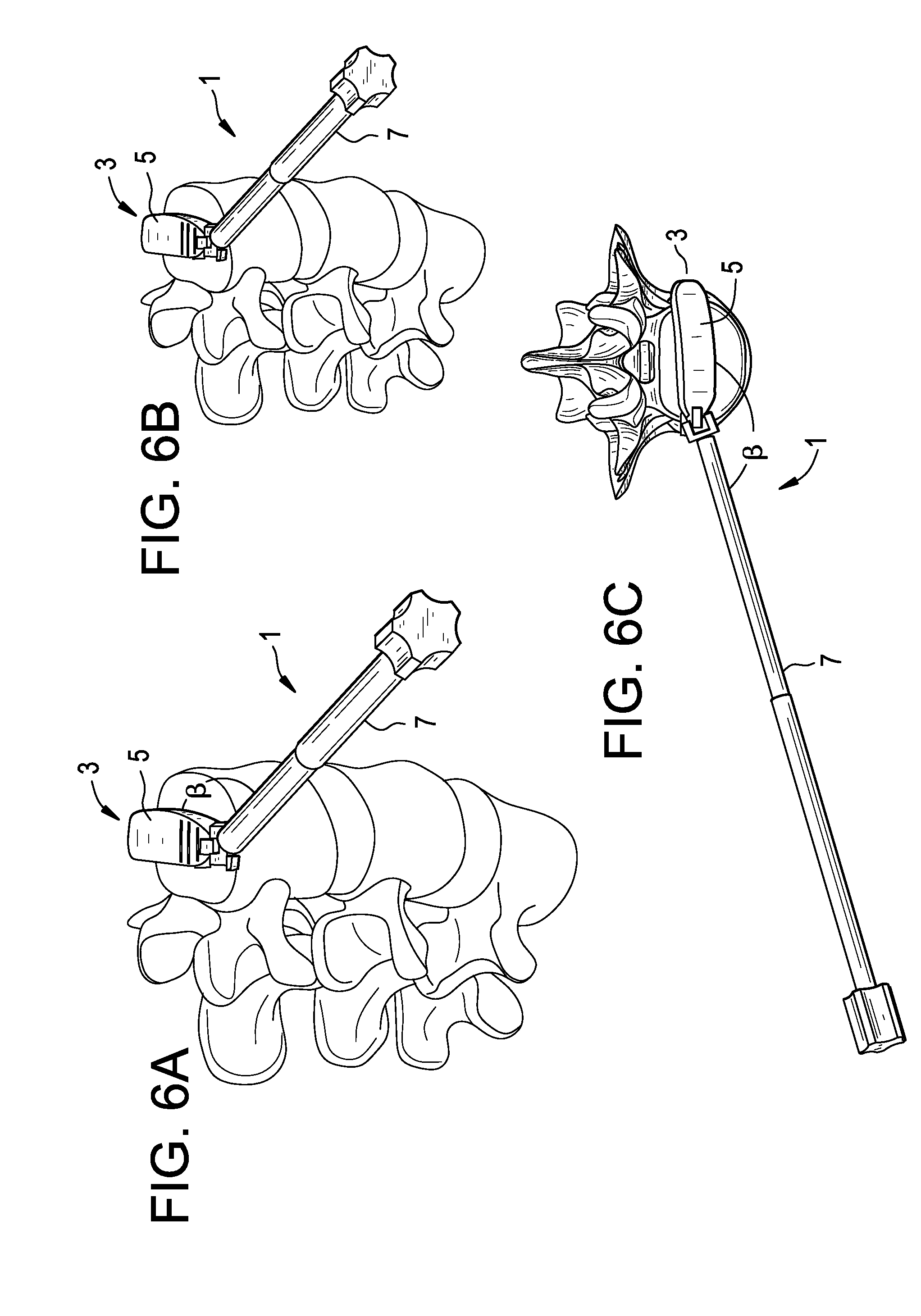
[0021] FIGS. 6a-6c disclose an angled trial inserted into the disc space via an anterior-lateral approach, wherein the trial is angled in the transverse plane.
[0022] FIGS. 7a-7b disclose angled trials inserted into the disc space via an superior-lateral and inferior-lateral approaches, wherein the trials are angled in the coronal plane.
[0023] FIGS. 8a-8b disclose side views of angled trials wherein the distal head pivots about the sheath.
[0024] FIG. 8c discloses a cross-sectional view of an angled trial wherein the distal head pivots about the sheath.
[0025] FIG. 8d is a side view of the pivoting portion of the trial of FIG. 8a.
[0026] FIG. 8e discloses a cross-sectional view of the proximal end portion of the angled trial of FIG. 8c.
[0027] FIGS. 9a-9d disclose side views of angled trials wherein the distal head pivots about the sheath in the coronal plane, wherein the trials have varying degrees of angulation.
[0028] FIG. 10a discloses a first embodiment of a universal trial having a conical range of angulation.
[0029] FIG. 10b discloses a close-up view of the distal end portion of the trial of FIG. 10a.
[0030] FIG. 10c discloses a cross-sectional view of the trial of FIG. 10a.
[0031] FIG. 11a discloses a side view of a second embodiment of a universal trial having a conical range of angulation.
[0032] FIG. 11b discloses a bottom view of the second embodiment of a universal trial having a conical range of angulation.
[0033] FIG. 11c discloses a cross-sectional view of the trial of FIG. 11a.
[0034] FIGS. 12a-12c disclose perspective views of the second embodiment of a universal trial having a conical range of angulation.
[0035] FIGS. 12d-12f disclose side views of the distal end portion of the trial of FIG. 11a set at varying degrees of angulation.
[0036] FIG. 13 discloses a cross-sectional view of the universal joint of FIG. 11a, wherein the joint has a tongue-and-groove interface.
DETAILED DESCRIPTION OF THE INVENTION
[0037] For the purposes of the present invention, the sum of angles .alpha.+.beta. that describe the head/rod orientation always totals 180 degrees. Likewise, the sum of the angles .gamma.+.beta. always totals 180 degrees.
[0038] For the purposes of the present invention, "substantially laterally inserting a trial" includes inserting the trial from either the lateral or antero-lateral approach.
[0039] Now referring to FIGS. 6-9, there is provided a single-plane adjustment embodiment of the present invention. This embodiment provides variable angular adjustment of the trial head in a single plane.
[0040] In some single-plane embodiments, the trial's angulation can be adjusted within a patient's transverse plane. This embodiment is most useful when the trial is inserted upon a transverse plane and in an anterior-lateral approach, as shown in FIGS. 6a-6c. Angulation adjustment in this plane can correct for any deviation of the angle of selected approach from a purely lateral approach to enhance ease of insertion, minimize endplate damage, and determine the angle of approach for implant insertion.
[0041] Therefore, and now referring to FIGS. 6a-6c, in accordance with the present invention there is provided a method of trialing an intervertebral disc space, comprising the steps of:
[0042] a) inserting a trial 1 into the disc space, the trial having i) a distal head 3 having an upper surface 5 and a lower surface (not shown), and ii) a proximal rod 7,
[0043] wherein the head and rod form an obtuse angle .beta. when the head is in the disc space, and
[0044] wherein the rod extends substantially parallel to planes defined by the upper surface and the lower surface of the head when the head is in the disc space.
[0045] Also in accordance with the present invention, there is provided a method of trialing an intervertebral disc space, comprising the steps of:
[0046] a) creating the disc space,
[0047] b) substantially laterally inserting a trial into the disc space substantially within a transverse plane, the trial having i) a distal head having an upper surface and a lower surface connected by a pair of side walls, the side walls defining planes, and ii) a proximal rod,
[0048] wherein the head and rod form an obtuse angle .beta. in the transverse plane.
[0049] In some single-plane embodiments, the trial's angulation can be adjusted along the patient's coronal plane. This embodiment is most useful when the trial is inserted at a coronal angle (preferably a caudal angle) via a direct lateral approach, as shown in FIGS. 7a-b. Angulation adjustment in this plane can correct for any deviation of the angle of selected approach from a purely transverse approach.
[0050] FIG. 7a discloses the coronal angle-variable trial inserted superiorly along a direct lateral approach, while FIG. 7b discloses the coronal angle-variable trial inserted inferiorly along a direct lateral approach.
[0051] Therefore, now referring to FIGS. 7a-7b, and in accordance with the present invention, there is provided a method of trialing an intervertebral disc space, comprising the steps of:
[0052] a) creating the disc space,
[0053] b) inserting a trial 11 into the disc space, the trial having i) a distal head 13 having an upper surface 15 and a lower surface 17 connected by a pair of side walls 19, the side walls defining a pair of planes, and ii) a proximal rod 21,
wherein the head and rod form an obtuse angle .gamma. when the head is in the disc space, wherein the rod extends substantially parallel to the pair of planes defined by the side walls of the head when the head is in the disc space.
[0054] Also in accordance with the present invention, there is provided a method of trialing an intervertebral disc space, comprising the steps of:
[0055] a) creating the disc space,
[0056] b) inserting a trial 11 into the disc space substantially within a coronal plane, the trial having i) a distal head 13 having an upper surface 15 and a lower surface 17 connected by a pair of side walls 19, the side walls defining a pair of planes, and ii) a proximal rod 21,
[0057] wherein the head and rod form an obtuse angle .gamma. in the coronal plane when the head is in the disc space.
[0058] In some preferred embodiments, the adjustment trial that coronally angulates within the coronal plane comprises an internal pusher connected to the trial head via a threaded rod contained within a sheath and controlled by a proximal knob. The range of angles .alpha. that are preferred with this trial is between 1 degree and 45 degrees, but more preferably is from 1 degree to 25 degrees. In some preferred embodiments, the knob and rod can have incremental measurement means to either intra-operatively or in-situ record the desired degree of trial angulation. This measurement can provide the surgeon with the desired degree of trial angulation following intradiscal placement of the head. The surgeon thus has the means to insure that the implant is inserted at the same angle as the trial.
[0059] Therefore, now referring to FIGS. 8a-8e, in accordance with the present invention there is provided an intervertebral trial for assessing an intervertebral disc space, comprising: [0060] a) a distal head 31 having an upper surface 33 and a lower surface 35, the surfaces adapted for contacting opposed vertebral endplates; [0061] b) a sheath 37 having a longitudinal throughbore 39, a distal end portion 41 pivotally connected to the distal head, and a proximal end portion 43; [0062] c) a rod 45 disposed in the throughbore and having a distal end portion 47 pivotally connected to the distal head and a threaded proximal end portion 49, [0063] d) a knob 51 abutting the proximal end portion of the sheath and threadably connected to the threaded proximal end portion of the rod, wherein rotation of the knob moves the rod longitudinally to pivot the distal head about the rod.
[0064] Also in accordance with the present invention, there is provided intervertebral trial for assessing an intervertebral disc space, comprising: [0065] a) a distal head having an upper surface, a lower surface, and a pair of side surfaces connecting the upper and lower surfaces; the pair of side surfaces defining a pair of planes; [0066] b) a sheath having a longitudinal throughbore and having a distal end portion pivotally connected to the distal head, [0067] c) a rod disposed in the throughbore and having a distal end portion pivotally connected to the distal head and a proximal end portion,
[0068] wherein longitudinal movement of the rod pivots the rod between the pair of planes defined by the sidewalls of the distal head.
[0069] In some embodiments, and now referring to FIGS. 9a-9d, the knob comprises an outer surface 52 having an indicator 54 that indicates a degree of angulation provided by the trial. In FIGS. 9a-9d, the trials are shown with 0, 5, 10 and 15 degrees of angulation respectively.
[0070] Another preferred embodiment of the present invention provides multi-plane or polyaxial angle adjustment, which allows a conical range of angulations between the head and rod. Several embodiments are disclosed below that enable such polyaxial angulations.
[0071] In one universal joint embodiment, the universal joint comprises a) a generally spherical ball attached to the trial head, and b) a socket attached to the handle shaft, the socket having a collet that is compressed upon retraction into a sheath and thereby grips the spherical ball to lock the orientation of the trial. In this embodiment, the rod is pulled backward to induce locking of the universal joint.
[0072] Therefore, now referring to FIGS. 10a and 10b, in accordance with the present invention there is provided an intervertebral trial 61 for assessing an intervertebral disc space, comprising: [0073] a) a distal head 63 having an upper surface 65, a lower surface 67, and a proximal end portion 68 comprising a substantially spherical element 69; [0074] b) a sheath 71 having a throughbore 73 having a proximal end portion 75, [0075] c) a rod 77 disposed in the throughbore, the rod having a distal end portion 79 forming a collet, an intermediate portion 81, and a proximal end portion 83, wherein the intermediate portion of the rod mates with the proximal end portion of the throughbore of the sheath, wherein the substantially spherical element of the distal head is rotatably received in the collet to form a universal joint.
[0076] Refraction of the rod (or advancement of the sheath) causes the collet to close upon the substantially spherical element, thereby locking a position of the distal head with respect to the rod.
[0077] In some embodiments, this polyaxial trial further comprises radiopaque markers 70 provided in the head. These markers assist in radiographically determining the location of the head.
[0078] In one universal joint embodiment, and now referring to FIGS. 11a-13, the rod 99 is pushed forward to induce locking of the universal joint. In this embodiment, the universal joint comprises of a) a generally spherical ball 91 attached to a proximal portion of the trial head and b) a poppet 102 having a concavity matching the convexity of the ball, wherein the poppet is formed at the distal end 101 of the rod. The ball is inserted into the throughbore via an open keyway 107 located in the distal end portion of the sheath. To lock the joint at a desired angle, the poppet is advanced to mate with the ball (see FIGS. 12d-f).
[0079] Therefore, in accordance with the present invention there is provided an intervertebral trial for assessing an intervertebral disc space, comprising: [0080] a) a distal head 85 having an upper surface 87, a lower surface 89, and a proximal end portion 90 forming a substantially spherical element 91; [0081] b) a sheath 93 having a throughbore 95 having a threaded proximal end portion 97, [0082] c) a rod 99 disposed in the throughbore, the rod having a distal end portion 101 forming a poppet 102, a threaded intermediate portion 103, and a proximal end portion 105, wherein the threaded intermediate portion of the rod threadably mates with the threaded proximal end portion of the sheath, wherein the substantially spherical element of the distal head is rotatably received in the poppet to form a universal joint.
[0083] Rotation of the threaded rod causes it to advance distally and the poppet to bias against the substantially spherical element, thereby locking a position of the distal head.
[0084] In some universal joint embodiments, the sphere and poppet are reversed, so that the proximal end portion of the distal head forms the poppet and the distal end portion of the rod forms a sphere.
[0085] Therefore, in accordance with the present invention there is provided an intervertebral trial for assessing an intervertebral disc space, comprising: [0086] a) a distal head having an upper surface, a lower surface, and a proximal end portion forming a joint element; the upper and lower surfaces adapted to contact opposing vertebral endplates; [0087] b) a sheath having a longitudinal throughbore having a proximal end portion and a distal end portion, [0088] c) a rod disposed in the throughbore, the rod having a distal end portion rotatably mating with the joint element to form an articulating (e.g., a universal) joint, an intermediate portion, and a proximal end portion, wherein the intermediate portion of the rod is received in the proximal end portion of the throughbore of the sheath, wherein longitudinal distal movement of the rod causes the distal end portion of the rod to bias against the joint element, thereby locking a position of the distal head with respect to the rod.
[0089] In some preferred embodiments of the present invention, there is provided an intervertebral trial for assessing an intervertebral disc space, comprising: [0090] a) a distal head having an upper surface, a lower surface, and a proximal end portion comprising a substantially spherical element; [0091] b) a sheath having a throughbore having a threaded proximal end portion, [0092] c) a rod disposed in the throughbore, the rod having a distal end portion forming a surface for receiving the substantially spherical element, a threaded intermediate portion, and a proximal handle attachment, wherein the threaded intermediate portion of the rod threadably mates with the threaded proximal end portion of the sheath, wherein the substantially spherical element of the distal head is received in at least the surface of the rod to form a universal joint, wherein rotation of the handle attachment causes the rod to advance and the surface to bias against the substantially spherical element, thereby locking a position of the distal head.
[0093] Also in accordance with the present invention, there is provided a method of trialing an intervertebral disc space, comprising the steps of:
[0094] a) inserting a trial into the disc space, the trial having i) a distal head having an upper surface and a lower surface connected by a pair of side walls, the side walls defining a first pair of planes, the upper and lower surfaces defining a second pair of planes, and ii) a proximal rod,
wherein the head and rod form an obtuse angle when the head is in the disc space, wherein the rod extends through at least one of the first pair of planes defined by the side walls of the head when the head is in the disc space, and wherein the rod extends through at least one of the second pair of planes defined by the upper and lower surfaces of the head when the head is in the disc space, and [0095] b) inserting an implant into the disc space.
[0096] In some universal joint embodiments, either the distal end of the sheath or the sphere (or both) can have a generally smooth surface to allow for unconstrained adjustment. Alternatively, these components can have features that allow for adjustment to specific desired predetermined angulations. These features can include, but are not limited to undercut, rings, spikes, or teeth. In some incremental adjustment embodiments, and now referring to FIG. 13, the substantially spherical element and the concave lip 111 of the throughbore form a tongue and groove interface comprising tongue 113 and groove 115.
[0097] Therefore, in accordance with the present invention, the throughbore of the sheath has a distal end portion forming a concave lip for receiving the substantially spherical element. Also in accordance with the present invention, the substantially spherical element and the concave lip of the throughbore form a tongue-and-groove interface.
[0098] In some embodiments, a spring can be incorporated into the pusher shaft or the sheath to enhance the ease of angle adjustment.
[0099] Both the single-plane and multi-plane designs of the present invention provide for modular trial heads. The provision of a plurality of heads with a single adjustment handle allows the more costly adjustment handle to be shared across the plurality of heads and so reduces the overall system cost.
[0100] In some embodiments, the trial is equipped with an angulation indicator that reports the extent of angulation produced between the head and rod.
[0101] Therefore, in accordance with the present invention there is provided a method of trialing an intervertebral disc space, comprising the steps of: [0102] a) inserting a trial into the disc space, the trial having i) a distal head having an upper surface and a lower surface, ii) a proximal rod, wherein the rod and distal head are pivotally connected, and wherein the head and rod form an obtuse angle when the distal head is in the disc space, and iii) an angulation indicator connected to the rod, [0103] b) rotating the rod to adjust the obtuse angle, and [0104] c) reading the angulation indicator on the trial.
[0105] In preferred embodiments, there is provided an intervertebral trial for assessing an intervertebral disc space, comprising: [0106] a) a distal head having an upper surface and a lower surface; [0107] b) a sheath having a throughbore and having a distal end portion pivotally connected to the distal head, [0108] c) a rod disposed in the throughbore and having a distal end portion pivotally connected to the distal head and a threaded proximal end portion, [0109] d) a knob threadably connected to the threaded portion of the rod. wherein rotation of the knob moves the rod longitudinally to pivot the distal head, and wherein the knob comprises an outer surface having an indicator that indicates a degree of angulation provided by the trial.
[0110] Also in accordance with the present invention, there is provided a method comprising the steps of:
a) laterally inserting a variable-angle trial into an intervertebral disc space, b) determining an angle set by the trial in the disc space, c) providing the angle to an implant-inserter apparatus, d) inserting the implant into the disc space at the angle.
[0111] In general, the trials of the present invention are preferably manufactured out of standard biomedical instrument materials, including biocompatible metals such as titanium alloys, cobalt-chrome and stainless steel.
[0112] In general, the trials of the present invention may be used in accordance with the implants, instruments and procedures disclosed in: [0113] a) U.S. Ser. No. 61/385,958, entitled "Multi-Segment Lateral Cages adapted to Flex Substantially in the Coronal Plane", filed Sep. 23, 2010 (DEP6342USPSP); [0114] b) U.S. Ser. No. 61/410,177, entitled "Multi-Segment Lateral Cages adapted to Flex Substantially in the Coronal Plane", filed Nov. 4, 2010 (DEP6342USPSP1); [0115] c) U.S. Ser. No. 61/358,220, filed on Jun. 24, 2010, and entitled "Instruments and Methods for Non-Parallel Disc Space Preparation" (DEP6322USPSP), and [0116] d) U.S. Ser. No. 61/379,194, filed on Sep. 1, 2010, and entitled "Flexible Vertebral Body Shavers" (DEP6323USPSP), the specifications of which are incorporated by reference in their entireties.
* * * * *
D00000
D00001
D00002
D00003
D00004
D00005
D00006
D00007
D00008
D00009
D00010
D00011
D00012

XML
uspto.report is an independent third-party trademark research tool that is not affiliated, endorsed, or sponsored by the United States Patent and Trademark Office (USPTO) or any other governmental organization. The information provided by uspto.report is based on publicly available data at the time of writing and is intended for informational purposes only.
While we strive to provide accurate and up-to-date information, we do not guarantee the accuracy, completeness, reliability, or suitability of the information displayed on this site. The use of this site is at your own risk. Any reliance you place on such information is therefore strictly at your own risk.
All official trademark data, including owner information, should be verified by visiting the official USPTO website at www.uspto.gov. This site is not intended to replace professional legal advice and should not be used as a substitute for consulting with a legal professional who is knowledgeable about trademark law.