Flexible Vertebral Body Shavers
O'Neil; Michael J. ; et al.
U.S. patent application number 13/163496 was filed with the patent office on 2011-12-29 for flexible vertebral body shavers. Invention is credited to John Riley Hawkins, Michael J. O'Neil, Douglas Raymond.
| Application Number | 20110319899 13/163496 |
| Document ID | / |
| Family ID | 45353243 |
| Filed Date | 2011-12-29 |
| United States Patent Application | 20110319899 |
| Kind Code | A1 |
| O'Neil; Michael J. ; et al. | December 29, 2011 |
Flexible Vertebral Body Shavers
Abstract
Several devices and methods for preparing the vertebral endplates while minimizing damage to the vertebral endplates. Each design incorporates flexible means to reduce endplate damage while enabling removal of the cartilage adhered to the endplate cortical bone.
| Inventors: | O'Neil; Michael J.; (Raynham, MA) ; Raymond; Douglas; (Raynham, MA) ; Hawkins; John Riley; (Raynham, MA) |
| Family ID: | 45353243 |
| Appl. No.: | 13/163496 |
| Filed: | June 17, 2011 |
Related U.S. Patent Documents
| Application Number | Filing Date | Patent Number | ||
|---|---|---|---|---|
| 61379194 | Sep 1, 2010 | |||
| 61358220 | Jun 24, 2010 | |||
| 61385958 | Sep 23, 2010 | |||
| 61410177 | Nov 4, 2010 | |||
| 61397716 | Nov 30, 2010 | |||
| 61466302 | Mar 22, 2011 | |||
| Current U.S. Class: | 606/84 |
| Current CPC Class: | A61B 2017/3433 20130101; A61B 5/4893 20130101; A61B 17/1671 20130101; A61F 2/30771 20130101; A61F 2002/30326 20130101; A61B 17/1659 20130101; A61M 25/0133 20130101; A61F 2002/443 20130101; A61F 2002/30593 20130101; A61M 25/0054 20130101; A61F 2/446 20130101; A61F 2/4611 20130101; A61F 2/447 20130101; A61F 2002/30523 20130101; A61B 17/1757 20130101; A61F 2/4465 20130101; A61F 2/4637 20130101; A61B 2017/0256 20130101; A61F 2/4425 20130101; A61F 2/4455 20130101; A61M 29/02 20130101; A61F 2/4603 20130101 |
| Class at Publication: | 606/84 |
| International Class: | A61B 17/16 20060101 A61B017/16 |
Claims
1. A flexible shaver for preparing a vertebral endplate, comprising: a) a shaft having a proximal end portion and a distal end portion, b) a handle attached to the proximal end portion of the shaft, and c) a shaving head attached to the distal end portion of the shaft, the head comprising: i) a body portion; ii) a first face having a first recess forming a first cutting edge and iii) a second opposing face having a second recess forming relief groove, wherein the first and second recesses form a flexible cutting edge portion therebetween comprising the cutting edge.
2. A flexible shaver for preparing a vertebral endplate, comprising: a) a shaft having a proximal end portion and a distal end portion, b) a handle attached to the proximal end portion of the shaft, and c) a shaving head attached to the distal end portion of the shaft, the head comprising: i) a body portion having an upper face and a lower face; ii) a first row of teeth, each tooth extending from the upper face from a first respective junction; iii) a second row of teeth, each tooth extending from the lower face from a second respective junction; wherein each tooth has a thickness and each respective junction has a thickness, and wherein the thickness of at least one tooth is greater than the thickness of its respective junction to impart flexibility to the tooth.
3. A flexible shaver for preparing a vertebral endplate, comprising: a) a shaft having a proximal end portion and a distal end portion, b) a handle attached to the proximal end portion of the shaft, and c) a shaving head attached to the distal end portion of the shaft, the head comprising: i) a body portion having an upper portion, a lower portion, a proximal portion and a distal portion, the body portion having a first window extending between the proximal and distal portions; wherein the first window imparts flexibility to the body portion.
4. The shaver of claim 3 wherein the head further comprises: ii) a first row of teeth extending from the upper portion; iii) a second row of teeth extending from the lower portion,
5. The shaver of claim 3 wherein the flexible body portion further comprises a second window extending between the pair of side faces.
6. A flexible shaver for preparing a vertebral endplate, comprising: a) a shaft having a proximal end portion and a distal end portion, b) a handle attached to the proximal end portion of the shaft, and c) a shaving head attached to the distal end portion of the shaft, the head comprising: i) a body portion having an upper face, a lower face and a pair of side faces, the flexible body portion having a first window extending between the pair of side faces; the window forming upper and lower inner surfaces, ii) a first cutting surface extending from the upper face; iii) a second cutting surface extending from the lower face, wherein the upper inner surface has a proximal and a distal groove therein, wherein the lower inner surface has a proximal and a distal groove therein, wherein each groove imparts flexibility into the shaving head.
7. A flexible shaver for preparing a vertebral endplate, comprising: a) a shaft having a proximal end portion and a distal end portion, b) a handle attached to the proximal end portion of the shaft, and c) a shaving head attached to the distal end portion of the shaft, the head comprising: i) a body portion having an upper face, a lower face, a distal face and a pair of side faces, the body portion having a deep recess in the distal face extending proximally to form upper and lower extensions, ii) a first cutting surface extending from the upper face; iii) a second cutting surface extending from the lower face, wherein the deep recess imparts flexibility to the extensions.
8. A flexible shaver for preparing a vertebral endplate, comprising: a) a shaft having a proximal end portion and a distal end portion, b) a handle attached to the proximal end portion of the shaft, and c) a shaving head attached to the distal end portion of the shaft, the head comprising: i) a body portion having an upper face and a lower face, ii) a first cutting element spring-biased against the upper face, iii) a second cutting element spring-biased against the lower face.
9. A method of preparing a vertebral body endplate, comprising the steps of: i) selecting an endplate shaver comprising: a) a shaft having a proximal end portion and a distal end portion, b) a handle attached to the proximal end portion of the shaft, and c) a shaving head attached to the distal end portion of the shaft, the head comprising a flexible portion, and ii) contacting the shaving head to the vertebral body endplate to shave the endplate.
10. An endplate shaver comprising: a) a shaft having a proximal end portion and a distal end portion, b) a handle attached to the proximal end portion of the shaft, and c) a shaving head attached to the distal end portion of the shaft, the head comprising a flexible portion, and wherein the head forms an angle with the shaft of at least one degree under a load of 300 N.
11. The shaver of claim 10 wherein the head forms an angle with the shaft of between 1 and 90 degrees under a load of 300 N.
12. The shaver of claim 10 wherein the head forms an angle with the shaft of between 1 and 45 degrees under a load of 300 N.
Description
RELATED APPLICATIONS
[0001] This application claims priority from provisional application U.S. Ser. No. 61/379,194, filed Sep. 1, 2010, entitled Flexible Vertebral Body Shavers, (Attorney Docket No. DEP6323USPSP), the specification of which is incorporated by reference in its entirety
[0002] This application claims priority from provisional application U.S. Ser. No. 61/358,220, filed Jun. 24, 2010, entitled Instruments and Methods for Non-Parallel Disc Space Preparation, (Attorney Docket No. DEP6322USPSP), and is related to non-provisional U.S. Ser. No. ______, filed on even date, entitled Instruments and Methods for Non-Parallel Disc Space Preparation (Attorney Docket No. DEP6322USNP), the specifications of which are incorporated by reference in their entireties.
[0003] This application claims priority from provisional application U.S. Ser. No. 61/385,958, filed Sep. 23, 2010, and entitled "Multi-Segment Lateral Cages adapted to Flex Substantially in the Coronal Plane" (DEP6342USPSP), the specification of which is incorporated by reference in its entirety.
[0004] This application claims priority from provisional application U.S. Ser. No. 61/410,177, filed Nov. 4, 2010, and entitled "Multi-Segment Lateral Cages adapted to Flex Substantially in the Coronal Plane" (DEP6342USPSP1), the specification of which is incorporated by reference in its entirety.
[0005] This application is related to non-provisional U.S. Ser. No. ______, filed on even date, entitled "Multi-Segment Lateral Cages adapted to Flex Substantially in the Coronal Plane" (DEP6342USNP), the specification of which is incorporated by reference in its entirety.
[0006] This application claims priority from provisional application U.S. Ser. No. 61/397,716, filed Nov. 30, 2010, and entitled "Lateral Spondylolisthesis Reduction Cage" (DEP6345USPSP), and is related to non-provisional U.S. Ser. No. ______, filed on even date, entitled "Lateral Spondylolisthesis Reduction Cage" (DEP6345USNP), the specifications of which are incorporated by reference in their entireties.
[0007] This application claims priority from provisional application U.S. Ser. No. 61/466,302, filed Mar. 22, 2011, and entitled "Universal Trial for Cages" (DEP6390USPSP), and is related to non-provisional U.S. Ser. No. ______, filed on even date, entitled "Universal Trial for Cages" (DEP6390USNP), the specifications of which are incorporated by reference in their entireties.
BACKGROUND OF THE INVENTION
[0008] Interverterbal disc space shavers are frequently utilized to prepare the intervertebral disc for interbody fusion cages. However, it is often the case that too much cortical bone is removed when decorticating the vertebral endplates. As a result, the vertebrae are undesirably weakened. Shavers are one of the many sources believed to create endplate damage due to the aggressive force during shaving, improper shaver size, access/insertion trajectory angle and/or endplate irregularities, and shape that is not congruent to the disc space.
[0009] US Patent Publication no. 2007-0233130 (Suddaby) discloses tool for preparing vertebral surfaces following a discectomy has a body and a rotary cutting tool mounted at the distal end of a lever which extends through the body. The proximal end of the lever can be squeezed toward the body to force the cutting tool against the vertebral surface facing it, while the tool is rotated by turning a crank supported on the tool body, or by a motor. The cutting tool is preferably a flexible rasp or blade which can conform to and control the convexity of the prepared surface.
[0010] U.S. Pat. No. 5,454,827 (Re. 38,335) (Aust) discloses a surgical instrument includes a handle, a first stem section having a longitudinal axis and extending from the handle, and a tissue engaging member for engaging tissue. A second stem section, connected between the first stem section and the tissue engaging member, has a portion which is bendable and supports the tissue engaging member for movement between a plurality of orientations relative to the axis and to the first stem section. The surgical instrument includes a system for bending the bendable portion of the second stem section to change the orientation of the tissue engaging member relative to the axis and to the first stem section from a first orientation to a second orientation. The bendable portion of the second stem section includes a member for enabling bending movement of the bendable portion to locate the tissue engaging member at the same angle relative to the longitudinal axis of the first stem section at more than one location along the length of the bendable portion. The marketed version of this flexible shaver claims to minimize endplate damage.
[0011] US Patent Publication Numbers 2008-0221586 and 2010-0076502 (Alphatec I and II) disclose a curvilinear access device having an expandable working portal. 2010-0076502 discloses a curved cannula (FIG. 22) having a distally extending tooth (FIG. 42); a curved stylet (FIGS. 26 and 77); a curved guidewire (FIG. 78) in a telescoping cannula (FIG. 59b); and a jointed endplate shaver (FIGS. 67a and 95).
SUMMARY OF THE INVENTION
[0012] Several devices and methods are disclosed for preparing the vertebral endplates while minimizing damage to the vertebral endplates. Each design incorporates a flexible cutting means that reduces the severity of endplate damage while enabling the removal of cartilage adhered to the cortical endplate.
[0013] Therefore, in accordance with the present invention, there is provided (claim 1) a flexible shaver for preparing a vertebral endplate, comprising:
[0014] a) a shaft having a proximal end portion and a distal end portion, [0015] b) a handle attached to the proximal end portion of the shaft, and [0016] c) a shaving head attached to the distal end portion of the shaft, the head comprising: [0017] i) a body portion; [0018] ii) a first face having a first recess forming a first cutting edge and [0019] iii) a second opposing face having a second recess forming relief groove, [0020] wherein the first and second recesses form a flexible cutting edge portion therebetween comprising the cutting edge.
[0021] Also in accordance with the present invention, there is provided (claim 9) an endplate shaver comprising: [0022] a) a shaft having a proximal end portion and a distal end portion, [0023] b) a handle attached to the proximal end portion of the shaft, and [0024] c) a shaving head attached to the distal end portion of the shaft, the head comprising a flexible portion, and wherein the head forms an angle with the shaft of at least one degree under a load of 300 N.
[0025] Preferably, the head forms an angle with the shaft of between 1 and 90 degrees under a load of 300 N. More preferably, the head forms an angle with the shaft of between 1 and 45 degrees under a load of 300 N.
[0026] Also in accordance with the present invention, there is provided (claim 2) a flexible shaver for preparing a vertebral endplate, comprising: [0027] a) a shaft having a proximal end portion and a distal end portion, [0028] b) a handle attached to the proximal end portion of the shaft, and [0029] c) a shaving head attached to the distal end portion of the shaft, the head comprising: [0030] i) a body portion having an upper face and a lower face; [0031] ii) a first row of teeth, each tooth extending from the upper face from a first respective junction; [0032] iii) a second row of teeth, each tooth extending from the lower face from a second respective junction; wherein each tooth has a thickness and each respective junction has a thickness, and wherein the thickness of at least one tooth is greater than the thickness of its respective junction to impart flexibility to the tooth.
[0033] Also in accordance with the present invention, there is provided (claim 3) a flexible shaver for preparing a vertebral endplate, comprising: [0034] a) a shaft having a proximal end portion and a distal end portion, [0035] b) a handle attached to the proximal end portion of the shaft, and [0036] c) a shaving head attached to the distal end portion of the shaft, the head comprising: [0037] i) a body portion having an upper portion, a lower portion, a proximal portion and a distal portion, the body portion having a first window extending between the proximal and distal portions; [0038] ii) a first row of teeth extending from the upper portion; [0039] iii) a second row of teeth extending from the lower portion, wherein the first window imparts flexibility to the body portion.
[0040] Also in accordance with the present invention, there is provided (claim 5) a flexible shaver for preparing a vertebral endplate, comprising: [0041] a) a shaft having a proximal end portion and a distal end portion, [0042] b) a handle attached to the proximal end portion of the shaft, and [0043] c) a shaving head attached to the distal end portion of the shaft, the head comprising: [0044] i) a body portion having an upper face, a lower face and a pair of side faces, the flexible body portion having a first window extending between the pair of side faces; the window forming upper and lower inner surfaces, [0045] ii) a first cutting surface extending from the upper face; [0046] iii) a second cutting surface extending from the lower face, wherein the upper inner surface has a proximal and a distal groove therein, wherein the lower inner surface has a proximal and a distal groove therein, wherein each groove imparts flexibility into the shaving head.
[0047] Also in accordance with the present invention, there is provided (claim 6) a flexible shaver for preparing a vertebral endplate, comprising: [0048] a) a shaft having a proximal end portion and a distal end portion, [0049] b) a handle attached to the proximal end portion of the shaft, and [0050] c) a shaving head attached to the distal end portion of the shaft, the head comprising: [0051] i) a body portion having an upper face, a lower face, a distal face and a pair of side faces, the body portion having a deep recess in the distal face extending proximally to form upper and lower extensions, [0052] ii) a first cutting surface extending from the upper face; [0053] iii) a second cutting surface extending from the lower face, wherein the deep recess imparts flexibility to the extensions.
[0054] Also in accordance with the present invention, there is provided (claim 7) a flexible shaver for preparing a vertebral endplate, comprising: [0055] a) a shaft having a proximal end portion and a distal end portion, [0056] b) a handle attached to the proximal end portion of the shaft, and [0057] c) a shaving head attached to the distal end portion of the shaft, the head comprising: [0058] i) a body portion having an upper face and a lower face, [0059] ii) a first cutting element spring-biased against the upper face, [0060] iii) a second cutting element spring-biased against the lower face.
DESCRIPTION OF THE FIGURES
[0061] FIGS. 1A-1C disclose various views of a shaver of the present invention having relief grooves that impart flexibility to the cutting edge portion.
[0062] FIGS. 2A-2F disclose various views of a solid shaver having flexible teeth.
[0063] FIGS. 3A-3D disclose various views of flexible open shavers having flexibility-imparting windows.
[0064] FIGS. 4A-4B disclose various views of flexible open shavers having a flexibility-imparting window having grooves in its corners.
[0065] FIGS. 5A-5B disclose various views of a forked shaver.
[0066] FIGS. 6A-6E disclose various views of spring-biased shavers.
DETAILED DESCRIPTION OF THE INVENTION
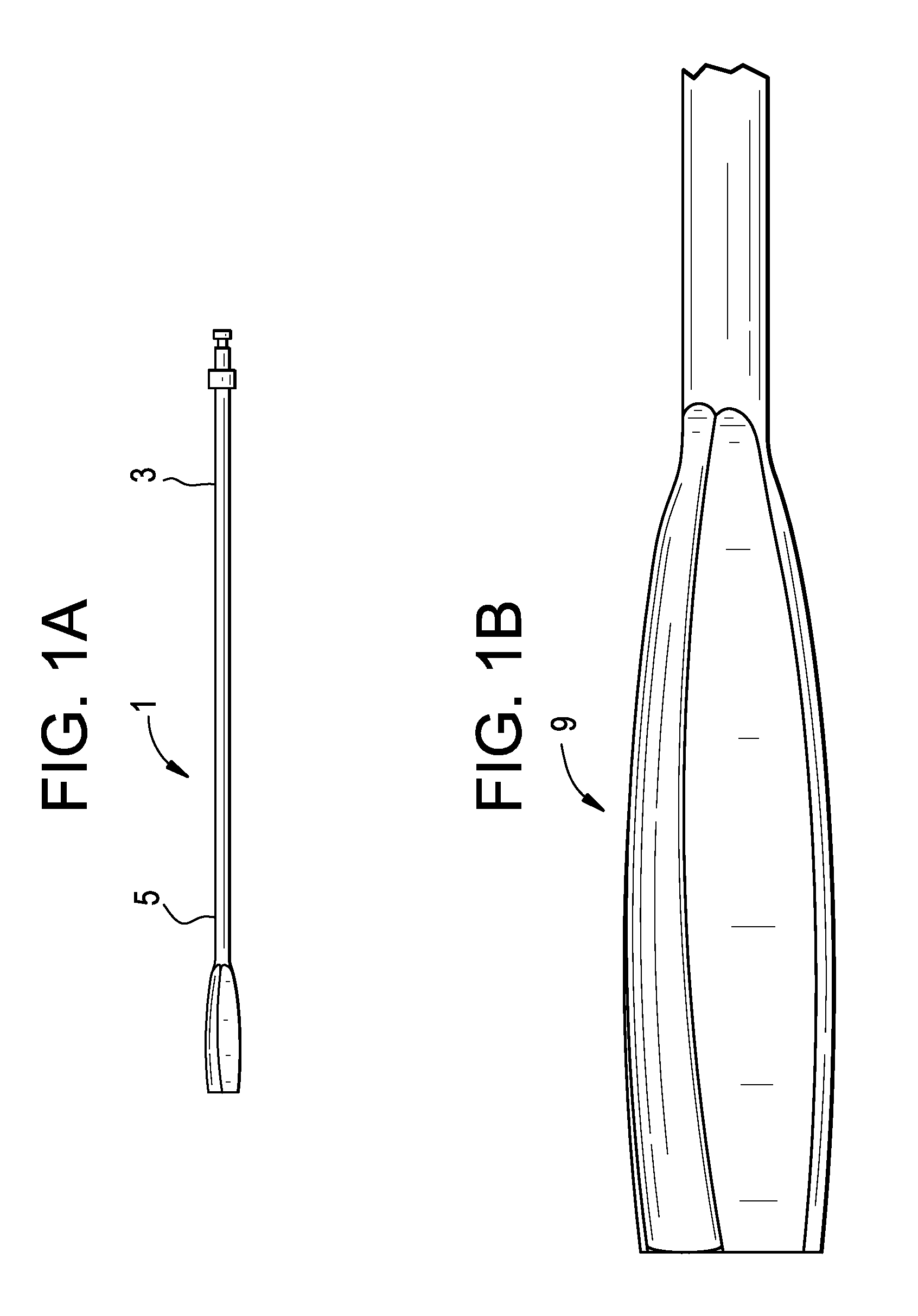
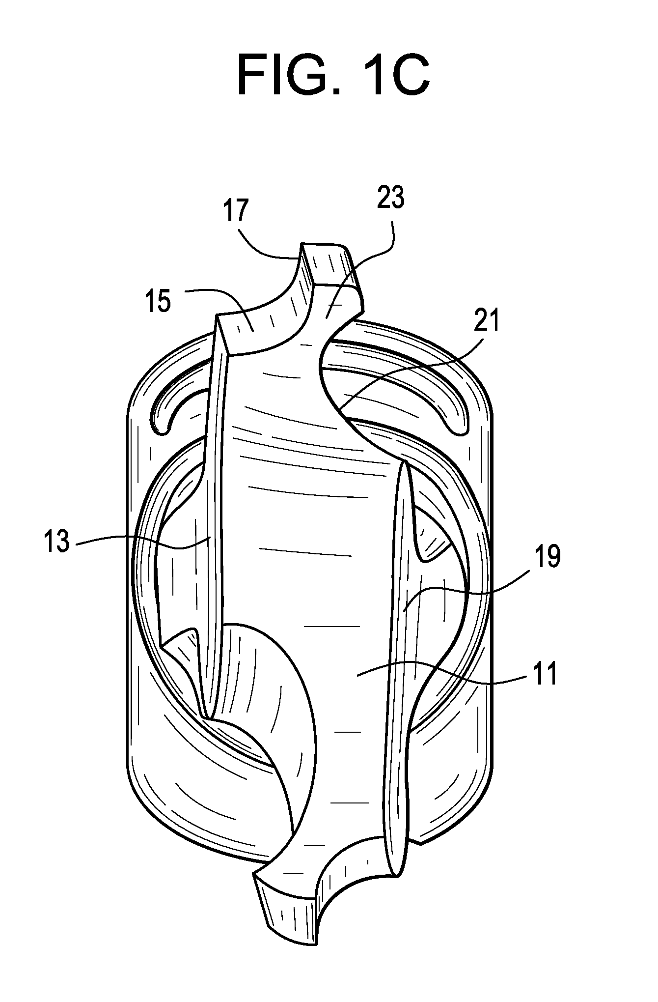
[0067] Now referring to FIGS. 1A-1C, there is provided a flexible shaver for preparing a vertebral endplate, comprising: [0068] a) a shaft 1 having a proximal end portion 3 and a distal end portion 5, [0069] b) a handle (not shown) attached to the proximal end portion of the shaft, and [0070] c) a shaving head 9 attached to the distal end portion of the shaft, the head comprising: [0071] i) a (typically inflexible) body portion 11; [0072] ii) a first face 13 having a first recess 15 forming a first cutting edge 17 and [0073] iii) a second opposing face 19 having a second recess 21 forming a relief groove, [0074] wherein the first and second recesses form a flexible cutting edge portion 23 therebetween comprising the cutting edge.
[0075] The solid flexible shaver of FIGS. 1A-1C acts in a manner similar to a conventional rigid endplate shaver, except that it is designed to deflect upon excessive torque load, thereby preventing excessive endplate damage. Preferably, a non-rigid material is utilized as the material of construction for this shaver, including polyethersulfone, polyphenylsulfone, polyurethane, polyamides, polyimides, PEEK, polyethylene, polypropylene, and superelastic materials. In another embodiment, a spring steel is used to provide the flexing. The selected material and geometry of the shaver are such that the shaving head experiences only elastic deformations and easily recovers following loading. In some embodiments, features may be added to the solid flexible shaver to enable bending at specific locations to prevent endplate damage at known torsion loads and/or at a specific disc space height(s).
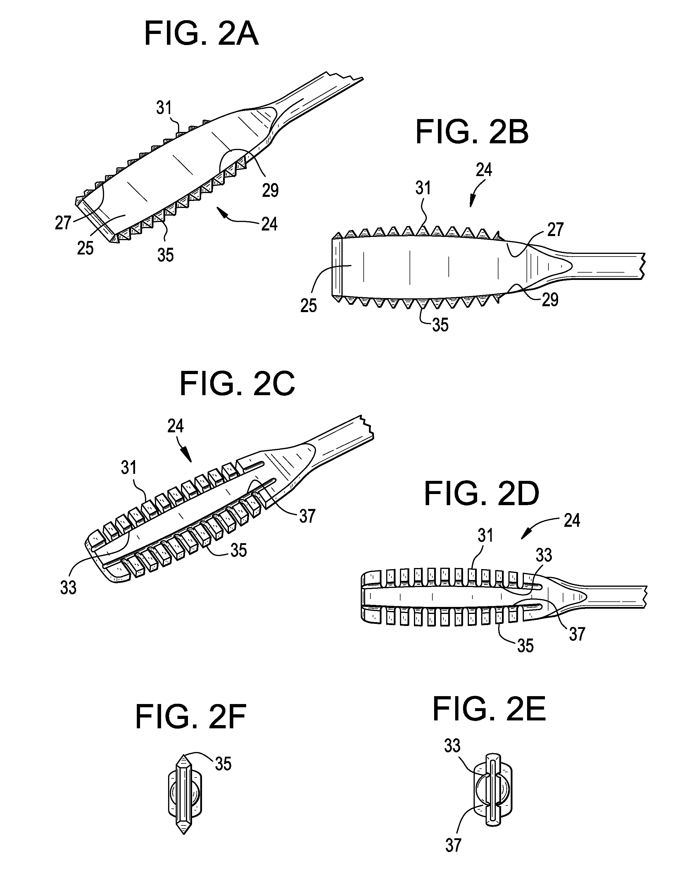
[0076] Now referring to FIGS. 2A-2F, there is provided a flexible shaver for preparing a vertebral endplate, comprising: [0077] a) a shaft having a proximal end portion and a distal end portion, [0078] b) a handle (not shown) attached to the proximal end portion of the shaft, and [0079] c) a shaving head 24 attached to the distal end portion of the shaft, the head comprising: [0080] i) a (typically inflexible) body portion 25 having an upper face 27 and a lower face 29; ii) a first row of teeth 31, each tooth extending from the upper face from a first respective junction 33; [0081] iii) a second row of teeth 35, each tooth extending from the lower face from a second respective junction 37; wherein each tooth has a thickness and each respective junction has a thickness, and wherein the thickness of at least one tooth is greater than the thickness of its respective junction.
[0082] In the FIGS. 2A-2F, solid shavers are disclosed with flexible teeth that independently elastically deform, thereby enabling preparation of the variable surface of the endplate while minimizing endplate damage. The size and shape of the teeth can be modified to control stiffness and relief. Bend grooves at junctions 33 and 37 ensure teeth flexibility at a known location and/or a known load.
[0083] Now referring to FIGS. 3A-3D, there is provided a flexible shaver for preparing a vertebral endplate, comprising: [0084] a) a shaft having a proximal end portion and a distal end portion, [0085] b) a handle attached to the proximal end portion of the shaft, and [0086] c) a shaving head 40 attached to the distal end portion of the shaft, the head comprising: [0087] i) a body portion 41 having an upper portion 43, a lower portion 45, a proximal portion 46 and a distal portion 48, the body portion having a first window 47 extending between the proximal and distal portions; [0088] ii) a first row of teeth 49 extending from the upper portion; [0089] iii) a second row of teeth 51 extending from the lower portion, wherein the first window imparts flexibility to the body portion.
[0090] The open flexible shaver of FIGS. 3A-3D, incorporates one or more open areas or internal windows in the shaving head. Upon exposure of a beam to a critical load, the window provides leaf spring-type elastic deformation of the shaver beam (such beams being formed as the upper, lower, proximal and distal portions around the window) that flex inward. A relatively non-rigid material of construction may be utilized including polyethersulfone, polyphenylsulfone, polyurethane, polyamides, polyimides, PEEK, polyethylene, polypropylene, and superelastic materials. In other embodiments, spring steel is used. The windows also provide a means for disc tissue removal as tissue is collected in the windows following shaving.
[0091] Now referring to FIGS. 4A-4B, there is provided a flexible shaver for preparing a vertebral endplate, comprising: [0092] a) a shaft having a proximal end portion and a distal end portion, [0093] b) a handle attached to the proximal end portion of the shaft, and [0094] c) a shaving head 60 attached to the distal end portion of the shaft, the head comprising: [0095] i) a body portion 61 having an upper portion 63, a lower portion 65, a proximal portion 66 and a distal portion 67, the flexible body portion having a first window 69 extending between the proximal and distal portions; the window forming upper 71 and lower 73 inner surfaces, [0096] ii) a first cutting surface 75 extending from the upper portion; [0097] iii) a second cutting surface 77 extending from the lower portion, wherein the upper inner surface has a proximal 81 and a distal 82 groove therein, wherein the lower inner surface has a proximal 83 and a distal 84 groove therein, wherein each groove imparts flexibility into the shaving head.
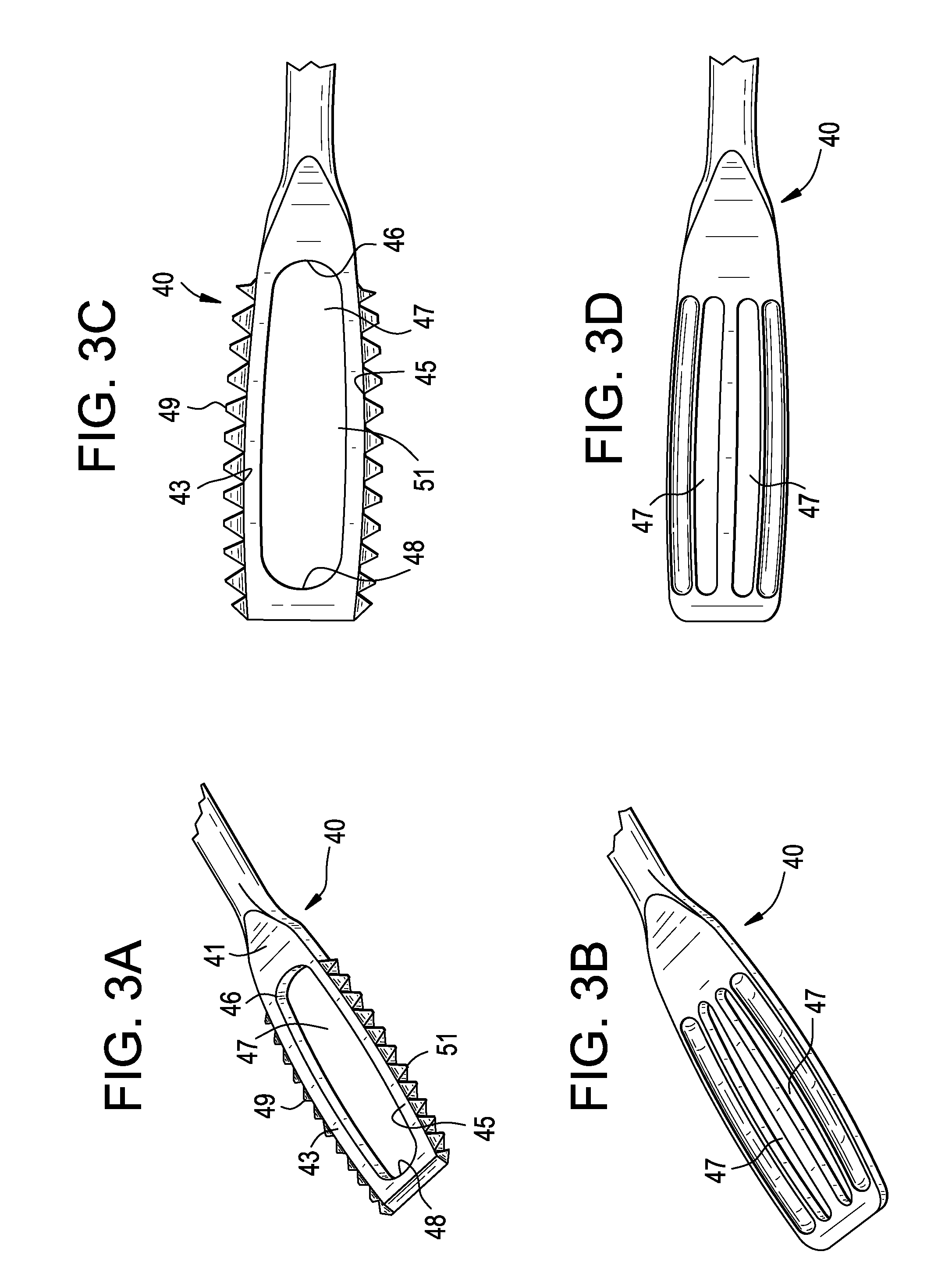
[0098] The open shaver of FIGS. 4A-4B incorporates a plurality of flexion grooves that provide elastic deformation at known loads and/or locations. For example, the grooves can be spaced/sized in order to provide variable flexibility at specific locations.
[0099] In other embodiments, the inner surfaces have more than two grooves. As shown in FIG. 4B, the distal end of the shaver can have a bulleted nose 70.
[0100] Now referring to FIGS. 5A-5B, there is provided a flexible shaver for preparing a vertebral endplate, comprising: [0101] a) a shaft 1 having a proximal end portion 3 and a distal end portion 5, [0102] b) a handle (not shown) attached to the proximal end portion of the shaft, and [0103] c) a shaving head 80 attached to the distal end portion of the shaft, the head comprising: [0104] i) a body portion 85 having an upper face 86, a lower face 87, and a distal face 89, the body portion having a deep recess 93 in the distal face extending proximally to form upper 95 and lower 97 extensions, [0105] ii) a first cutting surface 99 extending from the upper face; [0106] iii) a second cutting surface 100 extending from the lower face, wherein the deep recess imparts flexibility to the extensions.
[0107] The open shaver of FIGS. 5A-5B can be "forked" to control the amount of deflection and associated endplate preparation force applied to contra-lateral, anterior, or posterior aspects of the disc space. The extensions of the fork can be parallel, diverging or converging.
[0108] Now referring to FIGS. 6A-6B, there is provided a flexible shaver for preparing a vertebral endplate, comprising: [0109] a) a shaft 1 having a proximal end portion 3 and a distal end portion 5, [0110] b) a handle attached to the proximal end portion of the shaft, and [0111] c) a shaving head 9 attached to the distal end portion of the shaft, the head comprising: [0112] i) a body portion 101 having an upper face 103 and a lower face 105, [0113] ii) a first cutting element 107 spring-biased against the upper face, [0114] iii) a second cutting element 109 spring-biased against the lower face.
[0115] This spring shaver incorporates one or more inner compression springs 111 including a coil, a belleville washer, a leaf spring, and an elastic bumper. These springs support the floating cutting blades of the shaver. When the springs experience an excessive load, the springs compress and cause the shaver blades to retract, thereby reducing the amount of endplate damage. The shaver blade and associated springs can be segregated to control amount of deflection and associated endplate preparation force applied to contra-lateral, anterior, or posterior aspects of the disc space. Either the shaver blade geometry or the amount of spring force incorporated for the segregated blades can be modified to provide lordosis during endplate preparation.
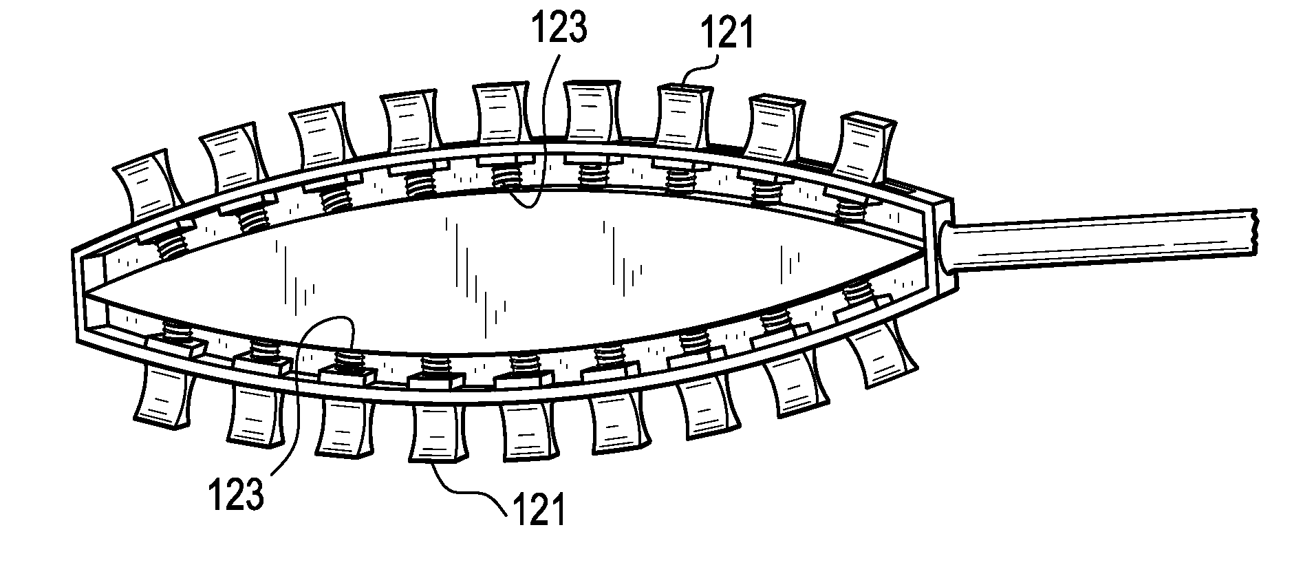
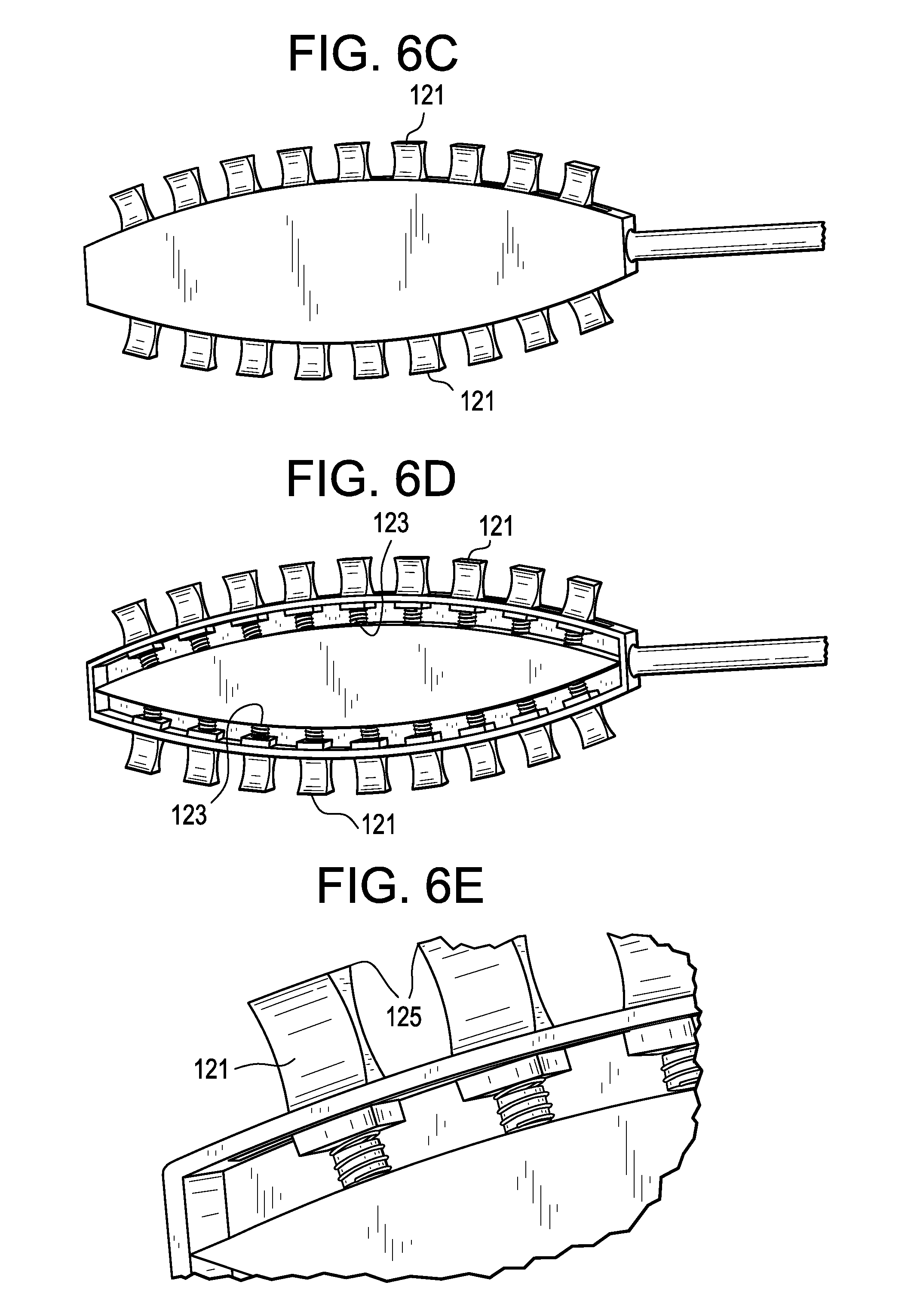
[0116] Now referring to FIGS. 6C-6E, there is provided an embodiment having individually spring-loaded teeth. The teeth 121 are arranged in a curved contour to better adhere to anatomical configurations. There can be a different number of teeth based on user preference or optimization activities. These teeth recess into the body of the shaver in response to shaver-bone contact and they are pushed back out to their initial position by axial springs 123 when the contact is removed. The teeth have cutting surfaces 125 that are designed to shave intrer-discal tissue when the instrument is being rotated in the clockwise or counterclockwise direction. However, the teeth could be designed for unidirectional cutting if desired. The advantage of this design is such that if and when the individual cutting teeth accidentally hit bone formations or contours, they are able to recess without damaging the bone but are still able to cut and remove soft tissue. The extent to which these teeth are able to move in and out of the shaver head can be tuned in through spring selection. It is believed that this embodiment may provide a more anatomically-responsive shaver in any part of the disc space through its shape adaptations. Overall, this instrument will help prevent endplate damage and will allow for proper cage placement without the incidence of gross subsidence.
[0117] In using the shaver, the surgeon will typically precut the disc annulus to create an entry window. The surgeon then inserts the distal end of the shaver into the disc space. The top and bottom faces are preferably parallel to the endplates upon insertion. The surgeon then rotates the shaver to rotate the cutting edges against the vertebral endplates. As the shaver with cutting edges is rotated, the disc nucleus pulposus, annulus, and cartilaginous tissue are cut or excised from the vertebral endplates. The shaver flexibility allows for deflection at locations where excessive loads are being incurred, thereby preventing excessive endplate damage. The shaver can be advanced further into the disc such that the contra-lateral aspects of the disc including the annulus are cut and excised. Following use, the shaver is withdrawn from the disc and any tissue which has accumulated within the shaver windows is removed. Shavers from a kit of various sizes, geometries or flexibilities can be used to customize the disc clearing and control the amount of cartilaginous tissue from the endplate.
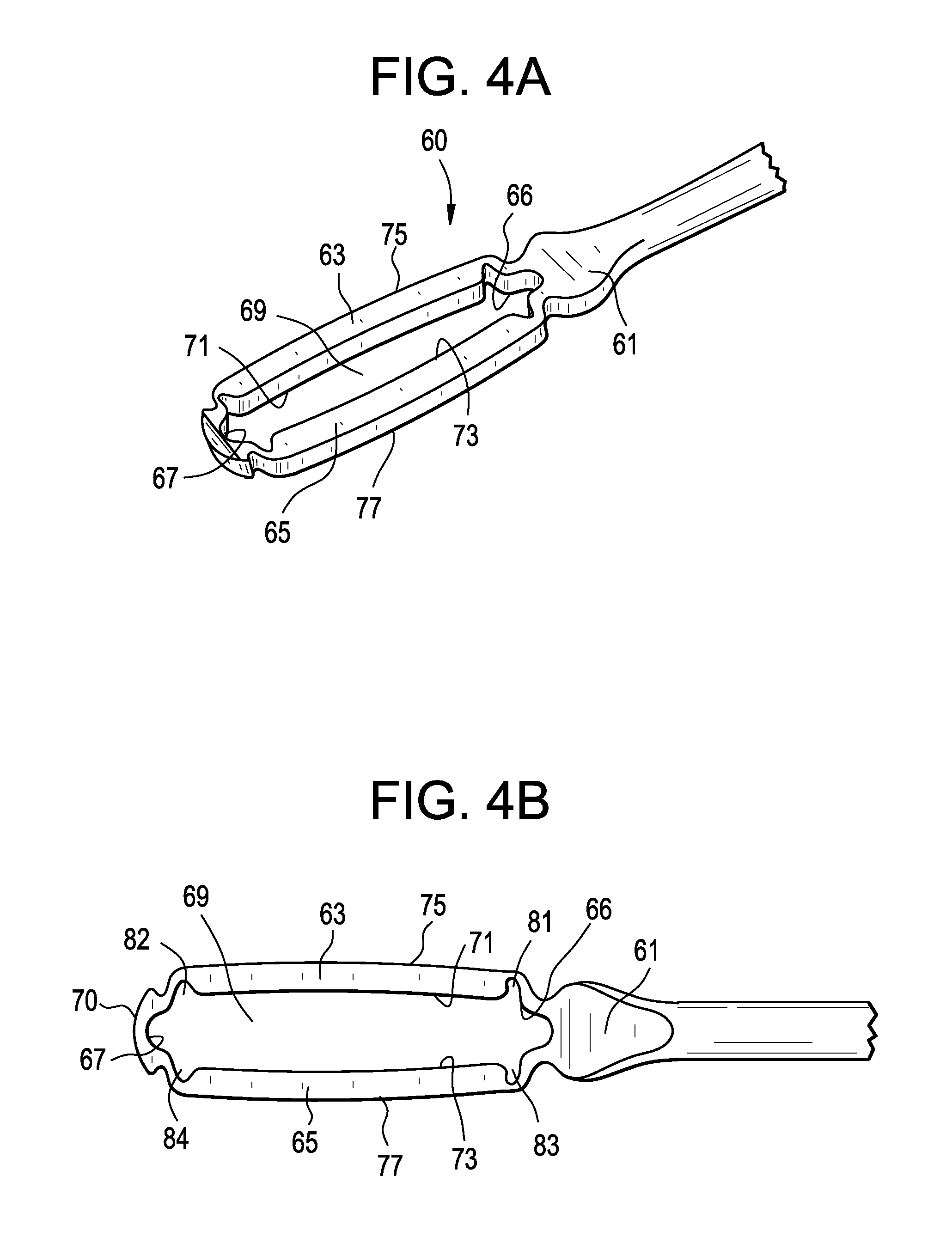
[0118] The surgeon can perform the surgery with the flexible shavers from the any access location of the disc including posterior, lateral, anterior-lateral or lateral.
[0119] In certain embodiments, these flexible shavers are used to prepare vertebral endplates associated with the L5/S1 functional spinal unit for the lateral insertion of a fusion cage.
[0120] Therefore, in accordance with the present invention, there is provided a method of preparing a vertebral endplate, comprising the steps of: [0121] a) removing an intervertebral disc to create a disc space and expose first and second vertebral endplates, [0122] b) inserting a shaver of the present invention into the disc space, and [0123] c) moving the shaver against at least one of the vertebral endplates to remove cartilage from the vertebral endplate.
[0124] In preferred embodiments, the method comprises the steps of: [0125] i) selecting an endplate shaver comprising: [0126] a. a shaft having a proximal end portion and a distal end portion, [0127] b. a handle attached to the proximal end portion of the shaft, and [0128] c. a shaving head attached to the distal end portion of the shaft, the head comprising a flexible portion, and [0129] ii) contacting the shaving head to the vertebral body endplate to shave the endplate.
[0130] When a flexible material is selected as the material of construction for a shaver of the present invention, the flexible material is preferably selected from the group consisting of polyethersulfone, polyphenylsulfone, polyurethane, polyamides, polyimides, PEEK, polyethylene, polypropylene, and superelastic materials. When a rigid material is selected as the material of construction for a shaver of the present invention, the rigid material is preferably a metal and is more preferably selected from the group consisting of stainless steel, chromium cobalt, and titanium alloy.
[0131] In some embodiments, there is provided a kit of a plurality of shavers of the present invention. The shavers in the kit may be of different sizes, or of different flexibilities, or both. Some kits of the present invention may include a plurality of identical shavers. Some kits may include a standard shaft-and-handle component to which may be attached a plurality of modular shaving heads.
* * * * *
D00000
D00001
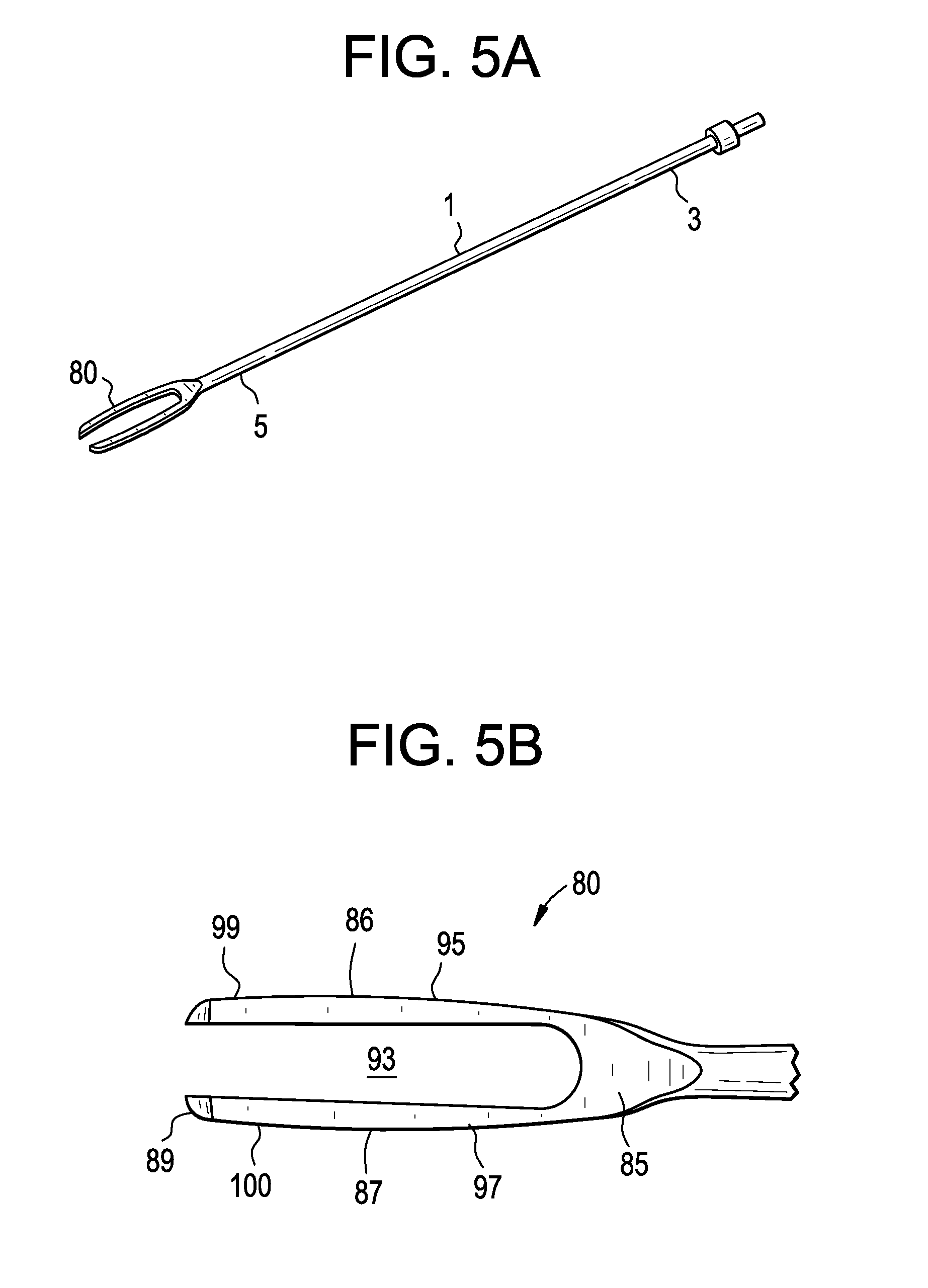
D00002
D00003
D00004
D00005
D00006
D00007
D00008
XML
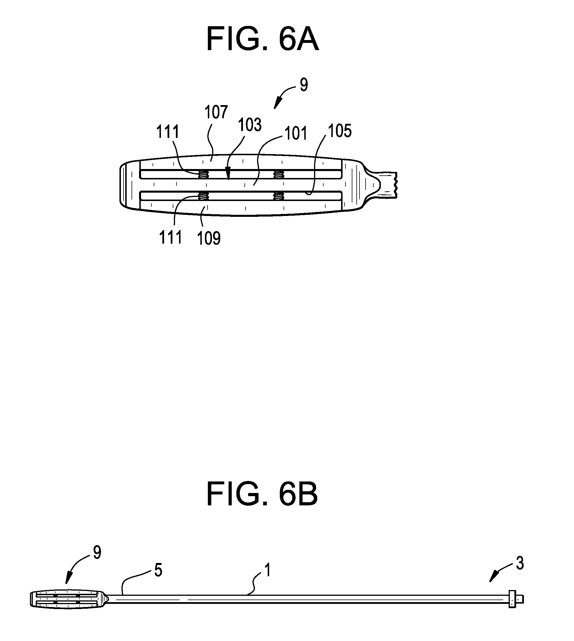
uspto.report is an independent third-party trademark research tool that is not affiliated, endorsed, or sponsored by the United States Patent and Trademark Office (USPTO) or any other governmental organization. The information provided by uspto.report is based on publicly available data at the time of writing and is intended for informational purposes only.
While we strive to provide accurate and up-to-date information, we do not guarantee the accuracy, completeness, reliability, or suitability of the information displayed on this site. The use of this site is at your own risk. Any reliance you place on such information is therefore strictly at your own risk.
All official trademark data, including owner information, should be verified by visiting the official USPTO website at www.uspto.gov. This site is not intended to replace professional legal advice and should not be used as a substitute for consulting with a legal professional who is knowledgeable about trademark law.