Intervertebral Implant Inserters And Related Methods
Dittmann; Dirk ; et al.
U.S. patent application number 16/103136 was filed with the patent office on 2019-02-14 for intervertebral implant inserters and related methods. The applicant listed for this patent is DePuy Synthes Products, Inc.. Invention is credited to Dirk Dittmann, William Miller, Jeff Walker.
| Application Number | 20190046334 16/103136 |
| Document ID | / |
| Family ID | 65274438 |
| Filed Date | 2019-02-14 |


| United States Patent Application | 20190046334 |
| Kind Code | A1 |
| Dittmann; Dirk ; et al. | February 14, 2019 |
INTERVERTEBRAL IMPLANT INSERTERS AND RELATED METHODS
Abstract
Implant inserters and related methods are disclosed herein, e.g., for delivering a fusion cage or other implant to a spinal disc space and for rotating or articulating the implant within the disc space. An exemplary instrument can include an inner member having opposed jaws for grasping the implant and holding the implant during insertion. The inner member can be slidably received within an outer member such that relative axial translation of the inner and outer members is effective to open or close the jaws. The jaws and/or the distal end of the outer member can have a low-profile geometry, which can advantageously facilitate certain surgical procedures. For example, the low-profile geometry can allow for a more medial approach to an intervertebral disc space in which the implant is to be inserted.
| Inventors: | Dittmann; Dirk; (Basel, CH) ; Miller; William; (Middleboro, MA) ; Walker; Jeff; (Barrington, RI) | ||||||||||
| Applicant: |
|
||||||||||
|---|---|---|---|---|---|---|---|---|---|---|---|
| Family ID: | 65274438 | ||||||||||
| Appl. No.: | 16/103136 | ||||||||||
| Filed: | August 14, 2018 |
Related U.S. Patent Documents
| Application Number | Filing Date | Patent Number | ||
|---|---|---|---|---|
| 62544997 | Aug 14, 2017 | |||
| Current U.S. Class: | 1/1 |
| Current CPC Class: | A61F 2002/4627 20130101; A61F 2/4611 20130101; A61F 2002/4629 20130101; A61F 2/442 20130101; A61F 2/4455 20130101 |
| International Class: | A61F 2/46 20060101 A61F002/46; A61F 2/44 20060101 A61F002/44 |
Claims
1. A surgical instrument, comprising: an outer member having a central longitudinal axis; an inner member having a medial jaw and a lateral jaw, the inner member being axially translatable within an inner passage of the outer member to move the jaws towards one another to a closed position, thereby grasping an implant; wherein at least one of the following conditions is true when the jaws are in the closed position: the medial jaw has a length that is less than a length of the lateral jaw; the medial jaw has a knuckle width that is less than a knuckle width of the lateral jaw; the medial jaw is asymmetrical to the lateral jaw; a claw opening distance between the medial and lateral jaws is oriented at an oblique angle with respect to the central longitudinal axis of the outer member; the distal end of the outer member has a width that is less than a maximum outer width of the medial and lateral jaws; the distance between the maximum lateral extent of the lateral jaw and the central longitudinal axis of the outer member is greater than the distance between the maximum medial extent of the medial jaw and the central longitudinal axis of the outer member; a maximum medial extent of the medial jaw is less than or equal to a maximum medial extent of the outer member; and a maximum medial extent of the medial jaw is less than or equal to a maximum medial extent of an implant loaded into the instrument.
2. A surgical instrument, comprising: an outer member having a central longitudinal axis; and an inner member having a medial jaw and a lateral jaw, the inner member being axially translatable within an inner passage of the outer member to move the jaws towards one another to a closed position, thereby grasping an implant.
3. The instrument of claim 2, wherein the medial jaw has a length that is less than a length of the lateral jaw when the jaws are in the closed position.
4. The instrument of claim 2, wherein the medial jaw has a knuckle width that is less than a knuckle width of the lateral jaw.
5. The instrument of claim 2, wherein the medial jaw is asymmetrical to the lateral jaw.
6. The instrument of claim 2, wherein a claw opening distance between the medial and lateral jaws is oriented at an oblique angle with respect to the central longitudinal axis of the outer member.
7. The instrument of claim 2, wherein the distal end of the outer member has a width that is less than a maximum outer width of the medial and lateral jaws when the jaws are in the closed position.
8. The instrument of claim 2, wherein the distance between the maximum lateral extent of the lateral jaw and the central longitudinal axis of the outer member is greater than the distance between the maximum medial extent of the medial jaw and the central longitudinal axis of the outer member when the jaws are in the closed position.
9. The instrument of claim 2, wherein a maximum medial extent of the medial jaw is less than or equal to a maximum medial extent of the outer member when the jaws are in the closed position.
10. The instrument of claim 2, wherein a maximum medial extent of the medial jaw is less than or equal to a maximum medial extent of an implant loaded into the instrument when the jaws are in the closed position.
11. The instrument of claim 2, further comprising an implant grasped between the medial and lateral jaws of the inner member; wherein the medial jaw does not protrude or overhang the implant in the medial direction.
12. A surgical method, comprising: coupling an implant to an inserter such that the inserter does not protrude or overhang the implant on at least a first side thereof; passing the implant into a disc space between two vertebrae such that the first side faces in the medial direction; and releasing the implant from the inserter.
13. The method of claim 12, wherein coupling the implant to the inserter includes passing a portion of the implant into an opening between two jaws of the inserter and moving the two jaws toward one another to clamp the implant.
14. The method of claim 13, wherein moving the two jaws toward one another includes distally advancing an outer member relative to an inner member on which the two jaws are formed.
15. The method of claim 14, wherein releasing the implant from the inserter includes proximally withdrawing the outer member relative to the inner member.
16. The method of claim 12, wherein passing the implant into the disc space is done using any of a PLIF approach, a TLIF approach, a medially-shifted PLIF approach, and a medially-shifted TLIF approach.
Description
CROSS-REFERENCE TO RELATED APPLICATIONS
[0001] This application claims the benefit of U.S. Provisional Application No. 62/544,997, filed Aug. 14, 2017, the entire contents of which are incorporated herein by reference.
FIELD
[0002] Implant inserters and related methods are disclosed herein, e.g., for delivering a fusion cage or other implant to a spinal disc space and for rotating or articulating the implant within the disc space.
BACKGROUND
[0003] There are a number of surgical procedures in which an implant is delivered to a location within a patient. In spine surgery, for example, a fusion cage, disc prosthesis, or other implant may be delivered to a disc space defined between two vertebrae. Insertion and proper positioning of the implant can be challenging for the surgeon, particularly when the implant is delivered through a narrow working channel, e.g., in the case of minimally-invasive approaches to the spine.
[0004] By way of further example, in some spinal surgeries, a relatively medial posterior approach to an intervertebral disc space can be desired because the degree of muscle stripping and soft tissue retraction required to access the disc space can be reduced relative to other approaches. In such cases, however, any instruments passed to the surgical site can come close to the spinal cord. With prior devices, such an approach can be impractical or impossible due to the device being too large to pass into the disc space without undesirably contacting sensitive anatomic structures like the spinal cord.
[0005] Accordingly, there is a need for improved instruments having reduced profile geometries to allow insertion through narrow passages or working channels. In particular, there is a need for improved implant inserters and related methods that can facilitate insertion and proper positioning of an implant within a patient.
SUMMARY
[0006] Implant inserters and related methods are disclosed herein, e.g., for delivering a fusion cage or other implant to a spinal disc space and for rotating or articulating the implant within the disc space. An exemplary instrument can include an inner member having opposed jaws for grasping the implant and holding the implant during insertion. The inner member can be slidably received within an outer member such that relative axial translation of the inner and outer members is effective to open or close the jaws. The jaws and/or the distal end of the outer member can have a low-profile geometry, which can advantageously facilitate certain surgical procedures. For example, the low-profile geometry can allow for a more medial approach to an intervertebral disc space in which the implant is to be inserted.
[0007] In one aspect, a surgical instrument is provided that can include an outer member having a central longitudinal axis and an inner member having a medial jaw and a lateral jaw. Further, the inner member can be axially translatable within an inner passage of the outer member to move the jaws towards one another to a closed position, thereby grasping an implant. Still further, at least one of the following conditions can be true when the jaws are in the closed position: the medial jaw can have a length that is less than a length of the lateral jaw; the medial jaw can have a knuckle width that is less than a knuckle width of the lateral jaw; the medial jaw can be asymmetrical to the lateral jaw; a claw opening distance between the medial and lateral jaws can be oriented at an oblique angle with respect to the central longitudinal axis of the outer member; the distal end of the outer member can have a width that is less than a maximum outer width of the medial and lateral jaws; the distance between the maximum lateral extent of the lateral jaw and the central longitudinal axis of the outer member can be greater than the distance between the maximum medial extent of the medial jaw and the central longitudinal axis of the outer member; a maximum medial extent of the medial jaw can be less than or equal to a maximum medial extent of the outer member; and a maximum medial extent of the medial jaw can be less than or equal to a maximum medial extent of an implant loaded into the instrument.
[0008] In another aspect, a surgical instrument is provided that can include an outer member having a central longitudinal axis and an inner member having a medial jaw and a lateral jaw. Further, the inner member can be axially translatable within an inner passage of the outer member to move the jaws towards one another to a closed position, thereby grasping an implant.
[0009] The devices and methods described herein can have a number of additional features and/or variations, all of which are within the scope of the present disclosure. In some embodiments, for example, the medial jaw can have a length that is less than a length of the lateral jaw when the jaws are in the closed position.
[0010] In certain embodiments, the medial jaw can have a knuckle width that is less than a knuckle width of the lateral jaw. And in some embodiments, the medial jaw can be asymmetrical to the lateral jaw. Further, in some embodiments a claw opening distance between the medial and lateral jaws can be oriented at an oblique angle with respect to the central longitudinal axis of the outer member.
[0011] In some embodiments, the distal end of the outer member can have a width that is less than a maximum outer width of the medial and lateral jaws when the jaws are in the closed position. And in certain embodiments, the distance between the maximum lateral extent of the lateral jaw and the central longitudinal axis of the outer member can be greater than the distance between the maximum medial extent of the medial jaw and the central longitudinal axis of the outer member when the jaws are in the closed position.
[0012] In certain embodiments, a maximum medial extent of the medial jaw can be less than or equal to a maximum medial extent of the outer member when the jaws are in the closed position. While in some embodiments, a maximum medial extent of the medial jaw can be less than or equal to a maximum medial extent of an implant loaded into the instrument when the jaws are in the closed position.
[0013] In some embodiments, the instrument can further include an implant grasped between the medial and lateral jaws of the inner member, and the medial jaw does not protrude or overhang the implant in the medial direction.
[0014] In another aspect, a surgical method is provided that can include coupling an implant to an inserter such that the inserter does not protrude or overhang the implant on at least a first side thereof, passing the implant into a disc space between two vertebrae such that the first side faces in the medial direction, and releasing the implant from the inserter.
[0015] As with the above-described aspect, a number of additional features and/or variations can be included, all of which are within the scope of the present disclosure. In some embodiments, for example, coupling the implant to the inserter can include passing a portion of the implant into an opening between two jaws of the inserter and moving the two jaws toward one another to clamp the implant. And in certain embodiments, moving the two jaws toward one another can include distally advancing an outer member relative to an inner member on which the two jaws are formed. Further, in some embodiments releasing the implant from the inserter can include proximally withdrawing the outer member relative to the inner member.
[0016] The method can be used in a variety of procedures. For example, in certain embodiments passing the implant into the disc space can be done using any of a PLIF approach, a TLIF approach, a medially-shifted PLIF approach, and a medially-shifted TLIF approach.
[0017] Any of the features or variations described above can be applied to any particular aspect or embodiment of the present disclosure in a number of different combinations. The absence of explicit recitation of any particular combination is due solely to the avoidance of repetition in this summary.
BRIEF DESCRIPTION OF THE DRAWINGS
[0018] The aspects and embodiments described above will be more fully understood from the following detailed description taken in conjunction with the accompanying drawings, in which:
[0019] FIG. 1 is a transverse plane sectional view of a human spine, showing an instrument being used to insert an implant into an intervertebral disc space;
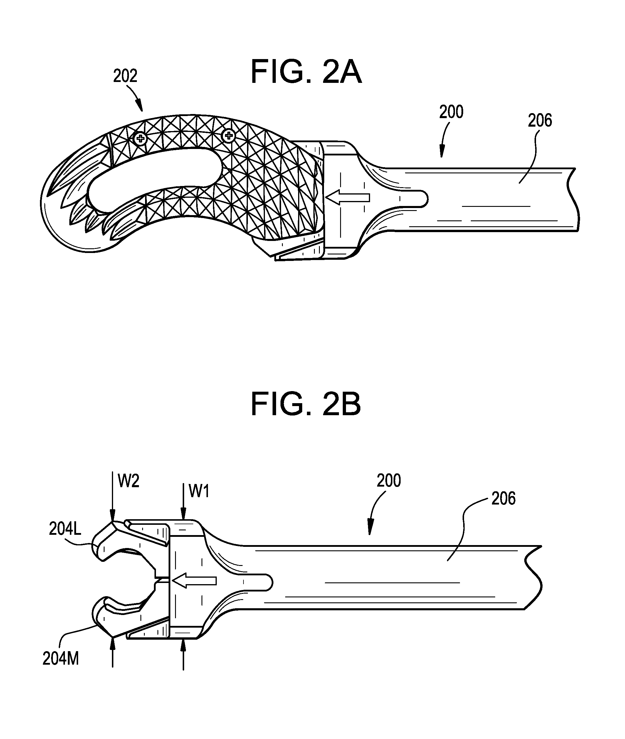
[0020] FIG. 2A is a top view of a predicate implant inserter, shown with an implant loaded into the inserter;
[0021] FIG. 2B is a top view of the predicate implant inserter of FIG. 2A, shown in an unloaded configuration;
[0022] FIG. 3A is a top view of an implant inserter in accordance with the present disclosure, shown with an implant loaded into the inserter;
[0023] FIG. 3B is a top view of the implant inserter of FIG. 3A, shown in an unloaded configuration;
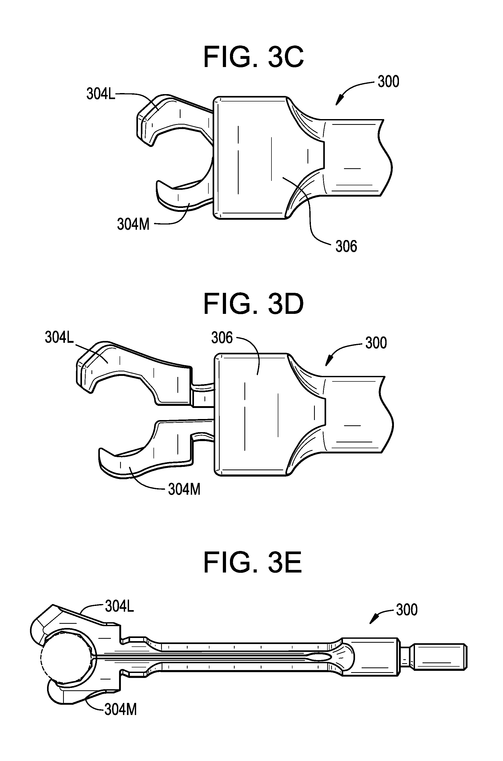
[0024] FIG. 3C is a top view of the implant inserter of FIG. 3A, shown in a closed position;
[0025] FIG. 3D is a top view of the implant inserter of FIG. 3A, shown in an open position;
[0026] FIG. 3E is a top view of an inner member of the implant inserter of FIG. 3A;
[0027] FIG. 3F is a detail top view of the implant inserter of FIG. 3A;
[0028] FIG. 4A is a top view of another implant inserter in accordance with the present disclosure, shown with an implant loaded into the inserter;
[0029] FIG. 4B is a top view of the implant inserter of FIG. 4A, shown in an unloaded configuration;
[0030] FIG. 5A is a top view of an implant inserter in accordance with the present disclosure, shown with an implant loaded into the inserter; and
[0031] FIG. 5B is a top view of the implant inserter of FIG. 5A, shown with a trial spacer loaded into the inserter.
DETAILED DESCRIPTION
[0032] Implant inserters and related methods are disclosed herein, e.g., for delivering a fusion cage or other implant to a spinal disc space and for rotating or articulating the implant within the disc space. An exemplary instrument can include an inner member having opposed jaws for grasping the implant and holding the implant during insertion. The inner member can be slidably received within an outer member such that relative axial translation of the inner and outer members is effective to open or close the jaws. The jaws and/or the distal end of the outer member can have a low-profile geometry, which can advantageously facilitate certain surgical procedures. For example, the low-profile geometry can allow for a more medial approach to an intervertebral disc space in which the implant is to be inserted.
[0033] Certain exemplary embodiments will now be described to provide an overall understanding of the principles of the structure, function, manufacture, and use of the instruments and methods disclosed herein. One or more examples of these embodiments are illustrated in the accompanying drawings. Those skilled in the art will understand that the instruments and methods specifically described herein and illustrated in the accompanying drawings are non-limiting exemplary embodiments. The features illustrated or described in connection with one exemplary embodiment may be combined with the features of other embodiments.
[0034] FIG. 1 illustrates an exemplary spinal surgical procedure in which an implant 100 is inserted into an intervertebral disc space 102. The implant 100 can be a fusion cage designed to promote fusion between vertebrae above and below the disc space 102. The fusion cage 100 and/or the disc space 102 surrounding the cage can be packed with bone graft material 104 or other fusion-promoting substances. In other embodiments, the implant 100 can be a disc prosthesis, motion preserving implant, or the like. The implant 100 can be delivered to the disc space 102 using an inserter instrument 106. The implant 100 can be delivered using any of a variety of approaches to the intervertebral disc space 102, with each approach having certain potential advantages and/or disadvantages. One advantage of a relatively medial posterior approach to the disc space 102 is that the degree of muscle stripping and soft tissue retraction required to access the disc space may be reduced as compared to more lateral approaches. As shown in FIG. 1, the degree to which an approach can be shifted in the medial direction is limited by the location of the spinal cord 108 and/or other delicate anatomical structures. When a relatively medial posterior approach is used to access the disc space 102, the inserter instrument 106 must pass very close to the spinal cord 108. By reducing the profile of the inserter instrument 106, and in particular the medial aspects of the inserter instrument, the implant 100 can be inserted along a path that is more medial and thus potentially less invasive.
[0035] FIGS. 2A and 2B illustrate a predicate inserter instrument 200 shown with an implant 202 loaded into the inserter (FIG. 2A) and unloaded (FIG. 2B). Further details on the inserter instrument 200 and the implant 202 can be found in U.S. Publication No. 2011/0106259 entitled "SELF-PIVOTING SPINAL IMPLANT AND ASSOCIATED INSTRUMENTATION," which is hereby incorporated by reference herein. The inserter instrument 200 has an inner member with opposed medial and lateral jaws 204M, 204L for grasping the implant 202. The inner member is slidably received within an outer member 206 such that relative axial translation of the inner and outer members is effective to open or close the jaws 204. As shown, the jaws 204 are symmetrical to one another, i.e., such that each jaw has a shape that is the same but opposite that of the other jaw. In addition, the distal end of the outer member 206 has a width W1 that is relatively wide, the width W1 being equal to or greater than the maximum outer width W2 of the jaws 204. In use, the inserter instrument 200 is guided towards the disc space with the width dimensions W1, W2 oriented along the transverse plane. The geometry of the jaws 204 and/or of the distal end of the outer member 206 can limit the degree to which an approach to the disc space can be shifted medially.
[0036] FIGS. 3A-3F illustrate an inserter instrument 300 in accordance with the present disclosure. The instrument 300 is shown in FIGS. 3A and 3B with an implant 302 loaded into the inserter (FIG. 3A) and unloaded (FIG. 3B). The instrument 300 is shown in FIGS. 3C and 3D in a closed position (FIG. 3C) and an open position (FIG. 3D). FIGS. 3E and 3F show detailed views of the instrument 300. As shown, the inserter instrument 300 can have a reduced geometry as compared to the inserter instrument 200 of FIG. 2.
[0037] The medial jaw 304M of the instrument 300 can have a length LM that is shorter than the length LL of the lateral jaw 304L. The lengths LM, LL can be measured as the degree to which the jaws 304M, 304L protrude from the outer member 306 when the instrument 300 is in the closed position. The ratio LM:LL can be about 5:7 in the closed position. The ratio LM:LL can be in the range of about 0.5:1 to about 0.9:1 in the closed position. The medial jaw 304M can be shorter than the medial jaw 204M of FIG. 2, and the lateral jaw 304L can be longer than the lateral jaw 204L of FIG. 2.
[0038] The outer knuckle of the medial jaw 304M can be removed or reduced, such that the medial jaw has a knuckle width KWM that is less than the knuckle width KWL of the lateral jaw 304L. The outer knuckle of the lateral jaw 304L can be removed or reduced instead or in addition. The knuckle widths KWM, KWL can be equal. The ratio KWM:KWL can be about 0.86:1. The ratio KWM:KWL can be in the range of about 0.8:1 to about 0.9:1.
[0039] The medial jaw 304M can be asymmetrical to the lateral jaw 304L. The claw opening distance CO when the instrument is in the closed position can be the same or substantially the same as in the instrument 200 of FIG. 2. By maintaining the claw opening distance, claw grip strength can be optimized, e.g., for implant repositioning. The claw opening can be oriented at an oblique angle with respect to the central longitudinal axis A1 of the outer member 306.
[0040] The distal end of the outer member 306 can have a width W3 that is less than the width W1 of the outer member 206 of FIG. 2. The width W3 can be less than the maximum outer width W4 of the jaws 304M, 304L when the instrument is in the closed position. The width W3 can be slightly larger than the maximum outer width W4 of the jaws 304M, 304L when the instrument is in the closed position. The jaws 304M, 304L can be off-center from the outer member 306 when the instrument is in the closed position. The distance between the maximum lateral extent of the lateral jaw 304L and the central longitudinal axis A1 of the outer member 306 can be greater than the distance between the maximum medial extent of the medial jaw 304M and the axis A1 when the instrument is in the closed position.
[0041] The maximum lateral extent of the lateral jaw 304L can be lateral to the maximum lateral extent of the outer member 306 when the instrument is in the closed position. In other words, the lateral jaw 304L can protrude laterally from the outer member 306 when the instrument is in the closed position. The maximum medial extent of the medial jaw 304M can be lateral to the maximum medial extent of the outer member 306 when the instrument is in the closed position. The maximum medial extent of the medial jaw 304M can be flush with or equal to the maximum medial extent of the outer member 306 when the instrument is in the closed position. In other words, the medial jaw 304M can be configured such that it does not protrude medially from the outer member 306 when the instrument is in the closed position and/or such that it is recessed from the outer member 306 in the medial direction. The maximum medial extent of the medial jaw 304M can be less than the maximum medial extent of the implant 302 when the implant is loaded into the instrument as shown in FIG. 3A. The maximum medial extent of the outer member 306 can be less than the maximum medial extent of the implant 302 when the implant is loaded into the instrument as shown in FIG. 3A. As also shown in FIG. 3A, the medial jaw 304M can overhang the implant 302 by a medial overhang distance OM. The distance OM can be less than the corresponding distance in the inserter 200 of FIG. 2. In some embodiments, the distance OM can be zero or negative, e.g., such that the medial jaw 304M does not protrude or overhang the implant in the medial direction.
[0042] The above-described geometry, including the reduced dimension of the medial jaw 304M and/or of the distal end of the outer member 306, can advantageously allow the instrument 300 to be shifted more in the medial direction, allowing a more medial approach to the disc space and reducing the invasiveness of the procedure. The geometry of the jaws 304 can also facilitate release of the implant 302 from the instrument 300 when desired, particularly in the case of more medial approaches. For example, as noted above, the claw opening CO can be oriented at an oblique angle with respect to a central longitudinal axis of the outer member 306.
[0043] Except as described herein and as will be readily appreciated by a person having ordinary skill in the art in view of the present disclosure, the structure and operation of the inserter instrument 300 can be the same as that of the instruments described in U.S. Publication No. 2011/0106259 entitled "SELF-PIVOTING SPINAL IMPLANT AND ASSOCIATED INSTRUMENTATION." The instrument 300 can include any of the features described in the above reference.
[0044] FIGS. 4A and 4B illustrate top views of another inserter instrument 400 in accordance with the present disclosure, shown with an implant 402 loaded into the inserter (FIG. 4A) and unloaded (FIG. 4B). As shown, the distal end of the outer member 406 can have a gradual, atraumatic taper with smoothly curved transitions between each outer face of the outer member, thereby reducing the risk of tissue damage as the inserter instrument 400 is passed through patient anatomy.
[0045] As shown in FIGS. 5A and 5B, the inserter instruments disclosed herein can be used to deliver various implants or objects to a surgical site, such as a fusion cage (FIG. 5A) or a trial spacer (FIG. 5B).
[0046] In use, the instrument can be cleaned and/or sterilized to prepare the instrument for surgery. A fusion cage or other implant can be loaded onto the instrument and clamped by the jaws, as shown in FIG. 3A. The instrument can then be used to deliver the implant to a target site within a patient, for example by passing the implant into a spinal disc space through a minimally-invasive working channel or an open approach. The instrument can be inserted using a PLIF approach, a TLIF approach, a medially-shifted PLIF approach, a medially-shifted TLIF approach, and so forth. Once the implant is disposed within the disc space, or at any other time desired by the user, the instrument can be disconnected from the implant and the surgical procedure can be completed using known techniques.
[0047] It should be noted that any ordering of method steps expressed or implied in the description above or in the accompanying drawings is not to be construed as limiting the disclosed methods to performing the steps in that order. Rather, the various steps of each of the methods disclosed herein can be performed in any of a variety of sequences. In addition, as the described methods are merely exemplary embodiments, various other methods that include additional steps or include fewer steps are also within the scope of the present disclosure.
[0048] The instruments disclosed herein can be constructed from any of a variety of known materials. Exemplary materials include those which are suitable for use in surgical applications, including metals such as stainless steel, titanium, nickel, cobalt-chromium, or alloys and combinations thereof, polymers such as PEEK, ceramics, carbon fiber, and so forth. The various components of the instruments disclosed herein can be rigid or flexible. Device sizes can also vary greatly, depending on the intended use and surgical site anatomy. Furthermore, particular components can be formed from a different material than other components. One or more components or portions of the instruments can be formed from a radiopaque material to facilitate visualization under fluoroscopy and other imaging techniques, or from a radiolucent material so as not to interfere with visualization of other structures. Exemplary radiolucent materials include carbon fiber and high-strength polymers.
[0049] The instruments and methods disclosed herein can be used in minimally-invasive surgery and/or open surgery. While the instruments and methods disclosed herein are generally described in the context of spinal surgery on a human patient, it will be appreciated that the methods and instruments disclosed herein can be used in any type of surgery on a human or animal subject, in non-surgical applications, on non-living objects, and so forth.
[0050] The devices disclosed herein can be designed to be disposed after a single use, or they can be designed for multiple uses. In either case, however, the device can be reconditioned for reuse after at least one use. Reconditioning can include any combination of the steps of disassembly of the device, followed by cleaning or replacement of particular pieces, and subsequent reassembly. In particular, the device can be disassembled, and any number of the particular pieces or parts of the device can be selectively replaced or removed in any combination. Upon cleaning and/or replacement of particular parts, the device can be reassembled for subsequent use either at a reconditioning facility or by a surgical team immediately prior to a surgical procedure. Those skilled in the art will appreciate that reconditioning of a device can utilize a variety of techniques for disassembly, cleaning/replacement, and reassembly. Use of such techniques, and the resulting reconditioned device, are all within the scope of the present invention.
[0051] The devices described herein can be processed before use in a surgical procedure. First, a new or used instrument can be obtained and, if necessary, cleaned. The instrument can then be sterilized. In one sterilization technique, the instrument can be placed in a closed and sealed container, such as a plastic or TYVEK bag. The container and its contents can then be placed in a field of radiation that can penetrate the container, such as gamma radiation, x-rays, or high-energy electrons. The radiation can kill bacteria on the instrument and in the container. The sterilized instrument can then be stored in the sterile container. The sealed container can keep the instrument sterile until it is opened in the medical facility. Other forms of sterilization known in the art are also possible. This can include beta or other forms of radiation, ethylene oxide, steam, or a liquid bath (e.g., cold soak). Certain forms of sterilization may be better suited to use with different portions of the device due to the materials utilized, the presence of electrical components, etc.
[0052] All papers and publications cited herein are hereby incorporated by reference in their entirety. Although specific embodiments are described above, it should be understood that numerous changes may be made within the spirit and scope of the concepts described. Accordingly, the disclosure is not to be limited by what has been particularly shown and described, except as indicated by the appended claims.
* * * * *
D00000
D00001
D00002
D00003
D00004
D00005
D00006
D00007
XML
uspto.report is an independent third-party trademark research tool that is not affiliated, endorsed, or sponsored by the United States Patent and Trademark Office (USPTO) or any other governmental organization. The information provided by uspto.report is based on publicly available data at the time of writing and is intended for informational purposes only.
While we strive to provide accurate and up-to-date information, we do not guarantee the accuracy, completeness, reliability, or suitability of the information displayed on this site. The use of this site is at your own risk. Any reliance you place on such information is therefore strictly at your own risk.
All official trademark data, including owner information, should be verified by visiting the official USPTO website at www.uspto.gov. This site is not intended to replace professional legal advice and should not be used as a substitute for consulting with a legal professional who is knowledgeable about trademark law.