Connector having a grounding member
Krenceski , et al. March 30, 2
U.S. patent number 10,965,063 [Application Number 16/653,713] was granted by the patent office on 2021-03-30 for connector having a grounding member. This patent grant is currently assigned to PPC BROADBAND, INC.. The grantee listed for this patent is PPC BROADBAND, INC.. Invention is credited to Mary Krenceski, Roger Mathews, Noah P. Montena.


| United States Patent | 10,965,063 |
| Krenceski , et al. | March 30, 2021 |
Connector having a grounding member
Abstract
A grounding member for maintaining a ground path in a cable connector includes, in one embodiment, an inner core configured to flex when a force is applied to the grounding member during operation of the connector. The grounding member further includes an outer conductive coating applied to the inner core. The outer conductive coating is configured to flex from a first state to a second state when a force is applied to the grounding member, so as to maintain a conductive path through the connector when the outer conductive coating flexes between the first and second states during operation of the connector.
| Inventors: | Krenceski; Mary (Troy, NY), Mathews; Roger (Syracuse, NY), Montena; Noah P. (Syracuse, NY) | ||||||||||
|---|---|---|---|---|---|---|---|---|---|---|---|
| Applicant: |
|
||||||||||
| Assignee: | PPC BROADBAND, INC. (East
Syracuse, NY) |
||||||||||
| Family ID: | 1000005456487 | ||||||||||
| Appl. No.: | 16/653,713 | ||||||||||
| Filed: | October 15, 2019 |
Prior Publication Data
| Document Identifier | Publication Date | |
|---|---|---|
| US 20200153168 A1 | May 14, 2020 | |
Related U.S. Patent Documents
| Application Number | Filing Date | Patent Number | Issue Date | ||
|---|---|---|---|---|---|
| 16050726 | Jul 31, 2018 | 10446983 | |||
| 15431018 | Feb 13, 2017 | 10038284 | |||
| 15094451 | Apr 8, 2016 | 9570859 | |||
| 13448937 | Apr 17, 2012 | 9312611 | |||
| 13118617 | May 31, 2011 | 8157589 | |||
| 12941709 | Nov 8, 2010 | 7950958 | |||
| 12418103 | Apr 3, 2009 | 8071174 | |||
| 12397087 | Mar 3, 2009 | 7825595 | |||
| 10997218 | Nov 24, 2004 | ||||
| Current U.S. Class: | 1/1 |
| Current CPC Class: | H01R 13/6596 (20130101); H01R 9/0521 (20130101); H01R 9/0524 (20130101); H01R 9/0512 (20130101); H01R 13/658 (20130101); H01R 13/622 (20130101); H01R 13/5219 (20130101); H01R 24/40 (20130101); H01R 13/5202 (20130101); Y10T 29/49174 (20150115); H01R 2103/00 (20130101); H01R 13/6584 (20130101); Y10T 29/49204 (20150115) |
| Current International Class: | H01R 13/658 (20110101); H01R 9/05 (20060101); H01R 13/6596 (20110101); H01R 24/40 (20110101); H01R 13/622 (20060101); H01R 13/52 (20060101); H01R 13/6584 (20110101) |
| Field of Search: | ;439/578-585,63,733.1,944,271,98-99 |
References Cited [Referenced By]
U.S. Patent Documents
| 1371742 | March 1921 | Dringman |
| 1667485 | April 1928 | MacDonald |
| 1766869 | June 1930 | Austin |
| 1801999 | April 1931 | Bowman |
| 1885761 | November 1932 | Peirce, Jr. |
| 2102495 | December 1937 | England |
| 2258737 | October 1941 | Browne |
| 2325549 | July 1943 | Ryzowitz |
| 2480963 | September 1949 | Quinn |
| 2544654 | March 1951 | Brown |
| 2549647 | April 1951 | Turene |
| 2694187 | November 1954 | Nash |
| 2754487 | July 1956 | Carr et al. |
| 2755331 | July 1956 | Melcher |
| 2757351 | July 1956 | Klostermann |
| 2762025 | September 1956 | Melcher |
| 2805399 | September 1957 | Leeper |
| 2870420 | January 1959 | Malek |
| 3001169 | September 1961 | Blonder |
| 3015794 | January 1962 | Kishbaugh |
| 3091748 | May 1963 | Takes et al. |
| 3094364 | June 1963 | Lingg |
| 3184706 | May 1965 | Atkins |
| 3194292 | July 1965 | Borowsky |
| 3196382 | July 1965 | Morello, Jr. |
| 3245027 | April 1966 | Ziegler, Jr. |
| 3275913 | September 1966 | Blanchard |
| 3278890 | October 1966 | Cooney |
| 3281757 | October 1966 | Bonhomme |
| 3292136 | December 1966 | Somerset |
| 3320575 | May 1967 | Brown et al. |
| 3321732 | May 1967 | Forney, Jr. |
| 3336563 | August 1967 | Hyslop |
| 3348186 | October 1967 | Rosen |
| 3350677 | October 1967 | Daum |
| 3355698 | November 1967 | Keller |
| 3373243 | March 1968 | Janowiak |
| 3390374 | June 1968 | Forney, Jr. |
| 3406373 | October 1968 | Forney, Jr. |
| 3448430 | June 1969 | Kelly |
| 3453376 | July 1969 | Ziegler, Jr. et al. |
| 3465281 | September 1969 | Florer |
| 3475545 | October 1969 | Stark |
| 3494400 | February 1970 | McCoy et al. |
| 3498647 | March 1970 | Schroder |
| 3501737 | March 1970 | Harris et al. |
| 3517373 | June 1970 | Jamon |
| 3526871 | September 1970 | Hobart |
| 3533051 | October 1970 | Ziegler, Jr. |
| 3537065 | October 1970 | Winston |
| 3544705 | December 1970 | Winston |
| 3551882 | December 1970 | O'Keefe |
| 3564487 | February 1971 | Upstone |
| 3587033 | June 1971 | Brorein et al. |
| 3601776 | August 1971 | Curl |
| 3629792 | December 1971 | Dorrell |
| 3633150 | January 1972 | Swartz |
| 3646502 | February 1972 | Hutter et al. |
| 3663926 | May 1972 | Brandt |
| 3665371 | May 1972 | Cripps |
| 3668612 | June 1972 | Nepovim |
| 3669472 | June 1972 | Nadsady |
| 3671922 | June 1972 | Zerlin et al. |
| 3678444 | July 1972 | Stevens et al. |
| 3678445 | July 1972 | Brancaleone |
| 3680034 | July 1972 | Chow et al. |
| 3681739 | August 1972 | Kornick |
| 3683320 | August 1972 | Woods et al. |
| 3686623 | August 1972 | Nijman |
| 3694792 | September 1972 | Wallo |
| 3706958 | December 1972 | Blanchenot |
| 3710005 | January 1973 | French |
| 3739076 | June 1973 | Schwartz |
| 3744007 | July 1973 | Horak |
| 3744011 | July 1973 | Blanchenot |
| 3778535 | December 1973 | Forney, Jr. |
| 3781762 | December 1973 | Quackenbush |
| 3781898 | December 1973 | Holloway |
| 3793610 | February 1974 | Brishka |
| 3798589 | March 1974 | Deardurff |
| 3808580 | April 1974 | Johnson |
| 3810076 | May 1974 | Hutter |
| 3835443 | September 1974 | Arnold et al. |
| 3836700 | September 1974 | Niemeyer |
| 3845453 | October 1974 | Hemmer |
| 3846738 | November 1974 | Nepovim |
| 3854003 | December 1974 | Duret |
| 3858156 | December 1974 | Zarro |
| 3879102 | April 1975 | Horak |
| 3886301 | May 1975 | Cronin et al. |
| 3907399 | September 1975 | Spinner |
| 3910673 | October 1975 | Stokes |
| 3915539 | October 1975 | Collins |
| 3936132 | February 1976 | Hutter |
| 3953097 | April 1976 | Graham |
| 3963320 | June 1976 | Spinner |
| 3963321 | June 1976 | Burger et al. |
| 3970355 | July 1976 | Pitschi |
| 3972013 | July 1976 | Shapiro |
| 3976352 | August 1976 | Spinner |
| 3980805 | September 1976 | Lipari |
| 3985418 | October 1976 | Spinner |
| 4017139 | April 1977 | Nelson |
| 4022966 | May 1977 | Gajajiva |
| 4030798 | June 1977 | Paoli |
| 4046451 | September 1977 | Juds et al. |
| 4053200 | October 1977 | Pugner |
| 4059330 | November 1977 | Shirey |
| 4079343 | March 1978 | Nijman |
| 4082404 | April 1978 | Flatt |
| 4090028 | May 1978 | Vontobel |
| 4093335 | June 1978 | Schwartz et al. |
| 4106839 | August 1978 | Cooper |
| 4125308 | November 1978 | Schilling |
| 4126372 | November 1978 | Hashimoto et al. |
| 4131332 | December 1978 | Hogendobler et al. |
| 4150250 | April 1979 | Lundeberg |
| 4153320 | May 1979 | Townshend |
| 4156554 | May 1979 | Aujla |
| 4165911 | August 1979 | Laudig |
| 4168921 | September 1979 | Blanchard |
| 4173385 | November 1979 | Fenn et al. |
| 4174875 | November 1979 | Wilson et al. |
| 4187481 | February 1980 | Boutros |
| 4225162 | September 1980 | Dola |
| 4227765 | October 1980 | Neumann et al. |
| 4229714 | October 1980 | Yu |
| 4250348 | February 1981 | Kitagawa |
| 4280749 | July 1981 | Hemmer |
| 4285564 | August 1981 | Spinner |
| 4290663 | September 1981 | Fowler et al. |
| 4296986 | October 1981 | Herrmann, Jr. |
| 4307926 | December 1981 | Smith |
| 4322121 | March 1982 | Riches et al. |
| 4326769 | April 1982 | Dorsey et al. |
| 4339166 | July 1982 | Dayton |
| 4346958 | August 1982 | Blanchard |
| 4354721 | October 1982 | Luzzi |
| 4358174 | November 1982 | Dreyer |
| 4373767 | February 1983 | Cairns |
| 4389081 | June 1983 | Gallusser et al. |
| 4400050 | August 1983 | Hayward |
| 4407529 | October 1983 | Holman |
| 4408821 | October 1983 | Forney, Jr. |
| 4408822 | October 1983 | Nikitas |
| 4412717 | November 1983 | Monroe |
| 4421377 | December 1983 | Spinner |
| 4426127 | January 1984 | Kubota |
| 4444453 | April 1984 | Kirby et al. |
| 4452503 | June 1984 | Forney, Jr. |
| 4456323 | June 1984 | Pitcher |
| 4462653 | July 1984 | Flederbach et al. |
| 4464000 | August 1984 | Werth et al. |
| 4464001 | August 1984 | Collins |
| 4469386 | September 1984 | Ackerman |
| 4470657 | September 1984 | Deacon |
| 4484792 | November 1984 | Tengler et al. |
| 4484796 | November 1984 | Sato et al. |
| 4490576 | December 1984 | Bolante et al. |
| 4506943 | March 1985 | Drogo et al. |
| 4515427 | May 1985 | Smit |
| 4525017 | June 1985 | Schildkraut et al. |
| 4531790 | July 1985 | Selvin |
| 4531805 | July 1985 | Werth |
| 4533191 | August 1985 | Blackwood |
| 4540231 | September 1985 | Forney, Jr. |
| RE31995 | October 1985 | Ball |
| 4545637 | October 1985 | Bosshard et al. |
| 4575274 | March 1986 | Hayward |
| 4580862 | April 1986 | Johnson |
| 4580865 | April 1986 | Fryberger |
| 4583811 | April 1986 | McMills |
| 4585289 | April 1986 | Bocher |
| 4588246 | May 1986 | Schildkraut et al. |
| 4593964 | June 1986 | Forney, Jr. et al. |
| 4596434 | June 1986 | Saba et al. |
| 4596435 | June 1986 | Bickford |
| 4598961 | July 1986 | Cohen |
| 4600263 | July 1986 | DeChamp et al. |
| 4613199 | September 1986 | McGeary |
| 4614390 | September 1986 | Baker |
| 4616900 | October 1986 | Cairns |
| 4632487 | December 1986 | Wargula |
| 4634213 | January 1987 | Larsson et al. |
| 4640572 | February 1987 | Conlon |
| 4645281 | February 1987 | Burger |
| 4646038 | February 1987 | Wanat |
| 4650228 | March 1987 | McMills et al. |
| 4655159 | April 1987 | McMills |
| 4655534 | April 1987 | Stursa |
| 4660921 | April 1987 | Hauver |
| 4668043 | May 1987 | Saba et al. |
| 4673236 | June 1987 | Musolff et al. |
| 4674818 | June 1987 | McMills et al. |
| 4676577 | June 1987 | Szegda |
| 4682832 | July 1987 | Punako et al. |
| 4684201 | August 1987 | Hutter |
| 4688876 | August 1987 | Morelli |
| 4688878 | August 1987 | Cohen et al. |
| 4690482 | September 1987 | Chamberland et al. |
| 4691976 | September 1987 | Cowen |
| 4703987 | November 1987 | Gallusser et al. |
| 4703988 | November 1987 | Raux et al. |
| 4717355 | January 1988 | Mattis |
| 4720155 | January 1988 | Schildkraut et al. |
| 4731282 | March 1988 | Tsukagoshi et al. |
| 4734050 | March 1988 | Negre et al. |
| 4734666 | March 1988 | Ohya et al. |
| 4737123 | April 1988 | Paler et al. |
| 4738009 | April 1988 | Down et al. |
| 4738628 | April 1988 | Rees |
| 4746305 | May 1988 | Nomura |
| 4747786 | May 1988 | Hayashi et al. |
| 4749821 | June 1988 | Linton et al. |
| 4755152 | July 1988 | Elliot et al. |
| 4757297 | July 1988 | Frawley |
| 4759729 | July 1988 | Kemppainen et al. |
| 4761146 | August 1988 | Sohoel |
| 4772222 | September 1988 | Laudig et al. |
| 4789355 | December 1988 | Lee |
| 4797120 | January 1989 | Ulery |
| 4806116 | February 1989 | Ackerman |
| 4807891 | February 1989 | Neher |
| 4808128 | February 1989 | Werth |
| 4813886 | March 1989 | Roos et al. |
| 4820185 | April 1989 | Moulin |
| 4820446 | April 1989 | Prud'Homme |
| 4834675 | May 1989 | Samchisen |
| 4835342 | May 1989 | Guginsky |
| 4836801 | June 1989 | Ramirez |
| 4838813 | June 1989 | Pauza et al. |
| 4854893 | August 1989 | Morris |
| 4857014 | August 1989 | Alf et al. |
| 4867706 | September 1989 | Tang |
| 4869679 | September 1989 | Szegda |
| 4874331 | October 1989 | Iverson |
| 4892275 | January 1990 | Szegda |
| 4902246 | February 1990 | Samchisen |
| 4906207 | March 1990 | Banning et al. |
| 4915651 | April 1990 | Bout |
| 4921447 | May 1990 | Capp et al. |
| 4923412 | May 1990 | Morris |
| 4925403 | May 1990 | Zorzy |
| 4927385 | May 1990 | Cheng |
| 4929188 | May 1990 | Lionetto et al. |
| 4934960 | June 1990 | Capp et al. |
| 4938718 | July 1990 | Guendel |
| 4941846 | July 1990 | Guimond et al. |
| 4952174 | August 1990 | Sucht et al. |
| 4956203 | September 1990 | Kroupa |
| 4957456 | September 1990 | Olson et al. |
| 4971727 | November 1990 | Takahashi et al. |
| 4973265 | November 1990 | Heeren |
| 4979911 | December 1990 | Spencer |
| 4990104 | February 1991 | Schieferly |
| 4990105 | February 1991 | Karlovich |
| 4990106 | February 1991 | Szegda |
| 4992061 | February 1991 | Brush, Jr. et al. |
| 5002503 | March 1991 | Campbell et al. |
| 5007861 | April 1991 | Stirling |
| 5011422 | April 1991 | Yeh |
| 5011432 | April 1991 | Sucht et al. |
| 5021010 | June 1991 | Wright |
| 5024606 | June 1991 | Ming-Hwa |
| 5030126 | July 1991 | Hanlon |
| 5037328 | August 1991 | Karlovich |
| 5046964 | September 1991 | Welsh et al. |
| 5052947 | October 1991 | Brodie et al. |
| 5055060 | October 1991 | Down et al. |
| 5059747 | October 1991 | Bawa et al. |
| 5062804 | November 1991 | Jamet et al. |
| 5066248 | November 1991 | Gaver, Jr. et al. |
| 5073129 | December 1991 | Szegda |
| 5080600 | January 1992 | Baker et al. |
| 5083943 | January 1992 | Tarrant |
| 5120260 | June 1992 | Jackson |
| 5127853 | July 1992 | McMills et al. |
| 5131862 | July 1992 | Gershfeld |
| 5137470 | August 1992 | Doles |
| 5137471 | August 1992 | Verespej et al. |
| 5141448 | August 1992 | Mattingly et al. |
| 5141451 | August 1992 | Down |
| 5149274 | September 1992 | Gallusser et al. |
| 5154636 | October 1992 | Vaccaro et al. |
| 5161993 | November 1992 | Leibfried, Jr. |
| 5166477 | November 1992 | Perin, Jr. et al. |
| 5169323 | December 1992 | Kawai et al. |
| 5181161 | January 1993 | Hirose et al. |
| 5183417 | February 1993 | Bools |
| 5186501 | February 1993 | Mano |
| 5186655 | February 1993 | Glenday et al. |
| 5195905 | March 1993 | Pesci |
| 5195906 | March 1993 | Szegda |
| 5205547 | April 1993 | Mattingly |
| 5205761 | April 1993 | Nilsson |
| 5207602 | May 1993 | McMills et al. |
| 5215477 | June 1993 | Weber et al. |
| 5217391 | June 1993 | Fisher, Jr. |
| 5217393 | June 1993 | Del Negro et al. |
| 5221216 | June 1993 | Gabany et al. |
| 5227093 | July 1993 | Cole et al. |
| 5227587 | July 1993 | Paterek |
| 5247424 | September 1993 | Harris et al. |
| 5269701 | December 1993 | Leibfried, Jr. |
| 5283853 | February 1994 | Szegda |
| 5284449 | February 1994 | Vaccaro |
| 5294864 | March 1994 | Do |
| 5295864 | March 1994 | Birch et al. |
| 5316494 | May 1994 | Flanagan et al. |
| 5318459 | June 1994 | Shields |
| 5334032 | August 1994 | Myers et al. |
| 5334051 | August 1994 | Devine et al. |
| 5338225 | August 1994 | Jacobsen et al. |
| 5342218 | August 1994 | McMills et al. |
| 5354217 | October 1994 | Gabel et al. |
| 5359735 | November 1994 | Stockwell |
| 5362250 | November 1994 | McMills et al. |
| 5371819 | December 1994 | Szegda |
| 5371821 | December 1994 | Szegda |
| 5371827 | December 1994 | Szegda |
| 5380211 | January 1995 | Kawaguchi et al. |
| 5389005 | February 1995 | Kodama |
| 5393244 | February 1995 | Szegda |
| 5397252 | March 1995 | Wang |
| 5413504 | May 1995 | Kloecker et al. |
| 5431583 | July 1995 | Szegda |
| 5435745 | July 1995 | Booth |
| 5439386 | August 1995 | Ellis et al. |
| 5444810 | August 1995 | Szegda |
| 5455548 | October 1995 | Grandchamp et al. |
| 5456611 | October 1995 | Henry et al. |
| 5456614 | October 1995 | Szegda |
| 5464661 | November 1995 | Lein et al. |
| 5466173 | November 1995 | Down |
| 5470257 | November 1995 | Szegda |
| 5474478 | December 1995 | Ballog |
| 5490033 | February 1996 | Cronin |
| 5490801 | February 1996 | Fisher, Jr. et al. |
| 5494454 | February 1996 | Johnsen |
| 5499934 | March 1996 | Jacobsen et al. |
| 5501616 | March 1996 | Holliday |
| 5516303 | May 1996 | Yohn et al. |
| 5525076 | June 1996 | Down |
| 5542861 | August 1996 | Anhalt et al. |
| 5548088 | August 1996 | Gray et al. |
| 5550521 | August 1996 | Bernaud et al. |
| 5564938 | October 1996 | Shenkal et al. |
| 5571028 | November 1996 | Szegda |
| 5586910 | December 1996 | Del Negro et al. |
| 5595499 | January 1997 | Zander et al. |
| 5598132 | January 1997 | Stabile |
| 5607325 | March 1997 | Toma |
| 5620339 | April 1997 | Gray et al. |
| 5632637 | May 1997 | Diener |
| 5632651 | May 1997 | Szegda |
| 5644104 | July 1997 | Porter et al. |
| 5651698 | July 1997 | Locati et al. |
| 5651699 | July 1997 | Holliday |
| 5653605 | August 1997 | Woehl et al. |
| 5667405 | September 1997 | Holliday |
| 5681172 | October 1997 | Moldenhauer |
| 5683263 | November 1997 | Hsu |
| 5696196 | December 1997 | DiLeo |
| 5702263 | December 1997 | Baumann et al. |
| 5710400 | January 1998 | Lorenz et al. |
| 5722856 | March 1998 | Fuchs et al. |
| 5735704 | April 1998 | Anthony |
| 5746617 | May 1998 | Porter, Jr. et al. |
| 5746619 | May 1998 | Harting et al. |
| 5769652 | June 1998 | Wider |
| 5770216 | June 1998 | Mitchnick et al. |
| 5775927 | July 1998 | Wider |
| 5788666 | August 1998 | Atanasoska |
| 5863220 | January 1999 | Holliday |
| 5877452 | March 1999 | McConnell |
| 5879191 | March 1999 | Burris |
| 5882226 | March 1999 | Bell et al. |
| 5921793 | July 1999 | Phillips |
| 5938465 | August 1999 | Fox, Sr. |
| 5944548 | August 1999 | Saito |
| 5949029 | September 1999 | Crotzer et al. |
| 5957716 | September 1999 | Buckley et al. |
| 5967852 | October 1999 | Follingstad et al. |
| 5975949 | November 1999 | Holliday et al. |
| 5975951 | November 1999 | Burris et al. |
| 5977841 | November 1999 | Lee et al. |
| 5997350 | December 1999 | Burris et al. |
| 6010349 | January 2000 | Porter, Jr. |
| 6019635 | February 2000 | Nelson |
| 6022237 | February 2000 | Esh |
| 6032358 | March 2000 | Wild |
| 6042422 | March 2000 | Youtsey |
| 6048229 | April 2000 | Lazaro, Jr. |
| 6053769 | April 2000 | Kubota et al. |
| 6053777 | April 2000 | Boyle |
| 6083053 | July 2000 | Anderson, Jr. et al. |
| 6089903 | July 2000 | Stafford Gray et al. |
| 6089912 | July 2000 | Tallis et al. |
| 6089913 | July 2000 | Holliday |
| 6117539 | September 2000 | Crotzer et al. |
| 6123567 | September 2000 | McCarthy |
| 6146197 | November 2000 | Holliday et al. |
| 6152753 | November 2000 | Johnson et al. |
| 6153830 | November 2000 | Montena |
| 6180221 | January 2001 | Crotzer et al. |
| 6210216 | April 2001 | Tso-Chin et al. |
| 6210222 | April 2001 | Langham et al. |
| 6217383 | April 2001 | Holland et al. |
| 6239359 | May 2001 | Lilienthal, II et al. |
| 6241553 | June 2001 | Hsia |
| 6261126 | July 2001 | Stirling |
| 6267612 | July 2001 | Arcykiewicz et al. |
| 6271464 | August 2001 | Cunningham |
| 6331123 | December 2001 | Rodrigues |
| 6332815 | December 2001 | Bruce |
| 6358077 | March 2002 | Young |
| 6375866 | April 2002 | Paneccasio, Jr. et al. |
| 6383019 | May 2002 | Wild |
| D458904 | June 2002 | Montena |
| 6406330 | June 2002 | Bruce |
| D460739 | July 2002 | Fox |
| D460740 | July 2002 | Montena |
| D460946 | July 2002 | Montena |
| D460947 | July 2002 | Montena |
| D460948 | July 2002 | Montena |
| 6416847 | July 2002 | Lein et al. |
| 6422900 | July 2002 | Hogan |
| 6425782 | July 2002 | Holland |
| D461166 | August 2002 | Montena |
| D461167 | August 2002 | Montena |
| D461778 | August 2002 | Fox |
| D462058 | August 2002 | Montena |
| D462060 | August 2002 | Fox |
| 6439899 | August 2002 | Muzslay et al. |
| D462327 | September 2002 | Montena |
| 6465550 | October 2002 | Kleyer et al. |
| 6468100 | October 2002 | Meyer et al. |
| 6491546 | December 2002 | Perry |
| D468696 | January 2003 | Montena |
| 6506083 | January 2003 | Bickford et al. |
| 6530807 | March 2003 | Rodrigues et al. |
| 6540531 | April 2003 | Syed et al. |
| 6558194 | May 2003 | Montena |
| 6572419 | June 2003 | Feye-Homann |
| 6576833 | June 2003 | Covaro et al. |
| 6619876 | September 2003 | Vaitkus et al. |
| 6634906 | October 2003 | Yeh |
| 6674012 | January 2004 | Beele |
| 6676446 | January 2004 | Montena |
| 6683253 | January 2004 | Lee |
| 6692285 | February 2004 | Islam |
| 6692286 | February 2004 | De Cet |
| 6712631 | March 2004 | Youtsey |
| 6716041 | April 2004 | Ferderer et al. |
| 6716062 | April 2004 | Palinkas et al. |
| 6733336 | May 2004 | Montena et al. |
| 6733337 | May 2004 | Kodaira |
| 6767248 | July 2004 | Hung |
| 6769926 | August 2004 | Montena |
| 6769933 | August 2004 | Bence et al. |
| 6780068 | August 2004 | Bartholoma et al. |
| 6786767 | September 2004 | Fuks et al. |
| 6790081 | September 2004 | Burris et al. |
| 6805584 | October 2004 | Chen |
| 6808415 | October 2004 | Montena |
| 6817896 | November 2004 | Derenthal |
| 6848939 | February 2005 | Stirling |
| 6848940 | February 2005 | Montena |
| 6862181 | March 2005 | Smith et al. |
| 6884113 | April 2005 | Montena |
| 6884115 | April 2005 | Malloy |
| 6929508 | August 2005 | Holland |
| 6939169 | September 2005 | Islam et al. |
| 6971912 | December 2005 | Montena et al. |
| 7021695 | April 2006 | Quindt et al. |
| 7021965 | April 2006 | Montena et al. |
| 7026382 | April 2006 | Akiba et al. |
| 7029326 | April 2006 | Montena |
| 7086897 | August 2006 | Montena |
| 7097499 | August 2006 | Purdy |
| 7102868 | September 2006 | Montena |
| 7114990 | October 2006 | Bence et al. |
| 7118416 | October 2006 | Montena et al. |
| 7161785 | January 2007 | Chawgo |
| 7255598 | August 2007 | Montena et al. |
| 7299550 | November 2007 | Montena |
| 7828595 | November 2010 | Mathews |
| 7833053 | November 2010 | Mathews |
| 7845976 | December 2010 | Mathews |
| 7950958 | May 2011 | Mathews |
| 8071174 | December 2011 | Krenceski |
| 8113875 | February 2012 | Malloy et al. |
| 8157589 | April 2012 | Krenceski et al. |
| 8337229 | December 2012 | Montena |
| 8366481 | February 2013 | Ehret et al. |
| 8529279 | September 2013 | Montena |
| 8876550 | November 2014 | Krenceski et al. |
| 8882538 | November 2014 | Krenceski et al. |
| 9225083 | December 2015 | Krenceski et al. |
| 9312611 | April 2016 | Krenceski et al. |
| 9570859 | February 2017 | Krenceski et al. |
| 10038284 | July 2018 | Krenceski et al. |
| 10446983 | October 2019 | Krenceski |
| 2002/0013088 | January 2002 | Rodrigues et al. |
| 2002/0038720 | April 2002 | Kai et al. |
| 2003/0214370 | November 2003 | Allison et al. |
| 2003/0224657 | December 2003 | Malloy |
| 2004/0018312 | January 2004 | Halladay |
| 2004/0077215 | April 2004 | Palinkas et al. |
| 2004/0102089 | May 2004 | Chee |
| 2004/0209516 | October 2004 | Burris et al. |
| 2004/0219833 | November 2004 | Burris et al. |
| 2004/0229504 | November 2004 | Liu |
| 2005/0042919 | February 2005 | Montena |
| 2005/0109994 | May 2005 | Matheson et al. |
| 2005/0208827 | September 2005 | Burris et al. |
| 2006/0099853 | May 2006 | Sattele et al. |
| 2006/0110977 | May 2006 | Mathews |
| 2006/0154519 | July 2006 | Montena |
| 2006/0166552 | July 2006 | Bence |
| 2007/0175027 | August 2007 | Khemakhem et al. |
| 2008/0047703 | February 2008 | Stoesz et al. |
| 2008/0311790 | December 2008 | Malloy et al. |
| 2009/0098770 | April 2009 | Bence et al. |
| 2009/0176396 | July 2009 | Mathews |
| 2010/0255719 | October 2010 | Purdy |
| 2010/0297875 | November 2010 | Purdy et al. |
| 2011/0053413 | March 2011 | Mathews |
| 2011/0117774 | May 2011 | Malloy et al. |
| 2011/0200834 | August 2011 | Krenceski |
| 2011/0230089 | September 2011 | Amidon et al. |
| 2011/0230091 | September 2011 | Krenceski et al. |
| 2011/0232937 | September 2011 | Montena et al. |
| 2013/0102189 | April 2013 | Montena |
| 2096710 | Nov 1994 | CA | |||
| 102289 | Jul 1897 | DE | |||
| 1117687 | Nov 1961 | DE | |||
| 1191880 | Apr 1965 | DE | |||
| 047931 | May 1966 | DE | |||
| 1515398 | Apr 1970 | DE | |||
| 2225764 | Dec 1972 | DE | |||
| 2221936 | Nov 1973 | DE | |||
| 2261973 | Jun 1974 | DE | |||
| 3211008 | Oct 1983 | DE | |||
| 90016084 | Apr 1990 | DE | |||
| 4439852 | May 1996 | DE | |||
| 19957518 | Sep 2001 | DE | |||
| 0072104 | Feb 1983 | EP | |||
| 0116157 | Aug 1984 | EP | |||
| 0167738 | Jan 1986 | EP | |||
| 0265276 | Apr 1988 | EP | |||
| 0428424 | May 1991 | EP | |||
| 1191268 | Mar 2002 | EP | |||
| 1501159 | Jan 2005 | EP | |||
| 1548898 | Jun 2005 | EP | |||
| 1717905 | Nov 2006 | EP | |||
| 2232846 | Jan 1975 | FR | |||
| 2234680 | Jan 1975 | FR | |||
| 2312918 | Dec 1976 | FR | |||
| 2462798 | Feb 1981 | FR | |||
| 2494508 | May 1982 | FR | |||
| 0589697 | Jun 1947 | GB | |||
| 1087228 | Oct 1967 | GB | |||
| 1270846 | Apr 1972 | GB | |||
| 1401373 | Jul 1975 | GB | |||
| 2019665 | Oct 1979 | GB | |||
| 2079549 | Jan 1982 | GB | |||
| 2252677 | Aug 1992 | GB | |||
| 2264201 | Aug 1993 | GB | |||
| 2331634 | May 1999 | GB | |||
| 2450248 | Dec 2008 | GB | |||
| 3074864 | Aug 2000 | JP | |||
| 2002-015823 | Jan 2002 | JP | |||
| 4503793 | Jan 2002 | JP | |||
| 2002075556 | Mar 2002 | JP | |||
| 3280369 | May 2002 | JP | |||
| 2004176005 | Jun 2004 | JP | |||
| 427044 | Mar 2001 | TW | |||
| I289958 | Nov 2007 | TW | |||
| 87/00351 | Jan 1987 | WO | |||
| 0186756 | Nov 2001 | WO | |||
| 02069457 | Sep 2002 | WO | |||
| 2004013883 | Feb 2004 | WO | |||
Other References
|
Oct. 10, 2017 Office Action issued in U.S. Appl. No. 15/431,018. cited by applicant . Digicon AVL Connector. ARRIS Group Inc. [online]. 3 pages. [retrieved on Apr. 22, 2010]. Retrieved from the Internet<URL:http://www.arrisi.com/special/digiconAVL.asp>. cited by applicant . U.S. Appl. No. 13/095,229, filed Apr. 27, 2011. cited by applicant . U.S. Appl. No. 13/157,446, filed Jun. 10, 2011. cited by applicant . PCT/US2010/029593 International Filing Date: Apr. 1, 2010; International Search Report and Written Opinion; dated Nov. 12, 2010; 10 pages. cited by applicant . Flexible, High Temperature, Electrically Conductive Adhesive. Creative Materials, Inc. [online]. 1 page. [retrieved on Jun. 22, 2011]. Retrieved from the Internet:<URL: http://server.creativematerials.com/datasheets/DS.sub.-102.sub.-32.pdf&-g- t;. cited by applicant . PCT International, Inc., v. John Mezzalingua Associates, Inc.; U.S. District Court District of Delaware (Wilmington); Civil Docket for Case #: 1:10-cv-00059-LPS. No decision yet. cited by applicant . John Mezzalingua Associates, Inc., v. PCT International, Inc.; U.S. District Court Western District of Texas (San Antonio); Civil Docket for Case #: 5:09-cv-00410-WRF. No decision yet. Defendant's Answer to Plaintiff's First Amended Complaint,Affirmative Defenses and Counterclaims. pp. 1-53. cited by applicant . John Mezzalingua Associates, Inc., v. PCT International, Inc.; U.S. District Court Western District of Texas (San Antonio); Civil Docket for Case #: 5:09-cv-00410-WRF. No decision yet. Expert Report of Barry Grossman (Redacted). 61 pages. cited byapplicant. cited by applicant . John Mezzalingua Associates, Inc., v. PCT International, Inc.; U.S. District Court Western District of Texas (San Antonio); Civil Docket for Case #: 5:09-cv-00410-WRF. No decision yet. Defendant/Counterclaimant PCT International, Inc.'s FirstSupplemental Answers and Objections to Plaintiff/Counterclaim Defendant John Mezzalingua Associates, Inc. D/B/A PPC's Amended Second Set of Interrogatories (Nos. 4-17). pp. 1-11. cited by applicant . John Mezzalingua Associates, Inc., v. PCT International, Inc.; U.S. District Court Western District of Texas (San Antonio); Civil Docket for Case #: 5:09-cv-00410-WRF. No decision yet. Defendant's Response and Objections to Plaintiff's AmendedSecond Set of Interrogatories (Nos. 4-17). pp. 1-20. cited by applicant . Application No. EP05813878.5-2214 / U.S. Pat. No. 1,815,559. Response to Supplementary European Search Report dated Feb. 6, 2009. Response date Dec. 10, 2009. 15 pages. cited by applicant . Supplementary European Search Report. EP05813878. dated Feb. 6, 2009. 11 pages. cited by applicant . Application No. EP05813878.5-2214 / U.S. Pat. No. 1,815,559. Summons to Attend Oral Proceedings Pursuant to Rule 115(1) EPC dated Oct. 28, 2010. Dated: Jun. 7, 2010. 12 pages. cited by applicant . John Mezzalingua Associates, Inc., v. Thomas & Betts Corporation and Belden Inc.; U.S. District Court Western District of New York; Civil Action No. 11-CV-6327CJS. David Morocco's Declaration. Dated: Oct. 14, 2011. 4 pages. cited by applicant . John Mezzalingua Associates, Inc., v. Thomas & Betts Corporation and Belden Inc.; U.S. District Court Western District of New York; Civil Action No. 6:11-CV-06327-CJS. Roger Phillips' Declaration. Dated: Oct 28, 2011. 2 pages. cited by applicant . John Mezzalingua Associates, Inc., v. Thomas & Betts Corporation and Belden Inc.; U.S. District Court Western District of New York; Civil Action No. 6:11-CV-06327-CJS-MWP. Reply Brief in Support of Defendant's Motion to Stay orAdministrativelyClose. Dated: Oct. 28, 2011. 14 pages. cited by applicant . LIT10; Defendant's Disclosure of Preliminary Invalidity Contentions, Served Oct. 31, 2013, PPC Broadband, Inc. d/b/a PPC v. Times Fiber Communications, Inc., United States District Court Northern district of New York, Civil Action No.5:13-CV-0460-TJM-DEP, 48 pages. cited by applicant . Taiwan Intellectual Property Office, Office Action dated Dec. 8, 2014 from Taiwanese Patent Appl. No. 99109977 (total 2 pgs.). cited by applicant . U.S. Reexamination Control No. 95/002,400 of U.S. Pat. No. 8,192,237, filed Sep. 15, 2012, Right of Notice of Appeal dated Aug. 5, 2015, 57 pages. cited by applicant . Inter Partes Review Case IPR2014-00440--U.S. Pat. No. 8,597,041 (Claims 1, 8, 9, 11, 18-26, and 29), Decision--Institution of Inter Partes Review, Paper 10, Entered on Aug. 19, 2014, 23 pages. cited by applicant . Inter Partes Review Case IPR2014-00441--U.S. Pat. No. 8,562,366 (Claims 31, 37, 39, 41, 42, 55, 56), Decision--Institution of Inter Partes Review, Paper 10, Entered on Aug. 19, 2014, 29 pages. cited by applicant . Inter Partes Review Case IPR2013-00340--U.S. Pat. No. 8,323,060 (Claims 1-9), Final Written Decision, Paper 79, Entered on Nov. 21, 2014, 56 pages. cited by applicant . Inter Partes Review Case IPR2013-00342--U.S. Pat. No. 8,323,060 (Claims 10-25), Final Written Decision, Paper 49, Entered on Nov. 21, 2014, 32 pages. cited by applicant . Inter Partes Review Case IPR2013-00343--U.S. Pat. No. 8,313,353 (Claims 1-6), Judgment, Paper 27, Entered on Apr. 15, 2014, 3 pages. cited by applicant . Inter Partes Review Case IPR2013-00345--U.S. Pat. No. 8,313,353 (Claims 7-27), Final Written Decision, Paper 76, Entered on Nov. 21, 2014, 57 pages. cited by applicant . Inter Partes Review Case IPR2013-00346--U.S. Pat. No. 8,287,320 (Claims 1-8, 10-16, and 18-31), Final Written Decision, Paper 76, Entered on Nov. 21, 2014, 51 pages. cited by applicant . Inter Partes Review Case IPR2013-00347--U.S. Pat. No. 8,287,320 (Claims 9, 17, and 32), Final Written Decision, Paper 77, Entered on Nov. 21, 2014, 44 pages. cited by applicant. |
Primary Examiner: Leon; Edwin A.
Attorney, Agent or Firm: MH2 Technology Law Group LLP
Parent Case Text
CROSS REFERENCE TO RELATED APPLICATION
This application is a continuation of U.S. patent application Ser. No. 16/050,726, which is a continuation of U.S. patent application Ser. No. 15/431,018, filed Feb. 13, 2017, now U.S. Pat. No. 10,038,284, which is a continuation of U.S. patent application Ser. No. 15/094,451, filed on Apr. 8, 2016, now U.S. Pat. No. 9,570,859, which is a continuation of U.S. patent application Ser. No. 13/448,937, filed on Apr. 17, 2012, now U.S. Pat. No. 9,312,611, which is a continuation of U.S. patent application Ser. No. 13/118,617, filed on May 31, 2011, now U.S. Pat. No. 8,157,589, which is a continuation-in-part application of both U.S. patent application Ser. No. 12/418,103, filed on Apr. 3, 2009, now U.S. Pat. No. 8,071,174, and U.S. patent application Ser. No. 12/941,709, filed Nov. 8, 2010, now U.S. Pat. No. 7,950,958, which U.S. patent application Ser. No. 12/941,709 is a continuation of U.S. patent application Ser. No. 12/397,087, filed on Mar. 3, 2009, now U.S. Pat. No. 7,828,595, which is a continuation of U.S. patent application Ser. No. 10/997,218, filed on Nov. 24, 2004, now abandoned. The entire contents of such applications are hereby incorporated by reference.
Claims
The invention claimed is:
1. A connector comprising: a body portion having a first grounding member contact surface; a post portion disposed within the body portion and having a flange at a first end configured to provide a first portion of a mating interface, the post portion having a second end configured to mechanically and electrically engage a prepared end of a coaxial cable; a conductive coupling portion having an engagement surface at a first end configured to mechanically and electrically engage an interface port, a lip at a second end configured to provide a second portion of the mating interface, the first and second portions being configured to slide along the mating interface to rotate about an elongate axis of the cable connector, and a second grounding member contact surface opposing the first grounding member contact surface; and a conductive grounding portion comprising a compliant ring between the first and second grounding member contact surfaces, the conducting grounding portion being configured to provide an electrical path between the body portion and the conductive coupling portion.
2. A connector comprising: a body portion having a first grounding member contact surface; a post portion having a flange at a first end configured to provide a first portion of a mating interface, the post portion being configured to mechanically and electrically engage a prepared end of a coaxial cable; a conductive coupling portion configured to mechanically and electrically engage an interface port, the conductive coupling portion including a lip configured to provide a second portion of the mating interface, the first and second portions being configured to slide along the mating interface to rotate about an elongate axis of the cable connector, and a second grounding member contact surface opposing the first grounding member contact surface; and a conductive grounding portion comprising a compliant ring between the first and second grounding member contact surfaces, the conducting grounding portion being configured to provide an electrical path between the body portion and the conductive coupling portion.
3. The connector of claim 2, wherein the first and second grounding member contact surfaces move axially relative to each other and slide over a surface of the conductive grounding portion as the coupling portion and the body portion move apart when the engagement surface of the coupling portion loosens relative to the interface port.
4. The connector of claim 2, wherein the first grounding member contact surface of the body portion is an outwardly facing cylindrical surface and the second grounding member contact surface of the coupling portion is an inwardly facing cylindrical surface.
5. The connector of claim 4, wherein the outwardly facing cylindrical surface rotationally slides over a surface of the grounding portion as the engagement surface of the coupling portion is tightened over the interface port.
6. The connector of claim 2, wherein the first and second grounding member contact surfaces produce a first RF cavity disposed radially outboard of the mating interface.
7. The connector of claim 2, wherein the compliant ring comprises an elastomeric ring loaded with a conductive particulate.
8. The connector of claim 2, wherein the compliant ring comprises an elastomer ring having a flexible core and a conductive outer coating.
9. The connector of claim 7, wherein the first RF cavity is disposed to one side of the mating interface and comprises a first compliant ring and wherein the coupling portion produces a second RF cavity disposed to the other side of the mating interface.
10. The connector of claim 2, wherein the body portion, the post portion, and the conductive coupling portion comprise separate structures.
11. A connector for coupling a prepared end of a coaxial cable to an interface port, the connector comprising: a body portion having a first grounding member contact surface; a post portion configured to engage the prepared end of the coaxial cable; a conductive coupling portion configured to engage an interface port, the conductive coupling portion including a second grounding member contact surface opposing the first grounding member contact surface; and a conductive grounding portion configured to produce an electrical path between the body portion and the conductive coupling portion when the coupling portion loosens relative to the interface port.
12. The connector of claim 11, wherein the post portion has an outwardly projecting flange at one end configured to produce a first portion of a mating interface, wherein the coupling portion includes a lip at a second end configured to produce a second portion of the mating interface, the first and second portions sliding along the mating interface to rotate about an elongate axis of the cable connector.
13. The connector of claim 11, wherein the conductive grounding portion comprising a compliant ring disposed between the first and second grounding member contact surfaces.
14. The connector of claim 11, wherein the first and second grounding member contact surfaces move axially relative to each other and slide over a surface of the conductive grounding portion as the coupling portion and the body portion move apart when the engagement surface of the coupling portion loosens relative to the interface port.
15. The connector of claim 11, wherein the first grounding member contact surface of the body portion is an outwardly facing cylindrical surface and the second grounding member contact surface of the coupling portion is an inwardly facing cylindrical surface.
16. The connector of claim 15, wherein the outwardly facing cylindrical surface rotationally slides over a surface of the grounding portion as the engagement surface of the coupling portion is tightened over the interface port.
17. The connector of claim 12, wherein the first and second grounding member contact surfaces produce a first RF cavity disposed radially outboard of the mating interface.
18. The connector of claim 13, wherein the compliant ring comprises an elastomeric ring loaded with a conductive particulate.
19. The connector of claim 13, wherein the compliant ring comprises an elastomer ring having a flexible core and a conductive outer coating.
20. The connector of claim 17, wherein the first RF cavity is disposed to one side of the mating interface and comprises a first compliant ring and wherein the coupling portion produces a second RF cavity disposed to the other side of the mating interface.
21. The connector of claim 11, wherein the body portion, the post portion, and the conductive coupling portion comprise separate structures.
Description
BACKGROUND
Technical Field
This following relates generally to the field of connectors for coaxial cables. More particularly, this invention provides for a coaxial cable connector comprising at least one conductively coated member and a method of use thereof.
Related Art
Broadband communications have become an increasingly prevalent form of electromagnetic information exchange and coaxial cables are common conduits for transmission of broadband communications. Connectors for coaxial cables are typically connected onto complementary interface ports to electrically integrate coaxial cables to various electronic devices. In addition, connectors are often utilized to connect coaxial cables to various communications modifying equipment such as signal splitters, cable line extenders and cable network modules.
To help prevent the introduction of electromagnetic interference, coaxial cables are provided with an outer conductive shield. In an attempt to further screen ingress of environmental noise, typical connectors are generally configured to contact with and electrically extend the conductive shield of attached coaxial cables. Moreover, electromagnetic noise can be problematic when it is introduced via the connective juncture between an interface port and a connector. Such problematic noise interference is disruptive where an electromagnetic buffer is not provided by an adequate electrical and/or physical interface between the port and the connector. Weathering also creates interference problems when metallic components corrode, deteriorate or become galvanically incompatible thereby resulting in intermittent contact and poor electromagnetic shielding.
Accordingly, there is a need in the field of coaxial cable connectors for an improved connector design.
SUMMARY
The following provides an apparatus for use with coaxial cable connections that offers improved reliability.
A first general aspect relates to a connector for coupling an end of a coaxial cable, the coaxial cable having a center conductor surrounded by a dielectric, the dielectric being surrounded by a conductive grounding shield, the conductive grounding shield being surrounded by a protective outer jacket, said connector comprising a connector body, a coupling member, and a conductive seal, the conductive seal electrically coupling the connector body and the coupling member.
A second general aspect relates to a connector for coupling an end of a coaxial cable, the coaxial cable having a center conductor surrounded by a dielectric, the dielectric being surrounded by a conductive grounding shield, the conductive grounding shield being surrounded by a protective outer jacket, said connector comprising a post, having a first end and a second end, the first end configured to be inserted into an end of the coaxial cable around the dielectric and under the conductive grounding shield thereof. Moreover, the connector comprises a connector body, operatively attached to the post, and a conductive member, located proximate the second end of the post, wherein the conductive member facilitates grounding of the coaxial cable.
A third general aspect relates to a connector for coupling an end of a coaxial cable, the coaxial cable having a center conductor surrounded by a dielectric, the dielectric being surrounded by a conductive grounding shield, the conductive grounding shield being surrounded by a protective outer jacket, said connector comprising a connector body, having a first end and a second end, said first end configured to deformably compress against and seal a received coaxial cable, a post, operatively attached to said connector body, a coupling member, operatively attached to said post, and a conductive member, located proximate the second end of the connector body, wherein the conductive member completes a shield preventing ingress of electromagnetic noise into the connector.
A fourth general aspect relates to a connector for coupling an end of a coaxial cable, the coaxial cable having a center conductor surrounded by a dielectric, the dielectric being surrounded by a conductive grounding shield, the conductive grounding shield being surrounded by a protective outer jacket, said connector comprising a connector body a coupling member, and means for conductively sealing and electrically coupling the connector body and the coupling member.
A fifth general aspect relates to a method for grounding a coaxial cable through a connector, the coaxial cable having a center conductor surrounded by a dielectric, the dielectric being surrounded by a conductive grounding shield, the conductive grounding shield being surrounded by a protective outer jacket, said method comprising providing a connector, wherein the connector includes a connector body, a post having a first end and a second end, and a conductive member located proximate the second end of said post, fixedly attaching the coaxial cable to the connector, and advancing the connector onto an interface port until a surface of the interface port mates with the conductive member facilitating grounding through the connector.
A sixth general aspect relates to for a method for electrically coupling a coaxial cable and a connector, the coaxial cable having a center conductor surrounded by a dielectric, the dielectric being surrounded by a conductive grounding shield, the conductive grounding shield being surrounded by a protective outer jacket, said method comprising providing a connector, wherein the connector includes a connector body, a coupling member, and a conductive member electrically coupling and physically sealing the connector body and the coupling member, fixedly attaching the coaxial cable to the connector, and completing an electromagnetic shield by threading the nut onto a conductive interface port.
A seventh general aspect relates to a connector for coupling an end of a coaxial cable and for facilitating electrical connection with a male coaxial cable interface port, the coaxial cable having a center conductor surrounded by a dielectric, the dielectric being surrounded by a conductive grounding shield, the conductive grounding shield being surrounded by a protective outer jacket, the connector comprising a connector body, configured to receive at least a portion of the coaxial cable, a post, having a mating edge, the post configured to electrically contact the conductive grounding shield of the coaxial cable, and a conductively coated member, configured to reside within a coupling member of the connector, the conductively coated member positioned to physically and electrically contact the mating edge of the post to facilitate grounding of the connector through the conductively coated member and the post to the cable when the connector is threadably advanced onto an interface port and to help shield against ingress of unwanted electromagnetic interference.
An eighth general aspect relates to connector for coupling an end of a coaxial cable and for facilitating electrical connection with a male coaxial cable interface port, the coaxial cable having a center conductor surrounded by a dielectric, the dielectric being surrounded by a conductive grounding shield, the conductive grounding shield being surrounded by a protective outer jacket, the connector comprising a connector body, configured to receive at least a portion of the coaxial cable, a post, having a mating edge, the post configured to electrically contact the conductive grounding shield of the coaxial cable, and a conductively coated member, configured to reside within a coupling member of the connector, the conductively coated member positioned to physically and electrically contact an inner surface of the coupling member to facilitate electrical continuity between the coupling member and the post to help shield against ingress of unwanted electromagnetic interference.
A ninth general aspect relates to a connector for coupling an end of a coaxial cable and facilitating electrical connection with a male coaxial cable interface port, the coaxial cable having a center conductor surrounded by a dielectric, the dielectric being surrounded by a conductive grounding shield, the conductive grounding shield being surrounded by a protective outer jacket, the connector comprising a post having a mating edge, wherein at least a portion of the post resides within a connector body, a coupling member positioned axially with respect to the post, and means for conductively sealing and electrically coupling the post and the coupling member of the connector to help facilitate grounding of the connector, wherein the means for conductively sealing and electrically coupling physically and electrically contact the mating edge of the post.
A tenth general aspect relates to a method for grounding a coaxial cable through a connector, the coaxial cable having a center conductor surrounded by a dielectric, the dielectric being surrounded by a conductive grounding shield, the conductive grounding shield being surrounded by a protective outer jacket, the method comprising providing a connector, wherein the connector includes a connector body, a post having a mating edge, and a conductively coated member positioned to physically and electrically contact the mating edge of the post to facilitate grounding of the connector through the conductively coated member and the post to the cable, when the connector is attached to an interface port, fixedly attaching the coaxial cable to the connector, and advancing the connector onto an interface port until electrical grounding is extended through the conductively coated member.
An eleventh aspect relates generally to a method of facilitating electrical continuity through a coaxial cable connector, the coaxial cable having a center conductor surrounded by a dielectric, the dielectric being surrounded by a conductive grounding shield, the conductive grounding shield being surrounded by a protective outer jacket, the method comprising providing the connector, wherein the connector includes a connector body, a post having a mating edge, and a conductively coated member positioned to physically and electrically contact an inner surface of the coupling member to facilitate electrical continuity between the coupling member and the post to help shield against ingress of unwanted electromagnetic interference, fixedly attaching the coaxial cable to the connector, and advancing the connector onto an interface port.
The foregoing and other features of the invention will be apparent from the following more particular description of various embodiments of the invention.
BRIEF DESCRIPTION OF THE DRAWINGS
Some of the embodiments of this invention will be described in detail, with reference to the following figures, wherein like designations denote like members, wherein:
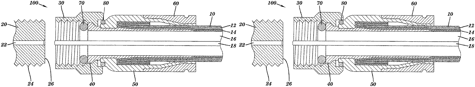
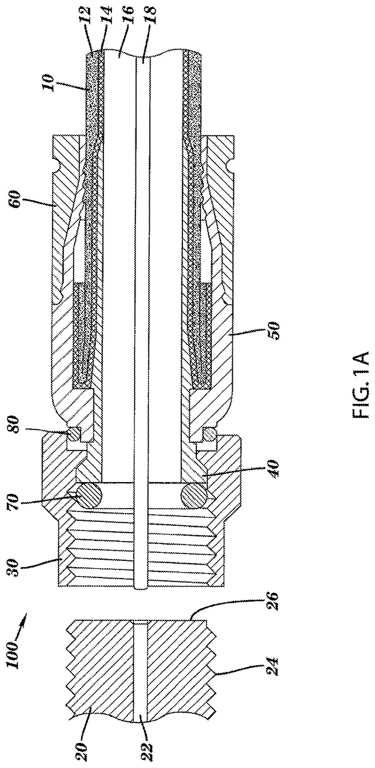
FIG. 1A depicts a sectional side view of a first embodiment of a connector;
FIG. 1B depicts a sectional side view of a second embodiment of a connector
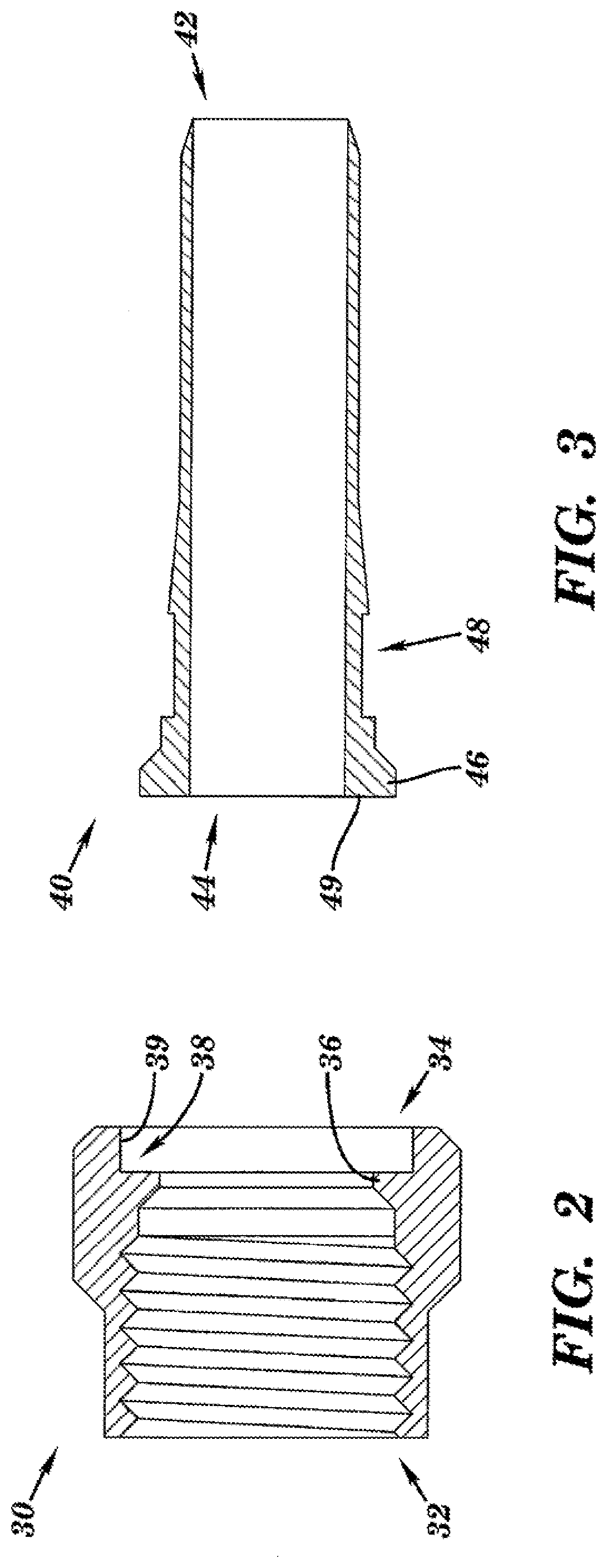
FIG. 2 depicts a sectional side view of an embodiment of a coupling member;
FIG. 3 depicts a sectional side view of an embodiment of a post;
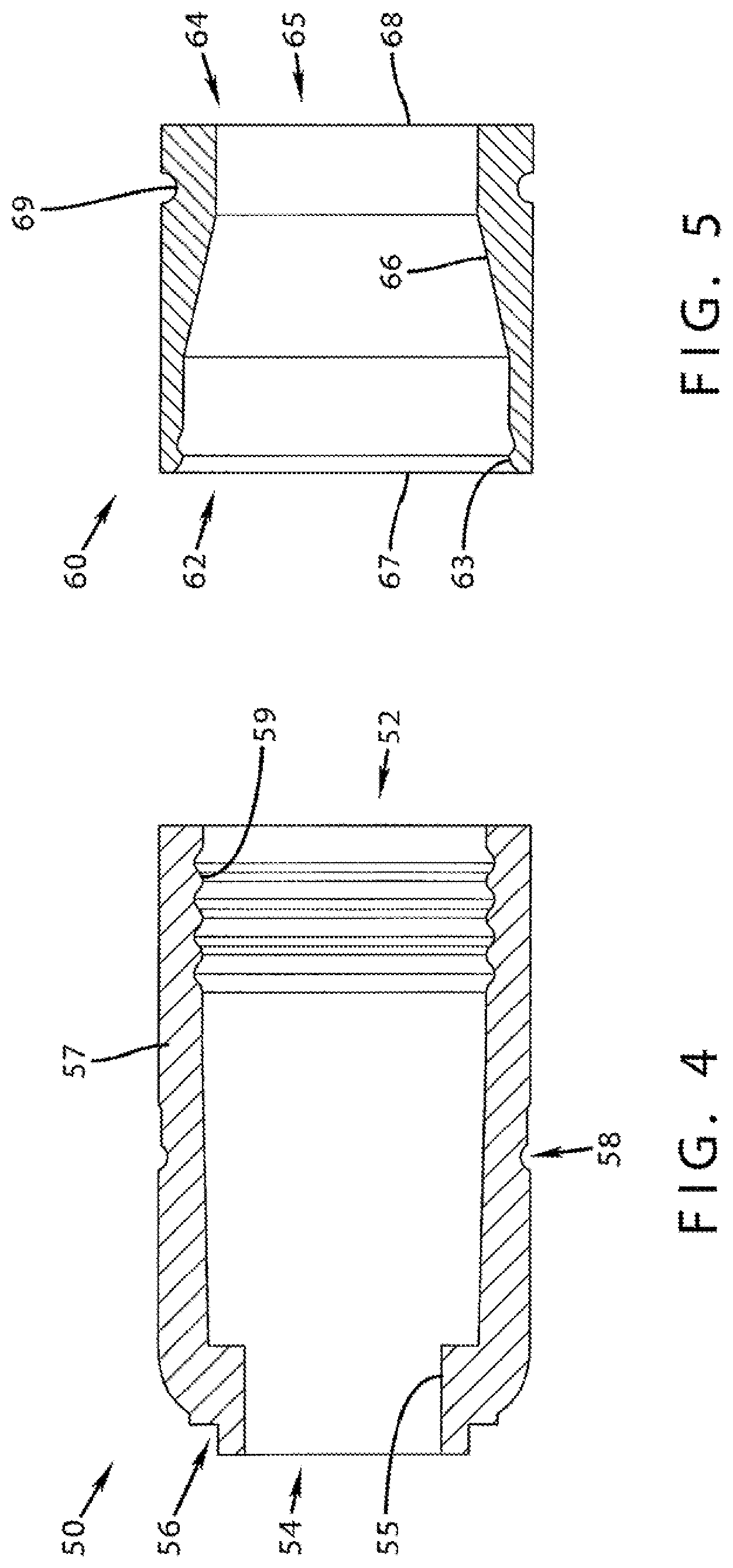
FIG. 4 depicts a sectional side view of an embodiment of a connector body;
FIG. 5 depicts a sectional side view of an embodiment of a fastener member;
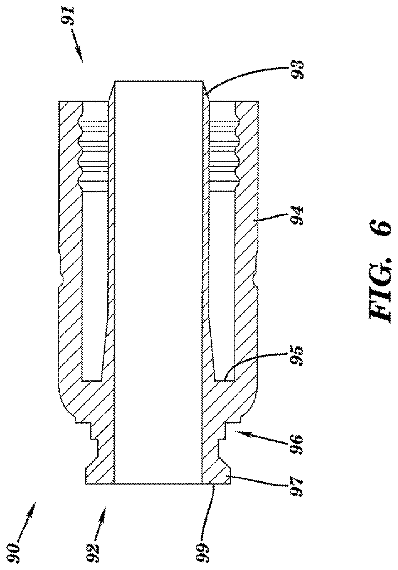
FIG. 6 depicts a sectional side view of an embodiment of a connector body having an integral post;
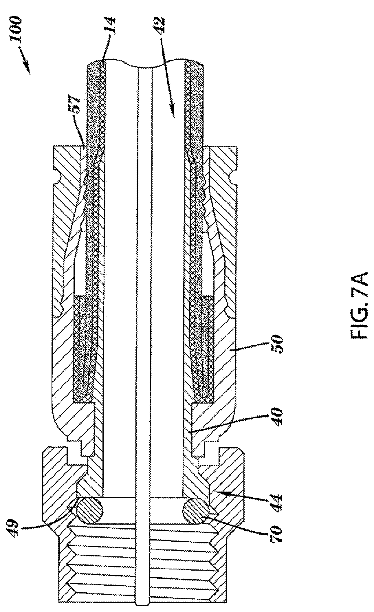
FIG. 7A depicts a sectional side view of the first embodiment of a connector configured with a conductive member proximate a second end of a post;
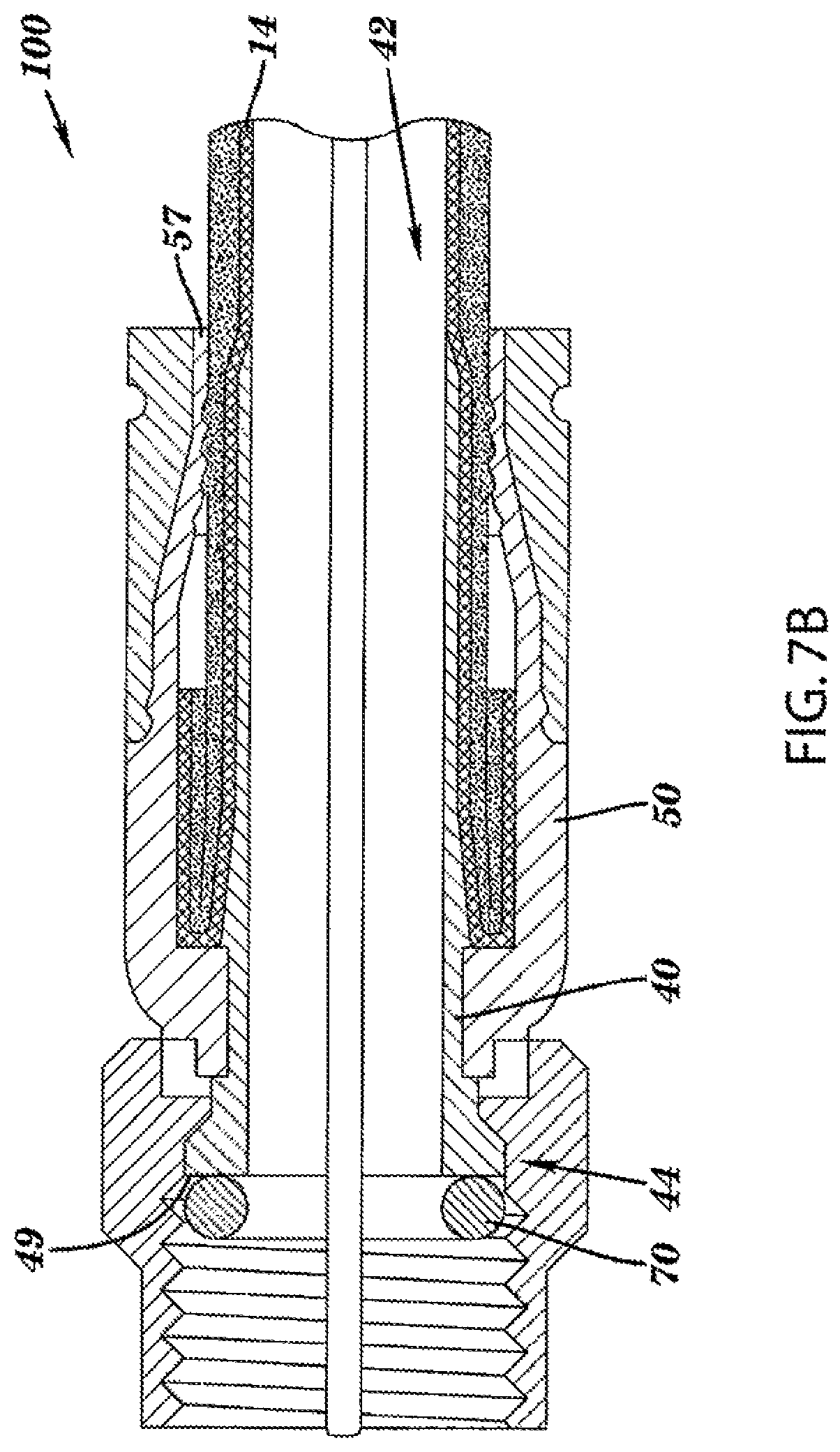
FIG. 7B depicts a sectional side view of the second embodiment of a connector configured with a conductive member proximate a second end of a post;
FIG. 8A depicts a sectional side view of the first embodiment of a connector configured with a conductive member proximate a second end of a connector body; and
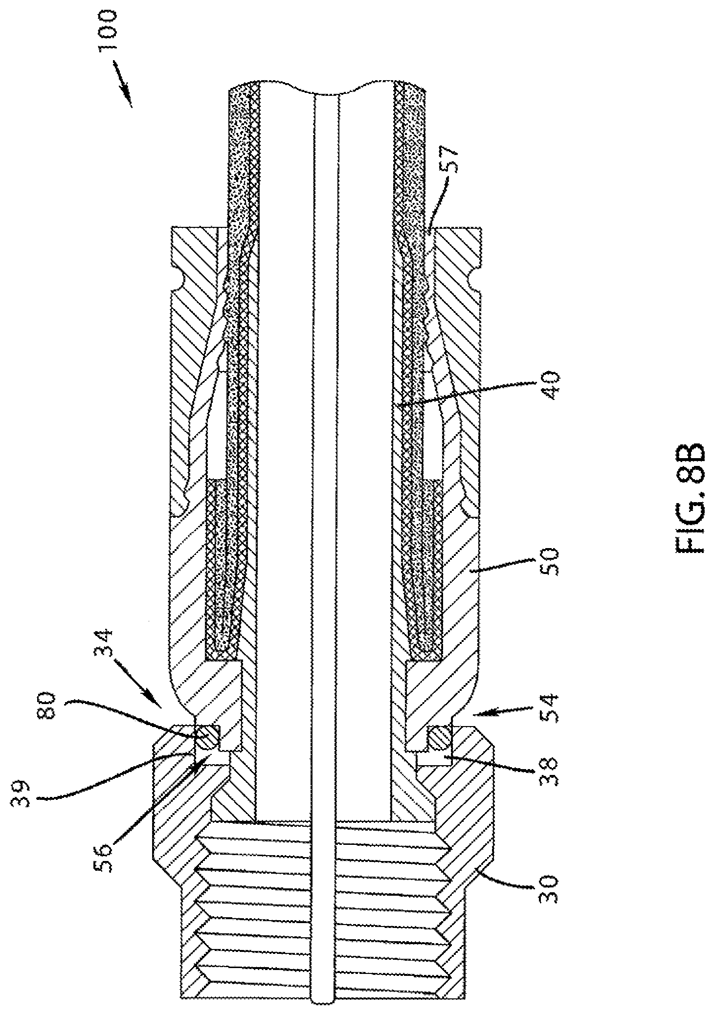
FIG. 8B depicts a sectional side view of the second embodiment of a connector configured with a conductive member proximate a second end of a connector body.
DETAILED DESCRIPTION OF EMBODIMENTS
Although certain embodiments of the present invention will be shown and described in detail, it should be understood that various changes and modifications may be made without departing from the scope of the appended claims. The scope of the present invention will in no way be limited to the number of constituting components, the materials thereof, the shapes thereof, the relative arrangement thereof, etc., and are disclosed simply as an example of an embodiment. The features and advantages of the present invention are illustrated in detail in the accompanying drawings, wherein like reference numerals refer to like elements throughout the drawings.
As a preface to the detailed description, it should be noted that, as used in this specification and the appended claims, the singular forms "a", "an" and "the" include plural referents, unless the context clearly dictates otherwise.
Referring to the drawings, FIGS. 1A and 1B depict a first and second embodiment of a connector 100. The connector 100 may include a coaxial cable 10 having a protective outer jacket 12, a conductive grounding shield 14, an interior dielectric 16 and a center conductor 18. The coaxial cable 10 may be prepared as embodied in FIGS. 1A and 1B by removing the protective outer jacket 12 and drawing back the conductive grounding shield 14 to expose a portion of the interior dielectric 16. Further preparation of the embodied coaxial cable 10 may include stripping the dielectric 16 to expose a portion of the center conductor 18. The protective outer jacket 12 is intended to protect the various components of the coaxial cable 10 from damage which may result from exposure to dirt or moisture and from corrosion. Moreover, the protective outer jacket 12 may serve in some measure to secure the various components of the coaxial cable 10 in a contained cable design that protects the cable 10 from damage related to movement during cable installation. The conductive grounding shield 14 may be comprised of conductive materials suitable for providing an electrical ground connection. Various embodiments of the shield 14 may be employed to screen unwanted noise. For instance, the shield 14 may comprise a metal foil wrapped around the dielectric 16, or several conductive strands formed in a continuous braid around the dielectric 16. Combinations of foil and/or braided strands may be utilized wherein the conductive shield 14 may comprise a foil layer, then a braided layer, and then a foil layer. Those in the art will appreciate that various layer combinations may be implemented in order for the conductive grounding shield 14 to effectuate an electromagnetic buffer helping to prevent ingress of environmental noise that may disrupt broadband communications. The dielectric 16 may be comprised of materials suitable for electrical insulation. It should be noted that the various materials of which all the various components of the coaxial cable 10 are comprised should have some degree of elasticity allowing the cable 10 to flex or bend in accordance with traditional broadband communications standards, installation methods and/or equipment. It should further be recognized that the radial thickness of the coaxial cable 10, protective outer jacket 12, conductive grounding shield 14, interior dielectric 16 and/or center conductor 18 may vary based upon generally recognized parameters corresponding to broadband communication standards and/or equipment.
Referring further to FIGS. 1A and 1B, the connector 100 may also include a coaxial cable interface port 20. The coaxial cable interface port 20 includes a conductive receptacle 22 for receiving a portion of a coaxial cable center conductor 18 sufficient to make adequate electrical contact. The coaxial cable interface port 20 may further comprise a threaded exterior surface 24. Although, various embodiments may employ a smooth as opposed to threaded exterior surface. In addition, the coaxial cable interface port 20 may comprise a mating edge 26. It should be recognized that the radial thickness and/or the length of the coaxial cable interface port 20 and/or the conductive receptacle 22 may vary based upon generally recognized parameters corresponding to broadband communication standards and/or equipment. Moreover, the pitch and height of threads which may be formed upon the threaded exterior surface 24 of the coaxial cable interface port 20 may also vary based upon generally recognized parameters corresponding to broadband communication standards and/or equipment. Furthermore, it should be noted that the interface port 20 may be formed of a single conductive material, multiple conductive materials, or may be configured with both conductive and non-conductive materials corresponding to the port's 20 electrical interface with a connector 100. For example, the threaded exterior surface may be fabricated from a conductive material, while the material comprising the mating edge 26 may be non-conductive or vice-versa. However, the conductive receptacle 22 should be formed of a conductive material. Further still, it will be understood by those of ordinary skill that the interface port 20 may be embodied by a connective interface component of a communications modifying device such as a signal splitter, a cable line extender, a cable network module and/or the like.
Referring still further to FIGS. 1A and 1B, an embodiment of the connector 100 may further comprise a coupling member 30, a post 40, a connector body 50, a fastener member 60, a conductively coated mating edge member such as O-ring 70, and/or a connector body conductive member, such as O-ring 80, and means for conductively sealing and electrically coupling the connector body 50 and coupling member 30. The means for conductively sealing and electrically coupling the connector body 50 and coupling member 30 is the employment of the connector body conductive member 80 positioned in a location so as to make a physical seal and effectuate electrical contact between the connector body 50 and coupling member 30.
With additional reference to the drawings, FIG. 2 depicts a sectional side view of an embodiment of a coupling member 30 having a first end 32 and opposing second end 34. The coupling element 30 may be a nut, a threaded nut, port coupling element, rotatable port coupling element, and the like. The coupling element 30 may include an inner surface, and an outer surface; the inner surface of the coupling element 30 may be a threaded configuration, the threads having a pitch and depth corresponding to a threaded port, such as interface port 20. In other embodiments, the inner surface of the coupling element 30 may not include threads, and may be axially inserted over an interface port, such as port 20. The coupling element 30 may be rotatably secured to the post 40 to allow for rotational movement about the post 40. The coupling member 30 may comprise an internal lip 36 located proximate the second end 34 and configured to hinder axial movement of the post 40 (shown in FIGS. 1A and 1B). Furthermore, the coupling member 30 may comprise a cavity 38 extending axially from the edge of second end 34 and partial defined and bounded by the internal lip 36. The cavity 38 may also be partially defined and bounded by an outer internal wall 39. Embodiments of the coupling member 30 may touch or physically contact the connector body 50 while operably configured, such as when connector 100 is threaded and/or advanced onto port 20, as shown in FIG. 1B. Alternatively, embodiments of the coupling member 30 may not touch or physically contact the connector body 50 while operably configured, such as when connector 100 is threaded and/or advanced onto port 20, as shown in FIG. 1A. For instance, electrical continuity may be established and maintained through the connector 100 (e.g. between the coupling member 30 and the post 40) while the coupling member 30 does not touch the connector body 50. The coupling member 30 may be formed of conductive materials facilitating grounding through the connector. Accordingly the coupling member 30 may be configured to extend an electromagnetic buffer by electrically contacting conductive surfaces of an interface port 20 when a connector 100 (shown in FIGS. 1A and 1B) is advanced onto the port 20. The coupling member 30 may also be in physical and electrical contact with the conductively coated mating edge member 70. Embodiments of the conductively coated mating edge member 70 may be disposed within the generally axial opening of the coupling member 30, and may physically contact the inner surface of the coupling member 30 proximate the mating edge 46 of the post 40. Other embodiments of the conductively coated mating edge member 70 may not physically contact the inner surface of the coupling member 30 until deformation of the conductively coated mating edge member 70 occurs. Deformation may occur when the connector 100 is threaded onto the port 20 a sufficient distance such that the post 40 and the port 20 act to compress the conductively coated mating edge member 70. The physical and electrical contact between the conductively coated mating edge member 70 may establish and maintain electrical continuity between the coupler member 30 and the post 40 to extend a RF shield and grounding through the connector 100. In addition, the coupling member 30 may be formed of non-conductive material and function only to physically secure and advance a connector 100 onto an interface port 20. Moreover, the coupling member 30 may be formed of both conductive and non-conductive materials. For example the internal lip 36 may be formed of a polymer, while the remainder of the nut 30 may be comprised of a metal or other conductive material. In addition, the coupling member 30 may be formed of metals or polymers or other materials that would facilitate a rigidly formed body. Manufacture of the coupling member 30 may include casting, extruding, cutting, turning, tapping, drilling, injection molding, blow molding, or other fabrication methods that may provide efficient production of the component.
With further reference to the drawings, FIG. 3 depicts a sectional side view of an embodiment of a post 40. The post 40 may comprise a first end 42 and opposing second end 44. Furthermore, the post 40 may comprise a flange 46 operatively configured to contact internal lip 36 of coupling member 30 (shown in FIG. 2) thereby facilitating the prevention of axial movement of the post beyond the contacted internal lip 36. Further still, an embodiment of the post 40 may include a surface feature 48 such as a shallow recess, detent, cut, slot, or trough. Additionally, the post 40 may include a mating edge 49. The mating edge 49 may be configured to make physical and/or electrical contact with an interface port 20 or conductively coated mating edge member or O-ring 70 (shown in FIGS. 1A and 1B). The post 40 should be formed such that portions of a prepared coaxial cable 10 including the dielectric 16 and center conductor 18 (shown in FIGS. 1A and 1B) may pass axially into the first end 42 and/or through the body of the post 40. Moreover, the post 40 should be dimensioned such that the post 40 may be inserted into an end of the prepared coaxial cable 10, around the dielectric 16 and under the protective outer jacket 12 and conductive grounding shield 14. Accordingly, where an embodiment of the post 40 may be inserted into an end of the prepared coaxial cable 10 under the drawn back conductive grounding shield 14 substantial physical and/or electrical contact with the shield 14 may be accomplished thereby facilitating grounding through the post 40. The post 40 may be formed of metals or other conductive materials that would facilitate a rigidly formed body. In addition, the post 40 may also be formed of non-conductive materials such as polymers or composites that facilitate a rigidly formed body. In further addition, the post may be formed of a combination of both conductive and non-conductive materials. For example, a metal coating or layer may be applied to a polymer of other non-conductive material. Manufacture of the post 40 may include casting, extruding, cutting, turning, drilling, injection molding, spraying, blow molding, or other fabrication methods that may provide efficient production of the component.
With continued reference to the drawings, FIG. 4 depicts a sectional side view of a connector body 50. The connector body 50 may comprise a first end 52 and opposing second end 54. Moreover, the connector body may include an internal annular lip 55 configured to mate and achieve purchase with the surface feature 48 of post 40 (shown in FIG. 3). In addition, the connector body 50 may include an outer annular recess 56 located proximate the second end 54. Furthermore, the connector body may include a semi-rigid, yet compliant outer surface 57, wherein the outer surface 57 may include an annular detent 58. The outer surface 57 may be configured to form an annular seal when the first end 52 is deformably compressed against a received coaxial cable 10 by a fastener member 60 (shown in FIGS. 1A and 1B). Further still, the connector body 50 may include internal surface features 59, such as annular serrations formed proximate the first end 52 of the connector body 50 and configured to enhance frictional restraint and gripping of an inserted and received coaxial cable 10. The connector body 50 may be formed of materials such as, polymers, bendable metals or composite materials that facilitate a semi-rigid, yet compliant outer surface 57. Further, the connector body 50 may be formed of conductive or non-conductive materials or a combination thereof. Manufacture of the connector body 50 may include casting, extruding, cutting, turning, drilling, injection molding, spraying, blow molding, or other fabrication methods that may provide efficient production of the component.
Referring further to the drawings, FIG. 5 depicts a sectional side view of an embodiment of a fastener member 60 in accordance with the present invention. The fastener member 60 may have a first end 62 and opposing second end 64. In addition, the fastener member 60 may include an internal annular protrusion 63 located proximate the first end 62 of the fastener member 60 and configured to mate and achieve purchase with the annular detent 58 on the outer surface 57 of connector body 50 (shown in FIG. 4). Moreover, the fastener member 60 may comprise a central passageway 65 defined between the first end 62 and second end 64 and extending axially through the fastener member 60. The central passageway 65 may comprise a ramped surface 66 which may be positioned between a first opening or inner bore 67 having a first diameter positioned proximate with the first end 62 of the fastener member 60 and a second opening or inner bore 68 having a second diameter positioned proximate with the second end 64 of the fastener member 60. The ramped surface 66 may act to deformably compress the outer surface 57 of a connector body 50 when the fastener member 60 is operated to secure a coaxial cable 10 (shown in FIGS. 1A and 1B). Additionally, the fastener member 60 may comprise an exterior surface feature 69 positioned proximate with the second end 64 of the fastener member 60. The surface feature 69 may facilitate gripping of the fastener member 60 during operation of the connector 100 (see FIGS. 1A and 1B). Although the surface feature is shown as an annular detent, it may have various shapes and sizes such as a ridge, notch, protrusion, knurling, or other friction or gripping type arrangements. It should be recognized, by those skilled in the requisite art, that the fastener member 60 may be formed of rigid materials such as metals, polymers, composites and the like. Furthermore, the fastener member 60 may be manufactured via casting, extruding, cutting, turning, drilling, injection molding, spraying, blow molding, or other fabrication methods that may provide efficient production of the component.
Referring still further to the drawings, FIG. 6 depicts a sectional side view of an embodiment of an integral post connector body 90 in accordance with the present invention. The integral post connector body 90 may have a first end 91 and opposing second end 92. The integral post connector body 90 physically and functionally integrates post and connector body components of an embodied connector 100 (shown in FIGS. 1A and 1B). Accordingly, the integral post connector body 90 includes a post member 93. The post member 93 may render connector operability similar to the functionality of post 40 (shown in FIG. 3). For example, the post member 93 of integral post connector body 90 may include a mating edge 99 configured to make physical and/or electrical contact with an interface port 20 or conductively coated mating edge member or O-ring 70 (shown in FIGS. 1A and 1B). The post member 93 of integral should be formed such that portions of a prepared coaxial cable 10 including the dielectric 16 and center conductor 18 (shown in FIGS. 1A and 1B) may pass axially into the first end 91 and/or through the post member 93. Moreover, the post member 93 should be dimensioned such that a portion of the post member 93 may be inserted into an end of the prepared coaxial cable 10, around the dielectric 16 and under the protective outer jacket 12 and conductive grounding shield 14. Further, the integral post connector body 90 includes an outer connector body surface 94. The outer connector body surface 94 may render connector 100 operability similar to the functionality of connector body 50 (shown in FIG. 4). Hence, outer connector body surface 94 should be semi-rigid, yet compliant. The outer connector body surface 94 may be configured to form an annular seal when compressed against a coaxial cable 10 by a fastener member 60 (shown in FIGS. 1A and 1B). In addition, the integral post connector body 90 may include an interior wall 95. The interior wall 95 may be configured as an unbroken surface between the post member 93 and outer connector body surface 94 of integral post connector body 90 and may provide additional contact points for a conductive grounding shield 14 of a coaxial cable 10. Furthermore, the integral post connector body 90 may include an outer recess formed proximate the second end 92. Further still, the integral post connector body 90 may comprise a flange 97 located proximate the second end 92 and operatively configured to contact internal lip 36 of coupling member 30 (shown in FIG. 2) thereby facilitating the prevention of axial movement of the integral post connector body 90 with respect to the coupling member 30. The integral post connector body 90 may be formed of materials such as, polymers, bendable metals or composite materials that facilitate a semi-rigid, yet compliant outer connector body surface 94. Additionally, the integral post connector body 90 may be formed of conductive or non-conductive materials or a combination thereof. Manufacture of the integral post connector body 90 may include casting, extruding, cutting, turning, drilling, injection molding, spraying, blow molding, or other fabrication methods that may provide efficient production of the component.
With continued reference to the drawings, FIGS. 7A and 7B depict a sectional side view of a first and second embodiment of a connector 100 configured with a conductively coated mating edge member 70 proximate a second end 44 of a post 40. The conductively coated mating edge member 70 may be configured to reside within a coupling member 30 of the connector 100, the conductively coated member 70 positioned to physically and electrically contact the mating edge of the post 40. The conductively coated mating edge member 70 should be conductive. For instance, the conductively coated elastomeric member 70 should exhibit levels of electrical and RF conductivity to facilitate grounding/shielding through the connector 100. Additionally, embodiments of the conductively coated mating edge member 70 may include a conductive coating or a partial conductive coating. For purposes of conductivity, the conductive coating may cover the entire outer surface of the coated mating edge member 70, or may partially cover the outer surface of the coated mating edge member 70. For example, embodiments of the coated mating edge member 70 may include one or more strips/portions of conductive coating spaced apart in a poloidal direction around the outer surface of the coated mating edge member 70. In another embodiment, the coated mating edge member 70 may include one or more strips/portions of conductive coating spaced apart in a toroidal direction around the outer surface of the mating edge member 70. Embodiments of the coated mating edge member 70 may include various configurations of conductive coating, including a weave-like pattern or a combination of rings and strips along both the poloidal and toroidal direction of the coated member 70. Coating the coated mating edge member 70 with a conductive coating can obtain high levels of electrical and RF conductivity from the conductively coated mating edge member 70 which can be used to extend a RF shield/grounding path through the connector 100.
Moreover, coating the coated mating edge member 70 may involve applying (e.g. spraying and/or spraycoating with an airbrush) a thin layer of conductive coating on the outer surface of the coated mating edge member 70. Because only the outer surface of the coated mating edge member 70 is coated with a conductive coating, the entire cross-section of the coated mating edge member 70 need not be conductive (i.e. not a bulk conductive member). Thus, the coated mating edge member 70 may be formed form non-conductive elastomeric materials, such as silicone rubber having properties characteristic of elastomeric materials, yet may exhibit electrical and RF conductivity properties once the conductive coating is applied to at least a portion of the coated mating edge member 70. Embodiments of the conductive coating may be a conductive ink, a silver-based ink, and the like, which may be thinned out from a paste-like substance. Thinning out the conductive coating for application on the coated mating edge member 70 may involve using a reactive top coat as a thinning agent, such as a mixture of liquid silicone rubber topcoat, to reduce hydrocarbon off-gassing during the thinning process; the reactive topcoat as a thinning agent may also act as a bonding agent to the outer surface (e.g. silicone rubber) of the coated mating edge member 70. Alternatively, the conductive coating may be thinned with an organic solvent as a thinning agent. The application of a conductive coating onto the elastomeric outer surface or portions of the coated mating edge member 70 may result in a highly conductive and highly flexible skin or conductive layer on the outer surface of the coated mating edge member 70. Thus, a continuous electrical ground/shielding path may be established between the post 40, the coated mating edge member 70, and an interface port 20 due to the conductive properties shared by the post 40, coated mating edge member 70, and the port 20, while also forming a seal proximate the mating edge of the post 40.
The coated mating edge member 70 may comprise a substantially circinate torus or toroid structure adapted to fit within the internal threaded portion of coupling member 30 such that the coated mating edge member 70 may make contact with and/or reside continuous with a mating edge 49 of a post 40 when operatively attached to post 40 of connector 100. For example, one embodiment of the conductively coated mating edge member 70 may be an O-ring. The conductively coated mating edge member 70 may facilitate an annular seal between the coupling member 30 and post 40 thereby providing a physical barrier to unwanted ingress of moisture and/or other environmental contaminates. Moreover, the conductively coated mating edge member 70 may facilitate electrical coupling of the post 40 and coupling member 30 by extending therebetween an unbroken electrical circuit. In addition, the conductively coated mating edge member 70 may facilitate grounding of the connector 100, and attached coaxial cable (shown in FIG. 1), by extending the electrical connection between the post 40 and the coupling member 30. Furthermore, the conductively coated mating edge member 70 may effectuate a buffer preventing ingress of electromagnetic noise between the coupling member 30 and the post 40. The conductively coated mating edge member or O-ring 70 may be provided to users in an assembled position proximate the second end 44 of post 40, or users may themselves insert the conductively coated mating edge conductive O-ring 70 into position prior to installation on an interface port 20 (shown in FIGS. 1A and 1B). Additionally, the conductively coated mating edge member 70 may be formed of materials such including but not limited to conductive polymers, plastics, conductive elastomers, elastomeric mixtures, composite materials having conductive properties, soft metals, conductive rubber, and/or the like and/or any workable combination thereof, that may or may not need to be coated with a conductive coating as described supra. Those skilled in the art would appreciate that the conductively coated mating edge member 70 may be fabricated by extruding, coating, molding, injecting, cutting, turning, elastomeric batch processing, vulcanizing, mixing, stamping, casting, and/or the like and/or any combination thereof in order to provide efficient production of the component.
With still further continued reference to the drawings, FIGS. 8A and 8B depict a sectional side view of a first and a second embodiment of a connector 100 configured with a connector body conductive member 80 proximate a second end 54 of a connector body 50. The connector body conductive member 80 should be formed of a conductive material. Such materials may include, but are not limited to conductive polymers, plastics, elastomeric mixtures, composite materials having conductive properties, soft metals, conductive rubber, and/or the like and/or any workable combination thereof. The connector body conductive member 80 may comprise a substantially circinate torus or toroid structure, or other ring-like structure. For example, an embodiment of the connector body conductive member 80 may be an O-ring configured to cooperate with the annular recess 56 proximate the second end 54 of connector body 50 and the cavity 38 extending axially from the edge of second end 34 and partially defined and bounded by an outer internal wall 39 of coupling member 30 such that the connector body conductive O-ring 80 may make contact with and/or reside contiguous with the annular recess 56 of connector body 50 and outer internal wall 39 of coupling member 30 when operatively attached to post 40 of connector 100. The connector body conductive member 80 may facilitate an annular seal between the coupling member 30 and connector body 50 thereby providing a physical barrier to unwanted ingress of moisture and/or other environmental contaminates. Moreover, the connector body conductive member 80 may facilitate electrical coupling of the connector body 50 and coupling member 30 by extending therebetween an unbroken electrical circuit. In addition, the connector body conductive member 80 may facilitate grounding of the connector 100, and attached coaxial cable (shown in FIGS. 1A and 1B), by extending the electrical connection between the connector body 50 and the coupling member 30. Furthermore, the connector body conductive member 80 may effectuate a buffer preventing ingress of electromagnetic noise between the coupling member 30 and the connector body 50. It should be recognized by those skilled in the relevant art that the connector body conductive member 80, like the conductively coated mating edge member 70, may be manufactured by extruding, coating, molding, injecting, cutting, turning, elastomeric batch processing, vulcanizing, mixing, stamping, casting, and/or the like and/or any combination thereof in order to provide efficient production of the component. I should be further recognized that the connector body conductive member 80 may also be conductively coated like the conductively coated mating edge member 70. For example, the connector body conductive member 80 may include a conductive coating or a partial conductive coating around the outer surface of the connector body conductive member 80.
With reference to FIGS. 1A, 1B, and 6-8B, either or both of the conductively coated mating edge member or O-ring 70 and connector body conductive member or O-ring 80 may be utilized in conjunction with an integral post connector body 90. For example, the conductively coated mating edge member 70 may be inserted within a coupling member 30 such that it contacts the mating edge 99 of integral post connector body 90 as implemented in an embodiment of connector 100. By further example, the connector body conductive member 80 may be positioned to cooperate and make contact with the recess 96 of connector body 90 and the outer internal wall 39 of an operably attached coupling member 30 of an embodiment of a connector 100. Those in the art should recognize that embodiments of the connector 100 may employ both the conductively coated mating edge member 70 and the connector body conductive member 80 in a single connector 100. Accordingly the various advantages attributable to each of the conductively coated mating edge member 70 and the connector body conductive member 80 may be obtained.
A method for grounding a coaxial cable 10 through a connector 100 is now described with reference to FIGS. 1A and 1B which depict a sectional side view of a first and a second embodiment of a connector 100. A coaxial cable 10 may be prepared for connector 100 attachment. Preparation of the coaxial cable 10 may involve removing the protective outer jacket 12 and drawing back the conductive grounding shield 14 to expose a portion of the interior dielectric 16. Further preparation of the embodied coaxial cable 10 may include stripping the dielectric 16 to expose a portion of the center conductor 18. Various other preparatory configurations of coaxial cable 10 may be employed for use with connector 100 in accordance with standard broadband communications technology and equipment. For example, the coaxial cable may be prepared without drawing back the conductive grounding shield 14, but merely stripping a portion thereof to expose the interior dielectric 16.
With continued reference to FIGS. 1A and 1B and additional reference to FIGS. 7A and 7B, further depiction of a method for grounding a coaxial cable 10 through a connector 100 is described. A connector 100 including a post 40 having a first end 42 and second end 44 may be provided. Moreover, the provided connector may include a connector body 50 and a conductively coated mating edge member 70 located proximate the second end 44 of post 40. The proximate location of the conductively coated mating edge member 70 should be such that the conductively coated mating edge member 70 makes physical and electrical contact with post 40. In one embodiment, the conductively coated mating edge member or O-ring 70 may be inserted into a coupling member 30 until it abuts the mating edge 49 of post 40. However, other embodiments of connector 100 may locate the conductively coated mating edge member 70 at or very near the second end 44 of post 40 without insertion of the conductively coated mating edge member 70 into a coupling member 30.
Grounding may be further attained by fixedly attaching the coaxial cable 10 to the connector 100. Attachment may be accomplished by insetting the coaxial cable 10 into the connector 100 such that the first end 42 of post 40 is inserted under the conductive grounding sheath or shield 14 and around the dielectric 16. Where the post 40 is comprised of conductive material, a grounding connection may be achieved between the received conductive grounding shield 14 of coaxial cable 10 and the inserted post 40. The ground may extend through the post 40 from the first end 42 where initial physical and electrical contact is made with the conductive grounding sheath 14 to the mating edge 49 located at the second end 44 of the post 40. Once, received, the coaxial cable 10 may be securely fixed into position by radially compressing the outer surface 57 of connector body 50 against the coaxial cable 10 thereby affixing the cable into position and sealing the connection. The radial compression of the connector body 50 may be effectuated by physical deformation caused by a fastener member 60 that may compress and lock the connector body 50 into place. Moreover, where the connector body 50 is formed of materials having and elastic limit, compression may be accomplished by crimping tools, or other like means that may be implemented to permanently deform the connector body 50 into a securely affixed position around the coaxial cable 10.
As an additional step, grounding of the coaxial cable 10 through the connector 100 may be accomplished by advancing the connector 100 onto an interface port 20 until a surface of the interface port mates with the conductively coated mating edge member 70. Because the conductively coated mating edge member 70 is located such that it makes physical and electrical contact with post 40, grounding may be extended from the post 40 through the conductively coated mating edge member 70 and then through the mated interface port 20. Accordingly, the interface port 20 should make physical and electrical contact with the conductively coated mating edge member 70. The conductively coated mating edge member 70 may function as a conductive seal when physically pressed against the interface port 20. Advancement of the connector 100 onto the interface port 20 may involve the threading on of attached coupling member 30 of connector 100 until a surface of the interface port 20 abuts the conductively coated mating edge member 70 and axial progression of the advancing connector 100 is hindered by the abutment. However, it should be recognized that embodiments of the connector 100 may be advanced onto an interface port 20 without threading and involvement of a coupling member 30. Once advanced until progression is stopped by the conductive sealing contact of conductively coated mating edge member 70 with interface port 20, the connector 100 may be shielded from ingress of unwanted electromagnetic interference. Moreover, grounding may be accomplished by physical advancement of various embodiments of the connector 100 wherein a conductively coated mating edge member 70 facilitates electrical connection of the connector 100 and attached coaxial cable 10 to an interface port 20.
A method for electrically coupling a connector 100 and a coaxial cable 10 is now described with reference to FIGS. 1A and 1B. A coaxial cable 10 may be prepared for fastening to connector 100. Preparation of the coaxial cable 10 may involve removing the protective outer jacket 12 and drawing back the conductive grounding shield 14 to expose a portion of the interior dielectric 16. Further preparation of the embodied coaxial cable 10 may include stripping the dielectric 16 to expose a portion of the center conductor 18.
With continued reference to FIGS. 1A and 1B and additional reference to FIGS. 8A and 8B, further depiction of a method for electrically coupling a coaxial cable 10 and a connector 100 is described. A connector 100 including a connector body 50 and a coupling member 30 may be provided. Moreover, the provided connector may include a connector body conductive member or seal 80. The connector body conductive member or seal 80 should be configured and located such that the connector body conductive member 80 electrically couples and physically seals the connector body 50 and coupling member 30. In one embodiment, the connector body conductive member or seal 80 may be located proximate a second end 54 of a connector body 50. The connector body conductive member 80 may reside within a cavity 38 of coupling member 30 such that the connector body conductive member 80 lies between the connector body 50 and coupling member 30 when attached. Furthermore, the particularly embodied connector body conductive member 80 may physically contact and make a seal with outer internal wall 39 of coupling member 30. Moreover, the connector body conductive member 80 may physically contact and seal against the surface of connector body 50. Accordingly, where the connector body 50 is comprised of conductive material and the coupling member 30 is comprised of conductive material, the connector body conductive member 80 may electrically couple the connector body 50 and the coupling member 30. Various other embodiments of connector 100 may incorporate a connector body conductive member 80 for the purpose of electrically coupling a coaxial cable 10 and connector 100. For example, the connector body conductive member, such as O-ring 80, may be located in a recess on the outer surface of the coupling member 30 such that the connector body conductive O-ring 80 lies between the nut and an internal surface of connector body 50, thereby facilitating a physical seal and electrical couple.
Electrical coupling may be further accomplished by fixedly attaching the coaxial cable 10 to the connector 100. The coaxial cable 10 may be inserted into the connector body 50 such that the conductive grounding shield 14 makes physical and electrical contact with and is received by the connector body 50. In one embodiment of the connector 100, the drawn back conductive grounding shield 14 may be pushed against the inner surface of the connector body 50 when inserted. Once received, or operably inserted into the connector 100, the coaxial cable 10 may be securely set into position by compacting and deforming the outer surface 57 of connector body 50 against the coaxial cable 10 thereby affixing the cable into position and sealing the connection. Compaction and deformation of the connector body 50 may be effectuated by physical compression caused by a fastener member 60, wherein the fastener member 60 constricts and locks the connector body 50 into place. Moreover, where the connector body 50 is formed of materials having and elastic limit, compaction and deformation may be accomplished by crimping tools, or other like means that may be implemented to permanently contort the outer surface 57 of connector body 50 into a securely affixed position around the coaxial cable 10.
A further method step of electrically coupling the coaxial cable 10 and the connector 100 may be accomplished by completing an electromagnetic shield by threading the coupling member 30 onto a conductive interface port 20. Where the connector body 50 and coupling member 30 are formed of conductive materials, an electrical circuit may be formed when the conductive interface port 20 contacts the coupling member 30 because the connector body conductive member 80 extends the electrical circuit and facilitates electrical contact between the coupling member 30 and connector body 50. Moreover, the realized electrical circuit works in conjunction with physical screening performed by the connector body 50 and coupling member 30 as positioned in barrier-like fashion around a coaxial cable 10 when fixedly attached to a connector 100 to complete an electromagnetic shield where the connector body conductive member 80 also operates to physically screen electromagnetic noise. Thus, when threaded onto an interface port 20, the completed electrical couple renders electromagnetic protection, or EMI shielding, against unwanted ingress of environmental noise into the connector 100 and coaxial cable 10.
Additionally, a method of facilitating electrical continuity through a coaxial cable connector 100, the coaxial cable 10 having a center conductor 18 surrounded by a dielectric 16, the dielectric 16 being surrounded by a conductive grounding shield 14, the conductive grounding shield 14 being surrounded by a protective outer jacket 12, may include the steps of providing the connector 100, wherein the connector 100 includes a connector body 50, a post 40 having a mating edge 46, and a conductively coated member 70 positioned to physically and electrically contact an inner surface of the coupling member 30 to facilitate electrical continuity between the coupling member 30 and the post 40 to help shield against ingress of unwanted electromagnetic interference, fixedly attaching the coaxial cable 10 to the connector 100, and advancing the connector 100 onto an interface port 20.
While this invention has been described in conjunction with the specific embodiments outlined above, it is evident that many alternatives, modifications and variations will be apparent to those skilled in the art. Accordingly, the embodiments of the invention as set forth above are intended to be illustrative, not limiting. Various changes may be made without departing from the spirit and scope of the invention as defined in the following claims.
* * * * *
References
D00000
D00001
D00002
D00003
D00004
D00005
D00006
D00007
D00008
D00009
XML
uspto.report is an independent third-party trademark research tool that is not affiliated, endorsed, or sponsored by the United States Patent and Trademark Office (USPTO) or any other governmental organization. The information provided by uspto.report is based on publicly available data at the time of writing and is intended for informational purposes only.
While we strive to provide accurate and up-to-date information, we do not guarantee the accuracy, completeness, reliability, or suitability of the information displayed on this site. The use of this site is at your own risk. Any reliance you place on such information is therefore strictly at your own risk.
All official trademark data, including owner information, should be verified by visiting the official USPTO website at www.uspto.gov. This site is not intended to replace professional legal advice and should not be used as a substitute for consulting with a legal professional who is knowledgeable about trademark law.