Breathing assistance apparatus
McAuley , et al. November 24, 2
U.S. patent number 10,842,964 [Application Number 16/775,154] was granted by the patent office on 2020-11-24 for breathing assistance apparatus. This patent grant is currently assigned to Fisher & Paykel Healthcare Limited. The grantee listed for this patent is Fisher & Paykel Healthcare Limited. Invention is credited to Oliver Gleeson, Alastair Edwin McAuley, Craig Robert Prentice.
| United States Patent | 10,842,964 |
| McAuley , et al. | November 24, 2020 |
Breathing assistance apparatus
Abstract
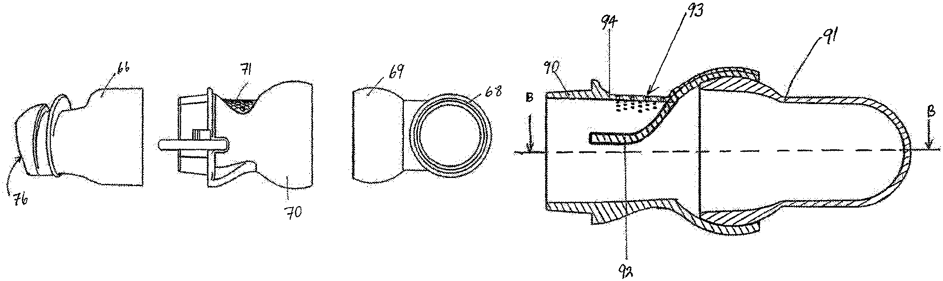
In one embodiment, a nasal cannula is shaped to fit within a user's nares, where the nasal cannula includes at least one prong allowing high flow delivery of humidified gases and creates positive airway pressure in the patient's airway. The prongs have angled ends such that, in use, gases flowing through the prongs are directed to the user's nasal passages. The nasal cannula body is partially swivelling and preferably has a ball joint connector. In another embodiment the nasal cannula may have at least one flared end prong that preferably seals within a patient's nare.
| Inventors: | McAuley; Alastair Edwin (Auckland, NZ), Prentice; Craig Robert (Auckland, NZ), Gleeson; Oliver (Auckland, NZ) | ||||||||||
|---|---|---|---|---|---|---|---|---|---|---|---|
| Applicant: |
|
||||||||||
| Assignee: | Fisher & Paykel Healthcare
Limited (Auckland, NZ) |
||||||||||
| Family ID: | 1000005200063 | ||||||||||
| Appl. No.: | 16/775,154 | ||||||||||
| Filed: | January 28, 2020 |
Prior Publication Data
| Document Identifier | Publication Date | |
|---|---|---|
| US 20200164169 A1 | May 28, 2020 | |
Related U.S. Patent Documents
| Application Number | Filing Date | Patent Number | Issue Date | ||
|---|---|---|---|---|---|
| 16378212 | Apr 8, 2019 | ||||
| 15947021 | Apr 9, 2019 | 10252015 | |||
| 14333134 | May 22, 2018 | 9974914 | |||
| 10598026 | Jul 22, 2014 | 8783257 | |||
| PCT/NZ2005/000023 | Feb 18, 2005 | ||||
Foreign Application Priority Data
| Feb 23, 2004 [NZ] | 531332 | |||
| Aug 6, 2004 [NZ] | 534606 | |||
| Current U.S. Class: | 1/1 |
| Current CPC Class: | A61M 16/08 (20130101); A61M 16/0057 (20130101); A61M 16/0816 (20130101); A61M 16/0875 (20130101); A61M 16/0069 (20140204); A61M 16/0616 (20140204); A61M 16/0825 (20140204); A61M 16/109 (20140204); A61M 16/16 (20130101); A61M 16/0666 (20130101); A61M 16/024 (20170801); A61M 16/0683 (20130101); A61M 2205/0216 (20130101) |
| Current International Class: | A61M 16/06 (20060101); A61M 16/08 (20060101); A61M 16/16 (20060101); A61M 16/00 (20060101); A61M 16/10 (20060101) |
References Cited [Referenced By]
U.S. Patent Documents
| 301111 | July 1884 | Genese |
| 472238 | April 1892 | Van Orden |
| 577926 | March 1897 | Miller |
| 718470 | January 1903 | Jones |
| 751091 | February 1904 | Moran |
| 770013 | September 1904 | Linn |
| 1635545 | July 1927 | Drager |
| 2126755 | August 1938 | Dreyfus |
| 2228218 | January 1941 | Schwartz |
| 2241535 | May 1941 | Boothby et al. |
| 2296150 | September 1942 | Dockson et al. |
| 2353643 | July 1944 | Bulbulian |
| 2359506 | October 1944 | Battley et al. |
| 2388604 | November 1945 | Eisenbud |
| 2452845 | November 1948 | Fisher |
| 2508050 | May 1950 | Valente |
| 2693800 | November 1954 | Caldwell |
| 2738788 | March 1956 | Matheson et al. |
| 2843121 | July 1958 | Hudson |
| 2859748 | November 1958 | Hudson |
| 2875759 | March 1959 | Galleher |
| 2894506 | July 1959 | Rose |
| 2939458 | June 1960 | Lundquist |
| 3424633 | January 1969 | Corrigall et al. |
| 3490452 | January 1970 | Greenfield |
| 3599635 | August 1971 | Kenneth |
| 3682171 | August 1972 | Dali et al. |
| 3834682 | September 1974 | McPhee |
| 3850171 | November 1974 | Ball et al. |
| 3894562 | July 1975 | Mosley et al. |
| 3972321 | August 1976 | Proctor |
| 3977432 | August 1976 | Vidal |
| 3992720 | November 1976 | Nicolinas |
| 4090510 | May 1978 | Segersten |
| D250047 | October 1978 | Lewis et al. |
| D250131 | October 1978 | Lewis et al. |
| 4127130 | November 1978 | Naysmith |
| 4150464 | April 1979 | Tracy |
| D252322 | July 1979 | Johnson |
| 4201205 | May 1980 | Bartholomew |
| 4258710 | March 1981 | Reber |
| 4266540 | May 1981 | Panzik et al. |
| 4278082 | July 1981 | Blackmer |
| 4354488 | October 1982 | Bartos |
| 4367735 | January 1983 | Dali |
| 4378011 | March 1983 | Warncke et al. |
| 4437462 | March 1984 | Piljay |
| 4454880 | June 1984 | Muto et al. |
| 4574799 | March 1986 | Warncke et al. |
| 4603602 | August 1986 | Montesi |
| 4621632 | November 1986 | Bartels et al. |
| 4644974 | February 1987 | Zingg |
| 4676241 | June 1987 | Webb et al. |
| D293613 | January 1988 | Wingler |
| 4753233 | June 1988 | Grimes |
| 4782832 | November 1988 | Trimble et al. |
| 4836200 | June 1989 | Clark et al. |
| 4856508 | August 1989 | Tayebi |
| 4907584 | March 1990 | McGinnis |
| 4915104 | April 1990 | Marcy |
| 4915105 | April 1990 | Lee |
| 4919128 | April 1990 | Kopala et al. |
| 4938209 | July 1990 | Fry |
| 4941467 | July 1990 | Takata |
| 4944310 | July 1990 | Sullivan |
| D310431 | September 1990 | Bellm |
| 4958658 | September 1990 | Zajac |
| 4971051 | November 1990 | Toffolon |
| 4986269 | January 1991 | Hakkinen |
| 5010925 | April 1991 | Atkinson et al. |
| 5016625 | May 1991 | Hsu et al. |
| 5031261 | July 1991 | Fenner |
| 5042478 | August 1991 | Kopala et al. |
| D320677 | October 1991 | Kumagai et al. |
| D321419 | November 1991 | Wallace |
| 5062421 | November 1991 | Burns et al. |
| 5065756 | November 1991 | Rapoport |
| D322318 | December 1991 | Sullivan et al. |
| 5074297 | December 1991 | Venegas |
| 5094236 | March 1992 | Tayebi |
| 5113857 | May 1992 | Dickerman et al. |
| 5121745 | June 1992 | Israel et al. |
| 5148802 | September 1992 | Sanders et al. |
| 5164652 | November 1992 | Johnson et al. |
| 5231979 | August 1993 | Rose |
| 5243971 | September 1993 | Sullivan et al. |
| 5245995 | September 1993 | Sullivan et al. |
| D340317 | October 1993 | Cole |
| 5259377 | November 1993 | Schroeder |
| 5267556 | December 1993 | Feng |
| 5269296 | December 1993 | Landis et al. |
| 5315859 | May 1994 | Schommer |
| 5349949 | September 1994 | Schegerin |
| 5366805 | November 1994 | Fujiki et al. |
| D354128 | January 1995 | Rinehart |
| D355484 | February 1995 | Rinehart |
| 5400776 | March 1995 | Bartholomew |
| 5429683 | July 1995 | Le Mitouard |
| 5438979 | August 1995 | Johnson et al. |
| 5441046 | August 1995 | Starr et al. |
| 5449206 | September 1995 | Lockwood |
| 5449234 | September 1995 | Gipp et al. |
| 5458202 | October 1995 | Fellows et al. |
| 5460174 | October 1995 | Chang |
| 5477852 | December 1995 | Landis et al. |
| 5513634 | May 1996 | Jackson |
| 5518802 | May 1996 | Colvin et al. |
| 5533506 | July 1996 | Wood |
| 5542128 | August 1996 | Lomas |
| 5551419 | September 1996 | Froehlich et al. |
| 5558090 | September 1996 | James |
| 5570689 | November 1996 | Starr et al. |
| 5588423 | December 1996 | Smith |
| 5595174 | January 1997 | Gwaltney |
| 5601078 | February 1997 | Schaller et al. |
| D378610 | March 1997 | Reischel et al. |
| 5649532 | July 1997 | Griffiths |
| 5657752 | August 1997 | Landis et al. |
| 5662101 | September 1997 | Ogden et al. |
| 5664566 | September 1997 | Mcdonald et al. |
| 5687715 | November 1997 | Landis |
| 5690097 | November 1997 | Howard et al. |
| 5724965 | March 1998 | Handke et al. |
| 5752510 | May 1998 | Goldstein |
| 5755578 | May 1998 | Contant et al. |
| 5806727 | September 1998 | Joseph |
| 5807295 | September 1998 | Hutcheon et al. |
| 5746201 | December 1998 | Kidd |
| 5857460 | January 1999 | Popitz |
| 5884624 | March 1999 | Barnett et al. |
| 5904278 | May 1999 | Barlow et al. |
| 5918598 | July 1999 | Belfer |
| 5921239 | July 1999 | McCall |
| 5924420 | July 1999 | Reischel |
| 5941245 | August 1999 | Hannah et al. |
| 5943473 | August 1999 | Levine |
| 5953763 | September 1999 | Gouget |
| 5966745 | October 1999 | Schwartz et al. |
| 6016804 | January 2000 | Gleason et al. |
| 6017315 | January 2000 | Starr et al. |
| 6019101 | February 2000 | Cotner et al. |
| 6021528 | February 2000 | Jurga |
| 6039044 | March 2000 | Sullivan |
| 6050260 | April 2000 | Daniell et al. |
| 6112746 | September 2000 | Kwok et al. |
| 6116235 | September 2000 | Walters et al. |
| 6119693 | September 2000 | Kwok et al. |
| 6119694 | September 2000 | Correa et al. |
| 6135109 | October 2000 | Blasdell et al. |
| 6135432 | October 2000 | Hebblewhite et al. |
| 6192886 | February 2001 | Rudolph |
| D440302 | April 2001 | Wolfe |
| 6272933 | August 2001 | Gradon et al. |
| 6298850 | October 2001 | Argraves |
| 6302105 | October 2001 | Wickham et al. |
| 6341606 | January 2002 | Bordewick et al. |
| 6347631 | February 2002 | Hansen et al. |
| D455891 | April 2002 | Biedrzycki |
| 6398197 | June 2002 | Dickinson et al. |
| 6412487 | July 2002 | Gunaratnam et al. |
| 6412488 | July 2002 | Barnett |
| 6418928 | July 2002 | Bordewick et al. |
| 6427694 | August 2002 | Hecker et al. |
| 6431172 | August 2002 | Bordewick |
| 6435181 | August 2002 | Jones, Jr. et al. |
| 6439234 | August 2002 | Curti et al. |
| 6457473 | October 2002 | Brostrom et al. |
| 6467483 | October 2002 | Kopacko et al. |
| 6470886 | October 2002 | Jestrabek-Hart |
| 6478026 | November 2002 | Wood |
| 6484725 | November 2002 | Chi et al. |
| 6488664 | December 2002 | Solomon et al. |
| 6491034 | December 2002 | Gunaratnam et al. |
| 6513526 | February 2003 | Kwok et al. |
| 6526978 | March 2003 | Dominguez |
| 6530373 | March 2003 | Patron et al. |
| 6561188 | May 2003 | Ellis |
| 6561190 | May 2003 | Kwok |
| 6561191 | May 2003 | Kwok |
| 6581594 | June 2003 | Drew et al. |
| 6581601 | June 2003 | Ziaee |
| 6581602 | June 2003 | Kwok et al. |
| 6584977 | July 2003 | Serowski |
| 6588424 | July 2003 | Bardel |
| 6615832 | September 2003 | Chen |
| 6629531 | October 2003 | Gleason et al. |
| 6631718 | October 2003 | Lovell |
| 6634358 | October 2003 | Kwok et al. |
| 6637434 | October 2003 | Noble |
| 6644315 | November 2003 | Ziaee |
| 6651658 | November 2003 | Hill et al. |
| 6651663 | November 2003 | Barnett et al. |
| 6659102 | December 2003 | Sico |
| 6662803 | December 2003 | Gradon et al. |
| 6668828 | December 2003 | Figley et al. |
| D485905 | January 2004 | Moore |
| 6679257 | January 2004 | Robertson et al. |
| 6679265 | January 2004 | Strickland et al. |
| 6691707 | February 2004 | Gunaratnam et al. |
| 6712072 | March 2004 | Lang |
| 6736139 | May 2004 | Wix |
| 6772761 | August 2004 | Rucker, Jr. |
| 6796308 | September 2004 | Gunaratnam et al. |
| 6817362 | November 2004 | Gelinas et al. |
| 6823869 | November 2004 | Raje et al. |
| 6851425 | February 2005 | Jaffre et al. |
| 6851428 | February 2005 | Dennis |
| 6883177 | April 2005 | Ouellette et al. |
| 6892729 | May 2005 | Smith et al. |
| 6895965 | May 2005 | Scarberry et al. |
| 6907882 | June 2005 | Ging et al. |
| 6918390 | July 2005 | Lithgow et al. |
| 6951218 | October 2005 | Gradon et al. |
| 6953354 | October 2005 | Edirisuriya et al. |
| 6997187 | February 2006 | Wood et al. |
| 7004165 | February 2006 | Salcido |
| 7007696 | March 2006 | Palkon et al. |
| 7021311 | April 2006 | Gunaratnam et al. |
| D520140 | May 2006 | Chaggares |
| 7066179 | June 2006 | Eaton et al. |
| 7077126 | July 2006 | Kummer et al. |
| D526094 | August 2006 | Chen |
| 7096864 | August 2006 | Mayer et al. |
| D533269 | December 2006 | McAuley et al. |
| 7178525 | February 2007 | Matula, Jr. et al. |
| 7178528 | February 2007 | Lau |
| 7201169 | April 2007 | Wilkie et al. |
| 7207333 | April 2007 | Tohara |
| 7210481 | May 2007 | Lovell et al. |
| 7219669 | May 2007 | Lovell et al. |
| 7225811 | June 2007 | Ruiz et al. |
| 7255106 | August 2007 | Gallem et al. |
| 7287528 | October 2007 | Ho et al. |
| 7290546 | November 2007 | Sprinkle et al. |
| 7296575 | November 2007 | Radney |
| 7318437 | January 2008 | Gunaratnam et al. |
| 7353827 | April 2008 | Geist |
| 7357136 | April 2008 | Ho et al. |
| 7406966 | August 2008 | Wondka et al. |
| 7448386 | November 2008 | Ho et al. |
| 7487772 | February 2009 | Ging et al. |
| 7493902 | February 2009 | White et al. |
| D589139 | March 2009 | Guney |
| 7523754 | April 2009 | Lithgow et al. |
| D595841 | July 2009 | McAuley et al. |
| 7562658 | July 2009 | Madaus et al. |
| 7597100 | October 2009 | Ging |
| 7640934 | January 2010 | Zollinger et al. |
| 7658189 | February 2010 | Davidson et al. |
| 7665464 | February 2010 | Kopacko et al. |
| D612933 | March 2010 | Prentice |
| 7681575 | March 2010 | Wixey et al. |
| 7694677 | April 2010 | Tang |
| 7703457 | April 2010 | Barnett et al. |
| 7753051 | July 2010 | Burrow et al. |
| D623288 | September 2010 | Lubke |
| 7814911 | October 2010 | Bordewick et al. |
| 7827990 | November 2010 | Melidis et al. |
| 7856982 | December 2010 | Matula et al. |
| 7877817 | February 2011 | Ho |
| 7896003 | March 2011 | Matula et al. |
| 7931024 | April 2011 | Ho et al. |
| 7934501 | May 2011 | Fu |
| 7942150 | May 2011 | Guney et al. |
| 7992560 | August 2011 | Burton et al. |
| 8042539 | October 2011 | Chandran et al. |
| 8042541 | October 2011 | Amarasinghe et al. |
| 8109271 | February 2012 | Vandine et al. |
| 8136524 | March 2012 | Ging et al. |
| 8136525 | March 2012 | Lubke et al. |
| 8171933 | May 2012 | Xue et al. |
| D661796 | June 2012 | Andrews et al. |
| 8245711 | August 2012 | Matula et al. |
| 8371302 | February 2013 | Ging et al. |
| 8397727 | March 2013 | Ng et al. |
| 8443807 | May 2013 | McAuley et al. |
| D686313 | July 2013 | Matula et al. |
| 8479726 | July 2013 | McAuley |
| 8479741 | July 2013 | McAuley et al. |
| 8567404 | October 2013 | Davidson et al. |
| 8631793 | January 2014 | Omura et al. |
| 8631799 | January 2014 | Davenport |
| 8636005 | January 2014 | Gradon et al. |
| 8701667 | April 2014 | Ho et al. |
| 8714157 | May 2014 | McAuley et al. |
| 8720444 | May 2014 | Chang |
| 8757157 | June 2014 | Price et al. |
| 8783257 | July 2014 | McAuley et al. |
| 8869797 | October 2014 | Davidson et al. |
| 8869798 | October 2014 | Wells et al. |
| 8875709 | November 2014 | Davidson et al. |
| 8944061 | February 2015 | D'Souza et al. |
| 8950404 | February 2015 | Formica et al. |
| 8960196 | February 2015 | Henry |
| 9010331 | April 2015 | Lang et al. |
| 9027556 | May 2015 | Ng et al. |
| 9032955 | May 2015 | Lubke et al. |
| 9032956 | May 2015 | Scheiner et al. |
| 9072852 | July 2015 | McAuley et al. |
| 9095673 | August 2015 | Barlow et al. |
| 9119929 | September 2015 | McAuley et al. |
| 9119931 | September 2015 | D'Souza et al. |
| 9138555 | September 2015 | McAuley et al. |
| 9149596 | October 2015 | Valcic et al. |
| 9186474 | November 2015 | Rollins |
| 9242062 | January 2016 | Melidis et al. |
| 9292799 | March 2016 | McAuley et al. |
| 9295799 | March 2016 | McAuley et al. |
| 9302065 | April 2016 | Smith et al. |
| 9320566 | April 2016 | Alston, Jr. |
| 9320866 | April 2016 | McAuley et al. |
| 9333315 | May 2016 | McAuley et al. |
| 9339622 | May 2016 | McAuley et al. |
| 9339624 | May 2016 | McAuley |
| 9375545 | June 2016 | Darkin et al. |
| 9381316 | July 2016 | Ng et al. |
| 9457162 | October 2016 | Ging et al. |
| 9486601 | November 2016 | Stallard et al. |
| 9517317 | December 2016 | McAuley et al. |
| 9522246 | December 2016 | Frater et al. |
| 9539405 | January 2017 | McAuley et al. |
| 9550038 | January 2017 | McAuley et al. |
| 9561338 | February 2017 | McAuley et al. |
| 9561339 | February 2017 | McAuley et al. |
| 9744385 | August 2017 | Henry et al. |
| 9884160 | February 2018 | McAuley et al. |
| 9901699 | February 2018 | Veliss et al. |
| 9901700 | February 2018 | McAuley et al. |
| 9907925 | March 2018 | McAuley et al. |
| 9974914 | May 2018 | McAuley |
| 10080856 | September 2018 | McLaren et al. |
| 10137271 | November 2018 | McAuley et al. |
| 10201678 | February 2019 | Guney et al. |
| 10252015 | April 2019 | McAuley et al. |
| 10258757 | April 2019 | Allan et al. |
| 10272218 | April 2019 | McAuley et al. |
| 10328226 | June 2019 | Allan et al. |
| 10363387 | July 2019 | Allan et al. |
| 10384029 | August 2019 | McAuley et al. |
| 10413694 | September 2019 | Allan et al. |
| 10463825 | November 2019 | McAuley et al. |
| 2001/0017134 | August 2001 | Bahr |
| 2001/0020474 | September 2001 | Hecker et al. |
| 2001/0029952 | October 2001 | Curran |
| 2002/0014241 | February 2002 | Gradon et al. |
| 2002/0020416 | February 2002 | Namey |
| 2002/0026934 | March 2002 | Lithgow et al. |
| 2002/0029780 | March 2002 | Frater et al. |
| 2002/0039867 | April 2002 | Curro et al. |
| 2002/0046755 | April 2002 | Voss |
| 2002/0053347 | May 2002 | Ziaee |
| 2002/0059935 | May 2002 | Wood |
| 2002/0069467 | June 2002 | Immediato et al. |
| 2002/0096176 | July 2002 | Gunaratnam et al. |
| 2002/0096178 | July 2002 | Ziaee |
| 2002/0100474 | August 2002 | Kellner et al. |
| 2002/0100479 | August 2002 | Scarberry et al. |
| 2002/0108613 | August 2002 | Gunaratnam et al. |
| 2003/0005509 | January 2003 | Kelzer |
| 2003/0005931 | January 2003 | Jaffre et al. |
| 2003/0005933 | January 2003 | Izuchukwu |
| 2003/0019495 | January 2003 | Palkon et al. |
| 2003/0019496 | January 2003 | Kopacko et al. |
| 2003/0029454 | February 2003 | Gelinas et al. |
| 2003/0047185 | March 2003 | Olsen et al. |
| 2003/0075180 | April 2003 | Raje |
| 2003/0075182 | April 2003 | Heidmann et al. |
| 2003/0079749 | May 2003 | Strickland et al. |
| 2003/0084996 | May 2003 | Alberg et al. |
| 2003/0089373 | May 2003 | Gradon et al. |
| 2003/0094177 | May 2003 | Smith et al. |
| 2003/0121519 | July 2003 | Estes et al. |
| 2003/0149384 | August 2003 | Davis et al. |
| 2003/0164170 | September 2003 | Drew et al. |
| 2003/0172936 | September 2003 | Wilkie et al. |
| 2003/0196655 | October 2003 | Ging et al. |
| 2003/0196656 | October 2003 | Moore |
| 2003/0196658 | October 2003 | Ging et al. |
| 2003/0196659 | October 2003 | Gradon et al. |
| 2003/0196664 | October 2003 | Jacobson |
| 2003/0200970 | October 2003 | Stenzler et al. |
| 2003/0217746 | November 2003 | Gradon et al. |
| 2003/0221691 | December 2003 | Biener |
| 2004/0011087 | January 2004 | Rebouillat et al. |
| 2004/0025882 | February 2004 | Madaus et al. |
| 2004/0035427 | February 2004 | Bordewick et al. |
| 2004/0065328 | April 2004 | Amarasinghe et al. |
| 2004/0067333 | April 2004 | Amarasinghe |
| 2004/0094157 | May 2004 | Dantanarayana et al. |
| 2004/0107968 | June 2004 | Griffiths |
| 2004/0112377 | June 2004 | Amarasinghe et al. |
| 2004/0112384 | June 2004 | Lithgow et al. |
| 2004/0112385 | June 2004 | Drew |
| 2004/0118406 | June 2004 | Lithgow |
| 2004/0118412 | June 2004 | Piletti-Reyes |
| 2004/0139973 | July 2004 | Wright |
| 2004/0149280 | August 2004 | Semeniuk |
| 2004/0182398 | September 2004 | Sprinkle et al. |
| 2004/0211427 | October 2004 | Jones et al. |
| 2004/0221850 | November 2004 | Ging et al. |
| 2004/0226566 | November 2004 | Gunaratnam et al. |
| 2004/0255949 | December 2004 | Lang et al. |
| 2005/0011521 | January 2005 | Sprinkle et al. |
| 2005/0011524 | January 2005 | Thomlinson et al. |
| 2005/0016532 | January 2005 | Farrell |
| 2005/0028822 | February 2005 | Sleeper et al. |
| 2005/0033247 | February 2005 | Thompson |
| 2005/0045182 | March 2005 | Wood et al. |
| 2005/0051177 | March 2005 | Wood |
| 2005/0066976 | March 2005 | Wondka |
| 2005/0076913 | April 2005 | Ho et al. |
| 2005/0092327 | May 2005 | Fini et al. |
| 2005/0098183 | May 2005 | Nash et al. |
| 2005/0121037 | June 2005 | Wood |
| 2005/0133038 | June 2005 | Rutter |
| 2005/0150497 | July 2005 | Eifler et al. |
| 2005/0155604 | July 2005 | Ging et al. |
| 2005/0172969 | August 2005 | Ging |
| 2005/0199239 | September 2005 | Lang et al. |
| 2005/0199242 | September 2005 | Matula et al. |
| 2005/0205096 | September 2005 | Matula |
| 2005/0235999 | October 2005 | Wood et al. |
| 2005/0241644 | November 2005 | Guney et al. |
| 2006/0032504 | February 2006 | Burton et al. |
| 2006/0042629 | March 2006 | Geist |
| 2006/0042632 | March 2006 | Bishop et al. |
| 2006/0054169 | March 2006 | Han et al. |
| 2006/0060200 | March 2006 | Ho et al. |
| 2006/0076019 | April 2006 | Ho |
| 2006/0081256 | April 2006 | Palmer |
| 2006/0096598 | May 2006 | Ho et al. |
| 2006/0107958 | May 2006 | Sleeper |
| 2006/0118117 | June 2006 | Berthon-Jones et al. |
| 2006/0124131 | June 2006 | Chandran |
| 2006/0130844 | June 2006 | Ho et al. |
| 2006/0137690 | June 2006 | Gunaratnam et al. |
| 2006/0169286 | August 2006 | Eifler et al. |
| 2006/0174887 | August 2006 | Chandran et al. |
| 2006/0196511 | September 2006 | Lau et al. |
| 2006/0201514 | September 2006 | Jones et al. |
| 2006/0207599 | September 2006 | Busch |
| 2006/0225740 | October 2006 | Eaton et al. |
| 2006/0231103 | October 2006 | Matula et al. |
| 2006/0237017 | October 2006 | Davidson et al. |
| 2006/0237018 | October 2006 | McAuley et al. |
| 2006/0249159 | November 2006 | Ho |
| 2006/0254593 | November 2006 | Chang |
| 2006/0266361 | November 2006 | Hernandez |
| 2006/0283458 | December 2006 | Woodard |
| 2006/0283459 | December 2006 | Geiselhart et al. |
| 2006/0283461 | December 2006 | Lubke et al. |
| 2007/0000492 | January 2007 | Hansel et al. |
| 2007/0010786 | January 2007 | Casey et al. |
| 2007/0044804 | March 2007 | Matula et al. |
| 2007/0062536 | March 2007 | McAuley |
| 2007/0089749 | April 2007 | Ho et al. |
| 2007/0107733 | May 2007 | Ho |
| 2007/0125384 | June 2007 | Zollinger et al. |
| 2007/0125385 | June 2007 | Ho et al. |
| 2007/0125387 | June 2007 | Zollinger et al. |
| 2007/0137653 | June 2007 | Wood |
| 2007/0142785 | June 2007 | Lundgaard et al. |
| 2007/0157353 | July 2007 | Guney et al. |
| 2007/0163600 | July 2007 | Hoffman |
| 2007/0174952 | August 2007 | Jacob |
| 2007/0175480 | August 2007 | Gradon et al. |
| 2007/0209663 | September 2007 | Marque et al. |
| 2007/0215161 | September 2007 | Frater et al. |
| 2007/0221227 | September 2007 | Ho |
| 2007/0227541 | October 2007 | Van Den |
| 2007/0295335 | December 2007 | Nashed |
| 2008/0035152 | February 2008 | Ho et al. |
| 2008/0041388 | February 2008 | McAuley et al. |
| 2008/0041393 | February 2008 | Bracken |
| 2008/0047560 | February 2008 | Veliss et al. |
| 2008/0060648 | March 2008 | Thornton et al. |
| 2008/0060653 | March 2008 | Hallett et al. |
| 2008/0060657 | March 2008 | McAuley et al. |
| 2008/0083412 | April 2008 | Henry et al. |
| 2008/0099024 | May 2008 | Gunaratnam et al. |
| 2008/0105257 | May 2008 | Klasek et al. |
| 2008/0110464 | May 2008 | Davidson et al. |
| 2008/0142019 | June 2008 | Lewis |
| 2008/0171737 | July 2008 | Fensome |
| 2008/0178875 | July 2008 | Henry |
| 2008/0178886 | July 2008 | Lieberman et al. |
| 2008/0190432 | August 2008 | Blochlinger et al. |
| 2008/0190436 | August 2008 | Jaffe et al. |
| 2008/0196728 | August 2008 | Ho |
| 2008/0210241 | September 2008 | Schulz et al. |
| 2008/0223370 | September 2008 | Kim |
| 2008/0236586 | October 2008 | Mcdonald et al. |
| 2008/0257354 | October 2008 | Davidson |
| 2008/0264422 | October 2008 | Fishman |
| 2008/0271739 | November 2008 | Facer et al. |
| 2008/0276937 | November 2008 | Davidson et al. |
| 2008/0302366 | December 2008 | McGinnis et al. |
| 2008/0314388 | December 2008 | Brambilla et al. |
| 2008/0319334 | December 2008 | Yamamori |
| 2009/0014007 | January 2009 | Brambilla et al. |
| 2009/0032024 | February 2009 | Burz et al. |
| 2009/0044808 | February 2009 | Guney et al. |
| 2009/0078267 | March 2009 | Burz et al. |
| 2009/0107504 | April 2009 | McAuley et al. |
| 2009/0114227 | May 2009 | Gunaratnam et al. |
| 2009/0120442 | May 2009 | Ho |
| 2009/0126739 | May 2009 | Ng et al. |
| 2009/0133697 | May 2009 | Kwok et al. |
| 2009/0139527 | June 2009 | Ng et al. |
| 2009/0145429 | June 2009 | Ging et al. |
| 2009/0151729 | June 2009 | Judson et al. |
| 2009/0173349 | July 2009 | Hernandez et al. |
| 2009/0183734 | July 2009 | Kwok et al. |
| 2009/0183739 | July 2009 | Wondka |
| 2009/0223519 | September 2009 | Eifler et al. |
| 2010/0000538 | January 2010 | Edwards et al. |
| 2010/0000539 | January 2010 | Woodard |
| 2010/0000543 | January 2010 | Berthon-Jones et al. |
| 2010/0051031 | March 2010 | Lustenberger et al. |
| 2010/0051034 | March 2010 | Howard |
| 2010/0083969 | April 2010 | Crumblin |
| 2010/0108072 | May 2010 | D'Souza |
| 2010/0132717 | June 2010 | Davidson et al. |
| 2010/0154798 | June 2010 | Henry et al. |
| 2010/0170516 | July 2010 | Grane |
| 2010/0199992 | August 2010 | Ho |
| 2010/0229868 | September 2010 | Rummery et al. |
| 2010/0229872 | September 2010 | Ho |
| 2010/0258132 | October 2010 | Moore |
| 2010/0258136 | October 2010 | Doherty et al. |
| 2010/0294281 | November 2010 | Ho |
| 2010/0307502 | December 2010 | Rummery et al. |
| 2010/0313891 | December 2010 | Veliss et al. |
| 2010/0319700 | December 2010 | Ng et al. |
| 2010/0326445 | December 2010 | Veliss et al. |
| 2011/0067704 | March 2011 | Kooij |
| 2011/0072553 | March 2011 | Ho |
| 2011/0088699 | April 2011 | Skipper |
| 2011/0126838 | June 2011 | Alberici |
| 2011/0146685 | June 2011 | Allan et al. |
| 2011/0232649 | September 2011 | Collazo et al. |
| 2011/0265796 | November 2011 | Amarasinghe et al. |
| 2011/0290253 | December 2011 | McAuley |
| 2012/0125339 | May 2012 | Ho et al. |
| 2012/0132208 | May 2012 | Judson et al. |
| 2012/0132209 | May 2012 | Rummery |
| 2012/0138061 | June 2012 | Dravitzki et al. |
| 2012/0204879 | August 2012 | Cariola et al. |
| 2012/0285457 | November 2012 | Mansour et al. |
| 2012/0304999 | December 2012 | Swift et al. |
| 2012/0318265 | December 2012 | Amirav et al. |
| 2013/0133659 | May 2013 | Ng et al. |
| 2013/0133664 | May 2013 | Startare |
| 2013/0152918 | June 2013 | Rummery et al. |
| 2013/0160769 | June 2013 | Ng et al. |
| 2014/0026888 | January 2014 | Matula |
| 2014/0083428 | March 2014 | Rothermel et al. |
| 2014/0083430 | March 2014 | Matula, Jr. et al. |
| 2014/0137870 | May 2014 | Barlow et al. |
| 2014/0261432 | September 2014 | Eves et al. |
| 2014/0311492 | October 2014 | Stuebiger et al. |
| 2014/0338672 | November 2014 | D'Souza et al. |
| 2015/0033457 | February 2015 | Tryner et al. |
| 2015/0090266 | April 2015 | Melidis et al. |
| 2015/0246198 | September 2015 | Bearne et al. |
| 2015/0335846 | November 2015 | Romagnoli et al. |
| 2015/0352308 | December 2015 | Cullen et al. |
| 2015/0374944 | December 2015 | Edwards et al. |
| 2016/0001028 | January 2016 | McAuley et al. |
| 2016/0008558 | January 2016 | Huddart et al. |
| 2016/0015922 | January 2016 | Chodkowski et al. |
| 2016/0038707 | February 2016 | Allan et al. |
| 2016/0051786 | February 2016 | McAuley et al. |
| 2016/0213873 | July 2016 | McAuley et al. |
| 2016/0213874 | July 2016 | Davidson et al. |
| 2016/0296720 | October 2016 | Henry et al. |
| 2017/0143925 | May 2017 | McAuley et al. |
| 2017/0239438 | August 2017 | McAuley et al. |
| 2017/0246411 | August 2017 | Mashal et al. |
| 2017/0304574 | October 2017 | McAuley et al. |
| 2017/0368288 | December 2017 | Stephens et al. |
| 2018/0250483 | September 2018 | Olsen et al. |
| 2018/0256844 | September 2018 | Galgali et al. |
| 2019/0001095 | January 2019 | Rose et al. |
| 2019/0030273 | January 2019 | McAuley et al. |
| 2019/0232010 | August 2019 | McAuley et al. |
| 2020/0016357 | January 2020 | McAuley et al. |
| 2020/0046928 | March 2020 | Allan |
| 2020/0108219 | April 2020 | McAuley et al. |
| 2020/0171260 | June 2020 | McLaren |
| 2020/0197644 | June 2020 | McAuley et al. |
| 2003246441 | Dec 2003 | AU | |||
| 1311662 | Dec 1992 | CA | |||
| 2648690 | Nov 2007 | CA | |||
| 000966064-000 | Sep 2008 | CD | |||
| 000966064-0001 | Sep 2008 | CD | |||
| 000966064-0002 | Sep 2008 | CD | |||
| 000966064-0003 | Sep 2008 | CD | |||
| 000966064-0004 | Sep 2008 | CD | |||
| 2172538 | Jul 1994 | CN | |||
| 1780265 | Dec 2005 | CN | |||
| 1751149 | Mar 2006 | CN | |||
| 1784250 | Jun 2006 | CN | |||
| 1901961 | Jan 2007 | CN | |||
| 1905917 | Jan 2007 | CN | |||
| 101115521 | Jan 2008 | CN | |||
| 100502972 | Jun 2009 | CN | |||
| 101516300 | Aug 2009 | CN | |||
| 101541380 | Sep 2009 | CN | |||
| 101991897 | Mar 2011 | CN | |||
| 895692 | Nov 1953 | DE | |||
| 29723101 | Jul 1998 | DE | |||
| 19603949 | Nov 1998 | DE | |||
| 10312881 | May 2004 | DE | |||
| 102006011151 | Sep 2007 | DE | |||
| 0 350 322 | Jan 1990 | EP | |||
| 0 427 474 | May 1991 | EP | |||
| 0 462 701 | Dec 1991 | EP | |||
| 0 747 078 | Dec 1996 | EP | |||
| 1 099 452 | May 2001 | EP | |||
| 0 830 180 | Mar 2002 | EP | |||
| 1 258 266 | Nov 2002 | EP | |||
| 1 488 820 | Dec 2004 | EP | |||
| 1 582 231 | Oct 2005 | EP | |||
| 2 042 209 | Apr 2009 | EP | |||
| 2 130 563 | Dec 2009 | EP | |||
| 2 145 645 | Jan 2010 | EP | |||
| 1 753 495 | Sep 2010 | EP | |||
| 1 481 702 | Sep 2012 | EP | |||
| 2 749 176 | Jul 2014 | EP | |||
| 1 646 910 | Aug 2015 | EP | |||
| 2 022 528 | Mar 2016 | EP | |||
| 2 451 518 | Oct 2017 | EP | |||
| 2658725 | Aug 1991 | FR | |||
| 2749176 | Dec 1997 | FR | |||
| 190224431 | Dec 1902 | GB | |||
| 880824 | Oct 1961 | GB | |||
| 979357 | Jan 1965 | GB | |||
| 1467828 | Mar 1977 | GB | |||
| 2133275 | Jul 1984 | GB | |||
| 2173274 | Oct 1986 | GB | |||
| 2186801 | Aug 1987 | GB | |||
| 62-024721 | Feb 1987 | JP | |||
| H09-010311 | Jan 1997 | JP | |||
| 2000-325481 | Nov 2000 | JP | |||
| 2004-016488 | Jan 2004 | JP | |||
| 2005-529687 | Oct 2005 | JP | |||
| 2005-537906 | Dec 2005 | JP | |||
| 2007-516750 | Jun 2007 | JP | |||
| 531332 | Feb 2004 | NZ | |||
| 534606 | Aug 2004 | NZ | |||
| 528029 | Mar 2005 | NZ | |||
| 548575 | Jul 2006 | NZ | |||
| 551103 | Nov 2006 | NZ | |||
| WO 82/003548 | Oct 1982 | WO | |||
| WO 97/32494 | Sep 1997 | WO | |||
| WO 98/04310 | Feb 1998 | WO | |||
| WO 98/04311 | Feb 1998 | WO | |||
| WO 98/018514 | May 1998 | WO | |||
| WO 98/024499 | Jun 1998 | WO | |||
| WO 98/048878 | Nov 1998 | WO | |||
| WO 98/57691 | Dec 1998 | WO | |||
| WO 99/04842 | Feb 1999 | WO | |||
| WO 99/43375 | Sep 1999 | WO | |||
| WO 99/058181 | Nov 1999 | WO | |||
| WO 99/058198 | Nov 1999 | WO | |||
| WO 00/050122 | Aug 2000 | WO | |||
| WO 00/057942 | Oct 2000 | WO | |||
| WO 00/069497 | Nov 2000 | WO | |||
| WO 00/74509 | Dec 2000 | WO | |||
| WO 00/074758 | Dec 2000 | WO | |||
| WO 00/078384 | Dec 2000 | WO | |||
| WO 01/00266 | Jan 2001 | WO | |||
| WO 01/32250 | May 2001 | WO | |||
| WO 01/041854 | Jun 2001 | WO | |||
| WO 01/058293 | Aug 2001 | WO | |||
| WO 01/062326 | Aug 2001 | WO | |||
| WO 01/94721 | Dec 2001 | WO | |||
| WO 01/097892 | Dec 2001 | WO | |||
| WO 01/97892 | Dec 2001 | WO | |||
| WO 01/097893 | Dec 2001 | WO | |||
| WO 02/005883 | Jan 2002 | WO | |||
| WO 02/011804 | Feb 2002 | WO | |||
| WO 02/047749 | Jun 2002 | WO | |||
| WO 02/074372 | Sep 2002 | WO | |||
| WO 03/035156 | May 2003 | WO | |||
| WO 03/092755 | Nov 2003 | WO | |||
| WO 04/007010 | Jan 2004 | WO | |||
| WO 04/096332 | Jan 2004 | WO | |||
| WO 04/012803 | Feb 2004 | WO | |||
| WO 04/022147 | Mar 2004 | WO | |||
| WO 04/030736 | Apr 2004 | WO | |||
| WO 04/041341 | May 2004 | WO | |||
| WO 04/041342 | May 2004 | WO | |||
| WO 04/071565 | Aug 2004 | WO | |||
| WO 04/073777 | Sep 2004 | WO | |||
| WO 04/073778 | Sep 2004 | WO | |||
| WO 05/010608 | Feb 2005 | WO | |||
| WO 05/016403 | Feb 2005 | WO | |||
| WO 05/018523 | Mar 2005 | WO | |||
| WO 05/021075 | Mar 2005 | WO | |||
| WO 05/051468 | Jun 2005 | WO | |||
| WO 05/063326 | Jul 2005 | WO | |||
| WO 05/063328 | Jul 2005 | WO | |||
| WO 05/079726 | Sep 2005 | WO | |||
| WO 05/086943 | Sep 2005 | WO | |||
| WO 05/086946 | Sep 2005 | WO | |||
| WO 05/097247 | Oct 2005 | WO | |||
| WO 05/123166 | Dec 2005 | WO | |||
| WO 06/000046 | Jan 2006 | WO | |||
| WO 06/050559 | May 2006 | WO | |||
| WO 06/069415 | Jul 2006 | WO | |||
| WO 06/074513 | Jul 2006 | WO | |||
| WO 06/074514 | Jul 2006 | WO | |||
| WO 06/074515 | Jul 2006 | WO | |||
| WO 06/096924 | Sep 2006 | WO | |||
| WO 06/130903 | Dec 2006 | WO | |||
| WO 06/138346 | Dec 2006 | WO | |||
| WO 06/138416 | Dec 2006 | WO | |||
| WO 07/006089 | Jan 2007 | WO | |||
| WO 07/009182 | Jan 2007 | WO | |||
| WO 07/021777 | Feb 2007 | WO | |||
| WO 07/022562 | Mar 2007 | WO | |||
| WO 07/041751 | Apr 2007 | WO | |||
| WO 07/041786 | Apr 2007 | WO | |||
| WO 07/045008 | Apr 2007 | WO | |||
| WO 07/048174 | May 2007 | WO | |||
| WO 07/053878 | May 2007 | WO | |||
| WO 07/114492 | Oct 2007 | WO | |||
| WO 07/147088 | Dec 2007 | WO | |||
| WO 08/007985 | Jan 2008 | WO | |||
| WO 08/011682 | Jan 2008 | WO | |||
| WO 08/014543 | Feb 2008 | WO | |||
| WO 08/030831 | Mar 2008 | WO | |||
| WO 08/060295 | May 2008 | WO | |||
| WO 08/068966 | Jun 2008 | WO | |||
| WO 08/070929 | Jun 2008 | WO | |||
| WO 08/106716 | Sep 2008 | WO | |||
| WO 08/148086 | Dec 2008 | WO | |||
| WO 09/026627 | Mar 2009 | WO | |||
| WO 09/022248 | Apr 2009 | WO | |||
| WO 09/052560 | Apr 2009 | WO | |||
| WO 09/059353 | May 2009 | WO | |||
| WO 09/092057 | Jul 2009 | WO | |||
| WO 09/139647 | Nov 2009 | WO | |||
| WO 10/066004 | Jun 2010 | WO | |||
| WO 10/073142 | Jul 2010 | WO | |||
| WO 10/131189 | Nov 2010 | WO | |||
| WO 10/135785 | Dec 2010 | WO | |||
| WO 11/014931 | Feb 2011 | WO | |||
| WO 11/059346 | May 2011 | WO | |||
| WO 11/060479 | May 2011 | WO | |||
| WO 11/077254 | Jun 2011 | WO | |||
| WO 12/040791 | Apr 2012 | WO | |||
| WO 12/045127 | Apr 2012 | WO | |||
| WO 12/052902 | Apr 2012 | WO | |||
| WO 12/143822 | Oct 2012 | WO | |||
| WO 14/020469 | Feb 2014 | WO | |||
| WO 14/109749 | Jul 2014 | WO | |||
| WO 14/175752 | Oct 2014 | WO | |||
| WO 14/175753 | Oct 2014 | WO | |||
| WO 15/033287 | Mar 2015 | WO | |||
| WO 16/000040 | Jan 2016 | WO | |||
| WO 17/049356 | Mar 2017 | WO | |||
| WO 17/049357 | Mar 2017 | WO | |||
| WO 18/007966 | Jan 2018 | WO | |||
| WO 18/064712 | Apr 2018 | WO | |||
Other References
|
US. Appl. No. 60/493,515, filed Aug. 8, 2002, Sleeper et al. cited by applicant . U.S. Appl. No. 60/496,059, filed Aug. 18, 2003, Ho et al. cited by applicant . U.S. Appl. No. 60/529,696, filed Dec. 16, 2003, Lithgow et al. cited by applicant . U.S. Appl. No. 61/064,406, filed Mar. 4, 2008, Wehbeh. cited by applicant . U.S. Appl. No. 61/071,893, filed May 22, 2008, Wehbeh et al. cited by applicant . U.S. Appl. No. 61/136,617, filed Sep. 19, 2008, Wehbeh et al. cited by applicant . Resmed Mirage Swift.TM. II Nasal Pillows System product page(http://www.resmed.com/en-us/products/masks/mirage_swift_II_nasal_pil- lows._system/Mirage-Swift-II-Nasal-Pillows-System.html?menu=products): archived Jul. 21, 2008, 2 pp. cited by applicant . Resmed Mirage Swift.TM. II user brochure (http://www.resmed.com/en us/products/masks/mirage-swift_II_nasal_pillows_system/documents/mirage-s- wift-ii-np-brochure-patient-english-usa.pdf) copyright 2007, 4 pp. cited by applicant . ResMed Mirage Swift II Fitting (http://www;resmed.com/en-us/products/masks/mirage_swift_II_nasal_pillows- _system/documents/mirage-swift_ii_np-fitting_English.pdf) copyright 2006, 2 pp. cited by applicant . ResMed Mirage Swift II comparison to older Swift patient interface (http://www.resmed.com/en-us/products/masks/mirage_swift_II_nasal_pillows- _system/documents/mirage-swift-ii-np-comparison-guide.pdf, 2007, 6 pp. cited by applicant . ResMed Mirage Swift II user guide (http://www.resmed.com/en- us/products/service_and_support/documents/60893rl_mirage_swiftII_nasal_us- erglide_us_multi.pdf) copyright 2006, 1 p. cited by applicant . ResMed Mirage Swift II component card (http://www.resmed.com/en- us/products/masks/mirage_swift_II_nasal_pillows_system/documents/mirage-s- wift-ii-np-cc-usa.pdf); copyright 2006, 2 pp. cited by applicant . Resmed Swift.TM. LT Nasal Pillows System, product page, (http://www.resmed.com/en-us/products/masks/mirage_swift_II_nasal_pillows- _system/Mirage-Swift-II-Nasal_Pillows-System.html?menu=products), Jul. 3, 2008, 2 pp. cited by applicant . Resmed Swift LT user brochure, (http://www.resmed.com/en-us/products/masks/mirage_swift_II_nasal_pillows- _system/documents/mirage-swift-ii-np-brochure-patient-english-usa.pdf), copyright 2008, 4 pp. cited by applicant . Resmed Swift.TM. LT component card (http://www.resmed.com/en-us/assets/documents/product/swift_It/components- _card/1012463_swift-It_components-card_usa_eng.pdf) copyright 2008, 46 pp. cited by applicant . Resmed Swift.TM. LT fitting guide, (http://www.resmed.com/en-us/assets/documents/product/swift-II/clinical_f- act_sheet/1012406 swift-ii_fact-sheet_usa_eng.pdf), 2008, 2 pp. cited by applicant . Resmed Swift.TM. LT fact sheet (http://www.resmcd.com/en-us/assets/documents/product/swift-It/clinical_f- act_sheet/1012406 swiftIt_fact-sheet_usa_eng.pdf, copyright 2008, 4 pp. cited by applicant . Resmed Swift.TM. LT image gallery (http://www.resmed.com/en-us/products/masks/swift_It_nasal_pillows_system- /imagegallery.html?menu=products, Apr. 25, 2008, 2 pp. cited by applicant . Resmed Swift.TM. LT interactive fitting guide--screenshot from troubleshooting part (http://www.resmed.com/enus/assets/multimedia/product/swift-It/flash/swif- t-It-fitting-eng.swf), Jul. 3, 2008, 2 pp. cited by applicant . Puritan Bennett Breeze.RTM. SleepGear.RTM. CPAP Interface, product page (http:/puritanbennett.com/prod/product.aspx?id=233); archived Oct. 19, 2007, 2 pp. cited by applicant . Puritan Bennett Breeze.RTM. SleepGear.RTM. User's Guide (http://puritanbennett.com/_catalog/pdf/dfu/107598a00[I].pdf); copyright 2007, 18 pp. cited by applicant . Puritan Bennett Breeze.RTM. SleepGear.RTM. sales sheet (http://www.puritanbennett.com/_Catalog/PDF/Product/BreezeSleepGear.pdf) copyright 2016, 7 PP. cited by applicant . Puritan Bennett mask coding matrix (http://www.puritanbennett.com/_Catalog/PDF/Product/BreezeSlpGear(ST03700- ).pdf) copyright 2006, 3 pp. cited by applicant . Puritan Bennett Breeze fitting guide (http://www.puritanbennett.com/_Catalog/PDF/Product/BreezeFittingPoster.p- df, Oct. 19, 2007, 1 p. cited by applicant . Respironics Optilife Pillows mask product page (http://optilife.respironics.com:80/); archived Nov. 21, 2007, 2 pp. cited by applicant . Respironics Optilife Pillows mask part numbers page (http://optilife.respironics.com:80/Parts.aspx); archived Nov. 23, 2007, 4 pp. cited by applicant . Respironics Optilife Pillows mask FAQ (http;//optilife.respironics.com:80/fags.aspx); archived Nov. 23, 2007, 6 pp. cited by applicant . Respironics Optilife Pillows mask feature page (http://opti1ife.respironics.com:80/features.aspx); archived Nov. 23, 2007, 4 pp. cited by applicant . Respironics Optilife Pillows mask fitting guide screen shot (http://optilife.respironics.com:80/fittingGuide.aspx); archived Aug. 7, 2008, 1 p. cited by applicant . Respironics Optilife Pillows mask adjustment video screenshots, https://www.youtube.com/watch?v=shjcNmvvcBA); uploaded Aug. 3, 2008, 2 pp. cited by applicant . Puritan Bennett Breeze description; copyright 2000 by Mallinckrodt Inc., 4 pp. cited by applicant . Fisher & Paykel Opus product page, archived Sep. 3, 2009, 2 pp. cited by applicant . Fisher & Paykel Opus patient interface product photographs, Jul. 2007, 6 pp. cited by applicant . Photographs of Opus 360 nasal pillows mask patient instructions RevB, Jul. 2007, 4 pp. cited by applicant . Respironics Optilife brochure detailing updates; copyright 2008; dated Mar. 26, 2008, 3 pp. cited by applicant . Fisher & Paykel Opus product page, archived Sep. 7, 2009, 2 pp. cited by applicant . Fisher & Paykel Opus "Off-the-lips" pillows explanation page, archived Aug. 23, 2009, 2 pp. cited by applicant . Fisher & Paykel Opus "Off-the-lips" patient interface brochure, archived Oct. 14, 2009, 6 pp. cited by applicant . Fisher & Paykel Opus user-guide, archived Nov. 17, 2009, 2 pp. cited by applicant . Fisher & Paykel HC200 Series Nasal CPAP Blower & Heated Humidifier User Manual, 17 pp., May 1998. cited by applicant . Fisher & Paykel Healthcare, FlexiFit.TM. 431 Full Face Mask instructions, 2010, 4 pp. cited by applicant . Fisher & Paykel Healthcare, FlexiFit.TM. 431 Full Face Mask, specification sheet, 2004, 2 pp. cited by applicant . Fisher & Paykel Healthcare, Interface Solutions Product Profile, 2006, 12 pp. cited by applicant . Fisher & Paykel MR810 Manual, Rev. C, 2004, 43 pp. cited by applicant . HomeDepot.com--Ring Nut Sales Page (Retrieved Oct. 16, 2015 from http://www.homedepot.com/p/Everbilt-1-2-in-Galvanized-HexNut-804076/20464- -7893), 4 pp. cited by applicant . Malloy, 1994, Plastic Part Design for Injection Molding, Hanswer Gardner Publications, Inc, Cincinnati, OH, 14 pp. cited by applicant . Merriam-Webster's Collegiate Dictionary, Eleventh Edition, 2004, pp. 703, 905, 1074, 1184. cited by applicant . Philips Respironics System One Heated Humidifier--User Manual, 2011, pp. 1-16, [retrieved on Nov. 25, 2013] from the internet: URL: http://www.cpapxchange.com/cpap-machines-biap-machines/system-one-60-seri- -es-cpap-humidifier-manual.pdf front cover, pp. 3-4 and 6. cited by applicant . ResMed Exhibit, FlexiFit.TM. 431, product brochure, web pages (Wayback Machine), 2006, 23 pp. cited by applicant . ResMed Origins Brochure (Retrieved Apr. 17, 2016 from http://www.resmed.com/us/dam/documents/articles/resmedorigins.pdf), 64 pp. cited by applicant . ResMed Ultra Mirage.TM. Full Face Mask, product brochure, 2004, 2 pp. cited by applicant . ResMed Ultra Mirage.TM. Full Face Mask, product brochure, web pages (Wayback Machine), 2006, 9 pp. cited by applicant . ResMed, Jun. 29, 1997, Mask Frames (Source: Wayback Machine Internet Archive); http://web.archive.org/web/19970629053430/http://www.resmed.com- -/maskframes/mask.htm, 2 pp/. cited by applicant . ResMed, Mirage Swift.TM. Nasal Pillows System from ResMed, product brochure, 2004, 6 pp. cited by applicant . ResMed, Mirage Swift.TM. Nasal Pillows System: User's Guide, product brochure, 2004, 11 pp. cited by applicant . ResMed, Mirage Vista.TM. Nasal Mask: Components Card, product brochure, 2005, 1 p. cited by applicant . The American Heritage Dictionary of the English Language, Fourth Edition, 2006, pp. 1501, 1502, 1650. cited by applicant . WeddingBands.com--Men's Wedding Ring Shopping Page (Retrieved Oct. 16, 2015 from http://www.weddingbands.com/ProductPop.sub.--wedding.sub.--band- - s.sub.--metal/48214W.html), 3 pp. cited by applicant . Australian Examination Report No. 1, in patent application No. AU 2013300237, dated Jun. 8, 2017, in 4 pages. cited by applicant . Australian Examination Report in patent application No. 2016238904 dated May 4, 2018, 5 pages. cited by applicant . Australian Examination Report in patent application No. 2012265597 dated Dec. 19, 2013, 5 pages. cited by applicant . Australian Examination Report in patent application No. 2015201920, dated Jul. 20, 2015, 3 pages. cited by applicant . Australian Examination Report in patent application No. 2007273324, dated May 22, 2012, 3 pages. cited by applicant . Australian Examination Report in patent application No. 2010241390, dated Jan. 9, 2015, 4 pages. cited by applicant . Australian Examination Report in patent application No. 2010241390, dated Sep. 28, 2016, 4 pages. cited by applicant . Australian Examination Report in patent application No. 2010246985, dated Mar. 4, 2014, 5 pages. cited by applicant . Australian Examination Report in patent application No. 2015202814, dated Aug. 14, 2015, 8 pages. cited by applicant . Australian Examination Report in patent application No. 2016202799, dated May 31, 2016, 2 pages. cited by applicant . Australian examination report in patent application No. 2016202801, dated Jun. 20, 2016, 2 pages. cited by applicant . Australian Examination Report in patent application No. 2016204384, dated Aug. 5, 2016, 2 pages. cited by applicant . Australian examination report in patent application No. 2017200991, dated Oct. 13, 2017, 3 pages. cited by applicant . Australian examination report in patent application No. 2017201021, dated Apr. 7, 2017, 6 pages. cited by applicant . Australian examination report in patent application No. 2018202409, dated Jan. 21, 2019, 4 pages. cited by applicant . Australian examination report in patent application No. 2018201975, dated Mar. 30, 2019, 4 pages. cited by applicant . Australian examination report in patent application No. 2018217307, dated Mar. 4, 2019, 4 pages. cited by applicant . Australian examination report in patent application No. 2018236891, dated Jun. 25, 2019, 3 pages. cited by applicant . Brazilian office action dated Jul. 11, 2019 in patent application No. BR11201211420-4. cited by applicant . Canadian Examination Report in patent application No. 2655839, dated Oct. 4, 2013, 2 pages. cited by applicant . Canadian Examination Report in patent application No. 2780310, dated Jul. 26, 2016, 4 pages. cited by applicant . Canadian Examination Report in patent application No. 2780310, dated Jan. 25, 2018 4 pages. cited by applicant . Canadian Examination Report in patent application No. 2780310, dated Oct. 9, 2018, 3 pp. cited by applicant . Canadian Examination Report in patent application No. 2890556, dated Jan. 27, 2016, 3 pages. cited by applicant . Canadian Examination Report in patent application No. 2890556, dated Nov. 28, 2016, 4 pages. cited by applicant . Canadian Examination Report in patent application No. 2918167, dated Oct. 3, 2016, 4 pages. cited by applicant . Canadian Examination Report in patent application No. 2998247, dated Jan. 8, 2019, 4 pages. cited by applicant . Canadian Examination Report in patent application No. 3010066, dated May 3, 2019, 4 pages. cited by applicant . Canadian Examination Report in patent application No. 2880749, dated May 16, 2019, 5 pages. cited by applicant . Canadian Examination Report in patent application No. 3017161, dated Aug. 21, 2019, 3 pp. cited by applicant . Chinese Examination Report in patent application No. 2007800266164, dated Feb. 17, 2011, 5 pages. cited by applicant . Chinese Examination Report in patent application No. 201080028029.0, dated Mar. 27, 2014, 16 pages. cited by applicant . Chinese Second Office Action in patent application No. 201080028029.0, dated Jan. 19, 2015, 16 pages. cited by applicant . Chinese Examination Report in patent application No. 201080028029.0, dated Sep. 14, 2015, 3 pages. cited by applicant . Chinese Examination Report in patent application No. 201080061122.1, dated Jul. 17, 2015, 10 pages. cited by applicant . Chinese Examination Report in patent application No. 201080061122.1, dated Sep. 3, 2015, 10 pages. cited by applicant . Chinese First Office Action in patent application No. 201210080441.8, dated Mar. 24, 2014, 4 pages. cited by applicant . Chinese Second Office Action for Chinese Patent Application No. 201210080441.8 dated Dec. 1, 2014 in 11 pages (with English translation). cited by applicant . Chinese Office Action in patent application No. 201610116121.1, dated Sep. 28, 2017, 5 pages. cited by applicant . Chinese Third Office Action in patent application No. 201610116121.1, dated Apr. 28, 2019, 16 pages. cited by applicant . Chinese Third Office Action in patent application No. 201080061122.1, dated Apr. 1, 2016, 5 pages. cited by applicant . Chinese Examination Report in patent application No. 201610114706.X, dated Jul. 30, 2018, 9 pp., with translation. cited by applicant . Chinese Second Examination Report in patent application No. 201610114706.X, dated Apr. 24, 2019 8 pp., with translation. cited by applicant . Chinese Examination Report dated Feb. 22, 2019 in patent application No. 201611251618.0. cited by applicant . European Extended Search Report; dated Apr. 2, 2014; Application No. 09819444.2; 8 pages. cited by applicant . European Examination Report in patent application No. 07808683.2, dated Jul. 8, 2015, 8 pages. cited by applicant . European Examination Report in patent application No. 07808683.2, dated May 9, 2018, 3 pages. cited by applicant . European Summons to Attend Oral Proceedings and Written Opinion dated Dec. 13, 2017 in patent application No. 09746823.5; 7 pages. cited by applicant . European Examination Report in patent application No. 09746823.5, dated Apr. 3, 2017, 2 pages. cited by applicant . European Extended Search Report in patent application No. 10774623.2, dated Sep. 8, 2015, 7 pages. cited by applicant . European Extended Search Report in patent application No. 10830251.4, dated Sep. 4, 2015, 7 pages. cited by applicant . European Examination Report, European Application 13828380.9, dated Apr. 7, 2017, 7 pp. cited by applicant . European Examination Report, European Application 13828380.9, dated Jul. 27, 2018, 8 pp. cited by applicant . European extended search report dated Jul. 23, 2018 in patent application No. 18163847.9, 7 pp. cited by applicant . European extended search report dated Sep. 21, 2018 in patent application No. 18178220.2, 7 pp. cited by applicant . European extended search report dated Oct. 31, 2018 in patent application No. 18171619.2, 9 pp. cited by applicant . European Extended Search Report in patent application No. 17179765.7, dated Dec. 11, 2017. cited by applicant . European Extended Search Report dated Feb. 14, 2019 in patent application No. 18195537.8. cited by applicant . European Search Report in patent application No. 11830981.4, dated Aug. 24, 2015, 6 pages. cited by applicant . Great Britain Combined Search and Examination Report in patent application No. GB1406401.8, dated May 7, 2014, 4 pages. cited by applicant . Great Britain Combined Search and Examination Report in patent application No. GB1406402.6, dated May 7, 2014, 6 pages. cited by applicant . Great Britain Examination Report in patent application No. GB1119385.1, dated May 9, 2013, 4 pages. cited by applicant . Great Britain Search and Examination Report, in patent application No. GB1210075.6, dated Mar. 14, 2013, 2 pages. cited by applicant . Great Britain Combined Search and Examination Report in patent application No. GB1719334.3, dated Nov. 30, 2017, in 9 pages. cited by applicant . Great Britain examination report dated May 30, 2018 in patent application No. GB1719334.3, 4 pp. cited by applicant . Great Britain examination report dated Jul. 20, 2018 in patent application No. GB1719334.3, 3 pp. cited by applicant . Great Britain combined search and examination report dated May 11, 2018 in patent application No. GB1805606.9. 7 pp. cited by applicant . Great Britain examination report dated Jul. 5, 2018 in patent application No. GB1805606.9, 3 pp. cited by applicant . Great Britain examination report dated May 11, 2018 in patent application No. GB1803255.7, 7 pp. cited by applicant . Great Britain examination report dated May 11, 2018 in patent application No. GB1805605.1, 7 pp. cited by applicant . Great Britain examination report in patent application No. GB1501499.6, dated Jun. 1, 2017, in 8 pages. cited by applicant . Great Britain Combined Search and Examination Report under Section 18(3), Application No. GB1501499.6, dated Oct. 12, 2017, in 4 pages. cited by applicant . Indian Examination Report dated Mar. 14, 2019 in patent application No. 1431/KOLNP/2012. cited by applicant . Indian Examination Report dated Mar. 14, 2019 in patent application No. 8767/CHENP/2011. cited by applicant . International Search Report for application No. PCT/NZ2005/000062 dated May 27, 2005. cited by applicant . International Search Report for International application No. PCT/NZ2007/000185, dated Oct. 31, 2007, in 3 pages. cited by applicant . International Search Report, PCT/NZ2009/000072, dated Jul. 28, 2009, 4 pages. cited by applicant . International Search Report, International application No. PCT/NZ2009/000219, dated Feb. 2, 2010, 3 pages. cited by applicant . International Preliminary Report on Patentability (IPRP), International application No. PCT/NZ2009/000219, dated Apr. 12, 2011, 9 pages. cited by applicant . International Search Report, PCT/NZ2010/000229, dated Mar. 18, 2011, 8 pages. cited by applicant . International Preliminary Report on Patentability and Written Opinion of the ISA, International application No. PCT/NZ2010/000229, dated May 22, 2012, 14 pages. cited by applicant . International Search Report, PCT/NZ2011/000211, dated Feb. 17, 2012, 4 pages. cited by applicant . Written Opinion, PCT/NZ2011/000211, dated Feb. 17, 2012, 7 pages. cited by applicant . International Search Report, application No. PCT/NZ2013/000138, dated Nov. 1, 2013, 7 pages. cited by applicant . Written Opinion of the International Searching Authority, PCT/NZ2013/000139, dated Nov. 1, 2013. cited by applicant . International Search Report for International application No. PCT/NZ2014/000021, filed Feb. 21, 2014. cited by applicant . Indian Office Action in Patent Application No. 5250/KOLNP/2008, dated May 23, 2017, 8 pages. cited by applicant . Japanese Examination Report in patent application No. 2012-510418, dated Feb. 10, 2014, 4 pages. cited by applicant . Japanese Examination Report in patent application No. 2012-538784, dated Aug. 25, 2014, 3 pages. cited by applicant . Japanese Examination Report in patent application No. 2012-538784, dated Aug. 5, 2015, 8 pages. cited by applicant . Japanese Examination Report in patent application No. 2012-538784, dated Jul. 25, 2016, 2 pages. cited by applicant . Japanese Examination Report in patent application No. 2015-098324, dated Jul. 22, 2015, 8 pages. cited by applicant . Japanese Examination Report in patent application No. 2017-040092, dated Feb. 5, 2018. cited by applicant . Japanese Official Action dated Sep. 3, 2018 in patent application No. 2017-238259. cited by applicant . Japanese examination report in patent application No. 2015-526496, dated Apr. 17, 2017, in 13 pages. cited by applicant . Japanese Examination Report in patent application No. 2015-526496, dated Feb. 28, 2018, 2 pp. cited by applicant . Japanese Decision for Final Rejection dated Jul. 1, 2019 in patent application No. 2017-238259, 2 pp. cited by applicant . U.S. Appl. No. 61/064,406, 34 pages, copy provided by USPTO on Feb. 23, 2009. cited by applicant . U.S. Appl. No. 61/071,893, 43 pages, copy provided by USPTO on Feb. 23, 2009. cited by applicant . U.S. Appl. No. 61/136,617, 82 pages, copy provided by USPTO on Feb. 23, 2009. cited by applicant . Petition for Inter Partes Review of U.S. Pat. No. 8,479,741 Pursuant to 35 U.S.C. .sctn..sctn. 311-19, 37 C.F.R. .sctn. 42, IPR2016-01714, dated Sep. 7, 2016. cited by applicant . Patent Owner Preliminary Response to Petition for Inter Partes Review of U.S. Pat. No. 8,479,741, IPR2016-01714, filed Dec. 14, 2016. cited by applicant . Decision Denying Institution of Inter Partes Review of U.S. Pat. No. 8,479,741 Pursuant to 37 C.F.R. .sctn. 42.108, IPR2016-01714, entered Mar. 10, 2017. cited by applicant . Declaration of Dr. John Izuchukwu, Ph.D., P.E., U.S. Pat. No. 8,443,807, IPR Nos. 2016-1726 & 2016-1734, dated Sep. 7, 2016. cited by applicant . Declaration of Dr. John Izuchukwu, Ph.D., P.E., U.S. Pat. No. 8,479,741, IPR Nos. 2016-1714 & 2016-1718, dated Sep. 7, 2016. cited by applicant . Patent Owner Preliminary Response to Petition for Inter Partes Review of U.S. Pat. No. 8,479,741, IPR2016-01718, filed Dec. 16, 2016. cited by applicant . Decision Denying Institution of Inter Partes Review of U.S. Pat. No. 8,479,741 Pursuant to 37 C.F.R. .sctn. 42.108, IPR2016-01718, entered Mar. 13, 2017. cited by applicant . Petition for Inter Partes Review of U.S. Pat. No. 8,479,741 Pursuant to 35 U.S.C. .sctn..sctn. 311-19, 37 C.F.R. .sctn. 42, IPR2016-01718, dated Sep. 7, 2016. cited by applicant . Petition for Inter Partes Review of U.S. Pat. No. 8,443,807 Pursuant to 35 U.S.C. .sctn..sctn. 311-19, 37 C.F.R. .sctn. 42, IPR2016-01726, dated Sep. 7, 2016. cited by applicant . Patent Owner Preliminary Response to Petition for Inter Partes Review of U.S. Pat. No. 8,443,807, IPR2016-01726, filed Dec. 13, 2016. cited by applicant . Decision Denying Institution of Inter Partes Review of U.S. Pat. No. 8,443,807 Pursuant to 37 C.F.R. .sctn. 42.108, IPR2016-01726, entered Mar. 6, 2017. cited by applicant . Petition for Inter Partes Review of U.S. Pat. No. 8,443,807 Pursuant to 35 U.S.C. .sctn..sctn. 311-19, 37 C.F.R. .sctn. 42, IPR2016-01734, dated Sep. 7, 2016. cited by applicant . Patent Owner Preliminary Response to Petition for Inter Partes Review of U.S. Pat. No. 8,443,807, IPR2016-01734, filed Dec. 22, 2016. cited by applicant . Decision Denying Institution of Inter Partes Review of U.S. Pat. No. 8,443,807 Pursuant to 37 C.F.R. .sctn. 42.108, IPR2016-01734, entered Mar. 13, 2017. cited by applicant . File History of U.S. Pat. No. 8,479,741 to McAuley et al, published Oct. 1, 2009. cited by applicant . File History of U.S. Pat. No. 8,443,807 to McAuley et al, published Jan. 7, 2010. cited by applicant . Patent Owner's Complaint for Fisher & Paykel Healthcare Ltd. v. ResMed Corp., Case No. 2:16-cv-06099-R-AJW (C.D. Cal.), dated Aug. 15, 2016. cited by applicant . Patent Owner's Notice of Voluntary Dismissal Without Prejudice for Fisher & Paykel Healthcare Ltd. v. ResMed Corp., Case No. 2:16-cv-06099-R-AJW (C.D. Cal.), dated Aug. 16, 2016. cited by applicant . Patent Owner's Complaint for Fisher & Paykel Healthcare Ltd. v. ResMed Corp., Case No. 3:16-cv-02068-GPC-WVG (S.D. Cal.), dated Aug. 16, 2016. cited by applicant . Petitioners' Complaint for ResMed Inc., et al. v. Fisher & Paykel Healthcare Corp. Ltd., et al., Case No. 3:16-cv-02072-JAH-MDD (S.D. Cal.), dated Aug. 16, 2016. cited by applicant . Petitioners' Notice of Voluntary Dismissal Without Prejudice for ResMed Inc., et al. v. Fisher & Paykel Healthcare Corp. Ltd., et al., Case No. 3:16-cv-02072-JAH-MDD (S.D. Cal.) , dated Aug. 18, 2016. cited by applicant . Statutory Declaration made by Alistair Edwin McAuley, Apr. 9, 2015, in the matter of an Opposition by Fisher & Paykel Healthcare Limited of Australian patent application 2009221630 in the name of ResMed Limited. cited by applicant . Statutory Declaration made by Alistair Edwin McAuley, Apr. 14, 2015, in the matter of an Opposition by Fisher & Paykel Healthcare Limited of Australian patent application 2009221630 in the name of ResMed Limited. cited by applicant . Statutory Declaration made by Alistair Edwin McAuley, Apr. 17, 2015, in the matter of an Opposition by Fisher & Paykel Healthcare Limited of Australian patent application 2009221630 in the name of ResMed Limited. cited by applicant . Statutory Declaration made by Alistair Edwin McAuley, Sep. 16, 2015, in the matter of an Opposition by Fisher & Paykel Healthcare Limited of Australian patent application 2009221630 in the name of ResMed Limited. cited by applicant . First Affidavit of Alistair Edwin McAuley, Dec. 5, 2016, in the matter of Fisher and Paykel Healthcare Limited v. ResMed Limited filed in the Federal Court of Australia. cited by applicant . Second Affidavit of Alistair Edwin McAuley, Dec. 21, 2016, in the matter of Fisher and Paykel Healthcare Limited v. ResMed Limited filed in the Federal Court of Australia. cited by applicant . Third Affidavit of Alistair Edwin McAuley, Jan. 31, 2017, in the matter of Fisher and Paykel Healthcare Limited v. ResMed Limited filed in the Federal Court of Australia, 284 pp. cited by applicant . Declaration of Anthony Michael Ging in IPR 2019-000172, IPR 2019-000173, IPR 2019-000177, IPR 2019-000178, dated Nov. 8, 2018, 329 pp. cited by applicant . McGraw-Hill Dictionary of Scientific and Technical Terms, Sixth Edition, 2003, Tube, p. 2200. cited by applicant . Claim Chart for AirFit P10, U.S. Pat. No. 9,333,315, dated Nov. 7, 2018, 3 pp. cited by applicant . Canadian Examination Report in patent application No. 3010066, dated Dec. 19, 2019, 4 pages. cited by applicant . Chinese Fourth Office Action in patent application No. 201610116121.1, dated Sep. 30, 2019, 12 pages. cited by applicant . Chinese First Office Action in patent application No. 201710824612.6, dated Sep. 30, 2019 , 25 pp. cited by applicant . European examination report dated Sep. 5, 2019 in patent application No. 18163847.9, 5 pp. cited by applicant . Scheduling Order dated Jul. 16, 2019 in IPR2019-00180, 12 pp. cited by applicant . Decision to Institute dated Jul. 16, 2019 in IPR2019-00180, 34 pp. cited by applicant . Decision Denying Institute of Inter Partes Review dated Jul. 16, 2019 in IRP2019-00179, 32 pp. cited by applicant . Australian examination report in patent application No. 2018236891, dated Jun. 9, 2020, 3 pages. cited by applicant . Canadian Examination Report in patent application No. 3017161, dated Apr. 22, 2020, 4 pp. cited by applicant . Chinese Second Office Action in patent application No. 201710824612.6, dated May 25, 2020. cited by applicant . European examination report dated Jun. 16, 2020 in patent application No. 18163847.9, 5 pp. cited by applicant . Australian Examination Report No. 2 for patent application No. 2018217307, dated Mar. 3, 2020, 4 pp. cited by applicant . Canadian Examination Report for patent application No. 2880749, dated Feb. 28, 2020, 4 pp. cited by applicant . Chinese Third Examination Report in patent application No. 201610114706.X, dated Jan. 16, 2020, with translation. cited by applicant . European Search Report and Written Opinion dated May 12, 2016 in patent application No. 09746823.5; 11 pages. cited by applicant . European Examination Report, European Application 13828380.9, dated Mar. 3, 2020, 8 pp. cited by applicant . European Examination Report dated Mar. 16, 2020 in patent application No. 18195537.8. cited by applicant . European Search Report in patent application No. 191976761.1, dated Mar. 3, 2020, 10 pages. cited by applicant . Japanese office action dated Sep. 1, 2019 in patent application No. 2018-188040. cited by applicant . Japanese Pretrial Examination Report dated Jan. 7, 2020 in patent application No. 2017-238259. cited by applicant. |
Primary Examiner: Dixon; Annette
Attorney, Agent or Firm: Knobbe, Martens, Olson & Bear, LLP
Claims
What is claimed is:
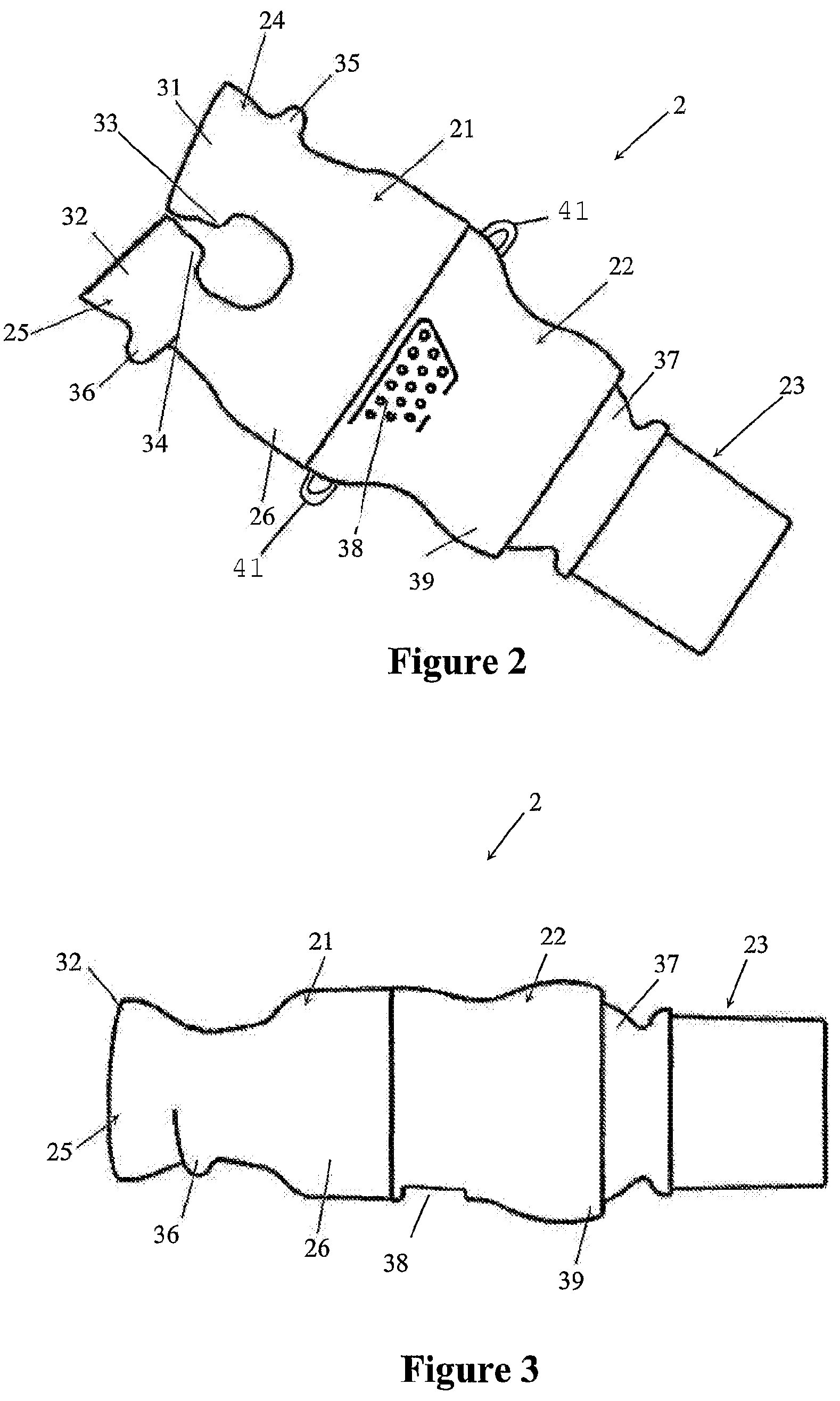
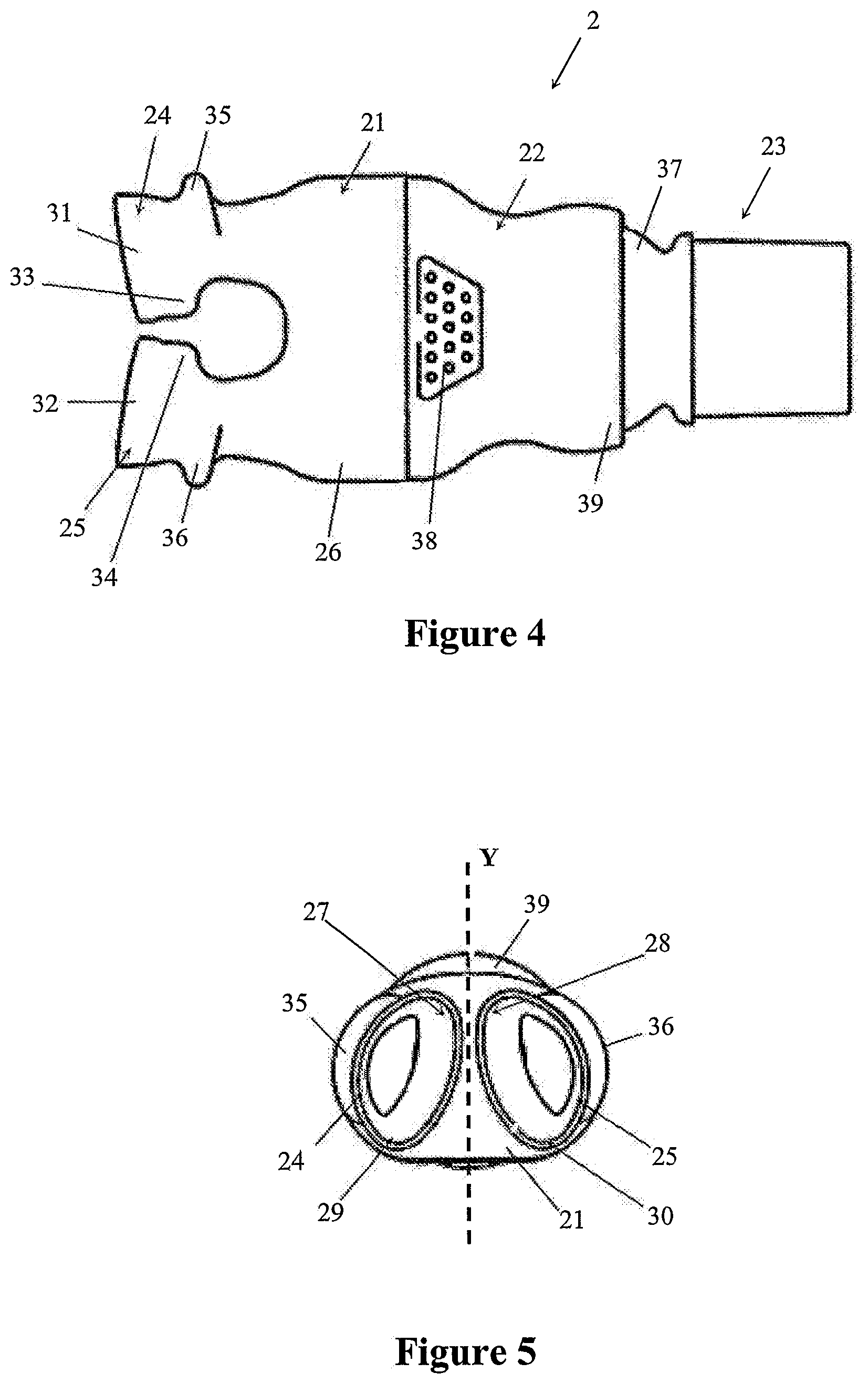
1. A mask assembly for delivering positive airway pressure to a user in use, the mask assembly comprising: a seal member comprising a distal end with a first opening and a proximal end with at least a second opening, the first opening configured to receive pressurized gases, and the proximal end configured to seal against a user in use and provide the pressurized gases to the user; a body part comprising a connector end, a seal member end in fluid communication with the first opening of the seal member, and an inspiratory gas passage with an inspiratory gas inlet and an inspiratory gas outlet, the inspiratory gas inlet comprising an inner partially spherical socket disposed at the connector end of the body part, the inspiratory gas outlet having a height and a width, the width being greater than the height; and an angled connector comprising a partially spherical end in fluid communication with a swivelable end, wherein the partially spherical end slots into the connector end of the body part and allows rotation between the angled connector and the body part, and wherein the swivelable end is configured to connect to an inspiratory conduit configured to deliver a pressurized flow of gases into the partially spherical connector.
2. The mask assembly of claim 1, wherein the connector end comprises a round opening to the inner partially spherical socket.
3. The mask assembly of claim 1, wherein the seal member end comprises at least one circumferential extension connected to the first opening of the seal member.
4. The mask assembly of claim 1, wherein the angled connector defines a connector gas passage extending between the partially spherical end and the swivelable end.
5. The mask assembly of claim 1, wherein the partially spherical end slots into the inner partially spherical socket of the body part forming a ball jointed connection.
6. The mask assembly of claim 1, wherein the inner partially spherical socket comprises a first diameter, and wherein the height of the inspiratory gas outlet is less than the first diameter.
7. The mask assembly of claim 1, wherein the inspiratory gas outlet comprises an upper edge, a lower edge, and a height defined by a first distance between the upper and lower edges, the inspiratory gas outlet further comprising a left edge, a right edge and a width defined by a second distance between the left and right edges.
8. The mask assembly of claim 1, the body part further comprising: first and second curved lateral sides, the inspiratory gas outlet having a first height at a location between the first and second curved lateral sides; a first headgear extension having a distal end, the distal end of the first headgear extension connected to the body part at the first curved lateral side, the distal end of the first headgear extension having a second height smaller than the first height; a second headgear extension having a distal end, the distal end of the second headgear extension connected to the second curved lateral side, the distal end of the second headgear extension having a third height smaller than the first height; a headgear strap connected to the first and second headgear extensions and configured to support the mask assembly against a user's face in use.
9. The mask assembly of claim 1, wherein the seal member comprises a flexible portion formed of a flexible material, the mask assembly additionally comprising a first headgear extension having a distal end on a distal side of the flexible portion at a location spaced from a user in use, and a proximal end disposed proximally toward a left side of a user's face in use, and a second headgear extension having a distal end on the distal side of the seal member at a location spaced from a user in use, and a proximal end disposed proximally toward a right side of a user's face in use.
10. The mask assembly of claim 9 wherein, the first headgear extension comprises a first portion and a second portion, the first portion of the first headgear extension comprising the distal end of the first headgear extension and extending at least along a first lateral direction extending laterally away from and beyond an outer periphery of the seal member, the second portion of the first headgear extension extending from the first portion, along a second direction extending more proximally toward the user than the first direction in use, the second headgear extension comprising a first portion and a second portion, the first portion of the second headgear extension comprising the distal end of the second headgear extension and extending at least along a third lateral direction extending laterally away from and beyond the outer periphery of the seal member, the second portion of the second headgear extension extending from the first portion, along a fourth direction extending more proximally toward the user than the third direction in use.
11. A mask assembly for delivering positive airway pressure to a user in use, the mask assembly comprising: a seal assembly comprising a seal assembly inlet and a seal assembly outlet, the seal assembly inlet configured to receive pressurized gases, and the seal assembly outlet configured to seal against a user in use and provide pressurized gases to the user; a body part comprising a distal end and a proximal end, an inspiratory gas passage, an expiratory gas passage, and a gas passage shield disposed between the inspiratory gas passage and the expiratory gas passage, the inspiratory gas passage comprising an inspiratory gas inlet comprising an inner partially spherical socket at the distal end and an inspiratory gas outlet at the proximal end fluidically communicating with the seal assembly inlet, the gas passage shield extending along at least one side of the inspiratory gas outlet, the inspiratory gas outlet having a height and a width, the width being greater than the height; and a partially spherical connector comprising a partially spherical end with a connector outlet and a swivelable end with a connector inlet, the partially spherical end comprising a partially spherical outer surface disposed within the inner partially spherical socket, and wherein the swivelable end is configured to connect to an inspiratory conduit configured to deliver pressurized gases into the partially spherical connector.
12. The mask assembly of claim 11 additionally comprising a bias flow outlet vent disposed on the body part configured to vent expiratory gas from the expiratory gas passage to an exterior of the body part.
13. The mask assembly of claim 12, wherein the bias flow outlet vent comprises a plurality of vent holes.
14. The mask assembly of claim 12, wherein a distal end of the gas passage shield is disposed between the bias flow outlet vent and the inner partially spherical socket.
15. The mask assembly of claim 11, wherein the gas passage shield curves inwardly into the inspiratory gas passage.
16. The mask assembly of claim 11, wherein the gas passage shield defines a constriction of the inspiratory gas passage.
17. The mask assembly of claim 11 wherein the distal end of the body part comprises a round opening and the inspiratory gas passage transitions from the round opening to the inspiratory gas outlet.
18. The mask assembly of claim 11, wherein the inner partially spherical socket comprises an inner partially spherical socket surface with a diameter, the height of the inspiratory gas outlet being less than the diameter.
19. The mask assembly of claim 11, wherein the seal assembly comprises a flexible portion formed of a flexible material, the mask assembly additionally comprising a first headgear extension having a distal end on a distal side of the flexible portion at a location spaced from a user in use, and a proximal end disposed proximally toward a left side of a user's face in use, and a second headgear extension having a distal end on the distal side of the prong part at a location spaced from a user in use, and a proximal end disposed proximally toward a right side of a user's face in use.
20. The mask assembly of claim 19 wherein, the first headgear extension comprises a first portion and a second portion, the first portion of the first headgear extension comprising the distal end of the first headgear extension and extending at least along a first lateral direction extending laterally away from and beyond an outer periphery of the seal assembly, the second portion of the first headgear extension extending from the first portion, along a second direction extending more proximally toward the user than the first direction in use, the second headgear extension comprising a first portion and a second portion, the first portion of the second headgear extension comprising the distal end of the second headgear extension and extending at least along a third lateral direction extending laterally away from and beyond the outer periphery of the seal assembly, the second portion of the second headgear extension extending from the first portion, along a fourth direction extending more proximally toward the user than the third direction in use.
Description
INCORPORATION BY REFERENCE TO ANY PRIORITY APPLICATIONS
Any and all applications for which a foreign or domestic priority claim is identified in the Application Data Sheet as filed with the present application are hereby incorporated by reference and made a part of the present disclosure.
BACKGROUND
Field
The present invention relates to apparatus for treating sleep apnea. More specifically, the present invention provides a nasal positive airway pressure device.
Description of Related Art
Obstructive Sleep Apnea (OSA) is a sleep disorder that affects up to at least 5% of the population in which muscles that normally hold the airway open relax and ultimately collapse, sealing the airway. The sleep pattern of an OSA sufferer is characterised by repeated sequences of snoring, breathing difficulty, lack of breathing, waking with a start and then returning to sleep. Often the sufferer is unaware of this pattern occurring. Sufferers of OSA usually experience daytime drowsiness and irritability due to a lack of good continuous sleep.
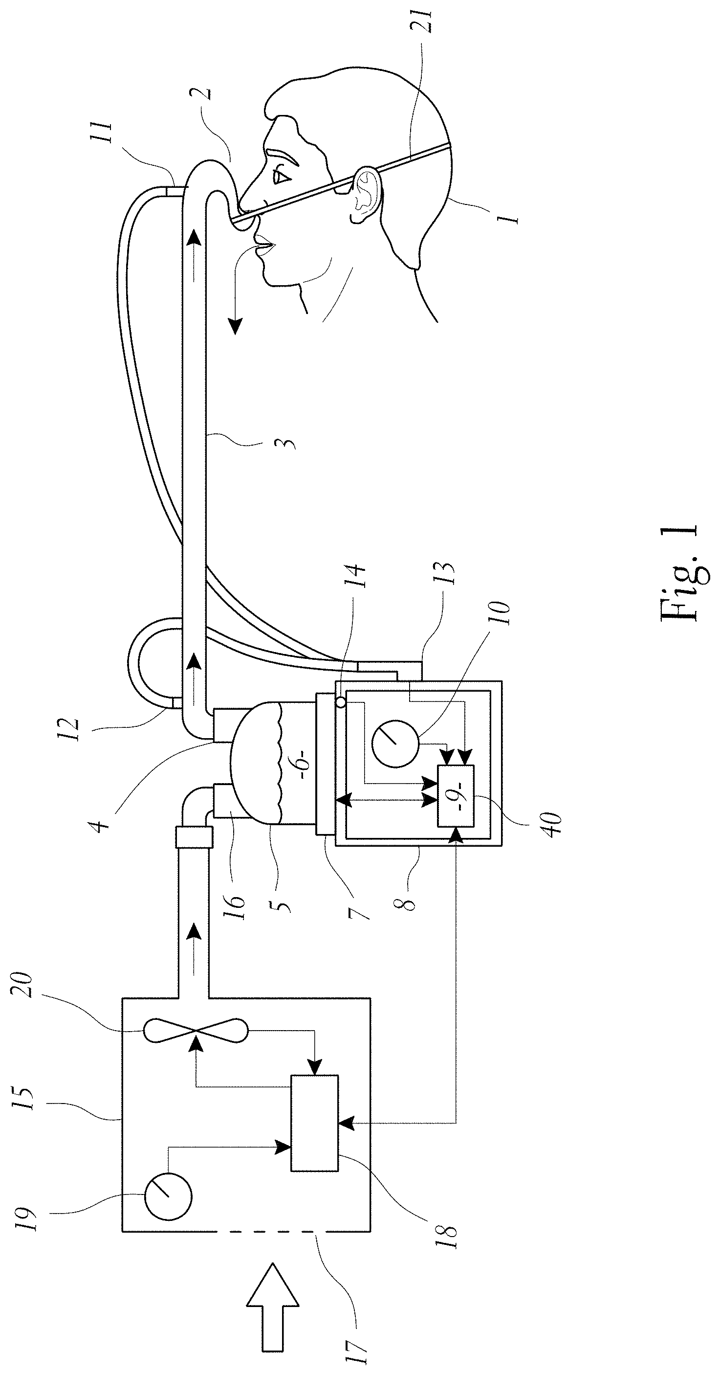
In an effort to treat OSA sufferers, a technique known as Continuous Positive Airway Pressure (CPAP) was devised. A CPAP device consists of a gases supply (or blower) with a conduit connected to supply pressurised gases to a patient, usually through a nasal mask. The pressurised air supplied to the patient effectively assists the muscles to keep the patient's airway open, eliminating the typical OSA sleep pattern.
The procedure for administering CPAP treatment has been well documented in both the technical and patent literature. Briefly stated, CPAP treatment acts as a pneumatic splint of the airway by the provision of a positive pressure, usually in the range 4 to 20 cm Hsub2O. The air is supplied to the airway by a motor driven blower whose outlet passes via an air delivery hose to a nose (or nose and/or mouth) mask sealingly engaged to a patient's face by means of a harness or other headgear. An exhaust port is provided in the delivery tube proximate to the mask. More sophisticated forms of positive airway pressure devices, such as bi-level devices and auto-titrating devices, are described in U.S. Pat. No. 5,148,802 of Respironics, Inc. and U.S. Pat. No. 5,245,995 of Rescare Limited, respectively.
U.S. Pat. No. 5,477,852 of Airways Ltd, Inc. discloses a nasal positive airway pressure device that has a pair of nasal members each having a cannula tip to be inserted into the nares of the patient. Each cannula is tapered from a substantially circular cross-section outside the patient's nostril to a substantially oval cross-section at the tip inserted into the nostril. An inflatable cuff surrounds each cannula with the interior space of the cuff communicating with the lumen of the cannula through at least one aperture in the sidewall of the cannula. The nasal members are connected to one or more flexible hoses that, in turn, are connected to a source of positive air pressure. In use, positive air pressure is supplied to each cannula tip through the air hoses and nasal members. The positive air pressure inflates the cuffs to hold the nasal members in place and to effect treatment. The nasal device of U.S. Pat. No. 5,477,852 is attached to headgear that is located about a patient's head; this headgear could be considered by many patients as cumbersome and uncomfortable.
Conventional nasal masks used for administrating CPAP treatment are also considered uncomfortable and cumbersome, and prior art nasal masks and the like are noisy (due to air leaks). These disadvantages in many cases are a formidable obstacle to patient acceptance of such treatment. Therefore, a substantial number of patients either cannot tolerate treatment or choose to forego treatment. It is believed a substantial number of such patients could benefit from a nasal positive airway pressure apparatus that is more convenient to use and comfortable to wear, thereby resulting in increased treatment compliance.
As oxygen is supplied as a dry gas it is well known in the art to either heat and/or humidify gases before delivering them for breathing by a patient. In particular when delivering oxygen, or oxygen or air mixture, it has proven beneficial to humidify the gases first. In WO01/41854 of Vapotherm, Inc. a system is disclosed that allows the delivery of humidified oxygen through a nasal cannula. This system uses a narrow bore conduit and nasal cannula with a high resistance to gas flows, thereby requiring the oxygen be of a high pressure. Air, as well as oxygen can also be passed down the conduit and nasal cannula and it too must be of a high pressure. This system allows the delivery of high flows of oxygen enriched air to the patient, but is limited in the flows achievable due to the narrow bore of the cannula resulting in high resistance gas flow and excessive velocity and noise upon exiting the cannula. Furthermore, the narrowness of the nasal cannula in this system allows easy expiration of gases between the prongs and nares and therefore does not create any positive airway pressure.
Innomed Technologies, Inc. manufactures a nasal cannula device called the NASALAIRE.TM.. In this device air or oxygen travels down a wide bore conduit to nasal cannula. The NASALAIRE.TM. creates a physical seal between the nares and itself, and relies on the absence of leaks around itself and the nares to deliver pressure supplied by a continuous positive airway pressure (CPAP) blower to the airway of the wearer.
SUMMARY
It is an object of the present invention to provide a breathing assistance apparatus which goes someway to overcoming the above mentioned disadvantages or which will at least provide the public a useful choice.
Accordingly in a first aspect the present invention consists in a breathing assistance apparatus comprising:
nasal cannula, shaped to fit within a user's nares, and adapted to deliver said humidified gases to said user,
a pressurised source of gases,
transportation means adapted to, in use, be in fluid communication with said source of gases and said nasal cannula and adapted to in use convey said gases to said user,
wherein said nasal cannula including at least one prong allowing high flow delivery of said humidified gases and creating a positive airway pressure in said patient's airway, said at least one prong having an angled end, such that in use, gases flowing through said prong are directed to said user's nasal passages.
In a second aspect the present invention consists in a breathing assistance apparatus comprising:
nasal cannula, shaped to fit within a user's nares,
a pressurised source of gases,
transportation means adapted to, in use, be in fluid communication with said source of gases and said nasal cannula and adapted to in use convey said gases to said user,
wherein said nasal cannula are adapted to deliver said humidified gases to said user, said nasal cannula including at least one prong allowing high flow delivery of said humidified gases and creating positive airway pressure in said patient's airway, said at least one prong having an end that is flared outwardly.
To those skilled in the art to which the invention relates, many changes in construction and widely differing embodiments and applications of the invention will suggest themselves without departing from the scope of the invention as defined in the appended claims. The disclosures and the descriptions herein are purely illustrative and are not intended to be in any sense limiting.
BRIEF DESCRIPTION OF THE DRAWINGS
Preferred forms of the present invention will now be described with reference to the accompanying drawings.
FIG. 1 is a block diagram of a system providing humidified continuous positive airway pressure to a user as might be used in conjunction with a nasal cannula of the present invention.
FIG. 2 is a perspective view of a first embodiment of the nasal cannula of the present invention.
FIG. 3 is a side view of the nasal cannula of FIG. 2.
FIG. 4 is a plan view of the nasal cannula of FIG. 2.
FIG. 5 is a prong end view of the nasal cannula of FIG. 2
FIG. 6 is an exploded view of the nasal cannula of FIG. 2.
FIG. 7 is a side view of a second embodiment of a nasal cannula of the present invention.
FIG. 8 is a side view of a third embodiment of a nasal cannula of the present invention.
FIG. 9 is a perspective view of a fourth embodiment of a nasal cannula of the present invention.
FIG. 10 is a side view of the nasal cannula of FIG. 9.
FIG. 11 is an exploded perspective view of the nasal cannula of FIG. 9.
FIG. 12 is a front view of the prongs of the nasal cannula of FIG. 9.
FIG. 13 is an exploded side view of the nasal cannula of FIG. 9.
FIG. 14 is a side cross-sectional view of a fifth embodiment of the nasal cannula of the present invention where the connection between a body part and connector of the cannula includes a plurality of channels.
FIG. 15 is a cross-section through AA of the nasal cannula of FIG. 14.
FIG. 16 is a side cross-sectional view of a sixth embodiment of the nasal cannula of the present invention including a shield that protects an outlet vent from inlet gases.
FIG. 17 is a cross-section through BB of the nasal cannula of FIG. 16.
DETAILED DESCRIPTION
Whether used in a hospital environment or in a home environment, the nasal cannula of the present invention will generally have associated three main pieces of apparatus. Firstly, an active humidifier, which that controls the temperature of a heater plate heating a body of water to achieve a desired temperature and humidity of the gases being humidified. Secondly, a transport conduit from the humidifier to the patient is also required, which is preferably heated to reduce condensation, or "rain out". Thirdly, a cannula designed to fit into the nasal cavity and deliver humidified, pressurized gases. In particular, in one embodiment the nasal cannula of the present invention has two flared end prongs that seal within a patient's nares, although in some embodiments the cannula may have a single prong. The cannula prongs are shaped such that a step is created between them so that the prongs abut the user's nasal septum in use. Furthermore, the gripping action of the sides of the prongs to the user's septum in use prevents the prongs from dislodging from the user's nares. In another embodiment the prongs of the nasal cannula are angled toward one another as well as having an angled profile at the outlet of gases, such that gases flow from the prongs flows back into the nasal passage and is not forced up into the rest of the nasal cavity.
With reference to FIG. 1 a humidified Continuous Positive Airway Pressure (CPAP) system is shown in which a patient 1 is receiving humidified and pressurised gases through the nasal cannula 2 of the present invention. The cannula 2 is connected to a humidified gases transportation pathway or inspiratory conduit 3. It should be understood that delivery systems could also be VPAP (Variable Positive Airway Pressure) and BiPAP (Bi-level Positive Airway Pressure) or numerous other forms of respiratory therapy. Inspiratory conduit 3 is connected to the outlet 4 of a humidification chamber 5 that contains a volume of water 6. The inspiratory conduit 3 may contain heating means or heater wires (not shown) which heat the walls of the conduit to reduce condensation of humidified gases within the conduit. The humidification chamber 6 is preferably formed from a plastics material and may have a highly heat conductive base (for example an aluminium base) which is in direct contact with a heater plate 7 of humidifier 8. The humidifier 8 is provided with control means or electronic controller 9 that may comprise a microprocessor based controller executing computer software commands stored in associated memory.
The controller 9 receives input from sources such as user input means or dial 10 through which a user of the device may, for example, set a predetermined required value (preset value) of humidity or temperature of the gases supplied to patient 1. The controller may also receive input from other sources; for example, temperature and/or flow velocity sensors 11 and 12 through connector 13 and heater plate temperature sensor 14. In response to the user set humidity or temperature value input via dial 10 and the other inputs, controller 9 determines when (or to what level) to energise heater plate 7 to heat the water 6 within humidification chamber 5. A flow of gases (for example air) is provided to the chamber through inlet 16 from a gases supply means or blower 15. As the volume of water 6 within humidification chamber 5 is heated, water vapour begins to fill the volume of the chamber above the water's surface and is passed out of the humidification chamber 5 through outlet 4. Exhaled gases from the patient's mouth are passed directly to ambient surroundings in FIG. 1.
The blower 15 is provided with variable pressure regulating means or a variable speed fan 20 which draws air or other gases through the blower inlet 17. The speed of the variable speed fan 20 is controlled by the electronic controller 18 (or alternatively the function of the controller 18 could carried out by the controller 9) in response to inputs from the controller 9 and a user set predetermined required value (preset value) of pressure or fan speed via the dial 19.
Flared Prong Nasal Cannula
A first embodiment of a nasal cannula of the present invention is shown in detail in FIGS. 2 to 6. Referring to FIGS. 2 and 6, the nasal cannula 2 comprises three main components; the prong part 21, body part 22 and ball connector 23.
The prong part 21 has two nasal prongs 24, 25, each of which are substantially shaped to follow the contours of the human nares and in use are placed inside a user's nares. The prongs 24, 25 extend out from a hollow tubular body 26 that in use fits to the body part 22. Each of the prongs 24, 25 are integrally moulded with the tubular body 26 in a flexible plastics material or rubber, such as silicone, other thermoset elastomers or thermoplastic elastomers such as Kraton.TM.. The prongs 24, 25 are substantially oval tubular members that allow for a passage of gases. In particular, as shown in FIG. 5, the prongs are oval in shape and angled in the same manner as a human's nares. The prongs 24, 25 are angled toward one another (or toward the vertical axis Y) at the top 27, 28 of the prongs and away from one another at the bottom 29, 30 of the prongs. Furthermore, the ends 31, 32 of the prongs flare outwardly and preferably are formed such that the ends of the prongs are thinner in cross-section than the rest of the prongs. The flared thinner section ends 31, 32 of the prongs assist with the sealing of the prongs 24, 25 in use within the user's nares. When in use and with gases flowing through the prongs the force of the gas pressure will force the prong ends 31, 32 to flare outwardly and seal against the inside of the user's nares.
The prongs 24, 25 each include a step 33, 34 formed along their lengths. Each of the steps 33, 34 are formed on the prongs 24, 25 in an opposing manner such that in use, when the prongs are within a user's nares the steps 33, 34 abut the user's nasal septum and form a ledge that prevents dislodgement of the prongs. The prongs 24, 25 also have protrusions 35, 36 formed on their outer edges that abut the sides of the user's nares (opposite to the nasal septum). The protrusions 35, 36 assist in preventing the dislodgement of the prongs, especially if the user moves his or her head. The protrusions 35, 36 also maintain the prongs within the user's nares in a correct orientation such that in use gases flow through the prongs and directly up the user's nasal passages.
The body part 22 is a tubular passageway in which the prong part 21 is connected at one end and a ball joint 37 at the other end. The ball joint 37 extends from the connector 23 and slots into a complementary shaped (partial sphere) socket end 39. The body part 22 also has a number of apertures 38 formed in it, which act as a bias flow outlet vent. Therefore, any gases exhaled by the user through their nose will exit through the apertures 38.
The connector 23 is preferably connected to the inspiratory conduit 3 (see FIG. 1) that supplies gases flow to the cannula 2. The inspiratory conduit 3 may be moulded directly to the connector 23 or other connection mechanisms may be used, such as a friction fit formed between the connector and conduit.
Although a ball and socket joint, as described above, between the body part 22 and connector 23 is preferred other connections may be utilised, such as a flexible piece of silicone, or other appropriate connection. The connection between the cannula body and connector must be able to be flexed or rotated to allow for the inspiratory conduit 3 to be moved without causing the dislodgement of the nasal cannula 2 from the user's nares.
In the preferred form of the nasal cannula 2 of the present invention the body part 22 and connector 23 are preferably made from a hard or rigid plastics material, such as polypropylene, polycarbonate or acetyl. In other forms the body part 22 and connector 23 may be of different plastics materials to allow for increased slidability between these parts.
The prong part 21 may be supplied in various different sizes such that different sized user's may remove an existing prong part and simply attach a different sized flexible plastics prong part over the body part 22.
To provide additional comfort for the user or ensure the nasal cannula of the present invention do not fall from a user's nares, the nasal cannula may be used in combination with a headgear strap, which in one embodiment is a small flexible tube. For example, FIG. 1 shows a headgear strap 40 extending from the nasal cannula 2. The ends of the headgear strap that attach to the cannula may attach to extensions (or loops) 41 on the body part 22 of the cannula shown in FIG. 2, or may attach about other appropriate areas of the cannula, for example, about the connector 23.
The abovementioned embodiment of the nasal cannula 2 of the present invention is preferably a wide bore pronged cannula used for high flow conditions.
A second embodiment of the present invention is shown in FIG. 7. In this embodiment of the nasal cannula 42 the prongs 43, 44 are preferably small bore prongs for use with lower flow conditions. The prongs 43, 44 are similarly shaped to the prongs 24, 25 detailed above, but may not seal in the same manner as the abovementioned prongs due to the smaller size of the prongs. In fact these prongs may not seal at all in use within the user's nares.
Furthermore, in this second embodiment the nasal cannula 42 is smaller and weighs less as it is only comprised of a prong body 45 and prongs 43, 44, where the body 45 is connected to a small tube that is formed with corrugations or bellows 48 that connect to an inspiratory tube or conduit 47 (similar to the inspiratory conduit 3 described above) that receives a supply of gases.
The corrugations of bellows 48 will bend or move when a weight or force is placed on the cannula, thereby preventing dislodgement of the cannula 42 from a user's face in use. In particular, the corrugations or bellows 48 prevent transferral of the torque onto the cannula 42 when a user moves his or her head.
The body 45 of the cannula 42 is provided with a number of apertures 46 that allows for gases exhaled by the users to be expelled into the ambient air.
The prong body and prongs of this embodiment of the cannula of the present invention are preferably formed a flexible plastics material or rubber, such as silicone, other thermoset elastomers or thermoplastic elastomers such as Kraton.TM..
A third embodiment of the nasal cannula of the present invention is shown in FIG. 8 where the cannula may be provided with corrugated or baffled sections on the prongs. The nasal cannula 49 of this embodiment is similar to that of FIG. 2 but the prongs 50, 51 have a series of corrugations 52, 53 formed in them. The corrugations 52, 53 allow for movement of each of the prongs 50, 51 for a better user fit, and allow for movement of the cannula 49 without causing dislodgement of the prongs from the user's nares.
Angled Prong Nasal Cannula
A fourth embodiment of the nasal cannula of the present invention is shown in FIGS. 9 to 13. The nasal cannula 60 has a similar construction to the nasal cannula of FIG. 2 and comprises three main components; a prong part 61, body part 62 and ball jointed connector 63.
The prong part 61 preferably has two nasal prongs 64, 65, each of which are substantially shaped to follow the contours of the human nares and in use are placed inside a user's nares. In some forms a cannula with only one prong may be provided. The prongs 64, 65 extend out from a hollow tubular body 66 that in use fits to the body part 62, preferably about an extension 67 (as shown in the exploded view of the nasal cannula of FIG. 11). Each of the prongs 64, 65 are integrally moulded with the tubular body 66 in a flexible plastics material or rubber, such as silicone, other thermoset elastomers or thermoplastic elastomers, such as Kraton.TM.. The prongs 64, 65 are substantially oval tubular members that allow for a passage of gases.
In particular, as shown in FIG. 12, the prongs are oval in shape (to reflect the shape of human nares) and angled in the same manner as a human's nares. The prongs 64, 65 are angled toward one another (or toward the horizontal axis X) such that angles a are formed between the midlines m, n through each respective prong 64, 65. The angled profile of the prongs 64, 65 means that they are more ergonomically correct with a human's nares and may assist in directing the gases flow from the prongs to the user's nasal cavities. The prongs 64, 65 are constructed such that their cross-sectional width narrows closer to the tip of each prong.
In the preferred form the prongs 64, 65 have an angled and profiled end 76 (see FIG. 10). The angled ends 76 assist in directing gases flow to the user's nasal passages.
Each of the prongs 64, 65 has a flange 73, 74 disposed about its circumference. The flanges 73, 74 are at a position on the prongs 64, 65 such that the each of the flanges rests against the outside of each of the patient's nares. The flanges 73, 74 do not extend inside the nares, but rest at the entranceway of the user's nares, and preferably seal the nares. In some users the flanges 73, 74 may extend within the user's nares and provide sealing of the nares. The flanges 73, 74 are preferably thin flexible extensions that extend substantially completely around the circumference of the prongs 64, 65. The flanges 73, 74 are preferably substantially elliptical in shape with one side (for example, side 89, which in use will abut the nasal septum of a user) of the flange extending out from each prong further than the other side of each prong. There is a recessed area 88 on each of the prongs between the flange and the shaped ends of the prongs in which preferably in use the ends of a user's nares rest.
The body part 62 is a tubular passageway in which the prong part 61 is connected at one end and a ball joint 69 at the other end. The ball joint 69 extends from the connector 63 and slots into a complementary shaped (partial sphere) socket end 70 on the body part 62. The body part 62 may also have a plurality of apertures 71 formed in it, which acts as a bias flow outlet vent. Therefore, any gases exhaled by the user through their nose will exit through the apertures 71.
A shield 75 (illustrated by the dashed line in FIG. 10) may extend over the bias vent 71 inside the body part 70 to prevent gases from the blower (gases supply 15) from interacting with the bias vent 71 and vent holes, causing noise in use.
In a sixth embodiment as shown in FIGS. 16 and 17 a nasal cannula without a prong part is shown, but that includes a shield similar to that described above. In this embodiment a body part 90 and a ball jointed connector 91 fit together as described above. The body part 90 includes an expiratory vent shield 92 that extends down from the top wall 94 of the body part 90 and shields the outlet vent 93.
Referring back to FIGS. 10 to 13, preferably the ball joint connector 63 is angled and extends into a swivelable connector 68. The swivel connector 68 is capable in use of being connected to the inspiratory conduit 3 (see FIG. 1) that supplies gases flow to the cannula 60. The inspiratory conduit 3 may be moulded directly to the connector 68 or other connection mechanisms may be used, such as a friction fit formed between the connector 68 and the conduit 3.
In other forms of the present invention the ball joint connector 63 or the ball joint 69 may have formed in it a plurality of channels. One example of this is the embodiment of FIGS. 14 and 15. Such channels allow there to be a leak when gases flow through the connector to the cannula and prongs. The channels are therefore capable of acting as a bias flow and a separate bias flow out outlet (such as that outlet 71 described above) may not be required.
In FIGS. 14 and 15 only a body part 82 and ball jointed connector 83 are shown. The body part 82 and ball jointed connector 83 join in a manner as described above, where the substantially half sphere shaped end 84 of the body part 82 receives the substantially half sphere shaped end 85 of the connector 83. The ends 84, 85 enable a rotation between the body part 82 and connector 83. In this embodiment two channels 86, 87 are formed in the connector end 85. Two channels are shown in this embodiment but there may be only one or any number of channels. Similarly, channels may be formed in the body part end 84.
It is preferred that there is a ball and socket joint, as described above, between the body part 62 and connector 63, although other connections may be utilised, such as a flexible piece of silicone, or other appropriate connection. The connection between the cannula body and connector must be able to be flexed or rotated to allow for the inspiratory conduit 3 to be moved without causing the dislodgement of the nasal cannula 60 from the user's nares.
In the preferred form of the nasal cannula 60 of the present invention the body part 62, connector 63, ball joint 69 and swivel connector 68 are preferably made from a hard or rigid plastics material, such as polypropylene, polycarbonate or acetyl. In other forms these may be of different plastics materials to allow for increased slidability between these parts.
The prong part 61 may be supplied in various different sizes such that different sized user's may remove an existing prong part and simply attach a different sized flexible plastics prong part over the body part 62.
To provide additional comfort for the user or ensure the nasal cannula of the present invention does not fall from a user's nares, the nasal cannula 60 is preferably used in combination with a headgear strap. The strap may be similar to that shown in FIG. 1 with relation to the first form of the nasal cannula 2. In this fourth form of the nasal cannula 60 the body part 62 has headgear extensions 72, 73 that extend out from the body part 70. The extensions 72, 73 each have a channel 77, 78 formed in them that is capable of receiving an end 80, 81 of the headgear strap 79. The strap ends 80, 81 in use are threaded through apertures (preferably two) and extend into and are held in the channels 77, 78. In this form the headgear strap 79 is made from a small diameter silicon, rubber or similar type material. Therefore, when the strap ends 80, 81 are threaded through the apertures friction is created that maintains the straps within the apertures and prevents the straps from slipping from the cannula.
In other forms the ends of the headgear strap that attach to the cannula may attach to extensions (or loops) 41 on the body part 22 of the cannula shown in FIG. 6, or may attach about other appropriate areas of the cannula, for example, about the connector 23.
* * * * *
References
-
resmed.com/en-us/products/masks/mirage_swift_II_nasal_pillows._system/Mirage-Swift-II-Nasal-Pillows-System.html?menu=products
-
-
-
-
-
-
-
-
-
resmcd.com/en-us/assets/documents/product/swift-It/clinical_fact_sheet/1012406swiftIt_fact-sheet_usa_eng.pdf
-
-
-
puritanbennett.com/prod/product.aspx?id=233
-
-
puritanbennett.com/_Catalog/PDF/Product/BreezeSleepGear.pdf
-
-
-
optilife.respironics.com:80
-
-
opti1ife.respironics.com:80/features.aspx
-
-
youtube.com/watch?v=shjcNmvvcBA
-
homedepot.com/p/Everbilt-1-2-in-Galvanized-HexNut-804076/20464-7893
-
cpapxchange.com/cpap-machines-biap-machines/system-one-60-seri-es-cpap-humidifier-manual.pdffrontcover
-
-
resmed.com-/maskframes/mask.htm
-
weddingbands.com/ProductPop-wedding-bands-metal/48214W.html
D00000
D00001
D00002
D00003
D00004
D00005
D00006
D00007
D00008
D00009
D00010
XML
uspto.report is an independent third-party trademark research tool that is not affiliated, endorsed, or sponsored by the United States Patent and Trademark Office (USPTO) or any other governmental organization. The information provided by uspto.report is based on publicly available data at the time of writing and is intended for informational purposes only.
While we strive to provide accurate and up-to-date information, we do not guarantee the accuracy, completeness, reliability, or suitability of the information displayed on this site. The use of this site is at your own risk. Any reliance you place on such information is therefore strictly at your own risk.
All official trademark data, including owner information, should be verified by visiting the official USPTO website at www.uspto.gov. This site is not intended to replace professional legal advice and should not be used as a substitute for consulting with a legal professional who is knowledgeable about trademark law.