Breathing assistance apparatus
McAuley , et al.
U.S. patent number 10,272,218 [Application Number 14/977,083] was granted by the patent office on 2019-04-30 for breathing assistance apparatus. This patent grant is currently assigned to Fisher & Paykel Healthcare Limited. The grantee listed for this patent is Fisher & Paykel Healthcare Limited. Invention is credited to Alastair Edwin McAuley, Gregory James Olsen, Roheet Patel.


View All Diagrams
| United States Patent | 10,272,218 |
| McAuley , et al. | April 30, 2019 |
Breathing assistance apparatus
Abstract
A mask assembly for use as part of an apparatus for supplying a flow of respiratory gases to a user is disclosed. The mask assembly includes a mask body having an inlet through which said flow of respiratory gases are provided to the interior of said mask body. A mask seal assembly comprising a seal of flexible material and a clip of rigid material is attached to the body. The seal has a first side and a second side. The first side of the seal is shaped to approximately match the contours of a user's face and in use substantially seal against a user's face. The second side is attached to the clip. The clip provides an interface extending substantially the full perimeter or periphery of the mask seal assembly for releasably attaching the mask seal assembly to the mask body. The clip comprises a bridging portion spanning outwards from the perimeter or periphery of the mask body to space at least a portion of the second side of the seal outwards from the perimeter or periphery of the mask body.
| Inventors: | McAuley; Alastair Edwin (Auckland, NZ), Olsen; Gregory James (Auckland, NZ), Patel; Roheet (Auckland, NZ) | ||||||||||
|---|---|---|---|---|---|---|---|---|---|---|---|
| Applicant: |
|
||||||||||
| Assignee: | Fisher & Paykel Healthcare
Limited (Auckland, NZ) |
||||||||||
| Family ID: | 45927943 | ||||||||||
| Appl. No.: | 14/977,083 | ||||||||||
| Filed: | December 21, 2015 |
Prior Publication Data
| Document Identifier | Publication Date | |
|---|---|---|
| US 20160106944 A1 | Apr 21, 2016 | |
Related U.S. Patent Documents
| Application Number | Filing Date | Patent Number | Issue Date | ||
|---|---|---|---|---|---|
| 13877903 | |||||
| PCT/NZ2011/000211 | Oct 7, 2011 | ||||
| 61391527 | Oct 8, 2010 | ||||
| Current U.S. Class: | 1/1 |
| Current CPC Class: | A61M 16/0683 (20130101); A61M 16/0633 (20140204); A61M 16/0622 (20140204); A61M 16/0066 (20130101); A61M 16/0616 (20140204); A61M 2205/3368 (20130101); A61M 16/109 (20140204); A61M 16/16 (20130101); A61M 2016/0039 (20130101); A61M 16/024 (20170801); A61M 2205/50 (20130101); A61M 16/0069 (20140204) |
| Current International Class: | A61M 16/06 (20060101); A61M 16/10 (20060101); A61M 16/00 (20060101); A61M 16/16 (20060101) |
| Field of Search: | ;128/203.29,205.25,206.12,206.16,206.21,206.28 ;2/182.2-182.7 |
References Cited [Referenced By]
U.S. Patent Documents
| 301111 | July 1884 | Genese |
| 472238 | April 1892 | Van Orden |
| 577926 | March 1897 | Miller |
| 718470 | January 1903 | Jones |
| 751091 | February 1904 | Moran |
| 770013 | September 1904 | Linn |
| 1635545 | July 1927 | Drager |
| 2126755 | August 1938 | Dreyfus |
| 2228218 | January 1941 | Schwartz |
| 2241535 | May 1941 | Boothby et al. |
| 2296150 | September 1942 | Dockson et al. |
| 2353643 | July 1944 | Bulbulian |
| 2359506 | October 1944 | Battley et al. |
| 2388604 | November 1945 | Eisenbud |
| 2452845 | November 1948 | Fisher |
| 2508050 | May 1950 | Valente |
| 2693800 | November 1954 | Caldwell |
| 2738788 | March 1956 | Matheson et al. |
| 2843121 | July 1958 | Hudson |
| 2859748 | November 1958 | Hudson |
| 2875759 | March 1959 | Galleher |
| 2939458 | June 1960 | Lundquist |
| 3424633 | January 1969 | Corrigall et al. |
| 3490452 | January 1970 | Greenfield |
| 3599635 | August 1971 | Kenneth |
| 3682171 | August 1972 | Dali et al. |
| 3834682 | September 1974 | McPhee |
| 3850171 | November 1974 | Ball et al. |
| 3894562 | July 1975 | Mosley et al. |
| 3972321 | August 1976 | Proctor |
| 3977432 | August 1976 | Vidal |
| 3992720 | November 1976 | Nicolinas |
| 4090510 | May 1978 | Segersten |
| D250047 | October 1978 | Lewis et al. |
| D250131 | October 1978 | Lewis et al. |
| 4127130 | November 1978 | Naysmith |
| 4150464 | April 1979 | Tracy |
| D252322 | July 1979 | Johnson |
| 4201205 | May 1980 | Bartholomew |
| 4258710 | March 1981 | Reber |
| 4266540 | May 1981 | Panzik et al. |
| 4278082 | July 1981 | Blackmer |
| 4354488 | October 1982 | Bartos |
| 4367735 | January 1983 | Dali |
| 4378011 | March 1983 | Warncke et al. |
| 4437462 | March 1984 | Piljay |
| 4454880 | June 1984 | Muto et al. |
| 4603602 | August 1986 | Montesi |
| 4621632 | November 1986 | Bartels et al. |
| 4644974 | February 1987 | Zingg |
| 4676241 | June 1987 | Webb et al. |
| D293613 | January 1988 | Wingler |
| 4753233 | June 1988 | Grimes |
| 4782832 | November 1988 | Trimble et al. |
| 4836200 | June 1989 | Clark et al. |
| 4856508 | August 1989 | Tayebi |
| 4915104 | April 1990 | Marcy |
| 4915105 | April 1990 | Lee |
| 4919128 | April 1990 | Kopala et al. |
| 4938209 | July 1990 | Fry |
| 4941467 | July 1990 | Takata |
| 4944310 | July 1990 | Sullivan |
| D310431 | September 1990 | Bellm |
| 4958658 | September 1990 | Zajac |
| 4971051 | November 1990 | Toffolon |
| 4986269 | January 1991 | Hakkinen |
| 5010925 | April 1991 | Atkinson et al. |
| 5016625 | May 1991 | Hsu et al. |
| 5031261 | July 1991 | Fenner |
| 5042478 | August 1991 | Kopala et al. |
| D320677 | October 1991 | Kumagai et al. |
| D321419 | November 1991 | Wallace |
| 5062421 | November 1991 | Burns et al. |
| 5065756 | November 1991 | Rapoport |
| D322318 | December 1991 | Sullivan |
| 5074297 | December 1991 | Venegas |
| 5094236 | March 1992 | Amad |
| 5113857 | May 1992 | Dickerman et al. |
| 5121745 | June 1992 | Israel et al. |
| 5148802 | September 1992 | Sanders et al. |
| 5164652 | November 1992 | Johnson et al. |
| 5231979 | August 1993 | Rose |
| 5243971 | September 1993 | Sullivan |
| 5245995 | September 1993 | Sullivan et al. |
| D340317 | October 1993 | Cole |
| 5259377 | November 1993 | Schroeder |
| 5269296 | December 1993 | Landis |
| 5315859 | May 1994 | Schommer |
| 5349949 | September 1994 | Schegerin |
| 5366805 | November 1994 | Fujiki et al. |
| D354128 | January 1995 | Rinehart |
| D355484 | February 1995 | Rinehart |
| 5400776 | March 1995 | Bartholomew |
| 5429683 | July 1995 | Le Mitouard |
| 5438979 | August 1995 | Johnson et al. |
| 5441046 | August 1995 | Starr et al. |
| 5449206 | September 1995 | Lockwood |
| 5449234 | September 1995 | Gipp et al. |
| 5458202 | October 1995 | Fellows et al. |
| 5460174 | October 1995 | Chang |
| 5477852 | December 1995 | Landis et al. |
| 5513634 | May 1996 | Jackson |
| 5518802 | May 1996 | Colvin et al. |
| 5533506 | July 1996 | Wood |
| 5542128 | August 1996 | Lomas |
| 5551419 | September 1996 | Froehlich et al. |
| 5558090 | September 1996 | James |
| 5570689 | November 1996 | Starr et al. |
| 5588423 | December 1996 | Smith |
| 5595174 | January 1997 | Gwaltney |
| 5601078 | February 1997 | Schaller et al. |
| D378610 | May 1997 | Reischel et al. |
| 5649532 | July 1997 | Griffiths |
| 5657752 | August 1997 | Landis et al. |
| 5662101 | September 1997 | Ogden et al. |
| 5664566 | September 1997 | Mcdonald et al. |
| 5687715 | November 1997 | Landis |
| 5690097 | November 1997 | Howard et al. |
| 5724965 | March 1998 | Handke et al. |
| 5752510 | May 1998 | Goldstein |
| 5755578 | May 1998 | Contant et al. |
| 5806727 | September 1998 | Joseph |
| 5746201 | December 1998 | Kidd |
| 5857460 | January 1999 | Popitz |
| 5884624 | March 1999 | Barnett et al. |
| 5904278 | May 1999 | Barlow et al. |
| 5918598 | July 1999 | Belfer |
| 5921239 | July 1999 | McCall et al. |
| 5941245 | August 1999 | Hannah et al. |
| 5943473 | August 1999 | Levine |
| 5953763 | September 1999 | Gouget |
| 5966745 | October 1999 | Schwartz et al. |
| 6016804 | January 2000 | Gleason et al. |
| 6017315 | January 2000 | Starr et al. |
| 6019101 | February 2000 | Cotner et al. |
| 6021528 | February 2000 | Jurga |
| 6039044 | March 2000 | Sullivan |
| 6050260 | April 2000 | Daniell et al. |
| 6112746 | September 2000 | Kwok et al. |
| 6116235 | September 2000 | Walters et al. |
| 6119693 | September 2000 | Kwok et al. |
| 6119694 | September 2000 | Correa et al. |
| 6135109 | October 2000 | Blasdell et al. |
| 6135432 | October 2000 | Hebblewhite et al. |
| 6192886 | February 2001 | Rudolph |
| D440302 | April 2001 | Wolfe |
| 6272933 | August 2001 | Gradon et al. |
| 6298850 | October 2001 | Argraves |
| 6302105 | October 2001 | Wickham et al. |
| 6341606 | January 2002 | Bordewick et al. |
| 6347631 | February 2002 | Hansen et al. |
| D455891 | April 2002 | Biedrzycki |
| 6398197 | June 2002 | Dickinson et al. |
| 6412488 | July 2002 | Barnett et al. |
| 6418928 | July 2002 | Bordewick et al. |
| 6427694 | August 2002 | Hecker et al. |
| 6431172 | August 2002 | Bordewick |
| 6435181 | August 2002 | Jones, Jr. et al. |
| 6439234 | August 2002 | Curti et al. |
| 6457473 | October 2002 | Brostrom et al. |
| 6467483 | October 2002 | Kopacko et al. |
| 6478026 | November 2002 | Wood |
| 6484725 | November 2002 | Chi et al. |
| 6488664 | December 2002 | Solomon et al. |
| 6491034 | December 2002 | Gunaratnam et al. |
| 6497232 | December 2002 | Fecteau et al. |
| 6513526 | February 2003 | Kwok et al. |
| 6526978 | March 2003 | Dominguez |
| 6561190 | May 2003 | Kwok |
| 6561191 | May 2003 | Kwok |
| 6581594 | June 2003 | Drew et al. |
| 6581601 | June 2003 | Ziaee |
| 6581602 | June 2003 | Kwok et al. |
| 6584977 | July 2003 | Serowski |
| 6588424 | July 2003 | Bardel |
| 6561188 | August 2003 | Ellis |
| 6615832 | September 2003 | Chen |
| 6629531 | October 2003 | Gleason et al. |
| 6631718 | October 2003 | Lovell |
| 6634358 | October 2003 | Kwok et al. |
| 6637434 | October 2003 | Noble |
| 6644315 | November 2003 | Ziaee |
| 6651658 | November 2003 | Hill et al. |
| 6651663 | November 2003 | Barnett et al. |
| 6659102 | December 2003 | Sico |
| 6662803 | December 2003 | Gradon et al. |
| 6668828 | December 2003 | Figley et al. |
| 6679257 | January 2004 | Robertson et al. |
| 6679265 | January 2004 | Strickland et al. |
| 6691707 | February 2004 | Gunaratnam et al. |
| 6712072 | March 2004 | Lang |
| 6736139 | May 2004 | Wix |
| 6772761 | August 2004 | Rucker, Jr. |
| 6796308 | September 2004 | Gunaratnam et al. |
| 6817362 | November 2004 | Gelinas et al. |
| 6823869 | November 2004 | Raje et al. |
| 6851425 | February 2005 | Jaffre et al. |
| 6883177 | April 2005 | Ouellette et al. |
| 6892729 | May 2005 | Smith et al. |
| 6895965 | May 2005 | Scarberry et al. |
| 6907882 | June 2005 | Ging et al. |
| 6918390 | July 2005 | Lithgow et al. |
| 6951218 | October 2005 | Gradon et al. |
| 6953354 | October 2005 | Edirisuriya et al. |
| 7004165 | February 2006 | Salcido |
| 7007696 | March 2006 | Palkon et al. |
| 7021311 | April 2006 | Gunaratnam et al. |
| D520140 | May 2006 | Chaggares |
| 7066179 | June 2006 | Eaton et al. |
| 7077126 | July 2006 | Kummer et al. |
| D526094 | August 2006 | Chen |
| 7096864 | August 2006 | Mayer et al. |
| D533269 | December 2006 | McAuley et al. |
| 7178525 | February 2007 | Matula, Jr. et al. |
| 7178528 | February 2007 | Lau |
| 7201169 | April 2007 | Wilkie et al. |
| 7207333 | April 2007 | Tohara |
| 7210481 | May 2007 | Lovell et al. |
| 7219669 | May 2007 | Lovell et al. |
| 7225811 | June 2007 | Ruiz et al. |
| 7255106 | August 2007 | Gallem et al. |
| 7287528 | October 2007 | Ho et al. |
| 7290546 | November 2007 | Sprinkle et al. |
| 7318437 | January 2008 | Gunaratnam et al. |
| 7353827 | April 2008 | Geist |
| 7406966 | August 2008 | Wondka et al. |
| 7448386 | November 2008 | Ho et al. |
| 7487772 | February 2009 | Ging et al. |
| 7523754 | April 2009 | Lithgow et al. |
| D595841 | July 2009 | McAuley et al. |
| 7597100 | October 2009 | Ging et al. |
| 7665464 | February 2010 | Kopacko et al. |
| 7681575 | March 2010 | Wixey et al. |
| 7694677 | April 2010 | Tang |
| 7753051 | July 2010 | Burrow et al. |
| 7814911 | October 2010 | Bordewick et al. |
| 7827990 | November 2010 | Melidis et al. |
| 7877817 | February 2011 | Ho |
| 7896003 | March 2011 | Matula et al. |
| 7931024 | April 2011 | Ho et al. |
| 7934501 | May 2011 | Fu et al. |
| 8042539 | October 2011 | Chandran et al. |
| 8136524 | March 2012 | Ging et al. |
| 8136525 | March 2012 | Lubke et al. |
| D661796 | June 2012 | Andrews et al. |
| 8371302 | February 2013 | Ging et al. |
| 8397727 | March 2013 | Ng et al. |
| 8443807 | May 2013 | McAuley et al. |
| D686313 | July 2013 | Matula et al. |
| 8479726 | July 2013 | McAuley |
| 8479741 | July 2013 | McAuley et al. |
| 8567404 | October 2013 | Davidson et al. |
| 8631793 | January 2014 | Omura et al. |
| 8631799 | January 2014 | Davenport |
| 8636005 | January 2014 | Gradon et al. |
| 8701667 | April 2014 | Ho et al. |
| 8714157 | May 2014 | McAuley et al. |
| 8720444 | May 2014 | Chang |
| 8757157 | June 2014 | Price et al. |
| 8783257 | July 2014 | McAuley et al. |
| 8869797 | October 2014 | Davidson et al. |
| 8869798 | October 2014 | Wells et al. |
| 8944061 | February 2015 | D'souza et al. |
| 8950404 | February 2015 | Formica et al. |
| 8960196 | February 2015 | Henry |
| 9010331 | April 2015 | Lang et al. |
| 9027556 | May 2015 | Ng et al. |
| 9032955 | May 2015 | Lubke et al. |
| 9032956 | May 2015 | Scheiner et al. |
| 9072852 | July 2015 | McAuley et al. |
| 9119929 | September 2015 | McAuley et al. |
| 9119931 | September 2015 | D'Souza et al. |
| 9138555 | September 2015 | McAuley et al. |
| 9149596 | October 2015 | Valcic et al. |
| 9242062 | January 2016 | Melidis et al. |
| 9292799 | March 2016 | McAuley et al. |
| 9295799 | March 2016 | McAuley et al. |
| 9302065 | April 2016 | Smith et al. |
| 9320566 | April 2016 | Alston, Jr. |
| 9320866 | April 2016 | McAuley et al. |
| 9333315 | May 2016 | McAuley et al. |
| 9339622 | May 2016 | McAuley et al. |
| 9339624 | May 2016 | McAuley |
| 9375545 | June 2016 | Darkin et al. |
| 9381316 | July 2016 | Ng et al. |
| 9439405 | September 2016 | Bruggemann et al. |
| 9457162 | October 2016 | Ging et al. |
| 9486601 | November 2016 | Stallard et al. |
| 9517317 | December 2016 | McAuley et al. |
| 9522246 | December 2016 | Frater et al. |
| 9539405 | January 2017 | McAuley et al. |
| 9550038 | January 2017 | McAuley et al. |
| 9561338 | February 2017 | McAuley et al. |
| 9561339 | February 2017 | McAuley et al. |
| 9744385 | August 2017 | Henry et al. |
| 9884160 | February 2018 | McAuley et al. |
| 10080856 | September 2018 | McLaren et al. |
| 2001/0017134 | August 2001 | Bahr |
| 2001/0020474 | September 2001 | Hecker et al. |
| 2001/0029952 | October 2001 | Curran |
| 2002/0014241 | February 2002 | Gradon et al. |
| 2002/0020416 | February 2002 | Namey |
| 2002/0026934 | March 2002 | Lithgow et al. |
| 2002/0029780 | March 2002 | Frater et al. |
| 2002/0046755 | April 2002 | Voss |
| 2002/0053347 | May 2002 | Ziaee |
| 2002/0059935 | May 2002 | Wood |
| 2002/0096176 | July 2002 | Gunaratnam et al. |
| 2002/0096178 | July 2002 | Ziaee |
| 2002/0100474 | August 2002 | Kellner et al. |
| 2002/0100479 | August 2002 | Scarberry et al. |
| 2002/0108613 | August 2002 | Gunaratnam et al. |
| 2003/0005509 | January 2003 | Kelzer |
| 2003/0005931 | January 2003 | Jaffre et al. |
| 2003/0005933 | January 2003 | Izuchukwu |
| 2003/0019495 | January 2003 | Palkon et al. |
| 2003/0019496 | January 2003 | Kopacko et al. |
| 2003/0029454 | February 2003 | Gelinas et al. |
| 2003/0047185 | March 2003 | Olsen et al. |
| 2003/0075182 | April 2003 | Heidmann et al. |
| 2003/0079749 | May 2003 | Strickland et al. |
| 2003/0089373 | May 2003 | Gradon et al. |
| 2003/0094177 | May 2003 | Smith et al. |
| 2003/0121519 | July 2003 | Estes et al. |
| 2003/0149384 | August 2003 | Davis et al. |
| 2003/0164170 | September 2003 | Resmed |
| 2003/0172936 | September 2003 | Wilkie et al. |
| 2003/0196655 | October 2003 | Ging et al. |
| 2003/0196656 | October 2003 | Moore |
| 2003/0196658 | October 2003 | Ging et al. |
| 2003/0196659 | October 2003 | Gradon et al. |
| 2003/0196664 | October 2003 | Jacobson |
| 2003/0200970 | October 2003 | Stenzler et al. |
| 2003/0217746 | November 2003 | Gradon et al. |
| 2003/0221691 | December 2003 | Biener |
| 2004/0025882 | February 2004 | Madaus et al. |
| 2004/0035427 | February 2004 | Bordewick et al. |
| 2004/0065328 | April 2004 | Amarasinghe et al. |
| 2004/0067333 | April 2004 | Amarasinghe |
| 2004/0107968 | June 2004 | Griffiths |
| 2004/0112377 | June 2004 | Amarasinghe et al. |
| 2004/0112384 | June 2004 | Lithgow et al. |
| 2004/0112385 | June 2004 | Drew et al. |
| 2004/0118406 | June 2004 | Lithgow et al. |
| 2004/0118412 | June 2004 | Piletti-Reyes |
| 2004/0139973 | July 2004 | Wright |
| 2004/0149280 | August 2004 | Semeniuk |
| 2004/0182398 | September 2004 | Sprinkle et al. |
| 2004/0211427 | October 2004 | Jones et al. |
| 2004/0226566 | November 2004 | Gunaratnam et al. |
| 2004/0255949 | December 2004 | Lang et al. |
| 2005/0011524 | January 2005 | Thomlinson et al. |
| 2005/0016532 | January 2005 | Farrell |
| 2005/0028822 | February 2005 | Sleeper et al. |
| 2005/0033247 | February 2005 | Thompson |
| 2005/0045182 | March 2005 | Wood et al. |
| 2005/0051177 | March 2005 | Wood |
| 2005/0066976 | March 2005 | Wondka |
| 2005/0076913 | April 2005 | Ho et al. |
| 2005/0092327 | May 2005 | Fini et al. |
| 2005/0098183 | May 2005 | Nash et al. |
| 2005/0121037 | June 2005 | Wood |
| 2005/0133038 | June 2005 | Rutter |
| 2005/0150497 | July 2005 | Eifler et al. |
| 2005/0155604 | July 2005 | Ging et al. |
| 2005/0172969 | August 2005 | Ging |
| 2005/0199239 | September 2005 | Lang et al. |
| 2005/0199242 | September 2005 | Matula et al. |
| 2005/0205096 | September 2005 | Matula et al. |
| 2005/0235999 | October 2005 | Wood et al. |
| 2005/0241644 | November 2005 | Guney et al. |
| 2006/0032504 | February 2006 | Burton et al. |
| 2006/0042629 | March 2006 | Geist |
| 2006/0042632 | March 2006 | Bishop et al. |
| 2006/0060200 | March 2006 | Ho et al. |
| 2006/0076019 | April 2006 | Ho |
| 2006/0081256 | April 2006 | Palmer |
| 2006/0096598 | May 2006 | Ho et al. |
| 2006/0107958 | May 2006 | Sleeper |
| 2006/0118117 | June 2006 | Berthon-Jones et al. |
| 2006/0124131 | June 2006 | Chandran |
| 2006/0130844 | June 2006 | Ho et al. |
| 2006/0137690 | June 2006 | Gunaratnam et al. |
| 2006/0169286 | August 2006 | Eifler et al. |
| 2006/0174887 | August 2006 | Chandran et al. |
| 2006/0196511 | September 2006 | Lau et al. |
| 2006/0201514 | September 2006 | Jones et al. |
| 2006/0225740 | October 2006 | Eaton et al. |
| 2006/0237017 | October 2006 | Davidson et al. |
| 2006/0237018 | October 2006 | McAuley et al. |
| 2006/0249159 | November 2006 | Ho et al. |
| 2006/0254593 | November 2006 | Chang |
| 2006/0266361 | November 2006 | Hernandez |
| 2006/0283459 | December 2006 | Geiselhart et al. |
| 2006/0283461 | December 2006 | Lubke et al. |
| 2007/0000492 | January 2007 | Hansel et al. |
| 2007/0010786 | January 2007 | Casey et al. |
| 2007/0044804 | March 2007 | Matula et al. |
| 2007/0062536 | March 2007 | McAuley |
| 2007/0089749 | April 2007 | Ho et al. |
| 2007/0107733 | May 2007 | Ho et al. |
| 2007/0125385 | June 2007 | Ho et al. |
| 2007/0125387 | June 2007 | Zollinger et al. |
| 2007/0137653 | June 2007 | Wood |
| 2007/0142785 | June 2007 | Lundgaard et al. |
| 2007/0157353 | July 2007 | Guney et al. |
| 2007/0163600 | July 2007 | Hoffman |
| 2007/0174952 | August 2007 | Jacob |
| 2007/0175480 | August 2007 | Gradon et al. |
| 2007/0209663 | September 2007 | Marque et al. |
| 2007/0215161 | September 2007 | Frater et al. |
| 2007/0221227 | September 2007 | Ho |
| 2007/0227541 | October 2007 | Van Den |
| 2007/0295335 | December 2007 | Nashed |
| 2008/0035152 | February 2008 | Ho et al. |
| 2008/0041388 | February 2008 | McAuley et al. |
| 2008/0041393 | February 2008 | Bracken |
| 2008/0047560 | February 2008 | Veliss et al. |
| 2008/0060648 | March 2008 | Thornton et al. |
| 2008/0060653 | March 2008 | Hallett et al. |
| 2008/0060657 | March 2008 | McAuley et al. |
| 2008/0083412 | April 2008 | Henry et al. |
| 2008/0099024 | May 2008 | Gunaratnam et al. |
| 2008/0105257 | May 2008 | Klasek et al. |
| 2008/0110464 | May 2008 | Davidson et al. |
| 2008/0142019 | June 2008 | Lewis |
| 2008/0171737 | July 2008 | Fensome |
| 2008/0178875 | July 2008 | Henry |
| 2008/0178886 | July 2008 | Lieberman et al. |
| 2008/0190432 | August 2008 | Blochlinger et al. |
| 2008/0190436 | August 2008 | Jaffe et al. |
| 2008/0196728 | August 2008 | Ho |
| 2008/0210241 | September 2008 | Schulz et al. |
| 2008/0223370 | September 2008 | Kim |
| 2008/0236586 | October 2008 | Mcdonald et al. |
| 2008/0257354 | October 2008 | Davidson et al. |
| 2008/0264422 | October 2008 | Fishman |
| 2008/0302366 | December 2008 | McGinnis et al. |
| 2008/0314388 | December 2008 | Brambilla et al. |
| 2008/0319334 | December 2008 | Yamamori |
| 2009/0014007 | January 2009 | Brambilla et al. |
| 2009/0032024 | February 2009 | Burz et al. |
| 2009/0044808 | February 2009 | Guney et al. |
| 2009/0078267 | March 2009 | Burz et al. |
| 2009/0107504 | April 2009 | McAuley et al. |
| 2009/0114227 | May 2009 | Gunaratnam et al. |
| 2009/0120442 | May 2009 | Ho |
| 2009/0126739 | May 2009 | Ng et al. |
| 2009/0133697 | May 2009 | Kwok et al. |
| 2009/0139527 | June 2009 | Ng et al. |
| 2009/0145429 | June 2009 | Ging et al. |
| 2009/0151729 | June 2009 | Judson et al. |
| 2009/0173349 | July 2009 | Hernandez et al. |
| 2009/0183739 | July 2009 | Wondka |
| 2009/0223519 | September 2009 | Eifler et al. |
| 2010/0000538 | January 2010 | Edwards et al. |
| 2010/0000539 | January 2010 | Woodard |
| 2010/0006101 | January 2010 | McAuley |
| 2010/0051031 | March 2010 | Lustenberger et al. |
| 2010/0083961 | April 2010 | McAuley et al. |
| 2010/0108072 | May 2010 | D'Souza et al. |
| 2010/0154798 | June 2010 | Henry et al. |
| 2010/0170516 | July 2010 | Grane |
| 2010/0199992 | August 2010 | Ho et al. |
| 2010/0258132 | October 2010 | Moore |
| 2010/0258136 | October 2010 | Doherty et al. |
| 2010/0294281 | November 2010 | Ho |
| 2010/0307502 | December 2010 | Rummery et al. |
| 2010/0313891 | December 2010 | Veliss et al. |
| 2010/0319700 | December 2010 | Ng et al. |
| 2010/0326445 | December 2010 | Veliss et al. |
| 2011/0072553 | March 2011 | Ho |
| 2011/0088699 | April 2011 | Skipper |
| 2011/0146675 | June 2011 | Allan |
| 2011/0146685 | June 2011 | Allan et al. |
| 2011/0265796 | November 2011 | Amarasinghe et al. |
| 2011/0290253 | December 2011 | McAuley et al. |
| 2011/0308520 | December 2011 | McAuley et al. |
| 2012/0125339 | May 2012 | Ho et al. |
| 2012/0132208 | May 2012 | Judson et al. |
| 2012/0132209 | May 2012 | Rummery |
| 2012/0138061 | June 2012 | Dravitzki et al. |
| 2012/0204879 | August 2012 | Cariola et al. |
| 2012/0285457 | November 2012 | Mansour et al. |
| 2012/0304999 | December 2012 | Swift et al. |
| 2012/0318270 | December 2012 | McAuley et al. |
| 2013/0133659 | May 2013 | Ng et al. |
| 2013/0133664 | May 2013 | Startare et al. |
| 2013/0152918 | June 2013 | Rummery et al. |
| 2013/0160769 | June 2013 | Ng et al. |
| 2014/0026888 | January 2014 | Matula |
| 2014/0083428 | March 2014 | Rothermel et al. |
| 2014/0083430 | March 2014 | Matula, Jr. et al. |
| 2014/0137870 | May 2014 | Barlow et al. |
| 2014/0311492 | October 2014 | Stuebiger et al. |
| 2014/0338672 | November 2014 | D'Souza et al. |
| 2015/0013678 | January 2015 | McAuley |
| 2015/0033457 | February 2015 | Tryner et al. |
| 2015/0090266 | April 2015 | Melidis et al. |
| 2015/0335846 | November 2015 | Romagnoli et al. |
| 2015/0352308 | December 2015 | Cullen et al. |
| 2015/0374944 | December 2015 | Edwards et al. |
| 2015/0374946 | December 2015 | McAuley et al. |
| 2016/0001028 | January 2016 | McAuley et al. |
| 2016/0008558 | January 2016 | Huddart et al. |
| 2016/0038705 | February 2016 | McAuley et al. |
| 2016/0038706 | February 2016 | McAuley et al. |
| 2016/0038707 | February 2016 | Allan et al. |
| 2016/0051786 | February 2016 | McAuley et al. |
| 2016/0166792 | June 2016 | Allan et al. |
| 2016/0213873 | July 2016 | McAuley et al. |
| 2016/0213874 | July 2016 | Davidson et al. |
| 2016/0296720 | October 2016 | Henry et al. |
| 2017/0028148 | February 2017 | McAuley et al. |
| 2017/0072155 | March 2017 | Allan et al. |
| 2017/0119988 | May 2017 | Allan et al. |
| 2017/0143925 | May 2017 | McAuley et al. |
| 2017/0239438 | August 2017 | McAuley et al. |
| 2017/0304574 | October 2017 | McAuley et al. |
| 2017/0326324 | November 2017 | McAuley et al. |
| 2017/0326325 | November 2017 | Allan et al. |
| 2018/0221613 | August 2018 | McAuley et al. |
| 2018/0221615 | August 2018 | McAuley et al. |
| 2003246441 | Dec 2003 | AU | |||
| 1311662 | Dec 1992 | CA | |||
| 2172538 | Jul 1994 | CN | |||
| 1784250 | Jun 2006 | CN | |||
| 1901961 | Jan 2007 | CN | |||
| 1988930 | Jun 2007 | CN | |||
| 101214402 | Jul 2008 | CN | |||
| 101541380 | Sep 2009 | CN | |||
| 101115521 | Jul 2010 | CN | |||
| 895692 | Nov 1953 | DE | |||
| 297 23 101 | Jul 1998 | DE | |||
| 19603949 | Nov 1998 | DE | |||
| 10312881 | May 2004 | DE | |||
| 102006011151 | Sep 2007 | DE | |||
| 0 350 322 | Jan 1990 | EP | |||
| 0 427 474 | May 1991 | EP | |||
| 0747078 | Dec 1996 | EP | |||
| 1 099 452 | May 2001 | EP | |||
| 0830180 | Mar 2002 | EP | |||
| 1 258 266 | Nov 2002 | EP | |||
| 1 488 820 | Dec 2004 | EP | |||
| 1 582 231 | Oct 2005 | EP | |||
| 2 130 563 | Dec 2009 | EP | |||
| 2 145 645 | Jan 2010 | EP | |||
| 2 658 725 | Nov 2013 | EP | |||
| 2 749 176 | Jul 2014 | EP | |||
| 1646910 | Aug 2015 | EP | |||
| 2 022 528 | Mar 2016 | EP | |||
| 2658725 | Aug 1991 | FR | |||
| 2749176 | Dec 1997 | FR | |||
| 190224431 | Dec 1902 | GB | |||
| 880824 | Oct 1961 | GB | |||
| 979357 | Jan 1965 | GB | |||
| 1467828 | Mar 1977 | GB | |||
| 2133275 | Jul 1984 | GB | |||
| 2186801 | Aug 1987 | GB | |||
| 2173274 | Dec 1997 | GB | |||
| H09-010311 | Jan 1997 | JP | |||
| 2000-325481 | Nov 2000 | JP | |||
| 2004-016488 | Jan 2004 | JP | |||
| 2005-529687 | Oct 2005 | JP | |||
| 2005-537906 | Dec 2005 | JP | |||
| 2007-516750 | Jun 2007 | JP | |||
| 2007-527271 | Sep 2007 | JP | |||
| 2008-502380 | Jan 2008 | JP | |||
| 528029 | Mar 2005 | NZ | |||
| WO 82/003548 | Oct 1982 | WO | |||
| WO 97/32494 | Sep 1997 | WO | |||
| WO 98/04310 | Feb 1998 | WO | |||
| WO 1998/04311 | Feb 1998 | WO | |||
| WO 98/018514 | May 1998 | WO | |||
| WO1998/018514 | May 1998 | WO | |||
| WO 98/024499 | Jun 1998 | WO | |||
| WO 98/048878 | Nov 1998 | WO | |||
| WO 1998/57691 | Dec 1998 | WO | |||
| WO1999/004842 | Feb 1999 | WO | |||
| WO1999/043375 | Sep 1999 | WO | |||
| WO 99/058181 | Nov 1999 | WO | |||
| WO 99/058198 | Nov 1999 | WO | |||
| WO1999/058181 | Nov 1999 | WO | |||
| WO 00/050122 | Aug 2000 | WO | |||
| WO 00/057942 | Oct 2000 | WO | |||
| WO2000/057942 | Oct 2000 | WO | |||
| WO 00/069497 | Nov 2000 | WO | |||
| WO2000/069497 | Nov 2000 | WO | |||
| WO 00/074758 | Dec 2000 | WO | |||
| WO 00/078384 | Dec 2000 | WO | |||
| WO2000/074758 | Dec 2000 | WO | |||
| WO2000/078384 | Dec 2000 | WO | |||
| WO2001/000266 | Jan 2001 | WO | |||
| WO 01/32250 | May 2001 | WO | |||
| WO 01/041854 | Jun 2001 | WO | |||
| WO2001/041854 | Jun 2001 | WO | |||
| WO 01/058293 | Aug 2001 | WO | |||
| WO01/62326 | Aug 2001 | WO | |||
| WO 01/062326 | Aug 2001 | WO | |||
| WO 01/097892 | Dec 2001 | WO | |||
| WO 01/097893 | Dec 2001 | WO | |||
| WO2001/097892 | Dec 2001 | WO | |||
| WO 02/005883 | Jan 2002 | WO | |||
| WO 02/011804 | Feb 2002 | WO | |||
| WO 02/047749 | Jun 2002 | WO | |||
| WO2002/074372 | Sep 2002 | WO | |||
| WO 03/035156 | May 2003 | WO | |||
| WO 03/092755 | Nov 2003 | WO | |||
| WO 04/007010 | Jan 2004 | WO | |||
| WO 2004/022147 | Mar 2004 | WO | |||
| WO 04/030736 | Apr 2004 | WO | |||
| WO2004/041341 | May 2004 | WO | |||
| WO 2004/041342 | May 2004 | WO | |||
| WO 04/073777 | Sep 2004 | WO | |||
| WO2004/073778 | Sep 2004 | WO | |||
| WO 05/018523 | Mar 2005 | WO | |||
| WO2005/021075 | Mar 2005 | WO | |||
| WO2005/051468 | Jun 2005 | WO | |||
| WO 05/063326 | Jul 2005 | WO | |||
| WO 2005/079726 | Sep 2005 | WO | |||
| WO2005/086946 | Sep 2005 | WO | |||
| WO 05/097247 | Oct 2005 | WO | |||
| WO2005/123166 | Dec 2005 | WO | |||
| WO 06/000046 | Jan 2006 | WO | |||
| WO 06/050559 | May 2006 | WO | |||
| WO 06/069415 | Jul 2006 | WO | |||
| WO 06/074513 | Jul 2006 | WO | |||
| WO 06/074514 | Jul 2006 | WO | |||
| WO 06/074515 | Jul 2006 | WO | |||
| WO2006/096924 | Sep 2006 | WO | |||
| WO 06/130903 | Dec 2006 | WO | |||
| WO 06/138346 | Dec 2006 | WO | |||
| WO 06/138416 | Dec 2006 | WO | |||
| WO 07/006089 | Jan 2007 | WO | |||
| WO2007/009182 | Jan 2007 | WO | |||
| WO2007/021777 | Feb 2007 | WO | |||
| WO2007/022562 | Mar 2007 | WO | |||
| WO 07/041751 | Apr 2007 | WO | |||
| WO 2007/041751 | Apr 2007 | WO | |||
| WO2007/041786 | Apr 2007 | WO | |||
| WO 2007/045008 | Apr 2007 | WO | |||
| WO 07/048174 | May 2007 | WO | |||
| WO 07/053878 | May 2007 | WO | |||
| WO 2007/147088 | Dec 2007 | WO | |||
| WO 2008/007985 | Jan 2008 | WO | |||
| WO 08/014543 | Feb 2008 | WO | |||
| WO 2008/030831 | Mar 2008 | WO | |||
| WO 08/060295 | May 2008 | WO | |||
| WO 08/068966 | Jun 2008 | WO | |||
| WO 08/070929 | Jun 2008 | WO | |||
| WO2008/106716 | Sep 2008 | WO | |||
| WO2008/148086 | Dec 2008 | WO | |||
| WO 09/026627 | Mar 2009 | WO | |||
| WO2009/052560 | Apr 2009 | WO | |||
| WO2009/059353 | May 2009 | WO | |||
| WO 09/092057 | Jul 2009 | WO | |||
| WO2009/139647 | Nov 2009 | WO | |||
| WO 10/066004 | Jun 2010 | WO | |||
| WO 10/131189 | Nov 2010 | WO | |||
| WO 10/135785 | Dec 2010 | WO | |||
| WO 11/014931 | Feb 2011 | WO | |||
| WO 11/059346 | May 2011 | WO | |||
| WO 11/060479 | May 2011 | WO | |||
| WO 12/045127 | Apr 2012 | WO | |||
| WO 12/052902 | Apr 2012 | WO | |||
| WO 12/143822 | Oct 2012 | WO | |||
| WO 14/020469 | Feb 2014 | WO | |||
| WO 14/175752 | Oct 2014 | WO | |||
| WO 14/175753 | Oct 2014 | WO | |||
| WO 15/033287 | Mar 2015 | WO | |||
| WO 16/000040 | Jan 2016 | WO | |||
| WO 17/049356 | Mar 2017 | WO | |||
| WO 17/049357 | Mar 2017 | WO | |||
Other References
|
International Search Report; PCT/NZ2011/000211; dated Feb. 17, 2012; 4 pages. cited by applicant . Written Opinion; PCT/NZ2011/000211; dated Feb. 17, 2012; 7 pages. cited by applicant . English Translation of Chinese Examination Report; Application No. 2007800266164; 5 pages. cited by applicant . English Translation of First Office Action for Chinese Application No. 201210080441.8 dated Mar. 24, 2014, in 4 pages. cited by applicant . Examination Report; Australian Application No. 2007273324; dated May 22, 2012; 3 pages. cited by applicant . International Search Report for International Application No. PCT/NZ2007/000185, dated Oct. 31, 2007, in 3 pages. cited by applicant . Second Chinese Office Action for Chinese Patent Application No. 201210080441.8 dated Dec. 1, 2014 in 11 pages. (with English translation). cited by applicant . Australian Examination Report for Patent Application No. 2012265597 dated Dec. 19, 2013, in 5 pages. cited by applicant . Canadian Examination Report for Application No. 2655839 dated Oct. 4, 2013, in 2 pages. cited by applicant . English Translation of Chinese Examination Report; Chinese Application No. 2007800266164; 5 pages. cited by applicant . International Search Report; PCT/NZ2009/000072; dated Jul. 28, 2009; 4 pages. cited by applicant . UK Search and Examination Report; dated Mar. 14, 2013; Application No. GB1210075.6; 2 pages. cited by applicant . UK Examination Report; dated May 9, 2013; Application No. GB1119385.1; 4 pages. cited by applicant . Australian Examination Report; dated Mar. 4, 2014; Application No. 2010246985; 5 pages. cited by applicant . English Translation of JP Examination Report; dated Feb. 10, 2014; Application No. 2012-510418; 4 pages. cited by applicant . Chinese Examination Report; dated Mar. 27, 2014; Chinese Application No. 201080028029.0; 16 pages. cited by applicant . GB Combined Search and Examination Report; dated May 7, 2014; Application No. GB1406402.6; 6 pages. cited by applicant . GB Combined Search and Examination Report; dated May 7, 2014; Application No. GB1406401.8; 4 pages. cited by applicant . JP Examination Report, Application No. 2012-538784; 3 pages. cited by applicant . Australian Examination Report; dated Aug. 14, 2015; Application No. 2015202814; 8 pages. cited by applicant . Chinese Examination Report; dated Jul. 17, 2015; Application No. 201080061122.1; 10 pages. cited by applicant . Chinese Examination Report; dated Sep. 14, 2015; Application No. 201080028029.0; 3 pages. cited by applicant . European Extended Search Report; dated Sep. 4, 2015; Application No. 10830251.4; 7 pages. cited by applicant . European Extended Search Report; dated Sep. 8, 2015; Application No. 10774623.2; 7 pages. cited by applicant . Japanese Examination Report; dated Jul. 22, 2015; Application No. 2015-098324; 8 pages. cited by applicant . Japanese Examination Report; dated Aug. 5, 2015; Application No. 2012-538784; 8 pages. cited by applicant . Australian Examination Report; dated Jan. 9, 2015; Application No. 2010241390; 4 pages. cited by applicant . English Translation of Chinese Examination Report; dated Sep. 3, 2014; Application No. 201080061122.1; 9 pages. cited by applicant . Second Chinese Office Action; dated Jan. 19, 2015; Application No. 201080028029.0; 16 pages. cited by applicant . Fisher & Paykel MR810 Manual, Rev. C. cited by applicant . Fisher & Paykel HC200 Series Nasal CPAP Blower & Heated Humidifier User Manual. cited by applicant . Malloy, Plastic Part Design for Injection Molding (1994). cited by applicant . ResMed FlexiFit brochure. cited by applicant . ResMed FlexiFit web pages (Wayback Machine). cited by applicant . ResMed Webpage from Jun. 29, 1997 (Source: Wayback Machine Internet Archive); http://web.archive.org/web/19970629053430/http://www.resmed.com- /maskframes/mask.htm. cited by applicant . ResMed "Mirage Swift.TM. Nasal Pillows System from ResMed" publication, .COPYRGT. 2004 ResMed Ltd. cited by applicant . ResMed "Mirage Swift.TM. Nasal Pillows System: User's Guide" publication, .COPYRGT. 2004 ResMed Ltd. cited by applicant . ResMed "Mirage Vista.TM. Nasal Mask: Components Card" publication, .COPYRGT. 2005 ResMed Ltd. cited by applicant . ResMed Origins Brochure (Retrieved Apr. 17, 2016 from http://www.resmed.com/us/dam/documents/articles/resmedorigins.pdf). cited by applicant . ResMed Ultra Mirage brochure. cited by applicant . ResMed Ultra Mirage web pages (Wayback Machine). cited by applicant . Statutory Declaration made by Alistair Edwin McAuley, Apr. 9, 2015, in the matter of an Opposition by Fisher & Paykel Healthcare Limited of Australian patent application 2009221630 in the name of ResMed Limited. cited by applicant . Fisher & Paykel Healthcare, FlexiFit.RTM. 431 Full Face Mask instructions, 2010, 4 pp. cited by applicant . Fisher & Paykel Healthcare, Interface Solutions Product Profile, 2004, 12 pp. cited by applicant . HomeDepot.com--Ring Nut Sales Page (Retrieved Oct. 16, 2015 from http://www.homedepot.com/p/Everbilt-1-2-in-Galvanized-HexNut-804076/20464- - 7893), 4 pp. cited by applicant . Merriam-Webster's Collegiate Dictionary, Eleventh Edition, 2004, pp. 703, 905, 1074, 1184. cited by applicant . Philips Respironics `System One Heated Humidifier--User Manual`, 2011, pp. 1-16, [retrieved on Nov. 25, 2013] from the internet: URL: http://www.cpapxchange.com/cpap-machines-biap-machines/system-one-60-seri- - es-cpap-humidifier-manual.pdf front cover, pp. 3-4 and 6. cited by applicant . The American Heritage Dictionary of the English Language, Fourth Edition, 2006, pp. 1501, 1502, 1650. cited by applicant . WeddingBands.com--Men's Wedding Ring Shopping Page (Retrieved Oct. 16, 2015 from http://www.weddingbands.com/ProductPop.sub.--wedding.sub.--band- - s.sub.--metal/48214W.html), 3 pp. cited by applicant . Australian Examination Report in patent application No. 2015201920, dated Jul. 20, 2015, 3 pages. cited by applicant . Australian Examination Report in patent application No. 2010241390, dated Sep. 28, 2016, 4 pages. cited by applicant . Australian Examination Report in patent application No. 2016202799, dated May 31, 2016, 2 pages. cited by applicant . Australian examination report in patent application No. 2016202801, dated Jun. 20, 2016, 2 pages. cited by applicant . Australian Examination Report in patent application No. 2016204384, dated Aug. 5, 2016, 2 pages. cited by applicant . Australian examination report in patent application No. 2017200991, dated Oct. 13, 2017, 3 pages. cited by applicant . Australian examination report in patent application No. 2017201021, dated Apr. 7, 2017, 6 pages. cited by applicant . Canadian Examination Report in patent application No. 2780310, dated Jul. 26, 2016, 4 pages. cited by applicant . Canadian Examination Report in patent application No. 2890556, dated Jan. 27, 2016, 3 pages. cited by applicant . Canadian Examination Report in patent application No. 2890556, dated Nov. 28, 2016, 4 pages. cited by applicant . Canadian Examination Report in patent application No. 2918167, dated Oct. 3, 2016, 4 pages. cited by applicant . Chinese Office Action in patent application No. 201610116121.1, dated Sep. 28, 2017, 5 pages. cited by applicant . Chinese Third Office Action in patent application No. 201080061122.1, dated Apr. 1, 2016, 5 pages. cited by applicant . European Extended Search Report; dated Apr. 2, 2014; Application No. 09819444.2; 8 pages. cited by applicant . European Examination Report in patent application No. 07808683.2, dated Jul. 8, 2015, 8 pages. cited by applicant . European Search Report and Written Opinion dated May 12, 2016 in patent application No. 09746823.5; 11 pages. cited by applicant . European Summons to Attend Oral Proceedings and Written Opinion dated Dec. 13, 2017 in patent application No. 09746823.5; 7 pages. cited by applicant . European Examination Report in patent application No. 09746823.5, dated Apr. 3, 2017, 2 pages. cited by applicant . European Extended Search Report in patent application No. 17179765.7, dated Dec. 11, 2017. cited by applicant . European Search Report in patent application No. 11830981.4, dated Aug. 24, 2015, 6 pages. cited by applicant . International Search Report for application No. PCT/NZ2005/000062 dated May 27, 2005. cited by applicant . International Search Report, International application No. PCT/NZ2009/000219, dated Feb. 2, 2010, 3 pages. cited by applicant . International Preliminary Report on Patentability (IPRP), International application No. PCT/NZ2009/000219, dated Apr. 12, 2011, 9 pages. cited by applicant . International Search Report, PCT/NZ2010/000229, dated Mar. 18, 2011, 8 pages. cited by applicant . International Preliminary Report on Patentability and Written Opinion of the ISA, International application No. PCT/NZ2010/000229, dated May 22, 2012, 14 pages. cited by applicant . International Search Report, application No. PCT/NZ2013/000138, dated Nov. 1, 2013, 5 pages. cited by applicant . Written Opinion of the International Searching Authority, PCT/NZ2013/000139, dated Nov. 1, 2013. cited by applicant . International Search Report for International application No. PCT/NZ2014/000021, filed Feb. 21, 2014. cited by applicant . Indian Office Action in Patent Application No. 5250/KOLNP/2008, dated May 23, 2017, 8 pages. cited by applicant . Japanese Examination Report in patent application No. 2012-538734, dated Jul. 25, 2016, 2 pages. cited by applicant . U.S. Appl. No. 61/064,406, 34 pages, copy provided by USPTO on Feb. 23, 2009. cited by applicant . U.S. Appl. No. 61/071,893, 43 pages, copy provided by USPTO on Feb. 23, 2009. cited by applicant . U.S. Appl. No. 61/136,617, 82 pages, copy provided by USPTO on Feb. 23, 2009. cited by applicant . Petition for Inter Partes Review of U.S. Pat. No. 8,479,741 Pursuant to 35 U.S.C. .sctn..sctn. 311-19, 37 C.F.R. .sctn. 42, IPR2016-01714, dated Sep. 7, 2016. cited by applicant . Patent Owner Preliminary Response to Petition for Inter Partes Review of U.S. Pat. No. 8,479,741, IPR2016-01714, filed Dec. 14, 2016. cited by applicant . Decision Denying Institution of Inter Partes Review of U.S. Pat. No. 8,479,741 Pursuant to 37 C.F.R. .sctn. 42.108, IPR2016-01714, entered Mar. 10, 2017. cited by applicant . Declaration of Dr. John Izuchukwu, Ph.D., P.E., U.S. Pat. No. 8,443,807, IPR Nos. 2016-1726 & 2016-1734, dated Sep. 7, 2016. cited by applicant . Declaration of Dr. John Izuchukwu, Ph.D., P.E., U.S. Pat. No. 8,479,741, IPR Nos. 2016-1714 & 2016-1718, dated Sep. 7, 2016. cited by applicant . Patent Owner Preliminary Response to Petition for Inter Partes Review of U.S. Pat. No. 8,479,741, IPR2016-01718, filed Dec. 16, 2016. cited by applicant . Decision Denying Institution of Inter Partes Review of U.S. Pat. No. 8,479,741 Pursuant to 37 C.F.R. .sctn. 42.108, IPR2016-01718, entered Mar. 13, 2017. cited by applicant . Petition for Inter Partes Review of U.S. Pat. No. 8,479,741 Pursuant to 35 U.S.C. .sctn..sctn. 311-19, 37 C.F.R. .sctn. 42, IPR2016-01718, dated Sep. 7, 2016. cited by applicant . Petition for Inter Partes Review of U.S. Pat. No. 8,443,807 Pursuant to 35 D.S.C. .sctn..sctn. 311-19, 37 C.F.R. .sctn. 42, IPR2016-01726, dated Sep. 7, 2016. cited by applicant . Patent Owner Preliminary Response to Petition for Inter Partes Review of U.S. Pat. No. 8,443,807, IPR2016-01726, filed Dec. 13, 2016. cited by applicant . Decision Denying Institution of Inter Partes Review of U.S. Pat. No. 8,443,807 Pursuant to 37 C.F.R. .sctn. 42.108, IPR2016-01726, entered Mar. 6, 2017. cited by applicant . Petition for Inter Partes Review of U.S. Pat. No. 8,443,807 Pursuant to 35 U.S.C. .sctn..sctn. 311-19, 37 C.F.R. .sctn. 42, IPR2016-01734, dated Sep. 7, 2016. cited by applicant . Patent Owner Preliminary Response to Petition for Inter Partes Review of U.S. Pat. No. 8,443,807, IPR2016-01734, filed Dec. 22, 2016. cited by applicant . Decision Denying Institution of Inter Partes Review of U.S. Pat. No. 8,443,807 Pursuant to 37 C.F.R. .sctn. 42.108, IPR2016-01734, entered Mar. 13, 2017. cited by applicant . File History of U.S. Pat. No. 8,479,741 to McAuley et al. published Oct. 1, 2009. cited by applicant . File History of U.S. Pat. No. 8,443,807 to McAuley et al. published Jan. 7, 2010. cited by applicant . Patent Owner's Complaint for Fisher & Paykel Healthcare Ltd. v. ResMed Corp., Case No. 2:16-cv-06099-R-AJW (C.D. Cal.), dated Aug. 15, 2016. cited by applicant . Patent Owner's Notice of Voluntary Dismissal Without Prejudice for Fisher & Paykel Healthcare Ltd. v. ResMed Corp., Case No. 2:16-cv-06099-R-AJW (C.D. Cal.), dated Aug. 16, 2016. cited by applicant . Patent Owner's Complaint for Fisher & Paykel Healthcare Ltd. v. ResMed Corp., Case No. 3:16-cv-02068-GPC-WVG (S.D. Cal.), dated Aug. 16, 2016. cited by applicant . Petitioners' Complaint for ResMed Inc., et al. v. Fisher & Paykel Healthcare Corp. Ltd., et al., Case No. 3:16-cv-02072-JAH-MDD (S.D. Cal.), dated Aug. 16, 2016. cited by applicant . Petitioners' Notice of Voluntary Dismissal Without Prejudice for ResMed Inc., et al. v. Fisher & Paykel Healthcare Corp. Ltd., et al., Case No. 3:16-cv-02072-JAH-MDD (S.D. Cal.) , dated Aug. 18, 2016. cited by applicant . Australian Examinatian Report in patent application No. 2016238904 dated May 4, 2018, 5 pages. cited by applicant . Canadian Examination Report in patent application No. 2780310, dated Jan. 25, 2018 4 pages. cited by applicant . Chinese Examination Report in patent application No. 201610114706.X, dated Jul. 30, 2018, 12 pp., with translation. cited by applicant . European Examination Report in patent application No. 07808683.2, dated May 9, 2018, 3 pages. cited by applicant . Australian Examination Report No. 1, in patent application No. AU 2013300237, dated Jun. 8, 2017, in 4 pages. cited by applicant . Canadian Examination Report in patent application No. 2780310, dated Oct. 9, 2018, 3 pp. cited by applicant . European Examination Report, European Application 13828380.9, dated Apr. 7, 2017, 8 pp. cited by applicant . European Examination Report, European Application 13828380.9, dated Jul. 27, 2018, 8 pp. cited by applicant . European extended search report dated Jul. 23, 2018 in patent application No. 18163847.9; 7 pp. cited by applicant . European extended search report dated Oct. 31, 2018 in patent application No. 18171619.2, 9 pp. cited by applicant . European extended search report dated Sep. 21, 2018 in patent application No. 18178220.2, 7 pp. cited by applicant . Great Britain combined search and examination report dated May 11, 2018 in patent application No. GB1805606.9, 7 pp. cited by applicant . Great Britain Combined Search and Examination Report in patent application No. GB1719334.3, dated Nov. 30, 2017, in 9 pages. cited by applicant . Great Britain Combined Search and Examination Report under Section 18(3), Application No. GB1501499.6, dated Oct. 12, 2017, in 4 pages. cited by applicant . Great Britain examination report dated Jul. 20, 2018 in patent application No. GB1719334.3, 3 pp. cited by applicant . Great Britain examination report dated Jul. 5, 2018 in patent application No. GB1805606.9, 3 pp. cited by applicant . Great Britain examination report dated May 11, 2018 in patent application No. GB1803255.7, 7 pp. cited by applicant . Great Britain examination report dated May 11, 2018 in patent application No. GB1805605.1, 7 pp. cited by applicant . Great Britain examination report dated May 30, 2018 in patent application No. GB1719334.3, 4 pp. cited by applicant . Great Britain examination report in patent application No. GB1501499.6, dated Jun. 1, 2017, in 8 pages. cited by applicant . Japanese Examination Report in patent application No. 2017-040092, dated Feb. 5, 2018. cited by applicant . Japanese Official Action dated Sep. 3, 2018 in patent application No. 2017-238259. cited by applicant . Japanese examination report in patent application No. 2015-526496, dated Apr. 17, 2017, in 13 pages. cited by applicant . Japanese Examination Report in patent application No. 2015-526496, dated Feb. 28, 2018, 2 pp. cited by applicant. |
Primary Examiner: Ho; Jackie Tan-Uyen
Assistant Examiner: Boecker; Joseph D
Attorney, Agent or Firm: Knobbe Martens Olson & Bear LLP
Claims
What is claimed is:
1. A mask assembly for use as part of an apparatus for supplying a flow of respiratory gases to a user, the mask assembly comprising: a seal assembly comprising a flexible seal made of flexible material and a rigid member, the flexible seal being connected to the rigid member; the flexible seal having first and second sides and having an upper portion and a lower portion, an opening defined between the upper and the lower portions, the upper portion being configured to be disposed proximate a user's nose in use and the lower portion being configured to be disposed proximate a user's mouth in use, a first direction extending from the upper portion towards the lower portion, the first side of the flexible seal being shaped to approximately match contours of a user's face and in use substantially seal against the user's face, the second side of the flexible seal comprising a flexible seal periphery overmoulded to the rigid member; the rigid member extending along the flexible seal periphery and comprising an inner side facing inwardly toward an interior of the seal assembly and an outer side facing outwardly away from the interior of the seal assembly, the flexible seal being overmoulded to both the inner and outer sides of the rigid member; at least a first headgear connection assembly configured to be connected to headgear, the first headgear connection assembly comprising an outermost circumferential edge, and an integral seal assembly connector portion extending circumferentially along the outermost circumferential edge, the rigid member and the upper and lower portions of the flexible seal, the first headgear connection assembly comprising at least a first arm extending beyond the outermost circumferential edge to a headgear connector, the seal assembly connector portion having a first clipping portion being clipped to a second clipping portion of the rigid member, the first and second clipping portions forming a clipping assembly; and wherein the rigid member defines a bridging portion extending outwardly along the first direction, away from the clipping assembly and beyond the outermost circumferential edge, at least a portion of the bridging portion supporting the flexible seal at a position spaced outwardly beyond the outermost circumferential edge along the first direction away from and outwardly beyond the clipping assembly.
2. The mask assembly of claim 1, wherein the bridging portion varies in an outward dimension around the outermost circumferential edge, the outward dimension extending beyond the outermost circumferential edge.
3. The mask assembly of claim 1, wherein the bridging portion defines at least a portion of the interior of the seal assembly.
4. The mask assembly of claim 1, wherein the bridging portion extends outwardly away from the interior of the seal assembly and is configured to extend proximally toward a user in use.
5. A mask assembly for use as part of an apparatus for supplying a flow of respiratory gases to a user, the mask assembly comprising: a seal assembly comprising a flexible seal made of flexible material and a rigid member, the flexible seal being connected to the rigid member, the flexible seal having first and second sides and having an upper portion and a lower portion, an opening defined between the upper and the lower portions, the upper portion being configured to be disposed proximate a user's nose in use and the lower portion being configured to be disposed proximate a user's mouth in use, a first direction extending from the upper portion towards the lower portion, the first side of the flexible seal being shaped to substantially seal against the user's face in use, the second side of the flexible seal being connected to the rigid member; at least a first headgear connection assembly configured to be connected to headgear, the first headgear connection assembly comprising an outermost circumferential periphery and a seal assembly connector extending circumferentially along the rigid member and the upper and lower portions of the flexible seal, the first headgear connection member including a first arm extending outwardly beyond the outermost circumferential periphery to a headgear connector, the seal assembly connector having a first engagement portion being releasably engaged with a second engagement portion of the rigid member, the first and second engagement portions forming an engagement assembly; and wherein the rigid member defines a bridging portion extending outwardly along the first direction, away from the engagement assembly and beyond the outermost circumferential periphery, the second side of the flexible seal being overmoulded to the bridging portion, at least a portion of the bridging portion supporting the flexible seal at a position spaced outwardly beyond the outermost circumferential periphery along the first direction away from and outwardly beyond the engagement assembly.
6. The mask assembly of claim 5, wherein the seal assembly connector portion is clipped to the rigid member.
7. The mask assembly of claim 5, wherein the bridging portion tapers from a first outward dimension proximate the lower portion of the flexible seal to a smaller outward dimension proximate the upper portion of the flexible seal, the first and second outward dimension extending beyond the outermost circumferential periphery.
8. The mask assembly of claim 5, wherein at least a portion of the bridging portion defines an interior of the seal assembly.
9. The mask assembly of claim 5, wherein the bridging portion comprises an inner side facing inwardly toward an interior of the seal assembly and an outer side facing outwardly away from the interior of the seal assembly, the flexible seal being overmoulded to both the inner and outer sides of the bridging portion.
10. The mask assembly of claim 9, wherein the flexible seal contacts a portion of the seal assembly connector portion.
11. The mask assembly of claim 5, wherein the bridging portion extends outwardly away from an interior of the seal assembly and is configured to extend proximally toward a user in use.
12. A mask assembly for use as part of an apparatus for supplying a flow of respiratory gases to a user, the mask assembly comprising: a seal assembly comprising a flexible seal made of flexible material and being configured to substantially seal against the user's face in use and a rigid member, the flexible seal having an upper portion and a lower portion, an opening defined between the upper and the lower portions, the upper portion being configured to be disposed proximate a user's nose in use and the lower portion being configured to be disposed proximate a user's mouth in use, a first direction extending from the upper portion towards the lower portion, the rigid member comprising a connection portion and a bridging portion, the flexible seal overmoulded to the bridging portion; at least a first headgear connection assembly configured to be connected to headgear, the first headgear connection assembly comprising an outermost circumferential perimeter and a circumferential seal assembly connector extending along a portion of the rigid member and the upper and lower portions of the flexible seal, the circumferential seal assembly connector having a first engagement portion being releasably engaged to a second engagement portion of the rigid member, the first and second engagement portions forming an engagement assembly; and wherein at least a portion of the bridging portion extends outwardly along the first direction, away from the engagement assembly and beyond the outermost circumferential perimeter, at least a portion of the bridging portion supporting the flexible seal at a position spaced outwardly beyond the outermost circumferential perimeter along the first direction away from and outwardly beyond the engagement assembly.
13. The mask assembly of claim 12, wherein the seal assembly connector is clipped to the rigid member.
14. The mask assembly of claim 12, wherein the bridging portion extends around a perimeter of the rigid member and varies in an outward dimension around the perimeter of the rigid member.
15. The mask assembly of claim 12, wherein the bridging portion tapers from a first outward dimension proximate the lower portion of the flexible seal to a second outward dimension proximate the upper portion of the flexible seal, the first and second outward dimension extending beyond the outermost circumferential perimeter.
16. The mask assembly of claim 12, wherein a portion of the flexible seal contacts a portion of the seal assembly connector.
17. The mask assembly of claim 12, further comprising a connecting overmold, the connecting overmold integrally attaching the flexible seal to the rigid member.
18. The mask assembly of claim 12, wherein the bridging portion extends outwardly away from an interior of the seal assembly and is configured to extend proximally toward a user in use.
Description
INCORPORATION BY REFERENCE TO ANY PRIORITY APPLICATIONS
Any and all applications for which a foreign or domestic priority claim is identified in the Application Data Sheet as filed with the present application are hereby incorporated by reference under 37 CFR 1.57.
BACKGROUND OF THE INVENTION
Field of the Invention
The present invention generally relates to patient interfaces. More particularly, the present invention relates to such interfaces particularly though not solely for use in delivering CPAP therapy to patients suffering from obstructive sleep apnoea (OSA).
Description of the Related Art
In the art of respiration devices, there are a variety of respiratory masks that cover the nose and/or mouth of a human user in order to provide a continuous seal around the nasal and/or oral areas of the face such that gas may be provided at positive pressure within the mask for consumption by the user. The uses for such masks range from high altitude breathing (i.e., aviation applications) to mining and fire fighting applications, to various medical diagnostic and therapeutic applications.
Such respiratory masks should provide an effective seal against the user's face to reduce the likelihood of leakage of the gas being supplied. Commonly, in prior mask configurations, a good mask-to-face seal has been attained in many instances only with considerable discomfort for the user. This problem is prevalent in those applications, especially medical applications, in which the user wears a mask or patient interface continuously for hours or perhaps even days. In such situations, the user may not tolerate the mask for long durations and optimum therapeutic or diagnostic objectives thus will not be achieved, or will be achieved with great difficulty and considerable user discomfort.
To aid with user comfort, masks can be provided in a range of different sizes. A user will find one particular size in the available range of sizes most suitable for providing an effective seal and a comfortable fit. A single mask frame can be provided to which a range of different sized seals may be fitted. A user chooses the most suitably sized seal from the available range (e.g., the user chooses one size from small, medium, large and extra large) and attaches that seal to the mask frame for use.
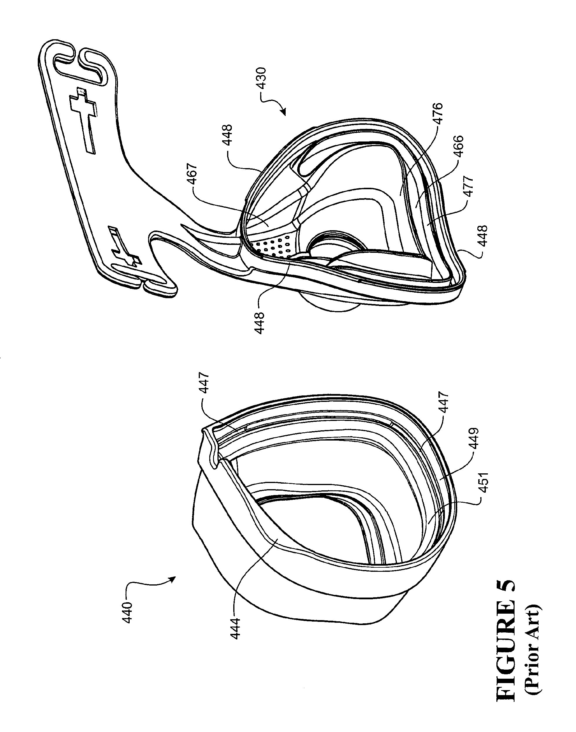
A further example of a way in which differently sized users are accommodated is the nasal mask range disclosed in US2010/0006101, the entire contents of which are hereby incorporated by reference herein. As shown in FIG. 1 of this application, three different sized mask bodies 430 and correspondingly sized seal assemblies 440 are provided. A user may select the most suitably sized frame and corresponding seal assembly for use. Various components of the nasal mask disclosed in US2010/0006101 are described below with reference to FIGS. 2 to 6.
The mask assembly 402 comprises a mask body 430 and a mask seal assembly 440. The mask body 430 provides the overall structural support for the mask assembly, and provides a clip type fitting 433 for attaching the mask assembly 402 to headgear 421. The mask body includes a forehead support 431 to which the headgear is also attached.
A rear side of the mask body 430 interfaces to the seal assembly 440. The seal assembly 440 provides a sealing interface against a user's face in use.
The mask body 430 has an inlet for receiving a flow of respiratory gases and exhaust holes 425 to allow exhaled breath to be vented from the mask assembly. The mask body forms an internal cavity to which respiratory gases are supplied via the inlet. The inlet comprises a tubular projection 422 extending from a front side 471 of the mask body 430. A connector 423 connects to the inlet and swivels with respect to the mask body 430, for connecting a supply conduit to the mask body.
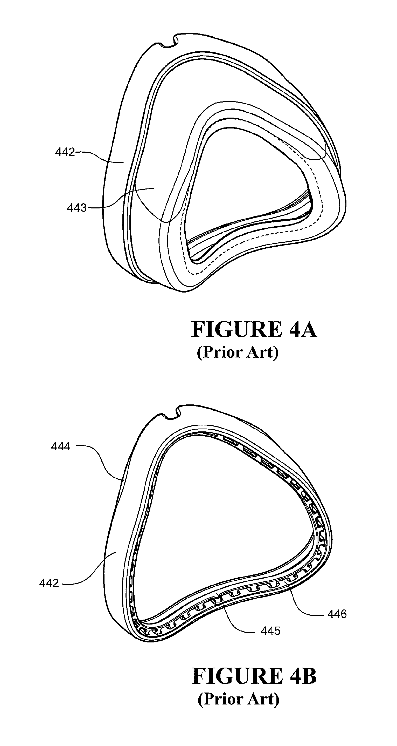
The seal assembly 440 comprises a flexible seal 443 attached to a relatively rigid plastic clip 442. The flexible seal 443 is over-moulded to the plastic clip 442 so that the seal assembly 440 forms a single item of the mask assembly 402. The plastic clip has a series of holes 446 around its perimeter. During manufacture, over moulding of the seal to the clip causes the seal material to flow through the series of holes 446. During manufacture, the seal material is cured. Once cured, the seal 443 is mechanically linked to the plastic clip 442 via holes 446, providing a mechanical joint between the clip and the seal. The holes 446 are located through a raised ridge 445 running around the inside perimeter of the clip.
The clip 442 releasably attaches to the mask body in a `clip` or `snap` type engagement. A series of bumps 448, or raised portions, on the mask body 430 interact with corresponding recesses 447 on the clip 442, to hold the clip 442 in place on the body 430. As the clip 442 attaches to the mask body, interference between the clip and each mask body bump 448 causes the clip or the mask body, or both, to deflect to a deflected condition until each bump 448 reaches a corresponding recess 447. Once the clip has been fully engaged with the body, each bump 448 locates within a corresponding recess 447, and the clip or body, or both un-deflect from the deflected condition to an un-deflected or partially deflected condition, the parts being clipped or snapped together in a fully engaged position.
The clip 442 preferably has a relatively long lead in, or ramped profile 449, leading to the clip recess 447. This lead in section extends the full inside perimeter length of the clip 442. The lead-in section assists with the attachment of the clip to the mask body. The clip 442 or mask body 430, or both, are gradually deflected over the length of the lead-in section until the apex of the lead-in section and each mask body bump 448 pass each other. Once the bumps 448 have passed over the lead-in section, the bumps 448 locate within each corresponding recess 447, such that there is little or no interference between the two parts 430 and 442. The two parts un-deflect in a relatively sudden snap action compared to the gradual deflection caused by the lead in section 449 during engagement.
The face seal assembly 440 includes at least one wing portion 444 to assist a user to disengage the face seal assembly from the mask body. The wing portions 444 provide a gripping flange to pull the clip 442 away from the mask body 430.
The nasal mask includes a cushion 441. Cushion 441 is provided around the periphery of the mask, and is surrounded by the seal assembly 440. The cushion 441 provides support to the seal 443 to achieve an effective seal onto the face of the user to reduce the likelihood of leakage.
One end 462 of the mask cushion is shaped to match the shape of the seal in contact with the user's face, and an opposite end 463 is shaped to match the mask body. The cushion includes a raised bridge 465 in the nasal bridge region. The raised bridge 465 can also be described as a cut out section made in the cushion, the cut out being on the mask body end 463 of the cushion. As the raised bridge 465 is unsupported by the mask body 430, it is much more flexible and results in less pressure on the nasal bridge of the patient.
The cushion 441 is located around the outer periphery of the mask body, contacting the mask body except for in the raised bridge portion 465 of the cushion. The cushion is located in a generally triangular cavity 466, the cavity continuing around the periphery of the body, terminating at each side of the nose bridge region 467 of the mask, where the raised bridge portion 465 of the cushion does not contact the mask body 430. The cavity 466 is generally formed by two spaced apart walls 476 and 477. The cushion 441 is a separate item, the seal assembly 440 fitting in place over the cushion to hold it in place within the mask assembly 402.
In this specification where reference has been made to patent specifications, other external documents, or other sources of information, this is generally for the purpose of providing a context for discussing the features of the invention. Unless specifically stated otherwise, reference to such external documents is not to be construed as an admission that such documents, or such sources of information, in any jurisdiction, are prior art, or form part of the common general knowledge in the art.
SUMMARY OF THE INVENTION
An object of the present invention is to provide a patient interface which goes some way to overcoming disadvantages in the prior art or which will at least provide the users with a useful choice.
In one aspect, the present invention broadly consists in a mask assembly for use as part of an apparatus for supplying a flow of respiratory gases to a user, comprising:
a mask body having an inlet through which said flow of respiratory gases are provided to the interior of said mask body, the inlet adapted to be connected to a gases conduit,
a mask seal assembly comprising a seal of flexible material and a clip of rigid material,
the seal having a first side and a second side, the first side of the seal being shaped to approximately match the contours of a user's face and in use substantially seal against a user's face, the second side attached to said clip,
the clip providing an interface extending substantially the full perimeter or periphery of the mask seal assembly for releasably attaching the mask seal assembly to the mask body, and
wherein the clip comprises a bridging portion spanning outwards from the perimeter or periphery of the mask body to space at least a portion of the second side of the seal outwards from the perimeter or periphery of the mask body.
Preferably the mask assembly comprises an inner cushion located between the clip and the first side of the seal.
Preferably the inner cushion is located between the bridging portion of the clip and the first side of the seal.
Preferably the clip comprises a channel in the bridging portion, a first side of the inner cushion in use supporting the first side of the seal, and a second side of the inner cushion being received in the channel.
Preferably the seal is attached to a first side of the clip and a second side of the clip releasably attaches to the mask body, and the bridging portion spans between the first and second sides of the clip.
Preferably the seal assembly comprises a second seal of flexible material attached to the second side of the clip for forming a seal between the mask seal assembly and the mask body.
Preferably the bridging portion and the seal are sized according to one of a series of sizes, each one of the series of sizes suitable for sealing against a differently sized user's face.
Preferably the mask body is adapted for use with a plurality of the seal assemblies, at least one said seal assembly having a said bridging portion, each said seal assembly having a said seal sized according to one of a series of sizes, each one of the series of sizes suitable for sealing against a differently sized user's face, and the second side of the clip of each said seal assembly being the same or similar to be releasably attached to the mask body.
Preferably the seal and the second seal are integrally formed and joined together across the bridging portion.
Preferably the seal and the second seal are integrally formed and joined together across the bridging portion via a runner across or through the bridging portion.
Preferably the mask assembly comprises an inner cushion located between the mask body and the first side of the seal.
Preferably the mask assembly comprises a channel in the mask body, a first side of the inner cushion in use supporting the first side of the seal, and a second side of the inner cushion being received in the channel in the mask body.
Preferably the bridging portion has an outward dimension that is the same or similar around the perimeter or periphery of the mask body.
Preferably the bridging portion has an outward dimension that varies around the perimeter or periphery of the clip.
Preferably the outward dimension of the bridging portion is larger at a bottom portion of the seal assembly and smaller at an upper portion or nasal bridge region of the seal assembly.
Preferably the bridging portion tapers from a first outward dimension in the bottom portion of the mask assembly to a second outward dimension in the upper portion or nasal bridge region of the mask assembly.
Preferably each said seal assembly in the said plurality of seal assemblies has a bridging portion with a first outward dimension in the bottom of the mask assembly and a second outward dimension in the upper portion of the mask assembly and the first outward dimension is greater than the second outward dimension, and the second outward dimension of each said seal assembly is the same or similar, and the first outward dimension of each said seal assembly is different to the first outward dimension of the other said seal assemblies in said plurality of seal assemblies, the first outward dimension of each said seal assembly sized to be suitable for sealing against a differently sized user's face.
Preferably the bridging portion extends rearward away from a front of the mask body towards a user's face in use.
Preferably the mask body is adapted for use with a plurality of the seal assemblies, at least one said seal assembly having a said bridging portion, each said seal assembly having a seal of a different type comprising one of a cannula seal, a nasal seal, a mouth seal and a full face seal, and the second side of the clip of each said seal assembly being the same or similar to be releasably attached to the mask body.
Preferably the mask seal assembly releasably attaches to a rear perimeter of the mask body.
Preferably the rear perimeter of the mask body defines an area being more than ten times the area of the mask body inlet.
Preferably the bridging portion spaces the second side of the seal outwards from the perimeter or periphery of the mask body by at least 10 mm.
Preferably the mask body defines a hollow space for receiving or covering a user's nose or mouth or both.
In another aspect, the present invention broadly consists in a mask package comprising:
a mask body having an inlet through which a flow of respiratory gases are provided to the interior of the mask body, the inlet adapted to be connected to a gases conduit,
a first seal assembly comprising:
a first seal of a flexible material and a first clip of a rigid material, the first seal having a first side and a second side, the first side of the first seal being shaped to approximately match the contours of a user's face and in use substantially seal against a user's face, said second side of said first seal attached to said first clip,
the first clip providing an interface extending substantially the full perimeter or periphery of the first seal assembly, the second side of the first seal attached to a first side of the first clip and a second side of the first clip for releasably attaching the first seal assembly to the mask body,
a second seal assembly comprising:
a second seal of a flexible material and a second clip of a rigid material, the second seal having a first side and a second side, the first side of the second seal being shaped to approximately match the contours of a user's face and in use substantially seal against a user's face, said second side of said second seal attached to said second clip,
the second clip providing an interface extending substantially the full perimeter or periphery of the second seal assembly, the second side of the second seal attached to a first side of the second clip and a second side of the second clip for releasably attaching the second seal assembly to the mask body,
wherein the first clip or the second clip or both comprises a bridging portion spanning outwards from the perimeter or periphery of the mask body to space at least a portion of the second side of the first or second seal outwards from the perimeter or periphery of the mask body when the first or second seal assembly is attached to the mask body, and the first side of the first clip being comparatively different to the first side of the second clip, and the first seal being comparatively different to the second seal.
Preferably the mask package comprises a first inner cushion for use with the first seal assembly and a second inner cushion for use with the second seal assembly.
Preferably the first seal assembly attached to the mask body, the first inner cushion is located between the first clip and the first side of the first seal, or with the second seal assembly attached to the mask body, the second inner cushion is located between the second clip and the first side of the second seal.
Preferably the first seal assembly attached to the mask body, the first inner cushion is located between the bridging portion of the first clip and the first side of the first seal, or with the second seal assembly attached to the mask body, the second inner cushion is located between the bridging portion of the second clip and the first side of the second seal.
Preferably the bridging portion of the first clip of the first seal assembly has a channel for receiving the first inner cushion, or/and the bridging portion of the second clip of the second seal assembly has a channel for receiving the second inner cushion.
Preferably the bridging portion of the first clip of the first seal assembly has an outward dimension that varies around the perimeter of the first clip, or the bridging portion of the second clip of the second seal assembly has an outward dimension that varies around the perimeter of the first clip.
Preferably the bridging portion of the first clip of the first seal assembly has a larger outward dimension at the bottom of the first seal assembly compared to the outward dimension at the top or nasal bridge region of the first seal assembly, and/or the bridging portion of the second clip of the second seal assembly has a larger outward dimension at the bottom of the second seal assembly compared to the outward dimension at the top or nasal bridge region of the second seal assembly.
Preferably the bridging portion of the second clip of the second seal assembly has a larger outward dimension at the bottom of the second seal assembly compared to the bridging portion of the first clip of the first seal assembly, the second seal of the second seal assembly being larger than the first seal of the first seal assembly.
Preferably the bridging portion of the first clip of the first seal assembly and the bridging portion of the second clip of the second seal assembly have the same or a similar outward dimension in the nasal bridge region of the clip.
Preferably the first side of the second seal has a longer perimeter length than the first side of the first seal.
Preferably a mask assembly comprising the mask body and the first seal assembly has an internal cavity having a first depth, and a mask assembly comprising the mask body and the second seal assembly has an internal cavity having a second depth, the second depth being greater than the first depth.
Preferably the bridging portion of the second clip of the second seal assembly extends rearward away from the general plane of the mask body when the second seal assembly is attached to the mask body.
Preferably the first seal assembly comprises a seal of flexible material attached to the second side of the first clip for forming a seal between the first mask seal assembly and the mask body, and/or
the second seal assembly comprises a seal of flexible material attached to the second side of the second clip for forming a seal between the second mask seal assembly and the mask body.
Preferably the first seal of the first seal assembly and the seal on the second side of the first clip of the first seal assembly are integrally formed and joined together across the bridging portion of the first clip, and/or
the second seal of the second seal assembly and the seal on the second side of the second clip of the second seal assembly are integrally formed and joined together across the bridging portion of the second clip.
Preferably a mask assembly comprising the mask body and the first seal assembly or the second seal assembly is a nasal mask or a full face mask.
Preferably the first side of the second clip has a longer perimeter length than the first side of the first clip, the second seal being larger than the first seal.
Preferably the first side of the second seal has a longer perimeter length than the first side of the first seal.
Preferably the first and second seals are different types of seals, the first and second seals being one of a cannula seal, a nasal seal, a mouth seal and a full face seal.
Preferably the first mask seal assembly and the second mask seal assembly releasably attach to a rear perimeter of the mask body.
Preferably the rear perimeter of the mask body defines an area being more than ten times the area of the mask body inlet.
Preferably the bridging portion of the first clip spaces the second side of the first seal outwards from the perimeter or periphery of the mask body by at least 10 mm, or the bridging portion of the second clip spaces the second side of the second seal outwards from the perimeter or periphery of the mask body by at least 10 mm.
Preferably the mask body defines a hollow space for receiving or covering a user's nose or mouth or both.
In another aspect, the present invention broadly consists in a mask assembly for use as part of an apparatus for supplying a flow of respiratory gases to a user, comprising:
a mask body having an inlet through which said flow of respiratory gases are provided to the interior of said mask body, the inlet adapted to be connected to a gases conduit,
a mask seal assembly comprising a seal of a flexible material and a clip of a rigid material,
said seal having a first side and a second side, the first side of said seal being shaped to approximately match the contours of a user's face and in use substantially seal against a user's face, said second side attached to said clip,
said clip providing an interface extending substantially the full perimeter or periphery of the mask seal assembly for releasably attaching the mask seal assembly to the mask body, and
an inner cushion located between the clip and said first side of the seal.
Preferably the clip comprises a bridging portion spanning outwards from the perimeter or periphery of the mask body to space at least the second side of the seal outwards from the perimeter or periphery of the mask body.
Preferably the inner cushion is located between the bridging portion and the first side of the seal.
Preferably the clip comprises a channel in the bridging portion, a first side of the inner cushion in use supporting the first side of the seal, and a second side of the inner cushion being received in the channel.
Preferably the seal is attached to a first side of the clip and a second side of the clip releasably attaches to the mask body, and the bridging portion spans between the first and second sides of the clip.
Preferably the seal assembly comprises a second seal of flexible material attached to the second side of the clip for forming a seal between the mask seal assembly and the mask body.
Preferably the bridging portion and said seal are sized according to one of a series of sizes, each one of the series of sizes suitable for sealing against a differently sized user's face.
Preferably the mask body is adapted for use with a plurality of said seal assemblies, at least one said seal assembly having a said bridging portion, each said seal assembly having a said seal sized according to one of a series of sizes, each one of the series of sizes suitable for sealing against a differently sized user's face, and said second side of the clip of each said seal assembly being the same or similar to be releasably attached to the mask body.
Preferably the seal and the second seal are integrally formed and joined together across the bridging portion.
Preferably the seal and the second seal are integrally formed and joined together across the bridging portion via a runner across or through the bridging portion.
Preferably the mask assembly comprises an inner cushion located between the mask body and said first side of the seal.
Preferably the mask assembly comprises a channel in the mask body, a first side of the inner cushion in use supporting the first side of the seal, and a second side of the inner cushion being received in the channel in the mask body.
Preferably the bridging portion has an outward dimension that is the same or similar around the perimeter or periphery of the mask body.
Preferably the bridging portion has an outward dimension that varies around the perimeter or periphery of the clip.
Preferably the outward dimension of the bridging portion is larger at a bottom portion of the seal assembly and smaller at an upper portion or nasal bridge region of the seal assembly.
Preferably the bridging portion tapers from a first outward dimension in the bottom portion of the mask assembly to a second outward dimension in the upper portion or nasal bridge region of the mask assembly.
Preferably each said seal assembly in the said plurality of seal assemblies has a bridging portion with a first outward dimension in the bottom of the mask assembly and a second outward dimension in the upper portion of the mask assembly and the first outward dimension is greater than the second outward dimension, and the second outward dimension of each said seal assembly is the same or similar, and the first outward dimension of each said seal assembly is different to the first outward dimension of the other said seal assemblies in said plurality of seal assemblies, the first outward dimension of each said seal assembly sized to be suitable for sealing against a differently sized user's face.
Preferably the bridging portion extends rearward away from a front of the mask body towards a user's face in use.
Preferably the mask body is adapted for use with a plurality of the seal assemblies, at least one said seal assembly having a said bridging portion, each said seal assembly having a seal of a different type comprising one of a cannula seal, a nasal seal, a mouth seal and a full face seal, and the second side of the clip of each said seal assembly being the same or similar to be releasably attached to the mask body.
Preferably the mask seal assembly releasably attaches to a rear perimeter of the mask body.
Preferably the rear perimeter of the mask body defines an area being more than ten times the area of the mask body inlet.
Preferably the bridging portion spaces the second side of the seal outwards from the perimeter or periphery of the mask body by at least 10 mm.
Preferably the mask body defines a hollow space for receiving or covering a user's nose or mouth or both.
In another aspect, the present invention broadly consists in a mask seal assembly for use as part of an apparatus for supplying a flow of respiratory gases to a user, comprising:
a seal of flexible material and a clip of rigid material,
the seal having a first side and a second side, the first side of the seal being shaped to approximately match the contours of a user's face and in use substantially seal against a user's face, the second side attached to said clip,
the clip providing an interface extending substantially the full perimeter or periphery of the seal assembly, the clip having a first side and a second side, the second side of the seal being attached to the first side of the clip, and the second side of the clip for releasably attaching the mask seal assembly to a mask body,
wherein the clip comprises a bridging portion spanning between the first and second sides of the clip to space at least a portion of the second side of the seal outwards from the perimeter or periphery of the second side of the clip.
Preferably the clip comprises a channel in the bridging portion for receiving an inner cushion for supporting the first side of the seal in use.
Preferably the seal assembly comprises a second seal of flexible material attached to the second side of the clip for forming a seal between the mask seal assembly and a mask body.
Preferably the bridging portion and the seal are sized according to one of a series of sizes, each one of the series of sizes suitable for sealing against a differently sized user's face.
Preferably the seal and the second seal are integrally formed and joined together across the bridging portion.
Preferably the seal and the second seal are integrally formed and joined together across the bridging portion via a runner across or through the bridging portion.
Preferably the bridging portion has an outward dimension that is the same or similar around the perimeter or periphery of the mask seal assembly.
Preferably the bridging portion has an outward dimension that varies around the perimeter or periphery of the clip.
Preferably the outward dimension of the bridging portion is larger at a bottom portion of the seal assembly and smaller at an upper portion or nasal bridge region of the seal assembly.
Preferably the bridging portion tapers from a first outward dimension in the bottom portion of the mask assembly to a second outward dimension in the upper portion or nasal bridge region of the mask assembly.
Preferably the bridging portion extends rearward away from a front of a mask body to which the mask assembly is attached in use and towards a user's face in use.
Preferably the mask seal assembly is adapted to releasably attach to a rear perimeter of a mask body defining a hollow space for receiving or covering a user's nose or mouth or both and having an inlet through which the flow of gases are provided to the interior of the mask body.
Preferably the rear perimeter of the mask body defines an area being more than ten times the area of the mask body inlet.
Preferably the bridging portion spaces the second side of the seal outwards from the perimeter or periphery of the second side of the clip by at least 10 mm.
The term "comprising" is used in the specification and claims, means "consisting at least in part of. When interpreting a statement in this specification and claims that includes "comprising", features other than that or those prefaced by the term may also be present. Related terms such as "comprise" and "comprises" are to be interpreted in the same manner. The invention consists in the foregoing and also envisages constructions of which the following gives examples.
For purposes of summarizing the invention and the advantages achieved over the prior art, certain objects and advantages of the invention have been described above and as further described below. Of course, it is to be understood that not necessarily all such objects or advantages may be achieved in accordance with any particular embodiment of the invention. Thus, for example, those skilled in the art will recognize that the invention may be embodied or carried out in a manner that achieves or optimizes one advantage or group of advantages as taught herein without necessarily achieving other objects or advantages as may be taught or suggested herein.
All of these embodiments are intended to be within the scope of the invention herein disclosed. These and other embodiments of the present invention will become readily apparent to those skilled in the art from the following detailed description of the preferred embodiments having reference to the attached figures, the invention not being limited to any particular preferred embodiment(s) disclosed.
BRIEF DESCRIPTION OF THE DRAWINGS
Preferred forms of the present invention will now be described with reference to the accompanying drawings. The appended drawings are schematic, not necessarily drawn to scale, unless otherwise indicated, and are meant to illustrate and not to limit embodiments of the invention.
FIG. 1 illustrates three differently sized prior art mask frames and corresponding seal assemblies.
FIG. 2 is a perspective view of the nasal mask of FIG. 1.
FIG. 3 is an exploded view of the nasal mask of FIG. 1.
FIG. 4a is a perspective view of the mask seal assembly of the nasal mask of FIG. 1.
FIG. 4b is a perspective view of the seal clip of the mask seal assembly of the nasal mask of FIG. 1.
FIG. 5 is a perspective view showing the mask body and the mask seal assembly of the nasal mask of FIG. 1, with the mask seal assembly removed from the mask body.
FIG. 6 is a sectional view on line X-X of the nasal mask of FIG. 2.
FIG. 7 is a block diagram of a humidified continuous positive airway pressure system as might be used in conjunction with the mask assembly of the present invention.
FIG. 8 is a cross sectional view of a mask assembly according to one embodiment of the present invention.
FIGS. 9A to 9C are part sectional views of a lower portion of a series of three differently sized mask assemblies.
FIGS. 10A to 10C are part sectional views of a lower portion of three alternative mask assemblies each having a `large` sized seal assembly.
FIGS. 11A to 11C are part sectional views of a lower portion of three alternative mask assemblies each having a `medium` sized seal assembly.
FIG. 12 is a diagram showing part sectional views of a common mask body and a range of mask seal assemblies for attachment to the common mask base.
FIG. 13 is a perspective view of a mask assembly comprising the present invention with section cut away to show a lower portion of the mask assembly in cross section.
FIGS. 14A to 14D show cross sections of alternative seal arrangements for forming a seal between a seal assembly and a mask body of a mask assembly comprising the present invention.
FIGS. 15A and 15B are part sectional views of a lower portion of two alternative mask assemblies each with a first seal and a second seal joined together across a bridging portion of a seal clip.
DETAILED DESCRIPTION OF THE PREFERRED EMBODIMENT
It will be appreciated that the mask assembly as described in the preferred embodiment of the present invention can be used in respiratory care generally or with a ventilator, but will now be described below with reference to use in a humidified Continuous Positive Airway Pressure (CPAP) system. It will also be appreciated that the present invention can be applied to various forms of mask assembly including, but not limited to, nasal masks and full face masks that cover both the user's nose and mouth.
With reference to FIG. 7 a humidified CPAP system is shown in which a patient 1 is receiving humidified and pressurised gases through a patient interface 2 connected to a supply conduit 3. It should be understood that CPAP is used generically and includes a range of variants including VPAP (Variable Positive Airway Pressure) and BiPAP (Bi-level Positive Airway Pressure) and numerous other forms of respiratory therapy.
Supply conduit 3 is connected to the outlet 4 of a humidification chamber 5 that contains a volume of water 6. Supply conduit 3 may contain a heater or heater wires (not shown) which heat the walls of the conduit or the gases in the conduit to reduce condensation of humidified gases within the conduit. Humidification chamber 6 is preferably formed from a plastics material. The contents of the chamber are heated by a heater. For example the chamber may have a highly heat conductive base (for example an aluminium base) which is in direct contact with a heater plate 7 of humidifier 8. Humidifier 8 is provided with control means or electronic controller 9 which may comprise a microprocessor based controller executing computer software commands stored in associated memory.
Controller 9 receives input from sources such as a user interface or dial 10 through which a user of the device may, for example, set a value (e.g., a preset or predetermined value) of humidity or temperature of the gases to be supplied. The controller may also receive input from other sources; for example temperature and/or flow velocity sensors 11 and 12 through connector 13 and heater plate temperature sensor 14. In response to the user set humidity or temperature value input via dial 10 and the other inputs, controller 9 determines when (or to what level) to energise heater plate 7 to heat the water 6 within humidification chamber 5. As the volume of water 6 within humidification chamber 5 is heated, water vapour begins to fill the volume of the chamber above the water's surface and is passed out of the humidification chamber 5 outlet 4 with the flow of gases (for example air) provided from a gases supply means or blower 15 which enters the chamber through inlet 16. Exhaled gases from the patient's mouth are passed directly to ambient surroundings in FIG. 1.
Blower 15 is provided with variable pressure regulator or a variable speed fan 21. The fan draws air or other gases through blower inlet 17. The speed of the variable speed fan 21 is controlled by electronic controller 18 (or alternatively the function of controller 18 could carried out by controller 9) in response to inputs from controller 9.
Mask Assembly
A mask assembly 2 according to the present invention is described with reference to FIGS. 8 to 13. FIG. 8 shows a mask comprising a mask body 30. The mask body includes an inlet 22 for receiving a flow of gases into the mask assembly. The mask body preferably includes features for securing the mask assembly in position on the user's face. For example, the embodiment of FIG. 8 includes a forehead rest 31 to assist with correct placement of the mask assembly against the user's face, and a clip 33 for attachment to headgear. Headgear may also be attached to features of the forehead rest. The mask body may include other known features, for example vent holes 25 for venting expired gases and air, and a channel 66 for receiving an inner cushion (not shown) for supporting the seal 43.
A seal assembly 40 comprising a seal 43 of a flexible material and clip 42 of a rigid material is attached to a rear side of the mask body. A first side of the flexible seal contacts a user's facial features in use. A second side of the flexible seal is attached to the clip. The seal assembly is releasably attached to the mask body 30 by the clip. Preferably the clip extends substantially the full perimeter of the mask seal assembly. The clip is rigid compared to the seal material and provides a convenient interface for releasably attaching the flexible seal to the mask body. For example, the clip is manufactured from polycarbonate, ABS, nylon, acetyl or other similar rigid plastic. Alternatively the clip may be made from a high Shore A hardness silicone. For example, a silicone with a Shore A hardness of 90 may provide sufficient rigidity. The clip and mask body may be manufactured from the same material type. The seal is formed from rubber or other suitable flexible, resilient material. Preferable the seal is formed from silicone with a Shore-A hardness of less than 60. Preferably the seal is made from silicone with a Shore A hardness of 20-40.
From the above mentioned materials, the difference in rigidity of the clip material (rigid) and the seal material (flexible) will be appreciated. For example, polycarbonate has a Young's modulus of approximately 2 GPa, whereas the Young's modulus of a rubber or other suitable material for use as the flexible seal is in the order of 1 to 5 MPa.
The seal generally provides a flexible perimeter about the perimeter or periphery of the mask body. The seal surrounds an opening to the inside of the mask assembly. A nasal mask assembly seals against a user's face around the user's nose, the seal opening covering the user's nose. A full face mask seals against a user's face around the users nose and mouth, the seal opening covering both the user's nose and mouth.
The clip has a bridging portion 50 that spans outwards from the perimeter or periphery of the mask body 30. The bridging portion spaces at least a portion of the second side of the flexible seal 43 outwards from the perimeter or periphery of the mask body to which the clip is attached.
The mask body 30 may be used with a conventional seal assembly as disclosed in the prior art, for example as illustrated in FIG. 4A. Where a larger mask may be used by a larger user, the same mask body 30 useable with the conventional seal assembly may be used together with a seal assembly comprising a clip with a bridging portion 50. The bridging portion 50 allows a larger flexible seal 43 to be attached to the mask body 30, as illustrated in FIG. 8.
The present invention allows a single mask body 30 to be used for a range of differently sized users. For example, a range of differently sized seal assemblies may be provided. Each seal assembly may have a clip including a bridging portion 50. The bridging portion of each seal assembly may be a different size and each clip may be attached to a different size flexible seal. A smallest seal assembly in a range of differently sized seal assemblies may not include a bridging portion, the smallest seal assembly being a standard or conventional type seal assembly, for example as illustrated in FIG. 4A.
For supply to a user, a packaged interface product may include a single mask body, and a plurality of these seal assemblies, each of a different size with at least one of the seal assemblies having a bridging portion. The package may include instructions for selection and assembly of the seal assemblies to the mask body 30. The plurality of different size seal assemblies may be varied according to their size, by the size and arrangement of the bridging portion, the placement of an inner cushion and other aspects of variation described in this specification.
The range of seal assemblies for use with a single mask body preferably each have an identical or at least similar connection portion or side for attaching to the single mask body.
The clip with bridging portion expands a mask body to a larger size for use with a larger flexible seal. The mask body may be used with a first seal assembly comprising a flexible seal and clip without a bridging portion, for example as shown in FIG. 9C. The same mask body may be used with one or more seal assemblies each comprising a flexible seal and clip with a bridging portion to expand the mask body for use with a larger seal. A series of seal assemblies may be provided, each seal assembly in the series having a clip with a progressively larger bridging portion and corresponding larger flexible seal. A plurality of seal assemblies with clips each having differently sized bridging portions may be provided to achieve a range of mask assemblies, for appropriate selection by a user, as illustrated in FIGS. 9A and 9B.
As shown in FIG. 8, preferably the bridging portion of the clip has an outward dimension D that varies around the perimeter or periphery of the mask body. As shown in FIG. 8, preferably the outward dimension of the bridging portion is larger at a bottom portion of the clip and smaller at an upper portion of the clip. Alternatively, the bridging portion may have an outward dimension the same or similar around the periphery of the mask body.
The outward dimension of the bridging portion of a number of different seal assemblies may be the same in a particular portion of the mask body perimeter or periphery to which the clips are attached. For example, a range of different seal assemblies each may comprise a clip with bridging portion having a similar or the same outward dimension in the nasal bridge region, and each clip having a different outward dimension outside the nasal bridge region.
A mask according to the present invention may include a mask body having a forehead rest, for example as shown in FIG. 8. It can be advantageous for a mask having a forehead rest to have a range of different seal assemblies each comprising a clip with bridging portion having a similar or the same outward dimension in the nasal bridge region. With each clip in the range of seal assemblies having a similar outward dimension in the nasal bridge region, the distance between the top of the seal assembly and the forehead rest remains the same across the range of different sized seal assemblies. This is preferred as the distance the forehead rest is above the top of the mask body can be sized to be suitable for use with a range of different sized seal assemblies. By comparison, in a less preferred embodiment of the present invention, each seal assembly has a clip with bridging portion having a substantially constant outward dimension around the full parameter of the seal assembly. For larger seals, the distance between the top of the seal and the forehead rest therefore decreases.
The distance between the top of the seal and the forehead rest ideally should increase for increasing sized users. With each seal in a range of seals having the same bridging portion outward dimension in the nasal bridge region, the distance between the forehead rest and the top of each seal is the same, which is preferred to the previously described less preferred embodiment.
Preferably the clip has a bridging portion that tapers from a first outward dimension in a lower section of the seal to a second outward dimension in the nasal bridge region, the first dimension being greater than the second dimension.
The embodiment of FIG. 8 is illustrated without an inner cushion between the mask body 30 and the flexible seal 43. Preferably the mask assembly comprises an inner cushion between the mask body 30 and the flexible seal 43, or an inner cushion between the clip and the flexible seal.
FIGS. 10A to 10C illustrate alternative clips with a bridging portion in the lower portion of the seal assembly for providing a `large` sized seal 43 compared to other sealing assemblies. In each embodiment of FIGS. 10A to 10C, an inner cushion is located between the clip and the first side of the flexible seal 43. Preferably the inner cushion is located between the clip bridging portion and the first side of the flexible seal.
Preferably the bridging portion comprises a channel 67 for receiving and locating a side of the inner cushion at the clip. The channel may extend around a full circumference of the clip, or the channel may extend around a portion of a circumference of the clip. For example, the channel may extend around the clip outside the nasal bridge region only for use with a cushion having a raised nasal bridge region similar to the configuration of the inner cushion described in US2010/0006101.
In the embodiment of FIG. 10B, the bridging portion extends outwardly from the mask body 30 and also rearward, away from the general plane of the mask body, towards the user in use. The mask body and seal assembly combine to provide a cavity for surrounding the user's nose, or mouth or both. The rearward extension of the clip bridging portion increases the depth of the cavity provided by the mask assembly. For example, the depth D.sub.B of the cavity provided by the assembly of FIG. 10B with a rearward extension of the clip bridging portion is deeper than the depth D.sub.A of the cavity of the assembly of FIG. 10A with a clip bridging portion that does not extend rearward. The rearward extension of the bridging portion 50 of the embodiment of FIG. 10B spaces the second side of the seal 43 rearward from the perimeter or periphery of the mask body. For larger sized users, for example a user with a larger nose, a deeper internal cavity provided by the mask body and seal clip may reduce the likelihood of the user's nose touching an inside surface of the mask body compared to a mask assembly comprising a smaller seal 43. Extending the second side of the flexible seal 43 rearwards by providing a clip with a rearward extending bridging portion provides a deeper cavity to receive the user's nose compared to a mask assembly having a clip without a rearward extending bridging portion.
In the alternative embodiment of FIG. 10C, a deeper mask cavity is created compared to the embodiment of FIG. 10A by providing a deeper inner cushion and flexible seal for sealing against the user's face. The embodiments of FIGS. 10A and 10C each have the same shaped clip with bridging portion.
FIGS. 11A to 11C illustrate alternative clips with a bridging portion in the lower portion of the seal assembly for providing a `medium` sized seal compared to other sealing assemblies. For example, the bridging portions 50 of the embodiments of FIGS. 11A to 11C have a smaller outward dimension compared to the bridging portions 50 of the embodiments of FIGS. 10A to 10C so that the seal 43 of the embodiments of FIGS. 11A to 11C are smaller than the seals of the embodiments of FIGS. 10A to 10C. And the bridging portions 50 of the embodiments of FIGS. 11A to 11C each provide a seal 43 that is larger than the seal of the illustrative embodiment comprising a clip with a bridging portion having a smaller outward dimension, or an embodiment comprising a clip without a bridging portion, for example the illustrative embodiment of FIG. 9C.
In the embodiment of FIG. 11A, an inner cushion 41 is located between the mask body 30 and the first side of the flexible seal 43, similar in concept to the aforementioned nasal mask illustrated in FIGS. 1-6. A channel 66 is formed in the mask body by two spaced apart members 76 and 77. A side of the inner cushion 41 in contact with the mask body is received in the channel 66.
FIGS. 11B and 11C illustrate embodiments similar to the embodiment of FIG. 10A described above, with the inner cushion located between the clip 42 and the flexible seal 43. However the outward dimension of the clip bridging portion of the `medium` seal assemblies of FIGS. 11B and 11C is smaller than the outward dimension of the `large` clip of the embodiment of FIG. 10A.
Due to the smaller bridging portion of the clip of the medium seal assembly of FIG. 11B, the side of the inner cushion in contact with the clip may be reduced in cross section compared to the inner cushion of the large seal assemblies of FIGS. 10A to 10C. In the alternative embodiment of FIG. 11C, a channel for receiving the cushion in the seal assembly is formed by material of the flexible seal that contacts a user's face in use, and material of a second flexible seal 44 on the other side of the bridging portion 50. The second flexible seal 44 is discussed below.
One embodiment of the present invention comprises a packaged mask assembly product including a single mask body and a plurality of seal assemblies of different sizes for use with the single mask body. For example, a mask package may include a single mask body 30 and a first seal assembly 540, a second seal assembly 640, and a third seal assembly 740, as shown in FIG. 12. The first seal assembly has a clip 542 and seal 543. The clip 542 does not have a bridging portion, the second side 5432 of the seal attached to the clip is not spaced outwards of the mask body when the seal assembly is attached to the mask body. For example, a portion of the material forming the seal 543 also forms a seal against the mask body. The mask assembly comprising the mask body 30 and the first seal assembly 540 may also include an inner cushion 541 located between the first side 5431 of the seal 542 and the mask body 30. The inner cushion is received in the channel 66 of the mask body 30. The mask assembly comprising the first seal assembly 540 is most suited to users with smaller facial features compared to other users.
Where the first seal assembly is not large enough for a particular user, that user may chose to use the second seal assembly 640. The second seal assembly has a clip 642 and seal 643. The clip 642 has a bridging portion 650 to space the second side 6432 of the seal attached to the clip outwards of the mask body when the seal assembly is attached to the mask body. The bridging portion has an outward dimension D.sub.m to space the second side of the seal outwards from the mask body by a distance. The bridging portion 650 of clip 642 allows a larger seal to be used with the body 30 by comparison with the seal of the first seal assembly 540. For example, the seal 643 attached to clip 642 of the second seal assembly 640 may be taller and wider in places compared to the seal 543 of the first seal assembly 540.
The mask assembly comprising the mask body 30 and the second seal assembly 640 may also include an inner cushion 641. In the illustrated example, the inner cushion 641 is located between the first side 6431 of the seal 643 and clip 642. The inner cushion 641 is received in the channel 667 of the clip 642.
Where the second seal assembly is not large enough for a particular user, that user may chose to use the third seal assembly 740. The third seal assembly has a clip 742 and seal 743. The clip 742 has a bridging portion 750 to space the second side 7432 of the seal attached to the clip outwards of the mask body when the seal assembly is attached to the mask body. The bridging portion has an outward dimension D.sub.L to space the second side of the seal outwards from the mask body by a distance. By comparison, the outward dimension of the bridging portion 750 of the third seal assembly 740 is larger than the outward dimension of the bridging portion 650 of the second seal assembly 640. The bridging portion 750 of clip 742 allows a larger seal to be used with the body 30 by comparison with the seal of the second seal assembly 640. For example, the seal 743 attached to clip 742 of the third seal assembly 740 may be taller and wider in places compared to the seal 743 of the second seal assembly.
The mask assembly comprising the mask body 30 and the third seal assembly 740 may also include an inner cushion 741. In the illustrated example, the inner cushion 741 is located between the first side 7431 of the seal 743 and clip 742. The inner cushion 741 is received in the channel 767 of the clip 742.
It can be seen from FIG. 12 that incorporating a bridging portion into the clip of a plurality of seal assemblies, each one with a different sized bridging portion, provides for a series of differently sized seal assemblies for use with a common mask body. A series of seal assemblies, each with a bridging portion with an increased outward dimension provides a series of increasing sized seal assemblies for use with a common mask body.
The seal of a seal assembly generally provides a flexible perimeter about the perimeter or periphery of the mask assembly. The seal surrounds an opening to the inside of the mask assembly. A second seal described as being larger than a first seal has a larger perimeter and opening than the first smaller seal. For example, the present invention may comprise a nasal mask package comprising a common mask body and a series of differently sized seal assemblies, each having a perimeter adapted to seal about a user's nose, the user's nose being received in an opening of the seal. Alternatively, the present invention may comprise a full face mask package comprising a common mask body and a series of differently sized seal assemblies, each having a perimeter adapted to seal about a user's nose and mouth, the user's nose and mouth being received in an opening of the seal.
Furthermore, a second seal described as being larger than a first seal not only has a larger perimeter and opening than the first smaller seal, but preferably also has a deeper seal assembly depth. The depth of a seal assembly is indicated in FIG. 12 by dimensions D.sub.1, D.sub.2 and D.sub.3 for the three different sized seals illustrated. As shown, the depth of the seal assemblies increases for increasing seal sizes.
A large range of users can be accommodated by providing three different size mask seals for use with a common body. The three different size seals may conveniently be labeled as small, medium and large. A nasal mask suitable for a range of smaller users may have a seal height from the bridge of the nose to the philtrum area of around 45 mm. A nasal mask suitable for a range of medium sized users may have a seal height from the bridge of the nose to the philtrum area of around 54 mm. According to the present invention, the difference in height between the small seal and the medium seal is accommodated by the outward dimension of the bridging portion of the clip of the medium seal assembly. A nasal mask suitable for a range of larger sized users may have a seal height from the bridge of the nose to the philtrum area of around 58 mm. Similarly, according to the present invention, the difference in height between the small seal and the large seal is accommodated by the outward dimension of the bridging portion of the clip of the large seal assembly, the outward dimension of the bridging portion of the clip of the large seal assembly being greater than the outward dimension of the bridging portion of the clip of the medium seal assembly.
A series of differently sized seal assemblies may comprise a feature or features that are common to more than one seal assembly in the series. For example, a plurality of seal assemblies in a series of seal assemblies may each have the same or a similarly shaped nasal bridge region.
The present invention allows for a range of different types of seals to be used with a common mask body. For example, a common mask body may be used with a nasal seal assembly comprising a clip and seal for sealing around the nose of a user. The same mask body may also be used with a full face seal assembly comprising a clip and a seal for sealing around the nose and mouth of a user.
The seal of each seal assembly is attached to a first side of the seal assembly clip. A second side of the clip attaches to the common mask body. Each seal assembly clip has an identical or at least similar connection portion or second side for attaching to the common mask body. The clip of each seal assembly has a different first side to allow different types of seals to be used with the common mask body. The portion of the clip spanning between the first and second sides of the clip allows a different size or type of seal to be used with the common mask body. For example, the seal and first side of the clip of a full face seal assembly has a longer perimeter length than the seal and first side of the clip of a nasal seal assembly. The difference in perimeter lengths of the first sides of the clips of the full face and nasal seal assemblies is achieved by the clip of the full face seal assembly having bridging portion spanning between the first and second sides of the clip with a larger outward dimension than the clip of the nasal seal assembly. For example, the clip of the nasal seal assembly may have a bridging portion with a smaller outward dimension than the clip of the full face seal assembly, or the clip of the nasal seal assembly may not have a bridging portion, the second side of the seal of the nasal seal assembly not being spaced outwardly from the perimeter of the common mask body.
A range of different types of seals, each with a clip having a different first side allows many different types of seals to be used with a common mask body. For example the common mask body may be used with a cannula seal assembly, a nasal seal assembly, a mouth seal assembly and a full face assembly.
As described above, a sealing assembly according to one embodiment of the present invention comprises a rigid clip having a bridging portion for spacing the second side of the flexible seal in contact with a user's face outwards from the perimeter of the mask body. The flexible seal is attached to a first side of the clip. A second side of the clip attaches to the mask body. The bridging portion of the clip spans between the first and second sides of the clip.
Preferably the seal assembly further comprises a second flexible seal 44 attached to the second side of the clip for forming a seal between the seal assembly 40 and the mask body 30, as shown in FIGS. 10A to 14B. The bridging portion 50 spans between a first seal 43 for forming a seal against a user's face, and a second seal 44 for forming a seal between the seal assembly and the mask body 30.
The first and second seals may be integrally formed, for example in an injection moulding process, the first and second seals integrally formed and joined together via a runner across or through the bridging portion. Alternatively, the first and second seals may be joined by overmoulding the seal material from the first flexible seal to the second flexible seal across the bridging portion as illustrated in FIGS. 15A and 15B. Alternatively, the first and second seals may be separately formed, for example by providing multiple insertion points, a multiple stage moulding process, or by a runner subsequently removed.
Various second seal configurations for sealing between the seal assembly and the mask body are illustrated in FIGS. 14A to 14D. As illustrated in FIG. 14A, the second seal 44 has a bearing surface 51 extending around the perimeter of the clip. The second seal bearing surface 51 faces a corresponding bearing surface 52 on the mask body. The seal bearing surface and the mask bearing surface are in contact when the seal assembly is attached to the mask body in a butting engagement. When the seal assembly 40 is attached to the mask body 30, the second seal 44 at the bearing interface is compressed so that a sealing interface is formed between the seal assembly and the mask body.
Preferably, the clip has a raised ridge 45 running around the inside perimeter of the clip. The second seal 44 is compressed when the clip is attached to the mask body by being squashed between the raised ridge 45 and the mask body bearing surface 52 when the seal assembly 40 is attached to the mask body 30.
To assist with creating a good seal between the seal assembly and the mask body, a continuous rim 53 may be provided on the seal bearing surface 51. The rim provides a small contact area in contact with the mask body bearing surface 52. The small contact area allows a relatively high compression of the rim, and therefore effective seal, for a relatively small seal assembly to mask body engagement force.
The alternative sealing arrangement illustrated in FIG. 14B comprises a seal that slides against a corresponding lateral member of the mask body during engagement of the seal assembly to the mask body. For example, a wall 77 forming a side of a channel 66 in the mask body for receiving the inner cushion as shown in FIG. 11A extends rearward to contact the second seal 44 when the seal assembly 40 is attached to the mask body 30. Preferably the second seal 44 comprises a raised rim 53 on the surface 51 that contacts the lateral member 77. The rim provides a small contact area in contact with the mask body bearing surface 52 in contact with the seal. The small contact area allows a relatively high compression of the rim, and therefore effective seal, for a relatively small seal assembly to mask body engagement force.
The alternative sealing arrangement illustrated in FIG. 14C comprises a lip 54 that bears against an end of a lateral member of the mask body 30. For example, a wall 77 forming a side of a channel 66 in the mask body for receiving the inner cushion as shown in FIG. 11A extends rearward to contact the lip 54 of the second seal 44 when the seal assembly 40 is attached to the mask body 30.
The alternative sealing arrangement illustrated in FIG. 14D is similar to the arrangement of FIG. 14B but includes two sealing rims 53 in sealing contact with a surface of the mask body.
The present invention has been described with reference to a nasal mask assembly. However, the present invention may equally be applied to other mask assemblies, for example full face masks that cover a user's nose and mouth.
Although certain preferred embodiments and examples have been discussed herein, it will be understood by those skilled in the art that the present invention extends beyond the specifically disclosed embodiments to other alternative embodiments and/or uses of the invention and obvious modifications and equivalents thereof. In addition, while a number of variations of the invention have been shown and described in detail, other modifications, which are within the scope of this invention, will be readily apparent to those of skill in the art based upon this disclosure. It is also contemplated that various combinations or sub-combinations of the specific features and aspects of the embodiments may be made and still fall within the scope of the invention. Accordingly, it should be understood that various features and aspects of the disclosed embodiments can be combined with or substituted for one another in order to form varying modes of the disclosed invention. Thus, it is intended that the scope of the present invention herein disclosed should not be limited by the particular disclosed embodiments described above, but should be determined only by a fair reading of the present disclosure, including the appended claims.
* * * * *
References
-
resmed.com/maskframes/mask.htm
-
-
homedepot.com/p/Everbilt-1-2-in-Galvanized-HexNut-804076/204647893
-
cpapxchange.com/cpap-machines-biap-machines/system-one-60-series-cpap-humidifier-manual.pdffrontcover
-
weddingbands.com/ProductPop-wedding-bands-metal/48214W.html
D00000
D00001
D00002
D00003
D00004
D00005
D00006
D00007
D00008
D00009
D00010
D00011
D00012

D00013

D00014

D00015
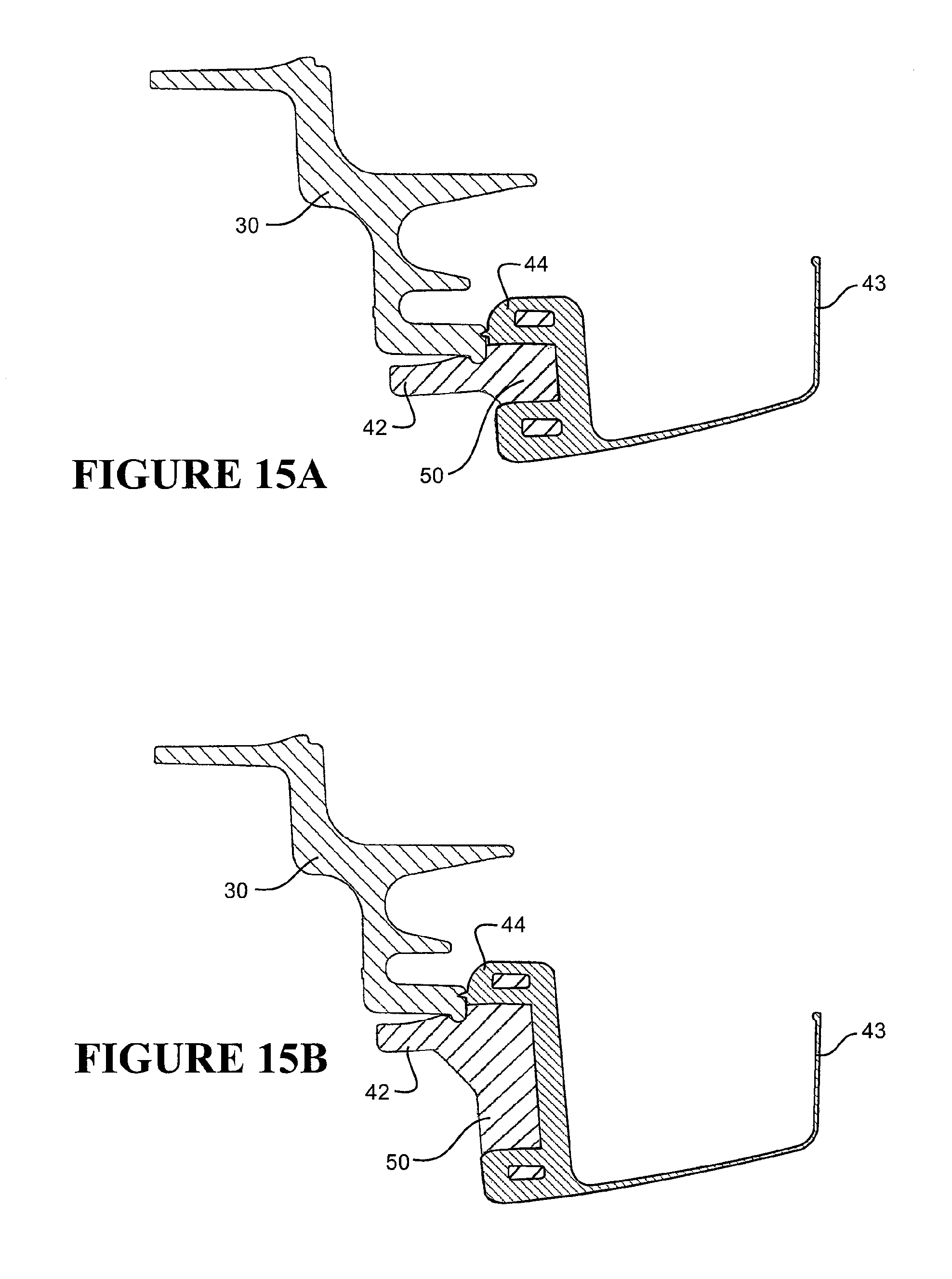
XML
uspto.report is an independent third-party trademark research tool that is not affiliated, endorsed, or sponsored by the United States Patent and Trademark Office (USPTO) or any other governmental organization. The information provided by uspto.report is based on publicly available data at the time of writing and is intended for informational purposes only.
While we strive to provide accurate and up-to-date information, we do not guarantee the accuracy, completeness, reliability, or suitability of the information displayed on this site. The use of this site is at your own risk. Any reliance you place on such information is therefore strictly at your own risk.
All official trademark data, including owner information, should be verified by visiting the official USPTO website at www.uspto.gov. This site is not intended to replace professional legal advice and should not be used as a substitute for consulting with a legal professional who is knowledgeable about trademark law.