Set of panels
Boo , et al. October 20, 2
U.S. patent number 10,808,410 [Application Number 16/220,748] was granted by the patent office on 2020-10-20 for set of panels. This patent grant is currently assigned to VALINGE INNOVATION AB. The grantee listed for this patent is Valinge Innovation AB. Invention is credited to Christian Boo, Anders Nilsson, Marcus Nilsson Stahl.


| United States Patent | 10,808,410 |
| Boo , et al. | October 20, 2020 |
Set of panels
Abstract
A set of panels including first and second panels. The first and second panels have a first, second and third edge. The first edge of the first panel is configured to be able to be locked together with both the second edge and the third edge of the second panel. The first edge includes a first locking element configured to be able to cooperate with a first locking groove at the second edge and a second locking groove at the third edge for locking in a horizontal direction. The first edge includes a tongue groove configured to cooperate with a tongue at the second edge and a tongue at the third edge for locking in a vertical direction. The first locking element includes a first locking surface configured to cooperate with a second locking surface on the first locking groove, for locking in the horizontal and the vertical direction.
| Inventors: | Boo; Christian (Kagerod, SE), Stahl; Marcus Nilsson (Hoganas, SE), Nilsson; Anders (Helsingborg, SE) | ||||||||||
|---|---|---|---|---|---|---|---|---|---|---|---|
| Applicant: |
|
||||||||||
| Assignee: | VALINGE INNOVATION AB (Viken,
SE) |
||||||||||
| Family ID: | 1000005125887 | ||||||||||
| Appl. No.: | 16/220,748 | ||||||||||
| Filed: | December 14, 2018 |
Prior Publication Data
| Document Identifier | Publication Date | |
|---|---|---|
| US 20190211569 A1 | Jul 11, 2019 | |
Foreign Application Priority Data
| Jan 9, 2018 [SE] | 1850026 | |||
| Current U.S. Class: | 1/1 |
| Current CPC Class: | E04F 15/102 (20130101); E04F 15/107 (20130101); E04F 15/02033 (20130101); E04F 15/105 (20130101); E04F 13/08 (20130101); E04F 15/02038 (20130101); E04F 2201/0161 (20130101); E04F 2201/023 (20130101); E04F 2201/0146 (20130101); E04F 2201/0153 (20130101); E04F 2201/0107 (20130101) |
| Current International Class: | E04F 15/02 (20060101); E04F 15/10 (20060101); E04F 13/08 (20060101) |
References Cited [Referenced By]
U.S. Patent Documents
| 1787027 | December 1930 | Wasleff |
| 3120083 | February 1964 | Dahlberg et al. |
| 3247638 | April 1966 | Gay et al. |
| 3538665 | November 1970 | Gohner |
| 3694983 | October 1972 | Couquet |
| 3720027 | March 1973 | Christensen |
| 3742669 | July 1973 | Mansfeld |
| 3760547 | September 1973 | Brenneman |
| 3857749 | December 1974 | Yoshida |
| 3919820 | November 1975 | Green |
| 4113399 | September 1978 | Hansen, Sr. et al. |
| 4172169 | October 1979 | Mawson et al. |
| 4176210 | November 1979 | Skinner |
| 4180615 | December 1979 | Bettoli |
| 4187131 | February 1980 | Shortway et al. |
| 4196554 | April 1980 | Anderson et al. |
| 4313866 | February 1982 | Renshaw |
| 4333987 | June 1982 | Kwart et al. |
| 4393187 | July 1983 | Boba et al. |
| 4423178 | December 1983 | Renshaw |
| 4426820 | January 1984 | Terbrack et al. |
| 4489115 | December 1984 | Layman et al. |
| 4507188 | March 1985 | Chu |
| 4512131 | April 1985 | Laramore |
| 4599841 | July 1986 | Haid |
| 4614680 | September 1986 | Fry et al. |
| 4772500 | September 1988 | Stroppiana |
| 4785065 | November 1988 | Uhl et al. |
| 4807412 | February 1989 | Frederiksen |
| 5007222 | April 1991 | Raymond |
| 5112671 | May 1992 | Diamond et al. |
| 5148850 | September 1992 | Urbanick |
| 5162141 | November 1992 | Davey et al. |
| 5182892 | February 1993 | Chase |
| 5344700 | September 1994 | McGath et al. |
| 5380794 | January 1995 | Schaefer et al. |
| 5441677 | August 1995 | Phillips, Sr. |
| 5458953 | October 1995 | Wang et al. |
| 5465546 | November 1995 | Buse |
| 5548937 | August 1996 | Shimonohara |
| 5618602 | April 1997 | Nelson |
| 5630304 | May 1997 | Austin |
| 5670237 | September 1997 | Shultz et al. |
| 5694730 | December 1997 | Del Rincon et al. |
| 5797237 | August 1998 | Finkell, Jr. |
| 5950389 | September 1999 | Porter |
| 6006486 | December 1999 | Moriau et al. |
| 6052960 | April 2000 | Yonemura |
| 6065262 | May 2000 | Motta |
| 6101778 | August 2000 | Martensson |
| 6139945 | October 2000 | Krejchi et al. |
| 6173548 | January 2001 | Hamar et al. |
| 6182410 | February 2001 | Pervan |
| 6209278 | April 2001 | Tychsen |
| 6216409 | April 2001 | Roy et al. |
| 6233899 | May 2001 | Mellert et al. |
| 6291078 | September 2001 | Chen et al. |
| 6324809 | December 2001 | Nelson |
| 6332733 | December 2001 | Hamberger et al. |
| 6345481 | February 2002 | Nelson |
| 6363677 | April 2002 | Chen |
| 6455127 | September 2002 | Valtanen |
| 6490836 | December 2002 | Moriau et al. |
| 6505452 | January 2003 | Hannig |
| 6536178 | March 2003 | Palsson et al. |
| 6546691 | April 2003 | Leopolder |
| 6553724 | April 2003 | Bigler |
| 6558070 | May 2003 | Valtanen |
| 6617009 | September 2003 | Chen et al. |
| 6647690 | November 2003 | Martensson |
| 6672030 | January 2004 | Schulte |
| 6675545 | January 2004 | Chen et al. |
| 6729091 | May 2004 | Martensson |
| 6761008 | July 2004 | Chen et al. |
| 6763643 | July 2004 | Martensson |
| 6766622 | July 2004 | Theirs |
| 6769218 | August 2004 | Pervan |
| 6769219 | August 2004 | Schwitte et al. |
| 6772568 | August 2004 | Thiers |
| 6790512 | September 2004 | MacQueen et al. |
| 6804926 | October 2004 | Eisermann |
| 6851241 | February 2005 | Pervan |
| 6854235 | February 2005 | Martensson |
| 6862857 | March 2005 | Tychsen |
| 6865855 | March 2005 | Knauseder |
| 6874292 | April 2005 | Moriau |
| 6880307 | April 2005 | Schwitte |
| 6895881 | May 2005 | Whitaker |
| 6928779 | August 2005 | Moriau et al. |
| 6986934 | January 2006 | Chen et al. |
| 7051486 | May 2006 | Pervan |
| 7090430 | August 2006 | Fletcher |
| 7121058 | October 2006 | Palsson et al. |
| 7155871 | January 2007 | Stone et al. |
| 7169460 | January 2007 | Chen et al. |
| 7171791 | February 2007 | Pervan |
| 7211310 | May 2007 | Chen et al. |
| 7251916 | August 2007 | Konzelmann et al. |
| 7275350 | October 2007 | Pervan et al. |
| 7337588 | March 2008 | Moebus |
| 7377081 | May 2008 | Ruhdorfer |
| 7398625 | July 2008 | Pervan |
| 7419717 | September 2008 | Chen et al. |
| 7451578 | November 2008 | Hannig |
| 7454875 | November 2008 | Pervan et al. |
| 7484337 | February 2009 | Hecht |
| 7552568 | June 2009 | Palsson et al. |
| 7568322 | August 2009 | Pervan et al. |
| 7584583 | September 2009 | Bergelin et al. |
| 7603826 | October 2009 | Moebus |
| 7607271 | October 2009 | Griffin et al. |
| 7614197 | November 2009 | Nelson |
| 7617645 | November 2009 | Moriau et al. |
| 7621094 | November 2009 | Moriau et al. |
| 7634886 | December 2009 | Moriau et al. |
| 7634887 | December 2009 | Moriau et al. |
| 7637066 | December 2009 | Moriau et al. |
| 7640708 | January 2010 | Moriau et al. |
| 7644555 | January 2010 | Moriau et al. |
| 7644557 | January 2010 | Moriau et al. |
| 7647743 | January 2010 | Moriau et al. |
| 7650728 | January 2010 | Moriau et al. |
| 7654054 | February 2010 | Moriau et al. |
| 7658048 | February 2010 | Moriau et al. |
| 7677001 | March 2010 | Pervan |
| 7678215 | March 2010 | Martin |
| 7716896 | May 2010 | Pervan |
| 7739849 | June 2010 | Pervan |
| 7763345 | July 2010 | Chen et al. |
| 7779597 | August 2010 | Thiers et al. |
| 7802415 | September 2010 | Pervan |
| 7841144 | November 2010 | Pervan |
| 7841150 | November 2010 | Pervan |
| 7856784 | December 2010 | Martensson |
| 7856789 | December 2010 | Eisermann |
| 7861482 | January 2011 | Pervan |
| 7886497 | February 2011 | Pervan et al. |
| 7896571 | March 2011 | Hannig et al. |
| 7930862 | April 2011 | Bergelin et al. |
| 7958689 | June 2011 | Lei |
| 7980043 | July 2011 | Moebus |
| 7984600 | July 2011 | Alford et al. |
| 8006460 | August 2011 | Chen et al. |
| 8021741 | September 2011 | Chen et al. |
| 8028486 | October 2011 | Pervan |
| 8038363 | October 2011 | Hannig |
| 8042311 | October 2011 | Pervan et al. |
| 8071193 | December 2011 | Windmoller |
| 8091238 | January 2012 | Hannig et al. |
| 8099924 | January 2012 | Braun |
| 8112891 | February 2012 | Pervan |
| 8132384 | March 2012 | Hannig |
| 8166718 | May 2012 | Liu |
| 8191333 | June 2012 | Braun |
| 8196366 | June 2012 | Thiers |
| 8215078 | July 2012 | Pervan |
| 8234829 | August 2012 | Thiers et al. |
| 8245478 | August 2012 | Bergelin et al. |
| 8281549 | October 2012 | Du |
| 8293058 | October 2012 | Pervan et al. |
| 8353140 | January 2013 | Pervan et al. |
| 8356452 | January 2013 | Thiers et al. |
| 8365499 | February 2013 | Nilsson et al. |
| 8375672 | February 2013 | Hannig |
| 8375674 | February 2013 | Braun |
| 8480841 | July 2013 | Pervan et al. |
| 8484924 | July 2013 | Braun |
| 8490361 | July 2013 | Curry et al. |
| 8499521 | August 2013 | Pervan et al. |
| 8511031 | August 2013 | Bergelin et al. |
| 8544231 | October 2013 | Hannig |
| 8544232 | October 2013 | Wybo et al. |
| 8544234 | October 2013 | Pervan et al. |
| 8584423 | November 2013 | Pervan et al. |
| 8613826 | December 2013 | Pervan et al. |
| 8658274 | February 2014 | Chen et al. |
| 8707651 | April 2014 | Stockl |
| 8720149 | May 2014 | Bossuyt |
| 8726604 | May 2014 | Hannig |
| 8745952 | June 2014 | Perra et al. |
| 8756899 | June 2014 | Nilsson et al. |
| 8763340 | July 2014 | Pervan et al. |
| 8800150 | August 2014 | Pervan |
| 8806832 | August 2014 | Kell |
| 8833028 | September 2014 | Whispell et al. |
| 8834992 | September 2014 | Chen et al. |
| 8952078 | February 2015 | Gould |
| 8966853 | March 2015 | Hannig |
| 8978336 | March 2015 | Perra |
| 9103126 | August 2015 | Kell |
| 9212492 | December 2015 | Pervan et al. |
| 9217250 | December 2015 | Perra |
| 9222267 | December 2015 | Bergelin et al. |
| 9228360 | January 2016 | Schneider |
| 9249581 | February 2016 | Nilsson et al. |
| 9260870 | February 2016 | Vermeulen et al. |
| 9296191 | March 2016 | Pervan et al. |
| 9314936 | April 2016 | Pervan |
| 9371653 | June 2016 | Liu |
| 9410328 | August 2016 | Pervan |
| 9528278 | December 2016 | Cappelle |
| 9650792 | May 2017 | Ramachandra |
| 9695600 | July 2017 | Vandervoorde |
| 9695601 | July 2017 | Whispell et al. |
| 9695851 | July 2017 | Hanning |
| 9714515 | July 2017 | Pervan |
| 9745758 | August 2017 | Baert et al. |
| 9765530 | September 2017 | Bergelin et al. |
| 9777487 | October 2017 | Pervan et al. |
| 9816270 | November 2017 | Pervan et al. |
| 9874035 | January 2018 | Wagner |
| 9885186 | February 2018 | Liu |
| 9885187 | February 2018 | Kell |
| 10000935 | June 2018 | Kell |
| 10047527 | August 2018 | Nilsson et al. |
| 10059084 | August 2018 | Lundblad et al. |
| 10113318 | October 2018 | Cappelle et al. |
| 10137659 | November 2018 | Pervan |
| 10214917 | February 2019 | Pervan et al. |
| 10287777 | May 2019 | Boo et al. |
| 10301830 | May 2019 | Boo |
| 10316526 | June 2019 | Kell |
| 10407919 | September 2019 | Boo |
| 10450760 | October 2019 | Bergelin et al. |
| 10486399 | November 2019 | Chen et al. |
| 10493731 | December 2019 | Lundblad et al. |
| 10526793 | January 2020 | Nilsson et al. |
| 2001/0021431 | September 2001 | Chen |
| 2002/0007606 | January 2002 | Kettler |
| 2002/0007608 | January 2002 | Pervan |
| 2002/0007609 | January 2002 | Pervan |
| 2002/0031646 | March 2002 | Chen |
| 2002/0069611 | June 2002 | Leopolder |
| 2002/0092263 | July 2002 | Schulte |
| 2002/0142135 | October 2002 | Chen et al. |
| 2002/0152707 | October 2002 | Martensson |
| 2002/0170258 | November 2002 | Schwitte et al. |
| 2002/0178674 | December 2002 | Pervan |
| 2002/0178681 | December 2002 | Zancai |
| 2002/0189183 | December 2002 | Ricciardelli |
| 2003/0009971 | January 2003 | Palmberg |
| 2003/0024199 | February 2003 | Pervan |
| 2003/0024200 | February 2003 | Moriau et al. |
| 2003/0037504 | February 2003 | Schwitte et al. |
| 2003/0041545 | March 2003 | Stanchfield |
| 2003/0101674 | June 2003 | Pervan et al. |
| 2003/0101681 | June 2003 | Tychsen |
| 2003/0110720 | June 2003 | Berard et al. |
| 2003/0180091 | September 2003 | Stridsman |
| 2003/0188504 | October 2003 | Eisermann |
| 2003/0196405 | October 2003 | Pervan |
| 2003/0224147 | December 2003 | Maine et al. |
| 2004/0031225 | February 2004 | Fowler |
| 2004/0031227 | February 2004 | Knauseder |
| 2004/0060255 | April 2004 | Knauseder |
| 2004/0068954 | April 2004 | Martensson |
| 2004/0128934 | July 2004 | Hecht |
| 2004/0137180 | July 2004 | Sjoberg et al. |
| 2004/0139678 | July 2004 | Pervan |
| 2004/0177584 | September 2004 | Pervan |
| 2004/0182036 | September 2004 | Sjoberg et al. |
| 2004/0206036 | October 2004 | Pervan |
| 2004/0211143 | October 2004 | Hannig |
| 2004/0211144 | October 2004 | Stanchfield |
| 2004/0219339 | November 2004 | Dempsey et al. |
| 2004/0241374 | December 2004 | Thiers |
| 2004/0255538 | December 2004 | Ruhdorfer |
| 2004/0255541 | December 2004 | Thiers et al. |
| 2004/0261348 | December 2004 | Vulin |
| 2005/0003160 | January 2005 | Chen et al. |
| 2005/0028474 | February 2005 | Kim |
| 2005/0112320 | May 2005 | Wright |
| 2005/0138881 | June 2005 | Pervan |
| 2005/0144881 | July 2005 | Tate et al. |
| 2005/0166514 | August 2005 | Pervan |
| 2005/0176321 | August 2005 | Crette et al. |
| 2005/0193677 | September 2005 | Vogel |
| 2005/0208255 | September 2005 | Pervan |
| 2005/0210810 | September 2005 | Pervan |
| 2005/0221073 | October 2005 | Liou |
| 2005/0235593 | October 2005 | Hecht |
| 2005/0247000 | November 2005 | Zhu |
| 2005/0250921 | November 2005 | Qiu et al. |
| 2005/0252130 | November 2005 | Martensson |
| 2005/0268570 | December 2005 | Pervan |
| 2006/0010820 | January 2006 | Schwitte |
| 2006/0032168 | February 2006 | Thiers et al. |
| 2006/0032175 | February 2006 | Chen et al. |
| 2006/0053724 | March 2006 | Braun et al. |
| 2006/0070333 | April 2006 | Pervan |
| 2006/0101769 | May 2006 | Pervan et al. |
| 2006/0154015 | July 2006 | Miller et al. |
| 2006/0156666 | July 2006 | Caufield |
| 2006/0174974 | August 2006 | Brannstrom et al. |
| 2006/0225377 | October 2006 | Moriau et al. |
| 2006/0236642 | October 2006 | Pervan |
| 2006/0248830 | November 2006 | Moriau et al. |
| 2006/0248831 | November 2006 | Moriau et al. |
| 2006/0260252 | November 2006 | Brice |
| 2006/0260254 | November 2006 | Pervan |
| 2007/0006543 | January 2007 | Engstrom |
| 2007/0011981 | January 2007 | Eiserman |
| 2007/0022694 | February 2007 | Chen et al. |
| 2007/0028547 | February 2007 | Grafenauer et al. |
| 2007/0094986 | May 2007 | Moriau et al. |
| 2007/0094987 | May 2007 | Moriau et al. |
| 2007/0130872 | June 2007 | Goodwin |
| 2007/0151189 | July 2007 | Yang |
| 2007/0151191 | July 2007 | August |
| 2007/0154840 | July 2007 | Thies et al. |
| 2007/0175148 | August 2007 | Bergelin et al. |
| 2007/0175156 | August 2007 | Pervan et al. |
| 2007/0184230 | August 2007 | Verrue et al. |
| 2007/0193178 | August 2007 | Groeke et al. |
| 2007/0196624 | August 2007 | Chen et al. |
| 2007/0218252 | September 2007 | Donald |
| 2007/0275207 | November 2007 | Higgins et al. |
| 2008/0000182 | January 2008 | Pervan |
| 2008/0000183 | January 2008 | Bergelin et al. |
| 2008/0000186 | January 2008 | Pervan et al. |
| 2008/0000188 | January 2008 | Pervan |
| 2008/0010931 | January 2008 | Pervan et al. |
| 2008/0010937 | January 2008 | Pervan |
| 2008/0028707 | February 2008 | Pervan |
| 2008/0028713 | February 2008 | Pervan |
| 2008/0029490 | February 2008 | Martin et al. |
| 2008/0034701 | February 2008 | Pervan |
| 2008/0034708 | February 2008 | Pervan |
| 2008/0041007 | February 2008 | Pervan |
| 2008/0053028 | March 2008 | Moriau et al. |
| 2008/0060309 | March 2008 | Moriau et al. |
| 2008/0060310 | March 2008 | Moriau et al. |
| 2008/0092473 | April 2008 | Heyns |
| 2008/0104921 | May 2008 | Pervan et al. |
| 2008/0110125 | May 2008 | Pervan |
| 2008/0134607 | June 2008 | Pervan |
| 2008/0134613 | June 2008 | Pervan |
| 2008/0134614 | June 2008 | Pervan |
| 2008/0138560 | June 2008 | Windmoller |
| 2008/0141610 | June 2008 | Thiers |
| 2008/0148674 | June 2008 | Thiers et al. |
| 2008/0153609 | June 2008 | Kotler |
| 2008/0172971 | July 2008 | Pervan |
| 2008/0184646 | August 2008 | Alford |
| 2008/0241440 | October 2008 | Bauer |
| 2008/0256890 | October 2008 | Pervan |
| 2008/0311355 | December 2008 | Chen et al. |
| 2009/0031662 | February 2009 | Chen et al. |
| 2009/0038253 | February 2009 | Martensson |
| 2009/0049787 | February 2009 | Hannig |
| 2009/0110888 | April 2009 | Wuest et al. |
| 2009/0133353 | May 2009 | Pervan et al. |
| 2009/0151290 | June 2009 | Liu |
| 2009/0159156 | June 2009 | Walker |
| 2009/0186710 | July 2009 | Joseph |
| 2009/0193748 | August 2009 | Boo |
| 2009/0217611 | September 2009 | Schrader |
| 2009/0223162 | September 2009 | Chen et al. |
| 2009/0226662 | September 2009 | Dyczko-Riglin et al. |
| 2009/0235604 | September 2009 | Cheng et al. |
| 2009/0249733 | October 2009 | Moebus |
| 2009/0260313 | October 2009 | Segaert |
| 2009/0272058 | November 2009 | Duselis et al. |
| 2009/0320402 | December 2009 | Schacht et al. |
| 2010/0011695 | January 2010 | Cheng |
| 2010/0018149 | January 2010 | Thiers |
| 2010/0031594 | February 2010 | Liu |
| 2010/0043333 | February 2010 | Hannig et al. |
| 2010/0058702 | March 2010 | Lei |
| 2010/0260962 | October 2010 | Chen et al. |
| 2010/0293879 | November 2010 | Pervan et al. |
| 2010/0300029 | December 2010 | Braun et al. |
| 2010/0319293 | December 2010 | Dammers et al. |
| 2011/0001420 | January 2011 | Tchakarov et al. |
| 2011/0008567 | January 2011 | Weeks et al. |
| 2011/0030303 | February 2011 | Pervan et al. |
| 2011/0041996 | February 2011 | Pervan |
| 2011/0056167 | March 2011 | Nilsson et al. |
| 2011/0094178 | April 2011 | Braun |
| 2011/0131901 | June 2011 | Pervan et al. |
| 2011/0131909 | June 2011 | Hannig |
| 2011/0138722 | June 2011 | Hannig |
| 2011/0146177 | June 2011 | Hannig |
| 2011/0154763 | June 2011 | Bergelin et al. |
| 2011/0167744 | July 2011 | Whispell et al. |
| 2011/0173914 | July 2011 | Engstrom |
| 2011/0247285 | October 2011 | Wybo |
| 2011/0247748 | October 2011 | Pervan et al. |
| 2011/0258959 | October 2011 | Braun |
| 2011/0296780 | December 2011 | Windmoller |
| 2012/0003439 | January 2012 | Chen et al. |
| 2012/0017534 | January 2012 | Oh |
| 2012/0040149 | February 2012 | Chen et al. |
| 2012/0066996 | March 2012 | Konstanczak |
| 2012/0067461 | March 2012 | Braun |
| 2012/0124932 | May 2012 | Schulte et al. |
| 2012/0137617 | June 2012 | Pervan |
| 2012/0174519 | July 2012 | Schulte |
| 2012/0174521 | July 2012 | Schulte |
| 2012/0180416 | July 2012 | Perra et al. |
| 2012/0192521 | August 2012 | Schulte |
| 2012/0216472 | August 2012 | Martensson |
| 2012/0266555 | October 2012 | Cappelle |
| 2012/0276369 | November 2012 | Jing et al. |
| 2012/0279154 | November 2012 | Bergelin et al. |
| 2012/0304581 | December 2012 | Kim |
| 2013/0008118 | January 2013 | Baert et al. |
| 2013/0014890 | January 2013 | Pervan et al. |
| 2013/0025964 | January 2013 | Ramachandra et al. |
| 2013/0042563 | February 2013 | Pervan et al. |
| 2013/0042565 | February 2013 | Pervan et al. |
| 2013/0047536 | February 2013 | Pervan |
| 2013/0097959 | April 2013 | Michel |
| 2013/0111758 | May 2013 | Nilsson et al. |
| 2013/0152492 | June 2013 | Whitaker |
| 2013/0160391 | June 2013 | Pervan et al. |
| 2013/0174507 | July 2013 | Oehrlein |
| 2013/0212971 | August 2013 | Cordeiro |
| 2013/0243996 | September 2013 | Hannig |
| 2013/0269863 | October 2013 | Pervan et al. |
| 2013/0283719 | October 2013 | Dohring et al. |
| 2013/0298487 | November 2013 | Bergelin et al. |
| 2013/0305650 | November 2013 | Liu |
| 2013/0309441 | November 2013 | Hannig |
| 2013/0333182 | December 2013 | Pervan et al. |
| 2014/0007539 | January 2014 | Pervan et al. |
| 2014/0033633 | February 2014 | Kell |
| 2014/0033635 | February 2014 | Pervan et al. |
| 2014/0069043 | March 2014 | Pervan |
| 2014/0069044 | March 2014 | Wallin |
| 2014/0115994 | May 2014 | Pervan |
| 2014/0186104 | July 2014 | Hamberger |
| 2014/0215946 | August 2014 | Roy et al. |
| 2014/0237924 | August 2014 | Nilsson et al. |
| 2014/0283466 | September 2014 | Boo |
| 2014/0283477 | September 2014 | Hannig |
| 2014/0290173 | October 2014 | Hamberger |
| 2014/0318061 | October 2014 | Pervan |
| 2014/0325930 | November 2014 | Schneider |
| 2014/0352248 | December 2014 | Whispell et al. |
| 2014/0356594 | December 2014 | Chen et al. |
| 2014/0366476 | December 2014 | Pervan |
| 2014/0366477 | December 2014 | Kell |
| 2015/0114552 | April 2015 | Cernohous et al. |
| 2015/0225964 | August 2015 | Chen et al. |
| 2015/0252573 | September 2015 | Devos |
| 2015/0330088 | November 2015 | Derelov |
| 2015/0368910 | December 2015 | Kell |
| 2016/0016390 | January 2016 | Lundblad et al. |
| 2016/0016391 | January 2016 | Lundblad et al. |
| 2016/0047129 | February 2016 | Bowers |
| 2016/0052245 | February 2016 | Chen et al. |
| 2016/0069089 | March 2016 | Bergelin et al. |
| 2016/0076260 | March 2016 | Pervan et al. |
| 2016/0108624 | April 2016 | Nilsson et al. |
| 2016/0115695 | April 2016 | Devos |
| 2016/0138274 | May 2016 | Anspach et al. |
| 2016/0186318 | June 2016 | Pervan et al. |
| 2016/0194883 | July 2016 | Pervan |
| 2016/0194885 | July 2016 | Whispell et al. |
| 2016/0201324 | July 2016 | Hakansson et al. |
| 2016/0265234 | September 2016 | Pervan |
| 2016/0333595 | November 2016 | Cappelle |
| 2016/0375674 | December 2016 | Schulte |
| 2017/0030088 | February 2017 | Simoens |
| 2017/0037642 | February 2017 | Boo |
| 2017/0037645 | February 2017 | Pervan |
| 2017/0175400 | June 2017 | Joseffson et al. |
| 2017/0241136 | August 2017 | Kell |
| 2017/0350140 | December 2017 | Bergelin et al. |
| 2017/0362834 | December 2017 | Pervan et al. |
| 2017/0370109 | December 2017 | Devos |
| 2018/0010342 | January 2018 | Van Hooydonck |
| 2018/0094441 | April 2018 | Boo et al. |
| 2018/0313093 | November 2018 | Nilsson et al. |
| 2019/0091977 | March 2019 | Lundblad et al. |
| 2019/0136545 | May 2019 | De Rick et al. |
| 2019/0249444 | August 2019 | Kell |
| 2019/0277041 | September 2019 | Pervan et al. |
| 2019/0394314 | December 2019 | Pervan et al. |
| 2020/0056379 | February 2020 | Boo |
| 2020/0063441 | February 2020 | Boo |
| 2 251 272 | May 1974 | DE | |||
| 202 07 844 | Aug 2002 | DE | |||
| 20 2005 004 537 | Jun 2005 | DE | |||
| 198 54 475 | Jun 2006 | DE | |||
| 10 2005 061 099 | Mar 2007 | DE | |||
| 10 2006 024 184 | Nov 2007 | DE | |||
| 20 2008 011 589 | Nov 2008 | DE | |||
| 20 2008 012 001 | Nov 2008 | DE | |||
| 20 2004 021 867 | Dec 2011 | DE | |||
| 20 2016 102 034 | May 2016 | DE | |||
| 1 045 083 | Oct 2000 | EP | |||
| 1 045 083 | Oct 2002 | EP | |||
| 1 308 577 | May 2003 | EP | |||
| 1 350 904 | Oct 2003 | EP | |||
| 1 350 904 | Oct 2003 | EP | |||
| 1 420 125 | May 2004 | EP | |||
| 1 585 875 | Oct 2005 | EP | |||
| 1 585 875 | Oct 2006 | EP | |||
| 1 570 143 | May 2007 | EP | |||
| 2 339 092 | Jun 2011 | EP | |||
| 2 615 221 | Jul 2013 | EP | |||
| 1 293 043 | Apr 1962 | FR | |||
| 1 430 423 | Mar 1976 | GB | |||
| S60-255843 | Dec 1985 | JP | |||
| H07-180333 | Jul 1995 | JP | |||
| H07-300979 | Nov 1995 | JP | |||
| H08-74405 | Mar 1996 | JP | |||
| 1996-0005785 | Jul 1996 | KR | |||
| 10-2008-0096189 | Oct 2008 | KR | |||
| 10-0870485 | Nov 2008 | KR | |||
| WO 94/26999 | Nov 1994 | WO | |||
| WO 00/66856 | Nov 2000 | WO | |||
| WO 01/44669 | Jun 2001 | WO | |||
| WO 01/44669 | Jun 2001 | WO | |||
| WO 01/48332 | Jul 2001 | WO | |||
| WO 01/66877 | Sep 2001 | WO | |||
| WO 01/75247 | Oct 2001 | WO | |||
| WO 01/77461 | Oct 2001 | WO | |||
| WO 01/88306 | Nov 2001 | WO | |||
| WO 03/012224 | Feb 2003 | WO | |||
| WO 2004/011740 | Feb 2004 | WO | |||
| WO 2004/016877 | Feb 2004 | WO | |||
| WO 2005/068747 | Jul 2005 | WO | |||
| WO 2005/088029 | Sep 2005 | WO | |||
| WO 2005/098163 | Oct 2005 | WO | |||
| WO 2006/032378 | Mar 2006 | WO | |||
| WO 2006/043893 | Apr 2006 | WO | |||
| WO 2006/104436 | Oct 2006 | WO | |||
| WO 2006/123988 | Nov 2006 | WO | |||
| WO 2006/133690 | Dec 2006 | WO | |||
| WO 2007/015669 | Feb 2007 | WO | |||
| WO 2007/015669 | Feb 2007 | WO | |||
| WO 2007/016978 | Feb 2007 | WO | |||
| WO 2007/020088 | Feb 2007 | WO | |||
| WO 2007/079845 | Jul 2007 | WO | |||
| WO 2007/118352 | Oct 2007 | WO | |||
| WO 2008/008016 | Jan 2008 | WO | |||
| WO 2008/008824 | Jan 2008 | WO | |||
| WO 2008/068245 | Jun 2008 | WO | |||
| WO 2008/116623 | Oct 2008 | WO | |||
| WO 2008/133377 | Nov 2008 | WO | |||
| WO 2009/061279 | May 2009 | WO | |||
| WO 2009/071822 | Jun 2009 | WO | |||
| WO 2009/071822 | Jun 2009 | WO | |||
| WO 2010/015516 | Feb 2010 | WO | |||
| WO 2010/015516 | Feb 2010 | WO | |||
| WO 2010/072357 | Jul 2010 | WO | |||
| WO 2010/072357 | Jul 2010 | WO | |||
| WO 2010/081532 | Jul 2010 | WO | |||
| WO 2010/086084 | Aug 2010 | WO | |||
| WO 2010/128043 | Aug 2010 | WO | |||
| WO 2010/114236 | Oct 2010 | WO | |||
| WO 2011/012104 | Feb 2011 | WO | |||
| WO 2011/012104 | Feb 2011 | WO | |||
| WO 2011/028171 | Mar 2011 | WO | |||
| WO 2011/038709 | Apr 2011 | WO | |||
| WO 2012/084604 | Jun 2012 | WO | |||
| WO 2012/101171 | Aug 2012 | WO | |||
| WO 2012/126046 | Sep 2012 | WO | |||
| WO 2012/136021 | Oct 2012 | WO | |||
| WO 2013/017575 | Feb 2013 | WO | |||
| WO 2013/026559 | Feb 2013 | WO | |||
| WO 2013/044758 | Apr 2013 | WO | |||
| WO 2013/151493 | Oct 2013 | WO | |||
| WO 2014/007738 | Jan 2014 | WO | |||
| WO 2014/043756 | Mar 2014 | WO | |||
| WO 2014/182215 | Nov 2014 | WO | |||
| WO 2014/209213 | Dec 2014 | WO | |||
| WO 2015/174914 | Nov 2015 | WO | |||
| WO 2016/029255 | Mar 2016 | WO | |||
| WO 2017/101910 | Jun 2017 | WO | |||
| WO 2017/115202 | Jul 2017 | WO | |||
| WO 2017/187298 | Nov 2017 | WO | |||
Other References
|
US. Appl. No. 16/366,173, Boo. cited by applicant . U.S. Appl. No. 16/528,992, Boo. cited by applicant . U.S. Appl. No. 16/699,297, Kell. cited by applicant . U.S. Appl. No. 16/713,431, Nilsson. cited by applicant . International Search Report and Written Opinion, dated May 3, 2019 in PCT/SE2018/051322, Patent-och registreringsverket, Stockholm, SE, 13 pages. cited by applicant . Pervan, Darko (Author)/Valinge Innovation, Technical Disclosure entitled "VA073a Zip Loc," Sep. 13, 2011, IP.com No. IPCOM000210869D, IP.com PriorArtDatabase, 36 pages. cited by applicant . Communication Pursuant to Article 94(3) EPC dated Oct. 13, 2017 in EP Patent Application No. 14 794 996.0, EPO, Munich, DE, 9 pages. cited by applicant . Boo, Christian, U.S. Appl. No. 16/366,173 entitled "Set of Panels," filed in the U.S. Patent and Trademark Office on Mar. 27, 2019. cited by applicant . Boo, Christian, U.S. Appl. No. 16/528,992 entitled "Floorboards Provided with a Mechanical Locking System," filed in the U.S. Patent and Trademark Office on Aug. 1, 2019. cited by applicant . Kell, Richard William, U.S. Appl. No. 16/699,297 entitled "Vertical Joint System for a Surface Covering Panel," filed in the U.S. Patent and Trademark Office on Nov. 29, 2019. cited by applicant . Nilsson, Mats, et al., U.S. Appl. No. 16/713,431 entitled "Resilient Floor," filed in the U.S. Patent and Trademark Office on Dec. 13, 2019. cited by applicant . Whispell, John M., et al., U.S. Appl. No. 16/887,559 entitled "Floor Covering with Interlocking Design," filed in the U.S. Patent and Trademark Office on May 29, 2020. cited by applicant. |
Primary Examiner: Figueroa; Adriana
Attorney, Agent or Firm: Buchanan Ingersoll & Rooney P.C.
Claims
The invention claimed is:
1. A set of panels comprising a first panel and a second panel, said first and second panel each having a first edge, a second edge and a third edge and wherein the first edge of the first panel is configured to be able to be locked together with both the second edge and the third edge, respectively, of the second panel, wherein the first edge comprises a first locking element configured to be able to cooperate with a first locking groove at the second edge and a second locking groove at the third edge, respectively, for locking in a horizontal direction, wherein the first edge further comprises a tongue groove configured to cooperate with a first tongue at the second edge and a second tongue at the third edge, respectively, for locking in a vertical direction, the first tongue protruding from the second edge in a first protrusion direction and being configured for insertion into the tongue groove for locking in the vertical direction, and the second tongue protruding from the third edge in a second protrusion direction and being configured for insertion into the tongue groove for locking in the vertical direction, a total length of the first tongue in the first protrusion direction being different from a total length of the second tongue in the second protrusion direction, wherein the first locking element comprises a first locking surface configured to cooperate with a second locking surface on the first locking groove, for locking in the horizontal and the vertical direction, and wherein the first locking element comprises a third locking surface which is configured to cooperate with a fourth locking surface on the second locking groove for locking in the horizontal direction.
2. The set of panels according to claim 1, wherein an upper part of the first edge comprises a first guiding surface and a lower edge of the first tongue of the second edge comprises a second guiding surface, configured to cooperate during a vertical displacement of the second edge relative the first edge for assembling the second edge to the first edge.
3. The set of panels according to claim 1, wherein the first tongue on the second edge comprises an upper locking surface which is configured to cooperate for locking in a vertical direction with a lower locking surface of an upper lip of the tongue groove.
4. The set of panels according to claim 1, wherein an upper part of the first locking element comprises a third guiding surface and a lower edge of the first locking groove comprises a fourth guiding surface, configured to cooperate during the vertical displacement of the second edge relative to the first edge for assembling the second edge to the first edge.
5. The set of panels according to claim 1, wherein the first tongue comprises an upper locking surface which is configured to cooperate for locking in a vertical direction with a lower locking surface of an upper lip of the tongue groove.
6. The set of panels according to claim 1, wherein an angle between the first and third locking surface is within the range of about 5.degree. to about 30.degree..degree..
7. The set of panels according to claim 4, wherein an angle between the third locking surface and third guiding surface is within the range of about 10.degree. to about 40.degree..
8. The set of panels according to claim 1, wherein the second edge comprises a second locking element and the first edge comprises a third locking groove, and wherein the second locking element and third locking groove are configured to cooperate for locking in a horizontal direction.
9. The set of panels according to claim 8, wherein the third edge comprises a third locking element configured to cooperate with the third locking groove for locking in a horizontal direction.
10. The set of panels according to claim 1, wherein the length of the second edge is shorter than the length of the first edge.
11. The set of panels according to claim 1, wherein the second edge of the second panel is configured to be connected vertically to the first edge of the first panel.
12. The set of panels according to claim 1, wherein the first panel comprises, in a clockwise direction, the first edge, the first edge, the second edge, and the third edge.
13. The set of panels according to claim 1, wherein the second panel comprises, in a clockwise direction, the second edge, the first edge, the first edge, and the third edge.
14. The set of panels according to claim 1, wherein the third edge is configured to be assembled to the first edge by an angling motion.
15. A set of panels comprising a first panel and a second panel, said first and second panel each having a first edge, a second edge and a third edge and wherein the first edge of the first panel is configured to be able to be locked together with both the second edge and the third edge, respectively, of the second panel, wherein the first edge comprises a first locking element configured to be able to cooperate with a first locking groove at the second edge and a second locking groove at the third edge, respectively, for locking in a horizontal direction, wherein the first edge further comprises a tongue groove configured to cooperate with a first tongue at the second edge and a second tongue at the third edge, respectively, for locking in a vertical direction, the first tongue being configured for insertion into the tongue groove for locking in the vertical direction, and the second tongue being configured for insertion into the tongue groove for locking in the vertical direction, wherein the first locking element comprises a first locking surface configured to cooperate with a second locking surface on the first locking groove, for locking in the horizontal and the vertical direction, wherein the first locking element comprises a third locking surface which is configured to cooperate with a fourth locking surface on the second locking groove for locking in the horizontal direction, wherein the second edge comprises a second locking element and the first edge comprises a third locking groove, and wherein the second locking element and third locking groove are configured to cooperate for locking in a horizontal direction.
16. The set of panels according to claim 15, wherein the third edge comprises a third locking element configured to cooperate with the third locking groove for locking in a horizontal direction.
17. The set of panels according to claim 15, wherein an angle between the first and third locking surface is within the range of about 5.degree. to about 30.degree..degree..
18. The set of panels according to claim 15, wherein an upper part of the first locking element comprises a third guiding surface, and wherein an angle between the third locking surface and third guiding surface is within the range of about 10.degree. to about 40.degree..
Description
CROSS REFERENCE TO RELATED APPLICATIONS
The present application claims the benefit of Swedish Application No. 1850026-4, filed on Jan. 9, 2018. The entire contents of Swedish Application No. 1850026-4 are hereby incorporated herein by reference in their entirety.
TECHNICAL FIELD
The present invention relates to panels, such as floorboards, which are configured to be locked together.
BACKGROUND
Panels are known that are configured to be assembled by a vertical displacement and to be locked together in a vertical direction and in a horizontal direction. Such panels are disclosed in e.g., WO 2014/182215. A tongue and groove connection locks a first edge of a first panel to a second edge of the second panel. In addition, the first edge and the second edge include a locking element configured to cooperate with a locking groove for locking in the vertical and the horizontal direction.
WO 2005/098163 relates to a panel element comprising two different locking elements. This type of panels, however, has the disadvantage that the junction between two panels needs to be long and that a lot of panel material thereby goes to waste when producing this type of panels.
Embodiments of the present invention address a need to provide an easier assembling and/or an increased locking strength of the panels, which panels further enable laying in advanced patterns, such as in a herringbone pattern.
SUMMARY
It is an object of at least certain embodiments of the present invention to provide an improvement over the above described techniques and known art.
A further object of at least certain embodiments of the present invention is to facilitate assembling of panels configured to be assembled by a vertical displacement or an angling motion and locked together in the vertical direction and the horizontal direction.
A further object of at least certain embodiments of the present invention is to provide panels comprising only one locking element, but providing two different locking surfaces, enabling a more compact junction between panels and thereby a reduced amount of panel material going to waste.
A further object of at least certain embodiments of the present invention is to provide panels configured to be able to be locked together in such a way that not only the long edges of the panels may be locked together, or the short edges may be locked together, but also that the short edges may be locked together with the long edges, enabling laying in advanced patterns, where one example is a herringbone pattern.
At least some of these and other objects and advantages that may become apparent from the description have been achieved by a first aspect of the invention comprising a set of panels that include a first panel and a second panel, said first and second panel having a first, second and third edge. The first edge of the first panel is configured to be able to be locked together with both the second edge and the third edge, respectively, of the second panel. The first edge comprises a first locking element configured to be able to cooperate with a first locking groove at the second edge and a second locking groove at the third edge, respectively, for locking in a horizontal direction. The first edge further comprises a tongue groove configured to cooperate with a tongue at the second edge and a tongue at the third edge, respectively, for locking in a vertical direction. The first locking element comprises a first locking surface configured to cooperate with a second locking surface on the first locking groove for locking in the horizontal and the vertical direction. The first locking element comprises a third locking surface which is configured to cooperate with a fourth locking surface on the second locking groove for locking in the horizontal direction.
An upper part of the first edge may comprise a first guiding surface and a lower edge of the tongue of the second edge may comprise a second guiding surface, configured to cooperate during a vertical displacement of the second edge relative to the first edge for assembling the second edge to the first edge.
The tongue on the second edge may comprise an upper locking surface which is configured to cooperate for locking in a vertical direction with a lower locking surface at an upper lip of the tongue groove at the first edge.
An upper part of the first locking element may comprise a third guiding surface and a lower edge of the first locking groove may comprise a fourth guiding surface, configured to cooperate during the vertical displacement of the second edge relative to the first edge for assembling the second edge to the first edge.
The tongue at the third edge may comprise an upper locking surface which is configured to cooperate for locking in a vertical direction with the lower locking surface of the upper lip of the tongue groove at the first edge.
An angle between the first and third locking surface is preferably within the range of about 5.degree. to about 30.degree., preferably within the range of about 10.degree. to about 25.degree., or preferably about 17.degree..
An angle between the third locking surface and third guiding surface is preferably within the range of about 10.degree. to about 40.degree., preferably within the range of about 20.degree. to about 30.degree., or preferably about 25.degree..
The second edge may comprise a second locking element and the first edge may comprise a third locking groove which are configured to cooperate for locking in a horizontal direction.
The third edge may comprise a third locking element configured to cooperate with the third locking groove for locking in a horizontal direction.
The length of the second edge may be shorter than the length of the first edge.
The second edge of the second panel may be connected vertically to the first edge of the first panel.
The first panel may comprise, in a clockwise direction, the first edge, the first edge, the second edge, and the third edge.
The second panel may comprise, in a clockwise direction, the second edge, the first edge, the first edge, and the third edge.
The third edge may be configured to be assembled to the first edge by an angling motion.
The first, second, and third edge of the first and second panel is preferably produced by mechanically cutting, such as milling.
The locking surfaces and the guiding surfaces may comprise a material of the core of the first panel and/or the second panel.
The first panel and the second panel may be resilient panels. The resilient panels may comprise a core comprising thermoplastic material. The thermoplastic material may be foamed.
The thermoplastic material may comprise polyvinyl chloride (PVC), polyester, polypropylene (PP), polyethylene (PE), polystyrene (PS), polyurethane (PU), polyethylene terephthalate (PET), polyacrylate, methacrylate, polycarbonate, polyvinyl butyral, polybutylene terephthalate, or a combination thereof. The core may be formed of several layers.
The first panel and the second panel may comprise a decorative layer, such as a decorative foil comprising a thermoplastic material. The thermoplastic material of the decorative layer may be or comprise polyvinyl chloride (PVC), polyester, polypropylene (PP), polyethylene (PE), polystyrene (PS), polyurethane (PU), polyethylene terephthalate (PET), polyacrylate, methacrylate, polycarbonate, polyvinyl butyral, polybutylene terephthalate, or a combination thereof. The decorative foil is preferably printed, for example by direct printing, rotogravure, or digital printing.
The first panel and the second panel may comprise a wear layer such as a film or foil. The wear layer may comprise thermoplastic material. The thermoplastic material may be polyvinyl chloride (PVC), polyester, polypropylene (PP), polyethylene (PE), polystyrene (PS), polyurethane (PU), polyethylene terephthalate (PET), polyacrylate, methacrylate, polycarbonate, polyvinyl butyral, polybutylene terephthalate, or a combination thereof.
Embodiments of the invention may be particularly advantageous for panels comprising guiding surfaces with higher friction and tongues comprising a less elastic thermoplastic material.
The first and the second panel may comprise a wood-based core, such as HDF, MDF or plywood.
The first panel and the second panel may be configured to be disassembled by downwardly rotating the first and/or the second panel.
BRIEF DESCRIPTION OF THE DRAWINGS
These and other aspects, features and advantages of which embodiments of the invention are capable of, will be apparent and elucidated from the following description of embodiments of the present invention, reference being made to the accompanying drawings, in which
FIGS. 1A-1C show an embodiment of an assembling of an embodiment of a set of panels according to the invention, in which a first edge of a first panel and a second edge of a second panel are assembled.
FIGS. 2A-2C show an embodiment of an assembling of an embodiment of a set of panels according to the invention, in which a first edge of a first panel and a third edge of a second panel are assembled.
FIG. 3A shows an embodiment of a first panel according to the invention, comprising, in a clockwise direction starting from the edge to the right, the first edge, the first edge, the second edge, and the third edge.
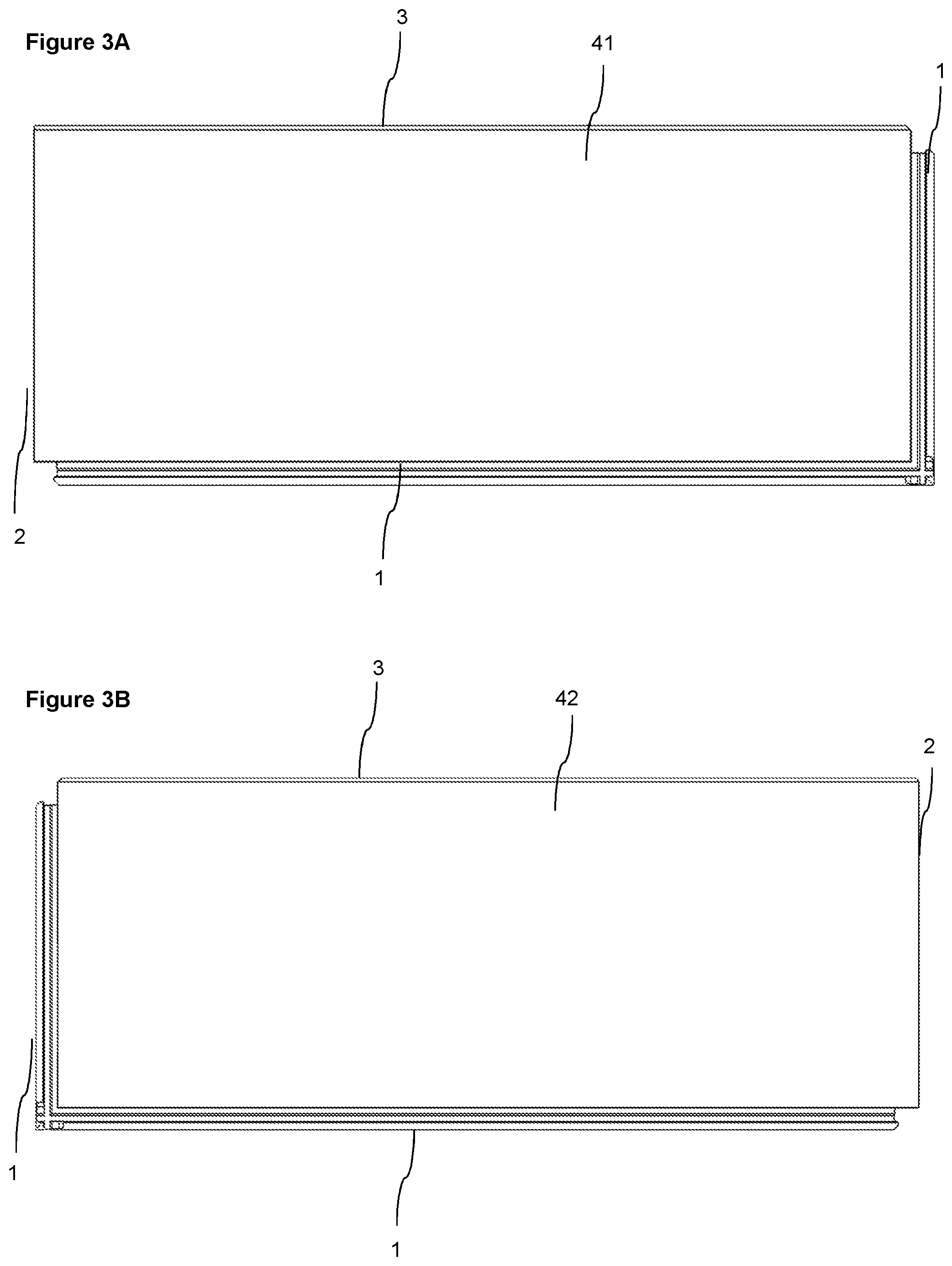
FIG. 3B shows an embodiment of a second panel according to the invention, comprising, in a clockwise direction starting from the edge to the right, the second edge, the first edge, the first edge, and the third edge.
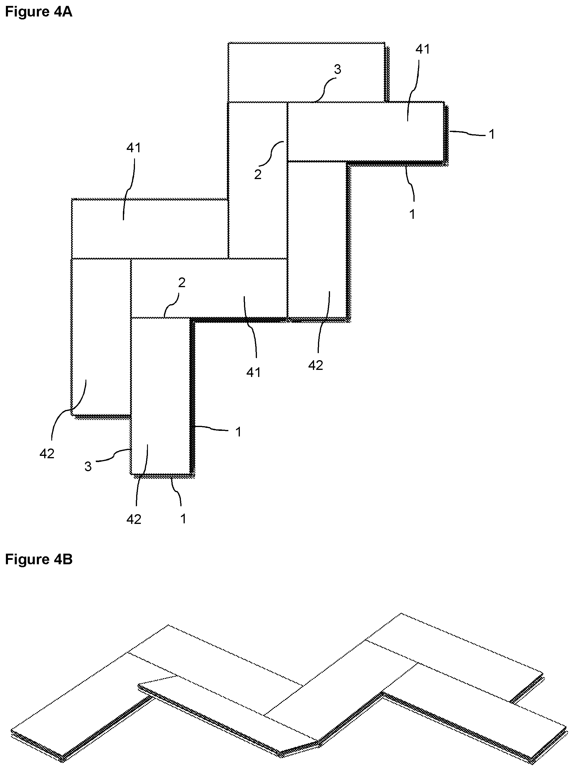
FIGS. 4A-4B show an embodiment of a set of panels according to the present invention, in which the panels are assembled in a herringbone pattern.
FIGS. 5A-5B show an embodiment in which panels according to the present invention are assembled in a modular pattern, i.e., parallel to each other. When assembling the panels in a modular pattern either only multiples of the first panel or only multiples of the second panel are to be connected to each other.
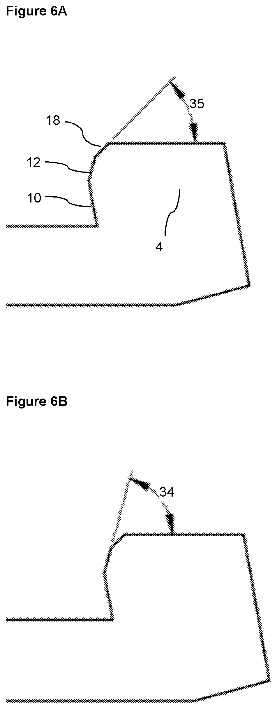
FIGS. 6A-6E show enlargements of the first locking element, illustrating angles between the different surfaces of the first locking element and also angles between the surfaces of the first locking element and an upper surface of the first or second panel.
DETAILED DESCRIPTION
Specific embodiments of the invention will now be described with reference to the accompanying drawings. This invention may, however, be embodied in many different forms and should not be construed as limited to the embodiments set forth herein; rather, these embodiments are provided so that this disclosure will be thorough and complete, and will fully convey the scope of the invention to those skilled in the art. The terminology used in the detailed description of the embodiments illustrated in the accompanying drawings is not intended to limit the invention. In the drawings, like numbers refer to like elements. When the word "about" is used in this specification in connection with a numerical value, it is intended that the associated numerical value include a tolerance of +/-10% around the stated numerical value.
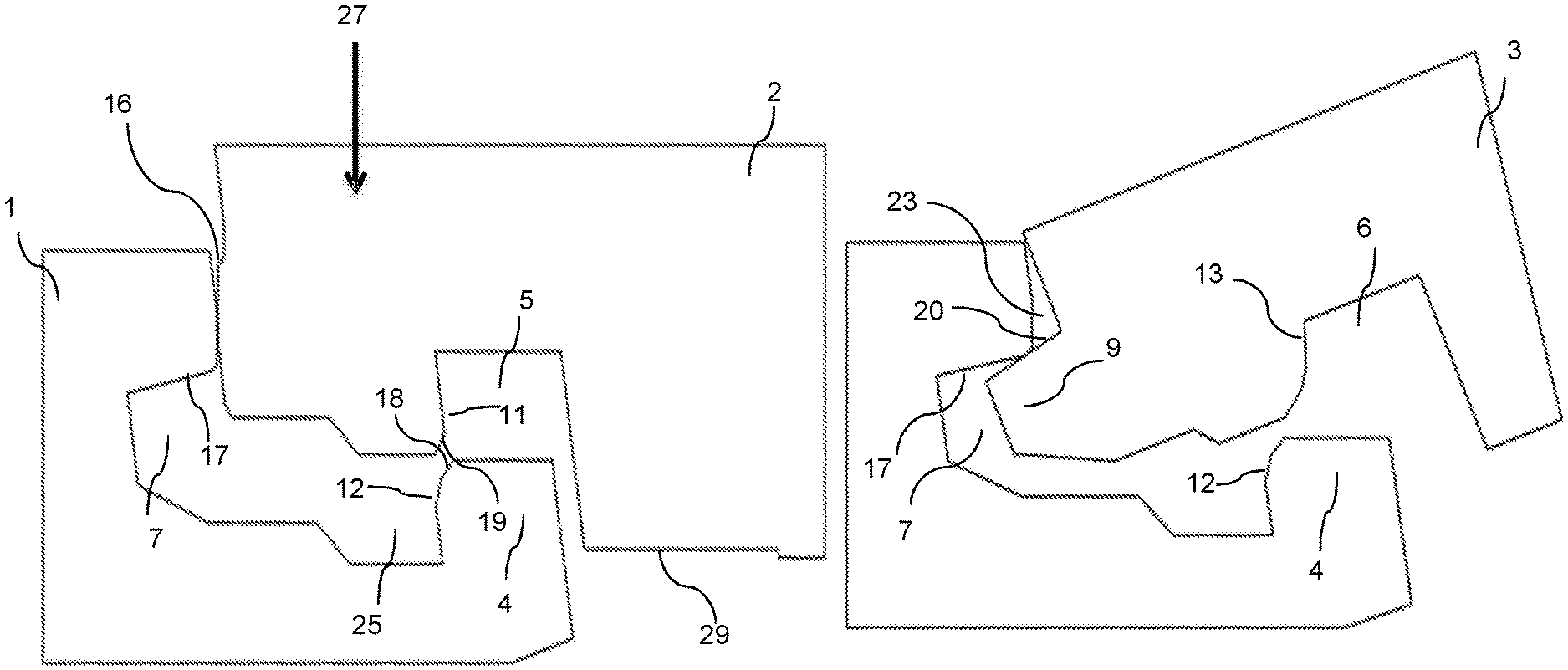
An embodiment of the invention is shown during assembling in FIGS. 1A-1C. The embodiment comprises a set of panels comprising a first panel 41 and a second panel 42, as shown in FIGS. 3A and 3B, wherein a first edge 1 of the first panel 41 and a second edge 2 of the second panel 42 are configured to be locked together and assembled by a vertical displacement 27 of the second edge 2 of the second panel 42 relative to the first edge 1 of the first panel 41.
The first edge 1 comprises a first locking element 4 which is configured to be able to cooperate with a first locking groove 5 at the second edge 2, for locking in a horizontal direction. The first edge 1 also comprises a tongue groove 7 which is configured to cooperate with a tongue 8 at the second edge 2, for locking in a vertical direction. Further, the first locking element 4 comprises a first locking surface 10 which is configured to cooperate with a second locking surface 11 on the first locking groove 5, for locking in the horizontal and the vertical direction.
The first locking surface 10 may be parallel or essentially parallel to the second locking surface 11.
A first guiding surface 14 may be comprised on an upper part of the first edge 1, which first guiding surface 14 cooperates with a second guiding surface 15 on the lower edge of the tongue 8 during the vertical displacement 27.
The tongue 8 on the second edge 2 may comprise an upper locking surface 16 which is configured to cooperate for locking in a vertical direction with a lower locking surface 17 of an upper lip 26 of the tongue groove 7.
The locking element 4 may comprise a third guiding surface 18 and the locking groove 5 may comprise a fourth guiding surface 19. These features are configured to cooperate during the vertical displacement 27 of the second edge 2 relative to the first edge 1 for assembling the second edge 2 to the first edge 1, as shown in FIG. 1B.
The first guiding surface 14 may be parallel or essentially parallel to the second guiding surface 15.
The third guiding surface 18 may be parallel or essentially parallel to the fourth guiding surface 19.
The first and the second guiding surfaces 14,15 are configured to cooperate before the third and fourth guiding surfaces 18,19 during the vertical displacement.
The second edge 2 may comprise a second locking element 22 and the first edge 1 may comprise a third locking groove 25 which are configured to cooperate for locking in a horizontal direction.
The upper locking surface 16 is positioned above the second guiding surface 15.
The first locking surface 10 is positioned below the third guiding surface 18.
A locked position of the first edge 1 and the second edge 2 is shown in FIG. 1C. The first 1 and second edge 2 may be assembled by the vertical displacement 27.
The second edge 2 may include a lower groove 29 on the underside of the second edge 2. This lower groove 29 may provide a space to allow the second edge 2 to bend in order to allow the upper locking surface 16 and the lower locking surface 17 to lock together with greater ease.
The length of the second edge 2 is preferably shorter than the length of the first edge 1.
The vertical and horizontal lockings may be an advantage, especially for panels with a locking in a resilient material. The multiple vertical lockings may decrease the risk of unlocking and a separation of the first 1 and second 2 edges.
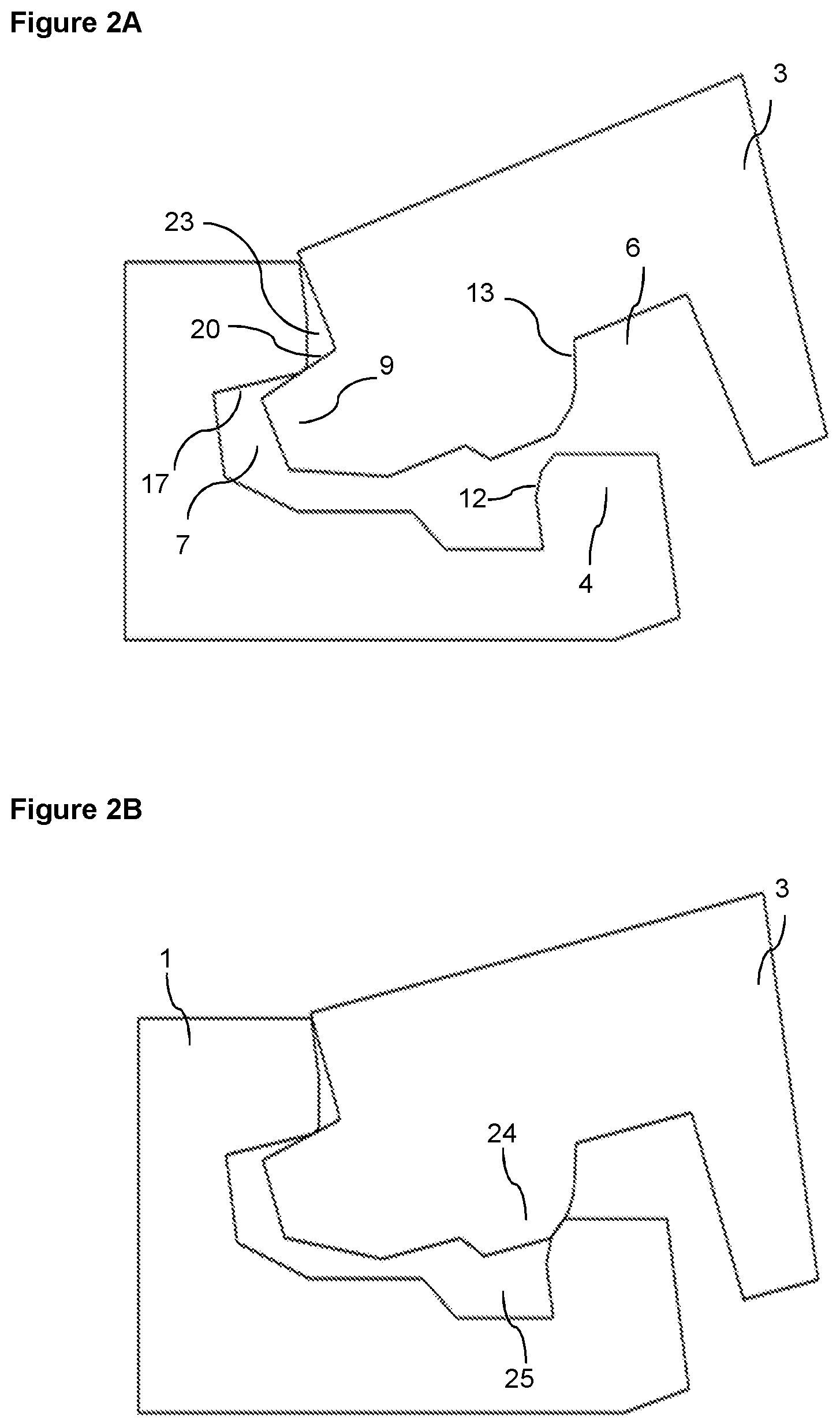
An embodiment of the invention is shown during assembling in FIGS. 2A-2C. The embodiment comprises a set of panels comprising a first panel 41 and a second panel 42, wherein a first edge 1 of the first panel 41 and a third edge 3 of the second panel 42 are configured to be locked together and assembled by an angling motion of the third edge 3 of the second panel 42 relative to the first edge 1 of the first panel 41.
The first edge 1 comprises a first locking element 4 which is configured to be able to cooperate with a second locking groove 6 at the third edge 3, for locking in a horizontal direction.
The first edge 1 also comprises a tongue groove 7 which is configured to cooperate with a tongue 9 at the third edge 3, for locking in a vertical direction. Further, the first locking element 4 comprises a third locking surface 12 which is configured to cooperate with a fourth locking surface 13 on the second locking groove 6, for locking in the horizontal direction.
The third locking surface 12 may be parallel or essentially parallel to the fourth locking surface 13.
The tongue 9 may comprise an upper locking surface 20 which is configured to cooperate for locking in a vertical direction with the lower locking surface 17 of the upper lip 26 of the tongue groove 7.
The third edge 3 may comprise a third locking element 24 configured to cooperate with a third locking groove 25 on the first edge 1 for locking in a horizontal direction.
The third edge 3 may be assembled to the first edge 1 by an angling motion, which is shown in FIGS. 2A and 2B.
The horizontal lockings as specified above may be an advantage, especially for panels with a locking in a resilient material. The multiple horizontal lockings may decrease the risk of unlocking and a separation of the first 1 and third 3 edges.
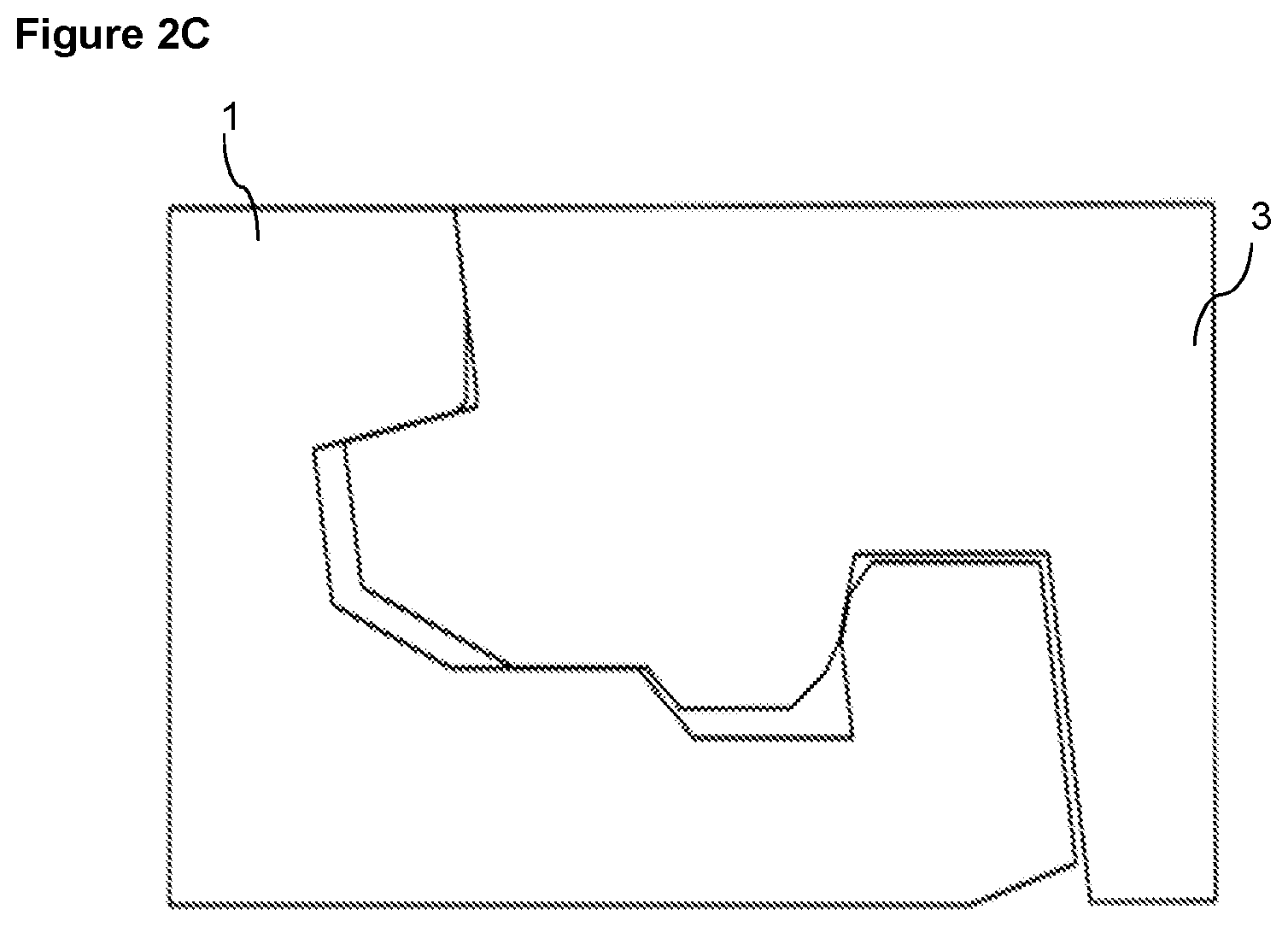
A locked position of the first edge 1 and the third edge 3 is shown in FIG. 2C.
The first locking surface 10 is positioned below the third locking surface 12.
The third locking surface 12 is positioned below the third guiding surface 18.
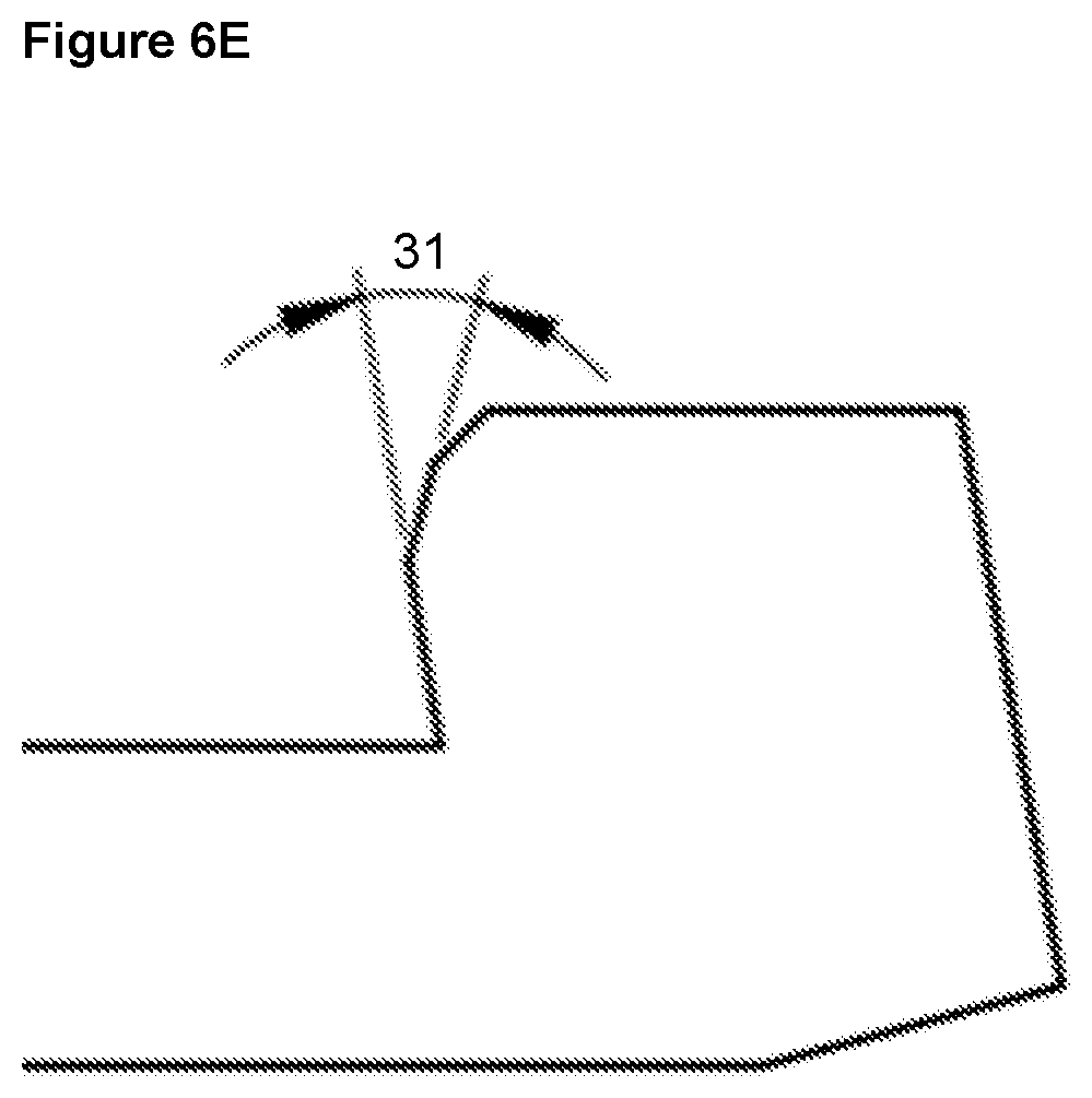
Enlargements of the first locking element 4 are shown in FIGS. 6A-6E.
An angle 31 between the first 10 and third 12 locking surface may be within the range of about 5.degree. to about 30.degree., preferably within the range of about 10.degree. to about 25.degree., or preferably about 17.degree..
An angle 32 between the third locking surface 12 and third guiding surface 18 may be within the range of about 10.degree. to about 40.degree., preferably within the range of about 20.degree. to about 30.degree., or preferably about 25.degree..
An angle 33 between the first locking surface 10 and an upper surface of the first 41 or second 42 panel may be within the range of about 70.degree. to about 85.degree., preferably within the range of about 75.degree. to about 80.degree., or preferably about 77.degree..
An angle 34 between the third locking surface 12 and an upper surface of the first 41 or second 42 panel may be within the range of about 50.degree. to about 85.degree., preferably within the range of about 60.degree. to about 75.degree., or preferably about 67.degree..
An angle 35 between the third guiding surface 18 and an upper surface of the first 41 or second 42 panel may be within the range of about 25.degree. to about 60.degree., preferably within the range of about 35.degree. to about 50.degree., or preferably about 42.degree..
The set of panels according to embodiments of the present invention may provide an increased locking strength of the panels due to the multiple locking surfaces. An improved locking together of the panels may be critical for keeping the panels in position, also when being subject to forces by subject matter in motion on the panels.
The set of panels according to embodiments of the present invention may also be easier to assemble compared to known sets of panels due to the guiding surfaces. An improved guiding may be critical for assembling panels having surfaces with a high friction and particularly, if the panel edges comprise a less elastic material. Without the improved guiding such panels may be difficult to assemble or the panels or part of the panel, e.g., the tongue may break during the assembling. The set of panels according to embodiments of the present invention also provide a more compact junction between panels and thereby a reduced amount of panel material going to waste.
The set of panels according to embodiments of the present invention may be assembled in different patterns. One example is a herringbone pattern, wherein a first 41 and second 42 panel are assembled, as shown in FIGS. 4A-4B. When assembling the panels in a herringbone pattern, the second edge 2 of the second panel 42 is to be connected vertically to the first edge 1 of the first panel 41.
Another example is a modular pattern, in which the panels are assembled parallel to each other, as shown in FIGS. 5A-5B. When assembling the panels in a modular pattern either only multiples of the first panel 41 or only multiples of the second panel 42 are to be connected to each other in each row of panels. When assembling the panels in a modular pattern, the first edge 1 of a first panel 41 is connected to the third edge 3 of a first panel 41, or, alternatively, the first edge 1 of a second panel 42 is connected to the third edge 3 of a second panel 42.
The first panel 41 may comprise, in a clockwise direction, the first edge 1, the first edge 1, the second edge 2, and the third edge 3, as shown in FIG. 3A.
The second panel 42 may comprise, in a clockwise direction, the second edge 2, the first edge 1, the first edge 1, and the third edge 3, as shown in FIG. 3B.
The first 41 panel and the second 42 panel may have a thickness in the range of about 3 mm to about 12 mm.
The embodiments described above may be resilient panels. The resilient panels may comprise a core comprising thermoplastic material. The thermoplastic material may be foamed.
The thermoplastic material may comprise polyvinyl chloride (PVC), polyester, polypropylene (PP), polyethylene (PE), polystyrene (PS), polyurethane (PU), polyethylene terephthalate (PET), polyacrylate, methacrylate, polycarbonate, polyvinyl butyral, polybutylene terephthalate, or a combination thereof. The core may be formed of several layers.
The embodiments described above may comprise a decorative layer, such as a decorative foil comprising a thermoplastic material. The thermoplastic material of the decorative layer may be or comprise polyvinyl chloride (PVC), polyester, polypropylene (PP), polyethylene (PE), polystyrene (PS), polyurethane (PU), polyethylene terephthalate (PET), polyacrylate, methacrylate, polycarbonate, polyvinyl butyral, polybutylene terephthalate, or a combination thereof. The decorative foil is preferably printed, for example by direct printing, rotogravure, or digital printing.
The embodiments described above may comprise a wear layer such as a film or foil. The wear layer may comprise thermoplastic material. The thermoplastic material may be polyvinyl chloride (PVC), polyester, polypropylene (PP), polyethylene (PE), polystyrene (PS), polyurethane (PU), polyethylene terephthalate (PET), polyacrylate, methacrylate, polycarbonate, polyvinyl butyral, polybutylene terephthalate, or a combination thereof.
The embodiments described above may comprise a wood base core, such as HDF, MDF or plywood.
The first panel and the second panel may be configured to be disassembled by downwardly rotating the first and/or the second panel.
EMBODIMENTS
1. A set of panels comprising a first panel (41) and a second panel (42), said first (41) and second (42) panel each having a first edge (1), a second edge (2) and a third (3) edge and wherein the first edge (1) of the first panel (41) is configured to be able to be locked together with both the second (2) edge and the third (3) edge, respectively, of the second panel (42), wherein the first edge (1) comprises a first locking element (4) configured to be able to cooperate with a first locking groove (5) at the second edge (2) and a second locking groove (6) at the third edge (3), respectively, for locking in a horizontal direction, wherein the first edge (1) further comprises a tongue groove (7) configured to cooperate with a tongue (8) at the second edge (2) and a tongue (9) at the third edge (3), respectively, for locking in a vertical direction, wherein the first locking element (4) comprises a first locking surface (10) configured to cooperate with a second locking surface (11) on the first locking groove (5), for locking in the horizontal and the vertical direction, and wherein the first locking element (4) comprises a third locking surface (12) which is configured to cooperate with a fourth locking surface (13) on the second locking groove (6) for locking in the horizontal direction.
2. The set of panels according to embodiment 1, wherein an upper part of the first edge (1) comprises a first guiding surface (14) and a lower edge of the tongue (8) of the second edge (2) comprises a second guiding surface (15), configured to cooperate during a vertical displacement (27) of the second edge (2) relative the first edge (1) for assembling the second edge (2) to the first edge (1).
3. The set of panels according to embodiment 1 or 2, wherein the tongue (8) on the second edge (2) comprises an upper locking surface (16) which is configured to cooperate for locking in a vertical direction with a lower locking surface (17) of an upper lip (26) of the tongue groove (7).
4. The set of panels according to any of the embodiments 1 to 3, wherein an upper part of the first locking element (4) comprises a third guiding surface (18) and a lower edge of the first locking groove (5) comprises a fourth guiding surface (19), configured to cooperate during the vertical displacement (27) of the second edge (2) relative to the first edge (1) for assembling the second edge (2) to the first edge (1).
5. The set of panels according to any one of the embodiments 1 to 4, wherein the tongue (9) comprises an upper locking surface (20) which is configured to cooperate for locking in a vertical direction with the lower locking surface (17) of the upper lip (26) of the tongue groove (7).
6. The set of panels according to any one of the embodiments 1 to 5, wherein an angle (31) between the first (10) and third (12) locking surface is within the range of about 5.degree. to about 30.degree., preferably within the range of about 10.degree. to about 25.degree., or preferably about 17.degree..
7. The set of panels according to any one of the embodiments 4 to 6, wherein an angle (32) between the third locking surface (12) and third guiding surface (18) is within the range of about 10.degree. to about 40.degree., preferably within the range of about 20.degree. to about 30.degree., or preferably about 25.degree..
8. The set of panels according to any one of the previous embodiments, wherein the second edge (2) comprises a second locking element (22) and the first edge (1) comprises a third locking groove (25), and wherein the second locking element and the third locking groove are configured to cooperate for locking in a horizontal direction.
9. The set of panels according to any one of the previous embodiments, wherein the third edge (3) comprises a third locking element (24) configured to cooperate with the third locking groove (25) for locking in a horizontal direction.
10. The set of panels according to any one of the previous embodiments, wherein the length of the second edge (2) is shorter than the length of the first edge (1).
11. The set of panels according to any one of the previous embodiments, wherein the second edge (2) of the second panel (42) is to be connected vertically to the first edge (1) of the first panel (41).
12. The set of panels according to any one of the previous embodiments, wherein the first panel (41) comprises, in a clockwise direction, the first edge (1), the first edge (1), the second edge (2), and the third edge (3).
13. The set of panels according to any one of the previous embodiments, wherein the second panel (42) comprises, in a clockwise direction, the second edge (2), the first edge (1), the first edge (1), and the third edge (3).
14. The set of panels according to any one of the previous embodiments, wherein the third edge (3) is configured to be assembled to the first edge (1) by an angling motion.
* * * * *
D00000
D00001
D00002
D00003
D00004
D00005
D00006
D00007
D00008
D00009
D00010
XML
uspto.report is an independent third-party trademark research tool that is not affiliated, endorsed, or sponsored by the United States Patent and Trademark Office (USPTO) or any other governmental organization. The information provided by uspto.report is based on publicly available data at the time of writing and is intended for informational purposes only.
While we strive to provide accurate and up-to-date information, we do not guarantee the accuracy, completeness, reliability, or suitability of the information displayed on this site. The use of this site is at your own risk. Any reliance you place on such information is therefore strictly at your own risk.
All official trademark data, including owner information, should be verified by visiting the official USPTO website at www.uspto.gov. This site is not intended to replace professional legal advice and should not be used as a substitute for consulting with a legal professional who is knowledgeable about trademark law.