Method to produce a thermoplastic wear resistant foil
Lundblad , et al. De
U.S. patent number 10,493,731 [Application Number 14/790,850] was granted by the patent office on 2019-12-03 for method to produce a thermoplastic wear resistant foil. This patent grant is currently assigned to VALINGE INNOVATION AB. The grantee listed for this patent is VALINGE INNOVATION AB. Invention is credited to Niclas Hakansson, Christer Lundblad, Goran Ziegler.
| United States Patent | 10,493,731 |
| Lundblad , et al. | December 3, 2019 |
Method to produce a thermoplastic wear resistant foil
Abstract
A method to produce a wear resistant foil, including providing a first foil including a first thermoplastic material, applying wear resistant particles and a second thermoplastic material form on the first foil, and adhering the first foil to the second thermoplastic binder and the wear resistant particles to form a wear resistant foil.
| Inventors: | Lundblad; Christer (Orkelljunga, SE), Hakansson; Niclas (Viken, SE), Ziegler; Goran (Viken, SE) | ||||||||||
|---|---|---|---|---|---|---|---|---|---|---|---|
| Applicant: |
|
||||||||||
| Assignee: | VALINGE INNOVATION AB (Viken,
SE) |
||||||||||
| Family ID: | 55073860 | ||||||||||
| Appl. No.: | 14/790,850 | ||||||||||
| Filed: | July 2, 2015 |
Prior Publication Data
| Document Identifier | Publication Date | |
|---|---|---|
| US 20160016391 A1 | Jan 21, 2016 | |
Foreign Application Priority Data
| Jul 16, 2014 [SE] | 1450894 | |||
| Jul 16, 2014 [SE] | 1450895 | |||
| Apr 16, 2015 [SE] | 1550455 | |||
| Current U.S. Class: | 1/1 |
| Current CPC Class: | B32B 33/00 (20130101); B32B 37/24 (20130101); B32B 37/14 (20130101); B32B 19/045 (20130101); B32B 27/08 (20130101); E04F 15/107 (20130101); B32B 27/32 (20130101); B32B 21/08 (20130101); B32B 27/22 (20130101); B32B 21/12 (20130101); B32B 27/36 (20130101); B32B 27/40 (20130101); B32B 5/18 (20130101); B32B 37/10 (20130101); B32B 27/365 (20130101); B32B 27/304 (20130101); B32B 5/16 (20130101); B32B 21/02 (20130101); B32B 19/048 (20130101); B32B 27/065 (20130101); B32B 27/20 (20130101); E04F 15/105 (20130101); B32B 27/14 (20130101); B32B 2264/02 (20130101); B32B 2264/067 (20130101); B32B 2250/24 (20130101); B32B 37/223 (20130101); B32B 2307/584 (20130101); B32B 2264/102 (20130101); B32B 2264/12 (20130101); B32B 37/153 (20130101); B32B 37/12 (20130101); B32B 2250/02 (20130101); B32B 2317/16 (20130101); B32B 2307/412 (20130101); B32B 2270/00 (20130101); B32B 2264/10 (20130101); B32B 2419/00 (20130101); B32B 2419/04 (20130101); B32B 2471/00 (20130101); B32B 2309/105 (20130101); B32B 2264/101 (20130101); B32B 38/145 (20130101); B32B 2264/107 (20130101); B32B 37/1027 (20130101); B32B 38/06 (20130101); B32B 2250/246 (20130101); B29K 2075/00 (20130101); B29K 2627/06 (20130101); B32B 2307/744 (20130101); B29C 48/15 (20190201); B32B 2307/554 (20130101); B32B 2250/40 (20130101) |
| Current International Class: | B32B 37/24 (20060101); B32B 27/32 (20060101); B32B 27/36 (20060101); B32B 5/16 (20060101); B32B 37/10 (20060101); B32B 33/00 (20060101); B32B 5/18 (20060101); B32B 27/14 (20060101); B32B 27/22 (20060101); B32B 27/30 (20060101); B32B 37/14 (20060101); B05D 3/12 (20060101); B05D 7/06 (20060101); B32B 27/08 (20060101); B32B 27/06 (20060101); B32B 27/40 (20060101); B32B 27/20 (20060101); B32B 38/00 (20060101); B32B 38/06 (20060101); B32B 37/22 (20060101); B32B 37/15 (20060101); B32B 37/12 (20060101); B29C 48/15 (20190101) |
References Cited [Referenced By]
U.S. Patent Documents
| 213740 | April 1879 | Connor |
| 1018987 | February 1912 | Philpot et al. |
| 1361501 | December 1920 | Schepmoes |
| 1394120 | October 1921 | Rockwell |
| 1723306 | August 1929 | Sipe |
| 1743492 | January 1930 | Sipe |
| 1787027 | December 1930 | Wasleff |
| 1925070 | August 1933 | Livezey |
| 1946646 | February 1934 | Storm |
| 1946690 | February 1934 | Haines |
| 2015813 | October 1935 | Nielsen |
| 2088238 | July 1937 | Greenway |
| 2089075 | August 1937 | Siebs |
| 2142305 | January 1939 | Davis |
| 2204675 | June 1940 | Grunert |
| 2266464 | December 1941 | Kraft |
| 2303745 | December 1942 | Karreman |
| 2306295 | December 1942 | Casto |
| 2355834 | August 1944 | Webb |
| 2497837 | February 1950 | Nelson |
| 2740167 | April 1956 | Rowley |
| 2769726 | November 1956 | Wetterau et al. |
| 2818895 | January 1958 | Zuber |
| 2861372 | November 1958 | Hunt |
| 2872712 | February 1959 | Brown |
| 2947040 | August 1960 | Schultz |
| 3055461 | September 1962 | De Ridder |
| 3087269 | April 1963 | Hudson |
| 3120083 | February 1964 | Dahlberg et al. |
| 3135643 | June 1964 | Michl |
| 3247638 | April 1966 | Gay et al. |
| 3259417 | July 1966 | Chapman |
| 3286006 | November 1966 | Annand |
| 3308013 | March 1967 | Bryant |
| 3310919 | March 1967 | Bue et al. |
| 3397496 | August 1968 | Sohns |
| 3436888 | April 1969 | Ottosson |
| 3538665 | November 1970 | Gohner |
| 3554850 | January 1971 | Kuhle |
| 3578548 | May 1971 | Wesp |
| 3619963 | November 1971 | Omholt |
| 3623288 | November 1971 | Horowitz |
| 3657852 | April 1972 | Worthington et al. |
| 3694983 | October 1972 | Couquet |
| 3760547 | September 1973 | Brenneman |
| 3857749 | December 1974 | Yoshida |
| 3883258 | May 1975 | Hewson |
| 3887678 | June 1975 | Lewicki, Jr. |
| 3908725 | September 1975 | Koch |
| 3937861 | February 1976 | Zuckerman et al. |
| 3946529 | March 1976 | Chevaux |
| 3950915 | April 1976 | Cole |
| 4023596 | May 1977 | Tate |
| 4037377 | July 1977 | Howell et al. |
| 4092198 | May 1978 | Scher |
| 4093766 | June 1978 | Scher |
| 4100710 | July 1978 | Kowallik |
| 4169688 | October 1979 | Toshio |
| 4170859 | October 1979 | Counihan |
| 4176210 | November 1979 | Skinner |
| 4226064 | October 1980 | Kraayenhof |
| 4242390 | December 1980 | Nemeth |
| 4255480 | March 1981 | Scher |
| 4256793 | March 1981 | Cannady, Jr. et al. |
| 4296017 | October 1981 | Weissgerber et al. |
| 4299070 | November 1981 | Oltmanns et al. |
| 4312686 | January 1982 | Smith et al. |
| 4315724 | February 1982 | Taoka et al. |
| 4376147 | March 1983 | Byrne et al. |
| 4396566 | August 1983 | Brinkmann et al. |
| 4426820 | January 1984 | Terbrack et al. |
| 4430375 | February 1984 | Scher |
| 4450194 | May 1984 | Kauffman et al. |
| 4454699 | June 1984 | Strobl |
| 4489115 | December 1984 | Layman et al. |
| 4512131 | April 1985 | Laramore |
| 4526418 | July 1985 | Martin |
| 4570353 | February 1986 | Evans |
| 4574099 | March 1986 | Nixon |
| 4599841 | July 1986 | Haid |
| 4610900 | September 1986 | Nishibori |
| 4615090 | October 1986 | Baus |
| 4724187 | February 1988 | Ungar et al. |
| 4756856 | July 1988 | Choinski |
| 4759164 | July 1988 | Abendroth et al. |
| 4769963 | September 1988 | Meyerson |
| 4788088 | November 1988 | Kohl |
| 4807412 | February 1989 | Frederiksen |
| 4849768 | July 1989 | Graham |
| 4916007 | April 1990 | Manning et al. |
| 4944514 | July 1990 | Suiter |
| 4947595 | August 1990 | Douds et al. |
| 4976221 | December 1990 | Yetter |
| 5007222 | April 1991 | Raymond |
| 5050362 | September 1991 | Tal et al. |
| 5052158 | October 1991 | D'Luzansky |
| 5076034 | December 1991 | Bandy |
| 5112671 | May 1992 | Diamond et al. |
| 5134026 | July 1992 | Melcher |
| 5162141 | November 1992 | Davey et al. |
| 5185193 | February 1993 | Phenicie et al. |
| 5188876 | February 1993 | Hensel et al. |
| 5229217 | July 1993 | Holzer |
| 5266384 | November 1993 | O'Dell |
| 5295341 | March 1994 | Kajiwara |
| 5322335 | June 1994 | Niemi |
| 5333429 | August 1994 | Cretti |
| 5349796 | September 1994 | Meyerson |
| 5367844 | November 1994 | Diedrich |
| 5433806 | July 1995 | Pasquali et al. |
| 5466511 | November 1995 | O'Dell et al. |
| 5480602 | January 1996 | Nagaich |
| 5502939 | April 1996 | Zadok |
| 5503788 | April 1996 | Lazareck et al. |
| 5516472 | May 1996 | Laver |
| 5543193 | August 1996 | Tesch |
| 5547741 | August 1996 | Wilson |
| 5553427 | September 1996 | Andres |
| 5604025 | February 1997 | Tesch |
| 5613339 | March 1997 | Pollock |
| 5618602 | April 1997 | Nelson |
| 5642592 | July 1997 | Andres |
| 5647184 | July 1997 | Davis |
| 5653099 | August 1997 | MacKenzie |
| 5660016 | August 1997 | Erwin et al. |
| 5662977 | September 1997 | Spain et al. |
| 5670237 | September 1997 | Shultz et al. |
| 5671575 | September 1997 | Wu |
| 5694730 | December 1997 | Del Rincon et al. |
| 5706621 | January 1998 | Pervan |
| 5713165 | February 1998 | Erwin |
| 5724909 | March 1998 | Pitman et al. |
| 5728476 | March 1998 | Harwood |
| 5755068 | May 1998 | Ormiston |
| 5758466 | June 1998 | Tucker |
| 5766522 | June 1998 | Daly et al. |
| 5777014 | July 1998 | Hopper et al. |
| 5780147 | July 1998 | Sugahara et al. |
| 5787655 | August 1998 | Saylor, Jr. |
| 5791113 | August 1998 | Glowa et al. |
| 5797237 | August 1998 | Finkell, Jr. |
| 5833386 | November 1998 | Rosan et al. |
| 5836128 | November 1998 | Groh et al. |
| 5855832 | January 1999 | Clausi |
| 5856389 | January 1999 | Kostrzewski et al. |
| 5858160 | January 1999 | Piacente |
| 5863632 | January 1999 | Bisker |
| 5869138 | February 1999 | Nishibori |
| D406360 | March 1999 | Finkell, Jr. |
| 5900099 | May 1999 | Sweet |
| 5989668 | November 1999 | Nelson et al. |
| 6004417 | December 1999 | Roesch et al. |
| 6006486 | December 1999 | Moriau |
| 6013222 | January 2000 | Douglas et al. |
| 6023907 | February 2000 | Pervan |
| 6027599 | February 2000 | Wang |
| 6029416 | February 2000 | Anderson |
| 6093473 | July 2000 | Min |
| 6101778 | August 2000 | Martensson |
| 6103377 | August 2000 | Clausi |
| 6139945 | October 2000 | Krejchi et al. |
| 6173548 | January 2001 | Hamar et al. |
| 6189282 | February 2001 | Vanderwerf |
| 6218001 | April 2001 | Chen |
| 6233899 | May 2001 | Mellert et al. |
| 6260326 | July 2001 | Muller-Hartburg |
| 6314701 | November 2001 | Meyerson |
| 6324809 | December 2001 | Nelson |
| 6332733 | December 2001 | Hamberger et al. |
| 6345481 | February 2002 | Nelson |
| 6363677 | April 2002 | Chen |
| 6397547 | June 2002 | Martensson |
| 6423167 | July 2002 | Palmer et al. |
| 6428871 | August 2002 | Cozzolino |
| 6438919 | August 2002 | Knauseder |
| 6444075 | September 2002 | Schneider et al. |
| 6455127 | September 2002 | Valtanen |
| 6460306 | October 2002 | Nelson |
| 6468645 | October 2002 | Clausi |
| 6505452 | January 2003 | Hannig |
| 6536178 | March 2003 | Palsson et al. |
| 6546691 | April 2003 | Leopolder |
| 6558070 | May 2003 | Valtanen |
| 6579610 | June 2003 | Shortland |
| 6591568 | July 2003 | Palsson et al. |
| 6617009 | September 2003 | Chen et al. |
| 6647690 | November 2003 | Martensson |
| 6666951 | December 2003 | Kostiw |
| 6671968 | January 2004 | Shannon |
| 6672030 | January 2004 | Schulte |
| 6675545 | January 2004 | Chen et al. |
| 6695944 | February 2004 | Courtney |
| 6711869 | March 2004 | Tychsen |
| 6715253 | April 2004 | Pervan |
| 6729091 | May 2004 | Martensson |
| 6761008 | July 2004 | Chen et al. |
| 6766622 | July 2004 | Thiers |
| 6769218 | August 2004 | Pervan |
| 6769219 | August 2004 | Schwitte et al. |
| 6786019 | September 2004 | Thiers |
| 6803110 | October 2004 | Drees et al. |
| 6804926 | October 2004 | Eisermann |
| 6835421 | December 2004 | Dohring |
| 6851237 | February 2005 | Niese et al. |
| 6854235 | February 2005 | Martensson |
| 6862857 | March 2005 | Tychsen |
| 6874292 | April 2005 | Moriau |
| 6880305 | April 2005 | Pervan et al. |
| 6880307 | April 2005 | Schwitte |
| 6895881 | May 2005 | Whitaker |
| 6898911 | May 2005 | Kornfalt et al. |
| 6898913 | May 2005 | Pervan |
| 6918220 | July 2005 | Pervan |
| 6922964 | August 2005 | Pervan |
| 6922965 | August 2005 | Rosenthal et al. |
| 6926954 | August 2005 | Schuren et al. |
| 6933043 | August 2005 | Son et al. |
| 6955020 | October 2005 | Moriau et al. |
| 6966963 | November 2005 | O'Connor |
| 6986934 | January 2006 | Chen et al. |
| 7051486 | May 2006 | Pervan |
| 7086205 | August 2006 | Pervan |
| 7090430 | August 2006 | Fletcher |
| D528671 | September 2006 | Grafenauer |
| 7121058 | October 2006 | Palsson et al. |
| 7127860 | October 2006 | Pervan et al. |
| 7137229 | November 2006 | Pervan |
| 7155871 | January 2007 | Stone |
| 7169460 | January 2007 | Chen et al. |
| 7171791 | February 2007 | Pervan |
| 7211310 | May 2007 | Chen et al. |
| 7261947 | August 2007 | Reichwein |
| 7275350 | October 2007 | Pervan et al. |
| 7276265 | October 2007 | Sigel et al. |
| 7328536 | February 2008 | Moriau et al. |
| 7337588 | March 2008 | Moebus |
| 7356971 | April 2008 | Pervan |
| 7386963 | June 2008 | Pervan |
| 7398625 | July 2008 | Pervan |
| 7419717 | September 2008 | Chen et al. |
| 7454875 | November 2008 | Pervan et al. |
| 7516588 | April 2009 | Pervan |
| 7543418 | June 2009 | Weitzer |
| 7544423 | June 2009 | Horton |
| 7568322 | August 2009 | Pervan et al. |
| 7576140 | August 2009 | Tamaki et al. |
| 7584583 | September 2009 | Bergelin et al. |
| 7603826 | October 2009 | Moebus |
| 7739849 | June 2010 | Pervan |
| 7763345 | July 2010 | Chen et al. |
| 7770350 | August 2010 | Moriau et al. |
| 7779597 | August 2010 | Thiers et al. |
| 7802415 | September 2010 | Pervan |
| 7816000 | October 2010 | Sparks et al. |
| 7856784 | December 2010 | Martensson |
| 7856789 | December 2010 | Eisermann |
| 7866115 | January 2011 | Pervan et al. |
| 7877956 | February 2011 | Martensson |
| 7886497 | February 2011 | Pervan et al. |
| 7896571 | March 2011 | Hannig et al. |
| 7926234 | April 2011 | Pervan |
| 7930862 | April 2011 | Bergelin et al. |
| 7958689 | June 2011 | Lei |
| 7980043 | July 2011 | Moebus |
| 7984600 | July 2011 | Alford et al. |
| 8021741 | September 2011 | Chen et al. |
| 8028486 | October 2011 | Pervan |
| 8043661 | October 2011 | Linnemann |
| 8071193 | December 2011 | Windmoller |
| 8099919 | January 2012 | Garcia |
| 8112891 | February 2012 | Pervan |
| 8166718 | May 2012 | Liu |
| 8171691 | May 2012 | Stone |
| 8182928 | May 2012 | Horton |
| 8234829 | August 2012 | Thiers et al. |
| 8245478 | August 2012 | Bergelin et al. |
| 8293058 | October 2012 | Pervan et al. |
| 8356452 | January 2013 | Thiers et al. |
| 8365499 | February 2013 | Nilsson et al. |
| 8375674 | February 2013 | Braun |
| 8431054 | April 2013 | Pervan |
| 8480841 | July 2013 | Pervan et al. |
| 8484924 | July 2013 | Braun |
| 8490361 | July 2013 | Curry et al. |
| 8511031 | August 2013 | Bergelin et al. |
| 8544231 | October 2013 | Hannig |
| 8584423 | November 2013 | Pervan et al. |
| 8613826 | December 2013 | Pervan et al. |
| 8658274 | February 2014 | Chen et al. |
| 8683698 | April 2014 | Pervan et al. |
| 8756899 | June 2014 | Nilsson et al. |
| 8800150 | August 2014 | Pervan |
| 8833028 | September 2014 | Whispell et al. |
| 8834992 | September 2014 | Chen et al. |
| 8875465 | November 2014 | Martensson |
| 8973270 | March 2015 | Siebert et al. |
| 9156233 | October 2015 | Dossche et al. |
| 9194133 | November 2015 | Thiers |
| 9200460 | December 2015 | Cappelle |
| 9222267 | December 2015 | Bergelin et al. |
| 9249581 | February 2016 | Nilsson et al. |
| 9296191 | March 2016 | Pervan et al. |
| 9314936 | April 2016 | Pervan |
| 9410328 | August 2016 | Pervan |
| 9670371 | June 2017 | Pervan et al. |
| 9695601 | July 2017 | Whispell et al. |
| 9714515 | July 2017 | Pervan |
| 9765530 | September 2017 | Bergelin et al. |
| 10047527 | August 2018 | Nilsson et al. |
| 10059084 | August 2018 | Lundblad |
| 10137659 | November 2018 | Pervan |
| 10287777 | May 2019 | Boo et al. |
| 10301830 | May 2019 | Boo |
| 10316526 | June 2019 | Kell |
| 2001/0021431 | September 2001 | Chen |
| 2001/0036557 | November 2001 | Ingrim et al. |
| 2002/0007608 | January 2002 | Pervan |
| 2002/0007609 | January 2002 | Pervan |
| 2002/0023702 | February 2002 | Kettler |
| 2002/0025446 | February 2002 | Chen et al. |
| 2002/0031646 | March 2002 | Chen |
| 2002/0046433 | April 2002 | Sellman et al. |
| 2002/0046527 | April 2002 | Nelson |
| 2002/0056245 | May 2002 | Thiers |
| 2002/0083673 | July 2002 | Kettler et al. |
| 2002/0092263 | July 2002 | Schulte |
| 2002/0095894 | July 2002 | Pervan |
| 2002/0100231 | August 2002 | Miller et al. |
| 2002/0112429 | August 2002 | Niese et al. |
| 2002/0112433 | August 2002 | Pervan |
| 2002/0142135 | October 2002 | Chen et al. |
| 2002/0146568 | October 2002 | Ho et al. |
| 2002/0170257 | November 2002 | McLain et al. |
| 2002/0170258 | November 2002 | Schwitte et al. |
| 2002/0178674 | December 2002 | Pervan |
| 2002/0178681 | December 2002 | Zancai |
| 2002/0189183 | December 2002 | Ricciardelli |
| 2003/0009971 | January 2003 | Palmberg |
| 2003/0024199 | February 2003 | Pervan |
| 2003/0024200 | February 2003 | Moriau et al. |
| 2003/0033777 | February 2003 | Thiers et al. |
| 2003/0055145 | March 2003 | Safta et al. |
| 2003/0059639 | March 2003 | Worsley |
| 2003/0072919 | April 2003 | Watts, Jr. et al. |
| 2003/0101674 | June 2003 | Pervan et al. |
| 2003/0101681 | June 2003 | Tychsen |
| 2003/0154676 | August 2003 | Schwartz |
| 2003/0196397 | October 2003 | Niese et al. |
| 2003/0196405 | October 2003 | Pervan |
| 2004/0003888 | January 2004 | Mott et al. |
| 2004/0016196 | January 2004 | Pervan |
| 2004/0031227 | February 2004 | Knauseder |
| 2004/0035078 | February 2004 | Pervan |
| 2004/0048044 | March 2004 | Schneider |
| 2004/0068954 | April 2004 | Martensson |
| 2004/0107659 | June 2004 | Glockl |
| 2004/0139678 | July 2004 | Pervan |
| 2004/0177584 | September 2004 | Pervan |
| 2004/0182036 | September 2004 | Sjoberg et al. |
| 2004/0200154 | October 2004 | Hunter |
| 2004/0206036 | October 2004 | Pervan |
| 2004/0211144 | October 2004 | Stanchfield |
| 2004/0241416 | December 2004 | Tian et al. |
| 2004/0248489 | December 2004 | Hutchison et al. |
| 2004/0255538 | December 2004 | Ruhdorfer |
| 2004/0255541 | December 2004 | Thiers et al. |
| 2005/0003160 | January 2005 | Chen et al. |
| 2005/0055943 | March 2005 | Pervan |
| 2005/0107006 | May 2005 | Makino |
| 2005/0136234 | June 2005 | Hak |
| 2005/0138881 | June 2005 | Pervan |
| 2005/0166502 | August 2005 | Pervan |
| 2005/0166516 | August 2005 | Pervan |
| 2005/0193677 | September 2005 | Vogel |
| 2005/0208255 | September 2005 | Pervan |
| 2005/0210810 | September 2005 | Pervan |
| 2005/0268570 | December 2005 | Pervan |
| 2006/0032168 | February 2006 | Thiers |
| 2006/0048474 | March 2006 | Pervan et al. |
| 2006/0075713 | April 2006 | Pervan et al. |
| 2006/0099386 | May 2006 | Smith |
| 2006/0101769 | May 2006 | Pervan et al. |
| 2006/0130421 | June 2006 | Nollet et al. |
| 2006/0144004 | July 2006 | Nollet et al. |
| 2006/0156666 | July 2006 | Caufield |
| 2006/0191861 | August 2006 | Mitterhofer et al. |
| 2006/0196139 | September 2006 | Pervan |
| 2006/0283127 | December 2006 | Pervan |
| 2007/0011981 | January 2007 | Eiserman |
| 2007/0028547 | February 2007 | Grafenauer et al. |
| 2007/0130872 | June 2007 | Goodwin |
| 2007/0166516 | July 2007 | Kim et al. |
| 2007/0175143 | August 2007 | Pervan et al. |
| 2007/0175144 | August 2007 | Hakansson |
| 2007/0175148 | August 2007 | Bergelin et al. |
| 2007/0175156 | August 2007 | Pervan et al. |
| 2007/0196624 | August 2007 | Chen et al. |
| 2008/0000179 | January 2008 | Pervan |
| 2008/0000180 | January 2008 | Pervan |
| 2008/0000182 | January 2008 | Pervan |
| 2008/0000183 | January 2008 | Bergelin et al. |
| 2008/0000186 | January 2008 | Pervan |
| 2008/0000187 | January 2008 | Pervan |
| 2008/0000188 | January 2008 | Pervan |
| 2008/0000189 | January 2008 | Pervan et al. |
| 2008/0000194 | January 2008 | Pervan |
| 2008/0000417 | January 2008 | Pervan et al. |
| 2008/0005989 | January 2008 | Pervan et al. |
| 2008/0005992 | January 2008 | Pervan |
| 2008/0005997 | January 2008 | Pervan |
| 2008/0005998 | January 2008 | Pervan |
| 2008/0005999 | January 2008 | Pervan |
| 2008/0008871 | January 2008 | Pervan |
| 2008/0010924 | January 2008 | Pietruczynik et al. |
| 2008/0010931 | January 2008 | Pervan |
| 2008/0010937 | January 2008 | Pervan |
| 2008/0028707 | February 2008 | Pervan |
| 2008/0028713 | February 2008 | Pervan |
| 2008/0029490 | February 2008 | Martin et al. |
| 2008/0032120 | February 2008 | Braun |
| 2008/0034701 | February 2008 | Pervan |
| 2008/0034708 | February 2008 | Pervan |
| 2008/0041007 | February 2008 | Pervan et al. |
| 2008/0041008 | February 2008 | Pervan |
| 2008/0060308 | March 2008 | Pervan |
| 2008/0063844 | March 2008 | Chen et al. |
| 2008/0066415 | March 2008 | Pervan et al. |
| 2008/0075882 | March 2008 | Hayata |
| 2008/0104921 | May 2008 | Pervan et al. |
| 2008/0110125 | May 2008 | Pervan |
| 2008/0134607 | June 2008 | Pervan et al. |
| 2008/0134613 | June 2008 | Pervan et al. |
| 2008/0134614 | June 2008 | Pervan et al. |
| 2008/0138560 | June 2008 | Windmoller |
| 2008/0172971 | July 2008 | Pervan |
| 2008/0241440 | October 2008 | Bauer |
| 2008/0256890 | October 2008 | Pervan |
| 2008/0261019 | October 2008 | Shen |
| 2008/0263975 | October 2008 | Mead |
| 2008/0311355 | December 2008 | Chen et al. |
| 2009/0049787 | February 2009 | Hannig |
| 2009/0078129 | March 2009 | Cappelle et al. |
| 2009/0120731 | May 2009 | Thompson et al. |
| 2009/0133353 | May 2009 | Pervan et al. |
| 2009/0151290 | June 2009 | Liu |
| 2009/0151866 | June 2009 | Endert |
| 2009/0155612 | June 2009 | Pervan et al. |
| 2009/0193748 | August 2009 | Boo et al. |
| 2009/0208646 | August 2009 | Kreuder et al. |
| 2009/0235604 | September 2009 | Cheng et al. |
| 2009/0249733 | October 2009 | Moebus |
| 2010/0011695 | January 2010 | Cheng et al. |
| 2010/0092731 | April 2010 | Pervan et al. |
| 2010/0152361 | June 2010 | Weaver et al. |
| 2010/0166967 | July 2010 | Chisaka |
| 2010/0223881 | September 2010 | Kalwa |
| 2010/0242398 | September 2010 | Cullen |
| 2010/0260962 | October 2010 | Chen et al. |
| 2010/0300030 | December 2010 | Pervan et al. |
| 2010/0319282 | December 2010 | Ruland |
| 2010/0323187 | December 2010 | Kalwa |
| 2011/0030303 | February 2011 | Pervan et al. |
| 2011/0041996 | February 2011 | Pervan |
| 2011/0056167 | March 2011 | Nilsson et al. |
| 2011/0104431 | May 2011 | Niedermaier |
| 2011/0131901 | June 2011 | Pervan et al. |
| 2011/0131909 | June 2011 | Hannig |
| 2011/0138722 | June 2011 | Hannig |
| 2011/0146177 | June 2011 | Hannig |
| 2011/0154763 | June 2011 | Bergelin et al. |
| 2011/0167744 | July 2011 | Whispell et al. |
| 2011/0177354 | July 2011 | Ziegler et al. |
| 2011/0223342 | September 2011 | Iyer et al. |
| 2011/0247285 | October 2011 | Wybo |
| 2011/0247748 | October 2011 | Pervan et al. |
| 2011/0287237 | November 2011 | Riebel |
| 2011/0296780 | December 2011 | Windmoller |
| 2011/0300392 | December 2011 | Vermeulen |
| 2011/0300393 | December 2011 | Iio et al. |
| 2011/0318507 | December 2011 | Meersseman et al. |
| 2012/0003439 | January 2012 | Chen et al. |
| 2012/0040149 | February 2012 | Chen et al. |
| 2012/0124932 | May 2012 | Schulte et al. |
| 2012/0137617 | June 2012 | Pervan |
| 2012/0216472 | August 2012 | Martensson |
| 2012/0216947 | August 2012 | Huber |
| 2012/0266555 | October 2012 | Cappelle |
| 2012/0276348 | November 2012 | Clausi et al. |
| 2012/0279154 | November 2012 | Bergelin et al. |
| 2013/0014890 | January 2013 | Pervan et al. |
| 2013/0014891 | January 2013 | Vandevoorde |
| 2013/0047536 | February 2013 | Pervan |
| 2013/0052437 | February 2013 | Barth |
| 2013/0095343 | April 2013 | Arsene et al. |
| 2013/0111758 | May 2013 | Nilsson et al. |
| 2013/0171377 | July 2013 | Aravamudan |
| 2013/0269863 | October 2013 | Pervan |
| 2013/0298487 | November 2013 | Bergelin et al. |
| 2013/0299454 | November 2013 | Marxen et al. |
| 2013/0305649 | November 2013 | Thiers |
| 2014/0017452 | January 2014 | Pervan et al. |
| 2014/0023832 | January 2014 | Pervan |
| 2014/0033635 | February 2014 | Pervan et al. |
| 2014/0069044 | March 2014 | Wallin |
| 2014/0109507 | April 2014 | Dossche et al. |
| 2014/0115994 | May 2014 | Pervan |
| 2014/0141239 | May 2014 | Ilfrey |
| 2014/0144583 | May 2014 | Hakansson et al. |
| 2014/0147585 | May 2014 | Smith |
| 2014/0196618 | July 2014 | Pervan |
| 2014/0220318 | August 2014 | Pervan |
| 2014/0237924 | August 2014 | Nilsson et al. |
| 2014/0283466 | September 2014 | Boo |
| 2014/0290158 | October 2014 | Meersseman et al. |
| 2014/0290171 | October 2014 | Vermeulen |
| 2014/0318061 | October 2014 | Pervan |
| 2014/0352248 | December 2014 | Whispell |
| 2014/0356594 | December 2014 | Chen et al. |
| 2015/0056416 | February 2015 | Maesen |
| 2015/0072102 | March 2015 | Dossche et al. |
| 2015/0072111 | March 2015 | Rischer et al. |
| 2015/0158330 | June 2015 | Stoffel et al. |
| 2015/0159379 | June 2015 | Meersseman et al. |
| 2015/0167320 | June 2015 | Meersseman et al. |
| 2015/0225964 | August 2015 | Chen et al. |
| 2015/0251486 | September 2015 | Hannig |
| 2015/0258716 | September 2015 | Hannig |
| 2016/0016390 | January 2016 | Lundblad et al. |
| 2016/0052245 | February 2016 | Chen et al. |
| 2016/0069089 | March 2016 | Bergelin et al. |
| 2016/0082625 | March 2016 | Luukko et al. |
| 2016/0108624 | April 2016 | Nilsson et al. |
| 2016/0144433 | May 2016 | Stoffel |
| 2016/0186318 | June 2016 | Pervan et al. |
| 2016/0194883 | July 2016 | Pervan |
| 2016/0194885 | July 2016 | Whispell et al. |
| 2016/0201324 | July 2016 | Hakansson et al. |
| 2016/0265234 | September 2016 | Pervan |
| 2017/0037642 | February 2017 | Boo |
| 2017/0037645 | February 2017 | Pervan |
| 2017/0175400 | June 2017 | Joseffson et al. |
| 2017/0232761 | August 2017 | Pervan |
| 2017/0241136 | August 2017 | Kell |
| 2017/0348984 | December 2017 | Pervan |
| 2017/0350140 | December 2017 | Bergelin et al. |
| 2018/0094441 | April 2018 | Boo |
| 2018/0339504 | November 2018 | Ziegler |
| 2019/0091977 | March 2019 | Lundblad et al. |
| 2019/0211569 | July 2019 | Boo et al. |
| 1 237 344 | May 1988 | CA | |||
| 2 252 791 | May 1999 | CA | |||
| 2 406 991 | Nov 2001 | CA | |||
| 2 252 791 | May 2004 | CA | |||
| 2076142 | May 1991 | CN | |||
| 2106197 | Jun 1992 | CN | |||
| 2124276 | Dec 1992 | CN | |||
| 2272915 | Jan 1998 | CN | |||
| 2301491 | Dec 1998 | CN | |||
| 1270263 | Oct 2000 | CN | |||
| 1482166 | Mar 2004 | CN | |||
| 2765969 | Mar 2006 | CN | |||
| 1911997 | Feb 2007 | CN | |||
| ZL 200720034739 | Jan 2008 | CN | |||
| ZL 200620075187.2 | Feb 2008 | CN | |||
| 100462398 | Feb 2009 | CN | |||
| 101367977 | Feb 2009 | CN | |||
| 101367977 | Feb 2009 | CN | |||
| 201339298 | Nov 2009 | CN | |||
| 101614068 | Dec 2009 | CN | |||
| 101614068 | Dec 2009 | CN | |||
| 101767362 | Jul 2010 | CN | |||
| 101767362 | Jul 2010 | CN | |||
| 101487336 | Oct 2010 | CN | |||
| 101955614 | Jan 2011 | CN | |||
| 101955614 | Jan 2011 | CN | |||
| 101613503 | May 2011 | CN | |||
| 101698749 | Oct 2011 | CN | |||
| 202023326 | Nov 2011 | CN | |||
| 2011/20467334 | Jul 2012 | CN | |||
| 2011/20467683 | Jul 2012 | CN | |||
| 104177817 | Dec 2014 | CN | |||
| 1 081 653 | May 1960 | DE | |||
| 1 815 312 | Jul 1969 | DE | |||
| 1 534 802 | Apr 1970 | DE | |||
| 28 24 656 | Jan 1979 | DE | |||
| 134 967 | Apr 1979 | DE | |||
| 28 32 817 | Feb 1980 | DE | |||
| 31 50 352 | Oct 1982 | DE | |||
| 31 35 716 | Jun 1983 | DE | |||
| 33 43 601 | Dec 1983 | DE | |||
| 33 43 601 | Dec 1983 | DE | |||
| 35 38 538 | May 1987 | DE | |||
| 39 04 686 | Aug 1989 | DE | |||
| 39 32 980 | Nov 1991 | DE | |||
| 40 20 682 | Jan 1992 | DE | |||
| 42 42 530 | Jun 1994 | DE | |||
| 295 17 995 | Mar 1996 | DE | |||
| 198 54 475 | Jul 1999 | DE | |||
| 299 08 733 | Aug 1999 | DE | |||
| 298 23 681 | Nov 1999 | DE | |||
| 200 02 744 | Sep 2000 | DE | |||
| 200 08 708 | Sep 2000 | DE | |||
| 200 18 817 | Feb 2001 | DE | |||
| 199 44 399 | Apr 2001 | DE | |||
| 100 01 248 | Jul 2001 | DE | |||
| 100 32 204 | Jul 2001 | DE | |||
| 100 06 748 | Aug 2001 | DE | |||
| 202 06 460 | Jul 2002 | DE | |||
| 202 07 844 | Aug 2002 | DE | |||
| 202 14 532 | Mar 2004 | DE | |||
| 103 16 695 | Oct 2004 | DE | |||
| 103 16 886 | Oct 2004 | DE | |||
| 20 2004 014 160 | Dec 2004 | DE | |||
| 10 2004 011 531 | Nov 2005 | DE | |||
| 198 54 475 | Jun 2006 | DE | |||
| 10 2005 023 661 | Nov 2006 | DE | |||
| 10 2005 061 099 | Mar 2007 | DE | |||
| 10 2006 058 655 | Jun 2008 | DE | |||
| 10 2006 058 655 | Jun 2008 | DE | |||
| 10 2007 046 532 | Oct 2008 | DE | |||
| 20 2008 011 589 | Nov 2008 | DE | |||
| 20 2008 012 001 | Nov 2008 | DE | |||
| 10 2012 005 312 | Sep 2013 | DE | |||
| 0 046 526 | Mar 1982 | EP | |||
| 0 562 402 | Sep 1993 | EP | |||
| 0 611 408 | Dec 1993 | EP | |||
| 0 665 347 | Aug 1995 | EP | |||
| 0 698 126 | Feb 1996 | EP | |||
| 0 611 408 | Sep 1996 | EP | |||
| 0 732 449 | Sep 1996 | EP | |||
| 0 843 763 | May 1998 | EP | |||
| 0 865 351 | Sep 1998 | EP | |||
| 0 890 373 | Jan 1999 | EP | |||
| 0 903 451 | Mar 1999 | EP | |||
| 0 919 367 | Jun 1999 | EP | |||
| 0 732 449 | Aug 1999 | EP | |||
| 0 903 451 | Aug 1999 | EP | |||
| 1 024 234 | Aug 2000 | EP | |||
| 1 036 341 | Sep 2000 | EP | |||
| 0 843 763 | Oct 2000 | EP | |||
| 1 045 083 | Oct 2000 | EP | |||
| 1 061 201 | Dec 2000 | EP | |||
| 1 165 906 | Jan 2002 | EP | |||
| 1 209 199 | May 2002 | EP | |||
| 1 165 906 | Aug 2002 | EP | |||
| 1 045 083 | Oct 2002 | EP | |||
| 1 262 607 | Dec 2002 | EP | |||
| 1 262 609 | Dec 2002 | EP | |||
| 1 273 737 | Jan 2003 | EP | |||
| 0 865 351 | Feb 2003 | EP | |||
| 1 357 239 | Oct 2003 | EP | |||
| 1 362 947 | Nov 2003 | EP | |||
| 0 890 373 | Feb 2004 | EP | |||
| 1 357 239 | Jul 2004 | EP | |||
| 1 036 341 | Feb 2005 | EP | |||
| 1 847 385 | Oct 2007 | EP | |||
| 1 938 963 | Jul 2008 | EP | |||
| 1 961 556 | Aug 2008 | EP | |||
| 2 123 476 | Nov 2009 | EP | |||
| 2 189 591 | May 2010 | EP | |||
| 2 202 056 | Jun 2010 | EP | |||
| 2 226 201 | Sep 2010 | EP | |||
| 2 246 500 | Nov 2010 | EP | |||
| 2 263 867 | Dec 2010 | EP | |||
| 2 264 259 | Dec 2010 | EP | |||
| 2 272 667 | Jan 2011 | EP | |||
| 2 272 668 | Jan 2011 | EP | |||
| 2 305 462 | Apr 2011 | EP | |||
| 2 339 092 | Jun 2011 | EP | |||
| 2 516 768 | Jun 2011 | EP | |||
| 1 847 385 | Sep 2011 | EP | |||
| 2 189 591 | Mar 2012 | EP | |||
| 2 263 867 | Mar 2012 | EP | |||
| 2 789 501 | Oct 2014 | EP | |||
| 1 293 043 | May 1962 | FR | |||
| 2 278 876 | Feb 1976 | FR | |||
| 2 445 875 | Aug 1980 | FR | |||
| 2 498 666 | Jul 1982 | FR | |||
| 2 557 905 | Jul 1985 | FR | |||
| 2 810 060 | Dec 2001 | FR | |||
| 25 180 | Jul 1907 | GB | |||
| 484 750 | May 1938 | GB | |||
| 518 239 | Feb 1940 | GB | |||
| 875 327 | Aug 1961 | GB | |||
| 900 958 | Jul 1962 | GB | |||
| 984 170 | Feb 1965 | GB | |||
| 1 090 450 | Nov 1967 | GB | |||
| 1 189 485 | Apr 1970 | GB | |||
| 1 308 011 | Feb 1973 | GB | |||
| 1 430 423 | Mar 1976 | GB | |||
| 1 520 964 | Aug 1978 | GB | |||
| 2 020 998 | Nov 1979 | GB | |||
| 2 095 814 | Oct 1982 | GB | |||
| 2 117 813 | Oct 1983 | GB | |||
| 2 145 371 | Mar 1985 | GB | |||
| 2 147 856 | May 1985 | GB | |||
| 2 243 381 | Oct 1991 | GB | |||
| 2 256 023 | Nov 1992 | GB | |||
| 2 262 940 | Jul 1993 | GB | |||
| 56-104936 | Jan 1981 | JP | |||
| 56-131752 | Oct 1981 | JP | |||
| 57-119056 | Jul 1982 | JP | |||
| 57-157636 | Oct 1982 | JP | |||
| 59-185346 | Dec 1984 | JP | |||
| 60-255843 | Dec 1985 | JP | |||
| 62-127225 | Jun 1987 | JP | |||
| 1-178659 | Jul 1989 | JP | |||
| 1-202403 | Aug 1989 | JP | |||
| 1-33702 | Oct 1989 | JP | |||
| 3-169967 | Jul 1991 | JP | |||
| H05-169534 | Jul 1993 | JP | |||
| 5-96282 | Dec 1993 | JP | |||
| 05-318674 | Dec 1993 | JP | |||
| 06-064108 | Mar 1994 | JP | |||
| 6-39840 | May 1994 | JP | |||
| 06-315944 | Nov 1994 | JP | |||
| 7-26467 | May 1995 | JP | |||
| 7-180333 | Jul 1995 | JP | |||
| 8-086080 | Apr 1996 | JP | |||
| 8-109734 | Apr 1996 | JP | |||
| 9-053319 | Feb 1997 | JP | |||
| 09-254697 | Sep 1997 | JP | |||
| 10-002096 | Jan 1998 | JP | |||
| 10-219975 | Aug 1998 | JP | |||
| 11-131771 | May 1999 | JP | |||
| 11-268010 | Oct 1999 | JP | |||
| 2001-328210 | Nov 2001 | JP | |||
| 2002-011708 | Jan 2002 | JP | |||
| 3363976 | Jan 2003 | JP | |||
| 1996-0005785 | Jul 1996 | KR | |||
| 2007/0000322 | Jan 2007 | KR | |||
| 225556 | Feb 1992 | NZ | |||
| 506 254 | Nov 1997 | SE | |||
| 0000785 | Sep 2001 | SE | |||
| 0103130 | Mar 2003 | SE | |||
| WO 89/03753 | May 1989 | WO | |||
| WO 90/06232 | Jun 1990 | WO | |||
| WO 90/06970 | Jun 1990 | WO | |||
| WO 92/06832 | Apr 1992 | WO | |||
| WO 93/24295 | Dec 1993 | WO | |||
| WO 93/24296 | Dec 1993 | WO | |||
| WO 94/00280 | Jan 1994 | WO | |||
| WO 94/01628 | Jan 1994 | WO | |||
| WO 94/26999 | Nov 1994 | WO | |||
| WO 94/28183 | Dec 1994 | WO | |||
| WO 95/11333 | Apr 1995 | WO | |||
| WO 96/07801 | Mar 1996 | WO | |||
| WO 96/09262 | Mar 1996 | WO | |||
| WO 96/27721 | Sep 1996 | WO | |||
| WO 97/10396 | Mar 1997 | WO | |||
| WO 97/18949 | May 1997 | WO | |||
| WO 97/21011 | Jun 1997 | WO | |||
| WO 97/47834 | Dec 1997 | WO | |||
| WO 98/24995 | Jun 1998 | WO | |||
| WO 98/38401 | Sep 1998 | WO | |||
| WO 98/58142 | Dec 1998 | WO | |||
| WO 99/17930 | Apr 1999 | WO | |||
| WO 99/58254 | Nov 1999 | WO | |||
| WO 99/66151 | Dec 1999 | WO | |||
| WO 99/66152 | Dec 1999 | WO | |||
| WO 00/17467 | Mar 2000 | WO | |||
| WO 00/20705 | Apr 2000 | WO | |||
| WO 00/22225 | Apr 2000 | WO | |||
| WO 00/44984 | Aug 2000 | WO | |||
| WO 00/47841 | Aug 2000 | WO | |||
| WO 00/66856 | Nov 2000 | WO | |||
| WO 01/00406 | Jan 2001 | WO | |||
| WO 01/02669 | Jan 2001 | WO | |||
| WO 01/02670 | Jan 2001 | WO | |||
| WO 01/02671 | Jan 2001 | WO | |||
| WO 01/02672 | Jan 2001 | WO | |||
| WO 01/47717 | Jul 2001 | WO | |||
| WO 01/47726 | Jul 2001 | WO | |||
| WO 01/48331 | Jul 2001 | WO | |||
| WO 01/48332 | Jul 2001 | WO | |||
| WO 01/48333 | Jul 2001 | WO | |||
| WO 01/51732 | Jul 2001 | WO | |||
| WO 01/51733 | Jul 2001 | WO | |||
| WO 01/53628 | Jul 2001 | WO | |||
| WO 01/66877 | Sep 2001 | WO | |||
| WO 01/75247 | Oct 2001 | WO | |||
| WO 01/77461 | Oct 2001 | WO | |||
| WO 01/88306 | Nov 2001 | WO | |||
| WO 01/92037 | Dec 2001 | WO | |||
| WO 02/055809 | Jul 2002 | WO | |||
| WO 02/055810 | Jul 2002 | WO | |||
| WO 02/060691 | Aug 2002 | WO | |||
| WO 02/092342 | Nov 2002 | WO | |||
| WO 03/012224 | Feb 2003 | WO | |||
| WO 03/016655 | Feb 2003 | WO | |||
| WO 03/025307 | Mar 2003 | WO | |||
| WO 03/035396 | May 2003 | WO | |||
| WO 03/078761 | Sep 2003 | WO | |||
| WO 03/083234 | Oct 2003 | WO | |||
| WO 03/089736 | Oct 2003 | WO | |||
| WO 2004/005648 | Jan 2004 | WO | |||
| WO 2004/016877 | Feb 2004 | WO | |||
| WO 2004/053257 | Jun 2004 | WO | |||
| WO 2004/085765 | Oct 2004 | WO | |||
| WO 2004/053257 | Dec 2004 | WO | |||
| WO 2005/051637 | Jun 2005 | WO | |||
| WO 2005/068747 | Jul 2005 | WO | |||
| WO 2005/116361 | Dec 2005 | WO | |||
| WO 2006/013469 | Feb 2006 | WO | |||
| WO 2006/043893 | Apr 2006 | WO | |||
| WO 2006/133690 | Dec 2006 | WO | |||
| WO 2007/015669 | Feb 2007 | WO | |||
| WO 2007/015669 | Feb 2007 | WO | |||
| WO 2007/020088 | Feb 2007 | WO | |||
| WO 2007/081267 | Jul 2007 | WO | |||
| WO 2008/004960 | Jan 2008 | WO | |||
| WO 2008/004960 | Jan 2008 | WO | |||
| WO 2008/004960 | Jan 2008 | WO | |||
| WO 2008/008824 | Jan 2008 | WO | |||
| WO 2008/122668 | Oct 2008 | WO | |||
| WO 2008/133377 | Nov 2008 | WO | |||
| WO 2008/142538 | Nov 2008 | WO | |||
| WO 2009/061279 | May 2009 | WO | |||
| WO 2009/065769 | May 2009 | WO | |||
| WO 2009/065769 | May 2009 | WO | |||
| WO 2009/116926 | Sep 2009 | WO | |||
| WO 2009/124704 | Oct 2009 | WO | |||
| WO 2010/015516 | Feb 2010 | WO | |||
| WO 2010/015516 | Feb 2010 | WO | |||
| WO 2010/023042 | Mar 2010 | WO | |||
| WO 2010/028901 | Mar 2010 | WO | |||
| WO 2010/081532 | Jul 2010 | WO | |||
| WO 2010/081860 | Jul 2010 | WO | |||
| WO 2010/087752 | Aug 2010 | WO | |||
| WO 2011/012104 | Feb 2011 | WO | |||
| WO 2011/012104 | Feb 2011 | WO | |||
| WO 2011/028171 | Mar 2011 | WO | |||
| WO 2011/033956 | Mar 2011 | WO | |||
| WO 2011/057824 | May 2011 | WO | |||
| WO 2011/077311 | Jun 2011 | WO | |||
| WO 2011/082491 | Jul 2011 | WO | |||
| WO 2011/087422 | Jul 2011 | WO | |||
| WO 2011/129755 | Oct 2011 | WO | |||
| WO 2011/129757 | Oct 2011 | WO | |||
| WO 2011129755 | Oct 2011 | WO | |||
| WO 2011/141849 | Nov 2011 | WO | |||
| WO 2011/141849 | Nov 2011 | WO | |||
| WO 2012/037950 | Mar 2012 | WO | |||
| WO 2012/061300 | May 2012 | WO | |||
| WO 2012/076608 | Jun 2012 | WO | |||
| WO 2013/026559 | Feb 2013 | WO | |||
| WO 2013/079950 | Jun 2013 | WO | |||
| WO 2013079950 | Jun 2013 | WO | |||
| WO 2013/139460 | Sep 2013 | WO | |||
| WO 2014/060402 | Apr 2014 | WO | |||
| WO 2016/010471 | Jan 2016 | WO | |||
| WO 2016/010472 | Jan 2016 | WO | |||
Other References
|
US. Appl. No. 14/994,593, Hakansson et al. cited by applicant . U.S. Appl. No. 15/061,303, Pervan et al. cited by applicant . International Search Report issued in PCT/SE2015/050783, dated Oct. 20, 2015, ISA/SE Patent-och registreringsverket, Stockholm, SE, 6 pages. cited by applicant . Sichuan Jieyang Building Materials Co., Ltd., "PVC Flooring Planks With Good Quality," China PVC Flooring;3 pages, http://harjorflooring.en.made-in-china.com/product/vXFxYDICrnks/China-PVC- -Flooring-Planks-with-Good-Quality.html, 2013. cited by applicant . Parquet International, "Digital Printing is still an expensive process," Mar. 2008, cover page/pp. 78-79, www.parkettmagazin.com. cited by applicant . Floor Daily, "Shaw Laminates: Green by Design," Aug. 13, 2007, 1 pg, Dalton, GA. cited by applicant . BTLSR Toledo, Inc. website. http://www.btlresins.com/more.html. "Advantages to Using Powdered Resins," May 26, 2007, 2 pages, per the Internet Archive WayBackMachine. cited by applicant . Nimz, H.H., "Wood," Ullmann's Encyclopedia of Industrial Chemistry, published online Jun. 15, 2000, pp. 453-505, vol. 39, Wiley-VCH Verlag GmbH & Co. KgaA, Weinheim, DE. cited by applicant . Le Fur, X., et al., "Recycling melamine-impregnated paper waste as board adhesives," published online Oct. 26, 2004, pp. 419-423, vol. 62, Springer-Verlag, DE. cited by applicant . Odian, George, "Principles of Polymerization," 1991, 3.sup.rd Edition, 5 pages incl. pp. 122-123, John Wiley & Sons, Inc., New York, NY, USA. cited by applicant . Hakansson, Niclas, et al., U.S. Appl. No. 14/994,593 entitled "Method to Produce a Wear Resistant Layer with Different Gloss Levels," filed Jan. 13, 2016. cited by applicant . Pervan, Darko, et al., U.S. Appl. No. 15/061,303 entitled "Powder Overlay," filed Mar. 4, 2016. cited by applicant . U.S. Appl. No. 13/912,587, Darko Pervan and Goran Ziegler, filed Jun. 7, 2013, (cited herein as US Patent Application Publication No. 2013/0269863 A1 of Oct. 17, 2013). cited by applicant . U.S. Appl. No. 13/943,464, Marcus Bergelin and Mats Nilsson, filed Jul. 16, 2013, (cited herein as US Patent Application Publication No. 2013/0298487 A1 of Nov. 14, 2013) cited by applicant . U.S. Appl. No. 14/050,597, Darko Pervan and Tony Pervan, filed Oct. 10, 2013, (cited herein as US Patent Application Publication No. 2014/0033635 A1 of Feb. 6, 2014) cited by applicant . U.S. Appl. No. 14/272,895, Mats Nilsson and Per Nygren, filed May 8, 2014, (Cited herein as US Patent Application Publication No. 2014/0237924 A1 of Aug. 28, 2014). cited by applicant . U.S. Appl. No. 14/462,951, Hao A. Chen and Richard Judd, filed Aug. 19, 2014, (Cited herein as US Patent Application Publication No. 2014/0356594 A1 of Dec. 4, 2014). cited by applicant . U.S. Appl. No. 14/693,232, Hao A. Chen and Richard Judd, filed Apr. 22, 2015, (Cited herein as US Patent Application Publication No. 2015/0225964 A1 of Aug. 13, 2015). cited by applicant . U.S. Appl. No. 14/790,774, Christer Lundblad, Niclas Hakansson and Goran Ziegler, filed Jul. 2, 2015. cited by applicant . U.S. Appl. No. 14/932,126, Hao A. Chen and Richard Judd, filed Nov. 4, 2015. cited by applicant . U.S. Appl. No. 14/946,080, Marcus Bergelin and Mats Nilsson, filed Nov. 19, 2015. cited by applicant . U.S. Appl. No. 14/790,774, Lundblad et al. cited by applicant . U.S. Appl. No. 14/932,126, Chen et al. cited by applicant . U.S. Appl. No. 14/946,080, Bergelin et al. cited by applicant . Pervan, Darko (Author)/Valinge Innovation, Technical Disclosure entitled "VA073a Zip Loc," Sep. 13, 2011, IP.com No. IPCOM000210869D, IP.com PriorArtDatabase, 36 pages. cited by applicant . Composite Panel Report: Laminate Flooring, Wood Digest, Sep. 1999, p. 37, Cygnus Publishing, Inc., & Affiliates, Fort Atkinson, WI, 6 pages. cited by applicant . Wilkes, et al., "Table 5.3 Typical properties of General Purpose Vinyl Plastic Products," PVC Handbook, ISBN 3-446-22714-8, 1988, p. 184. cited by applicant . "Plasticizer," dated Feb. 29, 2012, from Wikipedia (6 pages). cited by applicant . "Polyvinyl chloride," dated Feb. 29, 2012, from Wikipedia (13 pages). cited by applicant . "Reference: Polymer Properties," Polymer Products from Aldrich, dated 1993, (2 pages). cited by applicant . PVC Resin-Solution Viscosity-K Value Chart, Plastemart, (1 page). cited by applicant . Laminatfu boden, Technik and Technologien, Laminatforum, 1999, pp. 23-24. cited by applicant . Mobil oil/Holzwerkstoff-Symposium, Stuttgart 1998, Volker Kettler, Witex AG, pp. 1-24. cited by applicant . Ullmann's Encyclopedia of Industrial Chemistry, 1996, vol. A28, pp. 345-350. cited by applicant . Holzwerkstoffe, Herstellung und Verarbeitung; Platten, Beschichtungsstoffe, Formteile, Turen, Mobel; Von Hansgert Soine; DRW-Verlag, 1995 (51 pages). cited by applicant . Excerpt from Bodenwanddecke, "USA: Das sind die Trends," Apr. 2000, p. 7. cited by applicant . Lundblad, Christer, et al., U.S. Appl. No. 14/790,774 entitled "Method to Produce a Thermoplastic Wear Resistant Foil," filed Jul. 2, 2015. cited by applicant . Chen, Hao A , et al., U.S. Appl. No. 14/932,126 entitled "Thermoplastic Planks and Methods for Making the Same," filed Nov. 4, 2015. cited by applicant . Bergelin, Marcus, et al., U.S. Appl. No. 14/946,080, entitled "Resilient Groove," filed Nov. 19, 2015. cited by applicant . Extended European Search Report issued in EP 15822782.7, dated Nov. 17, 2017, European Patent Office, Munich, DE, 8 pages. cited by applicant . U.S. Appl. No. 16/113,333, Lundblad et al. cited by applicant . Lundblad, Christer, et al., U.S. Appl. No. 16/113,333 entitled "Method to Produce a Thermoplastic Wear Resistant Foil," filed Aug. 27, 2018. cited by applicant . U.S. Appl. No. 16/416,846, Pervan et al. cited by applicant . Pervan, Darko, et al., U.S. Appl. No. 16/416,846 entitled "Powder Overlay," filed May 20, 2019. cited by applicant . Extended European Search Report issued in EP15822018.6, dated Nov. 17, 2017, European Patent Office, Munich, DE, 8 pages. cited by applicant. |
Primary Examiner: Weddle; Alexander M
Attorney, Agent or Firm: Buchanan Ingersoll & Rooney P.C.
Claims
The invention claimed is:
1. A method to produce a wear resistant foil, comprising: providing a first foil comprising a first thermoplastic material, applying wear resistant particles and a second thermoplastic material on the first foil, the second thermoplastic material being applied in powder form; and adhering the first foil to the second thermoplastic material and the wear resistant particles and adhering the wear resistant particles to the second thermoplastic material to form the wear resistant foil, wherein the adhering of first foil to the second thermoplastic material and the wear resistant particles and the adhering of the wear resistant particles to the second thermoplastic material are by pressing, and the wear resistant particles have an average particle size larger than a thickness of the second thermoplastic material after the pressing of the second thermoplastic material.
2. The method according to claim 1, wherein the wear resistant particles are enclosed by the first foil and the second thermoplastic material after the first foil is adhered to the second thermoplastic material and the wear resistant particles.
3. The method according to claim 1, wherein the wear resistant particles and the second thermoplastic material are applied as a mix.
4. The method according to claim 1, wherein the first thermoplastic material comprises polyvinyl chloride (PVC), polyester (PE), polypropylene (PP), polyethylene (PE), polystyrene (PS), polyurethane (PU), polyethylene terephthalate (PET), polyacrylate, methacrylates, polycarbonate, polyvinyl butyral, polybutylene terephthalate, or a combination thereof.
5. The method according to claim 1, wherein the second thermoplastic material comprises polyvinyl chloride (PVC), polyester (PE), polypropylene (PP), polyethylene (PE), polystyrene (PS), polyurethane (PU), polyethylene terephthalate (PET), polyacrylate, methacrylates, polycarbonate, polyvinyl butyral, polybutylene terephthalate, or a combination thereof.
6. The method according to claim 1, wherein the second thermoplastic material comprises polyvinyl chloride (PVC) or polyurethane (PU).
7. The method according to claim 1, wherein the wear resistant particles comprise aluminium oxide.
8. The method according to claim 1, wherein the wear resistant particles have an average particle size of less than 45 .mu.m.
9. The method according to claim 8, wherein the wear resistant particles have an average particle size of less than 45 .mu.m.
10. The method according to claim 1, wherein a thickness of a layer formed by the second thermoplastic material and the wear resistant particles is less than 75 .mu.m after the second thermoplastic material is adhered to the wear resistant particles.
11. The method according to claim 1, wherein the wear resistant foil is substantially transparent.
12. The method according to claim 1, wherein the adhering of the first foil to the second thermoplastic material and the wear resistant particles and the adhering of the wear resistant particles to the second thermoplastic material is by pressing without an adhesive.
13. The method according to claim 1, wherein the second thermoplastic material possesses an upper surface after the pressing, the wear resistant particles being entirely below the upper surface of the second thermoplastic material after the pressing.
14. The method according to claim 1, wherein the first thermoplastic material is polyvinyl chloride and the second thermoplastic material is polyurethane.
15. A method to produce a building panel, comprising: providing a core, applying a first foil comprising a first thermoplastic material on the core, applying wear resistant particles and a second thermoplastic material on the first foil, the second thermoplastic material being applied in powder form, and adhering the core to the first foil and to the second thermoplastic material and the wear resistant particles collectively to one another to form a building panel by pressing the core, the first foil, the wear resistant particles, the second thermoplastic material together, wherein the wear resistant particles protrude into the first foil of the formed building panel due to the pressing.
16. The method according to claim 15, wherein the wear resistant particles are enclosed by the first foil and the second thermoplastic material after the first foil is adhered to the second thermoplastic material and the wear resistant particles.
17. The method according to claim 15, wherein the wear resistant particles and the second thermoplastic material are applied as a mix.
18. The method according to claim 15, wherein the first thermoplastic material comprises polyvinyl chloride (PVC), polyester (PE), polypropylene (PP), polyethylene (PE), polystyrene (PS), polyurethane (PU), polyethylene terephthalate (PET), polyacrylate, methacrylate, polycarbonate, polyvinyl butyral, polybutylene terephthalate, or a combination thereof.
19. The method according to claim 15, wherein the second thermoplastic material comprises polyvinyl chloride (PVC), polyester (PE), polypropylene (PP), polyethylene (PE), polystyrene (PS), polyurethane (PU), polyethylene terephthalate (PET), polyacrylate, methacrylate, polycarbonate, polyvinyl butyral, polybutylene terephthalate, or a combination thereof.
20. The method according to claim 15, wherein the second thermoplastic material comprises polyvinyl chloride (PVC) or polyurethane (PU).
21. The method according to claim 15, wherein the wear resistant particles comprise aluminium oxide.
22. The method according to claim 15, wherein a thickness of a layer formed by the second thermoplastic material and the wear resistant particles is less than 75 .mu.m after the second thermoplastic material is adhered to the wear resistant particles.
23. The method according to claim 15, wherein the first foil, the wear resistant particles and the second thermoplastic material form a wear resistant foil.
24. The method according to claim 15, wherein the core comprising a third thermoplastic material.
25. The method according to claim 24, wherein the third thermoplastic material comprises polyvinyl chloride (PVC), polyester, polypropylene (PP), polyethylene (PE), polystyrene (PS), polyurethane (PU), polyethylene terephthalate (PET), polyacrylate, methacrylate, polycarbonate, polyvinyl butyral, polybutylene terephthalate, or a combination thereof.
26. The method according to claim 15, further comprising arranging a decorative layer on the core.
27. The method according to claim 15, wherein the collective adhering of the first foil, the wear resistant particles, and the second thermoplastic material is by pressing without an adhesive.
28. A method to produce a wear resistant foil, comprising providing a first foil comprising a first thermoplastic material, applying wear resistant particles and a second thermoplastic material on the first foil, and adhering the first foil to the second thermoplastic material and the wear resistant particles by pressing and adhering the wear resistant particles to the second thermoplastic material to form the wear resistant foil by the pressing which further comprises pressing the wear resistant particles into the first foil, wherein the second thermoplastic material is applied in molten form, and wherein the wear resistant particles of the wear resistant foil formed by the adhering and the pressing are present in a layer formed by the second thermoplastic material and also protrude into the first foil.
29. A method to produce a building panel, comprising providing a core, applying a first foil comprising a first thermoplastic material on the core, applying wear resistant particles and a second thermoplastic material on the first foil, and adhering the core to the first foil and to the second thermoplastic material and the wear resistant particles and adhering the first foil, the wear resistant particles, the second thermoplastic material collectively to one another to form a building panel by pressing, wherein the core is HDF, MDF, particleboard, OSB, Wood Plastic Composite (WPC), or a mineral board, and wherein the wear resistant particles have an average particle size larger than a thickness of the second thermoplastic material after the pressing to form the building panel.
30. A method to produce a wear resistant foil, comprising providing a carrier, applying wear resistant particles and a second thermoplastic material on the carrier, the second thermoplastic material being applied in powder form, adhering the wear resistant particles and the second thermoplastic material to each other to form the wear resistant foil by pressing, and releasing the wear resistant foil from the carrier, wherein the wear resistant particles have an average particle size larger than a thickness of the second thermoplastic material after the pressing of the second thermoplastic material.
31. The method according to claim 30, wherein the wear resistant particles are enclosed by the second thermoplastic material after the wear resistant particles and the second thermoplastic material are adhered to each other.
32. The method according to claim 30, wherein the wear resistant particles and the second thermoplastic material are applied as a mix.
33. The method according to claim 30, wherein the second thermoplastic material comprises polyvinyl chloride (PVC) or polyurethane (PU).
34. The method according to claim 30, wherein the wear resistant particles have an average particle size of less than 45 .mu.m.
35. The method according to claim 30, wherein a thickness of a layer formed by the second thermoplastic material and the wear resistant particles is less than 75 .mu.m after the second thermoplastic material is adhered to the wear resistant particles.
36. The method according to claim 30, wherein the carrier is a core, and the step of adhering comprises adhering the carrier to the second thermoplastic material and the wear resistant particles.
Description
FIELD OF THE DISCLOSURE
The present disclosure relates to a method to produce a thermoplastic wear resistant foil, a method to produce a building panel including such a thermoplastic wear resistant foil and a building panel.
TECHNICAL BACKGROUND
In recent years, so-called Luxury Vinyl Tiles and Planks (LVT) have gained increasing success. These types of floor panels usually comprise a thermoplastic core, a thermoplastic decor layer arranged on the core, a transparent wear layer on the decor layer, and a coating applied on the wear layer. The thermoplastic material is often PVC. The wear layer is conventionally a PVC foil, for example, having a thickness of 0.2-0.7 mm. The coating applied on the wear layer is conventionally a UV curing polyurethane coating. The wear layer together with the coating provides the wear resistance of the floor panel and protects the decor layer.
However, when subjecting floor panels to wear, it has been shown that the coating and the wear layer are relatively easily worn down, or at least worn such that the appearance of the wear layer is affected, such as having scratches and/or not being transparent any longer. Compared to a conventional laminate floor panel, the wear resistance of a LVT floor panel is inferior. However, LVT floors offer several advantages over, for example, laminate floors, such as deep embossing, dimensional stability related to humidity, moisture resistance and sound absorbing properties.
It is therefore desirable to provide a LVT product having improved wear resistance. It is also desirable to simplify the build up of LVT product.
It is known from US 2008/0063844 to apply a surface coating including aluminium oxide on a resilient floor covering. The coating is a wet coating.
WO 2013/079950 discloses an anti-skid floor covering comprising at least two transparent polymer layers, wherein particles of an aggregate material having an average particle size of between about 0.05 mm to about 0.8 mm are located between and/or within the two or more polymer layers. The particles improve the slip resistance of the floor covering.
SUMMARY
It is an object of at least embodiments of the present disclosure to provide an improvement over the above described techniques and known art.
A further object of at least embodiments of the present disclosure is to improve the wear resistance of LVT floorings.
A further object of at least embodiments of the present disclosure is to simplify the build up of LVT floorings.
At least some of these and other objects and advantages that will be apparent from the description have been achieved by a method to produce a wear resistant foil according to a first aspect. The method includes a first foil comprising a first thermoplastic material, applying wear resistant particles and a second thermoplastic material on the first foil, and adhering the first foil to the second thermoplastic material and the wear resistant particles to form a wear resistant foil.
The first and the second thermoplastic material may be thermoplastic materials of different type, or may be thermoplastic material of the same type.
An advantage of at least embodiments of the present disclosure is that a wear resistant foil having improved wear resistance is provided. By including wear resistant particles in the wear resistant foil, the wear resistant particles provide additional wear resistance to the thermoplastic materials of the first and the second foil. The wear resistance of the foil is improved compared to a conventional wear layer of LVT products.
Furthermore, conventional coatings, for example, a UV curable PU coating conventionally applied on the wear layer, may be replaced by using the wear resistant foil according to the disclosure instead. A conventional coating step may be replaced by arranging a single foil. Thereby, the production process is simplified and the number of steps in the production process is reduced by arranging a wear resistant foil having improved wear resistant properties instead of several layers or coatings.
By using different thermoplastic material in the first foil and the second thermoplastic material applied on the first foil, it is possible to benefit from different thermoplastic material having different properties. The desired properties of the material of the first foil may differ from the desired properties of the thermoplastic material applied on the first foil. For the layer formed by the second thermoplastic material and the wear resistant particles arranged on the first foil, properties such as stain resistance and scratch resistance are important, and the choice of the thermoplastic material can be chosen to match these criteria. Usually, suitable thermoplastic material for forming the layer applied on the first foil may be more expensive compared to thermoplastic material used as, for example, in printed film or as core material. By only using such thermoplastic material in the layer arranged on the first foil, the cost of the wear resistant foil can be controlled. Further, the layer formed by the second thermoplastic material can have a layer thickness being less than a layer thickness of the first foil. By choosing different thermoplastic materials for the first foil and the overlying layer, the thermoplastic materials can be used in an efficient and cost effective manner. By adjusting the layer thicknesses, the materials can be used in an even more efficient manner.
The object of the wear resistant particles is to provide wear resistance of the foil when being worn, not to provide slip resistance.
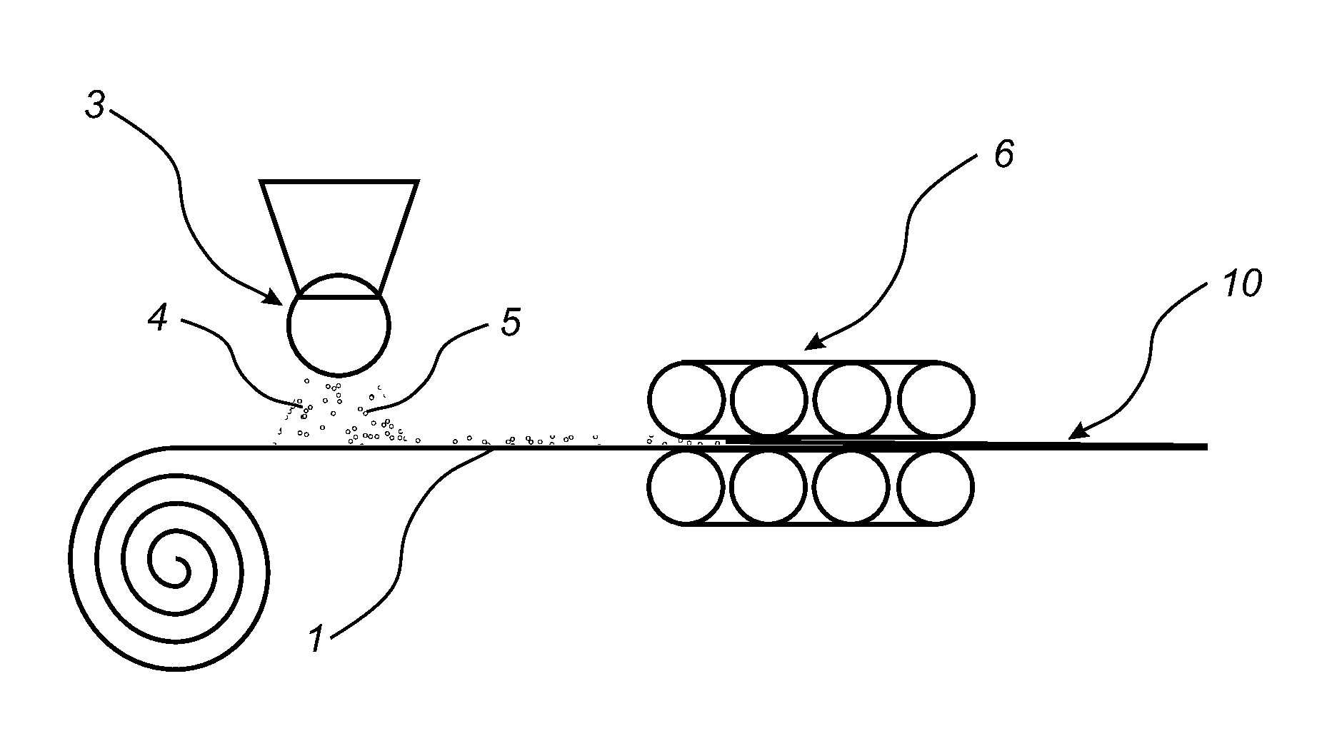
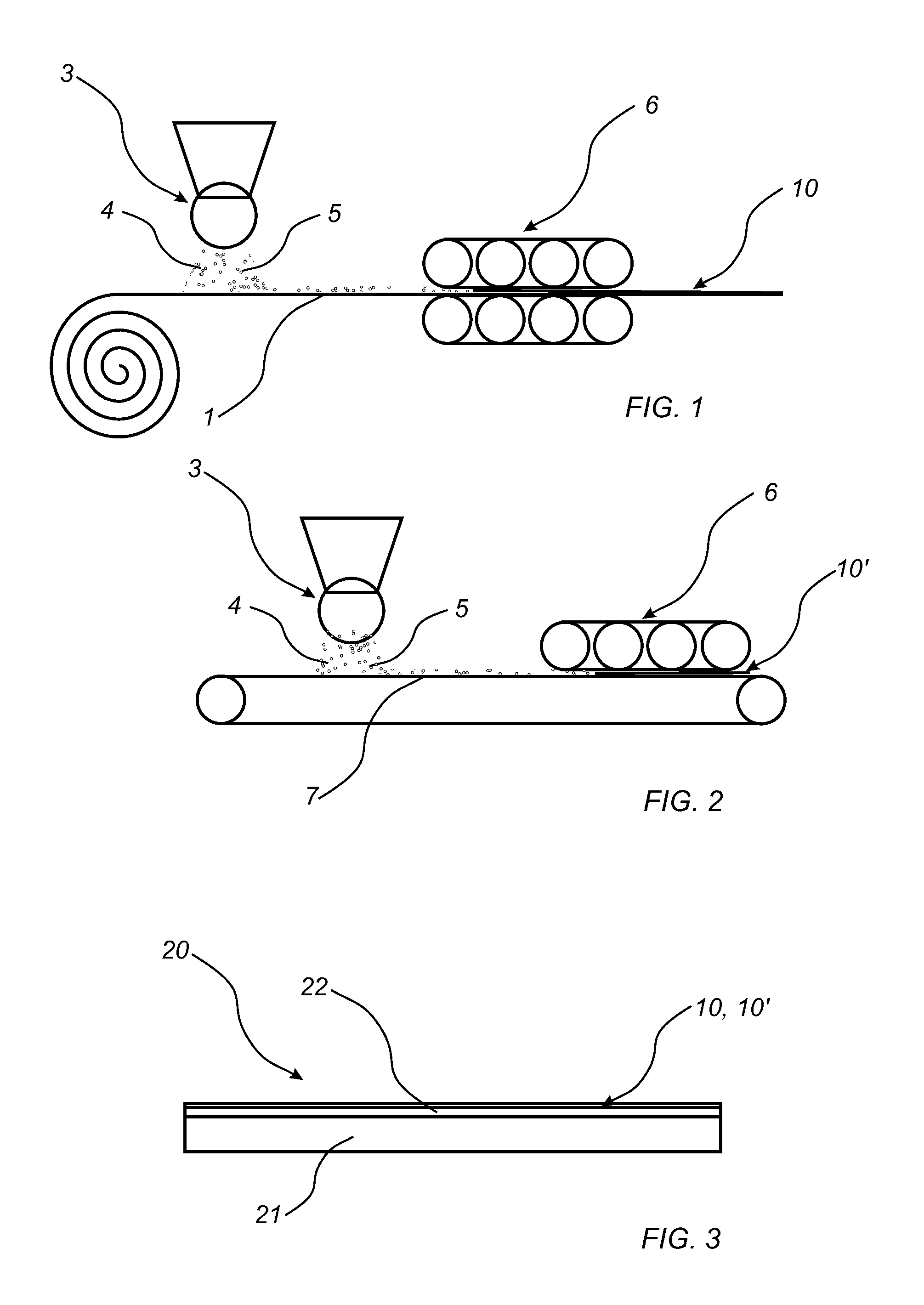
The second thermoplastic material may be in powder form when applied on the first foil.
The second thermoplastic material may be in powder form when adhered to the first foil, such as, for example, when being pressed to the first foil.
The first foil, the second thermoplastic material and the wear resistant particles may be adhered to each other by pressing the first foil, the wear resistant particles and the second thermoplastic material together.
The wear resistant foil is preferably transparent, or at least substantially transparent, for example, having a light transmittance index exceeding 80%, preferably exceeding 90%.
Thereby, any decorative layer or decorative print is visible through the wear resistant foil. Preferably, the wear resistant foil does not influence of the impression of any decorative layer or decorative print arranged beneath the wear resistant foil. The wear resistant foil is preferably non-pigmented.
The wear resistant particles may be enclosed by the first foil and the second thermoplastic material after being adhered to each other. The wear resistant particles may be encapsulated by the second foil. Preferably, the wear resistant particles do not protrude from a surface of a layer formed by the second thermoplastic material after being adhered to the first layer. If the wear resistant particles protrude beyond the surface of the layer formed by the second thermoplastic material, the wear resistance foil will cause wear on items placed on the wear resistance foil. For example, when the wear resistant foil is used a top surface of a flooring, protruding wear resistant particles will cause wear on socks, shoes, etc. Further, protruding wear resistant particles would cause a rough and/or harsh surface of the wear resistant foil, as provided by a slip resistant surface. The aim of the wear resistant particles enclosed by the thermoplastic material is to provide wear resistance when the second foil is worn, not to provide slip resistance.
The wear resistant particles and the second thermoplastic material may be applied as a mix. As an alternative or complement, the wear resistant particles and the second thermoplastic material may be applied separately.
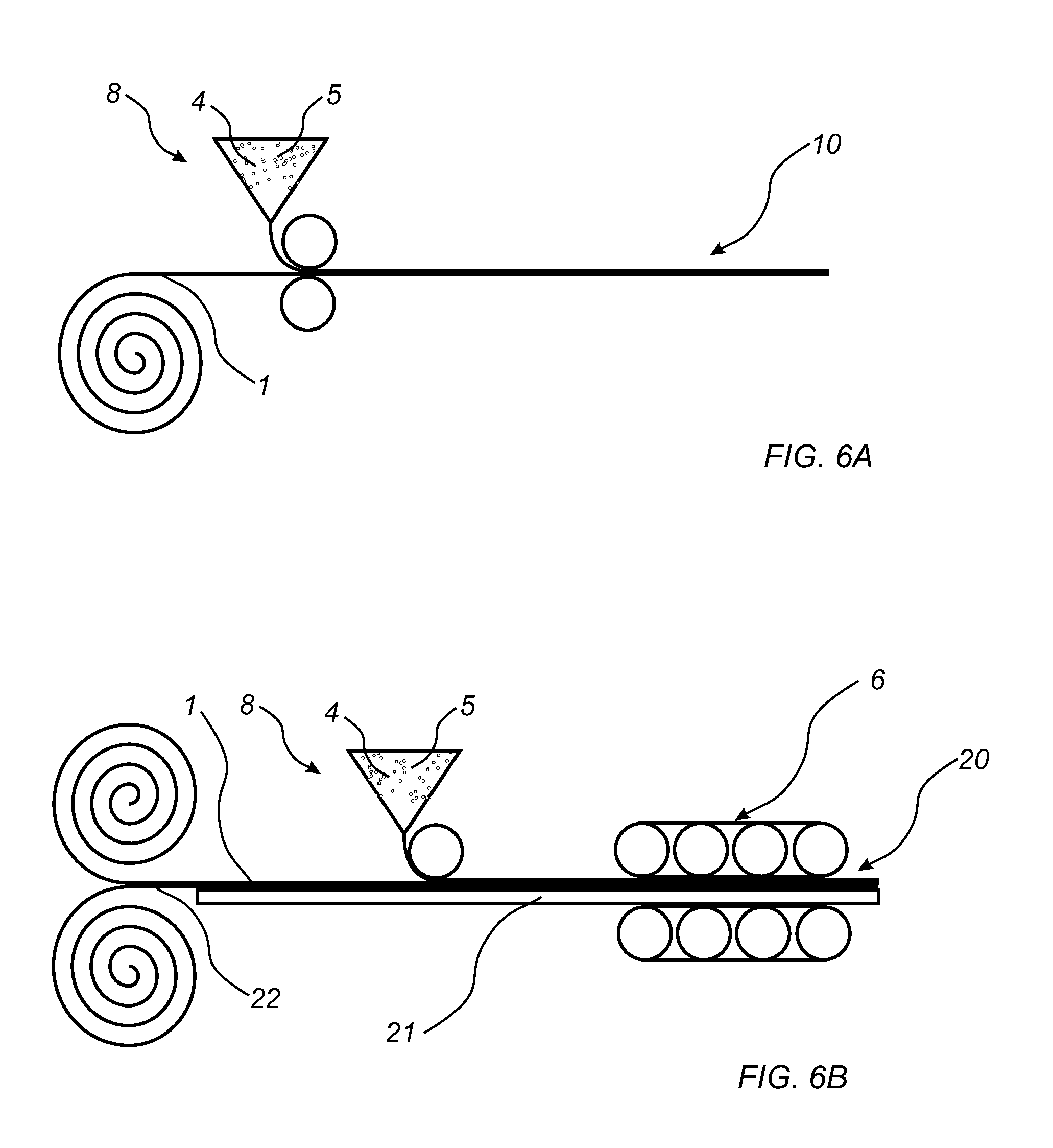
The second thermoplastic material may be applied in molten form. The second thermoplastic material may be applied in an extrusion process such as extrusion lamination or extrusion coating on the first foil.
The first thermoplastic material may be or comprise polyvinyl chloride (PVC), polyester (PE), polypropylene (PP), polyethylene (PE), polystyrene (PS), polyurethane (PU), polyethylene terephthalate (PET), polyacrylate, methacrylate, polycarbonate, polyvinyl butyral, polybutylene terephthalate, or a combination thereof.
The second thermoplastic material may be or comprise polyvinyl chloride (PVC) or polyurethane (PU). The second thermoplastic material may be or comprise polyvinyl chloride (PVC), polyester (PE), polypropylene (PP), polyethylene (PE), polystyrene (PS), polyurethane (PU), polyethylene terephthalate (PET), polyacrylate, methacrylate, polycarbonate, polyvinyl butyral, polybutylene terephthalate, or a combination thereof.
The first foil may substantially consist of the thermoplastic material, preferably polyvinyl chloride, and optionally additives.
Additives may be plasticizers, stabilizers, lubricants, degassing agents, coupling agents, compatibilizers, crosslinking agents, etc.
The first foil may be a decorative foil. The first foil may be printed, for example by digital printing, direct printing, rotogravure printing, etc.
The second thermoplastic material may be or comprise polyvinyl chloride (PVC) or polyurethane (PU).
By arranging the second thermoplastic material being or comprising polyurethane, no additional polyurethane containing coating has to be provided on top of the wear resistant foil. Thereby, the layered structure of a LVT product may be simplified. Furthermore, compared to for example a conventional wear layer substantially consisting of PVC, a wear resistant foil comprising an upper portion of polyurethane (PU) obtains improved chemical resistance. Its scratch resistance and micro-scratch resistance are also improved. An upper layer of polyurethane (PU) also provides improved resistance against black heel mark. An additional advantage is that curable polyurethane, such as UV curable polyurethane, shrinks when curing. By pressing a thermoplastic polyurethane (PU) material, no, or at least reduced, such shrinking occurs.
In one embodiment, the first thermoplastic material may be or comprises polyvinyl chloride (PVC) and the second thermoplastic material comprises polyurethane (PU). Thereby, a wear resistant foil having the properties of both polyvinyl chloride (PVC) and polyurethane (PU) is provided.
The wear resistant particles comprise aluminium oxide. The wear resistant may comprise carborundum, quartz, silica, glass, glass beads, glass spheres, silicon carbide, diamond particles, hard plastics, reinforced polymers and organics.
The wear resistant particles may have an average particle size of less than 45 .mu.m.
The wear resistant particles may have a refractive index similar to the refractive index of the second thermoplastic material. The wear resistant particles may have a refractive index of 1.4-1.7. In one embodiment, the wear resistant particle may have a refractive index of 1.4-1.9, preferably 1.5-1.8, for example, 1.7-1.8. The refractive index of the wear resistant particles may not differ from the refractive index of the second thermoplastic material more than .+-.20%.
A layer formed by the second thermoplastic material and the wear resistant particles may have a thickness being less than 75 .mu.m, for example, such as about 50 .mu.m, after being adhered to the first foil, for example, by pressing.
The wear resistant particles may have an average particle size being less than the thickness of the layer formed by the second thermoplastic material and the wear resistant particles. The wear resistant particles may have an average particle size being larger than the thickness of the layer formed by the second thermoplastic material and the wear resistant particles. However, during pressing, the wear resistant particles are pressed into the first foil such that the wear resistant particles do not protrude beyond an upper surface of the layer formed by the second thermoplastic material and the wear resistant particles after pressing, although the wear resistant particles having an average particle size exceeding the thickness of the layer formed by the second thermoplastic material and the wear resistant particles.
The ratio between the size of the wear resistant particles and the thickness of the layer formed by the second thermoplastic material and the wear resistant particles may be less than 1.5:1.
The thickness of the layer formed by the second thermoplastic material and the wear resistant particles may be less than the thickness of the first foil.
The method may further comprise applying scratch resistant particles on the first foil, or together with the second thermoplastic material. The scratch resistant particles may be or comprise nano-sized silica particles, preferably fused silica particles. The scratch resistant particles may be or comprise aluminium oxide.
According to a second aspect, a method of forming a building panel is provided. The method comprises applying a wear resistant foil produced according to the first aspect on a core, and applying pressure to the wear resistant foil and the core for forming a building panel.
The core may be provided with a decorative layer. The core may be provided with a print on a surface of the core. The wear resistant foil may be arranged on the decorative layer, or on the print. Alternatively, the first foil of the wear resistant foil may be a decorative layer.
The core may comprise a third thermoplastic material.
The first, second and third thermoplastic material may be thermoplastic materials of different types, or may be the same type of thermoplastic material. The first, second and third thermoplastic material may be or comprise any one of the follow group: polyvinyl chloride (PVC), polyester, polypropylene (PP), polyethylene (PE), polystyrene (PS), polyurethane (PU), polyethylene terephthalate (PET), polyacrylate, methacrylate, polycarbonate, polyvinyl butyral, polybutylene terephthalate, or a combination thereof. The core may be a thermoplastic core, a WPC (Wood Plastic Composite), etc. The core may be provided with several layers. The core may be foamed.
The core may be a wood-based board or a mineral board. The core may in embodiments be HDF, MDF, particleboard, OSB, Wood Plastic Composite (WPC).
The decorative layer may be a thermoplastic foil. The decorative layer may comprise any of the thermoplastic material listed above.
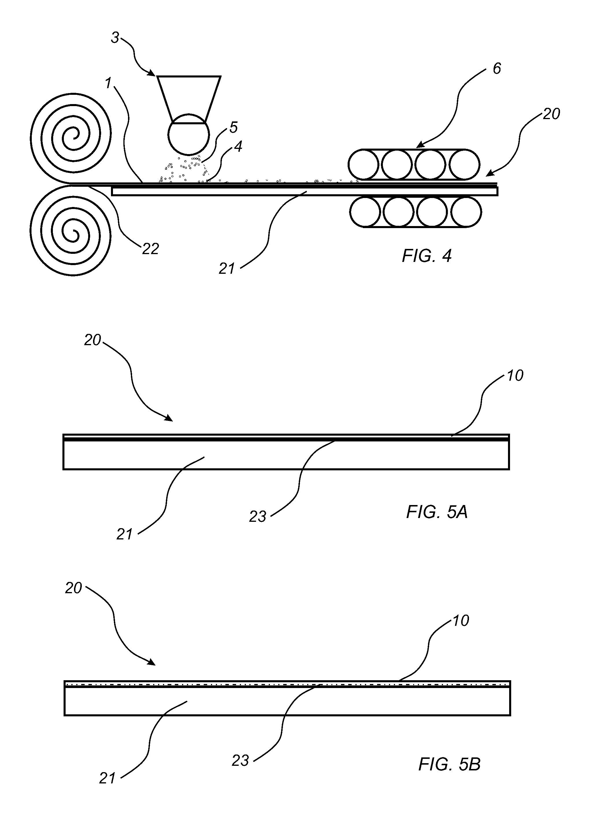
According to a third aspect, a method to produce a building panel is provided. The method includes providing a core, applying a first foil comprising a first thermoplastic material on the core, applying wear resistant particles and a second thermoplastic material on the first foil, and adhering the core to the first foil to the second thermoplastic material and the wear resistant particles to each other to form a building panel.
The first and the second thermoplastic material may be thermoplastic materials of different type, or may be thermoplastic material of the same type.
In one embodiment, the wear resistant foil is produced in connection with forming the building panel. The wear resistant foil may be laminated together when laminating any other layer, for example a decorative layer, a balancing layer, etc., to the core.
An advantage of at least embodiments of the present disclosure is that a wear resistant foil having improved wear resistance is provided. By including wear resistant particles in the wear resistant foil, the wear resistant particles provide additional wear resistance to the thermoplastic materials of the first and the second foil. The wear resistance of the foil is improved compared to a conventional wear layer of LVT products.
Furthermore, conventional coatings, for example a UV curable PU coating conventionally applied on the wear layer, may be replaced by using the wear resistant foil according to the disclosure instead. A conventional coating step may be replaced by arranging a single foil. Thereby, the production process is simplified and the number of steps in the production process is reduced by arranging a wear resistant foil having improved wear resistant properties instead of several layers or coatings.
By using different thermoplastic material in the first foil and in the second thermoplastic material applied on the first foil, it is possible to benefit from different thermoplastic material having different properties. The desired properties of the thermoplastic material of the first foil may differ from the desired properties of the second thermoplastic material applied on the first foil. For the layer formed by the second thermoplastic material and the wear resistant particles arranged on the first foil, properties such as stain resistance and scratch resistance are important, and the choice of the thermoplastic material can be chosen to match these criteria. Usually, suitable thermoplastic material for forming the layer applied on the first foil may be more expensive compared to thermoplastic material used as, for example, in printed film or as core material. By only using such thermoplastic material in the layer arranged on the first foil, the cost of the wear resistant foil can be controlled. Further, the layer formed by the second thermoplastic material can have a layer thickness being less than a layer thickness of the first foil. By choosing different thermoplastic materials for the first foil and the overlying layer, the thermoplastic materials can be used in an efficient and cost effective manner. By adjusting the layer thicknesses, the materials can be used in an even more efficient manner.
The object of the wear resistant particles is to provide wear resistance of the foil when being worn, not to provide slip resistance.
The second thermoplastic material may be in powder form when applied on the first foil.
The wear second thermoplastic material may be in powder form when adhered to the first foil, such as, for example, when pressed to the first foil.
The first foil, the second thermoplastic material and the wear resistant particles may be adhered to each other by pressing the first foil, the wear resistant particles and the second thermoplastic material together.
The first foil together with the wear resistant particles and the second thermoplastic material form a wear resistant foil, preferably being transparent, or at least substantially transparent, for example, having a light transmittance index exceeding 80%, preferably exceeding 90%. Thereby, any decorative layer or decorative print is visible through the wear resistant foil. Preferably, the wear resistant foil does not influence of the impression of any decorative layer or decorative print arranged beneath the wear resistant foil. The wear resistant foil is preferably non-pigmented.
The wear resistant particles may be enclosed by the first foil and the second thermoplastic material after being adhered to each other.
Preferably, the wear resistant particles do not protrude from a surface of a layer formed by the second thermoplastic material opposite the first foil after pressing. If the wear resistant particles protrude beyond the surface of the second thermoplastic material, the wear resistance foil will cause wear on items placed on the wear resistance foil. For example, when the wear resistant foil is used a top surface of a flooring, protruding wear resistant particles will cause wear on socks, shoes, etc. Further, protruding wear resistant particles would cause a rough and/or harsh surface of the wear resistant foil, as provided by a slip resistant surface. The aim of the wear resistant particles enclosed by the thermoplastic material is to provide wear resistance when the second thermoplastic material is worn, not to provide slip resistance.
The wear resistant particles and the second thermoplastic material may be applied as a mix. As an alternative or complement, the wear resistant particles and the second thermoplastic material may be applied separately.
The second thermoplastic material may be applied in molten form. The second thermoplastic material may be applied in an extrusion process such as extrusion lamination or extrusion coating on the first foil.
The first thermoplastic material may be or comprise polyvinyl chloride (PVC), polyester (PE), polypropylene (PP), polyethylene (PE), polystyrene (PS), polyurethane (PU), polyethylene terephthalate (PET), polyacrylate, methacrylate, polycarbonate, polyvinyl butyral, polybutylene terephthalate, or a combination thereof.
The second thermoplastic material may be or comprise polyvinyl chloride (PVC) or polyurethane (PU). The second thermoplastic material may be or comprise polyvinyl chloride (PVC), polyester (PE), polypropylene (PP), polyethylene (PE), polystyrene (PS), polyurethane (PU), polyethylene terephthalate (PET), polyacrylate, methacrylate, polycarbonate, polyvinyl butyral, polybutylene terephthalate, or a combination thereof.
In one embodiment, the first thermoplastic material comprises polyvinyl chloride (PVC) and the second thermoplastic material comprises polyurethane (PU).
The wear resistant particles may preferably comprise aluminium oxide. The wear resistant particles may comprise aluminium oxide such as corundum, carborundum, quartz, silica, glass, glass beads, glass spheres, silicon carbide, diamond particles, hard plastics, reinforced polymers and organics, or combinations thereof.
The wear resistant particles may have an average particle size of less than 45 .mu.m.
The wear resistant particles may have a refractive index similar to the refractive index of the second thermoplastic material. The wear resistant particles may have a refractive index of 1.4-1.7. In one embodiment, the wear resistant particle may have a refractive index of 1.4-1.9, preferably 1.5-1.8, for example, 1.7-1.8. The refractive index of the wear resistant particles may not differ from the refractive index of the second thermoplastic material more than .+-.20%.
A layer formed by the second thermoplastic material and the wear resistant particles may have a thickness being less than 75 .mu.m, for example, such as about 50 .mu.m, after being adhered to each other.
The wear resistant particles may have an average particle size being less than the thickness of the layer formed by the second thermoplastic material and the wear resistant particles. The wear resistant particles may have an average particle size being larger than the thickness of the layer formed by the second thermoplastic material and the wear resistant particles. However, during pressing, the wear resistant particles are pressed into the first foil such that the wear resistant particles do not protrude beyond an upper surface of the layer formed by the second thermoplastic material and the wear resistant particles after pressing, although the wear resistant particles having an average particle size exceeding the thickness of the layer formed by the second thermoplastic material and the wear resistant particles.
The ratio between the size of the wear resistant particles and the thickness of the layer formed by the second thermoplastic material and the wear resistant particles may be less than 1.5:1.
The thickness of the layer formed by the second thermoplastic material and the wear resistant particles may be less than the thickness of the first foil.
The method may further comprise applying scratch resistant particles on the first foil. Alternatively, or as a complement, the scratch particles may be applied together with the second thermoplastic material. The scratch resistant particles may be or comprise nano-sized silica particles, preferably fused silica particles. The scratch resistant particles may be or comprise aluminium oxide.
The core may comprise a third thermoplastic material.
The first, second and third thermoplastic material may be thermoplastic materials of different types, or may be the same type of thermoplastic material.
The third thermoplastic material may be or comprise polyvinyl chloride (PVC), polyester, polypropylene (PP), polyethylene (PE), polystyrene (PS), polyurethane (PU), polyethylene terephthalate (PET), polyacrylate, methacrylate, polycarbonate, polyvinyl butyral, polybutylene terephthalate, or a combination thereof. The core may be a thermoplastic core, a WPC (Wood Plastic Composite), etc. The core may be provided with several layers. The core may be foamed.
The core may be a wood-based board or a mineral board. The core may in embodiments be HDF, MDF, particleboard, OSB, Wood Plastic Composite (WPC).
A decorative layer may be arranged on the core. In one embodiment, the method may comprise applying a decorative layer prior to applying the first foil. The decorative layer may be a thermoplastic layer. The decorative layer may be a wood powder layer comprising a thermosetting binder and lignocellulosic or cellulosic particles. The decorative layer may be a thermoplastic layer applied as a powder, preferably comprising a print printed into the thermoplastic material in powder form. The decorative layer may be a wood veneer layer, a cork layer or a decorative paper.
In one embodiment, the first foil is arranged directly on the core. The core may be provided with a print, and the first foil is arranged on the print. Alternatively, or as a complement, the first foil may be a decorative foil. The first foil may be printed, for example by digital printing, direct printing, rotogravure, etc. Preferably, the print is provided on a surface of the first foil facing the core.
The method may further comprise applying a coating on the wear resistant foil. The coating may comprise acrylate or methacrylate monomer or acrylate or methacrylate oligomer. The coating may be radiation curing, such as UV curing or electron beam curing.
According a fourth aspect, a method to produce a wear resistant foil is provided. The method comprises providing a carrier, applying wear resistant particles and a second thermoplastic material on the carrier, and adhering the wear resistant particles and the second thermoplastic material to each other to form a wear resistant foil.
Embodiments of the fourth aspect all the advantages of the first aspect, which previously has been discussed, whereby the previous discussion is applicable also for the building panel.
The second thermoplastic material may be in powder form when applied on the carrier.
The wear second thermoplastic material may be in powder form when adhered to the carrier, such as, for example, when pressed to the carrier.
The first foil, the second thermoplastic material and the wear resistant particles may be adhered to each other by pressing the first foil, the wear resistant particles and the second thermoplastic material together.
The wear resistant foil is preferably transparent, or at least substantially transparent, for example, having a light transmittance index exceeding 80%, preferably exceeding 90%. Thereby, any decorative layer or decorative print is visible through the wear resistant foil. Preferably, the wear resistant foil does not influence of the impression of any decorative layer or decorative print arranged beneath the wear resistant foil. The wear resistant foil is preferably non-pigmented.
The wear resistant particles may be enclosed by the first foil and the second thermoplastic material after being adhered to each other.
Preferably, the wear resistant particles do not protrude from a surface of a layer formed by the second thermoplastic material after being adhered to the first foil. If the wear resistant particles protrude beyond the surface of the layer formed by the second thermoplastic material, the wear resistance foil will cause wear on items placed on the wear resistance foil. For example, when the wear resistant foil is used a top surface of a flooring, protruding wear resistant particles will cause wear on socks, shoes, etc. Further, protruding wear resistant particles would cause a rough and/or harsh surface of the wear resistant foil, as provided by a slip resistant surface. The aim of the wear resistant particles enclosed by the second thermoplastic material is to provide wear resistance when the second foil is worn, not to provide slip resistance.
The wear resistant particles and the second thermoplastic material may be applied as a mix. As an alternative or complement, the wear resistant particles and the second thermoplastic material may be applied separately.
The second thermoplastic material may be applied in molten form. The second thermoplastic material may be applied in an extrusion process such as extrusion lamination or extrusion coating on the carrier.
In one embodiment, the carrier may be a first foil comprising a first thermoplastic material as discussed above in respect of the third aspect.
The carrier may be a substrate.
In one embodiment, the carrier may be a temporary carrier such as a release foil or conveyor means.
In one embodiment, the carrier may be a core. The core may be a thermoplastic core, a Wood Plastic Composite (WPC), a wood-based board or a mineral board. The step of adhering may comprise adhering the carrier to the second thermoplastic material and the wear resistant particles.
The second thermoplastic material may be or comprise polyvinyl chloride (PVC) or polyurethane (PU).
The method may further comprise releasing the wear resistant foil from the carrier.
The wear resistant particles may comprise aluminium oxide. The wear resistant may comprise carborundum, quartz, silica, glass, glass beads, glass spheres, silicon carbide, diamond particles, hard plastics, reinforced polymers and organics.
The wear resistant particles may have an average particle size of less than 45 .mu.m.
The wear resistant particles may have a refractive index similar to the refractive index of the second thermoplastic material. The wear resistant particles may have a refractive index of 1.4-1.7. In one embodiment, the wear resistant particle may have a refractive index of 1.4-1.9, preferably 1.5-1.8, for example, 1.7-1.8. The refractive index of the wear resistant particles may not differ from the refractive index of the second thermoplastic material more than .+-.20%.
A layer formed by the second thermoplastic material and the wear resistant particles may have a thickness being less than 75 .mu.m, for example, such as about 50 .mu.m, after being adhered to each other.
The wear resistant particles may have an average particle size being less than the thickness of the layer formed by the second thermoplastic material and the wear resistant particles. The wear resistant particles may have an average particle size being larger than the thickness of the layer formed by the second thermoplastic material and the wear resistant particles. However, during pressing, the wear resistant particles are pressed into the carrier such that the wear resistant particles do not protrude beyond an upper surface of the layer formed by the second thermoplastic material and the wear resistant particles after pressing, although the wear resistant particles having an average particle size exceeding the thickness of the layer formed by the second thermoplastic material and the wear resistant particles.
The ratio between the size of the wear resistant particles and the thickness of the layer formed by the second thermoplastic material and the wear resistant particles may be less than 1.5:1.
According a fifth aspect, a building panel is provided. The building panel comprises a core, a wear resistant foil arranged on a surface of the core, wherein the wear resistant foil comprises a second thermoplastic material and wear resistant particles substantially homogenously distributed in said second thermoplastic material.
Embodiments of the fifth aspect incorporate all the advantages of the first, which previously has been discussed, whereby the previous discussion is applicable also for the building panel.
The wear resistant foil is preferably transparent, or at least substantially transparent, for example, having a light transmittance index exceeding 80%, preferably exceeding 90%. Thereby, any decorative layer or decorative print is visible through the wear resistant foil. Preferably, the wear resistant foil does not influence of the impression of any decorative layer or decorative print arranged beneath the wear resistant foil. The wear resistant foil is preferably non-pigmented.
The wear resistant particles may be enclosed by the second thermoplastic material.
Preferably, the wear resistant particles do not protrude from a surface of a layer formed by the second thermoplastic material. If the wear resistant particles protrude beyond the surface of the second foil, the wear resistance foil will cause wear on items placed on the wear resistance foil. For example, when the wear resistant foil is used a top surface of a flooring, protruding wear resistant particles will cause wear on socks, shoes, etc. Further, protruding wear resistant particles would cause a rough and/or harsh surface of the wear resistant foil, as provided by a slip resistant surface. The aim of the wear resistant particles enclosed by the thermoplastic material is to provide wear resistance when the second foil is worn, not to provide slip resistance.
The wear resistant foil may further comprise a first foil comprising a first thermoplastic material.
The first thermoplastic material may be or comprise polyvinyl chloride (PVC). The first thermoplastic material may be or comprise polyvinyl chloride (PVC), polyester (PE), polypropylene (PP), polyethylene (PE), polystyrene (PS), polyurethane (PU), polyethylene terephthalate (PET), polyacrylate, methacrylate, polycarbonate, polyvinyl butyral, polybutylene terephthalate, or a combination thereof.
The second thermoplastic material may be or comprise polyvinyl chloride (PVC) or polyurethane (PU). The second thermoplastic material may be or comprise polyvinyl chloride (PVC), polyester (PE), polypropylene (PP), polyethylene (PE), polystyrene (PS), polyurethane (PU), polyethylene terephthalate (PET), polyacrylate, methacrylate, polycarbonate, polyvinyl butyral, polybutylene terephthalate, or a combination thereof.
The wear resistant particles may preferably comprise aluminium oxide. The wear resistant particles may comprise aluminium oxide, carborundum, quartz, silica, glass, glass beads, glass spheres, silicon carbide, diamond particles, hard plastics, reinforced polymers and organics, or a combination thereof.
The wear resistant particles may have an average particle size of less than 45 .mu.m.
The wear resistant particles may have a refractive index similar to the refractive index of the second thermoplastic material. The wear resistant particles may have a refractive index of 1.4-1.7. In one embodiment, the wear resistant particle may have a refractive index of 1.4-1.9, preferably 1.5-1.8, for example, 1.7-1.8. The refractive index of the wear resistant particles may not differ from the refractive index of the second thermoplastic material more than .+-.20%.
A layer formed by the second thermoplastic material and the wear resistant particles may have a thickness being less than 75 .mu.m, for example, such as about 50 .mu.m, after being adhered.
The wear resistant particles may have an average particle size being less than the thickness of the layer formed by the second thermoplastic material and the wear resistant particles. The wear resistant particles may have an average particle size being larger than the thickness of the layer formed by the second thermoplastic material and the wear resistant particles. However, during pressing, the wear resistant particles are pressed into the core or any intermediate layer such as a first foil such that the wear resistant particles do not protrude beyond an upper surface of the layer formed by the second thermoplastic material and the wear resistant particles after pressing, although the wear resistant particles having an average particle size exceeding the thickness of the layer formed by the second thermoplastic material and the wear resistant particles.
The ratio between the size of the wear resistant particles and the thickness of the layer formed by the second thermoplastic material and the wear resistant particles may be less than 1.5:1.
The thickness of the layer formed by the second thermoplastic material and the wear resistant particles may be less than the thickness of the first foil.
The building panel may further comprise a decorative layer arranged on the core, wherein the wear resistant foil is arranged on the decorative layer.
The core may comprise a third thermoplastic material. The third thermoplastic material may be or comprise polyvinyl chloride (PVC), polyester, polypropylene (PP), polyethylene (PE), polystyrene (PS), polyurethane (PU), polyethylene terephthalate (PET), polyacrylate, methacrylate, polycarbonate, polyvinyl butyral, polybutylene terephthalate, or a combination thereof.
The core may be a thermoplastic core, a Wood Plastic Composite (WPC), a wood-based board or a mineral board.
BRIEF DESCRIPTION OF THE DRAWINGS
The present disclosure will by way of example be described in more detail with reference to the appended schematic drawings, which show embodiments of the present disclosure.
FIG. 1 shows a method to produce a wear resistant foil according a first embodiment.
FIG. 2 shows a method to produce a wear resistant foil according to a second embodiment.
FIG. 3 shows a building panel.
FIG. 4 shows a method to produce a building panel.
FIGS. 5A-B show embodiments of a building panel.
FIG. 6A shows a method to produce a wear resistant foil.
FIG. 6B shows a method to produce a building panel.
DETAILED DESCRIPTION
A method to produce a wear resistant foil 10 according to an embodiment will now be described with reference to FIG. 1. FIG. 1 shows a production line for producing a wear resistant foil 10.
The first foil 1 comprises a first thermoplastic material. The first thermoplastic material may be polyvinyl chloride (PVC), polyester, polypropylene (PP), polyethylene (PE), polystyrene (PS), polyurethane (PU), polyethylene terephthalate (PET), polyacrylate, methacrylate, polycarbonate, polyvinyl butyral, polybutylene terephthalate, or a combination thereof.
In FIG. 1, the first foil 1 is provided as a continuous web. In other embodiments, the first foil 1 may also be cut into sheets. The first foil 1 may also be formed by an extrusion process. The first foil 1 may also be formed of a powder layer comprising the first thermoplastic material in powder form.
Preferably, the first foil 1 is formed of the thermoplastic material. The first foil 1 may substantially consist of the thermoplastic material, and optionally additives. Additives may be plasticizers, stabilizers, lubricants, degassing agents, coupling agents, compatibilizers, crosslinking agents, etc.
In one embodiment, the first foil 1 is a PVC foil.
The first foil 1 may have a thickness of 0.1-1 mm.
In one embodiment, the first foil 1 is a decorative foil. The first foil 1 may be printed, for example by digital printing, direct printing, rotogravure, etc.
As shown in FIG. 1, an applying device 3 applies, preferably scatters, a second thermoplastic material 5 in powder form and wear resistant particles 4 on the first foil 1. In FIG. 1, the thermoplastic material 5 and the wear resistant particles 4 are applied as a mix. The thermoplastic material 5 and the wear resistant particles 4 may also be applied separately. Preferably, if applied separately, the wear resistant particles 4 are applied first, and the second thermoplastic material 5 is applied on the wear resistant particles 4.
The second thermoplastic material 5 may be the same as in the first foil 1, or being different from the thermoplastic material of the first foil 1. The second thermoplastic material 5 may be polyvinyl chloride (PVC), polyester, polypropylene (PP), polyethylene (PE), polystyrene (PS), polyurethane (PU), polyethylene terephthalate (PET), polyacrylate, methacrylate, polycarbonate, polyvinyl butyral, polybutylene terephthalate, or a combination thereof.
In the embodiment shown in FIG. 1, the second thermoplastic material 5 is applied as a powder. By powder is also meant powder that has formed granules of the thermoplastic material, dry blends of the thermoplastic material, or agglomerates of the thermoplastic material. The granules may comprise both the thermoplastic material 5 and the wear resistant particles 4. The agglomerates may comprise both the thermoplastic material 5 and the wear resistant particles 4.
The average particle size of the thermoplastic material 5 may be less than 500 .mu.m, preferably 50-250 .mu.m. The thermoplastic material 5 in a dry blend may have size of less than 500 .mu.m. Granules of the thermoplastic material 5 may have an average particle size of 200-4000 .mu.m, preferably less than 1000 .mu.m.
In the embodiment shown in FIG. 1, the wear resistant particles 4 and the second thermoplastic material 5 is applied as a mix.
In embodiments, the second thermoplastic material 5 may be applied in molten form, which is described in more detail with reference to FIG. 6A. The wear resistant particles 4 may be mixed with the second thermoplastic material 5 in molten form or applied separately. The second thermoplastic 5 in molten form may be applied in an extrusion process such as extrusion lamination and extrusion coating on the first foil 1.
The wear resistant particles 4 may be aluminium oxide particles such as corundum. Alternatively, or as a complement, the wear resistant particles 4 may be carborundum, quartz, silica, glass, glass beads, glass spheres, silicon carbide, diamond particles, hard plastics, reinforced polymers and organics.
The wear resistant particles 4 preferably have an average particle size within the range of 10-200 .mu.m, preferably within the range of 50-120 .mu.m such as 50-100 .mu.m. The wear resistant particles 4 may have an average particle size of less than 50 .mu.m, preferably less than 45 .mu.m. The wear resistant particles 4 may have a spherical shape or an irregular shape. The wear resistant particles 4 may be surface treated. The wear resistant particles 4 may be silane-treated particles.
The wear resistant particles 4 may have a refractive index similar to the refractive index of the second thermoplastic material 5. The wear resistant particles may have a refractive index of 1.4-1.7. In one embodiment, the wear resistant particle may have a refractive index of 1.4-1.9, preferably 1.5-1.8, for example, 1.7-1.8. The refractive index of the wear resistant particles may not differ from the refractive index of the second thermoplastic material more than .+-.20%.
The wear resistant particles may be applied in an amount of 20-100 g/m2, preferably in an amount of 40-60 g/m2.
The wear resistant particles may have an average particle size being less than the thickness of the layer formed by the wear resistant particles and the second thermoplastic material after pressing. However, the wear resistant particles may have an average particle size being larger than the thickness of the layer formed by the wear resistant particles and the second thermoplastic material 5 after pressing. During pressing, the wear resistant particles are pressed into the first foil such that the wear resistant particles do not protrude beyond an upper surface of the layer formed by the second thermoplastic material 5, although the wear resistant particles having an average particle size exceeding the thickness of the layer formed by the wear resistant particles and the second thermoplastic material after pressing.
The ratio between the size of the wear resistant particles and the thickness of the layer formed by the wear resistant particles and the second thermoplastic material after pressing may be less than 1.5:1.
Scratch resistant particles (not shown) may also be applied on the first foil 1, as a mix together with the thermoplastic material 5 and the wear resistant particles 4 or separately. By scratch resistant particles are meant particles improving the scratch or scratch resistant properties of the foil. The scratch resistant particles may be applied together with the wear resistant particles 4, for example as a mix, or may be applied separately. Preferably, the scratch particles are arranged on an upper part of the layer formed by the thermoplastic material 5 and the wear resistant particles 4. The scratch resistant particles may be may be or comprise nano-sized silica particles, preferably fused silica particles. The scratch resistant particles may be or comprise aluminium oxide.
The scratch resistant particles may be disc shaped particles, preferably having a width/thickness ratio being equal or exceeding 3:1, more preferably being equal or exceeding 5:1. Such disc-shaped particles orientate along the surface of the foil, thereby improving the scratch resistance of the foil. The scratch resistant particles may have an average particle size of 1-50 .mu.m, preferably 10-20 .mu.m.
Additives may also be applied on the first foil 1, or together with the second thermoplastic material. Additives may be plasticizers, stabilizers, lubricants, degassing agents, coupling agents, compatibilizers, crosslinking agents, etc.
In one embodiment, the first foil 1 is a PVC foil and the second thermoplastic material 5 is polyurethane (PU) in powder form. In one embodiment, the first foil 1 is a PVC foil and the second thermoplastic material 5 is PVC in powder form.
The first foil 1 and the second thermoplastic material 5 in powder form are thereafter adhered to each other, for example, being pressed together, to form a wear resistant foil 10 comprising the first foil 1, the second thermoplastic material 5 and the wear resistant particles 4.
The first foil 1 and the second thermoplastic material 5 in powder form may be pressed together in a calendering process. As shown in FIG. 1, the first foil 1 and the second thermoplastic material 5 in powder form are pressed together in continuous press 6. The first and second thermoplastic material may be adhered together by pressure alone, by heat and pressure, by pressure and adhesive, or by heat, pressure, and adhesive. Preferably, both pressure and heat is applied in order to adhere the first foil and the second thermoplastic material together. As alternative or complements to a calendering process, a continuous or static press may also be used. The pressing operation may for example be made as a hot-hot process, a hot-cold process, etc. The pressing may be made with an embossed press matrix or press roller, such that an embossed structure is formed in the wear resistant foil.
Depending on the thermoplastic materials and process used, the pressure applied may be 5-100 bar, applied for example during 5-500 seconds. The temperature may be 80-300.degree. C., such as 100-250.degree. C., such as 150-200.degree. C.
By the process described above with reference to FIG. 1, a wear resistant foil 10 is formed. The wear resistant foil 10 may be formed as a continuous foil, or be cut into sheets. The second thermoplastic material 5 and the wear resistant particles 4 form an upper part of the wear resistant foil 10. Preferably, the wear resistant particles 4 may be substantially homogenous distributed in the upper part of the wear resistant foil 10. The first foil 1 forms a lower part of the wear resistant foil 10. As seen in a cross-section of the wear resistant foil, the wear resistant particles 4 are heterogeneously distributed through the wear resistant foil 10. There is a higher concentration of the wear resistant particles 4 in the upper parts of the wear resistant foil 10 than in the lower parts of the wear resistant foil 10.
After adhering the layers, the wear resistant particles are enclosed by the first foil and the second thermoplastic material. Although the wear resistant particles and the second thermoplastic material may be applied as mix, during the pressing, the second thermoplastic material fuses and encloses the wear resistant particles. Preferably, the wear resistant particles do not protrude beyond the surface of the layer formed the second thermoplastic material facing away from the first foil. Thereby, a wear resistant foil having a smooth surface can be formed.
The wear resistant foil 10 is preferably transparent, or substantially transparent.
The second thermoplastic material 5 and the wear resistant particles 4 may be formed into a layer, which may have a thickness of 0.01-1 mm, preferably as measured in the final product, for example, after pressing or extruding. Preferably, the layer formed by the second thermoplastic material 5 and the wear resistant particles 4 has a thickness less than 0.5 mm, more preferably less than 75 .mu.m such as about 50 .mu.m, preferably as measured in the final product, for example, after pressing or extruding.
Different additives may be included to the first foil 1 compared to the second thermoplastic material 5 in powder form in order to obtain different properties in different layers of the wear resistant foil 10.
A wear resistant foil 10' may also be produced in accordance with the embodiment described with reference to FIG. 2. In the embodiment shown in FIG. 2, a second thermoplastic material 5 in powder form and wear resistant particles 4 are applied, preferably scattered, by an applying device 3 on a carrier 7. The carrier 7 may be a substrate. The carrier 7 may for example be a release foil or Teflon.RTM. treated press plate. It is also contemplated that the carrier 7 may be a core 21, for example, provided with a print. The core 21 may a thermoplastic core, a WPC (Wood Plastic Composite), a wood-based board such as HDF or MDF, a mineral board, etc. It is also contemplated that a first thermoplastic material in powder form may be applied on the carrier.
The second thermoplastic material 5 may be polyvinyl chloride (PVC), polyester, polypropylene (PP), polyethylene (PE), polystyrene (PS), polyurethane (PU), polyethylene terephthalate (PET), polyacrylate, methacrylate, polycarbonate, polyvinyl butyral, polybutylene terephthalate, or a combination thereof.
By powder is also meant powder that has formed granules of the thermoplastic material 5, dry blends of the thermoplastic material 5, or agglomerates of the thermoplastic material 5. The granules may comprise both the thermoplastic material 5 and the wear resistant particles 4. The agglomerates may comprise both the thermoplastic material 5 and the wear resistant particles 4.
The average particle size of the thermoplastic material 5 may be less than 500 .mu.m, preferably 50-250 .mu.m. The thermoplastic material 5 in a dry blend may have size of less than 500 .mu.m. Granules of the thermoplastic material 5 may have an average particle size of 200-4000 .mu.m, preferably less than 1000 .mu.m.
A layer of the second thermoplastic material 5 is applied on the carrier 7. Preferably, the second thermoplastic material 5 and the wear resistant particles 4 are applied as a mix. The second thermoplastic material 5 and the wear resistant particles 4 may also be applied separately. Preferably, if applied separately, the wear resistant particles 4 are applied first, and the second thermoplastic material 5 is applied on the wear resistant particles 4.
In the embodiment shown in FIG. 2, the second thermoplastic material 5 is applied in powder form. In embodiments, the second thermoplastic material 5 may be applied in molten form, which is described in more detail with reference to FIG. 6A. The wear resistant particles 4 may be mixed with the second thermoplastic material 5 in molten form or applied separately. The second thermoplastic 5 in molten form may be applied in an extrusion process such as extrusion lamination and extrusion coating on the carrier 7.
More than one type of thermoplastic material 5 may be applied on the carrier 7. Thermoplastic materials having different properties may be applied. As an example, a PVC powder may be applied, and a PU powder may be applied on the PVC powder for forming a wear resistant foil 10' having different properties. The wear resistant particles 4 may be applied in between the PVC powder and the PU powder. Different types of additives may also be added to the different thermoplastic materials in order to form a wear resistant foil 10' having different properties in different layers.
The wear resistant particles 4 may be aluminium oxide particles such as corundum. Alternatively, or as a complement, the wear resistant particles 4 may be carborundum, quartz, silica, glass, glass beads, glass spheres, silicon carbide, diamond particles, hard plastics, reinforced polymers and organics, or a combination thereof.
The wear resistant particles 4 preferably have an average particle size within the range of 10-200 .mu.m, preferably within the range of 50-120 .mu.m, such as 50-100 .mu.m. The wear resistant particles 4 preferably have an average particle size of less than 50 .mu.m, preferably less than 45 .mu.m. The wear resistant particles 4 may have a spherical shape or an irregular shape. The wear resistant particles 4 may be surface treated. The wear resistant particles 4 may be silane-treated particles.
The wear resistant particles 4 may have a refractive index similar to the refractive index of the second thermoplastic material 5. The wear resistant particles may have a refractive index of 1.4-1.7. In one embodiment, the wear resistant particle may have a refractive index of 1.4-1.9, preferably 1.5-1.8, for example, 1.7-1.8. The refractive index of the wear resistant particles may not differ from the refractive index of the second thermoplastic material more than .+-.20%.
The wear resistant particles may be applied in an amount of 20-100 g/m2, preferably in an amount of 40-60 g/m2.
The wear resistant particles may have an average particle size being less than the thickness of the layer formed by the wear resistant particles and the second thermoplastic material after pressing. However, the wear resistant particles may have an average particle size being larger than the thickness of the layer formed by the wear resistant particles and the second thermoplastic material after pressing. During pressing, the wear resistant particles are pressed into the carrier such that the wear resistant particles do not protrude beyond an upper surface of the layer, although the wear resistant particles have an average particle size exceeding the thickness of the layer formed by the wear resistant particles and the second thermoplastic material after pressing.
The ratio between the size of the wear resistant particles and the thickness of the layer formed by the wear resistant particles and the second thermoplastic material after pressing may be less than 1.5:1.
Scratch resistant particles (not shown) may also be applied on the carrier 7, or as a mix together with the thermoplastic material 5 and the wear resistant particles 4 or separately. By scratch resistant particles are meant particles improving the scratch or scratch resistant properties of the foil. The scratch resistant particles may be applied together with the wear resistant particles 4, for example as a mix, or may be applied separately. Preferably, the scratch particles are arranged on an upper part of the layer formed by the thermoplastic material 5 and the wear resistant particles 4. The scratch resistant particles may be may be or comprise nano-sized silica particles, preferably fused silica particles. The scratch resistant particles may be or comprise aluminium oxide.
The scratch resistant particles may be disc shaped particles, preferably having a width/thickness ratio being equal or exceeding 3:1, more preferably being equal or exceeding 5:1. Such disc-shaped particles orientate along the surface of the foil, thereby improving the scratch resistance of the foil. The scratch resistant particles may have an average particle size of 1-50 .mu.m, preferably 10-20 .mu.m.
Additives may also be applied on the carrier 7. Additives may be plasticizers, stabilizers, lubricants, degassing agents, coupling agents, compatibilizers, crosslinking agents, etc.
The additives may also be applied together with the second thermoplastic material 5.
The second thermoplastic material 5 in powder form and the wear resistant particles 4 are thereafter adhered to each other such as fused together, preferably pressed together to form a wear resistant foil 10'.
The second thermoplastic material 5 in powder form and the wear resistant particles 4 may be pressed together in a calendering process. As shown in FIG. 2, the second thermoplastic material 5 and the wear resistant particles 4 are pressed together in a continuous press 6. Preferably, both pressure and heat is applied in order to form a wear resistant foil 10' of the second thermoplastic material 5 and the wear resistant particles 4. As alternative or complements to a calendaring process, a continuous or static press may also be used. The pressing may for example be made as a hot-hot process, a hot-cold process, etc. The pressing may be made with an embossed press matrix or press roller, such that an embossed structure is formed in the wear resistant foil 10'. As described above, the second thermoplastic material 5 may also be extruded on the carrier 7, such as extrusion coated or extrusion laminated to the carrier.
Depending on the thermoplastic materials and process used, the pressure applied may be 5-100 bar, applied for example during 5-500 seconds. The temperature may be 80-300.degree. C., such as 100-250.degree. C., such as 150-200.degree. C.
By the process described above with reference to FIG. 2, a wear resistant foil 10' is formed, comprising the second thermoplastic material and the wear resistant particles. The wear resistant foil 10' is preferably transparent, or substantially transparent.
The wear resistant foil may have a thickness of 0.01-1 mm, preferably as measured in the final product, for example, after pressing or extruding. Preferably, the wear resistant foil has a thickness less than 0.5 mm, more preferably less than 0.1 mm, preferably as measured in the final product, for example, after pressing or extruding.
After adhering the layers, the wear resistant particles are enclosed by the first foil and the second thermoplastic material. Although the wear resistant particles and the second thermoplastic material may be applied as mix, during the pressing, the second thermoplastic material fuses and encloses the wear resistant particles. Preferably, the wear resistant particles do not protrude beyond the surface of the layer formed the second thermoplastic material facing away from the first foil. Thereby, a wear resistant foil having a smooth surface can be formed.
The wear resistant foil 10, 10' produced accordance with the embodiments described when referring to FIG. 1 and FIG. 2, may in a subsequent step be adhered to a core 21 to form a building panel 20, as shown in FIG. 3. The building panel 20 may be a floor panel, a wall panel, a ceiling panel, a furniture component, etc.
The core 21 may comprise a third thermoplastic material. The third thermoplastic material may be the same as the first and/or second material, or be different from the first and/or the second material.
The third thermoplastic material may comprise polyvinyl chloride (PVC), polyester, polypropylene (PP), polyethylene (PE), polystyrene (PS), polyurethane (PU), polyethylene terephthalate (PET), polyacrylate, methacrylate, polycarbonate, polyvinyl butyral, polybutylene terephthalate, or a combination thereof. The core may be formed of several layers. The core may be foamed.
In one embodiment, the core 21 comprises the third thermoplastic material and fillers. The fillers may comprise calcium carbonate, such as chalk and/or limestone, or sand.
In one embodiment, the core 21 is a Wood Plastic Composite (WPC), comprising the third thermoplastic material and wood particles as fillers.
The core 21 may be provided with a decorative layer 22 arranged on a top surface of the core 21, as shown in FIG. 3. The wear resistant foil 10, 10' is then arranged on the decorative layer 22. The decorative layer 22 may be a decorative foil comprising a thermoplastic material. The thermoplastic material of the decorative layer may be or comprise polyvinyl chloride (PVC), polyester, polypropylene (PP), polyethylene (PE), polystyrene (PS), polyurethane (PU), polyethylene terephthalate (PET), polyacrylate, methacrylate, polycarbonate, polyvinyl butyral, polybutylene terephthalate, or a combination thereof. The decorative layer 22 is preferably printed, for example by direct printing, rotogravure, or digital printing.
The core 21 may also be provided with a balancing layer (not shown) arranged on a lower surface of the core 21, opposite the decorative layer 22. Any intermediate layer may also be arranged between the core 21 and the decorative layer 22.
The wear resistant foil 10, 10' produced according to the method described above with reference to FIG. 1 or FIG. 2, is arranged on the decorative layer. The core 21, the decorative layer 22, and the wear resistant foil 10, 10' are pressed together to form a building panel 20. Heat may also be applied when applying pressure. The core, the decorative layer and the wear resistant foil may be pressed together in a continuous or static press, or in a calendering operation. As alternatively, the wear resistant foil 10, 10', optionally comprising the decorative layer 22, may be adhered to the core 21 by an adhesive, such as hot melt.
The wear resistant foil 10, 10' is preferably transparent, or substantially transparent, for example, having a light transmittance index exceeding 80%, preferably exceeding 90%.
A coating (not shown) may be applied on the wear resistant foil 10, 10'. The coating may comprise acrylate or methacrylate monomer or acrylate or methacrylate oligomer. The coating may be radiation curing, such as UV curing or electron beam curing.
As an alternative to a separate decorative layer 22, a print may be printed directly on the top surface of core 21. The wear resistant foil 10, 10' is thereby arranged directly on the core 21.
In one embodiment, when the wear resistant foil 10 is produced according to the embodiment described with reference to FIG. 1, the first foil 1 forms a decorative layer. A separate decorative layer 22 may then be excluded. The first foil 1 may be printed, for example by digital printing, direct printing, rotogravure, etc. Preferably, the print is provided on side of the first foil 1 adapted to face the core 21. The wear resistant foil 10 is in this embodiment arranged directly on the core 21 of the above described type.
An embodiment of the building panel 20 comprises a core 21 comprising PVC, a decorative foil 22 comprising PVC, a wear resistant foil 10 comprising PVC in the first foil 1 and PU applied as the second thermoplastic material 5.
In other embodiments, the core 21 may be a wood-based board or a mineral board. The core may, for example, be a HDF, MDF, particleboard, plywood, OSB, etc.
As an alternative to the decorative foil, the decorative layer 22 may be formed of a thermoplastic material applied as a powder on the core. A print may be printed in the powder thermoplastic material. The thermoplastic material in powder form may be polyvinyl chloride (PVC), polyester, polypropylene (PP), polyethylene (PE), polystyrene (PS), polyurethane (PU), polyethylene terephthalate (PET), polyacrylate, methacrylate, polycarbonate, polyvinyl butyral, polybutylene terephthalate, or a combination thereof. The wear resistant foil 10, 10' is arranged on the powder layer and pressed together. The core 21 may be of the above described type.
Another alternative to the decorative foil is to apply a thermosetting binder, preferably an amino resin and in powder form, and lignocellulosic or cellulosic particles for forming the decorative layer 22 on the core 21. A print is may be printed in the powder layer, or pigments may be included. The core may be of the above described type. The wear resistant foil 10, 10' is arranged on the powder layer and pressed together under heat, such that the thermosetting binder of the decorative layer is cured.
Another alternatives for forming the decorative layer 22 are providing a veneer layer, such as a wood veneer layer or a cork veneer layer or a paper layer for forming the decorative layer.
The different layers, i.e., the core 21, the decorative layer 22, the wear resistant foil 10, 10', may be provided as continuous layers or being cut into sheets for the embodiment described with reference to FIG. 3.
FIG. 4 shows a method to produce a building panel 20 including forming a wear resistant foil 10 integrated into the production of the building panel 20. The building panel 20 may be a floor panel, a wall panel, a ceiling panel, a furniture component, etc.
A core 21 is provided. The core 21 may comprise a third thermoplastic material. The third thermoplastic material may be the same as the first and/or second material, or be different from the first and/or the second material.
The third thermoplastic material may comprise polyvinyl chloride (PVC), polyester, polypropylene (PP), polyethylene (PE), polystyrene (PS), polyurethane (PU), polyethylene terephthalate (PET), polyacrylate, methacrylate, polycarbonate, polyvinyl butyral, polybutylene terephthalate, or a combination thereof. The core 21 may be formed of several layers. The core may be foamed.
In one embodiment, the core 21 comprises the third thermoplastic material and fillers. The fillers may comprise calcium carbonate, such as chalk and/or limestone, or sand.
In one embodiment, the core 21 is a Wood Plastic Composite (WPC), comprising the third thermoplastic material and wood particles as fillers.
The core 21 may be provided with a decorative layer 22 arranged on a top surface of the core 21. The wear resistant foil 10 is then arranged on the decorative surface 22. The decorative layer 22 may be a decorative foil comprising a thermoplastic material. The thermoplastic material of the decorative layer may be or comprise polyvinyl chloride (PVC), polyester, polypropylene (PP), polyethylene (PE), polystyrene (PS), polyurethane (PU), polyethylene terephthalate (PET), polyacrylate, methacrylate, polycarbonate, polyvinyl butyral, polybutylene terephthalate, or a combination thereof. The decorative layer 22 is preferably printed, for example by direct printing, rotogravure, or digital printing.
The core 21 may also be provided with a balancing layer (not shown) arranged on a lower surface of the core 21, opposite the decorative layer 22. Any intermediate layer or layers may be arranged between the core 21 and the decorative layer 22.
A first foil 1 is arranged on the core 12. The first foil 1 comprises a first thermoplastic material. The first thermoplastic material may be polyvinyl chloride (PVC), polyester, polypropylene (PP), polyethylene (PE), polystyrene (PS), polyurethane (PU), polyethylene terephthalate (PET), polyacrylate, methacrylate, polycarbonate, polyvinyl butyral, polybutylene terephthalate, or a combination thereof.
A first foil 1 is provided, preferably as a continuous web. The first foil 1 may also be cut into sheets. The first foil 1 may also be formed by an extrusion process in connection with producing the building panel. The first foil 1 may also be formed of a powder layer comprising the first thermoplastic material in powder form.
Preferably, the first foil 1 is formed of the thermoplastic material. The first foil may substantially consist of the thermoplastic material, and optionally additives. Additives may be plasticizers, stabilizers, lubricants, degassing agents, coupling agents, compatibilizers, crosslinking agents, etc.
In one embodiment, the first foil 1 is a PVC foil.
The first foil 1 may have a thickness of 0.1-1 mm.
As shown in FIG. 4, an applying device 3 applies, preferably scatters, a second thermoplastic material 5 in powder form and wear resistant particles 4 on the first foil 1. In FIG. 1, the second thermoplastic material 5 and the wear resistant particles 4 are applied as a mix. The thermoplastic material 5 and the wear resistant particles 4 may also be applied separately. Preferably, if applied separately, the wear resistant particles 4 are applied first and the second thermoplastic material 5 is applied on the wear resistant particles 4.
The second thermoplastic material 5 may be the same as in the first foil 1, or being different from the thermoplastic material of the first foil 1. The second thermoplastic may be polyvinyl chloride (PVC), polyester, polypropylene (PP), polyethylene (PE), polystyrene (PS), polyurethane (PU), polyethylene terephthalate (PET), polyacrylate, methacrylate, polycarbonate, polyvinyl butyral, polybutylene terephthalate, or a combination thereof.
In the embodiment shown in FIG. 4, the second material 5 is applied as a powder. By powder is also meant powder that has formed granules of the thermoplastic material 5, dry blends of the thermoplastic material 5, or agglomerates of the thermoplastic material 5. The granules may comprise both the thermoplastic material 5 and the wear resistant particles 4. The agglomerates may comprise both the thermoplastic material 5 and the wear resistant particles 4.
The average particle size of the thermoplastic material 5 may be less than 500 .mu.m, preferably 50-250 .mu.m. The thermoplastic material 5 in a dry blend may have size of less than 500 .mu.m. Granules of the thermoplastic material 5 may have an average particle size of 200-4000 .mu.m, preferably less than 1000 .mu.m.
In the embodiment shown in FIG. 4, the wear resistant particles 4 and the second thermoplastic material is applied as a mix.
In the embodiment shown in FIG. 4, the second thermoplastic material 5 is applied in powder form. In embodiments, the second thermoplastic material 5 may be applied in molten form, which is described in more detail with reference to FIG. 6B. The wear resistant particles 4 may be mixed with the second thermoplastic material 5 in molten form or applied separately. The second thermoplastic 5 in molten form may be applied in an extrusion process such as extrusion lamination and extrusion coating on the first foil 1.
The wear resistant particles 4 may be aluminium oxide particles such as corundum. Alternatively, or as a complement, the wear resistant particles 4 may be carborundum, quartz, silica, glass, glass beads, glass spheres, silicon carbide, diamond particles, hard plastics, reinforced polymers and organics, or a combination thereof.
The wear resistant particles 4 preferably have an average particle size within the range of 10-200 .mu.m, preferably within the range of 50-120 .mu.m, such as 50-100 .mu.m. The wear resistant particles 4 may have an average particle size of less than 50 .mu.m, preferably less than 45 .mu.m. The wear resistant particles 4 may have a spherical shape or an irregular shape. The wear resistant particles 4 may be surface treated. The wear resistant particles 4 may be silane-treated particles.
The wear resistant particles 4 may have a refractive index similar to the refractive index of the second thermoplastic material 5. The wear resistant particles may have a refractive index of 1.4-1.7. In one embodiment, the wear resistant particle may have a refractive index of 1.4-1.9, preferably 1.5-1.8, for example, 1.7-1.8. The refractive index of the wear resistant particles may not differ from the refractive index of the second thermoplastic material more than .+-.20%.
The wear resistant particles may be applied in an amount of 20-100 g/m2, preferably in an amount of 40-60 g/m2.
The wear resistant particles may have an average particle size being less than the thickness of the layer formed by the wear resistant particles and the second thermoplastic material after pressing. However, the wear resistant particles may have an average particle size being larger than the thickness of the layer formed by the wear resistant particles and the second thermoplastic material after pressing. During pressing, the wear resistant particles are pressed into the first foil such that the wear resistant particles do not protrude beyond an upper surface of the layer, although the wear resistant particles having an average particle size exceeding the thickness of the layer formed by the wear resistant particles and the second thermoplastic material after pressing.
The ratio between the size of the wear resistant particles and the thickness of the layer formed by the wear resistant particles and the second thermoplastic material after pressing may be less than 1.5:1.
Scratch resistant particles (not shown) may also be applied on the first foil 1. By scratch resistant particles are meant particles improving the scratch or scratch resistant properties of the first foil 1. The scratch resistant particles may be applied together with the wear resistant particles, for example as a mix, or may be applied separately. Preferably, the scratch particles are arranged on an upper part of the layer formed by the thermoplastic material 5 and the wear resistant particles 4. The scratch resistant particles may be may be or comprise nano-sized silica particles, preferably fused silica particles. The scratch resistant particles may be or comprise aluminium oxide.
The scratch resistant particles may be disc shaped particles, preferably having a width/thickness ratio being equal or exceeding 3:1, more preferably being equal or exceeding 5:1. Such disc-shaped particles orientate along the surface of the foil, thereby improving the scratch resistance of the foil. The scratch resistant particles may have an average particle size of 1-50 .mu.m, preferably 10-20 .mu.m.
Additives may also be applied on the first foil 1, preferably together with the second thermoplastic material 5. Additives may be plasticizers, stabilizers, lubricants, degassing agents, coupling agents, compatibilizers, crosslinking agents, etc.
In one embodiment, the first foil 1 is a PVC foil and the second thermoplastic material 5 is PU. In one embodiment, the first foil 1 is a PVC foil and the second thermoplastic material 5 is PVC.
The different layers, i.e., the core 21, the decorative layer 22, the first foil 1, may be provided as continuous layers or being cut into sheets.
The core 21, the first foil 1 and the second thermoplastic material 5 in powder form with the wear resistant particles 4 are thereafter adhered to each other, for example, pressed together, to form a building panel 20. The first foil 1 and the second thermoplastic material 5 with the wear resistant particles 4 form a wear resistant foil 10 of the building panel 20.
The wear resistant foil 10 is preferably transparent, or substantially transparent, for example, having a light transmittance index exceeding 80%, preferably exceeding 90%.
The core 21, the first foil 1 and the second thermoplastic material 5 are preferably pressed together in a pressing station 6. The press may be a continuous or static press. The first and second foil may be adhered together by pressure alone, by heat and pressure, by pressure and adhesive, or by heat, pressure, and adhesive. Preferably, both pressure and heat is applied in order to adhere the first and the second foil to each other. The pressing operation may for example be made as a hot-hot process, a hot-cold process, etc. Depending on the thermoplastic materials and process used, the pressure applied may be 5-100 bar, applied for example during 5-500 seconds. The temperature may be 80-300.degree. C., such as 100-250.degree. C., such as 150-200.degree. C. The pressing may be made with an embossed press matrix or press roller, such that an embossed structure is formed in the wear resistant foil. As an alternative, the layers may be adhered to each other by an adhesive such as glue, for example, hot melt.
The second thermoplastic material 5 and the wear resistant particles 4 form a layer, which may have a thickness of 0.01-1 mm, preferably as measured in the final product, for example, after pressing or extruding. Preferably, the layer formed by the second thermoplastic material 5 and the wear resistant particles 4 has a thickness less than 0.5 mm, more preferably less than 75 .mu.m such as about 50 .mu.m, preferably as measured in the final product, for example, after pressing or extruding.
After adhering, the wear resistant particles are enclosed by the first foil and the second thermoplastic material. Although the wear resistant particles and the second thermoplastic material may be applied as mix, during the pressing, the second thermoplastic material fuses and encloses the wear resistant particles. Preferably, the wear resistant particles do not protrude beyond the surface of the layer formed the second thermoplastic material facing away from the first foil. Thereby, a wear resistant foil having a smooth surface can be formed.
A coating (not shown) may be applied on the wear resistant foil 10. The coating may comprise acrylate or methacrylate monomer or acrylate or methacrylate oligomer. The coating may be radiation curing, such as UV curing or electron beam curing.
As an alternative to a separate decorative layer 22, a print may be printed directly on the top surface of core 21. The first foil 1 is thereby arranged directly on the core 21.
As an alternative to a separate decorative layer 22, the first foil 1 may be a decorative foil. The first foil 1 may be printed, for example by digital printing, direct printing, rotogravure, etc. Preferably, the print is provided on a side of the first foil 1 adapted to face the core 21. The first foil 1 is thereby arranged directly on the core 21.
As an alternative to the decorative foil described above, the decorative layer 22 may be formed of a thermoplastic material applied as a powder on the core. A print may be printed in the powder thermoplastic material. The thermoplastic material in powder form may be polyvinyl chloride (PVC), polyester, polypropylene (PP), polyethylene (PE), polystyrene (PS), polyurethane (PU), polyethylene terephthalate (PET), polyacrylate, methacrylate, polycarbonate, polyvinyl butyral, polybutylene terephthalate, or a combination thereof. The first foil 1 is arranged on the powder layer and pressed together, as described above. The core 21 may be of the above described type.
Another alternative to the decorative foil described above is to apply a thermosetting binder, preferably an amino resin and in powder form, and lignocellulosic or cellulosic particles for forming the decorative layer 22 on the core 21. A print is may be printed in the powder layer, or pigments may be included. The core may be of the above described type. The first foil 1 is arranged on the powder layer are pressed together under heat as described above, such that the thermosetting binder of the decorative layer is cured.
Another alternatives for forming the decorative layer 22 are providing a wood veneer layer, a cork layer, or a paper layer for forming the decorative layer.
In one embodiment, the first foil 1 may be a decorative foil. The first foil 1 may be provided with a print, for example by digital printing, direct printing or rotogravure.
In one embodiment, both the decorative layer 22 and the first foil 1 are excluded. The second thermoplastic material 5 in powder form and the wear resistant particles 4 are applied directly on the core. The second thermoplastic material 5 is of the above described type. The core 21 is of the above described type. An upper surface of the core 21 may be provided with a print, preferably a digital print. The wear resistant particles 4 of the above described type may be applied together with the second thermoplastic material 5 as a mix or separately. Scratch resistant particles of the above described type may also be applied.
The second thermoplastic material 5 is fused, preferably by applying heat and pressure, into a wear resistant foil 10' comprising the wear resistant particles 4 arranged on the core 12 in a pressing operation as described above.
It is contemplated that the core 21 may be excluded in the embodiments described with reference to FIG. 4. By adhering, for example, pressing, the decorative layer 22 and the second thermoplastic material 5 of the above described type with the wear resistant particles 4, a decorative substrate having wear resistant properties is provided.
In addition to the building panel 20 described above with reference to FIG. 3, building panels 20 having another structure may also be provided by the methods described above.
According to one embodiment, which is shown in FIG. 5A, a building panel 20 comprising a core 21 of the above described type and a wear resistant foil 10' manufactured according to the embodiment described with reference to FIG. 2. An upper surface of the core 21 may be provided with a print 23, for example printed by for example by digital printing, direct printing or rotogravure. The wear resistant foil 10' is arranged directly on the core 21. The wear resistant foil 10' is formed of the second thermoplastic material 5 of the above described type applied in powder form and the wear resistant particles 4 of the above described type. The wear resistant particles 4 are preferably substantially homogenously distributed in the wear resistant foil 10'.
According to one embodiment, which is shown in FIG. 5B, a building panel 20 comprising a core 21 of the above described type and a wear resistant foil 10 manufactured according to the embodiment described with reference to FIG. 1. Alternatively, the building panel 20 is manufactured according to the embodiment described with reference to FIG. 4 wherein the decorative layer 20 is excluded. The wear resistant foil 10 is arranged directly on the core 12. The wear resistant foil 10 comprises the first foil 1 of the above described type and the second thermoplastic material 5 of the above described type applied with the wear resistant particles 4 of the above described type. The first foil 1 may be a decorative foil. The first foil 1 may be provided with a print 23, for example printed by digital printing, direct printing or rotogravure. Alternatively, or as a complement, an upper surface of the core 21 is provided with a print 23. The wear resistant foil 10 is arranged directly on the core 21. The wear resistant foil 10 may be produced integrated with the method of producing the building panel, as described with reference to FIG. 4, or as a separate process as described with reference to FIG. 1.
According to one embodiment, the building panel 20 comprises a core 21 of the above described type and a wear resistant foil 10' formed of the second thermoplastic material 5 of the above described type and the wear resistant particles 4 the above described type applied directly on an upper surface of the core 21. The upper surface of the core 21 may be provided with a print 23, for example printed by for example by digital printing, direct printing or rotogravure.
Any of the above described building panels may be provided with a mechanical locking system. The mechanical locking system may be of the type described in WO 2007/015669, WO 2008/004960, WO 2009/116926, or WO 2010/087752, the entire contents of each is expressly incorporated by reference herein.
In all embodiments, the second thermoplastic material of the above type may be applied in an extrusion process, which is shown in FIGS. 6A-B. In FIG. 6A, a first foil 1 is provided. The first foil 1 is of the type described above with reference to FIGS. 1, 3, 5, 5A-B. In the embodiment shown FIG. 6A, the second thermoplastic material 5 of the above described type is mixed with the wear resistant particles 4 of the above described type. The second thermoplastic material 5 is preferably provided as granulates. The second thermoplastic material 5 in molten form is applied on the first foil 1 comprising the first thermoplastic material by an extruder 8. For example, the second thermoplastic material 5 is applied on the first foil 1 by an extrusion process such as extrusion lamination or extrusion coating.
As an alternative to mix the second thermoplastic material 5 with the wear resistant particles 4, the wear resistant particles 4 may be applied separately form the second thermoplastic material 5 (not shown). The wear resistant particles 4 may be applied on the first foil 1 prior to applying the second thermoplastic material 5 by the extrusion process such as extrusion lamination or extrusions coating on the first foil 1.
The method to produce a wear resistant foil 10 by using an extrusion technique as described above with reference to FIG. 6A is also applicable when forming a building panel corresponding to the embodiment shown in FIG. 4, which is shown in FIG. 6B.
In FIG. 6B, a first foil 1 and a core 21 are provided. The first foil 1 and the core 21 are of the type described above with reference to FIGS. 3, 4, and 5A-B. In the embodiment shown FIG. 6B, the second thermoplastic material 5 of the above described type is mixed with the wear resistant particles 4 of the above described type. The second thermoplastic material 5 is preferably provided as granulates. The second thermoplastic material 5 in molten form is applied on the first foil 1 comprising the first thermoplastic material by an extruder 8. For example, the second thermoplastic material 5 is applied on the first foil 1 by an extrusion process such as extrusion lamination or extrusion coating.
As an alternative to mix the second thermoplastic material 5 with the wear resistant particles 4, the wear resistant particles 4 may be applied separately form the second thermoplastic material 5 (not shown). The wear resistant particles 4 may be applied on the first foil 1 prior to applying the second thermoplastic material 5 by the extrusion process such as extrusion lamination or extrusions coating on the first foil 1.
The core 21, the first foil 1 provided with the wear resistant particles 4 and the second thermoplastic material 5 are adhered together for forming a building panel 20, for example, by pressing such as calendaring as shown in FIG. 6B. Alternatively, the layers may be adhered to each other by means of an adhesive, such as hot melt.
It is also contemplated that the co-extruding may be used to form the wear resistant foil. The first foil comprising the first thermoplastic material and a second foil comprising the second thermoplastic material may be formed by co-extruding the first and the second foil. The wear resistant particles may be mixed with the second thermoplastic material, or applied separately on the first and/or the second foil.
It is contemplated that there are numerous modifications of the embodiments described herein, which are still within the scope of the disclosure. For example, it is contemplated that more than one wear resistant foil may be arranged on a core for forming a building panel.
For example, it is contemplated that after pressing, the boundaries between the first foil 1 and the layer formed of the second thermoplastic material 5 in powder and the wear resistant particles 4 may be less distinct.
EXAMPLES
Example 1: Comparative Example
A PVC wear layer foil with a thickness of 0.3 mm was positioned on a decorative foil with a thickness of 0.1 mm. The two foils were laminated on to a PVC core material using a temperature of 160.degree. C., a pressure of 20 bars and a pressing time of 40 seconds. The resulting product was a LVT product. The LVT product was found to have a wear resistance of 3200 revolutions as tested in a Taber abrader.
Example 2: PVC Powder Composition on Foil
A PVC wear layer foil with a thickness of 0.3 mm was positioned on a decorative foil with a thickness of 0.1 mm. 150 g/m2 of a powder composition comprising 90 wt-% PVC and 10 wt-% Al2O3 was scattered on the wear layer foil. The PVC powder composition and the two foils were laminated on to a PVC core material using a temperature of 160.degree. C., a pressure of 20 bars and a pressing time of 40 seconds. The resulting product was a LVT product. The LVT product was found to have a wear resistance higher than 8000 revolutions as tested in a Taber abrader.
Example 3: PU Powder Composition on Foil
A PVC wear layer foil with a thickness of 0.3 mm was positioned on a decorative foil with a thickness of 0.1 mm. 150 g/m2 of a powder composition comprising 90 wt-% PU powder and 10 wt-% Al2O3 was scattered on the wear layer foil. The PU powder composition and the two foils were laminated on to a PVC core material using a temperature of 160.degree. C., a pressure of 20 bars and a pressing time of 40 seconds. The resulting product was a LVT product. The LVT product was found to have a wear resistance higher than 8000 revolutions as tested in a Taber abrader.
Example 4: PU Foil on PVC Foil
A printed decorative PVC foil having a thickness of 0.08 mm was arranged on a core comprising three layers and having a thickness of 4 mm. A PVC wear layer having a thickness of 0.25 mm was arranged on the decorative PVC foil. Wear resistant particles in form of aluminium oxide were applied in an amount of 40 g/m2 on the PVC wear layer. A PU foil having a thickness of 0.05 mm was arranged on the wear resistant particles and the PVC wear layer. The different layers were pressed together in a cold-hot-cold process. The pressure applied was 10 bar. The temperatures applied in the cold-hot-cold process were 50.degree. C., 140.degree. C., and 50.degree. C. The product was pressed at 140.degree. C. during 4 minutes. The total pressing time was approximately 55 minutes. The resulting product was a LVT product. The LVT product was found to have a wear resistance higher than 8000 revolutions as tested in a Taber abrader.
* * * * *
References
D00000
D00001
D00002
D00003
XML
uspto.report is an independent third-party trademark research tool that is not affiliated, endorsed, or sponsored by the United States Patent and Trademark Office (USPTO) or any other governmental organization. The information provided by uspto.report is based on publicly available data at the time of writing and is intended for informational purposes only.
While we strive to provide accurate and up-to-date information, we do not guarantee the accuracy, completeness, reliability, or suitability of the information displayed on this site. The use of this site is at your own risk. Any reliance you place on such information is therefore strictly at your own risk.
All official trademark data, including owner information, should be verified by visiting the official USPTO website at www.uspto.gov. This site is not intended to replace professional legal advice and should not be used as a substitute for consulting with a legal professional who is knowledgeable about trademark law.