Set Of Panels
BOO; Christian ; et al.
U.S. patent application number 16/220748 was filed with the patent office on 2019-07-11 for set of panels. This patent application is currently assigned to Valinge Innovation AB. The applicant listed for this patent is Valinge Innovation AB. Invention is credited to Christian BOO, Anders NILSSON, Marcus Nilsson ST HL.
| Application Number | 20190211569 16/220748 |
| Document ID | / |
| Family ID | 67140530 |
| Filed Date | 2019-07-11 |


| United States Patent Application | 20190211569 |
| Kind Code | A1 |
| BOO; Christian ; et al. | July 11, 2019 |
SET OF PANELS
Abstract
A set of panels including first and second panels. The first and second panels have a first, second and third edge. The first edge of the first panel is configured to be able to be locked together with both the second edge and the third edge of the second panel. The first edge includes a first locking element configured to be able to cooperate with a first locking groove at the second edge and a second locking groove at the third edge for locking in a horizontal direction. The first edge includes a tongue groove configured to cooperate with a tongue at the second edge and a tongue at the third edge for locking in a vertical direction. The first locking element includes a first locking surface configured to cooperate with a second locking surface on the first locking groove, for locking in the horizontal and the vertical direction.
| Inventors: | BOO; Christian; (Kagerod, SE) ; ST HL; Marcus Nilsson; (Hoganas, SE) ; NILSSON; Anders; (Helsingborg, SE) | ||||||||||
| Applicant: |
|
||||||||||
|---|---|---|---|---|---|---|---|---|---|---|---|
| Assignee: | Valinge Innovation AB Viken SE |
||||||||||
| Family ID: | 67140530 | ||||||||||
| Appl. No.: | 16/220748 | ||||||||||
| Filed: | December 14, 2018 |
| Current U.S. Class: | 1/1 |
| Current CPC Class: | E04F 2201/023 20130101; E04F 2201/0161 20130101; E04F 15/02038 20130101; E04F 2201/0107 20130101; E04F 2201/0153 20130101; E04F 15/105 20130101; E04F 2201/0146 20130101; E04F 15/02033 20130101; E04F 15/107 20130101; E04F 15/102 20130101; E04F 13/08 20130101 |
| International Class: | E04F 15/02 20060101 E04F015/02; E04F 15/10 20060101 E04F015/10; E04F 13/08 20060101 E04F013/08 |
Foreign Application Data
| Date | Code | Application Number |
|---|---|---|
| Jan 9, 2018 | SE | 1850026-4 |
Claims
1. A set of panels comprising a first panel and a second panel, said first and second panel each having a first edge, a second edge and a third edge and wherein the first edge of the first panel is configured to be able to be locked together with both the second edge and the third edge, respectively, of the second panel, wherein the first edge comprises a first locking element configured to be able to cooperate with a first locking groove at the second edge and a second locking groove at the third edge, respectively, for locking in a horizontal direction, wherein the first edge further comprises a tongue groove configured to cooperate with a tongue at the second edge and a tongue at the third edge, respectively, for locking in a vertical direction, wherein the first locking element comprises a first locking surface configured to cooperate with a second locking surface on the first locking groove, for locking in the horizontal and the vertical direction, and wherein the first locking element comprises a third locking surface which is configured to cooperate with a fourth locking surface on the second locking groove for locking in the horizontal direction.
2. The set of panels according to claim 1, wherein an upper part of the first edge comprises a first guiding surface and a lower edge of the tongue of the second edge comprises a second guiding surface, configured to cooperate during a vertical displacement of the second edge relative the first edge for assembling the second edge to the first edge.
3. The set of panels according to claim 1, wherein the tongue on the second edge comprises an upper locking surface which is configured to cooperate for locking in a vertical direction with a lower locking surface of an upper lip of the tongue groove.
4. The set of panels according to claim 1, wherein an upper part of the first locking element comprises a third guiding surface and a lower edge of the first locking groove comprises a fourth guiding surface, configured to cooperate during the vertical displacement of the second edge relative to the first edge for assembling the second edge to the first edge.
5. The set of panels according to claim 1, wherein the tongue comprises an upper locking surface which is configured to cooperate for locking in a vertical direction with the lower locking surface of the upper lip of the tongue groove.
6. The set of panels according to claim 1, wherein an angle between the first and third locking surface is within the range of about 5.degree. to about 30.degree..
7. The set of panels according to claim 4, wherein an angle between the third locking surface and third guiding surface is within the range of about 10.degree. to about 40.degree..
8. The set of panels according to claim 1, wherein the second edge comprises a second locking element and the first edge comprises a third locking groove , and wherein the second locking element and third locking groove are configured to cooperate for locking in a horizontal direction.
9. The set of panels according to claim 1, wherein the third edge comprises a third locking element configured to cooperate with the third locking groove for locking in a horizontal direction.
10. The set of panels according to claim 1, wherein the length of the second edge is shorter than the length of the first edge.
11. The set of panels according to claim 1, wherein the second edge of the second panel is to be connected vertically to the first edge of the first panel.
12. The set of panels according to claim 1, wherein the first panel comprises, in a clockwise direction, the first edge, the first edge, the second edge, and the third edge.
13. The set of panels according to claim 1, wherein the second panel comprises, in a clockwise direction, the second edge, the first edge, the first edge, and the third edge.
14. The set of panels according to claim 1, wherein the third edge is configured to be assembled to the first edge by an angling motion.
Description
CROSS REFERENCE TO RELATED APPLICATIONS
[0001] The present application claims the benefit of Swedish Application No. 1850026-4, filed on Jan. 9, 2018. The entire contents of Swedish Application No. 1850026-4 are hereby incorporated herein by reference in their entirety.
TECHNICAL FIELD
[0002] The present invention relates to panels, such as floorboards, which are configured to be locked together.
BACKGROUND
[0003] Panels are known that are configured to be assembled by a vertical displacement and to be locked together in a vertical direction and in a horizontal direction. Such panels are disclosed in e.g., WO 2014/182215. A tongue and groove connection locks a first edge of a first panel to a second edge of the second panel. In addition, the first edge and the second edge include a locking element configured to cooperate with a locking groove for locking in the vertical and the horizontal direction.
[0004] WO 2005/098163 relates to a panel element comprising two different locking elements. This type of panels, however, has the disadvantage that the junction between two panels needs to be long and that a lot of panel material thereby goes to waste when producing this type of panels.
[0005] Embodiments of the present invention address a need to provide an easier assembling and/or an increased locking strength of the panels, which panels further enable laying in advanced patterns, such as in a herringbone pattern.
SUMMARY
[0006] It is an object of at least certain embodiments of the present invention to provide an improvement over the above described techniques and known art.
[0007] A further object of at least certain embodiments of the present invention is to facilitate assembling of panels configured to be assembled by a vertical displacement or an angling motion and locked together in the vertical direction and the horizontal direction.
[0008] A further object of at least certain embodiments of the present invention is to provide panels comprising only one locking element, but providing two different locking surfaces, enabling a more compact junction between panels and thereby a reduced amount of panel material going to waste.
[0009] A further object of at least certain embodiments of the present invention is to provide panels configured to be able to be locked together in such a way that not only the long edges of the panels may be locked together, or the short edges may be locked together, but also that the short edges may be locked together with the long edges, enabling laying in advanced patterns, where one example is a herringbone pattern.
[0010] At least some of these and other objects and advantages that may become apparent from the description have been achieved by a first aspect of the invention comprising a set of panels that include a first panel and a second panel, said first and second panel having a first, second and third edge. The first edge of the first panel is configured to be able to be locked together with both the second edge and the third edge, respectively, of the second panel. The first edge comprises a first locking element configured to be able to cooperate with a first locking groove at the second edge and a second locking groove at the third edge, respectively, for locking in a horizontal direction. The first edge further comprises a tongue groove configured to cooperate with a tongue at the second edge and a tongue at the third edge, respectively, for locking in a vertical direction. The first locking element comprises a first locking surface configured to cooperate with a second locking surface on the first locking groove for locking in the horizontal and the vertical direction. The first locking element comprises a third locking surface which is configured to cooperate with a fourth locking surface on the second locking groove for locking in the horizontal direction.
[0011] An upper part of the first edge may comprise a first guiding surface and a lower edge of the tongue of the second edge may comprise a second guiding surface, configured to cooperate during a vertical displacement of the second edge relative to the first edge for assembling the second edge to the first edge.
[0012] The tongue on the second edge may comprise an upper locking surface which is configured to cooperate for locking in a vertical direction with a lower locking surface at an upper lip of the tongue groove at the first edge.
[0013] An upper part of the first locking element may comprise a third guiding surface and a lower edge of the first locking groove may comprise a fourth guiding surface, configured to cooperate during the vertical displacement of the second edge relative to the first edge for assembling the second edge to the first edge.
[0014] The tongue at the third edge may comprise an upper locking surface which is configured to cooperate for locking in a vertical direction with the lower locking surface of the upper lip of the tongue groove at the first edge.
[0015] An angle between the first and third locking surface is preferably within the range of about 5.degree. to about 30.degree., preferably within the range of about 10.degree. to about 25.degree., or preferably about 17.degree..
[0016] An angle between the third locking surface and third guiding surface is preferably within the range of about 10.degree. to about 40.degree., preferably within the range of about 20.degree. to about 30.degree., or preferably about 25.degree..
[0017] The second edge may comprise a second locking element and the first edge may comprise a third locking groove which are configured to cooperate for locking in a horizontal direction.
[0018] The third edge may comprise a third locking element configured to cooperate with the third locking groove for locking in a horizontal direction.
[0019] The length of the second edge may be shorter than the length of the first edge.
[0020] The second edge of the second panel may be connected vertically to the first edge of the first panel.
[0021] The first panel may comprise, in a clockwise direction, the first edge, the first edge, the second edge, and the third edge.
[0022] The second panel may comprise, in a clockwise direction, the second edge, the first edge, the first edge, and the third edge.
[0023] The third edge may be configured to be assembled to the first edge by an angling motion.
[0024] The first, second, and third edge of the first and second panel is preferably produced by mechanically cutting, such as milling.
[0025] The locking surfaces and the guiding surfaces may comprise a material of the core of the first panel and/or the second panel.
[0026] The first panel and the second panel may be resilient panels. The resilient panels may comprise a core comprising thermoplastic material. The thermoplastic material may be foamed.
[0027] The thermoplastic material may comprise polyvinyl chloride (PVC), polyester, polypropylene (PP), polyethylene (PE), polystyrene (PS), polyurethane (PU), polyethylene terephthalate (PET), polyacrylate, methacrylate, polycarbonate, polyvinyl butyral, polybutylene terephthalate, or a combination thereof. The core may be formed of several layers.
[0028] The first panel and the second panel may comprise a decorative layer, such as a decorative foil comprising a thermoplastic material. The thermoplastic material of the decorative layer may be or comprise polyvinyl chloride (PVC), polyester, polypropylene (PP), polyethylene (PE), polystyrene (PS), polyurethane (PU), polyethylene terephthalate (PET), polyacrylate, methacrylate, polycarbonate, polyvinyl butyral, polybutylene terephthalate, or a combination thereof. The decorative foil is preferably printed, for example by direct printing, rotogravure, or digital printing.
[0029] The first panel and the second panel may comprise a wear layer such as a film or foil. The wear layer may comprise thermoplastic material. The thermoplastic material may be polyvinyl chloride (PVC), polyester, polypropylene (PP), polyethylene (PE), polystyrene (PS), polyurethane (PU), polyethylene terephthalate (PET), polyacrylate, methacrylate, polycarbonate, polyvinyl butyral, polybutylene terephthalate, or a combination thereof.
[0030] Embodiments of the invention may be particularly advantageous for panels comprising guiding surfaces with higher friction and tongues comprising a less elastic thermoplastic material.
[0031] The first and the second panel may comprise a wood-based core, such as HDF, MDF or plywood.
[0032] The first panel and the second panel may be configured to be disassembled by downwardly rotating the first and/or the second panel.
BRIEF DESCRIPTION OF THE DRAWINGS
[0033] These and other aspects, features and advantages of which embodiments of the invention are capable of, will be apparent and elucidated from the following description of embodiments of the present invention, reference being made to the accompanying drawings, in which
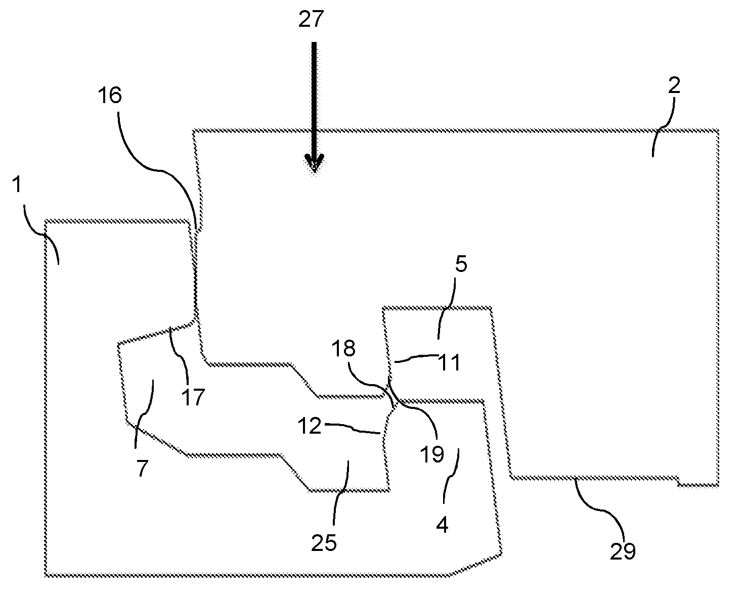
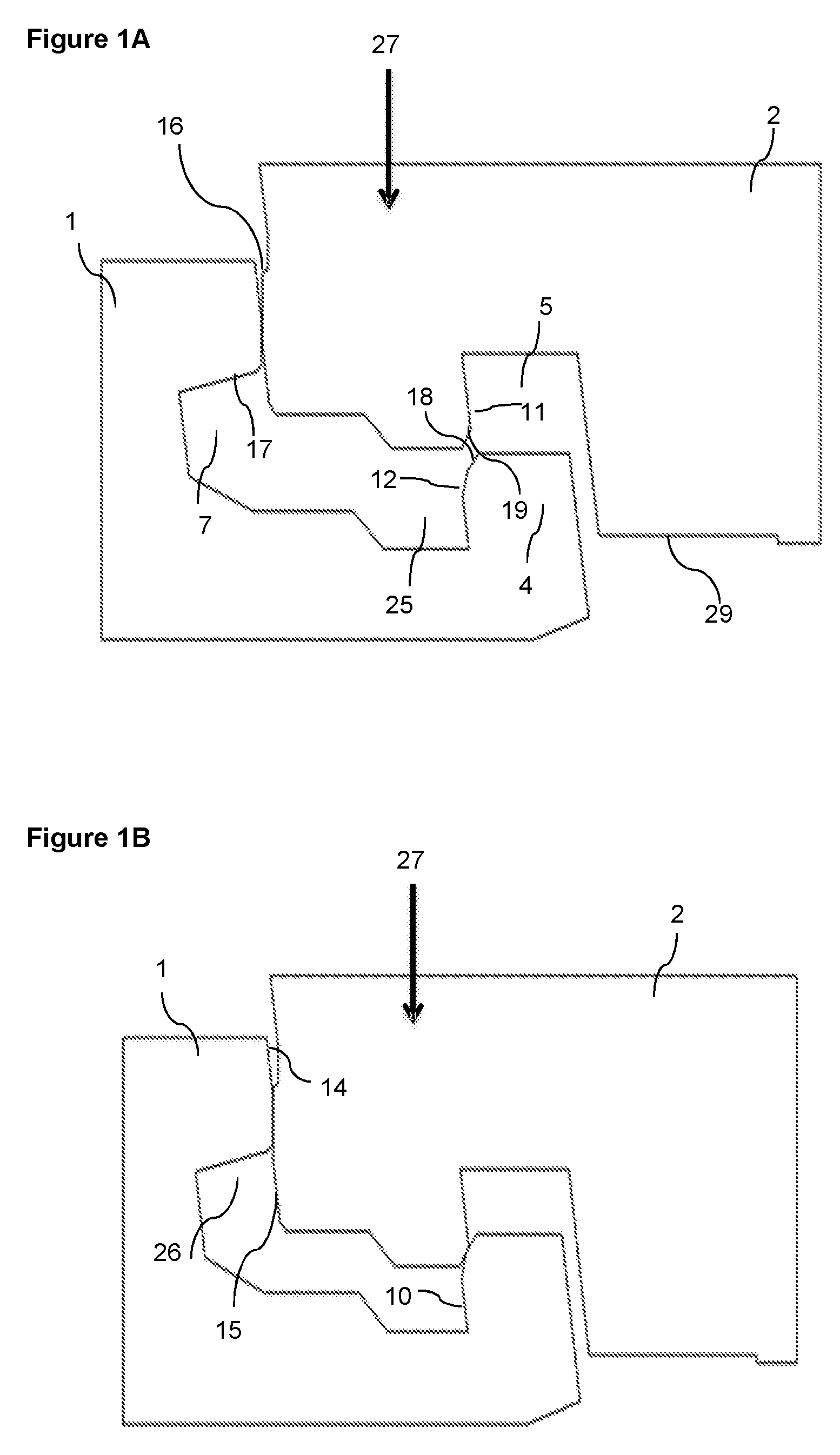
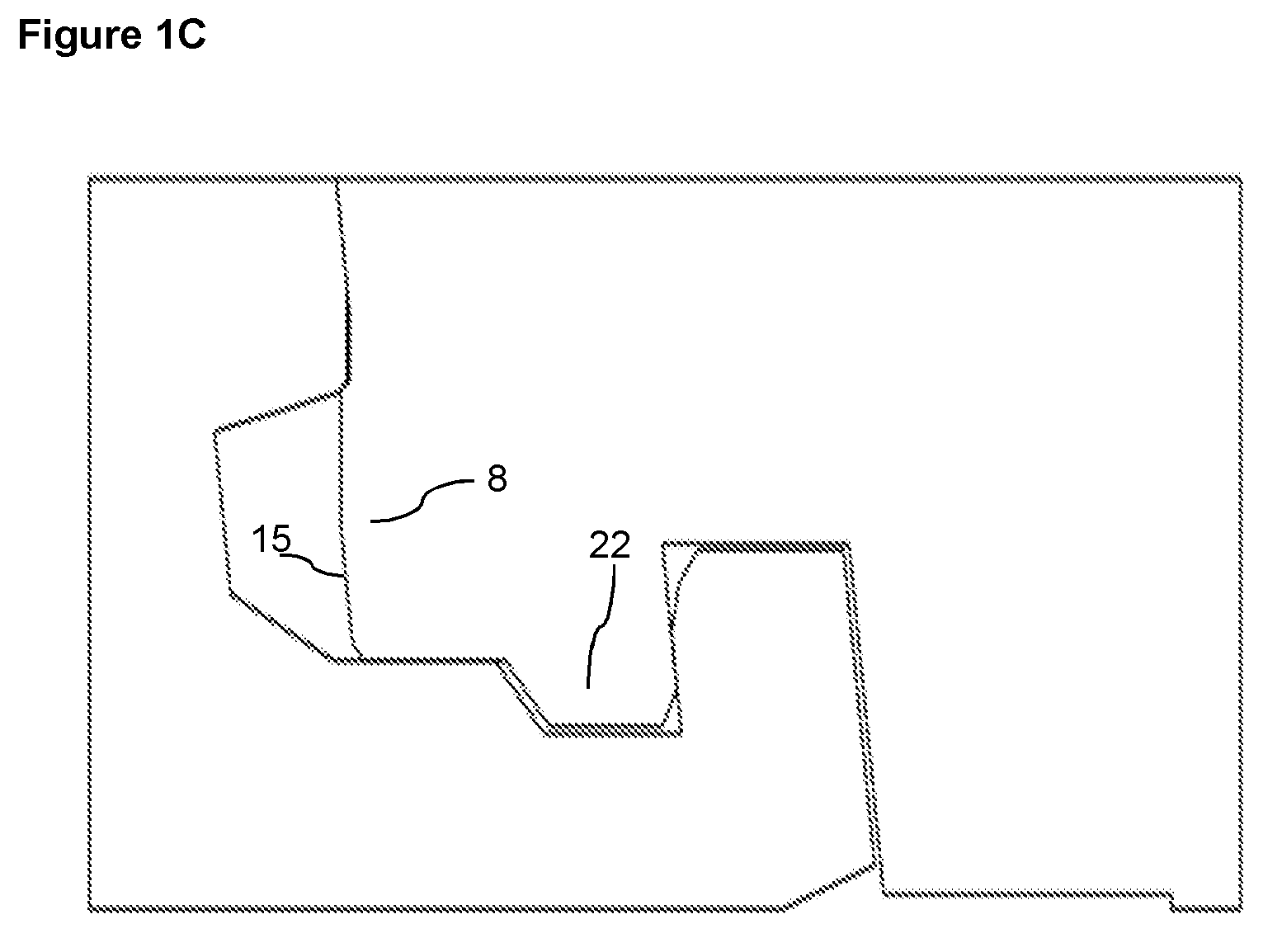
[0034] FIGS. 1A-1C show an embodiment of an assembling of an embodiment of a set of panels according to the invention, in which a first edge of a first panel and a second edge of a second panel are assembled.
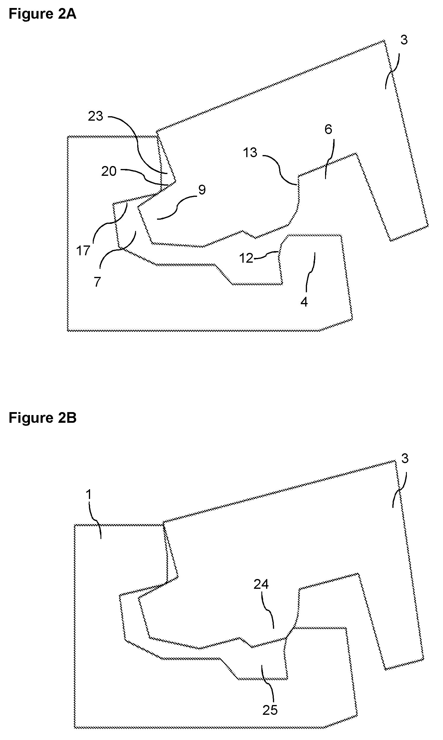
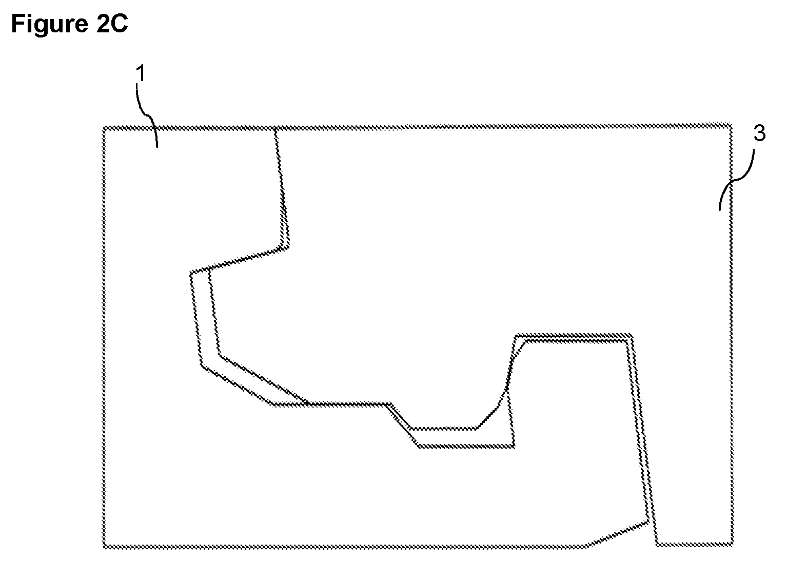
[0035] FIGS. 2A-2C show an embodiment of an assembling of an embodiment of a set of panels according to the invention, in which a first edge of a first panel and a third edge of a second panel are assembled.
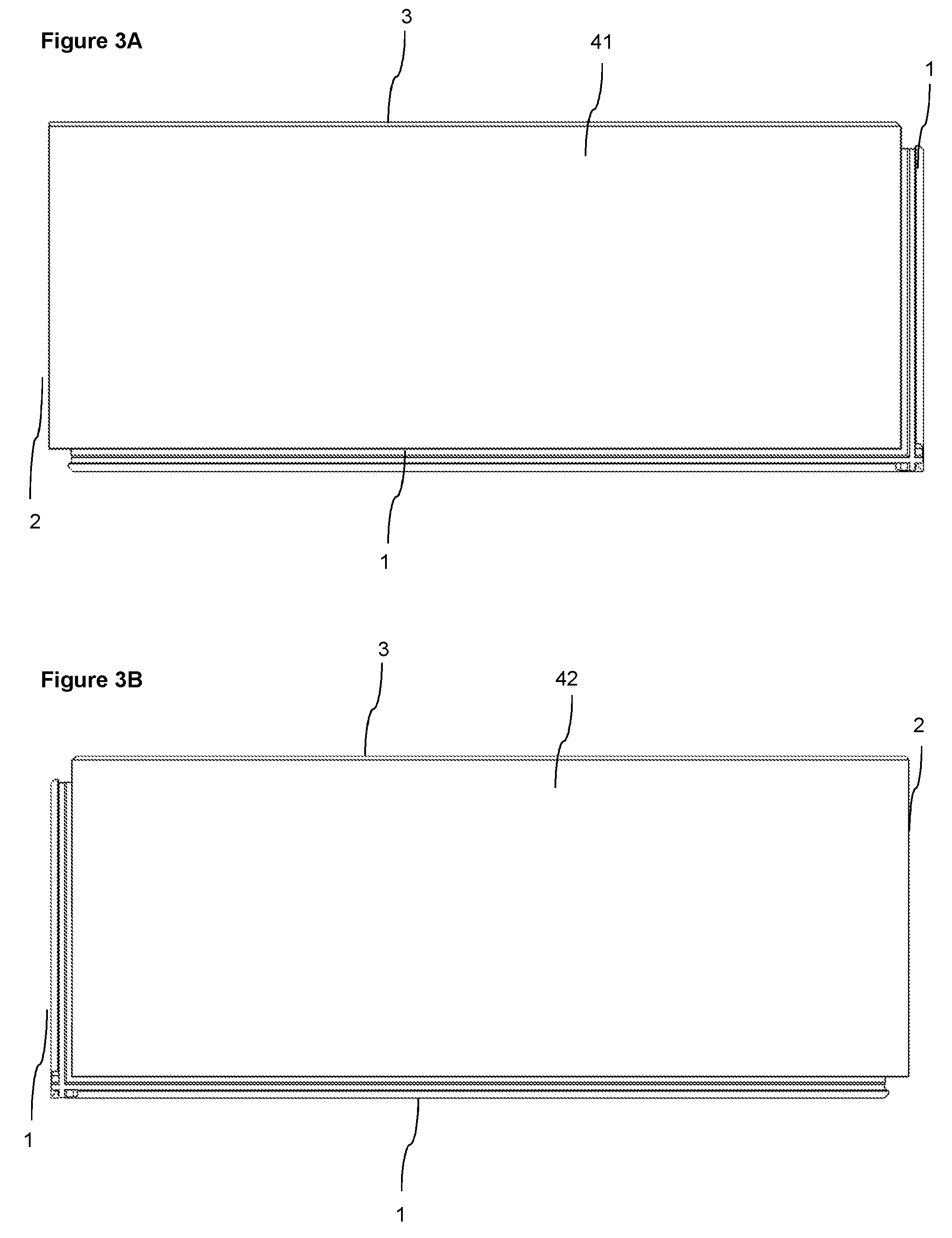
[0036] FIG. 3A shows an embodiment of a first panel according to the invention, comprising, in a clockwise direction starting from the edge to the right, the first edge, the first edge, the second edge, and the third edge.
[0037] FIG. 3B shows an embodiment of a second panel according to the invention, comprising, in a clockwise direction starting from the edge to the right, the second edge, the first edge, the first edge, and the third edge.
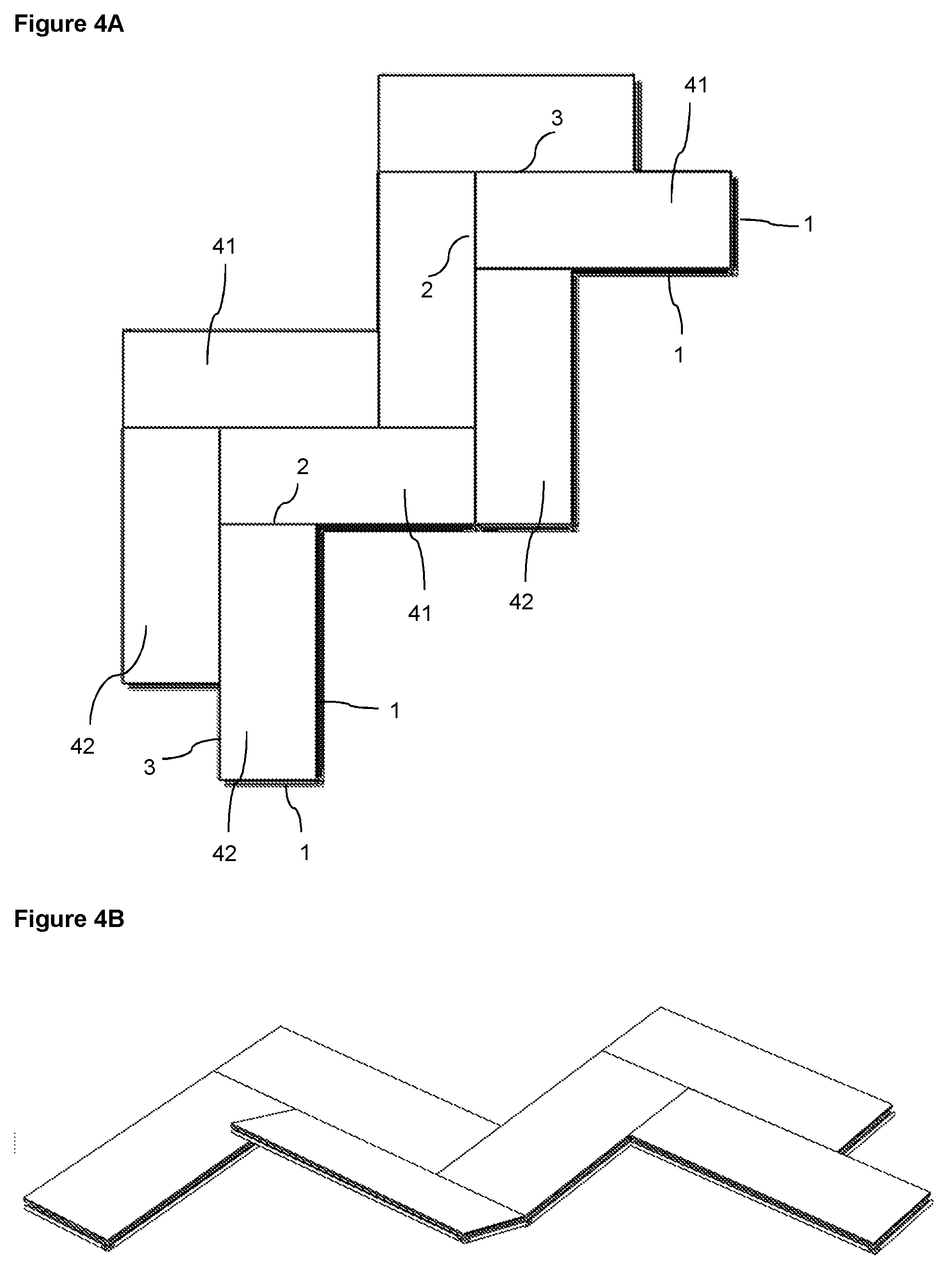
[0038] FIGS. 4A-4B show an embodiment of a set of panels according to the present invention, in which the panels are assembled in a herringbone pattern.
[0039] FIGS. 5A-5B show an embodiment in which panels according to the present invention are assembled in a modular pattern, i.e., parallel to each other. When assembling the panels in a modular pattern either only multiples of the first panel or only multiples of the second panel are to be connected to each other.
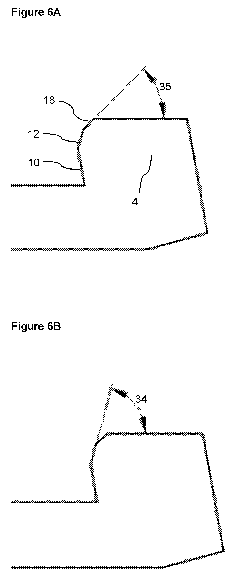
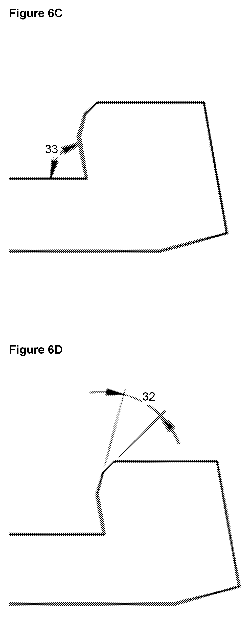
[0040] FIGS. 6A-6E show enlargements of the first locking element, illustrating angles between the different surfaces of the first locking element and also angles between the surfaces of the first locking element and an upper surface of the first or second panel.
DETAILED DESCRIPTION
[0041] Specific embodiments of the invention will now be described with reference to the accompanying drawings. This invention may, however, be embodied in many different forms and should not be construed as limited to the embodiments set forth herein; rather, these embodiments are provided so that this disclosure will be thorough and complete, and will fully convey the scope of the invention to those skilled in the art. The terminology used in the detailed description of the embodiments illustrated in the accompanying drawings is not intended to limit the invention. In the drawings, like numbers refer to like elements. When the word "about" is used in this specification in connection with a numerical value, it is intended that the associated numerical value include a tolerance of +/-10% around the stated numerical value.
[0042] An embodiment of the invention is shown during assembling in FIGS. 1A-1C. The embodiment comprises a set of panels comprising a first panel 41 and a second panel 42, as shown in FIGS. 3A and 3B, wherein a first edge 1 of the first panel 41 and a second edge 2 of the second panel 42 are configured to be locked together and assembled by a vertical displacement 27 of the second edge 2 of the second panel 42 relative to the first edge 1 of the first panel 41.
[0043] The first edge 1 comprises a first locking element 4 which is configured to be able to cooperate with a first locking groove 5 at the second edge 2, for locking in a horizontal direction. The first edge 1 also comprises a tongue groove 7 which is configured to cooperate with a tongue 8 at the second edge 2, for locking in a vertical direction. Further, the first locking element 4 comprises a first locking surface 10 which is configured to cooperate with a second locking surface 11 on the first locking groove 5, for locking in the horizontal and the vertical direction.
[0044] The first locking surface 10 may be parallel or essentially parallel to the second locking surface 11.
[0045] A first guiding surface 14 may be comprised on an upper part of the first edge 1, which first guiding surface 14 cooperates with a second guiding surface 15 on the lower edge of the tongue 8 during the vertical displacement 27.
[0046] The tongue 8 on the second edge 2 may comprise an upper locking surface 16 which is configured to cooperate for locking in a vertical direction with a lower locking surface 17 of an upper lip 26 of the tongue groove 7.
[0047] The locking element 4 may comprise a third guiding surface 18 and the locking groove 5 may comprise a fourth guiding surface 19. These features are configured to cooperate during the vertical displacement 27 of the second edge 2 relative to the first edge 1 for assembling the second edge 2 to the first edge 1, as shown in FIG. 1B.
[0048] The first guiding surface 14 may be parallel or essentially parallel to the second guiding surface 15.
[0049] The third guiding surface 18 may be parallel or essentially parallel to the fourth guiding surface 19.
[0050] The first and the second guiding surfaces 14,15 are configured to cooperate before the third and fourth guiding surfaces 18,19 during the vertical displacement.
[0051] The second edge 2 may comprise a second locking element 22 and the first edge 1 may comprise a third locking groove 25 which are configured to cooperate for locking in a horizontal direction.
[0052] The upper locking surface 16 is positioned above the second guiding surface 15.
[0053] The first locking surface 10 is positioned below the third guiding surface 18.
[0054] A locked position of the first edge 1 and the second edge 2 is shown in FIG. 1C. The first 1 and second edge 2 may be assembled by the vertical displacement 27.
[0055] The second edge 2 may include a lower groove 29 on the underside of the second edge 2. This lower groove 29 may provide a space to allow the second edge 2 to bend in order to allow the upper locking surface 16 and the lower locking surface 17 to lock together with greater ease.
[0056] The length of the second edge 2 is preferably shorter than the length of the first edge 1.
[0057] The vertical and horizontal lockings may be an advantage, especially for panels with a locking in a resilient material. The multiple vertical lockings may decrease the risk of unlocking and a separation of the first 1 and second 2 edges.
[0058] An embodiment of the invention is shown during assembling in FIGS. 2A-2C. The embodiment comprises a set of panels comprising a first panel 41 and a second panel 42, wherein a first edge 1 of the first panel 41 and a third edge 3 of the second panel 42 are configured to be locked together and assembled by an angling motion of the third edge 3 of the second panel 42 relative to the first edge 1 of the first panel 41.
[0059] The first edge 1 comprises a first locking element 4 which is configured to be able to cooperate with a second locking groove 6 at the third edge 3, for locking in a horizontal direction.
[0060] The first edge 1 also comprises a tongue groove 7 which is configured to cooperate with a tongue 9 at the third edge 3, for locking in a vertical direction. Further, the first locking element 4 comprises a third locking surface 12 which is configured to cooperate with a fourth locking surface 13 on the second locking groove 6, for locking in the horizontal direction.
[0061] The third locking surface 12 may be parallel or essentially parallel to the fourth locking surface 13.
[0062] The tongue 9 may comprise an upper locking surface 20 which is configured to cooperate for locking in a vertical direction with the lower locking surface 17 of the upper lip 26 of the tongue groove 7.
[0063] The third edge 3 may comprise a third locking element 24 configured to cooperate with a third locking groove 25 on the first edge 1 for locking in a horizontal direction.
[0064] The third edge 3 may be assembled to the first edge 1 by an angling motion, which is shown in FIGS. 2A and 2B.
[0065] The horizontal lockings as specified above may be an advantage, especially for panels with a locking in a resilient material. The multiple horizontal lockings may decrease the risk of unlocking and a separation of the first 1 and third 3 edges.
[0066] A locked position of the first edge 1 and the third edge 3 is shown in FIG. 2C.
[0067] The first locking surface 10 is positioned below the third locking surface 12.
[0068] The third locking surface 12 is positioned below the third guiding surface 18.
[0069] Enlargements of the first locking element 4 are shown in FIGS. 6A-6E.
[0070] An angle 31 between the first 10 and third 12 locking surface may be within the range of about 5.degree. to about 30.degree., preferably within the range of about 10.degree. to about 25.degree., or preferably about 17.degree..
[0071] An angle 32 between the third locking surface 12 and third guiding surface 18 may be within the range of about 10.degree. to about 40.degree., preferably within the range of about 20.degree. to about 30.degree., or preferably about 25.degree..
[0072] An angle 33 between the first locking surface 10 and an upper surface of the first 41 or second 42 panel may be within the range of about 70.degree. to about 85.degree., preferably within the range of about 75.degree. to about 80.degree., or preferably about 77.degree..
[0073] An angle 34 between the third locking surface 12 and an upper surface of the first 41 or second 42 panel may be within the range of about 50.degree. to about 85.degree., preferably within the range of about 60.degree. to about 75.degree., or preferably about 67.degree..
[0074] An angle 35 between the third guiding surface 18 and an upper surface of the first 41 or second 42 panel may be within the range of about 25.degree. to about 60.degree., preferably within the range of about 35.degree. to about 50.degree., or preferably about 42.degree..
[0075] The set of panels according to embodiments of the present invention may provide an increased locking strength of the panels due to the multiple locking surfaces. An improved locking together of the panels may be critical for keeping the panels in position, also when being subject to forces by subject matter in motion on the panels.
[0076] The set of panels according to embodiments of the present invention may also be easier to assemble compared to known sets of panels due to the guiding surfaces. An improved guiding may be critical for assembling panels having surfaces with a high friction and particularly, if the panel edges comprise a less elastic material. Without the improved guiding such panels may be difficult to assemble or the panels or part of the panel, e.g., the tongue may break during the assembling. The set of panels according to embodiments of the present invention also provide a more compact junction between panels and thereby a reduced amount of panel material going to waste.
[0077] The set of panels according to embodiments of the present invention may be assembled in different patterns. One example is a herringbone pattern, wherein a first 41 and second 42 panel are assembled, as shown in FIGS. 4A-4B. When assembling the panels in a herringbone pattern, the second edge 2 of the second panel 42 is to be connected vertically to the first edge 1 of the first panel 41.
[0078] Another example is a modular pattern, in which the panels are assembled parallel to each other, as shown in FIGS. 5A-5B. When assembling the panels in a modular pattern either only multiples of the first panel 41 or only multiples of the second panel 42 are to be connected to each other in each row of panels. When assembling the panels in a modular pattern, the first edge 1 of a first panel 41 is connected to the third edge 3 of a first panel 41, or, alternatively, the first edge 1 of a second panel 42 is connected to the third edge 3 of a second panel 42.
[0079] The first panel 41 may comprise, in a clockwise direction, the first edge 1, the first edge 1, the second edge 2, and the third edge 3, as shown in FIG. 3A.
[0080] The second panel 42 may comprise, in a clockwise direction, the second edge 2, the first edge 1, the first edge 1, and the third edge 3, as shown in FIG. 3B.
[0081] The first 41 panel and the second 42 panel may have a thickness in the range of about 3 mm to about 12 mm.
[0082] The embodiments described above may be resilient panels. The resilient panels may comprise a core comprising thermoplastic material. The thermoplastic material may be foamed.
[0083] The thermoplastic material may comprise polyvinyl chloride (PVC), polyester, polypropylene (PP), polyethylene (PE), polystyrene (PS), polyurethane (PU), polyethylene terephthalate (PET), polyacrylate, methacrylate, polycarbonate, polyvinyl butyral, polybutylene terephthalate, or a combination thereof. The core may be formed of several layers.
[0084] The embodiments described above may comprise a decorative layer, such as a decorative foil comprising a thermoplastic material. The thermoplastic material of the decorative layer may be or comprise polyvinyl chloride (PVC), polyester, polypropylene (PP), polyethylene (PE), polystyrene (PS), polyurethane (PU), polyethylene terephthalate (PET), polyacrylate, methacrylate, polycarbonate, polyvinyl butyral, polybutylene terephthalate, or a combination thereof. The decorative foil is preferably printed, for example by direct printing, rotogravure, or digital printing.
[0085] The embodiments described above may comprise a wear layer such as a film or foil. The wear layer may comprise thermoplastic material. The thermoplastic material may be polyvinyl chloride (PVC), polyester, polypropylene (PP), polyethylene (PE), polystyrene (PS), polyurethane (PU), polyethylene terephthalate (PET), polyacrylate, methacrylate, polycarbonate, polyvinyl butyral, polybutylene terephthalate, or a combination thereof.
[0086] The embodiments described above may comprise a wood base core, such as HDF, MDF or plywood.
[0087] The first panel and the second panel may be configured to be disassembled by downwardly rotating the first and/or the second panel.
EMBODIMENTS
[0088] 1. A set of panels comprising a first panel (41) and a second panel (42), said first (41) and second (42) panel each having a first edge (1), a second edge (2) and a third (3) edge and wherein the first edge (1) of the first panel (41) is configured to be able to be locked together with both the second (2) edge and the third (3) edge, respectively, of the second panel (42), [0089] wherein the first edge (1) comprises a first locking element (4) configured to be able to cooperate with a first locking groove (5) at the second edge (2) and a second locking groove (6) at the third edge (3), respectively, for locking in a horizontal direction, [0090] wherein the first edge (1) further comprises a tongue groove (7) configured to cooperate with a tongue (8) at the second edge (2) and a tongue (9) at the third edge (3), respectively, for locking in a vertical direction, [0091] wherein the first locking element (4) comprises a first locking surface (10) configured to cooperate with a second locking surface (11) on the first locking groove (5), for locking in the horizontal and the vertical direction, and [0092] wherein the first locking element (4) comprises a third locking surface (12) which is configured to cooperate with a fourth locking surface (13) on the second locking groove (6) for locking in the horizontal direction.
[0093] 2. The set of panels according to embodiment 1, wherein an upper part of the first edge (1) comprises a first guiding surface (14) and a lower edge of the tongue (8) of the second edge (2) comprises a second guiding surface (15), configured to cooperate during a vertical displacement (27) of the second edge (2) relative the first edge (1) for assembling the second edge (2) to the first edge (1).
[0094] 3. The set of panels according to embodiment 1 or 2, wherein the tongue (8) on the second edge (2) comprises an upper locking surface (16) which is configured to cooperate for locking in a vertical direction with a lower locking surface (17) of an upper lip (26) of the tongue groove (7).
[0095] 4. The set of panels according to any of the embodiments 1 to 3, wherein an upper part of the first locking element (4) comprises a third guiding surface (18) and a lower edge of the first locking groove (5) comprises a fourth guiding surface (19), configured to cooperate during the vertical displacement (27) of the second edge (2) relative to the first edge (1) for assembling the second edge (2) to the first edge (1).
[0096] 5. The set of panels according to any one of the embodiments 1 to 4, wherein the tongue (9) comprises an upper locking surface (20) which is configured to cooperate for locking in a vertical direction with the lower locking surface (17) of the upper lip (26) of the tongue groove (7).
[0097] 6. The set of panels according to any one of the embodiments 1 to 5, wherein an angle (31) between the first (10) and third (12) locking surface is within the range of about 5.degree. to about 30.degree., preferably within the range of about 10.degree. to about 25.degree., or preferably about 17.degree..
[0098] 7. The set of panels according to any one of the embodiments 4 to 6, wherein an angle (32) between the third locking surface (12) and third guiding surface (18) is within the range of about 10.degree. to about 40.degree., preferably within the range of about 20.degree. to about 30.degree., or preferably about 25.degree..
[0099] 8. The set of panels according to any one of the previous embodiments, wherein the second edge (2) comprises a second locking element (22) and the first edge (1) comprises a third locking groove (25), and wherein the second locking element and the third locking groove are configured to cooperate for locking in a horizontal direction.
[0100] 9. The set of panels according to any one of the previous embodiments, wherein the third edge (3) comprises a third locking element (24) configured to cooperate with the third locking groove (25) for locking in a horizontal direction.
[0101] 10. The set of panels according to any one of the previous embodiments, wherein the length of the second edge (2) is shorter than the length of the first edge (1).
[0102] 11. The set of panels according to any one of the previous embodiments, wherein the second edge (2) of the second panel (42) is to be connected vertically to the first edge (1) of the first panel (41).
[0103] 12. The set of panels according to any one of the previous embodiments, wherein the first panel (41) comprises, in a clockwise direction, the first edge (1), the first edge (1), the second edge (2), and the third edge (3).
[0104] 13. The set of panels according to any one of the previous embodiments, wherein the second panel (42) comprises, in a clockwise direction, the second edge (2), the first edge (1), the first edge (1), and the third edge (3).
[0105] 14. The set of panels according to any one of the previous embodiments, wherein the third edge (3) is configured to be assembled to the first edge (1) by an angling motion.
* * * * *
D00000
D00001
D00002
D00003
D00004
D00005
D00006
D00007
D00008
D00009
D00010
XML
uspto.report is an independent third-party trademark research tool that is not affiliated, endorsed, or sponsored by the United States Patent and Trademark Office (USPTO) or any other governmental organization. The information provided by uspto.report is based on publicly available data at the time of writing and is intended for informational purposes only.
While we strive to provide accurate and up-to-date information, we do not guarantee the accuracy, completeness, reliability, or suitability of the information displayed on this site. The use of this site is at your own risk. Any reliance you place on such information is therefore strictly at your own risk.
All official trademark data, including owner information, should be verified by visiting the official USPTO website at www.uspto.gov. This site is not intended to replace professional legal advice and should not be used as a substitute for consulting with a legal professional who is knowledgeable about trademark law.