Set Of Panels
BOO; Christian
U.S. patent application number 16/366173 was filed with the patent office on 2020-02-20 for set of panels. This patent application is currently assigned to VALINGE INNOVATION AB. The applicant listed for this patent is VALINGE INNOVATION AB. Invention is credited to Christian BOO.
| Application Number | 20200056379 16/366173 |
| Document ID | / |
| Family ID | 61757917 |
| Filed Date | 2020-02-20 |


| United States Patent Application | 20200056379 |
| Kind Code | A1 |
| BOO; Christian | February 20, 2020 |
SET OF PANELS
Abstract
A set of panels including a first panel and a second panel. A first edge of the first panel and a second edge of the second are configured to be locked together and assembled by a vertical displacement of the second edge relative the first edge. The first edge includes a locking element configured to cooperate with a locking groove at the second edge for locking in a horizontal and in the vertical direction. The first edge includes a tongue configured to cooperate with a tongue groove at the second edge for locking in a vertical direction. An upper part of the first edge includes a first guiding surface and a lower edge of the lower lip includes a second guiding surface. An upper part of the locking element includes a third guiding surface and a lower edge of the locking groove includes a fourth guiding surface.
| Inventors: | BOO; Christian; (Kagerod, SE) | ||||||||||
| Applicant: |
|
||||||||||
|---|---|---|---|---|---|---|---|---|---|---|---|
| Assignee: | VALINGE INNOVATION AB VIKEN SE |
||||||||||
| Family ID: | 61757917 | ||||||||||
| Appl. No.: | 16/366173 | ||||||||||
| Filed: | March 27, 2019 |
Related U.S. Patent Documents
| Application Number | Filing Date | Patent Number | ||
|---|---|---|---|---|
| 15404617 | Jan 12, 2017 | 10287777 | ||
| 16366173 | ||||
| Current U.S. Class: | 1/1 |
| Current CPC Class: | E04F 2201/04 20130101; E04F 15/02038 20130101; E04F 2201/042 20130101; E04F 2201/0146 20130101; E04F 15/02033 20130101; E04F 15/105 20130101 |
| International Class: | E04F 15/02 20060101 E04F015/02; E04F 15/10 20060101 E04F015/10 |
Foreign Application Data
| Date | Code | Application Number |
|---|---|---|
| Sep 30, 2016 | SE | 1651290-7 |
Claims
1-16. (canceled)
17. A set of panels comprising a first panel and a second panel, wherein a first edge of the first panel and a second edge of the second panel are configured to be locked together and assembled by a vertical displacement of the second edge relative the first edge, wherein the first edge comprises a locking element configured to cooperate with a locking groove at the second edge for locking in a horizontal direction, wherein the first edge comprises a tongue which comprises a first locking surface and the second edge comprises a tongue groove which comprises a second locking surface, wherein the first locking surface and the second locking surface are configured to cooperate for locking in a vertical direction, and wherein the first locking surface and the second locking surface are positioned at a distinguishing angle to each other in a locked position of the first and the second edge.
18. The set of panels as claimed in claim 17, wherein the distinguishing angle between the first locking surface and the second locking surface is in the range of about 5.degree. to about 15.degree..
19. The set of panels as claimed in claim 18, wherein the first locking surface has a first angle relative an upper surface of the first panel and the second locking surface has a second angle relative an upper surface of the second panel, and wherein the first angle is greater than the second angle.
20. The set of panels as claimed in claim 19, wherein the first angle is in the range of about 10.degree. to about 45.degree..
21. The set of panels as claimed in claim 19, wherein the second angle is in the range of about 10.degree. to about 45.degree..
22. The set of panels as claimed in claim 17, wherein the tongue groove has an upper lip and a lower lip, and wherein an upper part of the first edge comprises a first guiding surface and a lower edge of the lower lip comprises a second guiding surface, which are configured to cooperate during the vertical displacement.
23. The set of panels as claimed in claim 22, wherein the first guiding surface is a bevel or a rounding of an uppermost part of the first edge.
24. The set of panels as claimed in claim 17, wherein an upper part of the locking element comprises a third guiding surface and a lower edge of the locking groove comprises a fourth guiding surface, which are configured to cooperate during the vertical displacement.
25. The set of panels as claimed in claim 17, wherein a tip of the tongue comprises a fifth guiding surface and a tip of a lower lip of the tongue groove comprises a sixth guiding surface, which are configured to cooperate during the vertical displacement.
26. The set of panels as claimed in claim 25, wherein the fifth and the sixth guiding surfaces are essentially parallel to each other.
27. The set of panels as claimed in claim 25, wherein the first guiding surface is positioned above the fifth guiding surface.
28. The set of panels as claimed in claim 25, wherein the second guiding surface is positioned below the sixth guiding surface.
29. The set of panels as claimed in claim 17, wherein a locking strip protrudes from the first edge under the tongue, wherein the locking strip comprises the locking element.
30. The set of panels as claimed in claim 29, wherein a first locking surface of the locking element is configured to cooperate with a second locking surface of the locking groove for locking in the vertical and the horizontal direction, wherein a first locking angle between the first locking surface and an upper surface of the first panel is within the range of about 45.degree. to about 85.degree..
31. The set of panels as claimed in claim 17, wherein the tip of the tongue has a blunt shape.
32. The set of panels as claimed in claim 17, wherein a tip of the lower lip of the tongue groove has a blunt shape.
Description
CROSS REFERENCE TO RELATED APPLICATIONS
[0001] The present application is a continuation of U.S. application Ser. No. 15/404,617, filed on Jan. 12, 2017, which claims the benefit of Swedish Application No. 1651290-7, filed on Sep. 30, 2016. The entire contents of each of U.S. application Ser. No. 15/404,617 and Swedish Application No. 1651290-7 are hereby incorporated herein by reference in their entirety.
TECHNICAL FIELD
[0002] Embodiments of the present invention relates to panels, such as floorboards, which are configured to be locked together by a vertical displacement.
BACKGROUND
[0003] Panels are known that are configured to be assembled by a vertical displacement and to be locked together in a vertical direction and in a horizontal direction. Such panels are disclosed in, e.g., WO2014/182215. A tongue and groove connection locks a first edge of a first panel to a second edge of the second panel. The first and the second edge furthermore comprise a locking element configured to cooperate with a locking groove for locking in the vertical and the horizontal direction.
[0004] Embodiments of the present invention address a need to provide an easier assembling and/or an increased locking strength of the panels.
SUMMARY
[0005] It is an object of at least certain embodiments of the present invention to provide an improvement over the above described techniques and known art.
[0006] A further object of at least certain embodiments of the present invention is to facilitate assembling of panels configured to be assembled by a vertical displacement and locked together in the vertical direction and the horizontal direction.
[0007] Another object of at least certain embodiment of the present invention is to increase the locking strength by preventing or at least decreasing damage of edges of the panels, particularly parts of the edges that have a locking function. The locking strength may also be increased by an improved configuration of locking surfaces at the edges of the panels.
[0008] At least some of these and other objects and advantages that may be apparent from the description have been achieved by an aspect of the invention comprising a set of panels comprising a first panel and a second panel. The first edge of the first panel and a second edge of the second are configured to be locked together and assembled by a vertical displacement of the second edge relative the first edge. The first edge comprises a locking element configured to cooperate with a locking groove at the second edge for locking in a horizontal and in the vertical direction. The first edge comprises a tongue configured to cooperate with a tongue groove at the second edge for locking in a vertical direction. An upper part of the first edge comprises a first guiding surface and a lower edge of a lower lip of the tongue groove comprises a second guiding surface, which are configured to cooperate during the vertical displacement. An upper part of the locking element comprises a third guiding surface and a lower edge of the locking groove comprises a fourth guiding surface, which are configured to cooperate during the vertical displacement. A tip of the tongue comprises a fifth guiding surface and a tip of the lower lip of the tongue groove comprises a sixth guiding surface, which are configured to cooperate during the vertical displacement.
[0009] The three pairs of guiding surface may have the advantage that damages of particularly the tongue may be prevented during the vertical displacement.
[0010] The tongue at the first edge, at the same edge as the locking element, may provide an improved guiding and at the same time an improved configuration for the cooperation with the tongue groove.
[0011] The third and the fourth guiding surfaces and fifth and the sixth guiding surfaces, respectively, may be configure cooperate at the same time during the vertical displacement.
[0012] The first and the second guiding surfaces may be configured to cooperate at a first guiding position, during the vertical displacement, before a second guiding position comprising the guiding by the third and the fourth guiding surfaces. This may have the advantage that the second edge is in a correct position relative the first edge when edges are guided by the third and the fourth guiding surfaces and fifth and the sixth guiding surfaces. This second guiding position may occur at the same time as a bending of the locking strip and/or a compressing of parts of the first and the second edge in order to displace the first and the second edge to a locked position. The bending and the compression involve a stress of the first and the second edges. A correct position may decrease the stress.
[0013] The fifth and the sixth guiding surfaces may be essentially parallel, preferably parallel and/or essentially vertical, preferably vertical.
[0014] The first guiding surface may be positioned above the fifth guiding surface.
[0015] The second guiding surface may be positioned below the fifth guiding surface.
[0016] An upper lip of the tongue groove may be configured to overlap the first guiding surface in a locked position of the first and the second edge.
[0017] A lower surface of the upper lip may be configured cooperate with the first guiding surface for restraining penetration of moisture and/or dirt between the first and the second edge in the locked position.
[0018] The first guiding surface may be a bevel or a rounding of the uppermost part of the first edge.
[0019] The first guiding surface may be adjacent, preferably transition into, the fifth guiding surface. A close positioning of the first guiding surface and the fifth guiding surface may provide room for a larger guiding surface that may improve the guiding.
[0020] A locking strip may protrude from the first edge under the tongue, wherein the locking strip comprises the locking element.
[0021] A first locking surface of the locking element may be configured to cooperate with a second locking surface of the locking groove for locking in the vertical and the horizontal direction, wherein a first angle between the first locking surface and an upper surface of the first panel is preferably within the range of about 45.degree. to about 85.degree., preferably within the range of about 60.degree. to about 85.degree. or preferably about 80.degree..
[0022] The tip of the tongue may have a blunt shape which may improve the strength of the tip.
[0023] The tip of the lower lip of the tongue groove may have a blunt shape which may improve the strength of the tip.
[0024] The first edge and the second edge are preferably produced by mechanically cutting, such as milling.
[0025] The locking surfaces and the guiding surface may comprise a material of the core of the first panel and/or the second panel.
[0026] The first panel and the second panel may be resilient panels. The resilient panels may comprise a core comprising thermoplastic material. The thermoplastic material may be foamed.
[0027] The thermoplastic material may comprise polyvinyl chloride (PVC), polyester, polypropylene (PP), polyethylene (PE), polystyrene (PS), polyurethane (PU), polyethylene terephthalate (PET), polyacrylate, methacrylate, polycarbonate, polyvinyl butyral, polybutylene terephthalate, or a combination thereof. The core may be formed of several layers.
[0028] The first panel and the second panel may comprise a decorative layer, such as a decorative foil comprising a thermoplastic material. The thermoplastic material of the decorative layer may be or comprise polyvinyl chloride (PVC), polyester, polypropylene (PP), polyethylene (PE), polystyrene (PS), polyurethane (PU), polyethylene terephthalate (PET), polyacrylate, methacrylate, polycarbonate, polyvinyl butyral, polybutylene terephthalate, or a combination thereof. The decorative foil is preferably printed, for example by direct printing, rotogravure, or digital printing.
[0029] The firs panel and the second panel may comprise a wear layer such as a film or foil. The wear layer may comprise thermoplastic material. The thermoplastic material may be polyvinyl chloride (PVC), polyester, polypropylene (PP), polyethylene (PE), polystyrene (PS), polyurethane (PU), polyethylene terephthalate (PET), polyacrylate, methacrylate, polycarbonate, polyvinyl butyral, polybutylene terephthalate, or a combination thereof.
[0030] Embodiments of the invention may be particularly advantageous for panels comprising guiding surfaces with higher friction and a tongue comprising a less elastic thermoplastic material.
[0031] The first and the second panel may comprise a wood-based core, such as HDF, MDF or plywood.
[0032] The first guiding surface preferably extends through the decorative layer and/or the wear layer and a part of the first guiding surface comprises material of the core.
[0033] The first panel and the second panel may be configured to be disassembled by downwardly rotating the first and/or the second panel.
BRIEF DESCRIPTION OF THE DRAWINGS
[0034] These and other aspects, features and advantages of which embodiments of the invention are capable of, will be apparent and elucidated from the following description of embodiments of the present invention, reference being made to the accompanying drawings, in which
[0035] FIGS. 1A-1B show known panels configured to be locked together.
[0036] FIGS. 2A-2C show an embodiment of an assembling of an embodiment of a set of panels according to the invention.
[0037] FIGS. 3A-3C show an embodiment of an assembling of an embodiment of a set of panels according to the invention.
[0038] FIGS. 4A-4B show enlargements of edges of the panels shown in FIG. 2A-2C according to an embodiment of the invention.
[0039] FIGS. 4C-4D show enlargements of an embodiment of tongue and the lower lip, respectively.
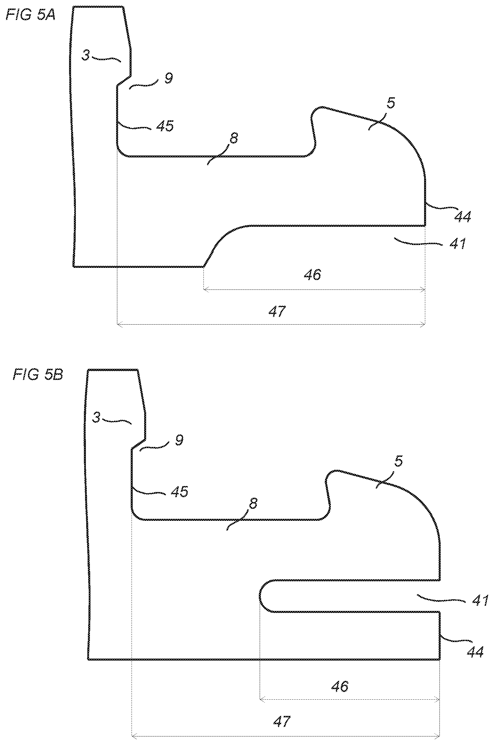
[0040] FIGS. 5A-5B show embodiments of an edge of a panel according to an embodiment of the invention.
[0041] FIGS. 6A-6B show embodiments of a set of panels according to embodiments of the invention.
[0042] FIGS. 7A-7B show embodiments of a set of panels according to embodiments of the invention.
[0043] FIG. 7C shows an enlargement of an embodiment of the locking surface of the tongue and of an embodiment of the locking surface of the tongue groove.
[0044] FIGS. 8A-8C show an embodiment of a set of panels according to an embodiment of the invention.
DESCRIPTION OF EMBODIMENTS
[0045] Specific embodiments of the invention will now be described with reference to the accompanying drawings. This invention may, however, be embodied in many different forms and should not be construed as limited to the embodiments set forth herein; rather, these embodiments are provided so that this disclosure will be thorough and complete, and will fully convey the scope of the invention to those skilled in the art. The terminology used in the detailed description of the embodiments illustrated in the accompanying drawings is not intended to be limiting of the invention. In the drawings, like numbers refer to like elements.
[0046] A known set of panels, such as floorboards, are shown in FIG. 1A-1B. The set comprising a first panel 51 and a second panel 52. A first edge of the first panel is configured to be locked to a second edge of the second panel. The first edge and the second edge is assembled by a relative vertical displacement 50. The first edge comprising a tongue groove 56 and the second edge comprises a tongue 53 which are configured for locking the first edge to the second edge in a vertical direction. The first edge comprises a protruding locking strip with locking element 55 which is configured to cooperate with a locking groove 58 at the second edge for locking in a horizontal direction and the vertical direction.
[0047] An embodiment of the invention is shown during assembling in FIG. 2A-2C. The embodiment comprises a set of panels comprising a first panel 1 and a second panel 2, wherein a first edge of the first panel and a second edge of the second panel are configured to be locked together and assembled by a vertical displacement 10 of the second edge relative the first edge. An enlargement of the first edge is shown in FIG. 4A and an enlargement of the second edge is shown in FIG. 4B.
[0048] The first panel and the second panel may have a thickness in the range of about 3 mm to about 12 mm.
[0049] The first edge comprises a locking element 5 configured to cooperate with a locking groove 4 at the second edge for locking in a horizontal direction and in the vertical direction. The first edge comprises a tongue 3 configured to cooperate with a tongue groove 6 at the second edge for locking in a vertical direction. The tongue groove 6 has an upper lip 7 and a lower lip 42. An upper part of the first edge comprises a first guiding surface 11 and a lower edge of the lower lip 42 comprises a second guiding surface 21, which are configured to cooperate during the vertical displacement. An upper part of the locking element comprises a third guiding surface 12 and a lower edge of the locking groove comprises a fourth guiding surface 22, which are configured to cooperate during the vertical displacement. A tip of the tongue comprises a fifth guiding surface 13 and a tip of a lower lip 42 of the tongue groove 6 comprises a sixth guiding surface 23, which are configured to cooperate during the vertical displacement. This embodiment of the invention may be easier to install compared to the known set of panels due to the guiding surfaces. An improved guiding may be critical for assembling panels having surfaces with a high friction and particularly if the panel edges comprise a less elastic material. Without the improved guiding such panels may be difficult to assemble or the panels or part of the panel, e.g., the tongue may break during the assembling.
[0050] A first guiding position is shown in FIG. 2A comprising the cooperation between the first guiding surface 11 and the second guiding surface 21.
[0051] A second guiding position is shown in FIG. 2B comprising the cooperation between the third guiding surface 12 and the fourth guiding surface 22, and the cooperation between the fifth guiding surface 13 the sixth guiding surface 23.
[0052] As is shown in FIG. 2A-2B the embodiment comprises three pairs of guiding surfaces, a first pair comprising the first guiding surface 11 and the second guiding surface 21, a second pair comprising the third guiding surface 12 and the fourth guiding surface 22, and a third pair comprising the fifth guiding surface 13 the sixth guiding surface 23.
[0053] The third guiding surface 12 and the fourth guiding surface 22 may be roundings. This embodiment may be advantageous for thinner panels with a thickness of about 3 mm to about 8 mm. The roundings may have a radius which is in the range of about 0.2 mm to about 0.4 mm, or about 0.3 mm. The radius may be in the range of about 5% to about 10% of the thickness of the panels.
[0054] The second edge may be provided with a calibrating groove 25 adjacent said locking groove 4. The calibrating groove may compensate for floorboards having different thickness, especially any difference in thickness at the edges of the floorboards. The calibrating groove allows that the second edge may be pushed towards a sub-floor on which the floorboards are arranged. The shown calibrating groove is of a rectangular shape, however the calibrating groove may have other shapes such as a bevel.
[0055] A locked position of the first edge and the second edge is shown in FIG. 2C.
[0056] A vertical locking both at the tongue and the tongue groove and at the locking element and the locking groove may be an advantage, especially for panels with a locking in a resilient material. The double vertical locking may decrease the risk of unlocking and a separation of the first and the second edges.
[0057] The tongue 3 may comprise a locking surface 33 at a lower side and the tongue groove may comprise a locking surface 34 at an upper side of the lower lip 42.
[0058] The locking surface 33 of the tongue 3 may be parallel or essentially parallel to the locking surface 34 of the tongue groove.
[0059] The tongue 3 at the first edge, at the same edge as the locking element, provides an improved guiding. Furthermore, the locking surfaces 33,34 at the tongue 3 and the lower lip 42 may be larger and at a more advantageous locking angle of the locking surfaces which may increase the locking strength as compared to known locking systems.
[0060] The third and the fourth guiding surfaces 12, 22 and fifth and the sixth guiding surfaces 13,23, respectively, are configure cooperate at the same time during the vertical displacement.
[0061] The first and the second guiding surfaces 11,21 are configured to cooperate before the third and the fourth guiding surfaces 12,22 during the vertical displacement.
[0062] The fifth and the sixth guiding surfaces 13,23 may be essentially parallel to each other, and preferably extend essentially vertical or may be within a range of about 1.degree. to about 5.degree., or about 2.degree. to the vertical direction.
[0063] The first guiding surface 11 is positioned above the fifth guiding surface 13.
[0064] The second guiding surface 21 is positioned below the sixth guiding surface 23.
[0065] An upper lip 7 of the tongue groove is configured to overlap the first guiding surface 11 in a locked position of the first and the second edge. A lower surface 24 of the upper lip 7 may be configured cooperate with the first guiding surface 11 for restraining penetration of moisture and/or dirt between the first and the second edge in the locked position.
[0066] The first guiding surface 11 may be a bevel or a rounding of the uppermost part of the first edge. The first guiding surface 11 may be adjacent, preferably transitions into, the fifth guiding surface 13.
[0067] A locking strip 8 protrudes from the first edge under the tongue 3 and the locking strip comprises the locking element 5.
[0068] A first locking surface 31 of the locking element 5 is configured to cooperate with a second locking surface 32 of the locking groove 4 for locking in the vertical and the horizontal direction.
[0069] A curved surface 49 which is between the first locking surface and an upper surface of the locking strip may be configured to cooperate in the locked position with the fourth guiding surface 22. This may further increase the locking strength in the horizontal direction.
[0070] A first locking angle 43 which is between the first locking surface 31 and an upper surface of the first panel may be within the range of about 45.degree. to about 85.degree., preferably within the range of about 60.degree. to about 85.degree., or preferably about 80.degree..
[0071] A second locking angle 40 which is between the second locking surface 32 and an upper surface of the second panel may be within the range of about 45.degree. to about 85.degree., preferably within the range of about 60.degree. to about 85.degree., or preferably about 80.degree., and may be essentially equal to the first locking angle 43.
[0072] An embodiment of the invention comprises a first locking angle 43 which is larger than the second locking angle, such as about 1-2.degree. larger. This may have the effect that a greater part of a pulling load is applied on curved surface cooperating with fourth guiding surface 22, and that a greater locking strength is obtained.
[0073] The locking element may have a first side, an opposite second side and an upper side. The first side is closer to the tongue 3 than the second side. The first locking surface is preferably at the first side. There may be a space between the second side and the locking groove 4. There may be a space between the upper side and the locking groove 4.
[0074] The tip of the tongue 3 may have a blunt shape which may improve the strength of the tip and improve the guiding. Each angle between adjacent surfaces, at the tip of the tongue, is preferably more than 90.degree..
[0075] FIG. 4C shows an embodiment of the tongue comprising a first tongue angle 91 between the first guiding surface 11 and the fifth guiding surface 13 and a second tongue angle 92 between the fifth guiding surface 13 and the locking surface 33 of the tongue. The first tongue angle 91 may be about 170.degree. or in the range of about 160.degree. to about 175.degree.. The second tongue angle 92 may be about 125.degree. or in the range of about 100.degree. to about 145.degree., for example in the range of about 110.degree. to about 145.degree..
[0076] A guiding angle between the first guiding surface 11 and the vertical direction may be about 10.degree. or in the range of about 5.degree. to about 20.degree..
[0077] The tip of the lower lip 42 of the tongue groove 6 may have a blunt shape which may improve the strength of the tip and improve the guiding. Each angle between adjacent surfaces, at the tip of the lower lip 42, is preferably more than 90.degree..
[0078] FIG. 4D shows an embodiment of the lower lip 42 comprising a first lip angle 93 between the locking surface 34 of the lower lip 42 and the sixth guiding surface 23 and a second lip angle 94 between the sixth guiding surface 23 and the second guiding surface 21. The first lip angle 93 may be about 125.degree. or in the range of about 100.degree. to about 145.degree., for example in the range of about 110.degree. to about 145.degree.. The second lip angle 94 may be about 170.degree. or in the range of about 160.degree. to about 175.degree..
[0079] FIG. 7C shows an embodiment of the locking surface 33 of the tongue 3 and the locking surface 34 of the tongue groove at the lower lip 42. Said locking surfaces 33,34 are poisoned at a distinguishing angle 97 to each other in the locked position. An advantage may be that locking surface 33 of the tongue may cooperate with the locking surface 34 of the tongue groove even if the locking surfaces are positioned incorrect due to production tolerances and/or dust or other particle between surfaces of the first edge and the second edge. In a locked position with an incorrect positioned locking surface, of the tongue and/or of the tongue groove, the locking strip may stay downwardly bent.
[0080] The distinguishing angle 97 between the locking surface 33 of the tongue 3 and the locking surface 34 of the tongue groove may be about 10.degree., or in the range of about 5.degree. to about 15.degree..
[0081] A first locking surface angle 99 is between the locking surface of the tongue and an upper surface of the first panel. A second locking surface angle 98 is between the locking surface 34 of the tongue groove and an upper surface of the second panel 2. The first locking surface angle 99 is preferably larger than the second surface angle 98.
[0082] The first locking surface angle 99 may be about 35.degree. or in the range of about 10.degree. to about 45.degree., or preferably in the range of about 20.degree. to about 40.degree..
[0083] The second locking surface angle 98 may be about 25.degree. or in the range of about 10.degree. to about 45.degree., or preferably in the range of about 20.degree. to about 40.degree..
[0084] An upper surface 36 of the locking strip may be configured to cooperate in a locked position with a lower surface 35 of the second edge.
[0085] The upper surface 36 of the locking strip may be essentially parallel to an upper surface of the first panel.
[0086] The upper surface 36 of the locking strip is preferably parallel to lower surface 35 of the second edge.
[0087] The first panel 1 and the second panel 2 may be configured to be disassembled by downwardly rotating 70 the first and/or the second panel, see FIG. 2C.
[0088] A lower side of the locking strip may comprise a space 41, such as a recess or bevel, under the locking element to facilitate bending of the locking strip during the assembling.
[0089] The first edge may comprise a lower groove 9 below the tongue 3. The lower lip 42 may be configured to be inserted into the lower groove 9 during the vertical displacement.
[0090] The assembling may comprise a displacement in the horizontal direction.
[0091] The firs edge and the second edge may be short edges of the first and the second panel.
[0092] The assembling may also comprise an angling motion along a long side of the first and or the second panel.
[0093] An embodiment of the set of panels is shown during assembling in FIG. 3A-3C. The third and the fourth guiding surfaces 12, 22 are in this embodiment bevels comprising an essentially flat surface. This embodiment may be advantageous for thicker panels and/or panels comprising a wood based core, such as HDF, MDF or plywood. The thicker panels may have a thickness in the range of about 7 mm to about 12 mm.
[0094] FIG. 5A-5B show embodiments of the first edge comprising a locking strip with a larger space 41. The first edge has a first distance 47 between a bottom surface 45 of the lower groove 9 and an outer surface 44 of the locking strip 8. The space 41 extends from outer surface 44 towards the bottom surface 45 by a second distance 46. The second distance may be within the range of about 1/10 to about equal the first distance, preferably about 1/10 to about 1/2 of the first distance, or more preferably 1/10 to about 1/3 of the first distance. The space 41 may have a height of 0.5 mm to 3 mm, preferably about 1 mm.
[0095] The space in the embodiment in FIG. 5A is a recess under the locking strip and the space in FIG. 5B is a groove in the locking strip 8. These embodiments may be advantageous for panels with a larger thickness.
[0096] The embodiments described above may be resilient panels. The resilient panels may comprise a core comprising thermoplastic material. The thermoplastic material may be foamed.
[0097] The thermoplastic material may comprise polyvinyl chloride (PVC), polyester, polypropylene (PP), polyethylene (PE), polystyrene (PS), polyurethane (PU), polyethylene terephthalate (PET), polyacrylate, methacrylate, polycarbonate, polyvinyl butyral, polybutylene terephthalate, or a combination thereof. The core may be formed of several layers.
[0098] The embodiments described above may comprise a decorative layer, such as a decorative foil comprising a thermoplastic material. The thermoplastic material of the decorative layer may be or comprise polyvinyl chloride (PVC), polyester, polypropylene (PP), polyethylene (PE), polystyrene (PS), polyurethane (PU), polyethylene terephthalate (PET), polyacrylate, methacrylate, polycarbonate, polyvinyl butyral, polybutylene terephthalate, or a combination thereof. The decorative foil is preferably printed, for example by direct printing, rotogravure, or digital printing.
[0099] The embodiments described above may comprise a wear layer such as a film or foil. The wear layer may comprise thermoplastic material. The thermoplastic material may be polyvinyl chloride (PVC), polyester, polypropylene (PP), polyethylene (PE), polystyrene (PS), polyurethane (PU), polyethylene terephthalate (PET), polyacrylate, methacrylate, polycarbonate, polyvinyl butyral, polybutylene terephthalate, or a combination thereof.
[0100] The embodiments described above may comprise a wood base core, such as HDF, MDF or plywood.
[0101] FIG. 6A shows that the first panel and the second panel may each comprise an upper layer 61, such as a decorative layer and/or wear layer. The first guiding surface 11 preferably extends through the upper layer 61 and a part of the first guiding surface comprises material of the core.
[0102] FIG. 6B shows that the first panel and the second panel may each comprise one or more enforcement layers 62 comprising, e.g., glass fiber. The enforcement layers 62 are preferably positioned outside the third and the fourth guiding surfaces 12, 22 and fifth and the sixth guiding surfaces 13,23. Enforcement layers at these guiding surfaces may increase the friction forces during assembling of the first panel and the second panel.
[0103] FIG. 7A shows that the second edge of the second panel 2 may comprise a second groove 71 adjacent the second locking surface 32. This groove 71 may facilitate disassembling by downwardly rotating 70 the first and/or the second panel
[0104] FIG. 7B shows that the first edge of the first panel 2 may comprise a first groove 72 adjacent the first locking surface 31. This groove 72 may facilitate disassembling by downwardly rotating 70 the first and/or the second panel
[0105] The first edge with the first groove 72 may be combined with the second edge with the second groove 71.
[0106] An embodiment of the first edge and the second edge is shown in FIG. 8A-8B. The embodiment includes a locking strip 8 which comprises a notch 82, adjacent the lower groove 9, which is configured to cooperate with a protrusion 81 at lower surface of the second edge and adjacent the lower lip. An advantage with the notch 82 and the protrusion 81 may be that the horizontal strength is further increased.
[0107] The notch 82 may comprise a notch surface 84 which may configured to cooperate for locking in the horizontal direction with a protrusion surface 83 of the protrusion 81. The notch surface 84 and the protrusion surface 83 are preferably parallel and arranged at angle 86 which is within the range of about 45.degree. to about 90.degree. to the upper surface of the first panel 1
[0108] The notch surface and the protrusion surface may be configured to be positioned at a distance 85 from each other, such as about 0.01 mm to about 0.1 mm, or about 0.05 mm, in the locked position. An advantage with the distance may be that assembling of the first panel and the second panel is facilitated.
[0109] In a further embodiment (not shown) the locking strip comprises the protrusion and the lower surface of the second edge comprises the notch.
* * * * *
D00000
D00001
D00002
D00003
D00004
D00005
D00006
D00007
D00008
XML
uspto.report is an independent third-party trademark research tool that is not affiliated, endorsed, or sponsored by the United States Patent and Trademark Office (USPTO) or any other governmental organization. The information provided by uspto.report is based on publicly available data at the time of writing and is intended for informational purposes only.
While we strive to provide accurate and up-to-date information, we do not guarantee the accuracy, completeness, reliability, or suitability of the information displayed on this site. The use of this site is at your own risk. Any reliance you place on such information is therefore strictly at your own risk.
All official trademark data, including owner information, should be verified by visiting the official USPTO website at www.uspto.gov. This site is not intended to replace professional legal advice and should not be used as a substitute for consulting with a legal professional who is knowledgeable about trademark law.