Resilient floor
Nilsson , et al. J
U.S. patent number 10,526,793 [Application Number 16/027,465] was granted by the patent office on 2020-01-07 for resilient floor. This patent grant is currently assigned to VALINGE INNOVATION AB. The grantee listed for this patent is VALINGE INNOVATION AB. Invention is credited to Mats Nilsson, Per Nygren.


| United States Patent | 10,526,793 |
| Nilsson , et al. | January 7, 2020 |
Resilient floor
Abstract
A method of assembling resilient floorboards is disclosed that includes the step of bending an edge of a floorboard during the assembling. The bending reduces the force required for connection of the edge to another edge of a juxtaposed floorboard. The floorboards may be provided with a mechanical locking system for vertical and horizontal locking of two adjacent floorboards.
| Inventors: | Nilsson; Mats (Viken, SE), Nygren; Per (Ramlosa, SE) | ||||||||||
|---|---|---|---|---|---|---|---|---|---|---|---|
| Applicant: |
|
||||||||||
| Assignee: | VALINGE INNOVATION AB (Viken,
SE) |
||||||||||
| Family ID: | 43646582 | ||||||||||
| Appl. No.: | 16/027,465 | ||||||||||
| Filed: | July 5, 2018 |
Prior Publication Data
| Document Identifier | Publication Date | |
|---|---|---|
| US 20180313093 A1 | Nov 1, 2018 | |
Related U.S. Patent Documents
| Application Number | Filing Date | Patent Number | Issue Date | ||
|---|---|---|---|---|---|
| 14982608 | Dec 29, 2015 | 10047527 | |||
| 14272895 | Feb 2, 2016 | 9249581 | |||
| 13734406 | Jun 24, 2014 | 8756899 | |||
| 12875293 | Feb 5, 2013 | 8365499 | |||
| 61239927 | Sep 4, 2009 | ||||
| Current U.S. Class: | 1/1 |
| Current CPC Class: | E04F 15/105 (20130101); E04F 15/02038 (20130101); E04F 15/10 (20130101); E04B 5/00 (20130101); Y10T 29/49623 (20150115); E04F 2201/0153 (20130101); E04F 2201/0138 (20130101); E04F 2201/0146 (20130101) |
| Current International Class: | E04F 15/02 (20060101); E04F 15/10 (20060101); E04B 5/00 (20060101) |
References Cited [Referenced By]
U.S. Patent Documents
| 3077703 | February 1963 | Bergstrom |
| 3120083 | February 1964 | Dahlberg et al. |
| 3247638 | April 1966 | Gay et al. |
| 3538665 | November 1970 | Gohner |
| 3619961 | November 1971 | Sterrett et al. |
| 3694983 | October 1972 | Couquet |
| 3720027 | March 1973 | Christensen |
| 3742669 | July 1973 | Mansfeld |
| 3760547 | September 1973 | Brenneman |
| 3857749 | December 1974 | Yoshida |
| 3919820 | November 1975 | Green |
| 4113399 | September 1978 | Hansen, Sr. et al. |
| 4172169 | October 1979 | Mawson et al. |
| 4176210 | November 1979 | Skinner |
| 4180615 | December 1979 | Bettoli |
| 4187131 | February 1980 | Shortway et al. |
| 4196554 | April 1980 | Anderson et al. |
| 4313866 | February 1982 | Renshaw |
| 4333987 | June 1982 | Kwart et al. |
| 4393187 | July 1983 | Boba et al. |
| 4423178 | December 1983 | Renshaw |
| 4426820 | January 1984 | Terbrack et al. |
| 4489115 | December 1984 | Layman et al. |
| 4507188 | March 1985 | Chu |
| 4512131 | April 1985 | Laramore |
| 4599841 | July 1986 | Haid |
| 4614680 | September 1986 | Fry et al. |
| 4772500 | September 1988 | Stroppiana |
| 4785065 | November 1988 | Uhl et al. |
| 4807412 | February 1989 | Frederiksen |
| 5007222 | April 1991 | Raymond |
| 5112671 | May 1992 | Diamond et al. |
| 5148850 | September 1992 | Urbanick |
| 5162141 | November 1992 | Davey et al. |
| 5182892 | February 1993 | Chase |
| 5274979 | January 1994 | Tsai |
| 5344700 | September 1994 | McGath et al. |
| 5380794 | January 1995 | Schaefer et al. |
| 5441677 | August 1995 | Phillips, Sr. |
| 5458953 | October 1995 | Wang et al. |
| 5465546 | November 1995 | Buse |
| 5548937 | August 1996 | Shimonohara |
| 5618602 | April 1997 | Nelson |
| 5630304 | May 1997 | Austin |
| 5670237 | September 1997 | Shultz et al. |
| 5694730 | December 1997 | Del Rincon et al. |
| 5797237 | August 1998 | Finkell, Jr. |
| 5950389 | September 1999 | Porter |
| 6006486 | December 1999 | Moriau et al. |
| 6052960 | April 2000 | Yonemura |
| 6065262 | May 2000 | Motta |
| 6101778 | August 2000 | Martensson |
| 6139945 | October 2000 | Krejchi et al. |
| 6173548 | January 2001 | Hamar et al. |
| 6182410 | February 2001 | Pervan |
| 6209278 | April 2001 | Tychsen |
| 6216409 | April 2001 | Roy et al. |
| 6233899 | May 2001 | Mellert et al. |
| 6291078 | September 2001 | Chen et al. |
| 6324809 | December 2001 | Nelson |
| 6332733 | December 2001 | Hamberger et al. |
| 6345481 | February 2002 | Nelson |
| 6363677 | April 2002 | Chen |
| 6455127 | September 2002 | Valtanen |
| 6490836 | December 2002 | Moriau et al. |
| 6505452 | January 2003 | Hannig |
| 6536178 | March 2003 | Palsson et al. |
| 6546691 | April 2003 | Leopolder |
| 6553724 | April 2003 | Bigler |
| 6558070 | May 2003 | Valtanen |
| 6617009 | September 2003 | Chen et al. |
| 6647690 | November 2003 | Martensson |
| 6672030 | January 2004 | Schulte |
| 6675545 | January 2004 | Chen et al. |
| 6715253 | April 2004 | Pervan |
| 6729091 | May 2004 | Martensson |
| 6761008 | July 2004 | Chen et al. |
| 6763643 | July 2004 | Martensson |
| 6766622 | July 2004 | Theirs |
| 6769218 | August 2004 | Pervan |
| 6769219 | August 2004 | Schwitte et al. |
| 6772568 | August 2004 | Thiers |
| 6790512 | September 2004 | MacQueen et al. |
| 6804926 | October 2004 | Eisermann |
| 6854235 | February 2005 | Martensson |
| 6862857 | March 2005 | Tychsen |
| 6865855 | March 2005 | Knauseder |
| 6874292 | April 2005 | Moriau |
| 6880307 | April 2005 | Schwitte |
| 6895881 | May 2005 | Whitaker |
| 6918220 | July 2005 | Pervan |
| 6928779 | August 2005 | Moriau et al. |
| 6986934 | January 2006 | Chen et al. |
| 7051486 | May 2006 | Pervan |
| 7090430 | August 2006 | Fletcher |
| 7121058 | October 2006 | Palsson et al. |
| 7127860 | October 2006 | Pervan et al. |
| 7155871 | January 2007 | Stone et al. |
| 7169460 | January 2007 | Chen et al. |
| 7171791 | February 2007 | Pervan |
| 7211310 | May 2007 | Chen et al. |
| 7251916 | August 2007 | Konzelmann et al. |
| 7275350 | October 2007 | Pervan et al. |
| 7337588 | March 2008 | Moebus |
| 7377081 | May 2008 | Ruhdorfer |
| 7398625 | July 2008 | Pervan |
| 7419717 | September 2008 | Chen et al. |
| 7454875 | November 2008 | Pervan et al. |
| 7484337 | February 2009 | Hecht |
| 7552568 | June 2009 | Palsson et al. |
| 7568322 | August 2009 | Pervan et al. |
| 7584583 | September 2009 | Bergelin et al. |
| 7603826 | October 2009 | Moebus |
| 7607271 | October 2009 | Griffin et al. |
| 7614197 | November 2009 | Nelson |
| 7617645 | November 2009 | Moriau et al. |
| 7617651 | November 2009 | Grafenauer |
| 7621094 | November 2009 | Moriau et al. |
| 7634886 | December 2009 | Moriau et al. |
| 7634887 | December 2009 | Moriau et al. |
| 7637066 | December 2009 | Moriau et al. |
| 7640708 | January 2010 | Moriau et al. |
| 7644555 | January 2010 | Moriau et al. |
| 7644557 | January 2010 | Moriau et al. |
| 7647743 | January 2010 | Moriau et al. |
| 7650728 | January 2010 | Moriau et al. |
| 7654054 | February 2010 | Moriau et al. |
| 7658048 | February 2010 | Moriau et al. |
| 7678215 | March 2010 | Martin |
| 7716896 | May 2010 | Pervan |
| 7739849 | June 2010 | Pervan |
| 7763345 | July 2010 | Chen et al. |
| 7779597 | August 2010 | Thiers |
| 7802415 | September 2010 | Pervan |
| 7841144 | November 2010 | Pervan |
| 7841150 | November 2010 | Pervan |
| 7856784 | December 2010 | Martensson |
| 7856789 | December 2010 | Eisermann |
| 7861482 | January 2011 | Pervan |
| 7874118 | January 2011 | Schitter |
| 7886497 | February 2011 | Pervan et al. |
| 7896571 | March 2011 | Hannig et al. |
| 7908816 | March 2011 | Grafenauer |
| 7930862 | April 2011 | Bergelin et al. |
| 7958689 | June 2011 | Lei |
| 7980043 | July 2011 | Moebus |
| 7984600 | July 2011 | Alford et al. |
| 8006460 | August 2011 | Chen et al. |
| 8021741 | September 2011 | Chen et al. |
| 8028486 | October 2011 | Pervan |
| 8033074 | October 2011 | Pervan et al. |
| 8042311 | October 2011 | Pervan et al. |
| 8071193 | December 2011 | Windmoller |
| 8091238 | January 2012 | Hannig et al. |
| 8099924 | January 2012 | Braun |
| 8112891 | February 2012 | Pervan |
| 8166718 | May 2012 | Liu |
| 8191333 | June 2012 | Braun |
| 8196366 | June 2012 | Thiers |
| 8234829 | August 2012 | Thiers et al. |
| 8245478 | August 2012 | Bergelin et al. |
| 8281549 | October 2012 | Du |
| 8293058 | October 2012 | Pervan et al. |
| 8302361 | November 2012 | Braun et al. |
| 8353140 | January 2013 | Pervan et al. |
| 8356452 | January 2013 | Thiers et al. |
| 8365499 | February 2013 | Nilsson et al. |
| 8375672 | February 2013 | Hannig |
| 8375674 | February 2013 | Braun |
| 8480841 | July 2013 | Pervan et al. |
| 8484924 | July 2013 | Braun |
| 8490361 | July 2013 | Curry et al. |
| 8499521 | August 2013 | Pervan et al. |
| 8511031 | August 2013 | Bergelin et al. |
| 8511040 | August 2013 | Braun et al. |
| 8544231 | October 2013 | Hannig |
| 8544232 | October 2013 | Wybo et al. |
| 8544234 | October 2013 | Pervan et al. |
| 8584423 | November 2013 | Pervan et al. |
| 8613826 | December 2013 | Pervan et al. |
| 8658274 | February 2014 | Chen et al. |
| 8689512 | April 2014 | Pervan |
| 8726604 | May 2014 | Hannig |
| 8745952 | June 2014 | Perra et al. |
| 8756899 | June 2014 | Nilsson et al. |
| 8763340 | July 2014 | Pervan et al. |
| 8800150 | August 2014 | Pervan |
| 8806832 | August 2014 | Kell |
| 8833028 | September 2014 | Whispell et al. |
| 8834992 | September 2014 | Chen et al. |
| 8952078 | February 2015 | Gould |
| 9103126 | August 2015 | Kell |
| 9212492 | December 2015 | Pervan et al. |
| 9222267 | December 2015 | Bergelin et al. |
| 9249581 | February 2016 | Nilsson et al. |
| 9296191 | March 2016 | Pervan et al. |
| 9314936 | April 2016 | Pervan |
| 9410328 | August 2016 | Pervan |
| 9528278 | December 2016 | Cappelle |
| 9695601 | July 2017 | Whispell et al. |
| 9714515 | July 2017 | Pervan |
| 9765530 | September 2017 | Bergelin et al. |
| 9777487 | October 2017 | Pervan et al. |
| 9856657 | January 2018 | Thiers |
| 10000935 | June 2018 | Kell |
| 10047527 | August 2018 | Nilsson et al. |
| 10059084 | August 2018 | Lundblad et al. |
| 10137659 | November 2018 | Pervan |
| 10287777 | May 2019 | Boo et al. |
| 10301830 | May 2019 | Boo |
| 10316526 | June 2019 | Kell |
| 10407919 | September 2019 | Boo |
| 2001/0021431 | September 2001 | Chen |
| 2002/0007606 | January 2002 | Kettler |
| 2002/0007608 | January 2002 | Pervan |
| 2002/0007609 | January 2002 | Pervan |
| 2002/0031646 | March 2002 | Chen |
| 2002/0069611 | June 2002 | Leopolder |
| 2002/0092263 | July 2002 | Schulte |
| 2002/0112433 | August 2002 | Pervan |
| 2002/0142135 | October 2002 | Chen et al. |
| 2002/0152707 | October 2002 | Martensson |
| 2002/0170258 | November 2002 | Schwitte et al. |
| 2002/0178674 | December 2002 | Pervan |
| 2002/0178681 | December 2002 | Zancai |
| 2002/0189183 | December 2002 | Ricciardelli |
| 2003/0009971 | January 2003 | Palmberg |
| 2003/0024199 | February 2003 | Pervan |
| 2003/0024200 | February 2003 | Moriau et al. |
| 2003/0037504 | February 2003 | Schwitte et al. |
| 2003/0041545 | March 2003 | Stanchfield |
| 2003/0084636 | May 2003 | Pervan |
| 2003/0101674 | June 2003 | Pervan et al. |
| 2003/0101681 | June 2003 | Tychsen |
| 2003/0110720 | June 2003 | Berard et al. |
| 2003/0180091 | September 2003 | Stridsman |
| 2003/0188504 | October 2003 | Eisermann |
| 2003/0196405 | October 2003 | Pervan |
| 2003/0224147 | December 2003 | Maine et al. |
| 2004/0031225 | February 2004 | Fowler |
| 2004/0031227 | February 2004 | Knauseder |
| 2004/0060255 | April 2004 | Knauseder |
| 2004/0068954 | April 2004 | Martensson |
| 2004/0128934 | July 2004 | Hecht |
| 2004/0137180 | July 2004 | Sjoberg et al. |
| 2004/0139678 | July 2004 | Pervan |
| 2004/0177584 | September 2004 | Pervan |
| 2004/0182036 | September 2004 | Sjoberg et al. |
| 2004/0206036 | October 2004 | Pervan |
| 2004/0211143 | October 2004 | Hannig |
| 2004/0211144 | October 2004 | Stanchfield |
| 2004/0219339 | November 2004 | Dempsey et al. |
| 2004/0241374 | December 2004 | Thiers |
| 2004/0250492 | December 2004 | Becker |
| 2004/0255538 | December 2004 | Ruhdorfer |
| 2004/0255541 | December 2004 | Thiers et al. |
| 2004/0261348 | December 2004 | Vulin |
| 2005/0003160 | January 2005 | Chen et al. |
| 2005/0028474 | February 2005 | Kim |
| 2005/0112320 | May 2005 | Wright |
| 2005/0138881 | June 2005 | Pervan |
| 2005/0144881 | July 2005 | Tate et al. |
| 2005/0166514 | August 2005 | Pervan |
| 2005/0176321 | August 2005 | Crette et al. |
| 2005/0193677 | September 2005 | Vogel |
| 2005/0208255 | September 2005 | Pervan |
| 2005/0210810 | September 2005 | Pervan |
| 2005/0221073 | October 2005 | Liou |
| 2005/0235593 | October 2005 | Hecht |
| 2005/0247000 | November 2005 | Zhu |
| 2005/0250921 | November 2005 | Qiu et al. |
| 2005/0252130 | November 2005 | Martensson |
| 2005/0268570 | December 2005 | Pervan |
| 2006/0010820 | January 2006 | Schwitte |
| 2006/0032168 | February 2006 | Thiers et al. |
| 2006/0032175 | February 2006 | Chen et al. |
| 2006/0053724 | March 2006 | Braun et al. |
| 2006/0070333 | April 2006 | Pervan |
| 2006/0101769 | May 2006 | Pervan et al. |
| 2006/0154015 | July 2006 | Miller et al. |
| 2006/0156666 | July 2006 | Caufield |
| 2006/0174974 | August 2006 | Brannstrom et al. |
| 2006/0225377 | October 2006 | Moriau et al. |
| 2006/0236642 | October 2006 | Pervan |
| 2006/0248830 | November 2006 | Moriau et al. |
| 2006/0248831 | November 2006 | Moriau et al. |
| 2006/0260252 | November 2006 | Brice |
| 2006/0260254 | November 2006 | Pervan |
| 2007/0006543 | January 2007 | Engstrom |
| 2007/0011981 | January 2007 | Eiserman |
| 2007/0022694 | February 2007 | Chen et al. |
| 2007/0028547 | February 2007 | Grafenauer et al. |
| 2007/0094986 | May 2007 | Moriau et al. |
| 2007/0094987 | May 2007 | Moriau et al. |
| 2007/0130872 | June 2007 | Goodwin |
| 2007/0151189 | July 2007 | Yang |
| 2007/0151191 | July 2007 | August |
| 2007/0154840 | July 2007 | Thies et al. |
| 2007/0175148 | August 2007 | Bergelin et al. |
| 2007/0175156 | August 2007 | Pervan et al. |
| 2007/0184230 | August 2007 | Verrue et al. |
| 2007/0193178 | August 2007 | Groeke et al. |
| 2007/0196624 | August 2007 | Chen et al. |
| 2007/0218252 | September 2007 | Donald |
| 2007/0275207 | November 2007 | Higgins et al. |
| 2008/0000182 | January 2008 | Pervan |
| 2008/0000183 | January 2008 | Bergelin et al. |
| 2008/0000186 | January 2008 | Pervan et al. |
| 2008/0000188 | January 2008 | Pervan |
| 2008/0010931 | January 2008 | Pervan et al. |
| 2008/0010937 | January 2008 | Pervan |
| 2008/0028707 | February 2008 | Pervan |
| 2008/0028713 | February 2008 | Pervan |
| 2008/0029490 | February 2008 | Martin, Jr. |
| 2008/0034701 | February 2008 | Pervan |
| 2008/0034708 | February 2008 | Pervan |
| 2008/0041007 | February 2008 | Pervan |
| 2008/0053028 | March 2008 | Moriau et al. |
| 2008/0060309 | March 2008 | Moriau et al. |
| 2008/0060310 | March 2008 | Moriau et al. |
| 2008/0092473 | April 2008 | Heyns |
| 2008/0104921 | May 2008 | Pervan et al. |
| 2008/0110125 | May 2008 | Pervan |
| 2008/0134607 | June 2008 | Pervan |
| 2008/0134613 | June 2008 | Pervan |
| 2008/0134614 | June 2008 | Pervan |
| 2008/0138560 | June 2008 | Windmoller |
| 2008/0141610 | June 2008 | Thiers |
| 2008/0148674 | June 2008 | Thiers et al. |
| 2008/0153609 | June 2008 | Kotler |
| 2008/0172971 | July 2008 | Pervan |
| 2008/0184646 | August 2008 | Alford |
| 2008/0241440 | October 2008 | Bauer |
| 2008/0256890 | October 2008 | Pervan |
| 2008/0311355 | December 2008 | Chen et al. |
| 2009/0019808 | January 2009 | Palsson et al. |
| 2009/0031662 | February 2009 | Chen et al. |
| 2009/0038253 | February 2009 | Martensson |
| 2009/0049787 | February 2009 | Hannig |
| 2009/0110888 | April 2009 | Wuest et al. |
| 2009/0133353 | May 2009 | Pervan |
| 2009/0151290 | June 2009 | Liu |
| 2009/0159156 | June 2009 | Walker |
| 2009/0186710 | July 2009 | Joseph |
| 2009/0193748 | August 2009 | Boo |
| 2009/0193753 | August 2009 | Schitter |
| 2009/0217611 | September 2009 | Schrader |
| 2009/0223162 | September 2009 | Chen et al. |
| 2009/0226662 | September 2009 | Dyczko-Riglin et al. |
| 2009/0235604 | September 2009 | Cheng et al. |
| 2009/0249733 | October 2009 | Moebus |
| 2009/0260313 | October 2009 | Segaert |
| 2009/0272058 | November 2009 | Duselis et al. |
| 2009/0320402 | December 2009 | Schacht et al. |
| 2010/0011695 | January 2010 | Cheng |
| 2010/0018149 | January 2010 | Thiers |
| 2010/0031594 | February 2010 | Liu |
| 2010/0043333 | February 2010 | Hannig et al. |
| 2010/0058702 | March 2010 | Lei |
| 2010/0260962 | October 2010 | Chen et al. |
| 2010/0293879 | November 2010 | Pervan et al. |
| 2010/0300029 | December 2010 | Braun et al. |
| 2010/0319293 | December 2010 | Dammers et al. |
| 2011/0001420 | January 2011 | Tchakarov et al. |
| 2011/0008567 | January 2011 | Weeks et al. |
| 2011/0030303 | February 2011 | Pervan et al. |
| 2011/0041996 | February 2011 | Pervan |
| 2011/0056167 | March 2011 | Nilsson et al. |
| 2011/0131901 | June 2011 | Pervan et al. |
| 2011/0131909 | June 2011 | Hannig |
| 2011/0138722 | June 2011 | Hannig |
| 2011/0146177 | June 2011 | Hannig |
| 2011/0154763 | June 2011 | Bergelin et al. |
| 2011/0167744 | July 2011 | Whispell et al. |
| 2011/0167751 | July 2011 | Engstrom |
| 2011/0247285 | October 2011 | Wybo |
| 2011/0247748 | October 2011 | Pervan et al. |
| 2011/0258959 | October 2011 | Braun |
| 2011/0296780 | December 2011 | Windmoller |
| 2012/0003439 | January 2012 | Chen et al. |
| 2012/0017534 | January 2012 | Oh |
| 2012/0040149 | February 2012 | Chen et al. |
| 2012/0067461 | March 2012 | Braun |
| 2012/0124932 | May 2012 | Schulte et al. |
| 2012/0137617 | June 2012 | Pervan |
| 2012/0180416 | July 2012 | Perra et al. |
| 2012/0216472 | August 2012 | Martensson |
| 2012/0266555 | October 2012 | Cappelle |
| 2012/0276369 | November 2012 | Jing et al. |
| 2012/0279154 | November 2012 | Bergelin et al. |
| 2013/0014890 | January 2013 | Pervan et al. |
| 2013/0042563 | February 2013 | Pervan et al. |
| 2013/0042565 | February 2013 | Pervan et al. |
| 2013/0047536 | February 2013 | Pervan |
| 2013/0111758 | May 2013 | Nilsson et al. |
| 2013/0160391 | June 2013 | Pervan et al. |
| 2013/0269863 | October 2013 | Pervan et al. |
| 2013/0298487 | November 2013 | Bergelin et al. |
| 2013/0333182 | December 2013 | Pervan et al. |
| 2014/0007539 | January 2014 | Pervan et al. |
| 2014/0033633 | February 2014 | Kell |
| 2014/0033635 | February 2014 | Pervan et al. |
| 2014/0069043 | March 2014 | Pervan |
| 2014/0069044 | March 2014 | Wallin |
| 2014/0115994 | May 2014 | Pervan |
| 2014/0237924 | August 2014 | Nilsson et al. |
| 2014/0283466 | September 2014 | Boo |
| 2014/0318061 | October 2014 | Pervan |
| 2014/0352248 | December 2014 | Whispell et al. |
| 2014/0356594 | December 2014 | Chen et al. |
| 2014/0366476 | December 2014 | Pervan |
| 2014/0366477 | December 2014 | Kell |
| 2015/0225964 | August 2015 | Chen et al. |
| 2015/0330088 | November 2015 | Derelov |
| 2015/0368910 | December 2015 | Kell |
| 2016/0016390 | January 2016 | Lundblad et al. |
| 2016/0016391 | January 2016 | Lundblad et al. |
| 2016/0052245 | February 2016 | Chen et al. |
| 2016/0069089 | March 2016 | Bergelin et al. |
| 2016/0076260 | March 2016 | Pervan et al. |
| 2016/0108624 | April 2016 | Nilsson et al. |
| 2016/0186318 | June 2016 | Pervan et al. |
| 2016/0194883 | July 2016 | Pervan |
| 2016/0194885 | July 2016 | Whispell et al. |
| 2016/0201324 | July 2016 | Hakansson et al. |
| 2016/0265234 | September 2016 | Pervan |
| 2017/0037642 | February 2017 | Boo |
| 2017/0037645 | February 2017 | Pervan |
| 2017/0175400 | June 2017 | Joseffson et al. |
| 2017/0241136 | August 2017 | Kell |
| 2017/0362834 | December 2017 | Pervan et al. |
| 2018/0094441 | April 2018 | Boo et al. |
| 2019/0091977 | March 2019 | Lundblad et al. |
| 2019/0211569 | July 2019 | Boo et al. |
| 2019/0249444 | August 2019 | Kell |
| 2019/0277041 | September 2019 | Pervan et al. |
| 2 252 791 | May 1999 | CA | |||
| 2456513 | Feb 2003 | CA | |||
| 2 252 791 | May 2004 | CA | |||
| 1270263 | Oct 2000 | CN | |||
| 101492950 | Jul 2009 | CN | |||
| 2 251 762 | May 1974 | DE | |||
| 198 54 475 | Jul 1999 | DE | |||
| 202 07 844 | Aug 2002 | DE | |||
| 20 2005 004 537 | Jun 2005 | DE | |||
| 10 2004 001 363 | Aug 2005 | DE | |||
| 198 54 475 | Jun 2006 | DE | |||
| 10 2005 024 366 | Nov 2006 | DE | |||
| 10 2005 061 099 | Mar 2007 | DE | |||
| 10 2006 024 184 | Nov 2007 | DE | |||
| 10 2006 058 655 | Jun 2008 | DE | |||
| 10 2006 058 655 | Jun 2008 | DE | |||
| 20 2008 011 589 | Nov 2008 | DE | |||
| 20 2008 012 001 | Nov 2008 | DE | |||
| 1 045 083 | Oct 2000 | EP | |||
| 1 165 906 | Jan 2002 | EP | |||
| 1 165 906 | Aug 2002 | EP | |||
| 1 045 083 | Oct 2002 | EP | |||
| 1 308 577 | May 2003 | EP | |||
| 1 350 904 | Oct 2003 | EP | |||
| 1 396 593 | Mar 2004 | EP | |||
| 1 420 125 | May 2004 | EP | |||
| 1 437 457 | Jul 2004 | EP | |||
| 1 437 457 | Jul 2004 | EP | |||
| 1 512 808 | Mar 2005 | EP | |||
| 1 585 875 | Oct 2005 | EP | |||
| 1 640 530 | Mar 2006 | EP | |||
| 1 585 875 | Oct 2006 | EP | |||
| 1 570 143 | May 2007 | EP | |||
| 1 938 963 | Jul 2008 | EP | |||
| 2 009 197 | Dec 2008 | EP | |||
| 2 327 502 | Oct 2009 | ES | |||
| 2 327 502 | Mar 2013 | ES | |||
| 1 293 043 | Apr 1961 | FR | |||
| 1 430 423 | Mar 1976 | GB | |||
| 1430423 | Mar 1976 | GB | |||
| S60-255843 | Dec 1985 | JP | |||
| H07-180333 | Jul 1995 | JP | |||
| H07-300979 | Nov 1995 | JP | |||
| H08-74405 | Mar 1996 | JP | |||
| 3363976 | Jan 2003 | JP | |||
| 1996-0005785 | Jul 1996 | KR | |||
| 10-2008-0096189 | Oct 2008 | KR | |||
| 10-0870496 | Nov 2008 | KR | |||
| 0000785 | Sep 2001 | SE | |||
| WO 94/26999 | Nov 1994 | WO | |||
| WO 96/27721 | Sep 1996 | WO | |||
| WO 98/58142 | Dec 1998 | WO | |||
| WO 00/20705 | Apr 2000 | WO | |||
| WO 00/47841 | Aug 2000 | WO | |||
| WO 01/02669 | Jan 2001 | WO | |||
| WO 01/02670 | Jan 2001 | WO | |||
| WO 01/02671 | Jan 2001 | WO | |||
| WO 01/44669 | Jun 2001 | WO | |||
| WO 01/44669 | Jun 2001 | WO | |||
| WO 01/48331 | Jul 2001 | WO | |||
| WO 01/48332 | Jul 2001 | WO | |||
| WO 01/51732 | Jul 2001 | WO | |||
| WO 01/51733 | Jul 2001 | WO | |||
| WO 01/53628 | Jul 2001 | WO | |||
| WO 01/66877 | Sep 2001 | WO | |||
| WO 01/75247 | Oct 2001 | WO | |||
| WO 01/77461 | Oct 2001 | WO | |||
| WO 01/88306 | Nov 2001 | WO | |||
| WO 01/98604 | Dec 2001 | WO | |||
| WO 01/02669 | Jan 2002 | WO | |||
| WO 02/103135 | Dec 2002 | WO | |||
| WO 03/012224 | Feb 2003 | WO | |||
| WO 03/016654 | Feb 2003 | WO | |||
| WO 03/025307 | Mar 2003 | WO | |||
| WO 03/035396 | May 2003 | WO | |||
| WO 03/038210 | May 2003 | WO | |||
| WO 03/044303 | May 2003 | WO | |||
| WO 03/085222 | Oct 2003 | WO | |||
| WO 03/089736 | Oct 2003 | WO | |||
| WO 2004/011740 | Feb 2004 | WO | |||
| WO 2004/016876 | Feb 2004 | WO | |||
| WO 2004/016877 | Feb 2004 | WO | |||
| WO 2004/050780 | Jun 2004 | WO | |||
| WO 2004/085765 | Oct 2004 | WO | |||
| WO 2005/088029 | Sep 2005 | WO | |||
| WO 2004/053256 | Oct 2005 | WO | |||
| WO 2005/098163 | Oct 2005 | WO | |||
| WO 2006/032378 | Mar 2006 | WO | |||
| WO 2006/043893 | Apr 2006 | WO | |||
| WO 2006/104436 | Oct 2006 | WO | |||
| WO 2006/123988 | Nov 2006 | WO | |||
| WO 2006/133690 | Dec 2006 | WO | |||
| WO 2007/015669 | Feb 2007 | WO | |||
| WO 2007/015669 | Feb 2007 | WO | |||
| WO 2007/016978 | Feb 2007 | WO | |||
| WO 2007/020088 | Feb 2007 | WO | |||
| WO 2004/044348 | May 2007 | WO | |||
| WO 2007/079845 | Jul 2007 | WO | |||
| WO 2007/118352 | Oct 2007 | WO | |||
| WO 2008/008016 | Jan 2008 | WO | |||
| WO 2008/008824 | Jan 2008 | WO | |||
| WO 2008/068245 | Jun 2008 | WO | |||
| WO 2008/116623 | Oct 2008 | WO | |||
| WO 2008/133377 | Nov 2008 | WO | |||
| WO 2009/033623 | Mar 2009 | WO | |||
| WO 2009/061279 | May 2009 | WO | |||
| WO 2009/071822 | Jun 2009 | WO | |||
| WO 2009/071822 | Jun 2009 | WO | |||
| WO 2010/015516 | Feb 2010 | WO | |||
| WO 2010/015516 | Feb 2010 | WO | |||
| WO 2010/023042 | Mar 2010 | WO | |||
| WO 2010/028901 | Mar 2010 | WO | |||
| WO 2010/072357 | Jul 2010 | WO | |||
| WO 2010/072357 | Jul 2010 | WO | |||
| WO 2010/081532 | Jul 2010 | WO | |||
| WO 2010/114236 | Oct 2010 | WO | |||
| WO 2010/128043 | Nov 2010 | WO | |||
| WO 2011/012104 | Feb 2011 | WO | |||
| WO 2011/012104 | Feb 2011 | WO | |||
| WO 2011/028171 | Mar 2011 | WO | |||
| WO 2011/077311 | Jun 2011 | WO | |||
| WO 2012/126046 | Sep 2012 | WO | |||
Other References
|
US. Appl. No. 14/224,628, Christian Boo, filed Mar. 25, 2014 (Cited herein as US Patent Application Publication No. 2014/0283466 A1 of Sep. 25, 2014). cited by applicant . U.S. Appl. No. 15/072,829, John M. Whispell and Hao A. Chen, filed Mar. 17, 2016 (Cited herein as US Patent Application Publication No. 2016/0194885 A1 of Jul. 7, 2016). cited by applicant . U.S. Appl. No. 15/333,630, Christian Boo, filed Oct. 25, 2016 (Cited herein as US Patent Application Publication No. 2017/0037642 A1 of Feb. 9, 2017). cited by applicant . U.S. Appl. No. 15/379,957, Per Josefsson and Christian Boo, filed Dec. 15, 2016 (Cited herein as US Patent Application Publication No. 2017/0175400 A1 of Jun. 22, 2017). cited by applicant . U.S. Appl. No. 15/404,617, Christian Boo, filed Jan. 12, 2017 (Cited herein as US Patent Application Publication No. 2018/0094441 A1 of Apr. 5, 2018). cited by applicant . U.S. Appl. No. 15/507,602, Richard William Kell, filed Feb. 28, 2017 (Cited herein as US Patent Application Publication No. 2017/0241136 A1 of Aug. 24, 2017). cited by applicant . U.S. Appl. No. 15/695,437, Darko Pervan and Marcus Nilsson Stahl, filed Sep. 5, 2017 (cited herein as US Patent Application Publication No. 2017/0362834 A1 of Dec. 21, 2017). cited by applicant . International Search Report issued in PCT/SE2010/050941, dated Nov. 1, 2010, Patent-och registreringsverket, Stockholm, SE, 5 pages. cited by applicant . Extended European Search Report issued in EP 10814032.8, dated Aug. 2, 2017, European Patent Office, Munich, DE, 9 pages. cited by applicant . Valinge Innovation AB, Technical Disclosure entitled "Mechanical locking for floor panels with Vertical Folding," IP.com No. IPCOM000179246D, Feb. 10, 2009, IP.com PriorArtDatabase, 59 pp. cited by applicant . Valinge Innovation AB, Technical Disclosure entitled "Mechanical locking for floor panels with a flexible bristle tongue," IP.com No. IPCOM000145262D, Jan. 12, 2007, IP.com PriorArtDatabase, 57 pages. cited by applicant . Complaint, Valinge Innovation AB v. Halstead New England Corp. and The Home Depot, Inc., United States District Court for the District of Delaware, Case No. 1-16-cv-01082, dated Nov. 23, 2016, 14 pages. cited by applicant . Second Amended Complaint, Valinge Innovation AB v. Halstead New England Corp., Halstead International; Home Depot U.S.A., Inc.; and The Home Depot, Inc., United States District Court for the District of Delaware, Case No. 16-1082-LPS-CJB, dated Mar. 28, 2017, 55 pages. cited by applicant . Lowe's, How to Install a Laminate Floor, YouTube video available for viewing at https://youtu.be/zhIXVHAejlk?t=3m52s, Oct. 2008 (last accessed Feb. 15, 2018). cited by applicant . Plaintiff's Opening Claim Construction Brief, Valinge Innovation AB v. Halstead New England Corp. and Home Depot U.S.A., Inc., United States District Court for the District of Delaware, C.A. No. 16-1082-LPS-CJB, dated Dec. 11, 2017, 38 pages (Document 86). cited by applicant . Declaration of Pilar G. Kraman in Support of Plaintiff's Opening Claim Construction Brief, with Exhibits 1-6, Valinge Innovation AB v. Halstead New England Corp. and Home Depot U.S.A., Inc., United States District Court for the District of Delaware, C.A. No. 16-1082-LPS-CJP, dated Dec. 11, 2017, 65 pages (Document 87, 87-1). cited by applicant . Declaration of Steven B. MacLean in Support of Plaintiff's Opening Claim Construction Brief, with Exhibits 1-2, Valinge Innovation AB v. Halstead New England Corp. and Home Depot U.S.A., Inc., United States District Court for the District of Delaware, C.A. No. 16-1082-LPS-CJB, dated Dec. 11, 2017, 23 pages (Document 88, 88-1, 88-2). cited by applicant . Defendants Halstead New England Corp. and Home Depot U.S.A., Inc.'s Opening Claim Construction Brief, Valinge Innovation AB v. Halstead New England Corp. and Home Depot U.S.A., Inc., United States District Court for the District of Delaware, C.A. No. 16-1082-LPS-CJB, dated Dec. 11, 2017, 36 pages (Document 89). cited by applicant . Declaration of Robert M Kimmel, Sc.D. on Claim Construction, with Exhibits A-Q, Valinge Innovation AB v. Halstead New England Corp. and Home Depot U.S.A., Inc., United States District Court for the District of Delaware, C.A. No. 16-1082-LPS-CJB, dated Dec. 11, 2017, 153 pages (Document 90, 90-1, 90-2). cited by applicant . Declaration of Richard T. Kaczkowski, with Exhibits A-D, Valinge Innovation AB v. Halstead New England Corp. and Home Depot U.S.A., Inc., United States District Court for the District of Delaware, C.A. No. 16-1082-LPS-CJB, dated Dec. 11, 2017, 48 pages (Document 91, 91-1). cited by applicant . Exhibits 1-17 (re Document 89), Valinge Innovation AB v. Halstead New England Corp. and Home Depot U.S.A., Inc., United States District Court for the District of Delaware, C.A. No. 16-1082-LPS-CJB, dated Dec. 11, 2017, 381 pages (Document 92, 92-1). cited by applicant . Plaintiff's Responsive Claim Construction Brief, Valinge Innovation AB v. Halstead New England Corp. and Home Depot U.S.A., Inc., United States District Court for the District of Delaware, C.A. No. 16-1082-LPS-CJB, dated Jan. 16, 2018, 29 pages (Document 98). cited by applicant . Declaration of Pilar G. Kraman in Support of Plaintiff's Responsive Claim Construction Brief, with Exhibits 1-15, Valinge Innovation AB v. Halstead New England Corp. and Home Depot U.S.A., Inc., United States District Court for the District of Delaware, C.A. No. 16-1082-LPS-CJB, dated Jan. 16, 2018, 105 pages (Document 99, 99-1). cited by applicant . Declaration of Steven B. MacLean in Support of Plaintiff's Responsive Claim Construction Brief, Valinge Innovation AB v. Halstead New England Corp. and Home Depot U.S.A., Inc., United States District Court for the District of Delaware, C.A. No. 16-1082-LPS-CJB, dated Jan. 16, 2018, 25 pages (Document 100). cited by applicant . Defendants Halstead New England Corp. and Home Depot U.S.A., Inc.'s Responsive Claim Construction Brief, Valinge Innovation AB v. Halstead New England Corp. and Home Depot U.S.A., Inc., United States District Court for the District of Delaware, C.A. No. 16-1082-LPS-CJB, dated Jan. 16, 2018, 26 pages (Document 102, 102-1). cited by applicant . Declaration of Brian A. Biggs in Support of Defendants Halstead New England Corp. And Home Depot U.S.A., Inc.'s Responsive Claim Construction Brief, with Exhibit 1, Valinge Innovation AB v. Halstead New England Corp. and Home Depot U.S.A., Inc., United States District Court for the District of Delaware, C.A. No. 16-1082-LPS-CJB, dated Jan. 16, 2018, 6 pages (Document 103, 103-1, 103-2). cited by applicant . Supplemental Declaration of Robert M. Kimmel, Sc.D. on Claim Construction, with Exhibits A-J, Valinge Innovation AB v. Halstead New England Corp. and Home Depot U.S.A., Inc., United States District Court for the District of Delaware, C.A. No. 16-1082-LPS-CJB, dated Jan. 16, 2018, 69 pages (Document 104, 104-1, 104-2). cited by applicant . Memorandum Opinion, Valinge Innovation AB v. Halstead New England Corp. and Home Depot U.S.A., Inc., United States District Court for the District of Delaware, C.A. No. 16-1082-LPS-CJB, dated May 7, 2018, 19 pages (Document 162). cited by applicant . Order, Valinge Innovation AB v. Halstead New England Corp. and Home Depot U.S.A., Inc., United States District Court for the District of Delaware, C.A. No. 16-1082-LPS-CJB, dated May 7, 2018, 2 pages (Document 163). cited by applicant . Third Amended Complaint, Valinge Innovation AB v. Halstead New England Corp. and Home Depot U.S.A., Inc., United States District Court for the District of Delaware, C.A. No. 16-1082-LPS-CJB, dated Jul. 10, 2018, 69 pages (Document 214). cited by applicant . Defendant Halstead New England Corp.'s Answer to the Third Amended Complaint, Affirmative Defenses and Counterclaim--Valinge Innovation AB v. Halstead New England Corp. and Home Depot U.S.A., Inc., United States District Court for the District of Delaware, C.A. No. 16-1082-LPS-CJB, dated Aug. 8, 2018, 172 pages (Document 242, 242-1, 242-2, 242-3--Redacted Version of Document 230). cited by applicant . Joint Motion for Entry of Partial Summary Judgment--Valinge Innovation AB v. Halstead New England Corp. and Home Depot U.S.A., Inc., United States District Court for the District of Delaware, C.A. No. 16-1082-LPS-CJB, dated Sep. 13, 2018, 4 pages (Document 262). cited by applicant . Order of Partial Summary Judgment--Valinge Innovation AB v. Halstead New England Corp. and Home Depot U.S.A., Inc., United States District Court for the District of Delaware, C.A. No. 16-1082-LPS-CJB, dated Sep. 13, 2018, 2 pages (Document 262-1). cited by applicant . U.S. Appl. No. 16/366,173, Christian Boo, filed Mar. 27, 2019. cited by applicant . U.S. Appl. No. 16/392,931, Richard William Kell, filed Apr. 24, 2019. cited by applicant . U.S. Appl. No. 16/366,173, Boo. cited by applicant . U.S. Appl. No. 16/392,931, Kell. cited by applicant . Boo, Christian, U.S. Appl. No. 16/366,173 entitled "Set of Panels," filed in the U.S. Patent and Trademark Office on Mar. 27, 2019. cited by applicant . Kell, Richard William, U.S. Appl. No. 16/392,931, entitled "Vertical Joint System for a Surface Covering Panel," filed in the U.S. Patent and Trademark Office on Apr. 24, 2019. cited by applicant . U.S. Appl. No. 16/220,748, Christian Boo, Marcus Nilsson Stahl and Anders Nilsson, filed Dec. 14, 2018. cited by applicant . U.S. Appl. No. 16/253,465, Darko Pervan and Marcus Nilsson Stahl, filed Jan. 22, 2019. cited by applicant . U.S. Appl. No. 16/220,748, Boo, et al. cited by applicant . U.S. Appl. No. 16/253,465, Pervan et al. cited by applicant . Boo, Christian, et al., U.S. Appl. No. 16/220,748, entitled "Set of Panels," filed in the U.S. Patent and Trademark Office on Dec. 14, 2018. cited by applicant . Pervan, Darko, et al., U.S. Appl. No. 16/253,465 entitled "Mechanical Locking of Floor Panels with Vertical Snap Folding," filed in the U.S. Patent and Trademark Office on Jan. 22, 2019. cited by applicant . **Boo, Christian, U.S. Appl. No. 16/528,992 entitled "Floorboards Provided With a Mechanical Locking System," filed in the U.S. Patent and Trademark Office on Aug. 1, 2019. cited by applicant. |
Primary Examiner: Figueroa; Adriana
Attorney, Agent or Firm: Buchanan Ingersoll & Rooney P.C.
Parent Case Text
CROSS-REFERENCE TO RELATED APPLICATIONS
This application is a continuation of U.S. application Ser. No. 14/982,608, filed on Dec. 29, 2015, which is a continuation of U.S. application Ser. No. 14/272,895, filed on May 8, 2014, now U.S. Pat. No. 9,249,581, which is a continuation of U.S. application Ser. No. 13/734,406, filed on Jan. 4, 2013, now U.S. Pat. No. 8,756,899, which is a continuation of U.S. application Ser. No. 12/875,293, filed on Sep. 3, 2010, now U.S. Pat. No. 8,365,499, which claims benefit to U.S. Provisional Application No. 61/239,927, filed Sep. 4, 2009. The entire contents of U.S. application Ser. No. 14/982,608, U.S. application Ser. No. 14/272,895, U.S. application Ser. No. 13/734,406, U.S. application Ser. No. 12/875,293 and U.S. Provisional Application No. 61/239,927 are each hereby incorporated by reference in its entirety.
Claims
The invention claimed is:
1. A method of assembling resilient floorboards, which are provided with a mechanical locking system for vertical and horizontal locking of two adjacent floorboards, wherein the method comprises the step of: positioning a first edge of a first floorboard, provided with a first device of said mechanical locking system, juxtaposed a second edge of a second floorboard, provided with a second device of said mechanical locking system; bending the first floorboard along the first edge; and applying a force on a first part of the first edge, wherein at said first part of the first edge said first device is pushed into said second device to obtain a vertical and horizontal mechanical locking of a part of the first and second edges, wherein the first device comprises a downwardly protruding locking element and the second device comprises an upwardly protruding locking element, wherein the downwardly protruding locking element is provided with an angled first locking surface configured to cooperate with an angled second locking surface of the upwardly protruding locking element of the adjacent floorboard for locking, the first edge vertically and horizontally with the second edge of the adjacent floorboard, the first device further comprises an upper upwardly resiliently bendable locking strip configured to form a convex shape towards a bottom surface of the floorboard during locking, wherein the first device further comprises a locking groove configured to form a tight fit with the upwardly protruding locking element, wherein the angled first locking surface is configured to contact the angled second locking surface of the upwardly protruding locking element, and wherein a first surface of the locking groove opposite the angled first locking surface is configured to contact a second surface of the upwardly protruding locking element opposite the angled second locking surface, wherein the first edge comprises a first top edge and the second edge comprises a second top edge, wherein a surface of the first top edge and a surface of the second top edge are vertical, wherein the floorboards each include a core made of a thermoplastic material, and wherein the upper upwardly resiliently bendable locking strip comprises a lower surface between the angled first locking surface and the first surface, wherein the upwardly protruding locking element and the lower surface are configured to be in contact when the floorboard and an adjacent floorboard are vertically and horizontally locked.
2. The method according to claim 1, wherein the method comprises the step of applying a force to a new part of the first edge, which new part is adjacent to said first part, and repeating this step until the whole first edge is vertically and horizontally locked to said second edge.
3. The method according to claim 1, wherein the force is applied by a tool.
4. The method according to claim 1, wherein the method comprises the step of connecting an adjacent edge of the first floorboard to a juxtaposed edge of a third floorboard in another row by angling.
5. The method according to claim 1, wherein a lower locking strip of the second device is downwardly resiliently bendable.
6. The method according to claim 1, wherein the downwardly protruding locking element is provided with a first guiding surface, which is configured to cooperate with the upwardly protruding locking element.
7. The method according to claim 6, wherein the first guiding surface cooperates with a second guiding surface of the upwardly protruding locking element.
8. The method according to claim 6, wherein the angle of the first guiding surface is more than about 30.degree..
9. The method according to claim 6, wherein the angle of the first guiding surface is more than about 45.degree..
10. The method according to claim 7, wherein the angle of said second guiding surface is more than about 30.degree..
11. The method according to claim 7, wherein the angle of said second guiding surface is more than about 45.degree..
12. The method according to claim 1, wherein the angle between the first and second locking surfaces and the upper surface of the floorboards is more than 90.degree. to obtain a vertical locking in a position where the first and second locking surfaces cooperate.
13. The method according to claim 1, wherein the first edge is provided with a tongue and the second edge is provided with a groove for vertical locking of the floorboards.
14. The method according to claim 1, wherein the first edge is provided with a groove and the second edge provided with a tongue for vertical locking of the floorboards.
15. A set of resilient floorboards, each floorboard provided with a mechanical locking system for vertical and horizontal locking to an adjacent floorboard, the mechanical locking system comprising a first device at a first edge, and a second device at a second edge, wherein the first device comprises a downwardly protruding locking element and the second device comprises an upwardly protruding locking element, wherein the downwardly protruding locking element is provided with an angled first locking surface configured to cooperate with an angled second locking surface of the upwardly protruding locking element of the adjacent floorboard for locking the first edge vertically and horizontally with the second edge of the adjacent floorboard, the first device further comprises an upper upwardly resiliently bendable locking strip configured to form a convex shape towards a bottom surface of the first floorboard during locking, wherein the first device further comprises a locking groove configured to form a tight fit with the upwardly protruding locking element, wherein the angled first locking surface is configured to contact the angled second locking surface of the upwardly protruding locking element, and wherein a first surface of the locking groove opposite the angled first locking surface is configured to contact a second surface of the upwardly protruding locking element opposite the angled second locking surface, wherein the first edge comprises a first top edge and the second edge comprises a second top edge, wherein a surface of the first top edge and a surface of the second top edge are vertical, wherein the floorboards each include a core made of a thermoplastic material, and wherein the upper upwardly resiliently bendable locking strip comprises a lower surface between the angled first locking surface and the first surface, wherein the upwardly protruding locking element and the lower surface are configured to be in contact when the floorboard and an adjacent floorboard are vertically and horizontally locked.
16. The set of resilient floorboards according to claim 15, wherein a lower locking strip of the second device is downwardly resiliently bendable.
17. The set of resilient floorboards according to claim 15, wherein an outermost side of the downwardly protruding locking element comprises at least an angled lower wall that angles inwards towards the upwardly protruding locking element of the adjacent floorboard.
18. The set of resilient floorboards according to claim 15, wherein the downwardly protruding locking element is provided with a first guiding surface configured to cooperate with the upwardly protruding locking element.
19. The set of resilient floorboards according to claim 18, wherein the upwardly protruding locking element is provided with a second guiding surface configured to cooperate with the first guiding surface.
20. The set of resilient floorboards according to claim 18, wherein the angle of the first guiding surface is more than about 30.degree..
21. The set of resilient floorboards according to claim 18, wherein the angle of the first guiding surface is more than about 45.degree..
22. The set of resilient floorboards according to claim 19, wherein the angle of the second guiding surface is more than about 30.degree..
23. The set of resilient floorboards according to claim 19, wherein the angle of the second guiding surface is more than about 45.degree..
24. The set of resilient floorboards according to claim 15, the angle between the first locking surface and the second locking surface and an upper surface of the floorboards is more than 90.degree. to obtain a vertical locking in a position where the first locking surface and the second locking surface cooperate.
25. The set of resilient floorboards according to claim 15, wherein the downwardly protruding locking element is provided with a guiding surface configured to cooperate with an upper edge of the adjacent floorboard.
26. The set of resilient floorboards according to claim 15, wherein the first edge is provided with a tongue and the second edge is provided with a groove for vertical locking of the floorboards.
27. The set of resilient floorboards according to claim 15, wherein the first edge is provided with a groove and the second edge is provided with a tongue for vertical locking of the floorboards.
28. The set of resilient floorboards according to claim 15, wherein the upper upwardly resiliently bendable locking strip and the lower locking strip are integrally formed in the floorboard.
29. The set of resilient floorboards according to claim 15, wherein the floorboards are comprised of resilient material and the mechanical locking system is integrally formed in one piece with the resilient material of each floorboard.
30. The set of resilient floorboards according to claim 15, wherein the core of each floorboard includes the first and second devices.
31. The set of resilient floorboards according to claim 15, wherein the angled first locking surface forms a first acute angle with the lower surface, and the angled second locking surface forms a second acute angle with an upper surface of a lower locking strip of the second device.
Description
TECHNICAL FIELD
The present invention generally concerns a method of assembling of floorboards provided with a mechanical locking system.
BACKGROUND OF THE INVENTION
Floorboards with a wood based core that are provided with a mechanical locking system and methods of assembling such floorboards by angling-angling, angling-snapping or vertical folding are disclosed in e.g. WO 94/26999, WO 01/77461, WO 2006/043893 and WO 01/75247. Floorboards of resilient material, e.g. PVC, are known, commonly referred to as LVT (Luxury Vinyl Tiles) that are glued down to the subfloor or bonded at the edges to each other WO 2008/008824.
SUMMARY OF THE INVENTION
A method is disclosed for assembling of floorboards, which are so called resilient floorboards i.e. the core is of a resilient material for example vinyl or PVC. The known methods of assembling floorboards that are mentioned above are difficult to use when assembling resilient floorboards since resilient floorboards easily bend which make it hard to use the angling-angling method and it is unfeasible to use the angling-snapping method since it requires a force to be applied, at an opposite edge in relation to the edge of the floorboard which is intended to be connected, by e.g. a hammer and a tapping block and the resilient core of the resilient floorboard absorbs the applied force. The known vertical folding methods are also difficult to apply due to the increased friction in the resilient material. The disclosed method makes the assembling easier and reduces the force needed for connection of the floorboards.
Furthermore, a locking system suitable for the method is disclosed. The locking system decreases the friction forces that must be overcome when installing the resilient floorboards.
An aspect of the invention is a method of assembling resilient floorboards, which are provided with a mechanical locking system, which method comprises the step of: positioning a floorboard edge, provided with a first device of said mechanical locking system (11), juxtaposed another floorboard edge, provided with a second device of said mechanical locking system (11); bending (30) the floorboard (2) along the edge; and applying a force (F) on a first part of the floorboard edge, wherein at said first part of the floorboard edge said first device is pushed into said second device to obtain a vertical and horizontal mechanical locking of a part of the floorboards' edges.
The bending makes it possible to finalize the connection of only a part of the edge of the floorboard, instead of the whole edge as in the known methods, and consequently the force needed to assemble the floorboards is considerably reduced.
The bending is preferably achieved by raising an outer part of said edge preferably by positioning of a raising device, e.g. a wedge, or a hand/finger of the assembler under said floorboard. The raised position of the outer part of said edge is preferably maintained during the force-applying step. In a preferred embodiment also the position of the raising device is maintained during the force-applying step.
The method comprises thereafter preferably the step of applying a force to a new part of the edge, which new part is adjacent to the mechanically locked part, and repeating this step until the whole edge is connected to said another edge.
The force is preferably applied by a tool and most preferably by a tool with a rotatable part.
In a preferred embodiment, the first device is an upper locking strip, which is resiliently bendable, with a downwardly protruding locking element and the second device is a lower locking strip provided with an upwardly protruding locking element. The resiliently bendable locking strip facilitates the connection of the floorboards. The downwardly protruding locking element is provided with a locking surface, which cooperates, for horizontal locking, with a locking surface of the upwardly protruding locking element. The locking strips are integrally formed with the resilient floorboards and preferably of the same resilient material. The downwardly and/or the upwardly protruding locking element is preferably provided with a guiding surface which are configured to guide the locking elements in to a position where the floorboards are connected by the locking elements and the locking surfaces cooperate.
The resilient floorboards are in a preferred embodiment made of a bendable thermo plastic, e.g. vinyl, surlyn, and PVC. Floorboards of vinyl are generally referred to as LVT (Luxury Vinyl Tiles). In a most preferred embodiment the thickness of the floorboard is about 4 mm to about 10 mm. If the floorboards are too thin it is hard to produce a locking system integrally in the floorboard material and if they are too thick it is hard to assemble the floorboards with the disclosed method.
The floorboards are in a preferred embodiment provided with an upper decorative layer made of a similar resilient material and most preferably provided with a balancing layer and/or a sublayer.
The force is preferably applied with a tool, which comprises a handle and a press part for applying a force on the floorboard. Preferably, the press part is provided with an outer round or circular shape for applying the force on the floorboard and in the most preferred embodiment the press part is rotatable.
BRIEF DESCRIPTION OF THE DRAWINGS
FIGS. 1a-b show an embodiment of the assembling method.
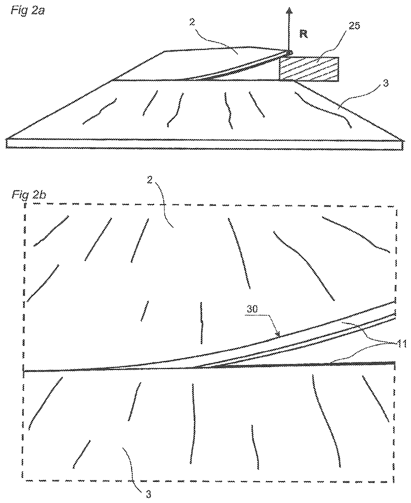
FIGS. 2a-2b show an embodiment of the assembling method.
FIGS. 3a-3b show embodiments of the assembling method.
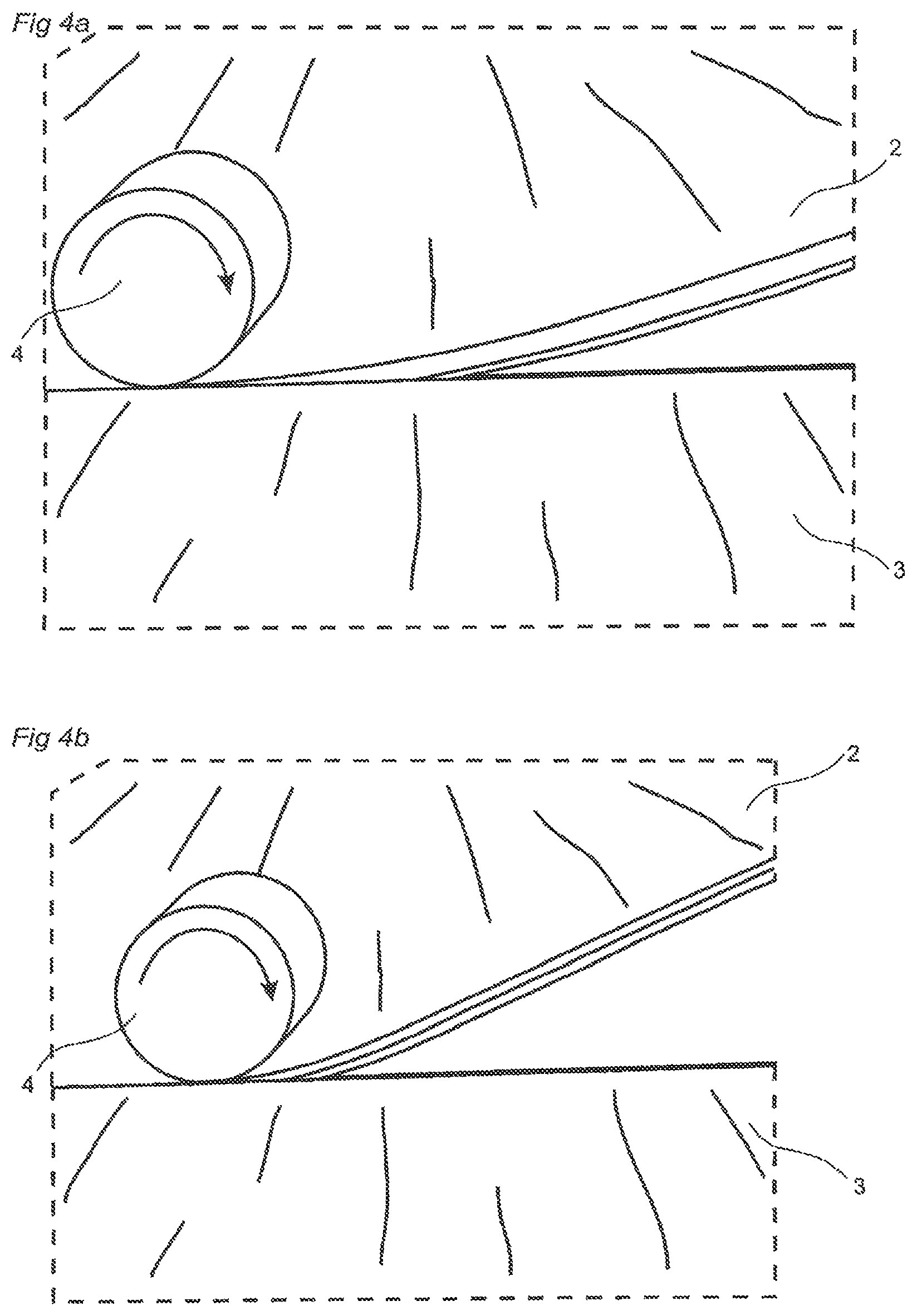
FIGS. 4a-4b show embodiments of the assembling method.
FIGS. 5a-5b show an embodiment of a locking system configured for connection by angling.
FIGS. 6a-6c show an embodiment of resilient floorboards during assembling.
FIGS. 7a-c show embodiments of a locking system for resilient floorboards.
FIGS. 8a-8c show embodiments of a locking system for resilient floorboards
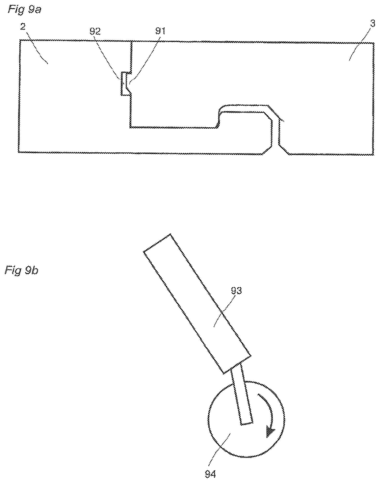
FIGS. 9a-b show an embodiment of a locking system and an embodiment of the assembling tool.
DETAILED DESCRIPTION OF EMBODIMENTS
An embodiment of a method of assembling resilient floorboards (1, 2, 3) with a mechanical locking system 11 is shown in FIGS. 1a and 1b. An edge of a floorboard 2 is positioned juxtaposed another edge of another floorboard 3. The edge of the floorboard is bent (30) along the edge during the assembling and the connection of the floorboard edges to each other. In this embodiment the edge and said another edge are short edges and a long edge of the floorboard is connected to a long edge of a floorboard 1 in another row, by a mechanical angling locking system, simultaneous with the short edge connection, by an angular motion.
An embodiment of a mechanical angling locking system is shown in FIGS. 5a and 5b. Embodiments of the mechanical locking system 11 at the short edges is shown in FIGS. 6a to 9a. When assembling a complete floor the method shown in FIG. 1a is naturally applied and repeated for each resilient floorboard, which is provided with the locking system at each short edge and the mechanical angling locking system at each long side, until all resilient floorboards are connected.
The resilient floorboards may also be of square shape with the mechanical locking system 11 provided at two opposite edges of each floorboard and the mechanical angling locking system provided at two other opposite edges of each floorboard. It is also possible to provide floorboards of rectangular shape with the mechanical locking system 11 at the long edges and the mechanical angling locking system at the short edges.
FIG. 2a shows the assembling from another view and FIG. 2b shows a detailed view of the bent (30) floorboard 2 edge and that a part of the edge is pressed down such that parts of the floorboards 2,3 are locked to each other by the mechanical locking system 11. The edge is pressed down by applying a vertical force F at the edge on the floorboard, as disclosed in FIG. 3a, on a part of the edge which is closest to said another edge, wherein the part of the edge is mechanically locked to another part of said another edge by the mechanically locking system 11. This is repeated until the whole edge is connected vertically and horizontally to said another edge.
The bending of the floorboard makes it possible to finalize the locking of only a part of the edge of the floorboard, instead of the whole edge as in the known methods, and as a result the force required to connect the floorboards is considerably reduced. Since only a part of the edge of the floorboard is locked the area in the mechanical locking system that is in contact during the connection is reduced and consequently the friction created in the mechanical locking is reduced and thereby the force required. The bending is preferably achieved by raising (R) an outer part of said edge by positioning of a raising device (25), e.g. a wedge, or a hand/finger of the assembler under said floorboard. The position of the raising device is maintained during the force-applying step.
The force may be applied directly, without tools, on the floorboard e.g. by a hand or a foot of the assembler. However, a tool 4,5 may be used to apply the force as disclosed in FIGS. 3b, 4a and 4b. In FIG. 4b only a part of the floorboard is bent while the rest of the floorboard edge continues straight in the direction of the tangent of the bent part. Most preferably a tool with a rotatable press part is used to apply the force. FIG. 9b shows an embodiment of such a tool.
The floorboard-assembling tool in FIG. 9b comprises a handle 93 and press part 94, which is of a circular shape. The rotatable press part 94 makes it easy to move the tool, by one hand of the assembler, along the edge of the floorboard, which is going to be connected, and bend the floorboard with the other hand.
The mechanical angling locking system in FIG. 5a-b comprises a locking strip 51, a locking element 52 and a tongue groove 54 at an edge of a resilient floorboard 1 and a locking groove 53 and a tongue 55 at an edge of an adjacent resilient floorboard 2. The tongue 55 cooperates with the tongue groove 54 for vertical locking and the locking element 52 cooperates with the locking groove 53 for horizontal locking, similar to the angling locking systems disclosed in WO 01/77461.
Compared to the locking system, which is produced in a wood based core, disclosed in WO 01/77461 it is possible to produce a mechanical angling locking system in a resilient floorboard with a shorter locking strip and/or higher locking angle and/or increased locking surface area, as disclosed in FIG. 5b, which is an enlarged view of area 50 in FIG. 5a. This is due to the resilient material, which makes it possible to bend the locking strip more without breaking it. The angling locking system is preferably integrally formed in one piece with the resilient material of the floorboard.
An embodiment of the mechanical locking system is disclosed in FIGS. 6a-6c in which figures a cross-section of the locking system is shown in three sequential steps during the connection. A first device of the mechanical locking system comprises an upper, and upwardly resiliently bendable, locking strip 71 at an edge of a floorboard 2 and a second device of the mechanical locking system comprises a lower locking strip 75 at an edge of another floorboard 3. The upper and the lower locking strip is provided with a downwardly and an upwardly protruding locking element 74, 73 respectively. The locking elements are provided with locking surfaces 41, 42 configured to cooperate for horizontal locking of the floorboards.
An upwardly bending of the upper locking strip 71 across the edge (see FIG. 6a-6b), facilitates a positioning of the downwardly protruding locking element 74 between the upwardly protruding locking element and an upper edge of the floorboard 3 in a position where the locking surface cooperates, as shown in FIG. 6c.
The downwardly protruding locking element is preferably provided with a guiding surface 79, which is configured to cooperate (see FIG. 6a) with the upwardly protruding locking element 73 in order to facilitate the positioning.
Preferably, the upwardly protruding locking element 73 is provided with another guiding surface 77, which is configured to cooperate (see FIG. 6a) with the guiding surface 79 to further facilitate the positioning.
It is also possible to only provide the upwardly protruding locking element 73 with a guiding surface, which is configured to cooperate with an edge of the downwardly protruding locking element.
The angle 44 of the guiding surface 79 and the angle of 43 said another guiding surface 77 are preferably more than about 30.degree. and most preferably more than about 45.degree..
In a preferred embodiment the mechanical locking system is provided with one or more additional guiding surfaces, which guide the floorboards to the correct location for connection: a guiding surface 80 at the downwardly protruding locking element, which guiding surface cooperates with an upper edge of the said other floorboard; and a guiding surface 83 at the lower edge of the floorboard, which guiding surface cooperates with an edge or a guiding surface of the upwardly protruding locking element.
A space 81, shown in FIG. 6b, under the upwardly protruding locking element facilitates bending of the lower locking strip during the connection of the lower locking strip. A space 72 above the upwardly protruding locking element ensures a proper connection of the floorboards, without risking that the floorboard is prevented reaching the position were the upper surfaces of the floorboards are in the same plane.
The number and area of the contact and locking surfaces should generally be minimized to ease connection of the floorboards. A small play 45 between the top edges of the floorboards (see FIG. 7b, 45) makes them easier to install, but a tight (see. FIG. 7a) fit increases the vertical locking strength. To achieve a connection which is more resistant to moisture it is possible to have contact surfaces and a tight fit between the between the lower edges of the floorboards, which also increases the vertical and horizontal locking strength. However, the tight fit also makes it harder to connect the floorboards and a space (see FIG. 8a-c, 85) makes it easier. An even more moisture resistant connection is achieved if the space 72 above the upwardly protruding locking element is eliminated (see FIG. 7c).
The angle 12 between the locking surfaces and the upper surface of the floorboards are preferably more than 90.degree. to obtain a vertical locking in the position where the locking surface cooperates.
The locking strips 71, 75 are integrally formed in the floorboard, and preferably the whole locking system is integrally formed in one piece with the resilient material of the floorboard. However, it is possible to add separate pieces to increase the locking strength, e.g. in the form of a tongue of stiffer material, of e.g. plastic or metal of e.g. aluminum, preferably for the vertical locking.
A downwardly bending across edge of the lower locking strip 75 (see FIG. 8b) further facilitates the positioning of the locking elements in the position where the locking surface cooperates. Bending of the lower strip is preferably achieved by positioning of a spacer 84 between the floorboard edge and the subfloor, and inside the lower locking strip such that the lower locking strip can bend freely. It is also possible to produce a lower locking strip whose lower part is removed to create a free space between the subfloor and lower the locking strip. However, that also reduces the bending strength of the locking strip, which is not desirable since a locking strip of resilient material, e.g. vinyl, has a relatively weak resilient strength. A reduced bending strength of the locking strip means a reduced locking strength of the locking system.
FIG. 9a shows an embodiment comprising a tongue 91 at the edge of a floorboard, cooperating with a tongue groove 92 at the edge of an adjacent floorboard, cooperating for vertical locking of the floorboards. The embodiment in FIG. 9a is provided with the tongue at the edge of the floorboard with the upper locking strip and the tongue groove at the edge of the floorboard with the lower locking strip. However it is also possible to provide the tongue at the edge of the floorboard with the lower locking strip and the tongue groove at the edge of the floorboard with the upper locking strip. These embodiments may be combined with the locking surface angle 12 that is more than 90.degree., as disclosed in FIGS. 6a to 8c, to obtain an increased vertical locking in the position where the locking surface cooperates.
* * * * *
References
D00000
D00001
D00002
D00003
D00004
D00005
D00006
D00007
D00008
D00009
XML
uspto.report is an independent third-party trademark research tool that is not affiliated, endorsed, or sponsored by the United States Patent and Trademark Office (USPTO) or any other governmental organization. The information provided by uspto.report is based on publicly available data at the time of writing and is intended for informational purposes only.
While we strive to provide accurate and up-to-date information, we do not guarantee the accuracy, completeness, reliability, or suitability of the information displayed on this site. The use of this site is at your own risk. Any reliance you place on such information is therefore strictly at your own risk.
All official trademark data, including owner information, should be verified by visiting the official USPTO website at www.uspto.gov. This site is not intended to replace professional legal advice and should not be used as a substitute for consulting with a legal professional who is knowledgeable about trademark law.