Lithographic apparatus and device manufacturing method involving a barrier structure to handle liquid
Kemper , et al. October 13, 2
U.S. patent number 10,802,410 [Application Number 15/299,240] was granted by the patent office on 2020-10-13 for lithographic apparatus and device manufacturing method involving a barrier structure to handle liquid. This patent grant is currently assigned to ASML NETHERLANDS B.V.. The grantee listed for this patent is ASML NETHERLANDS B.V.. Invention is credited to Marcel Beckers, Stefan Philip Christiaan Belfroid, Nicolaas Rudolf Kemper, Ferdy Migchelbrink, Sergei Shulepov.


| United States Patent | 10,802,410 |
| Kemper , et al. | October 13, 2020 |
Lithographic apparatus and device manufacturing method involving a barrier structure to handle liquid
Abstract
A plurality of extraction conduits is provided to remove immersion liquid into a chamber. The extraction conduits are arranged at different distances from a target portion of the substrate. From the chamber, a passage is provided to which a suction force is applied. When all the conduits are filled with immersion liquid, the extraction capacity will be greater than when one or more of the conduits comprise gas.
| Inventors: | Kemper; Nicolaas Rudolf (Eindhoven, NL), Beckers; Marcel (Eindhoven, NL), Belfroid; Stefan Philip Christiaan (Delft, NL), Migchelbrink; Ferdy (Amersfoort, NL), Shulepov; Sergei (Eindhoven, NL) | ||||||||||
|---|---|---|---|---|---|---|---|---|---|---|---|
| Applicant: |
|
||||||||||
| Assignee: | ASML NETHERLANDS B.V.
(Veldhoven, NL) |
||||||||||
| Family ID: | 1000005113019 | ||||||||||
| Appl. No.: | 15/299,240 | ||||||||||
| Filed: | October 20, 2016 |
Prior Publication Data
| Document Identifier | Publication Date | |
|---|---|---|
| US 20170038695 A1 | Feb 9, 2017 | |
Related U.S. Patent Documents
| Application Number | Filing Date | Patent Number | Issue Date | ||
|---|---|---|---|---|---|
| 11404101 | Oct 25, 2016 | 9477158 | |||
| Current U.S. Class: | 1/1 |
| Current CPC Class: | G03F 7/2041 (20130101); G03F 7/70875 (20130101); G03F 7/70858 (20130101); G03F 7/70808 (20130101); G03F 7/709 (20130101); G03F 7/70341 (20130101); G03F 7/70933 (20130101) |
| Current International Class: | G03F 7/20 (20060101) |
References Cited [Referenced By]
U.S. Patent Documents
| 3573975 | April 1971 | Dhaka et al. |
| 3648587 | March 1972 | Stevens |
| 4346164 | August 1982 | Tabarelli et al. |
| 4390273 | June 1983 | Loebach et al. |
| 4396705 | August 1983 | Akeyama et al. |
| 4405701 | September 1983 | Banks et al. |
| 4480910 | November 1984 | Takanashi et al. |
| 4509852 | April 1985 | Tabarelli et al. |
| 5040020 | August 1991 | Rauschenbach et al. |
| 5121256 | June 1992 | Corle et al. |
| 5610683 | March 1997 | Takahashi |
| 5715039 | February 1998 | Fukuda et al. |
| 5825043 | October 1998 | Suwa |
| 5900354 | May 1999 | Batchelder |
| 6191429 | February 2001 | Suwa |
| 6236634 | May 2001 | Lee et al. |
| 6600547 | July 2003 | Watson et al. |
| 6603130 | August 2003 | Bisschops et al. |
| 6867844 | March 2005 | Vogel |
| 7038760 | May 2006 | Mulkens et al. |
| 7057701 | June 2006 | Chibana et al. |
| 7075616 | July 2006 | Derksen et al. |
| 7106412 | September 2006 | De Bokx |
| 7119874 | October 2006 | Cox |
| 7251013 | July 2007 | Ten Kate et al. |
| 7291569 | November 2007 | Goodwin et al. |
| 7304715 | December 2007 | Cadee et al. |
| 7352434 | April 2008 | Streefkerk |
| 7362412 | April 2008 | Holmes |
| 7372541 | May 2008 | Lof |
| 7388648 | June 2008 | Lof |
| 7394521 | July 2008 | Van Santen |
| 7397533 | July 2008 | Verhagen et al. |
| 7403261 | July 2008 | Jansen et al. |
| 7411654 | August 2008 | Beckers et al. |
| 7414699 | August 2008 | Belfroid et al. |
| 7433015 | October 2008 | Mulkens et al. |
| 7433016 | October 2008 | Streefkerk et al. |
| 7436486 | October 2008 | Hirukawa |
| 7446851 | November 2008 | Hirukawa |
| 7471371 | December 2008 | Kameyama |
| 7474379 | January 2009 | Donders et al. |
| 7480029 | January 2009 | Hara |
| 7583358 | September 2009 | Benson |
| 7710541 | May 2010 | Van Santen |
| 7924402 | April 2011 | Nagasaka |
| 8064044 | November 2011 | Nagasaka |
| 2002/0020821 | February 2002 | Van Santen et al. |
| 2002/0163629 | November 2002 | Switkes et al. |
| 2003/0123040 | July 2003 | Almogy |
| 2004/0000627 | January 2004 | Schuster |
| 2004/0075895 | April 2004 | Lin |
| 2004/0114117 | June 2004 | Bleeker |
| 2004/0119954 | June 2004 | Kawashima et al. |
| 2004/0125351 | July 2004 | Krautschik |
| 2004/0136494 | July 2004 | Lof et al. |
| 2004/0160582 | August 2004 | Lof et al. |
| 2004/0165159 | August 2004 | Lof et al. |
| 2004/0207824 | October 2004 | Lof |
| 2004/0211920 | October 2004 | Derksen et al. |
| 2004/0239954 | December 2004 | Bischoff |
| 2004/0257544 | December 2004 | Vogel |
| 2004/0263809 | December 2004 | Nakano |
| 2005/0007569 | January 2005 | Streefkerk |
| 2005/0018155 | January 2005 | Cox |
| 2005/0024609 | February 2005 | De Smit et al. |
| 2005/0030496 | February 2005 | Chibana et al. |
| 2005/0030497 | February 2005 | Nakamura |
| 2005/0046813 | March 2005 | Streefkerk et al. |
| 2005/0046934 | March 2005 | Ho et al. |
| 2005/0052632 | March 2005 | Miyajima |
| 2005/0094116 | May 2005 | Flagello et al. |
| 2005/0094125 | May 2005 | Arai |
| 2005/0122505 | June 2005 | Miyajima |
| 2005/0128445 | June 2005 | Hoogendam et al. |
| 2005/0132914 | June 2005 | Mulkens et al. |
| 2005/0134815 | June 2005 | Van Santen |
| 2005/0134817 | June 2005 | Nakamura |
| 2005/0140948 | June 2005 | Tokita |
| 2005/0146693 | July 2005 | Ohsaki |
| 2005/0146694 | July 2005 | Tokita |
| 2005/0151942 | July 2005 | Kawashima |
| 2005/0179877 | August 2005 | Mulkens et al. |
| 2005/0200815 | September 2005 | Akamatsu |
| 2005/0213065 | September 2005 | Kitaoka |
| 2005/0213066 | September 2005 | Sumiyoshi |
| 2005/0219489 | October 2005 | Nei et al. |
| 2005/0225734 | October 2005 | De Smit |
| 2005/0225738 | October 2005 | Shirai |
| 2005/0233081 | October 2005 | Tokita |
| 2005/0259234 | November 2005 | Hirukawa |
| 2005/0263068 | December 2005 | Hoogendam et al. |
| 2006/0012765 | January 2006 | Kameyama |
| 2006/0023189 | February 2006 | Lof |
| 2006/0033892 | February 2006 | Cadee et al. |
| 2006/0061739 | March 2006 | Hoogendam et al. |
| 2006/0072088 | April 2006 | Lipson et al. |
| 2006/0087630 | April 2006 | Kemper et al. |
| 2006/0103816 | May 2006 | Belfroid et al. |
| 2006/0103818 | May 2006 | Holmes |
| 2006/0119820 | June 2006 | Hirukawa |
| 2006/0126037 | June 2006 | Jansen et al. |
| 2006/0126043 | June 2006 | Mizutani et al. |
| 2006/0126045 | June 2006 | Ono et al. |
| 2006/0132736 | June 2006 | Nagasaka et al. |
| 2006/0132738 | June 2006 | Hirukawa |
| 2006/0139593 | June 2006 | Nagasaka |
| 2006/0164615 | July 2006 | Hirukawa |
| 2006/0164617 | July 2006 | Nagahashi |
| 2006/0221315 | October 2006 | Beckers et al. |
| 2006/0231206 | October 2006 | Nagasaka |
| 2006/0232756 | October 2006 | Lof |
| 2006/0250588 | November 2006 | Brandl |
| 2006/0250590 | November 2006 | Streefkerk et al. |
| 2006/0290909 | December 2006 | Donders et al. |
| 2007/0019172 | January 2007 | Benson |
| 2007/0081133 | April 2007 | Kayama et al. |
| 2007/0146663 | June 2007 | Nagasaka |
| 2007/0216883 | September 2007 | Quaedackers et al. |
| 2007/0243329 | October 2007 | De Graaf |
| 2008/0002170 | January 2008 | Gellrich et al. |
| 2008/0094950 | April 2008 | Coon |
| 2008/0186459 | August 2008 | Van Santen |
| 2008/0316445 | December 2008 | Watson et al. |
| 2009/0002654 | January 2009 | Warrick et al. |
| 2009/0126565 | May 2009 | Cooper et al. |
| 206 607 | Feb 1984 | DE | |||
| 221 563 | Apr 1985 | DE | |||
| 224 448 | Jul 1985 | DE | |||
| 242 880 | Feb 1987 | DE | |||
| 0023231 | Feb 1981 | EP | |||
| 0418427 | Mar 1991 | EP | |||
| 1039511 | Sep 2000 | EP | |||
| 1 420 300 | May 2004 | EP | |||
| 1 524 558 | Apr 2005 | EP | |||
| 1 420 300 | Aug 2005 | EP | |||
| 2474708 | Jul 1981 | FR | |||
| 58-202448 | Nov 1983 | JP | |||
| 62-065326 | Mar 1987 | JP | |||
| 62-121417 | Jun 1987 | JP | |||
| 63-157419 | Jun 1988 | JP | |||
| 04-305915 | Oct 1992 | JP | |||
| 04-305917 | Oct 1992 | JP | |||
| 06-124873 | May 1994 | JP | |||
| 07-132262 | May 1995 | JP | |||
| 07-220990 | Aug 1995 | JP | |||
| 10-228661 | Aug 1998 | JP | |||
| 10-255319 | Sep 1998 | JP | |||
| 10-303114 | Nov 1998 | JP | |||
| 10-340846 | Dec 1998 | JP | |||
| 11-176727 | Jul 1999 | JP | |||
| 2000-058436 | Feb 2000 | JP | |||
| 2001-091849 | Apr 2001 | JP | |||
| 2004-193252 | Jul 2004 | JP | |||
| 2005-167211 | Jun 2005 | JP | |||
| 2005-223315 | Aug 2005 | JP | |||
| 2005-353820 | Dec 2005 | JP | |||
| 99/49504 | Sep 1999 | WO | |||
| 2004/053596 | Jun 2004 | WO | |||
| 2004/053950 | Jun 2004 | WO | |||
| 2004/053951 | Jun 2004 | WO | |||
| 2004/053952 | Jun 2004 | WO | |||
| 2004/053953 | Jun 2004 | WO | |||
| 2004/053954 | Jun 2004 | WO | |||
| 2004/053955 | Jun 2004 | WO | |||
| 2004/053956 | Jun 2004 | WO | |||
| 2004/053957 | Jun 2004 | WO | |||
| 2004/053958 | Jun 2004 | WO | |||
| 2004/053959 | Jun 2004 | WO | |||
| 2004/055803 | Jul 2004 | WO | |||
| 2004/057589 | Jul 2004 | WO | |||
| 2004/057590 | Jul 2004 | WO | |||
| 2004-086468 | Oct 2004 | WO | |||
| 2004/090577 | Oct 2004 | WO | |||
| 2004/090633 | Oct 2004 | WO | |||
| 2004/090634 | Oct 2004 | WO | |||
| 2004/092830 | Oct 2004 | WO | |||
| 2004/092833 | Oct 2004 | WO | |||
| 2004/093130 | Oct 2004 | WO | |||
| 2004/093159 | Oct 2004 | WO | |||
| 2004/093160 | Oct 2004 | WO | |||
| 2004/095135 | Nov 2004 | WO | |||
| 2005/010611 | Feb 2005 | WO | |||
| 2005/024517 | Mar 2005 | WO | |||
| 2005/029559 | Mar 2005 | WO | |||
Other References
|
Translation of Notice of Reasons for Rejection for Japanese Patent Application No. 2007-098992 dated Apr. 21, 2010. cited by applicant . M. Switkes et al., "Immersion Lithography at 157 nm", MIT Lincoln Lab, Orlando 2001-1, Dec. 17, 2001. cited by applicant . M. Switkes et al., "Immersion Lithography at 157 nm", J. Vac. Sci. Technol. B., vol. 19, No. 6, Nov./Dec. 2001, pp. 2353-2356. cited by applicant . M. Switkes et al., "Immersion Lithography: Optics for the 50 nm Node", 157 Anvers-1, Sep. 4, 2002. cited by applicant . B.J. Lin, "Drivers, Prospects and Challenges for Immersion Lithography", TSMC, Inc., Sep. 2002. cited by applicant . B.J. Lin, "Proximity Printing Through Liquid", IBM Technical Disclosure Bulletin, vol. 20, No. 11B, Apr. 1978, p. 4997. cited by applicant . B.J. Lin, "The Paths to Subhalf-Micrometer Optical Lithography", SPIE vol. 922, Optical/Laser Microlithography (1988), pp. 256-269. cited by applicant . G.W.W. Stevens, "Reduction of Waste Resulting from Mask Defects", Solid State Technology, Aug. 1978, vol. 21 008, pp. 68-72. cited by applicant . S. Owa et al., "Immersion Lithography; its potential performance and issues", SPIE Microlithography 2003, 5040-186, Feb. 27, 2003. cited by applicant . S. Owa et al., "Advantage and Feasibility of Immersion Lithography", Proc. SPIE 5040 (2003). cited by applicant . Nikon Precision Europe GmbH, "Investor Relations--Nikon's Real Solutions", May 15, 2003. cited by applicant . H. Kawata et al., "Optical Projection Lithography using Lenses with Numerical Apertures Greater than Unity", Microelectronic Engineering 9 (1989), pp. 31-36. cited by applicant . J.A. Hoffnagle et al., "Liquid Immersion Deep-Ultraviolet Interferometric Lithography", J. Vac. Sci. Technol. B., vol. 17, No. 6, Nov./Dec. 1999, pp. 3306-3309. cited by applicant . B.W. Smith et al., "Immersion Optical Lithography at 193nm", Future Fab International, vol. 15, Jul. 11, 2003. cited by applicant . H. Kawata et al., "Fabrication of 0.2.mu.m Fine Patterns Using Optical Projection Lithography with an Oil Immersion Lens", Jpn. J. Appl. Phys. vol. 31 (1992), pp. 4174-4177. cited by applicant . G. Owen et al., "1/8.mu.m Optical Lithography", J. Vac. Sci. Technol. B., vol. 10, No. 6, Nov./Dec. 1992, pp. 3032-3036. cited by applicant . H. Hogan, "New Semiconductor Lithography Makes a Splash", Photonics Spectra, Photonics TechnologyWorld, Oct. 2003 Edition, pp. 1-3. cited by applicant . S. Owa and N. Nagasaka, "Potential Performance and Feasibility of Immersion Lithography", NGL Workshop 2003, Jul. 10, 2003, Slide Nos. 1-33. cited by applicant . S. Owa et al., "Update on 193nm immersion exposure tool", Litho Forum, International Sematech, Los Angeles, Jan. 27-29, 2004, Slide Nos. 1-51. cited by applicant . H. Hata, "The Development of Immersion Exposure Tools", Litho Forum, International Sematech, Los Angeles, Jan. 27-29, 2004, Slide Nos. 1-22. cited by applicant . T. Matsuyama et al., "Nikon Projection Lens Update", SPIE Microlithography 2004, 5377-65, Mar. 2004. cited by applicant . "Depth-of-Focus Enhancement Using High Refractive Index Layer on the Imaging Layer", IBM Technical Disclosure Bulletin, vol. 27, No. 11, Apr. 1985, p. 6521. cited by applicant . A. Suzuki, "Lithography Advances on Multiple Fronts", EEdesign, EE Times, Jan. 5, 2004. cited by applicant . B. Lin, The k.sub.3 coefficient in nonparaxial .lamda./NA scaling equations for resolution, depth of focus, and immersion lithography, J. Microlith., Microfab., Microsyst. 1(1):7-12 (2002). cited by applicant. |
Primary Examiner: Le; Bao-Luan Q
Attorney, Agent or Firm: Pillsbury Winthrop Shaw Pittman, LLP
Parent Case Text
This application is a continuation of U.S. patent application Ser. No. 11/404,101, filed on Apr. 14, 2006, now allowed. The content of the foregoing application is incorporated herein in its entirety by reference.
Claims
The invention claimed is:
1. A liquid confinement apparatus for a lithographic tool, the lithographic tool comprising: a movable table; a projection system configured to project a patterned beam of radiation into an image field, the image field having a center; and a liquid supply system constructed to supply a space between the projection system and the table with liquid, the liquid confinement apparatus comprising a barrier structure configured to extend along at least part of the space between the projection system and the substrate, the barrier structure comprising: a body having a generally horizontal external surface arranged to contact the liquid in the space, a passage within the body, the passage configured to be subjected to suction from a suction source, openings directly fluidly connected in parallel within the body to the passage and configured to remove liquid from the space, wherein the openings are arranged in the generally horizontal external surface at different distances from the center of the image field, a chamber, wherein each of the openings is connected to the same chamber and the chamber is disposed between the openings and the passage, and an outlet separate from the openings, the outlet configured to exhaust fluid from the space and defined at least in part by a separate surface from the generally horizontal external surface, the separate surface arranged to contact liquid from the space.
2. The apparatus of claim 1, wherein the outlet comprises further openings directly fluidly connected in parallel with a further passage and configured to remove fluid.
3. The apparatus of claim 2, wherein the outlet is configured to exhaust fluid from the space in a generally horizontal direction.
4. The apparatus of claim 1, wherein a cross-sectional area of a first opening of the plurality of openings is less than a cross-sectional area of a second opening of the plurality of openings, the second opening arranged closer to the center of the image field than the first opening.
5. The apparatus of claim 1, wherein the openings encircle the image field.
6. The apparatus of claim 1, where the outlet is located higher than the openings.
7. The apparatus of claim 2, wherein the further openings are arranged at different distances from the center of the image field.
8. A liquid confinement apparatus for a lithographic tool, the lithographic tool comprising: a movable table; a projection system configured to project a patterned beam of radiation into an image field, the image field having a center; and a liquid supply system constructed to supply a space between the projection system and the table with liquid, the liquid confinement apparatus comprising a barrier structure configured to extend along at least part of the space between the projection system and the substrate, the barrier structure comprising a body having a generally horizontal external surface arranged to contact the liquid in the space and defining an aperture for passage of the patterned beam into the image field; a first passage inside the body, the first passage configured to be subjected to suction; a plurality of first openings directly fluidly connected in parallel within the body to the first passage and configured to remove liquid from the space, wherein the first openings are arranged in the generally horizontal external surface at different distances from the center of the image field and are located in an essentially same horizontal plane; a second passage configured to be subject to suction; and a plurality of second openings defined at least in part by a separate surface from the generally horizontal external surface, the separate surface arranged to contact liquid from the space and the second openings directly fluidly connected in parallel to the second passage and configured to remove fluid from the space.
9. The apparatus of claim 8, wherein the first openings encircle the image field.
10. The apparatus of claim 9, wherein the second openings encircle the image field.
11. The apparatus of claim 8, wherein the barrier structure further comprises a chamber, wherein each of the first openings is connected to the chamber and the chamber is disposed between the first openings and the passage.
12. The apparatus of claim 8, wherein the barrier structure further comprises a chamber, wherein each of the second openings is connected to the chamber and the chamber is disposed between the second openings and the further passage.
13. The apparatus of claim 8, wherein a cross-sectional area of a first opening of the plurality of first openings is less than a cross-sectional area of a second opening of the plurality of first openings, the second opening arranged closer to the center of the image field than the first opening.
14. The apparatus of claim 8, wherein the second openings are arranged at different distances from the center of the image field.
15. The apparatus of claim 8, configured to exhaust fluid from the space in a generally horizontal direction using the second openings.
16. A lithographic tool, comprising: a movable table; a projection system configured to project a patterned beam of radiation into an image field, the image field having a center; a liquid supply system constructed to supply a space between the projection system and the table with liquid; and the liquid confinement apparatus of claim 8.
17. A lithographic tool, comprising: a movable table; a projection system configured to project a patterned beam of radiation into an image field, the image field having a center; a liquid supply system constructed to supply a space between the projection system and the table with liquid; and a liquid confinement apparatus comprising a barrier structure configured to extend along at least part of the space between the projection system and the substrate, the barrier structure comprising: a body having a generally horizontal external surface arranged to contact the liquid in the space, a passage within the body, the passage configured to be subjected to suction from a suction source, openings directly fluidly connected in parallel within the body to the passage and configured to remove liquid from the space, wherein the openings are arranged in the generally horizontal external surface at different distances from the center of the image field, a chamber, wherein each of the openings is connected to the same chamber and the chamber is disposed between the openings and the passage, and an outlet separate from the openings, the outlet configured to exhaust fluid from the space and defined at least in part by a separate surface from the generally horizontal external surface, the separate surface arranged to contact liquid from the space.
18. The tool of claim 17, wherein the outlet comprises further openings directly fluidly connected in parallel with a further passage and configured to remove fluid.
19. The tool of claim 18, wherein the outlet is configured to exhaust fluid from the space in a generally horizontal direction.
20. The tool of claim 17, wherein a cross-sectional area of a first opening of the plurality of openings is less than a cross-sectional area of a second opening of the plurality of openings, the second opening arranged closer to the center of the image field than the first opening.
21. The tool of claim 17, where the outlet is located higher than the openings.
Description
FIELD
The present invention relates to a lithographic apparatus and a method for manufacturing a device.
BACKGROUND
A lithographic apparatus is a machine that applies a desired pattern onto a substrate, usually onto a target portion of the substrate. A lithographic apparatus can be used, for example, in the manufacture of integrated circuits (ICs). In that instance, a patterning device, which is alternatively referred to as a mask or a reticle, may be used to generate a circuit pattern to be formed on an individual layer of the IC. This pattern can be transferred onto a target portion (e.g. comprising part of, one, or several dies) on a substrate (e.g. a silicon wafer). Transfer of the pattern is typically via imaging onto a layer of radiation-sensitive material (resist) provided on the substrate. In general, a single substrate will contain a network of adjacent target portions that are successively patterned. Known lithographic apparatus include so-called steppers, in which each target portion is irradiated by exposing an entire pattern onto the target portion at one time, and so-called scanners, in which each target portion is irradiated by scanning the pattern through a radiation beam in a given direction (the "scanning"-direction) while synchronously scanning the substrate parallel or anti-parallel to this direction. It is also possible to transfer the pattern from the patterning device to the substrate by imprinting the pattern onto the substrate.
It has been proposed to immerse the substrate in the lithographic projection apparatus in a liquid having a relatively high refractive index, e.g. water, so as to fill a space between a final element of the projection system and the substrate. The point of this is to enable imaging of smaller features since the exposure radiation will have a shorter wavelength in the liquid. (The effect of the liquid may also be regarded as increasing the effective numerical aperture or NA of the system and also increasing the depth of focus.) Other immersion liquids have been proposed, including water with solid particles (e.g. quartz) suspended therein.
However, submersing the substrate or substrate and substrate table in a bath of liquid (see, for example, United States patent U.S. Pat. No. 4,509,852) means that there is a significant body of liquid that must be accelerated during a scanning exposure. This requires additional or more powerful motors and turbulence in the liquid may lead to undesirable and unpredictable effects.
One of the solutions proposed is for a liquid supply system to provide liquid on only a localized area of the substrate and in between the final element of the projection system and the substrate using a liquid confinement system (the substrate generally has a larger surface area than the final element of the projection system). One way which has been proposed to arrange for this is disclosed in PCT patent publication WO 99/49504. As illustrated in FIGS. 2 and 3 of the accompanying drawings, liquid is supplied by at least one inlet IN onto the substrate, preferably along the direction of movement of the substrate relative to the final element, and is removed by at least one outlet OUT after having passed under the projection system. That is, as the substrate is scanned beneath the element in a -X direction, liquid is supplied at the +X side of the element and taken up at the -X side. FIG. 2 shows the arrangement schematically in which liquid is supplied via inlet IN and is taken up on the other side of the element by outlet OUT which is connected to a low pressure source. In the illustration of FIG. 2 the liquid is supplied along the direction of movement of the substrate relative to the final element, though this does not need to be the case. Various orientations and numbers of in- and out-lets positioned around the final element are possible, one example is illustrated in FIG. 3 in which four sets of an inlet with an outlet on either side are provided in a regular pattern around the final element.
A further immersion lithography solution with a localized liquid supply system is shown in FIG. 4. Liquid is supplied by two groove inlets IN on either side of the projection system PL and is removed by a plurality of discrete outlets OUT arranged radially outwardly of the inlets IN. The inlets IN and OUT can be arranged in a plate with a hole in its center and through which the projection beam is projected. Liquid is supplied by one groove inlet IN on one side of the projection system PL and removed by a plurality of discrete outlets OUT on the other side of the projection system PL, causing a flow of a thin film of liquid between the projection system PL and the substrate W. The choice of which combination of inlet IN and outlets OUT to use can depend on the direction of movement of the substrate W (the other combination of inlet IN and outlets OUT being inactive).
Another immersion lithography solution with a localized liquid supply system solution which has been proposed is to provide the liquid supply system with a barrier member which extends along at least a part of a boundary of the space between the final element of the projection system and the substrate table. Such a solution is illustrated in FIG. 5. The barrier member is substantially stationary relative to the projection system in the XY plane though there may be some relative movement in the Z direction (in the direction of the optical axis). In an embodiment, a seal is formed between the barrier member and the surface of the substrate and may be a contactless seal such as a gas seal.
The barrier member 12 at least partly contains liquid in the space 11 between a final element of the projection system PL and the substrate W. A contactless seal 16 to the substrate may be formed around the image field of the projection system so that liquid is confined within the space between the substrate surface and the final element of the projection system. The space is at least partly formed by the barrier member 12 positioned below and surrounding the final element of the projection system PL. Liquid is brought into the space below the projection system and within the barrier member 12 by liquid inlet 13 and may be removed by liquid outlet 13. The barrier member 12 may extend a little above the final element of the projection system and the liquid level rises above the final element so that a buffer of liquid is provided. The barrier member 12 has an inner periphery that at the upper end, in an embodiment, closely conforms to the shape of the projection system or the final element thereof and may, e.g., be round. At the bottom, the inner periphery closely conforms to the shape of the image field, e.g., rectangular though this need not be the case.
The liquid is contained in the space 11 by a gas seal 16 which, during use, is formed between the bottom of the barrier member 12 and the surface of the substrate W. The gas seal is formed by gas, e.g. air or synthetic air but, in an embodiment, N.sub.2 or another inert gas, provided under pressure via inlet 15 to the gap between barrier member 12 and substrate and extracted via outlet 14. The overpressure on the gas inlet 15, vacuum level on the outlet 14 and geometry of the gap are arranged so that there is a high-velocity gas flow inwards that confines the liquid. Those inlets/outlets may be annular grooves which surround the space 11 and the flow of gas 16 is effective to contain the liquid in the space 11. Such a system is disclosed in United States patent application publication no. US 2004-0207824, hereby incorporated in its entirety by reference.
In European patent application publication no. EP 1420300 and United States patent application publication no. US 2004-0136494, each hereby incorporated in their entirety by reference, the idea of a twin or dual stage immersion lithography apparatus is disclosed. Such an apparatus is provided with two tables for supporting a substrate. Leveling measurements are carried out with a table at a first position, without immersion liquid, and exposure is carried out with a table at a second position, where immersion liquid is present. Alternatively, the apparatus has only one table.
SUMMARY
In an example immersion lithographic apparatus, the level of the liquid in the space between the barrier member, the final element of the projection system and the substrate is controlled using a plurality of parallel openings in the periphery of the barrier member surrounding the space, all at substantially the same height. However, the extraction capacity of such an arrangement is independent of the level of the immersion liquid to be controlled which may lead to an undesirable variation in the level of immersion liquid.
An active control system has been proposed in which the level of the immersion liquid is measured and the extraction controlled accordingly. However, such a system may require complicated parts and may be susceptible to errors or damage.
It is desirable, for example, to provide a system to remove immersion liquid which can control the level of the immersion liquid in the space between the barrier member, the final element of the projection system and the substrate.
According to an aspect of the invention, there is provided a lithographic apparatus, comprising:
a projection system configured to project a patterned beam of radiation into an image field, the image field having a center;
a substrate table constructed to position a target portion of a substrate in the image field;
a barrier member configured to extend along at least part of a space between the projection system and the substrate, the barrier member comprising a liquid supply system constructed to supply the space with liquid; and
a liquid extraction system, comprising:
a passage configured to be subjected to an under pressure or suction flow, and
a plurality of conduits connected between the passage and the space to remove liquid, the conduits arranged at different distances from the center of the image field.
According to an aspect of the invention, there is provided a device manufacturing method, comprising:
projecting a projection beam of radiation using a projection system into an image field having a center;
placing a target portion of a substrate in the image field;
supplying liquid to a space between the projection system and the substrate; and
providing suction to remove liquid from the space, the suction operating through a plurality of conduits, arranged at different distances from the center of the image field, connected to a passage.
projecting a projection beam of radiation into an image field having a center using a projection system having a central optical axis;
placing a target portion of a substrate in the image field; supplying immersion liquid to a space between a final element of the projection system and the substrate;
providing suction to remove the immersion liquid; and
wherein the suction operates through a plurality of conduits connected to a passage, the conduits being arranged at different distances from the center of the image field.
According to an aspect of the invention there is provided a lithographic projection apparatus, comprising:
a projection system configured to project a patterned beam of radiation into an image field;
a substrate table constructed to position a target portion of a substrate in the image field;
a barrier member configured to extend along at least part of a space between the projection system and the substrate, the barrier member comprising a liquid supply system constructed to supply the space with liquid; and
a liquid extraction system, comprising:
a passage configured to be subjected to an under pressure or suction flow; and
a plurality of conduits connected between the passage and the space to remove liquid, the conduits arranged at different heights relative to the image field.
According to an aspect of the invention there is provided a device manufacturing method, comprising:
projecting a projection beam of radiation onto a target portion of a substrate using a projection system;
supplying liquid to a space between the projection system and the substrate;
providing suction to remove liquid, the suction operating through a plurality of conduits, arranged at different heights, connected to a passage.
BRIEF DESCRIPTION OF THE DRAWINGS
Embodiments of the invention will now be described, by way of example only, with reference to the accompanying schematic drawings in which corresponding reference symbols indicate corresponding parts, and in which:
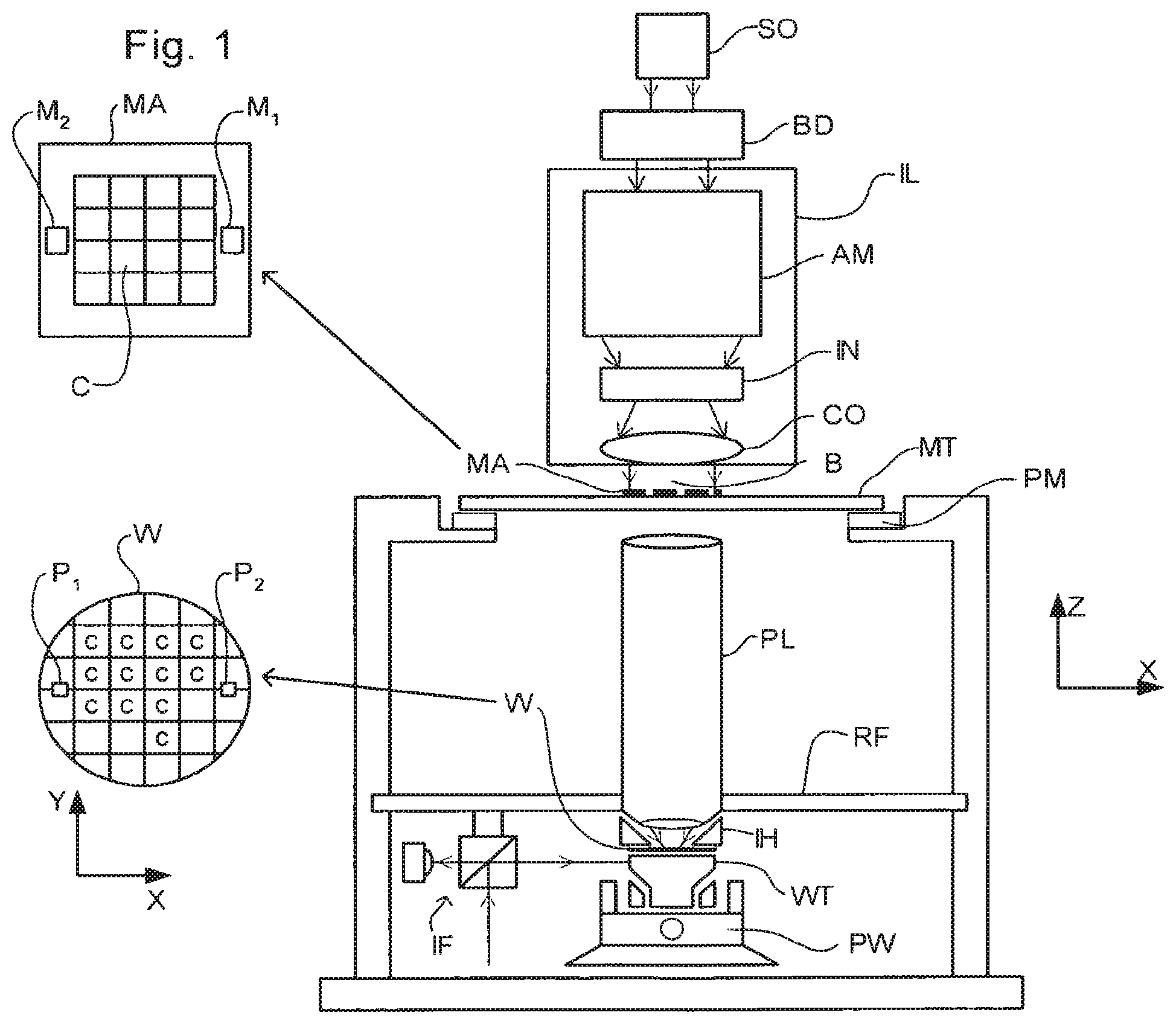
FIG. 1 depicts a lithographic apparatus according to an embodiment of the invention;
FIGS. 2 and 3 depict a liquid supply system for use in a lithographic projection apparatus;
FIG. 4 depicts a further liquid supply system for use in a lithographic projection apparatus;
FIG. 5 depicts a barrier member for use in an immersion lithographic apparatus;
FIG. 6 depicts an embodiment of the invention with a low level of immersion liquid;
FIG. 7 depicts the embodiment shown in FIG. 6 with a high level of immersion liquid;
FIG. 8 depicts a plan view of the embodiment depicted in FIGS. 6 and 7;
FIG. 9 depicts an embodiment of the invention;
FIG. 10 depicts another view of the embodiment depicted in FIG. 9; and
FIG. 11 depicts a plan view of the embodiment depicted in FIGS. 9 and 10;
FIG. 12 depicts an embodiment of the invention.
DETAILED DESCRIPTION
FIG. 1 schematically depicts a lithographic apparatus according to one embodiment of the invention. The apparatus comprises:
an illumination system (illuminator) IL configured to condition a radiation beam B (e.g. UV radiation or DUV radiation);
a support structure (e.g. a mask table) MT constructed to support a patterning device (e.g. a mask) MA and connected to a first positioner PM configured to accurately position the patterning device in accordance with certain parameters;
a substrate table (e.g. a wafer table) WT constructed to hold a substrate (e.g. a resist-coated wafer) W and connected to a second positioner PW configured to accurately position the substrate in accordance with certain parameters; and
a projection system (e.g. a refractive projection lens system) PL configured to project a pattern imparted to the radiation beam B by patterning device MA onto a target portion C (e.g. comprising one or more dies) of the substrate W.
The illumination system may include various types of optical components, such as refractive, reflective, magnetic, electromagnetic, electrostatic or other types of optical components, or any combination thereof, for directing, shaping, or controlling radiation.
The support structure holds the patterning device in a manner that depends on the orientation of the patterning device, the design of the lithographic apparatus, and other conditions, such as for example whether or not the patterning device is held in a vacuum environment. The support structure can use mechanical, vacuum, electrostatic or other clamping techniques to hold the patterning device. The support structure may be a frame or a table, for example, which may be fixed or movable as required. The support structure may ensure that the patterning device is at a desired position, for example with respect to the projection system. Any use of the terms "reticle" or "mask" herein may be considered synonymous with the more general term "patterning device."
The term "patterning device" used herein should be broadly interpreted as referring to any device that can be used to impart a radiation beam with a pattern in its cross-section such as to create a pattern in a target portion of the substrate. It should be noted that the pattern imparted to the radiation beam may not exactly correspond to the desired pattern in the target portion of the substrate, for example if the pattern includes phase-shifting features or so called assist features. Generally, the pattern imparted to the radiation beam will correspond to a particular functional layer in a device being created in the target portion, such as an integrated circuit.
The patterning device may be transmissive or reflective. Examples of patterning devices include masks, programmable mirror arrays, and programmable LCD panels. Masks are well known in lithography, and include mask types such as binary, alternating phase-shift, and attenuated phase-shift, as well as various hybrid mask types. An example of a programmable mirror array employs a matrix arrangement of small mirrors, each of which can be individually tilted so as to reflect an incoming radiation beam in different directions. The tilted mirrors impart a pattern in a radiation beam which is reflected by the mirror matrix.
The term "projection system" used herein should be broadly interpreted as encompassing any type of projection system, including refractive, reflective, catadioptric, magnetic, electromagnetic and electrostatic optical systems, or any combination thereof, as appropriate for the exposure radiation being used, or for other factors such as the use of an immersion liquid or the use of a vacuum. Any use of the term "projection lens" herein may be considered as synonymous with the more general term "projection system".
As here depicted, the apparatus is of a transmissive type (e.g. employing a transmissive mask). Alternatively, the apparatus may be of a reflective type (e.g. employing a programmable mirror array of a type as referred to above, or employing a reflective mask).
The lithographic apparatus may be of a type having two (dual stage) or more substrate tables (and/or two or more support structures). In such "multiple stage" machines the additional tables may be used in parallel, or preparatory steps may be carried out on one or more tables while one or more other tables are being used for exposure.
Referring to FIG. 1, the illuminator IL receives a radiation beam from a radiation source SO. The source and the lithographic apparatus may be separate entities, for example when the source is an excimer laser. In such cases, the source is not considered to form part of the lithographic apparatus and the radiation beam is passed from the source SO to the illuminator IL with the aid of a beam delivery system BD comprising, for example, suitable directing mirrors and/or a beam expander. In other cases the source may be an integral part of the lithographic apparatus, for example when the source is a mercury lamp. The source SO and the illuminator IL, together with the beam delivery system BD if required, may be referred to as a radiation system.
The illuminator IL may comprise an adjuster AM for adjusting the angular intensity distribution of the radiation beam. Generally, at least the outer and/or inner radial extent (commonly referred to as .sigma.-outer and .sigma.-inner, respectively) of the intensity distribution in a pupil plane of the illuminator can be adjusted. In addition, the illuminator IL may comprise various other components, such as an integrator IN and a condenser CO. The illuminator may be used to condition the radiation beam, to have a desired uniformity and intensity distribution in its cross-section.
The radiation beam B is incident on the patterning device (e.g., mask) MA, which is held on the support structure (e.g., mask table) MT, and is patterned by the patterning device. Having traversed the patterning device MA, the radiation beam B passes through the projection system PS, which focuses the beam onto a target portion C of the substrate W. With the aid of the second positioner PW and position sensor IF (e.g. an interferometric device, linear encoder or capacitive sensor), the substrate table WT can be moved accurately, e.g. so as to position different target portions C in the path of the radiation beam B. Similarly, the first positioner PM and another position sensor (which is not explicitly depicted in FIG. 1) can be used to accurately position the patterning device MA with respect to the path of the radiation beam B, e.g. after mechanical retrieval from a mask library, or during a scan. In general, movement of the support structure MT may be realized with the aid of a long-stroke module (coarse positioning) and a short-stroke module (fine positioning), which form part of the first positioner PM. Similarly, movement of the substrate table WT may be realized using a long-stroke module and a short-stroke module, which form part of the second positioner PW. In the case of a stepper (as opposed to a scanner) the support structure MT may be connected to a short-stroke actuator only, or may be fixed. Patterning device MA and substrate W may be aligned using patterning device alignment marks M1, M2 and substrate alignment marks P1, P2. Although the substrate alignment marks as illustrated occupy dedicated target portions, they may be located in spaces between target portions (these are known as scribe-lane alignment marks). Similarly, in situations in which more than one die is provided on the patterning device MA, the patterning device alignment marks may be located between the dies.
The depicted apparatus could be used in at least one of the following modes:
1. In step mode, the support structure MT and the substrate table WT are kept essentially stationary, while an entire pattern imparted to the radiation beam is projected onto a target portion C at one time (i.e. a single static exposure). The substrate table WT is then shifted in the X and/or Y direction so that a different target portion C can be exposed. In step mode, the maximum size of the exposure field limits the size of the target portion C imaged in a single static exposure.
2. In scan mode, the support structure MT and the substrate table WT are scanned synchronously while a pattern imparted to the radiation beam is projected onto a target portion C (i.e. a single dynamic exposure). The velocity and direction of the substrate table WT relative to the support structure MT may be determined by the (de-)magnification and image reversal characteristics of the projection system PS. In scan mode, the maximum size of the exposure field limits the width (in the non-scanning direction) of the target portion in a single dynamic exposure, whereas the length of the scanning motion determines the height (in the scanning direction) of the target portion.
3. In another mode, the support structure MT is kept essentially stationary holding a programmable patterning device, and the substrate table WT is moved or scanned while a pattern imparted to the radiation beam is projected onto a target portion C. In this mode, generally a pulsed radiation source is employed and the programmable patterning device is updated as required after each movement of the substrate table WT or in between successive radiation pulses during a scan. This mode of operation can be readily applied to maskless lithography that utilizes programmable patterning device, such as a programmable mirror array of a type as referred to above.
Combinations and/or variations on the above described modes of use or entirely different modes of use may also be employed.
As shown in FIG. 6 there are a plurality of conduits, 21, 22 arranged in the barrier member 12 around the projection system PL. Each of the conduits 21, 22 is arranged at a different position in the barrier member 12, in particular at a different level in the barrier member 12, and leads to a common chamber 25. As depicted in FIG. 6, conduit 21 is located above conduit 22. A passage 26 leads from the chamber 25. FIG. 6 shows a lithographic apparatus with a low level of immersion liquid. In this situation only the lower conduit 22 is in contact with the immersion liquid and is filled with immersion liquid whereas the upper conduit 21 is substantially free of immersion liquid. Suction is applied to the passage 26. As the conduit 21 is substantially free of immersion liquid mainly gas will be drawn through conduit 21 into the chamber 25 and through passage 26. Thus liquid flow through conduit 22 is substantially zero because there is substantially no pressure drop. In contrast, in the lithographic apparatus depicted in FIG. 7 the level of the immersion liquid is located above the level of the upper conduit 21. There is therefore a low pressure in chamber 25 and the suction applied to the passage 26 extracts immersion liquid from the apparatus through both conduits 21 and 22. When sufficient immersion liquid has been extracted to reduce the immersion liquid level below the level of the upper conduit 21 the liquid extraction capacity drops because there is substantially no pressure drop and gas begins to flow through the upper conduit 21. It should be noted that the suction applied to passage 26 is substantially constant but the liquid extraction capacity varies due to the contents of the conduits. When at least one of the conduits does not contain immersion liquid, the liquid extraction capacity will drop due to the suction of gas as there is only one conduit available to extract liquid. Thus when the level of the immersion liquid rises above the level of the upper conduit 21 the liquid extraction capacity increases until the excess immersion liquid is removed. It is therefore possible to vary the liquid extraction capacity of the apparatus according to the level of the immersion liquid to compensate for varying levels of the immersion liquid. In particular the level of the immersion liquid can be controlled in a passive manner. Advantageously a relatively large extraction flow may be achieved using this apparatus.
FIG. 8 shows a top plan view of the apparatus shown in FIGS. 6 and 7 wherein there are a plurality of liquid removal systems 25, 35, 45 provided adjacent to each other. Each liquid removal system has an upper conduit 21, 31, 41, a lower conduit 22, 32, 42, a chamber 25, 35, 45 and passages 26, 36, 46. The liquid removal systems are arranged around the projection system PL. The meniscus level may vary around the projection system and thus some upper conduits 21, 31, 41 may be submerged whereas others may comprise gas. Thus the level of the immersion liquid or meniscus position can be controlled around the entire projection system.
Although this embodiment shows only two conduits (e.g., 21, 22) in each liquid removal system there could be three, four or more arranged above each other and the suction capacity would depend on how many conduits are submerged.
As gas flows faster through the upper conduit 21 than immersion liquid through the lower conduit 22 the upper conduit 21 may have a smaller cross-section than the lower conduit 22. This will help reduce or minimize gas flow and thus vibration. Indeed the upper conduit 21 may have a cross sectional area 20 to 100 times smaller than the lower conduit 22.
FIGS. 9 to 11 depict an embodiment in which first and second conduits 121, 122 are arranged at different distances from the projection system PL. When the immersion liquid fills both conduits 121, 122 the extraction capacity is relatively high but when the immersion liquid fills only one, or indeed none of the extraction conduits the liquid extraction capacity is reduced. Thus when there is excess immersion liquid the liquid extraction capacity is higher than when there is less immersion liquid. As shown in FIG. 11, a plurality of liquid removal systems 25, 35, 45 may be provided arranged around the projection system PL. Each liquid removal system has a first conduit 121, 221, 321, a second conduit 122, 222, 322, a chamber 125, 225, 325 and passages.
Again conduits arranged further from the projection system PL can be narrower in diameter than those closer to the projection system PL.
As will be apparent, one or more features of one or more of the embodiments may be combined with or used alternatively with one or more features of one or more other of embodiments. For example, FIG. 12 shows features of the embodiment of FIG. 6 combined with features of the embodiment of FIG. 9.
In an embodiment, there is provided a lithographic apparatus, comprising: a projection system configured to project a patterned beam of radiation into an image field, the image field having a center; a substrate table constructed to position a target portion of a substrate in the image field; a barrier member configured to extend along at least part of a space between the projection system and the substrate, the barrier member comprising a liquid supply system constructed to supply the space with liquid; and a liquid extraction system, comprising: a passage configured to be subjected to an under pressure or suction flow, and a plurality of conduits connected between the passage and the space to remove liquid, the conduits arranged at different distances from the center of the image field.
In an embodiment, the plurality of conduits is arranged at different radial distances from the center of the image field. In an embodiment, a cross-sectional area of a conduit is less than a cross-sectional area of a conduit arranged radially closer to the center of the image field. In an embodiment, there is a plurality of liquid extraction systems arranged around the projection system. In an embodiment, each of the plurality of conduits and the passage is connected to a chamber. In an embodiment, the passage is located at substantially the same or further distance from the center of the image field of a conduit of the plurality of conduits.
In an embodiment, there is provided a device manufacturing method, comprising: projecting a projection beam of radiation using a projection system into an image field having a center; placing a target portion of a substrate in the image field; supplying liquid to a space between the projection system and the substrate; and providing suction to remove liquid from the space, the suction operating through a plurality of conduits, arranged at different distances from the center of the image field, connected to a passage.
In an embodiment, the plurality of conduits is arranged at different radial distances from the center of the image field. In an embodiment, a cross-sectional area of a conduit is less than a cross-sectional area of a conduit arranged radially closer to the center of the image field. In an embodiment, each of the plurality of conduits and the passage is connected to a chamber. In an embodiment, the passage is located at substantially the same or further distance from the center of the image field of a conduit of the plurality of conduits.
In an embodiment, there is provided a lithographic projection apparatus, comprising: a projection system configured to project a patterned beam of radiation into an image field; a substrate table constructed to position a target portion of a substrate in the image field; a barrier member configured to extend along at least part of a space between the projection system and the substrate, the barrier member comprising a liquid supply system constructed to supply the space with liquid; and a liquid extraction system, comprising: a passage configured to be subjected to an under pressure or suction flow; and a plurality of conduits connected between the passage and the space to remove liquid, the conduits arranged at different heights relative to the image field.
In an embodiment, a cross-sectional area of a conduit is less than a cross-sectional area of a conduit arranged below it in relation to the substrate table. In an embodiment, there is a plurality of liquid extraction systems arranged around the projection system. In an embodiment, each of the plurality of conduits and the passage is connected to a chamber. In an embodiment, the passage is located at substantially the same or further height relative to the image field of a conduit of the plurality of conduits.
In an embodiment, there is provided a device manufacturing method, comprising: projecting a projection beam of radiation onto a target portion of a substrate using a projection system; supplying liquid to a space between the projection system and the substrate; and providing suction to remove liquid, the suction operating through a plurality of conduits, arranged at different heights, connected to a passage.
In an embodiment, a cross-sectional area of a conduit is less than a cross-sectional area of a conduit arranged below it in relation to the substrate. In an embodiment, each of the plurality of conduits and the passage is connected to a chamber. In an embodiment, the passage is located at substantially the same or further height relative to the image field of a conduit of the plurality of conduits.
Although specific reference may be made in this text to the use of lithographic apparatus in the manufacture of ICs, it should be understood that the lithographic apparatus described herein may have other applications, such as the manufacture of integrated optical systems, guidance and detection patterns for magnetic domain memories, flat-panel displays, liquid-crystal displays (LCDs), thin-film magnetic heads, etc. The skilled artisan will appreciate that, in the context of such alternative applications, any use of the terms "wafer" or "die" herein may be considered as synonymous with the more general terms "substrate" or "target portion", respectively. The substrate referred to herein may be processed, before or after exposure, in for example a track (a tool that typically applies a layer of resist to a substrate and develops the exposed resist), a metrology tool and/or an inspection tool. Where applicable, the disclosure herein may be applied to such and other substrate processing tools. Further, the substrate may be processed more than once, for example in order to create a multi-layer IC, so that the term substrate used herein may also refer to a substrate that already contains multiple processed layers.
Although specific reference may have been made above to the use of embodiments of the invention in the context of optical lithography, it will be appreciated that the invention may be used in other applications, for example imprint lithography, and where the context allows, is not limited to optical lithography. In imprint lithography a topography in a patterning device defines the pattern created on a substrate. The topography of the patterning device may be pressed into a layer of resist supplied to the substrate whereupon the resist is cured by applying electromagnetic radiation, heat, pressure or a combination thereof. The patterning device is moved out of the resist leaving a pattern in it after the resist is cured.
The terms "radiation" and "beam" used herein encompass all types of electromagnetic radiation, including ultraviolet (UV) radiation (e.g. having a wavelength of or about 365, 248, 193, 157 or 126 nm) and extreme ultra-violet (EUV) radiation (e.g. having a wavelength in the range of 5-20 nm), as well as particle beams, such as ion beams or electron beams.
The term "lens", where the context allows, may refer to any one or combination of various types of optical components, including refractive, reflective, magnetic, electromagnetic and electrostatic optical components.
While specific embodiments of the invention have been described above, it will be appreciated that the invention may be practiced otherwise than as described. For example, the invention may take the form of a computer program containing one or more sequences of machine-readable instructions describing a method as disclosed above, or a data storage medium (e.g. semiconductor memory, magnetic or optical disk) having such a computer program stored therein.
One or more embodiments of the invention may be applied to any immersion lithography apparatus, in particular, but not exclusively, those types mentioned above and whether the immersion liquid is provided in the form of a bath or only on a localized surface area of the substrate. A liquid supply system as contemplated herein should be broadly construed. In certain embodiments, it may be a mechanism or combination of structures that provides a liquid to a space between the projection system and the substrate and/or substrate table. It may comprise a combination of one or more structures, one or more liquid inlets, one or more gas inlets, one or more gas outlets, and/or one or more liquid outlets that provide liquid to the space. In an embodiment, a surface of the space may be a portion of the substrate and/or substrate table, or a surface of the space may completely cover a surface of the substrate and/or substrate table, or the space may envelop the substrate and/or substrate table. The liquid supply system may optionally further include one or more elements to control the position, quantity, quality, shape, flow rate or any other features of the liquid.
The immersion liquid used in the apparatus may have different compositions, according to the desired properties and the wavelength of exposure radiation used. For an exposure wavelength of 193 nm, ultra pure water or water-based compositions may be used and for this reason the immersion liquid is sometimes referred to as water and water-related terms such as hydrophilic, hydrophobic, humidity, etc. may be used.
The descriptions above are intended to be illustrative, not limiting. Thus, it will be apparent to one skilled in the art that modifications may be made to the invention as described without departing from the scope of the claims set out below.
* * * * *
D00000
D00001
D00002
D00003
D00004
D00005
XML
uspto.report is an independent third-party trademark research tool that is not affiliated, endorsed, or sponsored by the United States Patent and Trademark Office (USPTO) or any other governmental organization. The information provided by uspto.report is based on publicly available data at the time of writing and is intended for informational purposes only.
While we strive to provide accurate and up-to-date information, we do not guarantee the accuracy, completeness, reliability, or suitability of the information displayed on this site. The use of this site is at your own risk. Any reliance you place on such information is therefore strictly at your own risk.
All official trademark data, including owner information, should be verified by visiting the official USPTO website at www.uspto.gov. This site is not intended to replace professional legal advice and should not be used as a substitute for consulting with a legal professional who is knowledgeable about trademark law.