Non-linear jaw gap for electrosurgical instruments
Worrell , et al.
U.S. patent number 10,646,269 [Application Number 15/142,425] was granted by the patent office on 2020-05-12 for non-linear jaw gap for electrosurgical instruments. This patent grant is currently assigned to Ethicon LLC. The grantee listed for this patent is Ethicon Endo-Surgery, LLC. Invention is credited to Gregory D. Bishop, Ellen M. Nienhaus, Barry C. Worrell.


| United States Patent | 10,646,269 |
| Worrell , et al. | May 12, 2020 |
Non-linear jaw gap for electrosurgical instruments
Abstract
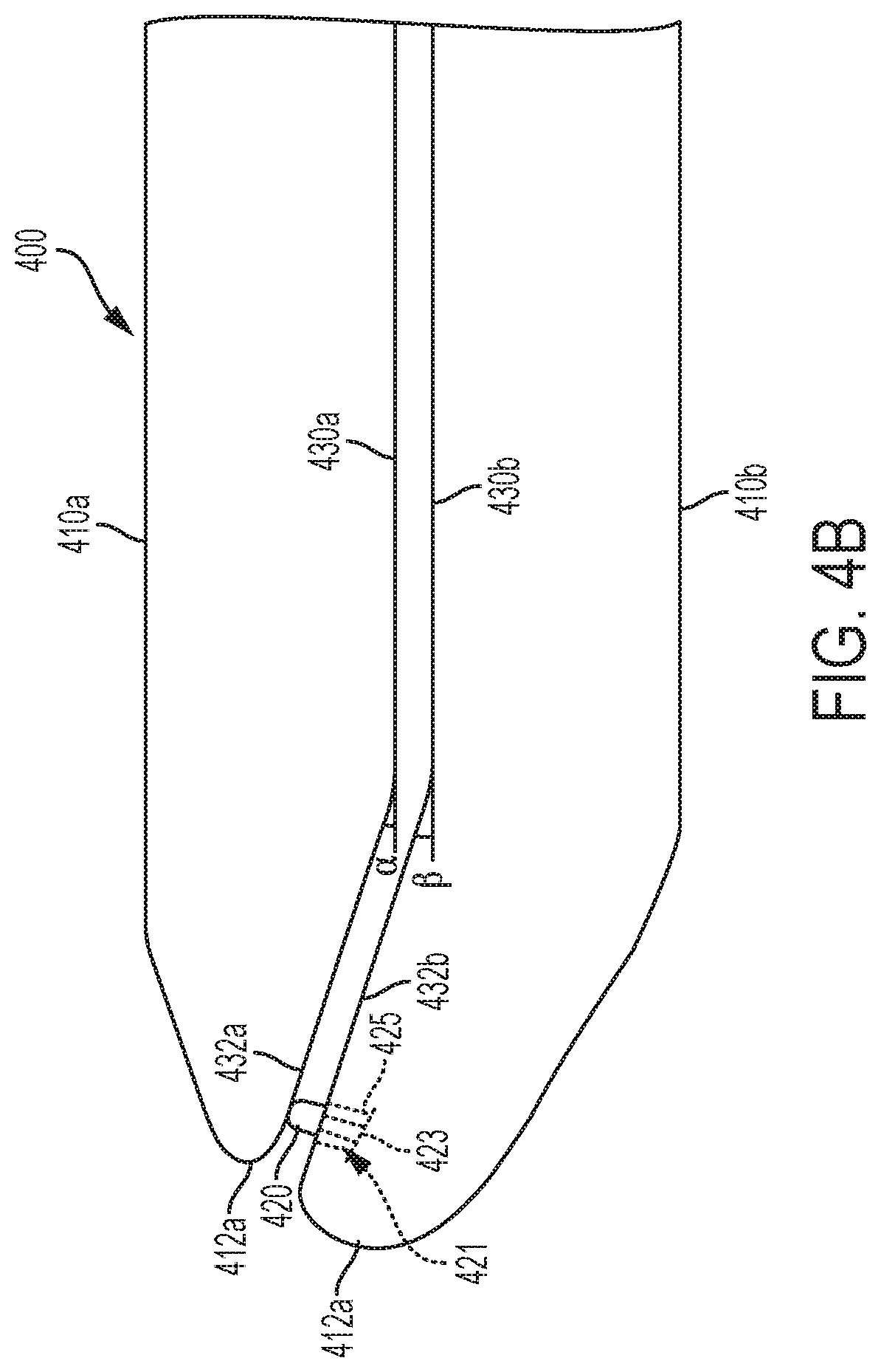
An end effector for an electrosurgical instrument is disclosed which comprises a first jaw comprising a first energy delivery surface, a first distal end, and a first proximal end; and a second jaw comprising a second energy delivery surface, a second distal end, and a second proximal end, wherein the first energy delivery surface comprises a first curved portion that is outwardly curved, and the second energy delivery surface comprises a second curved portion that is inwardly curved. The first jaw or the second jaw is configured for pivotal movement between an open position and a closed position. In the open position, the first and second distal ends are separated apart. In the closed position, the first and second distal ends are in proximity. The end effector also comprises an electrically conductive member which protrudes from either the first or second jaw.
| Inventors: | Worrell; Barry C. (Centerville, OH), Nienhaus; Ellen M. (Cincinnati, OH), Bishop; Gregory D. (Hamilton, OH) | ||||||||||
|---|---|---|---|---|---|---|---|---|---|---|---|
| Applicant: |
|
||||||||||
| Assignee: | Ethicon LLC (Guaynabo,
PR) |
||||||||||
| Family ID: | 58672724 | ||||||||||
| Appl. No.: | 15/142,425 | ||||||||||
| Filed: | April 29, 2016 |
Prior Publication Data
| Document Identifier | Publication Date | |
|---|---|---|
| US 20170312015 A1 | Nov 2, 2017 | |
| Current U.S. Class: | 1/1 |
| Current CPC Class: | A61B 18/1442 (20130101); A61B 18/1445 (20130101); A61B 2018/00053 (20130101); A61B 2017/00526 (20130101); A61B 2018/1455 (20130101); A61B 2018/00755 (20130101); A61B 18/1206 (20130101); A61B 2090/034 (20160201); A61B 2018/0063 (20130101); A61B 2018/126 (20130101) |
| Current International Class: | A61B 18/14 (20060101); A61B 18/12 (20060101); A61B 17/00 (20060101); A61B 18/00 (20060101); A61B 90/00 (20160101) |
References Cited [Referenced By]
U.S. Patent Documents
| 969528 | September 1910 | Disbrow |
| 1570025 | January 1926 | Young |
| 1813902 | July 1931 | Bovie |
| 2188497 | January 1940 | Calva |
| 2366274 | January 1945 | Luth et al. |
| 2425245 | August 1947 | Johnson |
| 2442966 | June 1948 | Wallace |
| 2458152 | January 1949 | Eakins |
| 2510693 | June 1950 | Green |
| 2597564 | May 1952 | Bugg |
| 2704333 | March 1955 | Calosi et al. |
| 2736960 | March 1956 | Armstrong |
| 2748967 | June 1956 | Roach |
| 2845072 | July 1958 | Shafer |
| 2849788 | September 1958 | Creek |
| 2867039 | January 1959 | Zach |
| 2874470 | February 1959 | Richards |
| 2990616 | July 1961 | Balamuth et al. |
| RE25033 | August 1961 | Balamuth et al. |
| 3015961 | January 1962 | Roney |
| 3033407 | May 1962 | Alfons |
| 3053124 | September 1962 | Balamuth et al. |
| 3082805 | March 1963 | Royce |
| 3166971 | January 1965 | Stoecker |
| 3322403 | May 1967 | Murphy |
| 3432691 | March 1969 | Shoh |
| 3433226 | March 1969 | Boyd |
| 3489930 | January 1970 | Shoh |
| 3513848 | May 1970 | Winston et al. |
| 3514856 | June 1970 | Camp et al. |
| 3525912 | August 1970 | Wallin |
| 3526219 | September 1970 | Balamuth |
| 3554198 | January 1971 | Tatoian et al. |
| 3580841 | May 1971 | Cadotte et al. |
| 3606682 | September 1971 | Camp et al. |
| 3614484 | October 1971 | Shoh |
| 3616375 | October 1971 | Inoue |
| 3629726 | December 1971 | Popescu |
| 3636943 | January 1972 | Balamuth |
| 3668486 | June 1972 | Silver |
| 3702948 | November 1972 | Balamuth |
| 3703651 | November 1972 | Blowers |
| 3776238 | December 1973 | Peyman et al. |
| 3777760 | December 1973 | Essner |
| 3805787 | April 1974 | Banko |
| 3809977 | May 1974 | Balamuth et al. |
| 3830098 | August 1974 | Antonevich |
| 3854737 | December 1974 | Gilliam, Sr. |
| 3862630 | January 1975 | Balamuth |
| 3875945 | April 1975 | Friedman |
| 3885438 | May 1975 | Harris, Sr. et al. |
| 3900823 | August 1975 | Sokal et al. |
| 3918442 | November 1975 | Nikolaev et al. |
| 3924335 | December 1975 | Balamuth et al. |
| 3946738 | March 1976 | Newton et al. |
| 3955859 | May 1976 | Stella et al. |
| 3956826 | May 1976 | Perdreaux, Jr. |
| 3989952 | November 1976 | Hohmann |
| 4005714 | February 1977 | Hiltebrandt |
| 4012647 | March 1977 | Balamuth et al. |
| 4034762 | July 1977 | Cosens et al. |
| 4058126 | November 1977 | Leveen |
| 4074719 | February 1978 | Semm |
| 4156187 | May 1979 | Murry et al. |
| 4167944 | September 1979 | Banko |
| 4188927 | February 1980 | Harris |
| 4200106 | April 1980 | Douvas et al. |
| 4203430 | May 1980 | Takahashi |
| 4203444 | May 1980 | Bonnell et al. |
| 4220154 | September 1980 | Semm |
| 4237441 | December 1980 | van Konynenburg et al. |
| 4244371 | January 1981 | Farin |
| 4281785 | August 1981 | Brooks |
| 4300083 | November 1981 | Heiges |
| 4302728 | November 1981 | Nakamura |
| 4304987 | December 1981 | van Konynenburg |
| 4306570 | December 1981 | Matthews |
| 4314559 | February 1982 | Allen |
| 4353371 | October 1982 | Cosman |
| 4409981 | October 1983 | Lundberg |
| 4445063 | April 1984 | Smith |
| 4463759 | August 1984 | Garito et al. |
| 4491132 | January 1985 | Aikins |
| 4492231 | January 1985 | Auth |
| 4494759 | January 1985 | Kieffer |
| 4504264 | March 1985 | Kelman |
| 4512344 | April 1985 | Barber |
| 4526571 | July 1985 | Wuchinich |
| 4535773 | August 1985 | Yoon |
| 4541638 | September 1985 | Ogawa et al. |
| 4545374 | October 1985 | Jacobson |
| 4545926 | October 1985 | Fouts, Jr. et al. |
| 4549147 | October 1985 | Kondo |
| 4550870 | November 1985 | Krumme et al. |
| 4553544 | November 1985 | Nomoto et al. |
| 4562838 | January 1986 | Walker |
| 4574615 | March 1986 | Bower et al. |
| 4582236 | April 1986 | Hirose |
| 4593691 | June 1986 | Lindstrom et al. |
| 4617927 | October 1986 | Manes |
| 4633119 | December 1986 | Thompson |
| 4633874 | January 1987 | Chow et al. |
| 4634420 | January 1987 | Spinosa et al. |
| 4640279 | February 1987 | Beard |
| 4641053 | February 1987 | Takeda |
| 4646738 | March 1987 | Trott |
| 4646756 | March 1987 | Watmough et al. |
| 4649919 | March 1987 | Thimsen et al. |
| 4662068 | May 1987 | Polonsky |
| 4674502 | June 1987 | Imonti |
| 4694835 | September 1987 | Strand |
| 4708127 | November 1987 | Abdelghani |
| 4712722 | December 1987 | Hood et al. |
| 4735603 | April 1988 | Goodson et al. |
| 4761871 | August 1988 | O'Connor et al. |
| 4808154 | February 1989 | Freeman |
| 4819635 | April 1989 | Shapiro |
| 4827911 | May 1989 | Broadwin et al. |
| 4830462 | May 1989 | Karny et al. |
| 4832683 | May 1989 | Idemoto et al. |
| 4836186 | June 1989 | Scholz |
| 4838853 | June 1989 | Parisi |
| 4844064 | July 1989 | Thimsen et al. |
| 4849133 | July 1989 | Yoshida et al. |
| 4850354 | July 1989 | McGurk-Burleson et al. |
| 4852578 | August 1989 | Companion et al. |
| 4860745 | August 1989 | Farin et al. |
| 4862890 | September 1989 | Stasz et al. |
| 4865159 | September 1989 | Jamison |
| 4867157 | September 1989 | McGurk-Burleson et al. |
| 4878493 | November 1989 | Pasternak et al. |
| 4880015 | November 1989 | Nierman |
| 4881550 | November 1989 | Kothe |
| 4896009 | January 1990 | Pawlowski |
| 4903696 | February 1990 | Stasz et al. |
| 4910389 | March 1990 | Sherman et al. |
| 4915643 | April 1990 | Samejima et al. |
| 4920978 | May 1990 | Colvin |
| 4922902 | May 1990 | Wuchinich et al. |
| 4936842 | June 1990 | D'Amelio et al. |
| 4954960 | September 1990 | Lo et al. |
| 4965532 | October 1990 | Sakurai |
| 4979952 | December 1990 | Kubota et al. |
| 4981756 | January 1991 | Rhandhawa |
| 5001649 | March 1991 | Lo et al. |
| 5009661 | April 1991 | Michelson |
| 5013956 | May 1991 | Kurozumi et al. |
| 5015227 | May 1991 | Broadwin et al. |
| 5020514 | June 1991 | Heckele |
| 5026370 | June 1991 | Lottick |
| 5026387 | June 1991 | Thomas |
| 5035695 | July 1991 | Weber, Jr. et al. |
| 5042461 | August 1991 | Inoue et al. |
| 5042707 | August 1991 | Taheri |
| 5061269 | October 1991 | Muller |
| 5075839 | December 1991 | Fisher et al. |
| 5084052 | January 1992 | Jacobs |
| 5099840 | March 1992 | Goble et al. |
| 5104025 | April 1992 | Main et al. |
| 5105117 | April 1992 | Yamaguchi |
| 5106538 | April 1992 | Barma et al. |
| 5108383 | April 1992 | White |
| 5109819 | May 1992 | Custer et al. |
| 5112300 | May 1992 | Ureche |
| 5113139 | May 1992 | Furukawa |
| 5123903 | June 1992 | Quaid et al. |
| 5126618 | June 1992 | Takahashi et al. |
| D327872 | July 1992 | McMills et al. |
| 5152762 | October 1992 | McElhenney |
| 5156633 | October 1992 | Smith |
| 5160334 | November 1992 | Billings et al. |
| 5162044 | November 1992 | Gahn et al. |
| 5163421 | November 1992 | Bernstein et al. |
| 5163537 | November 1992 | Radev |
| 5163945 | November 1992 | Ortiz et al. |
| 5167619 | December 1992 | Wuchinich |
| 5167725 | December 1992 | Clark et al. |
| 5172344 | December 1992 | Ehrlich |
| 5174276 | December 1992 | Crockard |
| D332660 | January 1993 | Rawson et al. |
| 5176677 | January 1993 | Wuchinich |
| 5176695 | January 1993 | Dulebohn |
| 5184605 | February 1993 | Grzeszykowski |
| 5188102 | February 1993 | Idemoto et al. |
| D334173 | March 1993 | Liu et al. |
| 5190517 | March 1993 | Zieve et al. |
| 5190518 | March 1993 | Takasu |
| 5190541 | March 1993 | Abele et al. |
| 5196007 | March 1993 | Ellman et al. |
| 5205459 | April 1993 | Brinkerhoff et al. |
| 5205817 | April 1993 | Idemoto et al. |
| 5209719 | May 1993 | Baruch et al. |
| 5213569 | May 1993 | Davis |
| 5214339 | May 1993 | Naito |
| 5217460 | June 1993 | Knoepfler |
| 5218529 | June 1993 | Meyer et al. |
| 5221282 | June 1993 | Wuchinich |
| 5222937 | June 1993 | Kagawa |
| 5226909 | July 1993 | Evans et al. |
| 5226910 | July 1993 | Kajiyama et al. |
| 5231989 | August 1993 | Middleman et al. |
| 5234428 | August 1993 | Kaufman |
| 5241236 | August 1993 | Sasaki et al. |
| 5241968 | September 1993 | Slater |
| 5242339 | September 1993 | Thornton |
| 5242460 | September 1993 | Klein et al. |
| 5246003 | September 1993 | DeLonzor |
| 5254129 | October 1993 | Alexander |
| 5257988 | November 1993 | L'Esperance, Jr. |
| 5258004 | November 1993 | Bales et al. |
| 5258006 | November 1993 | Rydell et al. |
| 5261922 | November 1993 | Hood |
| 5263957 | November 1993 | Davison |
| 5264925 | November 1993 | Shipp et al. |
| 5269297 | December 1993 | Weng et al. |
| 5275166 | January 1994 | Vaitekunas et al. |
| 5275607 | January 1994 | Lo et al. |
| 5275609 | January 1994 | Pingleton et al. |
| 5282800 | February 1994 | Foshee et al. |
| 5282817 | February 1994 | Hoogeboom et al. |
| 5285795 | February 1994 | Ryan et al. |
| 5285945 | February 1994 | Brinkerhoff et al. |
| 5290286 | March 1994 | Parins |
| 5293863 | March 1994 | Zhu et al. |
| 5300068 | April 1994 | Rosar et al. |
| 5304115 | April 1994 | Pflueger et al. |
| D347474 | May 1994 | Olson |
| 5307976 | May 1994 | Olson et al. |
| 5309927 | May 1994 | Welch |
| 5312023 | May 1994 | Green et al. |
| 5312425 | May 1994 | Evans et al. |
| 5318525 | June 1994 | West et al. |
| 5318563 | June 1994 | Malis et al. |
| 5318564 | June 1994 | Eggers |
| 5318570 | June 1994 | Hood et al. |
| 5318589 | June 1994 | Lichtman |
| 5322055 | June 1994 | Davison et al. |
| 5324299 | June 1994 | Davison et al. |
| 5326013 | July 1994 | Green et al. |
| 5326342 | July 1994 | Pflueger et al. |
| 5330471 | July 1994 | Eggers |
| 5330502 | July 1994 | Hassler et al. |
| 5334183 | August 1994 | Wuchinich |
| 5339723 | August 1994 | Huitema |
| 5342356 | August 1994 | Ellman et al. |
| 5342359 | August 1994 | Rydell |
| 5344420 | September 1994 | Hilal et al. |
| 5345937 | September 1994 | Middleman et al. |
| 5346502 | September 1994 | Estabrook et al. |
| 5353474 | October 1994 | Good et al. |
| 5357164 | October 1994 | Imabayashi et al. |
| 5357423 | October 1994 | Weaver et al. |
| 5359994 | November 1994 | Krauter et al. |
| 5361583 | November 1994 | Huitema |
| 5366466 | November 1994 | Christian et al. |
| 5368557 | November 1994 | Nita et al. |
| 5370645 | December 1994 | Klicek et al. |
| 5371429 | December 1994 | Manna |
| 5374813 | December 1994 | Shipp |
| D354564 | January 1995 | Medema |
| 5381067 | January 1995 | Greenstein et al. |
| 5383874 | January 1995 | Jackson et al. |
| 5387207 | February 1995 | Dyer et al. |
| 5387215 | February 1995 | Fisher |
| 5389098 | February 1995 | Tsuruta et al. |
| 5394187 | February 1995 | Shipp |
| 5395033 | March 1995 | Byrne et al. |
| 5395312 | March 1995 | Desai |
| 5395363 | March 1995 | Billings et al. |
| 5395364 | March 1995 | Anderhub et al. |
| 5396266 | March 1995 | Brimhall |
| 5396900 | March 1995 | Slater et al. |
| 5400267 | March 1995 | Denen et al. |
| 5403312 | April 1995 | Yates et al. |
| 5403334 | April 1995 | Evans et al. |
| 5406503 | April 1995 | Williams, Jr. et al. |
| 5408268 | April 1995 | Shipp |
| D358887 | May 1995 | Feinberg |
| 5411481 | May 1995 | Allen et al. |
| 5417709 | May 1995 | Slater |
| 5419761 | May 1995 | Narayanan et al. |
| 5421829 | June 1995 | Olichney et al. |
| 5423844 | June 1995 | Miller |
| 5428504 | June 1995 | Bhatla |
| 5429131 | July 1995 | Scheinman et al. |
| 5438997 | August 1995 | Sieben et al. |
| 5441499 | August 1995 | Fritzsch |
| 5443463 | August 1995 | Stern et al. |
| 5445638 | August 1995 | Rydell et al. |
| 5445639 | August 1995 | Kuslich et al. |
| 5447509 | September 1995 | Mills et al. |
| 5449370 | September 1995 | Vaitekunas |
| 5451053 | September 1995 | Garrido |
| 5451161 | September 1995 | Sharp |
| 5451220 | September 1995 | Ciervo |
| 5451227 | September 1995 | Michaelson |
| 5456684 | October 1995 | Schmidt et al. |
| 5458598 | October 1995 | Feinberg et al. |
| 5462604 | October 1995 | Shibano et al. |
| 5465895 | November 1995 | Knodel et al. |
| 5471988 | December 1995 | Fujio et al. |
| 5472443 | December 1995 | Cordis et al. |
| 5476479 | December 1995 | Green et al. |
| 5478003 | December 1995 | Green et al. |
| 5480409 | January 1996 | Riza |
| 5483501 | January 1996 | Park et al. |
| 5484436 | January 1996 | Eggers et al. |
| 5486162 | January 1996 | Brumbach |
| 5486189 | January 1996 | Mudry et al. |
| 5490860 | February 1996 | Middle et al. |
| 5496317 | March 1996 | Goble et al. |
| 5499992 | March 1996 | Meade et al. |
| 5500216 | March 1996 | Julian et al. |
| 5501654 | March 1996 | Failla et al. |
| 5504650 | April 1996 | Katsui et al. |
| 5505693 | April 1996 | Mackool |
| 5507297 | April 1996 | Slater et al. |
| 5507738 | April 1996 | Ciervo |
| 5509922 | April 1996 | Aranyi et al. |
| 5511556 | April 1996 | DeSantis |
| 5520704 | May 1996 | Castro et al. |
| 5522832 | June 1996 | Kugo et al. |
| 5522839 | June 1996 | Pilling |
| 5527331 | June 1996 | Kresch et al. |
| 5531744 | July 1996 | Nardella et al. |
| 5540681 | July 1996 | Strul et al. |
| 5540693 | July 1996 | Fisher |
| 5542916 | August 1996 | Hirsch et al. |
| 5548286 | August 1996 | Craven |
| 5549637 | August 1996 | Crainich |
| 5553675 | September 1996 | Pitzen et al. |
| 5558671 | September 1996 | Yates |
| 5562609 | October 1996 | Brumbach |
| 5562610 | October 1996 | Brumbach |
| 5562659 | October 1996 | Morris |
| 5562703 | October 1996 | Desai |
| 5563179 | October 1996 | Stone et al. |
| 5569164 | October 1996 | Lurz |
| 5571121 | November 1996 | Heifetz |
| 5573424 | November 1996 | Poppe |
| 5573533 | November 1996 | Strul |
| 5573534 | November 1996 | Stone |
| 5577654 | November 1996 | Bishop |
| 5584830 | December 1996 | Ladd et al. |
| 5591187 | January 1997 | Dekel |
| 5593414 | January 1997 | Shipp et al. |
| 5599350 | February 1997 | Schulze et al. |
| 5600526 | February 1997 | Russell et al. |
| 5601601 | February 1997 | Tal et al. |
| 5603773 | February 1997 | Campbell |
| 5607436 | March 1997 | Pratt et al. |
| 5607450 | March 1997 | Zvenyatsky et al. |
| 5609573 | March 1997 | Sandock |
| 5611813 | March 1997 | Lichtman |
| 5618304 | April 1997 | Hart et al. |
| 5618307 | April 1997 | Donlon et al. |
| 5618492 | April 1997 | Auten et al. |
| 5620447 | April 1997 | Smith et al. |
| 5624452 | April 1997 | Yates |
| 5626587 | May 1997 | Bishop et al. |
| 5626595 | May 1997 | Sklar et al. |
| 5628760 | May 1997 | Knoepfler |
| 5630420 | May 1997 | Vaitekunas |
| 5632432 | May 1997 | Schulze |
| 5632717 | May 1997 | Yoon |
| 5640741 | June 1997 | Yano |
| D381077 | July 1997 | Hunt |
| 5647871 | July 1997 | Levine et al. |
| 5649937 | July 1997 | Bito et al. |
| 5649955 | July 1997 | Hashimoto et al. |
| 5651780 | July 1997 | Jackson et al. |
| 5653713 | August 1997 | Michelson |
| 5655100 | August 1997 | Ebrahim et al. |
| 5658281 | August 1997 | Heard |
| 5662662 | September 1997 | Bishop et al. |
| 5662667 | September 1997 | Knodel |
| 5665085 | September 1997 | Nardella |
| 5665100 | September 1997 | Yoon |
| 5669922 | September 1997 | Hood |
| 5674219 | October 1997 | Monson et al. |
| 5674220 | October 1997 | Fox et al. |
| 5674235 | October 1997 | Parisi |
| 5678568 | October 1997 | Uchikubo et al. |
| 5688270 | November 1997 | Yates |
| 5690269 | November 1997 | Bolanos et al. |
| 5693051 | December 1997 | Schulze et al. |
| 5694936 | December 1997 | Fujimoto et al. |
| 5695510 | December 1997 | Hood |
| 5700261 | December 1997 | Brinkerhoff |
| 5704534 | January 1998 | Huitema et al. |
| 5704791 | January 1998 | Gillio |
| 5707369 | January 1998 | Vaitekunas et al. |
| 5709680 | January 1998 | Yates et al. |
| 5711472 | January 1998 | Bryan |
| 5713896 | February 1998 | Nardella |
| 5715817 | February 1998 | Stevens-Wright et al. |
| 5716366 | February 1998 | Yates |
| 5717306 | February 1998 | Shipp |
| 5720742 | February 1998 | Zacharias |
| 5720744 | February 1998 | Eggleston et al. |
| 5722980 | March 1998 | Schulz et al. |
| 5723970 | March 1998 | Bell |
| 5728130 | March 1998 | Ishikawa et al. |
| 5730752 | March 1998 | Alden et al. |
| 5733074 | March 1998 | Stock et al. |
| 5735848 | April 1998 | Yates et al. |
| 5741226 | April 1998 | Strukel et al. |
| 5743906 | April 1998 | Parins et al. |
| 5752973 | May 1998 | Kieturakis |
| 5755717 | May 1998 | Yates et al. |
| 5762255 | June 1998 | Chrisman et al. |
| 5766164 | June 1998 | Mueller et al. |
| 5772659 | June 1998 | Becker et al. |
| 5776130 | July 1998 | Buysse et al. |
| 5776155 | July 1998 | Beaupre et al. |
| 5779130 | July 1998 | Alesi et al. |
| 5779701 | July 1998 | McBrayer et al. |
| 5782834 | July 1998 | Lucey et al. |
| 5792135 | August 1998 | Madhani et al. |
| 5792138 | August 1998 | Shipp |
| 5792165 | August 1998 | Klieman et al. |
| 5796188 | August 1998 | Bays |
| 5797941 | August 1998 | Schulze et al. |
| 5797958 | August 1998 | Yoon |
| 5797959 | August 1998 | Castro et al. |
| 5800432 | September 1998 | Swanson |
| 5800448 | September 1998 | Banko |
| 5800449 | September 1998 | Wales |
| 5805140 | September 1998 | Rosenberg et al. |
| 5807393 | September 1998 | Williamson, IV et al. |
| 5808396 | September 1998 | Boukhny |
| 5810811 | September 1998 | Yates et al. |
| 5810828 | September 1998 | Lightman et al. |
| 5810859 | September 1998 | DiMatteo et al. |
| 5817033 | October 1998 | DeSantis et al. |
| 5817084 | October 1998 | Jensen |
| 5817093 | October 1998 | Williamson, IV et al. |
| 5817119 | October 1998 | Klieman et al. |
| 5823197 | October 1998 | Edwards |
| 5827271 | October 1998 | Buysse et al. |
| 5827323 | October 1998 | Klieman et al. |
| 5828160 | October 1998 | Sugishita |
| 5833696 | November 1998 | Whitfield et al. |
| 5836897 | November 1998 | Sakurai et al. |
| 5836909 | November 1998 | Cosmescu |
| 5836943 | November 1998 | Miller, III |
| 5836957 | November 1998 | Schulz et al. |
| 5836990 | November 1998 | Li |
| 5843109 | December 1998 | Mehta et al. |
| 5851212 | December 1998 | Zirps et al. |
| 5853412 | December 1998 | Mayenberger |
| 5854590 | December 1998 | Dalstein |
| 5858018 | January 1999 | Shipp et al. |
| 5865361 | February 1999 | Milliman et al. |
| 5873873 | February 1999 | Smith et al. |
| 5873882 | February 1999 | Straub et al. |
| 5876401 | March 1999 | Schulze et al. |
| 5878193 | March 1999 | Wang et al. |
| 5879364 | March 1999 | Bromfield et al. |
| 5880668 | March 1999 | Hall |
| 5883615 | March 1999 | Fago et al. |
| 5891142 | April 1999 | Eggers et al. |
| 5893835 | April 1999 | Witt et al. |
| 5897523 | April 1999 | Wright et al. |
| 5897569 | April 1999 | Kellogg et al. |
| 5903607 | May 1999 | Tailliet |
| 5904681 | May 1999 | West, Jr. |
| 5906625 | May 1999 | Bito |
| 5906627 | May 1999 | Spaulding |
| 5906628 | May 1999 | Miyawaki et al. |
| 5910129 | June 1999 | Koblish et al. |
| 5911699 | June 1999 | Anis et al. |
| 5913823 | June 1999 | Hedberg et al. |
| 5916229 | June 1999 | Evans |
| 5921956 | July 1999 | Grinberg et al. |
| 5929846 | July 1999 | Rosenberg et al. |
| 5935143 | August 1999 | Hood |
| 5935144 | August 1999 | Estabrook |
| 5938633 | August 1999 | Beaupre |
| 5944718 | August 1999 | Austin et al. |
| 5944737 | August 1999 | Tsonton et al. |
| 5947984 | September 1999 | Whipple |
| 5954717 | September 1999 | Behl et al. |
| 5954736 | September 1999 | Bishop et al. |
| 5954746 | September 1999 | Holthaus et al. |
| 5957882 | September 1999 | Nita et al. |
| 5957943 | September 1999 | Vaitekunas |
| 5968007 | October 1999 | Simon et al. |
| 5968060 | October 1999 | Kellogg |
| 5974342 | October 1999 | Petrofsky |
| D416089 | November 1999 | Barton et al. |
| 5980510 | November 1999 | Tsonton et al. |
| 5980546 | November 1999 | Hood |
| 5984938 | November 1999 | Yoon |
| 5989274 | November 1999 | Davison et al. |
| 5989275 | November 1999 | Estabrook et al. |
| 5993465 | November 1999 | Shipp et al. |
| 5993972 | November 1999 | Reich et al. |
| 5994855 | November 1999 | Lundell et al. |
| 6003517 | December 1999 | Sheffield et al. |
| 6004335 | December 1999 | Vaitekunas et al. |
| 6013052 | January 2000 | Durman et al. |
| 6024741 | February 2000 | Williamson, IV et al. |
| 6024744 | February 2000 | Kese et al. |
| 6024750 | February 2000 | Mastri et al. |
| 6027515 | February 2000 | Cimino |
| 6031526 | February 2000 | Shipp |
| 6033375 | March 2000 | Brumbach |
| 6033399 | March 2000 | Gines |
| 6036667 | March 2000 | Manna et al. |
| 6036707 | March 2000 | Spaulding |
| 6039734 | March 2000 | Goble |
| 6048224 | April 2000 | Kay |
| 6050943 | April 2000 | Slayton et al. |
| 6050996 | April 2000 | Schmaltz et al. |
| 6051010 | April 2000 | DiMatteo et al. |
| 6056735 | May 2000 | Okada et al. |
| 6063098 | May 2000 | Houser et al. |
| 6066132 | May 2000 | Chen et al. |
| 6066151 | May 2000 | Miyawaki et al. |
| 6068627 | May 2000 | Orszulak et al. |
| 6068629 | May 2000 | Haissaguerre et al. |
| 6068647 | May 2000 | Witt et al. |
| 6074389 | June 2000 | Levine et al. |
| 6077285 | June 2000 | Boukhny |
| 6080149 | June 2000 | Huang et al. |
| 6083191 | July 2000 | Rose |
| 6086584 | July 2000 | Miller |
| 6090120 | July 2000 | Wright et al. |
| 6091995 | July 2000 | Ingle et al. |
| 6096033 | August 2000 | Tu et al. |
| 6099483 | August 2000 | Palmer et al. |
| 6099542 | August 2000 | Cohn et al. |
| 6099550 | August 2000 | Yoon |
| 6109500 | August 2000 | Alli et al. |
| 6110127 | August 2000 | Suzuki |
| 6113594 | September 2000 | Savage |
| 6113598 | September 2000 | Baker |
| 6117152 | September 2000 | Huitema |
| H001904 | October 2000 | Yates et al. |
| 6126629 | October 2000 | Perkins |
| 6126658 | October 2000 | Baker |
| 6129735 | October 2000 | Okada et al. |
| 6129740 | October 2000 | Michelson |
| 6132368 | October 2000 | Cooper |
| 6132427 | October 2000 | Jones et al. |
| 6132429 | October 2000 | Baker |
| 6132448 | October 2000 | Perez et al. |
| 6139320 | October 2000 | Hahn |
| 6139561 | October 2000 | Shibata et al. |
| 6142615 | November 2000 | Qiu et al. |
| 6142994 | November 2000 | Swanson et al. |
| 6144402 | November 2000 | Norsworthy et al. |
| 6147560 | November 2000 | Erhage et al. |
| 6152902 | November 2000 | Christian et al. |
| 6152923 | November 2000 | Ryan |
| 6154198 | November 2000 | Rosenberg |
| 6156029 | December 2000 | Mueller |
| 6159160 | December 2000 | Hsei et al. |
| 6159175 | December 2000 | Strukel et al. |
| 6162194 | December 2000 | Shipp |
| 6162208 | December 2000 | Hipps |
| 6165150 | December 2000 | Banko |
| 6174309 | January 2001 | Wrublewski et al. |
| 6174310 | January 2001 | Kirwan, Jr. |
| 6176857 | January 2001 | Ashley |
| 6179853 | January 2001 | Sachse et al. |
| 6183426 | February 2001 | Akisada et al. |
| 6187003 | February 2001 | Buysse |
| 6190386 | February 2001 | Rydell |
| 6193709 | February 2001 | Miyawaki et al. |
| 6204592 | March 2001 | Hur |
| 6205383 | March 2001 | Hermann |
| 6205855 | March 2001 | Pfeiffer |
| 6206844 | March 2001 | Reichel et al. |
| 6206876 | March 2001 | Levine et al. |
| 6210337 | April 2001 | Dunham et al. |
| 6210402 | April 2001 | Olsen et al. |
| 6210403 | April 2001 | Klicek |
| 6214023 | April 2001 | Whipple et al. |
| 6228080 | May 2001 | Gines |
| 6231565 | May 2001 | Tovey et al. |
| 6232899 | May 2001 | Craven |
| 6233476 | May 2001 | Strommer et al. |
| 6238366 | May 2001 | Savage et al. |
| 6241724 | June 2001 | Fleischman et al. |
| 6245065 | June 2001 | Panescu et al. |
| 6251110 | June 2001 | Wampler |
| 6252110 | June 2001 | Uemura et al. |
| D444365 | July 2001 | Bass et al. |
| D445092 | July 2001 | Lee |
| D445764 | July 2001 | Lee |
| 6254623 | July 2001 | Haibel, Jr. et al. |
| 6257241 | July 2001 | Wampler |
| 6258034 | July 2001 | Hanafy |
| 6259230 | July 2001 | Chou |
| 6267761 | July 2001 | Ryan |
| 6270831 | August 2001 | Kumar et al. |
| 6273852 | August 2001 | Lehe et al. |
| 6274963 | August 2001 | Estabrook et al. |
| 6277115 | August 2001 | Saadat |
| 6277117 | August 2001 | Tetzlaff et al. |
| 6278218 | August 2001 | Madan et al. |
| 6280407 | August 2001 | Manna et al. |
| 6283981 | September 2001 | Beaupre |
| 6287344 | September 2001 | Wampler et al. |
| 6290575 | September 2001 | Shipp |
| 6292700 | September 2001 | Morrison et al. |
| 6299591 | October 2001 | Banko |
| 6306131 | October 2001 | Hareyama et al. |
| 6306157 | October 2001 | Shchervinsky |
| 6309400 | October 2001 | Beaupre |
| 6311783 | November 2001 | Harpell |
| 6319221 | November 2001 | Savage et al. |
| 6325795 | December 2001 | Lindemann et al. |
| 6325799 | December 2001 | Goble |
| 6325811 | December 2001 | Messerly |
| 6328751 | December 2001 | Beaupre |
| 6332891 | December 2001 | Himes |
| 6338657 | January 2002 | Harper et al. |
| 6340352 | January 2002 | Okada et al. |
| 6340878 | January 2002 | Oglesbee |
| 6350269 | February 2002 | Shipp et al. |
| 6352532 | March 2002 | Kramer et al. |
| 6356224 | March 2002 | Wohlfarth |
| 6358246 | March 2002 | Behl et al. |
| 6358264 | March 2002 | Banko |
| 6364888 | April 2002 | Niemeyer et al. |
| 6379320 | April 2002 | Lafon et al. |
| D457958 | May 2002 | Dycus et al. |
| 6383194 | May 2002 | Pothula |
| 6384690 | May 2002 | Wilhelmsson et al. |
| 6387094 | May 2002 | Eitenmuller |
| 6387109 | May 2002 | Davison et al. |
| 6388657 | May 2002 | Natoli |
| 6390973 | May 2002 | Ouchi |
| 6391026 | May 2002 | Hung et al. |
| 6391042 | May 2002 | Cimino |
| 6398779 | June 2002 | Buysse et al. |
| 6402743 | June 2002 | Orszulak et al. |
| 6402748 | June 2002 | Schoenman et al. |
| 6405184 | June 2002 | Bohme et al. |
| 6405733 | June 2002 | Fogarty et al. |
| 6409722 | June 2002 | Hoey et al. |
| H002037 | July 2002 | Yates et al. |
| 6416469 | July 2002 | Phung et al. |
| 6416486 | July 2002 | Wampler |
| 6419675 | July 2002 | Gallo, Sr. |
| 6423073 | July 2002 | Bowman |
| 6423082 | July 2002 | Houser et al. |
| 6425906 | July 2002 | Young et al. |
| 6428538 | August 2002 | Blewett et al. |
| 6428539 | August 2002 | Baxter et al. |
| 6430446 | August 2002 | Knowlton |
| 6432118 | August 2002 | Messerly |
| 6436114 | August 2002 | Novak et al. |
| 6436115 | August 2002 | Beaupre |
| 6440062 | August 2002 | Ouchi |
| 6443968 | September 2002 | Holthaus et al. |
| 6443969 | September 2002 | Novak et al. |
| 6449006 | September 2002 | Shipp |
| 6454781 | September 2002 | Witt et al. |
| 6454782 | September 2002 | Schwemberger |
| 6458128 | October 2002 | Schulze |
| 6458130 | October 2002 | Frazier et al. |
| 6458142 | October 2002 | Faller et al. |
| 6459363 | October 2002 | Walker et al. |
| 6461363 | October 2002 | Gadberry et al. |
| 6464689 | October 2002 | Qin et al. |
| 6464702 | October 2002 | Schulze et al. |
| 6468270 | October 2002 | Hovda et al. |
| 6475211 | November 2002 | Chess et al. |
| 6475215 | November 2002 | Tanrisever |
| 6480796 | November 2002 | Wiener |
| 6485490 | November 2002 | Wampler et al. |
| 6491690 | December 2002 | Goble et al. |
| 6491701 | December 2002 | Tierney et al. |
| 6491708 | December 2002 | Madan et al. |
| 6497715 | December 2002 | Satou |
| 6500112 | December 2002 | Khouri |
| 6500176 | December 2002 | Truckai et al. |
| 6500188 | December 2002 | Harper et al. |
| 6500312 | December 2002 | Wedekamp |
| 6503248 | January 2003 | Levine |
| 6506208 | January 2003 | Hunt et al. |
| 6511478 | January 2003 | Burnside et al. |
| 6511480 | January 2003 | Tetzlaff et al. |
| 6511493 | January 2003 | Moutafis et al. |
| 6514252 | February 2003 | Nezhat et al. |
| 6514267 | February 2003 | Jewett |
| 6517565 | February 2003 | Whitman et al. |
| 6524251 | February 2003 | Rabiner et al. |
| 6524316 | February 2003 | Nicholson et al. |
| 6527736 | March 2003 | Attinger et al. |
| 6531846 | March 2003 | Smith |
| 6533784 | March 2003 | Truckai et al. |
| 6537272 | March 2003 | Christopherson et al. |
| 6537291 | March 2003 | Friedman et al. |
| 6543452 | April 2003 | Lavigne |
| 6543456 | April 2003 | Freeman |
| 6544260 | April 2003 | Markel et al. |
| 6551309 | April 2003 | LePivert |
| 6554829 | April 2003 | Schulze et al. |
| 6558376 | May 2003 | Bishop |
| 6561983 | May 2003 | Cronin et al. |
| 6562035 | May 2003 | Levin |
| 6562037 | May 2003 | Paton et al. |
| 6565558 | May 2003 | Lindenmeier et al. |
| 6572563 | June 2003 | Ouchi |
| 6572632 | June 2003 | Zisterer et al. |
| 6572639 | June 2003 | Ingle et al. |
| 6575969 | June 2003 | Rittman, III et al. |
| 6582427 | June 2003 | Goble et al. |
| 6582451 | June 2003 | Marucci et al. |
| 6584360 | June 2003 | Francischelli et al. |
| D477408 | July 2003 | Bromley |
| 6585735 | July 2003 | Frazier et al. |
| 6588277 | July 2003 | Giordano et al. |
| 6589200 | July 2003 | Schwemberger et al. |
| 6589239 | July 2003 | Khandkar et al. |
| 6590733 | July 2003 | Wilson et al. |
| 6599288 | July 2003 | Maguire et al. |
| 6602252 | August 2003 | Mollenauer |
| 6607540 | August 2003 | Shipp |
| 6610059 | August 2003 | West, Jr. |
| 6610060 | August 2003 | Mulier et al. |
| 6611793 | August 2003 | Burnside et al. |
| 6616450 | September 2003 | Mossle et al. |
| 6619529 | September 2003 | Green et al. |
| 6620161 | September 2003 | Schulze et al. |
| 6622731 | September 2003 | Daniel et al. |
| 6623482 | September 2003 | Pendekanti et al. |
| 6623500 | September 2003 | Cook et al. |
| 6623501 | September 2003 | Heller et al. |
| 6626848 | September 2003 | Neuenfeldt |
| 6626926 | September 2003 | Friedman et al. |
| 6629974 | October 2003 | Penny et al. |
| 6633234 | October 2003 | Wiener et al. |
| 6635057 | October 2003 | Harano et al. |
| 6644532 | November 2003 | Green et al. |
| 6651669 | November 2003 | Burnside |
| 6652513 | November 2003 | Panescu et al. |
| 6652539 | November 2003 | Shipp et al. |
| 6652545 | November 2003 | Shipp et al. |
| 6656132 | December 2003 | Ouchi |
| 6656177 | December 2003 | Truckai et al. |
| 6656198 | December 2003 | Tsonton et al. |
| 6660017 | December 2003 | Beaupre |
| 6662127 | December 2003 | Wiener et al. |
| 6663941 | December 2003 | Brown et al. |
| 6666860 | December 2003 | Takahashi |
| 6666875 | December 2003 | Sakurai et al. |
| 6669690 | December 2003 | Okada et al. |
| 6669710 | December 2003 | Moutafis et al. |
| 6673248 | January 2004 | Chowdhury |
| 6676660 | January 2004 | Wampler et al. |
| 6678621 | January 2004 | Wiener et al. |
| 6679875 | January 2004 | Honda et al. |
| 6679882 | January 2004 | Kornerup |
| 6679899 | January 2004 | Wiener et al. |
| 6682501 | January 2004 | Nelson et al. |
| 6682544 | January 2004 | Mastri et al. |
| 6685700 | February 2004 | Behl et al. |
| 6685701 | February 2004 | Orszulak et al. |
| 6685703 | February 2004 | Pearson et al. |
| 6689145 | February 2004 | Lee et al. |
| 6689146 | February 2004 | Himes |
| 6690960 | February 2004 | Chen et al. |
| 6695840 | February 2004 | Schulze |
| 6702821 | March 2004 | Bonutti |
| 6716215 | April 2004 | David et al. |
| 6719692 | April 2004 | Kleffner et al. |
| 6719765 | April 2004 | Bonutti |
| 6719776 | April 2004 | Baxter et al. |
| 6722552 | April 2004 | Fenton, Jr. |
| 6723091 | April 2004 | Goble et al. |
| D490059 | May 2004 | Conway et al. |
| 6731047 | May 2004 | Kauf et al. |
| 6733498 | May 2004 | Paton et al. |
| 6733506 | May 2004 | McDevitt et al. |
| 6736813 | May 2004 | Yamauchi |
| 6739872 | May 2004 | Turri |
| 6740079 | May 2004 | Eggers et al. |
| D491666 | June 2004 | Kimmell et al. |
| 6743245 | June 2004 | Lobdell |
| 6746284 | June 2004 | Spink, Jr. |
| 6746443 | June 2004 | Morley et al. |
| 6752815 | June 2004 | Beaupre |
| 6755825 | June 2004 | Shoenman et al. |
| 6761698 | July 2004 | Shibata et al. |
| 6762535 | July 2004 | Take et al. |
| 6766202 | July 2004 | Underwood et al. |
| 6770072 | August 2004 | Truckai et al. |
| 6773409 | August 2004 | Truckai et al. |
| 6773434 | August 2004 | Ciarrocca |
| 6773435 | August 2004 | Schulze et al. |
| 6773443 | August 2004 | Truwit et al. |
| 6773444 | August 2004 | Messerly |
| 6775575 | August 2004 | Bommannan et al. |
| 6778023 | August 2004 | Christensen |
| 6783524 | August 2004 | Anderson et al. |
| 6786382 | September 2004 | Hoffman |
| 6786383 | September 2004 | Stegelmann |
| 6789939 | September 2004 | Schrodinger et al. |
| 6790173 | September 2004 | Saadat et al. |
| 6790216 | September 2004 | Ishikawa |
| 6794027 | September 2004 | Araki et al. |
| 6796981 | September 2004 | Wham et al. |
| D496997 | October 2004 | Dycus et al. |
| 6800085 | October 2004 | Selmon et al. |
| 6802843 | October 2004 | Truckai et al. |
| 6808525 | October 2004 | Latterell et al. |
| 6809508 | October 2004 | Donofrio |
| 6810281 | October 2004 | Brock et al. |
| 6811842 | November 2004 | Ehrnsperger et al. |
| 6814731 | November 2004 | Swanson |
| 6819027 | November 2004 | Saraf |
| 6821273 | November 2004 | Mollenauer |
| 6827712 | December 2004 | Tovey et al. |
| 6828712 | December 2004 | Battaglin et al. |
| 6835082 | December 2004 | Gonnering |
| 6835199 | December 2004 | McGuckin, Jr. et al. |
| 6840938 | January 2005 | Morley et al. |
| 6843789 | January 2005 | Goble |
| 6849073 | February 2005 | Hoey et al. |
| 6860878 | March 2005 | Brock |
| 6860880 | March 2005 | Treat et al. |
| 6863676 | March 2005 | Lee et al. |
| 6866671 | March 2005 | Tierney et al. |
| 6869439 | March 2005 | White et al. |
| 6875220 | April 2005 | Du et al. |
| 6877647 | April 2005 | Green et al. |
| 6882439 | April 2005 | Ishijima |
| 6887209 | May 2005 | Kadziauskas et al. |
| 6887252 | May 2005 | Okada et al. |
| 6893435 | May 2005 | Goble |
| 6898536 | May 2005 | Wiener et al. |
| 6899685 | May 2005 | Kermode et al. |
| 6905497 | June 2005 | Truckai et al. |
| 6908463 | June 2005 | Treat et al. |
| 6908472 | June 2005 | Wiener et al. |
| 6913579 | July 2005 | Truckai et al. |
| 6915623 | July 2005 | Dey et al. |
| 6923804 | August 2005 | Eggers et al. |
| 6923806 | August 2005 | Hooven |
| 6926712 | August 2005 | Phan |
| 6926716 | August 2005 | Baker et al. |
| 6926717 | August 2005 | Garito et al. |
| 6929602 | August 2005 | Hirakui et al. |
| 6929622 | August 2005 | Chian |
| 6929632 | August 2005 | Nita et al. |
| 6929644 | August 2005 | Truckai et al. |
| 6933656 | August 2005 | Matsushita et al. |
| D509589 | September 2005 | Wells |
| 6942660 | September 2005 | Pantera et al. |
| 6942677 | September 2005 | Nita et al. |
| 6945981 | September 2005 | Donofrio et al. |
| 6946779 | September 2005 | Birgel |
| 6948503 | September 2005 | Refior et al. |
| 6953461 | October 2005 | McClurken et al. |
| 6958070 | October 2005 | Witt et al. |
| D511145 | November 2005 | Donofrio et al. |
| 6974450 | December 2005 | Weber et al. |
| 6976844 | December 2005 | Hickok et al. |
| 6976969 | December 2005 | Messerly |
| 6977495 | December 2005 | Donofrio |
| 6979332 | December 2005 | Adams |
| 6981628 | January 2006 | Wales |
| 6984220 | January 2006 | Wuchinich |
| 6988295 | January 2006 | Tillim |
| 6994708 | February 2006 | Manzo |
| 6994709 | February 2006 | Iida |
| 7000818 | February 2006 | Shelton, IV et al. |
| 7001335 | February 2006 | Adachi et al. |
| 7001379 | February 2006 | Behl et al. |
| 7001382 | February 2006 | Gallo, Sr. |
| 7004951 | February 2006 | Gibbens, III |
| 7011657 | March 2006 | Truckai et al. |
| 7014638 | March 2006 | Michelson |
| 7018389 | March 2006 | Camerlengo |
| 7025732 | April 2006 | Thompson et al. |
| 7033356 | April 2006 | Latterell et al. |
| 7033357 | April 2006 | Baxter et al. |
| 7037306 | May 2006 | Podany et al. |
| 7041083 | May 2006 | Chu et al. |
| 7041088 | May 2006 | Nawrocki et al. |
| 7041102 | May 2006 | Truckai et al. |
| 7044949 | May 2006 | Orszulak et al. |
| 7052494 | May 2006 | Goble et al. |
| 7052496 | May 2006 | Yamauchi |
| 7055731 | June 2006 | Shelton, IV et al. |
| 7063699 | June 2006 | Hess et al. |
| 7066893 | June 2006 | Hibner et al. |
| 7066895 | June 2006 | Podany |
| 7066936 | June 2006 | Ryan |
| 7070597 | July 2006 | Truckai et al. |
| 7074218 | July 2006 | Washington et al. |
| 7074219 | July 2006 | Levine et al. |
| 7077039 | July 2006 | Gass et al. |
| 7077845 | July 2006 | Hacker et al. |
| 7077853 | July 2006 | Kramer et al. |
| 7083075 | August 2006 | Swayze et al. |
| 7083613 | August 2006 | Treat |
| 7083618 | August 2006 | Couture et al. |
| 7083619 | August 2006 | Truckai et al. |
| 7087054 | August 2006 | Truckai et al. |
| 7090672 | August 2006 | Underwood et al. |
| 7094235 | August 2006 | Francischelli |
| 7101371 | September 2006 | Dycus et al. |
| 7101372 | September 2006 | Dycus et al. |
| 7101373 | September 2006 | Dycus et al. |
| 7101378 | September 2006 | Salameh et al. |
| 7104834 | September 2006 | Robinson et al. |
| 7108695 | September 2006 | Witt et al. |
| 7111769 | September 2006 | Wales et al. |
| 7112201 | September 2006 | Truckai et al. |
| 7113831 | September 2006 | Hooven |
| D531311 | October 2006 | Guerra et al. |
| 7117034 | October 2006 | Kronberg |
| 7118564 | October 2006 | Ritchie et al. |
| 7118570 | October 2006 | Tetzlaff et al. |
| 7118587 | October 2006 | Dycus et al. |
| 7119516 | October 2006 | Denning |
| 7124932 | October 2006 | Isaacson et al. |
| 7125409 | October 2006 | Truckai et al. |
| 7128720 | October 2006 | Podany |
| 7131860 | November 2006 | Sartor et al. |
| 7131970 | November 2006 | Moses et al. |
| 7135018 | November 2006 | Ryan et al. |
| 7135030 | November 2006 | Schwemberger et al. |
| 7137980 | November 2006 | Buysse et al. |
| 7143925 | December 2006 | Shelton, IV et al. |
| 7144403 | December 2006 | Booth |
| 7147138 | December 2006 | Shelton, IV |
| 7153315 | December 2006 | Miller |
| D536093 | January 2007 | Nakajima et al. |
| 7156189 | January 2007 | Bar-Cohen et al. |
| 7156846 | January 2007 | Dycus et al. |
| 7156853 | January 2007 | Muratsu |
| 7157058 | January 2007 | Marhasin et al. |
| 7159750 | January 2007 | Racenet et al. |
| 7160259 | January 2007 | Tardy et al. |
| 7160296 | January 2007 | Pearson et al. |
| 7160298 | January 2007 | Lawes et al. |
| 7160299 | January 2007 | Baily |
| 7163548 | January 2007 | Stulen et al. |
| 7166103 | January 2007 | Carmel et al. |
| 7169144 | January 2007 | Hoey et al. |
| 7169146 | January 2007 | Truckai et al. |
| 7169156 | January 2007 | Hart |
| 7179254 | February 2007 | Pendekanti et al. |
| 7179271 | February 2007 | Friedman et al. |
| 7186253 | March 2007 | Truckai et al. |
| 7189233 | March 2007 | Truckai et al. |
| 7195631 | March 2007 | Dumbauld |
| D541418 | April 2007 | Schechter et al. |
| 7198635 | April 2007 | Danek et al. |
| 7204820 | April 2007 | Akahoshi |
| 7207471 | April 2007 | Heinrich et al. |
| 7207997 | April 2007 | Shipp et al. |
| 7208005 | April 2007 | Frecker et al. |
| 7210881 | May 2007 | Greenberg |
| 7211079 | May 2007 | Treat |
| 7217128 | May 2007 | Atkin et al. |
| 7217269 | May 2007 | El-Galley et al. |
| 7220951 | May 2007 | Truckai et al. |
| 7223229 | May 2007 | Inman et al. |
| 7225964 | June 2007 | Mastri et al. |
| 7226448 | June 2007 | Bertolero et al. |
| 7229455 | June 2007 | Sakurai et al. |
| 7232440 | June 2007 | Dumbauld et al. |
| 7235071 | June 2007 | Gonnering |
| 7235073 | June 2007 | Levine et al. |
| 7241294 | July 2007 | Reschke |
| 7244262 | July 2007 | Wiener et al. |
| 7251531 | July 2007 | Mosher et al. |
| 7252641 | August 2007 | Thompson et al. |
| 7252667 | August 2007 | Moses et al. |
| 7258688 | August 2007 | Shah et al. |
| 7264618 | September 2007 | Murakami et al. |
| 7267677 | September 2007 | Johnson et al. |
| 7267685 | September 2007 | Butaric et al. |
| 7269873 | September 2007 | Brewer et al. |
| 7273483 | September 2007 | Wiener et al. |
| D552241 | October 2007 | Bromley et al. |
| 7282048 | October 2007 | Goble et al. |
| 7285895 | October 2007 | Beaupre |
| 7287682 | October 2007 | Ezzat et al. |
| 7297149 | November 2007 | Vitali et al. |
| 7300431 | November 2007 | Dubrovsky |
| 7300435 | November 2007 | Wham et al. |
| 7300446 | November 2007 | Beaupre |
| 7300450 | November 2007 | Vleugels et al. |
| 7303531 | December 2007 | Lee et al. |
| 7303557 | December 2007 | Wham et al. |
| 7306597 | December 2007 | Manzo |
| 7307313 | December 2007 | Ohyanagi et al. |
| 7309849 | December 2007 | Truckai et al. |
| 7311706 | December 2007 | Schoenman et al. |
| 7311709 | December 2007 | Truckai et al. |
| 7317955 | January 2008 | McGreevy |
| 7318831 | January 2008 | Alvarez et al. |
| 7318832 | January 2008 | Young et al. |
| 7326236 | February 2008 | Andreas et al. |
| 7329257 | February 2008 | Kanehira et al. |
| 7331410 | February 2008 | Yong et al. |
| 7335165 | February 2008 | Truwit et al. |
| 7335997 | February 2008 | Wiener |
| 7337010 | February 2008 | Howard et al. |
| 7353068 | April 2008 | Tanaka et al. |
| 7354440 | April 2008 | Truckal et al. |
| 7357287 | April 2008 | Shelton, IV et al. |
| 7357802 | April 2008 | Palanker et al. |
| 7361172 | April 2008 | Cimino |
| 7364577 | April 2008 | Wham et al. |
| 7367976 | May 2008 | Lawes et al. |
| 7371227 | May 2008 | Zeiner |
| RE40388 | June 2008 | Gines |
| 7380695 | June 2008 | Doll et al. |
| 7380696 | June 2008 | Shelton, IV et al. |
| 7381209 | June 2008 | Truckai et al. |
| 7384420 | June 2008 | Dycus et al. |
| 7390317 | June 2008 | Taylor et al. |
| 7396356 | July 2008 | Mollenauer |
| 7403224 | July 2008 | Fuller et al. |
| 7404508 | July 2008 | Smith et al. |
| 7407077 | August 2008 | Ortiz et al. |
| 7408288 | August 2008 | Hara |
| 7412008 | August 2008 | Lliev |
| 7416101 | August 2008 | Shelton, IV et al. |
| 7416437 | August 2008 | Sartor et al. |
| D576725 | September 2008 | Shumer et al. |
| 7419490 | September 2008 | Falkenstein et al. |
| 7422139 | September 2008 | Shelton, IV et al. |
| 7422463 | September 2008 | Kuo |
| 7422582 | September 2008 | Malackowski et al. |
| D578643 | October 2008 | Shumer et al. |
| D578644 | October 2008 | Shumer et al. |
| D578645 | October 2008 | Shumer et al. |
| 7431694 | October 2008 | Stefanchik et al. |
| 7431704 | October 2008 | Babaev |
| 7431720 | October 2008 | Pendekanti et al. |
| 7435582 | October 2008 | Zimmermann et al. |
| 7441684 | October 2008 | Shelton, IV et al. |
| 7442193 | October 2008 | Shields et al. |
| 7445621 | November 2008 | Dumbauld et al. |
| 7449004 | November 2008 | Yamada et al. |
| 7451904 | November 2008 | Shelton, IV |
| 7455208 | November 2008 | Wales et al. |
| 7455641 | November 2008 | Yamada et al. |
| 7462181 | December 2008 | Kraft et al. |
| 7464846 | December 2008 | Shelton, IV et al. |
| 7464849 | December 2008 | Shelton, IV et al. |
| 7472815 | January 2009 | Shelton, IV et al. |
| 7473145 | January 2009 | Ehr et al. |
| 7473253 | January 2009 | Dycus et al. |
| 7473263 | January 2009 | Johnston et al. |
| 7479148 | January 2009 | Beaupre |
| 7479160 | January 2009 | Branch et al. |
| 7481775 | January 2009 | Weikel, Jr. et al. |
| 7488285 | February 2009 | Honda et al. |
| 7488319 | February 2009 | Yates |
| 7491201 | February 2009 | Shields et al. |
| 7491202 | February 2009 | Odom et al. |
| 7494468 | February 2009 | Rabiner et al. |
| 7494501 | February 2009 | Ahlberg et al. |
| 7498080 | March 2009 | Tung et al. |
| 7502234 | March 2009 | Goliszek et al. |
| 7503893 | March 2009 | Kucklick |
| 7503895 | March 2009 | Rabiner et al. |
| 7506790 | March 2009 | Shelton, IV |
| 7506791 | March 2009 | Omaits et al. |
| 7510107 | March 2009 | Timm et al. |
| 7510556 | March 2009 | Nguyen et al. |
| 7513025 | April 2009 | Fischer |
| 7517349 | April 2009 | Truckai et al. |
| 7520865 | April 2009 | Radley Young et al. |
| 7524320 | April 2009 | Tierney et al. |
| 7530986 | May 2009 | Beaupre et al. |
| 7534243 | May 2009 | Chin et al. |
| 7535233 | May 2009 | Kojovic et al. |
| D594983 | June 2009 | Price et al. |
| 7540871 | June 2009 | Gonnering |
| 7540872 | June 2009 | Schechter et al. |
| 7543730 | June 2009 | Marczyk |
| 7544200 | June 2009 | Houser |
| 7549564 | June 2009 | Boudreaux |
| 7550216 | June 2009 | Ofer et al. |
| 7553309 | June 2009 | Buysse et al. |
| 7554343 | June 2009 | Bromfield |
| 7559450 | July 2009 | Wales et al. |
| 7559452 | July 2009 | Wales et al. |
| 7563259 | July 2009 | Takahashi |
| 7566318 | July 2009 | Haefner |
| 7567012 | July 2009 | Namikawa |
| 7568603 | August 2009 | Shelton, IV et al. |
| 7569057 | August 2009 | Liu et al. |
| 7572266 | August 2009 | Young et al. |
| 7572268 | August 2009 | Babaev |
| 7578820 | August 2009 | Moore et al. |
| 7582084 | September 2009 | Swanson et al. |
| 7582086 | September 2009 | Privitera et al. |
| 7582087 | September 2009 | Tetzlaff et al. |
| 7582095 | September 2009 | Shipp et al. |
| 7585181 | September 2009 | Olsen |
| 7586289 | September 2009 | Andruk et al. |
| 7587536 | September 2009 | McLeod |
| 7588176 | September 2009 | Timm et al. |
| 7588177 | September 2009 | Racenet |
| 7594925 | September 2009 | Danek et al. |
| 7597693 | October 2009 | Garrison |
| 7601119 | October 2009 | Shahinian |
| 7601136 | October 2009 | Akahoshi |
| 7604150 | October 2009 | Boudreaux |
| 7607557 | October 2009 | Shelton, IV et al. |
| 7617961 | November 2009 | Viola |
| 7621930 | November 2009 | Houser |
| 7625370 | December 2009 | Hart et al. |
| 7628791 | December 2009 | Garrison et al. |
| 7628792 | December 2009 | Guerra |
| 7632267 | December 2009 | Dahla |
| 7632269 | December 2009 | Truckai et al. |
| 7637410 | December 2009 | Marczyk |
| 7641653 | January 2010 | Dalla Betta et al. |
| 7641671 | January 2010 | Crainich |
| 7644848 | January 2010 | Swayze et al. |
| 7645240 | January 2010 | Thompson et al. |
| 7645277 | January 2010 | McClurken et al. |
| 7645278 | January 2010 | Ichihashi et al. |
| 7648499 | January 2010 | Orszulak et al. |
| 7649410 | January 2010 | Andersen et al. |
| 7654431 | February 2010 | Hueil et al. |
| 7655003 | February 2010 | Lorang et al. |
| 7658311 | February 2010 | Boudreaux |
| 7659833 | February 2010 | Warner et al. |
| 7662151 | February 2010 | Crompton, Jr. et al. |
| 7665647 | February 2010 | Shelton, IV et al. |
| 7666206 | February 2010 | Taniguchi et al. |
| 7667592 | February 2010 | Ohyama et al. |
| 7670334 | March 2010 | Hueil et al. |
| 7670338 | March 2010 | Albrecht et al. |
| 7674263 | March 2010 | Ryan |
| 7678069 | March 2010 | Baker et al. |
| 7678105 | March 2010 | McGreevy et al. |
| 7678125 | March 2010 | Shipp |
| 7682366 | March 2010 | Sakurai et al. |
| 7686770 | March 2010 | Cohen |
| 7686826 | March 2010 | Lee et al. |
| 7688028 | March 2010 | Phillips et al. |
| 7691095 | April 2010 | Bednarek et al. |
| 7691098 | April 2010 | Wallace et al. |
| 7699846 | April 2010 | Ryan |
| 7703459 | April 2010 | Saadat et al. |
| 7703653 | April 2010 | Shah et al. |
| 7708735 | May 2010 | Chapman et al. |
| 7708751 | May 2010 | Hughes et al. |
| 7708758 | May 2010 | Lee et al. |
| 7708768 | May 2010 | Danek et al. |
| 7713202 | May 2010 | Boukhny et al. |
| 7713267 | May 2010 | Pozzato |
| 7714481 | May 2010 | Sakai |
| 7717312 | May 2010 | Beetel |
| 7717914 | May 2010 | Kimura |
| 7717915 | May 2010 | Miyazawa |
| 7721935 | May 2010 | Racenet et al. |
| 7722527 | May 2010 | Bouchier et al. |
| 7722607 | May 2010 | Dumbauld et al. |
| D618797 | June 2010 | Price et al. |
| 7726537 | June 2010 | Olson et al. |
| 7727177 | June 2010 | Bayat |
| 7731717 | June 2010 | Odom et al. |
| 7738969 | June 2010 | Bleich |
| 7740594 | June 2010 | Hibner |
| 7744615 | June 2010 | Couture |
| 7749240 | July 2010 | Takahashi et al. |
| 7751115 | July 2010 | Song |
| 7753245 | July 2010 | Boudreaux et al. |
| 7753904 | July 2010 | Shelton, IV et al. |
| 7753908 | July 2010 | Swanson |
| 7762445 | July 2010 | Heinrich et al. |
| D621503 | August 2010 | Otten et al. |
| 7766210 | August 2010 | Shelton, IV et al. |
| 7766693 | August 2010 | Sartor et al. |
| 7766910 | August 2010 | Hixson et al. |
| 7768510 | August 2010 | Tsai et al. |
| 7770774 | August 2010 | Mastri et al. |
| 7770775 | August 2010 | Shelton, IV et al. |
| 7771425 | August 2010 | Dycus et al. |
| 7771444 | August 2010 | Patel et al. |
| 7775972 | August 2010 | Brock et al. |
| 7776036 | August 2010 | Schechter et al. |
| 7776037 | August 2010 | Odom |
| 7778733 | August 2010 | Nowlin et al. |
| 7780054 | August 2010 | Wales |
| 7780593 | August 2010 | Ueno et al. |
| 7780651 | August 2010 | Madhani et al. |
| 7780659 | August 2010 | Okada et al. |
| 7780663 | August 2010 | Yates et al. |
| 7784662 | August 2010 | Wales et al. |
| 7784663 | August 2010 | Shelton, IV |
| 7789883 | September 2010 | Takashino et al. |
| 7793814 | September 2010 | Racenet et al. |
| 7794475 | September 2010 | Hess et al. |
| 7796969 | September 2010 | Kelly et al. |
| 7798386 | September 2010 | Schall et al. |
| 7799020 | September 2010 | Shores et al. |
| 7799027 | September 2010 | Hafner |
| 7799045 | September 2010 | Masuda |
| 7803152 | September 2010 | Honda et al. |
| 7803156 | September 2010 | Eder et al. |
| 7803168 | September 2010 | Gifford et al. |
| 7806891 | October 2010 | Nowlin et al. |
| 7810693 | October 2010 | Broehl et al. |
| 7811283 | October 2010 | Moses et al. |
| 7815641 | October 2010 | Dodde et al. |
| 7819298 | October 2010 | Hall et al. |
| 7819299 | October 2010 | Shelton, IV et al. |
| 7819819 | October 2010 | Quick et al. |
| 7819872 | October 2010 | Johnson et al. |
| 7821143 | October 2010 | Wiener |
| D627066 | November 2010 | Romero |
| 7824401 | November 2010 | Manzo et al. |
| 7832408 | November 2010 | Shelton, IV et al. |
| 7832611 | November 2010 | Boyden et al. |
| 7832612 | November 2010 | Baxter, III et al. |
| 7834484 | November 2010 | Sartor |
| 7837699 | November 2010 | Yamada et al. |
| 7845537 | December 2010 | Shelton, IV et al. |
| 7846155 | December 2010 | Houser et al. |
| 7846159 | December 2010 | Morrison et al. |
| 7846160 | December 2010 | Payne et al. |
| 7846161 | December 2010 | Dumbauld et al. |
| 7854735 | December 2010 | Houser et al. |
| D631155 | January 2011 | Peine et al. |
| 7861906 | January 2011 | Doll et al. |
| 7862560 | January 2011 | Marion |
| 7862561 | January 2011 | Swanson et al. |
| 7867228 | January 2011 | Nobis et al. |
| 7871392 | January 2011 | Sartor |
| 7871423 | January 2011 | Livneh |
| 7876030 | January 2011 | Taki et al. |
| D631965 | February 2011 | Price et al. |
| 7877852 | February 2011 | Unger et al. |
| 7878991 | February 2011 | Babaev |
| 7879033 | February 2011 | Sartor et al. |
| 7879035 | February 2011 | Garrison et al. |
| 7879070 | February 2011 | Ortiz et al. |
| 7883475 | February 2011 | Dupont et al. |
| 7892606 | February 2011 | Thies et al. |
| 7896875 | March 2011 | Heim et al. |
| 7897792 | March 2011 | Likura et al. |
| 7901400 | March 2011 | Wham et al. |
| 7901423 | March 2011 | Stulen et al. |
| 7905881 | March 2011 | Masuda et al. |
| 7909220 | March 2011 | Viola |
| 7909820 | March 2011 | Lipson et al. |
| 7909824 | March 2011 | Masuda et al. |
| 7918848 | April 2011 | Lau et al. |
| 7919184 | April 2011 | Mohapatra et al. |
| 7922061 | April 2011 | Shelton, IV et al. |
| 7922651 | April 2011 | Yamada et al. |
| 7931611 | April 2011 | Novak et al. |
| 7931649 | April 2011 | Couture et al. |
| D637288 | May 2011 | Houghton |
| D638540 | May 2011 | Ijiri et al. |
| 7935114 | May 2011 | Takashino et al. |
| 7936203 | May 2011 | Zimlich |
| 7951095 | May 2011 | Makin et al. |
| 7951165 | May 2011 | Golden et al. |
| 7955331 | June 2011 | Truckai et al. |
| 7956620 | June 2011 | Gilbert |
| 7959050 | June 2011 | Smith et al. |
| 7959626 | June 2011 | Hong et al. |
| 7963963 | June 2011 | Francischelli et al. |
| 7967602 | June 2011 | Lindquist |
| 7972328 | July 2011 | Wham et al. |
| 7972329 | July 2011 | Refior et al. |
| 7976544 | July 2011 | McClurken et al. |
| 7980443 | July 2011 | Scheib et al. |
| 7981050 | July 2011 | Ritchart et al. |
| 7981113 | July 2011 | Truckai et al. |
| 7997278 | August 2011 | Utley et al. |
| 7998157 | August 2011 | Culp et al. |
| 8002732 | August 2011 | Visconti |
| 8020743 | September 2011 | Shelton, IV |
| 8028885 | October 2011 | Smith et al. |
| 8033173 | October 2011 | Ehlert et al. |
| 8038693 | October 2011 | Allen |
| 8048070 | November 2011 | O'Brien et al. |
| 8052672 | November 2011 | Laufer et al. |
| 8055208 | November 2011 | Lilla et al. |
| 8056720 | November 2011 | Hawkes |
| 8056787 | November 2011 | Boudreaux et al. |
| 8057468 | November 2011 | Konesky |
| 8057498 | November 2011 | Robertson |
| 8058771 | November 2011 | Giordano et al. |
| 8061014 | November 2011 | Smith et al. |
| 8066167 | November 2011 | Measamer et al. |
| 8070036 | December 2011 | Knodel |
| 8070711 | December 2011 | Bassinger et al. |
| 8070762 | December 2011 | Escudero et al. |
| 8075555 | December 2011 | Truckai et al. |
| 8075558 | December 2011 | Truckai et al. |
| 8089197 | January 2012 | Rinner et al. |
| 8092475 | January 2012 | Cotter et al. |
| 8096459 | January 2012 | Ortiz et al. |
| 8097012 | January 2012 | Kagarise |
| 8100894 | January 2012 | Mucko et al. |
| 8105230 | January 2012 | Honda et al. |
| 8105323 | January 2012 | Buysse et al. |
| 8105324 | January 2012 | Palanker et al. |
| 8114104 | February 2012 | Young et al. |
| 8118276 | February 2012 | Sanders et al. |
| 8128624 | March 2012 | Couture et al. |
| 8133218 | March 2012 | Daw et al. |
| 8136712 | March 2012 | Zingman |
| 8141762 | March 2012 | Bedi et al. |
| 8142421 | March 2012 | Cooper et al. |
| 8142461 | March 2012 | Houser et al. |
| 8147485 | April 2012 | Wham et al. |
| 8147488 | April 2012 | Masuda |
| 8147508 | April 2012 | Madan et al. |
| 8152801 | April 2012 | Goldberg et al. |
| 8152825 | April 2012 | Madan et al. |
| 8157145 | April 2012 | Shelton, IV et al. |
| 8161977 | April 2012 | Shelton, IV et al. |
| 8162966 | April 2012 | Connor et al. |
| 8172846 | May 2012 | Brunnett et al. |
| 8172870 | May 2012 | Shipp |
| 8177800 | May 2012 | Spitz et al. |
| 8182502 | May 2012 | Stulen et al. |
| 8186560 | May 2012 | Hess et al. |
| 8186877 | May 2012 | Klimovitch et al. |
| 8187267 | May 2012 | Pappone et al. |
| D661801 | June 2012 | Price et al. |
| D661802 | June 2012 | Price et al. |
| D661803 | June 2012 | Price et al. |
| D661804 | June 2012 | Price et al. |
| 8197472 | June 2012 | Lau et al. |
| 8197479 | June 2012 | Olson et al. |
| 8197502 | June 2012 | Smith et al. |
| 8207651 | June 2012 | Gilbert |
| 8210411 | July 2012 | Yates et al. |
| 8211100 | July 2012 | Podhajsky et al. |
| 8220688 | July 2012 | Laurent et al. |
| 8221306 | July 2012 | Okada et al. |
| 8221415 | July 2012 | Francischelli |
| 8226580 | July 2012 | Govari et al. |
| 8226665 | July 2012 | Cohen |
| 8226675 | July 2012 | Houser et al. |
| 8231607 | July 2012 | Takuma |
| 8235917 | August 2012 | Joseph et al. |
| 8236018 | August 2012 | Yoshimine et al. |
| 8236019 | August 2012 | Houser |
| 8236020 | August 2012 | Smith et al. |
| 8241235 | August 2012 | Kahler et al. |
| 8241271 | August 2012 | Millman et al. |
| 8241282 | August 2012 | Unger et al. |
| 8241283 | August 2012 | Guerra et al. |
| 8241284 | August 2012 | Dycus et al. |
| 8241312 | August 2012 | Messerly |
| 8246575 | August 2012 | Viola |
| 8246615 | August 2012 | Behnke |
| 8246616 | August 2012 | Amoah et al. |
| 8246618 | August 2012 | Bucciaglia et al. |
| 8246642 | August 2012 | Houser et al. |
| 8251994 | August 2012 | McKenna et al. |
| 8252012 | August 2012 | Stulen |
| 8253303 | August 2012 | Giordano et al. |
| 8257377 | September 2012 | Wiener et al. |
| 8257387 | September 2012 | Cunningham |
| 8262563 | September 2012 | Bakos et al. |
| 8267300 | September 2012 | Boudreaux |
| 8267935 | September 2012 | Couture et al. |
| 8273087 | September 2012 | Kimura et al. |
| D669992 | October 2012 | Schafer et al. |
| D669993 | October 2012 | Merchant et al. |
| 8277446 | October 2012 | Heard |
| 8277447 | October 2012 | Garrison et al. |
| 8277471 | October 2012 | Wiener et al. |
| 8282581 | October 2012 | Zhao et al. |
| 8282669 | October 2012 | Gerber et al. |
| 8286846 | October 2012 | Smith et al. |
| 8287485 | October 2012 | Kimura et al. |
| 8287528 | October 2012 | Wham et al. |
| 8287532 | October 2012 | Carroll et al. |
| 8292886 | October 2012 | Kerr et al. |
| 8292888 | October 2012 | Whitman |
| 8292905 | October 2012 | Taylor et al. |
| 8295902 | October 2012 | Salahieh et al. |
| 8298223 | October 2012 | Wham et al. |
| 8298225 | October 2012 | Gilbert |
| 8298232 | October 2012 | Unger |
| 8298233 | October 2012 | Mueller |
| 8303576 | November 2012 | Brock |
| 8303579 | November 2012 | Shibata |
| 8303580 | November 2012 | Wham et al. |
| 8303583 | November 2012 | Hosier et al. |
| 8303613 | November 2012 | Crandall et al. |
| 8306629 | November 2012 | Mioduski et al. |
| 8308040 | November 2012 | Huang et al. |
| 8319400 | November 2012 | Houser et al. |
| 8323302 | December 2012 | Robertson et al. |
| 8323310 | December 2012 | Kingsley |
| 8328061 | December 2012 | Kasvikis |
| 8328761 | December 2012 | Widenhouse et al. |
| 8328802 | December 2012 | Deville et al. |
| 8328833 | December 2012 | Cuny |
| 8328834 | December 2012 | Isaacs et al. |
| 8333778 | December 2012 | Smith et al. |
| 8333779 | December 2012 | Smith et al. |
| 8334468 | December 2012 | Palmer et al. |
| 8334635 | December 2012 | Voegele et al. |
| 8337407 | December 2012 | Quistgaard et al. |
| 8338726 | December 2012 | Palmer et al. |
| 8343146 | January 2013 | Godara et al. |
| 8344596 | January 2013 | Nield et al. |
| 8348880 | January 2013 | Messerly et al. |
| 8348947 | January 2013 | Takashino et al. |
| 8348967 | January 2013 | Stulen |
| 8353297 | January 2013 | Dacquay et al. |
| 8357103 | January 2013 | Mark et al. |
| 8357149 | January 2013 | Govari et al. |
| 8357158 | January 2013 | McKenna et al. |
| 8361066 | January 2013 | Long et al. |
| 8361072 | January 2013 | Dumbauld et al. |
| 8361569 | January 2013 | Saito et al. |
| 8366727 | February 2013 | Witt et al. |
| 8372064 | February 2013 | Douglass et al. |
| 8372099 | February 2013 | Deville et al. |
| 8372101 | February 2013 | Smith et al. |
| 8372102 | February 2013 | Stulen et al. |
| 8374670 | February 2013 | Selkee |
| 8377044 | February 2013 | Coe et al. |
| 8377059 | February 2013 | Deville et al. |
| 8377085 | February 2013 | Smith et al. |
| 8382748 | February 2013 | Geisel |
| 8382775 | February 2013 | Bender et al. |
| 8382782 | February 2013 | Robertson et al. |
| 8382792 | February 2013 | Chojin |
| 8388646 | March 2013 | Chojin |
| 8388647 | March 2013 | Nau, Jr. et al. |
| 8393514 | March 2013 | Shelton, IV et al. |
| 8394115 | March 2013 | Houser et al. |
| 8397971 | March 2013 | Yates et al. |
| 8398394 | March 2013 | Sauter et al. |
| 8403926 | March 2013 | Nobis et al. |
| 8403945 | March 2013 | Whitfield et al. |
| 8403948 | March 2013 | Deville et al. |
| 8403949 | March 2013 | Palmer et al. |
| 8403950 | March 2013 | Palmer et al. |
| 8409234 | April 2013 | Stahler et al. |
| 8414577 | April 2013 | Boudreaux et al. |
| 8418073 | April 2013 | Mohr et al. |
| 8418349 | April 2013 | Smith et al. |
| 8419757 | April 2013 | Smith et al. |
| 8419758 | April 2013 | Smith et al. |
| 8419759 | April 2013 | Dietz |
| 8423182 | April 2013 | Robinson et al. |
| 8425410 | April 2013 | Murray et al. |
| 8425545 | April 2013 | Smith et al. |
| 8430811 | April 2013 | Hess et al. |
| 8430874 | April 2013 | Newton et al. |
| 8430876 | April 2013 | Kappus et al. |
| 8430897 | April 2013 | Novak et al. |
| 8430898 | April 2013 | Wiener et al. |
| 8435257 | May 2013 | Smith et al. |
| 8439912 | May 2013 | Cunningham et al. |
| 8439939 | May 2013 | Deville et al. |
| 8444637 | May 2013 | Podmore et al. |
| 8444662 | May 2013 | Palmer et al. |
| 8444663 | May 2013 | Houser et al. |
| 8444664 | May 2013 | Balanev et al. |
| 8453906 | June 2013 | Huang et al. |
| 8454599 | June 2013 | Inagaki et al. |
| 8454639 | June 2013 | Du et al. |
| 8459525 | June 2013 | Yates et al. |
| 8460284 | June 2013 | Aronow et al. |
| 8460288 | June 2013 | Tamai et al. |
| 8460292 | June 2013 | Truckai et al. |
| 8461744 | June 2013 | Wiener et al. |
| 8469981 | June 2013 | Robertson et al. |
| 8471685 | June 2013 | Shingai |
| 8479969 | July 2013 | Shelton, IV |
| 8480703 | July 2013 | Nicholas et al. |
| 8484833 | July 2013 | Cunningham et al. |
| 8485413 | July 2013 | Scheib et al. |
| 8485970 | July 2013 | Widenhouse et al. |
| 8486057 | July 2013 | Behnke, II |
| 8486096 | July 2013 | Robertson et al. |
| 8491578 | July 2013 | Manwaring et al. |
| 8491625 | July 2013 | Homer |
| 8496682 | July 2013 | Guerra et al. |
| D687549 | August 2013 | Johnson et al. |
| 8506555 | August 2013 | Ruiz Morales |
| 8509318 | August 2013 | Tailliet |
| 8512336 | August 2013 | Couture |
| 8512359 | August 2013 | Whitman et al. |
| 8512364 | August 2013 | Kowalski et al. |
| 8512365 | August 2013 | Wiener et al. |
| 8518067 | August 2013 | Masuda et al. |
| 8521331 | August 2013 | Itkowitz |
| 8523882 | September 2013 | Huitema et al. |
| 8523889 | September 2013 | Stulen et al. |
| 8528563 | September 2013 | Gruber |
| 8529437 | September 2013 | Taylor et al. |
| 8529565 | September 2013 | Masuda et al. |
| 8531064 | September 2013 | Robertson et al. |
| 8535311 | September 2013 | Schall |
| 8535340 | September 2013 | Allen |
| 8535341 | September 2013 | Allen |
| 8540128 | September 2013 | Shelton, IV et al. |
| 8546996 | October 2013 | Messerly et al. |
| 8546999 | October 2013 | Houser et al. |
| 8551077 | October 2013 | Main et al. |
| 8551086 | October 2013 | Kimura et al. |
| 8556929 | October 2013 | Harper et al. |
| 8561870 | October 2013 | Baxter, III et al. |
| 8562592 | October 2013 | Conlon et al. |
| 8562598 | October 2013 | Falkenstein et al. |
| 8562600 | October 2013 | Kirkpatrick et al. |
| 8562604 | October 2013 | Nishimura |
| 8568390 | October 2013 | Mueller |
| 8568397 | October 2013 | Horner et al. |
| 8568400 | October 2013 | Gilbert |
| 8568412 | October 2013 | Brandt |
| 8569997 | October 2013 | Lee |
| 8573461 | November 2013 | Shelton, IV et al. |
| 8573465 | November 2013 | Shelton, IV |
| 8574231 | November 2013 | Boudreaux et al. |
| 8574253 | November 2013 | Gruber et al. |
| 8579176 | November 2013 | Smith et al. |
| 8579897 | November 2013 | Vakharia et al. |
| 8579928 | November 2013 | Robertson et al. |
| 8579937 | November 2013 | Gresham |
| 8585727 | November 2013 | Polo |
| 8588371 | November 2013 | Ogawa et al. |
| 8591459 | November 2013 | Clymer et al. |
| 8591506 | November 2013 | Wham et al. |
| 8591536 | November 2013 | Robertson |
| D695407 | December 2013 | Price et al. |
| D696631 | December 2013 | Price et al. |
| 8596513 | December 2013 | Olson et al. |
| 8597193 | December 2013 | Grunwald et al. |
| 8602031 | December 2013 | Reis et al. |
| 8602288 | December 2013 | Shelton, IV et al. |
| 8603089 | December 2013 | Viola |
| 8608044 | December 2013 | Hueil et al. |
| 8608045 | December 2013 | Smith et al. |
| 8608745 | December 2013 | Guzman et al. |
| 8613383 | December 2013 | Beckman et al. |
| 8616431 | December 2013 | Timm et al. |
| 8617152 | December 2013 | Werneth et al. |
| 8617194 | December 2013 | Beaupre |
| 8622274 | January 2014 | Yates et al. |
| 8623011 | January 2014 | Spivey |
| 8623016 | January 2014 | Fischer |
| 8623027 | January 2014 | Price et al. |
| 8623044 | January 2014 | Timm et al. |
| 8628529 | January 2014 | Aldridge et al. |
| 8628534 | January 2014 | Jones et al. |
| 8632461 | January 2014 | Glossop |
| 8636736 | January 2014 | Yates et al. |
| 8638428 | January 2014 | Brown |
| 8640788 | February 2014 | Dachs, II et al. |
| 8641663 | February 2014 | Kirschenman et al. |
| 8647350 | February 2014 | Mohan et al. |
| 8650728 | February 2014 | Wan et al. |
| 8652120 | February 2014 | Giordano et al. |
| 8652132 | February 2014 | Tsuchiya et al. |
| 8652155 | February 2014 | Houser et al. |
| 8657489 | February 2014 | Ladurner et al. |
| 8659208 | February 2014 | Rose et al. |
| 8663220 | March 2014 | Wiener et al. |
| 8663222 | March 2014 | Anderson et al. |
| 8663223 | March 2014 | Masuda et al. |
| 8663262 | March 2014 | Smith et al. |
| 8668691 | March 2014 | Heard |
| 8668710 | March 2014 | Slipszenko et al. |
| 8684253 | April 2014 | Giordano et al. |
| 8685016 | April 2014 | Wham et al. |
| 8685020 | April 2014 | Weizman et al. |
| 8690582 | April 2014 | Rohrbach et al. |
| 8695866 | April 2014 | Leimbach et al. |
| 8696366 | April 2014 | Chen et al. |
| 8696665 | April 2014 | Hunt et al. |
| 8696666 | April 2014 | Sanai et al. |
| 8702609 | April 2014 | Hadjicostis |
| 8702704 | April 2014 | Shelton, IV et al. |
| 8704425 | April 2014 | Giordano et al. |
| 8708213 | April 2014 | Shelton, IV et al. |
| 8709031 | April 2014 | Stulen |
| 8709035 | April 2014 | Johnson et al. |
| 8715270 | May 2014 | Weitzner et al. |
| 8715277 | May 2014 | Weizman |
| 8721640 | May 2014 | Taylor et al. |
| 8721657 | May 2014 | Kondoh et al. |
| 8733613 | May 2014 | Huitema et al. |
| 8734443 | May 2014 | Hixson et al. |
| 8747238 | June 2014 | Shelton, IV et al. |
| 8747351 | June 2014 | Schultz |
| 8747404 | June 2014 | Boudreaux et al. |
| 8749116 | June 2014 | Messerly et al. |
| 8752264 | June 2014 | Ackley et al. |
| 8752749 | June 2014 | Moore et al. |
| 8753338 | June 2014 | Widenhouse et al. |
| 8754570 | June 2014 | Voegele et al. |
| 8758342 | June 2014 | Bales et al. |
| 8758352 | June 2014 | Cooper et al. |
| 8758391 | June 2014 | Swayze et al. |
| 8764735 | July 2014 | Coe et al. |
| 8764747 | July 2014 | Cummings et al. |
| 8767970 | July 2014 | Eppolito |
| 8770459 | July 2014 | Racenet et al. |
| 8771269 | July 2014 | Sherman et al. |
| 8771270 | July 2014 | Burbank |
| 8771293 | July 2014 | Surti et al. |
| 8773001 | July 2014 | Wiener et al. |
| 8777944 | July 2014 | Frankhouser et al. |
| 8777945 | July 2014 | Floume et al. |
| 8779648 | July 2014 | Giordano et al. |
| 8783541 | July 2014 | Shelton, IV et al. |
| 8784415 | July 2014 | Malackowski et al. |
| 8784418 | July 2014 | Romero |
| 8790342 | July 2014 | Stulen et al. |
| 8795274 | August 2014 | Hanna |
| 8795276 | August 2014 | Dietz et al. |
| 8795327 | August 2014 | Dietz et al. |
| 8800838 | August 2014 | Shelton, IV |
| 8801710 | August 2014 | Ullrich et al. |
| 8801752 | August 2014 | Fortier et al. |
| 8808204 | August 2014 | Irisawa et al. |
| 8808319 | August 2014 | Houser et al. |
| 8814856 | August 2014 | Elmouelhi et al. |
| 8814870 | August 2014 | Paraschiv et al. |
| 8820605 | September 2014 | Shelton, IV |
| 8821388 | September 2014 | Naito et al. |
| 8827992 | September 2014 | Koss et al. |
| 8827995 | September 2014 | Schaller et al. |
| 8834466 | September 2014 | Cummings et al. |
| 8834518 | September 2014 | Faller et al. |
| 8844789 | September 2014 | Shelton, IV et al. |
| 8845537 | September 2014 | Tanaka et al. |
| 8845630 | September 2014 | Mehta et al. |
| 8848808 | September 2014 | Dress |
| 8851354 | October 2014 | Swensgard et al. |
| 8852184 | October 2014 | Kucklick |
| 8858547 | October 2014 | Brogna |
| 8862955 | October 2014 | Cesari |
| 8864749 | October 2014 | Okada |
| 8864757 | October 2014 | Klimovitch et al. |
| 8864761 | October 2014 | Johnson et al. |
| 8870865 | October 2014 | Frankhouser et al. |
| 8876726 | November 2014 | Amit et al. |
| 8876858 | November 2014 | Braun |
| 8882766 | November 2014 | Couture et al. |
| 8882791 | November 2014 | Stulen |
| 8888776 | November 2014 | Dietz et al. |
| 8888783 | November 2014 | Young |
| 8888809 | November 2014 | Davison et al. |
| 8899462 | December 2014 | Kostrzewski et al. |
| 8900259 | December 2014 | Houser et al. |
| 8906016 | December 2014 | Boudreaux et al. |
| 8906017 | December 2014 | Rioux et al. |
| 8911438 | December 2014 | Swoyer et al. |
| 8911460 | December 2014 | Neurohr et al. |
| 8920412 | December 2014 | Fritz et al. |
| 8920414 | December 2014 | Stone et al. |
| 8920421 | December 2014 | Rupp |
| 8926607 | January 2015 | Norvell et al. |
| 8926608 | January 2015 | Bacher et al. |
| 8926620 | January 2015 | Chasmawala et al. |
| 8931682 | January 2015 | Timm et al. |
| 8932282 | January 2015 | Gilbert |
| 8932299 | January 2015 | Bono et al. |
| 8936614 | January 2015 | Allen, IV |
| 8939974 | January 2015 | Boudreaux et al. |
| 8951248 | February 2015 | Messerly et al. |
| 8951272 | February 2015 | Robertson et al. |
| 8956349 | February 2015 | Aldridge et al. |
| 8960520 | February 2015 | McCuen |
| 8961515 | February 2015 | Twomey et al. |
| 8961547 | February 2015 | Dietz et al. |
| 8967443 | March 2015 | McCuen |
| 8968283 | March 2015 | Kharin |
| 8968294 | March 2015 | Maass et al. |
| 8968296 | March 2015 | McPherson |
| 8968355 | March 2015 | Malkowski et al. |
| 8974447 | March 2015 | Kimball et al. |
| 8974477 | March 2015 | Yamada |
| 8974479 | March 2015 | Ross et al. |
| 8979843 | March 2015 | Timm et al. |
| 8979844 | March 2015 | White et al. |
| 8979890 | March 2015 | Boudreaux |
| 8986287 | March 2015 | Park et al. |
| 8986297 | March 2015 | Daniel et al. |
| 8986302 | March 2015 | Aldridge et al. |
| 8989855 | March 2015 | Murphy et al. |
| 8989903 | March 2015 | Weir et al. |
| 8991678 | March 2015 | Wellman et al. |
| 8992422 | March 2015 | Spivey et al. |
| 8992526 | March 2015 | Brodbeck et al. |
| 8998891 | April 2015 | Garito et al. |
| 9005199 | April 2015 | Beckman et al. |
| 9011437 | April 2015 | Woodruff et al. |
| 9011471 | April 2015 | Timm et al. |
| 9017326 | April 2015 | DiNardo et al. |
| 9017355 | April 2015 | Smith et al. |
| 9017372 | April 2015 | Artale et al. |
| 9023070 | May 2015 | Levine et al. |
| 9023071 | May 2015 | Miller et al. |
| 9028397 | May 2015 | Naito |
| 9028476 | May 2015 | Bonn |
| 9028478 | May 2015 | Mueller |
| 9028494 | May 2015 | Shelton, IV et al. |
| 9028519 | May 2015 | Yates et al. |
| 9031667 | May 2015 | Williams |
| 9033973 | May 2015 | Krapohl et al. |
| 9035741 | May 2015 | Hamel et al. |
| 9037259 | May 2015 | Mathur |
| 9039690 | May 2015 | Kersten et al. |
| 9039695 | May 2015 | Giordano et al. |
| 9039705 | May 2015 | Takashino |
| 9039731 | May 2015 | Joseph |
| 9043018 | May 2015 | Mohr |
| 9044227 | June 2015 | Shelton, IV et al. |
| 9044238 | June 2015 | Orszulak |
| 9044243 | June 2015 | Johnson et al. |
| 9044245 | June 2015 | Condie et al. |
| 9044256 | June 2015 | Cadeddu et al. |
| 9044261 | June 2015 | Houser |
| 9050093 | June 2015 | Aldridge et al. |
| 9050098 | June 2015 | Deville et al. |
| 9050123 | June 2015 | Krause et al. |
| 9050124 | June 2015 | Houser |
| 9055961 | June 2015 | Manzo et al. |
| 9059547 | June 2015 | McLawhorn |
| 9060770 | June 2015 | Shelton, IV et al. |
| 9060775 | June 2015 | Wiener et al. |
| 9060776 | June 2015 | Yates et al. |
| 9066720 | June 2015 | Ballakur et al. |
| 9066723 | June 2015 | Beller et al. |
| 9066747 | June 2015 | Robertson |
| 9072523 | July 2015 | Houser et al. |
| 9072535 | July 2015 | Shelton, IV et al. |
| 9072536 | July 2015 | Shelton, IV et al. |
| 9072539 | July 2015 | Messerly et al. |
| 9084624 | July 2015 | Larkin et al. |
| 9089327 | July 2015 | Worrell et al. |
| 9089360 | July 2015 | Messerly et al. |
| 9095362 | August 2015 | Dachs, II et al. |
| 9095367 | August 2015 | Olson et al. |
| 9099863 | August 2015 | Smith et al. |
| 9101358 | August 2015 | Kerr et al. |
| 9101385 | August 2015 | Shelton, IV et al. |
| 9107684 | August 2015 | Ma |
| 9107689 | August 2015 | Robertson et al. |
| 9107690 | August 2015 | Bales, Jr. et al. |
| 9113900 | August 2015 | Buysse et al. |
| 9113907 | August 2015 | Allen, IV et al. |
| 9113940 | August 2015 | Twomey |
| 9119657 | September 2015 | Shelton, IV et al. |
| 9119957 | September 2015 | Gantz et al. |
| 9125662 | September 2015 | Shelton, IV |
| 9125667 | September 2015 | Stone et al. |
| 9144453 | September 2015 | Rencher et al. |
| 9147965 | September 2015 | Lee |
| 9149324 | October 2015 | Huang et al. |
| 9149325 | October 2015 | Worrell et al. |
| 9161803 | October 2015 | Yates et al. |
| 9165114 | October 2015 | Jain et al. |
| 9168054 | October 2015 | Turner et al. |
| 9168085 | October 2015 | Juzkiw et al. |
| 9168089 | October 2015 | Buysse et al. |
| 9173656 | November 2015 | Schurr et al. |
| 9179912 | November 2015 | Yates et al. |
| 9186199 | November 2015 | Strauss et al. |
| 9186204 | November 2015 | Nishimura et al. |
| 9186796 | November 2015 | Ogawa |
| 9192380 | November 2015 | (Tarinelli) Racenet et al. |
| 9192421 | November 2015 | Garrison |
| 9192428 | November 2015 | Houser et al. |
| 9192431 | November 2015 | Woodruff et al. |
| 9198714 | December 2015 | Worrell et al. |
| 9198715 | December 2015 | Livneh |
| 9198776 | December 2015 | Young |
| 9204879 | December 2015 | Shelton, IV |
| 9204891 | December 2015 | Weitzman |
| 9204918 | December 2015 | Germain et al. |
| 9204923 | December 2015 | Manzo et al. |
| 9216050 | December 2015 | Condie et al. |
| 9216051 | December 2015 | Fischer et al. |
| 9216062 | December 2015 | Duque et al. |
| 9220483 | December 2015 | Frankhouser et al. |
| 9220527 | December 2015 | Houser et al. |
| 9220559 | December 2015 | Worrell et al. |
| 9226750 | January 2016 | Weir et al. |
| 9226751 | January 2016 | Shelton, IV et al. |
| 9226766 | January 2016 | Aldridge et al. |
| 9226767 | January 2016 | Stulen et al. |
| 9232979 | January 2016 | Parihar et al. |
| 9237891 | January 2016 | Shelton, IV |
| 9237921 | January 2016 | Messerly et al. |
| 9241060 | January 2016 | Fujisaki |
| 9241692 | January 2016 | Gunday et al. |
| 9241728 | January 2016 | Price et al. |
| 9241730 | January 2016 | Babaev |
| 9241731 | January 2016 | Boudreaux et al. |
| 9241768 | January 2016 | Sandhu et al. |
| 9247953 | February 2016 | Palmer et al. |
| 9254165 | February 2016 | Aronow et al. |
| 9259234 | February 2016 | Robertson et al. |
| 9259265 | February 2016 | Harris et al. |
| 9265567 | February 2016 | Orban, III et al. |
| 9265926 | February 2016 | Strobl et al. |
| 9265973 | February 2016 | Akagane |
| 9277962 | March 2016 | Koss et al. |
| 9282974 | March 2016 | Shelton, IV |
| 9283027 | March 2016 | Monson et al. |
| 9283045 | March 2016 | Rhee et al. |
| 9289256 | March 2016 | Shelton, IV et al. |
| 9295514 | March 2016 | Shelton, IV et al. |
| 9301759 | April 2016 | Spivey et al. |
| 9305497 | April 2016 | Seo et al. |
| 9307388 | April 2016 | Liang et al. |
| 9307986 | April 2016 | Hall et al. |
| 9308009 | April 2016 | Madan et al. |
| 9308014 | April 2016 | Fischer |
| 9314261 | April 2016 | Bales, Jr. et al. |
| 9314292 | April 2016 | Trees et al. |
| 9314301 | April 2016 | Ben-Haim et al. |
| 9326754 | May 2016 | Polster |
| 9326787 | May 2016 | Sanai et al. |
| 9326788 | May 2016 | Batross et al. |
| 9333025 | May 2016 | Monson et al. |
| 9333034 | May 2016 | Hancock |
| 9339289 | May 2016 | Robertson |
| 9339323 | May 2016 | Eder et al. |
| 9339326 | May 2016 | McCullagh et al. |
| 9345481 | May 2016 | Hall et al. |
| 9345534 | May 2016 | Artale et al. |
| 9345900 | May 2016 | Wu et al. |
| 9351642 | May 2016 | Nadkarni et al. |
| 9351726 | May 2016 | Leimbach et al. |
| 9351754 | May 2016 | Vakharia et al. |
| 9352173 | May 2016 | Yamada et al. |
| 9358065 | June 2016 | Ladtkow et al. |
| 9364230 | June 2016 | Shelton, IV et al. |
| 9364279 | June 2016 | Houser et al. |
| 9370364 | June 2016 | Smith et al. |
| 9370400 | June 2016 | Parihar |
| 9370611 | June 2016 | Ross et al. |
| 9375230 | June 2016 | Ross et al. |
| 9375232 | June 2016 | Hunt et al. |
| 9375256 | June 2016 | Cunningham et al. |
| 9375267 | June 2016 | Kerr et al. |
| 9385831 | July 2016 | Marr et al. |
| 9386983 | July 2016 | Swensgard et al. |
| 9393037 | July 2016 | Olson et al. |
| 9398911 | July 2016 | Auld |
| 9402680 | August 2016 | Ginnebaugh et al. |
| 9402682 | August 2016 | Worrell et al. |
| 9408606 | August 2016 | Shelton, IV |
| 9408622 | August 2016 | Stulen et al. |
| 9408660 | August 2016 | Strobl et al. |
| 9414853 | August 2016 | Stulen et al. |
| 9414880 | August 2016 | Monson et al. |
| 9421060 | August 2016 | Monson et al. |
| 9427249 | August 2016 | Robertson et al. |
| 9427279 | August 2016 | Muniz-Medina et al. |
| 9439668 | September 2016 | Timm et al. |
| 9439669 | September 2016 | Wiener et al. |
| 9439671 | September 2016 | Akagane |
| 9445784 | September 2016 | O'Keeffe |
| 9445832 | September 2016 | Wiener et al. |
| 9451967 | September 2016 | Jordan et al. |
| 9456863 | October 2016 | Moua |
| 9456864 | October 2016 | Witt et al. |
| 9468498 | October 2016 | Sigmon, Jr. |
| 9486236 | November 2016 | Price et al. |
| 9492146 | November 2016 | Kostrzewski et al. |
| 9492224 | November 2016 | Boudreaux et al. |
| 9498245 | November 2016 | Voegele et al. |
| 9498275 | November 2016 | Wham et al. |
| 9504483 | November 2016 | Houser et al. |
| 9504520 | November 2016 | Worrell et al. |
| 9504524 | November 2016 | Behnke, II |
| 9504855 | November 2016 | Messerly et al. |
| 9510850 | December 2016 | Robertson et al. |
| 9510906 | December 2016 | Boudreaux et al. |
| 9522029 | December 2016 | Yates et al. |
| 9522032 | December 2016 | Behnke |
| 9526564 | December 2016 | Rusin |
| 9526565 | December 2016 | Strobl |
| 9545253 | January 2017 | Worrell et al. |
| 9545497 | January 2017 | Wenderow et al. |
| 9554846 | January 2017 | Boudreaux |
| 9554854 | January 2017 | Yates et al. |
| 9560995 | February 2017 | Addison et al. |
| 9561038 | February 2017 | Shelton, IV et al. |
| 9574644 | February 2017 | Parihar |
| 9592072 | March 2017 | Akagane |
| 9597143 | March 2017 | Madan et al. |
| 9603669 | March 2017 | Govari et al. |
| 9610091 | April 2017 | Johnson et al. |
| 9610114 | April 2017 | Baxter, III et al. |
| 9615877 | April 2017 | Tyrrell et al. |
| 9623237 | April 2017 | Turner et al. |
| 9636135 | May 2017 | Stulen |
| 9636165 | May 2017 | Larson et al. |
| 9638770 | May 2017 | Dietz et al. |
| 9642644 | May 2017 | Houser et al. |
| 9642669 | May 2017 | Takashino et al. |
| 9643052 | May 2017 | Tchao et al. |
| 9649111 | May 2017 | Shelton, IV et al. |
| 9649126 | May 2017 | Robertson et al. |
| 9655670 | May 2017 | Larson et al. |
| 9662131 | May 2017 | Omori et al. |
| 9668806 | June 2017 | Unger et al. |
| 9671860 | June 2017 | Ogawa et al. |
| 9675374 | June 2017 | Stulen et al. |
| 9675375 | June 2017 | Houser et al. |
| 9687290 | June 2017 | Keller |
| 9690362 | June 2017 | Leimbach et al. |
| 9700309 | July 2017 | Jaworek et al. |
| 9700339 | July 2017 | Nield |
| 9700343 | July 2017 | Messerly et al. |
| 9705456 | July 2017 | Gilbert |
| 9707004 | July 2017 | Houser et al. |
| 9707027 | July 2017 | Ruddenklau et al. |
| 9707030 | July 2017 | Davison et al. |
| 9713507 | July 2017 | Stulen et al. |
| 9717548 | August 2017 | Couture |
| 9717552 | August 2017 | Cosman et al. |
| 9724118 | August 2017 | Schulte et al. |
| 9724120 | August 2017 | Faller et al. |
| 9724152 | August 2017 | Horlle et al. |
| 9737326 | August 2017 | Worrell et al. |
| 9737355 | August 2017 | Yates et al. |
| 9737358 | August 2017 | Beckman et al. |
| 9743929 | August 2017 | Leimbach et al. |
| 9743946 | August 2017 | Faller et al. |
| 9743947 | August 2017 | Price et al. |
| 9757142 | September 2017 | Shimizu |
| 9757186 | September 2017 | Boudreaux et al. |
| 9764164 | September 2017 | Wiener et al. |
| 9770285 | September 2017 | Zoran et al. |
| 9782214 | October 2017 | Houser et al. |
| 9788851 | October 2017 | Dannaher et al. |
| 9795405 | October 2017 | Price et al. |
| 9795436 | October 2017 | Yates et al. |
| 9795808 | October 2017 | Messerly et al. |
| 9801648 | October 2017 | Houser et al. |
| 9802033 | October 2017 | Hibner et al. |
| 9808246 | November 2017 | Shelton, IV et al. |
| 9808308 | November 2017 | Faller et al. |
| 9814514 | November 2017 | Shelton, IV et al. |
| 9820768 | November 2017 | Gee et al. |
| 9820771 | November 2017 | Norton et al. |
| 9820806 | November 2017 | Lee et al. |
| 9839443 | December 2017 | Brockman et al. |
| 9848901 | December 2017 | Robertson et al. |
| 9848902 | December 2017 | Price et al. |
| 9848937 | December 2017 | Trees et al. |
| 9861428 | January 2018 | Trees et al. |
| 9867651 | January 2018 | Wham |
| 9867670 | January 2018 | Brannan et al. |
| 9872722 | January 2018 | Lech |
| 9872725 | January 2018 | Worrell et al. |
| 9872726 | January 2018 | Morisaki |
| 9877720 | January 2018 | Worrell et al. |
| 9877776 | January 2018 | Boudreaux |
| 9883884 | February 2018 | Neurohr et al. |
| 9888919 | February 2018 | Leimbach et al. |
| 9888958 | February 2018 | Evans et al. |
| 9907563 | March 2018 | Germain et al. |
| 9913656 | March 2018 | Stulen |
| 9913680 | March 2018 | Voegele et al. |
| 9918730 | March 2018 | Trees et al. |
| 9925003 | March 2018 | Parihar et al. |
| 9949785 | April 2018 | Price et al. |
| 9949788 | April 2018 | Boudreaux |
| 9962182 | May 2018 | Dietz et al. |
| 9974539 | May 2018 | Yates et al. |
| 9987033 | June 2018 | Neurohr et al. |
| 10004526 | June 2018 | Dycus et al. |
| 10010339 | July 2018 | Witt et al. |
| 10010341 | July 2018 | Houser et al. |
| 10016207 | July 2018 | Suzuki et al. |
| 10022142 | July 2018 | Aranyi et al. |
| 10022567 | July 2018 | Messerly et al. |
| 10022568 | July 2018 | Messerly et al. |
| 10028761 | July 2018 | Leimbach et al. |
| 10028786 | July 2018 | Mucilli et al. |
| 10034684 | July 2018 | Weisenburgh, II et al. |
| 10034704 | July 2018 | Asher et al. |
| 10039588 | August 2018 | Harper et al. |
| 10045794 | August 2018 | Witt et al. |
| 10045810 | August 2018 | Schall et al. |
| 10045819 | August 2018 | Jensen et al. |
| 10070916 | September 2018 | Artale |
| 10080609 | September 2018 | Hancock et al. |
| 10085762 | October 2018 | Timm et al. |
| 10085792 | October 2018 | Johnson et al. |
| 10092310 | October 2018 | Boudreaux et al. |
| 10092344 | October 2018 | Mohr et al. |
| 10092348 | October 2018 | Boudreaux |
| 10092350 | October 2018 | Rothweiler et al. |
| 10111699 | October 2018 | Boudreaux |
| 10111703 | October 2018 | Cosman, Jr. et al. |
| 10117667 | November 2018 | Robertson et al. |
| 10117702 | November 2018 | Danziger et al. |
| 10123835 | November 2018 | Keller et al. |
| 10130410 | November 2018 | Strobl et al. |
| 10130412 | November 2018 | Wham |
| 10154848 | December 2018 | Chernov et al. |
| 10154852 | December 2018 | Conlon et al. |
| 10172665 | January 2019 | Heckel et al. |
| 10448986 | October 2019 | Zikorus et al. |
| 2001/0025173 | September 2001 | Ritchie et al. |
| 2001/0025183 | September 2001 | Shahidi |
| 2001/0025184 | September 2001 | Messerly |
| 2001/0031950 | October 2001 | Ryan |
| 2001/0039419 | November 2001 | Francischelli et al. |
| 2002/0002377 | January 2002 | Cimino |
| 2002/0002380 | January 2002 | Bishop |
| 2002/0019649 | February 2002 | Sikora et al. |
| 2002/0022836 | February 2002 | Goble et al. |
| 2002/0029036 | March 2002 | Goble et al. |
| 2002/0029055 | March 2002 | Bonutti |
| 2002/0049551 | April 2002 | Friedman et al. |
| 2002/0052617 | May 2002 | Anis et al. |
| 2002/0077550 | June 2002 | Rabiner et al. |
| 2002/0107517 | August 2002 | Witt et al. |
| 2002/0156466 | October 2002 | Sakurai et al. |
| 2002/0156493 | October 2002 | Houser et al. |
| 2002/0165577 | November 2002 | Witt et al. |
| 2003/0014053 | January 2003 | Nguyen et al. |
| 2003/0014087 | January 2003 | Fang et al. |
| 2003/0036705 | February 2003 | Hare et al. |
| 2003/0040758 | February 2003 | Wang et al. |
| 2003/0050572 | March 2003 | Brautigam et al. |
| 2003/0055443 | March 2003 | Spotnitz |
| 2003/0109875 | June 2003 | Tetzlaff et al. |
| 2003/0114851 | June 2003 | Truckai et al. |
| 2003/0130693 | July 2003 | Levin et al. |
| 2003/0139741 | July 2003 | Goble et al. |
| 2003/0144680 | July 2003 | Kellogg et al. |
| 2003/0158548 | August 2003 | Phan et al. |
| 2003/0171747 | September 2003 | Kanehira et al. |
| 2003/0181898 | September 2003 | Bowers |
| 2003/0199794 | October 2003 | Sakurai et al. |
| 2003/0204199 | October 2003 | Novak et al. |
| 2003/0212332 | November 2003 | Fenton et al. |
| 2003/0212363 | November 2003 | Shipp |
| 2003/0212392 | November 2003 | Fenton et al. |
| 2003/0212422 | November 2003 | Fenton et al. |
| 2003/0225332 | December 2003 | Okada et al. |
| 2003/0229344 | December 2003 | Dycus et al. |
| 2004/0030254 | February 2004 | Babaev |
| 2004/0030330 | February 2004 | Brassell et al. |
| 2004/0047485 | March 2004 | Sherrit et al. |
| 2004/0054364 | March 2004 | Aranyi et al. |
| 2004/0064151 | April 2004 | Mollenauer |
| 2004/0087943 | May 2004 | Dycus et al. |
| 2004/0092921 | May 2004 | Kadziauskas et al. |
| 2004/0092992 | May 2004 | Adams et al. |
| 2004/0097911 | May 2004 | Murakami et al. |
| 2004/0097912 | May 2004 | Gonnering |
| 2004/0097919 | May 2004 | Wellman et al. |
| 2004/0097996 | May 2004 | Rabiner et al. |
| 2004/0116952 | June 2004 | Sakurai et al. |
| 2004/0122423 | June 2004 | Dycus et al. |
| 2004/0132383 | July 2004 | Langford et al. |
| 2004/0138621 | July 2004 | Jahns et al. |
| 2004/0142667 | July 2004 | Lochhead et al. |
| 2004/0147934 | July 2004 | Kiester |
| 2004/0147945 | July 2004 | Fritzsch |
| 2004/0158237 | August 2004 | Abboud et al. |
| 2004/0167508 | August 2004 | Wham et al. |
| 2004/0176686 | September 2004 | Hare et al. |
| 2004/0176751 | September 2004 | Weitzner et al. |
| 2004/0193150 | September 2004 | Sharkey et al. |
| 2004/0193153 | September 2004 | Sartor et al. |
| 2004/0199193 | October 2004 | Hayashi et al. |
| 2004/0215132 | October 2004 | Yoon |
| 2004/0243147 | December 2004 | Lipow |
| 2004/0249374 | December 2004 | Tetzlaff et al. |
| 2004/0260273 | December 2004 | Wan |
| 2004/0260300 | December 2004 | Gorensek et al. |
| 2004/0267311 | December 2004 | Viola et al. |
| 2005/0015125 | January 2005 | Mioduski et al. |
| 2005/0020967 | January 2005 | Ono |
| 2005/0021018 | January 2005 | Anderson et al. |
| 2005/0021065 | January 2005 | Yamada et al. |
| 2005/0021078 | January 2005 | Vleugels et al. |
| 2005/0033278 | February 2005 | McClurken et al. |
| 2005/0033280 | February 2005 | Francischelli et al. |
| 2005/0033337 | February 2005 | Muir et al. |
| 2005/0070800 | March 2005 | Takahashi |
| 2005/0088285 | April 2005 | Jei |
| 2005/0090817 | April 2005 | Phan |
| 2005/0096683 | May 2005 | Ellins et al. |
| 2005/0099824 | May 2005 | Dowling et al. |
| 2005/0119654 | June 2005 | Swanson et al. |
| 2005/0131390 | June 2005 | Heinrich et al. |
| 2005/0143769 | June 2005 | White et al. |
| 2005/0149108 | July 2005 | Cox |
| 2005/0165429 | July 2005 | Douglas et al. |
| 2005/0171522 | August 2005 | Christopherson |
| 2005/0177184 | August 2005 | Easley |
| 2005/0182339 | August 2005 | Lee et al. |
| 2005/0188743 | September 2005 | Land |
| 2005/0192610 | September 2005 | Houser et al. |
| 2005/0192611 | September 2005 | Houser |
| 2005/0222598 | October 2005 | Ho et al. |
| 2005/0234484 | October 2005 | Houser et al. |
| 2005/0249667 | November 2005 | Tuszynski et al. |
| 2005/0256405 | November 2005 | Makin et al. |
| 2005/0261588 | November 2005 | Makin et al. |
| 2005/0262175 | November 2005 | Iino et al. |
| 2005/0267464 | December 2005 | Truckai et al. |
| 2005/0271807 | December 2005 | Iljima et al. |
| 2005/0273090 | December 2005 | Nieman et al. |
| 2005/0288659 | December 2005 | Kimura et al. |
| 2006/0025757 | February 2006 | Heim |
| 2006/0030797 | February 2006 | Zhou et al. |
| 2006/0030848 | February 2006 | Craig et al. |
| 2006/0058825 | March 2006 | Ogura et al. |
| 2006/0063130 | March 2006 | Hayman et al. |
| 2006/0064085 | March 2006 | Schechter |
| 2006/0064086 | March 2006 | Odom |
| 2006/0066181 | March 2006 | Bromfield et al. |
| 2006/0074442 | April 2006 | Noriega et al. |
| 2006/0079874 | April 2006 | Faller et al. |
| 2006/0079879 | April 2006 | Faller et al. |
| 2006/0095046 | May 2006 | Trieu et al. |
| 2006/0109061 | May 2006 | Dobson et al. |
| 2006/0159731 | July 2006 | Shoshan |
| 2006/0190034 | August 2006 | Nishizawa et al. |
| 2006/0206100 | September 2006 | Eskridge et al. |
| 2006/0206115 | September 2006 | Schomer et al. |
| 2006/0211943 | September 2006 | Beaupre |
| 2006/0217729 | September 2006 | Eskridge et al. |
| 2006/0224160 | October 2006 | Trieu et al. |
| 2006/0247558 | November 2006 | Yamada |
| 2006/0253050 | November 2006 | Yoshimine et al. |
| 2006/0264809 | November 2006 | Hansmann et al. |
| 2006/0264995 | November 2006 | Fanton et al. |
| 2006/0265035 | November 2006 | Yachi et al. |
| 2006/0270916 | November 2006 | Skwarek et al. |
| 2006/0271030 | November 2006 | Francis et al. |
| 2006/0293656 | December 2006 | Shadduck et al. |
| 2007/0016235 | January 2007 | Tanaka et al. |
| 2007/0016236 | January 2007 | Beaupre |
| 2007/0021738 | January 2007 | Hasser et al. |
| 2007/0027468 | February 2007 | Wales et al. |
| 2007/0032704 | February 2007 | Gandini et al. |
| 2007/0055228 | March 2007 | Berg et al. |
| 2007/0056596 | March 2007 | Fanney et al. |
| 2007/0060935 | March 2007 | Schwardt et al. |
| 2007/0063618 | March 2007 | Bromfield |
| 2007/0066971 | March 2007 | Podhajsky |
| 2007/0067123 | March 2007 | Jungerman |
| 2007/0073185 | March 2007 | Nakao |
| 2007/0073341 | March 2007 | Smith et al. |
| 2007/0074584 | April 2007 | Talarico et al. |
| 2007/0106317 | May 2007 | Shelton et al. |
| 2007/0118115 | May 2007 | Artale et al. |
| 2007/0130771 | June 2007 | Ehlert et al. |
| 2007/0135803 | June 2007 | Belson |
| 2007/0149881 | June 2007 | Rabin |
| 2007/0156163 | July 2007 | Davison et al. |
| 2007/0166663 | July 2007 | Telles et al. |
| 2007/0173803 | July 2007 | Wham et al. |
| 2007/0173813 | July 2007 | Odom |
| 2007/0173872 | July 2007 | Neuenfeldt |
| 2007/0175955 | August 2007 | Shelton et al. |
| 2007/0185474 | August 2007 | Nahen |
| 2007/0191712 | August 2007 | Messerly et al. |
| 2007/0191713 | August 2007 | Eichmann et al. |
| 2007/0203483 | August 2007 | Kim et al. |
| 2007/0208336 | September 2007 | Kim et al. |
| 2007/0208340 | September 2007 | Ganz et al. |
| 2007/0219481 | September 2007 | Babaev |
| 2007/0232926 | October 2007 | Stulen et al. |
| 2007/0232928 | October 2007 | Wiener et al. |
| 2007/0236213 | October 2007 | Paden et al. |
| 2007/0239101 | October 2007 | Kellogg |
| 2007/0249941 | October 2007 | Salehi et al. |
| 2007/0260242 | November 2007 | Dycus et al. |
| 2007/0265560 | November 2007 | Soltani et al. |
| 2007/0265613 | November 2007 | Edelstein et al. |
| 2007/0265616 | November 2007 | Couture et al. |
| 2007/0265620 | November 2007 | Kraas et al. |
| 2007/0275348 | November 2007 | Lemon |
| 2007/0287933 | December 2007 | Phan et al. |
| 2007/0288055 | December 2007 | Lee |
| 2007/0299895 | December 2007 | Johnson et al. |
| 2008/0005213 | January 2008 | Holtzman |
| 2008/0013809 | January 2008 | Zhu et al. |
| 2008/0015575 | January 2008 | Odom et al. |
| 2008/0033465 | February 2008 | Schmitz et al. |
| 2008/0039746 | February 2008 | Hissong et al. |
| 2008/0051812 | February 2008 | Schmitz et al. |
| 2008/0058775 | March 2008 | Darian et al. |
| 2008/0058845 | March 2008 | Shimizu et al. |
| 2008/0071269 | March 2008 | Hilario et al. |
| 2008/0077145 | March 2008 | Boyden et al. |
| 2008/0082039 | April 2008 | Babaev |
| 2008/0082098 | April 2008 | Tanaka et al. |
| 2008/0097501 | April 2008 | Blier |
| 2008/0114355 | May 2008 | Whayne et al. |
| 2008/0114364 | May 2008 | Goldin et al. |
| 2008/0122496 | May 2008 | Wagner |
| 2008/0125768 | May 2008 | Tahara et al. |
| 2008/0147058 | June 2008 | Horrell et al. |
| 2008/0147062 | June 2008 | Truckai et al. |
| 2008/0147092 | June 2008 | Rogge et al. |
| 2008/0171938 | July 2008 | Masuda et al. |
| 2008/0177268 | July 2008 | Daum et al. |
| 2008/0188755 | August 2008 | Hart |
| 2008/0200940 | August 2008 | Eichmann et al. |
| 2008/0208108 | August 2008 | Kimura |
| 2008/0208231 | August 2008 | Ota et al. |
| 2008/0214967 | September 2008 | Aranyi et al. |
| 2008/0234709 | September 2008 | Houser |
| 2008/0243162 | October 2008 | Shibata et al. |
| 2008/0255413 | October 2008 | Zemlok et al. |
| 2008/0281200 | November 2008 | Voic et al. |
| 2008/0281315 | November 2008 | Gines |
| 2008/0287944 | November 2008 | Pearson et al. |
| 2008/0287948 | November 2008 | Newton et al. |
| 2008/0296346 | December 2008 | Shelton, IV et al. |
| 2008/0300588 | December 2008 | Groth et al. |
| 2009/0012516 | January 2009 | Curtis et al. |
| 2009/0023985 | January 2009 | Ewers |
| 2009/0048537 | February 2009 | Lydon et al. |
| 2009/0048589 | February 2009 | Takashino et al. |
| 2009/0054886 | February 2009 | Yachi et al. |
| 2009/0054889 | February 2009 | Newton et al. |
| 2009/0054894 | February 2009 | Yachi |
| 2009/0076506 | March 2009 | Baker |
| 2009/0082716 | March 2009 | Akahoshi |
| 2009/0082766 | March 2009 | Unger et al. |
| 2009/0088785 | April 2009 | Masuda |
| 2009/0090763 | April 2009 | Zemlok et al. |
| 2009/0118751 | May 2009 | Wiener et al. |
| 2009/0143678 | June 2009 | Keast et al. |
| 2009/0143799 | June 2009 | Smith et al. |
| 2009/0143800 | June 2009 | Deville et al. |
| 2009/0163807 | June 2009 | Sliwa |
| 2009/0182322 | July 2009 | D'Amelio et al. |
| 2009/0182331 | July 2009 | D'Amelio et al. |
| 2009/0182332 | July 2009 | Long et al. |
| 2009/0216157 | August 2009 | Yamada |
| 2009/0223033 | September 2009 | Houser |
| 2009/0240244 | September 2009 | Malis et al. |
| 2009/0248021 | October 2009 | McKenna |
| 2009/0254077 | October 2009 | Craig |
| 2009/0254080 | October 2009 | Honda |
| 2009/0259149 | October 2009 | Tahara et al. |
| 2009/0264909 | October 2009 | Beaupre |
| 2009/0270771 | October 2009 | Takahashi |
| 2009/0270812 | October 2009 | Litscher et al. |
| 2009/0270853 | October 2009 | Yachi et al. |
| 2009/0270891 | October 2009 | Beaupre |
| 2009/0270899 | October 2009 | Carusillo et al. |
| 2009/0287205 | November 2009 | Ingle |
| 2009/0299141 | December 2009 | Downey et al. |
| 2009/0327715 | December 2009 | Smith et al. |
| 2010/0004508 | January 2010 | Naito et al. |
| 2010/0022825 | January 2010 | Yoshie |
| 2010/0030233 | February 2010 | Whitman et al. |
| 2010/0034605 | February 2010 | Huckins et al. |
| 2010/0036370 | February 2010 | Mirel et al. |
| 2010/0042093 | February 2010 | Wham et al. |
| 2010/0049180 | February 2010 | Wells et al. |
| 2010/0057118 | March 2010 | Dietz et al. |
| 2010/0063525 | March 2010 | Beaupre et al. |
| 2010/0063528 | March 2010 | Beaupre |
| 2010/0081863 | April 2010 | Hess et al. |
| 2010/0081864 | April 2010 | Hess et al. |
| 2010/0081883 | April 2010 | Murray et al. |
| 2010/0094323 | April 2010 | Isaacs et al. |
| 2010/0106173 | April 2010 | Yoshimine |
| 2010/0109480 | May 2010 | Forslund et al. |
| 2010/0158307 | June 2010 | Kubota et al. |
| 2010/0168741 | July 2010 | Sanai et al. |
| 2010/0181966 | July 2010 | Sakakibara |
| 2010/0187283 | July 2010 | Crainich et al. |
| 2010/0204721 | August 2010 | Young et al. |
| 2010/0222714 | September 2010 | Muir et al. |
| 2010/0222752 | September 2010 | Collins, Jr. et al. |
| 2010/0228250 | September 2010 | Brogna |
| 2010/0234906 | September 2010 | Koh |
| 2010/0274160 | October 2010 | Yachi et al. |
| 2010/0274278 | October 2010 | Fleenor et al. |
| 2010/0280368 | November 2010 | Can et al. |
| 2010/0298743 | November 2010 | Nield et al. |
| 2010/0331742 | December 2010 | Masuda |
| 2011/0004233 | January 2011 | Muir et al. |
| 2011/0028964 | February 2011 | Edwards |
| 2011/0071523 | March 2011 | Dickhans |
| 2011/0087220 | April 2011 | Felder et al. |
| 2011/0106141 | May 2011 | Nakamura |
| 2011/0125149 | May 2011 | El-Galley et al. |
| 2011/0125151 | May 2011 | Strauss et al. |
| 2011/0160725 | June 2011 | Kabaya et al. |
| 2011/0238010 | September 2011 | Kirschenman et al. |
| 2011/0273465 | November 2011 | Konishi et al. |
| 2011/0276049 | November 2011 | Gerhardt |
| 2011/0278343 | November 2011 | Knodel et al. |
| 2011/0279268 | November 2011 | Konishi et al. |
| 2011/0284014 | November 2011 | Cadeddu et al. |
| 2011/0290856 | December 2011 | Shelton, IV et al. |
| 2011/0295295 | December 2011 | Shelton, IV et al. |
| 2011/0306967 | December 2011 | Payne et al. |
| 2011/0313415 | December 2011 | Fernandez et al. |
| 2012/0004655 | January 2012 | Kim et al. |
| 2012/0016413 | January 2012 | Timm et al. |
| 2012/0022519 | January 2012 | Huang et al. |
| 2012/0022526 | January 2012 | Aldridge et al. |
| 2012/0022583 | January 2012 | Sugalski et al. |
| 2012/0041358 | February 2012 | Mann et al. |
| 2012/0059289 | March 2012 | Nield et al. |
| 2012/0071863 | March 2012 | Lee et al. |
| 2012/0078139 | March 2012 | Aldridge et al. |
| 2012/0078244 | March 2012 | Worrell et al. |
| 2012/0080344 | April 2012 | Shelton, IV |
| 2012/0101495 | April 2012 | Young et al. |
| 2012/0109186 | May 2012 | Parrott et al. |
| 2012/0116222 | May 2012 | Sawada et al. |
| 2012/0116265 | May 2012 | Houser et al. |
| 2012/0116266 | May 2012 | Houser et al. |
| 2012/0116381 | May 2012 | Houser et al. |
| 2012/0143211 | June 2012 | Kishi |
| 2012/0150049 | June 2012 | Zielinski et al. |
| 2012/0150169 | June 2012 | Zielinksi et al. |
| 2012/0172904 | July 2012 | Muir et al. |
| 2012/0211542 | August 2012 | Racenet |
| 2012/0253328 | October 2012 | Cunningham et al. |
| 2012/0265241 | October 2012 | Hart et al. |
| 2012/0296371 | November 2012 | Kappus et al. |
| 2013/0023925 | January 2013 | Mueller |
| 2013/0035685 | February 2013 | Fischer et al. |
| 2013/0085510 | April 2013 | Stefanchik et al. |
| 2013/0123776 | May 2013 | Monson et al. |
| 2013/0158659 | June 2013 | Bergs et al. |
| 2013/0158660 | June 2013 | Bergs et al. |
| 2013/0165929 | June 2013 | Muir et al. |
| 2013/0214025 | August 2013 | Zemlok et al. |
| 2013/0253256 | September 2013 | Griffith et al. |
| 2013/0277410 | October 2013 | Fernandez et al. |
| 2013/0296843 | November 2013 | Boudreaux et al. |
| 2013/0338647 | December 2013 | Bacher et al. |
| 2014/0001231 | January 2014 | Shelton, IV et al. |
| 2014/0001234 | January 2014 | Shelton, IV et al. |
| 2014/0005640 | January 2014 | Shelton, IV et al. |
| 2014/0005678 | January 2014 | Shelton, IV et al. |
| 2014/0005702 | January 2014 | Timm et al. |
| 2014/0005705 | January 2014 | Weir et al. |
| 2014/0005718 | January 2014 | Shelton, IV et al. |
| 2014/0012299 | January 2014 | Stoddard et al. |
| 2014/0014544 | January 2014 | Bugnard et al. |
| 2014/0114327 | April 2014 | Boudreaux et al. |
| 2014/0121569 | May 2014 | Schafer et al. |
| 2014/0135804 | May 2014 | Weisenburgh, II et al. |
| 2014/0194868 | July 2014 | Sanai et al. |
| 2014/0194874 | July 2014 | Dietz et al. |
| 2014/0194875 | July 2014 | Reschke et al. |
| 2014/0207135 | July 2014 | Winter |
| 2014/0246475 | September 2014 | Hall et al. |
| 2014/0263541 | September 2014 | Leimbach et al. |
| 2014/0263552 | September 2014 | Hall et al. |
| 2014/0276659 | September 2014 | Juergens et al. |
| 2014/0276754 | September 2014 | Gilbert et al. |
| 2014/0276797 | September 2014 | Batchelor et al. |
| 2014/0276806 | September 2014 | Heim |
| 2014/0276970 | September 2014 | Messerly et al. |
| 2014/0330271 | November 2014 | Dietz et al. |
| 2015/0032100 | January 2015 | Coulson et al. |
| 2015/0032150 | January 2015 | Ishida et al. |
| 2015/0080876 | March 2015 | Worrell et al. |
| 2015/0080887 | March 2015 | Sobajima et al. |
| 2015/0080912 | March 2015 | Sapre |
| 2015/0088178 | March 2015 | Stulen et al. |
| 2015/0112335 | April 2015 | Boudreaux et al. |
| 2015/0157356 | June 2015 | Gee |
| 2015/0164533 | June 2015 | Felder et al. |
| 2015/0164534 | June 2015 | Felder et al. |
| 2015/0164535 | June 2015 | Felder et al. |
| 2015/0164536 | June 2015 | Czarnecki et al. |
| 2015/0164537 | June 2015 | Cagle et al. |
| 2015/0164538 | June 2015 | Aldridge et al. |
| 2015/0182276 | July 2015 | Wiener et al. |
| 2015/0182277 | July 2015 | Wiener et al. |
| 2015/0230853 | August 2015 | Johnson et al. |
| 2015/0230861 | August 2015 | Woloszko et al. |
| 2015/0238260 | August 2015 | Nau, Jr. |
| 2015/0257780 | September 2015 | Houser |
| 2015/0272659 | October 2015 | Boudreaux et al. |
| 2015/0272660 | October 2015 | Boudreaux et al. |
| 2015/0313667 | November 2015 | Allen, IV |
| 2015/0320480 | November 2015 | Cosman, Jr. et al. |
| 2015/0320481 | November 2015 | Cosman, Jr. et al. |
| 2015/0340586 | November 2015 | Wiener et al. |
| 2016/0030076 | February 2016 | Faller et al. |
| 2016/0045248 | February 2016 | Unger et al. |
| 2016/0051316 | February 2016 | Boudreaux |
| 2016/0051317 | February 2016 | Boudreaux |
| 2016/0058492 | March 2016 | Yates et al. |
| 2016/0074108 | March 2016 | Woodruff et al. |
| 2016/0128762 | May 2016 | Harris et al. |
| 2016/0144204 | May 2016 | Akagane |
| 2016/0157927 | June 2016 | Corbett et al. |
| 2016/0175024 | June 2016 | Yates et al. |
| 2016/0175029 | June 2016 | Witt et al. |
| 2016/0175032 | June 2016 | Yang |
| 2016/0199123 | July 2016 | Thomas et al. |
| 2016/0199125 | July 2016 | Jones |
| 2016/0206342 | July 2016 | Robertson et al. |
| 2016/0228171 | August 2016 | Boudreaux |
| 2016/0262786 | September 2016 | Madan et al. |
| 2016/0270840 | September 2016 | Yates et al. |
| 2016/0270841 | September 2016 | Strobl et al. |
| 2016/0270842 | September 2016 | Strobl et al. |
| 2016/0270843 | September 2016 | Boudreaux et al. |
| 2016/0278848 | September 2016 | Boudreaux et al. |
| 2016/0287311 | October 2016 | Friedrichs |
| 2016/0296249 | October 2016 | Robertson |
| 2016/0296250 | October 2016 | Olson et al. |
| 2016/0296251 | October 2016 | Olson et al. |
| 2016/0296252 | October 2016 | Olson et al. |
| 2016/0296268 | October 2016 | Gee et al. |
| 2016/0296270 | October 2016 | Strobl et al. |
| 2016/0317217 | November 2016 | Batross et al. |
| 2016/0324537 | November 2016 | Green et al. |
| 2016/0338726 | November 2016 | Stulen et al. |
| 2016/0346001 | December 2016 | Vakharia et al. |
| 2016/0367273 | December 2016 | Robertson et al. |
| 2016/0367281 | December 2016 | Gee et al. |
| 2016/0374708 | December 2016 | Wiener et al. |
| 2016/0374709 | December 2016 | Timm et al. |
| 2016/0374712 | December 2016 | Stulen et al. |
| 2016/0374752 | December 2016 | Hancock et al. |
| 2017/0000512 | January 2017 | Conlon et al. |
| 2017/0000516 | January 2017 | Stulen et al. |
| 2017/0000541 | January 2017 | Yates et al. |
| 2017/0000542 | January 2017 | Yates et al. |
| 2017/0000553 | January 2017 | Wiener et al. |
| 2017/0000554 | January 2017 | Yates et al. |
| 2017/0056056 | March 2017 | Wiener et al. |
| 2017/0056058 | March 2017 | Voegele et al. |
| 2017/0086876 | March 2017 | Wiener et al. |
| 2017/0086908 | March 2017 | Wiener et al. |
| 2017/0086909 | March 2017 | Yates et al. |
| 2017/0086910 | March 2017 | Wiener et al. |
| 2017/0086911 | March 2017 | Wiener et al. |
| 2017/0086912 | March 2017 | Wiener et al. |
| 2017/0086913 | March 2017 | Yates et al. |
| 2017/0086914 | March 2017 | Wiener et al. |
| 2017/0090507 | March 2017 | Wiener et al. |
| 2017/0095267 | April 2017 | Messerly et al. |
| 2017/0105757 | April 2017 | Weir et al. |
| 2017/0105782 | April 2017 | Scheib et al. |
| 2017/0105786 | April 2017 | Scheib et al. |
| 2017/0105791 | April 2017 | Yates et al. |
| 2017/0119426 | May 2017 | Akagane |
| 2017/0135751 | May 2017 | Rothweiler et al. |
| 2017/0143371 | May 2017 | Witt et al. |
| 2017/0143877 | May 2017 | Witt et al. |
| 2017/0164994 | June 2017 | Smith |
| 2017/0189095 | July 2017 | Danziger et al. |
| 2017/0189096 | July 2017 | Danziger et al. |
| 2017/0189101 | July 2017 | Yates et al. |
| 2017/0196586 | July 2017 | Witt et al. |
| 2017/0196587 | July 2017 | Witt et al. |
| 2017/0202570 | July 2017 | Shelton, IV et al. |
| 2017/0202571 | July 2017 | Shelton, IV et al. |
| 2017/0202572 | July 2017 | Shelton, IV et al. |
| 2017/0202591 | July 2017 | Shelton, IV et al. |
| 2017/0202592 | July 2017 | Shelton, IV et al. |
| 2017/0202593 | July 2017 | Shelton, IV et al. |
| 2017/0202594 | July 2017 | Shelton, IV et al. |
| 2017/0202595 | July 2017 | Shelton, IV |
| 2017/0202596 | July 2017 | Shelton, IV et al. |
| 2017/0202597 | July 2017 | Shelton, IV et al. |
| 2017/0202598 | July 2017 | Shelton, IV et al. |
| 2017/0202599 | July 2017 | Shelton, IV et al. |
| 2017/0202605 | July 2017 | Shelton, IV et al. |
| 2017/0202607 | July 2017 | Shelton, IV et al. |
| 2017/0202608 | July 2017 | Shelton, IV et al. |
| 2017/0202609 | July 2017 | Shelton, IV et al. |
| 2017/0207467 | July 2017 | Shelton, IV et al. |
| 2017/0209167 | July 2017 | Nield |
| 2017/0238991 | August 2017 | Worrell et al. |
| 2017/0245875 | August 2017 | Timm et al. |
| 2017/0312014 | November 2017 | Strobl et al. |
| 2017/0312016 | November 2017 | Strobl et al. |
| 2017/0312017 | November 2017 | Trees et al. |
| 2017/0312018 | November 2017 | Trees et al. |
| 2017/0312019 | November 2017 | Trees et al. |
| 2017/0319228 | November 2017 | Worrell et al. |
| 2017/0319265 | November 2017 | Yates et al. |
| 2017/0325874 | November 2017 | Noack et al. |
| 2017/0348064 | December 2017 | Stewart et al. |
| 2018/0014872 | January 2018 | Dickerson |
| 2018/0028257 | February 2018 | Yates et al. |
| 2018/0036061 | February 2018 | Yates et al. |
| 2018/0036065 | February 2018 | Yates et al. |
| 2018/0042658 | February 2018 | Shelton, IV et al. |
| 2018/0064961 | March 2018 | Wiener et al. |
| 2018/0078277 | March 2018 | Illizaliturri-Sanchez et al. |
| 2018/0098785 | April 2018 | Price et al. |
| 2018/0098808 | April 2018 | Yates et al. |
| 2018/0116706 | May 2018 | Wiener et al. |
| 2018/0146976 | May 2018 | Clauda et al. |
| 2018/0177545 | June 2018 | Boudreaux et al. |
| 2018/0235691 | August 2018 | Voegele et al. |
| 2018/0280083 | October 2018 | Parihar et al. |
| 2019/0021783 | January 2019 | Asher et al. |
| 2019/0105067 | April 2019 | Boudreaux et al. |
| 2019/0201048 | July 2019 | Stulen et al. |
| 2019/0209201 | July 2019 | Boudreaux et al. |
| 2019/0282288 | September 2019 | Boudreaux |
| 2019/0282292 | September 2019 | Wiener et al. |
| 2003241752 | Sep 2003 | AU | |||
| 2010273651 | Dec 2015 | AU | |||
| 2535467 | Apr 1993 | CA | |||
| 1233944 | Nov 1999 | CN | |||
| 1253485 | May 2000 | CN | |||
| 2460047 | Nov 2001 | CN | |||
| 1634601 | Jul 2005 | CN | |||
| 1640365 | Jul 2005 | CN | |||
| 1694649 | Nov 2005 | CN | |||
| 1775323 | May 2006 | CN | |||
| 1922563 | Feb 2007 | CN | |||
| 2868227 | Feb 2007 | CN | |||
| 1951333 | Apr 2007 | CN | |||
| 101035482 | Sep 2007 | CN | |||
| 101040799 | Sep 2007 | CN | |||
| 101396300 | Apr 2009 | CN | |||
| 101467917 | Jul 2009 | CN | |||
| 101474081 | Jul 2009 | CN | |||
| 101674782 | Mar 2010 | CN | |||
| 101883531 | Nov 2010 | CN | |||
| 102160045 | Aug 2011 | CN | |||
| 202027624 | Nov 2011 | CN | |||
| 102834069 | Dec 2012 | CN | |||
| 101313865 | Jan 2013 | CN | |||
| 3904558 | Aug 1990 | DE | |||
| 9210327 | Nov 1992 | DE | |||
| 4300307 | Jul 1994 | DE | |||
| 4323585 | Jan 1995 | DE | |||
| 19608716 | Apr 1997 | DE | |||
| 29623113 | Oct 1997 | DE | |||
| 20004812 | Sep 2000 | DE | |||
| 20021619 | Mar 2001 | DE | |||
| 10042606 | Aug 2001 | DE | |||
| 10201569 | Jul 2003 | DE | |||
| 102012109037 | Apr 2014 | DE | |||
| 2453813 | May 2012 | EA | |||
| 0171967 | Feb 1986 | EP | |||
| 0336742 | Oct 1989 | EP | |||
| 0136855 | Nov 1989 | EP | |||
| 0342448 | Nov 1989 | EP | |||
| 0443256 | Aug 1991 | EP | |||
| 0456470 | Nov 1991 | EP | |||
| 0238667 | Feb 1993 | EP | |||
| 0340803 | Aug 1993 | EP | |||
| 0598976 | Jun 1994 | EP | |||
| 0630612 | Dec 1994 | EP | |||
| 0424685 | May 1995 | EP | |||
| 0677275 | Oct 1995 | EP | |||
| 0482195 | Jan 1996 | EP | |||
| 0695535 | Feb 1996 | EP | |||
| 0705571 | Apr 1996 | EP | |||
| 0741996 | Nov 1996 | EP | |||
| 0612570 | Jun 1997 | EP | |||
| 0557806 | May 1998 | EP | |||
| 0640317 | Sep 1999 | EP | |||
| 1108394 | Jun 2001 | EP | |||
| 1138264 | Oct 2001 | EP | |||
| 0908148 | Jan 2002 | EP | |||
| 1229515 | Aug 2002 | EP | |||
| 0722696 | Dec 2002 | EP | |||
| 1285634 | Feb 2003 | EP | |||
| 0908155 | Jun 2003 | EP | |||
| 0705570 | Apr 2004 | EP | |||
| 0765637 | Jul 2004 | EP | |||
| 0870473 | Sep 2005 | EP | |||
| 0624346 | Nov 2005 | EP | |||
| 1594209 | Nov 2005 | EP | |||
| 1199044 | Dec 2005 | EP | |||
| 1609428 | Dec 2005 | EP | |||
| 1199043 | Mar 2006 | EP | |||
| 1293172 | Apr 2006 | EP | |||
| 0875209 | May 2006 | EP | |||
| 1433425 | Jun 2006 | EP | |||
| 1256323 | Aug 2006 | EP | |||
| 1698289 | Sep 2006 | EP | |||
| 1704824 | Sep 2006 | EP | |||
| 1749479 | Feb 2007 | EP | |||
| 1767157 | Mar 2007 | EP | |||
| 1254637 | Aug 2007 | EP | |||
| 1815950 | Aug 2007 | EP | |||
| 1839599 | Oct 2007 | EP | |||
| 1844720 | Oct 2007 | EP | |||
| 1862133 | Dec 2007 | EP | |||
| 1875875 | Jan 2008 | EP | |||
| 1878399 | Jan 2008 | EP | |||
| 1915953 | Apr 2008 | EP | |||
| 1532933 | May 2008 | EP | |||
| 1199045 | Jun 2008 | EP | |||
| 1707143 | Jun 2008 | EP | |||
| 1943957 | Jul 2008 | EP | |||
| 1964530 | Sep 2008 | EP | |||
| 1972264 | Sep 2008 | EP | |||
| 1974771 | Oct 2008 | EP | |||
| 1435852 | Dec 2008 | EP | |||
| 1498082 | Dec 2008 | EP | |||
| 1707131 | Dec 2008 | EP | |||
| 1477104 | Jan 2009 | EP | |||
| 2014218 | Jan 2009 | EP | |||
| 1849424 | Apr 2009 | EP | |||
| 2042112 | Apr 2009 | EP | |||
| 2042117 | Apr 2009 | EP | |||
| 2060238 | May 2009 | EP | |||
| 1832259 | Jun 2009 | EP | |||
| 2074959 | Jul 2009 | EP | |||
| 1810625 | Aug 2009 | EP | |||
| 2090256 | Aug 2009 | EP | |||
| 2092905 | Aug 2009 | EP | |||
| 2105104 | Sep 2009 | EP | |||
| 1747761 | Oct 2009 | EP | |||
| 2106758 | Oct 2009 | EP | |||
| 2111813 | Oct 2009 | EP | |||
| 2131760 | Dec 2009 | EP | |||
| 1769766 | Feb 2010 | EP | |||
| 2151204 | Feb 2010 | EP | |||
| 2153791 | Feb 2010 | EP | |||
| 2200145 | Jun 2010 | EP | |||
| 1214913 | Jul 2010 | EP | |||
| 2238938 | Oct 2010 | EP | |||
| 2243439 | Oct 2010 | EP | |||
| 2298154 | Mar 2011 | EP | |||
| 2305144 | Apr 2011 | EP | |||
| 1510178 | Jun 2011 | EP | |||
| 1946708 | Jun 2011 | EP | |||
| 2335630 | Jun 2011 | EP | |||
| 1502551 | Jul 2011 | EP | |||
| 1728475 | Aug 2011 | EP | |||
| 2353518 | Aug 2011 | EP | |||
| 2361562 | Aug 2011 | EP | |||
| 2365608 | Sep 2011 | EP | |||
| 2420197 | Feb 2012 | EP | |||
| 2422721 | Feb 2012 | EP | |||
| 1927321 | Apr 2012 | EP | |||
| 2436327 | Apr 2012 | EP | |||
| 2529681 | Dec 2012 | EP | |||
| 1767164 | Jan 2013 | EP | |||
| 2316359 | Mar 2013 | EP | |||
| 2090238 | Apr 2013 | EP | |||
| 2578172 | Apr 2013 | EP | |||
| 1586275 | May 2013 | EP | |||
| 1616529 | Sep 2013 | EP | |||
| 1997438 | Nov 2013 | EP | |||
| 2668922 | Dec 2013 | EP | |||
| 2508143 | Feb 2014 | EP | |||
| 2583633 | Oct 2014 | EP | |||
| 2076195 | Dec 2015 | EP | |||
| 2113210 | Mar 2016 | EP | |||
| 2510891 | Jun 2016 | EP | |||
| 2227155 | Jul 2016 | EP | |||
| 2859858 | Dec 2016 | EP | |||
| 2115068 | Jun 1998 | ES | |||
| 1482943 | Aug 1977 | GB | |||
| 2032221 | Apr 1980 | GB | |||
| 2317566 | Apr 1998 | GB | |||
| 2379878 | Nov 2004 | GB | |||
| 2472216 | Feb 2011 | GB | |||
| 2447767 | Aug 2011 | GB | |||
| S50100891 | Aug 1975 | JP | |||
| S5968513 | May 1984 | JP | |||
| S59141938 | Aug 1984 | JP | |||
| S62221343 | Sep 1987 | JP | |||
| S62227343 | Oct 1987 | JP | |||
| S62292153 | Dec 1987 | JP | |||
| S62292154 | Dec 1987 | JP | |||
| S63109386 | May 1988 | JP | |||
| S63315049 | Dec 1988 | JP | |||
| H01151452 | Jun 1989 | JP | |||
| H01198540 | Aug 1989 | JP | |||
| H0271510 | May 1990 | JP | |||
| H02286149 | Nov 1990 | JP | |||
| H02292193 | Dec 1990 | JP | |||
| H0337061 | Feb 1991 | JP | |||
| H0425707 | Feb 1992 | JP | |||
| H0464351 | Feb 1992 | JP | |||
| H0430508 | Mar 1992 | JP | |||
| H04150847 | May 1992 | JP | |||
| H04152942 | May 1992 | JP | |||
| H 0541716 | Feb 1993 | JP | |||
| H0595955 | Apr 1993 | JP | |||
| H05115490 | May 1993 | JP | |||
| H0670938 | Mar 1994 | JP | |||
| H06104503 | Apr 1994 | JP | |||
| H06217988 | Aug 1994 | JP | |||
| H06507081 | Aug 1994 | JP | |||
| H 07500514 | Jan 1995 | JP | |||
| H07508910 | Oct 1995 | JP | |||
| H07308323 | Nov 1995 | JP | |||
| H0824266 | Jan 1996 | JP | |||
| H08229050 | Sep 1996 | JP | |||
| H08275951 | Oct 1996 | JP | |||
| H08299351 | Nov 1996 | JP | |||
| H08336544 | Dec 1996 | JP | |||
| H08336545 | Dec 1996 | JP | |||
| H09503146 | Mar 1997 | JP | |||
| H09130655 | May 1997 | JP | |||
| H09135553 | May 1997 | JP | |||
| H09140722 | Jun 1997 | JP | |||
| H105237 | Jan 1998 | JP | |||
| 10127654 | May 1998 | JP | |||
| H10295700 | Nov 1998 | JP | |||
| H11501543 | Feb 1999 | JP | |||
| H11128238 | May 1999 | JP | |||
| H11192235 | Jul 1999 | JP | |||
| H11253451 | Sep 1999 | JP | |||
| H11318918 | Nov 1999 | JP | |||
| 2000041991 | Feb 2000 | JP | |||
| 2000070279 | Mar 2000 | JP | |||
| 2000210299 | Aug 2000 | JP | |||
| 2000271145 | Oct 2000 | JP | |||
| 2000287987 | Oct 2000 | JP | |||
| 2001029353 | Feb 2001 | JP | |||
| 2001502216 | Feb 2001 | JP | |||
| 2001309925 | Nov 2001 | JP | |||
| 2002059380 | Feb 2002 | JP | |||
| 2002177295 | Jun 2002 | JP | |||
| 2002186901 | Jul 2002 | JP | |||
| 2002204808 | Jul 2002 | JP | |||
| 2002238919 | Aug 2002 | JP | |||
| 2002263579 | Sep 2002 | JP | |||
| 2002301086 | Oct 2002 | JP | |||
| 2002306504 | Oct 2002 | JP | |||
| 2002330977 | Nov 2002 | JP | |||
| 2002542690 | Dec 2002 | JP | |||
| 2003000612 | Jan 2003 | JP | |||
| 2003010201 | Jan 2003 | JP | |||
| 2003510158 | Mar 2003 | JP | |||
| 2003116870 | Apr 2003 | JP | |||
| 2003126104 | May 2003 | JP | |||
| 2003126110 | May 2003 | JP | |||
| 2003153919 | May 2003 | JP | |||
| 2003530921 | Oct 2003 | JP | |||
| 2003310627 | Nov 2003 | JP | |||
| 2003339730 | Dec 2003 | JP | |||
| 2004129871 | Apr 2004 | JP | |||
| 2004147701 | May 2004 | JP | |||
| 2005003496 | Jan 2005 | JP | |||
| 2005027026 | Jan 2005 | JP | |||
| 2005040222 | Feb 2005 | JP | |||
| 2005066316 | Mar 2005 | JP | |||
| 2005074088 | Mar 2005 | JP | |||
| 2005507679 | Mar 2005 | JP | |||
| 2005534451 | Nov 2005 | JP | |||
| 2005337119 | Dec 2005 | JP | |||
| 2006006410 | Jan 2006 | JP | |||
| 2006068396 | Mar 2006 | JP | |||
| 2006075376 | Mar 2006 | JP | |||
| 2006081664 | Mar 2006 | JP | |||
| 2006114072 | Apr 2006 | JP | |||
| 2006512149 | Apr 2006 | JP | |||
| 2006116194 | May 2006 | JP | |||
| 2006158525 | Jun 2006 | JP | |||
| 2006217716 | Aug 2006 | JP | |||
| 2006218296 | Aug 2006 | JP | |||
| 2006288431 | Oct 2006 | JP | |||
| 2007037568 | Feb 2007 | JP | |||
| 200750181 | Mar 2007 | JP | |||
| 2007050181 | Mar 2007 | JP | |||
| 2007-524459 | Aug 2007 | JP | |||
| 2007229454 | Sep 2007 | JP | |||
| 2007527747 | Oct 2007 | JP | |||
| 2007296369 | Nov 2007 | JP | |||
| 200801876 | Jan 2008 | JP | |||
| 2008018226 | Jan 2008 | JP | |||
| 200833644 | Feb 2008 | JP | |||
| 2008036390 | Feb 2008 | JP | |||
| 2008508065 | Mar 2008 | JP | |||
| 2008119250 | May 2008 | JP | |||
| 2008515562 | May 2008 | JP | |||
| 2008521503 | Jun 2008 | JP | |||
| 2008188160 | Aug 2008 | JP | |||
| D1339835 | Aug 2008 | JP | |||
| 2008212679 | Sep 2008 | JP | |||
| 2008536562 | Sep 2008 | JP | |||
| 2008284374 | Nov 2008 | JP | |||
| 2009511206 | Mar 2009 | JP | |||
| 2009082711 | Apr 2009 | JP | |||
| 2009517181 | Apr 2009 | JP | |||
| 4262923 | May 2009 | JP | |||
| 2009523567 | Jun 2009 | JP | |||
| 2009148557 | Jul 2009 | JP | |||
| 2009236177 | Oct 2009 | JP | |||
| 2009254819 | Nov 2009 | JP | |||
| 2010000336 | Jan 2010 | JP | |||
| 2010009686 | Jan 2010 | JP | |||
| 2010514923 | May 2010 | JP | |||
| 2010121865 | Jun 2010 | JP | |||
| 2010534522 | Nov 2010 | JP | |||
| 2010540186 | Dec 2010 | JP | |||
| 2011505198 | Feb 2011 | JP | |||
| 2012/075899 | Apr 2012 | JP | |||
| 2012071186 | Apr 2012 | JP | |||
| 2012235658 | Nov 2012 | JP | |||
| 5208761 | Jun 2013 | JP | |||
| 5714508 | May 2015 | JP | |||
| 2015515339 | May 2015 | JP | |||
| 5836543 | Dec 2015 | JP | |||
| 100789356 | Dec 2007 | KR | |||
| 2154437 | Aug 2000 | RU | |||
| 22035 | Mar 2002 | RU | |||
| 2201169 | Mar 2003 | RU | |||
| 2304934 | Aug 2007 | RU | |||
| 2405603 | Dec 2010 | RU | |||
| 2013119977 | Nov 2014 | RU | |||
| 850068 | Jul 1981 | SU | |||
| WO-8103272 | Nov 1981 | WO | |||
| WO-9222259 | Dec 1992 | WO | |||
| WO-9307817 | Apr 1993 | WO | |||
| WO-9308757 | May 1993 | WO | |||
| WO-9314708 | Aug 1993 | WO | |||
| WO-9316646 | Sep 1993 | WO | |||
| WO-9320877 | Oct 1993 | WO | |||
| WO-9322973 | Nov 1993 | WO | |||
| WO-9400059 | Jan 1994 | WO | |||
| WO-9421183 | Sep 1994 | WO | |||
| WO-9424949 | Nov 1994 | WO | |||
| WO-9509572 | Apr 1995 | WO | |||
| WO-9510978 | Apr 1995 | WO | |||
| WO-9534259 | Dec 1995 | WO | |||
| WO-9630885 | Oct 1996 | WO | |||
| WO-9635382 | Nov 1996 | WO | |||
| WO-9639086 | Dec 1996 | WO | |||
| WO-9710764 | Mar 1997 | WO | |||
| WO-9800069 | Jan 1998 | WO | |||
| WO-9816156 | Apr 1998 | WO | |||
| WO-9826739 | Jun 1998 | WO | |||
| WO-9835621 | Aug 1998 | WO | |||
| WO-9837815 | Sep 1998 | WO | |||
| WO-9840020 | Sep 1998 | WO | |||
| WO-9847436 | Oct 1998 | WO | |||
| WO-9857588 | Dec 1998 | WO | |||
| WO-9920213 | Apr 1999 | WO | |||
| WO-9923960 | May 1999 | WO | |||
| WO-9940857 | Aug 1999 | WO | |||
| WO-9940861 | Aug 1999 | WO | |||
| WO-9952489 | Oct 1999 | WO | |||
| WO-0024330 | May 2000 | WO | |||
| WO-0024331 | May 2000 | WO | |||
| WO-0025691 | May 2000 | WO | |||
| WO-0064358 | Nov 2000 | WO | |||
| WO-0074585 | Dec 2000 | WO | |||
| WO-0124713 | Apr 2001 | WO | |||
| WO-0128444 | Apr 2001 | WO | |||
| WO-0154590 | Aug 2001 | WO | |||
| WO-0167970 | Sep 2001 | WO | |||
| WO-0172251 | Oct 2001 | WO | |||
| WO-0195810 | Dec 2001 | WO | |||
| WO-0224080 | Mar 2002 | WO | |||
| WO-0238057 | May 2002 | WO | |||
| WO-02062241 | Aug 2002 | WO | |||
| WO-02080797 | Oct 2002 | WO | |||
| WO-03001986 | Jan 2003 | WO | |||
| WO-03013374 | Feb 2003 | WO | |||
| WO-03020339 | Mar 2003 | WO | |||
| WO-03028541 | Apr 2003 | WO | |||
| WO-03030708 | Apr 2003 | WO | |||
| WO-03068046 | Aug 2003 | WO | |||
| WO-03082133 | Oct 2003 | WO | |||
| WO-03095028 | Nov 2003 | WO | |||
| WO-2004011037 | Feb 2004 | WO | |||
| WO-2004012615 | Feb 2004 | WO | |||
| WO-2004026104 | Apr 2004 | WO | |||
| WO-2004032754 | Apr 2004 | WO | |||
| WO-2004032762 | Apr 2004 | WO | |||
| WO-2004032763 | Apr 2004 | WO | |||
| WO-2004037095 | May 2004 | WO | |||
| WO-2004060141 | Jul 2004 | WO | |||
| WO-2004078051 | Sep 2004 | WO | |||
| WO-2004098426 | Nov 2004 | WO | |||
| WO-2004112618 | Dec 2004 | WO | |||
| WO-2005052959 | Jun 2005 | WO | |||
| WO-2005117735 | Dec 2005 | WO | |||
| WO-2005122917 | Dec 2005 | WO | |||
| WO-2006012797 | Feb 2006 | WO | |||
| WO-2006021269 | Mar 2006 | WO | |||
| WO-2006036706 | Apr 2006 | WO | |||
| WO-2006042210 | Apr 2006 | WO | |||
| WO-2006055166 | May 2006 | WO | |||
| WO-2006058223 | Jun 2006 | WO | |||
| WO-2006063199 | Jun 2006 | WO | |||
| WO-2006083988 | Aug 2006 | WO | |||
| WO-2006101661 | Sep 2006 | WO | |||
| WO-2006119139 | Nov 2006 | WO | |||
| WO-2006119376 | Nov 2006 | WO | |||
| WO-2006129465 | Dec 2006 | WO | |||
| WO-2007008703 | Jan 2007 | WO | |||
| WO-2007008710 | Jan 2007 | WO | |||
| WO-2007038538 | Apr 2007 | WO | |||
| WO-2007040818 | Apr 2007 | WO | |||
| WO-2007047380 | Apr 2007 | WO | |||
| WO-2007047531 | Apr 2007 | WO | |||
| WO-2007056590 | May 2007 | WO | |||
| WO-2007087272 | Aug 2007 | WO | |||
| WO-2007089724 | Aug 2007 | WO | |||
| WO-2007143665 | Dec 2007 | WO | |||
| WO-2008016886 | Feb 2008 | WO | |||
| WO-2008020964 | Feb 2008 | WO | |||
| WO-2008042021 | Apr 2008 | WO | |||
| WO-2008045348 | Apr 2008 | WO | |||
| WO-2008049084 | Apr 2008 | WO | |||
| WO-2008051764 | May 2008 | WO | |||
| WO-2008089174 | Jul 2008 | WO | |||
| WO-2008099529 | Aug 2008 | WO | |||
| WO-2008101356 | Aug 2008 | WO | |||
| WO-2008118709 | Oct 2008 | WO | |||
| WO-2008130793 | Oct 2008 | WO | |||
| WO-2009010565 | Jan 2009 | WO | |||
| WO-2009018067 | Feb 2009 | WO | |||
| WO-2009018406 | Feb 2009 | WO | |||
| WO-2009022614 | Feb 2009 | WO | |||
| WO-2009027065 | Mar 2009 | WO | |||
| WO-2009036818 | Mar 2009 | WO | |||
| WO-2009039179 | Mar 2009 | WO | |||
| WO-2009046234 | Apr 2009 | WO | |||
| WO-2009059741 | May 2009 | WO | |||
| WO-2009073402 | Jun 2009 | WO | |||
| WO-2009082477 | Jul 2009 | WO | |||
| WO-2009088550 | Jul 2009 | WO | |||
| WO-2009120992 | Oct 2009 | WO | |||
| WO-2009141616 | Nov 2009 | WO | |||
| WO-2009149234 | Dec 2009 | WO | |||
| WO-2010017149 | Feb 2010 | WO | |||
| WO-2010017266 | Feb 2010 | WO | |||
| WO-2010068783 | Jun 2010 | WO | |||
| WO-2010104755 | Sep 2010 | WO | |||
| WO-2011008672 | Jan 2011 | WO | |||
| WO-2011/044338 | Apr 2011 | WO | |||
| WO-2011044343 | Apr 2011 | WO | |||
| WO-2011052939 | May 2011 | WO | |||
| WO-2011060031 | May 2011 | WO | |||
| WO-2011084768 | Jul 2011 | WO | |||
| WO-2011089717 | Jul 2011 | WO | |||
| WO-2011100321 | Aug 2011 | WO | |||
| WO-2011144911 | Nov 2011 | WO | |||
| WO-2012044597 | Apr 2012 | WO | |||
| WO-2012044606 | Apr 2012 | WO | |||
| WO-2012061638 | May 2012 | WO | |||
| WO-2012061722 | May 2012 | WO | |||
| WO-2012128362 | Sep 2012 | WO | |||
| WO-2012135705 | Oct 2012 | WO | |||
| WO-2012135721 | Oct 2012 | WO | |||
| WO-2012/150567 | Nov 2012 | WO | |||
| WO-2012166510 | Dec 2012 | WO | |||
| WO-2013018934 | Feb 2013 | WO | |||
| WO-2013034629 | Mar 2013 | WO | |||
| WO-2013062978 | May 2013 | WO | |||
| WO-2013102602 | Jul 2013 | WO | |||
| WO-2013154157 | Oct 2013 | WO | |||
| WO-2014092108 | Jun 2014 | WO | |||
| WO-2015197395 | Dec 2015 | WO | |||
| WO-2016009921 | Jan 2016 | WO | |||
Other References
|
Henriques. F.C., "Studies in thermal injury V. The predictability and the significance of thermally induced rate processes leading to irreversible epidermal injury." Archives of Pathology, 434, pp. 489-502 (1947). cited by applicant . Chen et al., "Heat-Induced Changes in the Mechanics of a Collagenous Tissue: Isothermal Free Shrinkage," Transactions of the ASME, vol. 119, pp. 372-378 (Nov. 1997). cited by applicant . Chen et al., "Phenomenological Evolution Equations for Heat-Induced Shrinkage of a Collagenous Tissue," IEEE Transactions on Biomedical Engineering, vol. 45, No. 10, pp. 1234-1240 (Oct. 1998). cited by applicant . Harris et al., "Altered Mechanical Behavior of Epicardium Due to Isothermal Heating Under Biaxial Isotonic Loads," Journal of Biomechanical Engineering, vol. 125, pp. 381-388 (Jun. 2003). cited by applicant . Moran et al., "Thermally Induced Shrinkage of Joint Capsule," Clinical Orthopaedics and Related Research, No. 281, pp. 248-255 (Dec. 2000). cited by applicant . Wall et al., "Thermal modification of collagen," J Shoulder Elbow Surg, No. 8, pp. 339-344 (Jul./Aug. 1999). cited by applicant . Wells et al., "Altered Mechanical Behavior of Epicardium Under Isothermal Biaxial Loading," Transactions of the ASME, Journal of Biomedical Engineering, vol. 126, pp. 492-497 (Aug. 2004). cited by applicant . Gibson, "Magnetic Refrigerator Successfully Tested," U.S. Department of Energy Research News, accessed online on Aug. 6, 2010 at http://www.eurekalert.org/features/doe/2001-11/dl-mrs062802.php (Nov. 1, 2001). cited by applicant . Humphrey, J.D., "Continuum Thermomechanics and the Clinical Treatment of Disease and Injury," Appl. Mech. Rev., vol. 56, No. 2 pp. 231-260 (Mar. 2003). cited by applicant . Kurt Gieck & Reiner Gieck, Engineering Formulas .sctn. Z.7 (7th ed. 1997). cited by applicant . National Semiconductors Temperature Sensor Handbook--http://www.national.com/appinfo/tempsensors/files/temphb.pdf; accessed online: Apr. 1, 2011. cited by applicant . Chen et al., "Heat-induced changes in the mechanics of a collagenous tissue: pseudoelastic behavior at 37.degree. C.," Journal of Biomechanics, 31, pp. 211-216 (1998). cited by applicant . Hayashi et al., "The Effect of Thermal Heating on the Length and Histologic Properties of the Glenohumeral Joint Capsule," American Journal of Sports Medicine, vol. 25, Issue 1, 11 pages (Jan. 1997), URL: http://www.mdconsult.com/das/article/body/156183648-2/jorg=journal&source- =Ml&sp=1 . . . , accessed Aug. 25, 2009. cited by applicant . Lee et al., "A multi-sample denaturation temperature tester for collagenous biomaterials," Med. Eng. Phy., vol. 17, No. 2, pp. 115-121 (Mar. 1995). cited by applicant . Weir, C.E., "Rate of shrinkage of tendon collagen--heat, entropy and free energy of activation of the shrinkage of untreated tendon. Effect of acid salt, pickle, and tannage on the activation of tendon collagen." Journal of the American Leather Chemists Association, 44, pp. 108-140 (1949). cited by applicant . Wright, et al., "Time-Temperature Equivalence of Heat-Induced Changes in Cells and Proteins," Feb. 1998. ASME Journal of Biomechanical Engineering, vol. 120, pp. 22-26. cited by applicant . Arnoczky et al., "Thermal Modification of Conective Tissues: Basic Science Considerations and Clinical Implications," J. Am Acad Orthop Surg, vol. 8, No. 5, pp. 305-313 (Sep./Oct. 2000). cited by applicant . Chen et al., "Heat-Induced Changes in the Mechanics of a Collagenous Tissue: Isothermal, Isotonic Shrinkage," Transactions of the ASME, vol. 120, pp. 382-388 (Jun. 1998). cited by applicant . Harris et al., "Kinetics of Thermal Damage to a Collagenous Membrane Under Biaxial Isotonic Loading," IEEE Transactions on Biomedical Engineering, vol. 51, No. 2, pp. 371-379 (Feb. 2004). cited by applicant . Covidien Brochure, [Value Analysis Brief], LigaSure Advance.TM. Pistol Grip, dated Rev. Apr. 2010 (7 pages). cited by applicant . Covidien Brochure, LigaSure Impact.TM. Instrument LF4318, dated Feb. 2013 (3 pages). cited by applicant . Covidien Brochure, LigaSure Atlas.TM. Hand Switching Instruments, dated Dec. 2008 (2 pages). cited by applicant . Covidien Brochure, The LigaSure.TM. 5 mm Blunt Tip Sealer/Divider Family, dated Apr. 2013 (2 pages). cited by applicant . Sullivan, "Optimal Choice for Number of Strands in a Litz-Wire Transformer Winding," IEEE Transactions on Power Electronics, vol. 14, No. 2, Mar. 1999, pp. 283-291. cited by applicant . https://www.kjmagnetics.com/fieldcalculator.asp, retrieved Jul. 11, 2016, backdated to Nov. 11, 2011 via https://web.archive.org/web/20111116164447/http://www.kjmagnetics.com/fie- ldcalculator.asp. cited by applicant . Douglas, S.C. "Introduction to Adaptive Filter". Digital Signal Processing Handbook. Ed. Vijay K. Madisetti and Douglas B. Williams. Boca Raton: CRC Press LLC, 1999. cited by applicant . Leonard I. Malis, M.D., "The Value of Irrigation During Bipolar Coagulation," 1989. cited by applicant . Covidien Brochure, The LigaSure Precise.TM. Instrument, dated Mar. 2011 (2 pages). cited by applicant . Glaser and Subak-Sharpe,Integrated Circuit Engineering, Addison-Wesley Publishing, Reading, MA (1979). (book--not attached). cited by applicant . Jang, J. et al. "Neuro-fuzzy and Soft Computing." Prentice Hall, 1997, pp. 13-89, 199-293, 335-393, 453-496, 535-549. cited by applicant . AST Products, Inc., "Principles of Video Contact Angle Analysis," 20 pages, (2006). cited by applicant . Lim et al., "A Review of Mechanism Used in Laparoscopic Surgical Instruments," Mechanism and Machine Theory, vol. 38, pp. 1133-1147, (2003). cited by applicant . F. A. Duck, "Optical Properties of Tissue Including Ultraviolet and Infrared Radiation," pp. 43-71 in Physical Properties of Tissue (1990). cited by applicant . Erbe Electrosurgery VIO.RTM. 200 S, (2012), p. 7, 12 pages, accessed Mar. 31, 2014 at http://www.erbe-med. com/erbe/media/Marketing materialien/85140170 ERBE EN VIO 200 S D027541. cited by applicant . Graff, K.F., "Elastic Wave Propagation in a Curved Sonic Transmission Line," IEEE Transactions on Sonics and Ultrasonics, SU-17(1), 1-6 (1970). cited by applicant . Makarov, S. N., Ochmann, M., Desinger, K., "The longitudinal vibration response of a curved fiber used for laser ultrasound surgical therapy," Journal of the Acoustical Society of America 102, 1191-1199 (1997). cited by applicant . Morley, L. S. D., "Elastic Waves in a Naturally Curved Rod," Quarterly Journal of Mechanics and Applied Mathematics, 14: 155-172 (1961). cited by applicant . Walsh, S. J., White, R. G., "Vibrational Power Transmission in Curved Beams," Journal of Sound and Vibration, 233(3), 455-488 (2000). cited by applicant . Covidien 501(k) Summary Sonicision, dated Feb. 24, 2011 (7 pages). cited by applicant . Gerhard, Glen C., "Surgical Electrotechnology: Quo Vadis?," IEEE Transactions on Biomedical Engineering, vol. BME-31, No. 12, pp. 787-792, Dec. 1984. cited by applicant . Technology Overview, printed from www.harmonicscalpel.com, Internet site, website accessed on Jun. 13, 2007, (3 pages). cited by applicant . Sherrit et al., "Novel Horn Designs for Ultrasonic/Sonic Cleaning Welding, Soldering, Cutting and Drilling," Proc. SPIE Smart Structures Conference, vol. 4701, Paper No. 34, San Diego, CA, pp. 353-360, Mar. 2002. cited by applicant . Gooch et al., "Recommended Infection-Control Practices for Dentistry, 1993," Published May 28, 1993; [retrieved on Aug. 23, 2008]. Retrieved from the internet: URL: http//wonder.cdc.gov/wonder/prevguid/p0000191/p0000191.asp (15 pages). cited by applicant . Huston et al., "Magnetic and Magnetostrictive Properties of Cube Textured Nickel for Magnetostrictive Transducer Applications," IEEE Transactions on Magnetics, vol. 9(4), pp. 636-640 (Dec. 1973). cited by applicant . Sullivan, "Cost-Constrained Selection of Strand Diameter and Number in a Litz-Wire Transformer Winding," IEEE Transactions on Power Electronics, vol. 16, No. 2, Mar. 2001, pp. 281-288. cited by applicant . Fowler, K.R., "A Programmable, Arbitrary Waveform Electrosurgical Device," IEEE Engineering in Medicine and Biology Society 10th Annual International Conference, pp. 1324, 1325 (1988). cited by applicant . LaCourse, J.R.; Vogt, M.C.; Miller, W.T., III; Selikowitz, S.M., "Spectral Analysis Interpretation of Electrosurgical Generator Nerve and Muscle Stimulation," IEEE Transactions on Biomedical Engineering, vol. 35, No. 7, pp. 505-509, Jul. 1988. cited by applicant . Orr et al., "Overview of Bioheat Transfer," pp. 367-384 in Optical-Thermal Response of Laser-Irradiated Tissue, A. J. Welch and M. J. C. van Gemert, eds., Plenum, New York (1995). cited by applicant . Campbell et al, "Thermal Imaging in Surgery," p. 19-3, in Medical Infrared Imaging, N. A. Diakides and J. D. Bronzino, Eds. (2008). cited by applicant . Incropera et al., Fundamentals of Heat and Mass Transfer, Wiley, New York (1990). (Book--not attached). cited by applicant . Hormann et al., "Reversible and irreversible denaturation of collagen fibers." Biochemistry, 10, pp. 932-937 (1971). cited by applicant . Dean, D.A., "Electrical Impedance Spectroscopy Study of Biological Tissues," J. Electrostat, 66(3-4), Mar. 2008, pp. 165-177. Accessed Apr. 10, 2018: https://www.ncbi.nlm.nih.gov/pmc/articles/PMC2597841/. cited by applicant . Moraleda et al., A Temperature Sensor Based on a Polymer Optical Fiber Macro-Bend, Sensors 2013, 13, 13076-13089, doi: 10.3390/s131013076, ISSN 1424-8220. cited by applicant. |
Primary Examiner: Peffley; Michael F
Assistant Examiner: Zink; Amanda L
Claims
What is claimed is:
1. An end effector for an electrosurgical instrument, comprising: a first jaw comprising a first energy delivery surface, a first distal end, and a first proximal end; a second jaw comprising a second energy delivery surface, a second distal end, and a second proximal end, wherein the first and second jaws are pivotally coupled at the first and second proximal ends, such that at least one of the first and second jaws is configured for pivotal movement between a closed position where the first and second distal ends are in proximity and the first and second energy delivery surfaces face each other, and an open position where the first and second distal ends are separated apart, the first energy delivery surface comprises a first curved portion that is outwardly curved, and the second energy delivery surface comprises a second curved portion that is inwardly curved; and an electrically conductive member protruding from the first jaw or second jaw and configured to contact a conductive surface of the other one of the first jaw or second jaw in the closed position, wherein the electrically conductive member is in proximity to the first and second distal ends in the closed position, and wherein the electrically conductive member defines a minimum gap distance between the first energy delivery surface and the second energy delivery surface in the closed position.
2. The end effector of claim 1, wherein the first curved portion and the second curved portion are curved in a lateral cross section.
3. The end effector of claim 2, wherein the first curved portion and the second curved portion define a gap between the first and second energy delivery surfaces with a laterally uniform gap distance.
4. The end effector of claim 2, wherein the first curved portion and the second curved portion define a gap between the first and second energy delivery surfaces with a laterally non-uniform gap distance, wherein a gap distance at lateral edges is greater than a gap distance at center.
5. The end effector of claim 2, wherein the first curved portion and the second curved portion are longitudinally uniform.
6. The end effector of claim 2, wherein the first energy delivery surface comprises a longitudinal transition from the first curved portion to a first non-curved portion, and the second energy delivery surface comprises a longitudinal transition from the second curved portion to a second non-curved portion.
7. The end effector of claim 1, wherein the first curved portion and the second curved portion are curved in a longitudinal cross section.
8. The end effector of claim 7, wherein the first energy delivery surface comprises a third curved portion curved in the longitudinal cross section, and the second energy delivery surface comprises a fourth curved portion curved in the longitudinal cross section.
9. The end effector of claim 8, wherein the first and third curved portions define a first wavy contour, and the second and fourth curved portions define a second wavy contour complimentary to the first wavy contour.
10. The end effector of claim 8, wherein the first and third curved portions and the second and fourth curved portions define a gap between the first and second energy delivery surfaces with longitudinally non-uniform gap distance, wherein the gap comprises a proximal gap distance between the first and second energy delivery surfaces and a distal gap distance between the first and second energy delivery surfaces, and wherein the proximal gap distance is greater than the distal gap distance.
11. The end effector of claim 8, wherein the first and third curved portions and the second and fourth curved portions define a gap between the first and second energy delivery surfaces with longitudinally uniform gap distance.
12. The end effector of claim 1, wherein the first curved portion and the second curved portion are curved in a lateral cross section, and the first curved portion and the second curved portion are curved in a longitudinal cross section.
13. The end effector of claim 1, further comprising at least one electrically insulative member protruding from the first or second energy delivery surface.
14. An end effector for an electrosurgical instrument, comprising: an upper jaw comprising a first energy delivery surface, a first distal end, and a first proximal end; a lower jaw comprising a second energy delivery surface, a second distal end, and a second proximal end, wherein the upper and lower jaws are pivotally coupled at the first and second proximal ends, such that at least one of the upper and lower jaws is configured for pivotal movement between a closed position where the first and second distal ends are in proximity and the first and second energy delivery surfaces face each other, and an open position where the first and second distal ends are separated apart, the first energy delivery surface comprises a first angled portion extending to the first distal end, the first angled portion tilted at a first angle, the second energy delivery surface comprises a second angled portion extending to the second distal end, the second angled portion tilted at a second angle; and an electrically conductive member protruding from the upper jaw or lower jaw and configured to contact a conductive surface of the other one of the upper jaw or lower jaw in the closed position, wherein the electrically conductive member is in proximity to the first and second distal ends in the closed position, and wherein the electrically conductive member defines a minimum gap distance between the first energy delivery surface and the second energy delivery surface in the closed position.
15. The end effector of claim 14, wherein the first and second angled portions are tilted upward.
16. The end effector of claim 15, wherein the lower jaw is longer than the upper jaw.
17. The end effector of claim 14, wherein the first and second angled portions are tilted downward.
18. The end effector of claim 17, wherein the upper jaw is longer than the lower jaw.
19. The end effector of claim 14, wherein the electrically conductive member defines a gap between the first and second energy delivery surfaces that is narrowing towards the first and second distal ends.
Description
RELATED APPLICATIONS
This application is related to the following commonly owned patent applications referenced under:
U.S. patent application Ser. No. 15/142,589 entitled ELECTROSURGICAL INSTRUMENT WITH ELECTRICALLY CONDUCTIVE GAP SETTING MEMBER AND ELECTRICALLY INSULATIVE TISSUE ENGAGING MEMBERS;
U.S. patent application Ser. No. 15/142,598 entitled ELECTROSURGICAL INSTRUMENT WITH CONDUCTIVE GAP SETTING MEMBER AND INSULATIVE TISSUE ENGAGING MEMBER HAVING VARIABLE DIMENSIONS AND STIFFNESS;
U.S. patent application Ser. No. 15/142,609 entitled ELECTROSURGICAL INSTRUMENT WITH ELECTRICALLY CONDUCTIVE GAP SETTING AND TISSUE ENGAGING MEMBERS;
U.S. patent application Ser. No. 15/142,403 entitled JAW STRUCTURE WITH DISTAL POST FOR ELECTROSURGICAL INSTRUMENTS; and
U.S. patent application Ser. No. 15/142,446 entitled JAW STRUCTURE WITH DISTAL CLOSURE FOR ELECTROSURGICAL INSTRUMENTS; each of which is incorporated herein by reference in its entirety.
TECHNICAL FIELD
The present disclosure is related generally to medical devices having various mechanisms for grasping and sealing tissue. In particular, the present disclosure is related to medical devices having an electrically conductive gap setting member configured to define a gap between electrodes of an electrosurgical instrument.
BACKGROUND
Electrosurgical devices may be used in many surgical operations. Electrosurgical devices may apply electrical energy to tissue in order to treat tissue. An electrosurgical device may comprise an instrument having a distally mounted end effector comprising one or more electrodes. The end effector can be positioned against tissue such that electrical current may be introduced into the tissue. Electrosurgical devices can be configured for monopolar or bipolar operation. During monopolar operation, current may be introduced into the tissue by an active (or source) electrode on the end effector and returned through a return electrode. The return electrode may be a grounding pad and separately located on a patient's body. During bipolar operation, current may be introduced into and returned from the tissue by the active and return electrodes, respectively, of the end effector.
The end effector may include two or more jaws. At least one of the jaws may have at least one electrode. At least one jaw may be moveable from a position spaced apart from the opposing jaw for receiving tissues to a position in which the space between the jaws is less than that of the first position. This movement of the moveable jaw may compress the tissue held between. Heat generated by the current flow through the tissue in combination with the compression achieved by the jaw's movement may form hemostatic seals within the tissue and/or between tissues and, thus, may be particularly useful for sealing blood vessels, for example. The end effector may comprise a cutting member. The cutting member may be movable relative to the tissue and the electrodes to transect the tissue.
Electrosurgical devices also may include mechanisms to clamp tissue together, such as a stapling device, and/or mechanisms to sever tissue, such as a tissue knife. An electrosurgical device may include a shaft for placing the end effector proximate to tissue undergoing treatment. The shaft may be straight or curved, bendable or non-bendable. In an electrosurgical device including a straight and bendable shaft, the shaft may have one or more articulation joints to permit controlled bending of the shaft. Such joints may permit a user of the electrosurgical device to place the end effector in contact with tissue at an angle to the shaft when the tissue being treated is not readily accessible using an electrosurgical device having a straight, non-bending shaft.
SUMMARY
In one general aspect, an end effector for an electrosurgical instrument is provided. The end effector includes a first jaw which has a first energy delivery surface, a first distal end, and a first proximal end. The end effector also includes a second jaw having a second energy delivery surface, a second distal end, and a second proximal end. According to various implementations, at least one of the first and second jaws are configured for pivotal movement between at least two positions. The first position is a closed position whereby the first and second distal ends are in proximity and the first and second energy surfaces are facing each other. The second position is an open position whereby the first and second distal ends are separated apart. Further, the first energy delivery surface includes a first, outwardly curved portion and the second energy surface includes a second, inwardly curved portion. The end effector further includes an electrically conductive member that protrudes from either the first or second jaw. The electrically conductive member is in proximity to the first and second distal ends in the closed position.
In yet other another general aspect, the end effector includes an upper jaw which has a first energy delivery surface, a first distal end, and a first proximal end. The end effector also includes a lower jaw which has a second energy delivery surface, a second distal end, and a second proximal end. According to various implementations, the upper and lower jaws are pivotally coupled at the first and second proximal ends. At least one of the upper and lower jaws is configured for pivotal movement between a closed position and an open position. In the closed position, the first and second distal ends are in proximity and the first and second energy sources face each other. In the open position, the first and second distal ends are separated apart. According to additional implementations, the first energy delivery surface has a first angled portion extending to the first distal end, whereby the first angled portion is tilted at a first angle. The second energy surface has a second angled portion extending to the second distal end, whereby the second angled portion is tilted at a second angle. The end effector also includes an electrically conductive member that protrudes from either the first or second jaw. In various embodiments, the electrically conductive member is in proximity to the first and second distal ends in the closed position.
BRIEF DESCRIPTION OF THE FIGURES
The features of the various aspects are set forth with particularity in the appended claims. The various aspects, however, both as to organization and methods of operation, together with advantages thereof, may best be understood by reference to the following description, taken in conjunction with the accompanying drawings as follows:
FIG. 1 shows one example of a surgical instrument system, according to one aspect of the present disclosure.
FIG. 2 shows a perspective view of an end effector with jaws open, according to one aspect of the present disclosure.
FIG. 3A shows an elevational view of the end effector with the jaws closed, according to one aspect of the present disclosure.
FIG. 3B shows an enlarged view of an electrically conductive gap setting member according to one aspect of the present disclosure.
FIG. 3C shows an enlarged view of electrically insulative tissue engaging members according to one aspect of the present disclosure.
FIG. 4A shows an elevational view of an end effector with an angled configuration, according to one aspect of the present disclosure.
FIG. 4B shows an elevational view of an end effector with an angled configuration, according to one aspect of the present disclosure.
FIG. 5A shows a front view of an end effector with a laterally curved configuration, according to one aspect of the present disclosure.
FIG. 5B shows a front view of an end effector with a laterally curved configuration, according to one aspect of the present disclosure.
FIG. 6A shows a front view of an end effector with a laterally curved configuration, according to one aspect of the present disclosure.
FIG. 6B shows front view of an end effector with a laterally curved configuration, according to one aspect of the present disclosure.
FIG. 7 shows a longitudinal cross section view of an end effector with a longitudinally curved configuration, according to one aspect of the present disclosure.
DETAILED DESCRIPTION
The following description of certain examples of the technology should not be used to limit its scope. Other examples, features, aspects, and advantages of the technology will become apparent to those skilled in the art from the following description, which is, by way of illustration, one of the best modes contemplated for carrying out the technology. As will be realized, the technology described herein is capable of other different and obvious aspects, all without departing from the technology. Accordingly, the drawings and descriptions should be regarded as illustrative in nature and not restrictive.
It is further understood that any one or more of the teachings, expressions, aspects, examples, etc. described herein may be combined with any one or more of the other teachings, expressions, aspects, examples, etc. that are described herein. The following described teachings, expressions, aspects, examples, etc. should, therefore, not be viewed in isolation relative to each other. Various suitable ways in which the teachings herein may be combined will be readily apparent to those of ordinary skill in the art in view of the teachings herein. Such modifications and variations are intended to be included within the scope of the claims.
Also, in the following description, it is to be understood that terms such as front, back, inside, outside, upper, lower, and the like are words of convenience and are not to be construed as limiting terms. Terminology used herein is not meant to be limiting insofar as devices described herein, or portions thereof, may be attached or utilized in other orientations. The various aspects will be described in more detail with reference to the drawings. Throughout this disclosure, the term "proximal" is used to describe the side of a component, e.g., a shaft, handle assembly, etc., closer to a user operating the surgical instrument, e.g., a surgeon, and the term "distal" is used to describe the side of the component farther from the user operating the surgical instrument.
Aspects of the present disclosure are presented for a single electrosurgical device configured for grasping tissue and performing sealing procedures using electrical and/or other energy. An end effector of the electrosurgical device may include multiple members arranged in various configurations to collectively perform the aforementioned functions. As used herein, an end effector may be referred to as a jaw assembly or clamp jaw assembly comprising an upper jaw member and a lower jaw member where at least one of the upper jaw member and the lower jaw member may be movable relative to the other. Each of the jaw members may be adapted to connect to an electrosurgical energy source. Each jaw member may incorporate an electrode. The electrode may be a positive or negative electrode. In a bipolar electrosurgical device, the electrodes may be adapted for connection to the opposite terminals of the electrosurgical energy source, such as a bipolar radio frequency (RF) generator, so as to generate a current flow therebetween. An electrosurgical energy may be selectively communicated through tissue held between the jaw members to effect a tissue seal and/or treatment. Tissue may be coagulated from the current flowing between the opposite polarity electrodes on each jaw member.
At least one jaw member may include a knife channel defined therein configured to reciprocate a knife there along for severing tissue held between the jaw members. The knife channel may be an extended slot in the jaw member. The knife may be provided within a recess associated with the at least one jaw member. The electrosurgical device may have both coagulation and cutting functions. This may eliminate or reduce instrument interchange during a surgery. Cutting may be achieved using mechanical force alone or a combination of mechanical force and the electrosurgical energy. The electrosurgical energy may be selectively used for coagulation and/or cutting. The knife may be made from an electrically conductive material adapted to connect to the electrosurgical source, and selectively activatable to separate tissue disposed between the jaw members. The knife may be spring biased such that once tissue is severed, the knife may automatically return to an unengaged position within the knife channel or a retracted position in the recess.
In some aspects, the jaw members may be movable relative to each other. During operation of the electrosurgical device, at least one of the jaw members may move from a first, open position where the jaw members can be disposed around a mass of tissue, to a second, closed position where the jaw members grasp the tissue. The jaw members therefore may move through a graspers-like range of motion, similar to that of conventional pliers. In the second position, current flows between the jaw members to achieve hemostasis of the tissue captured therebetween. The jaw members may be configured to have a relatively thick proximal portion to resist bending. At least one of the jaw members may have a three-dimensional configuration with a D-shaped cross-sectional. The three-dimensional configuration with the D-shaped cross-sectional may resist bending. A lock mechanism may be included to lock the jaw members in the closed position. The lock mechanism may set the clamp pressure between the jaw members. At least one electrically conductive gap setting member may be provided between the jaw members to establish a desired gap between electrodes in bipolar electrosurgical devices.
The electrosurgical device may incorporate components to grasp a tissue via the end effector, deliver energy to the tissue via one or more electrodes, and cut the tissue via a dissecting device such as a tissue knife. The structural capabilities of any aspect of an electrosurgical device may be designed for use in one or more of a variety of surgical procedures. In some surgical procedures, the treated tissue may be readily accessible to an end effector affixed to a relatively straight and unbendable shaft. In some alternative surgical procedures, the tissue may not be readily accessible to the end effector on such a shaft. In such procedures, the electrosurgical device may incorporate a shaft designed to bend so that the end effector may contact the tissue requiring treatment. In such a device, the shaft may include one or more articulated joints that may permit the shaft to bend under control by the user. A sliding knife may include a feature to provide actuating force to the sliding knife. A knife actuator may be operably coupled to the shaft for selectively reciprocating the knife through the knife channel.
A front portion assembly may be designed for a specific surgical procedure, while a reusable handle assembly, configured to releasably attach to a front portion assembly, may be designed to provide control of surgical functions common to each front portion assembly, such as tissue grasping, cauterizing, and cutting. Consequently, the number and types of devices required for surgeries can be reduced. The reusable handle assembly may be designed to automate common functions of the electrosurgical device. Device intelligence may be provided by a controller located in the reusable handle assembly that is configured to receive information from a front portion assembly. Such information may include data regarding the type and use of the front portion assembly. Alternatively, information may include data indicative of the position and/or activation of control components (such as buttons or slides that can be manipulated) that may indicate what system functions should be activated and in what manner.
In some non-limiting examples, the controller may supply the RF current when the energy activation control is placed in an activating position by the user. In some alternative non-limiting examples, the controller may supply the RF current for a predetermined period of time once the energy activation control is placed in an activing position. In yet another non-limiting example, the controller may receive data related to the position of the jaws and prevent the RF current from being supplied to the one or more tissue cauterization power contacts if the jaws are not in a closed position.
In some aspects, any of the mentioned examples also may be configured to articulate along at least one axis through various means, including, for example, a series of joints, one or more hinges or flexure bearings, and one or more cam or pulley systems. Other features may include cameras or lights coupled to one or more of the members of the end effector, and various energy options for the surgical device.
The electrosurgical device can be configured to source energy in various forms including, without limitation, electrical energy, monopolar and/or bipolar RF energy, microwave energy, reversible and/or irreversible electroporation energy, and/or ultrasonic energy, heat energy, or any combination thereof, to the tissue of a patient either independently or simultaneously. The energy can be transmitted to the electrosurgical device by a power source in electrical communication with the electrosurgical device. The power source may be a generator. The power source may be connected to the electrosurgical device via a suitable transmission medium such as a cable. The power source may be separate from the electrosurgical device or may be formed integrally with the electrosurgical device to form a unitary electrosurgical system. In one non-limiting example, the power source may include one or more batteries located within a portion of the electrosurgical device. It may be understood that the power source may source energy for use on the tissue of the patient as well as for any other electrical use by other devices, including, without limitation, lights, sensors, communication systems, indicators, and displays, which operate in relation to and/or with the electrosurgical device to form an electrosurgical system.
The electrosurgical device may be configured to source electrical energy in the form of RF energy. The electrosurgical device can transmit the RF energy through tissue compressed between two or more jaws. Such RF energy may cause ionic agitation in the tissue, in effect producing resistive heating, and thereby increasing the temperature of the tissue. Increased temperature of the tissue may lead to tissue cauterization. In some surgical procedures, RF energy may be useful for removing, shrinking, or sculpting soft tissue while simultaneously sealing blood vessels. RF energy may work particularly well on connective tissue, which is primarily composed of collagen and shrinks when contacted by heat. Because a sharp boundary may be created between the affected tissue and the surrounding tissue, surgeons can operate with a high level of precision and control, without sacrificing untargeted adjacent tissue.
The RF energy may be in a frequency range described in EN 60601-2-2:2009+A11:2011, Definition 201.3.218-HIGH FREQUENCY. For example, the frequency in monopolar RF applications may be typically restricted to less than 5 MHz. However, in bipolar RF applications, the frequency can be almost anything. Frequencies above 200 kHz can be typically used for monopolar applications in order to avoid the unwanted stimulation of nerves and muscles that would result from the use of low frequency current. Lower frequencies may be used for bipolar applications if the risk analysis shows the possibility of neuromuscular stimulation has been mitigated to an acceptable level. Normally, frequencies above 5 MHz are not used in order to minimize the problems associated with high frequency leakage currents. Higher frequencies may, however, be used in the case of bipolar applications. It is generally recognized that 10 mA is the lower threshold of thermal effects on tissue.
As discussed above, the electrosurgical device may be used in conjunction with a generator. The generator may be an electrosurgical generator characterized by a fixed internal impedance and fixed operating frequency that deliver maximum power to an external load (e.g., tissue) having an electrical impedance in the range of about 50 ohms to 150 ohms. In this type of bipolar electrosurgical generator, the applied voltage may increase monotonically as the load impedance increases toward the maximum "open circuit" voltage as the load impedance increases to levels of tens of thousands of ohms or more. In addition, the electrosurgical device may be used with a bipolar electrosurgical generator having a fixed operating frequency and an output voltage that may be substantially constant over a range of load impedances of tens of ohms to tens of thousands of ohms including "open circuit" conditions. The electrosurgical device may be advantageously used with a bipolar electrosurgical generator of either a variable voltage design or substantially constant voltage design in which the applied voltage may be interrupted when the delivered current decreases below a predetermined level. Such bipolar generators may be referred to as automatic generators in that they may sense the completion of the coagulation process and terminate the application of voltage, often accompanied by an audible indication in the form of a cessation of a "voltage application" tone or the annunciation of a unique "coagulation complete" tone. Further, the electrosurgical device may be used with an electrosurgical generator whose operating frequency may vary with the load impedance as a means to modulate the applied voltage with changes in load impedance.
Various aspects of electrosurgical devices use therapeutic and/or sub-therapeutic electrical energy to treat tissue. Some aspects may be utilized in robotic applications. Some aspects may be adapted for use in a hand operated manner. In one non-limiting example, an electrosurgical device may include a proximal handle, a distal working end or end effector, and an introducer or elongated shaft disposed in-between.
In some non-limiting medical procedures, the electrosurgical device may be used to weld or seal vessels prior to tissue resection. Such vessels also may be removed as part of procedures to resect other tissue such as cysts, tumors, or infected materials. Blood vessel sealing may reduce bleeding, thereby decreasing potential harmful effects during a resection procedure. In such procedures, vessels may be cut at the cauterization location. It may be understood that complete sealing may be required at the site of the cut to prevent bleeding. It is therefore useful to have an electrosurgical device that may be prevented from cutting a vessel until complete sealing is assured.
To properly seal vessels, two mechanical parameters that affect thickness of the sealed vessel may be accurately controlled: the pressure applied to the vessel and the gap between the electrodes. Proper sealing may require that sufficient pressure is placed on the vessel to assure that the vessel walls are proximate to each other and no intervening gap remains therebetween. The vessel may be compressed to a pressure within a predetermined range. A typical range of appropriate pressures may be between 250 and 1250 pounds per square inch (psi). In addition, proper sealing may require that sufficient power is provided to assure that the vessel walls receive sufficient heat to weld the walls together. Thus, both tissue compression and tissue cauterization may be required to form a proper seal. These can be achieved by the jaw members of the end effector. As mentioned above, the jaw members may grasp, compress, and deliver the energy to the tissue.
To effectively carry out hemostasis, the jaw members should efficiently conduct a proper current flow through the grasped tissue. When that current is insufficient, coagulation of the tissue or vessel may be compromised. When the current is excessive, correspondingly excessive heating may occur with a potential for the generation of damaging electrical arcing. Excessive heating may result in the phenomenon of tissue and blood coagulum sticking to the surface of the jaw members. This may result in increased electrical impedance between the electrodes of the device and the tissue that may subsequently be grasped for the purpose of treatment. Such sticking tissue may evoke a disruption of the coagulated surface, which in itself may compromise the intended hemostatic effect. The end effector may incorporate highly polished electrode surfaces for the purpose of reducing the extent of tissue sticking as well as to facilitate their cleaning when sticking does occur. When grasping tissue, the jaw members may come into mutual contact, causing a short circuit. For example, when a small tissue component is grasped between the jaw members and/or when the jaw members are compressed hard, the electrodes may be in contact with each other in the vicinity of the grasped tissue, causing short-circuiting. The jaw members may include insulative coatings that may be in contact in some geometry, but the insulative coatings may not prevent the short-circuiting.
Arcing may be a possibility as the jaw members closely approach each other. Arcing may happen when monopolar electrosurgical devices are used where the current flows completely through the patient. These high voltage electrical currents may arc from the small electrode to nearby, non-targeted vital structures or may follow erratic paths as they flow through the patient's body, thereby causing damage to tissues both near and at some distance from the electrode. Aberrant current arcs may cause deep tissue necrosis and inadvertent damage to adjacent tissue masses.
Arcing also may happen in a procedure performed by a bipolar electrosurgical device, for example, a "coagulative painting" procedure, where the side surfaces of the electrically active jaw members are drawn over the surface of membranous tissue such as the mesentery. Done properly, this action congeals the microvessels within such thin tissues. However, higher voltage settings on the generator applied across a thin layer of tissue to the other jaw member can cause arcing of the device. For some bipolar electrosurgical devices, microarcs between the electrodes may be normal during operation. However, these microarcs can attack the electrodes. If the electrodes, for example, contain some polymer material, these microarcs can draw out carbon from the polymer material, thus creating carbon tracks, sometimes referred to as "carbon arc tracking," which then may lead to short-circuiting of the electrodes. Also, in general, in case of excessive voltage or sharp edges, a significant arc or a big arc may happen, and the generator may perceive the arc as short-circuiting. Short-circuiting due to either a big arc or carbon arc tracking can be very problematic. This calls for adjustment of the voltage or maintenance of the spacing between the two jaw members to avoid arcing the system. It may be desirable to adjust the spacing rather than changing the applied voltage because lowering the voltage may result in less than desirable tissue effects. Of course, it is also necessary for the surgeon to maintain space between the electrodes of the device to achieve the requisite performance.
In general, for bipolar electrosurgical devices, electrodes of opposite polarity should not contact each other during the application of energy. Shorting of the electrodes effectively shunts energy away from the tissue. Some shunting happens with arcing. It is known that Paschen's Law gives the breakdown voltage, which is the voltage necessary to start a discharge or electric arc between two electrodes in a gas as a function of pressure and gap length. The breakdown voltage of various gases between parallel metal plates as the gas pressure and gap distance were varied has been studied. It has been found that the voltage necessary to arc across the gap decreases as the pressure is reduced and then increases gradually, exceeding its original value. It has also been found that at normal pressure, the voltage needed to cause an arc reduces as the gap size is reduced but only to a point. As the gap is reduced further, the voltage required to cause an arc begins to rise and again exceeds its original value. For a given gas, the voltage is a function only of the product of the pressure and gap length. According to Paschen's Law, at higher pressures and gap lengths, the breakdown voltage is approximately proportional to the product of pressure and gap length. If a bipolar device allows shorting or arcing between the tissue treating electrodes, the effectiveness of the device may be diminished. In one aspect, present disclosure provides an electrically conductive gap setting member to prevent one electrode from contacting the opposed electrode of a bipolar electrosurgical device. In various aspects, the electrically conductive gap setting member may define a uniform or non-uniform gap along the length and/or the width of the jaw member(s) or tissue contacting area thereof.
According to various aspects, an end effector may include an electrically conductive gap setting member to ensure that the electrodes of the jaw members do not electrically contact each other within a range of the closing or opening motion of the jaw members. The electrically conductive gap setting member defines a gap between the upper and lower electrodes of the jaw members when the jaw members are at the closed position. The gap may be uniform or non-uniform along the length and/or width of the tissue contacting area of the jaw. The electrically conductive gap setting member may be dimensioned so that when the jaw members are in the closed position, the gap may be sufficient to prevent electrical shorting between the electrodes. The electrically conductive gap setting member may control the gap distance between opposing electrodes of the jaw members. The heights of the electrically conductive gap setting members are selected as the value to achieve a minimum spacing between the electrode surfaces driving a current path through the grasped tissue, which may be of a distance that does not exceed a value necessary to achieve effective coagulation while avoiding arcing and/or short-circuiting.
In various aspects, the electrically insulative tissue engaging member may comprise an insulating layer. The insulating layer may have a thickness in the range of about 0.002'' to about 0.050'', more preferably about 0.003'' to about 0.007''. At thicknesses of about 0.001'' or less, the thickness of the insulating layer may be insufficient to prevent shorting of the electrodes. Insulating layer thicknesses above about 0.002'' and below about 0.050'' may cause adequate hemostasis. It has been observed, however, that the greater the minimum distance between the proximate current conducting portions of the opposing electrodes in the region of current flow through the tissue, the longer the current path through the tissue and the more difficult it may become to obtain the desired localized and intense heating to achieve adequate hemostasis. Insulating layer thicknesses above about 0.050'' may be too large for most practical applications using the ceramic insulating materials described.
In various aspects, an electrically conductive gap setting member may be provided between the jaw members. The electrically conductive gap setting member may be affixed on and/or integral to one jaw member and extend to the other jaw member. The electrically conductive gap setting member may protrude through the jaw member. The electrically conductive gap setting member may define a gap between the jaw members. The electrically conductive gap setting member may be electrically conductive. The electrically conductive gap setting member may be a pin. The pin may be metal. The gap setting member can be made of a material that is electrically conductive and also is stiff to resist deformation in response to an applied force. The material is stiff with a high tensile strength and is incompressible. The electrically conductive gap setting member can be made of an electrically conductive metal or metal alloy and preferably can be made of steel, such as medical grade stainless steel, for example. The electrically conductive gap setting member may not contact the electrically conductive surface or portion of any electrode, including the electrode which the electrically conductive gap setting member may be affixed on or protrude through and the opposite electrode. The electrically conductive gap setting member may be sized and configured to avoid short-circuiting between the opposing electrodes and/or ensure that the electrodes would not close enough to arc without the presence of tissue between the electrodes.
In various aspects, the gap between the jaw members or the electrodes may be about 0.002'' to about 0.02'', preferably about 0.003'' to about 0.012'', more preferably about 0.004'' to about 0.01'', even more preferably about 0.004'' to about 0.008''. The gap between the electrode and the upper of the electrically insulative tissue engaging member on the opposite electrode may be about 0 to about 0.005'', preferably about 0.001'' to about 0.005'', more preferably about 0.001'' to about 0.002'', more preferably about 0.001''. These gaps may be configured to provide desired sealing of vessels. As smaller distances between the electrodes are employed, for example, at values of about 0.001'' or about 0.002'', arcing may occur. For example, it has been found that as the height diminishes below about 0.005'', for example, to about 0.001'' or about 0.002'', isotonic saline fluid is encountered in the surgical field and the spacing between grasping surfaces, and an arc may form and evoke intense heating in its ionized pathway with resultant damage.
According to various aspects, an end effector may include an electrically insulative member between the jaw members. The electrically insulative member may be provided on at least one of the jaw members. Each jaw member may have a surface. The surface may be a tissue grasping surface. The surface may comprise an electrode. The surface of the upper jaw member may face the surface of the lower jaw member. The electrically insulative member may comprise at least one electrically insulative tissue engaging member. The at least one electrically insulative tissue engaging member is a protuberance in the form of a short cylindrical solid or hollow object, bump, hump, lump, ridge, bulge, knob, swelling peg, or button formed integral with or inserted into a jaw member and protruding through apertures defined by an electrode of the jaw member. The electrically insulative tissue engaging members are configured to facilitate gripping or grasping tissue located between the jaw members and enhance manipulation of tissue during the operation of the electrosurgical device, such as the sealing process.
In some aspects where there may be more than one electrically insulative member, the more than one electrically insulative member may be provided on the same surface or on different surfaces of the jaw members. In some aspects where at least one electrically insulative member may be provided on one surface of a jaw member, effective grasping of very thin tissue and small blood vessels may be provided. Manufacturing costs may be reduced as the at least one electrically insulative member need only be applied to one of the two jaw members. Because it is not required to have the electrically insulative member on both jaw members, it may not be required to precisely control the widths of more than one insulative member and the spacing therebetween to assure required registration between an upper and lower disposed array of electrically insulative members. This may reduce manufacturing costs. This may enhance manufacturability inasmuch as the requirement for precisely registering the insulative members at two grasping surfaces of the jaw members may be eliminated during final assembly.
In various aspects, at least one electrode may be formed on at least one surface of the at least one jaw member. The electrically insulative tissue engaging member may protrude from an aperture in the electrode. In some non-limiting examples, the aperture in the electrode may be line-line same size as the member protruding from the aperture. Therefore, the electrically insulative tissue engaging member may be a tight fit through the aperture. In some other non-limiting examples, the aperture in the electrode may be larger than the electrically insulative tissue engaging member and thereby form a donut around the electrically insulative tissue engaging member. When the aperture is larger than the electrically insulative tissue engaging member, it may be easier for manufacturing since it may be easier to align the electrically insulative tissue engaging members if needed. The aperture may have a diameter twice as large as a diameter of the electrically insulative tissue engaging member. In some aspects, the aperture may have a size such that the space around the electrically insulative tissue engaging member may allow the electrically insulative tissue engaging member to move and/or deform. In any case, the aperture, the electrically insulative tissue engaging member, and the space therebetween should have appropriate sizes and/or dimensions such that the electrosurgical device and its electrodes achieve the requisite performance.
In various aspects, the at least one electrically insulative tissue engaging member may have various shapes. The at least one electrically insulative tissue engaging member may have the shape of a cube, rectangular prism, triangular prism, octagonal prism, tetrahedron, square pyramid, cylinder, cone, sphere, or any other suitable shape. An upper surface of the at least one electrically insulative tissue engaging member may be round, square, rectangle, oval, or any other suitable shape. In some aspects where there is more than one electrically insulative tissue engaging member, the electrically insulative tissue engaging members may each have the same shape or different shapes with any combination of various shapes.
In various aspects, there may be more than one electrically insulative tissue engaging member. The electrically insulative tissue engaging members may have different shapes and/or sizes. All or some of the electrically insulative tissue engaging members may change shapes and/or sizes along the length of the electrodes. The electrically insulative tissue engaging members may have increasing or decreasing sizes along the length of the electrodes. The electrically insulative tissue engaging members may change shapes and/or sizes in a regular fashion or randomly.
In various aspects, the electrodes on the surfaces of the jaw members may be formed of metal. The exposed portions of the surfaces of the jaw members may have smooth surfaces to minimize sticking to tissue or coagulum and to facilitate their cleaning when tissue debris or coagulum does accumulate. The surfaces of the jaw members may include thermally conductive components such as copper, silver, aluminum, tungsten, nickel, or any other thermally conductive materials that may occur to those skilled in the art. Laminar composites coated with a biocompatible metal coating may be applied to the surfaces. The jaw members may include laminar composites of thermally conductive copper and a mechanically stronger material, particularly, higher modulus stainless steel. Biocompatibility of the jaw members may be maintained through an electro-deposited biocompatible metal coating, such as chromium, that coats both the stainless steel and copper laminate while not affecting the electrically insulative tissue engaging members. In some non-limiting examples, for end effectors with small jaw members, for example, having a width of about 0.039'' (1 mm) at their tip, laminar composites having a layer of 304 stainless steel of thickness of about 0.011'' and a corresponding layer of copper having about 0.052'' thickness may be provided. For larger jaw members, laminar composites having a layer of 304 stainless steel of thickness about 0.015'' and a corresponding layer of copper having about 0.075'' to about 0.085'' thickness may be provided. The biocompatible coating may be provided, for example, as an electro-deposited chromium coating, for example, that identified as MEDCOAT 2000.TM. marketed by Electrolyzing Corporation of Ohio, Cleveland, Ohio 44112. This biocompatible coating is described as meeting or exceeding USP Class VI certification.
The at least one electrically insulative tissue engaging member may be made of electrically insulative material. The electrically insulative material may be alumina, ceramic, nylon, polyphthalamide (PPA), Teflon, polyimide, parylene, any other suitable material, and/or any combinations thereof. In various aspects, smooth metal surfaces may be provided on the surfaces of the jaw members to reduce sticking of tissue or coagulum and these surfaces may be coated with an electrically conductive non-stick coating. Upper surfaces of the at least one electrically insulative tissue engaging member may be coated with electrically insulative non-stick coating material. Such non-stick coating material may be sufficiently thin and/or applied to a sufficiently rough surface to provide a multiplicity of regions on the contacting surfaces that are uncoated with insulative non-stick coating material. Such non-stick coatings may include metal-filled (containing metal particles) organic materials such as fluoropolymers or other compounds generally known under the tradename TEFLON.TM. (polytetrafluoroethylene polymers and copolymers) or thin fluoropolymers known under the tradename VYDAX.TM., both of which are manufactured by E.I. DuPont de Nemours of Wilmington, Del. In addition, metallic coatings such as ME-92.RTM. (ME-92 Operations, Providence, R.I.) and MEDCOAT 2000.TM. (supra) may be applied to the stainless steel surfaces of the jaw members to reduce the sticking of tissue thereto.
In various aspects, the length of the jaw members may be set for the particular application in surgery. For example, the length of the jaw members of about 0.4'' or 0.5'' to about 0.75'', such as about 0.47'' (12 mm), may be used for smaller anatomical structures or fine work. For larger anatomical structures, the length of the members may be about 1'' or greater, for example, about 1.57'' (40 mm).
The at least one electrically insulative tissue engaging member may have an appropriate diameter such that the electrically insulative tissue engaging member is neither so small as to pierce tissue nor so large as to take away too much of the electrode surface. The minimum diameter of the member may be about 0.03125'' ( 1/32'') as an electrically insulative tissue engaging member of this diameter may not pierce tissue unless the pressure applied on the tissue from the electrically insulative tissue engaging member is very high. If too much of the electrode surface is taken away by the electrically insulative tissue engaging member or members, there may be too little of the electrode surface and therefore, too little of the electrically conductive area adjacent to the electrically insulative tissue engaging member/members, and the electrosurgical device and/or the electrodes may not achieve the requisite performance. In some aspects where there is more than one electrically insulative tissue engaging member, the electrically insulative tissue engaging members may have the same or different diameters of any combination.
The at least one electrically insulative tissue engaging member may have a height about 0.001'' smaller than the gap between the electrodes or jaw members, for example, about 0.001'' to about 0.019'', preferably about 0.002'' to about 0.011'', more preferably about 0.003'' to about 0.009'', such as about 0.008'', about 0.003'' to about 0.007'', or about 0.004'' to about 0.007''. In general, the height may be less than about 0.020'' or less than or equal to about 0.010''. The minimum value found practical for the height may be about 0.003''. In some aspects where there is more than one electrically insulative member, the members may have the same or different heights of any combination.
These sizes may be selected to achieve the most efficient electrode contact geometry for achieving the most efficient hemostasis with respect to tissue or vessels grasped. The sizes and/or dimensions may be configured such that the electrosurgical device and the electrodes achieve the requisite performance.
In various aspects, the electrically insulative tissue engaging members may have the same height or different heights. The members may be provided on one jaw member and received in receiving pockets on the other jaw member. The depths of the receiving pockets may vary. The electrically insulative members and the receiving pockets may be configured to define a non-uniform arrangement along the length of the jaw members.
In various aspects, the electrically insulative tissue engaging members may be integrally formed in the electrode. The electrically insulative tissue engaging members may be molded in the electrode(s). The electrically insulative tissue engaging members may be fabricated by an insert molding manufacturing process. This may reduce the cost of manufacturing. In some other aspects, the electrically insulative tissue engaging members may be inserted into openings defined in the electrode(s). In some other aspects, the electrode on the surface of one jaw member may be coined or bent to form tissue grasping members having the same function as the electrically insulative tissue engaging members that may contact a non-electrically conductive portion on the surface of the other jaw member. Portions on the surface of the other jaw member corresponding to the electrically insulative tissue engaging members may be cut out to expose the non-electrically conductive portion and receive the electrically insulative tissue engaging members. In some other aspects, the electrically insulative tissue engaging members may be formed on an embossed insert that may be inserted in an insulated material in one jaw member. The embossed insert may be inserted and set in glue in the jaw member. A shim may be used to set the heights of the electrically insulative tissue engaging members.
In various aspects, the electrically insulative tissue engaging members may be formed of ceramic, glass, or glass/ceramic applied by plasma deposition methods; physical vapor deposition; screen or pad printing followed by fusing of the insulative layer by exposure to high temperatures; a photolithography process; or attachment of individual ceramic members using brazing, soldering, or adhesive bonding methods. The electrically insulative tissue engaging members may be formed from plastic and using coating methods such as, for example, dipping, plasma coating, encasement, or the like.
In some non-limiting examples, the electrically insulative tissue engaging members may be provided as discrete, spaced-apart members disposed in arrays on one surface of a jaw member. The electrically insulative tissue engaging members may be cubes or any other suitable shapes. The electrically insulative tissue engaging members defined within the arrays may be formed by first depositing, for example, by plasma deposition or physical vapor deposition, an electrically insulative layer over a desired length of the surface. Next, thin grinding wheels can be used to grind away the electrically insulative layer to produce the pattern of electrically insulative tissue engaging members. In some non-limiting examples, the electrically insulative tissue engaging members or arrays may be formed by thick film printing of insulative material followed by exposure to elevated temperatures to affect its bonding to the surface. In some non-limiting examples, the electrically insulative tissue engaging members may be formed as layers utilizing a physical mask to deposit the electrically insulative material in required areas on the surface. Alternatively, the surface may be configured containing an array of apertures of circular cross-sectional, peripheral shape, or any other suitable shape. The electrically insulative tissue engaging members may then be provided as electrically insulative glass, ceramic, or glass/ceramic pegs inserted within the apertures.
In the following detailed description, reference is made to the accompanying drawings, which form a part hereof. In the drawings, similar symbols and reference characters typically identify similar components throughout the several views, unless context dictates otherwise.
In various embodiments, there may be more than one electrically insulative tissue engaging member. The tissue engaging members may have different shapes and/or sizes. All or some of the tissue engaging members may change shapes and/or sizes along the length of the electrodes. The tissue engaging members may have increasing or decreasing sizes along the length of the electrodes. The tissue engaging members may change shapes and/or sizes in a regular fashion or randomly.
In various embodiments, the electrodes on the surfaces of the jaw members may be formed of metal. The exposed portions of the surfaces of the jaw members may have smooth surfaces to minimize sticking to tissue or coagulum and to facilitate their cleaning when tissue debris or coagulum does accumulate. The surfaces of the jaw members may include thermally conductive components such as copper, silver, aluminum, tungsten, nickel, or any other thermally conductive materials that may occur to those skilled in the art. Laminar composites coated with a biocompatible metal coating may be applied to the surfaces. The jaw members may include laminar composites of thermally conductive copper and a mechanically stronger material, particularly, higher modulus stainless steel. Biocompatibility of the jaw members may be maintained through an electro-deposited biocompatible metal coating, such as chromium, that coats both the stainless steel and copper laminate while not affecting the tissue engaging members. In some non-limiting examples, for end effectors with small jaw members, for example, having a width of about 1 mm at their tip, laminar composites having a layer of 304 stainless steel of thickness of about 11 mils and a corresponding layer of copper having about at 52 mils thickness may be provided. For larger jaw members, laminar composites having a layer of 304 stainless steel of thickness about 15 mils and a corresponding layer of copper having about 75 to 85 mils thickness may be provided. The biocompatible coating may be provided, for example, as an electro-deposited chromium coating, for example, that identified as MEDCOAT 2000.TM. marketed by Electrolyzing Corporation of Ohio, Cleveland, Ohio 44112. This biocompatible coating is described as meeting or exceeding USP Class VI certification.
The at least one electrically insulative tissue engaging member may be made of electrically insulative material. The electrically insulative material may be alumina, ceramic, nylon, Teflon, polyimide, parylene, any other suitable material, and/or any combinations thereof. In various embodiments, smooth metal surfaces may be provided on the surfaces of the jaw members to reduce sticking of tissue or coagulum and these surfaces may be coated with an electrically conductive non-stick coating. Top surfaces of the at least one tissue engaging member may be coated with electrically insulative non-stick coating material. Such non-stick coating material may be sufficiently thin and/or applied to a sufficiently rough surface to provide a multiplicity of regions on the contacting surfaces that are uncoated with insulative non-stick coating material. Such non-stick coatings may include metal-filled (containing metal particles) organic materials such as fluoropolymers or other compounds generally defined as Teflon.TM. (polytetrafluoroethylene polymers and copolymers) or thin fluoropolymers such as Vydax.TM., both of which are manufactured by E.I. DuPont de Nemours of Wilmington, Del. In addition, metallic coatings such as ME-92 (ME-92 Operations, Providence, R.I.) and MEDCOAT 2000.TM. (supra) may be applied to the stainless steel surfaces of the jaw members to reduce the sticking of tissue thereto.
In one embodiment, the length of the jaw members may preferably be 15-25 millimeters (0.59-0.98 inches), for example for a laparoscopic instrument. In another embodiment, the length of the jaw members may preferably be 30-45 millimeters (1.18-1.77 inches), for example for an open procedure device.
In various embodiments, the uniform or non-uniform gap between the jaw members may be 0.002-0.012 inches, preferably 0.003-0.008 inches.
The at least one electrically insulative tissue engaging member may have a diameter of 0.015-0.045 inches, preferably about 0.02 inches. In some aspects where there is more than one tissue engaging member, the tissue engaging members may have the same or different diameters of any combination.
The at least one electrically insulative tissue engaging member may have a height of 0.002-0.012 inches, preferably 0.003-0.008 inches, more preferably 0.003-0.004 inches. In some aspects where there is more than one electrically insulative tissue engaging member, the tissue engaging members may have the same or different heights of any combination. As smaller spacings are employed, for example, at values of about 0.001'' or 0.002'', arcing may occur. For example, it has been found that as the height diminishes below about 0.005'', for example, to 0.001'' or 0.002'', isotonic saline fluid is encountered in the surgical field and the spacing between grasping surfaces, and an arc may form and evoke intense heating in its ionized pathway with resultant damage.
These sizes may be selected to achieve the most efficient electrode contact geometry for achieving the most efficient hemostasis with respect to tissue or vessels grasped.
In various embodiments, the electrically insulative tissue engaging members may have the same height or different heights. The tissue engaging members may be provided on one jaw member and received in receiving pockets on the other jaw member. The depths of the receiving pockets may vary. The electrically insulative tissue engaging members and the receiving pockets may be configured to form a nonuniform gap between the jaw members.
In various embodiments, a gap setting member may be provided between the jaw members. The gap setting member may be affixed on one jaw member and extend above the sealing surface of the jaw member. The gap setting member may define a gap between the jaw members by itself or with the electrically insulative tissue engaging members. The gap setting member may be conductive or insulative. The gap setting member may be a pin. The gap setting member may or may not touch the electrodes. The gap setting member may be configured such that the opposing electrodes may not be conductively connected to each other in any way to avoid short-circuiting.
In various embodiments, the electrically insulative tissue engaging members may be integrally formed in the electrode. The tissue engaging members may be molded in the electrode. The tissue engaging members may be fabricated by an insert molding manufacturing process. This may reduce the cost of manufacturing. In some other embodiments, the tissue engaging members may be inserted into openings in the electrode. In some other embodiments, the electrode on the surface of one jaw member may be coined or bent to form the electrically insulative tissue engaging members that may contact a nonconductive portion of the other jaw member's surface. Portions on the surface of the other jaw member corresponding to the tissue engaging members may be cut out to expose the nonconductive portion and receive the electrically insulative tissue engaging members. In some other embodiments, the tissue engaging members may be formed on a stamped insert that may be inserted in an insulated material in one jaw member. The stamped insert may be inserted and set in glue in the jaw member. A shim may be used to set the heights of the tissue engaging members.
In various embodiments, the electrically insulative tissue engaging member may be formed of ceramic, glass, or glass/ceramic applied by plasma deposition methods; physical vapor deposition; screen or pad printing followed by fusing of the insulative layer by exposure to high temperatures; a photolithography process; or attachment of individual ceramic members using brazing, soldering, or adhesive bonding methods. The tissue engaging members may be formed from plastic and using coating methods such as, for example, dipping, plasma coating, encasement, or the like.
In some non-limiting examples, the electrically insulative tissue engaging members may be provided as discrete, spaced-apart members disposed in arrays on one surface of a jaw member. The tissue engaging members may be cubes or any other suitable shapes. The electrically insulative tissue engaging member defined within the arrays may be formed by first depositing, for example, by plasma deposition or physical vapor deposition, an electrically insulative layer over a desired length of the surface. Next, thin grinding wheels can be used to grind away the electrically insulative layer to produce the pattern of electrically insulative tissue engaging members. The heights of the members as they protrude from the surface should establish the distance or spacing discussed above. In some non-limiting examples, the electrically insulative tissue engaging member or arrays may be formed by thick film printing of insulative material followed by exposure to elevated temperatures to effect its bonding to the surface. In some non-limiting examples, the electrically insulative tissue engaging members may be formed as layers utilizing a physical mask to deposit the electrically insulative material in required areas on the surface. Alternatively, the surface may be configured containing an array of holes of circular cross-sectional, peripheral shape, or any other suitable shape. The spacers may then be provided as electrically insulative glass, ceramic, or glass/ceramic pegs inserted within the holes.
Reference will now be made in detail to several aspects, including example implementations of an end effector for electrosurgical instruments. Wherever practicable similar or like reference numbers may be used in the figures and may indicate similar or like functionality. The figures depict examples of the disclosed surgical instruments and/or methods of use for purposes of illustration only. One skilled in the art will readily recognize from the following description that alternative examples of the structures and methods illustrated herein may be employed without departing from the principles described herein.
An end effector for an electrosurgical instrument is frequently used to grasp bleeding thin fragile tissues. Thus precise and effective acquisition, retention and sealing of such tissues are desired. Furthermore, electrodes of opposite polarity of the end effector should not contact each other. Shorting the electrodes effectively shunts energy away from the tissue. Additionally, it is important for the two jaws of an end effector to align to each other while in a closed configuration. Otherwise a tissue-cutting element of the electrosurgical instrument may create unwanted damages.
Various aspects of an improved end effector for an electrosurgical instrument are disclosed, which improves grasping of tissues, avoids shorting the electrodes, and/or improves alignment of jaws. Aspects of the present disclosure may be used with, for example, a laparoscopy vessel sealer.
FIG. 1 shows one example of a surgical instrument system 100, according to one aspect of the present disclosure. The surgical instrument system 100 comprises an electrosurgical instrument 110. The electrosurgical instrument 110 may comprise a proximal handle 112, a distal working end or end effector 200 and an introducer or elongated shaft 114 disposed in-between. Alternatively, the end effector may be attached directly to the handle as in scissor style devices such as the electrosurgical instrument described in U.S. Pat. No. 7,582,087.
The electrosurgical system 100 can be configured to supply energy, such as electrical energy, ultrasonic energy, heat energy, or any combination thereof, to the tissue of a patient either independently or simultaneously, for example. In one example, the electrosurgical system 100 may include a generator 120 in electrical communication with the electrosurgical instrument 110. The generator 120 may be connected to the electrosurgical instrument 110 via a suitable transmission medium such as a cable 122. In one example, the generator 120 may be coupled to a controller, such as a control unit 125, for example. In various aspects, the control unit 125 may be formed integrally with the generator 120 or may be provided as a separate circuit module or device electrically coupled to the generator 120 (shown in phantom to illustrate this option). The control unit 125 may include automated or manually operated controls to control the amount of current delivered by the generator 120 to the electrosurgical instrument 110. Although as presently disclosed, the generator 120 is shown separate from the electrosurgical instrument 110, in some aspects, the generator 120 (and/or the control unit 125) may be formed integrally with the electrosurgical instrument 110 to form a unitary electrosurgical system 100, where a battery located within the electrosurgical instrument 110 may be the energy source and a circuit coupled to the battery produces the suitable electrical energy, ultrasonic energy, or heat energy.
In one aspect, the generator 120 may comprise an input device located on a front panel of the generator 120 console. The input device may comprise any suitable device that generates signals suitable for programming the operation of the generator 120, such as a keyboard, or input port, for example. In one example, one or more electrodes in the first jaw 210a and one or more electrodes in the second jaw 210b may be coupled to the generator 120. The cable 122 may comprise multiple electrical conductors for the application of electrical energy to a first electrode (which may be designated as a + electrode) and to a second electrode (which may be designated as a - electrode) of the electrosurgical instrument 110. It may be recognized that + and - designations are made solely for convenience and do not indicate an electrical polarity. An end of each of the conductors may be placed in electrical communication with a terminal of the generator 120. The generator 120 may have multiple terminals, each configured to contact one or more of the conductors. The control unit 125 may be used to activate the generator 120, which may serve as an electrical source. In various aspects, the generator 120 may comprise an RF source, an ultrasonic source, a direct current source, and/or any other suitable type of electrical energy source, for example, which may be activated independently or simultaneously.
In various aspects, the electrosurgical system 100 may comprise at least one supply conductor 131 and at least one return conductor 133, wherein current can be supplied to the electrosurgical instrument 110 via the at least one supply conductor 131 and wherein the current can flow back to the generator 120 via the at least one return conductor 133. In various aspects, the at least one supply conductor 131 and the at least one return conductor 133 may comprise insulated wires and/or any other suitable type of conductor. As described below, the at least one supply conductor 131 and the at least one return conductor 133 may be contained within and/or may comprise the cable 122 extending between, or at least partially between, the generator 120 and the end effector 200 of the electrosurgical instrument 110. The generator 120 can be configured to apply a sufficient voltage differential between the supply conductor 131 and the return conductor 133 such that sufficient current can be supplied to the end effector 200 to perform the intended electrosurgical operation.
The shaft 114 may have a cylindrical or rectangular cross-section, for example, and can comprise a thin-wall tubular sleeve that extends from the proximal handle 112. The shaft 114 may include a bore extending therethrough for carrying actuator mechanisms, for example, an axially moveable member for actuating the jaws 210a, 210b and for carrying electrical leads for delivery of electrical energy to electrosurgical components of the end effector 200. The proximal handle 112 may include a jaw closure trigger 121 configured to adjust the position of the jaws 210a, 210b with respect to each other. In one non-limiting example, the jaw closure trigger 121 may be coupled to an axially moveable member disposed within the shaft 114 by a shuttle operably engaged to an extension of the jaw closure trigger 121.
The end effector 200 may be adapted for capturing and transecting tissue and for contemporaneously welding the captured tissue with controlled application of energy (e.g., RF energy). The first jaw 210a and the second jaw 210b may be closed thereby capturing or engaging tissue. The first jaw 210a and second jaw 210b also may apply compression to the tissue. In some aspects, the shaft 114, along with the first jaw 210a and second jaw 210b, can be rotated, for example, a full 360.degree.. For example, a rotation knob 148 may be rotatable about the longitudinal axis of the shaft 114 and may be coupled to the shaft 114 such that rotation of the knob 148 causes corresponding rotation of the shaft 114. The first jaw 210a and the second jaw 210b can remain openable and/or closeable while rotated.
Also illustrated in FIG. 1 are a knife advancement control 140 and an energy activation control 145 located on the proximal handle 112. In some non-limiting examples, the knife advancement control 140 and the energy activation control 145 may be depressible buttons positioned to permit a user to control knife advancement or energy activation by the use of one or more fingers.
FIG. 2 shows a perspective view of the end effector 200 with the jaws 210a, 210b open, according to one aspect of the present disclosure. The end effector 200 may comprise the first or upper jaw 210a and the second or lower jaw 210b, which may be straight or curved. The upper jaw 210a may comprise a first distal end 212a and a first proximal end 214a. The lower jaw 210b may comprise a second distal end 212b and a second proximal end 214b. The first distal end 212a and the second distal end 212b may be collectively referred to as the distal end of the end effector when the jaws 210a, 210b are in a closed configuration. The first proximal end 214a and the second proximal end 214b may be collectively referred to as the proximal end of the end effector 200. The jaws 210a, 210b are pivotally coupled at the first and second proximal ends 214a, 214b. As shown in FIG. 2, The lower jaw 210b is fixed and the upper jaw 210a is pivotally movable relative to the lower jaw 210b from an open position to a closed position and vice versa. In the closed position, the first and second distal ends 212a, 212b are in proximity. In the open position, the first and second distal ends 212a, 212b are spaced apart. In other aspects, the upper jaw 210a may be fixed and the lower jaw 210b may be movable. In other aspects, both the upper and lower jaws 210a, 210b may be movable. The end effector 200 may comprise a pivot assembly 270 located at or in proximity to the proximal end of the end effector, which sets an initial gap between the jaws 210a, 210b at the proximal end of the end effector 200 in a closed position. The pivot assembly 270 may be welded in place in a gap setting process during manufacturing of the end effector 200, as described in greater detail below.
The first jaw 210a and the second jaw 210b may each comprise an elongated slot or channel 250a and 250b, respectively, disposed along their respective middle portions. The channels 250a and 250b may be sized and configured to accommodate the movement of an axially moveable member (not shown), which may comprise a tissue-cutting element, for example, comprising a sharp distal edge. The upper jaw 210a may comprise a first energy delivery surface 230a. The lower jaw 210b may comprise a second energy delivery surface 230b. The first and second energy delivery surfaces 230a, 230b face each other when the jaws 210a, 210b are in a closed configuration. The first energy delivery surface 230a may extend in a "U" shape around the channel 250a, connecting at the first distal end 212a. The second energy delivery surface 230b may extend in a "U" shape around the channel 250b, connecting at the second distal end 212b. The first and second energy delivery surfaces 230a, 230b may comprise electrically conductive material such as copper, gold plated copper, silver, platinum, stainless steel, aluminum, or any suitable electrically conductive biocompatible material, for example. The second energy delivery surface 230b may be connected to the supply conductor 131 shown in FIG. 1, thus forming the first electrode of the electrosurgical instrument 110. The first energy delivery surface 230a may be connected and the return conductor 133 shown in FIG. 1, thus forming the second electrode of the electrosurgical instrument 110. For example, the first energy delivery surface 230a may be grounded. Opposite connection is also possible.
As shown in FIG. 2, the second energy delivery surface 230b is formed by a conductive layer disposed, or at least partially disposed, along at least a portion of the body of the lower jaw 210b. The electrically conductive layer comprising the second energy delivery surface 230b may extend to the second distal end 212b, and thus operation of the end effector 200 is possible without actually grasping the tissue. The lower jaw 210b may further comprise an electrically insulative layer 260 arranged between the conductive layer and the body of the lower jaw 210b. The electrically insulative layer 260 may comprise electrically insulative material such as ceramic or nylon. Furthermore, the first energy delivery surface 230a is formed of an electrically conductive layer disposed, or at least partially disposed, along at least a portion of the body of the upper jaw 210a. The upper jaw 210a also may comprise an electrically insulative layer arranged between the conductive layer and the body of the upper jaw 210a.
The upper and lower jaws 210a and 210b may each comprise one or more electrically insulative tissue engaging members arranged on the first or second energy delivery surface 230a, 230b, respectively. Each of the electrically insulative tissue engaging members may protrude from the energy delivery surface and define a height above the energy delivery surface, and thus is sometimes referred to as a "tooth". The electrically insulative tissue engaging members may comprise electrically insulative material such as ceramic or nylon. As shown in FIG. 2, the electrically insulative tissue engaging members 240 are arranged longitudinally, i.e., along the length of the lower jaw 210b, from the second proximal end 214b to the second distal end 212b and on the second energy delivery surface 230b. As shown in FIG. 2, the electrically insulative tissue engaging members 240 are in pairs, and each pair is arranged next to the channel 250b and is separated by the channel 250b. These paired electrically insulative tissue engaging members 240 as arranged here are sometimes referred to as "teeth".
In other aspects, other configurations of the electrically insulative tissue engaging members 240 are possible. For example, the electrically insulative tissue engaging members 240 may be located at a distance away from the channel. For example, the electrically insulative tissue engaging members 240 may be arranged in a grid on the energy delivery surface. In other aspects, the electrically insulative tissue engaging members 240 may not have the half cylindrical cross sections as shown in FIG. 2, and may have cylindrical cross sections or rectangular cross sections. In other aspects, electrically insulative tissue engaging members 240 may be arranged on the first energy delivery surface 230a, or may be arranged on both of the first and second energy delivery surfaces 230a, 230b.
The lower jaw 210b further comprises a distal electrically conductive gap setting member 220 in proximity to the second distal end 212b. The electrically conductive gap setting member 220 is located in proximity to the edge of the second energy delivery surface 230b at the second distal end 212b. The electrically conductive gap setting member 220 also may be located at a distance away from the lateral edges of the second energy delivery surface 230b. The electrically conductive gap setting member 220 protrudes from the lower jaw 210b and defines a height above the second energy delivery surface 230b. The electrically conductive gap setting member 220 may be substantially in a shape of a post or a cylinder, or any other shape that protrudes from the lower jaw 210b. The tip (outward end) of the electrically conductive gap setting member 220 may be rounded. The electrically conductive gap setting member 220 comprises an electrically conductive material such as stainless steel. The electrically conductive gap setting member 220 extends beyond the conductive layer and the insulative layer 260 and is connected to the body of the second jaw 210b, which is connected to the ground. Because the upper jaw 210a is also connected to the ground, the electrically conductive gap setting member 220 has a same polarity with the upper jaw 210a. The electrically conductive gap setting member 220 is arranged so that it is not in contact with the conductive layer (conductive material) of the second energy delivery surface 230b, or in other words, electrically isolated from the conductive material of the second energy delivery surface 230b. For example, the electrically conductive gap setting member 220 may be located near the bottom of the "U" shaped conductive layer on the lower jaw 210b but is separated from the conductive layer. Optionally, the upper jaw 210b may further comprise a recession 222 at or in proximity to the first distal end 212a. The recession 222 may be adapted to receive the electrically conductive gap setting member 220 when the jaws 210a, 210b are in a closed configuration. Therefore, the alignment between the jaws 210a, 210b when they are in a closed configuration may be improved.
In other aspects, the electrically conductive gap setting member 220 may be arranged on the upper jaw 210a, and the recession 222 may be arranged on the lower jaw 210b. In other aspects, the upper jaw 210a and the lower jaw 210b may each comprise an electrically conductive gap setting member. In other aspects, the upper jaw 210a and/or the lower jaw 210b may each comprise more than one electrically conductive gap setting member. In certain aspects, the electrically conductive gap setting member 220 and the electrically insulative tissue engaging members 240 may not be on a same jaw.
FIG. 3A shows an elevational view of the end effector 200 with the jaws 210a, 210b closed, according to one aspect of the present disclosure. In the closed position shown by FIG. 3A, the upper jaw 210a and the lower jaw 210b define a gap 211 between the first energy delivery surface 230a and the second energy delivery surface 230b in the closed position. In various aspects, the gap 211 defines a minimum distance between the first energy delivery surface 230a and the second energy delivery surface 230b. In at least one instance, the gap 211 is a uniform gap, and a uniform minimum distance is maintained between the first energy delivery surface 230a and the second energy delivery surface 230b along the length of the first energy delivery surface 230a and/or the second energy delivery surface 230b.
Alternatively, the gap 211 can be a non-uniform gap. A first minimum distance can be defined between the first energy delivery surface 230a and the second energy delivery surface 230b at a first position in proximity to the distal ends 212a and 212b while a second minimum distance different from the first minimum distance can be defined between the first energy delivery surface 230a and the second energy delivery surface 230b at a second position in proximity to the proximal ends 214a and 214b, for example.
In various instances, a minimum distance between the first energy delivery surface 230a and the second energy delivery surface 230b is equal from about 0.0005'' (about 13 .mu.m) to about 0.040'' (about 1 mm), for example, and in some aspects, between about 0.001'' (about 25 .mu.m) to about 0.010'' (about 250 .mu.m), for example. In some non-limiting examples, a minimum distance may have values of about 0.0005'' (about 13 .mu.m), about 0.001'' (about 25 .mu.m), about 0.002'' (about 51 .mu.m), about 0.004'' (about 100 .mu.m), about 0.005'' (about 130 .mu.m), about 0.01'' (about 250 .mu.m), about 0.02'' (about 510 .mu.m), about 0.04'' (about 1 mm), or a range between any two of these values including endpoints.
When the jaws 210a, 210b are closed or nearly closed, they may grasp a tissue in between and contact opposite sides of the tissue, and current supplied by the generator 120 may pass along the supply conductor 131 to the lower jaw 210b and the second energy delivery surface 230b, through the tissue, and then return via the first energy delivery surface 230a, the upper jaw 210a, and the return conductor 133 to the generator 120. In this manner, the tissue between the upper jaw 210a and the lower jaw 210b forms a load for the generator 120.
With reference to FIG. 3B, which shows an enlarged view of the electrically conductive gap setting member 220 according to one aspect of the present disclosure, the height of the electrically conductive gap setting member 220 above the second energy delivery surface 230b defines a minimum distance t0 of the gap 211 between the first and second energy delivery surfaces 230a, 230b near the distal end of the end effector 200 ("the distal gap distance") when the electrically conductive gap setting member 220 is in contact with the first energy delivery surface 230a. In the case where the upper jaw 210a comprises a recession 222, t0 may be the difference between the height of the electrically conductive gap setting member 220 and the depth of the recession 222. The pivot assembly 270 defines a minimum distance t0' between the first and second energy delivery surfaces 230a, 230b near the proximal end of the end effector 200 ("the proximal gap distance").
When a uniform gap is defined between the first energy delivery surface 230a and the second energy delivery surface 230b, the proximal gap distance and the distal gap distance are the same, or at least substantially the same as one another, such that the first and second energy delivery surfaces 230a, 230b are substantially parallel when the jaws 210a and 210b are closed but not deformed. In another aspect, t0<t0', such that the gap gradually becomes narrower from the proximal end to the distal end when the jaws 210a and 210b are closed but not deformed. For example, the difference between t0 and t0' may be 0.002'' or more. In other examples, the difference between t0 and t0' may be 0.001'', 0.005'', 0.006'', or any of the values therebetween. Because of the narrower distal gap distance, the degree of compression of the tissue is higher in the distal portion (for example, a 1/3 portion near the distal end), thus providing improved manipulation and sealing in the distal portion.
With reference to FIG. 3C, which shows an enlarged view of the electrically insulative tissue engaging members 240a, 240b, 240c according to one aspect of the present disclosure, the heights t1, t2, t3 of the electrically insulative tissue engaging members 240a, 240b, 240c, respectively, above the second energy delivery surface 230b are less than the distal gap distance t0. For example, the heights t1, t2, t3 of the electrically insulative tissue engaging members 240a, 240b, 240c may be at least 0.002'' less than the distal gap distance t0. In other examples, the difference between t0 and the heights t1, t2, t3 may be 0.001'', 0.005'', 0.006'', or any of the values therebetween. Therefore, gap distances g1, g2, g3, respectively, are formed when the upper and lower jaws 210a and 210b are closed. In one aspect, the heights t1, t2, t3 may be substantially the same. In another aspect, t1<t2<t3, for example.
FIG. 4A shows an elevational view of an end effector 400 with an angled configuration, according to one aspect of the present disclosure. Certain parts in the view shown here may be exaggerated for illustration purpose. The end effector 200 of FIG. 1 may be modified according to the end effector 400. The end effector 400 comprises an upper jaw 410a and a lower jaw 410b. The upper jaw 410a comprises a first energy delivery surface 430a, a first distal end 412a and a first proximal end (not shown). The lower jaw 410b comprises a second energy delivery surface 430b, a second distal end 412b and a second proximal end (not shown). As shown in FIG. 4A, the upper jaw 410a is tilted downward near the first distal end 412a, such that the first energy delivery surface 430a comprises a first angled portion 432a positioned at an angle .alpha. extending to the first distal end 412a. The lower jaw 410b is also tilted downward near the second distal end 412b, such that the second energy delivery surface 430b comprises a second angled portion 432b positioned at an angle .beta. extending to the second distal end 412b. In one aspect, a may be substantially the same as .beta., such that the first angled portion 432a and the second angled portion 432b are substantially parallel. In another aspect, .alpha. may be greater than .beta., such that the gap between the first and second angled portions 432a, 432b gradually becomes narrower approaching the first and second distal ends 412a, 412b. The lower jaw 410b may be shorter than the upper jaw 410a, such that the alignment of the first and second distal ends 412a, 412b is preserved.
FIG. 4B shows an elevational view of an end effector 400 with an angled configuration, according to one aspect of the present disclosure. The end effector 400 of FIG. 4B is different from that of FIG. 4A in that the jaws 410a, 410b are tilted upward. Accordingly, the lower jaw 410b may be longer than the upper jaw 410a, such that the alignment of the first and second distal ends 412a, 412b is preserved.
The end effector 400 comprises a distal electrically conductive gap setting member 420 similar to the electrically conductive gap setting member 220 in many respects. For example, the electrically conductive gap setting member 420 is located in proximity to the second distal end 412b, as discussed above. The end effector 400 may comprise one or more electrically insulative tissue engaging members (not shown) similar to the electrically insulative tissue engaging members 240 discussed above. This angled configuration provides improved grasping near the distal end.
Referring to FIG. 4A, the electrically conductive gap setting member 420 may be located at a distance away from the edge of the second energy delivery surface 430b at the second distal end 412b. The electrically conductive gap setting member 420 also may be located at a distance away from the lateral edges of the second energy delivery surface 430b. The electrically conductive gap setting member 420 protrudes from the lower jaw 410b and defines a height above the second energy delivery surface 430b. The electrically conductive gap setting member 420 may be substantially in a shape of a post or a cylinder, or any other shape that protrudes from the lower jaw 410b.
The electrically conductive gap setting member 420 may comprise an electrically conductive material such as stainless steel. The electrically conductive gap setting member 420 is arranged so that it is not in contact with the conductive layer (conductive material) of the second energy delivery surface 430b, or in other words, electrically isolated from the conductive material of the second energy delivery surface 430b. For example, the electrically conductive gap setting member 420 may be located near the bottom of the conductive layer on the lower jaw 410b but is separated from the conductive layer. As illustrated in FIG. 4A, the electrically conductive gap setting member 420 extends from a base 423 below the second angled portion 432b of the energy delivery surface 430b, and passes through an aperture 421 defined in the energy delivery surface 430b. A space is provided between the inner periphery 425 of the aperture 421 and the outer periphery of the gap setting member 420 such that the gap setting member 420 does not contact any electrically conductive portion of the energy delivery surface 430b. Although the aperture 421 may have a substantially round shape, the aperture 421 can have any shape as long as the inner periphery of the aperture 421 may not contact any part of the outer periphery of the gap setting member 420.
FIG. 5A shows an end view of an end effector 500 with a laterally curved configuration, according to one aspect of the present disclosure. Lateral cross section means a cross section on a plane substantially perpendicular to a line defined by the distal end and the proximal end. Certain parts in the view shown here may be exaggerated for illustration purpose. The end effector 200 of FIG. 1 may be modified according to the end effector 500. The end effector 500 comprises an upper jaw 510a and a lower jaw 510b. The upper jaw 510a comprises a first energy delivery surface 530a. A lower jaw 510b of the end effector 500 comprises a second energy delivery surface 530b. As shown in FIG. 5A, the first energy delivery surface 530a comprises a first curved portion 532a in the lateral cross section, and the second energy delivery surface 530b comprises a second curved portion 532b in the lateral cross section. The first and second curved portions 532a, 532b each may have a downward curve. In other words, the first curved portion 532a comprises an outward curve, and the second curved portion 532b comprises an inward curve. In other aspects, the first and second curved portions 532a, 532b each may have an upward curve. As shown in FIG. 5A, the first and second curved portions 532a and 532b may have complementary contours. Therefore, the first and second curved portions 532a, 532b define a laterally uniform gap distance g between the first and second energy delivery surfaces. This laterally curved configuration provides improved grasping, and improves the alignment between the upper jaw 510a and the lower jaw 510b.
In one aspect, the first and second curved portions 532a, 532b may be longitudinally uniform. In another aspect, the first and second curved portions 532a, 532b may be longitudinally non-uniform. For example, there may be a longitudinal transition from a non-curved surface to a curved surface. In other aspects, the first and second energy delivery surfaces 530a, 530b each may comprise more than one curved portion in the lateral cross section. For example, a wavy contour is possible.
FIG. 5B shows a lateral cross section view of an end effector 600 with a laterally curved configuration, according to one aspect of the present disclosure. The end effector 600 of FIG. 5B is different from that of FIG. 5A in that the first and second curved portions 632a, 632b define a laterally non-uniform gap distance between the first and second energy delivery surfaces. Specifically, a gap distance g1 at the center is less than a gap distance g2 at lateral edges. This configuration provides focused grasping near the center, and reduces tissue compression near the edges. As shown in FIG. 5B, the first and second curved portions 632a and 632b may have different contours.
In one aspect, the first and second curved portions 632a, 632b may be longitudinally uniform. In another aspect, the first and second curved portions 632a, 632b may be longitudinally non-uniform. For example, there may be a longitudinal transition from a non-curved surface to a curved surface. In other aspects, the first and second energy delivery surfaces 630a, 630b each may comprise more than one curved portion in the lateral cross section. For example, a wavy contour is possible.
FIGS. 6A and 6B each show lateral cross section views of end effector 500' and 600' which are similar in many respects to the end effectors 500 and 600, respectively. The end effectors of FIGS. 6A and 6B are different from those of FIGS. 5A and 5B in that they further comprise distal electrically conductive gap setting members 520 and 620, respectively, which are similar to the electrically conductive gap setting member 220 discussed above. The electrically conductive gap setting members 520 and 620 are positioned in proximity to distal ends of their respective end effectors.
As shown in FIG. 6A, the electrically conductive gap setting member 520 is located at a laterally central position with respect to the energy delivery surfaces 530a and 530b. The electrically conductive gap setting member 520 extends from the jaw 510b toward the jaw 510a. Alternatively, an electrically conductive gap setting member may extend from the jaw 510a toward the jaw 510b. The electrically conductive gap setting member 520 extends from a base 523 below the curved portion 532b of the energy delivery surface 530b, and passes through an aperture 521 defined in the energy delivery surface 530b. A space is provided between the inner periphery of the aperture 521 and the outer periphery of the gap setting member 520 such that the gap setting member 520 does not contact any electrically conductive portion of the energy delivery surface 530b. Although the aperture 521 may have a substantially round shape, the aperture 521 can have any shape as long as the inner periphery of the aperture 521 may not contact any part of the outer periphery of the gap setting member 520. The height of the electrically conductive gap setting member 520 above or beyond the energy delivery surface 530b defines the uniform gap distance g between the energy delivery surfaces 530a, 530b in a closed position.
As shown in FIG. 6B, the electrically conductive gap setting member 620 is located at a laterally central position with respect to the energy delivery surfaces 630a and 630b. The electrically conductive gap setting member 620 extends from the jaw 610b toward the jaw 610a. Alternatively, an electrically conductive gap setting member may extend from the jaw 610a toward the jaw 610b. The electrically conductive gap setting member 620 extends from a base 623 below the second curved portion 632b of the energy delivery surface 630b, and passes through an aperture 621 defined in the energy delivery surface 630b. A space is provided between the inner periphery of the aperture 621 and the outer periphery of the gap setting member 620 such that the gap setting member 620 does not contact any electrically conductive portion of the energy delivery surface 630b. Although the aperture 621 may have a substantially round shape, the aperture 621 can have any shape as long as the inner periphery of the aperture 621 may not contact any part of the outer periphery of the gap setting member 620. The height of the electrically conductive gap setting member 620 above or beyond the energy delivery surface 630b defines the minimum gap distance g1 between the energy delivery surfaces 630a, 630b in a closed position, and the maximum gap distance g2 between the energy delivery surfaces 630a, 630b in the closed position.
FIG. 7 shows a longitudinal cross section view of an end effector 700 with a longitudinally curved configuration, according to one aspect of the present disclosure. Longitudinal cross section means a cross section on a plane substantially parallel to a line defined by the distal end and the proximal end and substantially parallel to a line pointing from upper jaw 710a to lower jaw 710b. Certain parts in the view shown here may be exaggerated for illustration purpose. The end effector 200 of FIG. 1 may be modified according to the end effector 700. The end effector 700 comprises an upper jaw 710a and a lower jaw 710b. The upper jaw 710a comprises a first energy delivery surface 730a. The lower jaw 710b comprises a second energy delivery surface 730b. As shown in FIG. 7, the first energy delivery surface 730a comprises at least one first curved portion 732a in the longitudinal cross section, and the second energy delivery surface 730b comprises at least one second curved portion 732b in the longitudinal cross section. The first and second curved portions 732a, 732b each may have an upward curve or a downward curve. For example, as shown in FIG. 7, a plurality of the first curved portions 732a may form a first energy delivery surface 730a having a wavy contour, and a plurality of the second curved portions 732b may form a second energy delivery surface 730b having a complimentary wavy contour. This longitudinally curved configuration of FIG. 7 provides improved grasping.
The end effector 700 includes a distal electrically conductive gap setting member 720 similar to the electrically conductive gap setting member 220 discussed above. The electrically conductive gap setting member 720 has a height t0 above the second energy delivery surface 730b. The electrically conductive gap setting member 720 extends from a base 723 below the energy delivery surface 730b in proximity to the distal end 712b, and passes through an aperture 721 defined in the energy delivery surface 730b. A space is provided between the inner periphery 725 of the aperture 721 and the outer periphery of the gap setting member 720 such that the gap setting member 720 does not contact any electrically conductive portion of the energy delivery surface 730b. Although the aperture 721 may have a substantially round shape, the aperture 721 can have any shape as long as the inner periphery of the aperture 721 may not contact any part of the outer periphery of the gap setting member 720.
As shown in FIG. 7, the electrically conductive gap setting member 720 defines a gap distance g0 between the energy delivery surfaces 730a, 730b in proximity to distal ends 712a, 712b of the jaws 710a in the closed position that is equal to the height t0. A gap distance g4 defined between the energy delivery surfaces 730a, 730b in proximity to proximal ends 714a, 714b of the jaws 710a, 710b may be greater than the gap distance g0. In other aspects, a uniform gap distance is possible.
The end effector 700 also includes one or more electrically insulative tissue engaging member 740 similar to the electrically insulative tissue engaging members 240 discussed above. The electrically insulative tissue engaging members 740 shown FIG. 7 may have heights above the second energy delivery surface 730b t1, t2, and t3, and may form gaps g1, g2, g3, respectively, from the first energy delivery surface 730a. As shown in FIG. 7, t1<t2<t3, and g1<g2<g3, to adapt to a non-parallel or non-uniform gap between the jaws 710a, 710b in the closed position.
* * * * *
References
-
eurekalert.org/features/doe/2001-11/dl-mrs062802.php
-
national.com/appinfo/tempsensors/files/temphb.pdf
-
mdconsult.com/das/article/body/156183648-2/jorg=journal&source=Ml&sp=1
-
kjmagnetics.com/fieldcalculator.asp
-
-
erbe-med
-
harmonicscalpel.com
-
ncbi.nlm.nih.gov/pmc/articles/PMC2597841
D00000
D00001
D00002
D00003
D00004
D00005
D00006
D00007
D00008
XML
uspto.report is an independent third-party trademark research tool that is not affiliated, endorsed, or sponsored by the United States Patent and Trademark Office (USPTO) or any other governmental organization. The information provided by uspto.report is based on publicly available data at the time of writing and is intended for informational purposes only.
While we strive to provide accurate and up-to-date information, we do not guarantee the accuracy, completeness, reliability, or suitability of the information displayed on this site. The use of this site is at your own risk. Any reliance you place on such information is therefore strictly at your own risk.
All official trademark data, including owner information, should be verified by visiting the official USPTO website at www.uspto.gov. This site is not intended to replace professional legal advice and should not be used as a substitute for consulting with a legal professional who is knowledgeable about trademark law.