Methods for decarbonizing coking ovens, and associated systems and devices
Quanci , et al.
U.S. patent number 10,619,101 [Application Number 14/587,670] was granted by the patent office on 2020-04-14 for methods for decarbonizing coking ovens, and associated systems and devices. This patent grant is currently assigned to SUNCOKE TECHNOLOGY AND DEVELOPMENT LLC. The grantee listed for this patent is SunCoke Technology and Development LLC. Invention is credited to Tony Amadio, Mark Ball, Chun Wai Choi, Dwayne Johnson, John Francis Quanci, Bradley Thomas Rodgers, Gary West.
View All Diagrams
| United States Patent | 10,619,101 |
| Quanci , et al. | April 14, 2020 |
Methods for decarbonizing coking ovens, and associated systems and devices
Abstract
The present technology is generally directed to methods of decarbonizing coking ovens, and associated systems and devices. In some embodiments, a method of operating and decarbonizing a coking oven can include inserting a charge of coal into the coking oven and heating the coal. The method can further include removing at least a portion of the charge, leaving behind coking deposits in the coking oven. At least a portion of the deposits can be continuously removed from the coking oven. For example, in some embodiments, at least a portion of the deposits can be removed each time a new charge of coal is inserted in the coking oven.
| Inventors: | Quanci; John Francis (Haddonfield, NJ), Choi; Chun Wai (Chicago, IL), Ball; Mark (Richlands, VA), Rodgers; Bradley Thomas (Glen Carbon, IL), Amadio; Tony (Lisle, IL), West; Gary (Lisle, IL), Johnson; Dwayne (Naperville, IL) | ||||||||||
|---|---|---|---|---|---|---|---|---|---|---|---|
| Applicant: |
|
||||||||||
| Assignee: | SUNCOKE TECHNOLOGY AND DEVELOPMENT
LLC (Lisle, IL) |
||||||||||
| Family ID: | 53494023 | ||||||||||
| Appl. No.: | 14/587,670 | ||||||||||
| Filed: | December 31, 2014 |
Prior Publication Data
| Document Identifier | Publication Date | |
|---|---|---|
| US 20150247092 A1 | Sep 3, 2015 | |
Related U.S. Patent Documents
| Application Number | Filing Date | Patent Number | Issue Date | ||
|---|---|---|---|---|---|
| 61922614 | Dec 31, 2013 | ||||
| Current U.S. Class: | 1/1 |
| Current CPC Class: | C10B 43/04 (20130101); C10B 43/10 (20130101) |
| Current International Class: | C10L 10/00 (20060101); C10B 43/04 (20060101); C10B 43/10 (20060101) |
| Field of Search: | ;431/3 ;202/241,262 |
References Cited [Referenced By]
U.S. Patent Documents
| 425797 | April 1890 | Hunt |
| 469868 | March 1892 | Thomas et al. |
| 845719 | February 1907 | Schniewind |
| 976580 | July 1909 | Krause |
| 1140798 | May 1915 | Carpenter |
| 1424777 | August 1922 | Schondeling |
| 1430027 | September 1922 | Plantinga |
| 1486401 | March 1924 | Van Ackeren |
| 1530995 | March 1925 | Geiger |
| 1572391 | February 1926 | Klaiber |
| 1677973 | July 1928 | Marquard |
| 1705039 | March 1929 | Thornhill |
| 1721813 | July 1929 | Rudolf et al. |
| 1757682 | May 1930 | Palm |
| 1818370 | August 1931 | Wine |
| 1818994 | August 1931 | Kreisinger |
| 1830951 | November 1931 | Lovett |
| 1848818 | March 1932 | Becker |
| 1947499 | February 1934 | Schrader et al. |
| 1955962 | April 1934 | Jones |
| 2075337 | March 1937 | Burnaugh |
| 2141035 | December 1938 | Daniels |
| 2394173 | February 1946 | Harris et al. |
| 2424012 | July 1947 | Bangham et al. |
| 2649978 | August 1953 | Such |
| 2667185 | January 1954 | Beavers |
| 2723725 | November 1955 | Keiffer |
| 2756842 | July 1956 | Chamberlin et al. |
| 2813708 | November 1957 | Frey |
| 2827424 | March 1958 | Homan |
| 2873816 | February 1959 | Emil et al. |
| 2902991 | September 1959 | Whitman |
| 3015893 | January 1962 | McCreary |
| 3033764 | May 1962 | Hannes |
| 3224805 | December 1965 | Clyatt |
| 3462345 | August 1969 | Kernan |
| 3511030 | May 1970 | Brown et al. |
| 3542650 | November 1970 | Kulakov |
| 3545470 | December 1970 | Paton |
| 3592742 | July 1971 | Thompson |
| 3616408 | October 1971 | Hickam |
| 3623511 | November 1971 | Levin |
| 3630852 | December 1971 | Nashan et al. |
| 3652403 | March 1972 | Knappstein et al. |
| 3676305 | July 1972 | Cremer |
| 3709794 | January 1973 | Kinzler et al. |
| 3710551 | January 1973 | Sved |
| 3746626 | July 1973 | Morrison, Jr. |
| 3748235 | July 1973 | Pries |
| 3784034 | January 1974 | Thompson |
| 3806032 | April 1974 | Pries |
| 3811572 | May 1974 | Tatterson |
| 3836161 | October 1974 | Pries |
| 3839156 | October 1974 | Jakobie et al. |
| 3844900 | October 1974 | Schulte |
| 3857758 | December 1974 | Mole |
| 3875016 | April 1975 | Schmidt-Balve et al. |
| 3876143 | April 1975 | Rossow et al. |
| 3876506 | April 1975 | Dix et al. |
| 3878053 | April 1975 | Hyde |
| 3894302 | July 1975 | Lasater |
| 3897312 | July 1975 | Armour et al. |
| 3906992 | September 1975 | Leach |
| 3912091 | October 1975 | Thompson |
| 3917458 | November 1975 | Polak |
| 3928144 | December 1975 | Jakimowicz |
| 3930961 | January 1976 | Sustarsic et al. |
| 3957591 | May 1976 | Riecker |
| 3959084 | May 1976 | Price |
| 3963582 | June 1976 | Helm et al. |
| 3969191 | July 1976 | Bollenbach et al. |
| 3975148 | August 1976 | Fukuda et al. |
| 3984289 | October 1976 | Sustarsic et al. |
| 4004702 | January 1977 | Szendroi |
| 4004983 | January 1977 | Pries |
| 4025395 | May 1977 | Ekholm et al. |
| 4040910 | August 1977 | Knappstein et al. |
| 4045299 | August 1977 | MacDonald |
| 4059885 | November 1977 | Oldengott |
| 4067462 | January 1978 | Thompson |
| 4083753 | April 1978 | Rogers et al. |
| 4086231 | April 1978 | Ikio |
| 4093245 | June 1978 | Connor |
| 4100033 | July 1978 | Holter |
| 4111757 | September 1978 | Carimboli |
| 4124450 | November 1978 | MacDonald |
| 4135948 | January 1979 | Mertens |
| 4141796 | February 1979 | Clark et al. |
| 4145195 | March 1979 | Knappstein et al. |
| 4147230 | April 1979 | Ormond et al. |
| 4162546 | July 1979 | Shortell et al. |
| 4181459 | January 1980 | Price |
| 4189272 | February 1980 | Gregor et al. |
| 4194951 | March 1980 | Pries |
| 4196053 | April 1980 | Grohmann |
| 4211608 | July 1980 | Kwasnoski et al. |
| 4211611 | July 1980 | Bocsanczy et al. |
| 4213489 | July 1980 | Cain |
| 4213828 | July 1980 | Calderon |
| 4222748 | September 1980 | Argo et al. |
| 4222824 | September 1980 | Flockenhaus et al. |
| 4224109 | September 1980 | Flockenhaus et al. |
| 4225393 | September 1980 | Gregor et al. |
| 4235830 | November 1980 | Bennett et al. |
| 4239602 | December 1980 | La Bate |
| 4248671 | February 1981 | Belding |
| 4249997 | February 1981 | Schmitz |
| 4289585 | April 1981 | Porter |
| 4271814 | June 1981 | Lister |
| 4263099 | August 1981 | Porter |
| 4284478 | August 1981 | Brommel |
| 4285772 | August 1981 | Kress |
| 4287024 | September 1981 | Thompson |
| 4289584 | September 1981 | Chuss et al. |
| 4296938 | October 1981 | Offermann et al. |
| 4299666 | November 1981 | Ostmann |
| 4302935 | December 1981 | Cousimano |
| 4303615 | December 1981 | Jarmell et al. |
| 4307673 | December 1981 | Caughey |
| 4314787 | February 1982 | Kwasnik et al. |
| 4330372 | May 1982 | Cairns et al. |
| 4334963 | June 1982 | Stog |
| 4336843 | June 1982 | Petty |
| 4340445 | July 1982 | Kucher et al. |
| 4342195 | August 1982 | Lo |
| 4344820 | August 1982 | Thompson |
| 4344822 | August 1982 | Schwartz et al. |
| 4353189 | October 1982 | Thiersch et al. |
| 4366029 | December 1982 | Bixby et al. |
| 4373244 | February 1983 | Mertens et al. |
| 4375388 | March 1983 | Hara et al. |
| 4391674 | July 1983 | Velmin et al. |
| 4392824 | July 1983 | Struck et al. |
| 4394217 | July 1983 | Holz |
| 4395269 | July 1983 | Schuler |
| 4396394 | August 1983 | Li et al. |
| 4396461 | August 1983 | Neubaum et al. |
| 4431484 | February 1984 | Weber et al. |
| 4439277 | March 1984 | Dix |
| 4440098 | April 1984 | Adams |
| 4445977 | May 1984 | Husher |
| 4446018 | May 1984 | Cerwick |
| 4448541 | May 1984 | Lucas |
| 4452749 | June 1984 | Kolvek et al. |
| 4459103 | July 1984 | Gieskieng |
| 4469446 | September 1984 | Goodboy |
| 4474344 | October 1984 | Bennett |
| 4487137 | December 1984 | Horvat et al. |
| 4498786 | February 1985 | Ruscheweyh |
| 4506025 | March 1985 | Kleeb et al. |
| 4508539 | April 1985 | Nakai |
| 4527488 | July 1985 | Lindgren |
| 4564420 | January 1986 | Spindeler et al. |
| 4568426 | February 1986 | Orlando et al. |
| 4570670 | February 1986 | Johnson |
| 4614567 | September 1986 | Stahlherm et al. |
| 4643327 | February 1987 | Campbell |
| 4645513 | February 1987 | Kubota et al. |
| 4655193 | April 1987 | Blacket |
| 4655804 | April 1987 | Kercheval et al. |
| 4666675 | May 1987 | Parker et al. |
| 4680167 | July 1987 | Orlando et al. |
| 4704195 | November 1987 | Janicka et al. |
| 4720262 | January 1988 | Durr et al. |
| 4726465 | February 1988 | Kwasnik et al. |
| 4793931 | December 1988 | Doyle et al. |
| 4824614 | April 1989 | Jones et al. |
| 4889698 | December 1989 | Moller et al. |
| 4919170 | April 1990 | Kallinich et al. |
| 4929179 | May 1990 | Breidenbach et al. |
| 4941824 | July 1990 | Holter et al. |
| 5052922 | October 1991 | Stokman et al. |
| 5062925 | November 1991 | Durselen et al. |
| 5078822 | January 1992 | Hodges et al. |
| 5087328 | February 1992 | Wegerer et al. |
| 5114542 | May 1992 | Childress et al. |
| 5213138 | May 1993 | Presz |
| 5227106 | July 1993 | Kolvek |
| 5228955 | July 1993 | Westbrook, III |
| 5234601 | August 1993 | Janke et al. |
| 5318671 | June 1994 | Pruitt |
| 5370218 | December 1994 | Johnson et al. |
| 5423152 | June 1995 | Kolvek |
| 5447606 | September 1995 | Prutt et al. |
| 5480594 | January 1996 | Wilkerson et al. |
| 5542650 | August 1996 | Abel |
| 5622280 | April 1997 | Mays et al. |
| 5659110 | August 1997 | Herden et al. |
| 5670025 | September 1997 | Baird |
| 5687768 | November 1997 | Albrecht et al. |
| 5752548 | May 1998 | Matsumoto et al. |
| 5787821 | August 1998 | Bhat et al. |
| 5810032 | September 1998 | Hong et al. |
| 5816210 | October 1998 | Yamaguchi |
| 5857308 | January 1999 | Dismore et al. |
| 5928476 | July 1999 | Daniels |
| 5968320 | October 1999 | Sprague |
| 6017214 | January 2000 | Sturgulewski |
| 6059932 | May 2000 | Sturgulewski |
| 6139692 | October 2000 | Tamura et al. |
| 6152668 | November 2000 | Knoch |
| 6187148 | February 2001 | Sturgulewski |
| 6189819 | February 2001 | Racine |
| 6290494 | September 2001 | Barkdoll |
| 6412221 | July 2002 | Emsbo |
| 6596128 | July 2003 | Westbrook |
| 6626984 | September 2003 | Taylor |
| 6699035 | March 2004 | Brooker |
| 6758875 | July 2004 | Reid et al. |
| 6907895 | June 2005 | Johnson et al. |
| 6946011 | September 2005 | Snyder |
| 6964236 | November 2005 | Schucker |
| 7056390 | June 2006 | Fratello |
| 7077892 | September 2006 | Lee |
| 7314060 | January 2008 | Chen et al. |
| 7331298 | February 2008 | Taylor et al. |
| 7433743 | October 2008 | Pistikopoulos et al. |
| 7497930 | March 2009 | Barkdoll et al. |
| 7611609 | November 2009 | Valia et al. |
| 7644711 | January 2010 | Creel |
| 7722843 | May 2010 | Srinivasachar |
| 7727307 | June 2010 | Winkler |
| 7785447 | August 2010 | Eatough et al. |
| 7803627 | September 2010 | Hodges et al. |
| 7823401 | November 2010 | Takeuchi et al. |
| 7827689 | November 2010 | Crane |
| 7998316 | August 2011 | Barkdoll et al. |
| 8071060 | December 2011 | Ukai et al. |
| 8079751 | December 2011 | Kapila et al. |
| 8080088 | December 2011 | Srinivasachar |
| 8152970 | April 2012 | Barkdoll et al. |
| 8236142 | August 2012 | Westbrook et al. |
| 8266853 | September 2012 | Bloom et al. |
| 8398935 | March 2013 | Howell, Jr. et al. |
| 8409405 | April 2013 | Kim et al. |
| 8647476 | February 2014 | Kim et al. |
| 8956995 | February 2015 | Masatsugu et al. |
| 8980063 | March 2015 | Kim et al. |
| 9039869 | May 2015 | Kim et al. |
| 9057023 | June 2015 | Reichelt et al. |
| 9193915 | November 2015 | West et al. |
| 2002/0170605 | November 2002 | Shiraishi et al. |
| 2003/0014954 | January 2003 | Ronning et al. |
| 2003/0015809 | January 2003 | Carson |
| 2003/0057083 | March 2003 | Eatough et al. |
| 2005/0087767 | April 2005 | Fitzgerald et al. |
| 2006/0102420 | May 2006 | Huber et al. |
| 2006/0149407 | July 2006 | Markham et al. |
| 2007/0116619 | May 2007 | Taylor et al. |
| 2007/0251198 | November 2007 | Witter |
| 2008/0028935 | February 2008 | Andersson |
| 2008/0169578 | July 2008 | Crane et al. |
| 2008/0179165 | July 2008 | Chen et al. |
| 2008/0257236 | October 2008 | Green |
| 2008/0271985 | November 2008 | Yamasaki |
| 2008/0289305 | November 2008 | Girondi |
| 2009/0007785 | January 2009 | Kimura et al. |
| 2009/0152092 | June 2009 | Kim et al. |
| 2009/0162269 | June 2009 | Barger et al. |
| 2009/0217576 | September 2009 | Kim et al. |
| 2009/0283395 | November 2009 | Hippe |
| 2010/0095521 | April 2010 | Kartal et al. |
| 2010/0113266 | May 2010 | Abe et al. |
| 2010/0115912 | May 2010 | Worley et al. |
| 2010/0181297 | July 2010 | Whysail |
| 2010/0196597 | August 2010 | Di Loreto |
| 2010/0276269 | November 2010 | Schuecker et al. |
| 2010/0287871 | November 2010 | Bloom et al. |
| 2010/0300867 | December 2010 | Kim et al. |
| 2010/0314234 | December 2010 | Knoch et al. |
| 2011/0048917 | March 2011 | Kim et al. |
| 2011/0088600 | April 2011 | McRae |
| 2011/0120852 | May 2011 | Kim et al. |
| 2011/0144406 | June 2011 | Masatsugu et al. |
| 2011/0168482 | July 2011 | Merchant et al. |
| 2011/0174301 | July 2011 | Haydock et al. |
| 2011/0192395 | August 2011 | Kim et al. |
| 2011/0198206 | August 2011 | Kim et al. |
| 2011/0223088 | September 2011 | Chang et al. |
| 2011/0253521 | October 2011 | Kim |
| 2011/0291827 | December 2011 | Baldocchi et al. |
| 2011/0313218 | December 2011 | Dana |
| 2011/0315538 | December 2011 | Kim et al. |
| 2012/0024688 | February 2012 | Barkdoll |
| 2012/0030998 | February 2012 | Barkdoll et al. |
| 2012/0152720 | June 2012 | Reichelt et al. |
| 2012/0180133 | July 2012 | Al-Harbi et al. |
| 2012/0228115 | September 2012 | Westbrook |
| 2012/0247939 | October 2012 | Kim et al. |
| 2012/0305380 | December 2012 | Wang et al. |
| 2013/0020781 | January 2013 | Kishikawa |
| 2013/0045149 | February 2013 | Miller |
| 2013/0216717 | August 2013 | Rago et al. |
| 2013/0220373 | August 2013 | Kim |
| 2013/0306462 | November 2013 | Kim et al. |
| 2014/0033917 | February 2014 | Rodgers et al. |
| 2014/0039833 | February 2014 | Sharpe, Jr. et al. |
| 2014/0048402 | February 2014 | Quanci et al. |
| 2014/0048404 | February 2014 | Quanci et al. |
| 2014/0048405 | February 2014 | Quanci et al. |
| 2014/0061018 | March 2014 | Sarpen et al. |
| 2014/0083836 | March 2014 | Quanci et al. |
| 2014/0182195 | July 2014 | Quanci et al. |
| 2014/0182683 | July 2014 | Quanci et al. |
| 2014/0183023 | July 2014 | Quanci et al. |
| 2014/0183024 | July 2014 | Chun et al. |
| 2014/0183026 | July 2014 | Quanci et al. |
| 2014/0208997 | July 2014 | Alferyev et al. |
| 2014/0224123 | August 2014 | Walters |
| 2014/0262139 | September 2014 | Choi et al. |
| 2014/0262726 | September 2014 | West et al. |
| 2015/0122629 | May 2015 | Freimuth et al. |
| 2015/0219530 | August 2015 | Li et al. |
| 2015/0287026 | October 2015 | Yang et al. |
| 2016/0026193 | January 2016 | Rhodes et al. |
| 2016/0048139 | February 2016 | Samples et al. |
| 2016/0149944 | May 2016 | Obermeier et al. |
| 2017/0015908 | January 2017 | Quanci et al. |
| 2019/0161682 | May 2019 | Quanci et al. |
| 2019/0169503 | June 2019 | Chun et al. |
| 1172895 | Aug 1984 | CA | |||
| 2775992 | May 2011 | CA | |||
| 2822841 | Jul 2012 | CA | |||
| 2822857 | Jul 2012 | CA | |||
| 87212113 | Jun 1988 | CN | |||
| 87107195 | Jul 1988 | CN | |||
| 2064363 | Oct 1990 | CN | |||
| 2139121 | Jul 1993 | CN | |||
| 1092457 | Sep 1994 | CN | |||
| 1255528 | Jun 2000 | CN | |||
| 1270983 | Oct 2000 | CN | |||
| 2528771 | Feb 2002 | CN | |||
| 1358822 | Jul 2002 | CN | |||
| 2521473 | Nov 2002 | CN | |||
| 1468364 | Jan 2004 | CN | |||
| 1527872 | Sep 2004 | CN | |||
| 2668641 | Jan 2005 | CN | |||
| 1957204 | May 2007 | CN | |||
| 101037603 | Sep 2007 | CN | |||
| 101058731 | Oct 2007 | CN | |||
| 101157874 | Apr 2008 | CN | |||
| 201121178 | Sep 2008 | CN | |||
| 101395248 | Mar 2009 | CN | |||
| 100510004 | Jul 2009 | CN | |||
| 101486017 | Jul 2009 | CN | |||
| 201264981 | Jul 2009 | CN | |||
| 101497835 | Aug 2009 | CN | |||
| 101509427 | Aug 2009 | CN | |||
| 102155300 | Aug 2011 | CN | |||
| 2509188 | Nov 2011 | CN | |||
| 202226816 | May 2012 | CN | |||
| 202265541 | Jun 2012 | CN | |||
| 102584294 | Jul 2012 | CN | |||
| 202415446 | Sep 2012 | CN | |||
| 103468289 | Dec 2013 | CN | |||
| 105189704 | Dec 2015 | CN | |||
| 106661456 | May 2017 | CN | |||
| 201729 | Sep 1908 | DE | |||
| 212176 | Jul 1909 | DE | |||
| 1212037 | Mar 1966 | DE | |||
| 3315738 | Nov 1983 | DE | |||
| 3231697 | Jan 1984 | DE | |||
| 3329367 | Nov 1984 | DE | |||
| 3328702 | Feb 1985 | DE | |||
| 3407487 | Jun 1985 | DE | |||
| 19545736 | Jun 1997 | DE | |||
| 19803455 | Aug 1999 | DE | |||
| 10122531 | Nov 2002 | DE | |||
| 10154785 | May 2003 | DE | |||
| 102005015301 | Oct 2006 | DE | |||
| 102006004669 | Aug 2007 | DE | |||
| 102006026521 | Dec 2007 | DE | |||
| 102009031436 | Jan 2011 | DE | |||
| 102011052785 | Dec 2012 | DE | |||
| 0126399 | Nov 1984 | EP | |||
| 0208490 | Jan 1987 | EP | |||
| 0903393 | Mar 1999 | EP | |||
| 2295129 | Mar 2011 | EP | |||
| 2339664 | Aug 1977 | FR | |||
| 368649 | Mar 1932 | GB | |||
| 441784 | Jan 1936 | GB | |||
| 606340 | Aug 1948 | GB | |||
| 611524 | Nov 1948 | GB | |||
| 725865 | Mar 1955 | GB | |||
| 871094 | Jun 1961 | GB | |||
| 923205 | May 1963 | GB | |||
| H11-131074 | May 1919 | JP | |||
| 50148405 | Nov 1975 | JP | |||
| 54054101 | Apr 1979 | JP | |||
| S5453103 | Apr 1979 | JP | |||
| 57051786 | Mar 1982 | JP | |||
| 57051787 | Mar 1982 | JP | |||
| 57083585 | May 1982 | JP | |||
| 57090092 | Jun 1982 | JP | |||
| 58091788 | May 1983 | JP | |||
| 59051978 | Mar 1984 | JP | |||
| 59053589 | Mar 1984 | JP | |||
| 59071388 | Apr 1984 | JP | |||
| 59108083 | Jun 1984 | JP | |||
| 59145281 | Aug 1984 | JP | |||
| 60004588 | Jan 1985 | JP | |||
| 61106690 | May 1986 | JP | |||
| 62011794 | Jan 1987 | JP | |||
| 62285980 | Dec 1987 | JP | |||
| 01103694 | Apr 1989 | JP | |||
| 01249886 | Oct 1989 | JP | |||
| H0319127 | Mar 1991 | JP | |||
| 03197588 | Aug 1991 | JP | |||
| 04159392 | Jun 1992 | JP | |||
| H04178494 | Jun 1992 | JP | |||
| 06264062 | Sep 1994 | JP | |||
| 07188668 | Jul 1995 | JP | |||
| 07216357 | Aug 1995 | JP | |||
| H08104875 | Apr 1996 | JP | |||
| 08127778 | May 1996 | JP | |||
| H10273672 | Oct 1998 | JP | |||
| 2000204373 | Jul 2000 | JP | |||
| 2001200258 | Jul 2001 | JP | |||
| 2002106941 | Apr 2002 | JP | |||
| 200341258 | Feb 2003 | JP | |||
| 2003071313 | Mar 2003 | JP | |||
| 2003292968 | Oct 2003 | JP | |||
| 2003342581 | Dec 2003 | JP | |||
| 2005263983 | Sep 2005 | JP | |||
| 2006188608 | Jul 2006 | JP | |||
| 2007063420 | Mar 2007 | JP | |||
| 2008231278 | Oct 2008 | JP | |||
| 2009144121 | Jul 2009 | JP | |||
| 2010248389 | Nov 2010 | JP | |||
| 2012102302 | May 2012 | JP | |||
| 2013006957 | Jan 2013 | JP | |||
| 2014040502 | Mar 2014 | JP | |||
| 960008754 | Oct 1996 | KR | |||
| 1019990054426 | Jul 1999 | KR | |||
| 20000042375 | Jul 2000 | KR | |||
| 1020050053861 | Jun 2005 | KR | |||
| 100737393 | Jul 2007 | KR | |||
| 100797852 | Jan 2008 | KR | |||
| 1020110010452 | Feb 2011 | KR | |||
| 101314288 | Apr 2011 | KR | |||
| 100296700 | Oct 2011 | KR | |||
| 20130050807 | May 2013 | KR | |||
| 101318388 | Oct 2013 | KR | |||
| 2441898 | Feb 2012 | RU | |||
| 1535880 | Jan 1990 | SU | |||
| 201241166 | Oct 2012 | TW | |||
| 50580 | Oct 2002 | UA | |||
| WO9012074 | Oct 1990 | WO | |||
| WO9945083 | Sep 1999 | WO | |||
| WO2005023649 | Mar 2005 | WO | |||
| WO2005115583 | Dec 2005 | WO | |||
| WO2007103649 | Sep 2007 | WO | |||
| WO2008034424 | Mar 2008 | WO | |||
| 2011000447 | Jan 2011 | WO | |||
| WO2012029979 | Mar 2012 | WO | |||
| WO2012031726 | Mar 2012 | WO | |||
| 2013023872 | Feb 2013 | WO | |||
| WO2010107513 | Sep 2013 | WO | |||
| WO2014021909 | Feb 2014 | WO | |||
| WO2014105064 | Jul 2014 | WO | |||
| WO2014153050 | Sep 2014 | WO | |||
| WO2016004106 | Jan 2016 | WO | |||
Other References
|
Crelling, et al., "Effects of Weathered Coal on Coking Properties and Coke Quality", Fuel, 1979, vol. 58, Issue 7, pp. 542-546. cited by applicant . Database WPI, Week 199115, Thomson Scientific, Lond, GB; AN 1991-107552. cited by applicant . Diez, et al., "Coal for Metallurgical Coke Production: Predictions of Coke Quality and Future Requirements for Cokemaking", International Journal of Coal Geology, 2002, vol. 50, Issue 1-4, pp. 389-412. cited by applicant . JP 03-197588, Inoqu Keizo et al., Method and Equipment for Boring Degassing Hole in Coal Charge in Coke Oven, Japanese Patent (Abstract Only) Aug. 28, 1991. cited by applicant . JP 04-159392, Inoue Keizo et al., Method and Equipment for Opening Hole for Degassing of Coal Charge in Coke Oven, Japanese Patent (Abstract Only) Jun. 2, 1992. cited by applicant . U.S. Appl. No. 14/655,003, filed Jun. 23, 2015, Ball, Mark A., et al. cited by applicant . U.S. Appl. No. 14/655,013, filed Jun. 23, 2015, West, Gary D., et al. cited by applicant . U.S. Appl. No. 14/655,204, filed Jun. 24, 2015, Quanci, John F., et al. cited by applicant . U.S. Appl. No. 14/839,384, filed Aug. 28, 2015, Quanci, John F., et al. cited by applicant . U.S. Appl. No. 14/839,493, filed Aug. 28, 2015, Quanci, John F., et al. cited by applicant . U.S. Appl. No. 14/839,551, filed Aug. 28, 2015, Quanci, John F., et al. cited by applicant . U.S. Appl. No. 14/839,588, filed Aug. 28, 2015, Quanci, John F., et al. cited by applicant . U.S. Appl. No. 14/865,581, filed Sep. 25, 2015, Sarpen, Jacob P., et al. cited by applicant . International Search Report and Written Opinion issued in PCT/US2014/073034, dated Apr. 20, 2015, 18 pages. cited by applicant . U.S. Appl. No. 14/952,267, filed Nov. 25, 2015, Quanci et al. cited by applicant . U.S. Appl. No. 14/959,450, filed Dec. 4, 2015, Quanci et al. cited by applicant . U.S. Appl. No. 14/983,837, filed Dec. 30, 2015, Quanci et al. cited by applicant . U.S. Appl. No. 14/984,489, filed Dec. 30, 2015, Quanci et al. cited by applicant . U.S. Appl. No. 14/986,281, filed Dec. 31, 2015, Quanci et al. cited by applicant . U.S. Appl. No. 14/987,625, filed Jan. 4, 2016, Quanci et al. cited by applicant . U.S. Appl. No. 15/014,547, filed Feb. 3, 2016, Choi et al. cited by applicant . Basset, et al., "Calculation of steady flow pressure loss coefficients for pipe junctions," Proc Instn Mech Engrs., vol. 215, Part C. IMechIE 2001. cited by applicant . Costa, et al., "Edge Effects on the Flow Characteristics in a 90 deg Tee Junction," Transactions of the ASME, Nov. 2006, vol. 128, pp. 1204-1217. cited by applicant . U.S. Appl. No. 07/587,742, filed Sep. 25, 1990, now U.S. Pat. No. 5,114,542, titled Nonreceovery Coke Oven Battery and Method of Operation. cited by applicant . U.S. Appl. No. 07/878,904, filed May 6, 1992, now U.S. Pat. No. 5,318,671, titled Method of Operation of Nonreceovery Coke Oven Battery. cited by applicant . U.S. Appl. No. 08/914,140, filed Aug. 19, 1997, now U.S. Pat. No. 5,928,478, titled Nonrecovery Coke Oven Door. cited by applicant . U.S. Appl. No. 12/405,269, filed Mar. 17, 2009, now U.S. Pat. No. 7,998,316, titled Flat Push Coke Wet Quenching Appratus and Process. cited by applicant . U.S. Appl. No. 13/205,960, field Aug. 9, 2011, now U.S. Pat. No. 9,321,965, titled Flat Push Coke Wet Quenching Apparatus and Process. cited by applicant . U.S. Appl. No. 12/849,192, filed Aug. 3, 2010, now U.S. Pat. No. 9,200,225, titled Method and Appratus for Compacting Coal for a Coal Coking Process. cited by applicant . U.S. Appl. No. 13/631,215, filed Sep. 28, 2012, titled Methods for Handling Coal Processing Emissions and Associated Systems and Devices. cited by applicant . U.S. Appl. No. 13/843,166, now U.S. Pat. No. 9,273,250, filed Mar. 15, 2013, titled Methods and Systems for Improved Quenched Tower Design. cited by applicant . U.S. Appl. No. 14/865,581, filed Sep. 25, 2015, titled Method and Appratus for Testing Coal Coking Properties. cited by applicant . U.S. Appl. No. 14/839,588, filed Aug. 28, 2015, titled Method and System for Optimizing Coke Plant Operation and Output. cited by applicant . U.S. Appl. No. 14/983,837, filed Dec. 30, 2015, titled Multi-Modal Beds fof Coking Material. cited by applicant . U.S. Appl. No. 14/986,281, filed Dec. 31, 2015, titled Multi-Modal Beds fof Coking Material. cited by applicant . U.S. Appl. No. 14/839,493, filed Aug. 28, 2015, titled Method and System for Optimiziing Coke Plant Operation and Output. cited by applicant . U.S. Appl. No. 07/878,904, filed May 6, 1992, now U.S. Pat. No. 5,318,671, title Method of Operation of Nonrecovery Coke Oven Battery. cited by applicant . U.S. Appl. No. 07/783,195, field Feb. 14, 2001, now U.S. Pat. No. 6,596,128, titled Coke Oven Flue Gas Sharing. cited by applicant . U.S. Appl. No. 08/059,673, filed May 12, 1993, now U.S. Pat. No. 5,447,606, titled Method of and Appraratus for Capturing Coke Oven Charging Emissions. cited by applicant . U.S. Appl. No. 08/914,140, field Aug. 19, 1997, now U.S. Pat. No. 5,928,476, titled Nonrecovery Coke Oven Door. cited by applicant . U.S. Appl. No. 09/680,187, filed Oct. 5, 2000, now U.S. Pat. No. 6,290,494, titled Method and Appratus for Coal Coking. cited by applicant . U.S. Appl. No. 11/424,566, filed Jun. 16, 2006, now U.S. Pat. No. 7,497,930, titled Method and Appratus for Compacting Coal for a Coal Coking Process. cited by applicant . U.S. Appl. No. 13/843,166, now U.S. Pat. No. 9,273,250, filed Mar. 5, 2013, titled Methods and Systems for Improved Quench Tower Design. cited by applicant . U.S. Appl. No. 14/839,493, filed Aug. 28, 2015, titled Method and System for Optimizing Coke Plant Operating and Output. cited by applicant . U.S. Appl. No. 15/322,176, filed Dec. 27, 2016, West et al. cited by applicant . U.S. Appl. No. 15/443,246, filed Feb. 27, 2017, Quanci et al. cited by applicant . U.S. Appl. No. 15/511,038, filed Mar. 14, 2014, West et al. cited by applicant . Beckman et al., "Possibilities and limits of cutting back coking plant output," Stahl Und Eisen, Verlag Stahleisen, Dusseldorf, DE, vol. 130, No. 8, Aug. 16, 2010, pp. 57-67. cited by applicant . Kochanski et al., "Overview of Uhde Heat Recovery Cokemaking Technology," AISTech Iron and Steel Technology Conference Proceedings, Association for Iron and Steel Technology, U.S., vol. 1, Jan. 1, 2005, pp. 25-32. cited by applicant . U.S. Appl. No. 07/587,742, filed Sep. 25, 1990, now U.S. Pat. No. 5,114,542, titled Nonrecovery Coke Overn Battery and Method of Operation. cited by applicant . U.S. Appl. No. 09/680,187, filed Oct. 5, 2000, now U.S. Pat. No. 6,290,494, titled Method aned Apparatus for Coal Coking. cited by applicant . U.S. Appl. No. 15/014,547, filed Feb. 3, 2016, titled Methods and Systems for Improved Quenched Tower Design. cited by applicant . U.S. Appl. No. 13/588,996, now U.S. Pat. No. 9,243,186, filed on Aug. 17, 2012, titled Coke Plant Including Exhaust Gas Sharing. cited by applicant . U.S. Appl. No. 15/281,891, filed Sep. 30, 2016, titled Exhaust Flow Modifier, Duck Internsection Incorporating the Same, and Methods Therefor. cited by applicant . U.S. Appl. No. 15/322,176, filed Dec. 27, 2016, titled Horizontal Heat Recovery Coke Ovens Habing Monolith Crowns. cited by applicant . U.S. Appl. No. 15/511,036, filed Mar. 14, 2017, Coke Ovens Having Monolith Component Construction. cited by applicant . U.S. Appl. No. 13/589,009, filed Aug. 17, 2012, titled Automatic Draft Contron System for Coke Plants. cited by applicant . U.S. Appl. No. 15/614,625, filed Jun. 5, 2017, titled Methods and Systems for Automatically Generating a Remedial Action in an Industrial Facility. cited by applicant . U.S. Appl. No. 07/878,904, filed May 6, 1992, now U.S. Pat. No. 5,318,671, titled Method of Operation of Nonrecoverry Coke Oven Battery. cited by applicant . U.S. Appl. No. 14/655,204, filed Jun. 24, 2015, titled Systems and Metods for Removing Mercury From Emissions. cited by applicant . U.S. Appl. No. 14/655,003, filed Jun. 23, 2015, titled System and Methods for Maintaining a Hot Car in a Coke Plant. cited by applicant . U.S. Appl. No. 13/829,588, now U.S. Pat. No. 9,139,915, filed Mar. 14, 2013, titled Horizontal Heat Recovery Coke Ovens Having Monolith Crowns. cited by applicant . U.S. Appl. No. 14/987,625, filed Jan. 4, 2016, titled Integrated Coke Plant Automation and Optimization Using Advanced Control and Optimization Techhniques. cited by applicant . ASTM D5341-99(2010)e1, Standard Test Method for Measuring Coke Reactivity Index (CRI) and Coke Strength After Reaction (CSR), ASTM International, West Conshohocken, PA, 2010. cited by applicant . Clean coke process: process development studies by USS Engineers and Consultants, Inc., Wisconsin Tech Search, request date Oct. 5, 2011, 17 pages. cited by applicant . Rose, Harold J., "The Selection of Coals for the Manufacture of Coke," American Institute of Mining and Metallurgical Engineers, Feb. 1926, 8 pages. cited by applicant . U.S. Appl. No. 15/139,568, filed Apr. 27, 2016, Quanci et al. cited by applicant . Waddell, et al., "Heat-Recovery Cokemaking Presentation," Jan. 1999, pp. 1-25. cited by applicant . Westbrook, "Heat-Recovery Cokemaking at Sun Coke," AISE Steel Technology, Pittsburg, PA, vol. 76, No. 1, Jan. 1999, pp. 25-28. cited by applicant . Yu et al., "Coke Oven Production Technology," Lianoning Science and Technology Press, first edition, Apr. 2014, pp. 356-358. cited by applicant . "Resources and Utilization of Coking Coal in China," Mingxin Shen ed., Chemical Industry Press, first edition, Jan. 2007, pp. 242-243, 247. cited by applicant . U.S. Appl. No. 15/392,942, filed Dec. 28, 2016, Quanci et al. cited by applicant . U.S. Appl. No. 07/587,742, filed Sep. 25, 1990, now U.S. Pat. No. 5,14,542, titled Nonrecovery Coke Oven Battery and Method of Operation. cited by applicant . U.S. Appl. No. 07/886,804, filed May 22, 1992, now U.S. Pat. No. 5,228,955, titled High Strength Coke Oven Wall Habing Gas Flues Therein. cited by applicant . U.S. Appl. No. 09/914,140, filed Aug. 19, 1997, now U.S. Pat. No. 5,928,476, titled Nonrecovery Coke Oven Door. cited by applicant . U.S. Appl. No. 10/933,866, filed Sep. 3, 2004, now U.S. Pat. No. 7,331,298, titled Coke Oven Rotary Wedge Door Latch. cited by applicant . U.S. Appl. No. 11/424,566, filed Jun. 10, 2006, now U.S. Pat. No. 7,497,930, titled Method and Apparatus for Compacting Coal for a Coal Coking Process. cited by applicant . U.S. Appl. No. 13/631,215, filed Sep. 28, 2012, now U.S. Pat. No. 9,683,740, titled Methods for Handling Coal Processing Emissions and Associated Systems and Devices. cited by applicant . U.S. Appl. No. 13/830,971, filed Mar. 14, 2013, titled Non-Perpendicular Connections Between Coke Oven Uptakes and a Hot Common Tunnel, and Associated Systems and Methods. cited by applicant . U.S. Appl. No. 13/730,598, filed Dec. 28, 2012, now U.S. Pat. No. 9,238,778, titled Systems and Methods for Improving Quenched Coke Recovey. cited by applicant . U.S. Appl. No. 14/952,267, filed Nov. 25, 2015, titled Systems and Methods for Improving Quenched Coke Recovery. cited by applicant . U.S. Appl. No. 15/014,547, filed Dec. 3, 2016, titled Methods and Systems for Improved Quench Tower Design. cited by applicant . U.S. Appl. No. 15/511,036, filed Mar. 14, 2017, titled Coke Ovens Having Monolith Component Construction. cited by applicant . U.S. Appl. No. 14/959,450, filed Dec. 4, 2015, titled Coke Plant Including Exhaust Gas Sharing. cited by applicant . U.S. Appl. No. 15/281,891, filed Sep. 30, 2016, titled Exhaust Flow Modifier, Duck Intersection Incorporating the Same, and Methods Therefor. cited by applicant . U.S. Appl. No. 14/865,581, filed Sep. 25, 2015, titled Method and Apparatus for Testing Coal Coking Properties. cited by applicant . U.S. Appl. No. 15/443,246, filed Feb. 27, 2017, titled Coke Oven Charging System. cited by applicant . U.S. Appl. No. 14/839,493, filed Aug. 28, 2015, titled Method and System for Optimizing Coke Plant Operation and Output. cited by applicant . U.S. Appl. No. 14/839,551, filed Aug. 28, 2015, titled Burn Profiles for Coke Operations. cited by applicant . U.S. Appl. No. 15/392,942, filed Dec. 28, 2016, titled Method and System for Dynamicallly Charging a Coke Oven. cited by applicant . U.S. Appl. No. 15/614,525, filed Jun. 5, 2017, titled Methods and Systems for Automatically Generating a Remedial Action in an Industral Facility. cited by applicant . U.S. Appl. No. 15/987,860, filed May 23, 2018, Crum et al. cited by applicant . U.S. Appl. No. 16/000,516, filed Jun. 5, 2018, Quanci. cited by applicant . Boyes, Walt. (2003), Instrumentation Reference Book (3rd Edition)--34.7.4.6 Infrared and Thermal Cameras, Elsevier. Online version available at: https://app.knovel.com/hotlink/pdf/id:kt004QMGV6/instrumentation-referenc- e-2/ditigal-video. cited by applicant . Kerlin, Thomas (1999), Practical Thermocouple Thermometry--1.1 The Thermocouple. ISA. Online version available at https:app.knovel.com/pdf/id:kt007XPTM3/practical-thermocouple/the-thermoc- ouple. cited by applicant . Madias, et al., "A review on stamped charging of coals" (2013). Available at https://www.researchgate.net/publication/263887759_A_review_on_stamped- _charging_of_coals. cited by applicant . Metallurgical Coke MSDS, ArcelorMittal, May 30, 2011, available online at http://dofasco.arcelormittal.com/-/media/Files/A/Arcelormittal-Canada/mat- erial-safety/metallurgical-coke.pdf. cited by applicant . U.S. Appl. No. 13/730,598, filed Dec. 28, 2012, now U.S. Pat. No. 9,238,778, titled Systems and Methods for Improving Quenched Coke Recovery. cited by applicant . U.S. Appl. No. 15/014,547, field Feb. 3, 2016, titled Methods and Systems for Improved Quench Tower Design. cited by applicant . U.S. Appl. No. 13/730,673, filed Dec. 28, 2012, titled titled Exhaust Flow Modifier Duct Intersection Incorporating the Same, and Methods Therefor. cited by applicant . U.S. Appl. No. 15/281,891, filed Sep. 30, 2016, titled Exhaust Flow Modifier Duct Intersection Incorporating the same, and Methods Therefor. cited by applicant . Bloom, et al., "Modular cast block--The future of coke oven repairs," Iron & Steel Technol, AIST, Warrendale, PA, vol. 4, No. 3, Mar. 1, 2007, pp. 61-64. cited by applicant . Examination Report for European Application No. 14877178.5; dated Dec. 12, 2017; 5 pages. cited by applicant . U.S. Appl. No. 07/587,742, filed Sep. 25, 1990, now U.S. Pat. No. 5,114,542, titled Nonrecovery Coke Oven Battery and Method of Operation. cited by applicant . U.S. Appl. No. 07/878,904, filed May 6, 1992, now U.S. Pat. No. 5,318,671, titled Method of Operation of Nonrecovery Coke Oven Battery. cited by applicant . U.S. Appl. No. 09/783,195, filed Feb. 14, 2001, now U.S. Pat. No. 6,596,128, titled Coke Oven Flue Gas Sharing. cited by applicant . U.S. Appl. No. 07/886,804, filed May 22, 1992, now U.S. Pat. No. 5,228,955, titled High Strength Coke Oven Wall Having Gas Flues Therein. cited by applicant . U.S. Appl. No. 08/059,673, filed May 12, 1993, now U.S. Pat. No. 5,447,606, titled Method of and Apparatus for Capturing Coke Oven Charging Emissions. cited by applicant . U.S. Appl. No. 08/914,140, filed Aug. 19, 1997, now U.S. Pat. No. 5,928,476, titled Nonrecovery Coke Oven Door. cited by applicant . U.S. Appl. No. 09/680,187, filed Oct. 5, 2000, now U.S. Pat. No. 6,290,494, titled Method and Apparatus for Coal Coking. cited by applicant . U.S. Appl. No. 10/933,866, filed Sep. 3, 2004, now U.S. Pat. No. 7,331,298, tiled Coke Oven Rotary Wedge Door Latch. cited by applicant . U.S. Appl. No. 11/424,566, filed Jun. 16, 2006, now U.S. Pat. No. 7,497,930, titled Method and Apparatus for Compacting Coal for a Coal Coking Process. cited by applicant . U.S. Appl. No. 12/405,269, filed Mar. 17, 2009, now U.S. Pat. No. 7,998,316, titled Flat Push Coke Wet Quenching Apparatus and Process. cited by applicant . U.S. Appl. No. 13/205,960, filed Aug. 9, 2011, now U.S. Pat. No. 9,321,965, titled Flat Push Coke Wet Quenching Apparatus and Process. cited by applicant . U.S. Appl. No. 11/367,236, filed Mar. 3, 2006, now U.S. Pat. No. 8,152,970, titled Method and Apparatus for Producing Coke. cited by applicant . U.S. Appl. No. 12/403,391, filed Mar. 13, 2009, now U.S. Pat. No. 8,172,930, titled Cleanable In Situ Spark Arrestor. cited by applicant . U.S. Appl. No. 12/849,192, filed Aug. 3, 2010, now U.S. Pat. No. 9,200,225, titled Method and Apparatus for Compacting Coal for a Coal Coking Process. cited by applicant . U.S. Appl. No. 13/63,215, filed Sep. 28, 2012, now U.S. Pat. No. 9,683,740, titled Methods for Handling Coal Processing Emissions and Associated Systems and Devices. cited by applicant . U.S. Appl. No. 13/730,692, filed Dec. 28, 2012, now U.S. Pat. No. 9,193,913, titled Reduced Output Rate Coke Oven Operation With Gas Sharing Providing Extended Process Cycle. cited by applicant . U.S. Appl. No. 14/921,723, filed Oct. 23, 2015, titled Reduced Output Rate Coke Oven Operation With Gas Sharing Providing Extended Process Cycle. cited by applicant . U.S. Appl. No. 14/655,204, filed Jun. 24, 2015, titled Systems and Methods for Removing Mercury From Emissions. cited by applicant . U.S. Appl. No. 16/000,516, filed Jun. 5, 2018, titled Systems and Methods for Removing Mercury From Emissions. cited by applicant . U.S. Appl. No. 13/830,971, filed Mar. 14, 2013, now U.S. Pat. No. 10,047,296, titled Non-Perpendicular Connections Between Coke Oven Uptakes and a Hot Common Tunnel, and Associated Systems and Methods, now U.S. Pat. No. 10,047,295. cited by applicant . U.S. Appl. No. 16/026,363, filed Jul. 3, 2018, titled Non-Perpendicular Connections Between Coke Oven Uptakes and a Hot Common Tunnel, and Associated Systems and Methods. cited by applicant . U.S. Appl. No. 13/730,796, filed Dec. 28, 2012, titled Methods and Systems for Improved Coke Quenching. cited by applicant . U.S. Appl. No. 13/730,598, filed Dec. 28, 2012, now U.S. Pat. No. 9,238,778, titled Systems and Methds for Improving Quenched Coke Recovery. cited by applicant . U.S. Appl. No. 14/952,267, filed Nov. 25, 2015, now U.S. Pat. No. 9,862,888, titled Systems and Methods for Improving Quenched Coke Recovery. cited by applicant . U.S. Appl. No. 15/830,320, filed Dec. 4, 2017, titled Systems and Methods for Improving Quenched Coke Recovery. cited by applicant . U.S. Appl. No. 13/730,735, filed Dec. 28, 2012, now U.S. Pat. No. 9,273,249, titled Systems and Methods for Controlling Air Distribution in a Coke Oven. cited by applicant . U.S. Appl. No. 14/655,013, filed Jun. 23, 2015, titled Vent Stack Lids and Associated Systems and Methods. cited by applicant . U.S. Appl. No. 13/843,166, now U.S. Pat. No. 9,273,250, filed Mar. 15, 2013, titled Methods and Systems for Improved Quench Tower Design. cited by applicant . U.S. Appl. No. 15/014,547, filed Feb. 3, 2016, titled Methods and Systems for Improved Quench Tower Design. cited by applicant . U.S. Appl. No. 14/655,003, filed Jun. 23, 2015, titled Systems and Methods for Maintaining a Hot Car in a Coke Plant. cited by applicant . U.S. Appl. No. 13/829,588, now U.S. Pat. No. 9,193,915, filed Mar. 14, 2013, titled Horizontal Heat Recovery Coke Ovens Having Monolith Crowns. cited by applicant . U.S. Appl. No. 15/322,176, filed Dec. 27, 2016, titled Horizontal Heat Recovery Coke Ovens Having Monolith Crowns. cited by applicant . U.S. Appl. No. 15/511,036, filed Mar. 14, 2017, titled Coke Ovens Having Monolith Components Construction. cited by applicant . U.S. Appl. No. 13/589,009, filed Aug. 17, 2012, titled Automatic Draft Control System for Coke Plants. cited by applicant . U.S. Appl. No. 15/139,568, filed Apr. 27, 2016, titled Automatic Draft Control System for Coke Plants. cited by applicant . U.S. Appl. No. 13/588,996, now U.S. Pat. No. 9,243,186, filed Aug. 17, 2012, titled Coke Plant Including Exhaust Gas Sharing. cited by applicant . U.S. Appl. No. 14/959,450, filed Dec. 4, 2015, now U.S. Pat. No. 10,041,002, titled Coke Plant Including Exhaust Gas Sharing, now U.S. Pat. No. 10,041,002. cited by applicant . U.S. Appl. No. 16/047,198, filed Jul. 27, 2018, titled Coke Plant Including Exhaust Gas Sharing. cited by applicant . U.S. Appl. No. 13/589,004, now U.S. Pat. No. 9,249,357, filed Aug. 17, 2012, titled Method and Apparatus for Volatile Matter Sharing in Stamp-Charged Coke Ovens. cited by applicant . U.S. Appl. No. 13/730,673, filed Dec. 28, 2012, titled Exhaust Flow Modifier, Duct Intersection Incorporating the Same, and Methods Therefor. cited by applicant . U.S. Appl. No. 15/281,891, filed Sep. 30, 2016, titled Exhaust Flow Modifier, Duct Intersection Incorporating the Same, Methods Therefor. cited by applicant . U.S. Appl. No. 13/598,394, now U.S. Pat. No. 9,169,439, filed Aug. 29, 2012, titled Method and Apparatus for Testing Coal Coking Properties. cited by applicant . U.S. Appl. No. 14/865,581, filed Sep. 25, 2015, now U.S. Pat. No. 10,053,627, titled Method and Apparatus for Testing Coal Coking Properties, now U.S. Pat. No. 10,053,627. cited by applicant . U.S. Appl. No. 14/839,384, filed Aug. 28, 2015, titled Coke Oven Charging System. cited by applicant . U.S. Appl. No. 15/443,246, now U.S. Pat. No. 9,976,089, filed Feb. 27, 2017, titled Coke Oven Charging System. cited by applicant . U.S. Appl. No. 14/984,489, filed Dec. 30, 2015, titled Multi-Modal Beds of Coking Material. cited by applicant . U.S. Appl. No. 14/983,837, filed Dec. 30, 2015, titled Multi-Modal Beds of Coking Material. cited by applicant . U.S. Appl. No. 14/986,281, filed Dec. 31, 2015, titled Multi-Modal Beds of Coking Material. cited by applicant . U.S. Appl. No. 14/987,625, filed Jan. 4, 2016, titled Integrated Coke Plant Automation and Optimization Using Advanced Control and Optimization Techniques. cited by applicant . U.S. Appl. No. 14/839,493, filed Aug. 28, 2015, now U.S. Pat. No. 10,233,392, titled Method and System for Optimizing Coke Plant Operation and Output. cited by applicant . U.S. Appl. No. 16/251,352, filed Jan. 18, 2019, titled Method and System for Optimizing Coke Plant Operation and Output. cited by applicant . U.S. Appl. No. 14/839,551, filed Aug. 28, 2015, now U.S. Pat. No. 10,308,876, titled Burn Profiles for Coke Operations. cited by applicant . U.S. Appl. No. 16/428,014, filed May 31, 2019, titled Improved Burn Profiles for Coke Operations. cited by applicant . U.S. Appl. No. 14/839,588, filed Aug. 28, 2015, now U.S. Pat. No. 9,708,542, titled Method and System for Optimizing Coke Plant Operation and Output. cited by applicant . U.S. Appl. No. 15/392,942, filed Dec. 28, 2016, titled Method and System for Dynamically Charging a Coke Oven. cited by applicant . U.S. Appl. No. 15/614,525, filed Jun. 5, 2017, titled Methods and Systems for Automatically Generating a Remedial Action in an Industrial Facility. cited by applicant . U.S. Appl. No. 15/987,860, filed May 23, 2018, titled System and Method for Repairing a Coke Oven. cited by applicant . U.S. Appl. No. 16/251,352, filed Jan. 18, 2019, Quanci et al. cited by applicant . U.S. Appl. No. 16/428,014, filed May 31, 2019, Quanci et al. cited by applicant . Astrom, et al., "Feedback Systems: An Introduction for Scientists and Engineers," Sep. 16, 2006, available on line at http://people/duke.edu/-hpgavin/SystemID/References/Astrom-Feedback-2006.- pdf ; 404 pages. cited by applicant . Industrial Furnace Design Handbook, Editor-in-Chief: First Design Institute of First Ministry of Machinery Industry, Beijing: Mechanical Industry Press, pp. 180-183, Oct. 1981. cited by applicant . "What is dead-band control," forum post by user "wireaddict" on AllAboutCircuits.com message board, Feb. 8, 2007, accessed Oct. 24, 2018 at https:/forum.allaboutcircuits.com/threads/what-is-dead-band-control.47- 28/; 8 pages. cited by applicant . Chinese Office Action in Chinese Application No. 201480073538.3; dated Oct. 8, 2018; 25 pages. cited by applicant . India First Examination Report in Application No. 201637026058; dated Apr. 26, 2019; 8 pages. cited by applicant . U.S. Appl. No. 15/614,525, filed Jun. 5, 2017, Quanci et al. cited by applicant . "Conveyor Chain Designer Guild", Mar. 27, 2014 (date obtained from wayback machine), Renold.com, Section 4, available online at: http://www.renold/com/upload/renoldswitzerland/conveyor_chain_-_designer_- guide.pdf. cited by applicant . Practical Technical Manual of Refractories, Baoyu Hu, etc., Beijing: Metallurgical Industry Press, Chapter 6; 2004, 6-30. cited by applicant . Refractories for Ironmaking and Steelmaking: A History of Battles over High Temperatures; Kyoshi Sugita (Japan, Shaolin Zhang), 1995, p. 160, 2004, 2-29. cited by applicant . "Middletown Coke Company HRSG Maintenance BACT Analysis Option 1--Individual Spray Quenches Sun Heat Recovery Coke Facility Process Flow Diagram Middletown Coke Company 100 Oven Case #1-24.5 VM", (Sep. 1, 2009), URL: http://web.archive.org/web/20090901042738/http://epa.ohio.gov/portals/27/- transfer/ptiApplication/mcc/new/262504.pdf, (Feb. 12, 2016), XP055249803 [X] 1-13 * p. 7 * * pp. 8-11. cited by applicant . Walker D N et al, "Sun Coke Company's heat recovery cokemaking technology high coke quality and low environmental impact", Revue De Metallurgie--Cahiers D'Informations Techniques, Revue De Metallurgie. Paris, FR, (Mar. 1, 2003), vol. 100, No. 3, ISSN 0035-1563, p. 23. cited by applicant. |
Primary Examiner: Shirsat; Vivek
Attorney, Agent or Firm: Perkins Coie LLP
Parent Case Text
CROSS-REFERENCE TO RELATED APPLICATIONS
This application claims the benefit of U.S. Provisional Patent Application No. 61/922,614, filed Dec. 31, 2013, the disclosure of which is incorporated herein by reference in its entirety.
Claims
We claim:
1. A method of decarbonizing a coke oven of coking deposits, the method comprising: processing a charge of coal in the coke oven, wherein the coke oven comprises a plurality of interior surfaces including a floor, a crown, and sidewalls that extend between the floor and the crown; removing the charge from the coke oven with a pushing ram that extends horizontally through the coke oven from a coal inlet end of the coke oven to a coke outlet end of the coke oven; and removing coking deposits from the coke oven, while removing the charge from the coke oven, by scraping at least a portion of the coking deposits with a scraper that is coupled to the pushing ram; the scraper including an elongated scraper body extending perpendicular to a length of the coke oven during scraping and a plurality of elongated scraper shoes coupled to the scraper body so that the scraper shoes are horizontally spaced apart from one another and extending parallel to the length of the coke oven during scraping.
2. The method of claim 1 wherein removing coking deposits from the coke oven comprises simultaneously scraping at least a portion of the coking deposits from a plurality of the interior surfaces of the coke oven with a plurality of scrapers that are coupled to s-the-pushing ram.
3. The method of claim 1 wherein removing coking deposits from the coke oven comprises running a scraper along at least one interior surface of the coke oven a single time, whereby the scraper is pushed along a length of the coke oven and then retracted along the length of the coke oven.
4. The method of claim 1 wherein removing coking deposits from the coke oven comprises running a scraper over at least one interior surface of the coke oven a plurality of times.
5. The method of claim 4 wherein removing coking deposits from the coke oven comprises scraping the coking deposits with a scraper including at least one scraping feature that is comprised of a deformably resilient material such that the at least one scraping feature deforms from and returns to an original shape to substantially conform to a contour of at least one of the interior surfaces of the coke oven during scraping.
6. The method of claim 1 wherein removing coking deposits from the coke oven comprises scraping the coking deposits with a scraper comprised of steel, a steel alloy, or ceramics.
7. The method of claim 1 wherein removing coking deposits from the coke oven comprises scraping the coking deposits with a scraper comprised of an abrasive.
8. The method of claim 1 wherein removing coking deposits from the coke oven comprises scraping the coking deposits with a scraper operatively coupled to a pushing ram head of a pushing ram.
9. The method of claim 8 wherein a weight is operatively coupled with the pushing ram.
10. The method of claim 1 wherein removing coking deposits from the coke oven comprises scraping the coking deposits with a scraper operatively coupled to a pushing ram arm of a pushing ram.
11. The method of claim 10 wherein a weight is operatively coupled with the pushing ram.
12. The method of claim 1 wherein removing coking deposits from the coke oven comprises scraping coking deposits from a plurality of interior surfaces of the coke oven with a plurality of scrapers operatively coupled to a pushing ram.
13. The method of claim 1 wherein removing coking deposits from the coke oven comprises scraping the coking deposits with a scraper comprised of at least one deformably resilient scraping feature that substantially follows a contour of at least one of the interior surfaces of the coke oven during scraping.
14. The method of claim 13 wherein the at least one deformably resilient scraping feature includes at least one elongated scraping bar operatively coupled to a pushing ram with at least one resiliently deformable hinge such that a leading edge portion of the at least one elongated scraping bar is positioned adjacent to the at least one interior surface of the coke oven.
15. The method of claim 13 wherein the scraper includes a plurality of deformably resilient scraping features that substantially follow contours of a plurality of the interior surfaces of the coke oven during scraping.
16. The method of claim 1 wherein removing coking deposits from the coke oven comprises scraping the coking deposits with a plurality of scrapers operatively coupled with a pushing ram.
17. The method of claim 16 wherein the plurality of scrapers include at least two elongated scrapers operatively coupled with a pushing ram such that the elongated scrapers are positioned to be side by side one another with lengths of the scrapers extending perpendicular to a length of the coke oven during scraping.
18. The method of claim 17 wherein the elongated scrapers are positioned to be coaxially aligned with one another and horizontally spaced apart to define a gap between the elongated scrapers.
19. The method of claim 18 wherein the scraper includes a plurality of deformably resilient scraping features that extend outwardly from the elongated scrapers into the gap between the elongated scrapers.
20. The method of claim 19 wherein the plurality of deformably resilient scraping features from the adjacent elongated scrapers intermesh with one another in the gap between the elongated scrapers.
21. The method of claim 18 wherein the scraper includes a third elongated scraper operatively coupled with the pushing ram rearwardly from the at least two elongated scrapers and positioned so that a length of the third elongated scraper is behind the gap between the elongated scrapers to engage coking deposits that pass through the gap during scraping.
22. The method of claim 1 wherein removing coking deposits from the coke oven comprises scraping the coking deposits with a scraper including at least one scraping feature that is comprised of a deformably resilient material such that the at least one scraping feature deforms from and returns to an original shape to substantially conform to a contour of at least one of the interior surfaces of the coke oven during scraping.
23. The method of claim 1 wherein removing coking deposits from the coke oven comprises scraping the coking deposits from a plurality of different interior surfaces of the coke oven with a plurality of scrapers including at least one scraping feature that is comprised of a deformably resilient material such that the at least one scraping feature deforms from and returns to an original shape to substantially conform to a contour of at least one of the interior surfaces of the coke oven during scraping.
24. The method of claim 1 wherein removing coking deposits from the coke oven comprises scraping coking deposits on the floor of the coke oven wherein a flattened layer of coking deposits remains on the floor of the coking oven after scraping.
25. The method of claim 1 wherein removing coking deposits from the coke oven comprises scraping at least a portion of the coking deposits with a scraper operatively coupled to a pushing ram; the scraper including an elongated scraper body extending perpendicular to a length of the coke oven during scraping and a plurality of elongated scraper shoes coupled to the scraper body so that the scraper shoes are horizontally spaced apart from one another and extending parallel to the length of the coke oven during scraping.
26. The method of claim 1 wherein the plurality of scraper shoes include soles that are co-planar with one another and vertically spaced beneath a plane in which a sole of the scraper body resides, whereby a substantial portion of a scraper weight received by the coke oven floor is received beneath the soles of the scraper shoes during scraping.
27. The method of claim 26 wherein the plurality of scraper shoes are positioned along a length of the scraper body so that the scraper shoes are positioned above, and aligned with, sole flue walls beneath the oven coke floor during scraping.
Description
TECHNICAL FIELD
The present technology is generally directed to methods of decarbonizing coking ovens, and associated systems and devices.
BACKGROUND
Coke is a solid carbon fuel and carbon source used to melt and reduce iron ore in the production of steel. To make coke, finely crushed coal is fed into a coke oven and heated in an oxygen depleted environment under closely controlled atmospheric conditions. Such an environment drives off volatile compounds in the coal, leaving behind coke. In some coking plants, once the coal is "coked out" or fully coked, an oven door is opened and the hot coke is pushed from the oven into a hot box of a flat push hot car ("hot car"). The hot car then transports the hot coke from the coke oven to a quenching area (e.g., wet or dry quenching) to cool the coke below its ignition temperature. After being quenched, the coke is screened and loaded into rail cars or trucks for shipment or later use.
Over time, the volatile coal constituents (i.e., water, coal-gas, coal-tar, etc.) released during the coking process can accumulate on the interior surfaces of the coke oven, forming gummy, solidified coking deposits. As used herein, "coking deposit(s)" refers to one or more residual materials that can accumulate within the coke oven, such as, for example, clinkers, ash, and others. Such deposits can have a variety of adverse effects on coke production, including slowing and/or complicating the hot coke pushing operation, decreasing the effective dimensions of the oven, and lowering the thermal conductivity of the oven walls and/or floor. Because of such adverse effects, deposit removal ("decarbonization") is a mandatory aspect of routine coke oven maintenance in order to maintain coke plant efficiency and yield.
To remove deposits from the coke ovens, oven operation (and, thus, coke production) must be interrupted so that the deposits can be targeted and pushed out of the ovens and into the hot car for disposal. Traditionally, an oven is pulled out of service once every 1-3 years for decarbonization. During those 1-3 years, the deposits have become a near indestructible solid piece of slag that is bound to various interior surfaces of the coke oven, including the floor, sidewalls, and the crown. Much like the hot coke, deposits are extremely hot and exert a large amount of thermal and mechanical stress on the coking machinery. Many conventional coke plants attempt to mitigate damage to the machinery by breaking up large deposits and transporting them to a quench tower for cooling in manageable, smaller portions. However, such an iterative approach takes a long time to remove the waste, thus keeping the ovens/quench tower out of operation and coke production at a halt. In addition, removing the waste in pieces increases the number of transports required of the hot cars, exposing hot cars and/or its individual components to increased amount of thermal and mechanical stress.
BRIEF DESCRIPTION OF THE DRAWINGS
FIG. 1A is a plan schematic view of a portion of a coke plant configured in accordance with embodiments of the present technology.
FIG. 1B is a partially schematic front view of a coke oven having coke deposits therein and configured in accordance with embodiments of the present technology.
FIG. 2 is a partially schematic front view of one embodiment of a decarbonization system configured in accordance with embodiments of the technology.
FIG. 3A is a partially schematic front view of one embodiment of a decarbonization system configured in accordance with embodiments of the technology.
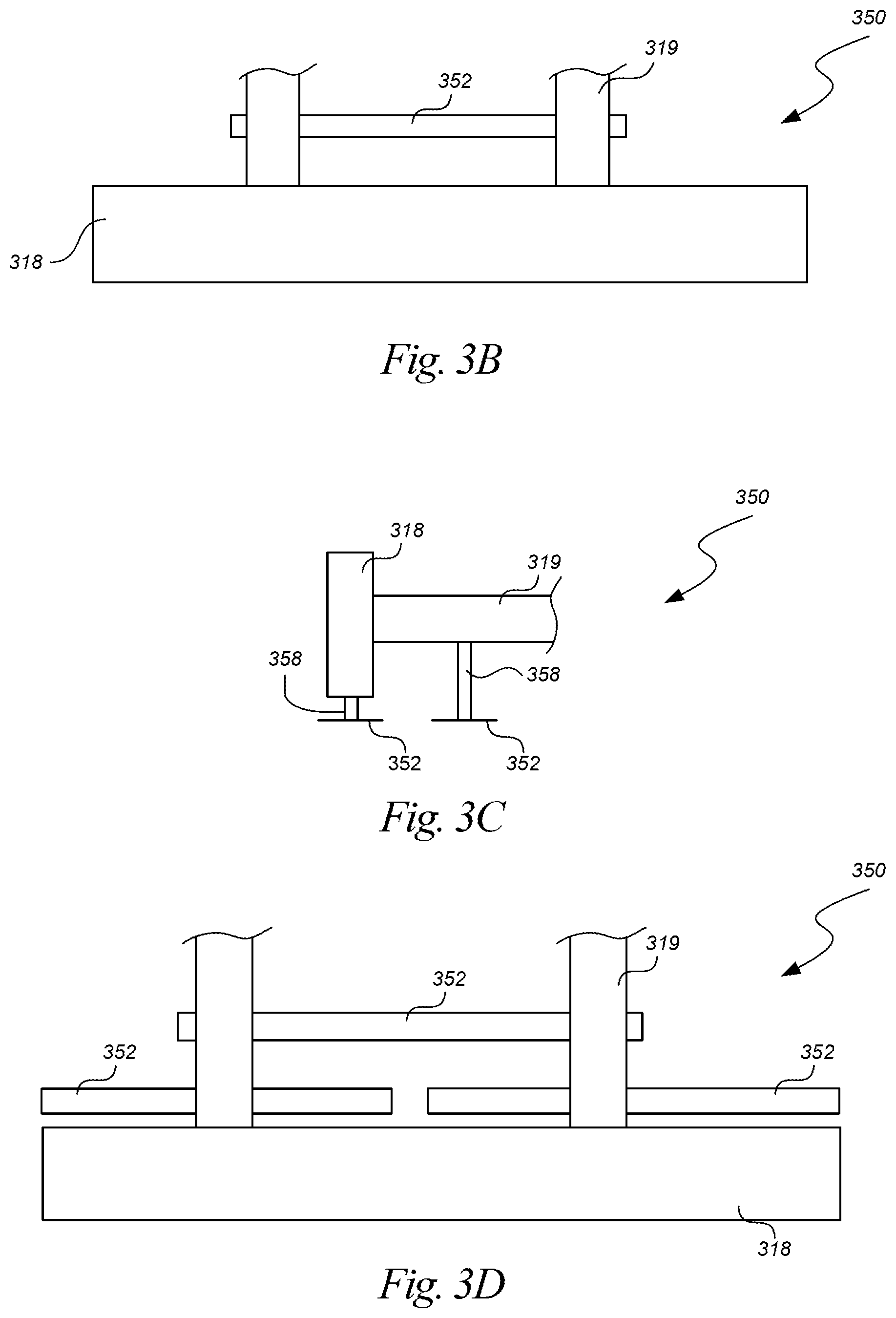
FIG. 3B is a partially schematic top view of another embodiment of a decarbonization system configured in accordance with embodiments of the technology.
FIG. 3C is a partially schematic side view of the decarbonization system depicted in FIG. 3B.
FIG. 3D is a partially schematic top view of a further embodiment of a decarbonization system configured in accordance with embodiments of the technology.
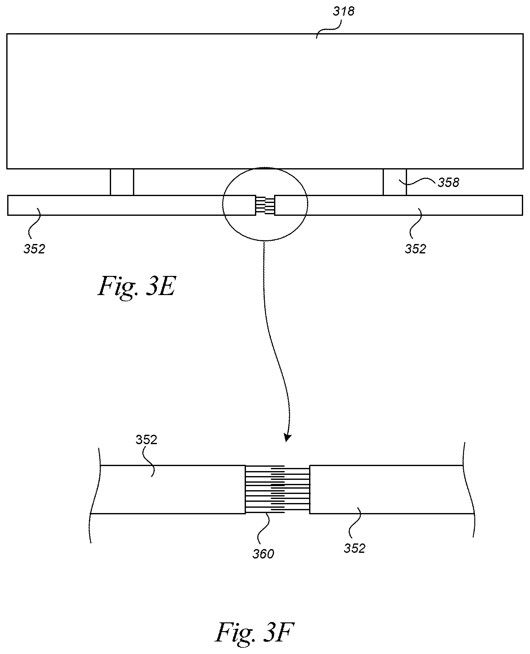
FIG. 3E is a partially schematic front view of another decarbonization system configured in accordance with further embodiments of the technology.
FIG. 3F is a partially schematic isometric view of a portion of the decarbonization system depicted in FIG. 3E.
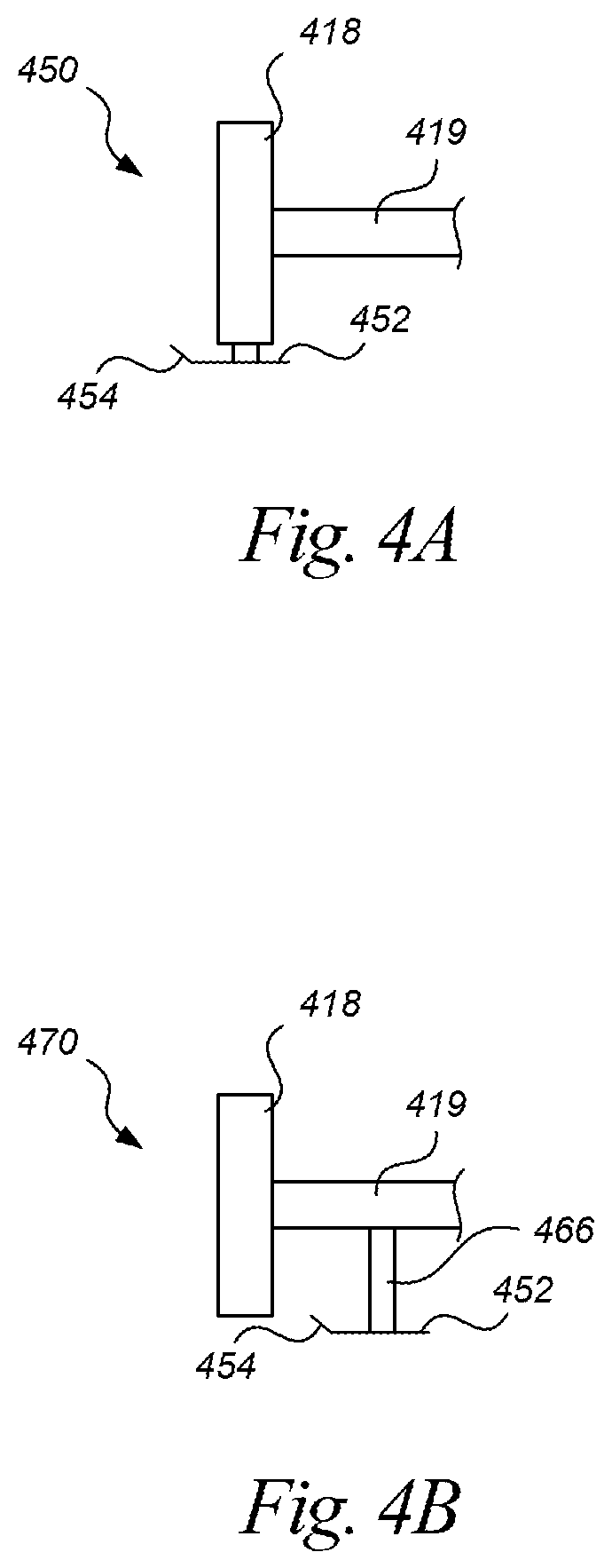
FIG. 4A is a partially schematic side view of one embodiment of a decarbonization system configured in accordance with embodiments of the technology.
FIG. 4B is a partially schematic side view of another embodiment of a decarbonization system configured in accordance with embodiments of the technology.
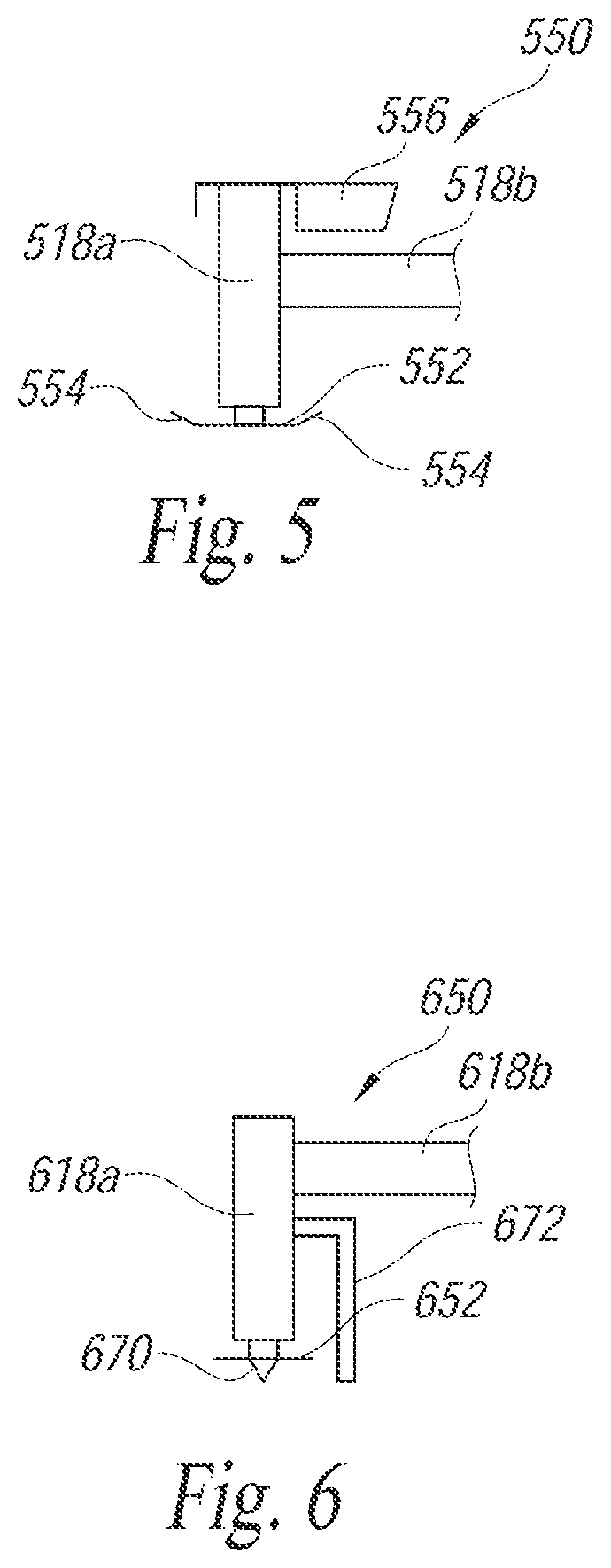
FIG. 5 is a partially schematic side view of a further embodiment of a decarbonization system configured in accordance with still further embodiments of the technology.
FIG. 6 is a partially schematic side view of still another embodiment of a decarbonization system configured in accordance with additional embodiments of the technology.
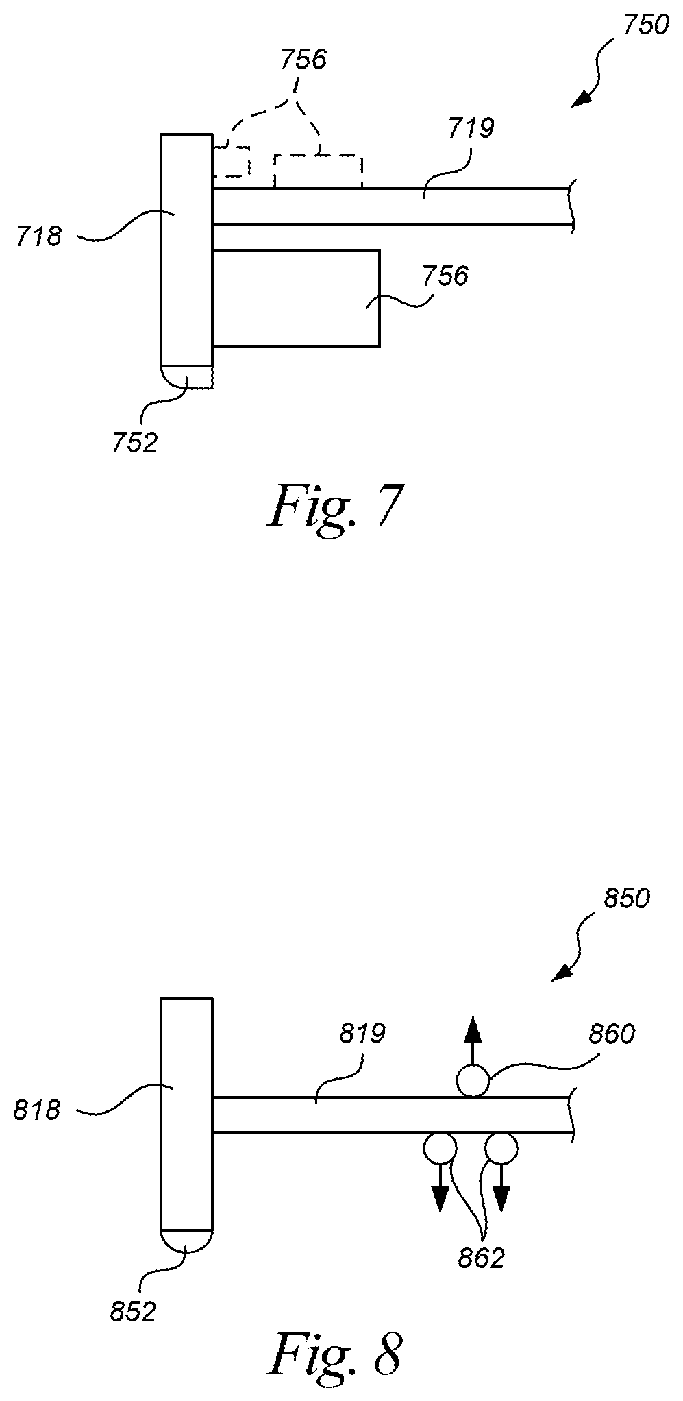
FIG. 7 is a partially schematic side view of another embodiment of a decarbonization system configured in accordance with embodiments of the technology.
FIG. 8 is a partially schematic side view of a further embodiment of a decarbonization system configured in accordance with embodiments of the technology.
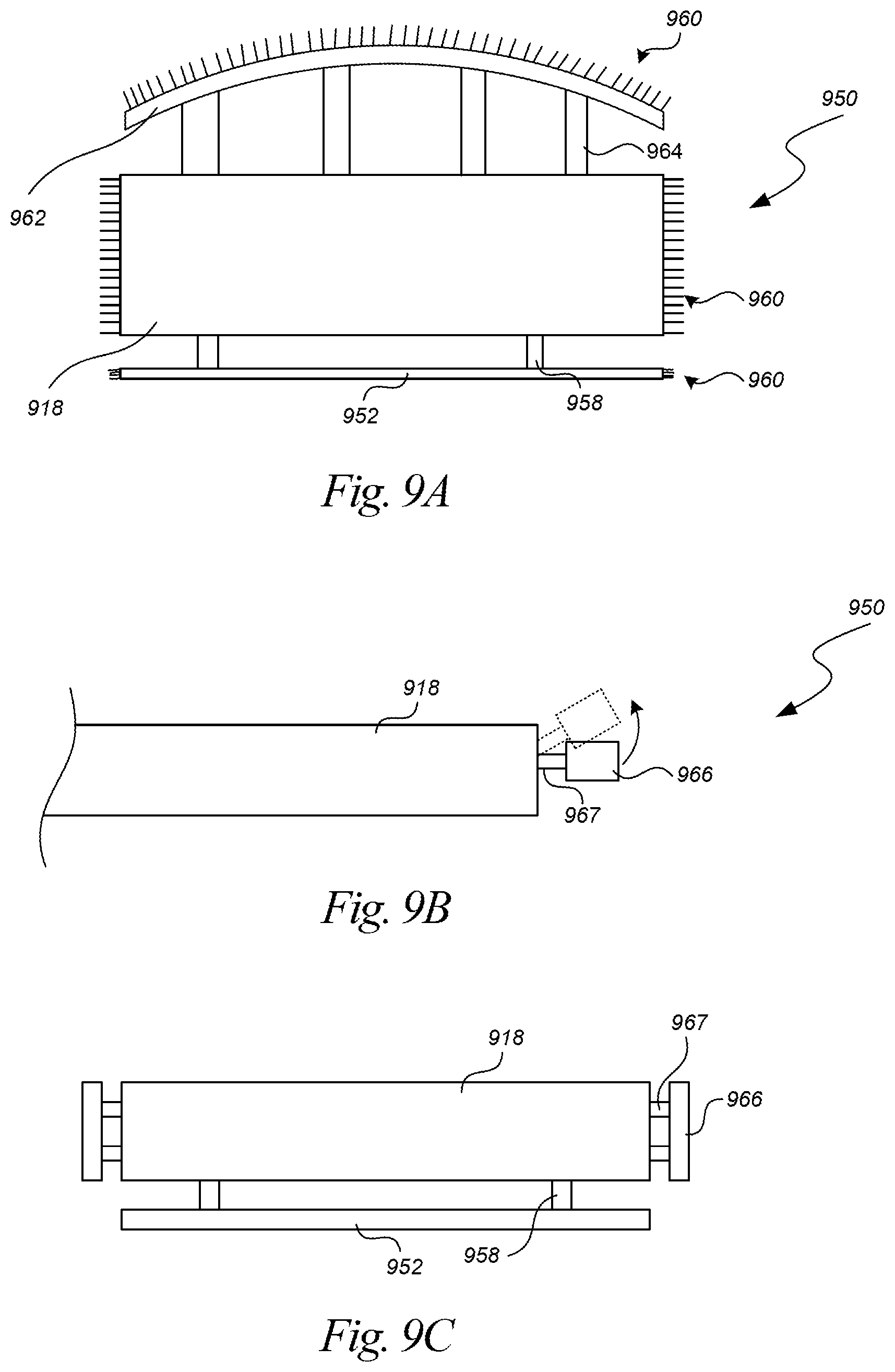
FIG. 9A is a partially schematic front view of another embodiment of a decarbonization system configured in accordance with embodiments of the technology.
FIG. 9B is a partially schematic top view of a further embodiment of a decarbonization system configured in accordance with embodiments of the technology.
FIG. 9C is a partially schematic front view of the decarbonization system depicted in FIG. 9B.
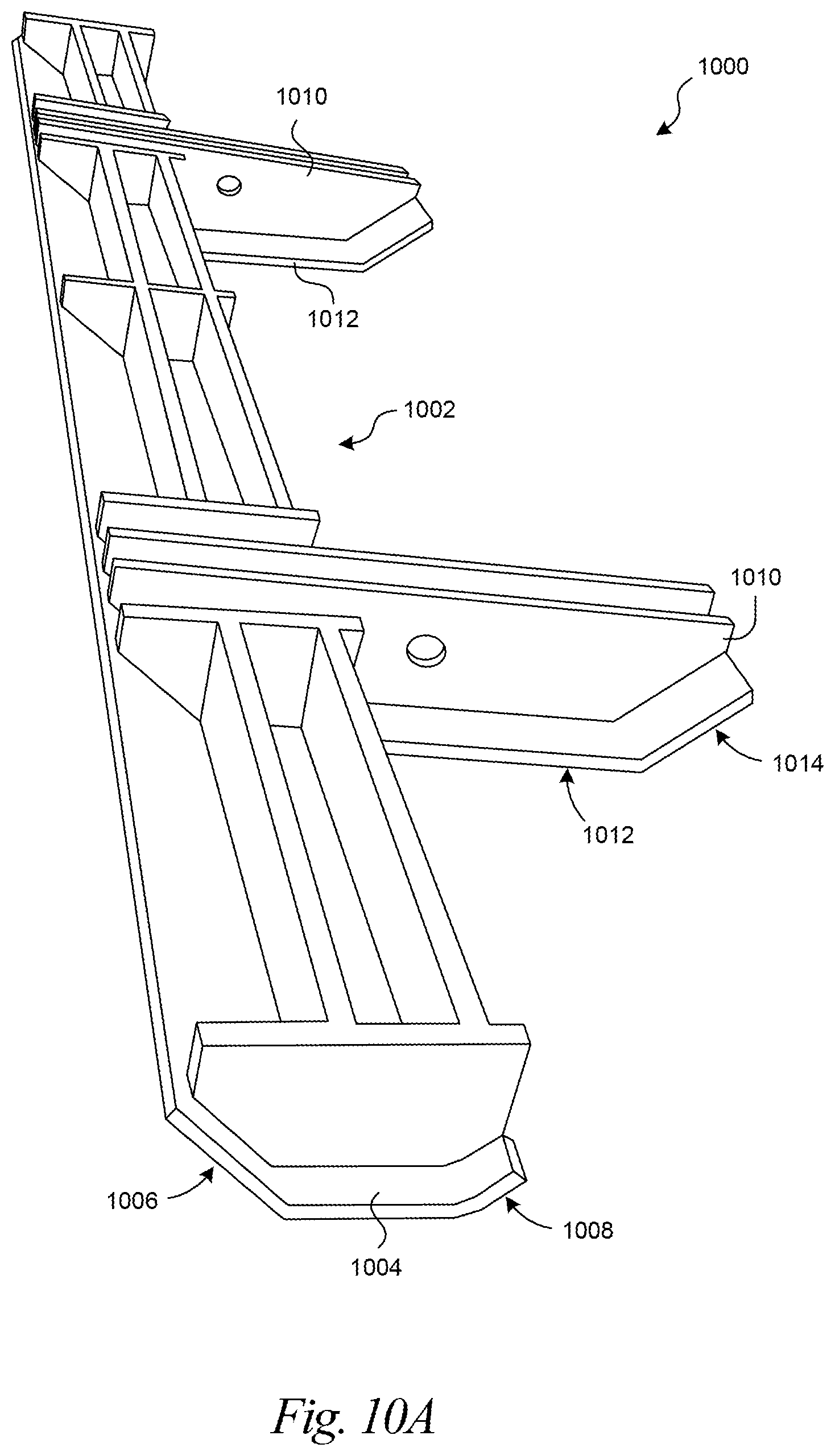
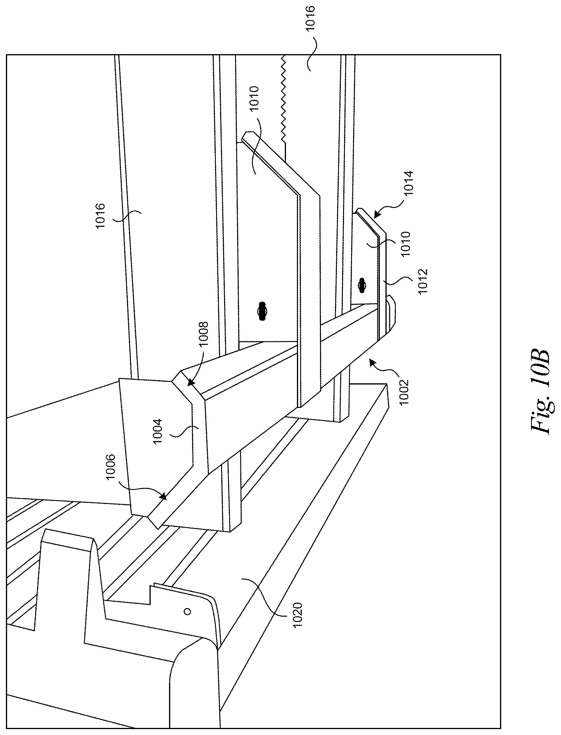
FIG. 10A depicts a partial side perspective view of one embodiment of a decarbonization system configured in accordance with further embodiments of the technology.
FIG. 10B depicts a side perspective view of the decarbonization system depicted in FIG. 10A and depicts one manner in which it may be coupled with a pushing ram.
FIG. 11 is a partially schematic front view of one embodiment of a decarbonization system configured in accordance with embodiments of the technology and depicts one manner in which it may engage a floor of a coke oven.
FIG. 12 is a partially schematic front view of another embodiment of a decarbonization system configured in accordance with embodiments of the technology and depicts one manner in which it may engage a floor of a coke oven.
FIG. 13 is a block diagram illustrating a method of decarbonizing a coke oven in accordance with embodiments of the technology.
FIG. 14 is a block diagram illustrating a method of operating a coke oven in accordance with embodiments of the technology.
DETAILED DESCRIPTION
The present technology is generally directed to methods of decarbonizing coking ovens, and associated systems and devices. In some embodiments, a method of operating and decarbonizing a coking oven can include inserting a charge of loose coal into the coking oven and heating the coal. The method can further include removing at least a portion of the charge, leaving behind coking deposits in the coking oven. At least a portion of the deposits can be continuously removed from the coking oven. For example, in some embodiments, at least a portion of the deposits can be removed each time a new charge of coal is inserted in the coking oven.
Specific details of several embodiments of the technology are described below with reference to FIGS. 1A-14. Other details describing well-known structures and systems often associated with coke ovens and decarbonizing have not been set forth in the following disclosure to avoid unnecessarily obscuring the description of the various embodiments of the technology. Many of the details, dimensions, angles, and other features shown in the Figures are merely illustrative of particular embodiments of the technology. Accordingly, other embodiments can have other details, dimensions, angles, and features without departing from the spirit or scope of the present technology. A person of ordinary skill in the art, therefore, will accordingly understand that the technology may have other embodiments with additional elements, or the technology may have other embodiments without several of the features shown and described below with reference to FIGS. 1A-14.
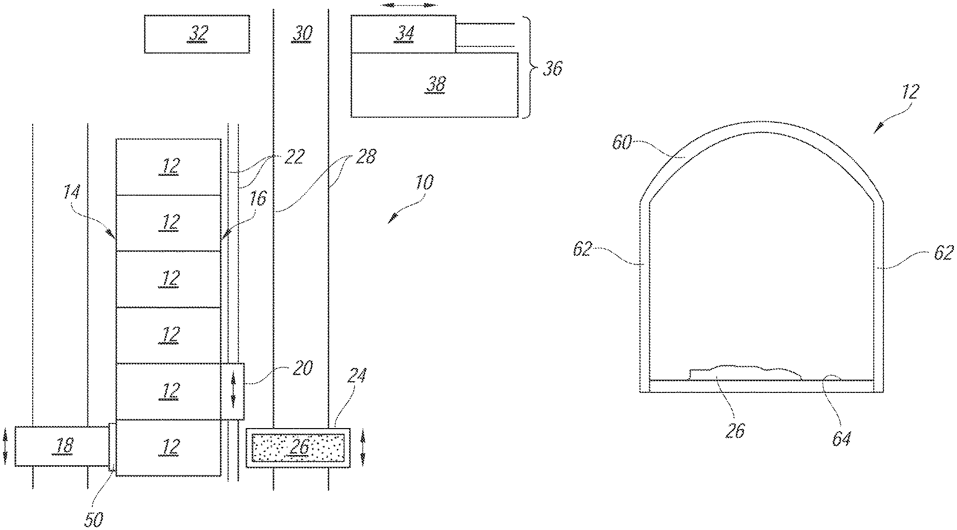
FIG. 1A is a plan schematic view of a coke oven battery 10 configured in accordance with embodiments of the technology. FIG. 1B is a front view of an individual coke oven 12 having coke deposits 26 therein and configured in accordance with embodiments of the present technology. Referring to FIGS. 1A and 1B together, the typical coke oven battery 10 contains a plurality of side-by-side coke ovens 12. Each of the coke ovens 12 can have a coal inlet end 14 and a coke outlet end 16 opposite the inlet end 14. Each individual coke oven 12 further includes an oven floor 64, a plurality of sidewalls 62, and an oven crown 60 coupled to the sidewalls 62 and atop a coking chamber.
The oven can receive coal, such as loose, non-stamp-charged coal, from the inlet end 14. The coal can be heated in the coke oven 12 until it is fully coked (typically 24-120 hours). An exit door removing device 20 can be positioned adjacent the outlet end 16 of the coke oven 12 and can remove an exit door of the coke oven 12. After removing the exit door, the door removing device 20 can be moved away from the outlet end 16 of the coke oven 12 along door removal rails 22. A retractable discharge (or "pushing") ram 18 positioned adjacent to the inlet end 14 of the coke oven 12 pushes the hot coke and/or deposits out of the coke oven 12. In several embodiments, the discharge ram 18 can include a ram head supported and driven by a ram arm. In some embodiments, all or part of the discharge ram 18 is adjustable via a hydraulic system capable of vertical movement. In some embodiments, the discharge ram 18 may include a device for removing an inlet end 14 oven door prior to pushing the coke/deposits out of the coke oven 12. As will be described in further detail below, the discharge ram 18 can include or be coupled to a decarbonization system 50 configured to remove the coke deposits 26 from the coke oven 12. In further embodiments, the decarbonization system 50 and coke-charging aspects of the system can each use separate, dedicated retractable rams.
In some embodiments, the decarbonization system 50 can provide high-pressure removal of the coke deposits 26 from the coke oven 12. For example, in some embodiments, as will be discussed in more detail below, the decarbonization system 50 can include various scoring and/or scraping features to break up the compacted deposits and/or remove the deposits from the oven. In some embodiments, the deposits 26 can be broken up and/or removed continuously. As used herein, the term "continuously" is used to indicate a routine breaking or removal of the deposits that occurs on a schedule more frequently than traditional annual oven cleaning. For example, continuous removal can indicate that the deposits 26 are removed from the coke oven 12 at least monthly, weekly, daily, or each time a new charge of coal is inserted in the coke oven 12, such as before, during, or after the charge is inserted or removed.
A hot car 24 can be positioned adjacent to the outlet end 16 of the coke oven 12 for collection of hot coke and/or deposits 26 pushed from the oven by the discharge ram 18. The "hot car" may comprise a flat push hot car, train, and/or a combined flat push hot car/quench car. Once the hot coke or deposits 26 are loaded onto the hot car 24, the car 24 can be transported on rails 28 to a quench car area 30. In the quench car area 30, the hot coke slab or deposits 26 on the hot car 24 can be pushed by a stationary pusher 32 onto a quench car 34. Once the quench car 34 receives the hot coke or deposits 26, the quench car 34 can be positioned in a quench station 36 wherein the hot coke or deposits 26 can be quenched with sufficient water to cool the coke or deposits 26 to below a coking temperature. Various embodiments may use a combined hot car/quench car that allows the hot coke or deposits 26 to be transported directly from the coke oven 12 to the quench station 36 using a single hot car. The quenched coke can then be dumped onto a receiving dock 38 for further cooling and transport to a coke storage area.
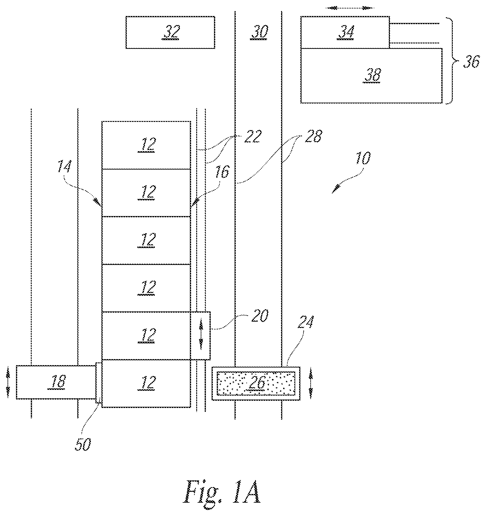
FIG. 2 is a front view of a decarbonization system 250 configured in accordance with embodiments of the technology. The decarbonization system 250 can include a pushing ram head 218 and one or more scraping plates 252 coupled to the ram head 218 by one or more couplers 258. The pushing ram head 218 can be coupled to a pushing or discharge ram such as the discharge ram 18 described above with reference to FIG. 1A. In various embodiments, the scraping plate 252 can include a generally rigid surface made, for example, of steel, steel alloy, ceramic, or other refractory materials that are suitable for scraping or otherwise pushing coking deposits from a coke oven. The rigid surface may include one or more various grooves or scraping projections presented in one or more different scraping patterns. In such embodiments, one or more patterns of scraping projections may be used to provide increased localized pressure on the coking deposits. In other embodiments, surfaces of the scraping plate 252 are covered or at least partially embedded with abrasive materials, including ceramics, aluminum oxides, rubies, sapphires, diamonds, and the like. In some embodiments, the scraping plate 252 can have a vertical thickness from about 0.25 inch to about 3 inches, and in particular embodiments, has a thickness of about 0.75 inch. In various embodiments, the scraping plate 252 can extend across the entire width of the oven or a portion of the oven. In some embodiments, one or more scraping plates 252 may be coupled with the bottom and/or one or both sides of the ram head 218. It is further contemplated that embodiments of the decarbonization system 250 may position the scraping plates 252 behind the ram head 218, such as beneath a pusher ram arm that extends from the ram head 218.
In some embodiments, the couplers 258 are movable to allow the scraping plate 252 to vertically adjust to follow the contour of the oven floor. For example, in some embodiments, the couplers 258 can include a spring-loaded or hydraulic feature to provide scraping plate 252 adjustability. In further embodiments, the couplers 258 can be fixed to prevent such adjustability. In some embodiments, if the oven floor is not level, the scraping plate 252 can ride over high points and fill in low points with deposits, providing the benefit of keeping a thin, protective, and lubricating layer of clinker or other deposits on the floor.
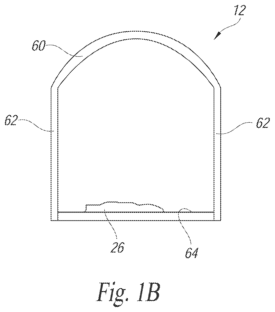
FIG. 3A is a front view of a decarbonization system 350 configured in accordance with further embodiments of the technology. The decarbonization system 350 includes several features of the decarbonization system 250 described above. For example, the decarbonization system 350 includes a pushing ram head 318 configured to push coke and/or coking deposits from a coke oven. The decarbonization system 350 further includes a plurality of scraping plates 352 coupled to the pushing ram head 318 by a plurality of couplers 358. While the illustrated embodiment illustrates two scraping plates 352 oriented side-by-side across the width of the pushing ram head 318, in further embodiments, the decarbonization system 350 can include any number of scraping plates 352 in side-by-side, angled, or other configurations across the pushing ram head 318. In some embodiments, using multiple scraping plates 352 can allow the decarbonization system 350 to more finely follow the contours of a non-level oven floor. Further, while the illustrated embodiment illustrates a single coupler 358 attaching each scraping plate 352 to the pushing ram head 318, in further embodiments, multiple couplers per scraping plate 352 may be used or the scraping plates 352 can be coupled to or integrate directly with the pushing ram head 318 without an intermediate coupler.
FIG. 3B is a top, plan view of a decarbonization system 350 configured in accordance with further embodiments of the technology. In this embodiment, the decarbonization system 350 is similar to the decarbonization system 350 depicted in FIG. 3A. However, FIG. 3B depicts an embodiment where the decarbonization system includes an additional scraping plate 352 that is coupled with the pushing ram arm 319. With reference to FIG. 3C, a side elevation view of the decarbonization system 350 is depicted. In this embodiment, the additional scraping plate 352 is coupled with the pushing ram arm 319 with one or more couplers 358. With reference to FIG. 3A, the forward two scraping plates 352 are oriented side-by-side across the width of the pushing ram head 318, which forms a gap between the opposing ends of the forward two scraping plates 352. In the embodiment depicted in FIGS. 3B and 3C, the additional scraping plate 352 is positioned rearwardly from the forward two scraping plates 352 and oriented so that a length of the additional scraping plate 352 is positioned behind the gap. Accordingly, the three scraping plates 352 substantially cover the width of the pushing ram head 318. In still other embodiments, such as depicted in FIG. 3D, it is contemplated that the forward two scraping plates 352 could be coupled with the pushing ram arms 319, rather than the pushing ram head 318, as depicted in FIGS. 3A-3C.
FIGS. 3E and 3F depict another embodiment of the decarbonization system 350 configured in accordance with further embodiments of the technology. In this embodiment, the decarbonization system 350 is similar to the decarbonization system 350 depicted in FIGS. 3A-3D. However, FIGS. 3E and 3F depict an embodiment where a gap between the opposing ends of the forward two scraping plates 352 is spanned by one or more resiliently deformable scraping features or, in the depicted embodiment, a plurality of elongated bristles 360. In the depicted embodiment, the elongated bristles 360 extend outwardly from the opposite end portions of the forward two scraping plates 352 such that lengths of opposing elongated bristles 360 pass or overlap one another. In some embodiments, the elongated bristles 360 are formed from steel, a steel alloy, or other materials capable of withstanding the temperatures of the coke oven and, while deformably resistant, provide an ability to scrape and remove at least some of the coking deposits in which they come into contact. The elongated bristles 360 are depicted as being straight and aligned in a parallel, spaced-apart, fashion. However, it is contemplated that the elongated bristles could be curved, angular, looped, or other known shapes. It is also contemplated that the elongated bristles 360 could overlap one another or angle upwardly or downwardly with respect to the forward two scraping plates 352. In various embodiments the elongated bristles 360 can be replaceable. In such embodiments, sections or portions of the elongated bristles 360 may be removably or permanently secured in position.
FIG. 4A is a side view of a decarbonization system 450 configured in accordance with embodiments of the technology. The decarbonization system 450 includes several features generally similar to the decarbonization systems described above. For example, a scraping plate 452 is coupled to a pushing ram head 418. The pushing ram arm 419 can support and retractably drive the pushing ram head 418. In the illustrated embodiment, the scraping plate 452 includes a beveled edge 454 to define a scraping ski with a single shovel and tip. In various embodiments, the beveled edge 454 can be on either the pushing side or the following side of the scraping plate 452. In some embodiments, the beveled edge can allow the scraping plate 452 to ride along the oven floor without tearing up or digging into the floor material (e.g., brick). The beveled edge 454 may be smooth or include one or more various grooves or scraping projections presented in one or more different scraping patterns. A plurality of scraping plates 452 may be positioned adjacent one another in one of various patterns, side by side, or in a stacked, following configuration.
FIG. 4B is a partially schematic side view of a decarbonization system 470 configured in accordance with further embodiments of the technology. The decarbonization system 470 is generally similar to the decarbonization system 450 described above with reference to FIG. 4A. However, in the embodiment illustrated in FIG. 4B, the scraping plate 452 is coupled to (e.g., descends from) a pushing ram arm 419 instead of the pushing ram head 418. The pushing ram arm 419 can support and retractably drive the pushing ram head 418. The scraping plate 452 can be coupled to the pushing ram arm 419 by a coupler 466. The coupler 466 can be fixed or movable, such as spring-loaded. In particular embodiments, the coupler 466 can provide an adjustable height mechanism to adjust a height of the scraping plate 452 relative to the pushing ram head 418 and the oven floor. In various embodiments, a lower surface of the scraping plate 452 can be generally coplanar or slightly above or below a lower surface of the pushing ram head 418. The relative height of the pushing ram head 418 and scraping plate 452 can be selected to best smooth and clean the oven floor without interfering with coke-pushing operations. While the scraping plate 452 is shown on a following side of the pushing ram head 418, in further embodiments, it can be on a leading side of the pushing ram head 418. Further, the scraping plate 452 or other scraping or scoring device can alternatively or additionally be coupled to the pushing ram head 418 or other location in the decarbonization system 470.
Embodiments of the decarbonization system 470 may be provided with one or more scraping plates 452 having a wide array of different configurations. For example, a scraping plate 452, coupled with the coupler 466, may be provided with a pair of beveled edges 454, positioned at opposite end portions of the scraping plate 452. In this manner, a beveled edge 454 defines a leading edge portion of the scraping plate in either direction that the decarbonization system 470 is moved along a length of the oven. In some embodiments, the pair of beveled edges 454 may be provided with lengths that are equal or dissimilar to one another. Embodiments of the scraping plates 452 may present the beveled edges 454 to extend upwardly from a generally horizontal base plate of the scraping plate 452 at an angle approximating forty five degrees. However, other embodiments may present the beveled edges to extend upwardly at an angle that is at least slightly less than or greater than forty five degrees. Similarly, embodiments of the scraping plates 452 may include chamfered or rounded edges where the beveled edges 454 meet the horizontal base plate, depending on the desired level of ease with which the scraping plates 452 engage edges or irregular surfaces of the coking deposits and the oven floor.
FIG. 5 is a side view of a decarbonization system 550 configured in accordance with further embodiments of the technology. Like the systems described above, the decarbonization system 550 includes a scraping plate 552 coupled to a pushing ram head 518. The scraping plate 552 includes beveled edges 554 on both pushing and following sides of the scraping plate 552 to define a scraping ski with a pair of opposing shovels and tips. One or both of the beveled edges 554 may be smooth or include one or more various grooves or scraping projections presented in one or more different scraping patterns. A plurality of scraping plates 552 may be positioned adjacent one another in one of various patterns, side by side, or in a stacked, following configuration.
The decarbonization system 550 can further include a weight or ballast 556 configured to weigh down the decarbonization system 550 against the coke oven floor. In various embodiments, the ballast 556 can be coupled to a pushing ram (e.g., the pushing ram head 518 or other portion of a pushing ram) or the scraping plate 552. In further embodiments, there can be more or fewer ballasts 556. In particular embodiments, the ballast 556 comprises steel, a steel alloy, or other refractory materials. In some embodiments, the pushing ram head 518 or scraping plate 552 can be uniformly or non-uniformly weighted to achieve consistent or varied downward pressure as desired.
FIG. 6 is a side view of a decarbonization system 650 configured in accordance with additional embodiments of the technology. The decarbonization system 650 includes a generally flat (e.g., non-beveled) scraping plate 652 coupled to a pushing ram head 618. In embodiments having more than one scraping plate 652, a combination of beveled and non-beveled plates can be used.
The decarbonization system 650 further includes various scoring features to create grooves or breaks in the coking deposits. For example, in the illustrated embodiment, the decarbonization system 650 includes scoring teeth 670 along a bottom surface of the scraping plate 652 and a scoring bar 672 extending outward and downward from the pushing ram head 618. The teeth 670 and bar 672 can groove or score the surface of the coke, leading to fractures that break apart the highly-compacted deposits into more easily removable pieces. In still further embodiments, other scoring features such as a wheel, impactor, cutter, etc. can be used.
In some embodiments, the deposits having been broken apart by the scoring features can be more readily pushed or otherwise removed from the coke oven. In various embodiments, the scoring features can be used in conjunction with pushing the deposits from the oven, or can be used separately. For example, in some embodiments, the deposits can be scored each time the deposits are scraped from the oven. In further embodiments, scoring the deposits can occur more frequently than scraping the deposits because the scoring reduces the need for high-pressure scraping. In other embodiments, scoring the deposits can occur less frequently than scraping the deposits. In still further embodiments, a scoring feature may be coupled to a coke pushing ram while the scraping plate 652 is coupled to a separate decarbonization pushing ram that follows the coke pushing ram.
The scoring features can be positioned on a pushing and/or following side of the pushing ram head 618, the scraping plate 652, on another device altogether (e.g., a pushing ram arm), or in a combination of these positions. Further, various embodiments can include scoring features across (or partially across) the width and/or depth of the pushing ram head 618. Additionally, various scoring features may be used individually or in combination. For example, while the decarbonization system 650 includes both scoring teeth 670 and a scoring bar 672, in further embodiments, only one of these scoring features (or other scoring features) may be used.
FIG. 7 is a side view of a decarbonization system 750 configured in accordance with further embodiments of the technology. The decarbonization system 750 includes a scraping plate 752 coupled to a pushing ram head 718 that is driven by a pushing ram arm 719. The scraping plate 752 includes at least one rounded edge. Like the beveled scraping plates described above, the rounded edge on the scraping plate 752, shown in FIG. 7, can prevent the scraping plate 752 from causing tear-out in the oven floor. Instead, the rounded edge can scrape or push the coking deposits from the oven floor while riding on the floor. While the rounded edge is shown on the pushing side of the pushing ram head 718, in further embodiments, it can be on the following side.
The decarbonization system 750 can further include an optional weight or ballast 756 to pressure the pushing ram head 718 and scraping plate 752 downward against the floor to improve contact and deposit clean-out. For example, in the illustrated embodiment, the ballast 756 is shown coupled to the pushing ram head 718. In further embodiments, one or more ballasts 756 can additionally or alternately be coupled to the pushing ram arm 719, the scraping plate 752, or can be integral to any of these features. Some example locations for alternate or additional placement of the ballasts 756 are shown in dashed lines.
FIG. 8 is a side view of a decarbonization system 850 configured in accordance with still further embodiments of the technology. The decarbonization system 850 includes a scraping plate 852 coupled to a pushing ram head 818 that is driven by a pushing ram arm 819. The scraping plate 852 can be rounded on both the pushing and following sides to prevent tear-out on the oven floor during both extension and retraction motions of the pushing ram arm 819 relative to the coking chamber. In some embodiments, the scraping plate 852 may not be provided in a planar, plate-like configuration. Rather, some embodiments of the decarbonization system may use an elongated pipe having a plurality of holes disposed along a length of the pipe. An oxidant, such as air or oxygen, may be directed through the pipe and the holes at a rate that burns at least some, if not a substantial portion, of the coking deposits.
The decarbonization system 850 can further include a plurality of rollers (e.g., an upper roller 860 and lower rollers 862) attached to a pushing support structure (e.g., a pushing/charging machine, not shown) that is configured to support and allow for retractable movement of the pushing ram arm 819. In addition, or as an alternative to the weight systems described above which encourage contact between the scraping plate 852 and the oven floor, in some embodiments, the rollers 860, 862 can be adjusted to provide a generally similar force. For example, the upper roller 860 can be adjusted upward and/or the lower rollers 862 can be adjusted downward (in the direction of the arrows) to add downward force to the cantilevered pushing ram head 818 and/or scraping plate 852. The same relationship can apply regardless of whether the scraping plate 852 is attached to the pushing ram head 818 as shown or directly to the pushing ram arm 819 as shown in FIG. 4B.
FIG. 9 is a front view of a decarbonization system 950 configured in accordance with embodiments of the technology. The decarbonization system 950 can include a pushing ram head 918 and one or more scraping plates 952 coupled to the ram head 918, or one or more pushing ram arms (not depicted), by one or more couplers 958. The pushing ram head 918 can be coupled to a pushing or discharge ram such as the discharge ram 18 described above with reference to FIG. 1A. In various embodiments, the scraping plate 952 will be constructed in a manner similar to other scraping plates or features described above. However, in certain embodiments, one or more resiliently deformable scraping features or, in the depicted embodiment, a plurality of elongated bristles 960 extend outwardly from different features of the decarbonization system 950. For example, the elongated bristles 960 are depicted as extending outwardly from the opposite end portions of the scraping plate 952 and opposite side portions of the pushing ram head 918. When positioned as depicted, the elongated bristles 960 follow contours of the sidewalls of the coke oven as the decarbonization system 950 is pushed and retracted through the coke oven. The deformable nature of the elongated bristles 960 allow the elongated bristles 960 to follow irregular surfaces better than rigid scraping features. Similarly, elongated bristles may be positioned to extend upwardly from a support frame 962 that is supported by connectors 964 on top of the pushing ram head 918 or pushing ram arms 919. In this manner, the elongated bristles 960 may be positioned to follow contours of the crown of the coke oven as the decarbonization system 950 is pushed and retracted through the coke oven. In some embodiments, the elongated bristles 960 are formed from steel, a steel alloy, or other materials capable of withstanding the temperatures of the coke oven and, while deformably resistant, provide an ability to scrape and remove at least some of the coking deposits in which they come into contact. The elongated bristles 960 are depicted as being straight and aligned in a parallel, spaced-apart, fashion. However, it is contemplated that the elongated bristles could be curved, angular, looped, or other known shapes.
FIG. 9B and FIG. 9C depict another embodiment of the decarbonization system 950 configured in accordance with embodiments of the technology. The depicted embodiment of the decarbonization system 950 includes a pushing ram head 918 and one or more scraping plates 952 coupled to the ram head 918, or one or more pushing ram arms (not depicted), by one or more couplers 958. In the depicted embodiment, the decarbonization system 950 includes resiliently deformable scraping features or, in the depicted embodiment, resilient scraping plates 966 that are connected to opposite side portions of the pushing ram head 918 by resiliently deformable couplers 967. When positioned as depicted, the scraping plates 960 follow contours of the sidewalls of the coke oven as the decarbonization system 950 is pushed and retracted through the coke oven. The deformable nature of the resiliently deformable couplers 967 allow the scraping plates 960 to extend and retract from the pushing ram head 918 and follow varying distances from the decarbonization system 950 and the coke oven walls. The scraping plates 960 may be formed from materials similar to those used to form the scraping plate 952, such as steel, steel alloys, ceramic, and the like. In some embodiments, the resiliently deformable couplers 967 are formed from steel, a steel alloy, or other materials capable of withstanding the temperatures of the coke oven and, while deformably resistant, sufficiently durable to support the scraping plates 960 while they scrape the sidewalls of the coke oven.
FIG. 10A and FIG. 10B depict an embodiment of a scraper 1000 that may be used with a decarbonization system configured in accordance with embodiments of the technology. In the depicted embodiment, the scraper 1000 includes an elongated scraper body 1002 having a scraping plate 1004 having a forward beveled edge 1006 and a rearward beveled edge 1008. In various embodiments, the scraping plate 1004 can include a generally rigid surface made, for example, of steel, steel alloy, ceramic, or other refractory materials that are suitable for scraping or otherwise pushing coking deposits from a coke oven. The rigid surface may include one or more various grooves or scraping projections presented in one or more different scraping patterns. In such embodiments, one or more patterns of scraping projections may be used to provide increased localized pressure on the coking deposits. In other embodiments, surfaces of the scraping plate 1004 are covered or at least partially embedded with abrasive materials, including ceramics, aluminum oxides, rubies, sapphires, diamonds, and the like. In some embodiments, the scraping plate 1004 can have a vertical thickness from about 0.25 inch to about 3 inches, and in particular embodiments, has a thickness of about 0.75 inch. In various embodiments, the scraping plate 1004 can extend across the entire width of the oven or a portion of the oven.
The scraper 1000 further includes a plurality of elongated scraper shoes 1010 coupled to the scraper body 1002 so that the scraper shoes 1010 are horizontally spaced apart from one another. In various embodiments, the scraper shoes 1010 extend rearwardly and perpendicularly from the scraper body 1002. The scraper shoes 1010 include scraping skis 1012 that include a generally rigid surface made, for example, of steel, steel alloy, ceramic, or other refractory materials that are suitable for scraping or otherwise pushing coking deposits from a coke oven. As with the scraping plate, the rigid surface of the scraping skis 1012 may include one or more various grooves or scraping projections presented in one or more different scraping patterns and may be covered or at least partially embedded with abrasive materials, including ceramics, aluminum oxides, rubies, sapphires, diamonds, and the like. In some embodiments, the scraping skis 1012 have a vertical thickness from about 0.25 inch to about 3 inches, and in particular embodiments, has a thickness of about 0.75 inch. The scraping skis 1012 include a forward beveled edge (not depicted) and a rearward beveled edge 1014. The forward beveled edge and rearward beveled edge 1014 may extend upwardly from the bottom of the scraping skis 1012 at various angles according to the intended scraping operations. In the depicted embodiment, the forward beveled edge and rearward beveled edge 1014 extend upwardly from the base of the scraping ski at forty-five degree angles. With reference to FIG. 10B, the scraper 1000 may be coupled to the ram head arms 1016 of a pushing ram by one or more couplers (not depicted). It is contemplated, however, that the scraper 1000 be coupled to a pushing ram head 1020.
In various embodiments, bottom surfaces of the scraping skis 1012 are positioned to be co-planar with one another. In some embodiments, the bottom surfaces of the scraping surfaces 1012 are positioned to be co-planar with a bottom surface of the scraper body 1002. In such instances, the scraper 1000 has a uniform bottom surface and any weight received by the coke oven floor from the scraper 1000 is evenly disbursed across the coke oven floor 64. FIG. 11 depicts a front schematic representation of such embodiments. In such embodiments, however, it is contemplated that the crown portions of the sole flues 66 may be damaged under the weight of the decarbonization system. In other embodiments, however, the bottom surfaces of the scraping surfaces 1012 are positioned to be parallel but beneath a plane in which the bottom surface of the scraper body 1002 resides. In some embodiments, the two planes may be separated by less than an inch. In other embodiments, it may be by two or three inches, depending on the conditions present in the coking oven. FIG. 12 depicts such an embodiment. The scraper shoes 1010 are positioned along a length of the scraper body 1002 so that the scraper shoes 1010 are positioned above, and aligned with, sole flue walls 68 associated with the sole flues 66. In this manner, a substantial portion of any weight received by the coke oven floor 64 from the scraper 1000 is received by the sole flue walls 68 of the sole flues 66. Moreover, greater support is afforded to the decarbonizing system and the sole flues 66 are less likely to be damaged by scraping operations. Such embodiments of the scraper 1000 further provide the opportunity to have one or more resiliently deformable scraping features or, in the depicted embodiment, a plurality of elongated bristles 1060 extend outwardly from different features of the scraper 1000. For example, the elongated bristles 1060 are depicted as extending outwardly from the bottom surface of the scraping plate 1004 on either side of the scraping shoes 1010. In this manner, additional scraping of coking deposits may occur without transferring more weight to the other areas of the coke oven floor 64.
FIG. 13 is a block diagram illustrating a method 1300 of decarbonizing a coke oven of coking deposits in accordance with embodiments of the technology. At bock 1302, the method 1300 can include processing a charge of coal in the coke oven. In several embodiments, the coke oven comprises a floor, a crown, and a plurality of sidewalls connecting the floor and the crown. In some embodiments, the charge of coal comprises loose, non-stamp-charged coal. At block 1304, the method 1300 can include removing the charge from the coke oven. At block 1306, the method 1300 can include scraping at least a portion of coking deposits from the coke oven floor, wherein the scraping is performed at least monthly. In various embodiments, the scraping can occur simultaneously with, before, or after the charge-removing step. In particular embodiments, the scraping can occur at least weekly, at least daily, or each time the charge is inserted or removed from the coke oven. In various embodiments, the scraping is performed by running a scraper along or over the coke oven floor one or a plurality of times.
In various embodiments, the scraping can be performed using any of the decarbonization systems described above. For example, in some embodiments, the scraping includes using a scraper having at least one rounded or beveled edge proximate to the coke oven floor. In further embodiments, the scraping includes using a scraper having one or more plates that substantially follow a contour of the coke oven floor during scraping. In particular embodiments, the scraper is at least partially made of steel, a steel alloy, or a ceramic material. In some embodiments, the scraping is performed by a scraper including a ram head having a ballast coupled thereto. In some embodiments, the method 1300 can further include scoring a surface of the deposits using any scoring feature such as those described above.
FIG. 14 is a block diagram illustrating a method 1400 of operating a coking oven in accordance with embodiments of the technology. At blocks 1402 and 1404, the method 1400 can include inserting a charge of loose coal into the coking oven and heating the coal. At block 1406, the method 1400 can include removing at least a portion of the charge, leaving behind coking deposits in the coking oven. At block 1408, the method 1400 can include continuously removing at least a portion of the deposits from the coking oven. For example, in various embodiments, the deposits can be removed from the coking oven at least daily or each time a new charge of coal is inserted in the coking oven. In some embodiments, the method can further include maintaining a substantially level surface on a floor of the coking oven.
EXAMPLES
The following Examples are illustrative of several embodiments of the present technology.
1. A method of decarbonizing a coke oven of coking deposits, the method comprising: processing a charge of coal in the coke oven, wherein the coke oven comprises a plurality of interior surfaces including a floor, a crown, and sidewalls that extend between the floor and the crown; removing the charge from the coke oven; and removing coking deposits from the coke oven, while removing the charge from the coke oven.
2. The method of example 1 wherein removing coking deposits from the coke oven comprises scraping at least a portion of the coking deposits with a scraper operatively coupled to a pushing ram.
3. The method of example 1 wherein removing coking deposits from the coke oven comprises scraping the coking deposits with a scraper having at least one rounded or beveled edge adjacent at least one interior surface of the coke oven.
4. The method of example 1 wherein removing coking deposits from the coke oven comprises scraping the coking deposits with a scraper having one or more plates that substantially follow a contour of at least one of the interior surfaces of the coke oven during scraping.
5. The method of example 1, further comprising scoring a surface of the coking deposits.
6. The method of example 1 wherein removing coking deposits from the coke oven comprises running a scraper along at least one interior surface of the coke oven a single time, whereby the scraper is pushed along a length of the coke oven and then retracted along the length of the coke oven.
7. The method of example 1 wherein removing coking deposits from the coke oven comprises running a scraper over at least one interior surface of the coke oven a plurality of times.
8. The method of example 7 wherein removing coking deposits from the coke oven comprises scraping the coking deposits with a scraper comprised of at least one deformably resilient scraping feature that substantially follows a contour of at least one of the interior surfaces of the coke oven during scraping.
9. The method of example 1 wherein removing coking deposits from the coke oven comprises scraping the coking deposits with a scraper comprised of steel, a steel alloy, or ceramics.
10. The method of example 1 wherein removing coking deposits from the coke oven comprises scraping the coking deposits with a scraper comprised of an abrasive.
11. The method of example 1 wherein removing coking deposits from the coke oven comprises scraping the coking deposits with a scraper operatively coupled to a pushing ram head of a pushing ram.
12. The method of example 11 wherein a weight is operatively coupled with the pushing ram.
13. The method of example 1 wherein removing coking deposits from the coke oven comprises scraping the coking deposits with a scraper operatively coupled to a pushing ram arm of a pushing ram.
14. The method of example 13 wherein a weight is operatively coupled with the pushing ram.
15. The method of example 1 wherein removing coking deposits from the coke oven comprises scraping coking deposits from a plurality of interior surfaces of the coke oven with a plurality of scrapers operatively coupled to a pushing ram.
16. The method of example 1 wherein removing coking deposits from the coke oven comprises scraping the coking deposits with a scraper comprised of at least one deformably resilient scraping feature that substantially follows a contour of at least one of the interior surfaces of the coke oven during scraping.
17. The method of example 16 wherein the at least one deformably resilient scraping feature includes a plurality of elongated bristles operatively coupled to a pushing ram such that free end portions of the bristles are directed toward the at least one interior surface of the coke oven.
18. The method of example 16 wherein the at least one deformably resilient scraping feature includes at least one elongated scraping bar operatively coupled to a pushing ram with at least one resiliently deformable hinge such that a leading edge portion of the at least one elongated scraping bar is positioned adjacent to the at least one interior surface of the coke oven.
19. The method of example 16 wherein the scraper includes a plurality of deformably resilient scraping features that substantially follow contours of a plurality of the interior surfaces of the coke oven during scraping.
20. The method of example 1 wherein removing coking deposits from the coke oven comprises scraping the coking deposits with a plurality of scrapers operatively coupled with a pushing ram.
21. The method of example 20 wherein the plurality of scrapers include at least two elongated scrapers operatively coupled with a pushing ram such that the elongated scrapers are positioned to be side by side one another with lengths of the scrapers extending perpendicular to a length of the coke oven during scraping.
22. The method of example 21 wherein the elongated scrapers are positioned to be coaxially aligned with one another and horizontally spaced apart to define a gap between the elongated scrapers.
23. The metho
References
-
app.knovel.com/hotlink/pdf/id:kt004QMGV6/instrumentation-reference-2/ditigal-video
-
researchgate.net/publication/263887759_A_review_on_stamped_charging_of_coals
-
dofasco.arcelormittal.com/-/media/Files/A/Arcelormittal-Canada/material-safety/metallurgical-coke.pdf
-
people/duke.edu/-hpgavin/SystemID/References/Astrom-Feedback-2006.pdf
-
forum.allaboutcircuits.com/threads/what-is-dead-band-control.4728
-
renold/com/upload/renoldswitzerland/conveyor_chain_-_designer_guide.pdf
-
epa.ohio.gov/portals/27/transfer/ptiApplication/mcc/new/262504.pdf
D00000
D00001
D00002
D00003
D00004
D00005
D00006
D00007
D00008
D00009
D00010
D00011
D00012
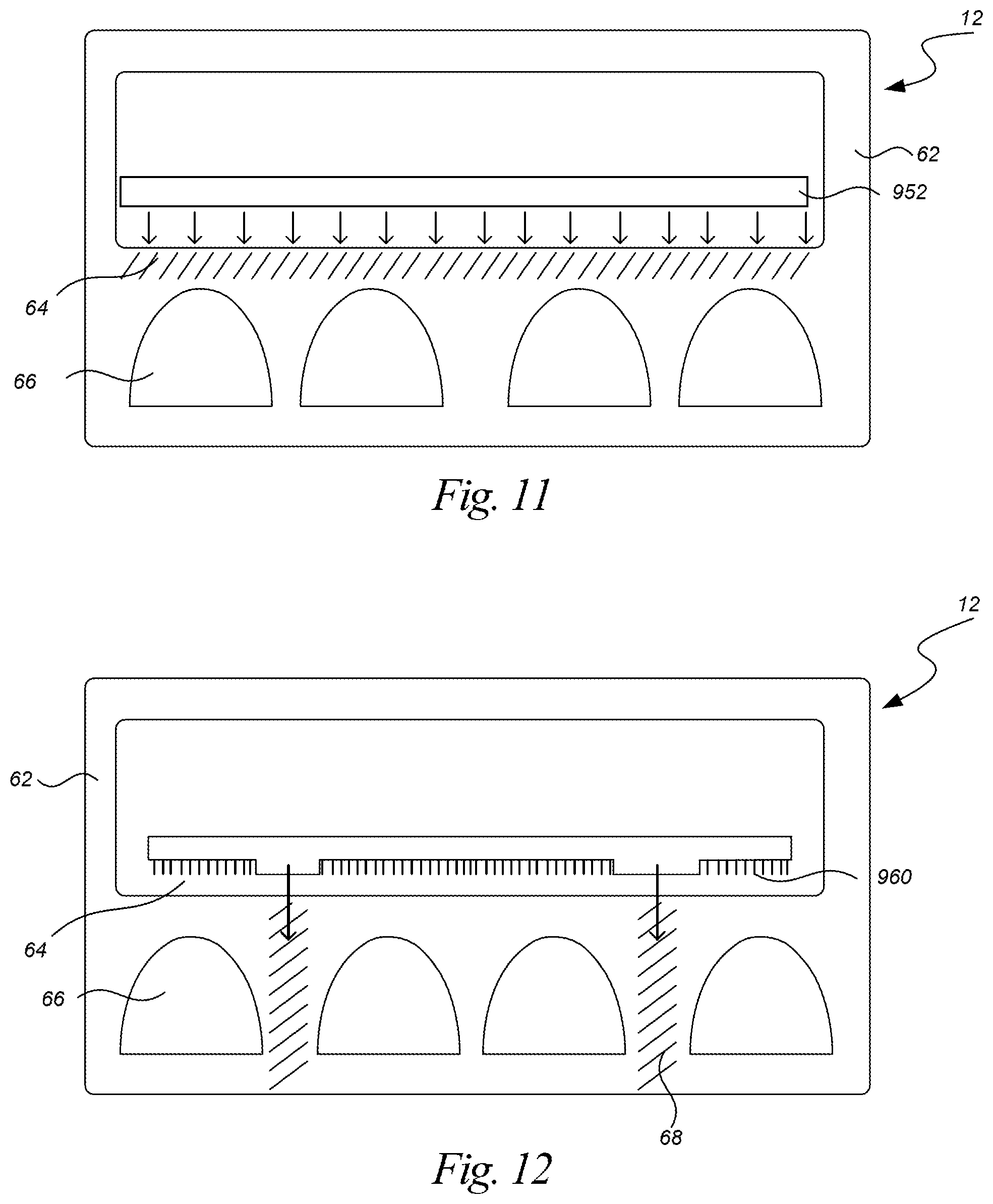
D00013
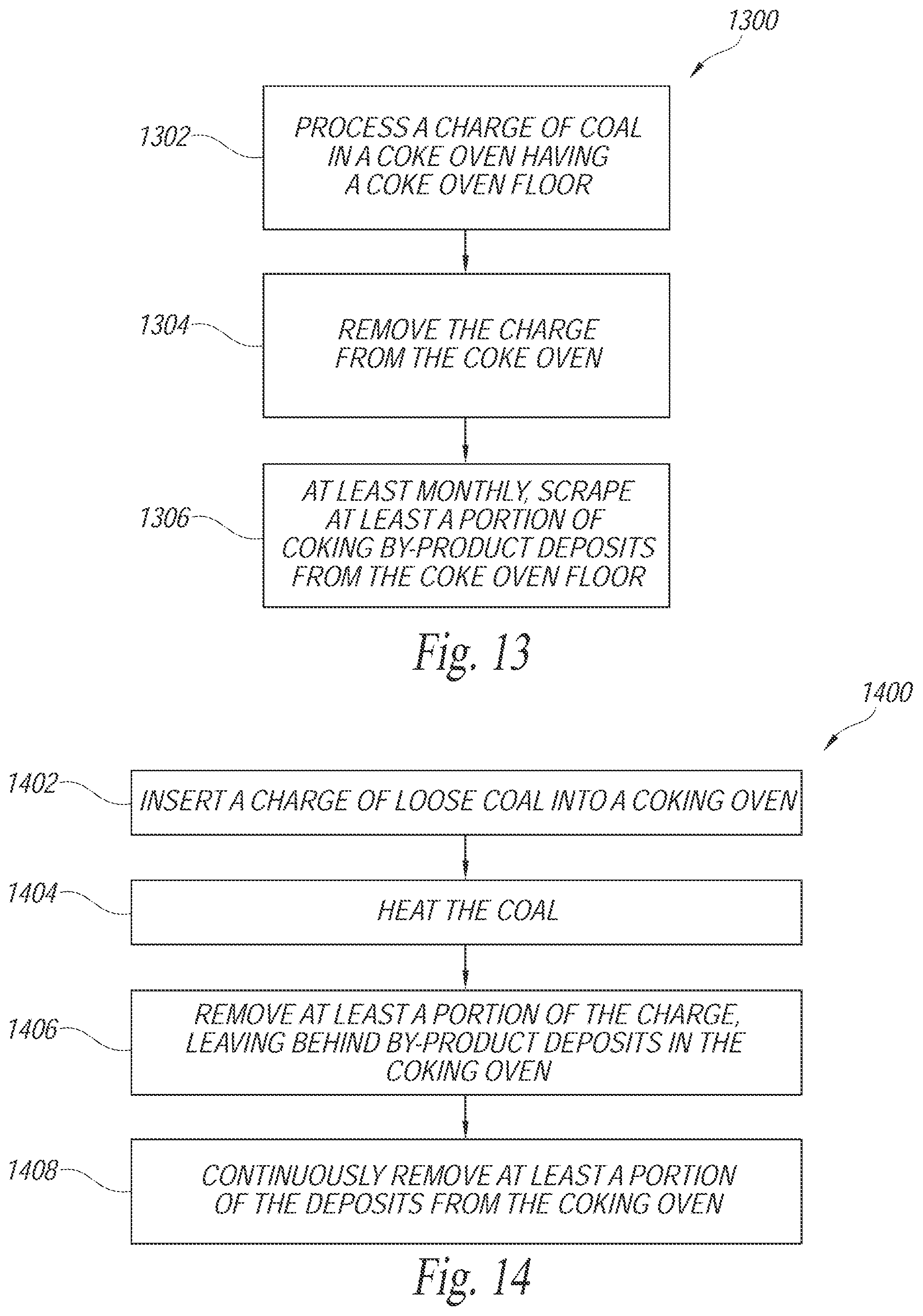
XML
uspto.report is an independent third-party trademark research tool that is not affiliated, endorsed, or sponsored by the United States Patent and Trademark Office (USPTO) or any other governmental organization. The information provided by uspto.report is based on publicly available data at the time of writing and is intended for informational purposes only.
While we strive to provide accurate and up-to-date information, we do not guarantee the accuracy, completeness, reliability, or suitability of the information displayed on this site. The use of this site is at your own risk. Any reliance you place on such information is therefore strictly at your own risk.
All official trademark data, including owner information, should be verified by visiting the official USPTO website at www.uspto.gov. This site is not intended to replace professional legal advice and should not be used as a substitute for consulting with a legal professional who is knowledgeable about trademark law.