Method for producing a mechanical locking system for panels
Josefsson , et al. November 17, 2
U.S. patent number 10,837,181 [Application Number 15/379,957] was granted by the patent office on 2020-11-17 for method for producing a mechanical locking system for panels. This patent grant is currently assigned to VALINGE INNOVATION AB. The grantee listed for this patent is VALINGE INNOVATION AB. Invention is credited to Christian Boo, Per Josefsson.


| United States Patent | 10,837,181 |
| Josefsson , et al. | November 17, 2020 |
Method for producing a mechanical locking system for panels
Abstract
A method for producing a mechanical locking system for a first panel and a second panel. The method includes providing a tongue, including a first locking surface, at a first edge of the first panel, forming a tongue groove, including a second locking surface, at a second edge of the second panel, the first locking surface and second locking surface are configured to cooperate for locking the first edge to the second edge in a first direction, providing a first guiding surface at the first edge and a second guiding surface at the second edge, wherein the first guiding surface cooperates with the second guiding surface during an assembling of the first edge and the second edge, and working of the first guiding surface and/or the second guiding surface to reduce the coefficient of friction between the first guiding surface and the second guiding surface and/or a surface roughness.
| Inventors: | Josefsson; Per (Ramlosa, SE), Boo; Christian (Kagerod, SE) | ||||||||||
|---|---|---|---|---|---|---|---|---|---|---|---|
| Applicant: |
|
||||||||||
| Assignee: | VALINGE INNOVATION AB (Viken,
SE) |
||||||||||
| Family ID: | 59057106 | ||||||||||
| Appl. No.: | 15/379,957 | ||||||||||
| Filed: | December 15, 2016 |
Prior Publication Data
| Document Identifier | Publication Date | |
|---|---|---|
| US 20170175400 A1 | Jun 22, 2017 | |
Foreign Application Priority Data
| Dec 17, 2015 [SE] | 1551670 | |||
| Current U.S. Class: | 1/1 |
| Current CPC Class: | E04F 15/02038 (20130101); E04F 15/102 (20130101); E04F 15/105 (20130101); E04F 15/02005 (20130101); E04F 13/0894 (20130101); E04F 2201/0535 (20130101); E04F 2201/0138 (20130101); E04F 2201/0547 (20130101); E04F 2201/043 (20130101); E04F 2201/023 (20130101); E04F 2201/042 (20130101); E04F 2201/0588 (20130101); E04F 2201/0146 (20130101) |
| Current International Class: | E04F 15/02 (20060101); E04F 15/10 (20060101); E04F 13/08 (20060101) |
| Field of Search: | ;29/897.32 |
References Cited [Referenced By]
U.S. Patent Documents
| 1787027 | December 1930 | Wasleff |
| 3120083 | February 1964 | Dahlberg et al. |
| 3247638 | April 1966 | Gay et al. |
| 3538665 | November 1970 | Gohner |
| 3694983 | October 1972 | Couquet |
| 3720027 | March 1973 | Christensen |
| 3742669 | July 1973 | Mansfeld |
| 3760547 | September 1973 | Brenneman |
| 3857749 | December 1974 | Yoshida |
| 3919820 | November 1975 | Green |
| 4113399 | September 1978 | Hansen, Sr. et al. |
| 4172169 | October 1979 | Mawson et al. |
| 4176210 | November 1979 | Skinner |
| 4180615 | December 1979 | Bettoli |
| 4187131 | February 1980 | Shortway et al. |
| 4196554 | April 1980 | Anderson et al. |
| 4313866 | February 1982 | Renshaw |
| 4333987 | June 1982 | Kwart et al. |
| 4393187 | July 1983 | Boba et al. |
| 4423178 | December 1983 | Renshaw |
| 4426820 | January 1984 | Terbrack |
| 4489115 | December 1984 | Layman et al. |
| 4507188 | March 1985 | Chu |
| 4512131 | April 1985 | Laramore |
| 4599841 | July 1986 | Haid |
| 4614680 | September 1986 | Fry et al. |
| 4772500 | September 1988 | Stroppiana |
| 4785065 | November 1988 | Uhl et al. |
| 4807412 | February 1989 | Frederiksen |
| 5007222 | April 1991 | Raymond |
| 5112671 | May 1992 | Diamond et al. |
| 5148850 | September 1992 | Urbanick |
| 5162141 | November 1992 | Davey et al. |
| 5182892 | February 1993 | Chase |
| 5344700 | September 1994 | McGath et al. |
| 5380794 | January 1995 | Schaefer et al. |
| 5441677 | August 1995 | Phillips, Sr. |
| 5458953 | October 1995 | Wang et al. |
| 5465546 | November 1995 | Buse |
| 5548937 | August 1996 | Shimonohara |
| 5618602 | April 1997 | Nelson |
| 5630304 | May 1997 | Austin |
| 5670237 | September 1997 | Shultz et al. |
| 5694730 | December 1997 | Del Rincon et al. |
| 5797237 | August 1998 | Finkell, Jr. |
| 5950389 | September 1999 | Porter |
| 6006486 | December 1999 | Moriau et al. |
| 6052960 | April 2000 | Yonemura |
| 6065262 | May 2000 | Motta |
| 6101778 | August 2000 | Martensson |
| 6139945 | October 2000 | Krejchi et al. |
| 6173548 | January 2001 | Hamar et al. |
| 6182410 | February 2001 | Pervan |
| 6209278 | April 2001 | Tychsen |
| 6216409 | April 2001 | Roy et al. |
| 6233899 | May 2001 | Mellert et al. |
| 6291078 | September 2001 | Chen et al. |
| 6324809 | December 2001 | Nelson |
| 6332733 | December 2001 | Hamberger et al. |
| 6345481 | February 2002 | Nelson |
| 6363677 | April 2002 | Chen |
| 6455127 | September 2002 | Valtanen |
| 6490836 | December 2002 | Moriau et al. |
| 6505452 | January 2003 | Hannig |
| 6536178 | March 2003 | Palsson et al. |
| 6546691 | April 2003 | Leopolder |
| 6553724 | April 2003 | Bigler |
| 6558070 | May 2003 | Valtanen |
| 6617009 | September 2003 | Chen et al. |
| 6647690 | November 2003 | Martensson |
| 6672030 | January 2004 | Schulte |
| 6675545 | January 2004 | Chen et al. |
| 6729091 | May 2004 | Martensson |
| 6761008 | July 2004 | Chen et al. |
| 6763643 | July 2004 | Martensson |
| 6766622 | July 2004 | Theirs |
| 6769218 | August 2004 | Pervan |
| 6769219 | August 2004 | Schwitte et al. |
| 6772568 | August 2004 | Thiers |
| 6790512 | September 2004 | MacQueen et al. |
| 6804926 | October 2004 | Eisermann |
| 6851241 | February 2005 | Pervan |
| 6854235 | February 2005 | Martensson |
| 6862857 | March 2005 | Tychsen |
| 6865855 | March 2005 | Knauseder |
| 6874292 | April 2005 | Moriau |
| 6880307 | April 2005 | Schwitte |
| 6895881 | May 2005 | Whitaker |
| 6928779 | August 2005 | Moriau et al. |
| 6986934 | January 2006 | Chen et al. |
| 7051486 | May 2006 | Pervan |
| 7090430 | August 2006 | Fletcher |
| 7121058 | October 2006 | Palsson et al. |
| 7155871 | January 2007 | Stone et al. |
| 7169460 | January 2007 | Chen et al. |
| 7171791 | February 2007 | Pervan |
| 7211310 | May 2007 | Chen et al. |
| 7251916 | August 2007 | Konzelmann et al. |
| 7275350 | October 2007 | Pervan et al. |
| 7337588 | March 2008 | Moebus |
| 7377081 | May 2008 | Ruhdorfer |
| 7398625 | July 2008 | Pervan |
| 7419717 | September 2008 | Chen et al. |
| 7451578 | November 2008 | Hannig |
| 7454875 | November 2008 | Pervan |
| 7484337 | February 2009 | Hecht |
| 7552568 | June 2009 | Palsson et al. |
| 7568322 | August 2009 | Pervan et al. |
| 7584583 | September 2009 | Bergelin et al. |
| 7603826 | October 2009 | Moebus |
| 7607271 | October 2009 | Griffin et al. |
| 7614197 | November 2009 | Nelson |
| 7617645 | November 2009 | Moriau et al. |
| 7621094 | November 2009 | Moriau et al. |
| 7634886 | December 2009 | Moriau et al. |
| 7634887 | December 2009 | Moriau et al. |
| 7637066 | December 2009 | Moriau et al. |
| 7640708 | January 2010 | Moriau et al. |
| 7644555 | January 2010 | Moriau et al. |
| 7644557 | January 2010 | Moriau et al. |
| 7647743 | January 2010 | Moriau et al. |
| 7650728 | January 2010 | Moriau et al. |
| 7654054 | February 2010 | Moriau et al. |
| 7658048 | February 2010 | Moriau et al. |
| 7677001 | March 2010 | Pervan |
| 7678215 | March 2010 | Martin |
| 7716896 | May 2010 | Pervan |
| 7739849 | June 2010 | Pervan |
| 7763345 | July 2010 | Chen et al. |
| 7779597 | August 2010 | Thiers et al. |
| 7802415 | September 2010 | Pervan |
| 7841144 | November 2010 | Pervan |
| 7841150 | November 2010 | Pervan |
| 7856784 | December 2010 | Martensson |
| 7856789 | December 2010 | Eisermann |
| 7861482 | January 2011 | Pervan |
| 7866110 | January 2011 | Pervan |
| 7886497 | February 2011 | Pervan et al. |
| 7896571 | March 2011 | Hannig et al. |
| 7930862 | April 2011 | Bergelin et al. |
| 7958689 | June 2011 | Lei |
| 7980043 | July 2011 | Moebus |
| 7984600 | July 2011 | Alford et al. |
| 8006460 | August 2011 | Chen et al. |
| 8021741 | September 2011 | Chen et al. |
| 8028486 | October 2011 | Pervan |
| 8038363 | October 2011 | Hannig |
| 8042311 | October 2011 | Pervan et al. |
| 8071193 | December 2011 | Windmoller |
| 8091238 | January 2012 | Hannig et al. |
| 8099924 | January 2012 | Braun |
| 8112891 | February 2012 | Pervan |
| 8132384 | March 2012 | Hannig |
| 8166718 | May 2012 | Liu |
| 8191333 | June 2012 | Braun |
| 8196366 | June 2012 | Thiers |
| 8215078 | July 2012 | Pervan |
| 8234829 | August 2012 | Thiers et al. |
| 8245478 | August 2012 | Bergelin et al. |
| 8281549 | October 2012 | Du |
| 8293058 | October 2012 | Pervan et al. |
| 8353140 | January 2013 | Pervan et al. |
| 8356452 | January 2013 | Thiers et al. |
| 8365499 | February 2013 | Nilsson et al. |
| 8375672 | February 2013 | Hannig |
| 8375674 | February 2013 | Braun |
| 8480841 | July 2013 | Pervan et al. |
| 8484924 | July 2013 | Braun |
| 8490361 | July 2013 | Curry et al. |
| 8499521 | August 2013 | Pervan et al. |
| 8511031 | August 2013 | Bergelin et al. |
| 8544231 | October 2013 | Hannig |
| 8544232 | October 2013 | Wybo et al. |
| 8544234 | October 2013 | Pervan et al. |
| 8584423 | November 2013 | Pervan et al. |
| 8613826 | December 2013 | Pervan et al. |
| 8658274 | February 2014 | Chen et al. |
| 8707651 | April 2014 | Stockl |
| 8720149 | May 2014 | Bossuyt |
| 8726604 | May 2014 | Hannig |
| 8745952 | June 2014 | Perra et al. |
| 8756899 | June 2014 | Nilsson et al. |
| 8763340 | July 2014 | Pervan et al. |
| 8800150 | August 2014 | Pervan |
| 8806832 | August 2014 | Kell |
| 8833028 | September 2014 | Whispell et al. |
| 8834992 | September 2014 | Chen et al. |
| 8952078 | February 2015 | Gould |
| 8966853 | March 2015 | Hannig |
| 8978336 | March 2015 | Perra |
| 9103126 | August 2015 | Kell |
| 9212492 | December 2015 | Pervan et al. |
| 9217250 | December 2015 | Perra |
| 9222267 | December 2015 | Bergelin et al. |
| 9228360 | January 2016 | Schneider |
| 9249581 | February 2016 | Nilsson et al. |
| 9260870 | February 2016 | Vermeulen et al. |
| 9296191 | March 2016 | Pervan et al. |
| 9314936 | April 2016 | Pervan |
| 9371653 | June 2016 | Liu |
| 9410328 | August 2016 | Pervan |
| 9528278 | December 2016 | Cappelle |
| 9650792 | May 2017 | Ramachandra |
| 9695600 | July 2017 | Vandervoorde |
| 9695601 | July 2017 | Whispell et al. |
| 9695851 | July 2017 | Hannig |
| 9714515 | July 2017 | Pervan |
| 9745758 | August 2017 | Baert |
| 9765530 | September 2017 | Bergelin et al. |
| 9777487 | October 2017 | Pervan et al. |
| 9803374 | October 2017 | Pervan |
| 9816270 | November 2017 | Pervan |
| 9874035 | January 2018 | Wagner |
| 9885186 | February 2018 | Liu |
| 9885187 | February 2018 | Kell |
| 10000935 | June 2018 | Kell |
| 10047527 | August 2018 | Nilsson et al. |
| 10059084 | August 2018 | Lundblad et al. |
| 10113318 | October 2018 | Cappelle |
| 10137659 | November 2018 | Pervan |
| 10214917 | February 2019 | Pervan et al. |
| 10287777 | May 2019 | Boo et al. |
| 10301830 | May 2019 | Boo |
| 10316526 | June 2019 | Kell |
| 10344379 | July 2019 | Pervan |
| 10407919 | September 2019 | Boo |
| 10450760 | October 2019 | Bergelin et al. |
| 10486399 | November 2019 | Chen et al. |
| 10493731 | December 2019 | Lundblad et al. |
| 10526793 | January 2020 | Nilsson et al. |
| 10704269 | July 2020 | Whispell et al. |
| 2001/0021431 | September 2001 | Chen |
| 2002/0007606 | January 2002 | Kettler |
| 2002/0007608 | January 2002 | Pervan |
| 2002/0007609 | January 2002 | Pervan |
| 2002/0031646 | March 2002 | Chen |
| 2002/0069611 | June 2002 | Leopolder |
| 2002/0092263 | July 2002 | Schulte |
| 2002/0142135 | October 2002 | Chen et al. |
| 2002/0152707 | October 2002 | Martensson |
| 2002/0170258 | November 2002 | Schwitte et al. |
| 2002/0178674 | December 2002 | Pervan |
| 2002/0178681 | December 2002 | Zancai |
| 2002/0189183 | December 2002 | Ricciardelli |
| 2003/0009971 | January 2003 | Palmberg |
| 2003/0024199 | February 2003 | Pervan |
| 2003/0024200 | February 2003 | Moriau et al. |
| 2003/0037504 | February 2003 | Schwitte et al. |
| 2003/0041545 | March 2003 | Stanchfield |
| 2003/0101674 | June 2003 | Pervan et al. |
| 2003/0101681 | June 2003 | Tychsen |
| 2003/0110720 | June 2003 | Berard et al. |
| 2003/0180091 | September 2003 | Stridsman |
| 2003/0188504 | October 2003 | Eisermann |
| 2003/0196405 | October 2003 | Pervan |
| 2003/0224147 | December 2003 | Maine et al. |
| 2004/0031225 | February 2004 | Fowler |
| 2004/0031227 | February 2004 | Knauseder |
| 2004/0060255 | April 2004 | Knauseder |
| 2004/0068954 | April 2004 | Martensson |
| 2004/0128934 | July 2004 | Hecht |
| 2004/0137180 | July 2004 | Sjoberg et al. |
| 2004/0139678 | July 2004 | Pervan |
| 2004/0177584 | September 2004 | Pervan |
| 2004/0182036 | September 2004 | Sjoberg et al. |
| 2004/0206036 | October 2004 | Pervan |
| 2004/0211143 | October 2004 | Hanning |
| 2004/0211144 | October 2004 | Stanchfield |
| 2004/0219339 | November 2004 | Dempsey et al. |
| 2004/0241374 | December 2004 | Thiers |
| 2004/0255538 | December 2004 | Ruhdorfer |
| 2004/0255541 | December 2004 | Thiers et al. |
| 2004/0261348 | December 2004 | Vulin |
| 2005/0003160 | January 2005 | Chen et al. |
| 2005/0028474 | February 2005 | Kim |
| 2005/0112320 | May 2005 | Wright |
| 2005/0138881 | June 2005 | Pervan |
| 2005/0144881 | July 2005 | Tate et al. |
| 2005/0166514 | August 2005 | Pervan |
| 2005/0176321 | August 2005 | Crette et al. |
| 2005/0193677 | September 2005 | Vogel |
| 2005/0208255 | September 2005 | Pervan |
| 2005/0210810 | September 2005 | Pervan |
| 2005/0221073 | October 2005 | Liou |
| 2005/0235593 | October 2005 | Hecht |
| 2005/0247000 | November 2005 | Zhu |
| 2005/0250921 | November 2005 | Qiu et al. |
| 2005/0252130 | November 2005 | Martensson |
| 2005/0268570 | December 2005 | Pervan |
| 2006/0010820 | January 2006 | Schwitte |
| 2006/0032168 | February 2006 | Thiers et al. |
| 2006/0032175 | February 2006 | Chen et al. |
| 2006/0053724 | March 2006 | Braun et al. |
| 2006/0070333 | April 2006 | Pervan |
| 2006/0101769 | May 2006 | Pervan et al. |
| 2006/0154015 | July 2006 | Miller et al. |
| 2006/0156666 | July 2006 | Caufield |
| 2006/0174974 | August 2006 | Brannstrom et al. |
| 2006/0225377 | October 2006 | Moriau et al. |
| 2006/0236642 | October 2006 | Pervan |
| 2006/0248830 | November 2006 | Moriau et al. |
| 2006/0248831 | November 2006 | Moriau et al. |
| 2006/0260252 | November 2006 | Brice |
| 2006/0260254 | November 2006 | Pervan |
| 2007/0006543 | January 2007 | Engstrom |
| 2007/0011981 | January 2007 | Eiserman |
| 2007/0022694 | February 2007 | Chen et al. |
| 2007/0028547 | February 2007 | Grafenauer et al. |
| 2007/0094986 | May 2007 | Moriau et al. |
| 2007/0094987 | May 2007 | Moriau et al. |
| 2007/0130872 | June 2007 | Goodwin |
| 2007/0151189 | July 2007 | Yang |
| 2007/0151191 | July 2007 | August |
| 2007/0154840 | July 2007 | Thies et al. |
| 2007/0175148 | August 2007 | Bergelin |
| 2007/0175156 | August 2007 | Pervan et al. |
| 2007/0184230 | August 2007 | Verrue et al. |
| 2007/0193178 | August 2007 | Groeke et al. |
| 2007/0196624 | August 2007 | Chen et al. |
| 2007/0218252 | September 2007 | Donald |
| 2007/0275207 | November 2007 | Higgins et al. |
| 2008/0000182 | January 2008 | Pervan |
| 2008/0000183 | January 2008 | Bergelin et al. |
| 2008/0000186 | January 2008 | Pervan et al. |
| 2008/0000188 | January 2008 | Pervan |
| 2008/0010931 | January 2008 | Pervan et al. |
| 2008/0010937 | January 2008 | Pervan |
| 2008/0028707 | February 2008 | Pervan |
| 2008/0028713 | February 2008 | Pervan |
| 2008/0029490 | February 2008 | Martin et al. |
| 2008/0034701 | February 2008 | Pervan |
| 2008/0034708 | February 2008 | Pervan |
| 2008/0041007 | February 2008 | Pervan |
| 2008/0053028 | March 2008 | Moriau et al. |
| 2008/0060309 | March 2008 | Moriau et al. |
| 2008/0060310 | March 2008 | Moriau et al. |
| 2008/0092473 | April 2008 | Heyns |
| 2008/0104921 | May 2008 | Pervan et al. |
| 2008/0110125 | May 2008 | Pervan |
| 2008/0133560 | June 2008 | Windmoller |
| 2008/0134607 | June 2008 | Pervan |
| 2008/0134613 | June 2008 | Pervan |
| 2008/0134614 | June 2008 | Pervan |
| 2008/0138560 | June 2008 | Windmoller |
| 2008/0141610 | June 2008 | Thiers |
| 2008/0148674 | June 2008 | Thiers et al. |
| 2008/0153609 | June 2008 | Kotler |
| 2008/0172971 | July 2008 | Pervan |
| 2008/0184646 | August 2008 | Alford |
| 2008/0241440 | October 2008 | Bauer |
| 2008/0256890 | October 2008 | Pervan |
| 2008/0311355 | December 2008 | Chen et al. |
| 2009/0031662 | February 2009 | Chen et al. |
| 2009/0038253 | February 2009 | Martensson |
| 2009/0049787 | February 2009 | Hannig |
| 2009/0110888 | April 2009 | Wuest et al. |
| 2009/0133353 | May 2009 | Pervan et al. |
| 2009/0151290 | June 2009 | Liu |
| 2009/0159156 | June 2009 | Walker |
| 2009/0186710 | July 2009 | Joseph |
| 2009/0193748 | August 2009 | Boo |
| 2009/0217611 | September 2009 | Schrader |
| 2009/0223162 | September 2009 | Chen et al. |
| 2009/0226662 | September 2009 | Dyczko-Riglin et al. |
| 2009/0235604 | September 2009 | Cheng et al. |
| 2009/0249733 | October 2009 | Moebus |
| 2009/0260313 | October 2009 | Segaert |
| 2009/0272058 | November 2009 | Duselis et al. |
| 2009/0320402 | December 2009 | Schacht et al. |
| 2010/0011695 | January 2010 | Cheng |
| 2010/0018149 | January 2010 | Thiers |
| 2010/0031594 | February 2010 | Liu |
| 2010/0043333 | February 2010 | Hannig et al. |
| 2010/0058702 | March 2010 | Lei |
| 2010/0260962 | October 2010 | Chen et al. |
| 2010/0293879 | November 2010 | Pervan et al. |
| 2010/0300029 | December 2010 | Braun et al. |
| 2010/0319293 | December 2010 | Dammers et al. |
| 2011/0001420 | January 2011 | Tchakarov et al. |
| 2011/0008567 | January 2011 | Weeks et al. |
| 2011/0030303 | February 2011 | Pervan et al. |
| 2011/0041996 | February 2011 | Pervan |
| 2011/0056167 | March 2011 | Nilsson et al. |
| 2011/0094178 | April 2011 | Braun |
| 2011/0131901 | June 2011 | Pervan et al. |
| 2011/0131909 | June 2011 | Hannig |
| 2011/0138722 | June 2011 | Hannig |
| 2011/0146177 | June 2011 | Hannig |
| 2011/0154763 | June 2011 | Bergelin et al. |
| 2011/0167744 | July 2011 | Whispell |
| 2011/0173914 | July 2011 | Engstrom |
| 2011/0247285 | October 2011 | Wybo |
| 2011/0247748 | October 2011 | Pervan et al. |
| 2011/0258959 | October 2011 | Braun |
| 2011/0296780 | December 2011 | Windmoller |
| 2012/0003439 | January 2012 | Chen et al. |
| 2012/0017534 | January 2012 | Oh |
| 2012/0040149 | February 2012 | Chen et al. |
| 2012/0066996 | March 2012 | Konstanczak |
| 2012/0067461 | March 2012 | Braun |
| 2012/0124932 | May 2012 | Schulte et al. |
| 2012/0137617 | June 2012 | Pervan |
| 2012/0174519 | July 2012 | Schulte |
| 2012/0174521 | July 2012 | Schulte |
| 2012/0180416 | July 2012 | Perra et al. |
| 2012/0192521 | August 2012 | Schulte |
| 2012/0216472 | August 2012 | Martensson |
| 2012/0266555 | October 2012 | Cappelle |
| 2012/0276369 | November 2012 | Jing et al. |
| 2012/0279154 | November 2012 | Bergelin et al. |
| 2012/0304581 | December 2012 | Kim |
| 2013/0008118 | January 2013 | Baert |
| 2013/0014890 | January 2013 | Pervan et al. |
| 2013/0025964 | January 2013 | Ramachandra |
| 2013/0042563 | February 2013 | Pervan et al. |
| 2013/0042565 | February 2013 | Pervan et al. |
| 2013/0047536 | February 2013 | Pervan |
| 2013/0097959 | April 2013 | Michel |
| 2013/0111758 | May 2013 | Nilsson et al. |
| 2013/0152492 | June 2013 | Whitaker |
| 2013/0160391 | June 2013 | Pervan et al. |
| 2013/0174507 | July 2013 | Oehrlein |
| 2013/0212971 | August 2013 | Cordeiro |
| 2013/0243996 | September 2013 | Hannig |
| 2013/0269863 | October 2013 | Pervan et al. |
| 2013/0283719 | October 2013 | Dohring |
| 2013/0298487 | November 2013 | Bergelin et al. |
| 2013/0305650 | November 2013 | Liu |
| 2013/0309441 | November 2013 | Hannig |
| 2013/0333182 | December 2013 | Pervan et al. |
| 2014/0007539 | January 2014 | Pervan et al. |
| 2014/0033633 | February 2014 | Kell |
| 2014/0033635 | February 2014 | Pervan et al. |
| 2014/0069043 | March 2014 | Pervan |
| 2014/0069044 | March 2014 | Wallin |
| 2014/0115994 | May 2014 | Pervan |
| 2014/0186104 | July 2014 | Hamberger |
| 2014/0215946 | August 2014 | Roy et al. |
| 2014/0237924 | August 2014 | Nilsson et al. |
| 2014/0283466 | September 2014 | Boo |
| 2014/0283477 | September 2014 | Hannig |
| 2014/0290173 | October 2014 | Hamberger |
| 2014/0318061 | October 2014 | Pervan |
| 2014/0325930 | November 2014 | Schneider |
| 2014/0352248 | December 2014 | Whispell et al. |
| 2014/0356594 | December 2014 | Chen et al. |
| 2014/0366476 | December 2014 | Pervan |
| 2014/0366477 | December 2014 | Kell |
| 2015/0114552 | April 2015 | Cernohous |
| 2015/0225964 | August 2015 | Chen et al. |
| 2015/0252573 | September 2015 | Devos |
| 2015/0330088 | November 2015 | Derelov |
| 2015/0368910 | December 2015 | Kell |
| 2016/0016390 | January 2016 | Lundblad et al. |
| 2016/0016391 | January 2016 | Lundblad et al. |
| 2016/0047129 | February 2016 | Bowers |
| 2016/0052245 | February 2016 | Chen et al. |
| 2016/0069089 | March 2016 | Bergelin et al. |
| 2016/0076260 | March 2016 | Pervan et al. |
| 2016/0108624 | April 2016 | Nilsson et al. |
| 2016/0115695 | April 2016 | Devos |
| 2016/0138274 | May 2016 | Anspach et al. |
| 2016/0186318 | June 2016 | Pervan et al. |
| 2016/0194883 | July 2016 | Pervan |
| 2016/0194885 | July 2016 | Whispell et al. |
| 2016/0201324 | July 2016 | Hakansson et al. |
| 2016/0265234 | September 2016 | Pervan |
| 2016/0333595 | November 2016 | Cappelle |
| 2016/0375674 | December 2016 | Schulte |
| 2017/0030088 | February 2017 | Simoens |
| 2017/0037642 | February 2017 | Boo |
| 2017/0037645 | February 2017 | Pervan |
| 2017/0241136 | August 2017 | Kell |
| 2017/0350140 | December 2017 | Bergelin et al. |
| 2017/0362834 | December 2017 | Pervan et al. |
| 2017/0370109 | December 2017 | Devos |
| 2018/0010342 | January 2018 | Van Hooydonck |
| 2018/0094441 | April 2018 | Boo et al. |
| 2018/0313093 | November 2018 | Nilsson et al. |
| 2019/0017278 | January 2019 | De Rick et al. |
| 2019/0091977 | March 2019 | Lundblad et al. |
| 2019/0136545 | May 2019 | De Rick et al. |
| 2019/0211569 | July 2019 | Boo et al. |
| 2019/0249444 | August 2019 | Kell |
| 2019/0277041 | September 2019 | Pervan et al. |
| 2019/0394314 | December 2019 | Pervan et al. |
| 2020/0056379 | February 2020 | Boo |
| 2020/0063441 | February 2020 | Boo |
| 2020/0180282 | June 2020 | Lundblad et al. |
| 2020/0208409 | July 2020 | Kell |
| 2 252 791 | May 1999 | CA | |||
| 1270263 | Oct 2000 | CN | |||
| 101492950 | Jul 2009 | CN | |||
| 2 251 762 | May 1974 | DE | |||
| 198 54 475 | Jul 1999 | DE | |||
| 202 07 844 | Aug 2002 | DE | |||
| 20 2005 004 537 | Jun 2005 | DE | |||
| 198 54 475 | Jun 2006 | DE | |||
| 10 2005 061 099 | Mar 2007 | DE | |||
| 10 2006 024 184 | Nov 2007 | DE | |||
| 10 2006 058 655 | Jun 2008 | DE | |||
| 10 2006 058 655 | Jun 2008 | DE | |||
| 20 2008 011 589 | Nov 2008 | DE | |||
| 20 2008 012 001 | Nov 2008 | DE | |||
| 20 2004 021 867 | Dec 2011 | DE | |||
| 202004021867 | Dec 2011 | DE | |||
| 20 2016 102 034 | May 2016 | DE | |||
| 1 045 083 | Oct 2000 | EP | |||
| 1 165 906 | Jan 2002 | EP | |||
| 1 165 906 | Aug 2002 | EP | |||
| 1 045 083 | Oct 2002 | EP | |||
| 1 308 577 | May 2003 | EP | |||
| 1 350 904 | Oct 2003 | EP | |||
| 1 420 125 | May 2004 | EP | |||
| 1 585 875 | Oct 2005 | EP | |||
| 1 585 875 | Oct 2006 | EP | |||
| 1 570 143 | May 2007 | EP | |||
| 1 938 963 | Jul 2008 | EP | |||
| 2 009 197 | Dec 2008 | EP | |||
| 2 339 092 | Jun 2011 | EP | |||
| 2 516 768 | Jun 2011 | EP | |||
| 2 615 221 | Jul 2013 | EP | |||
| 1 293 043 | Apr 1961 | FR | |||
| 1 430 423 | Mar 1976 | GB | |||
| 60-255843 | Dec 1985 | JP | |||
| 7-180333 | Jul 1995 | JP | |||
| H07-300979 | Nov 1995 | JP | |||
| H08-74405 | Mar 1996 | JP | |||
| 3363976 | Jan 2003 | JP | |||
| 1996-0005785 | Jul 1996 | KR | |||
| 10-2008-0096189 | Oct 2008 | KR | |||
| 10-0870496 | Nov 2008 | KR | |||
| 0000785 | Sep 2001 | SE | |||
| WO 94/26999 | Nov 1994 | WO | |||
| WO 96/27721 | Sep 1996 | WO | |||
| WO 98/58142 | Dec 1998 | WO | |||
| WO 00/47841 | Aug 2000 | WO | |||
| WO 00/66856 | Nov 2000 | WO | |||
| WO 01/02669 | Jan 2001 | WO | |||
| WO 01/02670 | Jan 2001 | WO | |||
| WO 01/02671 | Jan 2001 | WO | |||
| WO 01/44669 | Jun 2001 | WO | |||
| WO 01/44669 | Jun 2001 | WO | |||
| WO 01/48331 | Jul 2001 | WO | |||
| WO 01/48332 | Jul 2001 | WO | |||
| WO 01/51732 | Jul 2001 | WO | |||
| WO 01/51733 | Jul 2001 | WO | |||
| WO 01/66877 | Sep 2001 | WO | |||
| WO 01/75247 | Oct 2001 | WO | |||
| WO 01/77461 | Oct 2001 | WO | |||
| WO 01/88306 | Nov 2001 | WO | |||
| WO 01/98604 | Dec 2001 | WO | |||
| WO 02/103135 | Dec 2002 | WO | |||
| WO 03/012224 | Feb 2003 | WO | |||
| WO 03/016654 | Feb 2003 | WO | |||
| WO 03/044303 | May 2003 | WO | |||
| WO 2004/011740 | Feb 2004 | WO | |||
| WO 2004/016877 | Feb 2004 | WO | |||
| WO 2004/050780 | Jun 2004 | WO | |||
| WO 2004/085765 | Oct 2004 | WO | |||
| WO 2005/068747 | Jul 2005 | WO | |||
| WO 2005/088029 | Sep 2005 | WO | |||
| WO 2005/098163 | Oct 2005 | WO | |||
| WO 2006/032378 | Mar 2006 | WO | |||
| WO 2006/043893 | Apr 2006 | WO | |||
| WO-2006104436 | Oct 2006 | WO | |||
| WO 2006/123988 | Nov 2006 | WO | |||
| WO 2006/133690 | Dec 2006 | WO | |||
| WO 2007/015669 | Feb 2007 | WO | |||
| WO 2007/015669 | Feb 2007 | WO | |||
| WO 2007/016978 | Feb 2007 | WO | |||
| WO 2007/020088 | Feb 2007 | WO | |||
| WO 2007/079845 | Jul 2007 | WO | |||
| WO 2007/118352 | Oct 2007 | WO | |||
| WO 2008/008016 | Jan 2008 | WO | |||
| WO 2008/008824 | Jan 2008 | WO | |||
| WO 2008/068245 | Jun 2008 | WO | |||
| WO 2008/116623 | Oct 2008 | WO | |||
| WO 2008/133377 | Nov 2008 | WO | |||
| WO 2009/061279 | May 2009 | WO | |||
| WO 2009/071822 | Jun 2009 | WO | |||
| WO 2009/071822 | Jun 2009 | WO | |||
| WO 2010/015516 | Feb 2010 | WO | |||
| WO 2010/015516 | Feb 2010 | WO | |||
| WO 2010/023042 | Mar 2010 | WO | |||
| WO 2010/028901 | Mar 2010 | WO | |||
| WO 2010/072357 | Jul 2010 | WO | |||
| WO 2010/072357 | Jul 2010 | WO | |||
| WO 2010/081532 | Jul 2010 | WO | |||
| WO 2010/086084 | Aug 2010 | WO | |||
| WO 2010/114236 | Oct 2010 | WO | |||
| WO 2010/128043 | Nov 2010 | WO | |||
| WO 2011/012104 | Feb 2011 | WO | |||
| WO 2011/028171 | Mar 2011 | WO | |||
| WO 2011/032540 | Mar 2011 | WO | |||
| WO 2011/038709 | Apr 2011 | WO | |||
| WO 2011/077311 | Jun 2011 | WO | |||
| WO 2012/084604 | Jun 2012 | WO | |||
| WO 2012/101171 | Aug 2012 | WO | |||
| WO 2012/126046 | Sep 2012 | WO | |||
| WO 2012/136021 | Oct 2012 | WO | |||
| WO 2013/017575 | Feb 2013 | WO | |||
| WO 2013/026559 | Feb 2013 | WO | |||
| WO 2013/044758 | Apr 2013 | WO | |||
| WO 2013/092270 | Jun 2013 | WO | |||
| WO 2013/151493 | Oct 2013 | WO | |||
| WO 2014/007738 | Jan 2014 | WO | |||
| WO 2014/043756 | Mar 2014 | WO | |||
| WO 2014/182215 | Nov 2014 | WO | |||
| WO 2014/209213 | Dec 2014 | WO | |||
| WO 2015/078443 | Jun 2015 | WO | |||
| WO 2015/104680 | Jul 2015 | WO | |||
| WO 2015/174914 | Nov 2015 | WO | |||
| WO 2016/029255 | Mar 2016 | WO | |||
| WO-2017101910 | Jun 2017 | WO | |||
| WO 2017/115202 | Jul 2017 | WO | |||
| WO 2017/187298 | Nov 2017 | WO | |||
Other References
|
Machine Translation of DE202004021867 (Year: 2011). cited by examiner . Machine Translation of DE202004021867 (Year: 2012). cited by examiner . Machine Translation of WO2017101910 (Year: 2016). cited by examiner . Lowe's, How to Install a Laminate Floor, YouTube video available for viewing at https://youtu.be/zhIXVHAejlk?t=3m52s, Oct. 2008 (last accessed Feb. 15, 2018). cited by applicant . U.S. Appl. No. 14/224,628, Christian Boo, filed Mar. 25, 2014. (Cited herein as US Patent Application Publication No. 2014/0283466 A1 of Sep. 25, 2014). cited by applicant . U.S. Appl. No. 14/463,008, John M. Whispell, filed Aug. 19, 2014 (Cited herein as US Patent Application Publication No. 2014/0352248 A1 of Dec. 4, 2014). cited by applicant . U.S. Appl. No. 14/982,608, Mats Nilsson, filed Dec. 29, 2015 (Cited herein as US Patent Application Publication No. 2016/0108624 A1 of Apr. 21, 2016). cited by applicant . U.S. Appl. No. 15/067,999, Darko Pervan, filed Mar. 11, 2016 (Cited herein as US Patent Application Publication No. 2016/0194883 A1 of Jul. 7, 2016). cited by applicant . U.S. Appl. No. 15/072,829, John M. Whispell, filed Mar. 17, 2016 (Cited herein as US Patent Application Publication No. 2016/0194885 A1 of Jul. 7, 2016). cited by applicant . U.S. Appl. No. 15/333,630, Christian Boo, filed Oct. 15, 2016 (Cited herein as US Patent Application Publication No. 2017/0037642 A1 of Feb. 9, 2017). cited by applicant . U.S. Appl. No. 15/404,617, Christian Boo, filed Jan. 12, 2017. cited by applicant . U.S. Appl. No. 15/404,617, Boo. cited by applicant . Pervan, Darko (Author)/Valinge Innovation, Technical Disclosure entitled "VA073a Zip Loc," Sep. 13, 2011, IP.com No. IPCOM0002108690, IP.com PriorArtDatabase, 36 pages. cited by applicant . Boo, Christian, U.S. Appl. No. 15/404,617 entitled "Set of Panels," filed in the U.S. Patent and Trademark Office on Jan. 12, 2017. cited by applicant . U.S. Appl. No. 15/507,602, Richard William Kell, filed Feb. 28, 2017 (Cited herein as US Patent Application Publication No. 2017/0241136 A1 of Aug. 24, 2017). cited by applicant . U.S. Appl. No. 16/027,465, Mats Nilsson and Per Nygren, filed Jul. 5, 2018 (Cited herein as US Patent Application Publication No. 2018/0313093 A1 of Nov. 1, 2018). cited by applicant . International Search Report and Written Opinion issued in PCT/SE2016/051272, dated Feb. 1, 2017, Patent-och registreringsverket, Stockholm, SE, 12 pages. cited by applicant . U.S. Appl. No. 16/220,748, Christian Boo, Marcus Nilsson Stahl and Anders Nilsson, filed Dec. 14, 2018. cited by applicant . U.S. Appl. No. 16/220,748, Boo, et al. cited by applicant . Boo, Christian, et al., U.S. Appl. No. 16/220,748, entitled "Set of Panels," filed in the U.S. Patent and Trademark Office on Dec. 14, 2018. cited by applicant . U.S. Appl. No. 16/366,173, Boo. cited by applicant . U.S. Appl. No. 16/392,931, Kell. cited by applicant . Boo, Christian, U.S. Appl. No. 16/366,173 entitled "Set of Panels," filed in the U.S. Patent and Trademark Office on Mar. 27, 2019. cited by applicant . Kell, Richard William, U.S. Appl. No. 16/392,931, entitled "Vertical Joint System for a Surface Covering Panel," filed in the U.S. Patent and Trademark Office on Apr. 24, 2019. cited by applicant . U.S. Appl. No. 16/528,992, Christian Boo, filed Aug. 1, 2019. cited by applicant . U.S. Appl. No. 16/528,992, Boo. cited by applicant . Extended European Search Report dated Jul. 1, 2019 in EP 16876159.1, European Patent Office, Munich, DE, 10 pages. cited by applicant . Boo, Christian, U.S. Appl. No. 16/528,992 entitled "*Floorboards Provided with a Mechanical Locking System," filed in the U.S. Patent and Trademark Office on Aug. 1, 2019. cited by applicant . U.S. Appl. No. 16/699,297, Richard William Kell, filed Nov. 29, 2019. cited by applicant . U.S. Appl. No. 16/713,431, Mats Nilsson and Per Nygren, filed Dec. 13, 2019. cited by applicant . U.S. Appl. No. 16/699,297, Kell. cited by applicant . U.S. Appl. No. 16/713,431, Nilsson et al. cited by applicant . Kell, Richard William, U.S. Appl. No. 16/699,297 entitled "Vertical Joint System for a Surface Covering Panel," filed in the U.S. Patent and Trademark Office on Nov. 29, 2019. cited by applicant . Nilsson, Mats, et al., U.S. Appl. No. 16/713,431 entitled "Resilient Floor," filed in the U.S. Patent and Trademark Office on Dec. 13, 2019. cited by applicant . U.S. Appl. No. 16/887,559, John M Whispell and Hao A Chen, filed May 29, 2020. cited by applicant . U.S. Appl. No. 16/887,559, Whispell et al. cited by applicant . Whispell, John M., et al., U.S. Appl. No. 16/887,559 entitled "Floor Covering with Interlocking Design," filed in the U.S. Patent and Trademark Office on May 29, 2020. cited by applicant. |
Primary Examiner: Cigna; Jacob J
Assistant Examiner: Hotchkiss; Michael W
Attorney, Agent or Firm: Buchanan Ingersoll & Rooney P.C.
Claims
The invention claimed is:
1. A method for producing a mechanical locking system for a first panel and a second panel, wherein the first and second panels comprise a core material comprising a thermoplastic material, wherein the method comprises: providing a tongue, comprising a first locking surface, at a first edge of the first panel; forming a tongue groove, comprising a second locking surface, at a second edge of the second panel, said first locking surface and second locking surface are configured to cooperate for locking the first edge to the second edge in a first direction; providing a first guiding surface at the first edge and a second guiding surface at the second edge, wherein the mechanical locking system is configured such that first guiding surface cooperates with the second guiding surface during an assembling of the first edge and the second edge; and working of the first guiding surface and/or the second guiding surface, to reduce a surface roughness of the worked guiding surface(s), wherein the working is performed by a fixed tool; and working, with the fixed tool, of an adjacent surface which is adjacent to the second guiding surface, while working the first guiding surface and/or the second guiding surface with the fixed tool.
2. The method as claimed in claim 1, comprising working the second guiding surface, wherein the method for forming the second locking surface is different from the method for working of the second guiding surface.
3. The method as claimed in claim 1, comprising working the first guiding surface, wherein a method for forming the first locking surface is different from the method for working of the first guiding surface.
4. The method as claimed in claim 1, wherein the working of the first guiding surface and/or the second guiding surface is a polishing, a sanding, a grinding and/or a pressing.
5. The method as claimed in claim 1, wherein the core material comprises a filler and/or a reinforcement material.
6. The method as claimed in claim 1, wherein the working of the first guiding surface or the second guiding surface is made before the forming of the tongue groove.
7. The method as claimed in claim 1, wherein the method comprises forming an insertion groove, at the first edge and arranging the tongue, in the insertion groove.
8. The method as claimed in claim 1, wherein the method comprises forming the tongue, at the first edge.
9. The method as claimed in claim 1, wherein one or more of the tongue, the tongue groove, the locking element and the locking groove are formed of a core material of the first and or the second panel.
10. The method as claimed in claim 1, wherein the working of the first guiding surface and/or the second guiding surface reduces the surface roughness value within the range of about 30% to about 50%.
11. The method as claimed in claim 1, wherein the working of the first guiding surface and/or the second guiding surface reduces the surface roughness to a value of less than about 2.5 Ra.
12. The method as claimed in claim 1, wherein the working of the first guiding surface and/or the second guiding surface decreases the surface roughness value at least 0.5 Ra.
13. The method as claimed in claim 1, wherein the working of the first guiding surface and/or the second guiding surface reduces the surface roughness value from about 3 Ra to about 2 Ra.
14. The method as claimed in claim 1, wherein the first and second panels are building panels or floor panels.
15. The method as claimed in claim 1, wherein the fixed tool is a sliding bar or a pressure shoe.
16. The method as claimed in claim 1, wherein the working of the first guiding surface and/or the second guiding surface is a sanding, a grinding and/or a pressing.
17. The method as claimed in claim 1, wherein the adjacent surface is at a non-zero angle relative to the second guiding surface.
18. The method as claimed in claim 1, wherein the method comprises: forming a locking element at the first edge or the second edge; and forming a locking groove at the other of the first edge or the second edge, wherein the locking element is configured to cooperate with the locking groove for locking the first edge to the second edge in a second direction which is perpendicular to the first direction.
19. The method as claimed in claim 18, wherein the tongue is formed at the locking element or the locking groove and the tongue groove is formed at the other of the locking element or locking groove.
20. The method as claimed in claim 1, wherein the fixed tool works the second guiding surface and the adjacent surface at the same time.
21. The method as claimed in claim 20, wherein the adjacent surface is at a non-zero angle relative to the second guiding surface.
Description
CROSS REFERENCE TO RELATED APPLICATIONS
The present application claims the benefit of Swedish application no. 1551670-1, filed on 17 Dec. 2015. The entire contents of Swedish application no. 1551670-1 are hereby expressly incorporated by reference in their entirety.
TECHNICAL FIELD
The present disclosure relates to floorboards provided with a mechanical locking system, and a method for producing a mechanical locking system at edges of floorboards.
BACKGROUND
Panels provided with a mechanical locking device are known in the art, as evidenced by WO2014/182215 (A1). The panels are, for some materials, difficult to assemble.
SUMMARY
One object of certain embodiments of the present invention to provide an improvement over the above described technique and the known art. A specific objective of certain embodiments is to improve assembling of panels, such as floor, building or furniture panels.
At least some of these and other objects and advantages that will be apparent from the description have been achieved by embodiments of a first aspect of the invention that includes a method for producing a mechanical locking system for a first panel and a second panel, such as building panels or floor panels, wherein the method comprises: providing a tongue, comprising a first locking surface, at a first edge of the first panel; forming a tongue groove, comprising a second locking surface, preferably by mechanical cutting, at a second edge of the second panel, said first locking surface and second locking surface are configured to cooperate for locking the first edge to the second edge in a first direction; providing a first guiding surface at the first edge and a second guiding surface at the second edge, wherein the mechanical locking system is configured such that first guiding surface cooperates with the second guiding surface during an assembling of the first edge and the second edge; and working of the first guiding surface and/or the second guiding surface to reduce a coefficient of friction and/or to reduce a surface roughness.
The mechanical locking system may be produced by mechanical cutting, such as milling, preferably in a milling line. Said working of the first guiding surface and/or the second guiding surface to reduce the coefficient of friction and/or surface roughness may be made in the milling line. The mechanical cutting may result in a guiding surface with a high friction coefficient and/or a coarse surface roughness. An assembling of the first panel and the second panel that comprise guiding surfaces with a high friction coefficient or a coarse surface roughness may be difficult. The assembling may be facilitated by said working of the first and/or the second guiding surface.
The method for forming the second locking surface may be different from the method for working of the second guiding surface.
The method for forming the first locking surface may be different from the method for working of the first guiding surface.
The working of the first guiding surface and/or the second guiding surface may be polishing, sanding, rolling, grinding and/or pressing by, e.g., a fixed tool, such as a sliding bar or pressure shoe. The fixed tool may be of metal, such as steel, and preferably comprises a surface of hard metal or diamond.
The working of the first guiding surface and/or the second guiding surface preferably reduces the surface roughness within the range of about 30% to about 50%, or about 30% to about 40%. Such a decrease of surface roughness may result in a considerable reduction of the coefficient of friction. This may have the effect that the assembling of first panel and the second panel changes from being difficult to easy, or for some embodiments from being impossible to easy.
The surface roughness value may be decreased from about 3 Ra to about 2 Ra. For example, the surface roughness may be decreased at least 0.5 Ra, such as at least 0.8 Ra, such as at least 1 Ra. For example, the surface roughness may be decreased to a value of less than about 2.5 Ra, such as less than 2.2 Ra, such as less than 2 Ra.
The first panel and the second panel may comprise a core material comprising a polymer material.
The polymer material may be one or more of the materials: Vinyls, such as polyvinyl chloride and polyvinyl butyral; Polyolefins, such as PE and PP; Polyesters, including polyethylene terephthalate (PET); Styrenics, such as polystyrene; Acrylics, such as PMMA; Co-polymers; Polymer blends;
The core material may comprise a filler and/or a reinforcement material.
The reinforcement material may be arranged as a reinforcement layer extending essentially parallel to an upper surface of the first panel and the second panel, respectively. Said reinforcement layer may increase the friction and may therefore be arranged such that an outer edge of the reinforcement layer is preferably at a non-guiding surface, such as a bottom surface of the tongue groove.
The filler material may be one or more of wood fibre, preferably as dust, or chalk.
The reinforcement material may be one or more of calcium silicate, e.g., wollastonite, or glass fiber.
The working of the of the first guiding surface and/or the second guiding surface may be made before the forming of the tongue groove. Applying a pressure after the forming of the tongue may deform the tongue groove and/or the first edge and/or the second edge.
The method may comprise forming an insertion groove, preferably by mechanical cutting, at the first edge and arranging the tongue, preferably a displaceable tongue, in the insertion groove.
The method may comprise forming the tongue, preferably by mechanical cutting, at the first edge.
The method may comprise: forming a locking element at the first edge or the second edge, preferably by mechanical cutting; and forming a locking groove at the other of the first edge or the second edge, preferably by mechanical cutting, wherein the locking element is configured to cooperate with the locking groove for locking the first edge to the second edge in a second direction which is perpendicular to the first direction.
The tongue may be formed at the locking element or the locking groove and the tongue groove may be formed at the other of the locking element or locking groove.
One or more of the tongue, the tongue groove, the locking element and the locking groove may be formed of a core material of the first and or the second panel.
The flexible tongue may be according to a flexible tongue described and shown in any one of WO2006/043893, WO2007/015669, or preferably FIGS. 8A-8B in WO2014/209213(A1). The entire disclosure of each of which is hereby expressly incorporated by reference herein.
The set of panels may be furniture panels.
The core may be provided with a decorative layer.
A second aspect of the invention includes a set comprising a first and a second panel produced by the method described above.
BRIEF DESCRIPTION OF THE DRAWINGS
Embodiments of the present invention will by way of example be described in more detail with reference to the appended schematic drawings, in which:
FIGS. 1A-1C show a first panel and a second panel according to an embodiment of the invention during an assembling.
FIGS. 2A-2B show a first panel and a second panel according to an embodiment of the invention during an assembling.
FIGS. 3A-3B show a first panel and a second panel according to an embodiment of the invention during an assembling.
FIGS. 4A-4B show a first panel and a second panel according to an embodiment of the invention during an assembling.
FIGS. 5A-5B show a first panel and a second panel according to an embodiment of the invention during an assembling.
FIGS. 6A-6B show a first panel and a second panel according to an embodiment of the invention during an assembling.
FIGS. 7A-7C show tools and methods according to embodiments of the invention for producing embodiments of the first guiding surface.
DETAILED DESCRIPTION
FIG. 1A-C shows an embodiment of the invention comprising an embodiment of the mechanical locking system at a first panel 1 and a second panel 2 during an assembling. A first edge of the first panel 1 comprises a tongue 30, which in this embodiment of the mechanical locking system is a flexible tongue. The tongue 30 comprises a first locking surface 22. A second edge of the second panel 2 comprises a tongue groove 10, comprising a second locking surface 23. Said first locking surface 22 and second locking surface 23 are configured to cooperate for locking the first edge to the second edge in a first direction D1, which may be in a vertical direction. The first edge comprises a first guiding surface 20 and the second edge comprises a second guiding surface 21. Said first guiding surface 20 and said second guiding surface 21 are configured such that first guiding surface 20 cooperates with the second guiding surface 21 during the assembling of the first edge and the second edge. The mechanical locking system comprises an insertion groove 31, at the first edge and a part of the flexible tongue is inserted in the insertion groove. The first guiding surface 20 is, in this embodiment, at a surface of the flexible tongue. The flexible tongue is preferably displaceable in the insertion groove 31. The mechanical locking system comprises a locking element 8 at the first edge. The locking element 8 is configured to cooperate with a locking groove 7 at the second edge for locking the first edge to the second edge in a second direction (D2), which is perpendicular to the first direction (D1). The locking element 8 is preferably arranged on a locking strip 6 protruding from the first edge and the locking groove 7 is at a lower surface 43 of the second panel. FIG. 1A shows the first panel 1 and the second panel 2 at an initial position. The first panel 1 and the second panel 2 are during the assembling displaced vertically relative each other in the first direction D1, as shown in FIG. 1B, such that the first guiding surface 20 and second guiding surface 21 cooperate with each other. The flexible tongue 30 will, in this embodiment, be displaced into insertion groove 31 and spring back to a locked position which is shown in FIG. 1C. The first locking surface 22 and the second locking surface 23 cooperate with each other in the locked position. The flexible tongue 30 may be according to a flexible tongue described and shown in any one of WO2006/043893, WO2007/015669, or preferably FIGS. 8A-8B in WO2014/209213(A1).
FIG. 2A-B shows an embodiment of the invention comprising another embodiment of the mechanical locking system at a first panel 1 and a second panel 2 during an assembling. The mechanical locking system comprises a locking element 8 at the first edge of the first panel 1. The locking element is configured to cooperate with a locking groove 7 at the second edge of the second panel 2 for locking the first edge to the second edge in the second direction (D2). The locking element 8 is preferably arranged on a locking strip 6 protruding from the first edge and the locking groove is at a lower surface 43 of the second panel. An outer edge of the locking strip 6 comprising a tongue 30 configured to cooperate with a tongue groove 10 at the second edge. An upper edge of the tongue 30 comprising a first guiding surface 20 and a lower surface of a lower lip of the tongue groove 10 comprises a second guiding surface 21. An upper edge of the locking element 8 may comprise a fifth guiding surface 28 and a lower a lower edge at the opening of the looking groove 7 may comprise a sixth guiding surface 29. The tongue 30 and the tongue groove 10 are preferably formed of a core material of the first panel 1 and the second panel 2, respectively. The first panel 1 and the second panel 2 are during the assembling displaced vertically relative each other in the first direction D1, as shown in FIG. 2A, such that the first guiding surface 20 and second guiding surface 21 cooperate with each other. The fifth guiding surface 28 may cooperate with the sixth guiding surface during the assembling. The first panel 1 and the second panel 2 are shown in a locked position in FIG. 2B. A first locking surface 22 of the tongue 30 and a second locking surface 23 of the tongue groove 10 cooperate with each other in the locked position.
FIG. 3A-B shows an embodiment of the invention comprising another embodiment of the mechanical locking system at a first panel 1 and a second panel 2 during an assembling. The mechanical locking system comprises a locking element 8 at the first edge of the first panel 1. The locking element 8 is configured to cooperate with a locking groove 7 at the second edge of the second panel 2 for locking the first edge to the second edge in the second direction D2. The locking element 8 is preferably arranged on a locking strip 6 protruding from the first edge and the locking groove 7 is at a lower surface 43 of the second panel. An inner edge of the locking element 8 comprising a first tongue 30 configured to cooperate with a first tongue groove 10 at an inner edge of the locking groove 7 for locking the first edge to the second edge in the first direction D1. An upper edge of the first tongue 30 at the locking element 8 comprising a first guiding surface 20 and a lower surface of a lower lip of the tongue groove at the looking groove comprises a second guiding surface 21. An upper most edge of the first panel and an upper most edge of the second panel may be in contact at a joint plane 33. The second edge comprises a second tongue 32 at the joint plane and the first edge comprises a second tongue groove 11 at the joint plane. The second tongue 31 and the second tongue groove 11 at the joint plane 33 are configured to cooperate for locking the first edge to the second edge in the first direction D1. The first tongue 30 at the locking element and the second tongue 31 at the joint plane 33, respectively, and the first tongue groove 10 at the locking groove and the second tongue groove 11 at the joint plane, respectively, are preferably formed of a core material of the first panel 1 and the second panel 2, respectively. The first panel and the second panel are, during the assembling, displaced vertically relative each other in the first direction D1, as shown in FIG. 3A, such that the first guiding surface 20 and the second guiding surface 21 cooperate with each other. The first panel and the second panel are shown in a locked position in FIG. 3B. A first locking surface 22 of the first tongue and a second locking surface 23 of the first tongue groove cooperate with each other in the locked position; a third locking surface 24 of the second tongue and a fourth locking surface 25 of the second tongue groove cooperate with each other in the locked position.
FIG. 4A-B shows an embodiment of the invention comprising another embodiment of the mechanical locking system at a first panel 1 and a second panel 2 during an assembling. The mechanical locking system comprises a locking element 8 at the first edge of the first panel 1. The locking element 8 is configured to cooperate with a locking groove 7 at the second edge of the second panel 2 for locking the first edge to the second edge in the second direction D2. The locking element 8 is preferably arranged on a locking strip 6 protruding from the first edge and the locking groove 7 is at a lower surface 43 of the second panel. An inner edge of the locking element 8 comprising a first tongue 30 configured to cooperate with a first tongue groove 10 at an inner edge of the locking groove for locking the first edge to the second edge in the first direction D1. An upper edge of the first tongue 30 at the locking element comprising a first guiding surface 20 and a lower surface of a lower lip of the first tongue groove 10 at the looking groove comprises a second guiding surface 21. An upper most edge of the first panel and an upper most edge of the second panel may be in contact at a joint plane 33. The first edge comprises a second tongue 31 at the joint plane and the second edge comprises a second tongue groove 11 at the joint plane. The second tongue 31 and the second tongue groove 11 at the joint plane are configured to cooperate for locking the first edge to the second edge in the first direction D1. An upper edge of the second tongue 31 at the joint plane comprising a third guiding surface 26 and a lower surface of a lower lip of the second tongue groove 11 at the joint plane comprises a fourth guiding surface 27. The first tongue 30 at the locking element and the second tongue 31 at the joint plane, respectively, and the first tongue groove 10 at the locking groove and the second tongue groove 11 at the joint plane, respectively, are preferably formed of a core material of the first panel 1 and the second panel 2, respectively. The first panel and the second panel are, during the assembling, displaced vertically relative each other in the first direction D1, as shown in FIG. 4A, such that the first guiding surface 20 and the second guiding surface 21 cooperate with each other, and such that the third guiding surface 26 and the fourth guiding surface 27 cooperate with each other. The first panel and the second panel are shown in a locked position in FIG. 4B. A first locking surface 22 of the first tongue 30 and a second locking surface 23 of the first tongue groove 10 cooperate with each other in the locked position; a third locking surface 24 of the second tongue and a fourth locking surface 25 of the second tongue groove cooperate with each other in the locked position.
FIG. 5A-B shows an embodiment of the invention comprising another embodiment of the mechanical locking system at a first panel 1 and a second panel 2 during an assembling. The mechanical locking system comprises a locking element 8 at the first edge of the first panel 1. The locking element 8 is configured to cooperate with a locking groove 7 at the second edge of the second panel 2 for locking the first edge to the second edge in the second direction D2. The locking element 8 is preferably arranged on a locking strip 6 protruding from the first edge and the locking groove 7 is at a lower surface 43 of the second panel. An inner edge of the locking element 8 comprising a tongue 30 configured to cooperate with a tongue groove 10 at an inner edge of the locking groove 7 for locking the first edge to the second edge in the first direction D1. An upper edge of the tongue 30 at the locking element 8 comprising a first guiding surface 20 and a lower surface of a lower lip of the tongue groove 10 at the looking groove 7 comprises a second guiding surface 21. An upper most edge of the first panel and an upper most edge of the second panel may be in contact at a joint plane 33. The tongue and the tongue groove are preferably formed of a core material of the first panel 1 and the second panel 2, respectively. The first panel and the second panel are, during the assembling, displaced vertically relative each other in the first direction D1, as shown in FIG. 5A, such that the first guiding surface 20 and the second guiding surface 21 cooperate with each other. The first panel and the second panel are shown in a locked position in FIG. 5B. A first locking surface 22 of the tongue and a second locking surface 23 of the tongue groove cooperate with each other in the locked position.
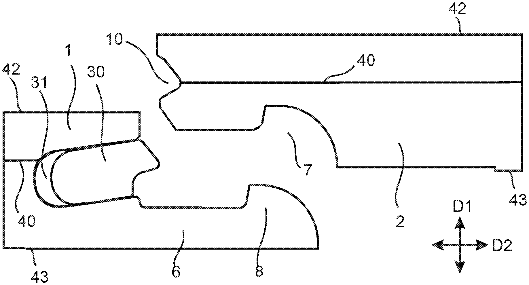
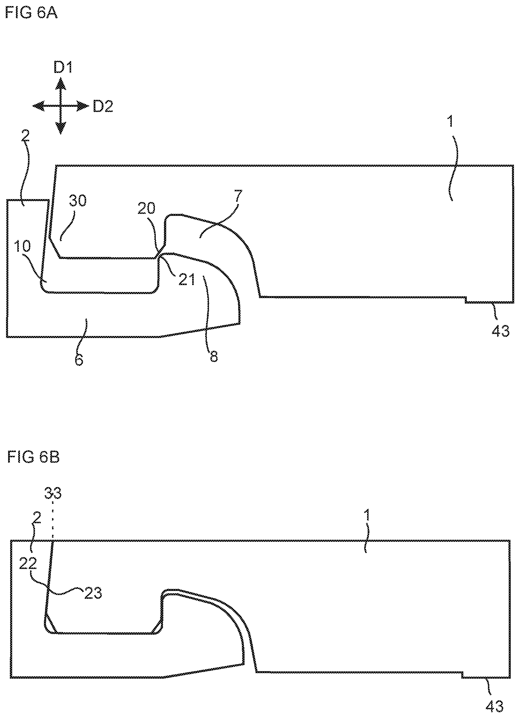
FIG. 6A-B shows an embodiment of the invention comprising another embodiment of the mechanical locking system at a first panel 1 and a second panel 2 during an assembling. The mechanical locking system comprises a locking element 8 at the second edge of the second panel 2. The locking element is configured to cooperate with a locking groove 7 at the first edge of the first panel 2 for locking the first edge to the second edge in the second direction D2. The locking element 8 is preferably arranged on a locking strip 6 protruding from the second edge and the locking groove 7 is at a lower surface 43 of first panel. An upper edge of the locking element 8 comprising a second guiding surface 21 and a lower a lower edge at the opening of the looking groove 7 comprises a first guiding surface 20. An upper most edge of the first panel and an upper most edge of the second panel may be in contact at a joint plane 33. The first edge comprises a tongue 30 at the joint plane and the second edge comprises a tongue groove 10 at the joint plane. The tongue and the tongue groove at the joint plane are configured to cooperate for locking the first edge to the second edge in the first direction D1. The tongue and the tongue groove are preferably formed of a core material of the first panel 1 and the second panel 2, respectively. The first panel and the second panel are, during the assembling, displaced vertically relative each other in the first direction D1, as shown in FIG. 6A, such that the first guiding surface 20 and the second guiding surface 21 cooperate with each other. The first panel and the second panel are shown in a locked position in FIG. 6B. A first locking surface 22 of the tongue and a second locking surface 23 of the tongue groove cooperate with each other in the locked position.
The first and the second panels may comprise a core material comprising a polymer material.
The polymer material may be one or more of the materials: Vinyls, such as polyvinyl chloride and polyvinyl butyral; Polyolefins, such as PE and PP; Polyesters, including polyethylene terephthalate (PET); Styrenics, such as polystyrene; Acrylics, such as PMMA; co-polymers, such as co-polymers including one or more of the above materials; and polymer blends, such as polymer blends including one or more of the above materials.
The core material may comprise a filler and/or a reinforcement material.
The reinforcement material may be arranged as a reinforcement layer 40 extending essentially parallel to an upper surface 42 of the first and the second panel, respectively. Said reinforcement layer may increase the friction and may therefore be arranged such that an outer edge of the reinforcement layer is preferably at a non-guiding surface, such as a bottom surface of the tongue groove.
The filler material may be one or more of wood fibre, preferably as dust, or chalk.
The reinforcement material may be one or more of calcium silicate, e.g., wollastonite, or glass fiber.
A method for producing an embodiment of a mechanical locking system for a first panel and a second panel, such as building panels or floor panels, comprises: providing a tongue 30, comprising a first locking surface 22, at a first edge of the first panel 1, forming a tongue groove 10, comprising a second locking surface 23, preferably by mechanical cutting, at a second edge of the second panel, said first and second locking surface are configured to cooperate for locking the first edge to the second edge in a first direction D1, providing a first guiding surface 20 at the first edge and a second guiding surface 21 at the second edge, wherein the mechanical locking system is configured such that first guiding surface cooperates with the second guiding surface during an assembling of the first edge and the second edge working of the first and/or the second guiding surface to reduce the coefficient of friction.
The first and/or the second guiding surface of the above described mechanical locking system preferably has a lower coefficient of friction and/or a finer surface roughness than an adjacent surface in the locking system. For example, an adjacent surface produced by the same or similar process step, such as mechanical cutting.
The mechanical locking system may be produced by mechanical cutting, such as milling, preferably in a milling line. Said working of the first guiding surface and/or the second guiding surface to reduce the coefficient of friction a surface roughness may be made in the milling line. The mechanical cutting may result in a guiding surface with a high friction coefficient and/or a coarse surface roughness.
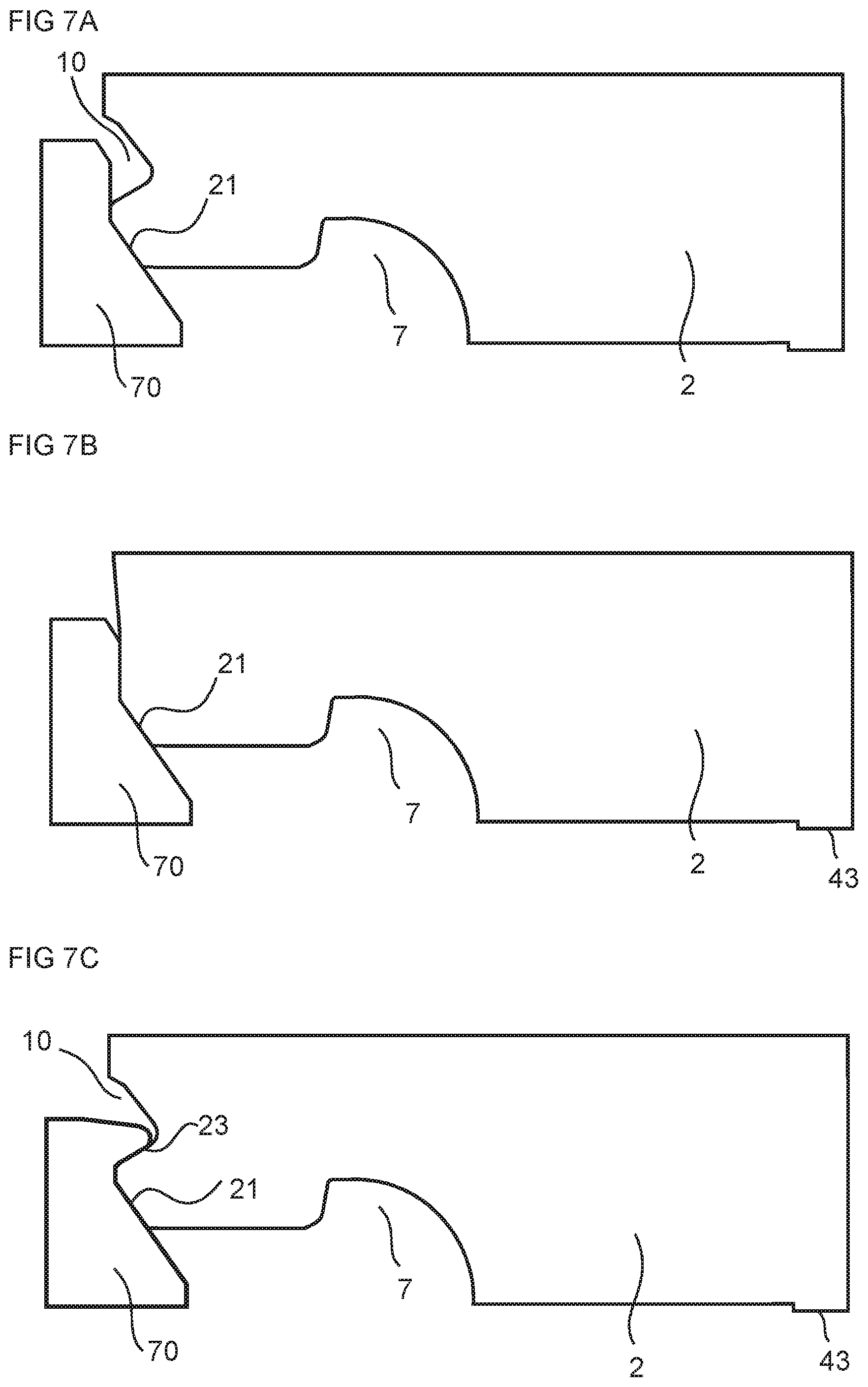
FIG. 7A-7C shows embodiment of the working of the second guiding surface 21 by a tool 70. The working of the second guiding surface may be a polishing, a sanding, a grinding, and/or a pressing by, e.g., a fixed tool, such as a sliding bar or pressure shoe
The fixed tool may for example reduce the surface roughness of the second guiding surface within the range of about 30% to about 50%, or about 30% to about 40%. The surface roughness value may be decreased from about 3 Ra to about 2 Ra. For example, the surface roughness may be decreased at least 0.5 Ra, such as at least 0.8 Ra, such as at least 1 Ra. For example, the surface roughness may be decreased to a value of less than about 2.5 Ra, such as less than 2.2 Ra, such as less than 2 Ra. Such a decrease of surface roughness may result in a considerable reduction of the coefficient of friction. This may have the effect that the assembling of first panel and the second panel changes from being difficult to easy, or for some embodiments from being impossible to easy.
The surface roughness may be measured with a diamond stylus profilometer, such as E-35B from Accretech.
An embodiment may comprise a core comprising a wood based material, such as MDF or MDF. The surface roughness value for this embodiment may be decreased from about 5 Ra to about 3 Ra. For example, the surface roughness may be decreased at least 1 Ra, such as at least 1.5 Ra, such as at least 2 Ra. For example, the surface roughness may be decreased to a value of less than about 4 Ra, such as less than 3.5 Ra, such as less than 3 Ra. The working of the first guiding surface and/or the second guiding surface of this embodiment preferably reduces the surface roughness within the range of about 30% to about 50%, or about 30% to about 40%.
The method and the tool for working the first guiding surface may work the second guiding surface and an adjacent surface which may also be a guiding surface, as shown in the FIGS. 7A-7C. The tool may also have a shape configured such that only the second guiding surface is being worked (not shown). FIG. 7A shows an embodiment comprising working of the second guiding surface after the tongue groove 10 is formed. FIG. 7B shows a preferred embodiment comprising working of the second guiding surface before the tongue groove is formed. FIG. 7C shows an embodiment comprising working of the second guiding surface 21 and the second locking surface 23, at the same time and with an embodiment of the tool 70.
The method and the tool for working the first guiding surface, the third guiding surface or the fourth guiding surface (not shown) may be the same or similar with a shape that is adapted to the first guiding surface, the third guiding surface and the fourth guiding surface, respectively.
The fixed tool may be of metal, such as steel, and preferably comprises a surface of hard metal or diamond.
The method may comprise forming an insertion groove 20, preferably by mechanical cutting, at the first edge and arranging the tongue 30, preferably a displaceable tongue, in the insertion groove 20 by an inserting machine preferably arranged in the milling line.
The method may comprise forming the tongue, preferably by mechanical cutting in the milling line, at the first edge.
The method may comprise: forming a locking element 8 at the first or the second edge, preferably by mechanical cutting in the milling line; and forming a locking groove 7 at the other of the first or the second edge, preferably by mechanical cutting in the milling line, wherein the locking element is configured to cooperate with the locking groove for locking the first edge to the second edge in a second direction D2 which is perpendicular to the first direction D1.
The method may comprise forming, preferably in the milling line, the tongue at the locking element or the locking groove and the tongue groove at the other of the locking element or locking groove.
The method may comprise forming, preferably in the milling line, one or more of the tongue, the tongue groove, the locking element and the locking groove of a core material of the first and/or the second panel.
Any embodiment of the mechanical locking system described above may be produced by embodiments of the method described above.
Embodiments
1. A method for producing a mechanical locking system for a first panel and a second panel, such as building panels or floor panels, wherein the method comprises: providing a tongue (30), comprising a first locking surface (22), at a first edge of the first panel (1); forming a tongue groove (10), comprising a second locking surface (23), preferably by mechanical cutting, at a second edge of the second panel, said first locking surface and second locking surface are configured to cooperate for locking the first edge to the second edge in a first direction (D1); providing a first guiding surface (20) at the first edge and a second guiding surface (21) at the second edge, wherein the mechanical locking system is configured such that first guiding surface cooperates with the second guiding surface during an assembling of the first edge and the second edge; and working of the first guiding surface and/or the second guiding surface to reduce a coefficient of friction between the first guiding surface and the second guiding surface and/or to reduce a surface roughness of the worked guiding surface(s).
2. The method as in embodiment 1, comprising working the second guiding surface, wherein the method for forming the second locking surface (23) is different from the method for working of the second guiding surface (21).
3. The method as in embodiment 1 or 2, comprising working the first guiding surface, wherein a method for forming the first locking surface (23) is different from the method for working of the first guiding surface (20).
4. The method as in any one of the embodiments 1-3, wherein the working of the first guiding surface and/or the second guiding surface is a polishing, a sanding, a grinding and/or pressing by, e.g., a fixed tool, such as a sliding bar or pressure shoe.
5. The method as in any one of the embodiments 1-5, wherein the first panel and the second panels comprises a core material comprising a polymer material, such as a thermoplastic material.
6. The method as in embodiment 5, wherein the core material comprises a filler and/or a reinforcement material.
7. The method as in any one of the embodiments 1-6, wherein the working of the guiding surface is made before the forming of the tongue groove.
8. The method as in any one of the embodiments 1-7, wherein the method comprises forming an insertion groove (31), preferably by mechanical cutting, at the first edge and arranging the tongue (30), preferably a displaceable tongue, in the insertion groove (20).
9. The method as in any one of the embodiments 1-7, wherein the method comprises forming the tongue, preferably by mechanical cutting, at the first edge.
10. The method as in any one of the preceding embodiments, wherein the method comprises: forming a locking element (8) at the first edge or the second edge, preferably by mechanical cutting; and forming a locking groove (7) at the other of the first edge or the second edge, preferably by mechanical cutting, wherein the locking element is configured to cooperate with the locking groove for locking the first edge to the second edge in a second direction (D2) which is perpendicular to the first direction (D1).
11. The method as in embodiment 10, wherein the tongue is formed at the locking element or the locking groove and the tongue groove is formed at the other of the locking element or locking groove.
12. The method as in any one of the preceding embodiments, wherein one or more of the tongue, the tongue groove, the locking element and the locking groove are formed of a core material of the first and or the second panel.
13. The method as in any one of the preceding embodiments, wherein the working of the first guiding surface and/or the second guiding surface reduces the surface roughness value within the range of about 30% to about 50%, or from about 30% to about 40%.
14. The method as in any one of the preceding embodiments, wherein the working of the first guiding surface and/or the second guiding surface reduces the surface roughness to a value of less than about 2.5 Ra, such as less than 2.2 Ra, such as less than 2 Ra.
15. The method as in any one of the preceding embodiments, wherein the working of the first guiding surface and/or the second guiding surface decreases the surface roughness value at least 0.5 Ra, such as at least 0.8 Ra, such as at least 1 Ra.
16. The method as in any one of the preceding embodiments, wherein the working of the first guiding surface and/or the second guiding surface reduces the surface roughness value from about 3 Ra to about 2 Ra.
* * * * *
References
D00000
D00001
D00002
D00003
D00004
D00005
D00006
D00007
XML
uspto.report is an independent third-party trademark research tool that is not affiliated, endorsed, or sponsored by the United States Patent and Trademark Office (USPTO) or any other governmental organization. The information provided by uspto.report is based on publicly available data at the time of writing and is intended for informational purposes only.
While we strive to provide accurate and up-to-date information, we do not guarantee the accuracy, completeness, reliability, or suitability of the information displayed on this site. The use of this site is at your own risk. Any reliance you place on such information is therefore strictly at your own risk.
All official trademark data, including owner information, should be verified by visiting the official USPTO website at www.uspto.gov. This site is not intended to replace professional legal advice and should not be used as a substitute for consulting with a legal professional who is knowledgeable about trademark law.