Swivel assembly for oral irrigator handle
Williams , et al. November 17, 2
U.S. patent number 10,835,356 [Application Number 15/415,836] was granted by the patent office on 2020-11-17 for swivel assembly for oral irrigator handle. This patent grant is currently assigned to WATER PIK, INC.. The grantee listed for this patent is WATER PIK, INC.. Invention is credited to Jeremy Johnson, Leland C. Leber, Brian R. Williams.


View All Diagrams
| United States Patent | 10,835,356 |
| Williams , et al. | November 17, 2020 |
Swivel assembly for oral irrigator handle
Abstract
An oral irrigator handle has a handle housing with a swivel assembly for connection to a hose further connected to a fluid source. A tip for directing a focused stream of fluid is releasably connected to a first end of the handle. The swivel assembly is received within the housing and fluidly coupled to tip. The hose is connected to the swivel assembly and fluidly coupled to the tip via the swivel assembly. The swivel assembly prevents translation of rotational movement of the handle or the hose to the other.
| Inventors: | Williams; Brian R. (Fort Collins, CO), Johnson; Jeremy (Longmont, CO), Leber; Leland C. (Fort Collins, CO) | ||||||||||
|---|---|---|---|---|---|---|---|---|---|---|---|
| Applicant: |
|
||||||||||
| Assignee: | WATER PIK, INC. (Fort Collins,
CO) |
||||||||||
| Family ID: | 59360974 | ||||||||||
| Appl. No.: | 15/415,836 | ||||||||||
| Filed: | January 25, 2017 |
Prior Publication Data
| Document Identifier | Publication Date | |
|---|---|---|
| US 20170209246 A1 | Jul 27, 2017 | |
Related U.S. Patent Documents
| Application Number | Filing Date | Patent Number | Issue Date | ||
|---|---|---|---|---|---|
| 62286792 | Jan 25, 2016 | ||||
| 62286925 | Jan 25, 2016 | ||||
| 62416926 | Nov 3, 2016 | ||||
| Current U.S. Class: | 1/1 |
| Current CPC Class: | A61C 17/0202 (20130101); A61M 39/1055 (20130101); A61C 17/032 (20190501); A61C 17/14 (20130101); A61C 17/00 (20130101); A61C 1/0061 (20130101); F16L 27/00 (20130101) |
| Current International Class: | A61C 17/02 (20060101); A61C 17/032 (20060101); A61M 39/10 (20060101); A61C 1/00 (20060101); A61C 17/00 (20060101); A61C 17/14 (20060101); F16L 27/00 (20060101) |
References Cited [Referenced By]
U.S. Patent Documents
| 555588 | March 1896 | Spencer |
| 1278225 | September 1918 | Schamberg |
| 1452258 | April 1923 | Smith |
| 1464419 | August 1923 | Gill |
| 1480310 | January 1924 | Smith |
| 1498267 | June 1924 | Hachman |
| 1650686 | November 1927 | Binks |
| 1669889 | May 1928 | Andrews et al. |
| 1681320 | August 1928 | Bergl et al. |
| 1933454 | October 1933 | Sidney |
| 1940111 | December 1933 | Austin |
| D93019 | August 1934 | Hose |
| 1977782 | October 1934 | Roy |
| 2107686 | February 1938 | Bramsen et al. |
| 2124747 | July 1938 | Pieper |
| 2171292 | August 1939 | Pieper |
| D159872 | August 1950 | Skold |
| 2531730 | November 1950 | Henderson |
| 2595666 | May 1952 | Hutson |
| 2669233 | February 1954 | Friend |
| 2709227 | May 1955 | Foley et al. |
| 2783919 | March 1957 | Ansell |
| 2794437 | June 1957 | Tash |
| 2870932 | January 1959 | Davis |
| 2984452 | May 1961 | Hooper |
| 3089490 | May 1963 | Goldberg |
| 3096913 | July 1963 | Jousson |
| 3144867 | August 1964 | Trupp et al. |
| D202041 | August 1965 | Burzlaff |
| 3209956 | October 1965 | McKenzie |
| 3216619 | November 1965 | Richards et al. |
| 3225759 | December 1965 | Drapen et al. |
| 3227158 | January 1966 | Mattingly |
| 3266623 | August 1966 | Poferl |
| 3297558 | January 1967 | Hillquist |
| D208778 | October 1967 | Koch |
| D209204 | November 1967 | St. Clair et al. |
| D209395 | November 1967 | Gilbert |
| D210018 | January 1968 | Mattingly et al. |
| D210019 | January 1968 | Johnson et al. |
| 3370214 | February 1968 | Aymar |
| 3391696 | July 1968 | Woodward |
| 3393673 | July 1968 | Mattingly et al. |
| 3393676 | July 1968 | Kummer et al. |
| 3400999 | September 1968 | Goldstein |
| 3418552 | December 1968 | Holmes |
| 3420228 | January 1969 | Kalbfeld |
| 3425410 | February 1969 | Cammack |
| 3453969 | July 1969 | Mattingly |
| 3465751 | September 1969 | Powers |
| 3467083 | September 1969 | Mattingly |
| D215920 | November 1969 | McCarty et al. |
| 3487828 | January 1970 | Troy |
| 3489268 | January 1970 | Meierhoefer |
| 3495587 | February 1970 | Freedman |
| 3496933 | February 1970 | Lloyd |
| 3499440 | March 1970 | Gibbs |
| 3500824 | March 1970 | Gilbert |
| 3501203 | March 1970 | Falk |
| 3502072 | March 1970 | Stillman |
| 3517669 | June 1970 | Buono et al. |
| D218270 | August 1970 | Soper |
| 3522801 | August 1970 | Robinson |
| 3532221 | October 1970 | Kaluhiokalani et al. |
| 3536065 | October 1970 | Moret |
| 3537444 | November 1970 | Garn |
| 3538950 | November 1970 | Porteners |
| 3547110 | December 1970 | Balamuth |
| 3561433 | February 1971 | Kovach |
| D220334 | March 1971 | Mackey et al. |
| 3570525 | March 1971 | Borsum |
| 3572375 | March 1971 | Rosenberg |
| 3578884 | May 1971 | Jacobson |
| D220996 | June 1971 | Irons |
| 3583609 | June 1971 | Oppenheimer |
| 3590813 | July 1971 | Roszyk |
| 3608548 | September 1971 | Lewis |
| D222862 | January 1972 | Cook |
| 3636947 | January 1972 | Balamuth |
| 3651576 | March 1972 | Massa |
| 3669101 | June 1972 | Kleiner |
| 3703170 | November 1972 | Ryckman, Jr. |
| 3747595 | July 1973 | Grossan |
| 3768472 | October 1973 | Hodosh et al. |
| 3783364 | January 1974 | Gallanis et al. |
| 3809506 | May 1974 | Malcosky |
| 3809977 | May 1974 | Balamuth et al. |
| 3811432 | May 1974 | Moret |
| 3820532 | June 1974 | Eberhardt et al. |
| 3827147 | August 1974 | Condon |
| 3837166 | September 1974 | Hiraoka |
| 3840795 | October 1974 | Roszyk et al. |
| 3847145 | November 1974 | Grossan |
| 3851643 | December 1974 | Musy |
| 3854209 | December 1974 | Franklin et al. |
| 3863628 | February 1975 | Vit |
| 3871560 | March 1975 | Crippa |
| 3874506 | April 1975 | Hill et al. |
| 3912125 | October 1975 | Acklin |
| 3921297 | November 1975 | Vit |
| 3943628 | March 1976 | Kronman et al. |
| 3959883 | June 1976 | Walls et al. |
| 3973558 | August 1976 | Stouffer et al. |
| 3977084 | August 1976 | Sloan |
| 4001526 | January 1977 | Olson |
| 4004302 | January 1977 | Hori |
| 4007739 | February 1977 | Bron et al. |
| 4013227 | March 1977 | Herrera |
| 4015336 | April 1977 | Johnson |
| 4052002 | October 1977 | Stouffer et al. |
| D246667 | December 1977 | Mackay et al. |
| 4060870 | December 1977 | Cannarella |
| 4075761 | February 1978 | Behne et al. |
| 4078558 | March 1978 | Woog et al. |
| 4094311 | June 1978 | Hudson |
| 4108167 | August 1978 | Hickman et al. |
| 4108178 | August 1978 | Betush |
| 4109650 | August 1978 | Peclard |
| 4122845 | October 1978 | Stouffer et al. |
| 4135501 | January 1979 | Leunissan |
| 4141352 | February 1979 | Ebner et al. |
| 4144646 | March 1979 | Takemoto et al. |
| 4149315 | April 1979 | Page, Jr. et al. |
| 4154375 | May 1979 | Bippus |
| 4160383 | July 1979 | Rauschenberger |
| 4171572 | October 1979 | Nash |
| 4182038 | January 1980 | Fleer |
| 4200235 | April 1980 | Monschke |
| 4201200 | May 1980 | Hubner |
| 4215476 | August 1980 | Armstrong |
| 4219618 | August 1980 | Leonard |
| 4227878 | October 1980 | Lohn |
| 4229634 | October 1980 | Hickman et al. |
| 4236889 | December 1980 | Wright |
| D258097 | February 1981 | Wistrand |
| 4248589 | February 1981 | Lewis |
| 4249899 | February 1981 | Davis |
| 4257458 | March 1981 | Kondo et al. |
| 4262799 | April 1981 | Perrett |
| 4266934 | May 1981 | Pernot |
| 4276023 | June 1981 | Phillips et al. |
| 4276880 | July 1981 | Malmin |
| 4302186 | November 1981 | Cammack et al. |
| 4303064 | December 1981 | Buffa |
| 4303070 | December 1981 | Ichikawa et al. |
| 4306862 | December 1981 | Knox |
| 4315741 | February 1982 | Reichl |
| 4319568 | March 1982 | Tregoning |
| 4331422 | May 1982 | Heyman |
| 4337040 | June 1982 | Cammack et al. |
| 4340365 | July 1982 | Pisanu |
| 4340368 | July 1982 | Lococo |
| D266117 | September 1982 | Oberheim |
| 4353694 | October 1982 | Pelerin |
| 4363626 | December 1982 | Schmidt et al. |
| 4365376 | December 1982 | Oda et al. |
| 4370131 | January 1983 | Banko |
| 4374354 | February 1983 | Petrovic et al. |
| 4382167 | May 1983 | Maruyama et al. |
| 4382786 | May 1983 | Lohn |
| D270000 | August 1983 | Ketler |
| 4412823 | November 1983 | Sakai et al. |
| 4416628 | November 1983 | Cammack |
| 4442830 | April 1984 | Markau |
| 4442831 | April 1984 | Trenary |
| 4452238 | June 1984 | Kerr |
| 4454866 | June 1984 | Fayen |
| 4512769 | April 1985 | Kozam et al. |
| 4517962 | May 1985 | Heckele |
| 4531912 | July 1985 | Schuss et al. |
| 4531913 | July 1985 | Taguchi |
| 4534340 | August 1985 | Kerr et al. |
| 4552130 | November 1985 | Kinoshita |
| 4561214 | December 1985 | Inoue |
| D283374 | April 1986 | Cheuk-Yiu |
| 4585415 | April 1986 | Hommann |
| 4591777 | May 1986 | McCarty et al. |
| 4592728 | June 1986 | Davis |
| 4602906 | July 1986 | Grunenfelder |
| 4607627 | August 1986 | Leber et al. |
| 4613074 | September 1986 | Schulze |
| 4619009 | October 1986 | Rosenstatter |
| 4619612 | October 1986 | Weber et al. |
| 4629425 | December 1986 | Detsch |
| 4636198 | January 1987 | Stade |
| 4642037 | February 1987 | Fritchman |
| 4644937 | February 1987 | Hommann |
| 4645488 | February 1987 | Matukas |
| 4647831 | March 1987 | O'Malley et al. |
| 4648838 | March 1987 | Schlachter |
| 4650475 | March 1987 | Smith et al. |
| 4655198 | April 1987 | Hommann |
| 4669453 | June 1987 | Atkinson et al. |
| 4672953 | June 1987 | DiVito |
| 4673396 | June 1987 | Urbaniak |
| D291354 | August 1987 | Camens |
| 4716352 | December 1987 | Hurn et al. |
| 4749340 | June 1988 | Ikeda et al. |
| 4770632 | September 1988 | Ryder et al. |
| D298565 | November 1988 | Kohler, Jr. et al. |
| 4783321 | November 1988 | Spence |
| 4787845 | November 1988 | Valentine |
| 4787847 | November 1988 | Martin et al. |
| 4798292 | January 1989 | Hauze |
| 4803974 | February 1989 | Powell |
| 4804364 | February 1989 | Dieras et al. |
| 4818229 | April 1989 | Vasile |
| 4820152 | April 1989 | Warrin et al. |
| 4821923 | April 1989 | Skorka |
| 4824368 | April 1989 | Hickman |
| 4826431 | May 1989 | Fujimura et al. |
| 4827551 | May 1989 | Maser et al. |
| 4832683 | May 1989 | Idemoto et al. |
| 4854869 | August 1989 | Lawhorn |
| 4861340 | August 1989 | Smith et al. |
| 4862876 | September 1989 | Lih-Sheng |
| 4869720 | September 1989 | Chernack |
| 4880382 | November 1989 | Moret et al. |
| 4886452 | December 1989 | Lohn |
| 4900252 | February 1990 | Liefke et al. |
| 4902225 | February 1990 | Lohn |
| 4903687 | February 1990 | Lih-Sheng |
| 4906187 | March 1990 | Amadera |
| 4907744 | March 1990 | Jousson |
| 4925450 | May 1990 | Imonti et al. |
| 4928675 | May 1990 | Thornton |
| 4930660 | June 1990 | Porteous |
| 4941459 | July 1990 | Mathur |
| 4950159 | August 1990 | Hansen |
| 4958629 | September 1990 | Peace et al. |
| 4958751 | September 1990 | Curtis et al. |
| 4959199 | September 1990 | Brewer |
| 4961698 | October 1990 | Vlock |
| 4966551 | October 1990 | Betush |
| 4969874 | November 1990 | Michel et al. |
| 4973246 | November 1990 | Black |
| 4973247 | November 1990 | Varnes et al. |
| 4973250 | November 1990 | Milman |
| 4975054 | December 1990 | Esrock |
| 4979503 | December 1990 | Chernack |
| 4979504 | December 1990 | Mills |
| 4989590 | February 1991 | Baum et al. |
| 4998880 | March 1991 | Nerli |
| 5013241 | May 1991 | Von Gutfeld et al. |
| 5013300 | May 1991 | Williams |
| 5014884 | May 1991 | Wunsch |
| 5019054 | May 1991 | Clement et al. |
| 5027798 | July 1991 | Primiano |
| 5029576 | July 1991 | Evans, Sr. |
| 5033617 | July 1991 | Hartwein et al. |
| 5033961 | July 1991 | Kandler et al. |
| D318918 | August 1991 | Hartwein |
| 5046486 | September 1991 | Grulke et al. |
| 5049071 | September 1991 | Davis et al. |
| 5060825 | October 1991 | Palmer et al. |
| 5061180 | October 1991 | Wiele |
| 5062795 | November 1991 | Woog |
| 5064168 | November 1991 | Raines et al. |
| D322314 | December 1991 | Ohbayashi |
| 5071346 | December 1991 | Domaas |
| 5082115 | January 1992 | Hutcheson |
| 5082443 | January 1992 | Lohn |
| 5085317 | February 1992 | Jensen et al. |
| 5086756 | February 1992 | Powell |
| 5086788 | February 1992 | Castel |
| 5095893 | March 1992 | Rawden, Jr. |
| 5098291 | March 1992 | Curtis et al. |
| 5098676 | March 1992 | Brooks, Jr. |
| 5100319 | March 1992 | Baum |
| 5117871 | June 1992 | Gardner et al. |
| 5125835 | June 1992 | Young |
| 5127831 | July 1992 | Bab |
| 5142723 | September 1992 | Lustig et al. |
| 5150841 | September 1992 | Silvenis et al. |
| 5172810 | December 1992 | Brewer |
| 5173273 | December 1992 | Brewer |
| 5183035 | February 1993 | Weir |
| 5197458 | March 1993 | Ito et al. |
| 5197460 | March 1993 | Ito et al. |
| 5199871 | April 1993 | Young |
| 5203697 | April 1993 | Malmin |
| 5203769 | April 1993 | Clement et al. |
| 5204004 | April 1993 | Johnston et al. |
| 5208933 | May 1993 | Lustig et al. |
| 5215193 | June 1993 | Dennis |
| 5218956 | June 1993 | Handler et al. |
| 5220914 | June 1993 | Thompson |
| 5228646 | July 1993 | Raines |
| 5230624 | July 1993 | Wolf et al. |
| 5232687 | August 1993 | Geimer |
| 5235968 | August 1993 | Woog |
| 5241714 | September 1993 | Barry |
| 5246367 | September 1993 | Ito et al. |
| 5252064 | October 1993 | Baum et al. |
| D341200 | November 1993 | Yoshimoto |
| 5257933 | November 1993 | Jousson |
| 5261448 | November 1993 | Furuya et al. |
| D341943 | December 1993 | Si-Hoe |
| 5267586 | December 1993 | Jankavaara |
| 5269684 | December 1993 | Fischer |
| 5281137 | January 1994 | Jousson |
| 5281139 | January 1994 | Frank et al. |
| 5282745 | February 1994 | Wiltrout et al. |
| 5286192 | February 1994 | Dixon |
| 5286201 | February 1994 | Yu |
| 5295832 | March 1994 | Evans |
| 5297962 | March 1994 | O'Connor et al. |
| D346212 | April 1994 | Hosl |
| 5301381 | April 1994 | Klupt |
| 5302123 | April 1994 | Bechard |
| 5317691 | May 1994 | Traeger |
| 5321865 | June 1994 | Kaeser |
| 5331704 | July 1994 | Rosen et al. |
| 5344317 | September 1994 | Pacher et al. |
| 5346677 | September 1994 | Risk |
| D351892 | October 1994 | Wolf et al. |
| 5360338 | November 1994 | Waggoner |
| 5368548 | November 1994 | Jousson |
| 5370534 | December 1994 | Wolf et al. |
| D354168 | January 1995 | Hartwein |
| D354559 | January 1995 | Knute |
| 5378149 | January 1995 | Stropko |
| 5380201 | January 1995 | Kawata |
| D356864 | March 1995 | Woog |
| 5399089 | March 1995 | Eichman et al. |
| D358883 | May 1995 | Vos |
| 5456672 | October 1995 | Diederich et al. |
| 5465445 | November 1995 | Yeh |
| 5467495 | November 1995 | Boland et al. |
| 5468148 | November 1995 | Ricks |
| 5470305 | November 1995 | Arnett et al. |
| 5474450 | December 1995 | Chronister |
| 5474451 | December 1995 | Dalrymple et al. |
| 5476379 | December 1995 | Disel |
| 5484281 | January 1996 | Renow et al. |
| 5487877 | January 1996 | Choi |
| 5490779 | February 1996 | Malmin |
| 5505916 | April 1996 | Berry, Jr. |
| D369656 | May 1996 | Vos |
| D370125 | May 1996 | Craft et al. |
| 5525058 | June 1996 | Gallant et al. |
| 5526841 | June 1996 | Detsch et al. |
| 5540587 | July 1996 | Malmin |
| 5547374 | August 1996 | Coleman |
| D373631 | September 1996 | Maeda et al. |
| 5554014 | September 1996 | Becker |
| 5554025 | September 1996 | Kinsel |
| 5556001 | September 1996 | Weissman et al. |
| 5564629 | October 1996 | Weissman et al. |
| D376893 | December 1996 | Gornet |
| D377091 | December 1996 | Scott, Sr. |
| 5613259 | March 1997 | Craft et al. |
| 5616028 | April 1997 | Hafele et al. |
| 5626472 | May 1997 | Pennetta |
| 5634791 | June 1997 | Matsuura et al. |
| 5636987 | June 1997 | Serfaty |
| 5640735 | June 1997 | Manning |
| D382407 | August 1997 | Craft et al. |
| 5653591 | August 1997 | Loge |
| 5659995 | August 1997 | Hoffman |
| 5667483 | September 1997 | Santos |
| D386576 | November 1997 | Wang et al. |
| 5683192 | November 1997 | Kilfoil |
| 5685829 | November 1997 | Allen |
| 5685851 | November 1997 | Murphy et al. |
| 5697784 | December 1997 | Hafele et al. |
| D388612 | January 1998 | Stutzer et al. |
| D388613 | January 1998 | Stutzer et al. |
| D389091 | January 1998 | Dickinson |
| 5709545 | January 1998 | Johnston et al. |
| D390934 | February 1998 | McKeone |
| 5716007 | February 1998 | Nottingham et al. |
| 5718668 | February 1998 | Arnett et al. |
| 5746595 | May 1998 | Ford |
| 5749726 | May 1998 | Kinsel |
| 5759502 | June 1998 | Spencer et al. |
| 5779471 | July 1998 | Tseng et al. |
| 5779654 | July 1998 | Foley et al. |
| 5795153 | August 1998 | Rechmann |
| 5796325 | August 1998 | Lundell et al. |
| 5833065 | November 1998 | Burgess |
| 5836030 | November 1998 | Hazeu et al. |
| D402744 | December 1998 | Zuege |
| 5851079 | December 1998 | Horstman et al. |
| D403511 | January 1999 | Serbinski |
| D406334 | March 1999 | Rosenthal et al. |
| 5876201 | March 1999 | Wilson et al. |
| D408511 | April 1999 | Allen et al. |
| 5901397 | May 1999 | Hafele et al. |
| 5934902 | August 1999 | Abahusayn |
| D413975 | September 1999 | Maeda |
| D416999 | November 1999 | Miyamoto |
| D417082 | November 1999 | Classen et al. |
| 5993402 | November 1999 | Sauer et al. |
| 6030215 | February 2000 | Ellion et al. |
| 6038960 | March 2000 | Fukushima et al. |
| 6039180 | March 2000 | Grant |
| 6047429 | April 2000 | Wu |
| D424181 | May 2000 | Caplow |
| D425615 | May 2000 | Bachman et al. |
| D425981 | May 2000 | Bachman et al. |
| 6056710 | May 2000 | Bachman et al. |
| D426633 | June 2000 | Bachman et al. |
| 6089865 | July 2000 | Edgar |
| 6116866 | September 2000 | Tomita et al. |
| 6120755 | September 2000 | Jacobs |
| 6124699 | September 2000 | Suzuki et al. |
| D434500 | November 2000 | Pollock et al. |
| 6159006 | December 2000 | Cook et al. |
| 6164967 | December 2000 | Sale et al. |
| D435905 | January 2001 | Bachman et al. |
| D437049 | January 2001 | Hartwein |
| 6193512 | February 2001 | Wallace |
| 6193932 | February 2001 | Wu et al. |
| 6199239 | March 2001 | Dickerson |
| 6200134 | March 2001 | Kovac |
| D439781 | April 2001 | Spore |
| 6217835 | April 2001 | Riley et al. |
| D441861 | May 2001 | Hafliger |
| 6233773 | May 2001 | Karge et al. |
| 6234205 | May 2001 | D'Amelio et al. |
| 6237178 | May 2001 | Krammer et al. |
| 6238211 | May 2001 | Esrock |
| 6247929 | June 2001 | Bachman et al. |
| 6280190 | August 2001 | Hoffman |
| D448236 | September 2001 | Murray |
| 6293792 | September 2001 | Hanson |
| D449884 | October 2001 | Tobin et al. |
| D453453 | February 2002 | Lun |
| D455201 | April 2002 | Jones |
| D455203 | April 2002 | Jones |
| 6363565 | April 2002 | Paffrath |
| D457949 | May 2002 | Krug |
| D464799 | October 2002 | Crossman et al. |
| 6468482 | October 2002 | Frieze et al. |
| 6475173 | November 2002 | Bachman et al. |
| 6485451 | November 2002 | Roberts et al. |
| 6497375 | December 2002 | Srinath et al. |
| 6497572 | December 2002 | Hood et al. |
| 6502584 | January 2003 | Fordham |
| D470660 | February 2003 | Schaber |
| 6558344 | May 2003 | McKinnon et al. |
| 6561808 | May 2003 | Neuberger et al. |
| D475346 | June 2003 | McCurrach et al. |
| D476743 | July 2003 | D'Silva |
| 6589477 | July 2003 | Frieze et al. |
| 6602071 | August 2003 | Ellion et al. |
| 6632091 | October 2003 | Cise et al. |
| D482451 | November 2003 | Page et al. |
| 6640999 | November 2003 | Peterson |
| 6647577 | November 2003 | Tam |
| 6659674 | December 2003 | Carlucci et al. |
| 6669059 | December 2003 | Mehta |
| D484971 | January 2004 | Hartwein |
| 6681418 | January 2004 | Bierend |
| D486573 | February 2004 | Callaghan et al. |
| 6689078 | February 2004 | Rehkemper et al. |
| 6699208 | March 2004 | Bachman et al. |
| 6719561 | April 2004 | Gugel et al. |
| D489183 | May 2004 | Akahori et al. |
| 6739782 | May 2004 | Rehkemper et al. |
| 6740053 | May 2004 | Kaplowitz |
| D490899 | June 2004 | Gagnon |
| D491728 | June 2004 | Jimenez |
| D492996 | July 2004 | Rehkemper et al. |
| 6761324 | July 2004 | Chang |
| 6766549 | July 2004 | Klupt |
| D495142 | August 2004 | Berde |
| D495143 | August 2004 | Berde |
| 6779216 | August 2004 | Davies et al. |
| 6783004 | August 2004 | Rinner |
| 6783505 | August 2004 | Lai |
| 6796796 | September 2004 | Segal |
| D498643 | November 2004 | Pryor |
| 6814259 | November 2004 | Foster et al. |
| D499885 | December 2004 | Xi |
| 6835181 | December 2004 | Hippensteel |
| D500599 | January 2005 | Callaghan |
| 6837708 | January 2005 | Chen et al. |
| 6884069 | April 2005 | Goldman |
| 6902337 | June 2005 | Kuo |
| 6907879 | June 2005 | Drinan et al. |
| D509585 | September 2005 | Kling et al. |
| D513638 | January 2006 | Pan |
| D515215 | February 2006 | Wang |
| D522652 | June 2006 | Massey |
| 7080980 | July 2006 | Klupt |
| D529661 | October 2006 | Schmidt |
| D530010 | October 2006 | Luettgen et al. |
| 7117555 | October 2006 | Fattori et al. |
| D532570 | November 2006 | Vizcarra |
| 7131838 | November 2006 | Suzuki et al. |
| D533720 | December 2006 | Vu |
| D538474 | March 2007 | Sheppard et al. |
| D548334 | August 2007 | Izumi |
| D550097 | September 2007 | Lepoitevin |
| D553980 | October 2007 | VerWeyst |
| 7276035 | October 2007 | Lu |
| 7314456 | January 2008 | Shaw |
| D565175 | March 2008 | Boyd et al. |
| 7344510 | March 2008 | Yande |
| D565713 | April 2008 | Gao |
| 7367803 | May 2008 | Egeresi |
| D574952 | August 2008 | Boyd et al. |
| D577198 | September 2008 | Jimenez |
| D577814 | September 2008 | Seki et al. |
| D581279 | November 2008 | Oates |
| 7455521 | November 2008 | Fishburne, Jr. |
| 7469440 | December 2008 | Boland et al. |
| D585132 | January 2009 | Pukall |
| D588262 | March 2009 | Pukall |
| 7500584 | March 2009 | Schutz |
| D590492 | April 2009 | Powell |
| D592748 | May 2009 | Boulton |
| D595136 | June 2009 | Canamasas Puigbo |
| D601694 | October 2009 | Rocklin |
| D601697 | October 2009 | Sobeich et al. |
| D603708 | November 2009 | Handy |
| D608430 | January 2010 | Slothower |
| 7670141 | March 2010 | Thomas et al. |
| 7677888 | March 2010 | Halm |
| D613550 | April 2010 | Picozza et al. |
| D621949 | August 2010 | Seki et al. |
| D622928 | September 2010 | Griebel |
| D623376 | September 2010 | Griebel |
| D625406 | October 2010 | Seki et al. |
| 7814585 | October 2010 | Reich |
| D629884 | December 2010 | Stephens |
| 7857623 | December 2010 | Grez |
| 7862536 | January 2011 | Chen et al. |
| 7959597 | June 2011 | Baker et al. |
| D640872 | July 2011 | Nanda |
| D648539 | November 2011 | Wai |
| D651409 | January 2012 | Papenfu |
| D651805 | January 2012 | Hay |
| D653340 | January 2012 | Goerge et al. |
| 8113832 | February 2012 | Snyder et al. |
| D655380 | March 2012 | Taylor |
| D658381 | May 2012 | Gebski |
| D658538 | May 2012 | Korzeniowski |
| 8220726 | July 2012 | Qiu et al. |
| D666912 | September 2012 | Kawai |
| 8256979 | September 2012 | Hilscher et al. |
| D668339 | October 2012 | Luoto |
| D669169 | October 2012 | Washington et al. |
| 8297534 | October 2012 | Li et al. |
| D670373 | November 2012 | Taylor et al. |
| D670958 | November 2012 | Picozza et al. |
| D671637 | November 2012 | Gebski et al. |
| D672018 | December 2012 | Bucher |
| 8366024 | February 2013 | Leber et al. |
| 8403577 | March 2013 | Khoshnevis |
| 8403665 | March 2013 | Thomas et al. |
| 8408483 | April 2013 | Boyd et al. |
| D686311 | July 2013 | Mori |
| D694378 | November 2013 | Bates |
| D694398 | November 2013 | Taylor |
| D700343 | February 2014 | Liu |
| D702819 | April 2014 | Garland |
| D702821 | April 2014 | Garland |
| D707350 | June 2014 | Woodard |
| D709183 | July 2014 | Kemlein |
| D714929 | October 2014 | Kim et al. |
| D714930 | October 2014 | Kim et al. |
| D717412 | November 2014 | Bucher |
| D717427 | November 2014 | Kim |
| D718855 | December 2014 | Kim et al. |
| D723387 | March 2015 | Fath |
| D725770 | March 2015 | Kim et al. |
| D731640 | June 2015 | Kim et al. |
| D735305 | July 2015 | Obara |
| D740936 | October 2015 | Kim et al. |
| D745329 | December 2015 | Ong |
| D746975 | January 2016 | Schenck |
| D747464 | January 2016 | Taylor |
| D754330 | April 2016 | Kim et al. |
| D756122 | May 2016 | Taylor |
| D764051 | August 2016 | Wang |
| D766423 | September 2016 | Kim et al. |
| D772396 | November 2016 | Kim et al. |
| D772397 | November 2016 | Kim et al. |
| D774651 | December 2016 | Kaib |
| D776253 | January 2017 | Li |
| D782326 | March 2017 | Fath |
| D782656 | March 2017 | Au |
| D786422 | May 2017 | Au |
| 2002/0090252 | July 2002 | Hall et al. |
| 2002/0108193 | August 2002 | Gruber |
| 2002/0119415 | August 2002 | Bailey |
| 2002/0152565 | October 2002 | Klupt |
| 2003/0060743 | March 2003 | Chang |
| 2003/0098249 | May 2003 | Rollock |
| 2003/0204155 | October 2003 | Egeresi |
| 2003/0213075 | November 2003 | Hui et al. |
| 2004/0045107 | March 2004 | Egeresi |
| 2004/0076921 | April 2004 | Gofman et al. |
| 2004/0122377 | June 2004 | Fischer et al. |
| 2004/0126730 | July 2004 | Panagotacos |
| 2004/0209222 | October 2004 | Snyder |
| 2005/0049620 | March 2005 | Chang |
| 2005/0064371 | March 2005 | Soukos et al. |
| 2005/0101894 | May 2005 | Hippensteel |
| 2005/0102773 | May 2005 | Obermann et al. |
| 2005/0144745 | July 2005 | Russell |
| 2005/0177079 | August 2005 | Pan |
| 2005/0271531 | December 2005 | Brown et al. |
| 2006/0008373 | January 2006 | Schutz |
| 2006/0010624 | January 2006 | Cleland |
| 2006/0026784 | February 2006 | Moskovich et al. |
| 2006/0057539 | March 2006 | Sodo |
| 2006/0078844 | April 2006 | Goldman et al. |
| 2006/0079818 | April 2006 | Yande |
| 2007/0077810 | April 2007 | Gogel et al. |
| 2007/0082316 | April 2007 | Zhadanov et al. |
| 2007/0082317 | April 2007 | Chuang |
| 2007/0113360 | May 2007 | Tsai |
| 2007/0199616 | August 2007 | Chotenovsky |
| 2007/0202459 | August 2007 | Boyd et al. |
| 2007/0203439 | August 2007 | Boyd et al. |
| 2007/0254260 | November 2007 | Alden |
| 2008/0189951 | August 2008 | Molema et al. |
| 2008/0213719 | September 2008 | Giniger et al. |
| 2009/0070949 | March 2009 | Sagel et al. |
| 2009/0082706 | March 2009 | Shaw |
| 2009/0124945 | May 2009 | Reich et al. |
| 2009/0163839 | June 2009 | Alexander |
| 2009/0188780 | July 2009 | Watanabe |
| 2009/0281454 | November 2009 | Baker et al. |
| 2010/0010524 | January 2010 | Barrington |
| 2010/0015566 | January 2010 | Shaw |
| 2010/0190132 | July 2010 | Taylor et al. |
| 2010/0239998 | September 2010 | Snyder et al. |
| 2010/0261134 | October 2010 | Boyd et al. |
| 2010/0261137 | October 2010 | Boyd et al. |
| 2010/0326536 | December 2010 | Nan |
| 2010/0330527 | December 2010 | Boyd et al. |
| 2011/0027749 | February 2011 | Syed |
| 2011/0076090 | March 2011 | Wu et al. |
| 2011/0097683 | April 2011 | Boyd et al. |
| 2011/0139826 | June 2011 | Hair et al. |
| 2011/0144588 | June 2011 | Taylor et al. |
| 2011/0184341 | July 2011 | Baker et al. |
| 2011/0307039 | December 2011 | Cornell |
| 2012/0021374 | January 2012 | Cacka et al. |
| 2012/0045730 | February 2012 | Snyder et al. |
| 2012/0064480 | March 2012 | Hegemann |
| 2012/0077145 | March 2012 | Tsurukawa |
| 2012/0141952 | June 2012 | Snyder et al. |
| 2012/0179118 | July 2012 | Hair |
| 2012/0189976 | July 2012 | McDonough et al. |
| 2012/0266396 | October 2012 | Leung |
| 2012/0277677 | November 2012 | Taylor et al. |
| 2012/0277678 | November 2012 | Taylor et al. |
| 2012/0279002 | November 2012 | Sokol et al. |
| 2012/0295220 | November 2012 | Thomas et al. |
| 2013/0140382 | June 2013 | Eley |
| 2013/0295520 | November 2013 | Hsieh |
| 2014/0106296 | April 2014 | Woodard et al. |
| 2014/0193774 | July 2014 | Snyder et al. |
| 2014/0259474 | September 2014 | Sokol et al. |
| 2014/0272769 | September 2014 | Luettgen et al. |
| 2014/0272782 | September 2014 | Luettgen et al. |
| 2014/0352088 | December 2014 | Wu |
| 2014/0356810 | December 2014 | Novak |
| 2015/0004559 | January 2015 | Luettgen et al. |
| 2015/0147717 | May 2015 | Taylor et al. |
| 2015/0173850 | June 2015 | Garrigues et al. |
| 2015/0182319 | July 2015 | Wagner et al. |
| 2016/0100921 | April 2016 | Ungar |
| 2016/0151133 | June 2016 | Luettgen et al. |
| 2017/0114495 | April 2017 | Date |
| 851479 | Sep 1970 | CA | |||
| 655237 | Apr 1986 | CH | |||
| 201691300 | Jan 2011 | CN | |||
| 201754925 | Mar 2011 | CN | |||
| 204049908 | Dec 2014 | CN | |||
| 1466963 | May 1969 | DE | |||
| 2019003 | Nov 1971 | DE | |||
| 2409752 | Sep 1975 | DE | |||
| 2545936 | Apr 1977 | DE | |||
| 2714876 | Oct 1978 | DE | |||
| 2910982 | Feb 1980 | DE | |||
| 0023672 | Jul 1980 | EP | |||
| 0515983 | Feb 1992 | EP | |||
| 2556954 | Jun 1985 | FR | |||
| 2654627 | May 1991 | FR | |||
| 838564 | Jun 1960 | GB | |||
| 1182031 | Feb 1970 | GB | |||
| 2018605 | Oct 1979 | GB | |||
| 55086451 | Jun 1980 | JP | |||
| 55148553 | Nov 1980 | JP | |||
| 56090220 | Jul 1981 | JP | |||
| S56-115927 | Sep 1981 | JP | |||
| 2-134150 | May 1990 | JP | |||
| 06035569 | Feb 1994 | JP | |||
| 10094747 | Apr 1998 | JP | |||
| 2002532148 | Oct 2002 | JP | |||
| 3140756 | Mar 2008 | JP | |||
| 2009-39455 | Feb 2009 | JP | |||
| 20120126265 | Nov 2012 | KR | |||
| 102072661 | Feb 2020 | KR | |||
| WO95/016404 | Jun 1995 | WO | |||
| 00/35403 | Jun 2000 | WO | |||
| WO01/10327 | Feb 2001 | WO | |||
| WO04/021958 | Mar 2004 | WO | |||
| WO04/039205 | May 2004 | WO | |||
| WO2004/060259 | Jul 2004 | WO | |||
| WO2004/062518 | Jul 2004 | WO | |||
| WO2008/070730 | Jun 2008 | WO | |||
| WO2008/157585 | Dec 2008 | WO | |||
| WO2013/124691 | Aug 2013 | WO | |||
Other References
|
US RE27,274 E, 01/1972, Mattingly (withdrawn) cited by applicant . The Right Tool, Electron Fusion Devices, Inc., 2 pages, at least as early as Feb. 1991. cited by applicant . Japanese Packaging, 2 pages, at least as early as Dec. 2002. cited by applicant . Japanese Instruction Brochure, 20 pages, at least as early as Dec. 2002. cited by applicant . Brochure: Woog International, "You have a 98% chance of getting gum disease. Unless you read this.", Lancaster, Pennsylvania, 5 pages, Feb. 1987. cited by applicant . Brochure: Woog International, "We put the control of home dental care back into the hands of the professional", Lancaster, Pennsylvania, 2 pages, Feb. 1987. cited by applicant . Brochure: Woog International, "Products at a Glance: Home Dental Care System" Woog Orajet, 3 pages, at least as early as Dec. 18, 1998. cited by applicant . Website: http://www.just4teeth.com/product/Panasonic/Panasonic_Portable_Ir- rigator.htm, 2 pages, at least as early as Jun. 20, 2003. cited by applicant . Website: http://www.videodirectstore.com/store/merchant.mv?Screen=PROD&Pro- duct_Code=EW1'..., 2 pages, at least as early as Jun. 20, 2003. cited by applicant . Website: http://products.consumerguide.com/cp/family/review/index.cfm/id/1- 8742, 2 pages, at least as early as Jun. 20, 2003. cited by applicant . Website: http://www.racekarteng.com/images/walbroparts.gif and http://www.muller.net/mullermachine/docs/walbro1.html, 4 pages, at least as early as Jun. 20, 2003. cited by applicant . European Search Report, EPO Application No. 07250799.9, dated Jul. 5, 2007. cited by applicant . European Search Report, EPO Application No. 07252693.2, 14 pages, dated Apr. 28, 2008. cited by applicant . European Examination Report, EPO Application No. 07250799.9, dated Feb. 5, 2009. cited by applicant . International Search Report, Application No. PCT/US2010/028180, 2 pages, dated May 18, 2010. cited by applicant . International Search Report, PCT/US2010/060800, 2 pages, dated Feb. 11, 2011. cited by applicant . International Search Report, PCT/US2011/052795, 10 pages, dated Jan. 17, 2012. cited by applicant . Waterpik SinuSense Website: http://www.insightsbyapril.com/2012/03/waterpik-natural-remedy-for-sinus.- html, 8 pages, retrieved on May 31, 2012. cited by applicant . Website: https://www.waterpik.com/about-us/, 3 pages. cited by applicant . Waterpik WP 350W Oral Irrigator. Dentist.net. Copyright date 2013. Date accessed: Mar. 30, 2017, 2 pages <http://www.dentalhoo.com/waterpik-wp350.asp>. cited by applicant . iPik Portable Oral Irrigator. AliExpress. Date reviewed: Oct. 5, 2016. <https://www.allexpress.com/...e-Oral-Care-Product-Nasal-Irrigator-Too- th-Flosser-Water/1525541997.html?aff_platform=aaf&cpt=1490913714609&sk=yfA- eyJa&aff_trace_key=c5a300c4f02e46d08c042f5292e1762f-1490913714609-07517-yf- AeyJa>, 18 pages. cited by applicant . Brite Leafs Professional Portable 2-in-1 Nasal Sinus & Oral Irrigator. Brite Leafs. Copyright date 2012, <http://www.briteleafs.com/product6.html> , 1 page. cited by applicant . AliExpress. Date reviewed: Jan. 12, 2017. <https://www.aliexpress.com/item/Cordless-Water-Floss-Portable-Oral-Ir- rigator-Dental-Water-Flosser-Waterpic-Whatpick-Dental-Water-Pic-Whater-Pic- k/32769416341.html?spm=2114.40010308.4.75.Owuzfj>. cited by applicant . Office Action dated Feb. 7, 2020, in Japanese Application No. 2018-538645 and English Translation, 10 pages. cited by applicant. |
Primary Examiner: Thanh; Quang D
Assistant Examiner: Moon; Matthew R
Attorney, Agent or Firm: Dorsey & Whitney LLP
Parent Case Text
CROSS-REFERENCE TO RELATED APPLICATIONS
This application claims priority to U.S. provisional application No. 62/286,792 filed on 25 Jan. 2016 entitled "Swivel Assembly for Oral Irrigator Handle," U.S. provisional application 62/286,925 filed on 25 Jan. 2016 entitled "Reduced Form Factor Oral Irrigator," and U.S. provisional application No. 62/416,926 filed on 3 Nov. 2016 entitled "Reduced Form Factor Oral Irrigator," each of which is incorporated by reference herein in its entirety.
Claims
What is claimed is:
1. An oral irrigator handle comprising a handle housing having a first end, a second end, and an interior wall extending from the first end to the second end; a tip for directing a focused stream of fluid releasably connected to the first end of the handle housing; a swivel assembly received within the handle housing between the first end and the second end of the handle housing and fluidly coupled to tip, the swivel assembly comprising: a stationary connector fixed in position relative to the housing and having an outer wall defining a reception cavity, wherein a top surface of the stationary connector is engaged with a first support extending from the interior wall of the handle housing to prevent axial motion of the swivel assembly within the handle housing in a first direction; a swivel connector rotatable relative to the stationary connector and partially received within the reception cavity such that the outer wall surrounds an outer surface of the swivel connector, wherein a bottom surface of the swivel connector is engaged with a second support extending from the interior wall of the handle housing to prevent axial motion of the swivel assembly within the handle housing in a second direction; and a hose connected to the swivel assembly and fluidly coupled to the tip via the swivel assembly; wherein the swivel assembly prevents translation of rotational movement of the handle or the hose to the other.
2. The oral irrigator handle of claim 1, wherein the swivel assembly further comprises a fluid seal positioned between the stationary connector and the swivel connector.
3. The oral irrigator handle of claim 2, wherein the receiving cavity of the stationary connector defines an outlet port; and the swivel connector defines a cylindrical disk that rotatably seats within the receiving cavity and an inlet port to which the hose is connected.
4. The oral irrigator handle of claim 3, wherein the cylindrical disk further comprises a first disk portion of a first diameter; and a second disk portion of a second diameter larger than the first diameter that seats against an interior wall of the stationary connector; and further wherein the fluid seal seats around the first disk portion and interfaces with an interior wall of the stationary connector.
5. An oral irrigator handle comprising: a handle housing comprising: a first ledge extending normally from an interior wall of the handle housing which defines an aperture therethrough; and a second ledge extending normally from the interior wall of the handle housing which defines an aperture therethrough; and further wherein the second ledge is spaced apart from the first ledge along a longitudinal dimension of the housing; a tip for directing a focused stream of fluid releasably connected to a first end of the handle housing; a swivel assembly received within the handle housing between the first end and a second end of the handle housing and fluidly coupled to the tip, the swivel assembly further comprising: a stationary connector keyed to the housing, the stationary connector defines a cylindrical receiving cavity and an outlet port; a swivel connector partially received within the stationary connector and rotatable relative thereto, the swivel connector defines a cylindrical disk that rotatably seats within the receiving cavity and an inlet port to which the hose is connected, the cylindrical disk further comprising: a first disk portion of a first diameter; a second disk portion of a second diameter larger than the first diameter that seats against an interior wall of the stationary connector; and a fluid seal positioned between the stationary and the swivel connector and seated around the first disk portion interfacing with the interior wall of the stationary connector; and a hose connected to the swivel assembly and fluidly coupled to the tip via the swivel assembly; wherein the swivel assembly prevents translation of rotational movement of the handle or the hose to the other; a top surface of the stationary connector abuts a bottom surface of the first ledge and the outlet port extends through the aperture in the first ledge; and a top surface of the second ledge abuts a bottom surface of the swivel connector and the inlet port extends through the aperture in the second ledge.
6. The oral irrigator handle of claim 5, wherein the swivel connector further comprises a third disk portion of a third diameter larger than the second diameter to extend as a flange and a bottom surface of the third disk portion abuts the top surface of the second ledge.
7. The oral irrigator handle of claim 1, wherein the handle housing further comprises an integrated hanging feature defined on a sidewall thereof.
8. The oral irrigator handle of claim 1, wherein the swivel connector assembly further comprises a fluid seal positioned between the stationary connector and the swivel connector, wherein the fluid seal engages an interior step formed on an interior surface of the stationary connector.
9. An oral irrigator handle configured to be fluidly coupled to an oral irrigator unit, comprising: a handle housing having a first end and a second end, the handle comprising: first shell and a second shell coupled together, wherein the first shell and the second shell together define an interior wall of the handle housing extending from the first end to the second end; a tip connected to the handle housing; a hose fluidly coupled to the tip and the oral irrigator unit; a rotational assembly received within the handle housing and fluidly coupled to the hose and the tip, the rotational assembly preventing translation of rotational movement of the handle or the hose to the other, the rotational assembly comprising: a stationary connector fixed to the housing defining a sleeve and a fluid outlet in fluid communication with the tip, wherein a top surface of the stationary connector is engaged with a first support extending from the interior wall of the handle housing to prevent axial motion of the rotational assembly within the handle housing in a first direction; and a rotatable connector rotatably coupled to the housing and fixed axially within the housing, the rotatable connector defining a fluid inlet in fluid communication with the fluid outlet and the hose, wherein the sleeve of the stationary connector is received over a portion of the rotatable connector, wherein a bottom surface of the rotatable connector is engaged with a second support extending from the interior wall of the handle housing to prevent axial motion of the rotational assembly within the handle housing in a second direction.
10. The oral irrigator handle of claim 9, wherein the rotational assembly further comprises a fluid seal coupled a top portion of the rotatable connector that engages an interior surface of the stationary connector.
11. The oral irrigator handle of claim 9, wherein the rotatable connector comprises: a main body; a top disk extending from a top end of the main body; and a bottom disk extending radially outwards from a bottom end of the main body.
12. The oral irrigator handle of claim 11, wherein rotatable connector includes a fluid passage extending through the main body, the top disk, and the bottom disk.
13. The oral irrigator handle of claim 11, wherein the bottom disk of the rotatable connector abuts a bottom end of the sleeve of the stationary connector.
14. The oral irrigator handle of claim 11, where in the rotational assembly comprises a fluid seal received around the top disk of the rotatable connector that engages the interior surface of the stationary connector.
Description
TECHNICAL FIELD
The present disclosure relates to health and personal hygiene equipment and more particularly, to oral irrigators.
BACKGROUND
Oral irrigators are typically used to clean a user's teeth and gums by discharging a pressurized fluid stream into a user's oral cavity. The fluid impacts the teeth and gums to remove debris. Often, the oral irrigator includes a fluid supply, such as a reservoir, that is fluidly connected by a pump to an oral irrigator tip, often through a handle. To direct the fluid in a desired direction, as well as to hold the handle in a comfortable position, a user often rotates either the handle or the tip relative to the handle. However, with countertop units, a hose fluidly connecting the handle to the reservoir can become tangled, or wrapped up as the user moves the handle around to different locations and orientations with respect to the base unit. This can make it difficult for the user to use the oral irrigator as the tangles can reduce the effective length of the hose, as well as make it difficult to store the handle back in the counter top unit (e.g., in a cradle).
The information included in this Background section of the specification, including any references cited herein and any description or discussion thereof, is included for technical reference purposes only and is not to be regarded subject matter by which the scope of the invention as defined in the claims is to be bound.
SUMMARY
In one exemplary implementation, the disclosure includes an oral irrigator handle. The handle includes, a handle housing; a tip for directing a focused stream of fluid connected to a first end of the handle connected to the tip, a swivel assembly received within the handle housing between the first end and a second end of the housing and fluidly coupled to the tip, and a hose connected to the swivel assembly and fluidly coupled to the tip via the swivel assembly. The swivel assembly prevents translation of rotational movement of the handle or the hose relative to the other.
In a further implementation, the swivel assembly further includes a stationary connector keyed to the housing, a swivel connector partially received within the stationary connector and rotatable relative thereto, and a fluid seal positioned between the stationary connector and the swivel connector.
In another implementation, the stationary connector defines a cylindrical receiving cavity and an outlet port. The swivel connector defines a cylindrical disk that rotatably seats within the receiving cavity and an inlet port to which the hose is connected.
In a further implementation, the cyclindrical disk may further include a first disk portion of a first diameter; and a second disk portion of a second diameter larger than the first diameter. The second disk portion seats against an interior wall of the stationary connector. The fluid seal seats around the first disk portion and interfaces with an interior wall of the stationary connector.
In yet another implementation, the handle housing further includes a first ledge and a second ledge each extending normally from an interior wall of the housing and each defining an aperture therethrough. The second ledge is spaced apart from the first ledge along a longitudinal dimension of the housing. A top surface of the stationary connector abuts a bottom surface of the first ledge and the outlet port extends through the aperture in the first ledge. A top surface of the second ledge abuts a bottom surface of the swivel connector and the inlet port extends through the aperture in the second ledge.
In a further implementation, the swivel connector further includes a third disk portion of a third diameter larger than the second diameter to extend as a flange and a bottom surface of the third disk portion abuts the top surface of the second ledge.
This Summary is provided to introduce a selection of concepts in a simplified form that are further described below in the Detailed Description. This Summary is not intended to identify key features or essential features of the claimed subject matter, nor is it intended to be used to limit the scope of the claimed subject matter. A more extensive presentation of features, details, utilities, and advantages of the present invention as defined in the claims is provided in the following written description of various embodiments of the invention and illustrated in the accompanying drawings.
BRIEF DESCRIPTION OF THE DRAWINGS
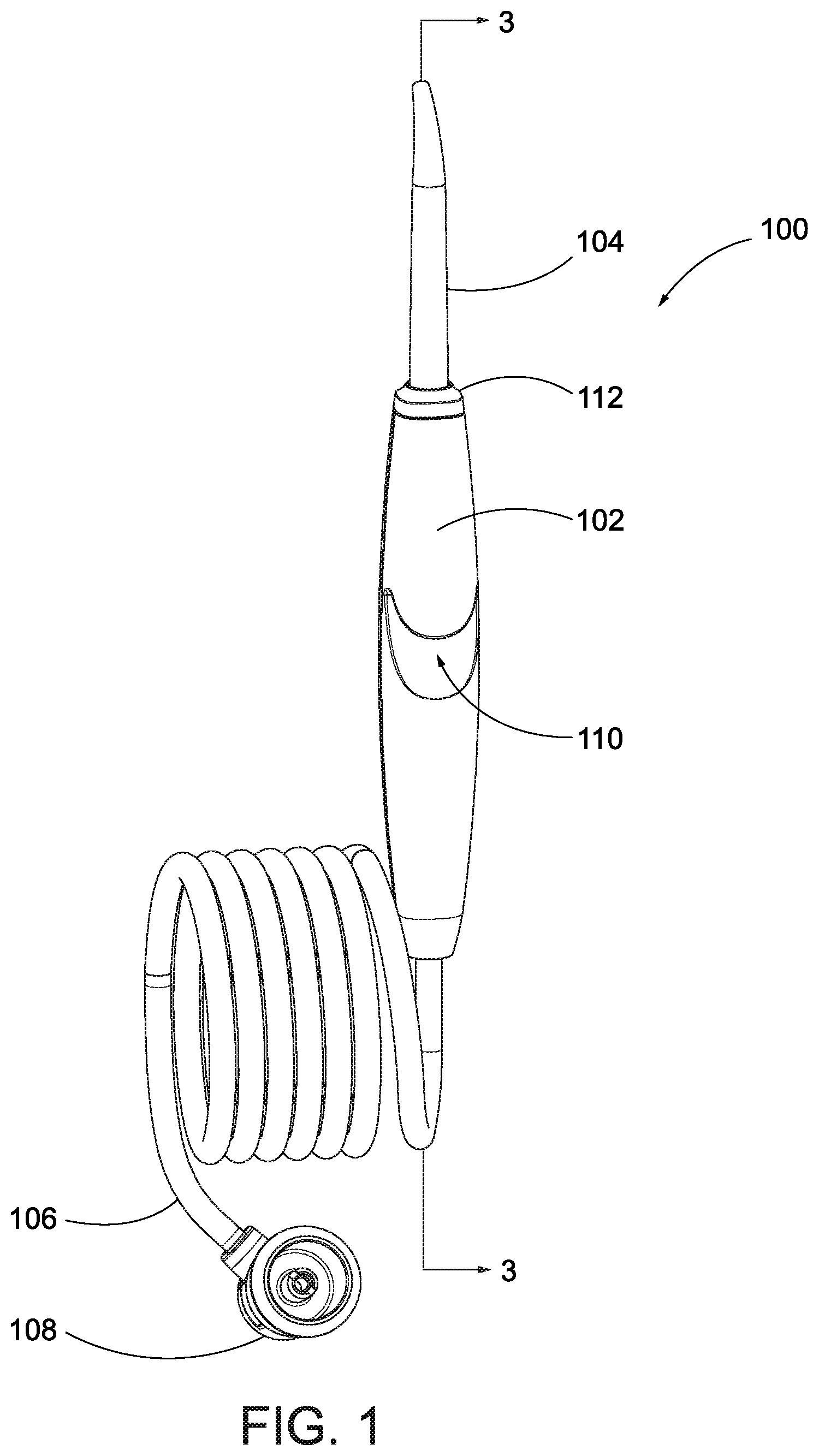
FIG. 1 is a rear elevation view of a handle for an oral irrigator connected to a hose for a base unit.
FIG. 2 is an exploded view of the handle of FIG. 1.
FIG. 3 is a cross-section view of the handle of FIG. 1 taken along line 3-3 in FIG. 1.
FIG. 4A is a front elevation view of a first shell of a handle housing for the handle of FIG. 1.
FIG. 4B is a front elevation view of a second shell of the handle housing.
FIG. 5 is an enlarged view of FIG. 3 illustrating a tip connector of the handle.
FIG. 6 is a front elevation view of a tip fitting for the handle of FIG. 1.
FIG. 7 is an enlarged view of FIG. 3 illustrating a swivel assembly of the handle.
FIG. 8 is a front elevation view of a stationary connector of the swivel assembly.
FIG. 9 is a front elevation view of a swivel connector of the swivel assembly.
FIG. 10 is a front elevation view of another example of a handle with the swivel assembly with a first shell of the handle hidden to illustrate the internal components.
FIG. 11 is an enlarged cross-section view of the handle of FIG. 10 taken along a line similar to line 3-3 in FIG. 1.
FIG. 12 is a perspective view of an oral irrigator including the handle of FIG. 1.
DETAILED DESCRIPTION
The present disclosure is generally related to a swivel assembly for a handle for an oral irrigator. The swivel assembly allows the hose to rotate 360 degrees relative to the handle such that, as a user moves the handle in various directions and/or rotates the handle, the hose can spin within the handle, reducing the chance that the hose will become tangled, bent, or the like. In other words, the swivel assembly prevents rotational movement of either the handle or the hose from being transmitted to the other, such that rotation of the handle does not affect the position of the hose. The swivel assembly can be positioned within the handle housing or outside the housing (e.g., beneath the handle) to allow the relative motion of the hose to the handle.
With reference to FIGS. 1 and 2, the handle 100 includes a main body or housing 102 and a tip 104 connected to the housing 102. A hose 106 connects the handle 100 to a fluid source, and optionally may include a connector 108 for connecting the hose 106 to the fluid source (e.g., connecting the hose 106 to a base unit). A swivel assembly 118 is connected to the housing 102 and the hose 106 and allows the hose 106 and the housing 102 to rotate relative to one another.
The housing 102 forms a main body for the handle 100 and can be configured to be easily grasped by the hand of a user. In these embodiments, the housing 102 may form a generally elongated tube. Additionally, the housing 102 may be configured to connect to a storage component of an oral irrigator base, such as a C-clamp, cutout, or the like. In one embodiment, the housing 102 includes an integrated hanging feature 110. In this embodiment, the hanging feature 110 is defined as an angled groove or slot extending at an angle into the housing 102. FIG. 3 is a cross section of the handle 100. As shown in FIG. 3, the hanging feature 110 is an upwardly angled groove that begins at approximately a mid-section of the housing 102 and is angled at approximately a 45 degree angle toward the tip 104. The angle of the hanging feature 110 can be varied depending on a desired storage angle of the tip relative to the base. (See FIG. 12 illustrating the angle of the handle 100 in the storage position.)
In some embodiments, the housing 102 may be formed as two shells 112, 114 that connect together. FIGS. 4A and 4B illustrate elevation views of the handle shells. With reference to FIGS. 4A, a first shell 112 defines a housing cavity 142 that extends laterally along a length of the shell 112. The top end of the first shell 112 includes a cutout defining a tip aperture 140 that extends into the cavity 142. An interior wall 150 of the first shell 112 may include one or more support features 148 defined integrally therewith. The support features 148 are configured to support various components of the swivel assembly 118 and may be modified as desired to support the components. In one embodiment, the support features 148 include upper and lower support ledges 152a, 152b formed as circular steps that extend outward from the interior surface 150 and a groove 154 defined as a slot extending into the interior surface 150 and recessed therefrom. In one embodiment, the groove 154 defines the upper support ledge 152a. In other embodiments, the upper support ledge 152a may be defined in other manners. One or more angled features 156 may be formed between the ledges 152a, 152b as frustum-shaped or tapered slots that extend into the interior surface 150. The angled features 156 may be configured to receive components of the swivel assembly 118, as well as reduce the weight of the housing 102.
A bottom end of the first shell 112 tapers toward the terminal end. The interior surface 150 angles inward to form a tapered wall 146 having an initial taper that flares out at an inflection point 158 to form the hose aperture 144.
With reference to FIG. 4B, the second shell 114 may be substantially a mirror image of the first shell 112 and configured to mate therewith. In one embodiment, however, the second shell 114 includes the hanging feature 110 and thus an upper portion of the interior surface 160 forms an angled wall. The ledges 162a, 162b, the groove 162, the angled features 166, the tapered wall 136, and the hose aperture 134 are substantially the same as those in the first shell 112.
The handle 100 may also include a tip fitting 120 for securing the tip 104 to the housing 102. FIG. 5 is an enlarged view of the cross-section view of FIG. 3. FIG. 6 is a front elevation view of the tip fitting 120. With reference to FIGS. 5 and 6, the tip fitting 120 includes a main body 172 with a barb 170 extending downward therefrom. The main body 172 may be a hollow member, such as a cylindrical tube that defines an interior cavity 174 sized to receive the bottom end of the tip 104. The barb 170 is also hollow defining a fluid path that extends from the interior cavity 174 through the barb 170. In use, the barb 170 acts as an inlet into the interior cavity 174 such that when the tip 104 is positioned within the cavity 174, the barb 170 is in fluid communication therewith.
The tip fitting 120 may also include alignment flanges 176a, 176b that extend from the outer surface of the main body 172. In one embodiment, the alignment flanges 176a, 176b are defined as substantially rectangular protrusions with curved corners. The alignment flanges 176a, 176b engage with of the housing 102 and fit between ribs in the interior surfaces 150, 160 to secure the fitting 120 in position within the housing 102.
FIG. 7 is an enlarged view of FIG. 3 illustrating the swivel assembly 118. With reference to FIGS. 2, 3, and 7, the swivel assembly 118 includes a stationary connector 124, a swivel connector 126, and a sealing element 128. Each of the components is discussed in turn, below.
The stationary connector 124 fluidly connects the swivel assembly 118 to the tube 116 and tip 104. The stationary connector 124 is configured to engage the interior surfaces 150, 160 of the housing 102 to remain stationary relative thereto. FIG. 8 is a front elevation view of the stationary connector 124. With reference to FIGS. 7 and 8, the stationary connector 124 includes a reception cavity 188 defined by an outer wall 186. A securing feature 180 extends from the top end of the outer wall 186. In one embodiment, the outer wall 186 is substantially cylindrical and the securing feature 180 is substantially rectangular or square shaped and the securing feature 180 extends past the outer perimeter of the outer wall 186 to define a lip for the stationary connector 124.
A connection barb 182 extends from the top surface of the securing feature 180. The connection barb 182 may include one or more gripping elements 192 to enhance the connection of the tube 116 to the barb 182. The barb 182 defines a fluid channel 190 therethrough in fluid communication with the reception cavity 188 and acts as an outlet port for fluid flowing through the reception cavity 188. The fluid channel 190 is in fluid communication with the reception cavity 188 defined by the outer wall 186.
The stationary connector 124 may also include one or more component ledges 184 or steps defined on an interior surface of the outer wall 186. The component ledges 184 are used to seat components such as the sealing member 128 or the like.
With reference again to FIG. 7, the swivel connector 126 is configured to be received within and rotate relative to the stationary connector 124. In this manner, the swivel connector 126 does not translate rotational movement to the handle, since it can rotate relative to the handle. FIG. 9 is a front elevation view of the swivel connector 126. With reference to FIGS. 7 and 9, the swivel connector 126 defines a flow passage 206 that extends along the entire longitudinal length of the swivel connector 126. A bottom end of the swivel connector 126 includes a barb 202 that defines a portion of the flow passage 206 and has one or more gripping components 204 that enhance the connection between the swivel connector 126 and the hose 106. The barb 202 acts as an inlet port for fluid flow through the handle 100 from the hose 106.
In one embodiment, the main body 200 of the swivel connector 126 may be formed as a series of stacked concentric disks. For example, the top disk 210 has the smallest radius of the stack and the middle disk 209 has a diameter between those of the top disk 210 and the bottom disk 208. The axial length or thickness of each of the disks 208, 209, 210 increases between each disk, with the bottom disk 208 having the shortest thickness, the middle disk 209 having a thickness between the top and bottom disks 208, 210, and the top disk 210 having the largest thickness. As should be appreciated, the configuration of the main body 200, and specifically the disks 208, 209, 210, is variable based on the configuration of the stationary connector 124.
With reference to FIGS. 2 and 3, the handle 100 may include a tube 116 for fluidly connecting the swivel assembly 118 to the tip fitting 120. The tube 116 in some embodiments is flexible and configured to bend around the interior surface 160 of the shell 114 forming the hanging feature 110.
The assembly of the handle 100 will now be discussed with reference to FIGS. 2, 3, 5, and 7. The tip fitting 120 is inserted into a top end of one of the shells 112, 114 and the jet tip 104 is inserted into the interior cavity 174 of the main body 172. The flow path of the jet tip 104 is aligned with and fluidly connected to the flow path defined through the barb 107. A first end of the tube 116 is connected to barb 170 and the second end of the tube 116 I received around the barb 182 of the stationary connector 124.
With reference to FIGS. 4A, 4B, and 7, the stationary connector 124 is inserted into one of the shells 112, 114. For example, the stationary connector 124 may be first inserted into the first shell 112 with the securing feature 180 received in the groove 154 beneath the first ledge 152a. The sealing member 128, which may be a seal cup, O-ring, or other sealing element, may be positioned around the top disk 210 of the swivel connector 126 and then the top disk 210 of the swivel connector 126 is inserted into the reception cavity 188 of the stationary fitting 124. In this embodiment, the middle disk 208 engages with one of the steps within the outer wall 186 of the stationary connector 124 and the bottom disk 208 extends beneath and engages the bottom edge 187 of the stationary connector 124. The bottom disk 208 of the swivel connector 126 seats on the top surface of the bottom ledge 152b of the shell 112. The top end of the hose 106 is then received around the barb 202 of the swivel connector 126, fluidly connecting the hose 106, the swivel connector 126, the stationary fitting 124, and the tube 116 together.
With the internal components connected together, the opposite shell 112, 114, e.g., the second shell 114 is connected to the first shell 112. The ledges 162a, 162b are aligned with the swivel assembly 118 such that they bookend the securing feature 180 of the stationary connector 124 and the bottom disk 208 of the swivel connector 126. In other words, once the shells are connected together the ledges 152a, 152b, 162a, 162b of the two shells 112, 114 clamp around the swivel assembly 118 to prevent longitudinal movement of the assembly, the stationary connector, or the swivel connector relative to the housing 102. The shells 112, 114 are then secured together, e.g., by ultrasonic welding, with adhesive, press fit, fasteners, or the like. The tip collar 111 may be connected around the outer surface of the tip 104 and seat on the top end of the housing 102 of the handle 104.
In some embodiments, once the tip 104 is connected to the housing 102, the tip 104 may not rotate relative thereto or be ejectable relative thereto. For example, the alignment features 176a, 176b of the tip fitting 120 may key to ribs on the interior surfaces 150, 160 of the housing 102 to prevent rotation and the tip 104, which is press fit into the fitting 120 may be secured correspondingly. However, in other embodiments, conventional tip fitting components and/or eject mechanisms may be used to allow the tip 104 to rotate relative to the housing 102 and allow the tip 104 to be removed from the housing 102.
With reference to FIG. 12, fluids, such as water, that are pumped by a pump 402 from a countertop oral irrigator unit 400 flow through the hose 106, into the fluid passage 206 within the swivel connector 126, into the reception cavity 188 of the stationary connector 124, into the fluid passage 190 within the barb 182 and into the tube 116. From the tube 116, fluid flows into the fluid passage in the barb 170 of the tip fitting 120 and into the tip 104 which is received therein.
During use, as the user moves the handle 100 into different angles and positions to access different areas of his or her mouth, the hose 106 can rotate freely relative to the handle to maintain a desired orientation and be free from tangles and undesired bends or creases. In particular, during use, as the user moves the handle 100 to different orientations, the hose 106, which typically is anchored to a base unit, can rotate at its connection to the handle as the swivel connector 126 rotates within and relative to the stationary connector 124. In these embodiments, the materials of the stationary connector 124 and the swivel connector 126 are selected to be low-friction so as to introduce minimal to no drag.
Alternative Embodiment
In some embodiments, the tube 116 and the stationary connector 124 may be integrally formed. FIGS. 10 and 11 illustrate views of another embodiment of the handle 100. With reference to FIGS. 10 and 11, in this embodiment, the swivel assembly 300 includes a stationary connector 324, a swivel connector 326, and a sealing member 328, each of which may be substantially the same as the corresponding components in the swivel assembly 118. However, in this embodiment, the stationary connector 324 includes an extended tube 330 rather than a barb at its top end. The tube 330 is formed integrally with the main body of the connector 324 and is fluidly connected the reception cavity 338 formed by the outer wall 340.
In these embodiments, the tube 330 may connect directly to a tip fitting to fluidly connect to the tip 104. Additionally, as mentioned above, in this embodiment, the handle may include a pause switch assembly and tip ejection assembly. Examples of these assemblies are described in U.S. patent application Ser. No. 14/555,339 filed on 26 Nov. 2014 entitled "Oral Irrigator with Slide Pause Switch," which is hereby incorporated by reference herein in its entirety.
All directional references (e.g., upper, lower, upward, downward, left, right, leftward, rightward, top, bottom, above, below, vertical, horizontal, clockwise, and counterclockwise) are only used for identification purposes to aid the reader's understanding of the embodiments of the present invention, and do not create limitations, particularly as to the position, orientation, or use of the invention unless specifically set forth in the claims. Joinder references (e.g., attached, coupled, connected, joined, and the like) are to be construed broadly and may include intermediate members between a connection of elements and relative movement between elements. As such, joinder references do not necessarily infer that two elements are directly connected and in fixed relation to each other. The exemplary drawings are for purposes of illustration only and the dimensions, positions, order and relative sizes reflected in the drawings attached hereto may vary.
The above specification, examples and data provide a complete description of the structure and use of exemplary embodiments of the invention as defined in the claims. Although various embodiments of the claimed invention have been described above with a certain degree of particularity, or with reference to one or more individual embodiments, those skilled in the art could make numerous alterations to the disclosed embodiments without departing from the spirit or scope of the claimed invention. Other embodiments are therefore contemplated. It is intended that all matter contained in the above description and shown in the accompanying drawings shall be interpreted as illustrative only of particular embodiments and not limiting. Changes in detail or structure may be made without departing from the basic elements of the invention as defined in the following claims.
* * * * *
References
-
just4teeth.com/product/Panasonic/Panasonic_Portable_Irrigator.htm
-
videodirectstore.com/store/merchant.mv?Screen=PROD&Product_Code=EW1
-
products.consumerguide.com/cp/family/review/index.cfm/id/18742
-
racekarteng.com/images/walbroparts.gifand
-
muller.net/mullermachine/docs/walbro1.html
-
insightsbyapril.com/2012/03/waterpik-natural-remedy-for-sinus.html
-
waterpik.com/about-us
-
dentalhoo.com/waterpik-wp350.asp
-
allexpress.com/...e-Oral-Care-Product-Nasal-Irrigator-Tooth-Flosser-Water/1525541997.html?aff_platform=aaf&cpt=1490913714609&sk=yfAeyJa&aff_trace_key=c5a300c4f02e46d08c042f5292e1762f-1490913714609-07517-yfAeyJa
-
briteleafs.com/product6.html
-
aliexpress.com/item/Cordless-Water-Floss-Portable-Oral-Irrigator-Dental-Water-Flosser-Waterpic-Whatpick-Dental-Water-Pic-Whater-Pick/32769416341.html?spm=2114.40010308.4.75.Owuzfj
D00000
D00001
D00002
D00003
D00004
D00005
D00006
D00007
D00008
D00009
D00010
D00011
D00012

D00013

XML
uspto.report is an independent third-party trademark research tool that is not affiliated, endorsed, or sponsored by the United States Patent and Trademark Office (USPTO) or any other governmental organization. The information provided by uspto.report is based on publicly available data at the time of writing and is intended for informational purposes only.
While we strive to provide accurate and up-to-date information, we do not guarantee the accuracy, completeness, reliability, or suitability of the information displayed on this site. The use of this site is at your own risk. Any reliance you place on such information is therefore strictly at your own risk.
All official trademark data, including owner information, should be verified by visiting the official USPTO website at www.uspto.gov. This site is not intended to replace professional legal advice and should not be used as a substitute for consulting with a legal professional who is knowledgeable about trademark law.