Battery powered surgical instrument
Monson , et al. Sept
U.S. patent number 10,779,876 [Application Number 15/352,408] was granted by the patent office on 2020-09-22 for battery powered surgical instrument. This patent grant is currently assigned to Ethicon LLC. The grantee listed for this patent is Ethicon LLC. Invention is credited to John Hefin Bowen Evans, Alan E. Green, Gordon J. Leather, Robin M. Lee, Gavin M. Monson, Paulo Alexandre da Torre Pinheiro, Paul C. Roberts, David I. Ruddenklau, David A. Snowdon, David J. Stocks, Clive Styler, Gregory A. Trees.


View All Diagrams
| United States Patent | 10,779,876 |
| Monson , et al. | September 22, 2020 |
Battery powered surgical instrument
Abstract
A medical instrument is disclosed. The medical instrument includes at least one electrical contact element, a battery, a radio frequency (RF) generation circuit coupled to and operated by the battery and operable to generate an RF drive signal and to provide the RF drive signal to the at least one electrical contact, and a battery discharge circuit coupled to the battery. A processor is coupled to the battery discharge circuit and a memory is coupled to the processor. The memory stores machine executable instructions that when executed cause the processor to monitor activation of the RF generation circuit and disable the RF generation circuit when the RF drive signal is fired a predetermined number of times. The medical instrument may include an activation switch and/or a disposal switch supported by the housing.
| Inventors: | Monson; Gavin M. (Oxford, OH), Trees; Gregory A. (Loveland, OH), Leather; Gordon J. (White Roding, GB), Stocks; David J. (Royston, GB), Snowdon; David A. (Saffron Walden, GB), Evans; John Hefin Bowen (Boncath, GB), Ruddenklau; David I. (Christchurch, NZ), Green; Alan E. (Fulbourn, GB), Lee; Robin M. (Linton, GB), Roberts; Paul C. (Cambridge, GB), Pinheiro; Paulo Alexandre da Torre (Bishop's Stortford, GB), Styler; Clive (Cambridge, GB) | ||||||||||
|---|---|---|---|---|---|---|---|---|---|---|---|
| Applicant: |
|
||||||||||
| Assignee: | Ethicon LLC (Guaynabo,
PR) |
||||||||||
| Family ID: | 1000005067011 | ||||||||||
| Appl. No.: | 15/352,408 | ||||||||||
| Filed: | November 15, 2016 |
Prior Publication Data
| Document Identifier | Publication Date | |
|---|---|---|
| US 20170056097 A1 | Mar 2, 2017 | |
Related U.S. Patent Documents
| Application Number | Filing Date | Patent Number | Issue Date | ||
|---|---|---|---|---|---|
| 13658786 | Oct 23, 2012 | ||||
| 61550768 | Oct 24, 2011 | ||||
| Current U.S. Class: | 1/1 |
| Current CPC Class: | F16B 2/20 (20130101); A61B 18/1233 (20130101); H02J 7/00 (20130101); A61B 18/18 (20130101); A61B 18/1445 (20130101); H02J 7/0063 (20130101); A61B 18/1206 (20130101); A61B 2018/00732 (20130101); A61B 2018/1286 (20130101); A61B 2018/00827 (20130101); Y10T 74/20666 (20150115); A61B 2018/00642 (20130101); A61B 2018/00702 (20130101); A61B 2018/00595 (20130101); A61B 2018/00916 (20130101); A61B 2018/1455 (20130101); A61B 2018/00875 (20130101); A61B 2018/00726 (20130101); A61B 2017/00115 (20130101); A61B 2018/00196 (20130101); A61B 2018/00922 (20130101); A61B 2018/1226 (20130101); A61B 2018/00892 (20130101); A61B 2018/00767 (20130101); A61B 2018/0072 (20130101) |
| Current International Class: | A61B 18/12 (20060101); H02J 7/00 (20060101); A61B 18/14 (20060101); F16B 2/20 (20060101); A61B 18/18 (20060101); A61B 18/00 (20060101); A61B 17/00 (20060101) |
References Cited [Referenced By]
U.S. Patent Documents
| 2366274 | January 1945 | Luth et al. |
| 2458152 | January 1949 | Eakins |
| 2510693 | June 1950 | Green |
| 2736960 | March 1956 | Armstrong |
| 2849788 | September 1958 | Creek |
| 2867039 | January 1959 | Zach |
| 3015961 | January 1962 | Roney |
| 3043309 | July 1962 | McCarthy |
| 3166971 | January 1965 | Stoecker |
| 3358676 | December 1967 | Frei et al. |
| 3525912 | August 1970 | Wallin |
| 3526219 | September 1970 | Balamuth |
| 3580841 | May 1971 | Cadotte et al. |
| 3614484 | October 1971 | Shoh |
| 3636943 | January 1972 | Balamuth |
| 3703651 | November 1972 | Blowers |
| 3710399 | January 1973 | Hurst |
| 3776238 | December 1973 | Peyman et al. |
| 3777760 | December 1973 | Essner |
| 3805787 | April 1974 | Banko |
| 3862630 | January 1975 | Balamuth |
| 3900823 | August 1975 | Sokal et al. |
| 3906217 | September 1975 | Lackore |
| 3918442 | November 1975 | Nikolaev et al. |
| 3946738 | March 1976 | Newton et al. |
| 3955859 | May 1976 | Stella et al. |
| 3956826 | May 1976 | Perdreaux, Jr. |
| 3988535 | October 1976 | Hickman et al. |
| 4005714 | February 1977 | Hiltebrandt |
| 4034762 | July 1977 | Cosens et al. |
| 4047136 | September 1977 | Satto |
| 4058126 | November 1977 | Leveen |
| 4063561 | December 1977 | McKenna |
| 4099192 | July 1978 | Aizawa et al. |
| 4156187 | May 1979 | Murry et al. |
| 4188927 | February 1980 | Harris |
| 4200106 | April 1980 | Douvas et al. |
| 4203430 | May 1980 | Takahashi |
| 4220154 | September 1980 | Semm |
| 4237441 | December 1980 | van Konynenburg et al. |
| 4278077 | July 1981 | Mizumoto |
| 4281785 | August 1981 | Brooks |
| 4304987 | December 1981 | van Konynenburg |
| 4314559 | February 1982 | Allen |
| 4384584 | May 1983 | Chen |
| 4445063 | April 1984 | Smith |
| 4463759 | August 1984 | Garito et al. |
| 4491132 | January 1985 | Aikins |
| 4492231 | January 1985 | Auth |
| 4535773 | August 1985 | Yoon |
| 4545926 | October 1985 | Fouts, Jr. et al. |
| 4550870 | November 1985 | Krumme et al. |
| 4582236 | April 1986 | Hirose |
| 4585282 | April 1986 | Bosley |
| 4597390 | July 1986 | Mulhollan et al. |
| 4617927 | October 1986 | Manes |
| 4633874 | January 1987 | Chow et al. |
| 4634420 | January 1987 | Spinosa et al. |
| 4640279 | February 1987 | Beard |
| 4655746 | April 1987 | Daniels et al. |
| 4671287 | June 1987 | Fiddian-Green |
| 4708127 | November 1987 | Abdelghani |
| 4735603 | April 1988 | Goodson et al. |
| 4761871 | August 1988 | O'Connor et al. |
| 4777951 | October 1988 | Cribier et al. |
| 4797803 | January 1989 | Carroll |
| 4798588 | January 1989 | Aillon |
| 4802461 | February 1989 | Cho |
| 4803506 | February 1989 | Diehl et al. |
| 4830462 | May 1989 | Karny et al. |
| 4832683 | May 1989 | Idemoto et al. |
| 4838853 | June 1989 | Parisi |
| 4849133 | July 1989 | Yoshida et al. |
| 4850354 | July 1989 | McGurk-Burleson et al. |
| 4860745 | August 1989 | Farin et al. |
| 4865159 | September 1989 | Jamison |
| 4878493 | November 1989 | Pasternak et al. |
| 4880015 | November 1989 | Nierman |
| 4896009 | January 1990 | Pawlowski |
| 4910389 | March 1990 | Sherman et al. |
| 4910633 | March 1990 | Quinn |
| 4911148 | March 1990 | Sosnowski et al. |
| 4919129 | April 1990 | Weber, Jr. et al. |
| 4920978 | May 1990 | Colvin |
| 4922902 | May 1990 | Wuchinich et al. |
| 4936842 | June 1990 | D'Amelio et al. |
| 4961738 | October 1990 | Mackin |
| 4967670 | November 1990 | Morishita et al. |
| 4981756 | January 1991 | Rhandhawa |
| 5007919 | April 1991 | Silva et al. |
| 5019075 | May 1991 | Spears et al. |
| 5020514 | June 1991 | Heckele |
| 5026387 | June 1991 | Thomas |
| 5061269 | October 1991 | Muller |
| 5093754 | March 1992 | Kawashima |
| 5099216 | March 1992 | Pelrine |
| 5099840 | March 1992 | Goble et al. |
| 5104025 | April 1992 | Main et al. |
| 5106538 | April 1992 | Barma et al. |
| 5108383 | April 1992 | White |
| 5112300 | May 1992 | Ureche |
| 5123903 | June 1992 | Quaid et al. |
| 5150102 | September 1992 | Takashima |
| 5150272 | September 1992 | Danley et al. |
| 5156633 | October 1992 | Smith |
| 5160334 | November 1992 | Billings et al. |
| 5162044 | November 1992 | Gahn et al. |
| 5167725 | December 1992 | Clark et al. |
| D332660 | January 1993 | Rawson et al. |
| 5176695 | January 1993 | Dulebohn |
| 5184605 | February 1993 | Grzeszykowski |
| 5188102 | February 1993 | Idemoto et al. |
| 5190541 | March 1993 | Abele et al. |
| 5196007 | March 1993 | Ellman et al. |
| 5205459 | April 1993 | Brinkerhoff et al. |
| 5205817 | April 1993 | Idemoto et al. |
| 5209719 | May 1993 | Baruch et al. |
| 5213569 | May 1993 | Davis |
| 5217460 | June 1993 | Knoepfler |
| 5221282 | June 1993 | Wuchinich |
| 5226910 | July 1993 | Kajiyama et al. |
| 5234428 | August 1993 | Kaufman |
| 5241236 | August 1993 | Sasaki et al. |
| 5253647 | October 1993 | Takahashi et al. |
| 5254130 | October 1993 | Poncet et al. |
| 5257988 | November 1993 | L'Esperance, Jr. |
| 5258004 | November 1993 | Bales et al. |
| 5258006 | November 1993 | Rydell et al. |
| 5261922 | November 1993 | Hood |
| 5263957 | November 1993 | Davison |
| 5267091 | November 1993 | Chen |
| 5282800 | February 1994 | Foshee et al. |
| 5285945 | February 1994 | Brinkerhoff et al. |
| 5290286 | March 1994 | Parins |
| 5293863 | March 1994 | Zhu et al. |
| 5304115 | April 1994 | Pflueger et al. |
| D347474 | May 1994 | Olson |
| 5309927 | May 1994 | Welch |
| 5312023 | May 1994 | Green et al. |
| 5313306 | May 1994 | Kuban et al. |
| 5318563 | June 1994 | Malis et al. |
| 5318564 | June 1994 | Eggers |
| 5318565 | June 1994 | Kuriloff et al. |
| 5318570 | June 1994 | Hood et al. |
| 5318589 | June 1994 | Lichtman |
| 5322055 | June 1994 | Davison et al. |
| 5324260 | June 1994 | O'Neill et al. |
| 5324299 | June 1994 | Davison et al. |
| 5326013 | July 1994 | Green et al. |
| 5330471 | July 1994 | Eggers |
| 5330502 | July 1994 | Hassler et al. |
| 5333624 | August 1994 | Tovey |
| 5339723 | August 1994 | Huitema |
| 5342359 | August 1994 | Rydell |
| 5344420 | September 1994 | Hilal et al. |
| 5346502 | September 1994 | Estabrook et al. |
| 5352219 | October 1994 | Reddy |
| 5359992 | November 1994 | Hori et al. |
| 5361583 | November 1994 | Huitema |
| 5366466 | November 1994 | Christian et al. |
| 5370640 | December 1994 | Kolff |
| D354564 | January 1995 | Medema |
| 5381067 | January 1995 | Greenstein et al. |
| 5383874 | January 1995 | Jackson et al. |
| 5387207 | February 1995 | Dyer et al. |
| 5389098 | February 1995 | Tsuruta et al. |
| 5395033 | March 1995 | Byrne et al. |
| 5395312 | March 1995 | Desai |
| 5395331 | March 1995 | O'Neill et al. |
| 5395363 | March 1995 | Billings et al. |
| 5395364 | March 1995 | Anderhub et al. |
| 5396266 | March 1995 | Brimhall |
| 5396900 | March 1995 | Slater et al. |
| 5403312 | April 1995 | Yates et al. |
| 5409483 | April 1995 | Campbell et al. |
| D358887 | May 1995 | Feinberg |
| 5411481 | May 1995 | Allen et al. |
| 5413575 | May 1995 | Haenggi |
| 5417709 | May 1995 | Slater |
| 5419761 | May 1995 | Narayanan et al. |
| 5421829 | June 1995 | Olichney et al. |
| 5428504 | June 1995 | Bhatla |
| 5429131 | July 1995 | Scheinman et al. |
| 5431640 | July 1995 | Gabriel |
| 5443463 | August 1995 | Stern et al. |
| 5445615 | August 1995 | Yoon |
| 5445638 | August 1995 | Rydell et al. |
| 5449370 | September 1995 | Vaitekunas |
| 5451227 | September 1995 | Michaelson |
| 5456684 | October 1995 | Schmidt et al. |
| 5458598 | October 1995 | Feinberg et al. |
| 5462604 | October 1995 | Shibano et al. |
| 5465895 | November 1995 | Knodel et al. |
| 5472443 | December 1995 | Cordis et al. |
| 5476479 | December 1995 | Green et al. |
| 5477788 | December 1995 | Morishita |
| 5478003 | December 1995 | Green et al. |
| 5480409 | January 1996 | Riza |
| 5483501 | January 1996 | Park et al. |
| 5484436 | January 1996 | Eggers et al. |
| 5486162 | January 1996 | Brumbach |
| 5486189 | January 1996 | Mudry et al. |
| 5489256 | February 1996 | Adair |
| 5496317 | March 1996 | Goble et al. |
| 5500216 | March 1996 | Julian et al. |
| 5501654 | March 1996 | Failla et al. |
| 5504650 | April 1996 | Katsui et al. |
| 5505693 | April 1996 | Mackool |
| 5509922 | April 1996 | Aranyi et al. |
| 5511556 | April 1996 | DeSantis |
| 5520704 | May 1996 | Castro et al. |
| 5522839 | June 1996 | Pilling |
| 5531744 | July 1996 | Nardella et al. |
| 5540648 | July 1996 | Yoon |
| 5540681 | July 1996 | Strul et al. |
| 5542916 | August 1996 | Hirsch et al. |
| 5542938 | August 1996 | Avellanet et al. |
| 5558671 | September 1996 | Yates |
| 5562609 | October 1996 | Brumbach |
| 5562610 | October 1996 | Brumbach |
| 5562657 | October 1996 | Griffin |
| 5563179 | October 1996 | Stone et al. |
| 5569164 | October 1996 | Lurz |
| 5571121 | November 1996 | Heifetz |
| 5573534 | November 1996 | Stone |
| 5584830 | December 1996 | Ladd |
| 5599350 | February 1997 | Schulze et al. |
| 5601601 | February 1997 | Tal et al. |
| 5604531 | February 1997 | Iddan et al. |
| 5607436 | March 1997 | Pratt et al. |
| 5607450 | March 1997 | Zvenyatsky et al. |
| 5611813 | March 1997 | Lichtman |
| 5618307 | April 1997 | Donlon et al. |
| 5618492 | April 1997 | Auten et al. |
| 5624452 | April 1997 | Yates |
| 5626578 | May 1997 | Tihon |
| 5628760 | May 1997 | Knoepfler |
| 5630420 | May 1997 | Vaitekunas |
| 5632432 | May 1997 | Schulze et al. |
| D381077 | July 1997 | Hunt |
| 5643175 | July 1997 | Adair |
| 5645065 | July 1997 | Shapiro et al. |
| 5647871 | July 1997 | Levine et al. |
| 5651780 | July 1997 | Jackson et al. |
| 5653677 | August 1997 | Okada et al. |
| 5653713 | August 1997 | Michelson |
| 5657697 | August 1997 | Murai |
| 5658281 | August 1997 | Heard |
| 5662667 | September 1997 | Knodel |
| 5665085 | September 1997 | Nardella |
| 5665100 | September 1997 | Yoon |
| 5669922 | September 1997 | Hood |
| 5674219 | October 1997 | Monson et al. |
| 5674220 | October 1997 | Fox et al. |
| 5674235 | October 1997 | Parisi |
| 5681260 | October 1997 | Ueda et al. |
| 5688270 | November 1997 | Yates et al. |
| 5690269 | November 1997 | Bolanos et al. |
| 5693051 | December 1997 | Schulze et al. |
| 5694936 | December 1997 | Fujimoto et al. |
| 5700243 | December 1997 | Narciso, Jr. |
| 5700261 | December 1997 | Brinkerhoff |
| 5704900 | January 1998 | Dobrovolny et al. |
| 5709680 | January 1998 | Yates et al. |
| 5711472 | January 1998 | Bryan |
| 5713896 | February 1998 | Nardella |
| 5716366 | February 1998 | Yates |
| 5720742 | February 1998 | Zacharias |
| 5720744 | February 1998 | Eggleston et al. |
| 5722326 | March 1998 | Post |
| 5722426 | March 1998 | Kolff |
| 5732636 | March 1998 | Wang et al. |
| 5733074 | March 1998 | Stock et al. |
| 5735848 | April 1998 | Yates et al. |
| 5738652 | April 1998 | Boyd et al. |
| 5741226 | April 1998 | Strukel et al. |
| 5741305 | April 1998 | Vincent |
| 5743906 | April 1998 | Parins et al. |
| 5752973 | May 1998 | Kieturakis |
| 5755717 | May 1998 | Yates et al. |
| 5762255 | June 1998 | Chrisman et al. |
| 5776130 | July 1998 | Buysse et al. |
| 5779701 | July 1998 | McBrayer et al. |
| 5782834 | July 1998 | Lucey et al. |
| 5792135 | August 1998 | Madhani et al. |
| 5792138 | August 1998 | Shipp |
| 5796188 | August 1998 | Bays |
| 5797941 | August 1998 | Schulze et al. |
| 5800432 | September 1998 | Swanson |
| 5800449 | September 1998 | Wales |
| 5805140 | September 1998 | Rosenberg et al. |
| 5807393 | September 1998 | Williamson, IV et al. |
| 5810718 | September 1998 | Akiba et al. |
| 5810811 | September 1998 | Yates et al. |
| 5810859 | September 1998 | DiMatteo et al. |
| 5817033 | October 1998 | DeSantis et al. |
| 5817084 | October 1998 | Jensen |
| 5817093 | October 1998 | Williamson, IV et al. |
| 5827323 | October 1998 | Klieman et al. |
| 5828160 | October 1998 | Sugishita |
| 5836867 | November 1998 | Speier et al. |
| 5836909 | November 1998 | Cosmescu |
| 5836943 | November 1998 | Miller, III |
| 5836990 | November 1998 | Li |
| 5843109 | December 1998 | Mehta et al. |
| 5853412 | December 1998 | Mayenberger |
| 5876401 | March 1999 | Schulze et al. |
| 5878193 | March 1999 | Wang et al. |
| 5879364 | March 1999 | Bromfield et al. |
| 5880668 | March 1999 | Hall |
| 5883454 | March 1999 | Hones et al. |
| 5887018 | March 1999 | Bayazitoglu et al. |
| 5891142 | April 1999 | Eggers et al. |
| 5893835 | April 1999 | Witt et al. |
| 5897569 | April 1999 | Kellogg et al. |
| 5902239 | May 1999 | Buurman |
| 5904147 | May 1999 | Conlan et al. |
| 5906579 | May 1999 | Vander Salm et al. |
| 5906625 | May 1999 | Bito et al. |
| 5910129 | June 1999 | Koblish et al. |
| 5921956 | July 1999 | Grinberg et al. |
| 5929846 | July 1999 | Rosenberg et al. |
| 5935143 | August 1999 | Hood |
| 5935144 | August 1999 | Estabrook |
| 5938633 | August 1999 | Beaupre |
| 5944298 | August 1999 | Koike |
| 5944718 | August 1999 | Austin et al. |
| 5944737 | August 1999 | Tsonton et al. |
| 5954736 | September 1999 | Bishop et al. |
| 5954746 | September 1999 | Holthaus et al. |
| 5957849 | September 1999 | Munro |
| 5957882 | September 1999 | Nita et al. |
| 5957943 | September 1999 | Vaitekunas |
| 5968007 | October 1999 | Simon et al. |
| 5968060 | October 1999 | Kellogg |
| D416089 | November 1999 | Barton et al. |
| 5984938 | November 1999 | Yoon |
| 5989182 | November 1999 | Hori et al. |
| 5989274 | November 1999 | Davison et al. |
| 5989275 | November 1999 | Estabrook et al. |
| 5993972 | November 1999 | Reich et al. |
| 6003517 | December 1999 | Sheffield et al. |
| 6007484 | December 1999 | Thompson |
| 6013052 | January 2000 | Durman et al. |
| 6014580 | January 2000 | Blume et al. |
| 6024741 | February 2000 | Williamson, IV et al. |
| 6024744 | February 2000 | Kese et al. |
| 6033375 | March 2000 | Brumbach |
| 6033399 | March 2000 | Gines |
| 6039734 | March 2000 | Goble |
| 6050996 | April 2000 | Schmaltz et al. |
| 6053172 | April 2000 | Hovda et al. |
| 6063098 | May 2000 | Houser et al. |
| 6066132 | May 2000 | Chen et al. |
| 6068629 | May 2000 | Haissaguerre et al. |
| 6068647 | May 2000 | Witt et al. |
| 6074389 | June 2000 | Levine et al. |
| 6077285 | June 2000 | Boukhny |
| 6080152 | June 2000 | Nardella et al. |
| 6083151 | July 2000 | Renner et al. |
| 6083191 | July 2000 | Rose |
| 6086584 | July 2000 | Miller |
| 6090120 | July 2000 | Wright et al. |
| 6091995 | July 2000 | Ingle et al. |
| 6099483 | August 2000 | Palmer et al. |
| 6099550 | August 2000 | Yoon |
| 6109500 | August 2000 | Alli et al. |
| 6113594 | September 2000 | Savage |
| 6113598 | September 2000 | Baker |
| 6123466 | September 2000 | Persson et al. |
| H1904 | October 2000 | Yates et al. |
| 6127757 | October 2000 | Swinbanks |
| 6132368 | October 2000 | Cooper |
| 6139320 | October 2000 | Hahn |
| 6144402 | November 2000 | Norsworthy et al. |
| 6152902 | November 2000 | Christian et al. |
| 6152923 | November 2000 | Ryan |
| 6154198 | November 2000 | Rosenberg |
| 6159160 | December 2000 | Hsei et al. |
| 6159175 | December 2000 | Strukel et al. |
| 6162208 | December 2000 | Hipps |
| 6173199 | January 2001 | Gabriel |
| 6173715 | January 2001 | Sinanan et al. |
| 6174309 | January 2001 | Wrublewski et al. |
| 6176857 | January 2001 | Ashley |
| 6190386 | February 2001 | Rydell |
| 6206844 | March 2001 | Reichel et al. |
| 6206876 | March 2001 | Levine et al. |
| 6206877 | March 2001 | Kese et al. |
| 6210403 | April 2001 | Klicek |
| 6214023 | April 2001 | Whipple et al. |
| 6219572 | April 2001 | Young |
| 6221007 | April 2001 | Green |
| 6228080 | May 2001 | Gines |
| 6231565 | May 2001 | Tovey et al. |
| 6233476 | May 2001 | Strommer et al. |
| 6238366 | May 2001 | Savage et al. |
| 6241724 | June 2001 | Fleischman et al. |
| 6248074 | June 2001 | Ohno et al. |
| D444365 | July 2001 | Bass et al. |
| 6254623 | July 2001 | Haibel, Jr. et al. |
| 6258034 | July 2001 | Hanafy |
| 6258086 | July 2001 | Ashley et al. |
| 6259230 | July 2001 | Chou |
| 6267761 | July 2001 | Ryan |
| 6270831 | August 2001 | Kumar et al. |
| 6273852 | August 2001 | Lehe et al. |
| 6273887 | August 2001 | Yamauchi et al. |
| 6274963 | August 2001 | Estabrook et al. |
| 6277115 | August 2001 | Saadat |
| 6277117 | August 2001 | Tetzlaff et al. |
| 6278218 | August 2001 | Madan et al. |
| 6283981 | September 2001 | Beaupre |
| 6292700 | September 2001 | Morrison et al. |
| 6309400 | October 2001 | Beaupre |
| 6315789 | November 2001 | Cragg |
| 6319221 | November 2001 | Savage et al. |
| 6325799 | December 2001 | Goble |
| 6325811 | December 2001 | Messerly |
| 6328751 | December 2001 | Beaupre |
| 6340878 | January 2002 | Oglesbee |
| 6352532 | March 2002 | Kramer et al. |
| 6364888 | April 2002 | Niemeyer et al. |
| 6371952 | April 2002 | Madhani et al. |
| 6379320 | April 2002 | Lafon et al. |
| D457958 | May 2002 | Dycus et al. |
| 6383194 | May 2002 | Pothula |
| 6387094 | May 2002 | Eitenmuller |
| 6387109 | May 2002 | Davison et al. |
| 6388657 | May 2002 | Natoli |
| 6391026 | May 2002 | Hung et al. |
| 6391042 | May 2002 | Cimino |
| 6398779 | June 2002 | Buysse et al. |
| 6409722 | June 2002 | Hoey et al. |
| H2037 | July 2002 | Yates et al. |
| 6416469 | July 2002 | Phung et al. |
| 6416486 | July 2002 | Wampler |
| 6419675 | July 2002 | Gallo, Sr. |
| 6423073 | July 2002 | Bowman |
| 6423082 | July 2002 | Houser et al. |
| 6430446 | August 2002 | Knowlton |
| 6432118 | August 2002 | Messerly |
| 6436114 | August 2002 | Novak et al. |
| 6436115 | August 2002 | Beaupre |
| 6443968 | September 2002 | Holthaus et al. |
| 6443969 | September 2002 | Novak et al. |
| 6454781 | September 2002 | Witt et al. |
| 6454782 | September 2002 | Schwemberger |
| 6458128 | October 2002 | Schulze |
| 6458130 | October 2002 | Frazier et al. |
| 6458142 | October 2002 | Faller et al. |
| 6461363 | October 2002 | Gadberry et al. |
| 6464689 | October 2002 | Qin et al. |
| 6464702 | October 2002 | Schulze et al. |
| 6464703 | October 2002 | Bartel |
| 6471172 | October 2002 | Lemke et al. |
| 6475211 | November 2002 | Chess et al. |
| 6475216 | November 2002 | Mulier et al. |
| 6480796 | November 2002 | Wiener |
| 6485490 | November 2002 | Wampler et al. |
| 6491690 | December 2002 | Goble et al. |
| 6491691 | December 2002 | Morley et al. |
| 6491701 | December 2002 | Tierney et al. |
| 6491708 | December 2002 | Madan et al. |
| 6497715 | December 2002 | Satou |
| 6500112 | December 2002 | Khouri |
| 6500176 | December 2002 | Truckai et al. |
| 6500188 | December 2002 | Harper et al. |
| 6503248 | January 2003 | Levine |
| 6506208 | January 2003 | Hunt et al. |
| 6511480 | January 2003 | Tetzlaff et al. |
| 6514252 | February 2003 | Nezhat et al. |
| 6517565 | February 2003 | Whitman et al. |
| 6520960 | February 2003 | Blocher et al. |
| 6522909 | February 2003 | Garibaldi et al. |
| 6524316 | February 2003 | Nicholson et al. |
| 6531846 | March 2003 | Smith |
| 6533784 | March 2003 | Truckai et al. |
| 6537196 | March 2003 | Creighton, IV et al. |
| 6537272 | March 2003 | Christopherson et al. |
| 6537291 | March 2003 | Friedman et al. |
| 6540693 | April 2003 | Burbank et al. |
| 6543456 | April 2003 | Freeman |
| 6544260 | April 2003 | Markel et al. |
| 6551309 | April 2003 | LePivert |
| 6554829 | April 2003 | Schulze et al. |
| 6558376 | May 2003 | Bishop |
| 6561983 | May 2003 | Cronin et al. |
| 6562037 | May 2003 | Paton et al. |
| 6572632 | June 2003 | Zisterer et al. |
| 6572639 | June 2003 | Ingle et al. |
| 6575969 | June 2003 | Rittman, III et al. |
| 6582451 | June 2003 | Marucci et al. |
| 6584360 | June 2003 | Francischelli et al. |
| 6585735 | July 2003 | Frazier et al. |
| 6589200 | July 2003 | Schwemberger et al. |
| 6589239 | July 2003 | Khandkar et al. |
| 6594517 | July 2003 | Nevo |
| 6599321 | July 2003 | Hyde, Jr. |
| 6602252 | August 2003 | Mollenauer |
| 6610060 | August 2003 | Mulier et al. |
| 6616450 | September 2003 | Mossle et al. |
| 6616600 | September 2003 | Pauker |
| 6619529 | September 2003 | Green et al. |
| 6620129 | September 2003 | Stecker et al. |
| 6620161 | September 2003 | Schulze et al. |
| 6622731 | September 2003 | Daniel et al. |
| 6623482 | September 2003 | Pendekanti et al. |
| 6623501 | September 2003 | Heller et al. |
| 6626926 | September 2003 | Friedman et al. |
| 6633234 | October 2003 | Wiener et al. |
| 6635057 | October 2003 | Harano et al. |
| 6644532 | November 2003 | Green et al. |
| 6648817 | November 2003 | Schara et al. |
| 6651669 | November 2003 | Burnside |
| 6656177 | December 2003 | Truckai et al. |
| 6656198 | December 2003 | Tsonton et al. |
| 6662127 | December 2003 | Wiener et al. |
| 6663941 | December 2003 | Brown et al. |
| 6673248 | January 2004 | Chowdhury |
| 6676660 | January 2004 | Wampler et al. |
| 6678621 | January 2004 | Wiener et al. |
| 6679882 | January 2004 | Kornerup |
| 6679899 | January 2004 | Wiener et al. |
| 6682501 | January 2004 | Nelson et al. |
| 6682544 | January 2004 | Mastri et al. |
| 6695840 | February 2004 | Schulze |
| 6716215 | April 2004 | David et al. |
| 6719684 | April 2004 | Kim et al. |
| 6719765 | April 2004 | Bonutti |
| 6722552 | April 2004 | Fenton, Jr. |
| 6726686 | April 2004 | Buysse et al. |
| 6731047 | May 2004 | Kauf et al. |
| 6733498 | May 2004 | Paton et al. |
| 6733506 | May 2004 | McDevitt et al. |
| 6736813 | May 2004 | Yamauchi et al. |
| 6743229 | June 2004 | Buysse et al. |
| 6746443 | June 2004 | Morley et al. |
| 6752815 | June 2004 | Beaupre |
| 6762535 | July 2004 | Take et al. |
| 6766202 | July 2004 | Underwood et al. |
| 6767349 | July 2004 | Ouchi |
| 6770072 | August 2004 | Truckai et al. |
| 6773409 | August 2004 | Truckai et al. |
| 6773434 | August 2004 | Ciarrocca |
| 6773435 | August 2004 | Schulze et al. |
| 6773444 | August 2004 | Messerly |
| 6775575 | August 2004 | Bommannan et al. |
| 6776165 | August 2004 | Jin |
| 6783524 | August 2004 | Anderson et al. |
| 6786382 | September 2004 | Hoffman |
| 6786383 | September 2004 | Stegelmann |
| 6789939 | September 2004 | Schrodinger et al. |
| 6790216 | September 2004 | Ishikawa |
| 6796981 | September 2004 | Wham et al. |
| D496997 | October 2004 | Dycus et al. |
| 6800085 | October 2004 | Selmon et al. |
| 6802843 | October 2004 | Truckai et al. |
| 6806317 | October 2004 | Morishita et al. |
| 6808491 | October 2004 | Kortenbach et al. |
| 6811842 | November 2004 | Ehrnsperger et al. |
| 6814731 | November 2004 | Swanson |
| 6817974 | November 2004 | Cooper et al. |
| 6821273 | November 2004 | Mollenauer |
| 6828712 | December 2004 | Battaglin et al. |
| 6832998 | December 2004 | Goble |
| 6835199 | December 2004 | McGuckin, Jr. et al. |
| 6840938 | January 2005 | Morley et al. |
| 6860880 | March 2005 | Treat et al. |
| 6869439 | March 2005 | White et al. |
| 6875220 | April 2005 | Du et al. |
| 6877647 | April 2005 | Green et al. |
| 6893435 | May 2005 | Goble |
| 6905497 | June 2005 | Truckai et al. |
| 6908463 | June 2005 | Treat et al. |
| 6908472 | June 2005 | Wiener et al. |
| 6913579 | July 2005 | Truckai et al. |
| 6926716 | August 2005 | Baker et al. |
| 6929622 | August 2005 | Chian |
| 6929632 | August 2005 | Nita et al. |
| 6929644 | August 2005 | Truckai et al. |
| 6936003 | August 2005 | Iddan |
| D509589 | September 2005 | Wells |
| 6939347 | September 2005 | Thompson |
| 6945981 | September 2005 | Donofrio et al. |
| 6953461 | October 2005 | McClurken et al. |
| D511145 | November 2005 | Donofrio et al. |
| 6959852 | November 2005 | Shelton, IV et al. |
| 6974462 | December 2005 | Sater |
| 6976844 | December 2005 | Hickok et al. |
| 6976969 | December 2005 | Messerly |
| 6977495 | December 2005 | Donofrio |
| 6984220 | January 2006 | Wuchinich |
| 6986738 | January 2006 | Glukhovsky et al. |
| 6986780 | January 2006 | Rudnick et al. |
| 6994709 | February 2006 | Iida |
| 7000818 | February 2006 | Shelton, IV et al. |
| 7004951 | February 2006 | Gibbens, III |
| 7011657 | March 2006 | Truckai et al. |
| 7029435 | April 2006 | Nakao |
| 7039453 | May 2006 | Mullick et al. |
| 7041083 | May 2006 | Chu et al. |
| 7041088 | May 2006 | Nawrocki et al. |
| 7041102 | May 2006 | Truckai et al. |
| 7044352 | May 2006 | Shelton, IV et al. |
| 7044937 | May 2006 | Kirwan et al. |
| 7052496 | May 2006 | Yamauchi |
| 7055731 | June 2006 | Shelton, IV et al. |
| 7056284 | June 2006 | Martone et al. |
| 7063699 | June 2006 | Hess et al. |
| 7066879 | June 2006 | Fowler et al. |
| 7066936 | June 2006 | Ryan |
| 7070597 | July 2006 | Truckai et al. |
| 7074219 | July 2006 | Levine et al. |
| 7077039 | July 2006 | Gass et al. |
| 7077853 | July 2006 | Kramer et al. |
| 7083579 | August 2006 | Yokoi et al. |
| 7083617 | August 2006 | Kortenbach et al. |
| 7083618 | August 2006 | Couture et al. |
| 7083619 | August 2006 | Truckai et al. |
| 7087054 | August 2006 | Truckai et al. |
| 7090673 | August 2006 | Dycus et al. |
| 7094235 | August 2006 | Francischelli |
| 7096560 | August 2006 | Oddsen, Jr. |
| 7101371 | September 2006 | Dycus et al. |
| 7101372 | September 2006 | Dycus et al. |
| 7101373 | September 2006 | Dycus et al. |
| 7108695 | September 2006 | Witt et al. |
| 7112201 | September 2006 | Truckai et al. |
| 7118564 | October 2006 | Ritchie et al. |
| 7118570 | October 2006 | Tetzlaff et al. |
| 7120498 | October 2006 | Imran et al. |
| 7124932 | October 2006 | Isaacson et al. |
| 7125409 | October 2006 | Truckai et al. |
| 7131970 | November 2006 | Moses et al. |
| 7131971 | November 2006 | Dycus et al. |
| 7135018 | November 2006 | Ryan et al. |
| 7135030 | November 2006 | Schwemberger et al. |
| 7137980 | November 2006 | Buysse et al. |
| 7143925 | December 2006 | Shelton, IV et al. |
| 7147138 | December 2006 | Shelton, IV |
| 7147638 | December 2006 | Chapman et al. |
| 7153315 | December 2006 | Miller |
| 7156189 | January 2007 | Bar-Cohen et al. |
| 7156846 | January 2007 | Dycus et al. |
| 7156853 | January 2007 | Muratsu |
| 7157058 | January 2007 | Marhasin et al. |
| 7159750 | January 2007 | Racenet et al. |
| 7160296 | January 2007 | Pearson et al. |
| 7160298 | January 2007 | Lawes et al. |
| 7163548 | January 2007 | Stulen et al. |
| 7169104 | January 2007 | Ueda et al. |
| 7169146 | January 2007 | Truckai et al. |
| 7169156 | January 2007 | Hart |
| 7170823 | January 2007 | Fabricius et al. |
| 7179271 | February 2007 | Friedman et al. |
| 7186253 | March 2007 | Truckai et al. |
| 7189233 | March 2007 | Truckai et al. |
| 7195631 | March 2007 | Dumbauld |
| D541418 | April 2007 | Schechter et al. |
| 7199545 | April 2007 | Oleynikov et al. |
| 7204820 | April 2007 | Akahoshi |
| 7207471 | April 2007 | Heinrich et al. |
| 7208005 | April 2007 | Frecker et al. |
| 7211094 | May 2007 | Gannoe et al. |
| 7220951 | May 2007 | Truckai et al. |
| 7223229 | May 2007 | Inman et al. |
| 7225964 | June 2007 | Mastri et al. |
| 7226448 | June 2007 | Bertolero et al. |
| 7229455 | June 2007 | Sakurai et al. |
| 7232440 | June 2007 | Dumbauld et al. |
| 7235064 | June 2007 | Hopper et al. |
| 7235073 | June 2007 | Levine et al. |
| 7241290 | July 2007 | Doyle et al. |
| 7241294 | July 2007 | Reschke |
| 7241296 | July 2007 | Buysse et al. |
| 7246734 | July 2007 | Shelton, IV |
| 7251531 | July 2007 | Mosher et al. |
| 7252667 | August 2007 | Moses et al. |
| 7255697 | August 2007 | Dycus et al. |
| 7267677 | September 2007 | Johnson et al. |
| 7267685 | September 2007 | Butaric et al. |
| 7270664 | September 2007 | Johnson et al. |
| 7273483 | September 2007 | Wiener et al. |
| 7276065 | October 2007 | Morley et al. |
| 7282773 | October 2007 | Li et al. |
| 7287682 | October 2007 | Ezzat et al. |
| 7297145 | November 2007 | Woloszko et al. |
| 7297149 | November 2007 | Vitali et al. |
| 7300450 | November 2007 | Vleugels et al. |
| 7303557 | December 2007 | Wham et al. |
| 7307313 | December 2007 | Ohyanagi et al. |
| 7309849 | December 2007 | Truckai et al. |
| 7311709 | December 2007 | Truckai et al. |
| 7317955 | January 2008 | McGreevy |
| 7326236 | February 2008 | Andreas et al. |
| 7329257 | February 2008 | Kanehira et al. |
| 7331410 | February 2008 | Yong et al. |
| 7353068 | April 2008 | Tanaka et al. |
| 7354440 | April 2008 | Truckal et al. |
| 7357287 | April 2008 | Shelton, IV et al. |
| 7360542 | April 2008 | Nelson et al. |
| 7364577 | April 2008 | Wham et al. |
| 7367973 | May 2008 | Manzo et al. |
| 7367976 | May 2008 | Lawes et al. |
| 7371227 | May 2008 | Zeiner |
| RE40388 | June 2008 | Gines |
| 7380695 | June 2008 | Doll et al. |
| 7381209 | June 2008 | Truckai et al. |
| 7384420 | June 2008 | Dycus et al. |
| 7390317 | June 2008 | Taylor et al. |
| 7396356 | July 2008 | Mollenauer |
| 7403224 | July 2008 | Fuller et al. |
| 7404508 | July 2008 | Smith et al. |
| 7407077 | August 2008 | Ortiz et al. |
| 7408288 | August 2008 | Hara |
| 7416101 | August 2008 | Shelton, IV et al. |
| D576725 | September 2008 | Shumer et al. |
| 7422139 | September 2008 | Shelton, IV et al. |
| 7422586 | September 2008 | Morris et al. |
| 7422592 | September 2008 | Morley et al. |
| 7429259 | September 2008 | Cadeddu et al. |
| D578643 | October 2008 | Shumer et al. |
| D578644 | October 2008 | Shumer et al. |
| D578645 | October 2008 | Shumer et al. |
| 7431704 | October 2008 | Babaev |
| 7435249 | October 2008 | Buysse et al. |
| 7435582 | October 2008 | Zimmermann et al. |
| 7439732 | October 2008 | LaPlaca |
| 7441684 | October 2008 | Shelton, IV et al. |
| 7442193 | October 2008 | Shields et al. |
| 7442194 | October 2008 | Dumbauld et al. |
| 7445621 | November 2008 | Dumbauld et al. |
| 7448993 | November 2008 | Yokoi et al. |
| 7449004 | November 2008 | Yamada et al. |
| 7450998 | November 2008 | Zilberman et al. |
| 7451904 | November 2008 | Shelton, IV |
| 7464846 | December 2008 | Shelton, IV et al. |
| 7472815 | January 2009 | Shelton, IV et al. |
| 7473253 | January 2009 | Dycus et al. |
| 7479148 | January 2009 | Beaupre |
| 7479160 | January 2009 | Branch et al. |
| 7487899 | February 2009 | Shelton, IV et al. |
| 7488319 | February 2009 | Yates |
| 7491201 | February 2009 | Shields et al. |
| 7494468 | February 2009 | Rabiner et al. |
| 7494501 | February 2009 | Ahlberg et al. |
| 7498080 | March 2009 | Tung et al. |
| 7503893 | March 2009 | Kucklick |
| 7505812 | March 2009 | Eggers et al. |
| 7506791 | March 2009 | Omaits et al. |
| 7510107 | March 2009 | Timm et al. |
| 7510556 | March 2009 | Nguyen et al. |
| 7511733 | March 2009 | Takizawa et al. |
| 7513025 | April 2009 | Fischer |
| 7517349 | April 2009 | Truckai et al. |
| 7520877 | April 2009 | Lee, Jr. et al. |
| 7524320 | April 2009 | Tierney et al. |
| 7534243 | May 2009 | Chin et al. |
| D594983 | June 2009 | Price et al. |
| 7540872 | June 2009 | Schechter et al. |
| 7543730 | June 2009 | Marczyk |
| 7544200 | June 2009 | Houser |
| 7550216 | June 2009 | Ofer et al. |
| 7553309 | June 2009 | Buysse et al. |
| 7559452 | July 2009 | Wales et al. |
| 7566318 | July 2009 | Haefner |
| 7567012 | July 2009 | Namikawa |
| 7582086 | September 2009 | Privitera et al. |
| 7582087 | September 2009 | Tetzlaff et al. |
| 7588176 | September 2009 | Timm et al. |
| 7588177 | September 2009 | Racenet |
| 7594925 | September 2009 | Danek et al. |
| 7597693 | October 2009 | Garrison |
| 7599743 | October 2009 | Hassler, Jr. et al. |
| 7601119 | October 2009 | Shahinian |
| 7604150 | October 2009 | Boudreaux |
| 7611512 | November 2009 | Ein-Gal |
| 7617961 | November 2009 | Viola |
| 7621910 | November 2009 | Sugi |
| 7621930 | November 2009 | Houser |
| 7625370 | December 2009 | Hart et al. |
| 7628791 | December 2009 | Garrison et al. |
| 7628792 | December 2009 | Guerra |
| 7632267 | December 2009 | Dahla |
| 7632269 | December 2009 | Truckai et al. |
| 7637410 | December 2009 | Marczyk |
| 7640447 | December 2009 | Qiu |
| 7641653 | January 2010 | Dalla Betta et al. |
| 7641671 | January 2010 | Crainich |
| 7644848 | January 2010 | Swayze et al. |
| 7645277 | January 2010 | McClurken et al. |
| 7648499 | January 2010 | Orszulak et al. |
| 7658311 | February 2010 | Boudreaux |
| 7662151 | February 2010 | Crompton, Jr. et al. |
| 7665647 | February 2010 | Shelton, IV et al. |
| 7666206 | February 2010 | Taniguchi et al. |
| 7670334 | March 2010 | Hueil et al. |
| 7678043 | March 2010 | Gilad |
| 7678105 | March 2010 | McGreevy et al. |
| 7686804 | March 2010 | Johnson et al. |
| 7691095 | April 2010 | Bednarek et al. |
| 7691098 | April 2010 | Wallace et al. |
| 7691103 | April 2010 | Fernandez et al. |
| 7703459 | April 2010 | Saadat et al. |
| 7703653 | April 2010 | Shah et al. |
| 7708735 | May 2010 | Chapman et al. |
| 7708751 | May 2010 | Hughes et al. |
| 7708758 | May 2010 | Lee et al. |
| 7717312 | May 2010 | Beetel |
| 7717914 | May 2010 | Kimura |
| 7717915 | May 2010 | Miyazawa |
| 7722527 | May 2010 | Bouchier et al. |
| 7722607 | May 2010 | Dumbauld et al. |
| 7725214 | May 2010 | Diolaiti |
| D618797 | June 2010 | Price et al. |
| 7726537 | June 2010 | Olson et al. |
| 7744615 | June 2010 | Couture |
| 7751115 | July 2010 | Song |
| 7753904 | July 2010 | Shelton, IV et al. |
| 7753908 | July 2010 | Swanson |
| 7753909 | July 2010 | Chapman et al. |
| 7762445 | July 2010 | Heinrich et al. |
| D621503 | August 2010 | Otten et al. |
| 7766210 | August 2010 | Shelton, IV et al. |
| 7766910 | August 2010 | Hixson et al. |
| 7770774 | August 2010 | Mastri et al. |
| 7770775 | August 2010 | Shelton, IV et al. |
| 7775972 | August 2010 | Brock et al. |
| 7776036 | August 2010 | Schechter et al. |
| 7776037 | August 2010 | Odom |
| 7780651 | August 2010 | Madhani et al. |
| 7780659 | August 2010 | Okada et al. |
| 7780663 | August 2010 | Yates et al. |
| 7784663 | August 2010 | Shelton, IV |
| 7789283 | September 2010 | Shah |
| 7789878 | September 2010 | Dumbauld et al. |
| 7789883 | September 2010 | Takashino et al. |
| 7793814 | September 2010 | Racenet et al. |
| 7799027 | September 2010 | Hafner |
| 7803156 | September 2010 | Eder et al. |
| 7806891 | October 2010 | Nowlin et al. |
| 7810692 | October 2010 | Hall et al. |
| 7810693 | October 2010 | Broehl et al. |
| 7815641 | October 2010 | Dodde et al. |
| 7819298 | October 2010 | Hall et al. |
| 7819299 | October 2010 | Shelton, IV et al. |
| 7819872 | October 2010 | Johnson et al. |
| D627066 | November 2010 | Romero |
| 7824401 | November 2010 | Manzo et al. |
| 7832408 | November 2010 | Shelton, IV et al. |
| 7832612 | November 2010 | Baxter, III et al. |
| 7837699 | November 2010 | Yamada et al. |
| 7845537 | December 2010 | Shelton, IV et al. |
| 7846159 | December 2010 | Morrison et al. |
| 7846160 | December 2010 | Payne et al. |
| 7850688 | December 2010 | Hafner |
| D631155 | January 2011 | Peine et al. |
| 7861906 | January 2011 | Doll et al. |
| 7862560 | January 2011 | Marion |
| 7867228 | January 2011 | Nobis et al. |
| 7871392 | January 2011 | Sartor |
| 7871423 | January 2011 | Livneh |
| D631965 | February 2011 | Price et al. |
| 7877852 | February 2011 | Unger et al. |
| 7877853 | February 2011 | Unger et al. |
| 7879035 | February 2011 | Garrison et al. |
| 7879070 | February 2011 | Ortiz et al. |
| 7892606 | February 2011 | Thies et al. |
| 7896875 | March 2011 | Heim et al. |
| 7896878 | March 2011 | Johnson et al. |
| 7901400 | March 2011 | Wham et al. |
| 7901423 | March 2011 | Stulen et al. |
| 7905881 | March 2011 | Masuda et al. |
| 7909220 | March 2011 | Viola |
| 7919184 | April 2011 | Mohapatra et al. |
| 7922061 | April 2011 | Shelton, IV et al. |
| 7922651 | April 2011 | Yamada et al. |
| 7922953 | April 2011 | Guerra |
| 7931649 | April 2011 | Couture et al. |
| D637288 | May 2011 | Houghton |
| D638540 | May 2011 | Ijiri et al. |
| 7935114 | May 2011 | Takashino et al. |
| 7942303 | May 2011 | Shah |
| 7942868 | May 2011 | Cooper |
| 7951165 | May 2011 | Golden et al. |
| 7955331 | June 2011 | Truckai et al. |
| 7959050 | June 2011 | Smith et al. |
| 7959626 | June 2011 | Hong et al. |
| 7963963 | June 2011 | Francischelli et al. |
| 7967602 | June 2011 | Lindquist |
| 7976544 | July 2011 | McClurken et al. |
| 7980443 | July 2011 | Scheib et al. |
| 7981113 | July 2011 | Truckai et al. |
| 7988567 | August 2011 | Kim et al. |
| 7997278 | August 2011 | Utley et al. |
| 8020743 | September 2011 | Shelton, IV |
| 8033173 | October 2011 | Ehlert et al. |
| 8038612 | October 2011 | Paz |
| 8038693 | October 2011 | Allen |
| 8048070 | November 2011 | O'Brien et al. |
| 8052672 | November 2011 | Laufer et al. |
| 8056720 | November 2011 | Hawkes |
| 8056787 | November 2011 | Boudreaux et al. |
| 8057498 | November 2011 | Robertson |
| 8058771 | November 2011 | Giordano et al. |
| 8061014 | November 2011 | Smith et al. |
| 8062211 | November 2011 | Duval et al. |
| 8066167 | November 2011 | Measamer et al. |
| 8070036 | December 2011 | Knodel |
| 8070748 | December 2011 | Hixson et al. |
| 8075555 | December 2011 | Truckai et al. |
| 8075558 | December 2011 | Truckai et al. |
| 8092475 | January 2012 | Cotter et al. |
| 8100894 | January 2012 | Mucko et al. |
| 8105323 | January 2012 | Buysse et al. |
| 8105324 | January 2012 | Palanker et al. |
| 8114104 | February 2012 | Young et al. |
| 8114119 | February 2012 | Spivey et al. |
| 8128624 | March 2012 | Couture et al. |
| 8128657 | March 2012 | Shiono et al. |
| 8133218 | March 2012 | Daw et al. |
| 8136712 | March 2012 | Zingman |
| 8141762 | March 2012 | Bedi et al. |
| 8142461 | March 2012 | Houser et al. |
| 8147488 | April 2012 | Masuda |
| 8147508 | April 2012 | Madan et al. |
| 8152825 | April 2012 | Madan et al. |
| 8157145 | April 2012 | Shelton, IV et al. |
| 8161977 | April 2012 | Shelton, IV et al. |
| 8162940 | April 2012 | Johnson et al. |
| 8177794 | May 2012 | Cabrera et al. |
| 8182502 | May 2012 | Stulen et al. |
| 8186560 | May 2012 | Hess et al. |
| 8187166 | May 2012 | Kuth et al. |
| 8187267 | May 2012 | Pappone et al. |
| 8192433 | June 2012 | Johnson et al. |
| 8197472 | June 2012 | Lau et al. |
| 8197479 | June 2012 | Olson et al. |
| 8197494 | June 2012 | Jaggi et al. |
| 8197502 | June 2012 | Smith et al. |
| 8206212 | June 2012 | Iddings et al. |
| 8221415 | July 2012 | Francischelli |
| 8226675 | July 2012 | Houser et al. |
| 8236019 | August 2012 | Houser |
| 8236020 | August 2012 | Smith et al. |
| 8241235 | August 2012 | Kahler et al. |
| 8241283 | August 2012 | Guerra et al. |
| 8241284 | August 2012 | Dycus et al. |
| 8241312 | August 2012 | Messerly |
| 8244368 | August 2012 | Sherman |
| 8246615 | August 2012 | Behnke |
| 8246618 | August 2012 | Bucciaglia et al. |
| 8251994 | August 2012 | McKenna et al. |
| 8252012 | August 2012 | Stulen |
| 8257352 | September 2012 | Lawes et al. |
| 8257377 | September 2012 | Wiener et al. |
| 8262563 | September 2012 | Bakos et al. |
| 8267300 | September 2012 | Boudreaux |
| 8267854 | September 2012 | Asada et al. |
| 8267935 | September 2012 | Couture et al. |
| 8273085 | September 2012 | Park et al. |
| 8277446 | October 2012 | Heard |
| 8277447 | October 2012 | Garrison et al. |
| 8277471 | October 2012 | Wiener et al. |
| 8282581 | October 2012 | Zhao et al. |
| 8282669 | October 2012 | Gerber et al. |
| 8287528 | October 2012 | Wham et al. |
| 8292886 | October 2012 | Kerr et al. |
| 8292888 | October 2012 | Whitman |
| 8298228 | October 2012 | Buysse et al. |
| 8298232 | October 2012 | Unger |
| 8303583 | November 2012 | Hosier et al. |
| 8306629 | November 2012 | Mioduski et al. |
| 8308040 | November 2012 | Huang et al. |
| 8319400 | November 2012 | Houser et al. |
| 8322455 | December 2012 | Shelton, IV et al. |
| 8323302 | December 2012 | Robertson et al. |
| 8323310 | December 2012 | Kingsley |
| 8328061 | December 2012 | Kasvikis |
| 8328761 | December 2012 | Widenhouse et al. |
| 8328834 | December 2012 | Isaacs et al. |
| 8333778 | December 2012 | Smith et al. |
| 8333779 | December 2012 | Smith et al. |
| 8334468 | December 2012 | Palmer et al. |
| 8334635 | December 2012 | Voegele et al. |
| 8338726 | December 2012 | Palmer et al. |
| 8343146 | January 2013 | Godara et al. |
| 8344596 | January 2013 | Nield et al. |
| 8348880 | January 2013 | Messerly et al. |
| 8348947 | January 2013 | Takashino et al. |
| 8348967 | January 2013 | Stulen |
| 8353297 | January 2013 | Dacquay et al. |
| 8357158 | January 2013 | McKenna et al. |
| 8361569 | January 2013 | Saito et al. |
| 8372064 | February 2013 | Douglass et al. |
| 8372099 | February 2013 | Deville et al. |
| 8372101 | February 2013 | Smith et al. |
| 8377053 | February 2013 | Orszulak |
| 8377059 | February 2013 | Deville et al. |
| 8377085 | February 2013 | Smith et al. |
| 8382754 | February 2013 | Odom et al. |
| 8382782 | February 2013 | Robertson et al. |
| 8382792 | February 2013 | Chojin |
| 8388646 | March 2013 | Chojin |
| 8388647 | March 2013 | Nau, Jr. et al. |
| 8394094 | March 2013 | Edwards et al. |
| 8394115 | March 2013 | Houser et al. |
| 8397971 | March 2013 | Yates et al. |
| 8403926 | March 2013 | Nobis et al. |
| 8403948 | March 2013 | Deville et al. |
| 8403949 | March 2013 | Palmer et al. |
| 8403950 | March 2013 | Palmer et al. |
| 8409076 | April 2013 | Pang et al. |
| 8414577 | April 2013 | Boudreaux et al. |
| 8418349 | April 2013 | Smith et al. |
| 8419757 | April 2013 | Smith et al. |
| 8419758 | April 2013 | Smith et al. |
| 8419759 | April 2013 | Dietz |
| 8425410 | April 2013 | Murray et al. |
| 8425545 | April 2013 | Smith et al. |
| 8430811 | April 2013 | Hess et al. |
| 8430876 | April 2013 | Kappus et al. |
| 8430897 | April 2013 | Novak et al. |
| 8430898 | April 2013 | Wiener et al. |
| 8435257 | May 2013 | Smith et al. |
| 8439939 | May 2013 | Deville et al. |
| 8444662 | May 2013 | Palmer et al. |
| 8444664 | May 2013 | Balanev et al. |
| 8453906 | June 2013 | Huang et al. |
| 8454599 | June 2013 | Inagaki et al. |
| 8454639 | June 2013 | Du et al. |
| 8460288 | June 2013 | Tamai et al. |
| 8460292 | June 2013 | Truckai et al. |
| 8461744 | June 2013 | Wiener et al. |
| 8469956 | June 2013 | McKenna et al. |
| 8469981 | June 2013 | Robertson et al. |
| 8475361 | July 2013 | Barlow et al. |
| 8475453 | July 2013 | Marczyk et al. |
| 8480703 | July 2013 | Nicholas et al. |
| 8484833 | July 2013 | Cunningham et al. |
| 8485413 | July 2013 | Scheib et al. |
| 8485970 | July 2013 | Widenhouse et al. |
| 8486057 | July 2013 | Behnke, II |
| 8486096 | July 2013 | Robertson et al. |
| 8491625 | July 2013 | Homer |
| 8496682 | July 2013 | Guerra et al. |
| 8512336 | August 2013 | Couture |
| 8512364 | August 2013 | Kowalski et al. |
| 8512365 | August 2013 | Wiener et al. |
| 8523889 | September 2013 | Stulen et al. |
| 8529437 | September 2013 | Taylor et al. |
| 8529565 | September 2013 | Masuda et al. |
| 8531064 | September 2013 | Robertson et al. |
| 8535311 | September 2013 | Schall |
| 8535340 | September 2013 | Allen |
| 8535341 | September 2013 | Allen |
| 8540128 | September 2013 | Shelton, IV et al. |
| 8542501 | September 2013 | Kyono |
| 8553430 | October 2013 | Melanson et al. |
| 8562516 | October 2013 | Saadat et al. |
| 8562592 | October 2013 | Conlon et al. |
| 8562598 | October 2013 | Falkenstein et al. |
| 8562604 | October 2013 | Nishimura |
| 8568390 | October 2013 | Mueller |
| 8568412 | October 2013 | Brandt et al. |
| 8569997 | October 2013 | Lee |
| 8574187 | November 2013 | Marion |
| 8574231 | November 2013 | Boudreaux et al. |
| 8579176 | November 2013 | Smith et al. |
| 8579928 | November 2013 | Robertson et al. |
| 8579937 | November 2013 | Gresham |
| 8591459 | November 2013 | Clymer et al. |
| 8591506 | November 2013 | Wham et al. |
| D695407 | December 2013 | Price et al. |
| 8596513 | December 2013 | Olson et al. |
| 8597182 | December 2013 | Stein et al. |
| 8597297 | December 2013 | Couture et al. |
| 8608044 | December 2013 | Hueil et al. |
| 8613383 | December 2013 | Beckman et al. |
| 8622274 | January 2014 | Yates et al. |
| 8623011 | January 2014 | Spivey |
| 8623016 | January 2014 | Fischer |
| 8623027 | January 2014 | Price et al. |
| 8623044 | January 2014 | Timm et al. |
| 8628529 | January 2014 | Aldridge et al. |
| 8632461 | January 2014 | Glossop |
| 8632539 | January 2014 | Twomey et al. |
| 8636648 | January 2014 | Gazdzinski |
| 8636736 | January 2014 | Yates et al. |
| 8636761 | January 2014 | Cunningham et al. |
| 8638428 | January 2014 | Brown |
| 8640788 | February 2014 | Dachs, II et al. |
| 8641712 | February 2014 | Couture |
| 8647350 | February 2014 | Mohan et al. |
| 8650728 | February 2014 | Wan et al. |
| 8652120 | February 2014 | Giordano et al. |
| 8652155 | February 2014 | Houser et al. |
| 8663220 | March 2014 | Wiener et al. |
| 8663222 | March 2014 | Anderson et al. |
| 8663223 | March 2014 | Masuda et al. |
| 8668691 | March 2014 | Heard |
| RE44834 | April 2014 | Dumbauld et al. |
| 8684253 | April 2014 | Giordano et al. |
| 8685020 | April 2014 | Weizman et al. |
| 8685056 | April 2014 | Evans et al. |
| 8696662 | April 2014 | Eder et al. |
| 8696665 | April 2014 | Hunt et al. |
| 8702609 | April 2014 | Hadjicostis |
| 8702704 | April 2014 | Shelton, IV et al. |
| 8708213 | April 2014 | Shelton, IV et al. |
| 8709035 | April 2014 | Johnson et al. |
| 8715270 | May 2014 | Weitzner et al. |
| 8715277 | May 2014 | Weizman |
| 8721640 | May 2014 | Taylor et al. |
| 8734443 | May 2014 | Hixson et al. |
| 8747238 | June 2014 | Shelton, IV et al. |
| 8747351 | June 2014 | Schultz |
| 8747404 | June 2014 | Boudreaux et al. |
| 8752264 | June 2014 | Ackley et al. |
| 8752749 | June 2014 | Moore et al. |
| 8753338 | June 2014 | Widenhouse et al. |
| 8758342 | June 2014 | Bales et al. |
| 8764747 | July 2014 | Cummings et al. |
| 8770459 | July 2014 | Racenet et al. |
| 8784418 | July 2014 | Romero |
| 8789740 | July 2014 | Baxter, III et al. |
| 8790342 | July 2014 | Stulen et al. |
| 8795274 | August 2014 | Hanna |
| 8795276 | August 2014 | Dietz et al. |
| 8795327 | August 2014 | Dietz et al. |
| 8800838 | August 2014 | Shelton, IV |
| 8801752 | August 2014 | Fortier et al. |
| 8808319 | August 2014 | Houser et al. |
| 8814856 | August 2014 | Elmouelhi et al. |
| 8814865 | August 2014 | Reschke |
| 8814870 | August 2014 | Paraschiv et al. |
| 8827992 | September 2014 | Koss et al. |
| 8827995 | September 2014 | Schaller et al. |
| 8834466 | September 2014 | Cummings et al. |
| 8834488 | September 2014 | Farritor et al. |
| 8834518 | September 2014 | Faller et al. |
| 8845630 | September 2014 | Mehta et al. |
| 8851354 | October 2014 | Swensgard et al. |
| 8852184 | October 2014 | Kucklick |
| 8864757 | October 2014 | Klimovitch et al. |
| 8864761 | October 2014 | Johnson et al. |
| 8870867 | October 2014 | Walberg et al. |
| 8876858 | November 2014 | Braun |
| 8882766 | November 2014 | Couture et al. |
| 8882791 | November 2014 | Stulen |
| 8887373 | November 2014 | Brandt et al. |
| 8888776 | November 2014 | Dietz et al. |
| 8888783 | November 2014 | Young |
| 8888809 | November 2014 | Davison et al. |
| 8906016 | December 2014 | Boudreaux et al. |
| 8906017 | December 2014 | Rioux et al. |
| 8911438 | December 2014 | Swoyer et al. |
| 8911460 | December 2014 | Neurohr et al. |
| 8926607 | January 2015 | Norvell et al. |
| 8926608 | January 2015 | Bacher et al. |
| 8929888 | January 2015 | Rao et al. |
| 8931682 | January 2015 | Timm et al. |
| 8939287 | January 2015 | Markovitch |
| 8939974 | January 2015 | Boudreaux et al. |
| 8939975 | January 2015 | Twomey et al. |
| 8944997 | February 2015 | Fernandez et al. |
| 8945125 | February 2015 | Schechter et al. |
| 8951248 | February 2015 | Messerly et al. |
| 8951272 | February 2015 | Robertson et al. |
| 8956349 | February 2015 | Aldridge et al. |
| 8960520 | February 2015 | McCuen |
| 8961515 | February 2015 | Twomey et al. |
| 8961547 | February 2015 | Dietz et al. |
| 8968276 | March 2015 | Zemlok et al. |
| 8968308 | March 2015 | Homer et al. |
| 8968312 | March 2015 | Marczyk et al. |
| 8968332 | March 2015 | Farritor et al. |
| 8978845 | March 2015 | Kim |
| 8979838 | March 2015 | Woloszko et al. |
| 8979843 | March 2015 | Timm et al. |
| 8979844 | March 2015 | White et al. |
| 8979890 | March 2015 | Boudreaux |
| 8986302 | March 2015 | Aldridge et al. |
| 8989855 | March 2015 | Murphy et al. |
| 8992422 | March 2015 | Spivey et al. |
| 8992526 | March 2015 | Brodbeck et al. |
| 9005199 | April 2015 | Beckman et al. |
| 9011437 | April 2015 | Woodruff et al. |
| 9017326 | April 2015 | DiNardo et al. |
| 9017372 | April 2015 | Artale et al. |
| 9028494 | May 2015 | Shelton, IV et al. |
| 9028519 | May 2015 | Yates et al. |
| 9031667 | May 2015 | Williams |
| 9033983 | May 2015 | Takashino et al. |
| 9039695 | May 2015 | Giordano et al. |
| 9039705 | May 2015 | Takashino |
| 9039731 | May 2015 | Joseph |
| 9044243 | June 2015 | Johnson et al. |
| 9044245 | June 2015 | Condie et al. |
| 9044256 | June 2015 | Cadeddu et al. |
| 9044261 | June 2015 | Houser |
| 9050093 | June 2015 | Aldridge et al. |
| 9050098 | June 2015 | Deville et al. |
| 9055961 | June 2015 | Manzo et al. |
| 9060770 | June 2015 | Shelton, IV et al. |
| 9060775 | June 2015 | Wiener et al. |
| 9060776 | June 2015 | Yates et al. |
| 9066723 | June 2015 | Beller et al. |
| 9072535 | July 2015 | Shelton, IV et al. |
| 9072536 | July 2015 | Shelton, IV et al. |
| 9078664 | July 2015 | Palmer et al. |
| 9089327 | July 2015 | Worrell et al. |
| 9089360 | July 2015 | Messerly et al. |
| 9094006 | July 2015 | Gravati et al. |
| 9095362 | August 2015 | Dachs, II et al. |
| 9095367 | August 2015 | Olson et al. |
| 9101385 | August 2015 | Shelton, IV et al. |
| 9107672 | August 2015 | Tetzlaff et al. |
| 9113889 | August 2015 | Reschke |
| 9113900 | August 2015 | Buysse et al. |
| 9119630 | September 2015 | Townsend et al. |
| 9119657 | September 2015 | Shelton, IV et al. |
| 9119957 | September 2015 | Gantz et al. |
| 9125662 | September 2015 | Shelton, IV |
| 9125667 | September 2015 | Stone et al. |
| 9138289 | September 2015 | Conley et al. |
| 9149324 | October 2015 | Huang et al. |
| 9149325 | October 2015 | Worrell et al. |
| 9155585 | October 2015 | Bales, Jr. et al. |
| 9161803 | October 2015 | Yates et al. |
| 9168054 | October 2015 | Turner et al. |
| 9168085 | October 2015 | Juzkiw et al. |
| 9168089 | October 2015 | Buysse et al. |
| 9179912 | November 2015 | Yates et al. |
| 9186204 | November 2015 | Nishimura et al. |
| 9187758 | November 2015 | Cai et al. |
| 9192380 | November 2015 | (Tarinelli) Racenet et al. |
| 9192421 | November 2015 | Garrison |
| 9192431 | November 2015 | Woodruff et al. |
| 9198714 | December 2015 | Worrell et al. |
| 9198715 | December 2015 | Livneh |
| 9198716 | December 2015 | Masuda et al. |
| 9204879 | December 2015 | Shelton, IV |
| 9204919 | December 2015 | Brandt et al. |
| 9216050 | December 2015 | Condie et al. |
| 9220559 | December 2015 | Worrell et al. |
| 9226751 | January 2016 | Shelton, IV et al. |
| 9226767 | January 2016 | Stulen et al. |
| 9237891 | January 2016 | Shelton, IV |
| 9254165 | February 2016 | Aronow et al. |
| 9259234 | February 2016 | Robertson et al. |
| 9259265 | February 2016 | Harris et al. |
| 9265567 | February 2016 | Orban, III et al. |
| 9265571 | February 2016 | Twomey et al. |
| 9265926 | February 2016 | Strobl et al. |
| 9271784 | March 2016 | Evans et al. |
| 9274988 | March 2016 | Hsu et al. |
| 9277962 | March 2016 | Koss et al. |
| 9282974 | March 2016 | Shelton, IV |
| 9283027 | March 2016 | Monson et al. |
| 9283045 | March 2016 | Rhee et al. |
| 9289256 | March 2016 | Shelton, IV et al. |
| 9295514 | March 2016 | Shelton, IV et al. |
| 9308014 | April 2016 | Fischer |
| 9314292 | April 2016 | Trees et al. |
| 9326788 | May 2016 | Batross et al. |
| 9326812 | May 2016 | Waaler et al. |
| 9333025 | May 2016 | Monson et al. |
| 9339323 | May 2016 | Eder et al. |
| 9339326 | May 2016 | McCullagh et al. |
| 9344042 | May 2016 | Mao |
| 9345481 | May 2016 | Hall et al. |
| 9345900 | May 2016 | Wu et al. |
| 9351754 | May 2016 | Vakharia et al. |
| 9358065 | June 2016 | Ladtkow et al. |
| 9364230 | June 2016 | Shelton, IV et al. |
| 9375232 | June 2016 | Hunt et al. |
| 9375256 | June 2016 | Cunningham et al. |
| 9375267 | June 2016 | Kerr et al. |
| 9381060 | July 2016 | Artale et al. |
| 9386983 | July 2016 | Swensgard et al. |
| 9393037 | July 2016 | Olson et al. |
| 9402682 | August 2016 | Worrell et al. |
| 9408606 | August 2016 | Shelton, IV |
| 9408622 | August 2016 | Stulen et al. |
| 9408660 | August 2016 | Strobl et al. |
| 9414880 | August 2016 | Monson et al. |
| 9421060 | August 2016 | Monson et al. |
| 9456863 | October 2016 | Moua |
| 9456864 | October 2016 | Witt et al. |
| 9456876 | October 2016 | Hagn |
| 9492224 | November 2016 | Boudreaux et al. |
| 9504524 | November 2016 | Behnke, II |
| 9510906 | December 2016 | Boudreaux et al. |
| 9522029 | December 2016 | Yates et al. |
| 9526564 | December 2016 | Rusin |
| 9526565 | December 2016 | Strobl |
| 9549663 | January 2017 | Larkin |
| 9554845 | January 2017 | Arts |
| 9554846 | January 2017 | Boudreaux |
| 9554854 | January 2017 | Yates et al. |
| 9561038 | February 2017 | Shelton, IV et al. |
| 9585709 | March 2017 | Krapohl |
| 9597143 | March 2017 | Madan et al. |
| 9610091 | April 2017 | Johnson et al. |
| 9610114 | April 2017 | Baxter, III et al. |
| 9615877 | April 2017 | Tyrrell et al. |
| 9622810 | April 2017 | Hart et al. |
| 9627120 | April 2017 | Scott et al. |
| 9629629 | April 2017 | Leimbach et al. |
| 9642669 | May 2017 | Takashino et al. |
| 9649111 | May 2017 | Shelton, IV et al. |
| 9649144 | May 2017 | Aluru et al. |
| 9649151 | May 2017 | Goodman et al. |
| 9662131 | May 2017 | Omori et al. |
| 9668806 | June 2017 | Unger et al. |
| 9687295 | June 2017 | Joseph |
| 9700339 | July 2017 | Nield |
| 9707005 | July 2017 | Strobl et al. |
| 9707027 | July 2017 | Ruddenklau et al. |
| 9707030 | July 2017 | Davison et al. |
| 9713491 | July 2017 | Roy et al. |
| 9724118 | August 2017 | Schulte et al. |
| 9724152 | August 2017 | Horlle et al. |
| 9737355 | August 2017 | Yates et al. |
| 9737358 | August 2017 | Beckman et al. |
| 9743929 | August 2017 | Leimbach et al. |
| 9757128 | September 2017 | Baber et al. |
| 9757142 | September 2017 | Shimizu |
| 9757186 | September 2017 | Boudreaux et al. |
| 9782214 | October 2017 | Houser et al. |
| 9782220 | October 2017 | Mark et al. |
| 9795436 | October 2017 | Yates et al. |
| 9802033 | October 2017 | Hibner et al. |
| 9808244 | November 2017 | Leimbach et al. |
| 9808308 | November 2017 | Faller et al. |
| 9814460 | November 2017 | Kimsey et al. |
| 9814514 | November 2017 | Shelton, IV et al. |
| 9820768 | November 2017 | Gee et al. |
| 9820771 | November 2017 | Norton et al. |
| 9833239 | December 2017 | Yates et al. |
| 9848937 | December 2017 | Trees et al. |
| 9848939 | December 2017 | Mayer et al. |
| 9861428 | January 2018 | Trees et al. |
| 9872725 | January 2018 | Worrell et al. |
| 9877720 | January 2018 | Worrell et al. |
| 9877776 | January 2018 | Boudreaux |
| 9877782 | January 2018 | Voegele et al. |
| 9888958 | February 2018 | Evans et al. |
| 9901390 | February 2018 | Allen, IV et al. |
| 9901754 | February 2018 | Yamada |
| 9907563 | March 2018 | Germain et al. |
| 9913680 | March 2018 | Voegele et al. |
| 9918730 | March 2018 | Trees et al. |
| 9931157 | April 2018 | Strobl et al. |
| 9937001 | April 2018 | Nakamura |
| 9943357 | April 2018 | Cunningham et al. |
| 9949620 | April 2018 | Duval et al. |
| 9949785 | April 2018 | Price et al. |
| 9949788 | April 2018 | Boudreaux |
| 9974539 | May 2018 | Yates et al. |
| 9993289 | June 2018 | Sobajima et al. |
| 10010339 | July 2018 | Witt et al. |
| 10016207 | July 2018 | Suzuki et al. |
| 10022142 | July 2018 | Aranyi et al. |
| 10041822 | August 2018 | Zemlok |
| 10052044 | August 2018 | Shelton, IV et al. |
| 10058376 | August 2018 | Horner et al. |
| 10070916 | September 2018 | Artale |
| 10080606 | September 2018 | Kappus et al. |
| 10092310 | October 2018 | Boudreaux et al. |
| 10092348 | October 2018 | Boudreaux |
| 10092350 | October 2018 | Rothweiler et al. |
| 10105174 | October 2018 | Krapohl |
| 10111699 | October 2018 | Boudreaux |
| 10117702 | November 2018 | Danziger et al. |
| 10130410 | November 2018 | Strobl et al. |
| 10130414 | November 2018 | Weiler et al. |
| 10159524 | December 2018 | Yates et al. |
| 10166060 | January 2019 | Johnson et al. |
| 10172669 | January 2019 | Felder et al. |
| 10194911 | February 2019 | Miller et al. |
| 10194972 | February 2019 | Yates et al. |
| 10194976 | February 2019 | Boudreaux |
| 10194977 | February 2019 | Yang |
| 10211586 | February 2019 | Adams et al. |
| 10231776 | March 2019 | Artale et al. |
| 10238387 | March 2019 | Yates et al. |
| 10245095 | April 2019 | Boudreaux |
| 10258404 | April 2019 | Wang |
| 10265118 | April 2019 | Gerhardt |
| 10278721 | May 2019 | Dietz et al. |
| 10314638 | June 2019 | Gee et al. |
| 2001/0025184 | September 2001 | Messerly |
| 2001/0031950 | October 2001 | Ryan |
| 2001/0039419 | November 2001 | Francischelli et al. |
| 2002/0002377 | January 2002 | Cimino |
| 2002/0019649 | February 2002 | Sikora et al. |
| 2002/0022836 | February 2002 | Goble et al. |
| 2002/0049551 | April 2002 | Friedman et al. |
| 2002/0077550 | June 2002 | Rabiner et al. |
| 2002/0095175 | July 2002 | Brock et al. |
| 2002/0107517 | August 2002 | Witt et al. |
| 2002/0156493 | October 2002 | Houser et al. |
| 2003/0014053 | January 2003 | Nguyen et al. |
| 2003/0055443 | March 2003 | Spotnitz |
| 2003/0066938 | April 2003 | Zimmerman |
| 2003/0109875 | June 2003 | Tetzlaff et al. |
| 2003/0114731 | June 2003 | Cadeddu et al. |
| 2003/0114851 | June 2003 | Truckai et al. |
| 2003/0130693 | July 2003 | Levin et al. |
| 2003/0139741 | July 2003 | Goble et al. |
| 2003/0158548 | August 2003 | Phan et al. |
| 2003/0171747 | September 2003 | Kanehira et al. |
| 2003/0204199 | October 2003 | Novak et al. |
| 2003/0212332 | November 2003 | Fenton et al. |
| 2003/0229344 | December 2003 | Dycus et al. |
| 2004/0030254 | February 2004 | Babaev |
| 2004/0047485 | March 2004 | Sherrit et al. |
| 2004/0054364 | March 2004 | Aranyi et al. |
| 2004/0092921 | May 2004 | Kadziauskas et al. |
| 2004/0092992 | May 2004 | Adams et al. |
| 2004/0093039 | May 2004 | Schumert |
| 2004/0097919 | May 2004 | Wellman et al. |
| 2004/0097996 | May 2004 | Rabiner et al. |
| 2004/0102804 | May 2004 | Chin |
| 2004/0133089 | July 2004 | Kilcoyne et al. |
| 2004/0138621 | July 2004 | Jahns et al. |
| 2004/0167508 | August 2004 | Wham et al. |
| 2004/0193150 | September 2004 | Sharkey et al. |
| 2004/0199193 | October 2004 | Hayashi et al. |
| 2004/0249367 | December 2004 | Saadat et al. |
| 2004/0249374 | December 2004 | Tetzlaff et al. |
| 2004/0260273 | December 2004 | Wan |
| 2004/0260300 | December 2004 | Gorensek et al. |
| 2005/0015125 | January 2005 | Mioduski |
| 2005/0033278 | February 2005 | McClurken et al. |
| 2005/0033337 | February 2005 | Muir et al. |
| 2005/0090817 | April 2005 | Phan |
| 2005/0096502 | May 2005 | Khalili |
| 2005/0119640 | June 2005 | Sverduk et al. |
| 2005/0131390 | June 2005 | Heinrich et al. |
| 2005/0143769 | June 2005 | White et al. |
| 2005/0149108 | July 2005 | Cox |
| 2005/0165429 | July 2005 | Douglas et al. |
| 2005/0171522 | August 2005 | Christopherson |
| 2005/0177184 | August 2005 | Easley |
| 2005/0192610 | September 2005 | Houser et al. |
| 2005/0215858 | September 2005 | Vail |
| 2005/0256405 | November 2005 | Makin et al. |
| 2005/0261588 | November 2005 | Makin et al. |
| 2005/0267464 | December 2005 | Truckai et al. |
| 2005/0272972 | December 2005 | Iddan |
| 2005/0273139 | December 2005 | Krauss et al. |
| 2005/0288555 | December 2005 | Binmoeller |
| 2005/0288659 | December 2005 | Kimura et al. |
| 2006/0030797 | February 2006 | Zhou et al. |
| 2006/0058825 | March 2006 | Ogura et al. |
| 2006/0063130 | March 2006 | Hayman et al. |
| 2006/0064086 | March 2006 | Odom |
| 2006/0159731 | July 2006 | Shoshan |
| 2006/0190034 | August 2006 | Nishizawa et al. |
| 2006/0211943 | September 2006 | Beaupre |
| 2006/0253050 | November 2006 | Yoshimine et al. |
| 2006/0270916 | November 2006 | Skwarek et al. |
| 2006/0293656 | December 2006 | Shadduck et al. |
| 2007/0008744 | January 2007 | Heo et al. |
| 2007/0010709 | January 2007 | Reinschke |
| 2007/0016235 | January 2007 | Tanaka et al. |
| 2007/0016236 | January 2007 | Beaupre |
| 2007/0020065 | January 2007 | Kirby |
| 2007/0032701 | February 2007 | Fowler et al. |
| 2007/0032704 | February 2007 | Gandini et al. |
| 2007/0051766 | March 2007 | Spencer |
| 2007/0055228 | March 2007 | Berg et al. |
| 2007/0063618 | March 2007 | Bromfield |
| 2007/0073185 | March 2007 | Nakao |
| 2007/0073341 | March 2007 | Smith et al. |
| 2007/0106317 | May 2007 | Shelton et al. |
| 2007/0118115 | May 2007 | Artale et al. |
| 2007/0123748 | May 2007 | Meglan |
| 2007/0130771 | June 2007 | Ehlert et al. |
| 2007/0135686 | June 2007 | Pruitt et al. |
| 2007/0149881 | June 2007 | Rabin |
| 2007/0173803 | July 2007 | Wham et al. |
| 2007/0173813 | July 2007 | Odom |
| 2007/0173872 | July 2007 | Neuenfeldt |
| 2007/0182842 | August 2007 | Sonnenschein et al. |
| 2007/0185474 | August 2007 | Nahen |
| 2007/0191713 | August 2007 | Eichmann et al. |
| 2007/0203483 | August 2007 | Kim et al. |
| 2007/0208340 | September 2007 | Ganz et al. |
| 2007/0219481 | September 2007 | Babaev |
| 2007/0232926 | October 2007 | Stulen et al. |
| 2007/0232928 | October 2007 | Wiener et al. |
| 2007/0236213 | October 2007 | Paden et al. |
| 2007/0249941 | October 2007 | Salehi et al. |
| 2007/0260242 | November 2007 | Dycus et al. |
| 2007/0265560 | November 2007 | Soltani et al. |
| 2007/0265613 | November 2007 | Edelstein et al. |
| 2007/0265616 | November 2007 | Couture et al. |
| 2007/0270651 | November 2007 | Gilad et al. |
| 2007/0273333 | November 2007 | Andruk |
| 2007/0275348 | November 2007 | Lemon |
| 2007/0276424 | November 2007 | Mikkaichi et al. |
| 2007/0287933 | December 2007 | Phan et al. |
| 2008/0015413 | January 2008 | Barlow et al. |
| 2008/0015575 | January 2008 | Odom et al. |
| 2008/0058775 | March 2008 | Darian et al. |
| 2008/0058845 | March 2008 | Shimizu et al. |
| 2008/0071269 | March 2008 | Hilario et al. |
| 2008/0082039 | April 2008 | Babaev |
| 2008/0082098 | April 2008 | Tanaka et al. |
| 2008/0114355 | May 2008 | Whayne et al. |
| 2008/0147058 | June 2008 | Horrell |
| 2008/0147062 | June 2008 | Truckai et al. |
| 2008/0171938 | July 2008 | Masuda |
| 2008/0177268 | July 2008 | Daum et al. |
| 2008/0188755 | August 2008 | Hart |
| 2008/0200940 | August 2008 | Eichmann et al. |
| 2008/0208231 | August 2008 | Ota et al. |
| 2008/0214967 | September 2008 | Aranyi et al. |
| 2008/0234709 | September 2008 | Houser |
| 2008/0281200 | November 2008 | Voic et al. |
| 2008/0281315 | November 2008 | Gines |
| 2008/0287948 | November 2008 | Newton et al. |
| 2008/0300588 | December 2008 | Groth et al. |
| 2008/0312502 | December 2008 | Swain et al. |
| 2009/0012516 | January 2009 | Curtis et al. |
| 2009/0048589 | February 2009 | Takashino et al. |
| 2009/0076506 | March 2009 | Baker |
| 2009/0082716 | March 2009 | Akahoshi |
| 2009/0082766 | March 2009 | Unger et al. |
| 2009/0143678 | June 2009 | Keast et al. |
| 2009/0182322 | July 2009 | D'Amelio et al. |
| 2009/0182331 | July 2009 | D'Amelio et al. |
| 2009/0182332 | July 2009 | Long et al. |
| 2009/0248021 | October 2009 | McKenna |
| 2009/0254080 | October 2009 | Honda |
| 2009/0270771 | October 2009 | Takahashi |
| 2009/0270853 | October 2009 | Yachi et al. |
| 2009/0287205 | November 2009 | Ingle |
| 2010/0036370 | February 2010 | Mirel et al. |
| 2010/0081863 | April 2010 | Hess et al. |
| 2010/0081864 | April 2010 | Hess et al. |
| 2010/0081883 | April 2010 | Murray et al. |
| 2010/0094323 | April 2010 | Isaacs et al. |
| 2010/0158307 | June 2010 | Kubota et al. |
| 2010/0187283 | July 2010 | Crainich et al. |
| 2010/0204802 | August 2010 | Wilson et al. |
| 2010/0222752 | September 2010 | Collins, Jr. et al. |
| 2010/0274278 | October 2010 | Fleenor et al. |
| 2010/0280368 | November 2010 | Can et al. |
| 2010/0298743 | November 2010 | Nield et al. |
| 2011/0009857 | January 2011 | Subramaniam et al. |
| 2011/0028964 | February 2011 | Edwards |
| 2011/0087224 | April 2011 | Cadeddu et al. |
| 2011/0257680 | October 2011 | Reschke et al. |
| 2011/0270245 | November 2011 | Horner et al. |
| 2011/0278343 | November 2011 | Knodel et al. |
| 2011/0284014 | November 2011 | Cadeddu et al. |
| 2011/0290856 | December 2011 | Shelton, IV et al. |
| 2011/0295295 | December 2011 | Shelton, IV et al. |
| 2011/0306967 | December 2011 | Payne et al. |
| 2011/0313415 | December 2011 | Fernandez et al. |
| 2012/0016413 | January 2012 | Timm et al. |
| 2012/0022519 | January 2012 | Huang et al. |
| 2012/0022526 | January 2012 | Aldridge et al. |
| 2012/0041358 | February 2012 | Mann et al. |
| 2012/0078139 | March 2012 | Aldridge et al. |
| 2012/0078244 | March 2012 | Worrell et al. |
| 2012/0085358 | April 2012 | Cadeddu et al. |
| 2012/0109186 | May 2012 | Parrott et al. |
| 2012/0116222 | May 2012 | Sawada et al. |
| 2012/0116265 | May 2012 | Houser et al. |
| 2012/0265241 | October 2012 | Hart et al. |
| 2012/0296371 | November 2012 | Kappus et al. |
| 2013/0023925 | January 2013 | Mueller |
| 2013/0035685 | February 2013 | Fischer et al. |
| 2013/0123776 | May 2013 | Monson et al. |
| 2013/0158659 | June 2013 | Bergs et al. |
| 2013/0158660 | June 2013 | Bergs et al. |
| 2013/0253256 | September 2013 | Griffith et al. |
| 2013/0296843 | November 2013 | Boudreaux et al. |
| 2014/0001231 | January 2014 | Shelton, IV et al. |
| 2014/0001234 | January 2014 | Shelton, IV et al. |
| 2014/0005640 | January 2014 | Shelton, IV et al. |
| 2014/0005678 | January 2014 | Shelton, IV et al. |
| 2014/0005702 | January 2014 | Timm et al. |
| 2014/0005705 | January 2014 | Weir et al. |
| 2014/0005718 | January 2014 | Shelton, IV et al. |
| 2014/0014544 | January 2014 | Bugnard et al. |
| 2014/0194864 | July 2014 | Martin et al. |
| 2014/0194874 | July 2014 | Dietz et al. |
| 2014/0194875 | July 2014 | Reschke et al. |
| 2014/0207135 | July 2014 | Winter |
| 2014/0263541 | September 2014 | Leimbach et al. |
| 2014/0263552 | September 2014 | Hall et al. |
| 2015/0032150 | January 2015 | Ishida et al. |
| 2015/0080876 | March 2015 | Worrell et al. |
| 2015/0230861 | August 2015 | Woloszko et al. |
| 2015/0250531 | September 2015 | Dycus et al. |
| 2015/0272659 | October 2015 | Boudreaux et al. |
| 2015/0272660 | October 2015 | Boudreaux et al. |
| 2015/0327918 | November 2015 | Sobajima et al. |
| 2016/0038225 | February 2016 | Couture et al. |
| 2016/0045248 | February 2016 | Unger et al. |
| 2016/0051316 | February 2016 | Boudreaux |
| 2016/0066980 | March 2016 | Schall et al. |
| 2016/0074108 | March 2016 | Woodruff et al. |
| 2016/0128762 | May 2016 | Harris et al. |
| 2016/0143687 | May 2016 | Hart et al. |
| 2016/0157923 | June 2016 | Ding |
| 2016/0157927 | June 2016 | Corbett et al. |
| 2016/0175029 | June 2016 | Witt et al. |
| 2016/0199123 | July 2016 | Thomas et al. |
| 2016/0199124 | July 2016 | Thomas et al. |
| 2016/0199125 | July 2016 | Jones |
| 2016/0270840 | September 2016 | Yates et al. |
| 2016/0270841 | September 2016 | Strobl et al. |
| 2016/0270842 | September 2016 | Strobl et al. |
| 2016/0270843 | September 2016 | Boudreaux et al. |
| 2016/0278848 | September 2016 | Boudreaux et al. |
| 2016/0296270 | October 2016 | Strobl et al. |
| 2017/0105787 | April 2017 | Witt et al. |
| 2017/0105789 | April 2017 | Boudreaux et al. |
| 2017/0135751 | May 2017 | Rothweiler et al. |
| 2017/0164972 | June 2017 | Johnson et al. |
| 2017/0189102 | July 2017 | Hibner et al. |
| 2017/0312014 | November 2017 | Strobl et al. |
| 2017/0312015 | November 2017 | Worrell et al. |
| 2017/0312016 | November 2017 | Strobl et al. |
| 2017/0312017 | November 2017 | Trees et al. |
| 2017/0312018 | November 2017 | Trees et al. |
| 2017/0312019 | November 2017 | Trees et al. |
| 2017/0325878 | November 2017 | Messerly et al. |
| 2017/0367751 | December 2017 | Ruddenklau et al. |
| 2018/0085156 | March 2018 | Witt et al. |
| 2018/0125571 | May 2018 | Witt et al. |
| 2018/0228530 | August 2018 | Yates et al. |
| 2018/0263683 | September 2018 | Renner et al. |
| 2018/0280075 | October 2018 | Nott et al. |
| 2018/0368906 | December 2018 | Yates et al. |
| 2019/0000468 | January 2019 | Adams et al. |
| 2019/0000470 | January 2019 | Yates et al. |
| 2019/0000528 | January 2019 | Yates et al. |
| 2019/0000530 | January 2019 | Yates et al. |
| 2019/0000555 | January 2019 | Schings et al. |
| 2019/0099209 | April 2019 | Witt et al. |
| 2019/0099212 | April 2019 | Davison et al. |
| 2019/0099213 | April 2019 | Witt et al. |
| 2019/0099217 | April 2019 | Witt et al. |
| 1634601 | Jul 2005 | CN | |||
| 1922563 | Feb 2007 | CN | |||
| 2868227 | Feb 2007 | CN | |||
| 4300307 | Jul 1994 | DE | |||
| 29623113 | Oct 1997 | DE | |||
| 20004812 | Sep 2000 | DE | |||
| 10201569 | Jul 2003 | DE | |||
| 102005032371 | Jan 2007 | DE | |||
| 0171967 | Feb 1986 | EP | |||
| 0705571 | Apr 1996 | EP | |||
| 1862133 | Dec 2007 | EP | |||
| 2060238 | May 2009 | EP | |||
| 1747761 | Oct 2009 | EP | |||
| 1767164 | Jan 2013 | EP | |||
| 2578172 | Apr 2013 | EP | |||
| 2419159 | Aug 2013 | ES | |||
| 2032221 | Apr 1980 | GB | |||
| S537994 | Jan 1978 | JP | |||
| H08229050 | Sep 1996 | JP | |||
| 2002186627 | Jul 2002 | JP | |||
| 2009213878 | Sep 2009 | JP | |||
| 2010057926 | Mar 2010 | JP | |||
| WO-8103272 | Nov 1981 | WO | |||
| WO-9314708 | Aug 1993 | WO | |||
| WO-9800069 | Jan 1998 | WO | |||
| WO-9923960 | May 1999 | WO | |||
| WO-0024330 | May 2000 | WO | |||
| WO-0128444 | Apr 2001 | WO | |||
| WO-02080794 | Oct 2002 | WO | |||
| WO-2004078051 | Sep 2004 | WO | |||
| WO-2008130793 | Oct 2008 | WO | |||
| WO-2009067649 | May 2009 | WO | |||
| WO-2010104755 | Sep 2010 | WO | |||
| WO-2011008672 | Jan 2011 | WO | |||
| WO-2011044343 | Apr 2011 | WO | |||
| WO-2011144911 | Nov 2011 | WO | |||
| WO-2012044606 | Apr 2012 | WO | |||
| WO-2012061638 | May 2012 | WO | |||
| WO-2013131823 | Sep 2013 | WO | |||
Other References
|
Weir, C.E., "Rate of shrinkage of tendon collagen--heat, entropy and free energy of activation of the shrinkage of untreated tendon. Effect of acid salt, pickle, and tannage on the activation of tendon collagen." Journal of the American Leather Chemists Association, 44, pp. 108-140 (1949). cited by applicant . Henriques. F.C., "Studies in thermal injury V. The predictability and the significance of thermally induced rate processes leading to irreversible epidermal injury." Archives of Pathology, 434, pp. 489-502 (1947). cited by applicant . Arnoczky et al., "Thermal Modification of Conective Tissues: Basic Science Considerations and Clinical Implications," J. Am Acad Orthop Surg, vol. 8, No. 5, pp. 305-313 (Sep./Oct. 2000). cited by applicant . Chen et al., "Heat-Induced Changes in the Mechanics of a Collagenous Tissue: Isothermal Free Shrinkage," Transactions of the ASME, vol. 119, pp. 372-378 (Nov. 1997). cited by applicant . Chen et al., "Heat-Induced Changes in the Mechanics of a Collagenous Tissue: Isothermal, Isotonic Shrinkage," Transactions of the ASME, vol. 120, pp. 382-388 (Jun. 1998). cited by applicant . Chen et al., "Phenomenological Evolution Equations for Heat-Induced Shrinkage of a Collagenous Tissue," IEEE Transactions on Biomedical Engineering, vol. 45, No. 10, pp. 1234-1240 (Oct. 1998). cited by applicant . Harris et al., "Kinetics of Thermal Damage to a Collagenous Membrane Under Biaxial Isotonic Loading," IEEE Transactions on Biomedical Engineering, vol. 51, No. 2, pp. 371-379 (Feb. 2004). cited by applicant . Harris et al., "Altered Mechanical Behavior of Epicardium Due to Isothermal Heating Under Biaxial Isotonic Loads," Journal of Biomechanical Engineering, vol. 125, pp. 381-388 (Jun. 2003). cited by applicant . Lee et al., "A multi-sample denaturation temperature tester for collagenous biomaterials," Med. Eng. Phy., vol. 17, No. 2, pp. 115-121 (Mar. 1995). cited by applicant . Moran et al., "Thermally Induced Shrinkage of Joint Capsule," Clinical Orthopaedics and Related Research, No. 281, pp. 248-255 (Dec. 2000). cited by applicant . Wall et al., "Thermal modification of collagen," J Shoulder Elbow Surg, No. 8, pp. 339-344 (Jul./Aug. 1999). cited by applicant . Wells et al., "Altered Mechanical Behavior of Epicardium Under Isothermal Biaxial Loading," Transactions of the ASME, Journal of Biomedical Engineering, vol. 126, pp. 492-497 (Aug. 2004). cited by applicant . Gibson, "Magnetic Refrigerator Successfully Tested," U.S. Department of Energy Research News, accessed online on Aug. 6, 2010 at http://www.eurekalert.org/features/doe/2001-11/dl-mrs062802.php (Nov. 1, 2001). cited by applicant . Humphrey, J.D., "Continuum Thermomechanics and the Clinical Treatment of Disease and Injury," Appl. Mech. Rev., vol. 56, No. 2 pp. 231-260 (Mar. 2003). cited by applicant . National Semiconductors Temperature Sensor Handbook--http://www.national.com/appinfo/tempsensors/files/temphb.pdf; accessed online: Apr. 1, 2011. cited by applicant . Hayashi et al., "The Effect of Thermal Heating on the Length and Histologic Properties of the Glenohumeral Joint Capsule," American Journal of Sports Medicine, vol. 25, Issue 1, 11 pages (Jan. 1997), URL: http://www.mdconsult.com/das/article/body/156183648-2/jorg=journal&source- =Ml&sp=1 . . . , accessed Aug. 25, 2009. cited by applicant . Douglas, S.C. "Introduction to Adaptive Filter". Digital Signal Processing Handbook. Ed. Vijay K. Madisetti and Douglas B. Williams. Boca Raton: CRC Press LLC, 1999. cited by applicant . Chen et al., "Heat-induced changes in the mechanics of a collagenous tissue: pseudoelastic behavior at 37.degree. C.," Journal of Biomechanics, 31, pp. 211-216 (1998). cited by applicant . Glaser and Subak-Sharpe,lntegrated Circuit Engineering, Addison-Wesley Publishing, Reading, MA (1979). (book--not attached). cited by applicant . Kurt Gieck & Reiner Gieck, Engineering Formulas .sctn. Z.7 (7th ed. 1997). cited by applicant . Wright, et al., "Time-Temperature Equivalence of Heat-Induced Changes in Cells and Proteins," Feb. 1998. ASME Journal of Biomechanical Engineering, vol. 120, pp. 22-26. cited by applicant . Covidien Brochure, [Value Analysis Brief], LigaSure Advance.TM. Pistol Grip, dated Rev. Apr. 2010 (7 pages). cited by applicant . Covidien Brochure, LigaSure Impact.TM. Instrument LF4318, dated Feb. 2013 (3 pages). cited by applicant . Covidien Brochure, LigaSure Atlas.TM. Hand Switching Instruments, dated Dec. 2008 (2 pages). cited by applicant . Covidien Brochure, The LigaSure.TM. 5 mm Blunt Tip Sealer/Divider Family, dated Apr. 2013 (2 pages). cited by applicant . Jang, J. et al. "Neuro-fuzzy and Soft Computing." Prentice Hall, 1997, pg. 13-89, 199-293, 335-393, 453-496, 535-549. cited by applicant . Sullivan, "Cost-Constrained Selection of Strand Diameter and Number in a Litz-Wire Transformer Winding," IEEE Transactions on Power Electronics, vol. 16, No. 2, Mar. 2001, pp. 281-288. cited by applicant . Sullivan, "Optimal Choice for Number of Strands in a Litz-Wire Transformer Winding," IEEE Transactions on Power Electronics, vol. 14, No. 2, Mar. 1999, pp. 283-291. cited by applicant . Covidien Brochure, The LigaSure Precise.TM. Instrument, dated Mar. 2011 (2 pages). cited by applicant . Abbott, et al. Proceedings of the 2007 IEEEIRDJ International Conference on Intelligent Robots and Systems. 410-416, 2007. cited by applicant . Cadeddu et al., "Magnetic positioning system for trocarless laparoscopic instruments," American College of Surgeons Poster, 2004. cited by applicant . Cadeddu et al., "Novel magnetically guided intra-abdominal camera to facilitate laparoendoscopic single site surgery: initial human experience," Surgical Endoscopy, SAGES Oral Manuscript, 2009. cited by applicant . Cadeddu et al., "Transabdominal magnetic anchoring system for trocar-less laparoscopic surgery," American Urological Association Poster, 2002. cited by applicant . Cadeddu et al., "Transabdominal magnetic anchoring system for trocar-less laparoscopic surgery," Journal of Urology Abstract, 2002. cited by applicant . Castellvi et al., "Completely transvaginal Notes cholecystectomy in a porcine model using novel endoscopic instrumentation," Accepted for Poster Presentation, SAGES Annual Meeting, 2009. cited by applicant . Castellvi et al., "Hybrid transgastric NOTES cholecystectomy in a porcine model using a magnetically anchored cautery and novel instrumentation," Submitted for Presentation, ASGE, 2009. cited by applicant . Castellvi et al., "Hybrid transvaginal NOTES sleeve gastrectomy in a porcine model using a magnetically anchored camera and novel instrumentation," Accepted for Poster Presentation, SAGES Annual Meeting, 2009. cited by applicant . Duchene et al., "Magnetic positioning system for trocarless laparoscopic instruments," Engineering and Urology Society Poster, 2004. cited by applicant . Fernandez et al., "Development of a transabdominal anchoring system for trocar-less laparoscopic surgery," ASME Proceedings of/MECE, 2003. cited by applicant . Gedeon et al., "Maximizing coupling strength of magnetically anchored notes instruments: How thick can we go?" Submittedfor Presentation, Poster, SAGES Annual Meeting, 2008. cited by applicant . Gedeon et al., "Maximizing coupling strength of magnetically anchored notes instruments: How thick can we go?" SAGES Annual Meeting Poster, 2008. cited by applicant . Park et al., "Trocar-less Instrumentation for Laparoscopy: Magnetic Positioning of Intra-Abdominal Camera and Retractor", Annals of Surgery, vol. 245, No. 3, pp. 379-384, Mar. 2007. cited by applicant . Peirs et al., "A miniature manipulator for integration in self-propelling endoscope," Sensors and Actuators, 92:343-9, 2001. cited by applicant . Raman et al., "Complete transvaginal NOTES nephrectomy using magnetically anchored instrumentation," Journal of Endourology, 23(3):, 2009.367-371,2009. cited by applicant . Rapaccini et al., "Gastric Wall Thickness in Normal and Neoplastic Subjects: A Prospective Study Performed by Abdominal Ultrasound", Gastrointestinal Radiology, vol. 13, pp. 197-199. 1988. cited by applicant . Scott et al., "A randomized comparison of laparoscopic, flexible endoscopic, and wired and wireless magnetic NOTES cameras on ex-vivo and in-vivo surgical performance," Digestive Disease Week (DDW), American Society for Gastrointestinal Endoscopy (ASGE) Annual Meeting Abstract, 2008. cited by applicant . Scott et al., "Completely transvaginal NOTES cholecystectomy using magnetically anchored instruments," Surg. Endosc., 21:2308-2316, 2007. cited by applicant . Scott et al., "Evaluation of a novel air seal access port for transvaginal notes cholecystectomy," Submitted for Presentation, SAGES Annual Meeting, 2008. cited by applicant . Scott et al., "Magnetically anchored instruments for transgastric endoscopic surgery," Oral Presentation for SAGES Annual Meeting, Emerging Technology Oral Abstract ET005, 2006. cited by applicant . Scott et al., "Optimizing magnetically anchored camera, light source, graspers, and cautery dissector for transvaginal notes cholecystectomy," Submitted for Presentation, SAGES Annual Meeting, 2008. cited by applicant . Scott et al., "Short-term survival outcomes following transvaginal NOTES cholecystectomy using magnetically anchored instruments," Oral Presentation, ASGE Annual Meeting/DDW, 2007. cited by applicant . Scott et al., "Trans gastric, transcolonic, and transvaginal cholecystectomy using magnetically anchored instruments," SAGES Annual Meeting Poster, 2007. cited by applicant . Scott et al., "Transvaginal NOTES cholecystectomy using magnetically anchored instruments," Abstract for Video Submission, ASGE II1h Annual Video Forum, 2007. cited by applicant . Scott et al., "Transvaginal single access `pure` NOTES sleeve gastrectomy using a deployable magnetically anchored video camera," Digestive Disease Week (DDW), American Society for Gastrointestinal Endoscopy (ASGE) Annual Meeting Poster, 2008. cited by applicant . Swain et al., "Linear stapler formation of ileo-rectal, entero-enteral and gastrojejunal anastomoses during dual and single access `pure` NOTES procedures: Methods, magnets and stapler modifications," Digestive Disease Week (DDW), American Society for Gastrointestinal Endoscopy (ASGE) Annual Meeting Abstract, 2008. cited by applicant . Swain et al., "Wireless endosurgery for NOTES," Digestive Disease Week (DDW), American Society for Gastrointestinal Endoscopy (ASGE) Annual Meeting Abstract, 2008. cited by applicant . Tang et al., "Live video manipulator for endoscopy and natural orifice transluminal endoscopic surgery (with videos)," Gastrointestinal Endoscopy, 68:559-564, 2008. cited by applicant . Zeltser et al., "Single trocar laparoscopic nephrectomy using magnetic anchoring and guidance system in the porcine model," The Journal of Urology, 178:288-291, 2007. cited by applicant . https://www.kjmagnetics.com/fieldcalculator.asp, retrieved Jul. 11, 2016, backdated to Nov. 11, 2011 via https://web.archive.org/web/20111116164447/http://www.kjmagnetics.com/fie- ldcalculator.asp. cited by applicant . Erbe Electrosurgery VIO.RTM. 200 S, (2012), p. 7, 12 pages, accessed Mar. 31, 2014 at http://www.erbe-med. com/erbe/media/Marketing materialien/85140170 ERBE EN VIO 200 S D027541. cited by applicant . Leonard I. Malis, M.D., "The Value of Irrigation During Bipolar Coagulation," 1989. cited by applicant . AST Products, Inc., "Principles of Video Contact Angle Analysis," 20 pages, (2006). cited by applicant . Lim et al., "A Review of Mechanism Used in Laparoscopic Surgical Instruments," Mechanism and Machine Theory, vol. 38, pp. 1133-1147, (2003). cited by applicant . F. A. Duck, "Optical Properties of Tissue Including Ultraviolet and Infrared Radiation," pp. 43-71 in Physical Properties of Tissue (1990). cited by applicant . Orr et al., "Overview of Bioheat Transfer," pp. 367-384 in Optical-Thermal Response of Laser-Irradiated Tissue, A. J. Welch and M. J. C. van Gernert, eds., Plenum, New York (1995). cited by applicant . Campbell et al, "Thermal Imaging in Surgery," p. 19-3, in Medical Infrared Imaging, N. A. Diakides and J. D. Bronzino, Eds. (2008). cited by applicant . Huston et al., "Magnetic and Magnetostrictive Properties of Cube Textured Nickel for Magnetostrictive Transducer Applications," IEEE Transactions on Magnetics, vol. 9(4), pp. 636-640 (Dec. 1973). cited by applicant . Technology Overview, printed from www.harmonicscalpel.com, Internet site, website accessed on Jun. 13, 2007, (3 pages). cited by applicant . Gooch et al., "Recommended Infection-Control Practices for Dentistry, 1993," Published: May 28, 1993; [retrieved on Aug. 23, 2008]. Retrieved from the internet: URL: http//wonder.cdc.gov/wonder/prevguid/p0000191/p0000191.asp (15 pages). cited by applicant . Sherrit et al., "Novel Horn Designs for Ultrasonic/Sonic Cleaning Welding, Soldering, Cutting and Drilling," Proc. SPIE Smart Structures Conference, vol. 4701, Paper No. 34, San Diego, CA, pp. 353-360, Mar. 2002. cited by applicant . Hormann et al., "Reversible and irreversible denaturation of collagen fibers." Biochemistry, 10, pp. 932-937 (1971). cited by applicant . Dean, D.A., "Electrical Impedance Spectroscopy Study of Biological Tissues," J. Electrostat, 66(3-4), Mar. 2008, pp. 165-177. Accessed Apr. 10, 2018: https://www.ncbi.nlm.nih.gov/pmc/articles/PMC2597841/. cited by applicant. |
Primary Examiner: Fowler; Daniel W
Parent Case Text
CROSS-REFERENCE TO RELATED APPLICATIONS
This application is a continuation of U.S. patent application Ser. No. 13/658,786, entitled "BATTERY SHUT-OFF ALGORITHM IN A BATTERY POWERED DEVICE," filed on Oct. 23, 2012, which claims the benefit of U.S. Provisional Patent Application Ser. No. 61/550,768, entitled "MEDICAL INSTRUMENT," filed on Oct. 24, 2011, which is incorporated herein by reference in its entirety.
This application is related to the following commonly assigned U.S. and PCT International Patent Applications:
U.S. patent application Ser. No. 13/658,784, entitled "LITZ WIRE BATTERY POWERED DEVICE," now U.S. Pat. No. 9,421,060, which is incorporated herein by reference in its entirety.
U.S. patent application Ser. No. 13/658,787, entitled "USER INTERFACE IN A BATTERY POWERED DEVICE," now published as U.S. Pat. No. 9,414,880, which is incorporated herein by reference in its entirety.
U.S. patent application Ser. No. 13/658,790, entitled "BATTERY INITIALIZATION CLIP," now U.S. Pat. No. 9,333,025, which is incorporated herein by reference in its entirety.
U.S. patent application Ser. No. 13/658,791, entitled "BATTERY DRAIN KILL FEATURE IN A BATTERY POWERED DEVICE," now U.S. Pat. No. 9,283,027, which is incorporated herein by reference in its entirety.
U.S. patent application Ser. No. 13/658,792, entitled "TRIGGER LOCKOUT MECHANISM," now U.S. Pat. No. 9,314,292, which is incorporated herein by reference in its entirety.
PCT International patent application Ser. No. PCT/US12/61504, entitled "MEDICAL INSTRUMENT," concurrently filed, which is incorporated herein by reference in its entirety.
Claims
The invention claimed is:
1. A battery powered surgical instrument, comprising: a rotatable electrically conductive shaft, comprising: a first rotatable electrode; and a second rotatable electrode; a housing in mechanical communication with the rotatable electrically conductive shaft, comprising: a first electrical contact element; a second electrical contact element, wherein the first rotatable electrode and the second rotatable electrode are in electrical communication with the first electrical contact element and the second electrical contact element, respectively; a battery; a radio frequency (RF) generation circuit configured to be electrically coupled to the battery and to the first electrical contact element and to the second electrical contact element, wherein the RF generation circuit is configured to generate an RF drive signal and wherein the RF generation circuit is configured to provide the RF drive signal to the first electrical contact element and to the second electrical contact element; a battery discharge circuit coupled to the battery, wherein the battery discharge circuit comprises an electrical switch configured to receive a battery discharge signal and is further configured to controllably discharge the battery to prevent reuse of the battery; an initialization clip defining an internal cavity comprising a magnet, wherein the initialization clip is removably connectable to the battery powered surgical instrument, and wherein the initialization clip is configured to electrically decouple the battery from the RF generation circuit; a processor coupled to the battery discharge circuit; and a memory coupled to the processor, the memory stores machine executable instructions that when executed cause the processor to: monitor activation of the RF generation circuit; disable the RF generation circuit when the RF generation circuit is activated a predetermined number of times; and send the battery discharge signal to the battery discharge circuit to discharge the battery when the RF generation circuit is activated the predetermined number of times.
2. The battery powered surgical instrument according to claim 1, wherein execution of the machine executable instructions causes the processor to disable the RF generation circuit when the RF drive signal is fired five consecutive times.
3. The battery powered surgical instrument according to claim 2, wherein execution of the machine executable instructions causes the processor to: monitor a battery voltage; and disable the RF generation circuit when the RF drive signal is fired five consecutive times after the battery voltage drops below a predetermined threshold.
4. The battery powered surgical instrument according to claim 3, wherein the first electrical contact element comprises a first pair of electrical contact points and the second electrical contact element comprises a second pair of electrical contact points.
5. The battery powered surgical instrument according to claim 4, wherein the first pair of electrical contact points are electrically coupled to a side wall of the first rotatable electrode, and the second pair of electrical contact points are electrically coupled to a side wall of the second rotatable electrode.
6. The battery powered surgical instrument according to claim 5, wherein the first electrical contact element and the first pair of electrical contact points are in electrical communication with the first rotatable electrode throughout a rotation of the rotatable electrically conductive shaft over a 360.degree. rotation about a shaft longitudinal axis, and the second electrical contact element and the second pair of electrical contact points are in electrical communication with the second rotatable electrode throughout a rotation of the rotatable electrically conductive shaft over a 360.degree. rotation about the shaft longitudinal axis.
7. The battery powered surgical instrument according to claim 1, wherein execution of the machine executable instructions causes the processor to deactivate the RF generation circuit when a battery voltage drops below a predetermined threshold.
8. The battery powered surgical instrument according to claim 1, wherein execution of the machine executable instructions causes the processor to deactivate the RF generation circuit after a predetermined number of consecutive RF drive signal firings that are over or under a predetermined load curve extreme.
Description
BACKGROUND
The present disclosure relates to the field of medical instruments and in particular, although not exclusively, to electrosurgical instruments. The present disclosure also relates to drive circuits and methods for driving such medical instruments. Additionally, the present disclosure is directed to lockout mechanisms, user interfaces, initialization techniques, and battery power conservation circuits and methods for such medical instruments.
Many surgical procedures require cutting or ligating blood vessels or other internal tissue. Many surgical procedures are performed using minimally invasive techniques where a handheld instrument is used by the surgeon to perform the cutting or ligating. Conventional hand-held electrosurgical instruments are generally large and bulky and require large power supplies and control electronics that are connected to the instrument through an electrical supply line.
Conventional corded electrosurgical instruments are large in size, have large power supplies and control electronics, and take up a lot of space in the operating room. Corded electrosurgical instruments are particularly cumbersome and difficult to use during a surgical procedure in part due to tethering of the hand-held electrosurgical instrument to the power supply and control electronics and the potential for cord entanglement. Some of these deficiencies have been overcome by providing battery powered hand-held electrosurgical instruments in which the power and control electronics are mounted within the instrument itself, such as within the handle of the instrument, to reduce the size of the electrosurgical instrument and make such instruments easier to use during surgical procedures.
Electrosurgical medical instruments generally include an end effector having an electrical contact, a radio frequency (RF) generation circuit for generating an RF drive signal and to provide the RF drive signal to the at least one electrical contact where the RF generation circuit also includes a resonant circuit. The RF circuit includes circuitry to generate a cyclically varying signal, such as a square wave signal, from a direct current (DC) energy source and the resonant circuit is configured to receive the cyclically varying signal from the switching circuitry. The DC energy source is generally provided by one or more batteries that can be mounted in a handle portion of the housing of the instrument, for example.
The design of battery powered hand-held electrosurgical instruments requires the electronics in the power supply and RF amplifier sections to have the highest efficiency possible in order to minimize the heat rejected into the relatively small handheld package. Increased efficiency also improves the storage and operational life of the battery. Increased efficiency also minimizes the size of the required battery or extends the life of a battery of a given size. Thus, there is a need for battery powered hand-held electrosurgical instruments having higher efficiency power supply and RF amplifier sections.
SUMMARY
In one embodiment, a medical instrument includes at least one electrical contact, a battery, a radio frequency (RF) generation circuit coupled to and operated by the battery and operable to generate an RF drive signal and to provide the RF drive signal to the at least one electrical contact, a battery discharge circuit coupled to the battery, a processor coupled to the battery discharge circuit, and a memory coupled to the processor. The memory stores machine executable instructions that when executed cause the processor to monitor activation of the RF generation circuit and disable the RF generation circuit when the RF drive signal is fired a predetermined number of times.
FIGURES
FIG. 1 illustrates the form of an electrosurgical medical instrument that is designed for minimally invasive medical procedures, according to one embodiment.
FIG. 2 illustrates another view of the electrosurgical medical instrument shown in FIG. 1.
FIG. 3 illustrates another view of the electrosurgical medical instrument shown in FIG. 1.
FIG. 4 illustrates a sectional view of the electrosurgical medical instrument illustrating elements thereof contained within a housing, according to one embodiment.
FIG. 5 illustrates a partial sectional view of the electrosurgical medical instrument in a locked out position to prevent the actuation of the control lever, according to one embodiment.
FIG. 6 illustrates a partial sectional view of the electrosurgical medical instrument in a full stroke position, according to one embodiment.
FIG. 7 illustrates the electrosurgical medical instrument comprising an initialization clip interfering with the handle, according to one embodiment.
FIG. 8 is another view of the electrosurgical medical instrument comprising an initialization clip as shown in FIG. 7, according to one embodiment.
FIG. 9 illustrates a sectional view of a housing portion of an electrosurgical medical instrument showing an electronic circuit device portion of an electronics system, according to one embodiment.
FIG. 10 illustrates a second electronic substrate comprising an inductor and a transformer that form a part of the RF energy circuit, according to one embodiment.
FIG. 11 illustrates two separate substrates provided where the digital circuit elements are located on a first substrate and the RF amplifier section and other analog circuit elements are located on a second substrate, according to one embodiment.
FIG. 12 illustrates a partial cutaway view of a housing to show an electrical contact system, according to one embodiment.
FIG. 13 illustrates a partial cutaway view of a housing to show an electrical contact system and an inner sheath removed, according to one embodiment.
FIG. 14 illustrates a partial cutaway view of a housing with an electrically conductive shaft removed to show an electrical contact element, according to one embodiment.
FIG. 15 illustrates a partial sectional view of the electrosurgical medical instrument in a locked position, according to one embodiment.
FIG. 16 illustrates another partial sectional view of the electrosurgical medical instrument in a locked position, according to one embodiment.
FIG. 17 illustrates another partial sectional view of the electrosurgical medical instrument with an activation button partially depressed to activate the energy circuit without releasing the knife lockout mechanism, according to one embodiment.
FIG. 18 illustrates another partial sectional view of the electrosurgical instrument with the activation button fully depressed to activate the energy circuit and release the knife lockout mechanism, according to one embodiment.
FIG. 19 illustrates another partial sectional view of the electrosurgical medical instrument with the activation button fully depressed to activate the energy circuit with the knife lockout mechanism released and the knife fully thrown, according to one embodiment.
FIG. 20 is a perspective view of an initialization clip, according to one embodiment.
FIG. 21 is a partial cutaway view of the initialization clip shown in FIG. 20, according to one embodiment.
FIG. 22 illustrates an RF drive and control circuit, according to one embodiment.
FIG. 23 illustrates a perspective view of one embodiment of a transformer employed in the RF drive circuit illustrated in FIG. 22.
FIG. 24 illustrates a perspective view of one embodiment of a primary coil of the transformer illustrated in FIG. 23.
FIG. 25 illustrates a perspective view of one embodiment of a secondary coil of the transformer illustrated in FIG. 23.
FIG. 26 illustrates a bottom view of the primary coil illustrated in FIG. 24.
FIG. 27 illustrates a side view of the primary coil illustrated in FIG. 24.
FIG. 28 illustrates a sectional view of the primary coil illustrated in FIG. 24 taken along section 28-28.
FIG. 29 illustrates a bottom view of the secondary coil illustrated in FIG. 25.
FIG. 30 illustrates a side view of the secondary coil illustrated in FIG. 25.
FIG. 31 illustrates a sectional view of the secondary coil illustrated in FIG. 30 taken along section 31-31.
FIG. 32 illustrates a perspective view of an inductor employed in the RF drive circuit illustrated in FIG. 22.
FIG. 33 illustrates a bottom view of the inductor illustrated in FIG. 32.
FIG. 34 illustrates a side view of the inductor illustrated in FIG. 32.
FIG. 35 illustrates a sectional view of the inductor illustrated in FIG. 34 taken along section 35-35.
FIG. 36 illustrates main components of a controller, according to one embodiment.
FIG. 37 is a signal plot illustrating the switching signals applied to a field effect transistor (FET), a sinusoidal signal representing the measured current or voltage applied to a load, and the timings when a synchronous sampling circuit samples the sensed load voltage and load current, according to one embodiment.
FIG. 38 illustrates a drive waveform for driving an FET gate drive circuit, according to one embodiment.
FIG. 39 illustrates a diagram of a digital processing system located on a first substrate, according to one embodiment.
FIG. 40 illustrates a battery discharge circuit, according to one embodiment.
FIG. 41 illustrates a RF amplifier section with an output sensing test circuit and magnetic switch element, according to one embodiment.
FIG. 42 illustrates a fused battery connected to a substrate-mounted FET, according to one embodiment.
FIG. 43 illustrates a fused battery connected to a substrate-mounted control relay, according to one embodiment.
FIG. 44 illustrates a potted fused battery connected to a substrate-mounted FET, according to one embodiment.
FIG. 45 illustrates a potted fused battery connected to a substrate-mounted control relay, according to one embodiment.
FIG. 46 illustrates a potted fused battery including a reed relay and control FET, according to one embodiment.
FIG. 47 illustrates a potted fused battery including a reed relay and control relay, according to one embodiment.
FIGS. 48A and 48B represent a flow diagram of a process for initializing a medical instrument fitted with an initialization clip, according to one embodiment.
FIGS. 49-57 illustrates the ornamental design for a surgical instrument handle assembly as shown and described, according to one embodiment, where:
FIG. 49 is a left perspective view of a handle assembly for a surgical instrument.
FIG. 50 is a right perspective view thereof.
FIG. 51 is a left perspective view thereof.
FIG. 52 is a left view thereof.
FIG. 53 is a front view thereof.
FIG. 54 is a right view thereof.
FIG. 55 is a rear view thereof.
FIG. 56 is a top view thereof.
FIG. 57 is a bottom view thereof.
DESCRIPTION
Before explaining various embodiments of medical instruments in detail, it should be noted that the illustrative embodiments are not limited in application or use to the details of construction and arrangement of parts illustrated in the accompanying drawings and description. The illustrative embodiments may be implemented or incorporated in other embodiments, variations and modifications, and may be practiced or carried out in various ways. Further, unless otherwise indicated, the terms and expressions employed herein have been chosen for the purpose of describing the illustrative embodiments for the convenience of the reader and are not for the purpose of limitation thereof.
Further, it is understood that any one or more of the following-described embodiments, expressions of embodiments, examples, can be combined with any one or more of the other following-described embodiments, expressions of embodiments, and examples.
The present disclosure is directed generally to medical instruments and in particular, although not exclusively, to electrosurgical instruments. The present disclosure also is directed to drive circuits and methods for driving such medical instruments. Additionally, the present disclosure is directed to lockout mechanisms, user interfaces, initialization techniques, and battery power conservation circuits and methods for such surgical instruments.
For clarity of disclosure, the terms "proximal" and "distal" are defined herein relative to a surgeon grasping the electrosurgical instrument. The term `proximal" refers the position of an element closer to the surgeon and the term "distal" refers to the position of an element further away from the surgeon.
Many surgical procedures require cutting or ligating blood vessels or other vascular tissue. With minimally invasive surgery, surgeons perform surgical operations through a small incision in the patient's body. As a result of the limited space, surgeons often have difficulty controlling bleeding by clamping and/or tying-off transected blood vessels. By utilizing electrosurgical forceps, a surgeon can cauterize, coagulate/desiccate, and/or simply reduce or slow bleeding by controlling the electrosurgical energy applied through jaw members of the electrosurgical forceps, otherwise referred to as clamp arms.
FIG. 1 illustrates the form of an electrosurgical medical instrument 100 that is designed for minimally invasive medical procedures, according to one embodiment. As shown, the instrument 100 is a self contained device, having an elongate shaft 102 that has a housing 112 with a handle 104 connected to the proximal end of the shaft 102 and an end effector 106 connected to the distal end of the shaft 102. In this embodiment, the end effector 106 comprises medical forceps 108 having a movable jaw member and a cutting blade or knife (not shown) coupled to an inner sheath (not shown) located within the shaft 102 that are controlled by the user manipulating a control lever 110 (e.g., hand trigger) portion of the handle 104. In the illustrated embodiment, the control lever 110 (e.g., hand trigger) is in the form of a hook (e.g., shepherd's hook) having a curved front portion and a rear portion where the rear portion extends below the front portion. The curved front portion and the rear portion define an aperture therebetween to receive the user's hand to operate the control lever 110. During a surgical procedure, the shaft 102 is inserted through a trocar to gain access to the patient's interior and the operating site.
The surgeon will manipulate the forceps 108 using the handle 104, the control lever 110, and rotation knob 116 until the forceps 108 are located around the vessel to be cauterized. The rotation knob 116 is coupled to the shaft 102 and the end effector 106. Rotation of the rotation knob 116 causes rotation of the shaft 102 and the end effector 106. In one embodiment, the shaft 102 is continuously rotatable greater than 360.degree. using the rotation knob 116. To perform the desired cauterization Electrical energy at an RF frequency (it has been found that frequencies above about 50 kHz (e.g., .about.100 kHz and higher) do not affect the human nervous system) is then applied by, in a controlled manner, to the forceps 108 by actuating an activation button 114. The activation button 114 has a partial activation position and a full activation position.
As shown in FIG. 1, in this embodiment, the handle 104 houses batteries and the housing houses control electronics for generating and controlling the electrical energy required to perform the cauterization. In this way, the instrument 100 is self contained in the sense that it does not need a separate control box and supply wire to provide the electrical energy to the forceps 108. The instrument 100 also comprises a first visual feedback element 118a on the proximal end of the housing 112 to indicate that the device is ready for use and functioning normally, that there are a limited number of transections remaining, that RF energy is being delivered, that an alert condition or fault exists, that the initialization clip was removed, among other indications. In one embodiment, the first visual feedback element 118a is a light emitting diode (LED), without limitation. In one embodiment, the first visual feedback element 118a is a tri-color LED. In one embodiment, the instrument 100 comprises an integral generator and a non-reusable battery.
FIG. 2 illustrates another view of the electrosurgical medical instrument 100 shown in FIG. 1. In one embodiment, the instrument 100 comprises a second visual feedback element 118b located on the proximal end of the housing 112. In one embodiment, the second visual feedback element 118b performs the same function as the first visual feedback element 118a. In one embodiment, the second visual feedback element 118b is an LED, without limitation. In one embodiment, the second visual feedback element 118b is a tri-color LED.
FIG. 3 illustrates another view of the electrosurgical medical instrument 100 shown in FIG. 1. In one embodiment, the instrument 100 comprises a disposal button 120 located on the bottom of the handle 104, for example. The disposal button 120 is used to deactivate the instrument 100. In one embodiment, the instrument 100 may be deactivated by pushing and holding the disposal button 120 for a predetermined period. For example, the instrument 100 may be deactivated by pushing and holding the disposal button 120 for about four seconds. In one embodiment, the instrument 100 will automatically deactivate after a predetermined period. For example, the instrument 100 will automatically deactivate either eight or 10 hours after completion of the first cycle. An aperture 115 formed in the handle 104 provides a path for audio waves or a means for sound generated by an audio feedback element such as a piezoelectric buzzer to escape, for example, from within the handle 104. In one embodiment, the piezoelectric buzzer operates at 65 dBa at one meter at a frequency between about 2.605 kHz to 2.800 kHz, for example. The aperture 115 enables the sound to escape the handle 104 so that it is comfortably audible to the surgeon while operating the medical instrument 100.
FIG. 4 illustrates a sectional view of the electrosurgical medical instrument 100 illustrating elements thereof contained within the housing 112, according to one embodiment. In one embodiment, the instrument 100 comprises a knife lockout mechanism 200 to prevent the advancement of an inner sheath 202, which is coupled to a blade (not shown) portion of the medical forceps 108. In the illustrated embodiments, the medical forceps 108 having a movable jaw member that is pivotally movable to clamp down on a vessel when the control lever 110 is squeezed proximally in the direction of arrow 122. The cutting blade or knife (not shown) portion of the medical forceps 108 also advances distally when the control lever 110 is squeezed proximally. The cutting blade, sometime referred to as the knife, is for cutting the vessel after it has been cauterized. To prevent a "cold cut" of the vessel, which is defined as cutting with no application of energy to the vessel, a knife lockout mechanism 200 prevents the control lever 110 from being squeezed and thus prevents the blade from being advanced until the activation button 114 is fully engaged and a suitable amount of RF energy is applied to the vessel to properly cauterize it.
The knife lockout mechanism 200 ensures that the activation button 114 is fully depressed to activate the RF energy source such that energy is delivered to the vessel prior to cutting. When the activation button 114 is fully engaged, the knife lockout mechanism 200 enables the control lever 110 to be squeezed proximally in the direction of arrow 122. This action advances the inner sheath 202 distally to close the jaw members of the electrosurgical forceps 108 while the cutting blade is simultaneously advanced to cut the vessel after it is fully cauterized. Therefore, electrosurgical energy is applied to the vessel through the jaw members of the electrosurgical forceps 108 before the cutting blade advances.
Also shown in FIG. 4 is an integral energy source 300, according to one embodiment. In the embodiment illustrated in FIG. 4, the integral energy source 300 may be a non-replaceable DC energy source such as a battery 300 that fits within the handle portion 104 of the housing 112. One embodiment of the energy source 300 is described in more detail hereinbelow.
In one embodiment, the battery 300 is a 1000 mAh, triple-cell Lithium Ion Polymer battery, Lithium battery, among others. The battery 300 will be fully charged prior to Ethylene Oxide (EtO) sterilization, and will have a fully charged voltage of about 12V to about 12.6V. The battery 300 will have two 20 A fuses fitted to the substrate which connects the cells, one in line with each terminal. In other embodiments, the battery capacity may be greater than 1000 mAh, such as, up to about 3000 mAh, for example.
In one embodiment, the minimum distance between terminals of the battery 300 may be about 3 mm such that sparking conditions require an atmosphere with a dielectric breakdown of 4200V/m. Even at the lowest pressures encountered in an EtO cycle, for a condition of pure EtO, across a 3 mm gap the breakdown voltage is approximately 450V. This is more than an order of magnitude greater than the maximum battery voltage, and this is further mitigated by the use of a Nitrogen blanket during the sterilization process.
Also shown in FIG. 4 is an electronics system 400, according to one embodiment. In one embodiment, the electronics system 400 comprises an RF generation circuit to generate an RF drive signal and to provide the RF drive signal to the at least one electrical contact where the RF generation circuit also includes a resonant circuit. The electronics system 400 also comprises control elements such as one or more than one microprocessor (or micro-controller) and additional digital electronic elements to control the logical operation of the instrument 100. One embodiment of the electronics system 400 is described hereinbelow. The electronics system 400 including the RF generation circuit is supported by the housing 112. In one embodiment, RF generation circuit to generate an RF drive signal is integral to the housing 112 and the battery 300 is non-reusable.
Also referenced in FIG. 4 is a logical lockout mechanism 500, in accordance with one embodiment. The logical lockout mechanism works in cooperation with an initialization clip 600 (see FIGS. 7-9) and 650 (see FIGS. 20-21) to prevent operation of the instrument 100 until it is removed. One embodiment of the logical lockout mechanism 500 is described hereinbelow.
FIG. 5 illustrates the electrosurgical medical instrument 100 in a locked out position to prevent the actuation of the control lever 110, according to one embodiment. The control lever 110 comprises a trigger lever 212 portion that is configured to rotate about a trigger pivot 214 when the control lever 110 is squeezed in the direction of arrow 122 (FIG. 4), unless the instrument is in locked out mode.
In the locked out mode, the trigger lever 212 portion of the control lever 110 is prevented from rotating about the trigger pivot 214 because a projection 218 of the trigger lever 212 engages a top surface 216 of an activation button lever 234 that rotates about activation button pivot 232 when the activation button 114 is squeezed in the direction of arrow 220. A contact button torsion spring 224 keeps the activation button 114 in an outwardly position to disable the electrosurgical energy from being applied while simultaneously engaging the projection 218 of the trigger lever 212 with the top surface 216 to lockout the instrument 100 until the activation button 114 is fully engaged in the direction of arrow 220.
A second trigger lever 210 comprises a first end that defines a pin slot 206 and a second end that defines a tab 226. The pin slot 206 engages a pin 208 portion of the trigger lever 212. As the trigger lever 212 rotates in the direction of arrow 236 about trigger pivot 214 the pin 208 moves within the pin slot 206 to apply a rotation movement to the second trigger lever 210. The tab 226 engages an aperture 228 to mechanically couple the second trigger lever 210 to the inner sheath 202. Thus, as the trigger lever 212 moves in the direction of arrow 236, the second trigger lever 210 rotates about lever pivot 204 to apply a linear translation motion to the inner sheath 202 in the direction of arrow 238. A trigger torsion spring 222 engages the second trigger lever 210 at a notch 240 formed on the second trigger lever 210. The trigger torsion spring 222 torque balances the hand force applied to the second trigger lever 210 through the control lever 110 about the trigger pivot 214.
FIG. 6 illustrates the electrosurgical medical instrument 100 in a full stroke position, according to one embodiment. In order to release the lockout mechanism 200, the activation button 114 is fully engaged in the direction of arrow 220 to cause the activation button lever 234 to rotate about activation button pivot 232 and release the top surface 216 from engaging the projection 218. This allows the projection 218 to slidably rotate past a surface 230 of the activation button lever 234 as the trigger lever 212 slidably rotates in the direction of arrow 236 about trigger pivot 214 as the control lever 110 is squeezed, or actuated, proximally by the surgeon. During the control lever 110 actuation period, the pin 208 is engaged by the pin slot 206 slidably moving therein and rotating the second trigger lever 210 about the lever pivot 204. As shown in FIG. 6, in the full stroke position, the inner sheath 202 is fully advanced in the distal direction in accordance with the translation motion applied by the tab 26 and aperture 228 as the second trigger lever 210 is fully rotated about the lever pivot 204. Also of note, the trigger and contact button torsion springs 222, 224, respectively, are torqued in order to return the control lever 110 and contact button 114, respectively, to their normal locked out deactivated positions.
FIG. 7 illustrates the electrosurgical medical instrument 100 comprising an initialization clip 600, according to one embodiment. The clip 600 prevents firing the medical instrument 100 without enabling and also provides some protection during shipment. The initialization clip 600 is applied to the instrument 100 after initialization at the factory and stays on the instrument 100 during storage. Upon removal of the clip 600, the instrument 100 is enabled. In one embodiment, if the instrument 100 has completed one full energy activation cycle (described in more detail hereinbelow) and the clip 600 is re-installed, the instrument 100 will not function upon removal of the clip 600 a second time.
In addition to the clip 600, other techniques for activating the battery 300 are contemplated by the present disclosure. In one embodiment, described but not shown, a "Pull Tab" may be employed to activate the battery 300. In one embodiment, the Pull Tab may comprise a plastic strip that physically separates the battery contacts acting as an insulator. A multi-stage version of this embodiment enables production testing.
In another embodiment, described but not shown, a breakaway plastic tab may be employed to activate the battery 300. In one embodiment, the breakaway plastic tab separates the battery 300 contacts and cannot be replaced.
In another embodiment, described but not shown, a mechanical mechanism may be employed to activate the battery 300. In one embodiment, the mechanical mechanism may be activated from outside the battery 300 to open the battery 300 contacts via a mechanical means.
In another embodiment, described but not shown, a removable battery is provided, where the battery is removed prior to the sterilizing the medical instrument 100. The removable battery may be sterilized using a separate sterilization method. For example, the medical instrument 100 may be sterilized by EtO and the battery by H.sub.2O.sub.2 (hydrogen peroxide), e-beam sterilization, or any suitable sterilization technique that is non-destructive to the battery.
In another embodiment, described but not shown, a Hall-effect device may be employed as an activation means. The Hall-effect device is responsive to a magnetic field and can be used to detect the presence or absence of a magnetic field.
In yet another embodiment, a remotely activated switch element 606 (such as a reed relay, Hall-effect sensor, RF device, optical element, for example, see FIGS. 8, 10, 41) that disables the electronics system 400 when a remote switch activation element 602 (such as, for example, a magnet as shown in FIG. 8, RF device, optical element) is brought into proximity to the magnetically operated element 606. This particular embodiment is described in more detail hereinbelow in connection with FIGS. 8, 10, 41, and 42-47, for example.
Also shown in FIG. 7 is the activation button 114 in multiple positions. In one embodiment, the activation button 114 is movable over multiple actuation positions to control multiple functions. In the embodiment illustrated in FIG. 7, the activation button 114 is shown in three separate positions 114a, 114b, 114c, where in a first position 114a the activation button 114 is full extended distally outwardly and does not result in energizing the RF energy circuit. In a second position 114b the activation button 114 is in a partial depression mode and in a third position 114c the activation button 114 is in a full depression mode. During normal operation, e.g., when the clip 600 is removed, when the activation button is in the first position 114a, the lockout mechanism is engaged and the operation of the control lever 110 is inhibited as previously described in connection with FIGS. 4-6 and the energy source 300 (FIG. 4) is disconnected from the electronics system 400 (FIG. 4). When the activation switch 114 is partially depressed in the second position 114b, the device is still mechanically locked out to inhibit the operation of the control lever 110, as previously described in connection with FIGS. 4-6, but the circuit is connected to the energy source 300 and becomes partially functional. For example, in one embodiment, several logic functions may be enabled while keeping the RF energy activation circuit disabled. When the activation switch 114 is fully depressed in the third position 114c, the device is mechanically unlocked and enables the operation of the control lever 110, as previously described in connection with FIGS. 4-6, but the circuit is connected to the energy source 300 and becomes fully functional, including enabling the operation of the logic and the RF energy circuit. It will be appreciated, however, that in the configuration of the instrument 100 shown in FIG. 7, the clip 600 mechanically prevents the operation of the control lever 110 and also inhibits the operation of the electronics system 400 by electrically disconnecting the energy source 300 from the electronics system 400. The functionality of the multi-position activation button 114 as it relates to the mechanical and electrical lockout will be described in more detail hereinbelow.
FIG. 8 is another view of the electrosurgical medical instrument 100 comprising an initialization clip 600 as shown in FIG. 7, according to one embodiment. In FIG. 7, the clip 600 is shown without a cover plate to show the internal structure of the clip 600. As shown in FIG. 8, the clip 600 defines an internal cavity that contains a magnet 602. The magnetic flux generated by the magnet 602 acts on a magnetically operated element 606 located on the electronics system 400. The magnetically operated element 606 is coupled to the electronics system 400 and the energy source 300 and acts as a switch to disconnect and connect the energy source to the electronics system 400.
In the embodiment illustrated in FIG. 8, the magnetic flux generated by the magnet 602 causes the magnetically operated element 606 to electrically disconnect the energy source 300 from the electronics system 400, including a transformer 404 and an inductor 406. When the magnet 602 is removed, by removing the clip 600 from the instrument 100, for example, the magnetically operated element 606 electrically connects the energy source 300 to the electronics system 400. Accordingly, as long as the clip 600 with the magnet 602 is located on the instrument 100, the instrument 100 is mechanically and electrically locked out. As previously described, when the clip 600 is located on the instrument 100, depressing the 114 in the first position 114a, second position 114b, or third position 114c does not activate the electronics system 400 because the magnetically operated element 606 electrically disconnects or decouples the energy source 300 from the electronics system 400. In one embodiment, the magnetically operated element 606 may be a reed switch, a hall-effect sensor, or any other switch type device that can be activated by a magnetic field. Still, in another embodiment, the medical instrument 100 may comprise an accelerometer to detect motion. When the accelerometer is at rest, indicating that the medical instrument 100 is at rest, the instrument 100 is completely powered down by disconnecting the battery 300 from the electronics system 400. When the accelerometer detects motion, indicating that the medical instrument 100 is no longer at rest, the instrument is powered up by connecting the battery 300 to the electronic system 400.
While undergoing sterilization, the electronics system 400 will not be powered and will draw only a leakage current of about 1 pA. The electronics system 400 may be disabled by the magnetically operated element 606 (e.g., a reed switch) and magnet 602 which is encased in the clip 600. The clip 600 is fitted to the medical instrument 100 as part of the manufacturing process, and must be removed to enable power from the battery 300. When powered, in the idle condition the load circuit draws an average of 10 mA, with peaks of up to 65 mA. When the activation button 114 is pressed, the device draws an average of 5 A, with peaks of 15.5 A from the battery 300. When packaged, the jaws are closed and there is no material between them. In one non-limiting embodiment, the voltage generated across the jaws is a maximum of 85V rms. This arrangement means there are two methods for preventing the generation of high voltages or currents--the magnetic clip 600 is the primary disabling mechanism, and the activation button 114 is the second. Several connection options for the battery 300 are described herein below with reference to FIGS. 42-47.
Mechanical fastening elements 604 and 608 are used to hold the clip 600 coupled to the medical instrument 100. In the embodiment illustrated in FIG. 8, the clip comprises a first half 612a and a second 612b that can be fastened using mechanical fastening elements to form an interference fit, press fit, or friction fit, such that friction holds the two halves 612a, b after they are pushed or compressed together. In other embodiments, other fastening techniques may be employed to fasten the two halves 612a, b such as by ultrasonic welding, snap fitting, gluing, screwing, riveting, among others. Another embodiment of an initialization clip 650 is described below in connection with FIGS. 20 and 21.
FIG. 9 illustrates a sectional view of the housing 112 portion of the electrosurgical medical instrument 100 showing an electronic circuit device 402 portion of the electronics system 400, according to one embodiment. In one embodiment, the electronic circuit device 402 can be configured as a data gathering/programming interface, for example. In one embodiment, the electronic circuit device 402 can be programmed by a programming device (not shown). The electronic circuit device 402 can output real-time data such as tissue voltage, current, and impedance to an external data recording device (not shown). In one embodiment, the electronic circuit device 402 is a non-volatile memory device that can store computer program instructions and/or tissue voltage, current, and impedance data.
In one embodiment, the data transfer/device programming function can be implemented by a connector provided on the housing 112 to couple an external data transfer/device programmer device to the electronic circuit device 402. The external data transfer/device programmer device may be employed for two-way communication with the electronic circuit device 402. To upload a new program to the medical instrument 100, for example, the external data transfer/device programmer device can be plugged into the connector to couple to the electronic circuit device 402 and then upload the program. Data stored in the electronic circuit device 402 could be read just as easily via the connector. The data may include, for example, voltage (V), current (I), impedance (Z), device parameters, among others, without limitation.
In one embodiment, the data transfer/device programming function can be implemented via at least one of the LED 118a, b interfaces. For example, either through the tri-color LEDs 118a, b or the addition of an infrared (IR) LED (not shown), an optical data interface can be implemented. The optical data interface can be employed to transfer data to and from the instrument 100 and/or program the instrument 100. In one embodiment, a separate hood (not shown) comprising a cavity to receive the proximal end of the housing 112 comprising the LEDs 118a, b may be provided. The hood also comprises optical elements (e.g., IR LEDs) configured for optical communication in order to communicate via the optical interface comprised of LEDs 118a, b. In operation, the hood may be slidably inserted over the proximal end of the housing 112 such that the LEDs 118a, b are optically aligned with the optical elements located inside the hood.
FIGS. 10 and 11 illustrate the electrosurgical medical instrument 100 without the housing 112 portion to reveal the internal components of the instrument 100, according to one embodiment. The electronics system 400 comprises both digital and RF analog circuit elements. Accordingly, as shown in FIG. 11, two separate substrates 408a and 408b are provided where the digital circuit elements are located on a first substrate 408a and the RF amplifier section and other analog circuit elements are located on a second substrate 408b. The first and second substrates 408a, b are interconnected by a interconnect device 412. Still in FIG. 11, the first substrate 408a also includes digital circuit components including, for example, the electronic circuit device 402 for storing program and tissue information. The first substrate 408a also includes an audio feedback element 410. In one embodiment, the audio feedback element 410 is a piezo device. In other embodiments, however, different types of audio feedback devices may be employed without limitation. It will be appreciated that in various embodiments, the first and second substrates 408a, b are formed of printed circuit boards. In other embodiments, however, these substrates can be formed of any suitable materials, such as alumina ceramics, for example. The substrates 408a, b may comprise discrete, integrated, and/or hybrid circuit elements and combinations thereof. With reference now to FIG. 10, the second electronic substrate 408b comprises an inductor 404 and a transformer 406 that form a part of the RF energy circuit. With reference now to the embodiments disclosed in FIGS. 10 and 11, also shown are the dual tri-color LEDs 118a, b. Also shown is the electrical contact system 700 that couple RF energy produced by the RF energy circuits on the second substrate 408b to the medical forceps 108 (FIGS. 1 and 2). An electrical conductor 702 is coupled to the electrical contact system 700. The other end of the electrical conductor 702 is coupled to the RF energy circuit.
FIGS. 12-14 illustrate various views of the electrical contact system 700, according to one embodiment. FIG. 12 illustrates a partial cutaway view of the housing 112 to show the electrical contact system 700, according to one embodiment. The electrical contact system 700 comprises an electrically conductive shaft 716 that is rotatable over 360.degree. and comprises first and second rotatable electrodes 706, 708. The rotatable electrodes 706, 708 are electrically coupled to corresponding first and second electrical contact elements 704a, 704b where the electrical contact elements 704a, b are electrically coupled to the electrical conductor 702 (FIGS. 10-11) coupled to the RF energy circuit. Each the first and second electrical contact elements 704a, 704b comprise first and second electrical contact points 710a, 710b and 712a, 712b. The electrical contact points 710a and 712a are electrically coupled to a side wall 718 of the first rotatable electrode 706 and the electrical contact points 710b and 712b are electrically coupled to a side wall 720 of the second rotatable electrode 708. In one embodiment, the two electrical contact elements 704a, b provide four contact points 710a, 712a, 710b, 712b for redundancy. The electrical contact elements 704a, b and corresponding four contact points 710a, 712a, 710b, 712b allow the rotatable electrodes 706, 708 of the electrically conductive shaft 716 to rotate over 360.degree.. The two electrical contact elements 704a, b may be formed of any suitable electrically conductive element such as copper, aluminum, gold, silver, iron, and any alloy including at least one of these element, without limitation. In one embodiment, the two electrical contact elements 704a, b are formed of beryllium copper (BeCu) and are gold plated for corrosion resistance and good electrical contact properties. In FIG. 12 the inner sheath 202 is shown slidably inserted within the electrically conductive shaft 716.
FIG. 13 illustrates a partial cutaway view of the housing 112 to show the electrical contact system 700 and the inner sheath 202 removed, according to one embodiment. FIG. 13, also shows an electrical element 714 that is electrically coupled to the electrical conductor 702 (FIGS. 10-11) coupled to the RF energy circuit. The electrical element 714 is coupled to the electrical contact elements 704a, b. Accordingly, the RF energy circuit is coupled to the electrical contact element 704a, b.
FIG. 14 illustrates a partial cutaway view of the housing 112 with the electrically conductive shaft 716 removed to show the electrical contact element 714, according to one embodiment. As shown in FIG. 14, the electrical contact element 714 is located in a partial circular wall 724 that separates the circular cavities 722, 726 configured to rotatably receive the respective rotatable electrodes 706, 708 (FIGS. 12-13). The electrical contact element 714 is electrically coupled to the two electrical contact elements 704a, b. As shown, the two electrical contact elements 704a, b are located on top of the electrical contact element 714.
FIG. 15 illustrates a partial sectional view of the electrosurgical medical instrument 100 in a locked position, according to one embodiment. FIG. 15 illustrates the electrosurgical medical instrument 100 in a locked out position to prevent the actuation of the control lever 110, according to one embodiment. The control lever 110 comprises a trigger lever 212 portion that is configured to rotate about a trigger pivot 214 when the control lever 110 is squeezed in the direction of arrow 122 (FIG. 4), unless the instrument is in locked out mode.
In the locked out mode, the trigger lever 212 portion of the control lever 110 is prevented from rotating about the trigger pivot 214 because a projection 218 of the trigger lever 212 engages a top surface 216 of an activation button lever 234 that rotates about activation button pivot 232 when the activation button 114 is squeezed in the direction of arrow 220. A contact button torsion spring 224 keeps the activation button 114 in an outwardly position to disable the electrosurgical energy from being applied while simultaneously engaging the projection 218 of the trigger lever 212 with the top surface 216 to lockout the instrument 100 until the activation button 114 is fully engaged in the direction of arrow 220.
A second trigger lever 210 comprises a first end that defines a pin slot 206 and a second end that defines a tab 226. The pin slot 206 engages a pin 208 portion of the trigger lever 212. As the trigger lever 212 rotates in the direction of arrow 236 about trigger pivot 214 the pin 208 moves within the pin slot 206 to apply a rotation movement to the second trigger lever 210. The tab 226 engages an aperture 228 to mechanically couple the second lever to the inner sheath 202. Thus, as the trigger lever 212 moves in the direction of arrow 236, the second trigger lever 210 rotates about lever pivot 204 to apply a linear translation motion to the inner sheath 202 in the direction of arrow 238. A trigger torsion spring 222 engages the second trigger lever 210 at a notch 240 formed on the second trigger lever 210. The trigger torsion spring 222 torque balances the hand force applied to the second trigger lever 210 through the control lever 110 about the trigger pivot 214.
FIG. 16 illustrates another partial sectional view of the electrosurgical medical instrument 100 in a locked position, according to one embodiment. In the locked position, the knife lockout mechanism 200 prevents the control lever 110 from rotating about the trigger pivot 214 when the projection 218 of the trigger lever 212 engages a top surface 216 of the activation button lever 234. The activation button lever 234 rotates about the activation button pivot 232 when the activation button 114 is squeezed or depressed in the direction of arrow 220. The activation button 114 is supported independently from the activation button pivot 232 by a mechanism 254 such that the activation button 114 is independently operable from the actuation of the control lever 110 actuate the cutting blade (knife). Thus, the activation button 114 can be depressed to energize the instrument 100 without actuating the cutting blade (knife). When the activation button 114 is squeezed or depressed in the direction of arrow 220, the activation button 114 actuates a switch 250, which enables energy actuation of the instrument 100. Thus, electrosurgical RF energy is applied through jaw members of the electrosurgical forceps, otherwise referred to as clamp arms of the instrument 100. The cutting blade, however, is still locked out by the knife lockout mechanism 200. A tang 252 prevents the activation button 114 from being removed by pulling forward on it.
FIG. 17 illustrates another partial sectional view of the electrosurgical medical instrument 100 with the activation button 114 partially depressed to activate the energy circuit without releasing the knife lockout mechanism 200, according to one embodiment. Although the activation button 114 is partially depressed to actuate the switch 250 and energize the instrument 100, but the knife lockout mechanism 200 is still engaged to prevent the knife from being actuated by the control lever 110. As shown, the projection 218 of the trigger lever 212 is still engaged with the top surface 216 of the activation button lever 234 to prevent the trigger lever 212 from rotating about the trigger pivot 214 when the control lever 110 is squeezed.
FIG. 18 illustrates another partial sectional view of the electrosurgical instrument 100 with the activation button 114 fully depressed to activate the energy circuit and release the knife lockout mechanism 200, according to one embodiment. The activation button 114 is fully depressed to actuate the switch 250 and energize the instrument 100 and also releasing the knife lockout mechanism 200. In the fully depressed mode, the activation button 114 rests on a pin 256. As shown, the projection 218 of the trigger lever 212 is disengaged from the top surface 216 of the activation button lever 234 that rotates about activation button pivot 232 to enable the trigger lever 212 to rotate about the trigger pivot 214 when the control lever 110 is squeezed to throw the knife. As shown, the inner sheath 202 can now be advanced in the direction indicated by the direction of arrow 238.
FIG. 19 illustrates another partial sectional view of the electrosurgical medical instrument 100 with the activation button 114 fully depressed to activate the energy circuit with the knife lockout mechanism 200 released and the knife fully thrown, according to one embodiment. As shown, the inner sheath 202 has advanced in the direction indicated by the direction of arrow 238.
FIG. 20 is a perspective view of an initialization clip 650, according to one embodiment. The initialization clip 650 is similar to the initialization clip 600 described in connection with FIGS. 7-9. FIG. 21 is partial cutaway view of the initialization clip 650 shown in FIG. 20, according to one embodiment. With reference to FIGS. 20 and 21, the initialization clip 650 is attached to the electrosurgical medical instrument 100 to prevent firing the medical instrument 100 without enabling and also provides some protection during shipment. The initialization clip 650 is applied to the instrument 100 after initialization at the factory and stays on the instrument 100 during storage. Upon removal of the clip 650, the instrument 100 activates in the manner described with respect to the initialization clip 600 of FIGS. 6-9. In one embodiment, if the instrument 100 has completed one full energy activation cycle (described in more detail hereinbelow) and the clip 650 is re-installed, the instrument 100 will not function upon removal of the clip 650 a second time. The initialization clip 650 comprises a snap button 652 to secure the clip 650 to the instrument 100 and a tilted magnetic pocket 654. The magnetic pocket 654 contains a magnet that works in conjunction with a reed switch, or other suitable sensing element, to detect the presence of the initialization clip 650, and thus determine whether it is attached or removed from the instrument 100. In other respects, the initialization clip 650 operates similarly to the initialization clip 600 described in connection with FIGS. 7-9.
The description now turns to the RF drive and control circuitry sections of the battery powered electrosurgical instrument 100, according to one embodiment. As described in FIGS. 10-11, the RF drive and control circuitry sections of the electronics system 400 are located on a second substrate 408b. The electronics elements of the power supply and RF amplifier sections should be designed to have the highest efficiency possible in order to minimize the heat rejected into the relatively small handheld housing 112. Efficiency also provides the longest storage and operational battery life possible. As described in the embodiments illustrated in FIGS. 23-35, litz wire may be wound around a bobbin core to reduce AC losses due to high frequency RF. The litz wire construction provides greater efficiency and thus also prevents heat generation in the device.
In various embodiments, efficiency of the power supply and RF drive and control circuitry sections also may minimize the size of the battery 300 required to fulfill the mission life, or to extend the mission life for a given size battery 300. In one embodiment, the battery 300 provides a low source impedance at a terminal voltage of 12.6V (unloaded) and a 1030 mA-Hour capacity. Under load, the battery voltage is a nominal 11.1V, for example.
Radio frequency drive amplifier topologies may vary according to various embodiments. In one embodiment, for example, a series resonant approach may be employed where the operating frequency is varied to change the output voltage to force the medical instrument 100 to operate according to a pre-programmed load curve. In a series resonant approach, the impedance of a series resonant network is at a minimum at the resonant frequency, because the reactance of the capacitive and inductive elements cancel, leaving a small real resistance. The voltage maximum for a series resonant circuit also occurs at the resonant frequency (and also depends upon the circuit Q). Accordingly, to produce a high voltage on the output, the series resonant circuit should operate closer to the resonant frequency, which increases the current draw from the DC supply (e.g., battery 300) to feed the RF amplifier section with the required current. Although the series resonant approach may be referred to as a resonant mode boost converter, in reality, the design is rarely operated at the resonant frequency, because that is the point of maximum voltage. The benefit of a resonant mode topology is that if it is operated very close to the resonant frequency, the switching field effect transistors (FETs) can be switched "ON" or "OFF" at either a voltage or current zero crossing, which dissipates the least amount of power in the switching FETs as is possible.
Another feature of the RF drive and control circuitry section according to one embodiment, provides a relatively high turns ratio transformer which steps up the output voltage to about 85 VRMS from the nominal battery 300 voltage of about 11.1V. This provides a more compact implementation because only one transformer and one other inductor are required. In such a circuit, high currents are necessary on the transformer primary to create the desired output voltage or current. Such device, however, cannot be operated at the resonant frequency because allowances are made to take into account for the battery voltage dropping as it is expended. Accordingly, some headroom is provided to maintain the output voltage at the required level. A more detailed description of a series resonant approach is provided in commonly assigned international PCT Patent Application No. PCT/GB2011/000778, titled "Medical Device," filed May 20, 2011, now International Application Publication No. WO 2011/144911, the disclosure of which is incorporated herein by reference in its entirety.
According to another embodiment, an RF instrument topology comprising a novel and unique architecture is provided for a handheld battery powered RF based generator for the electrosurgical medical instrument 100. Accordingly, in one embodiment, the present disclosure provides an RF instrument topology with an architecture configured such that each power section of the device operate at maximum efficiency regardless of the load resistance presented by the tissue or what voltage, current, or power level is commanded by the controller. In one embodiment, this may be implemented by employing the most efficient modalities of energy transformation presently known and by minimizing the component size to provide a small and light weight electronics package to fit within the housing 112, for example.
In one embodiment, the RF power electronics section of the electronics system 400 may be partitioned as a boost mode converter, synchronous buck converter, and a parallel resonant amplifier. According to one embodiment, a resonant mode boost converter section of the medical instrument 100 may be employed to convert the DC battery 300 voltage to a higher DC voltage for use by the synchronous mode buck converter. One aspect to consider for achieving a predetermined efficiency of the resonant mode boost converter section is ratio between input and output voltages of the boost converter. In one embodiment, although a 10:1 ratio is achievable, the cost is that for any appreciable power on the secondary the input currents to the boost mode transformer become quite heavy, in the range of about 15-25 A, depending on the load. In another embodiment a transformer turns ratio of about 5:1 is provided. It will be appreciated that transformer ratios in the range of about 5:1 to about 10:1 also may be implemented, without limitation. In a 5:1 transformer turns ratio, the design tradeoff is managing the Q of the parallel resonant output against the boost ratio. The resonant output network performs two functions. First, it filters the square, digital pulses from the Class D output amplifier and removes all but the fundamental frequency sine wave from the output. Second, it provides a passive voltage gain due to the Q of the filter network. In other words, current from the amplifier is turned into output voltage, at a gain determined by the circuit's unloaded Q and the load resistance, which affects the Q of the circuit.
Another aspect to consider for achieving a predetermined efficiency in the resonant mode boost converter section is to utilize a full bridge switcher topology, which allows half the turns ratio for the boost transformer for the same input voltage. The tradeoff is that this approach may require additional FET transistors, e.g., an additional two FETs are required over a half bridge approach, for example. Presently available switchmode FETs, however, are relatively small, and while the gate drive power is not negligible, it provides a reasonable design tradeoff.
Yet another aspect to consider for achieving a predetermined efficiency in the resonant mode boost converter section and operating the boost converter at maximum efficiency, is to always run the circuit at the resonant frequency so that the FETs are always switching at either a voltage or current minima, whichever is selected by the designer (ZCS vs. ZVS switching), for example. This can include monitoring the resonant frequency of the converter as the load changes, and making adjustments to the switching frequency of the boost converter to allow ZVS or ZCS (Zero Voltage Switching/Zero Current Switching) to occur for minimum power dissipation.
Yet another aspect to consider for achieving a predetermined efficiency in the resonant mode boost converter section is to utilize a synchronous rectifier circuit instead of a conventional full-wave diode rectifier block. Synchronous rectification employs FETs as diodes because the on-resistance of the FET is so much lower than that of even a Schottky power diode optimized for low forward voltage drop under high current conditions. A synchronous rectifier requires gate drive for the FETs and the logic to control them, but offers significant power savings over a traditional full bridge rectifier.
In accordance with various embodiments, the predetermined efficiency of a resonant mode boost converter is approximately 98-99% input to output, for example. Any suitable predetermined efficiency may be selected based on the particular implementation. Accordingly, the embodiments described herein are limited in this context.
According to one embodiment, a synchronous buck converter section of the medical instrument 100 may be employed to reduce the DC voltage fed to the RF amplifier section to the predetermined level to maintain the commanded output power, voltage or current as dictated by the load curve, with as little loss as is possible. The buck converter is essentially an LC lowpass filter fed by a low impedance switch, along with a regulation circuit to control the switch to maintain the commanded output voltage. The operating voltage is dropped to the predetermined level commanded by the main controller, which is running the control system code to force the system to follow the assigned load curve as a function of sensed tissue resistance. In accordance with various embodiments, the predetermined efficiency of a synchronous buck regulator is approximately 99%, for example. Any suitable predetermined efficiency may be selected based on the particular implementation. Accordingly, the embodiments described herein are limited in this context.
According to one embodiment, a resonant mode RF amplifier section comprising a parallel resonant network on the RF amplifier section output is provided. In one embodiment, a predetermined efficiency may be achieved by a providing a parallel resonant network on the RF amplifier section output. The RF amplifier section may be driven at the resonant frequency of the output network which accomplished three things. First, the high Q network allows some passive voltage gain on the output, reducing the boost required from the boost regulator in order to produce high voltage output levels. Second, the square pulses produced by the RF amplifier section are filtered and only the fundamental frequency is allowed to pass to the output. Third, a full-bridge amplifier is switched at the resonant frequency of the output filter, which is to say at either the voltage zero crossings or the current zero crossings in order to dissipate minimum power. Accordingly, a predetermined efficiency of the RF amplifier section is approximately 98%. Gate drive losses may limit the efficiency to this figure or slightly lower. Any suitable predetermined efficiency may be selected based on the particular implementation. Accordingly, the embodiments described herein are limited in this context.
In view of the RF instrument topology and architecture described above, an overall system efficiency of approximately 0.99*0.99*0.98, which is approximately 96%, may be achieved. Accordingly, to deliver approximately 45 W, approximately 1.8 W would be dissipated by the electronics exclusive of the power required to run the main and housekeeping microprocessors, and the support circuits such as the ADC and analog amplifiers and filters. To deliver approximately 135 W, approximately 5.4 W would be dissipated. This is the amount of power that would be required to implement a large jaw class generator in a hand held electrosurgical medical instrument. Overall system efficiency would likely only be a weak function of load resistance, instead of a relatively strong one as it may be the case in some conventional instruments.
In various other embodiments of the electrosurgical medical instrument 100, a series resonant topology may be employed to achieve certain predetermined efficiency increase by employing a full bridge amplifier for the primary circuit and isolate the full bridge amplifier from ground to get more voltage on the primary. This provides a larger primary inductance and lower flux density due to the larger number of turns on the primary.
FIG. 22 illustrates an RF drive and control circuit 800, according to one embodiment. FIG. 22 is a part schematic part block diagram illustrating the RF drive and control circuitry 800 used in this embodiment to generate and control the RF electrical energy supplied to the forceps 108. As will be explained in more detail below, in this embodiment, the drive circuitry 800 is a resonant mode RF amplifier comprising a parallel resonant network on the RF amplifier output and the control circuitry operates to control the operating frequency of the drive signal so that it is maintained at the resonant frequency of the drive circuit, which in turn controls the amount of power supplied to the forceps 108. The way that this is achieved will become apparent from the following description.
As shown in FIG. 22, the RF drive and control circuit 800 comprises the above described battery 300 are arranged to supply, in this example, about 0V and about 12V rails. An input capacitor (C.sub.in) 802 is connected between the 0V and the 12V for providing a low source impedance. A pair of FET switches 803-1 and 803-2 (both of which are N-channel in this embodiment to reduce power losses) is connected in series between the 0V rail and the 12V rail. FET gate drive circuitry 805 is provided that generates two drive signals--one for driving each of the two FETs 803. The FET gate drive circuitry 805 generates drive signals that causes the upper FET (803-1) to be on when the lower FET (803-2) is off and vice versa. This causes the node 807 to be alternately connected to the 12V rail (when the FET 803-1 is switched on) and the 0V rail (when the FET 803-2 is switched on). FIG. 22 also shows the internal parasitic diodes 808-1 and 808-2 of the corresponding FETs 803, which conduct during any periods that the FETs 803 are open.
As shown in FIG. 22, the node 807 is connected to an inductor-inductor resonant circuit 810 formed by an inductor L.sub.s 812 and an inductor L.sub.m 814, which is the primary coil of a transformer 815. The transformer 815 is the schematic symbol for the transformer 404 shown in FIGS. 8 and 10 and described in more detail below in connection with FIGS. 23-35. Turning back to FIG. 22, the FET gate driving circuitry 805 is arranged to generate drive signals at a drive frequency (f.sub.d) that opens and crosses the FET switches 803 at the resonant frequency of the parallel resonant circuit 810. As a result of the resonant characteristic of the resonant circuit 810, the square wave voltage at node 807 will cause a substantially sinusoidal current at the drive frequency (f.sub.d) to flow within the resonant circuit 810. As illustrated in FIG. 22, the inductor L.sub.m 814 is the primary coil of a transformer 815, the secondary coil of which is formed by inductor L.sub.sec 816. The inductor L.sub.sec 816 of the transformer 815 secondary is connected to a resonant circuit 817 formed by inductor L.sub.2, capacitor C.sub.4 820, capacitor C.sub.2 822, and capacitor C3 825. The transformer 815 up-converts the drive voltage (V.sub.d) across the inductor L.sub.m 814 to the voltage that is applied to the output parallel resonant circuit 817. The load voltage (V.sub.L) is output by the parallel resonant circuit 817 and is applied to the load (represented by the load resistance R.sub.load 819 in FIG. 22) corresponding to the impedance of the forceps' jaws and any tissue or vessel gripped by the forceps 108. As shown in FIG. 15, a pair of DC blocking capacitors C.sub.bl 840-1 and 840-2 is provided to prevent any DC signal being applied to the load 819.
In one embodiment, the transformer 815 may be implemented with a Core Diameter (mm), Wire Diameter (mm), and Gap between secondary windings in accordance with the following specifications:
Core Diameter, D (mm) D=19.9.times.10-3
Wire diameter, W (mm) for 22 AWG wire W=7.366.times.10-4
Gap between secondary windings, in gap=0.125 G=gap/25.4
In this embodiment, the amount of electrical power supplied to the forceps 108 is controlled by varying the frequency of the switching signals used to switch the FETs 803. This works because the resonant circuit 810 acts as a frequency dependent (loss less) attenuator. The closer the drive signal is to the resonant frequency of the resonant circuit 810, the less the drive signal is attenuated. Similarly, as the frequency of the drive signal is moved away from the resonant frequency of the circuit 810, the more the drive signal is attenuated and so the power supplied to the load reduces. In this embodiment, the frequency of the switching signals generated by the FET gate drive circuitry 805 is controlled by a controller 841 based on a desired power to be delivered to the load 819 and measurements of the load voltage (V.sub.L) and of the load current (I.sub.L) obtained by conventional voltage sensing circuitry 843 and current sensing circuitry 845. The way that the controller 841 operates will be described in more detail below.
In one embodiment, the voltage sensing circuitry 843 and the current sensing circuitry 845 may be implemented with high bandwidth, high speed rail-to-rail amplifiers (e.g., LMH6643 by National Semiconductor). Such amplifiers, however, consume a relatively high current when they are operational. Accordingly, a power save circuit may be provided to reduce the supply voltage of the amplifiers when they are not being used in the voltage sensing circuitry 843 and the current sensing circuitry 845. In one-embodiment, a step-down regulator (e.g., LT3502 by Linear Technologies) may be employed by the power save circuit to reduce the supply voltage of the rail-to-rail amplifiers and thus extend the life of the battery 300.
In one embodiment, the transformer 815 and/or the inductor L.sub.s 812 may be implemented with a configuration of litz wire conductors to minimize the eddy-current effects in the windings of high-frequency inductive components. These effects include skin-effect losses and proximity effect losses. Both effects can be controlled by the use of litz wire, which are conductors made up of multiple individually insulated strands of wire twisted or woven together. Although the term litz wire is frequently reserved for conductors constructed according to a carefully prescribed pattern, in accordance with the present disclosure, any wire strands that are simply twisted or grouped together may be referred to as litz wire. Accordingly, as used herein, the term litz wire refers to any insulated twisted or grouped strands of wires.
By way of background, litz wire can reduce the severe eddy-current losses that otherwise limit the performance of high-frequency magnetic components, such as the transformer 815 and/or the inductor L.sub.s 812 used in the RF drive and control circuit 800 of FIG. 22. Although litz wire can be very expensive, certain design methodologies provide significant cost reduction without significant increases in loss, or more generally, enable the selection of a minimum loss design at any given cost. Losses in litz-wire transformer windings have been calculated by many authors, but relatively little work addresses the design problem of how to choose the number and diameter of strands for a particular application. Cost-constrained litz wire configurations are described in C. R. Sullivan, "Cost-Constrained Selection of Strand Wre and Number in a Litz-Wire Transformer Winding," IEEE Transactions on Power Electronics, vol. 16, no. 2, pp. 281-288, which is incorporated herein by reference. The choice of the degree of stranding in litz wire for a transformer winding is described in C. R. Sullivan, "Optimal Choice for Number of Strands in a Litz-Wire Transformer Winding," IEEE Transactions on Power Electronics, vol. 14, no. 2, pp. 283-291, which is incorporated herein by reference.
In one embodiment, the transformer 815 and/or the inductor L.sub.s 812 may be implemented with litz wire by HM Wire International, Inc., of Canton, Ohio or New England Wire Technologies of Lisbon, N.H., which has a slightly different construction in terms of the number of strands in the intermediate windings, but has the same total number of strands of either 44 gauge or 46 gauge wire by HM Wire International, Inc. Accordingly, the disclosure now turns to FIGS. 23-35, which illustrate one embodiment of the transformer 815 and the inductor L.sub.s 812 implemented with litz wire.
FIG. 23 illustrates a perspective view of one embodiment of the transformer 404 shown in FIGS. 8 and 10 and shown as transformer 815 in connection with the RF drive circuit 800 illustrated in FIG. 22. As shown in FIG. 23, in one embodiment, the transformer 404 comprises a bobbin 804, a ferrite core 806, a primary coil 821 (e.g., inductor L.sub.m 814 in FIG. 22), and a secondary coil 823 (e.g., inductor L.sub.sec 816 in FIG. 22). In one embodiment, the bobbin 804 may be a 10-pin surface mounted device (SMD) provided by Ferroxcube International Holding B.V. In one embodiment, the ferrite core 806 may be an EFD 20/107 N49. In one embodiment, the transformer 815 has a power transfer of .about.45 W, a maximum secondary current of .about.1.5 A RMS, maximum secondary voltage of .about.90V RMS, maximum primary current of .about.15.5 A RMS, and a turns ratio of 20:2 (secondary turns:primary turns), for example. The operating frequency range of the transformer 404 is from .about.370 kHz to .about.550 kHz, and a preferred frequency of .about.430 kHz. It will be appreciated that these specification are provided as examples and should not be construed to be limiting of the scope of the appended claims.
In one embodiment, the transformer 404 comprises a ferrite core material having particular characteristics. The core used for both the inductor 406 and the transformer 404, albeit with a different gap to yield the required A.sub.L for each component. A.sub.L has units of Henrys/turns.sup.2, so the inductance of a winding may be found by using NTURNS.sup.2*A.sub.L. In one embodiment, an A.sub.L of 37 is used for the inductor 406, and an A.sub.L of 55 is used for the transformer 406. This corresponds to a gap of approximately 0.8 mm and 2.0 mm respectively, although the A.sub.L or the inductance is the parameter to which the manufacturing process controls, with the A.sub.L being an intermediate quantity that we are not measuring directly.
In one embodiment, the inductance of the inductor 406 and transformer 404 winding may be measured directly with "golden bobbins," which are squarely in the middle of the tolerance bands for the winding statistical distributions. Cores that are ground are then tested using the "golden bobbin" to assess whether the grind is good on the cores. Better results were yielded than the industry standard method, which is to fill a bobbin with as many windings as they can fit on the bobbin, and then back calculating the A.sub.L of the core, and controlling A.sub.L instead of the inductance. It was found that using a "golden bobbin" in the manufacturing process yielded better results. The bobbin is what the copper windings are secured to, and the ferrite E cores slip through a hole in the bobbin, and are secured with clips.
FIG. 24 illustrates a perspective view of one embodiment of the primary coil 821 (e.g., inductor L.sub.m 814 in FIG. 22) of the transformer 404 illustrated in FIG. 23. In one embodiment, the primary coil 821 windings may be constructed using 300 strand/46 gauge litz wire as indicated in TABLE 1 below, among other suitable configurations. In one embodiment, primary coil 821 has an inductance of .about.270 nH, an AC resistance<46 m.OMEGA., and a DC resistance of .ltoreq.5 m.OMEGA., for example.
TABLE-US-00001 TABLE 1 Primary Coil 821 (L.sub.m 814) 46 Gauge Litz Wire 300 Strands 46 AWG - 24 turns per foot (TPF) Single Build MW80 155*C Single Nylon Served Construction: 5 .times. 3 .times. 20/46 AWG Ft per lb: 412 Nominal OD: 0.039'' Nominal
FIG. 26 illustrates a bottom view of the primary coil 821 (e.g., inductor L.sub.m 814 in FIG. 22) illustrated in FIG. 24. FIG. 27 illustrates a side view of the primary coil 821 illustrated in FIG. 24. FIG. 28 illustrates a sectional view of the primary coil 821 illustrated in FIG. 24 taken along section 28-28.
FIG. 25 illustrates a perspective view of one embodiment of a secondary coil 823 (e.g., inductor L.sub.sec 816 in FIG. 22) of the transformer 404 illustrated in FIG. 23. In one embodiment, the secondary coil 823 windings may be constructed using 105 strand/44 gauge litz wire as indicated in TABLE 2 below, among other suitable configurations. In one embodiment, the secondary coil 823 has an inductance of 22 .mu.H.+-.5%@430 kHz, an AC resistance<2.5.OMEGA., and a DC resistance 80 m.OMEGA., for example.
TABLE-US-00002 TABLE 2 Secondary Coil 823 (L.sub.sec 816) 44 Gauge Litz Wire 105 Strands 44 AWG 24 TPF Single Build MW80 155*C Single Nylon Served Construction: 5 .times. 21/44 AWG Ft per lb: 1214 Nominal OD: 0.023'' Nominal
FIG. 29 illustrates a bottom view of the secondary coil 823 (e.g., inductor L.sub.sec 816 in FIG. 22) illustrated in FIG. 25. FIG. 30 illustrates a side view of the secondary coil 823 illustrated in FIG. 25. FIG. 31 illustrates a sectional view of the secondary coil 823 illustrated in FIG. 30 taken along section 31-31.
FIG. 32 is a perspective view of one embodiment of the inductor 406 shown in FIGS. 8 and 10 and shown as inductor L.sub.s 812 in connection with the RF drive circuit 800 illustrated in FIG. 22. As shown in FIG. 32, in one embodiment, the inductor 406 comprises a bobbin 809, a ferrite core 811, and a coil 813. In one embodiment, the bobbin 809 may be a 10-pin surface mounted device (SMD) provided by Ferroxcube International Holding B.V. In one embodiment, the ferrite core 811 may be an EFD 20/107 N49. In one embodiment, the coil 813 windings may be constructed using 300 strand/46 gauge litz wire wound at 24 TPF. In one embodiment, the inductor L.sub.s 812 may have an inductance of .about.345 nH.+-.6%@430 kHz, an AC resistance<50 m.OMEGA., and a DC resistance 7 m.OMEGA., for example. The operating frequency range of the inductor L.sub.s 812 is from .about.370 kHz to .about.550 kHz, and a preferred frequency of .about.430 kHz, and an operating current of .about.15.5 A rms. It will be appreciated that these specification are provided as examples and should not be construed to be limiting of the scope of the appended claims.
FIG. 33 illustrates a bottom view of the inductor 406 (e.g., inductor L.sub.s 812 in FIG. 22) illustrated in FIG. 32. FIG. 34 illustrates a side view of the inductor 406 illustrated in FIG. 32. FIG. 35 illustrates a sectional view of the inductor 406 illustrated in FIG. 34 taken along section 35-35.
Accordingly, as described above in connection with FIGS. 23-35, in one embodiment, the transformer 404 (e.g., transformer 815) and/or the inductor 406 (e.g., inductor 812) used in the RF drive and control circuit 800 of FIG. 22 may be implemented with litz wire. One litz wire configuration may be produced by twisting 21 strands of 44 AWG SPN wire at 18 twists per foot (left direction twisting). Another litz wire configuration may be produced by twisting 5.times.21/44 AWG (105/44 AWG SPN), also at 18 twists per foot (left direction twisting). Other litz wire configurations include 300/46 AWG litz wire as well as 46 AWG or finer gauge size wire.
FIG. 36 illustrates the main components of the controller 841, according to one embodiment. In the embodiment illustrated in FIG. 36, the controller 841 is a microprocessor based controller and so most of the components illustrated in FIG. 16 are software based components. Nevertheless, a hardware based controller 841 may be used instead. As shown, the controller 841 includes synchronous I, Q sampling circuitry 851 that receives the sensed voltage and current signals from the sensing circuitry 843 and 845 and obtains corresponding samples which are passed to a power, V.sub.rms and I.sub.rms calculation module 853. The calculation module 853 uses the received samples to calculate the RMS voltage and RMS current applied to the load 819 (FIG. 22; forceps 108 and tissue/vessel gripped thereby) and from them the power that is presently being supplied to the load 839. The determined values are then passed to a frequency control module 855 and a medical device control module 857. The medical device control module 857 uses the values to determine the present impedance of the load 819 and based on this determined impedance and a pre-defined algorithm, determines what set point power (P.sub.set) should be applied to the frequency control module 855. The medical device control module 857 is in turn controlled by signals received from a user input module 859 that receives inputs from the user (for example pressing buttons or activating the control levers 114, 110 on the handle 104) and also controls output devices (lights, a display, speaker or the like) on the handle 104 via a user output module 861.
The frequency control module 855 uses the values obtained from the calculation module 853 and the power set point (P.sub.set) obtained from the medical device control module 857 and predefined system limits (to be explained below), to determine whether or not to increase or decrease the applied frequency. The result of this decision is then passed to a square wave generation module 863 which, in this embodiment, increments or decrements the frequency of a square wave signal that it generates by 1 kHz, depending on the received decision. As those skilled in the art will appreciate, in an alternative embodiment, the frequency control module 855 may determine not only whether to increase or decrease the frequency, but also the amount of frequency change required. In this case, the square wave generation module 863 would generate the corresponding square wave signal with the desired frequency shift. In this embodiment, the square wave signal generated by the square wave generation module 863 is output to the FET gate drive circuitry 805, which amplifies the signal and then applies it to the FET 803-1. The FET gate drive circuitry 805 also inverts the signal applied to the FET 803-1 and applies the inverted signal to the FET 803-2.
FIG. 37 is a signal plot illustrating the switching signals applied to the FETs 803, a sinusoidal signal representing the measured current or voltage applied to the load 819, and the timings when the synchronous sampling circuitry 851 samples the sensed load voltage and load current, according to one embodiment. In particular, FIG. 37 shows the switching signal (labeled PWM1 H) applied to upper FET 803-1 and the switching signal (labeled PWM1 L) applied to lower FET 803-2. Although not illustrated for simplicity, there is a dead time between PVVM1H and PVVM1L to ensure that that both FETs 803 are not on at the same time. FIG. 17 also shows the measured load voltage/current (labeled OUTPUT). Both the load voltage and the load current will be a sinusoidal waveform, although they may be out of phase, depending on the impedance of the load 819. As shown, the load current and load voltage are at the same drive frequency (f.sub.d) as the switching Signals (PWM1 H and PWM1 L) used to switch the FETs 803. Normally, when sampling a sinusoidal signal, it is necessary to sample the signal at a rate corresponding to at least twice the frequency of the signal being sampled--i.e. two samples per period. However, as the controller 841 knows the frequency of the switching signals, the synchronous sampling circuit 851 can sample the measured voltage/current signal at a lower rate. In this embodiment, the synchronous sampling circuit 851 samples the measured signal once per period, but at different phases in adjacent periods. In FIG. 37, this is illustrated by the "I" sample and the "Q" sample. The timing that the synchronous sampling circuit 51 makes these samples is controlled, in this embodiment, by the two control signals PWM2 and PWM3, which have a fixed phase relative to the switching signals (PWM1 H and PWM1 L) and are out of phase with each other (preferably by quarter of the period as this makes the subsequent calculations easier). As shown, the synchronous sampling circuit 851 obtains an "I" sample on every other rising edge of the PWM2 signal and the synchronous sampling circuit 851 obtains a "0" sample on every other rising edge of the PWM3 signal. The synchronous sampling circuit 851 generates the PWM2 and PWM3 control signals from the square wave signal output by the square wave generator 863 (which is at the same frequency as the switching signals PWM1 H and PWM1 L). Thus control signals PWM2 and PWM3 also changes (whilst their relative phases stay the same). In this way, the sampling circuitry 851 continuously changes the timing at which it samples the sensed voltage and current signals as the frequency of the drive signal is changed so that the samples are always taken at the same time points within the period of the drive signal. Therefore, the sampling circuit 851 is performing a "synchronous" sampling operation instead of a more conventional sampling operation that just samples the input signal at a fixed sampling rate defined by a fixed sampling clock.
The samples obtained by the synchronous sampling circuitry 851 are then passed to the power, V.sub.rms and I.sub.rms calculation module 853 which can determine the magnitude and phase of the measured signal from just one "I" sample and one "Q" sample of the load current and load voltage. However, in this embodiment, to achieve some averaging, the calculation module 853 averages consecutive "I" samples to provide an average "I" value and consecutive "Q" samples to provide an average "0" value; and then uses the average I and Q values to determine the magnitude and phase of the measured signal (in a conventional manner). As those skilled in the art will appreciate, with a drive frequency of about 400 kHz and sampling once per period means that the synchronous sampling circuit 851 will have a sampling rate of 400 kHz and the calculation module 853 will produce a voltage measure and a current measure every 0.01 ms. The operation of the synchronous sampling circuit 851 offers an improvement over existing products, where measurements can not be made at the same rate and where only magnitude information is available (the phase information being lost).
In one embodiment, the RF amplifier and drive circuitry for the electrosurgical medical instrument 100 employs a resonant mode step-up switching regulator, running at the desired RF electrosurgical frequency to produce the required tissue effect. The waveform illustrated in FIG. 18 can be employed to boost system efficiency and to relax the tolerances required on several custom components in the electronics system 400. In one embodiment, a first generator control algorithm may be employed by a resonant mode switching topology to produce the high frequency, high voltage output signal necessary for the medical instrument 100. The first generator control algorithm shifts the operating frequency of the resonant mode converter to be nearer or farther from the resonance point in order to control the voltage on the output of the device, which in turn controls the current and power on the output of the device. The drive waveform to the resonant mode converter has heretofore been a constant, fixed duty cycle, with frequency (and not amplitude) of the drive waveform being the only means of control.
FIG. 38 illustrates a drive waveform for driving the FET gate drive circuitry 805, according to one embodiment. Accordingly, in another embodiment, a second generator control algorithm may be employed by a resonant mode switching topology to produce the high frequency, high voltage output signal necessary for the medical instrument 100. The second generator control algorithm provides an additional means of control over the amplifier in order to reduce power output in order for the control system to track the power curve while maintaining the operational efficiency of the converter. As shown in FIG. 38, according to one embodiment, the second generator control algorithm is configured to not only modulate the drive frequency that the converter is operating at, but to also control the duty cycle of the drive waveform by duty cycle modulation. Accordingly, the drive waveform 890 illustrated in FIG. 38 exhibits two degrees of freedom. Advantages of utilizing the drive waveform 890 modulation include flexibility, improved overall system efficiency, and reduced power dissipation and temperature rise in the amplifier's electronics and passive inductive components, as well as increased battery life due to increased system efficiency.
FIG. 39 illustrates a diagram of the digital processing system 900 located on the first substrate 408a, according to one embodiment. The digital processing system 900 comprises a main processor 902, a safety processor 904, a controller 906, a memory 908, and a non-volatile memory 402, among other components that are not shown for clarity of disclosure. The dual processor architecture comprises a first operation processor referred to as the main processor 902, which is the primary processor for controlling the operation of the medical instrument 100. In one aspect, the main processor 902 executes the software instructions to implement the controller 841 shown in FIG. 22. In one embodiment, the main processor 902 also may comprise an analog-to-digital (A/D) converter and pulse width modulators (PWM) for timing control.
The main processor 902 controls various functions of the overall medical instrument 100. In one embodiment, the main processor receives voltage sense (V Sense) and current sense (I Sense) signals measured at the load (represented by the load resistance R.sub.load 819 in FIG. 22) corresponding to the impedance of the forceps' jaws and any tissue or vessel gripped by the forceps 108. For example, the main processor 902 receives the V Sense and I Sense signals for the voltage sensing circuitry 843 and current sensing circuitry 845, as shown in FIG. 15. The main processor 902 also receives tissue temperature (T sense) measurement at the load. Using the V Sense, I Sense, and T Sense, the processor 902 can execute a variety of algorithms to detect the state of the tissue based on impedance Z, where Z=V Sense/I Sense. In one embodiment, the medical instrument 100 is frequency agile from about 350 kHz to about 650 kHz. As previously discussed, the controller 841 changes the resonant operating frequency of the RF amplifier sections, controlling the pulse width modulation (PWM), reducing the output voltage (V) to the load, and enhancing the output current (I) to the load as described in connection with FIGS. 22 and 36-38, for example.
Examples of frequency agile algorithms that may be employed to operate the present surgical instrument 100 are described in the following commonly owned U.S. Patent Applications, each of which is incorporated herein by reference in its entirety: (1) U.S. patent application Ser. No. 12/896,351, entitled DEVICES AND TECHNIQUES FOR CUTTING AND COAGULATING TISSUE, now U.S. Pat. No. 9,089,360; (2) U.S. patent application Ser. No. 12/896,479, entitled SURGICAL GENERATOR FOR ULTRASONIC AND ELECTROSURGICAL DEVICES, now U.S. Pat. No. 8,956,349; (3) U.S. patent application Ser. No. 12/896,345, entitled SURGICAL GENERATOR FOR ULTRASONIC AND ELECTROSURGICAL DEVICES, now U.S. Pat. No. 8,986,302; (4) U.S. patent application Ser. No. 12/896,384, entitled SURGICAL GENERATOR FOR ULTRASONIC AND ELECTROSURGICAL DEVICES, now U.S. Pat. No. 8,951,248; (5) U.S. patent application Ser. No. 12/896,467, entitled SURGICAL GENERATOR FOR ULTRASONIC AND ELECTROSURGICAL DEVICES, now U.S. Pat. No. 9,050,093; (6) U.S. patent application Ser. No. 12/896,451, entitled SURGICAL GENERATOR FOR ULTRASONIC AND ELECTROSURGICAL DEVICES, now U.S. Pat. No. 9,039,695; (7) U.S. patent application Ser. No. 12/896,470, entitled SURGICAL GENERATOR FOR ULTRASONIC AND ELECTROSURGICAL DEVICES, now U.S. Pat. No. 9,060,776; and (8) U.S. patent application Ser. No. 12/503,775, entitled ULTRASONIC DEVICE FOR CUTTING AND COAGULATING WITH STEPPED OUTPUT, now U.S. Pat. No. 8,058,771.
In one embodiment, the main processor 902 also detects the limit switch end of stroke position (Lmt Sw Sense). The limit switch is activated when the knife reaches the end of stroke limit. The signal generated by the limit switch Lmt Sw Sense is provided to the main processor 902 to indicate the end-of-stroke condition of the knife.
In one embodiment, the main processor 902 also senses an actuation signal (Reed Sw Sense) associated with the magnetically operated element 606 located on the electronics system 400. As previously described the magnetically operated element 606 is initially actuated when the initialization clip 600, 650 is removed. When the Reed Sw Sense is detected by the main processor 902, an algorithm is executed to control the operation of the medical instrument 100. One embodiment of such an algorithm is described in more detail hereinbelow. Further, on initial power up, when the magnetically operated element 606 connects the battery 300 supply to the electronics system 400, a low resistance load is applied to the terminals of the battery 300 to check the internal resistance of the battery 300. This enables the main processor 902 to determine the charge state of the battery 300 or in other words, determines the ability of the battery 300 to deliver power to the electronics system 400. In one embodiment, the main processor 902 may simply determine the absolute value of the difference between the unloaded and loaded battery 300. If the main processor 902 determines that the battery 300 does not have enough capacity to deliver a suitable amount of power, the main processor 902 disables the medical instrument 100 and outputs a Discharge Battery signal, as discussed in more detail hereinbelow, to controllably discharge the battery 300 such that it cannot be reused and is classified as an out-of-the box failure.
In one embodiment, as part of the algorithm, the main processor 902 enables one or more visual feedback elements 118. As shown in FIG. 39, the visual feedback elements 118 comprise at least one red LED, at least one green LED, and at least one blue LED. Each of the LEDs are energized based on algorithms associated with the medical instrument 100. The main processor 902 also actuates an audio feedback element 410 based on algorithm associated with the medical instrument 100. In one embodiment, the audio feedback element 410 includes a piezoelectric buzzer operating at 65 dBa at 1 meter at a frequency between about 2.605 kHz to 2.800 kHz, for example. As previously discussed, the visual and audio feedback elements 118, 410 are not limited to the devices disclosed herein and are intended to encompass other visual and audio feedback elements.
In one embodiment, the main processor 902 executes battery shut-off and battery-drain/kill algorithms to shut-off the instrument 100 and/or drain the battery 300 under certain conditions described below. The algorithms monitor instrument usage and battery voltage and trigger shutdown of the instrument 100 and the drain the battery 300 in the event of unrecoverable faults or as a natural way to shutdown the instrument 100 and drain the battery 300.
In one embodiment, an unrecoverable event triggers the medical instrument 100 to shutdown and drain the battery 330. Events that can trigger the medical instrument 100 to shutdown and drain the battery 300 include, without limitation, (1) the detection of five consecutive firing short circuits; (2) activation of RF power when the activation button 114 is not pressed; (3) activation of RF power without activation of the audible feedback; (4) activation of the audible feedback without RF power; (5) the switch is stuck at power up for >30 seconds; (6) the resting voltage of the battery 300 is less than 10.848V after any firing; and (7) three consecutive firings that are over or under the established load curve extremes of +/-20%.
In one embodiment, the medical instrument 100 may be shutdown and the battery 300 drained as a result natural usage of the instrument 100, which includes, without limitation: (1) when the medical instrument 100 completes five firings after detecting a resting voltage of the battery 300 of 11.02V; (2) after the clip 600, 650 has been removed from the medical instrument 100, if the instrument 100 has completed a real firing (more than three joules and the user gets the cycle complete tone 3) and if the user replaces the initialization clip 600, 650 on the instrument 100, the instrument 100 will no longer be useable when they clip 600, 650 is once again removed from the instrument 100; (3) when the user depresses the disposal button 120 located on the bottom of the handle 104 of the instrument 100 for four seconds; (4) upon reaching a time limit: (a) after at least eight hours of use and if not used between hours six through eight, the instrument 100 it will shutdown; and (b) if used at least once between hours six and eight, the instrument 100 will extend the time limit to ten hours and then shutdown.
In one embodiment, the main processor 902 provides certain output signals. For example, one output signal is provided to the circuitry to discharge the battery 300 (Discharge Battery) signal. This is explained in more detail with reference to FIG. 40. There may be a need to discharge the battery 300 under several conditions according to algorithms associated with the medical instrument 100. Such conditions and algorithm are discussed in more detail hereinbelow. In one embodiment, the battery 300 used to power the medical instrument 100 has an initial out of the box capacity ranging from about 6 to about 8 hours up to about 10 hours under certain circumstances. After a medical procedure, some capacity will remain in the battery 300. Since the battery 300 is designed as a single use battery and is not rechargeable, the battery 300 is controllably discharged after use to prevent reuse of the medical instrument 100 when the battery 300 has a partial capacity.
In one embodiment, the main processor 902 can verify the output voltage (V) and current (I) sensing function by an artificial injection of voltage and current into the load. The main processor 902 then reads back the voltage and current from the load and determines whether the medical instrument 100 can operate or fail in safe mode. In one embodiment, the test voltage and current are applied to the dummy load via an electronically controlled switch. For example, the electronic switch may comprise a two-pole relay. The main processor 902 verifies the output sensing function once per hour when it is inactive and once prior to every firing. It will be appreciated that these periods may vary based on the particular implementation. To verify the output sensing function, the main processor 902 outputs inject test voltage (Inject Test V) and inject test current (Inject test I) signals to the output sensing test circuit described in connection with FIG. 41 hereinbelow. As previously described, the main processor 902 reads the sensed voltage and current signals V Sense and I Sense to determine the operation of the voltage (V) and current (I) sensing function of the medical instrument 100.
The main processor 902 is also coupled to a memory 908 and the nonvolatile memory 402. The computer program instructions executed by the main processor 902 are stored in the nonvolatile memory 902 (e.g., EEPROM, FLASH memory, and the like). The memory 908, which may be random access memory (RAM) may be used for storing instructions during execution, measured data, variables, among others. The memory 908 is volatile and its contents are erased when the battery 300 is discharged below a predetermine voltage level. The nonvolatile memory 402 is nonvolatile and its contents are not erased when the battery 300 is discharged below a predetermined level. In one embodiment, it may be desirable to erase the contents of the nonvolatile memory 402 to prevent its reuse, for example, when the medical instrument 100 has already been utilized in a procedure, the instrument 100 is determined to be an out-of-the box failure, or when the instrument 100 otherwise fails. In each of these circumstances, the main processor 902 initiates a battery 300 discharge operation. In such circumstances, program instructions in the nonvolatile memory 402 for erasing nonvolatile memory are transferred to the memory 908 where program execution resumes. The instructions executed from the memory 908 then erase the contents of the nonvolatile memory 402.
The safety processor 904 is coupled to the main processor 902 and monitors the operation of the main processor 902. If the safety processor 904 determines a malfunction of the main processor 902, the safety processor 904 can disable the operation of the main processor 902 and shuts down the medical instrument 100 in a safe mode.
The controller 906 is coupled to both the main processor 902 and the safety processor 904. In one embodiment, the controller 906 also monitors the operation of the main processor 902 and if the main processor 902 loses control, the controller 906 enables the safety processor to shut down the RF amplifier section in a safe manner. In one embodiment the controller 906 may be implemented as complex programmable logic device (CPLD), without limitation.
To preserve or extend the life of the battery 300, the main processor 902, the safety processor 904, and/or the controller 906 may be powered down (e.g., placed in sleep mode) when they are not in use. This enables the digital processing system 900 to conserve energy to preserve or extend the life of the battery 300.
In various embodiments, the main processor 902, the safety processor 904, or the controller 906 may comprise several separate functional elements, such as modules and/or blocks. Although certain modules and/or blocks may be described by way of example, it can be appreciated that a greater or lesser number of modules and/or blocks may be used and still fall within the scope of the embodiments. Further, although various embodiments may be described in terms of modules and/or blocks to facilitate description, such modules and/or blocks may be implemented by one or more than one hardware component, e.g., processor, Complex Programmable Logic Device (CPLD), Digital Signal Processor (DSP), Programmable Logic Devices (PLD), Application Specific Integrated Circuit (ASIC), circuits, registers and/or software components, e.g., programs, subroutines, logic and/or combinations of hardware and software components.
In one embodiment, the digital processing system 900 may comprise one or more embedded applications implemented as firmware, software, hardware, or any combination thereof. The digital processing system 900 may comprise various executable modules such as software, programs, data, drivers, application program interfaces (APIs), and so forth. The firmware may be stored in the nonvolatile memory 402 (NVM), such as in bit-masked read-only memory (ROM) or flash memory. In various implementations, storing the firmware in ROM may preserve flash memory. The NVM may comprise other types of memory including, for example, programmable ROM (PROM), erasable programmable ROM (EPROM), electrically erasable programmable ROM (EEPROM), or battery backed random-access memory 908 (RAM) such as dynamic RAM (DRAM), Double-Data-Rate DRAM (DDRAM), and/or synchronous DRAM (SDRAM).
FIG. 40 illustrates a battery discharge circuit 1000, according to one embodiment. Under normal operation line 1004 is held at a low potential and a current control device, such as a silicon controlled rectifier 1002, is in the OFF state and the battery voltage V.sub.batt is applied to the electronics system 400 since no current flows from the anode "A" to the cathode "C" of the silicon controlled rectifier 1002. When, a high potential control signal "Discharge Battery" is applied by the main processor 902 on line 1004, the gate "G" of the silicon controlled rectifier 1002 is held high by capacitor C.sub.1 and the silicon controlled rectifier 1002 conducts current from the anode "A" to the "C." The discharge current is limited by resistor R.sub.4. In alternate embodiments, rather then using the silicon controlled rectifier 1002, the current control device may be implemented using one or more diodes, transistors (e.g., FET, bipolar, unipolar), relays (solid state or electromechanical), optical isolators, optical couplers, among other electronic elements that can be configured to for an electronic switch to control the discharge of current from the battery 300.
FIG. 41 illustrates a RF amplifier section with an output sensing test circuit and magnetic switch element, according to one embodiment. As previously discussed, in one embodiment, the main processor 902 can verify the output current (I) and output voltage (V) sensing function by injecting a corresponding first test current 1102 and second test current 1104 into a dummy load 1114. The main processor 902 then reads back the corresponding output sense current (I Out Sense 1) through current sense terminal 1120 and output sense current (I Out Sense 2) through voltage sense terminal 1122 from the dummy load 1114 and determines whether the medical instrument 100 can operate or fail in safe mode. In one embodiment, the test current and voltage are applied to the dummy load via electronically controlled switches such as FET transistors, solid state relay, two-pole relay, and the like. The main processor 902 verifies the output sensing functions once per hour when it is inactive and once prior to every firing. It will be appreciated that these periods may vary based on the particular implementation.
To verify the output sensing function, the main processor 902 disables the operation of the RF amplifier section 1112 by disabling the driver circuit 1116. Once the RF amplifier section 1112 is disabled, the main processor 902 outputs a first inject test current (Inject Test I) signal and a second inject test voltage (Inject Test V) signal to the output sensing test circuit 1100. As a result a first test current 1102 is injected into resistors that turn ON transistor T1 1106, which turns ON transistor T2 1108 to generate I Out Sense 1 current through the transistor T2 1108. The current I Out Sense 1 flows out of the current sense terminal 1120 and is detected by the main processor 902 as the I Sense signal. A second test current 1104 is applied through the input section of a solid state relay 1110 (SSR). This causes a current I Out Sense 2 to flow through the dummy load 1114. The current I Out Sense 2 flows out of the current sense terminal 1122 and is detected by the main processor 902 as the V Sense signal. The dummy load 1114 load comprises a first voltage divider network comprised of resistors R1-R4 and a second voltage divider network comprised of R5-R8. As previously described, the main processor 902 reads the sensed voltage and current signals V Sense and I Sense to determine the operation of the voltage (V) and current (I) sensing function of the medical instrument 100.
In one embodiment, the magnetically actuated element 606, which works in conjunction with the magnet 602 located in the clip 600, 650. As shown in FIG. 41, in one embodiment, the magnetically operated element 606 may be implemented as a reed switch 1118. The reed switch 1118 electrically disconnects the battery power from the electronics system 400 while it is held in a first state by the magnetic flux generated by the magnet 602. When the magnet 602 is removed and the magnetic flux does not influence the reed switch 1118, battery power is connected to the electronics system 400 and the system undergoes an initialization algorithm, as described hereinbelow.
Before the describing the initialization algorithm, several connection options for the battery 300 are now described with reference to FIGS. 42-47. As previously discussed, the electronics system 400 will not be powered when undergoing sterilization, and will draw no current. In one embodiment, the electronics system 400 is disabled by a magnetically operated element located in the clip 600, 650, one example of which is the reed switch 1118 shown in FIG. 41, and the magnet 602 which is encased in the clip 600 and the tilted magnetic pocket 654 of the clip 650. The clip 600, 650 is fitted to the medical instrument 100 as part of the manufacturing process, and must be removed to enable power from the battery 300. When powered, in the idle condition the load circuit draws an average of about 10 mA, with peaks of up to about 65 mA. When the activation button 114 is pressed, the device draws an average of about 5 A, with peaks of about 15.5 A from the battery 300. When packaged, the jaws are closed and there is no material between them. The voltage generated across the jaws is about 85V rms. This arrangement means there are two methods for preventing the generation of high voltages or currents--the magnetic clip 600, 650 is the primary disabling mechanism, and the activation button 114 is the second.
As previously discussed, certain sections of the hardware circuits may be shut down or placed in sleep mode to conserve energy and thus extend the life of the battery 300. In particular, amplifier circuits associated with the injection of the test current and test voltage and sensing the output sense currents may be placed in sleep mode or periodically shut down to conserve energy.
FIG. 42 illustrates a fused battery connected to a substrate-mounted field effect transistor (FET), according to one embodiment. In the embodiment shown in FIG. 42, a battery connection circuit 1200 comprises the battery 300, the magnet 602, the reed switch 1118, an FET 1202, two resistors R1, R2 1204, 1206, and the electronics system 400. In this implementation, when the protective clip 600 is removed, the reed switch 1118 closes, enabling current to flow through the control FET 1202, thus coupling the electronics system 400 to the return (-) terminal of the battery 300. Leakage current through the FET is approximately 1 uA. The battery is coupled to the (+) and (-) terminals via corresponding fuses 1208, 1210.
FIG. 43 illustrates a fused battery connected to a substrate-mounted control relay, according to one embodiment. In the embodiment shown in FIG. 43, a battery connection circuit 1300 comprises the battery 300, the magnet 602, the reed switch 1118, and a control relay 1302 comprising a primary winding 1304 that controls a switch 1306. In this implementation, when the protective clip 600 is removed, the reed switch 1118 closes, energizing the relay 1302 and connecting the electronics system 400 to the return (-) terminal of the battery 300. Leakage current is zero, because the switch 1306 is physically open when the primary winding 1304 in not energized. The operating current, however, to hold the relay 1304 open is approximately 5 mA, which could involve increasing battery size.
FIG. 44 illustrates a potted fused battery connected to a substrate-mounted FET, according to one embodiment. The connection circuit 1400 is similar to the connection circuit 1200 shown in FIG. 42, but with the top of the battery 300 potted in potting compound 1402. Thus, EtO sterilization gas will have no access to the individual battery cells 300a, 300b, 300c, and the first exposed contact is to the fused contacts.
FIG. 45 illustrates a potted fused battery connected to a substrate-mounted control relay, according to one embodiment. The connection circuit 1500 is similar to the connection circuit 1300 shown in FIG. 23, but with the top of the battery 300 potted in potting compound 1402. Thus, EtO sterilization gas will have no access to the individual battery cells 300a, 300b, 300c, and the first exposed contact is to the fused contacts.
FIG. 46 illustrates a potted fused battery including a reed relay and control FET, according to one embodiment. The connection circuit 1600 is similar to the connection circuit 1400 shown in FIG. 24, but with reed relay 1118 and the control FET 1202 included in the potting compound 1402 as well as the top of the battery 300. Thus, EtO sterilization gas will have no access to the individual battery cells 300a, 300b, 300c, the reed relay 1118, and the control FET 1202, and the first exposed contact is to the fused contacts.
FIG. 47 illustrates a potted fused battery including a reed relay and control relay, according to one embodiment. The connection circuit 1700 is similar to the connection circuit 1500 shown in FIG. 45, but with reed relay 1118 and the control relay 1302 included in the potting compound 1402 as well as the top of the battery 300. Thus, EtO sterilization gas will have no access to the individual battery cells 300a, 300b, 300c, the reed relay 1118, and the control relay 1302, and the first exposed contact is to the fused contacts.
Having described various systems associated with the medical instrument 100, the description now turns to a user interface specification of the medical instrument 100, according to one embodiment. Accordingly, in one embodiment, the medical instrument 100 comprises visual feedback elements 118a, 118b. In one embodiment, the visual feedback elements 118a, 118b each comprises RED, GREEN, BLUE (RGB) LEDs as shown in FIG. 39.
The state of the medical instrument 100 can be determined by the state of the visual feedback elements 118a, 118b as follows:
Solid Green: indicates that the medical instrument 100 is ready to be used, everything is functioning normally.
Flashing Green: indicates that medical instrument 100 is ready to be used, but there is only enough energy for a limited, e.g., low, number of operations such as transections remaining (a minimum of 5 transections are left when flashing first begins). In one embodiment, the rate of flashing is 300 ms on, 300 ms off, 300 ms on, 300 ms off.
Solid Blue: indicates that energy is being delivered to the medical instrument 100.
Solid Red: indicates a terminal failure and the medical instrument 100 can no longer be used. Energy is not being delivered to the medical instrument 100. All Solid Red light conditions have a 4 second timeout; after which the LED goes OFF. Power cannot be activated when the LED is Solid Red--can only activate power when LED is Green or Flashing Green.
Flashing Red: indicates a fault that may be recoverable and to wait for the light to change to Green or Red before operation can be resumed. Energy is not being delivered to the medical instrument 100 when the LED is Flashing Red. The rate of flashing is 300 ms on, 300 ms off, 300 ms on, 300 ms off. Power cannot be activated when the LED is Flashing Red--can only activate power when the LED Is Green or Flashing Green.
OFF: If before the plastic clip 600 has been removed, indicates that device has not yet been powered ON by removing the clip 600. If any time after the clip 600 has been removed, indicates that device is permanently powered OFF, and can be disposed of.
In one embodiment, the medical instrument 100 comprises an audio feedback element 410. The state of the medical instrument 100 can be determined by the state of the audio feedback element 410 as follows:
Power ON Tone: indicates that the medical instrument 100 has been powered ON. This occurs when the plastic clip 600 is removed. The audio feedback element 410 emits an audible 2.55 kHz 800 ms beep.
Activation Tone: indicates that energy is being delivered. This occurs when the hand activation button 114 is pressed by the user. The audio feedback element 410 emits an audible 2.55 kHz 150 ms beep, 200 ms pause, 2.55 kHz 150 ms beep, 200 ms pause, an so on. The beeping pattern continues as long as power is being activated and upper impedance limit has not been reached.
Activation Tone2: indicates that the upper impedance threshold has been reached. This occurs when the hand activation button 114 is pressed by user, and the upper impedance limit has been reached. The audio feedback element 410 emits an audible 2.8 kHz 150 ms beep, 200 ms pause, 2.8 kHz 150 ms beep, 200 ms pause, and so on. The Tone2 beeping pattern latches. After it has been reached, it continues as long as power is being activated or until Cycle Complete.
Cycle Complete Tone: indicates that the activation cycle is complete. The audio feedback element 410 emits an audible 2.8 kHz 800 ms beep.
Alert Tone: indicates an alert. The LED visual feedback element 118a, 118b provides further information. The audio feedback element 410 emits an audible 2.9 kHz 250 ms beep, 50 ms pause, 2.55 kHz 350 ms beep, 200 ms pause, 2.9 kHz 250 ms beep, 50 ms pause 2.55 kHz 350 ms beep, 200 ms pause, 2.9 kHz 250 ms beep, 50 ms pause, 2.55 kHz 350 ms beep. The two-tone beep repeats three times, then does not repeat after that). Power to the medical instrument 100 cannot be activated until "alert" sound has completed.
Timeout: indicates that activation cycle has timed out. Reactivate to continue. The audio feedback element 410 emits an audible 2.8 kHz 50 ms beep, 50 ms pause, 2.8 kHz 50 ms beep.
Solid Tone: indicates that the user disable button is being pressed. The audio feedback element 410 emits an audible continuous 2.55 kHz tone while being held, up to 4 seconds.
TABLE 3 below summarizes one embodiment of a user interface indicating the status (e.g., event/scenario) of the medical instrument 100 and the corresponding visual and audible feedback provided by the user interface.
TABLE-US-00003 TABLE 3 Device Status LED Feedback Audible Feedback Notes Power is OFF No light None Turn power ON by Solid Green One long beep removing the Illuminates immediately when immediately when initialization Clip. initialization Clip is removed. initialization Clip is Indicates device is ready to be used, removed indicates everything functioning normally. power in ON. Power is ON but not Solid Green None being activated, Device ready to be used, everything device ready, above functioning normally. the "low transections remaining" threshold. Power ON, device Flashing Green Two tone beeps: ready, power not Indicates that device is ready to be Indicates an alert: being activated, used, but a low number of look at LED below the "low transections remain; a minimum of indicators for transections five transections are left when further information. remaining" flashing first begins. threshold. Power ON, device Solid Red Two tone beeps: ready, power not Indicates a terminal failure, device Indicates an alert: being activated, "No can no longer be used. Energy is look at LED transections not being delivered. indicators for remaining" further information. Activating power Solid Blue Continuous Feedback for Energy is being delivered. beeping during activation power is power activation. not affected by the Indicates energy is `low transections being delivered. remaining` threshold- behaves the same whether above or below threshold Activation cycle Solid Blue until two short beep Two short beeps. Upon detection of timeout occurs after sound completes, then changes to Indicates that the timeout, activation 25 sec of power Solid Green. Indicates device is activation cycle beeping will be activation without ready to be used, everything has timed out. immediately reaching Cycle functioning normally. Reactivate to interrupted. After Complete. continue. the interruption of activation beeping there will be a 100 ms pause. After the 100 ms pause, there will be the "Timeout" audio feedback. Cycle Complete Solid Blue until Cycle Complete One long beep. Cycle complete sound finishes, then changes to Indicates that sound should Solid Green. activation cycle occur after the first is complete. (200 ms) activation beeping pause following system detection of cycle complete. Short Detected Flashing Red, while in short circuit Two tone beeps. There will be a mode. LED returns to Solid Green Indicates an alert: "five strikes and when short circuit mode is cleared, look at LED out` approach to or goes to Solid Red if terminal indicators for this condition: if a failure. further information. short is detected Flashing Red indicates a fault that on five may be recoverable: wait for LED to consecutive change to Green or Red. activations, the Energy is not being detected when fifth detection will LED is Flashing Red. result in a terminal system failure. Upon detection of short, the activation beeping will be immediately interrupted. After the interruption of activation beeping there will be a 100 ms pause. After the 100 ms pause, there will be the "Alert" audio feedback. Over-temperature Flashing Red, while in over- Two tone beeps. Upon detection of condition temperature condition. Indicates an alert: a temporary over- LED returns to Solid Green when look at LED temperature temperature drops below threshold. indicator for condition during Flashing Red indicates a fault that further information. activation, may be recoverable: wait for LED to activation/ change to Green or Red. beeping will not be Energy is not being delivered when interrupted. After LED is Flashing Red. the activation/ beeping has been completed, there will be a 100 ms pause. After the 100 ms pause, there will be the `Alert` audio feedback. Terminal System Solid Red Two tone beeps. Upon detection of failure LED red light stays on for four Indicates an alert: terminal system seconds and then goes off. look at LED failure, any Indicates a terminal failure, device indicator for activation beeping can no longer be used. further information. (if applicable) will Energy is not being delivered when be immediately LED is Solid Red. interrupted. After the interruption of any activation beeping there will be a 100 ms pause. After the 100 ms pause, there will be the `Alert` audio feedback. All Solid Red light conditions have a 4 second timeout, after which the LED goes OFF User initiates device While User Disable Button is Solid continuous disabling before pressed and held continuously up to tone while disposal. Note: four seconds, LED is Flashing Red. pressing and User can disable the After four continuous seconds of holding User device by pressing User Disable Button being held, Disable Button and holding User LED goes to Solid Red. continuously up to Disable Button on NOTE: LED red light stays on four four seconds. bottom of handle for seconds and then goes off. After four four continuous Indicates a terminal failure, and continuous seconds. device can no longer be used. seconds of Energy is not being delivered. pressing User If User Disable Button is released at Disable Button, any time before four continuous sound changes to seconds have passed, LED will two tone beeps. return to Solid Green or Flashing Indicates an alert: Green as appropriate. look at LED indicators for further information.
TABLE 4 below summarizes an additional or alternative embodiment of the status (e.g., event/scenario) of the medical instrument 100 and the corresponding visual and audible feedback provided by the user interface.
TABLE-US-00004 TABLE 4 Device Status LED Feedback Audible Feedback Notes Power is OFF No light None Incomplete Cycle: Solid Blue, until activation button is None user releases released, then Solid Green activation button prior to cycle complete and before the 15 second activation timeout. Power ON, ready, Flashing Green Alert Tone After the power not being appearance of the activated, below the Green Flashing Low Transections LED, there will be Remaining 5 transections threshold. remaining. Ad If an activation ends with a detection of an activation timeout, short detection, or over-temperature detection-and- the system has also crossed the low-uses remaining threshold after the same activation- then-the `Alert` would sound once (as opposed to twice, or multiple times). In terms of alert hierarchy in this scenario in regard to the LED behavior, a short detection or over temperature takes precedence over the low-uses remaining indicator Once either the short or over- temperature condition is cleared by the system, the LED would then go to Flashing Green to indicate the device is ready to be used, but there are a low number of transections remaining. power ON, ready, Solid Red Alert Tone All Solid Red light power not being conditions have a activated, No 4 second timeout, Transections after which the Remaining. LED goes OFF. User Disables Flashing Red while pressing & Solid Tone User can disable Device before holding user disable button 120 Alert Tone the device by disposal continuously up to 4 seconds. After pressing & holding four continuous seconds of pressing the user disable user disable button, the LED goes to button on the Solid Red, then the LED goes OFF bottom of the after 4 seconds timeout. If user handle for 4 releases user disable button at any continuous time before 4 continuous seconds, seconds. the LED will return to Solid Green The "Solid Tone" audio feedback is a solid continuous tone that occurs as long as user presses & holds user disable button, up to 4 seconds. If user releases user disable button at any time before 4 continuous seconds, sound goes off. At the end of 4 seconds of continuous pressing, the "Solid Tone" stops, followed by a 100 ms pause, followed by the "Alert" audio feedback. The "Alert" audio feedback is accompanied by the LED changing to Solid Red, then LED goes OFF after 4 second timeout. Activating Power - Solid Blue Activation Tone2 Tone2 indicates Tone 2 that the upper impedance limit has been reached during activation, and that the knife is ready to be fully advanced.
FIGS. 48A and 48B is a flow diagram of a process 1800 for initializing the medical instrument 100 fitted with the initialization clip 600, 650, according to one embodiment. As shown in the process 1800, at 1802 the medical instrument 100 is programmed with an application code. The application code is a set of computer instructions stored in the nonvolatile memory 402 that may be executed by the main processor 902, the safety processor 904, the controller 906, or any combination thereof. The Production Test Complete flag is set to FALSE and the Device Used flag also is set to FALSE.
The instrument 100 is then fitted with the clip 600, 650 and is turned OFF at 1804 and the instrument 100 enters what is referred to as the "assembly state." The Production Test Complete flag remains set to FALSE and the Device Used flag also remains set to FALSE.
At 1806 the instrument 100 is placed in the production mode after the clip 600, 650 is removed. In the production mode, the BLUE and GREEN LEDs 118a, b are turned ON and activation is inhibited. The Production Test Complete flag remains set to FALSE and the Device Used flag also remains set to FALSE. A timeout counter is started.
After a 1 second timeout, at 1808 the instrument 100 is still in the production mode, but remains idle. The user interface operates as per normal mode. From the production mode 1808 the process can continue to 1804 or to 1810. If the clip 600, 650 is fitted on the instrument 100 prior to a ten minute timeout, the process 1800 returns to 1804 were the instrument 100 is turned OFF and is placed in the assembly state. After a ten minute timeout period, the process 1800 continues at 1810. The instrument 100 is still in the production mode, but in a low power consumption state. The BLUE and GREEN LEDs 118a, b are intermittently ON (0.1 s ON and 1.9 s OFF). The clip 600, 650 is fitted back on the instrument 100, which turns the instrument 100 OFF, and the process 1800 returns to 1804. If at 1808 the instrument 100 is activated before the clip 600 is restored or before the ten-minute timeout period, the process continues to test mode at 1812. The Production Test Complete flag remains set to FALSE and the Device Used flag also remains set to FALSE. In test mode activations may be limited to four and timeout may be set to ten minutes. Furthermore, upon entry to test mode, the GREEN and BLUE LEDs 118a, b are illuminated for 1 s. Subsequently, the LEDs 118a, b and the audio feedback element 410 follow the user interface specification.
At 1812, the instrument 100 is placed in test mode where the RF amplifier subsection 800 is turned ON. The user interface operates per normal mode. The Production Test Complete flag is set to TRUE and the Device Used flag remains set to FALSE.
From 1812, the clip 600, 650 may be fitted to the instrument 100 turning the instrument 100 OFF and the process 1800 may continue at 1818 where the instrument 100 is placed in a shipping state. The Production Test Complete flag remains set to TRUE and the Device Used flag remains set to FALSE.
From 1812, the process may continue at 1814 after the instrument 100 is de-activated for the first three times. At 1814 the instrument 100 is placed in idle mode. The UI operates as pre normal. The Production Test Complete flag remains set to TRUE and the Device Used flag remains set to FALSE. The instrument 100 is activated once more and the process 1800 continues to 1812. The instrument 100 is de-activated a fourth time, the clip 600, 650 is fitted to the instrument 100, and the process 1800 continues to 1816 where the instrument 100 is placed in low power mode and the BLUE and GREEN LEDs 118a, b are flashed intermittently ON (0.1 s ON and 1.9 s OFF). The Production Test Complete flag remains set to TRUE and the Device Used flag remains set to FALSE. The clip 600, 650 is fitted back on the instrument 100, which is turned OFF and placed in the shipping state. The instrument 100 enters low power mode after the instrument 100 has been activated twice by pressing the activation button 114 or following expiration of the 10 minute timeout period.
From 1814, rather than activating the instrument 100, a 10 minute timeout period may be allowed to lapse or the clip 600, 650 may be fitted back on the instrument 100. If the 10 minute timeout period is allowed to lapse, the process 1800 continues 1816. If the clip 600, 650 is fitted back on the instrument, the process 1800 continues at 1818.
From 1818, the instrument 100 may be shipped to the user. Before using the instrument 100, the user has to remove the clip 600, 650 from the instrument 100 and then must activate the instrument 100. After the clip 600, 650 is removed from the instrument 100 but before the activation button 114 is pressed, the process continues at 1820 where the instrument is placed in normal mode but is in idle. The Production Test Complete flag remains set to TRUE and the Device Used flag remains set to FALSE. If the clip 600, 650 is fitted back on the instrument 100, the process 1800 continues back to 1818. If the activation button 114 is activated, however, the process 1800 continues 1822 where the instrument is placed in normal mode and the RF section is turned ON. Now Production Test Complete flag remains set to TRUE and the Device Used flag is set to TRUE. The instrument 100 only gets marked for disposal (Device Used Flag is TRUE) if the instrument 100 has been activated and the limit switch is pressed during normal mode. If the instrument 100 is now de-activated, the process 1800 continues to 1824 where the instrument is placed in normal mode idle. From 1824, if the instrument is activated by pressing the activation button 114, the process 1800 continues at 1822. From either 1822 or 1824, if the clip 600, 650 is fitted back on the instrument 100, the process continues to 1826 where the instrument 100 is turned OFF and enters an end of use state. Both the Production Test Complete flag and the Device Used flag remain set to TRUE. The clip 600, 650 should be removed at the end of test as a final check to ensure the GREEN LED 118a, b comes on. If the RED LED 118a, b comes on instead, the instrument 100 has entered self destruct mode.
From 1826, if the clip 600, 650 is removed, the instrument 100 initiates discharging the battery 300 and the process 1800 continues to 1828 where the battery 300 continues discharging until the battery 300 is fully discharged at 1830. From 1828, the clip 600, 650 may be fitted back on the instrument 100, in which case, the process 1800 continues to 1826. If any fatal hardware errors occur from any instrument state such as, five short circuits, battery end of life, 8/10 hour timeout, disposal switch 120 is pressed for more than 4 seconds, or the battery 300 initiates discharge, the process 1800 continues to 1828.
FIG. 49-57 illustrates the ornamental design for a surgical instrument handle assembly as shown and described, according to one embodiment.
FIG. 49 is a left perspective view of a handle assembly for a surgical instrument.
FIG. 50 is a right perspective view thereof.
FIG. 51 is a left perspective view thereof.
FIG. 52 is a left view thereof.
FIG. 53 is a front view thereof.
FIG. 54 is a right view thereof.
FIG. 55 is a rear view thereof.
FIG. 56 is a top view thereof.
FIG. 57 is a bottom view thereof.
It is worthy to note that any reference to "one aspect" or "an aspect" means that a particular feature, structure, or characteristic described in connection with the aspect is included in at least one aspect. Thus, appearances of the phrases "in one aspect" or "in an aspect" in various places throughout the specification are not necessarily all referring to the same aspect. Furthermore, the particular features, structures or characteristics may be combined in any suitable manner in one or more aspects.
Some aspects may be described using the expression "coupled" and "connected" along with their derivatives. It should be understood that these terms are not intended as synonyms for each other. For example, some aspects may be described using the term "connected" to indicate that two or more elements are in direct physical or electrical contact with each other. In another example, some aspects may be described using the term "coupled" to indicate that two or more elements are in direct physical or electrical contact. The term "coupled," however, also may mean that two or more elements are not in direct contact with each other, but yet still co-operate or interact with each other.
While certain features of the aspects have been illustrated as described herein, many modifications, substitutions, changes and equivalents will now occur to those skilled in the art. It is therefore to be understood that the appended claims are intended to cover all such modifications and changes as fall within the true scope of the disclosed embodiments.
Various aspects of the subject matter described herein are set out in the following numbered clauses:
1. A medical instrument comprising: a handle for gripping by a user, an end effector coupled to the handle and having at least one electrical contact; a radio frequency (RF) generation circuit coupled to the handle and operable to generate an RF drive signal and to provide the RF drive signal to the at least one electrical contact; wherein the RF generation circuit comprises a parallel resonant circuit.
2. The medical instrument according to clause 1, wherein the RF generation circuit comprises switching circuitry that generates a cyclically varying signal, such as a square wave signal, from a direct current (DC) supply and wherein the resonant circuit is configured to receive the cyclically varying signal and wherein the cyclically varying signal is duty cycle modulated.
3. The medical instrument according to clause 1, comprising a battery compartment for holding one or more batteries for providing power to the RF generation circuit for generating said RF drive signal.
4. The medical instrument according to clause 3, wherein the battery compartment is configured to hold a module comprising the one or more batteries and the RF generation circuit.
5. A device according to clause 1, further comprising: battery terminals for connecting to one or more batteries; wherein the RF generation circuit is coupled to the battery terminals; wherein the frequency generation circuit comprises: switching circuitry for generating a cyclically varying signal from a potential difference across the battery terminals; and the resonant circuit, being a resonant drive circuit coupled to the switching circuitry and operable to filter the cyclically varying signal generated by the switching circuitry; and wherein the RF drive signal is controlled by an output from said resonant drive circuit.
6. The medical instrument according to clause 1, comprising a control circuit configured to vary the frequency of the RF drive signal.
7. The medical instrument according to clause 1, comprising a control circuit configured to vary the amplitude of the RF drive signal.
8. The medical instrument according to clause 1, comprising a control circuit configured to vary the duty cycle of the RF drive signal.
9. The medical instrument according to clause 8, wherein the control circuit is operable to receive a measurement of the RF drive signal and is operable to vary the frequency of the of the RF drive signal to control the power, voltage and/or current delivered to the at least one electrical contact of the end effector.
10. The medical instrument according to clause 9, wherein the measurement is obtained from a sampling circuit that samples a sensed voltage or current signal at a sampling frequency that varies in synchronism with the frequency and phase of the RF drive signal.
11. The medical instrument according to clause 10, wherein the frequency at which the sampling circuit is operable to sample the sensed signal is an integer fraction of the frequency of the RF drive signal.
12. The medical instrument according to clause 8, wherein the control circuit is configured to vary the frequency of the RF drive signal around the resonant frequency of the resonant circuit.
13. The medical instrument according to clause 12, wherein the resonant characteristic of the resonant circuit varies with a load connected to the at least one electrical contact and wherein the control circuit is configured to vary the RF drive frequency to track changes in the resonant characteristic of the resonant circuit.
14. The medical instrument according to clause 1, wherein the handle comprises: a control lever to operate the end effector; and an activation button to operate the RF generation circuit and deliver RF energy to the end effector.
15. The medical instrument according to clause 14, comprising a rotation knob coupled to end effector to rotate the end effector about an angle greater than 360.degree..
16. The medical instrument according to clause 14, comprising at least one visual feedback element to indicate a state of the medical instrument.
17. The medical instrument according to clause 14, comprising an audio feedback element to indicate a state of the medical instrument.
18. The medical instrument according to clause 17, comprising an aperture formed in the handle to provide a path for audio waves to escape an interior portion of the handle.
19. The medical device according to clause 14, comprising a knife lockout mechanism.
20. The medical device according to clause 14, comprising a clip coupled to the control lever.
21. The medical instrument according to clause 20, comprising a magnet located within the clip.
22. The medical instrument according to clause 21, comprising a magnetically operated element coupled to an electronics system of the medical instrument and a battery of the medical instrument, wherein when the magnet is located within the clip and the clip is coupled to the control lever, the magnetically operated element disconnects the battery from the system electronics.
* * * * *
References
-
eurekalert.org/features/doe/2001-11/dl-mrs062802.php
-
national.com/appinfo/tempsensors/files/temphb.pdf
-
mdconsult.com/das/article/body/156183648-2/jorg=journal&source=Ml&sp=1
-
kjmagnetics.com/fieldcalculator.asp
-
-
erbe-med
-
harmonicscalpel.com
-
ncbi.nlm.nih.gov/pmc/articles/PMC2597841
D00000
D00001
D00002
D00003
D00004
D00005
D00006
D00007
D00008
D00009
D00010
D00011
D00012

D00013

D00014

D00015

D00016

D00017

D00018

D00019

D00020

D00021

D00022

D00023

D00024

D00025

D00026

D00027

D00028

D00029

D00030

D00031
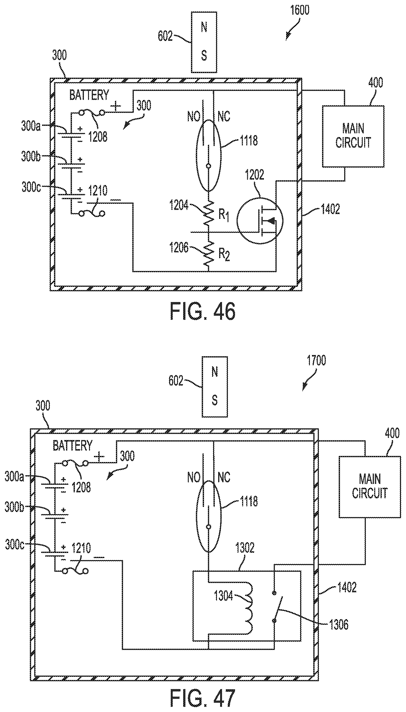
D00032

D00033

D00034

D00035

D00036

D00037

D00038
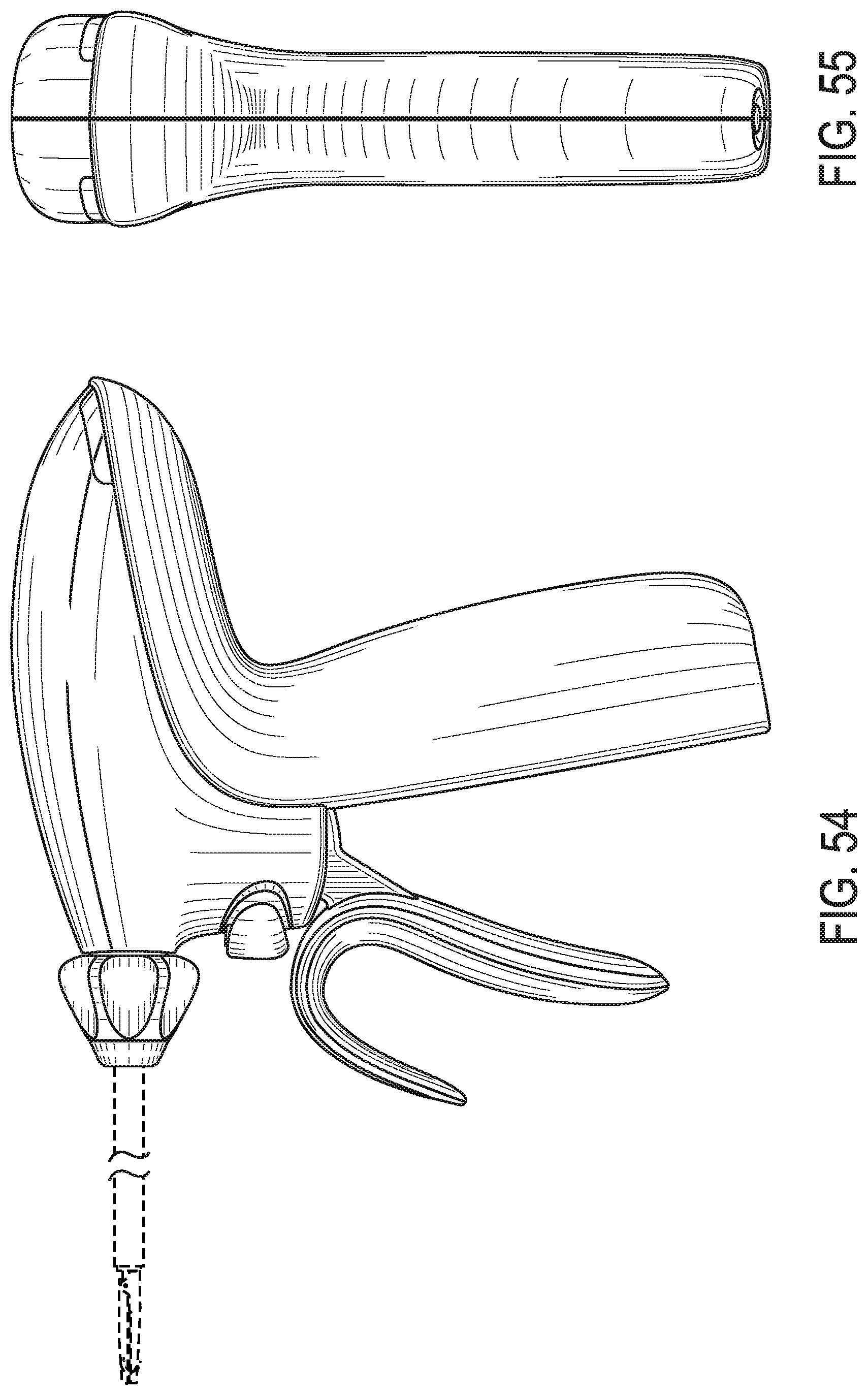
D00039

XML
uspto.report is an independent third-party trademark research tool that is not affiliated, endorsed, or sponsored by the United States Patent and Trademark Office (USPTO) or any other governmental organization. The information provided by uspto.report is based on publicly available data at the time of writing and is intended for informational purposes only.
While we strive to provide accurate and up-to-date information, we do not guarantee the accuracy, completeness, reliability, or suitability of the information displayed on this site. The use of this site is at your own risk. Any reliance you place on such information is therefore strictly at your own risk.
All official trademark data, including owner information, should be verified by visiting the official USPTO website at www.uspto.gov. This site is not intended to replace professional legal advice and should not be used as a substitute for consulting with a legal professional who is knowledgeable about trademark law.