Electrical connector with grounding member
Bence , et al. A
U.S. patent number 10,756,455 [Application Number 14/166,653] was granted by the patent office on 2020-08-25 for electrical connector with grounding member. This patent grant is currently assigned to Corning Optical Communications RF LLC. The grantee listed for this patent is Corning Optical Communications RF LLC. Invention is credited to Bruce D. Bence, Donald A. Burris, Lee Yung Chuan, Brian L. Kisling, John A. Kooiman, William B. Lutz, William F. McDade, Thomas D. Miller.

| United States Patent | 10,756,455 |
| Bence , et al. | August 25, 2020 |
Electrical connector with grounding member
Abstract
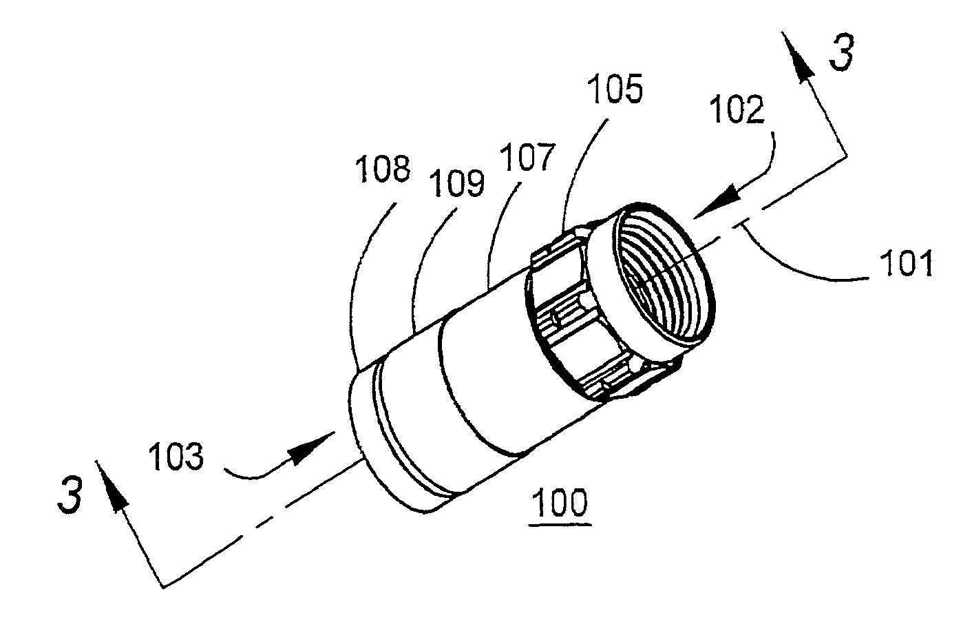
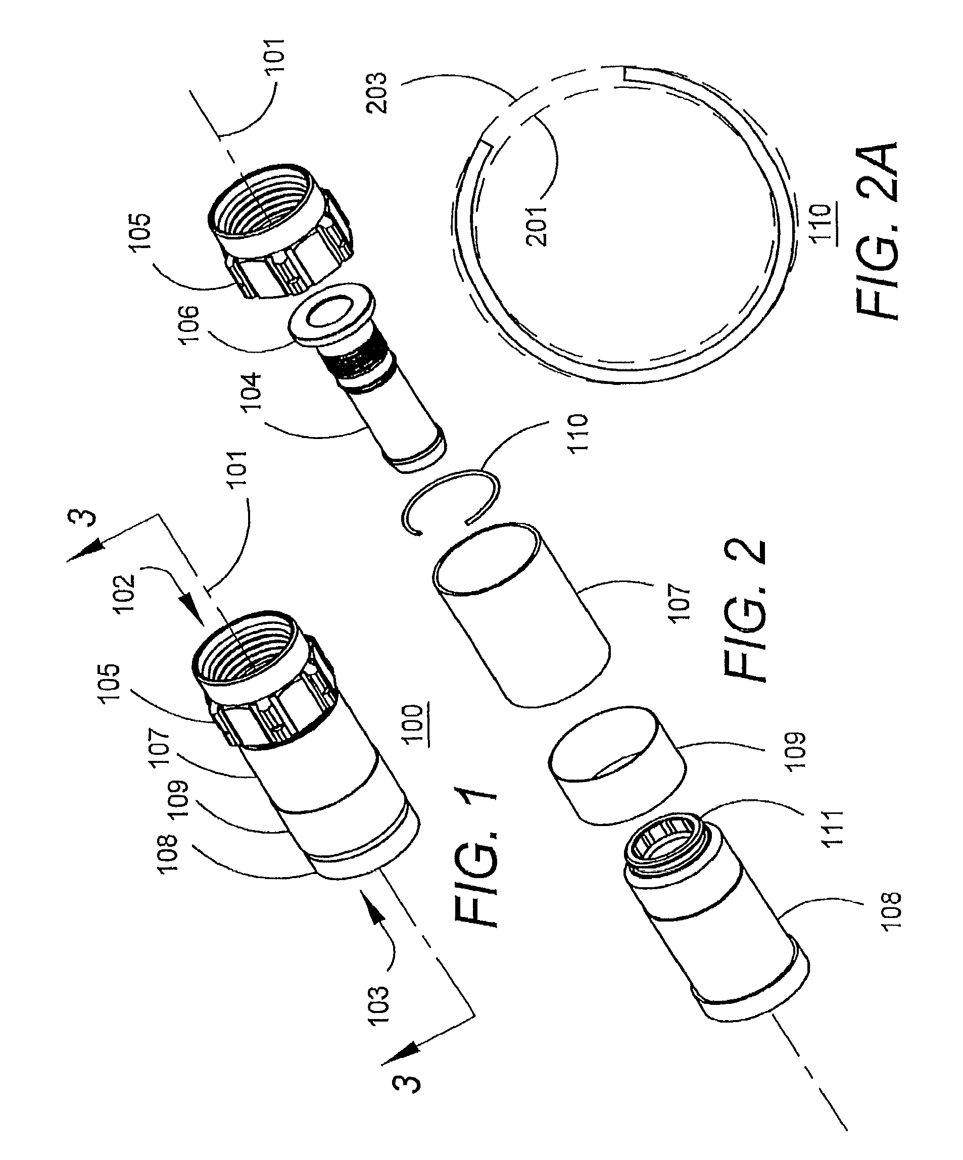
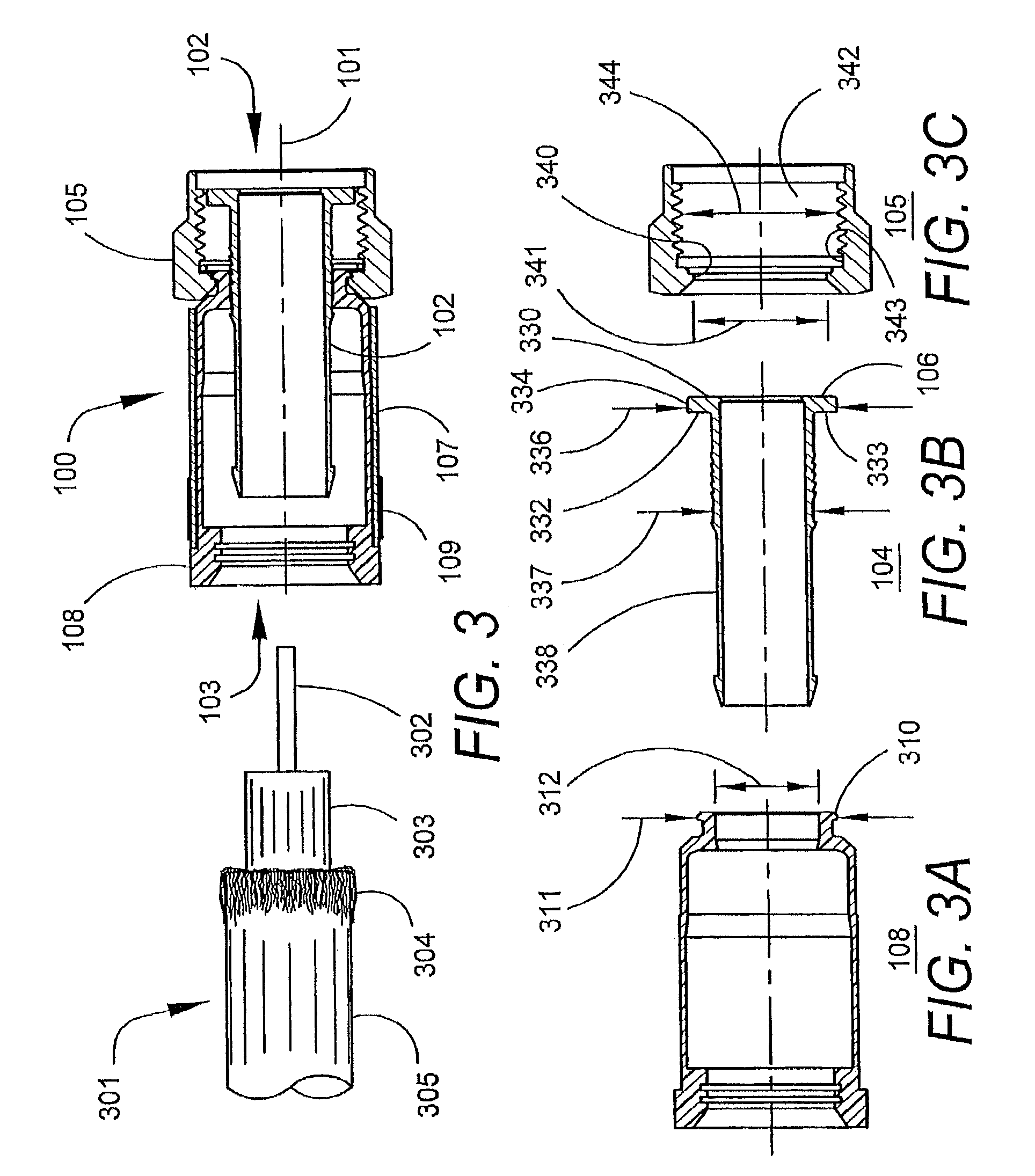
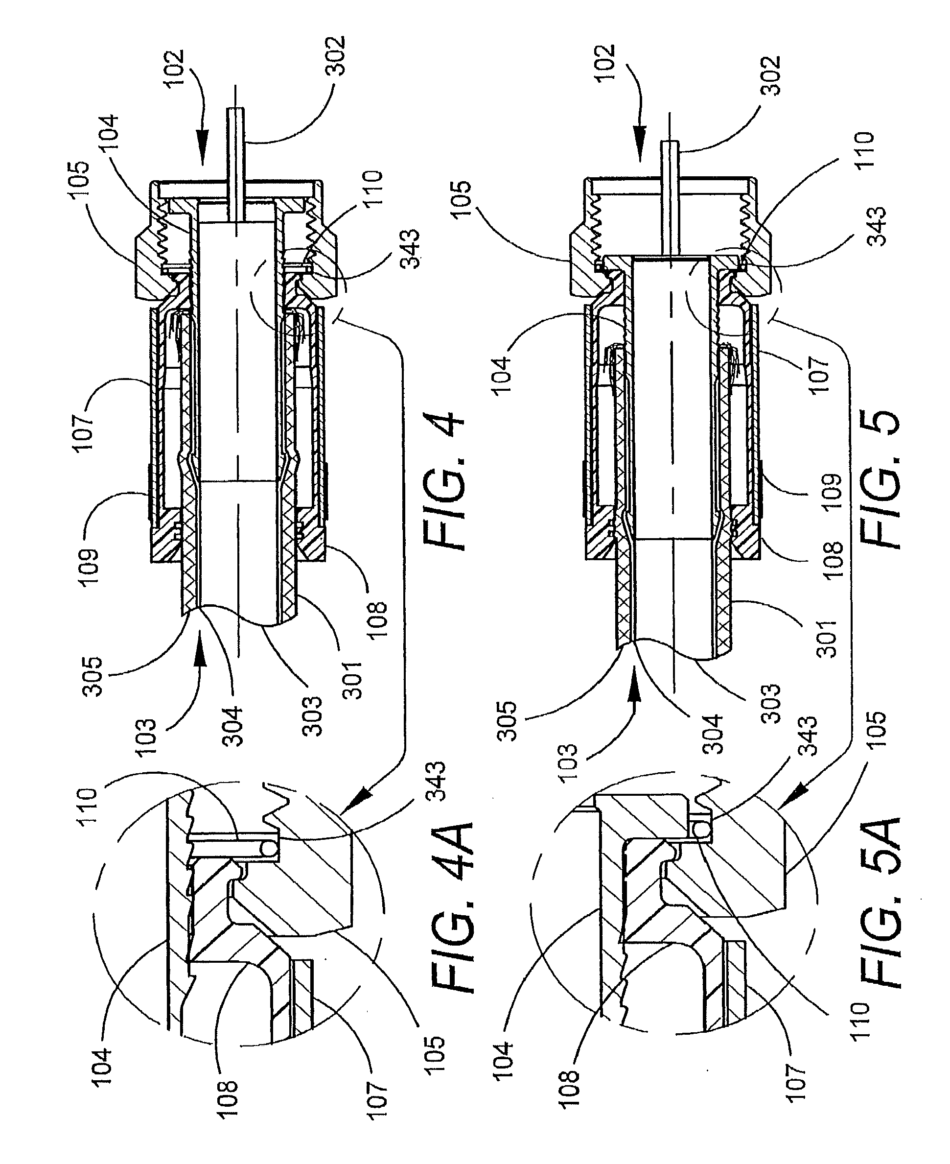
A coaxial cable connector for coupling a coaxial cable to an equipment port, the coaxial cable including a center conductor surrounded by a dielectric material, the dielectric material being surrounded by an outer conductor, the coaxial cable connector including: a post including a first end adapted to be inserted into a prepared end of the coaxial cable between the dielectric material and the outer conductor, wherein the post includes a second end including an enlarged shoulder, wherein the enlarged shoulder has a radial face that faces away from the first end of the post, wherein the radial face is substantially flat; a body member adjacent to the post; a coupler including an internally-threaded region for engaging the equipment port; and a grounding member contacting the post and the coupler, wherein the grounding member provides an electrically-conductive grounding path through the post and the coupler while allowing the coupler to rotate, wherein the grounding member includes at least one resilient portion.
| Inventors: | Bence; Bruce D. (Glendale, AZ), Burris; Donald A. (Peoria, AZ), Kisling; Brian L. (Phoenix, AZ), Kooiman; John A. (Peoria, AZ), Lutz; William B. (Glendale, AZ), McDade; William F. (Glendale, AZ), Miller; Thomas D. (Peoria, AZ), Chuan; Lee Yung (Sanchong, TW) | ||||||||||
|---|---|---|---|---|---|---|---|---|---|---|---|
| Applicant: |
|
||||||||||
| Assignee: | Corning Optical Communications RF
LLC (Glendale, AZ) |
||||||||||
| Family ID: | 36168366 | ||||||||||
| Appl. No.: | 14/166,653 | ||||||||||
| Filed: | January 28, 2014 |
Prior Publication Data
| Document Identifier | Publication Date | |
|---|---|---|
| US 20140148051 A1 | May 29, 2014 | |
Related U.S. Patent Documents
| Application Number | Filing Date | Patent Number | Issue Date | ||
|---|---|---|---|---|---|
| 13438532 | Apr 3, 2012 | 8690603 | |||
| 13117843 | May 27, 2011 | 8172612 | |||
| 12332925 | Dec 11, 2008 | 7955126 | |||
| 11541903 | Oct 2, 2006 | 7479035 | |||
| 11043844 | Jan 25, 2005 | 7114990 | |||
| Current U.S. Class: | 1/1 |
| Current CPC Class: | H01R 24/44 (20130101); H01R 9/05 (20130101); H01R 43/20 (20130101); H01R 13/5216 (20130101); H01R 2103/00 (20130101); H01R 13/5202 (20130101) |
| Current International Class: | H01R 9/05 (20060101); H01R 24/44 (20110101); H01R 43/20 (20060101); H01R 13/52 (20060101) |
| Field of Search: | ;439/583,584,320,322,314 |
References Cited [Referenced By]
U.S. Patent Documents
| 331169 | November 1885 | Thomas |
| 346958 | August 1886 | Stone |
| 459951 | September 1891 | Warner |
| 589216 | August 1897 | McKee |
| 1371742 | March 1921 | Dringman |
| 1488175 | March 1924 | Strandell |
| 1667485 | April 1928 | MacDonald |
| 1766869 | June 1930 | Austin |
| 1801999 | April 1931 | Bowman |
| 1885761 | November 1932 | Peirce, Jr. |
| 1959302 | May 1934 | Paige |
| 2013526 | September 1935 | Schmitt |
| 2059920 | November 1936 | Weatherhead, Jr. |
| 2102495 | December 1937 | England |
| 2258528 | October 1941 | Wurzburger |
| 2258737 | October 1941 | Browne |
| 2325549 | July 1943 | Ryzowitz |
| 2480963 | September 1949 | Quinn |
| 2544654 | March 1951 | Brown |
| 2549647 | April 1951 | Turenne |
| 2694187 | November 1954 | Nash |
| 2705652 | April 1955 | Kaiser |
| 2743505 | May 1956 | Hill |
| 2754487 | July 1956 | Carr et al. |
| 2755331 | July 1956 | Melcher |
| 2757351 | July 1956 | Klostermann |
| 2762025 | September 1956 | Melcher |
| 2785384 | March 1957 | Wickesser |
| 2805399 | September 1957 | Leeper |
| 2816949 | December 1957 | Curtiss |
| 2870420 | January 1959 | Malek |
| 2878039 | March 1959 | Hoegee et al. |
| 2881406 | April 1959 | Arson |
| 2963536 | December 1960 | Kokalas |
| 3001169 | September 1961 | Blonder |
| 3015794 | January 1962 | Kishbaugh |
| 3051925 | August 1962 | Felts |
| 3091748 | May 1963 | Takes et al. |
| 3094364 | June 1963 | Lingg |
| 3103548 | September 1963 | Concelman |
| 3106548 | October 1963 | Lavalou |
| 3140106 | July 1964 | Thomas et al. |
| 3161451 | December 1964 | Neidecker |
| 3184706 | May 1965 | Atkins |
| 3193309 | July 1965 | Morris |
| 3194292 | July 1965 | Borowsky |
| 3196382 | July 1965 | Morello, Jr. |
| 3206540 | September 1965 | Cohen |
| 3245027 | April 1966 | Ziegler, Jr. |
| 3275913 | September 1966 | Blanchard et al. |
| 3278890 | October 1966 | Cooney |
| 3281756 | October 1966 | O'Keefe et al. |
| 3281757 | October 1966 | Bonhomme |
| 3290069 | December 1966 | Davis |
| 3292136 | December 1966 | Somerset |
| 3320575 | May 1967 | Brown et al. |
| 3321732 | May 1967 | Forney, Jr. |
| 3336563 | August 1967 | Hyslop |
| 3348186 | October 1967 | Rosen |
| 3350667 | October 1967 | Shreve |
| 3350677 | October 1967 | Daum |
| 3355698 | November 1967 | Keller |
| 3372364 | March 1968 | O'Keefe et al. |
| 3373243 | March 1968 | Janowiak et al. |
| 3390374 | June 1968 | Forney, Jr. |
| 3406373 | October 1968 | Forney, Jr. |
| 3430184 | February 1969 | Acord |
| 3448430 | June 1969 | Kelly |
| 3453376 | July 1969 | Ziegler, Jr. et al. |
| 3465281 | September 1969 | Florer |
| 3475545 | October 1969 | Stark et al. |
| 3494400 | February 1970 | McCoy et al. |
| 3498647 | March 1970 | Schroder |
| 3499671 | March 1970 | Osborne |
| 3501737 | March 1970 | Harris et al. |
| 3517373 | June 1970 | Jamon |
| 3526871 | September 1970 | Hobart |
| 3533051 | October 1970 | Ziegler, Jr. |
| 3537065 | October 1970 | Winston |
| 3544705 | December 1970 | Winston |
| 3551882 | December 1970 | O'Keefe |
| 3564487 | February 1971 | Upstone et al. |
| 3587033 | June 1971 | Brorein et al. |
| 3596933 | August 1971 | Luckenbill |
| 3601776 | August 1971 | Curl |
| 3603912 | September 1971 | Kelly |
| 3614711 | October 1971 | Anderson et al. |
| 3622952 | November 1971 | Hilbert |
| 3629792 | December 1971 | Dorrell |
| 3633150 | January 1972 | Schwartz |
| 3646502 | February 1972 | Hutter et al. |
| 3663926 | May 1972 | Brandt |
| 3665371 | May 1972 | Cripps |
| 3668612 | June 1972 | Nepovim |
| 3669472 | June 1972 | Nadsady |
| 3671922 | June 1972 | Zerlin et al. |
| 3671926 | June 1972 | Nepovim |
| 3678444 | July 1972 | Stevens et al. |
| 3678445 | July 1972 | Brancaloene |
| 3680034 | July 1972 | Chow et al. |
| 3681739 | August 1972 | Kornick |
| 3683320 | August 1972 | Woods et al. |
| 3686623 | August 1972 | Nijman |
| 3694792 | September 1972 | Wallo |
| 3694793 | September 1972 | Concelman |
| 3697930 | October 1972 | Shirey |
| 3706958 | December 1972 | Blanchenot |
| 3708186 | January 1973 | Takagi et al. |
| 3710005 | January 1973 | French |
| 3739076 | June 1973 | Schwartz |
| 3744007 | July 1973 | Horak |
| 3744011 | July 1973 | Blanchenot |
| 3761870 | September 1973 | Drezin et al. |
| 3778535 | December 1973 | Forney, Jr. |
| 3781762 | December 1973 | Quackenbush |
| 3781898 | December 1973 | Holloway |
| 3783178 | January 1974 | Philibert et al. |
| 3787796 | January 1974 | Barr |
| 3793610 | February 1974 | Brishka |
| 3798589 | March 1974 | Deardurff |
| 3808580 | April 1974 | Johnson |
| 3810076 | May 1974 | Hutter |
| 3824026 | July 1974 | Gaskins |
| 3835443 | September 1974 | Arnold et al. |
| 3836700 | September 1974 | Niemeyer |
| 3845453 | October 1974 | Hemmer |
| 3846738 | November 1974 | Nepovim |
| 3847463 | November 1974 | Hayward et al. |
| 3854003 | December 1974 | Duret |
| 3854789 | December 1974 | Kaplan |
| 3858156 | December 1974 | Zarro |
| 3879102 | April 1975 | Horak |
| 3886301 | May 1975 | Cronin et al. |
| 3907335 | September 1975 | Burge et al. |
| 3907399 | September 1975 | Spinner |
| 3910673 | October 1975 | Stokes |
| 3915539 | October 1975 | Collins |
| 3936132 | February 1976 | Hutter |
| 3937547 | February 1976 | Lee-Kemp |
| 3953097 | April 1976 | Graham |
| 3960428 | June 1976 | Naus et al. |
| 3963320 | June 1976 | Spinner |
| 3963321 | June 1976 | Burger et al. |
| 3970355 | July 1976 | Pitschi |
| 3972013 | July 1976 | Shapiro |
| 3976352 | August 1976 | Spinner |
| 3980805 | September 1976 | Lipari |
| 3985418 | October 1976 | Spinner |
| 3986736 | October 1976 | Takagi et al. |
| 4012105 | March 1977 | Biddle |
| 4017139 | April 1977 | Nelson |
| 4022966 | May 1977 | Gajajiva |
| 4030742 | June 1977 | Eidelberg et al. |
| 4030798 | June 1977 | Paoli |
| 4032177 | June 1977 | Anderson |
| 4045706 | August 1977 | Daffner et al. |
| 4046451 | September 1977 | Juds et al. |
| 4053200 | October 1977 | Pugner |
| 4056043 | November 1977 | Sriramamurty et al. |
| 4059330 | November 1977 | Shirey |
| 4079343 | March 1978 | Nijman |
| 4082404 | April 1978 | Flatt |
| 4090028 | May 1978 | Vontobel |
| 4093335 | June 1978 | Schwartz et al. |
| 4100943 | July 1978 | Terada et al. |
| 4106839 | August 1978 | Cooper |
| 4109126 | August 1978 | Halbeck |
| 4118097 | October 1978 | Budnick |
| 4125308 | November 1978 | Schilling |
| 4126372 | November 1978 | Hashimoto et al. |
| 4131332 | December 1978 | Hogendobler et al. |
| 4136897 | January 1979 | Haluch |
| 4150250 | April 1979 | Lundeberg |
| 4153320 | May 1979 | Townshend |
| 4156554 | May 1979 | Aujla |
| 4165911 | August 1979 | Laudig |
| 4168921 | September 1979 | Blanchard |
| 4173385 | November 1979 | Fenn et al. |
| 4174875 | November 1979 | Wilson et al. |
| 4187481 | February 1980 | Bourtos |
| 4193655 | March 1980 | Herrmann, Jr. |
| 4194338 | March 1980 | Trafton |
| 4197628 | April 1980 | Conti et al. |
| 4206963 | June 1980 | English et al. |
| 4212487 | July 1980 | Jones et al. |
| 4225162 | September 1980 | Dola |
| 4227765 | October 1980 | Neumann et al. |
| 4229714 | October 1980 | Yu |
| 4239318 | December 1980 | Schwartz |
| 4250348 | February 1981 | Kitagawa |
| 4260212 | April 1981 | Ritchie |
| 4273405 | June 1981 | Law |
| 4280749 | July 1981 | Hemmer |
| 4285564 | August 1981 | Spinner |
| 4290663 | September 1981 | Fowler et al. |
| 4296986 | October 1981 | Herrmann, Jr. |
| 4307926 | December 1981 | Smith |
| 4309050 | January 1982 | Legris |
| 4310211 | January 1982 | Bunnell et al. |
| 4322121 | March 1982 | Riches et al. |
| 4326768 | April 1982 | Punako |
| 4326769 | April 1982 | Dorsey et al. |
| 4334730 | June 1982 | Colwell et al. |
| 4339166 | July 1982 | Dayton |
| 4345375 | August 1982 | Hayward |
| 4346958 | August 1982 | Blanchard |
| 4354721 | October 1982 | Luzzi |
| 4358174 | November 1982 | Dreyer |
| 4373767 | February 1983 | Cairns |
| 4389081 | June 1983 | Gallusser et al. |
| 4400050 | August 1983 | Hayward |
| 4407529 | October 1983 | Holman |
| 4408821 | October 1983 | Forney, Jr. |
| 4408822 | October 1983 | Nikitas |
| 4412717 | November 1983 | Monroe |
| 4421377 | December 1983 | Spinner |
| 4426127 | January 1984 | Kubota |
| 4428639 | January 1984 | Hillis |
| 4444453 | April 1984 | Kirby et al. |
| 4447107 | May 1984 | Major et al. |
| 4452503 | June 1984 | Forney, Jr. |
| 4456323 | June 1984 | Pitcher et al. |
| 4459881 | July 1984 | Hughes, Jr. |
| 4462653 | July 1984 | Flederbach et al. |
| 4464000 | August 1984 | Werth et al. |
| 4464001 | August 1984 | Collins |
| 4469386 | September 1984 | Ackerman |
| 4470657 | September 1984 | Deacon |
| 4477132 | October 1984 | Moser et al. |
| 4484792 | November 1984 | Tengler et al. |
| 4484796 | November 1984 | Sato et al. |
| 4490576 | December 1984 | Bolante et al. |
| 4491685 | January 1985 | Drew et al. |
| 4506943 | March 1985 | Drogo |
| 4515427 | May 1985 | Smit |
| 4525017 | June 1985 | Schildkraut |
| 4531790 | July 1985 | Selvin |
| 4531805 | July 1985 | Werth |
| 4533191 | August 1985 | Blackwood |
| 4540231 | September 1985 | Forney, Jr. |
| RE31995 | October 1985 | Ball |
| 4545633 | October 1985 | McGeary |
| 4545637 | October 1985 | Bosshard et al. |
| 4553877 | November 1985 | Edvardsen |
| 4575274 | March 1986 | Hayward |
| 4580862 | April 1986 | Johnson |
| 4580865 | April 1986 | Fryberger |
| 4583811 | April 1986 | McMills |
| 4585289 | April 1986 | Bocher |
| 4588246 | May 1986 | Schildkraut et al. |
| 4593964 | June 1986 | Forney, Jr. et al. |
| 4596434 | June 1986 | Saba et al. |
| 4596435 | June 1986 | Bickford |
| 4597621 | July 1986 | Burns |
| 4598959 | July 1986 | Selvin |
| 4598961 | July 1986 | Cohen |
| 4600263 | July 1986 | DeChamp et al. |
| 4613199 | September 1986 | McGeary |
| 4614390 | September 1986 | Baker |
| 4616900 | October 1986 | Cairns |
| 4623205 | November 1986 | Barron |
| 4632487 | December 1986 | Wargula |
| 4634213 | January 1987 | Larsson et al. |
| 4640572 | February 1987 | Conlon |
| 4645281 | February 1987 | Burger |
| 4647135 | March 1987 | Reinhardt |
| 4650228 | March 1987 | McMills et al. |
| 4655159 | April 1987 | McMills |
| 4655534 | April 1987 | Stursa |
| 4660921 | April 1987 | Hauver |
| 4666190 | May 1987 | Yamabe et al. |
| 4666231 | May 1987 | Sheesley et al. |
| 4668043 | May 1987 | Saba et al. |
| 4670574 | June 1987 | Malcolm |
| 4673236 | June 1987 | Musolff et al. |
| 4674809 | June 1987 | Hollyday et al. |
| 4674818 | June 1987 | McMills et al. |
| 4676577 | June 1987 | Szegda |
| 4682832 | July 1987 | Punako et al. |
| 4684201 | August 1987 | Hutter |
| 4688876 | August 1987 | Morelli |
| 4688878 | August 1987 | Cohen et al. |
| 4690482 | September 1987 | Chamberland et al. |
| 4691976 | September 1987 | Cowen |
| 4703987 | November 1987 | Gullusser et al. |
| 4703988 | November 1987 | Raux et al. |
| 4713021 | December 1987 | Kobler |
| 4717355 | January 1988 | Mattis |
| 4720155 | January 1988 | Schildkraut et al. |
| 4728301 | March 1988 | Hemmer et al. |
| 4734050 | March 1988 | Negre et al. |
| 4734666 | March 1988 | Ohya et al. |
| 4737123 | April 1988 | Paler et al. |
| 4738009 | April 1988 | Down et al. |
| 4738628 | April 1988 | Rees |
| 4739009 | April 1988 | Down et al. |
| 4739126 | April 1988 | Gutter et al. |
| 4746305 | May 1988 | Nomura |
| 4747656 | May 1988 | Miyahara et al. |
| 4747786 | May 1988 | Hayashi et al. |
| 4749821 | June 1988 | Linton et al. |
| 4755152 | July 1988 | Elliot et al. |
| 4757297 | July 1988 | Frawley |
| 4759729 | July 1988 | Kemppainen et al. |
| 4761146 | August 1988 | Sohoel |
| 4772222 | September 1988 | Laudig et al. |
| 4789355 | December 1988 | Lee |
| 4789759 | December 1988 | Jones |
| 4795360 | January 1989 | Newman et al. |
| 4797120 | January 1989 | Ulery |
| 4806116 | February 1989 | Ackerman |
| 4807891 | February 1989 | Neher |
| 4808128 | February 1989 | Werth |
| 4810017 | March 1989 | Knak et al. |
| 4813886 | March 1989 | Roos et al. |
| 4820185 | April 1989 | Moulin |
| 4834675 | May 1989 | Samchisen |
| 4834676 | May 1989 | Tackett |
| 4835342 | May 1989 | Guginsky |
| 4836580 | June 1989 | Farrell |
| 4836801 | June 1989 | Ramirez |
| 4838813 | June 1989 | Pauza et al. |
| 4846731 | July 1989 | Alwine |
| 4854893 | August 1989 | Morris |
| 4857014 | August 1989 | Alf et al. |
| 4867489 | September 1989 | Patel |
| 4867706 | September 1989 | Tang |
| 4869679 | September 1989 | Szegda |
| 4874331 | October 1989 | Iverson |
| 4881912 | November 1989 | Thommen et al. |
| 4892275 | January 1990 | Szegda |
| 4902246 | February 1990 | Samchisen |
| 4906207 | March 1990 | Banning et al. |
| 4915651 | April 1990 | Bout |
| 4921447 | May 1990 | Capp et al. |
| 4923412 | May 1990 | Morris |
| 4925403 | May 1990 | Zorzy |
| 4927385 | May 1990 | Cheng |
| 4929188 | May 1990 | Lionetto et al. |
| 4934960 | June 1990 | Capp et al. |
| 4938718 | July 1990 | Guendel |
| 4941846 | July 1990 | Guimond et al. |
| 4952174 | August 1990 | Sucht et al. |
| 4957456 | September 1990 | Olson et al. |
| 4963105 | October 1990 | Lewis et al. |
| 4964805 | October 1990 | Gabany |
| 4964812 | October 1990 | Siemon et al. |
| 4973265 | November 1990 | Heeren |
| 4976632 | December 1990 | Riches |
| 4979911 | December 1990 | Spencer |
| 4990104 | February 1991 | Schieferly |
| 4990105 | February 1991 | Karlovich |
| 4990106 | February 1991 | Szegda |
| 4992061 | February 1991 | Brush, Jr. et al. |
| 5002503 | March 1991 | Campbell et al. |
| 5007861 | April 1991 | Stirling |
| 5011422 | April 1991 | Yeh |
| 5011432 | April 1991 | Sucht et al. |
| 5018822 | May 1991 | Freismuth et al. |
| 5021010 | June 1991 | Wright |
| 5024606 | June 1991 | Ming-Hwa |
| 5030126 | July 1991 | Hanlon |
| 5037328 | August 1991 | Karlovich |
| 5046964 | September 1991 | Welsh et al. |
| 5052947 | October 1991 | Brodie et al. |
| 5055060 | October 1991 | Down et al. |
| 5059139 | October 1991 | Spinner |
| 5059747 | October 1991 | Bawa |
| 5062804 | November 1991 | Jamet et al. |
| 5066248 | November 1991 | Gaver, Jr. et al. |
| 5067912 | November 1991 | Bickford et al. |
| 5073129 | December 1991 | Szegda |
| 5074809 | December 1991 | Rousseau et al. |
| 5080600 | January 1992 | Baker et al. |
| 5083943 | January 1992 | Tarrant |
| 5088937 | February 1992 | Gabany |
| 5120260 | June 1992 | Jackson |
| 5127853 | July 1992 | McMills et al. |
| 5131862 | July 1992 | Gershfeld |
| 5137470 | August 1992 | Doles |
| 5137471 | August 1992 | Verespej |
| 5139440 | August 1992 | Volk et al. |
| 5141448 | August 1992 | Mattingly et al. |
| 5141451 | August 1992 | Down |
| 5149274 | September 1992 | Gallusser et al. |
| 5150924 | September 1992 | Yokomatsu et al. |
| 5154636 | October 1992 | Vaccaro et al. |
| 5161993 | November 1992 | Leibfried, Jr. |
| 5166477 | November 1992 | Perin, Jr. et al. |
| 5167545 | December 1992 | O'Brien et al. |
| 5169323 | December 1992 | Kawai et al. |
| 5176530 | January 1993 | Reylek |
| 5176533 | January 1993 | Sakurai et al. |
| 5181161 | January 1993 | Hirose et al. |
| 5183417 | February 1993 | Bools |
| 5185655 | February 1993 | Glenday, et al. |
| 5186501 | February 1993 | Mano |
| 5186655 | February 1993 | Glenday et al. |
| 5195904 | March 1993 | Cyvoct |
| 5195905 | March 1993 | Pesci |
| 5195906 | March 1993 | Szegda |
| 5205547 | April 1993 | Mattingly |
| 5205761 | April 1993 | Nilsson |
| D335487 | May 1993 | Volk et al. |
| 5207602 | May 1993 | McMills et al. |
| 5215477 | June 1993 | Weber et al. |
| 5217391 | June 1993 | Fisher, Jr. |
| 5217392 | June 1993 | Hosler, Sr. |
| 5217393 | June 1993 | Del Negro et al. |
| 5221216 | June 1993 | Gabany et al. |
| 5227587 | July 1993 | Paterek |
| 5247424 | September 1993 | Harris et al. |
| 5269701 | December 1993 | Leibfried, Jr. |
| 5281762 | January 1994 | Long et al. |
| 5283853 | February 1994 | Szegda |
| 5284449 | February 1994 | Vaccaro |
| 5294864 | March 1994 | Do |
| 5295864 | March 1994 | Birch et al. |
| 5316348 | May 1994 | Franklin |
| 5316494 | May 1994 | Flanagan et al. |
| 5318459 | June 1994 | Sheilds |
| 5321205 | June 1994 | Bawa et al. |
| 5334032 | August 1994 | Myers et al. |
| 5334051 | August 1994 | Devine et al. |
| 5338225 | August 1994 | Jacobsen et al. |
| 5342218 | August 1994 | McMills et al. |
| 5352134 | October 1994 | Jacobsen et al. |
| 5354217 | October 1994 | Gabel et al. |
| 5362250 | November 1994 | McMills et al. |
| 5362251 | November 1994 | Bielak |
| 5366260 | November 1994 | Wartluft |
| 5371819 | December 1994 | Szegda |
| 5371821 | December 1994 | Szegda |
| 5371827 | December 1994 | Szegda |
| 5380211 | January 1995 | Kawagauchi et al. |
| 5389005 | February 1995 | Kodama |
| 5393244 | February 1995 | Szegda |
| 5397252 | March 1995 | Wang |
| 5413504 | May 1995 | Kloecker et al. |
| 5431583 | July 1995 | Szegda |
| 5435745 | July 1995 | Booth |
| 5435751 | July 1995 | Papenheim et al. |
| 5435760 | July 1995 | Miklos |
| 5439386 | August 1995 | Ellis et al. |
| 5444810 | August 1995 | Szegda |
| 5455548 | October 1995 | Grandchamp et al. |
| 5456611 | October 1995 | Henry et al. |
| 5456614 | October 1995 | Szegda |
| 5466173 | November 1995 | Down |
| 5470257 | November 1995 | Szegda |
| 5474478 | December 1995 | Ballog |
| 5475921 | December 1995 | Johnston |
| 5488268 | January 1996 | Bauer et al. |
| 5490033 | February 1996 | Cronin |
| 5490801 | February 1996 | Fisher, Jr. et al. |
| 5494454 | February 1996 | Johnsen |
| 5499934 | March 1996 | Jacobsen et al. |
| 5501616 | March 1996 | Holliday |
| 5511305 | April 1996 | Garner |
| 5516303 | May 1996 | Yohn et al. |
| 5525076 | June 1996 | Down |
| 5542861 | August 1996 | Anhalt et al. |
| 5548088 | August 1996 | Gray et al. |
| 5550521 | August 1996 | Bernaud et al. |
| 5564938 | October 1996 | Shenkal et al. |
| 5571028 | November 1996 | Szegda |
| 5586910 | December 1996 | Del Negro et al. |
| 5595499 | January 1997 | Zander et al. |
| 5598132 | January 1997 | Stabile |
| 5607320 | March 1997 | Wright |
| 5607325 | March 1997 | Toma |
| 5609501 | March 1997 | McMills et al. |
| 5620339 | April 1997 | Gray et al. |
| 5632637 | May 1997 | Diener |
| 5632651 | May 1997 | Szegda |
| 5644104 | July 1997 | Porter et al. |
| 5649723 | July 1997 | Larsson |
| 5651698 | July 1997 | Locati et al. |
| 5651699 | July 1997 | Holliday |
| 5653605 | August 1997 | Woehl et al. |
| 5667405 | September 1997 | Holliday |
| 5681172 | October 1997 | Moldenhauer |
| 5683263 | November 1997 | Hsu |
| 5702263 | December 1997 | Baumann et al. |
| 5722856 | March 1998 | Fuchs et al. |
| 5735704 | April 1998 | Anthony |
| 5743131 | April 1998 | Holliday et al. |
| 5746617 | May 1998 | Porter, Jr. et al. |
| 5746619 | May 1998 | Harting et al. |
| 5759618 | June 1998 | Taylor |
| 5769652 | June 1998 | Wider |
| 5769662 | June 1998 | Stabile et al. |
| 5774344 | June 1998 | Casebolt |
| 5775927 | July 1998 | Wider |
| 5788289 | August 1998 | Cronley |
| 5791698 | August 1998 | Wartluft et al. |
| 5797633 | August 1998 | Katzer et al. |
| 5817978 | October 1998 | Hermant et al. |
| 5863220 | January 1999 | Holliday |
| 5874603 | February 1999 | Arkles |
| 5877452 | March 1999 | McConnell |
| 5879191 | March 1999 | Burris |
| 5882226 | March 1999 | Bell et al. |
| 5890924 | April 1999 | Endo |
| 5897795 | April 1999 | Lu et al. |
| 5906511 | May 1999 | Bozzer et al. |
| 5917153 | June 1999 | Geroldinger |
| 5921793 | July 1999 | Phillips |
| 5938465 | August 1999 | Fox, Sr. |
| 5944548 | August 1999 | Saito |
| 5951327 | September 1999 | Marik |
| 5954708 | September 1999 | Lopez et al. |
| 5957716 | September 1999 | Buckley et al. |
| 5967852 | October 1999 | Follingstad et al. |
| 5975479 | November 1999 | Suter |
| 5975591 | November 1999 | Guest |
| 5975949 | November 1999 | Holliday et al. |
| 5975951 | November 1999 | Burris et al. |
| 5977841 | November 1999 | Lee et al. |
| 5997350 | December 1999 | Burris et al. |
| 6010349 | January 2000 | Porter, Jr. |
| 6019635 | February 2000 | Nelson |
| 6022237 | February 2000 | Esh |
| 6032358 | March 2000 | Wild |
| 6036540 | March 2000 | Beloritsky |
| 6042422 | March 2000 | Youtsey |
| 6048229 | April 2000 | Lazaro, Jr. |
| 6053743 | April 2000 | Mitchell et al. |
| 6053769 | April 2000 | Kubota et al. |
| 6053777 | April 2000 | Boyle |
| 6062607 | May 2000 | Barthlomew |
| 6080015 | June 2000 | Andreescu |
| 6083030 | July 2000 | Wright |
| 6083053 | July 2000 | Anderson, Jr. et al. |
| 6089903 | July 2000 | Stafford Gray et al. |
| 6089912 | July 2000 | Tallis et al. |
| 6089913 | July 2000 | Holliday |
| 6093043 | July 2000 | Gray et al. |
| 6095828 | August 2000 | Burland |
| 6095841 | August 2000 | Felps |
| 6123550 | September 2000 | Burkert et al. |
| 6123567 | September 2000 | McCarthy |
| 6126487 | October 2000 | Rosenberger et al. |
| 6132234 | October 2000 | Waidner et al. |
| 6142812 | November 2000 | Hwang |
| 6146197 | November 2000 | Holliday et al. |
| 6152752 | November 2000 | Fukuda |
| 6152753 | November 2000 | Johnson et al. |
| 6153830 | November 2000 | Montena |
| 6162995 | December 2000 | Bachle et al. |
| 6164977 | December 2000 | Lester |
| 6174206 | January 2001 | Yentile et al. |
| 6183298 | February 2001 | Henningsen |
| 6199913 | March 2001 | Wang |
| 6199920 | March 2001 | Neustadtl |
| 6210216 | April 2001 | Tso-Chin et al. |
| 6210219 | April 2001 | Zhu et al. |
| 6210222 | April 2001 | Langham et al. |
| 6217383 | April 2001 | Holland et al. |
| 6238240 | May 2001 | Yu |
| 6239359 | May 2001 | Lilienthal, II et al. |
| 6241553 | June 2001 | Hsia |
| 6250942 | June 2001 | Lemke et al. |
| 6250974 | June 2001 | Kerek |
| 6257923 | July 2001 | Stone et al. |
| 6261126 | July 2001 | Stirling |
| 6267612 | July 2001 | Areykiewicz et al. |
| 6271464 | August 2001 | Cunningham |
| 6331123 | December 2001 | Rodrigues |
| 6332815 | December 2001 | Bruce |
| 6352448 | March 2002 | Holliday et al. |
| 6358077 | March 2002 | Young |
| 6361348 | March 2002 | Hall et al. |
| 6361364 | March 2002 | Holland et al. |
| 6375509 | April 2002 | Mountford |
| 6379183 | April 2002 | Ayres et al. |
| 6394840 | May 2002 | Gassauer et al. |
| 6396367 | May 2002 | Rosenberger |
| D458904 | June 2002 | Montena |
| 6398571 | June 2002 | Nishide et al. |
| 6406330 | June 2002 | Bruce |
| 6409534 | June 2002 | Weisz-Margulescu |
| D460739 | July 2002 | Fox |
| D460740 | July 2002 | Montena |
| D460946 | July 2002 | Montena |
| D460947 | July 2002 | Montena |
| D460948 | July 2002 | Montena |
| 6422884 | July 2002 | Babasick et al. |
| 6422900 | July 2002 | Hogan |
| 6425782 | July 2002 | Holland |
| D461166 | August 2002 | Montena |
| D461167 | August 2002 | Montena |
| D461778 | August 2002 | Fox |
| D462058 | August 2002 | Montena |
| D462060 | August 2002 | Fox |
| 6439899 | August 2002 | Muzslay et al. |
| D462327 | September 2002 | Montena |
| 6443763 | September 2002 | Richet |
| 6450829 | September 2002 | Weisz-Margulescu |
| 6454463 | September 2002 | Halbach |
| 6464526 | October 2002 | Seufert et al. |
| 6464527 | October 2002 | Volpe et al. |
| 6467816 | October 2002 | Huang |
| 6468100 | October 2002 | Meyer et al. |
| 6491546 | December 2002 | Perry |
| D468696 | January 2003 | Montena |
| 6506083 | January 2003 | Bickford et al. |
| 6510610 | January 2003 | Losinger |
| 6520800 | February 2003 | Michelbach et al. |
| 6530807 | March 2003 | Rodrigues et al. |
| 6540531 | April 2003 | Syed et al. |
| 6558194 | May 2003 | Montena |
| 6572419 | June 2003 | Feye-Homann |
| 6576833 | June 2003 | Covaro et al. |
| 6619876 | September 2003 | Vaitkus et al. |
| 6634906 | October 2003 | Yeh |
| 6637101 | October 2003 | Hathaway et al. |
| 6645011 | November 2003 | Schneider et al. |
| 6663397 | December 2003 | Lin et al. |
| 6676446 | January 2004 | Montena |
| 6683253 | January 2004 | Lee |
| 6683773 | January 2004 | Montena |
| 6692285 | February 2004 | Islam |
| 6692286 | February 2004 | De Cet |
| 6695636 | February 2004 | Hall et al. |
| 6705875 | March 2004 | Berghorn et al. |
| 6705884 | March 2004 | McCarthy |
| 6709280 | March 2004 | Gretz |
| 6709289 | March 2004 | Huber et al. |
| 6712631 | March 2004 | Youtsey |
| 6716041 | April 2004 | Ferderer et al. |
| 6716062 | April 2004 | Palinkas et al. |
| 6733336 | May 2004 | Montena et al. |
| 6733337 | May 2004 | Kodaira |
| 6743040 | June 2004 | Nakamura |
| 6749454 | June 2004 | Schmidt et al. |
| 6751081 | June 2004 | Kooiman |
| 6752633 | June 2004 | Aizawa et al. |
| 6761571 | July 2004 | Hida |
| 6767248 | July 2004 | Hung |
| 6769926 | August 2004 | Montena |
| 6780029 | August 2004 | Gretz |
| 6780042 | August 2004 | Badescu et al. |
| 6780052 | August 2004 | Montena et al. |
| 6780068 | August 2004 | Bartholoma et al. |
| 6783394 | August 2004 | Holliday |
| 6786767 | September 2004 | Fuks et al. |
| 6790081 | September 2004 | Burris et al. |
| 6793528 | September 2004 | Lin et al. |
| 6796847 | September 2004 | AbuGhezaleh |
| 6802738 | October 2004 | Henningsen |
| 6805581 | October 2004 | Chen |
| 6805583 | October 2004 | Holliday et al. |
| 6805584 | October 2004 | Chen |
| 6808415 | October 2004 | Montena |
| 6817272 | November 2004 | Holland |
| 6817896 | November 2004 | Derenthal |
| 6817897 | November 2004 | Chee |
| 6827608 | December 2004 | Hall et al. |
| 6830479 | December 2004 | Holliday |
| 6848115 | January 2005 | Sugiura et al. |
| 6848939 | February 2005 | Stirling |
| 6848940 | February 2005 | Montena |
| 6848941 | February 2005 | Wlos et al. |
| 6884113 | April 2005 | Montena |
| 6884115 | April 2005 | Malloy |
| 6887102 | May 2005 | Burris et al. |
| 6916200 | July 2005 | Burris et al. |
| 6929265 | August 2005 | Holland et al. |
| 6929508 | August 2005 | Holland |
| 6935866 | August 2005 | Kerekes et al. |
| 6939169 | September 2005 | Islam et al. |
| 6942516 | September 2005 | Shimoyama et al. |
| 6942520 | September 2005 | Barlian et al. |
| 6945805 | September 2005 | Bollinger |
| 6948976 | September 2005 | Goodwin et al. |
| 6953371 | October 2005 | Baker et al. |
| 6955563 | October 2005 | Croan |
| D511497 | November 2005 | Murphy et al. |
| D512024 | November 2005 | Murphy et al. |
| D512689 | December 2005 | Murphy et al. |
| 6971912 | December 2005 | Montena et al. |
| 7008263 | March 2006 | Holland |
| 7018216 | March 2006 | Clark et al. |
| 7018235 | March 2006 | Burris et al. |
| 7029326 | April 2006 | Montena |
| D521454 | May 2006 | Murphy et al. |
| 7063565 | June 2006 | Ward |
| 7070447 | July 2006 | Montena |
| 7077697 | July 2006 | Kooiman |
| 7077699 | July 2006 | Islam et al. |
| 7086897 | August 2006 | Montena |
| 7090525 | August 2006 | Morana |
| 7094114 | August 2006 | Kurimoto |
| 7097499 | August 2006 | Purdy |
| 7102868 | September 2006 | Montena |
| 7108547 | September 2006 | Kisling et al. |
| 7108548 | September 2006 | Burris et al. |
| 7112078 | September 2006 | Czikora |
| 7112093 | September 2006 | Holland |
| 7114990 | October 2006 | Bence et al. |
| 7117990 | October 2006 | Sarif |
| 7118285 | October 2006 | Fenwick et al. |
| 7118382 | October 2006 | Kerekes et al. |
| 7118416 | October 2006 | Montena et al. |
| 7125283 | October 2006 | Lin |
| 7128603 | October 2006 | Burris et al. |
| 7128604 | October 2006 | Hall |
| 7131867 | November 2006 | Foster et al. |
| 7131868 | November 2006 | Montena |
| 7140645 | November 2006 | Cronley |
| 7144271 | December 2006 | Burris et al. |
| 7144272 | December 2006 | Burris et al. |
| 7147509 | December 2006 | Burris et al. |
| 7153159 | December 2006 | Burris et al. |
| 7156696 | January 2007 | Montena |
| 7161785 | January 2007 | Chawgo |
| 7165974 | January 2007 | Kooiman |
| 7173121 | February 2007 | Fang |
| 7179121 | February 2007 | Burris et al. |
| 7179122 | February 2007 | Holliday |
| 7182639 | February 2007 | Burris |
| 7183639 | February 2007 | Mihara et al. |
| 7189097 | March 2007 | Benham |
| 7189114 | March 2007 | Burris et al. |
| 7192308 | March 2007 | Rodrigues et al. |
| 7229303 | June 2007 | Vermoesen et al. |
| 7238047 | July 2007 | Saetele et al. |
| 7252536 | August 2007 | Lazaro, Jr. et al. |
| 7252546 | August 2007 | Holland |
| 7255598 | August 2007 | Montena et al. |
| 7261594 | August 2007 | Kodama et al. |
| 7264502 | September 2007 | Holland |
| 7278882 | October 2007 | Li |
| 7288002 | October 2007 | Rodrigues et al. |
| 7291033 | November 2007 | Hu |
| 7297023 | November 2007 | Chawgo |
| 7299550 | November 2007 | Montena |
| 7303435 | December 2007 | Burris et al. |
| 7311555 | December 2007 | Burris et al. |
| 7318609 | January 2008 | Naito et al. |
| 7322846 | January 2008 | Camelio |
| 7322851 | January 2008 | Brookmire |
| 7329139 | February 2008 | Benham |
| 7331820 | February 2008 | Burris et al. |
| 7335058 | February 2008 | Burris et al. |
| 7347129 | March 2008 | Youtsey |
| 7347726 | March 2008 | Wlos |
| 7347727 | March 2008 | Wlos et al. |
| 7347729 | March 2008 | Thomas et al. |
| 7351088 | April 2008 | Qu |
| 7357641 | April 2008 | Kerekes et al. |
| 7364462 | April 2008 | Holland |
| 7371112 | May 2008 | Burris et al. |
| 7371113 | May 2008 | Burris et al. |
| 7375533 | May 2008 | Gale |
| 7387524 | June 2008 | Cheng |
| 7393245 | July 2008 | Palinkas et al. |
| 7396249 | July 2008 | Kauffman |
| 7404737 | July 2008 | Youtsey |
| 7410389 | August 2008 | Holliday |
| 7416415 | August 2008 | Hart et al. |
| 7438327 | October 2008 | Auray et al. |
| 7452239 | November 2008 | Montena |
| 7455550 | November 2008 | Sykes |
| 7458850 | December 2008 | Burris et al. |
| 7458851 | December 2008 | Montena |
| 7462068 | December 2008 | Amidon |
| 7467980 | December 2008 | Chiu |
| 7476127 | January 2009 | Wei |
| 7478475 | January 2009 | Hall |
| 7479033 | January 2009 | Sykes et al. |
| 7479035 | January 2009 | Bence et al. |
| 7484988 | February 2009 | Ma et al. |
| 7484997 | February 2009 | Hofling |
| 7488210 | February 2009 | Burris et al. |
| 7494355 | February 2009 | Hughes et al. |
| 7497729 | March 2009 | Wei |
| 7500868 | March 2009 | Holland et al. |
| 7500873 | March 2009 | Hart |
| 7507116 | March 2009 | Laerke et al. |
| 7507117 | March 2009 | Amidon |
| 7513788 | April 2009 | Camelio |
| 7537482 | May 2009 | Burris et al. |
| 7540759 | June 2009 | Liu et al. |
| 7544094 | June 2009 | Paglia et al. |
| 7563133 | July 2009 | Stein |
| 7566236 | July 2009 | Malloy et al. |
| 7568945 | August 2009 | Chee et al. |
| 7578693 | August 2009 | Yoshida et al. |
| 7588454 | September 2009 | Nakata et al. |
| 7607942 | October 2009 | Van Swearingen |
| 7625227 | December 2009 | Henderson et al. |
| 7632143 | December 2009 | Islam |
| 7635283 | December 2009 | Islam |
| 7648383 | January 2010 | Burris et al. |
| 7651376 | January 2010 | Schreier |
| 7674132 | March 2010 | Chen |
| 7682177 | March 2010 | Berthet |
| 7694420 | April 2010 | Ehret et al. |
| 7714229 | May 2010 | Burris et al. |
| 7726996 | June 2010 | Burris et al. |
| 7727011 | June 2010 | Montena et al. |
| 7749021 | July 2010 | Brodeur |
| 7753705 | July 2010 | Montena |
| 7753710 | July 2010 | George |
| 7753727 | July 2010 | Islam et al. |
| 7758356 | July 2010 | Burris et al. |
| 7758370 | July 2010 | Flaherty |
| 7794275 | September 2010 | Rodrigues |
| 7806714 | October 2010 | Williams et al. |
| 7806725 | October 2010 | Chen |
| 7811133 | October 2010 | Gray |
| 7814654 | October 2010 | Pichler |
| D626920 | November 2010 | Purdy et al. |
| 7824216 | November 2010 | Purdy |
| 7828594 | November 2010 | Burris et al. |
| 7828595 | November 2010 | Mathews |
| 7830154 | November 2010 | Gale |
| 7833053 | November 2010 | Mathews |
| 7845976 | December 2010 | Mathews |
| 7845978 | December 2010 | Chen |
| 7845980 | December 2010 | Amidon |
| 7850472 | December 2010 | Friedrich et al. |
| 7850487 | December 2010 | Wei |
| 7857661 | December 2010 | Islam |
| 7874870 | January 2011 | Chen |
| 7887354 | February 2011 | Holliday |
| 7892004 | February 2011 | Hertzler et al. |
| 7892005 | February 2011 | Haube |
| 7892024 | February 2011 | Chen |
| 7914326 | March 2011 | Sutter |
| 7918687 | April 2011 | Paynter et al. |
| 7927135 | April 2011 | Wlos |
| 7934955 | May 2011 | Hsia |
| 7938662 | May 2011 | Burris et al. |
| 7942695 | May 2011 | Lu |
| 7950958 | May 2011 | Mathews |
| 7950961 | May 2011 | Chabalowski et al. |
| 7955126 | June 2011 | Bence et al. |
| 7972158 | July 2011 | Wild et al. |
| 7972176 | July 2011 | Burris et al. |
| 7982005 | July 2011 | Ames et al. |
| 8011955 | September 2011 | Lu |
| 8025518 | September 2011 | Burris et al. |
| 8029315 | October 2011 | Purdy et al. |
| 8029316 | October 2011 | Snyder et al. |
| 8037599 | October 2011 | Pichler |
| 8047872 | November 2011 | Burris et al. |
| 8062044 | November 2011 | Montena et al. |
| 8062063 | November 2011 | Malloy et al. |
| 8070504 | December 2011 | Amidon et al. |
| 8075337 | December 2011 | Malloy et al. |
| 8075338 | December 2011 | Montena |
| 8079860 | December 2011 | Zraik |
| 8087954 | January 2012 | Fuchs |
| 8113875 | February 2012 | Malloy et al. |
| 8113879 | February 2012 | Zraik |
| 8157587 | April 2012 | Paynter et al. |
| 8157588 | April 2012 | Rodrigues et al. |
| 8167635 | May 2012 | Mathews |
| 8167636 | May 2012 | Montena |
| 8172612 | May 2012 | Bence et al. |
| 8177572 | May 2012 | Feye-Hohmann |
| 8192237 | June 2012 | Purdy et al. |
| 8206172 | June 2012 | Katagiri et al. |
| D662893 | July 2012 | Haberek et al. |
| 8231412 | July 2012 | Paglia et al. |
| 8262408 | September 2012 | Kelly |
| 8272893 | September 2012 | Burris et al. |
| 8287310 | October 2012 | Burris et al. |
| 8287320 | October 2012 | Purdy et al. |
| 8313345 | November 2012 | Purdy |
| 8313353 | November 2012 | Purdy et al. |
| 8317539 | November 2012 | Stein |
| 8319136 | November 2012 | Byron et al. |
| 8323053 | December 2012 | Montena |
| 8323058 | December 2012 | Flaherty et al. |
| 8323060 | December 2012 | Purdy et al. |
| 8337229 | December 2012 | Montena |
| 8366481 | February 2013 | Ehret et al. |
| 8366482 | February 2013 | Burris et al. |
| 8376769 | February 2013 | Holland et al. |
| D678844 | March 2013 | Haberek |
| 8398421 | March 2013 | Haberek et al. |
| 8430688 | April 2013 | Montena et al. |
| 8449326 | May 2013 | Holland et al. |
| 8465322 | June 2013 | Purdy |
| 8469739 | June 2013 | Rodrigues et al. |
| 8469740 | June 2013 | Ehret et al. |
| D686164 | July 2013 | Haberek et al. |
| D686576 | July 2013 | Haberek et al. |
| 8475205 | July 2013 | Ehret et al. |
| 8480430 | July 2013 | Ehret et al. |
| 8480431 | July 2013 | Ehret et al. |
| 8485845 | July 2013 | Ehret et al. |
| 8506325 | August 2013 | Malloy et al. |
| 8517763 | August 2013 | Burris et al. |
| 8517764 | August 2013 | Wei et al. |
| 8529279 | September 2013 | Montena |
| 8550835 | October 2013 | Montena |
| 8568163 | October 2013 | Burris et al. |
| 8568165 | October 2013 | Wei et al. |
| 8591244 | November 2013 | Thomas et al. |
| 8597050 | December 2013 | Flaherty et al. |
| 8622776 | January 2014 | Morikawa |
| 8636529 | January 2014 | Stein |
| 8636541 | January 2014 | Chastain et al. |
| 8647136 | February 2014 | Purdy et al. |
| 7114990 | April 2014 | Bence et al. |
| 8690603 | April 2014 | Bence et al. |
| 8721365 | May 2014 | Holland |
| 8727800 | May 2014 | Holland et al. |
| 8777658 | July 2014 | Holland et al. |
| 8777661 | July 2014 | Holland et al. |
| 8172612 | September 2014 | Bence et al. |
| 8858251 | October 2014 | Montena |
| 8888526 | November 2014 | Burris |
| 8920192 | December 2014 | Montena |
| 6558194 | January 2015 | Montena |
| 6848940 | January 2015 | Montena |
| 9017101 | April 2015 | Ehret et al. |
| 9048599 | June 2015 | Burris |
| 9153911 | October 2015 | Burris et al. |
| 9166348 | October 2015 | Burris et al. |
| 9172154 | October 2015 | Burris |
| 9172157 | October 2015 | Burris |
| 2001/0034143 | October 2001 | Annequin |
| 2001/0046802 | November 2001 | Perry et al. |
| 2001/0051448 | December 2001 | Gonzalez |
| 2002/0013088 | January 2002 | Rodrigues et al. |
| 2002/0019161 | February 2002 | Finke et al. |
| 2002/0038720 | April 2002 | Kai et al. |
| 2002/0146935 | October 2002 | Wong |
| 2003/0110977 | June 2003 | Batlaw |
| 2003/0119358 | June 2003 | Henningsen |
| 2003/0139081 | July 2003 | Hall et al. |
| 2003/0194890 | October 2003 | Ferderer et al. |
| 2003/0214370 | November 2003 | Allison et al. |
| 2003/0224657 | December 2003 | Malloy |
| 2004/0031144 | February 2004 | Holland |
| 2004/0077215 | April 2004 | Palinkas et al. |
| 2004/0102089 | May 2004 | Chee |
| 2004/0137778 | July 2004 | Mattheeuws et al. |
| 2004/0157499 | August 2004 | Nania et al. |
| 2004/0194585 | October 2004 | Clark |
| 2004/0209516 | October 2004 | Burris |
| 2004/0219833 | November 2004 | Burris et al. |
| 2004/0229504 | November 2004 | Liu |
| 2005/0042919 | February 2005 | Montena |
| 2005/0079762 | April 2005 | Hsia |
| 2005/0159045 | July 2005 | Huang |
| 2005/0170692 | August 2005 | Montena |
| 2005/0181652 | August 2005 | Montena et al. |
| 2005/0181668 | August 2005 | Montena et al. |
| 2005/0208827 | September 2005 | Burris et al. |
| 2005/0219833 | October 2005 | Wu et al. |
| 2005/0233636 | October 2005 | Rodrigues et al. |
| 2006/0014425 | January 2006 | Montena |
| 2006/0099853 | May 2006 | Sattele et al. |
| 2006/0110977 | May 2006 | Matthews |
| 2006/0113107 | June 2006 | Williams |
| 2006/0154519 | July 2006 | Montena |
| 2006/0166552 | July 2006 | Bence et al. |
| 2006/0178046 | August 2006 | Tusini |
| 2006/0194465 | August 2006 | Czikora |
| 2006/0199040 | September 2006 | Yamada |
| 2006/0223355 | October 2006 | Hirschmann |
| 2006/0246774 | November 2006 | Buck |
| 2006/0258209 | November 2006 | Hall |
| 2006/0276079 | December 2006 | Chen |
| 2007/0004276 | January 2007 | Stein |
| 2007/0026734 | February 2007 | Bence et al. |
| 2007/0049113 | March 2007 | Rodrigues et al. |
| 2007/0054535 | March 2007 | Hall et al. |
| 2007/0059968 | March 2007 | Ohtaka et al. |
| 2007/0082533 | April 2007 | Currier et al. |
| 2007/0087613 | April 2007 | Schumacher et al. |
| 2007/0123101 | May 2007 | Palinkas |
| 2007/0155232 | July 2007 | Burris et al. |
| 2007/0173100 | July 2007 | Benham |
| 2007/0175027 | August 2007 | Khemakhem et al. |
| 2007/0232117 | October 2007 | Singer |
| 2007/0243759 | October 2007 | Rodrigues et al. |
| 2007/0243762 | October 2007 | Burke et al. |
| 2007/0287328 | December 2007 | Hart et al. |
| 2008/0032556 | February 2008 | Schreier |
| 2008/0102696 | May 2008 | Montena |
| 2008/0171466 | July 2008 | Buck et al. |
| 2008/0200066 | August 2008 | Hofling |
| 2008/0200068 | August 2008 | Aguirre |
| 2008/0214040 | September 2008 | Holterhoff et al. |
| 2008/0289470 | November 2008 | Aston |
| 2008/0310026 | December 2008 | Nakayama |
| 2009/0029590 | January 2009 | Sykes et al. |
| 2009/0098770 | April 2009 | Bence et al. |
| 2009/0104801 | April 2009 | Silva |
| 2009/0163075 | June 2009 | Blew et al. |
| 2009/0186505 | July 2009 | Mathews |
| 2009/0264003 | October 2009 | Hertzler et al. |
| 2009/0305560 | December 2009 | Chen |
| 2010/0007441 | January 2010 | Yagisawa et al. |
| 2010/0022125 | January 2010 | Burris et al. |
| 2010/0028563 | February 2010 | Ota |
| 2010/0055978 | March 2010 | Montena |
| 2010/0080563 | April 2010 | DiFonzo et al. |
| 2010/0081321 | April 2010 | Malloy et al. |
| 2010/0081322 | April 2010 | Malloy et al. |
| 2010/0087071 | April 2010 | DiFonzo et al. |
| 2010/0105246 | April 2010 | Burris et al. |
| 2010/0124839 | May 2010 | Montena |
| 2010/0130060 | May 2010 | Islam |
| 2010/0178799 | July 2010 | Lee |
| 2010/0216339 | August 2010 | Burris et al. |
| 2010/0233901 | September 2010 | Wild et al. |
| 2010/0233902 | September 2010 | Youtsey |
| 2010/0233903 | September 2010 | Islam |
| 2010/0255719 | October 2010 | Purdy |
| 2010/0255721 | October 2010 | Purdy et al. |
| 2010/0279548 | November 2010 | Montena et al. |
| 2010/0297871 | November 2010 | Haube |
| 2010/0297875 | November 2010 | Purdy et al. |
| 2010/0304579 | December 2010 | Kisling |
| 2010/0323541 | December 2010 | Amidon et al. |
| 2011/0021072 | January 2011 | Purdy |
| 2011/0021075 | January 2011 | Orner et al. |
| 2011/0027039 | February 2011 | Blair |
| 2011/0039448 | February 2011 | Stein |
| 2011/0053413 | March 2011 | Mathews |
| 2011/0074388 | March 2011 | Bowman |
| 2011/0080158 | April 2011 | Lawrence et al. |
| 2011/0111623 | May 2011 | Burris et al. |
| 2011/0111626 | May 2011 | Paglia et al. |
| 2011/0117774 | May 2011 | Malloy et al. |
| 2011/0143567 | June 2011 | Purdy et al. |
| 2011/0151714 | June 2011 | Flaherty et al. |
| 2011/0230089 | September 2011 | Amidon et al. |
| 2011/0230091 | September 2011 | Krenceski et al. |
| 2011/0237123 | September 2011 | Burris et al. |
| 2011/0237124 | September 2011 | Flaherty et al. |
| 2011/0250789 | October 2011 | Burris et al. |
| 2011/0318958 | December 2011 | Burris et al. |
| 2012/0021642 | January 2012 | Zraik |
| 2012/0040537 | February 2012 | Burris |
| 2012/0045933 | February 2012 | Youtsey |
| 2012/0064768 | March 2012 | Islam et al. |
| 2012/0094530 | April 2012 | Montena |
| 2012/0100751 | April 2012 | Montena |
| 2012/0108098 | May 2012 | Burris et al. |
| 2012/0122329 | May 2012 | Montena |
| 2012/0129387 | May 2012 | Holland et al. |
| 2012/0171894 | July 2012 | Malloy et al. |
| 2012/0178289 | July 2012 | Holliday |
| 2012/0202378 | August 2012 | Krenceski et al. |
| 2012/0222302 | September 2012 | Purdy et al. |
| 2012/0225581 | September 2012 | Amidon et al. |
| 2012/0315788 | December 2012 | Montena |
| 2013/0065433 | March 2013 | Burris |
| 2013/0072057 | March 2013 | Burris |
| 2013/0178096 | July 2013 | Matzen |
| 2013/0273761 | October 2013 | Ehret et al. |
| 2014/0106612 | April 2014 | Burris |
| 2014/0106613 | April 2014 | Burris |
| 2014/0120766 | May 2014 | Meister et al. |
| 2014/0137393 | May 2014 | Chastain et al. |
| 2014/0148044 | May 2014 | Balcer et al. |
| 2014/0148051 | May 2014 | Bence et al. |
| 2014/0154907 | June 2014 | Ehret et al. |
| 2014/0298650 | October 2014 | Chastain et al. |
| 2014/0322968 | October 2014 | Burris |
| 2014/0342605 | November 2014 | Burris et al. |
| 2015/0118901 | April 2015 | Burris |
| 2015/0295331 | October 2015 | Burris |
| 2096710 | Nov 1994 | CA | |||
| 201149936 | Nov 2008 | CN | |||
| 201149937 | Nov 2008 | CN | |||
| 201178228 | Jan 2009 | CN | |||
| 201904508 | Jul 2011 | CN | |||
| 47931 | Oct 1888 | DE | |||
| 102289 | Jul 1897 | DE | |||
| 1117687 | Nov 1961 | DE | |||
| 1191880 | Apr 1965 | DE | |||
| 1515398 | Apr 1970 | DE | |||
| 2225764 | Dec 1972 | DE | |||
| 2221936 | Nov 1973 | DE | |||
| 2261973 | Jun 1974 | DE | |||
| 3117320 | Apr 1982 | DE | |||
| 3211008 | Oct 1983 | DE | |||
| 3211008 | Oct 1983 | DE | |||
| 9001608.4 | Apr 1990 | DE | |||
| 4439852 | May 1996 | DE | |||
| 19749130 | Aug 1999 | DE | |||
| 19957518 | Sep 2001 | DE | |||
| 10346914 | May 2004 | DE | |||
| 115179 | Aug 1984 | EP | |||
| 116157 | Aug 1984 | EP | |||
| 167738 | Jan 1986 | EP | |||
| 72104 | Feb 1986 | EP | |||
| 223464 | May 1987 | EP | |||
| 265276 | Apr 1988 | EP | |||
| 350835 | Jan 1990 | EP | |||
| 428424 | May 1991 | EP | |||
| 867978 | Sep 1998 | EP | |||
| 1069654 | Sep 1998 | EP | |||
| 1094565 | Apr 2001 | EP | |||
| 1115179 | Jul 2001 | EP | |||
| 1191268 | Mar 2002 | EP | |||
| 1455420 | Sep 2004 | EP | |||
| 1501159 | Jan 2005 | EP | |||
| 1548898 | Jun 2005 | EP | |||
| 1603200 | Dec 2005 | EP | |||
| 1701410 | Sep 2006 | EP | |||
| 2051340 | Apr 2009 | EP | |||
| 2204331 | May 1974 | FR | |||
| 2232846 | Jan 1975 | FR | |||
| 2234680 | Jan 1975 | FR | |||
| 2312918 | Dec 1976 | FR | |||
| 2462798 | Feb 1981 | FR | |||
| 2494508 | May 1982 | FR | |||
| 589697 | Jun 1947 | GB | |||
| 1087228 | Oct 1967 | GB | |||
| 1270846 | Apr 1972 | GB | |||
| 1332888 | Oct 1973 | GB | |||
| 1332888 | Oct 1973 | GB | |||
| 1401373 | Jul 1975 | GB | |||
| 1421215 | Jan 1976 | GB | |||
| 2019665 | Oct 1979 | GB | |||
| 2079549 | Jan 1982 | GB | |||
| 2252677 | Aug 1992 | GB | |||
| 2264201 | Aug 1993 | GB | |||
| 2331634 | May 1999 | GB | |||
| 2448595 | Oct 2008 | GB | |||
| 2450248 | Dec 2008 | GB | |||
| 2477479 | Aug 2011 | GB | |||
| 3280369 | Dec 1991 | JP | |||
| 200215823 | Jan 2002 | JP | |||
| 4129978 | Aug 2008 | JP | |||
| 2009277571 | Nov 2009 | JP | |||
| 4391268 | Dec 2009 | JP | |||
| 4503793 | Jul 2010 | JP | |||
| 100622526 | Sep 2006 | KR | |||
| 427044 | Mar 2001 | TW | |||
| 87/00351 | Jan 1987 | WO | |||
| 8700351 | Jan 1987 | WO | |||
| 00/05785 | Feb 2000 | WO | |||
| 0186756 | Nov 2001 | WO | |||
| 02069457 | Sep 2002 | WO | |||
| 2004013883 | Feb 2004 | WO | |||
| 2004098795 | Nov 2004 | WO | |||
| 2006081141 | Aug 2006 | WO | |||
| 2007062845 | Jun 2007 | WO | |||
| 2009066705 | May 2009 | WO | |||
| 2010135181 | Nov 2010 | WO | |||
| 2011057033 | May 2011 | WO | |||
| 2011128665 | Oct 2011 | WO | |||
| 2011128666 | Oct 2011 | WO | |||
| 2012162431 | Nov 2012 | WO | |||
| 2013126629 | Aug 2013 | WO | |||
Other References
|
Office Action dated Dec. 31, 2014 pertaining to U.S. Appl. No. 13/605,498. cited by applicant . Office Action dated Dec. 16, 2014 pertaining to U.S. Appl. No. 13/653,095. cited by applicant . Office Action dated Dec. 19, 2014 pertaining to U.S. Appl. No. 13/652,969. cited by applicant . Office Action dated Dec. 29, 2014 pertaining to U.S. Appl. No. 13/833,793. cited by applicant . Notice of Allowance (Mail Date Mar. 20, 2012) for U.S. Appl. No. 13/117,843, filed May 27, 2011. cited by applicant . Notice of Allowance dated Feb. 2, 2015 pertaining to U.S. Appl. No. 13/795,737. cited by applicant . Office Action dated Feb. 25, 2015 pertaining to U.S. Appl. No. 13/605,481. cited by applicant . Office Action dated Feb. 18, 2015 pertaining to U.S. Appl. No. 13/827,522. cited by applicant . Office Action dated Mar. 19, 2015 pertaining to U.S. Appl. No. 13/795,780. cited by applicant . Office Action dated Jun. 24, 2015 pertaining to U.S. Appl. No. 13/652,969. cited by applicant . Patent Cooperation Treaty, International Preliminary Report on Patentability for PCT/US2013/064512, mail date Apr. 30, 2015, 9 pages. cited by applicant . Patent Cooperation Treaty, International Preliminary Report on Patentability for PCT/US2013/064515, mail date Apr. 30, 2015, 8 pages. cited by applicant . Corning Gilbert 2004 OEM Coaxial Products Catalog, Quick Disconnects, 2 pages. cited by applicant . Digicon AVL Connector. ARRIS Group Inc. [online] 3 pages. Retrieved from the Internet: <URL: http://www.arrisi.com/special/digiconAVL.asp. cited by applicant . US Office Action, U.S. Appl. No. 10/997,218; Jul. 31, 2006, pp. 1-10. cited by applicant . Society of Cable Telecommunications Engineers, Engineering Committee, Interface Practices Subcommittee; American National Standard; ANSI/SCTE Jan. 2006; Specification for "F" Port, Female, Outdoor. Published Jan. 2006. 9 pages. cited by applicant . The American Society of Mechanical Engineers; "Lock Washers (Inch Series), An American National Standard"; ASME 818.21.1-1999 (Revision of ASME B18.21.1-1994); Reaffirmed 2005. Published Feb. 11, 2000. 28 pages. cited by applicant . U.S. Reexamination Control No. 90/012,300 filed Jun. 29, 2012, regarding U.S. Pat. No. 8,172,612 filed May 27, 2011 (Bence et al.). cited by applicant . U.S. Reexamination Control No. 90/012,749 filed Dec. 21, 2012, regarding U.S. Pat. No. 7,114,990, filed Jan. 25, 2005 (Bence et al.). cited by applicant . U.S. Reexamination Control No. 90/012,835 filed Apr. 11, 2013, regarding U.S. Pat. No. 8,172,612 filed May 27, 2011 (Bence et al.). cited by applicant . Notice of Allowance (Mail Date Mar. 20, 2012) for U.S. Appl. No. 13/117,843. cited by applicant . Search Report dated Jun. 6, 2014 pertaining to International application No. PCT/US2014/023374. cited by applicant . Search Report dated Apr. 9, 2014 pertaining to International application No. PCT/US2014/015934. cited by applicant . Society of Cable Telecommunications Engineers, Engineering Committee, Interface Practices Subcommittee; American National Standard; ANSI/SCTE Feb. 2006; "Specification for "F" Port, Female, Indoor". Published Feb. 2006. 9 pages. cited by applicant . PPC, "Next Generation Compression Connectors," pp. 1-6, Retrieved from http://www.tessco.com/yts/partnearnanufacturer list/vendors/ppc/pdf/ppc digital spread.pdf. cited by applicant . Patent Cooperation Treaty, International Search Report for PCT/US2013/070497, Feb. 11, 2014, 3 pgs. cited by applicant . Patent Cooperation Treaty, International Search Report for PCT/US2013/064515, 10 pgs. cited by applicant . Patent Cooperation Treaty, International Search Report for PCT/US2013/064512, Jan. 21, 2014, 11 pgs. cited by applicant . Huber+Suhner AG, RF Connector Guide: Understanding connector technology, 2007, Retrieved from http://www.ie.itcr.ac.cr/marin/lic/e14515/HUBER+SUENER_RF_Connector_Guide- .pdf. cited by applicant . Slade, Paul G,. Electrical Contacts: Principles and Applications, 1999, Retrieved from http://books.google.com/books (table of contents only). cited by applicant . U.S. Reexamination Control No. 95/002,400 filed Sep. 15, 2012, regarding U.S. Pat. No. 8,192,237 filed Feb. 23, 2011 (Purdy et al.). cited by applicant . U.S. Reexamination Control No. 90/013,068 filed Nov. 27, 2013, regarding U.S. Pat. No. 6,558,194 filed Jul. 21, 2000 (Montena). cited by applicant . U.S. Reexamination Control No. 90/013,069 filed Nov. 27, 2013, regarding U.S. Pat. No. 6,848,940 filed Jan. 21, 2003 (Montena). cited by applicant . U.S. Inter Partes Review Case No. 2013-00346 filed Jun. 10, 2013, regarding U.S. Pat. No. 8,287,320 filed Dec. 8, 2009, claims 1-8, 10-16, 18-31 (Purdy et al.). cited by applicant . U.S. Inter Partes Review Case No. 2013-00343 filed Jun. 10, 2013, regarding U.S. Pat. No. 8,313,353 filed Apr. 30, 2012, claims 1-6 (Purdy et al.). cited by applicant . U.S. Inter Partes Review Case No. 2013-00340 filed Jun. 10, 2013, regarding U.S. Pat. No. 8,323,060 filed Jun. 14, claims 1-9 (Purdy et al.). cited by applicant . U.S. Inter Partes Review Case No. 2013-00347 filed Jun. 10, 2013, regarding U.S. Pat. No. 8,287,320 filed Dec. 8, 2009, claims 9, 17, 32 (Purdy et al.). cited by applicant . U.S. Inter Partes Review Case No. 2013-00345 filed Jun. 10, 2013, regarding U.S. Pat. No. 8,313,353 filed Apr. 30, 2012, claims 7-27 (Purdy et al.). cited by applicant . U.S. Inter Partes Review Case No. 2013-00342 filed Jun. 10, 2013, regarding U.S. Pat. No. 8,323,060 filed Jun. 14, 2012, claims 10-25 (Purdy et al.). cited by applicant . U.S. Inter Partes Review Case No. 2014-00441 filed Feb. 18, 2014, regarding U.S. Pat. No. 8,562,366 filed Oct. 15, 2012, claims 31,37, 39, 41, 42, 55 56 (Purdy et al.). cited by applicant . U.S. Inter Partes Review Case No. 2014-00440 filed Feb. 18, 2014, regarding U.S. Pat. No. 8,597,041 filed Oct. 15, 2012, claims 1, 8, 9, 11, 18-26, 29 (Purdy et al.). cited by applicant . Office Action dated Jun. 12, 2014 pertaining to U.S. Appl. No. 13/795,737. cited by applicant . Office Action dated Aug. 25, 2014 pertaining to U.S. Appl. No. 13/605,481. cited by applicant . Election/Restrictions Requirement dated Jul. 31, 2014 pertaining to U.S. Appl. No. 13/652,969. cited by applicant . Office Action dated Aug. 29, 2014 pertaining to U.S. Appl. No. 13/827,522. cited by applicant . Election/Restrictions Requirement dated Jun. 20, 2014 pertaining to U.S. Appl. No. 13/795,780. cited by applicant . Office Action dated Jun. 24, 2015 pertaining to U.S. Appl. No. 14/259,703. cited by applicant . Office Action dated Jul. 20, 2015 pertaining to U.S. Appl. No. 14/279,870. cited by applicant . Office Action dated Sep. 19, 2014 pertaining to U.S. Appl. No. 13/795,780. cited by applicant . Office Action dated Oct. 6, 2014 pertaining to U.S. Appl. No. 13/732,679. cited by applicant . Corning Cabelcon waterproof CX3 7.0 QuickMount for RG6 cables; Cabelcon Connectors; www.cabelcom.dk; Mar. 15, 2012. cited by applicant . Maury Jr., M.; Microwave Coaxial Connector Technology: A Continuaing Evolution; Maury Microwave Corporation; Dec. 13, 2005; pp. 1-21; Maury Microwave Inc. cited by applicant . "Snap-On/Push-On" SMA Adapter; RF TEC Mfg., Inc.; Mar. 23, 2006; 2 pgs. cited by applicant . RG6 quick mount data sheet; Corning Cabelcon; 2010; 1 pg.; Corning Cabelcon ApS. cited by applicant . RG11 quick mount data sheet; Corning Cabelcon; 2013; 1 pg.; Corning Cabelcon ApS. cited by applicant . Gilbert Engineering Co., Inc.; OEM Coaxial Connectors catalog; Aug. 1993; p. 26. cited by applicant . UltraEase Compression Connectors; "F" Series 59 and 6 Connectors Product Information; May 2005; 4 pgs. cited by applicant . Pomona Electronics Full Line Catelog; vol. 50; 2003; pp. 1-100. cited by applicant . Office Action dated Feb. 2, 2016 pertaining to U.S. Appl. No. 14/259,703. cited by applicant . Office Action dated Oct. 7, 2015 pertaining to U.S. Appl. No. 13/927,537. cited by applicant . Search Report dated Oct. 7, 2014 pertaining to International application No. PCT/US2014/043311. cited by applicant . Report on the Filing or Determination of an Action Regarding a Patent or Trademark regarding U.S. Pat. No. 8,313,353; U.S. Pat. No. 8,313,345; U.S. Pat. No. 8,323,060--Eastern District of Arkansas. cited by applicant . Report on the Filing or Determination of an Action Regarding a Patent or Trademark regarding U.S. Pat. No. 8,192,237; U.S. Pat. No. 8,287,320; U.S. Pat. No. 8,313,353; U.S. Pat. No. 8,323,060--Northern District of New York. cited by applicant . Report on the Filing or Determination of an Action Regarding a Patent or Trademark regarding U.S. Pat. No. 8,562,366--Northern District of New York. cited by applicant . Office Action dated May 3, 2016 pertaining to U.S. Appl. No. 14/750,435. cited by applicant . Petition for Inter Partes Review of U.S. Pat. No. 8,075,338, Case No. IPR2016-01569, filed Aug. 9, 2016. cited by applicant . Declaration of Ronald Locati filed in IPR2016-01569 on Aug. 9, 2016. cited by applicant . Preliminary Patent Owner Response filed in IPR2016-01659 dated Nov. 17, 2016. cited by applicant . Declaration of Charles A. Eldering, Ph.D. filed in IPR2016-01659 on Nov. 17, 2016. cited by applicant . Petition for Inter Partes Review of U.S. Pat. No. 8,075,338, Case No. IPR2016-01573, filed Aug. 9, 2016. cited by applicant . Declaration of Ronald Locati filed in IPR2016-01573 on Aug. 9, 2016. cited by applicant . Preliminary Patent Owner Response filed in IPR2016-01573 on Nov. 17, 2016. cited by applicant . Declaration of Charles A. Eldering, Ph.D. filed in IPR2016-01573 on Nov. 17, 2016. cited by applicant . Petition for Inter Partes Review of U.S. Pat. No. 8,366,481, Case No. IPR2016-01570, filed Aug. 9, 2016. cited by applicant . Declaration of Ronald Locati filed in IPR2016-01570 on Aug. 9, 2016. cited by applicant . Preliminary Patent Owner Response filed in IPR2016-01570 on Nov. 17, 2016. cited by applicant . Declaration of Charles A. Eldering, Ph.D. filed in IPR2016-01570 on Nov. 17, 2016. cited by applicant . Petition for Inter Partes Review of U.S. Pat. No. 8,366,481, Case No. IPR2016-01572, filed Aug. 9, 2016. cited by applicant . Declaration of Ronald Locati filed in IPR2016-01572 on Aug. 9, 2016. cited by applicant . Preliminary Patent Owner Response filed in IPR2016-01572 on Nov. 17, 2016. cited by applicant . Declaration of Charles A. Eldering, Ph.D. filed in IPR2016-01572 on Nov. 17, 2016. cited by applicant . Definition of "on" from The American Heritage College Dictionary 953 (3rd ed. 1997) (IPR2016-01569, Exhibit 1030). cited by applicant . Patents, PPC Broadband, Inc., available at http://www.ppc-online.com/Patents/index.cfm, downloaded on Aug. 4, 2016 (IPR2016-01569, Exhibit 1033). cited by applicant . Corning Opening Claim Construction Brief (Civil Action No. 5:16-cv-00162-GLS-DEP) (IPR2016-01569, Exhibit 2001). cited by applicant . Office Action Response filed in U.S. Appl. No. 13/652,969 on Apr. 20, 2015 (IPR2016-01569, Exhibit 2007). cited by applicant . Office Action in U.S. Appl. No. 13/693,095 dated Feb. 28, 2014 (IPR2016-01569, Exhibit 2021). cited by applicant . Office Action Response filed in U.S. Appl. No. 13/693,095 on Jun. 27, 2014 (IPR2016-01569, Exhibit 2022). cited by applicant . Notice of Allowance in U.S. Appl. No. 13/693,095 dated Aug. 4, 2014 (IPR2016-01569, Exhibit 2023). cited by applicant . Office Action Response filed in U.S. Appl. No. 13/693,095 on Apr. 16, 2015 (IPR2016-01569, Exhibit 2025). cited by applicant . Notice of Allowance in U.S. Appl. No. 13/833,793 dated Jul. 8, 2014 (IPR2016-01569, Exhibit 2026). cited by applicant . Office Action Response filed in U.S. Appl. No. 14/259,703 on Apr. 29, 2016 (IPR2016-01569, Exhibit 2029). cited by applicant . U.S. Appl. No. 61/323,597, filed Apr. 13, 2010 ("Burris Provisional") (IPR2016-01570, Exhibit 1004). cited by applicant . Complaint filed in PPC Broadband, Inc. v. Corning Optical Communications RF, LLC., 5:16-00162 (N.D.N.Y.) dated Feb. 11, 2016 (IPR2016-01570, Exhibit 1012). cited by applicant . Office Action in U.S. Appl. No. 13/075,406 dated Aug. 6, 2012 (IPR2016-01570, Exhibit 1016). cited by applicant . Office Action Response filed in U.S. Appl. No. 13/075,406 on Nov. 2, 2012 (IPR2016-01570, Exhibit 1020). cited by applicant . Notice of Allowance with Examiner's Reasons for Allowance in U.S. Appl. No. 13/075,406 dated Nov. 27, 2012 (IPR2016-01570, Exhibit 1021). cited by applicant . Apple Rubber Products Seal Design Guide 75 (Mary K. Chaffee et al. eds.) (2009), available at http://www.applerubber.com/src/pdf/seal-design-guide.pcif (IPR2016-01570, Exhibit 1022). cited by applicant . Declaration Under 37 C.F.R. 1.131 filed in U.S. Appl. No. 13/913,043 on Jan. 7, 2016 (IPR2016-01570, Exhibit 1025). cited by applicant . U.S. Appl. No. 13/084,099, filed Apr. 11, 2011 ("Burris Application") (IPR2016-01570, Exhibit 1026). cited by applicant . Supplemental Reply to the Final Office Action and Advisory Action, filed in U.S. Appl. No. 13/084,099 on Feb. 19, 2014 (IPR2016-01570, Exhibit 1028). cited by applicant . Notice of Allowance in U.S. Appl. No. 13/084,099 dated Mar. 14, 2014 (IPR2016-01570, Exhibit 1029). cited by applicant . Notice of Allowance with Examiner's Amendment in U.S. Appl. No. 13/084,099 dated Apr. 13, 2015 (IPR2016-01570, Exhibit 1032 ). cited by applicant . Notice of Allowance in U.S. Appl. No. 13/084,099 dated Oct. 27, 2014 (IPR2016-01570, Exhibit 1033). cited by applicant . Notice of Allowance with Examiner's Amendment in U.S. Appl. No. 13/084,099 dated Aug. 21, 2014 (IPR2016-01570, Exhibit 1034). cited by applicant . Notice of Allowance with Examiner's Reasons for Allowance in U.S. Appl. No. 13/913,043 dated Jul. 20, 2016 (IPR2016-01570, Exhibit 1036). cited by applicant . Jerry Whitlock et al., The Seal Man's O-Ring Handbook (Eric Jackson ed., EPM, Inc. 1st ed. 2004), available at https://www.physics.harvard.edu/uploads/files/machineshop/epm_oring_handb- ook.pdf (IPR2016-01570, Exhibit 1037). cited by applicant . O-Ring Identification Chart, Universal Air Conditioner, Inc., available at https://www.uacparts.com/Downloads/UAC%20Oring%20Chart.Pdf (IPR2016-01570, Exhibit 1040). cited by applicant . Corning Opening Claim Construction Brief (Civil Action No. 5:16-cv-00162-GLS-DEP) (IPR2016-01570, Exhibit 2001). cited by applicant . Mar. 6, 2014 Locati Reexam Declaration (95/002,400) (IPR2016-01570, Exhibit 2002). cited by applicant . Mar. 6, 2014 Corning TPR Reexam Comments (95/002,400) (IPR2016-01570, Exhibit 2003). cited by applicant . Japanese Patent Document No. 2002-15823 ("Tatsuzuki") (IPR2016-01570, Exhibit 2005). cited by applicant . Japanese Patent Document No. 2002-15823 ("Tatsuzuki") (Translation) (IPR2016-01570, Exhibit 2006). cited by applicant . Office Action in U.S. Appl. No. 13/084,099 dated Nov. 29, 2013 (IPR2016-01570, Exhibit 2021). cited by applicant . Office Action Response filed in U.S. Appl. No. 13/084,099 on Jan. 20, 2014 (IPR2016-01570, Exhibit 2022). cited by applicant . Office Action Response filed in U.S. Appl. No. 13/084,099 on Feb. 19, 2014 (IPR2016-01570, Exhibit 2023). cited by applicant . Certified English Translation of Japanese Publication No. JP2000-40564 ("JP '564") (IPR2016-01569, Exhibit 1007). cited by applicant . Japanese Publication No. JP2000-40564 (IPR2016-01569 Exhibit 1008. cited by applicant . Office Action Response filed in U.S. Appl. No. 12/906,503 dated Aug. 31, 2011 (IPR2016-01569, Exhibit 1014). cited by applicant . Notice of Allowance in U.S. Appl. No. 12/906,503 dated Oct. 18, 2011 (IPR2016-01569, Exhibit 1015). cited by applicant . Definition of "near" from the American Heritage College Dictionary 910 (3rd ed. 1997) (IPR2016-01569, Exhibit 1016). cited by applicant . Definition of "proximate" from The American Heritage College Dictionary 1102 (3rd ed. 1997) (IPR2016-01569, Exhibit 1017). cited by applicant . [Redacted] Drawing of a connector (NS-12045) accused of infringement in the Complaint by Patent Owner in the related litigation, PPC Broadband, Inc. v. Corning Optical Communications RF, LLC., 5:16-00162 (N.D.N.Y.) (IPR2016-01569, Exhibit 1018). cited by applicant . Machinery's Handbook: A Reference Book for the Mechanical Engineer, Draftsman, Toolmaker and Machinist, Erik Oberg and Franklin D. Jones, pp. 494, 497 (19th ed. 1973) (IPR2016-01569, Exhibit 1020). cited by applicant . Cantilever Beams Part 1--Beam Stiffness, Technical Tidbits, Issue No. 20 (Brush Wellman Inc. 2010) (IPR2016-01569, Exhibit 1021). cited by applicant . Cantilever Beams Part 2--Analysis, Technical Tidbits, Issue No. 21 (Brush Wellman Inc. 2010) (IPR2016-01569, Exhibit 1022). cited by applicant . Paul A. Tipler. Physics: For Scientists and Engineers. 3rd ed., 1991, vol. 1. Worth Publishers: New York, NY, pp. 90-91 (IPR2016-01569, Exhibit 1024). cited by applicant . Definition of "Resilient" from The Random House College Dictionary 1123 (Revised ed. 1980) (IPR2016-01569, Exhibit 1025). cited by applicant . Definition of "Resilient" downloaded from http://www.dictionary.com/browse/resilient on Jul. 28, 2016 (IPR2016-01569, Exhibit 1026). cited by applicant . International Search Report and Written Opinion PCT/US2006/002042 dated May 9, 2006, 18 pgs. cited by applicant . U.S. Office Action for U.S. Appl. No. 10/997,218 dated Jul. 31, 2006, 10 Pgs. cited by applicant. |
Primary Examiner: Riyami; Abdullah A
Assistant Examiner: Imas; Vladimir
Attorney, Agent or Firm: Crawl-Bey; Tamika A.
Parent Case Text
This application is a continuation of U.S. patent application Ser. No. 13/438,532, filed Apr. 3, 2012, which is a continuation of U.S. patent application Ser. No. 13/117,843 filed on May 27, 2011, now U.S. Pat. No. 8,172,612, which is a continuation of U.S. patent application Ser. No. 12/332,925 filed on Dec. 11, 2008, now U.S. Pat. No. 7,955,126, which is a continuation of U.S. patent application Ser. No. 11/541,903 filed on Oct. 2, 2006, now U.S. Pat. No. 7,479,035, which is a continuation of U.S. patent application Ser. No. 11/043,844 filed on Jan. 25, 2005, now U.S. Pat. No. 7,114,990, the contents of which are relied upon and incorporated by reference in their entirety.
Claims
We claim:
1. A coaxial cable connector for coupling a coaxial cable to an equipment port, the coaxial cable including a center conductor surrounded by a dielectric material, the dielectric material being surrounded by an outer conductor, the coaxial cable connector comprising: a post including a first end adapted to be inserted into a prepared end of the coaxial cable between the dielectric material and the outer conductor, wherein the post includes a second end including an enlarged shoulder, wherein the enlarged shoulder has a radial face that faces away from the first end of the post, wherein the radial face is substantially flat; a body member adjacent to the post; a coupler including an internally-threaded region for engaging the equipment port and an inwardly directed flange having a forward face; and a grounding member configured to be inserted forward of at least a portion of the forward face of the inwardly directed flange of the coupler and rearward of the radial face of the post, the grounding member contacting the post and the coupler and configured to provide an electrically-conductive grounding path through the post and the coupler while allowing the coupler to rotate, wherein the grounding member includes a first portion configured to contact the coupler while allowing the coupler to rotate and a second portion configured to contact the post, the first and second portions of the grounding member existing in a plane of the grounding member, wherein the second portion of the grounding member comprises a plurality of internal lugs configured to contact the post.
2. The coaxial cable connector of claim 1, wherein the grounding member is formed from a metal.
3. The coaxial cable connector of claim 1, wherein the body member is formed from a plastic.
4. The coaxial cable connector of claim 1, wherein the first portion of the grounding member comprises a plurality of external lugs configured to contact the coupler.
5. A coaxial cable connector for coupling a coaxial cable to an equipment port, the coaxial cable including a center conductor surrounded by a dielectric material, the dielectric material being surrounded by an outer conductor, the coaxial cable connector comprising: a tubular post having a first end adapted to be inserted into the prepared end of the coaxial cable between the dielectric material and the outer conductor to reliably contact the outer conductor, and having a second end opposite the first end; a coupler having a first end rotatably secured over the second end of the tubular post, and having an opposing second end, the coupler including a central bore extending therethrough, a portion of the central bore proximate the second end of the coupler being adapted for engaging the equipment port; a body member secured to the tubular post and extending about the first end of the tubular post for receiving the outer conductor of the coaxial cable; and an electrically-conductive grounding component disposed between the tubular post and the coupler; wherein the tubular post includes a tubular post grounding path portion having an outer surface, and the coupler includes a coupler grounding path portion having an inner surface; and wherein the electrically-conductive grounding component reliably contacts both the tubular post grounding path portion and the coupler grounding path portion to provide a stable and reliable electrically-conductive grounding path between the tubular post grounding path portion and the coupler grounding path portion when a gap between the tubular post and the equipment port exists while the coupler is engaged with the equipment port.
6. The coaxial cable connector of claim 5, wherein the electrically-conductive grounding component is at least one of a resilient electrically-conductive grounding member and electrically-conductive grease.
7. The coaxial cable connector of claim 5, wherein the electrically-conductive grounding component is an arcuately shaped resilient electrically-conductive grounding member configured to extend around the tubular post over at least 225 degrees.
8. The coaxial cable connector of claim 5, wherein the coupler includes an annular recess configured to engage and retain the electrically-conductive grounding component.
9. The coaxial cable connector of claim 1, wherein the grounding component is a resilient electrically-conductive grounding member having engagement portions configured to reliably contact the tubular post grounding path portion and engagement portions configured to reliably contact the coupler grounding path portion.
10. The coaxial cable connector of claim 9, wherein the engagement portions of the resilient electrically-conductive grounding member configured to reliably contact the tubular post grounding path portion are internal lugs distributed along an inner perimeter of the resilient electrically-conductive grounding member.
11. The coaxial cable connector of claim 9, wherein the engagement portions of the resilient electrically-conductive grounding member configured to reliably contact the coupler grounding path portion extend outward from non-engagement portions of the resilient electrically-conductive grounding member.
12. The coaxial cable connector of claim 9, wherein the engagement portions of the resilient electrically-conductive grounding member configured to reliably contact a shoulder of the tubular post located at the second end of the tubular post, the shoulder of the tubular post comprising the tubular post grounding path portion.
13. The coaxial cable connector of claim 9, wherein at the engagement portions of the resilient electrically-conductive grounding member are resilient.
14. The coaxial cable connector of claim 11, wherein the engagement portions of the resilient electrically-conductive grounding member configured to reliably contact the coupler grounding path portion extend away from a plane defined by the non-engagement portions of the resilient electrically-conductive grounding member.
15. The coaxial cable connector of claim 5, wherein the grounding component is retained between the tubular post and the coupler.
Description
BACKGROUND OF THE INVENTION
1. Field of the Invention
This invention relates generally to electrical connectors, and more particularly to coaxial cable connectors capable of being connected to a terminal.
2. Description of the Related Art
Coaxial cable connectors, such as type F connectors, are used to attach coaxial cable to another object or appliance, e.g., a television set or VCR having a terminal adapted to engage the connector. The terminal of the appliance includes an inner conductor and a surrounding outer conductor,
Coaxial cable includes a center conductor for transmitting a signal. The center conductor is surrounded by a dielectric material, and the dielectric material is surrounded by an outer conductor; this outer conductor may be in the form of a conductive foil and/or braided sheath. The outer conductor is typically maintained at ground potential to shield the signal transmitted by the center conductor from stray noise, and to maintain a continuous desired impedance over the signal path. The outer conductor is usually surrounded by a plastic cable jacket that by the center conductor from stray noise, and to maintain a continuous desired impedance over the signal path. The outer conductor is usually surrounded by a plastic cable jacket that electrically insulates, and mechanically protects, the outer conductor. Prior to installing a coaxial connector onto an end of the coaxial cable, the end of the coaxial cable is typically prepared by stripping off the end portion of the jacket to bare the end portion of the outer conductor. Similarly, it is common to strip off a portion of the dielectric to expose the end portion of the center conductor.
Coaxial cable connectors of the type known in the trade as "F connectors" often include a tubular post designed to slide over the dielectric material, and under the outer conductor of the coaxial cable, at the prepared end of the coaxial cable. If the outer conductor of the cable includes a braided sheath, then the exposed braided sheath is usually folded back over the cable jacket. The cable jacket and folded-back outer conductor extend generally around the outside of the tubular post and are typically received in an outer body of the connector; this outer body of the connector is usually fixedly secured to the tubular post. A coupler is rotatably secured around the tubular post and includes an internally-threaded region for engaging external threads formed on the outer conductor of the appliance terminal.
When connecting the end of a coaxial cable to a terminal of a television set, equipment box, or other appliance, it is important to achieve a reliable electrical connection between the outer conductor of the coaxial cable and the outer conductor of the appliance terminal. This goal is usually achieved by ensuring that the coupler of the connector is fully tightened over the connection port of the appliance. When fully tightened, the head of the tubular post of the connector directly engages the edge of the outer conductor of the appliance port, thereby making a direct electrical ground connection between the outer conductor of the appliance port and the tubular post; in turn, the tubular post is engaged with the outer conductor of the coaxial cable.
However, in many cases, it is difficult for an installer to reach the connection ports of the appliance with a wrench, and in some instances, it is even difficult for the installer to reach such connection ports with his or her fingers. As a result, it can often happen that typo F connectors are not fully tightened to the appliance port. In such a loose connection system, wherein the coupler of the coaxial connector is not drawn tightly to the appliance port connector, a gap exists between the outer conductor of the appliance port and the tubular post of the connector. Unless an alternate ground path exists, poor signal quality, and RFI leakage, will result.
As mentioned above, the coupler is rotatably secured about the head of the tubular post. The head of the tubular post usually includes an enlarged shoulder, and the coupler typically includes an inwardly-directed flange for extending over and around the shoulder of the tubular post. In order not to interfere with free rotation of the coupler, manufacturers of such F-style connectors routinely make the outer diameter of the shoulder (at the head of the tubular post) of smaller dimension than the inner diameter of the central bore of the coupler. Likewise, manufacturers routinely make the inner diameter of the inwardly-directed flange of the coupler of larger dimension than the outer diameter of the non-shoulder portion of the tubular post, again to avoid interference with rotation of the coupler relative to the tubular post. In a loose connection system, wherein the coupler of the coaxial connector is not drawn tightly to the appliance port connector, an alternate ground path may fortuitously result from contact between the coupler and the tubular post, particularly if the coupler is not centered over, and axially aligned with, the tubular post. However, this alternate ground path is not stable, and can be disrupted as a result of vibrations, movement of the appliance, movement of the cable, or the like.
Alternatively, there are some cases in which such an alternate ground path is provided by fortuitous contact between the coupler and the outer body of the coaxial connector, provided that the outer body is formed from conductive material. This alternate ground path is similarly unstable, and may be interrupted by relative movement between the appliance and the cable, or by vibrations. Moreover, this alternate ground path does not exist at all if the outer body of the coaxial connector is constructed of non-conductive material. Such unstable ground paths can give the to intermittent failures that are costly and time-consuming to diagnose.
OBJECTS OF THE INVENTION
It is therefore an object of the present invention to provide a coaxial cable connector for connecting a coaxial cable to a connection port of an appliance, the coaxial cable connector being of the type that includes a tubular post and a coupler, such as a rotatable coupler, which ensures a reliable ground connection between the tubular post of the connector and an outer conductor of the appliance port, even if the coupler is not fully tightened onto the appliance port.
It is another object of the present invention to provide such a coaxial cable connector which maintains a reliable ground path between the coupler and the tubular post, at least following installation of such connector onto the end of a coaxial cable.
It is still another object of the present invention to provide such a coaxial connector that can be manufactured economically.
These and other objects of the present invention will become more apparent to those skilled in the art as the description thereof proceeds.
SUMMARY OF THE INVENTION
Briefly described, the present invention relates to a coaxial cable connector comprising a tubular post, a coupler and a grounding means for providing an electrically conductive path between the post and the coupler. In accordance with a preferred embodiment thereof, the present invention relates to a coaxial cable connector for coupling a prepared end of a coaxial cable to a threaded female equipment port, and including a tubular post having a first end adapted to be inserted into the prepared end of the coaxial cable between the dielectric material and the outer conductor thereof. A coupler is rotatably secured over the second end of the tubular post, and includes a central bore, at least a portion of which is threaded for engaging the female equipment port. An outer body is secured to the tubular post and extends about the first end of the tubular post for receiving the outer conductor, and preferably the cable jacket, of the coaxial cable.
In a preferred embodiment of the present invention, a resilient, electrically-conductive grounding member is disposed between the tubular post and the coupler. This grounding member engages both the tubular post and the coupler for providing an electrically-conductive path therebetween, but without restricting rotation of the coupler relative to the tubular post.
For some preferred embodiments, the grounding member is generally arcuately shaped to extend around the tubular post over an arc of at least 225.degree., and may extend for a full 360.degree.. This arcuately shaped grounding member may be in the form of a generally circular broken ring, or C-shaped member, as by bending a strip of metal wire into an arc. Preferably, the grounding member has a shape that is out-of-round, and more preferably oblong, rather than circular, in order to ensure reliable electrical contact with both the coupler and the tubular post. In order to retain the grounding member inside the coupler, the inner bore of the coupler may include an annular recess proximate to the end of the coupler that encircles the tubular post; at least portions of the grounding member are engaged with the annular recess to prevent the grounding member from being axially displaced within the coupler.
As mentioned above, the tubular post may include an enlarged shoulder at the head thereof. In one preferred embodiment of the present invention, the grounding member surrounds the enlarged shoulder of the tubular post, at least when the coaxial cable connector is assembled onto the prepared end of a coaxial cable, whereby at least portions of the grounding member engage the outer surface of such enlarged shoulder.
In one embodiment of the present invention, the grounding member is generally circular and includes a plurality of projections extending outwardly therefrom for engaging the coupler. In another embodiment of the present invention, the grounding member is generally circular and includes a plurality of projections extending inwardly therefrom for engaging the tubular post.
In yet another embodiment of the present invention, the tubular post includes an enlarged shoulder extending inside the coupler, and including a first radial face that faces the opposite end of the tubular post. The coupler includes a flange directed inwardly toward the tubular post; this inwardly directed flange including a second radial face that faces toward the connection port of the appliance to which the coaxial cable is to be connected. The grounding member is disposed between the first radial face and the second radial face. In this embodiment, the grounding member is resilient relative to the longitudinal axis of the connector, and is compressed between the first radial face and the second radial face to maintain sliding electrical contact between the shoulder of the tubular post (via its first radial face) and the flange of the coupler (via its second radial face).
The coaxial connector of the present invention may also include a sealing ring seated within the coupler for rotatably engaging the body member to form a seal therebetween.
In an alternate embodiment of the present invention, conductive grease is substituted for a discrete grounding member. In this embodiment, an outer dimension of a portion of the tubular post is caused to be commensurate with an inner dimension of an adjacent portion of the coupler. While the gap between such adjacent portions, coupled with the lubrication provided by the conductive grease, is sufficient to permit rotation of the coupler relative to the tubular post, the conductive grease nonetheless functions to maintain reliable electrical coupling across such gap.
BRIEF DESCRIPTION OF THE DRAWINGS
The present invention will be described with greater specificity and clarity with reference to the following drawings, in which:
FIG. 1 is a perspective view of an F connector in accordance with the preferred embodiment of the invention, including a body and a coupling nut;
FIG. 2 is an exploded view of the F connector of FIG. 1, including a preferred embodiment of a grounding member;
FIG. 2A is an enlarged plan view of the preferred embodiment of the grounding member of FIG. 2;
FIG. 3 is a cross-sectional view of the F connector of FIG. 1 through cut-line 3-3, and a side view of a prepared coaxial cable ready to be inserted into a back end of the F connector;
FIG. 3A is a cross-sectional view of the body of the F connector of FIG. 1 through cut-line 3-3;
FIG. 3B is a cross-sectional view of a tubular post of the F connector of FIG. 1, through cut-line 3-3;
FIG. 3C is a cross-sectional view of the coupling nut of the F connector of FIG. 1 through cut-line 3-3;
FIG. 4 is a cross-sectional view of the F connector of FIG. 1 through cut-line 3-3, and cross-sectional view of the prepared coaxial cable fully inserted into the back end thereof, prior to axial compression of the F connector;
FIG. 4A is an enlargement of a portion of FIG. 4;
FIG. 5 is a cross-sectional view of the F connector of FIG. 1 through cut-line 3-3, and a cross-sectional view of the prepared coaxial cable fully inserted into the back end thereof, subsequent to axial compression of the F connector;
FIG. 5A is an enlargement of a portion of FIG. 5;
FIG. 6 is a partial cross-sectional view of a first alternate embodiment of an F connector having a first alternate grounding member;
FIG. 6A is an enlargement of a portion of FIG. 6;
FIG. 6B is a slightly enlarged side view of the first alternate grounding member of FIG.6;
FIG. 6C is a slightly enlarged plan view of the first alternate grounding member of FIG. 6;
FIG. 7 is a partial cross-sectional view of a second alternate embodiment of an F connector having a second alternate grounding member;
FIG. 7A is an enlargement of a portion of FIG. 7;
FIG. 7B is a slightly enlarged side view of the second alternate grounding member of FIG. 7;
FIG. 7C is a slightly enlarged plan view of the second alternate grounding member of FIG. 7;
FIG. 8 is a partial cross-sectional view of a third alternate embodiment of an F connector having a third alternate grounding member;
FIG. 8A is a slightly enlarged side view of the third alternate grounding member of FIG. 8;
FIGS. 8B-8E are slightly enlarged plan views of four styles of the third alternate grounding member of FIG. 8;
FIG. 9 is a partial cross-sectional view of a fourth alternate embodiment of an F connector having one of a fourth alternate grounding member and a fifth alternate grounding member;
FIG. 9A is a slightly enlarged side view of the fourth alternate grounding member of FIG. 9;
FIG. 9B is a slightly enlarged plan view of the fourth alternate grounding member of FIG. 9;
FIG. 9C is a slightly enlarged side view of the fifth alternate grounding member of FIG. 9;
FIG. 9D is a slightly enlarged plan view of the fifth alternate grounding member of FIG. 9;
FIG. 10 is a partial cross-sectional view of a fifth alternate embodiment of an F connector having conductive grease that acts as a grounding member;
FIG. 11 is a partial cross-sectional view of a front end of a sixth alternate embodiment of an F connector having a sixth alternate grounding member;
FIG. 11A is an enlargement of a portion of FIG. 11;
FIG. 11B is a side view of the sixth alternate grounding member of FIG. 11;
FIG. 11C is a plan view of the sixth alternate grounding member of FIG. 11; and
FIG. 11D is a perspective view of the sixth alternate grounding member of FIG. 11.
For simplicity and clarity of illustration, the drawing figures illustrate the general manner of construction, and descriptions and details of well-known features and techniques are omitted to avoid unnecessarily obscuring the invention. Furthermore, elements in the drawing figures are not necessarily drawn to scale.
DESCRIPTION OF THE PREFERRED EMBODIMENT
FIG. 1 is a perspective view of an F connector 100 in accordance with the preferred embodiment of the invention. The F connector 100 (hereinafter, "connector") has a longitudinal axis 101. The connector has a front end 102 and a back end 103.
FIG. 2 is an exploded view of the connector 100. The connector 100 includes tubular post 104, a coupling nut 105 rotatably secured over an end 106 of the tubular post for securing the connector to an appliance (not shown), and a body 108 secured to the tubular post. A shell 107 and a label 109 are secured to the body 108. Preferably, the body 108 is made entirely of acetal plastic. Alternatively, the body 108 is made of brass, plated with nickel. The shell 107 acids strength to the plastic body 108 and protects the plastic body from ultraviolet light. The tubular post 104 is preferably metallic, and more preferably, made of brass, with a tin plating; as tin is more conductive than nickel. The coupling nut 105 is preferably metallic, and more preferably, formed from brass, plated with nickel or with another non-corrosive material.
In the embodiment shown in the drawings, the coupling nut 105 is rotatably secured over an end 106 of the tubular post 104 via a neck 111 of the body 108. Advantageously, an electrical grounding path is constantly maintained between the coupling nut 105 and the tubular post 104, including, in particular, when the coupling nut 105 of the connector 100 is not tightly fastened to the appliance. The electrical grounding path is provided by a resilient, electrically-conductive grounding member 110 disposed between the tubular post 104 and the coupling nut 105.
FIG. 2A is an enlarged plan view of the preferred embodiment of the grounding member 110. In the preferred embodiment of the present invention, the electrically-conductive grounding member 110 is disposed between the tubular post 104 and the coupling nut 105. The grounding member 110 contacts both the tubular post 104 and the coupling nut 105 for providing an electrically-conductive path therebetween, but without restricting rotation of the coupling nut relative to the tubular post. A preferred embodiment of the grounding member 110 shown in FIG. 2A is a spring member, or circlip, disposed between the coupling nut 105 and the tubular post 104, which establishes a stable ground path between the coupling nut and the post, and which is preferably constructed of a wire-type material. The grounding member 110 is retained in the coupling nut 105 by an annular recess 343 (see FIG. 3C) in the coupling nut. The spring action of the grounding member 110 serves to form a ground path from the coupling nut 105 to the tubular post 104 while allowing the coupling nut 105 to rotate. The grounding member 110 is resilient and is generally arcuately shaped. The grounding member 110 extends around the tubular post 104 over an arc of at least 225.degree., and may extend for a full 360.degree.. The arcuately shaped grounding member 110 may be in the form of a generally circular broken ring, or C-shaped member, as by bending a strip of metal wire into an arc. Preferably, the grounding member 110 is a C-shaped metal clip that has an arcuate curvature that is non-circular. The grounding member 110 has a minimum diameter 201 and a maximum diameter 203. Preferably, the grounding member 110 is made of stainless steel wire that has a wire diameter of between 0.010-inch and 0.020-inch; in a preferred embodiment, the wire diameter is about 0.016-inch. Stainless steel is a preferred metal for the grounding member 110 because it need not be plated for corrosion resistance.
FIG. 3 is a cross-sectional view of the connector 100 through cut-line 3-3 of FIG. 1, and a side view of a prepared coaxial cable 301 ready to be inserted into a back end 103 of the connector. The center conductor 302 of the coaxial cable 301 is surrounded by a dielectric material 303, and the dielectric material is surrounded by an outer conductor 304 that may be in the form of a conductive foil and/or braided sheath. The outer conductor 304 is usually surrounded by a plastic cable jacket 305 that electrically insulates, and mechanically protects, the outer conductor.
FIG. 3A is a cross-sectional view of the body 108 of FIG. 1 through cut-line 3-3. FIG. 3B is a cross-sectional view of the tubular post 104 of FIG. 1 through cut-line 3-3. FIG. 3C is a cross-sectional view of the coupling nut 105 of FIG. 1 through cut-line 3-3. Referring now to FIGS. 3, 3A, 3B and 3C, the body 108 has a lip 310 at a front end of the body. The lip 310 has an outer diameter 311 and an inner diameter 312. The coupling nut 105 is rotatably secured about a head 330 at the front end of the tubular post 104. The head 330 of the tubular post 104 usually includes an enlarged shoulder 332. The coupling nut 105 typically includes an inwardly-directed flange 340 that extends over and around the shoulder 332 of the tubular post 104. In order to retain the grounding member 110 inside the coupling nut 105, the inner, or central, bore 342 of the coupling nut 105 may include an annular recess 343 that is proximate to the end of the coupling nut that encircles the tubular post 104. At least portions of the grounding member 110 are engaged with the annular recess 343 to prevent the grounding member from being axially displaced within the coupling nut 105. The tubular post 104 may include an enlarged shoulder 332 at the head 330 thereof. The shoulder 332 has a first radial face 333 that faces the back end of the tubular post 104. In one preferred embodiment of the present invention, the grounding member 110 surrounds the enlarged shoulder 332 of the tubular post 104, at least when the connector 100 is assembled onto the prepared end of a coaxial cable 301. At least portions of the grounding member 110 contact the outer surface 334 of such enlarged shoulder 332.
The coupling nut 105 has an inwardly-directed flange near the back end of the coupling nut. The coupling nut 105 has an inner diameter 341 at a back end of the coupling nut. In order to retain the buck end of the coupling nut 105 on the front end of the body 108, the inner diameter 341 of the coupling nut has a dimension less than the outer diameter of the lip 310 of the body 108. In order not to interfere with free rotation of the coupling nut 105, the outer diameter 336 of the shoulder 332 (at the head 330 of the tubular post 104) is of smaller dimension than the inner diameter 344 of the central bore of the coupling nut 105. Likewise, the inner diameter 341 of the inwardly-directed flange 340 of the coupling nut 105 is of larger dimension than the outer diameter 337 of the non-shoulder portion 338 of the tubular post 104, again to avoid interference with rotation of the coupling nut 105 relative to the tubular post.
FIG. 4 is a cross-sectional view of the connector 100 through cut-line 3-3, and cross-sectional view of the prepared coaxial cable 301 fully inserted into the back end 103 thereof, prior to axial compression of the connector. FIG. 4A is an enlargement of a portion of FIG. 4. Referring now to FIGS. 4 and 4A, the resilient, electrically-conductive grounding member 110 is shown disposed between the tubular post 104 and the coupling nut 105. The grounding member 110 is disposed in the annular recess 343 that encircles the tubular post 104.
FIG. 5 is a cross-sectional view of the connector 100 through cut-line 3-3, and a cross-sectional view of the prepared coaxial cable 301 fully inserted into the back end 103 thereof, subsequent to axial compression of the connector. FIG. 5A is an enlargement of a portion of FIG. 5. Referring now to FIGS. 5 and 5A, as a result of axial compression by a standard compression tool (not shown), the tubular post 104 slides (to the right in the drawings) relative to the other components of the connector 100 and relative to the cable 301, such that the shoulder 332 of the tubular post is radially inward of the grounding member 110. At least a portion of the grounding member 110 engages the coupling nut 105 at the annular recess 343 of the coupling nut, and at least another portion of the grounding member engages tubular post 104 at the shoulder 332 of the tubular post. The tubular post 104 is in electrical contact with the outer conductor 304 of the cable 301 along the back portion of the tubular post, and the coupling nut 105 may engage the outer conductor of an appliance port (not shown). Therefore, when the connector 100 is fastened to an appliance port, there is maintained an electrical grounding path between the outer conductor 304 of the cable 301 and the outer conductor of the appliance port, whether or not the coupling nut 105 of the connector is tightly fastened to the appliance port.
FIG. 6 is a partial cross-sectional view of a first alternate embodiment of a connector 600 having a first alternate grounding member 601 (see FIGS. 6A-6C), shown subsequent to axial compression. FIG. 6A is an enlargement of a portion of the first alternate embodiment of the connector 600 showing a portion of the first alternate grounding member 601. FIG. 6B is a slightly enlarged side view of the first alternate grounding member 601. FIG. 6C is a slightly enlarged plan view of the first alternate grounding member 601. Referring now to FIGS. 6, 6A, 6B and 6C, the first alternate grounding member 601 is a spring finger grounding member retained between the coupling nut 105 and the tubular post 104. The first alternate grounding member 601 is constructed of a thin cross section of material such beryllium copper. The first alternate grounding member 601 comprises a ring portion 602 and a plurality of fingers 603 that project at approximately a 30.degree. angle from the plane of the ring. The spring action of the fingers 603 extend to, and make contact with, a radial surface 604 near the back end of the coupling nut 105 that faces the front end of the coupling nut, which serve to connect a ground path from the coupling nut to the tubular post while allowing the coupling nut to rotate. The first alternate grounding member 601 has optional internal lugs 605 that contact the outer diameter 337 of the non-shoulder portion of the tubular post.
FIG. 7 is a partial cross-sectional view of a second alternate embodiment of a connector 700 having a second alternate grounding member 701 (see FIGS. 7A-7C). FIG. 7A is an enlargement of a portion of the second alternate embodiment of the connector 700, showing a portion of the second alternate grounding member 701. FIG. 7B is a slightly enlarged side view of the second alternate grounding member 701. FIG. 7C is a slightly enlarged plan view of the second alternate grounding member 701. Referring now to FIGS. 7, 7A, 7B and 7C, the second alternate grounding member 701 is a radial grounding member retained between the coupling nut 105 and the tubular post 104. The second alternate grounding member 701 is constructed of a thin cross section of metallic material such as beryllium copper. The second alternate grounding member 701 comprises a ring portion 702 and a plurality of fingers 703 extending radially from the ring portion at about a 45.degree. angle from the plane of the ring portion. The spring action of the fingers 703 extend to inner-diameter surfaces 705 of the coupling nut 105, and serve to connect a ground path from the coupling nut to the tubular post 104 while allowing the coupling nut to rotate.
FIG. 8 is a partial cross-sectional view of a third alternate embodiment of a connector 800 having a third alternate grounding member 801 (see FIGS. 8A-8E), FIG. 8A is a slightly enlarged side view of the third alternate grounding member 801. FIGS. 8B-8E are slightly enlarged plan views of four styles of the third alternate grounding member 801. Referring now to FIG. 8 and FIGS. 8A-8E, the third alternate grounding member 801 is a conductive member retained between the coupling nut 105 and the tubular post 104. The third alternate grounding member 801 is constructed of a thin cross section of metallic material such as brass or beryllium copper. The third alternate grounding member 801 comprises a ring 802 with multiple points of contact, or internal lugs, 803 around the inner perimeter of the ring and with multiple external lugs 804 around the outer perimeter of the ring. The lugs 803 and 804 serve to connect a ground path from the coupling nut 105 to the tubular post 104 while allowing the coupling nut to rotate. FIGS. 8B-8E show four styles with regard to the shape of the lugs 803 and 804 and the position of the lugs on the ring 802. FIG. 8 also exhibits an alternate embodiment comprising a sealing ring 805 for forming a moisture seal between the coupling nut 105 and the body 108 of the connector 801. The sealing ring 805 is disposed between the back end of the coupling nut 105 and the body 108 for forming a seal therebetween. Preferably, the sealing ring 805 is made from ethylene propylene. Use of the sealing ring 805 is not limited to use in connectors having the third alternate grounding member 801. The third alternate grounding member 801 may also be used in connectors without the sealing ring 805.
FIG. 9 is a partial cross-sectional view of a fourth alternate embodiment of a connector 900 having one of a fourth alternate grounding member 901 and a fifth alternate grounding member 911 (see FIGS. 9A-9D). FIG. 9A is a slightly enlarged side view of the fourth alternate grounding member 901. FIG. 9B is a slightly enlarged plan view of the fourth alternate grounding member 901. FIG. 9C is a slightly enlarged side view of the fifth alternate grounding member 902. FIG. 9D is a slightly enlarged plan view of the fifth alternate grounding member 911. The fourth and filth alternate embodiments of the grounding member 901 and 911, respectively, comprise a C-shaped ring between the coupling nut 105 and the tubular post 104. The C-shaped ring is constructed of a thin cross section of metallic material such as beryllium copper or stainless steel. It is retained by a groove in the coupling nut. The spring action of the C-shaped ring serves to connect a ground path from the coupling nut 105 to the tubular post 104 while allowing the coupling nut to rotate. The fourth alternate grounding member 901 includes a circumferential metallic band 902, which has a general circular shape and approximates a section of a hollow cylinder, that extends between first 903 and second 904 opposing ends. The band 902 has first 906 and second 907 opposing side edges extending along its length. The fourth alternate grounding member 901 includes a first generally radial wall 908 extending from the first side edge 906 of the band in a first radial direction, and a second generally radial wall 909 extending from the second side edge 907 of the band generally in said first radial direction. The band 902 contacts a first one of the group of members that includes the coupling nut 105 and the tubular post 104. The first 908 and second 909 radial walls contact the second of the group of members that includes the coupling nut 105 and the tubular post 104. The fifth alternate grounding member 911 includes a metallic band 912 extending along its length between first 913 and second 914 opposing ends, and extending along its width between first 916 and second 917 side edges. The band 912 is formed along its length into a generally circular shape. The band 912 is formed along its width into a generally concave shape with the side edges 916 and 917 projecting generally in a first radial direction. The fifth alternate grounding member 911 includes a plurality of projections 918 extending from the band 912 in a second radial direction opposite to the first radial direction. The first 916 and second 917 side edges of the band 912 contact a first one of the group of members that includes the coupling nut and the tubular post. The plurality of projections 918 contact the second of the group of members that includes the coupling nut 105 and the tubular post 104,
FIG. 10 is a partial cross-sectional view of a fifth alternate embodiment of a connector 1000 having conductive grease (not shown) that acts as a grounding member. The ground path is established by means of a close fit between the coupling nut 105 and the tubular post 104. The conductive grease is disposed at a grease annular ring 1001 where mating portions of the tubular post 104 and coupling nut 105 have closely matching dimensions. Preferably, the conductive grease is a silver-loaded silicon lubricating material. The conductive grease serves to connect a ground path from the coupling nut 105 to the tubular post 104 while allowing the coupling nut to rotate.
FIG. 11 is a partial cross-sectional view of a front end of a sixth alternate embodiment of an F connector 1100 that includes a body 1108, and which has a sixth alternate grounding member 1101. FIG. 11A is an enlargement of a portion of FIG. 11. FIG. 11B is a side view of the sixth alternate grounding member 1101. FIG. 11C is a plan view of the sixth alternate grounding member 1101. FIG. 11D is a perspective view of the sixth alternate grounding member 1101. Referring now to FIG. 11 and FIGS. 11A-11D, the sixth alternate grounding member 1101 includes a circumferential metallic band 1112 extending between first 1113 and second 1114 opposing ends. The band 1112 has a generally circular shape that approximates a section of a hollow cylinder. The first 1113 and second 1114 ends of the band 1112 are disposed generally proximate to each other and are directed generally toward one another. The band 1112 has first and second opposing side edges 1115 and 1116, respectively, extending along its length. The band generally de fines a section of a cylindrical surface. The sixth alternate grounding member 1101 includes a plurality of projections 1101 extending from at least one of the first and second side edges 1115 and 1116 of the band 1112. The plurality of projections 1117 extend away from the cylindrical surface defined by the band 1112. The band 1112 contacts a first one of the group of members that includes the coupling nut 1105 and the tubular post 1104. The plurality of projections 1117 contact the second of the group of members that includes the coupling nut 1105 and the tubular post 1104.
In preferred embodiments, the present invention provides a coaxial cable connector that ensures a reliable grounding path without creating undue interference with free rotation of the coupler relative to the remaining components of the connector; however, the present invention can also provide a reliable grounding path between a post and a coupler that does not rotate. Advantageously, a connector in accordance with the invention works with standard installation tools and with standard compression tools. The present invention can be used with both axially-compressible connectors as well as with older-style crimp-ring connectors. In some embodiments, the present invention is compatible with the use of a sealing ring for forming a moisture seal between the coupler and the outer body of the connector.
While the present invention has been described with respect to preferred embodiments thereof, such description is for illustrative purposes only, and is not to be construed as limiting the scope of the invention. Various modifications and changes may be made to the described embodiments by those skilled in the art without departing from the true spirit and scope of the invention as defined by the appended claims. For example, the grounding member can have a shape other than generally circular, such as square, hexagonal, octagonal, oval, etc.
LIST OF REFERENCE NUMERALS
100 F connector ("connector")
101 Longitudinal axis
102 Front end
103 Back end
104 Tubular post
105 Coupling nut
106 End of tubular post
107 Shell
108 Body
109 Label
110 Grounding member
111 Neck
201 Minimum diameter
203 Maximum diameter
301 Coaxial cable
302 Center conductor
303 Dielectric material
304 Outer conductor
305 Jacket
310 Lip of body
311 Outer diameter of lip body
312 Inner diameter of lip of body
330 Head of tubular post
332 Shoulder of tubular post
333 First radial face of shoulder of tubular post
334 Outer surface of shoulder
336 Outer diameter of shoulder
337 Outer diameter of non-shoulder portion of post
338 Non-shoulder portion of post
340 Inwardly-directed flange of coupling nut
341 Inner diameter of inwardly-directed flange
342 Bore of coupling nut
343 Annular recess of coupling nut
344 Inner diameter of bore of coupling nut
600 First alternate connector
601 First alternate grounding member
602 Ring portion of first alternate grounding member
603 Fingers of first alternate grounding member
604 Radial surface of coupling nut
605 Internal lugs of first alternate grounding member
700 Second alternate connector
701 Second alternate grounding member
702 Ring portion of second alternate grounding member
703 Fingers of second alternate grounding member
800 Third alternate connector
801 Third alternate grounding member
802 Ring portion of third alternate grounding member
803 Internal lugs of third alternate grounding member
804 External lugs of third alternate grounding member
805 Sealing ring
900 Fourth alternate connector
901 Fourth alternate grounding member
902 Band of fourth alternate grounding member
903 First end of band
904 Second end of band
906 First side edge of band
907 Second side edge of band
908 First radial wall of band
909 Second radial wall of band
911 Fifth alternate grounding member
1000 Fifth alternate connector
1001 Grease annular ring
1100 Sixth alternate connector
1101 Sixth alternate grounding member
1104 Tubular post of sixth alternate connector
1105 Coupling nut of sixth alternate connector
1108 Body of sixth alternate connector
1112 Band of sixth alternate grounding member
1113 First end of band
1114 Second end of band
1115 First side edge of band
1116 Second side edge of band
1117 Projections on band
* * * * *
References
-
arrisi.com/special/digiconAVL.asp
-
tessco.com/yts/partnearnanufacturerlist/vendors/ppc/pdf/ppcdigitalspread.pdf
-
ie.itcr.ac.cr/marin/lic/e14515/HUBER+SUENER_RF_Connector_Guide.pdf
-
books.google.com/books
-
cabelcom.dk
-
ppc-online.com/Patents/index.cfm
-
applerubber.com/src/pdf/seal-design-guide.pcif
-
physics.harvard.edu/uploads/files/machineshop/epm_oring_handbook.pdf
-
uacparts.com/Downloads/UAC%20Oring%20Chart.Pdf
-
dictionary.com/browse/resilient
D00000
D00001
D00002
D00003
D00004
D00005
D00006
D00007
D00008
XML
uspto.report is an independent third-party trademark research tool that is not affiliated, endorsed, or sponsored by the United States Patent and Trademark Office (USPTO) or any other governmental organization. The information provided by uspto.report is based on publicly available data at the time of writing and is intended for informational purposes only.
While we strive to provide accurate and up-to-date information, we do not guarantee the accuracy, completeness, reliability, or suitability of the information displayed on this site. The use of this site is at your own risk. Any reliance you place on such information is therefore strictly at your own risk.
All official trademark data, including owner information, should be verified by visiting the official USPTO website at www.uspto.gov. This site is not intended to replace professional legal advice and should not be used as a substitute for consulting with a legal professional who is knowledgeable about trademark law.