Exercise cycle
Weston , et al.
U.S. patent number 10,702,736 [Application Number 15/870,206] was granted by the patent office on 2020-07-07 for exercise cycle. This patent grant is currently assigned to ICON Health & Fitness, Inc.. The grantee listed for this patent is ICON Health & Fitness, Inc.. Invention is credited to William T. Dalebout, Steven J. Kresie, Greg W. Law, Keith A. Taylor, Eric S. Watterson, Jared Weston.


View All Diagrams
| United States Patent | 10,702,736 |
| Weston , et al. | July 7, 2020 |
Exercise cycle
Abstract
Embodiments relate to exercise systems, and more particularly to adjustable exercise cycles. In accordance with at least some aspects, a stationary exercise cycle includes an incline mechanism that adjusts an incline of an upright support structure. The incline mechanism is aligned with a portion of an upright support structure on which a handle bar assembly is mounted. In some cases, the exercise cycle includes a console that can be rotated for viewing when not riding on the exercise cycle. The exercise cycle can also include an adjustment mechanism for adjusting the position of a seat or the handle bar assembly. The adjustment mechanism can include a cam-based locking mechanism for selectively securing the seat or handle bar assembly in place.
| Inventors: | Weston; Jared (Providence, UT), Dalebout; William T. (North Logan, UT), Law; Greg W. (Smithfield, UT), Taylor; Keith A. (Plain City, UT), Kresie; Steven J. (Nibley, UT), Watterson; Eric S. (Logan, UT) | ||||||||||
|---|---|---|---|---|---|---|---|---|---|---|---|
| Applicant: |
|
||||||||||
| Assignee: | ICON Health & Fitness, Inc.
(Logan, UT) |
||||||||||
| Family ID: | 62838795 | ||||||||||
| Appl. No.: | 15/870,206 | ||||||||||
| Filed: | January 12, 2018 |
Prior Publication Data
| Document Identifier | Publication Date | |
|---|---|---|
| US 20180200566 A1 | Jul 19, 2018 | |
Related U.S. Patent Documents
| Application Number | Filing Date | Patent Number | Issue Date | ||
|---|---|---|---|---|---|
| 62446425 | Jan 14, 2017 | ||||
| Current U.S. Class: | 1/1 |
| Current CPC Class: | A63B 71/0622 (20130101); A63B 22/0605 (20130101); A63B 22/0046 (20130101); A63B 22/0023 (20130101); A63B 23/0476 (20130101); A63B 2071/0625 (20130101); A63B 24/0087 (20130101); A63B 21/015 (20130101); A63B 2225/09 (20130101); A63B 21/00192 (20130101); A63B 21/225 (20130101); A63B 21/0058 (20130101); A63B 21/0051 (20130101) |
| Current International Class: | A63B 22/00 (20060101); A63B 21/015 (20060101); A63B 23/04 (20060101); A63B 21/005 (20060101); A63B 21/22 (20060101); A63B 22/06 (20060101); A63B 71/06 (20060101); A63B 24/00 (20060101); A63B 21/00 (20060101) |
References Cited [Referenced By]
U.S. Patent Documents
| 1577866 | March 1926 | Mossberg |
| 2041445 | May 1936 | Warren |
| 3008265 | November 1961 | Converse |
| 3100640 | August 1963 | Weitzel |
| 3103357 | September 1963 | Berne |
| 3190675 | June 1965 | Tang |
| 3205888 | September 1965 | Stroop |
| 3227447 | January 1966 | Baker |
| 3323366 | June 1967 | De Lorme et al. |
| 3425523 | February 1969 | Robinette |
| 3432164 | March 1969 | Deeks |
| 3506311 | April 1970 | Nobach |
| 3528653 | September 1970 | Stuckenschneider et al. |
| 3563541 | February 1971 | Sanquist |
| 3572700 | March 1971 | Mastropaolo |
| 3621948 | November 1971 | Dimick |
| 3686776 | August 1972 | Dahl |
| 3820617 | June 1974 | Groff |
| 3833216 | September 1974 | Philbin |
| 3903613 | September 1975 | Bisberg |
| 3966201 | June 1976 | Mester |
| 3967503 | July 1976 | Svensson |
| 3990136 | November 1976 | Hishida |
| 4007927 | February 1977 | Proctor |
| 4045096 | August 1977 | Lidov |
| 4049262 | September 1977 | Cunningham, Jr. |
| 4138286 | February 1979 | Chevrolat et al. |
| 4148478 | April 1979 | Moyski et al. |
| 4151988 | May 1979 | Nabinger |
| 4188030 | February 1980 | Hooper |
| 4208921 | June 1980 | Keyes |
| 4278095 | July 1981 | Lapeyre |
| 4286696 | September 1981 | Szymski et al. |
| 4290601 | September 1981 | Mittelstadt |
| 4291872 | September 1981 | Brilando et al. |
| 4505473 | March 1985 | Pro |
| 4512567 | April 1985 | Phillips |
| 4519604 | May 1985 | Arzounian |
| 4533136 | August 1985 | Smith et al. |
| 4588232 | May 1986 | Kim et al. |
| 4589656 | May 1986 | Baldwin |
| 4602781 | July 1986 | La Marsh et al. |
| 4611807 | September 1986 | Castillo |
| 4625962 | December 1986 | Street |
| 4630817 | December 1986 | Buckley |
| 4637605 | January 1987 | Ritchie |
| 4645199 | February 1987 | Bloemendaal |
| 4702475 | October 1987 | Elstein et al. |
| 4709917 | December 1987 | Yang |
| 4711447 | December 1987 | Mansfield |
| 4720099 | January 1988 | Carlson |
| 4720789 | January 1988 | Hector et al. |
| 4726582 | February 1988 | Fulks |
| 4741578 | May 1988 | Viellard |
| 4743009 | May 1988 | Beale |
| 4746112 | May 1988 | Fayal |
| 4762317 | August 1988 | Camfield et al. |
| 4786069 | November 1988 | Tang |
| 4826150 | May 1989 | Minoura |
| 4867443 | September 1989 | Jensen |
| 4887967 | December 1989 | Letovsky et al. |
| 4898379 | February 1990 | Shiba |
| 4900017 | February 1990 | Bold, Jr. |
| 4917376 | April 1990 | Lo |
| 4917377 | April 1990 | Chen |
| 4925183 | May 1990 | Kim |
| 4932651 | June 1990 | Defaux |
| 4938474 | July 1990 | Sweeney et al. |
| 4938475 | July 1990 | Sargeant |
| 4958832 | September 1990 | Kim |
| 4977794 | December 1990 | Metcalf |
| 4981294 | January 1991 | Dalebout et al. |
| 5000440 | March 1991 | Lynch |
| 5016870 | May 1991 | Bulloch et al. |
| RE33662 | August 1991 | Blair et al. |
| 5062633 | November 1991 | Engel et al. |
| 5081991 | January 1992 | Chance |
| 5104119 | April 1992 | Lynch |
| 5137501 | August 1992 | Mertesdorf |
| 5139255 | August 1992 | Sollami |
| 5161652 | November 1992 | Suzuki |
| 5162029 | November 1992 | Schine |
| 5171196 | December 1992 | Lynch |
| 5178589 | January 1993 | Wilson |
| 5234392 | August 1993 | Clark |
| 5240417 | August 1993 | Smithson et al. |
| 5242343 | September 1993 | Miller |
| 5247853 | September 1993 | Dalebout |
| 5256117 | October 1993 | Potts et al. |
| 5261864 | November 1993 | Fitzpatrick |
| 5277678 | January 1994 | Friedebach et al. |
| 5299993 | April 1994 | Habing |
| 5299997 | April 1994 | Chen |
| 5302161 | April 1994 | Loubert et al. |
| 5324242 | June 1994 | Lo |
| RE34728 | September 1994 | Hall-Tipping |
| 5354251 | October 1994 | Sleamaker |
| 5358461 | October 1994 | Bailey, Jr. |
| 5362069 | November 1994 | Hall-Tipping |
| 5372564 | December 1994 | Spirito |
| 5374227 | December 1994 | Webb |
| 5383715 | January 1995 | Homma et al. |
| 5409435 | April 1995 | Daniels |
| RE34959 | May 1995 | Potts |
| 5417643 | May 1995 | Taylor |
| 5419619 | May 1995 | Lew |
| 5423729 | June 1995 | Eschenbach |
| 5431612 | July 1995 | Holden |
| 5435798 | July 1995 | Habing et al. |
| 5462503 | October 1995 | Benjamin et al. |
| 5503043 | April 1996 | Olbrich |
| 5512029 | April 1996 | Barnard |
| 5514053 | May 1996 | Hawkins et al. |
| 5529554 | June 1996 | Eschenbach |
| 5533951 | July 1996 | Chang |
| 5542503 | August 1996 | Dunn et al. |
| 5577985 | November 1996 | Miller |
| 5580249 | December 1996 | Jacobsen et al. |
| 5584700 | December 1996 | Feldman et al. |
| 5584779 | December 1996 | Knecht |
| 5591104 | January 1997 | Andrus et al. |
| 5611756 | March 1997 | Miller |
| 5626401 | May 1997 | Terry, Sr. et al. |
| 5656001 | August 1997 | Baatz |
| 5665031 | September 1997 | Hsieh |
| 5665032 | September 1997 | Chen |
| 5667459 | September 1997 | Su |
| 5669833 | September 1997 | Stone |
| 5685804 | November 1997 | Whan-Tong et al. |
| 5690582 | November 1997 | Ulrich et al. |
| 5692994 | December 1997 | Eschenbach |
| 5708355 | January 1998 | Schrey |
| 5709631 | January 1998 | Kleinsasser |
| 5709632 | January 1998 | Socwell |
| 5735773 | April 1998 | Vittone |
| 5762584 | June 1998 | Daniels |
| 5772522 | June 1998 | Nesbit |
| 5782639 | July 1998 | Beal |
| 5785630 | July 1998 | Bobick et al. |
| 5788609 | August 1998 | Miller |
| 5795270 | August 1998 | Woods et al. |
| 5810696 | September 1998 | Webb |
| 5826898 | October 1998 | Fortier et al. |
| 5833583 | November 1998 | Chuang |
| 5836855 | November 1998 | Eschenbach |
| 5839990 | November 1998 | Virkkala |
| 5848954 | December 1998 | Stearns et al. |
| 5862892 | January 1999 | Conley |
| 5868108 | February 1999 | Schmitz et al. |
| 5878479 | March 1999 | Dickerson et al. |
| 5884735 | March 1999 | Eckel et al. |
| 5888172 | March 1999 | Andrus et al. |
| 5890995 | April 1999 | Bobick et al. |
| 5895339 | April 1999 | Maresh |
| 5897460 | April 1999 | McBride et al. |
| 5913751 | June 1999 | Eschenbach |
| 5916064 | June 1999 | Eschenbach |
| 5917692 | June 1999 | Schmitz et al. |
| 5921896 | July 1999 | Boland |
| 5938551 | August 1999 | Warner |
| 5938570 | August 1999 | Maresh |
| 5947824 | September 1999 | Minami et al. |
| 5957814 | September 1999 | Eschenbach |
| 5967944 | October 1999 | Vittone et al. |
| 5984839 | November 1999 | Corkum |
| 5989161 | November 1999 | Wang et al. |
| 5989163 | November 1999 | Rodgers, Jr. |
| 5991143 | November 1999 | Wright et al. |
| 6003481 | December 1999 | Pischinger et al. |
| 6014913 | January 2000 | Masahiro |
| 6017295 | January 2000 | Eschenbach |
| 6039676 | March 2000 | Clive |
| 6045488 | April 2000 | Eschenbach |
| 6053847 | April 2000 | Stearns et al. |
| 6075525 | June 2000 | Hsieh |
| 6090014 | July 2000 | Eschenbach |
| 6126573 | October 2000 | Eschenbach |
| 6142870 | November 2000 | Wada et al. |
| 6142913 | November 2000 | Ewert |
| 6142915 | November 2000 | Eschenbach |
| 6164423 | December 2000 | Dickerson |
| 6182531 | February 2001 | Gallagher et al. |
| 6183397 | February 2001 | Stearns et al. |
| 6186290 | February 2001 | Carlson |
| 6210305 | April 2001 | Eschenbach |
| 6217486 | April 2001 | Rosenow |
| 6224080 | May 2001 | Ross |
| 6234938 | May 2001 | Chen |
| 6244988 | June 2001 | Delman |
| 6254514 | July 2001 | Maresh et al. |
| 6277056 | August 2001 | McBride et al. |
| 6280362 | August 2001 | Dalebout et al. |
| 6312363 | November 2001 | Watterson et al. |
| 6361476 | March 2002 | Eschenbach |
| 6361477 | March 2002 | Kolda |
| 6397797 | June 2002 | Kolmanovsky et al. |
| 6416442 | July 2002 | Stearns et al. |
| 6419611 | July 2002 | Levine et al. |
| 6422976 | July 2002 | Eschenbach |
| 6447424 | September 2002 | Ashby et al. |
| 6450923 | September 2002 | Vatti |
| 6454679 | September 2002 | Radow |
| 6458060 | October 2002 | Watterson et al. |
| 6482128 | November 2002 | Michalow |
| 6482132 | November 2002 | Eschenbach |
| 6497426 | December 2002 | Vanpelt |
| 6505503 | January 2003 | Teresi et al. |
| 6530864 | March 2003 | Parks |
| 6544146 | April 2003 | Stearns et al. |
| 6547702 | April 2003 | Heidecke |
| 6569061 | May 2003 | Stearns et al. |
| 6572511 | June 2003 | Volpe |
| 6592502 | July 2003 | Phillips |
| 6604008 | August 2003 | Chudley et al. |
| 6612969 | September 2003 | Eschenbach |
| 6626802 | September 2003 | Rodgers, Jr. |
| 6645125 | November 2003 | Stearns et al. |
| 6647826 | November 2003 | Okajima et al. |
| 6648353 | November 2003 | Cabal |
| 6648800 | November 2003 | Stearns et al. |
| 6681728 | January 2004 | Haghgooie |
| 6689019 | February 2004 | Ohrt et al. |
| 6695694 | February 2004 | Ishikawa et al. |
| 6702719 | March 2004 | Brown et al. |
| 6712737 | March 2004 | Nusbaum |
| 6752453 | June 2004 | Yapp |
| 6758790 | July 2004 | Ellis |
| 6786821 | September 2004 | Nobe et al. |
| 6786848 | September 2004 | Yamashita et al. |
| 6786850 | September 2004 | Nizamuddin |
| 6793609 | September 2004 | Fan |
| 6824502 | November 2004 | Huang |
| 6835166 | December 2004 | Stearns et al. |
| 6837829 | January 2005 | Eschenbach |
| 6840892 | January 2005 | Wu |
| 6846272 | January 2005 | Rosenow et al. |
| 6887190 | May 2005 | Azari |
| 6902513 | June 2005 | Mcclure |
| 6902515 | June 2005 | Howell et al. |
| 6908417 | June 2005 | Jackson |
| 6918859 | July 2005 | Yeh |
| 6918860 | July 2005 | Nusbaum |
| 6926645 | August 2005 | Stearns |
| 6926646 | August 2005 | Nguyen |
| 6932745 | August 2005 | Ellis |
| 6945917 | September 2005 | Baatz |
| 6994656 | February 2006 | Liao et al. |
| 7022047 | April 2006 | Cohen et al. |
| 7022048 | April 2006 | Fernandez |
| 7044891 | May 2006 | Rivera |
| 7060005 | June 2006 | Carlsen et al. |
| 7060006 | June 2006 | Watterson et al. |
| 7101330 | September 2006 | Elbaz et al. |
| 7141008 | November 2006 | Krull et al. |
| 7166062 | January 2007 | Watterson et al. |
| 7169088 | January 2007 | Rodgers, Jr. |
| 7169089 | January 2007 | Rodgers, Jr. |
| 7172531 | February 2007 | Rodgers, Jr. |
| 7201705 | April 2007 | Rodgers, Jr. |
| 7201707 | April 2007 | Moon |
| 7214168 | May 2007 | Rodgers, Jr. |
| 7278955 | October 2007 | Giannelli et al. |
| 7292151 | November 2007 | Ferguson |
| 7303508 | December 2007 | Toyama et al. |
| 7303510 | December 2007 | Gebhardt |
| 7319457 | January 2008 | Lin et al. |
| 7322907 | January 2008 | Bowser |
| 7341542 | March 2008 | Ohrt et al. |
| 7347806 | March 2008 | Nakano et al. |
| 7352365 | April 2008 | Trachte |
| 7364533 | April 2008 | Baker |
| 7369121 | May 2008 | Lane |
| 7374522 | May 2008 | Arnold |
| 7375450 | May 2008 | Tanaka et al. |
| 7393308 | July 2008 | Huang |
| 7402145 | July 2008 | Woggon |
| 7422548 | September 2008 | Teng |
| 7445583 | November 2008 | Chen |
| 7462134 | December 2008 | Lull et al. |
| 7491154 | February 2009 | Yonehana et al. |
| 7530932 | May 2009 | Lofgren et al. |
| 7549947 | June 2009 | Hickman et al. |
| 7572205 | August 2009 | Cribar |
| 7575537 | August 2009 | Ellis |
| 7585258 | September 2009 | Watson et al. |
| 7594878 | September 2009 | Joannou |
| 7648446 | January 2010 | Chiles et al. |
| 7682286 | March 2010 | Badarneh et al. |
| 7682287 | March 2010 | Hsieh |
| 7704192 | April 2010 | Dyer et al. |
| 7749137 | July 2010 | Watt et al. |
| 7771325 | August 2010 | Baker |
| 7803096 | September 2010 | Mehta |
| 7837595 | November 2010 | Rice |
| 7841964 | November 2010 | Radow |
| 7862476 | January 2011 | Radow |
| 7867146 | January 2011 | Ge et al. |
| 7871355 | January 2011 | Yeh |
| 7874615 | January 2011 | Huyck |
| 7887465 | February 2011 | Uffelman |
| 7963889 | June 2011 | Badarneh et al. |
| 7967709 | June 2011 | Emura |
| 8001472 | August 2011 | Gilley et al. |
| 8002684 | August 2011 | Laurent |
| 8012067 | September 2011 | Joannou |
| 8029415 | October 2011 | Ashby et al. |
| 8047965 | November 2011 | Shea |
| 8062190 | November 2011 | Pyles et al. |
| 8105213 | January 2012 | Stewart et al. |
| 8109858 | February 2012 | Redmann |
| 8123527 | February 2012 | Holljes |
| 8200323 | June 2012 | Dibenedetto et al. |
| 8221290 | July 2012 | Vincent et al. |
| 8260858 | September 2012 | Belz et al. |
| 8306635 | November 2012 | Pryor |
| 8360904 | January 2013 | Oleson et al. |
| 8485945 | July 2013 | Leonhard |
| 8585561 | November 2013 | Watt et al. |
| 8702430 | April 2014 | Dibenedetto et al. |
| 8734157 | May 2014 | Hummel, III |
| 8827871 | September 2014 | Golesh |
| 8876669 | November 2014 | Vujicic |
| 9011291 | April 2015 | Birrell |
| 9039581 | May 2015 | Chia et al. |
| 9044635 | June 2015 | Lull |
| 9088450 | July 2015 | Jung et al. |
| 9114276 | August 2015 | Bayerlein et al. |
| 9162106 | October 2015 | Scheiman |
| 9174085 | November 2015 | Foley |
| 9275504 | March 2016 | Cooper |
| 9278249 | March 2016 | Watterson |
| 9358418 | June 2016 | Golesh |
| 9358422 | June 2016 | Brontman |
| 9367668 | June 2016 | Flynt et al. |
| 9389718 | July 2016 | Letourneur |
| 9452320 | September 2016 | Yang |
| 9468794 | October 2016 | Barton |
| 9517812 | December 2016 | Tetsuka |
| 9566469 | February 2017 | Rector |
| 9579534 | February 2017 | Sutkowski et al. |
| 9623286 | April 2017 | Chen |
| 9707443 | July 2017 | Warren |
| 9750343 | September 2017 | McBride et al. |
| 9757611 | September 2017 | Colburn |
| 9782625 | October 2017 | Blum et al. |
| 9827458 | November 2017 | Dalton |
| 9845133 | December 2017 | Craven et al. |
| 9886458 | February 2018 | Jung et al. |
| 9950209 | April 2018 | Yim et al. |
| 9981153 | May 2018 | Chou |
| 9987513 | June 2018 | Yim et al. |
| 9999818 | June 2018 | Hawkins, III et al. |
| 10004940 | June 2018 | Badarneh |
| 2001/0001303 | May 2001 | Ohsuga et al. |
| 2002/0024521 | February 2002 | Goden |
| 2002/0045519 | April 2002 | Watterson |
| 2002/0055419 | May 2002 | Hinnebusch |
| 2002/0055422 | May 2002 | Airmet |
| 2002/0107058 | August 2002 | Namba et al. |
| 2002/0142890 | October 2002 | Ohrt |
| 2003/0073545 | April 2003 | Liu |
| 2003/0078138 | April 2003 | Toyama |
| 2003/0148853 | August 2003 | Alessandri |
| 2003/0171190 | September 2003 | Rice |
| 2004/0023761 | February 2004 | Emery |
| 2004/0063549 | April 2004 | Kuo |
| 2004/0067833 | April 2004 | Talish |
| 2004/0072657 | April 2004 | Arguilez |
| 2004/0097331 | May 2004 | Zillig |
| 2004/0180719 | September 2004 | Feldman |
| 2004/0224740 | November 2004 | Ball et al. |
| 2004/0248711 | December 2004 | Rodgers |
| 2005/0025615 | February 2005 | Gabrys et al. |
| 2005/0049117 | March 2005 | Rodgers |
| 2005/0064994 | March 2005 | Matsumoto |
| 2005/0085353 | April 2005 | Johnson |
| 2005/0113158 | May 2005 | Sterchi et al. |
| 2005/0143226 | June 2005 | Heidecke |
| 2005/0209061 | September 2005 | Crawford et al. |
| 2005/0245370 | November 2005 | Boland |
| 2005/0264112 | December 2005 | Tanaka et al. |
| 2006/0003872 | January 2006 | Chiles et al. |
| 2006/0035758 | February 2006 | Rogozinski |
| 2006/0063644 | March 2006 | Yang |
| 2006/0122035 | June 2006 | Felix |
| 2006/0128533 | June 2006 | Ma |
| 2006/0193679 | August 2006 | Lin |
| 2006/0194679 | August 2006 | Hatcher |
| 2006/0229163 | October 2006 | Waters |
| 2006/0240947 | October 2006 | Qu |
| 2006/0264286 | November 2006 | Hodjat |
| 2006/0287089 | December 2006 | Addington et al. |
| 2006/0287161 | December 2006 | Dalebout |
| 2006/0293154 | December 2006 | Graber |
| 2007/0037667 | February 2007 | Gordon |
| 2007/0038137 | February 2007 | Arand et al. |
| 2007/0042868 | February 2007 | Fisher |
| 2007/0049467 | March 2007 | Lin |
| 2007/0079691 | April 2007 | Turner |
| 2007/0111858 | May 2007 | Dugan |
| 2007/0123390 | May 2007 | Mathis |
| 2007/0142183 | June 2007 | Chang |
| 2007/0149363 | June 2007 | Wang |
| 2007/0161467 | July 2007 | Lee |
| 2007/0179023 | August 2007 | Dyer |
| 2007/0190508 | August 2007 | Dalton |
| 2007/0197274 | August 2007 | Dugan |
| 2007/0197345 | August 2007 | Wallace et al. |
| 2007/0225119 | September 2007 | Schenk |
| 2007/0238584 | October 2007 | Lee |
| 2007/0270726 | November 2007 | Chou |
| 2007/0281828 | December 2007 | Rice |
| 2007/0298935 | December 2007 | Badarneh |
| 2007/0298937 | December 2007 | Shah |
| 2008/0020902 | January 2008 | Arnold |
| 2008/0020907 | January 2008 | Lin |
| 2008/0026838 | January 2008 | Dunstan et al. |
| 2008/0032864 | February 2008 | Hakki |
| 2008/0032871 | February 2008 | Yeh |
| 2008/0076637 | March 2008 | Gilley et al. |
| 2008/0077619 | March 2008 | Gilley et al. |
| 2008/0086318 | April 2008 | Gilley et al. |
| 2008/0103024 | May 2008 | Habing |
| 2008/0108917 | May 2008 | Joutras et al. |
| 2008/0119333 | May 2008 | Bowser |
| 2008/0139370 | June 2008 | Charnitski |
| 2008/0155077 | June 2008 | James |
| 2008/0207407 | August 2008 | Yeh |
| 2008/0214971 | September 2008 | Talish |
| 2008/0242511 | October 2008 | Munoz et al. |
| 2008/0279896 | November 2008 | Heinen et al. |
| 2008/0293488 | November 2008 | Cheng et al. |
| 2009/0042696 | February 2009 | Wang |
| 2009/0048493 | February 2009 | James et al. |
| 2009/0053682 | February 2009 | Stern |
| 2009/0118098 | May 2009 | Yeh |
| 2009/0128516 | May 2009 | Rimon et al. |
| 2009/0137367 | May 2009 | Hendrickson et al. |
| 2009/0176625 | July 2009 | Giannelli et al. |
| 2009/0197740 | August 2009 | Julskjaer et al. |
| 2009/0221405 | September 2009 | Wang |
| 2009/0221407 | September 2009 | Hauk |
| 2009/0269728 | October 2009 | Verstegen et al. |
| 2009/0298649 | December 2009 | Dyer et al. |
| 2010/0035726 | February 2010 | Fisher et al. |
| 2010/0064255 | March 2010 | Rottler et al. |
| 2010/0077564 | April 2010 | Saier et al. |
| 2010/0081548 | April 2010 | Labedz |
| 2010/0087298 | April 2010 | Zaccherini |
| 2010/0156625 | June 2010 | Ruha |
| 2010/0184568 | July 2010 | Schippers |
| 2010/0210418 | August 2010 | Park |
| 2010/0240458 | September 2010 | Gaiba et al. |
| 2010/0289772 | November 2010 | Miller |
| 2010/0292600 | November 2010 | Dibenedetto et al. |
| 2010/0304932 | December 2010 | Kolman et al. |
| 2010/0311552 | December 2010 | Sumners |
| 2011/0017168 | January 2011 | Gilpatrick |
| 2011/0131005 | June 2011 | Ueshima et al. |
| 2011/0143769 | June 2011 | Jones et al. |
| 2011/0172059 | July 2011 | Watterson et al. |
| 2011/0275482 | November 2011 | Brodess et al. |
| 2011/0283188 | November 2011 | Farrenkopf et al. |
| 2011/0283231 | November 2011 | Richstein et al. |
| 2011/0319229 | December 2011 | Corbalis et al. |
| 2012/0015778 | January 2012 | Lee et al. |
| 2012/0015779 | January 2012 | Powch et al. |
| 2012/0071301 | March 2012 | Kaylor et al. |
| 2012/0088634 | April 2012 | Heidecke |
| 2012/0088640 | April 2012 | Wissink |
| 2012/0178592 | July 2012 | Chieh |
| 2012/0212505 | August 2012 | Burroughs et al. |
| 2012/0253489 | October 2012 | Dugan |
| 2012/0258433 | October 2012 | Hope et al. |
| 2012/0277891 | November 2012 | Aragones et al. |
| 2012/0296455 | November 2012 | Ohnemus et al. |
| 2012/0322625 | December 2012 | Park |
| 2013/0035612 | February 2013 | Mason et al. |
| 2013/0061714 | March 2013 | Hsiung |
| 2013/0072356 | March 2013 | Machida |
| 2013/0095978 | April 2013 | Sauter |
| 2013/0228063 | September 2013 | Turner |
| 2013/0237383 | September 2013 | Chen |
| 2013/0328285 | December 2013 | Frohlicher |
| 2013/0346043 | December 2013 | Mewes et al. |
| 2014/0039840 | February 2014 | Yuen et al. |
| 2014/0052280 | February 2014 | Yuen et al. |
| 2014/0077494 | March 2014 | Sutkowski |
| 2014/0085077 | March 2014 | Luna et al. |
| 2014/0087923 | March 2014 | Warren |
| 2014/0100464 | April 2014 | Kaleal et al. |
| 2014/0123325 | May 2014 | Jung et al. |
| 2014/0139450 | May 2014 | Levesque et al. |
| 2014/0221168 | August 2014 | Chen |
| 2014/0265690 | September 2014 | Henderson |
| 2014/0274564 | September 2014 | Greenbaum |
| 2014/0274581 | September 2014 | Yang |
| 2015/0004579 | January 2015 | Shelton |
| 2015/0065308 | March 2015 | Golesh |
| 2015/0177083 | June 2015 | Redmond |
| 2015/0182781 | July 2015 | Watterson |
| 2015/0209617 | July 2015 | Hsiao |
| 2015/0346994 | December 2015 | Chanyontpatanakul |
| 2015/0352402 | December 2015 | Arnold et al. |
| 2016/0263426 | September 2016 | Mueller et al. |
| 2016/0346595 | December 2016 | Dalebout et al. |
| 2017/0036053 | February 2017 | Smith et al. |
| 2017/0259111 | September 2017 | Hsieh |
| 2017/0312580 | November 2017 | Chang |
| 2017/0319906 | November 2017 | Chang et al. |
| 2018/0117383 | May 2018 | Workman |
| 2018/0117393 | May 2018 | Ercanbrack |
| 2019/0178313 | June 2019 | Wrobel |
| 103363001 | Oct 2015 | CN | |||
| 10167158 | Jun 1998 | JP | |||
| 20140101328 | Aug 2014 | KR | |||
| 407113 | Oct 2000 | TW | |||
| M245969 | Oct 2004 | TW | |||
| I264321 | Oct 2006 | TW | |||
| M442167 | Dec 2012 | TW | |||
| I579197 | Apr 2017 | TW | |||
Other References
|
Elements of Comfort--Bicycle Saddle Dimensions [retrieved on May 15, 2019]. Retrieved from the Internet <url:https: web.archive.org='''' web='''' 20150310175008='''' https:='''' www.koobi.com='''' technology-bicycle-saddle-base-dinnensions.html=''''> ( <URL:https://web.archive.org/web/20150310175008/https://www.koobi.com/- . cited by examiner . KR-20140101328-A (Chamber pot of bicycle for health and standingtype) Published Aug. 2014. cited by examiner . The Engineering Toolbox, Pipe-Nominal Wall Thickness [online], Nov. 19, 2016, [retrieved on Dec. 2, 2019]. Retrieved from the Internet <URL: https://web.archive.org/web/20161119163515/https://www.engineeringtoolbox- .com/nominal-wall-thickness-pipe-d_1337.html>. (Year: 2016). cited by examiner . Written Opinion and International Search Report Issued in application No. PCT/US2018/013626 dated May 10, 2018. cited by applicant . English Translation of Office Action and Search Report issued in Taiwan Patent Application No. 107143798 dated Aug. 22, 2019. cited by applicant . Webpage: https://www.proform.com/exercise-bikes/tour-de-france-pro-5-bike updated Aug. 22, 2016. cited by applicant . English translation of Search Report and Office Action issued in Taiwan Patent Application No. 106133333 dated Apr. 19, 2018. cited by applicant . International Search Report and Written Opinion issued in application PCT/US2017/057405 dated Jan. 19, 2018. cited by applicant. |
Primary Examiner: Jimenez; Loan B
Assistant Examiner: Moore; Zachary T
Attorney, Agent or Firm: Ray Quinney & Nebeker
Parent Case Text
CROSS REFERENCE TO RELATED APPLICATIONS
This application claims priority to U.S. Provisional Patent Application No. 62/446,425, filed on Jan. 14, 2017, which application is incorporated herein by reference in its entirety.
Claims
What is claimed is:
1. An exercise cycle, comprising: a frame configured to rest upon a support surface; at least one of: a handle bar assembly configured to be held during use of the exercise cycle, the handle bar assembly being connected to the frame; or a seat configured to support a user during use of the exercise cycle, the seat being connected to the frame; and an adjustment mechanism for selectively adjusting a position of the handle bar assembly or the seat relative to the frame, the adjustment mechanism comprising: a guide frame fixedly secured to the frame; a sliding frame slidably mounted on the guide frame, the handle bar assembly or the seat being mounted on the sliding frame; and at least one cam pivotally disposed between a cam contact surface of the guide frame and a cam contact surface of the sliding frame, wherein the at least one cam includes a first dimension and a second dimension, the first dimension being longer than the second dimension the at least one cam being rotatable between an unlocked position and a locked position, wherein in the locked position, the first dimension is oriented transverse between the guide frame and the sliding frame and the at least one cam restricts movement of the sliding frame, and wherein in the unlocked position, the first dimension extends at least partially in a horizontal direction and the at least one cam allows the sliding frame to move relative to the guide frame when the one or more cams are in the unlocked position, wherein the at least one cam is in contact with both cam contact surfaces when in a locked position.
2. The exercise cycle of claim 1, wherein the adjustment mechanism further comprises a linkage and an adjustment knob.
3. The exercise cycle of claim 2, wherein the at least one cam is pivotally connected to the linkage such that as the linkage moves horizontally the at least one cam pivots.
4. The exercise cycle of claim 3, wherein the adjustment knob can be selectively engaged to cause the at least one cam to rotate between the locked and unlocked positions.
5. The exercise cycle of claim 1, wherein the handle bar assembly or the seat is fixedly secured to the sliding frame such that movement of the sliding frame results in corresponding movement of the handle bar assembly or the seat.
6. The exercise cycle of claim 1, wherein the at least one cam includes a first cam and a second cam that are aligned with one another between a front end and a rear end of the adjustment mechanism.
7. The exercise cycle of claim 1, wherein the guide frame and the sliding frame include mating surfaces.
8. The exercise cycle of claim 7, wherein rotation of the at least one cam to the locked position increases a level of friction between the mating surfaces.
9. The exercise cycle of claim 7, wherein the mating surface comprises mating dovetail surface.
10. The exercise cycle of claim 1, wherein the adjustment mechanism include one or more stops to limit the movement of the sliding frame relative to the guide frame.
11. The exercise cycle of claim 10, wherein the one or more stops comprise a first end cap connected to a first end of the sliding frame and a second end cap connected to a second end of the sliding frame.
12. The exercise cycle of claim 1, wherein the sliding frame is longer than the guide frame.
13. The exercise cycle of claim 1, wherein the at least one cam comprises two cams that are spaced apart from one another by about 2.5 inches.
14. The exercise cycle of claim 1, wherein the at least one cam comprises two cams that are spaced apart from one another by between about 1 inch and about 12 inches, between about 2 inches and about 10 inches, or between about 1.5 inches and about 6 inches.
15. The exercise cycle of claim 1, wherein in the locked position, the first dimension is perpendicular to the guide frame and the sliding frame.
16. An exercise cycle, comprising: a frame including a support base configured to rest upon a support surface and an upright support structure, the upright support structure comprising a first support member pivotally connected to the support base and a second support member connected to the first support member; a console mounted to the frame, the console comprising a display; a pivot assembly pivotally connecting the console to the frame, the pivot assembly enabling the console to rotate at least 90.degree. about a generally vertical axis; a handle bar assembly configured to be held during use of the exercise cycle, the handle bar assembly mounted on the second support member; an incline mechanism configured to selectively vary a pitch of the upright support structure relative to the support base, the incline mechanism being connected between the support base and the first support member, the incline mechanism being aligned with or extending generally parallel to the second support member; a seat configured to support a user during use of the exercise cycle, the seat being connected to the frame; and an adjustment mechanism for selectively adjusting a position of the seat relative to the frame, the adjustment mechanism comprising: a guide frame fixedly secured to the frame; a sliding frame slidably mounted on the guide frame, the seat being mounted on the sliding frame; and at least one cam pivotally disposed between the guide frame and the sliding frame, the at least one cam being rotatable between an unlocked position and a locked position, the at least one cam restricting movement of the sliding frame when the at least one cam is in the locked position, wherein the at least one cam restricts movement of the sliding frame such that a single cam of the at least one cam extends a spreading force between the guide frame and the sliding frame, and wherein the at least one cam allows the sliding frame to move relative to the guide frame when the at least one cam is in the unlocked position.
17. An exercise cycle, comprising: a frame configured to rest upon a support surface; at least one of: a handle bar assembly configured to be held during use of the exercise cycle, the handle bar assembly being connected to the frame; or a seat configured to support a user during use of the exercise cycle, the seat being connected to the frame; and an adjustment mechanism for selectively adjusting a position of the handle bar assembly or the seat relative to the frame, the adjustment mechanism comprising: a guide frame fixedly secured to the frame; a sliding frame slidably mounted on the guide frame, the handle bar assembly or the seat being mounted on the sliding frame; and a first cam pivotally disposed between the guide frame and the sliding frame about a first rod; a second cam pivotally disposed between the guide frame and the sliding frame about a second rod; and a linkage connected to a knob at a linkage first end, the first cam at an intermediate linkage location, and the second cam at a linkage second end, wherein the adjustment mechanism is movable between a locked configuration and an unlocked configuration, and wherein movement of the knob causes the first cam to pivot about the first rod and the second cam to pivot about the second rod between the locked configuration and the unlocked configuration.
18. The exercise cycle of claim 17, wherein the movement of the knob is a linear movement in a forward direction and a backward direction.
19. The exercise cycle of claim 18, wherein the movement of the knob in the forward direction causes a first upper portion of the first cam and a second upper portion of the second cam to move in a forward direction, and wherein the movement of the knob in the backward direction causes the first upper portion and the second upper portion to move in a backward direction.
20. The exercise cycle of claim 17, wherein the first cam is pivotally connected to the linkage and the second cam is pivotally connected to the linkage.
Description
TECHNICAL FIELD
The present disclosure relates generally to systems and methods for exercising. More particularly, the present disclosure relates to systems and methods for selective adjustment and use of an exercise cycle.
BACKGROUND
Exercise devices have long been a mainstay of the home and institutional exercise equipment market. One advantage of exercise devices is that they can be used when inclement weather prevents outdoor exercise. A stationary exercise cycle is a common example of such exercise devices. With a typical stationary exercise cycle, a user sits on a seat, holds onto a set of handles or a handle bar, and pedals with his or her feet.
In order to provide variety during an exercise routine, the user can increase or decrease his or her pedaling rate at various times during the exercise routine. This can be done by increasing or decreasing the amount of effort the user uses to pedal or by increasing or decreasing the pedaling resistance provided by the exercise cycle. Additionally, many stationary exercise cycles are pre-programmed with one or more exercise routines that automatically adjust the pedaling resistance at various time intervals during the exercise routine. Adjusting the pedaling rate and/or the pedaling resistance can allow a user to achieve a workout suitable for the user's fitness level and goals. More recently, some exercise cycles have been equipped with tilting capabilities that enable the exercise cycle to tilt forward, backward, or side-to-side. Such titling can more closely simulate the experience of riding a bicycle in the outdoors by replicating the feel of riding up and down hills and around corners.
Many exercise cycles include a console to allow a user to view exercise program information and input or select different exercise programs and/or features. Such consoles typically allow a user some degree of interactivity and tailoring of device features, such as speed, incline, and resistance. In some cases, the consoles can also provide entertainment (e.g., television, video, internet) to a user during use of the exercise cycle.
To accommodate users of different sizes and having different preferences, many exercise cycles are adjustable. For instance, the seat or handles/handle bar can be adjusted up and down or forward and backward. However, many of the mechanisms used to adjust the exercise cycle are complicated, difficult, and time-consuming to manipulate.
Examples of various adjustable exercise cycles are described in U.S. Pat. Nos. 9,358,418, 9,044,635, 8,827,871, 7,771,325, and 7,364,533.
SUMMARY OF THE DISCLOSURE
According to one example embodiment, an exercise cycle includes a frame configured to rest upon a support surface. At least one of a handle bar assembly or a seat is connected to the frame. In the case of a handle bar assembly, the handle bar assembly is configured to be held during use of the exercise cycle. In the case of a seat, the seat is configured to support a user during use of the exercise cycle. An adjustment mechanism for selectively adjusting the position of the handle bar assembly or the seat relative to the frame is also included. The adjustment mechanism includes a guide frame fixedly secured to the frame and a sliding frame slidably mounted on the guide frame. The handle bar assembly or the seat is mounted on the sliding frame. The adjustment mechanism also includes one or more cams pivotally disposed between the guide frame and the sliding frame. The one or more cams are rotatable between an unlocked position and a locked position. The one or more cams restrict movement of the sliding frame when the one or more cams are in the locked position and allow the sliding frame to move relative to the guide frame when the one or more cams are in the unlocked position.
According to another example embodiment, an exercise cycle includes a frame configured to rest upon a support surface, a console mounted to the frame, and a pivot assembly pivotally connecting the console to the frame. The console includes a display. The pivot assembly enables the console to rotate at least 90.degree. about a generally vertical axis.
In another example embodiment, a method of performing an exercise routine includes riding on an exercise cycle, rotating a console of the exercise cycle at least 90.degree. in a first direction about a generally vertical axis, and performing one or more exercises while viewing exercise instructions on the rotated console of the exercise device.
An exercise cycle according to another example embodiment includes a support base configured to rest upon a support surface and an upright support structure. The upright support structure includes a first support member pivotally connected to the support base and a second support member connected to the first support member. A handle bar assembly is mounted on the second support member. An incline mechanism is configured to selectively vary a pitch of the upright support structure relative to the support base. The incline mechanism is connected between the support base and the first support member and is aligned with or extends generally parallel to the second support member.
BRIEF DESCRIPTION OF THE DRAWINGS
FIG. 1 is an exemplary exercise cycle according to the present disclosure;
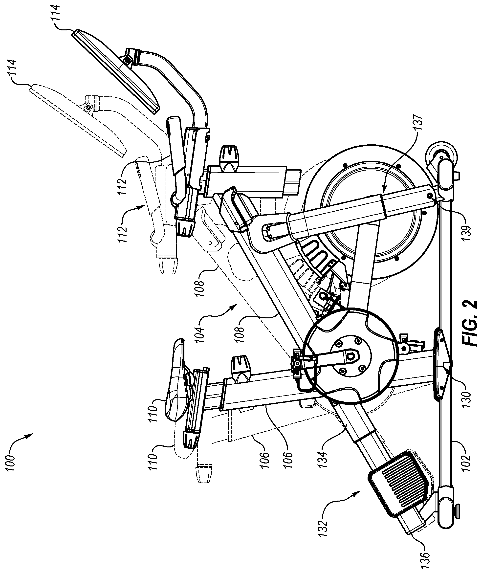
FIG. 2 is a side illustration of the exercise cycle of FIG. 1 with an upright frame shown in a forward tilted position, and a neutral position featured in phantom view;
FIG. 3 is another side illustration of the exercise cycle of FIG. 1 with the upright frame shown in a backward tilted position, and a neutral position featured in phantom view;
FIG. 4 is a perspective view of a portion of the exercise cycle of FIG. 1 showing a console pivot assembly;
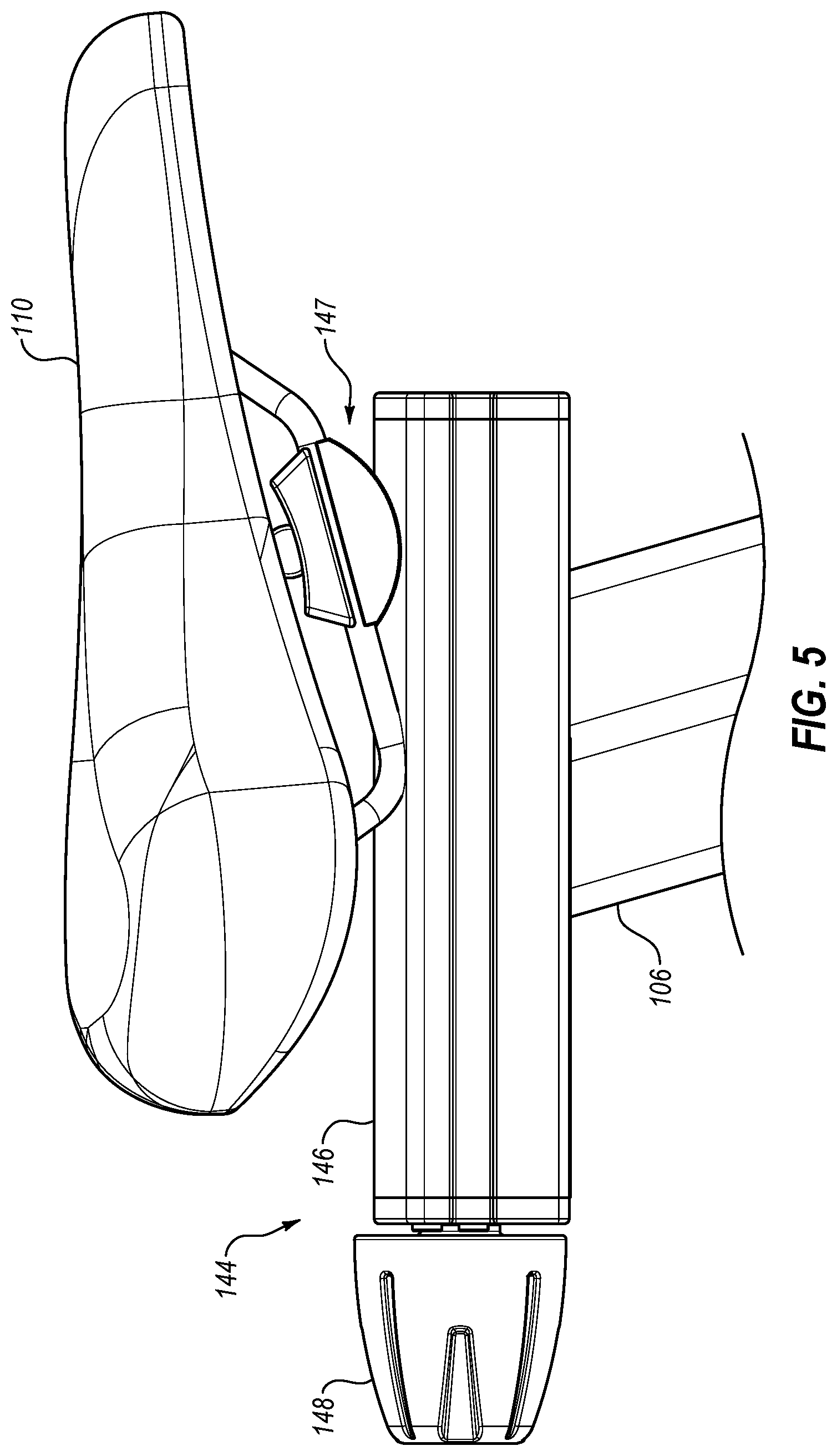
FIG. 5 is a side view of a seat adjustment mechanism;
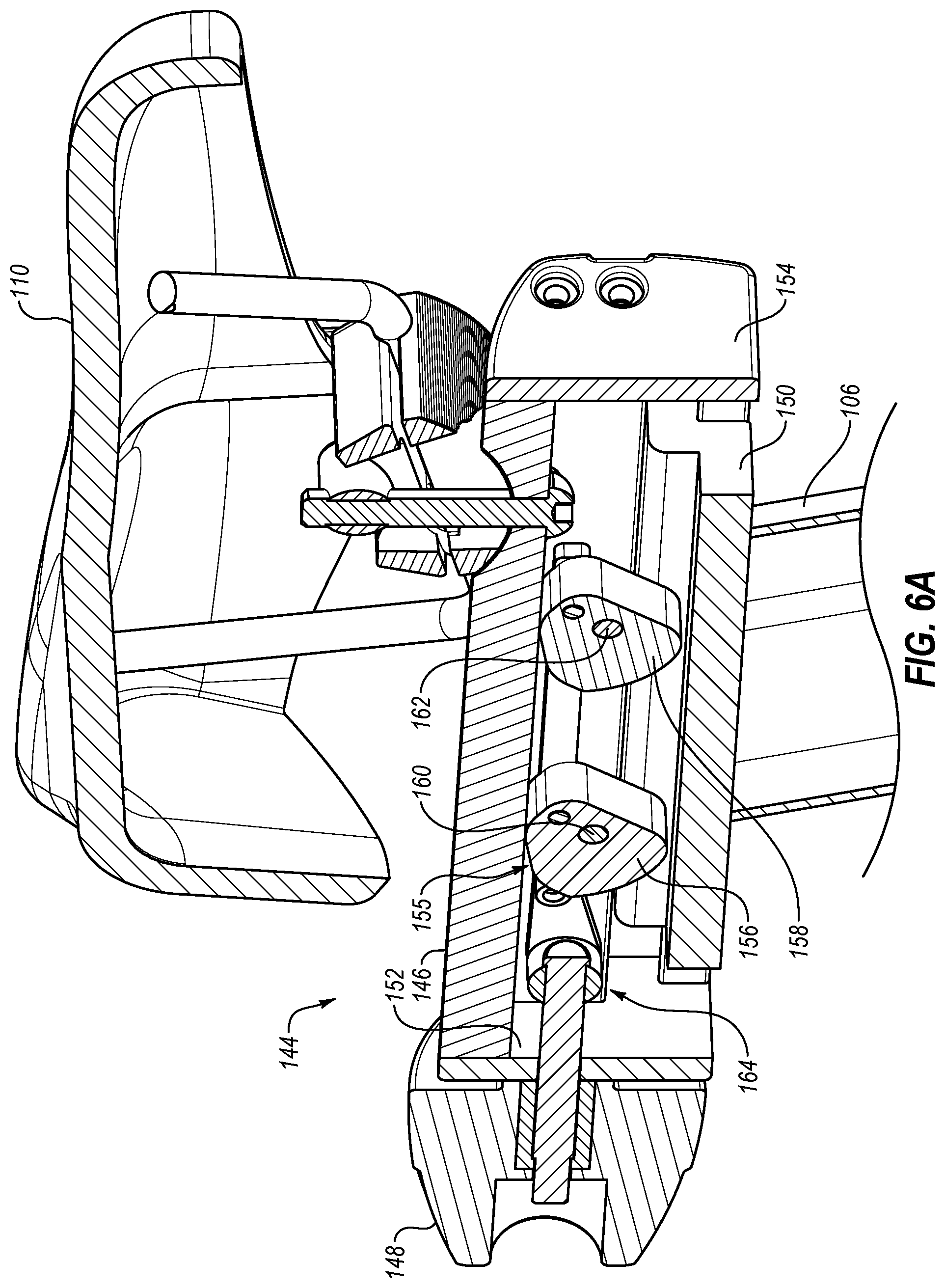
FIG. 6A is a side cross-sectional view of the seat adjustment mechanism of FIG. 5 in an unlocked configuration;
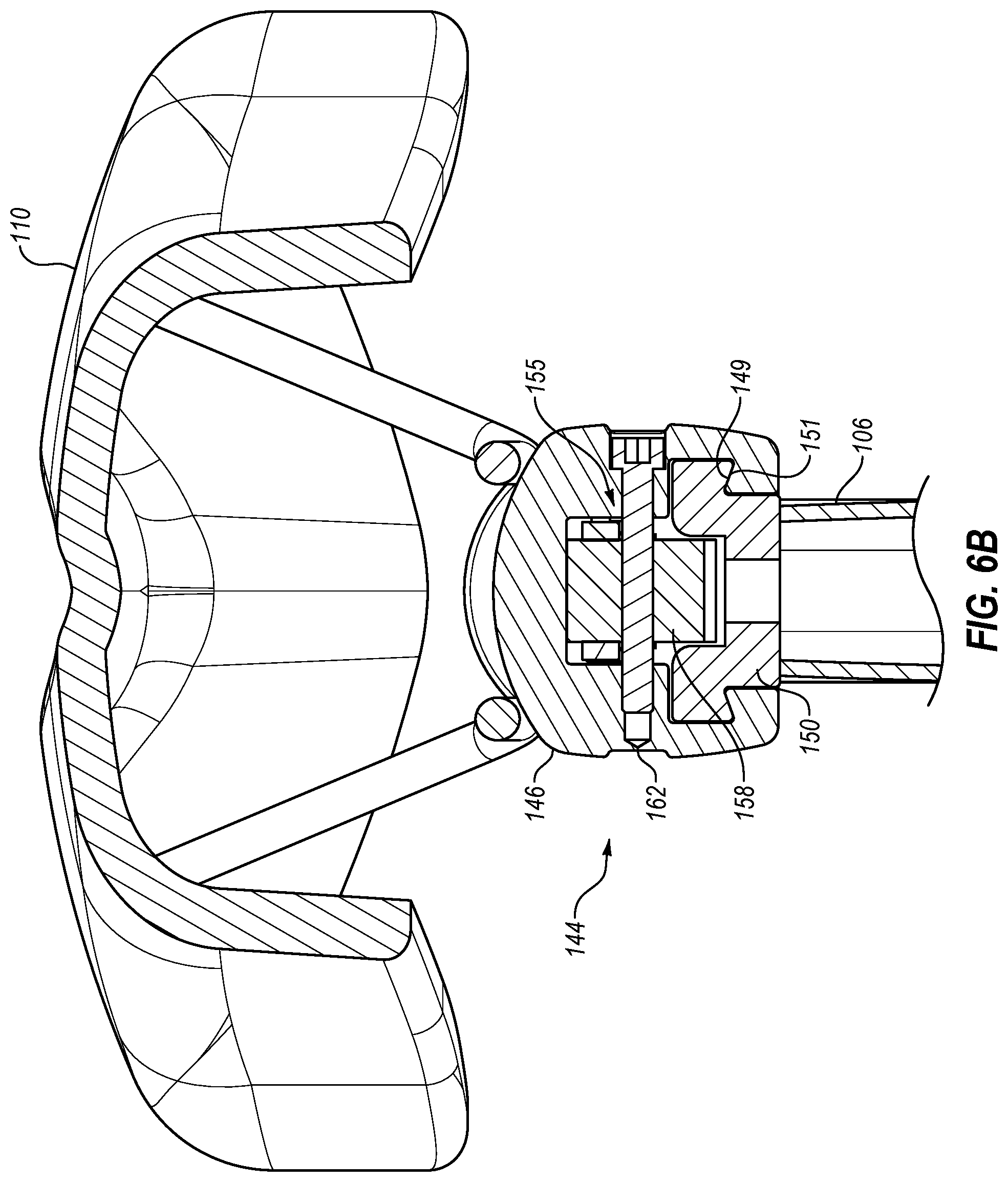
FIG. 6B is an end cross-sectional view of the seat adjustment mechanism of FIG. 5 in the unlocked configuration;
FIG. 7A is a side cross-sectional view of the seat adjustment mechanism of FIG. 5 in a locked configuration;
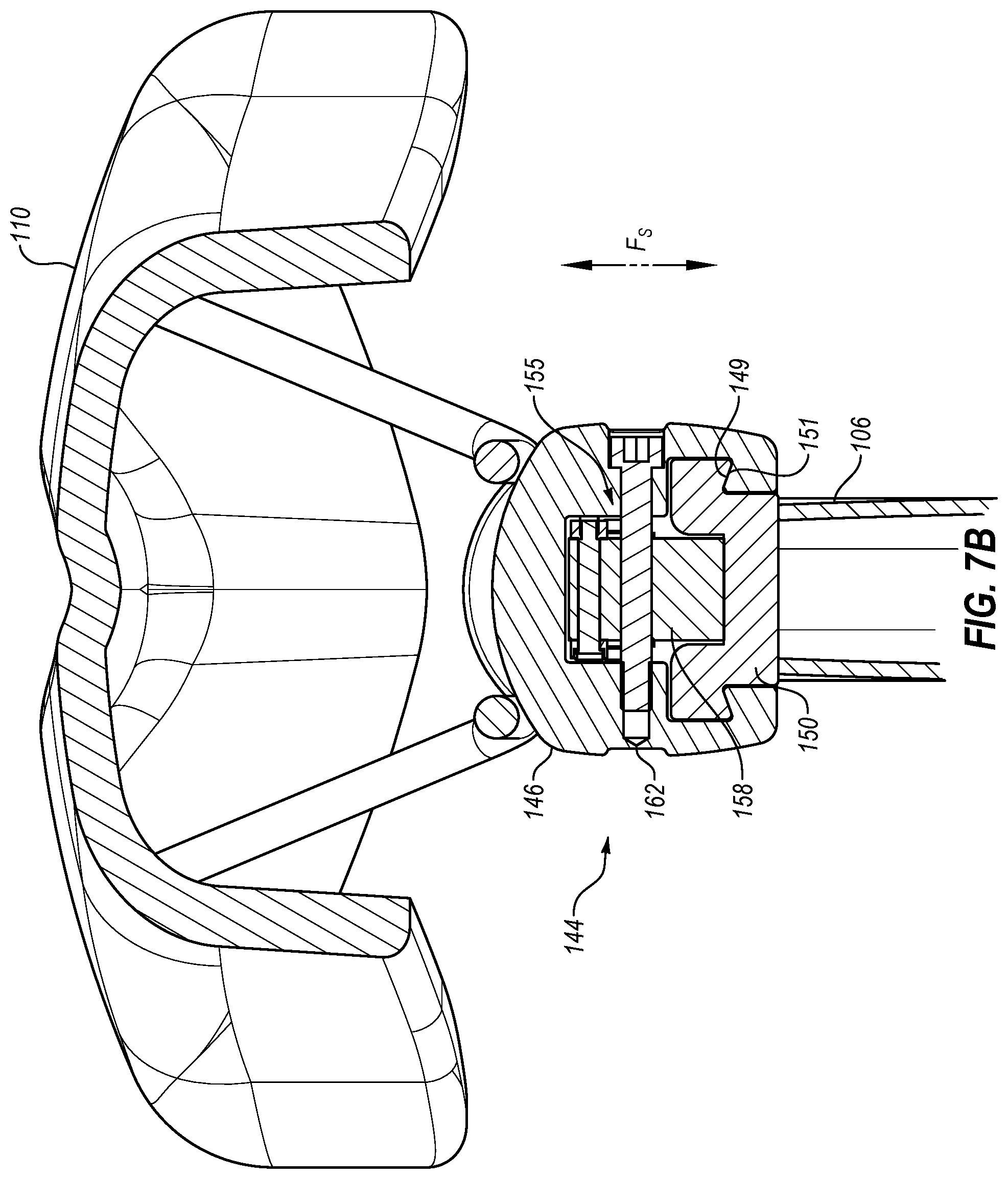
FIG. 7B is an end cross-sectional view of the seat adjustment mechanism of FIG. 5 in a locked configuration;
FIG. 8 is a side view of a handle adjustment mechanism;
FIG. 9 is a side cross-sectional view of the seat adjustment mechanism of FIG. 10; and
FIG. 10 is a side cross-sectional view of another adjustment mechanism.
DETAILED DESCRIPTION
In FIG. 1, an example stationary exercise cycle 100 is illustrated. Exercise cycle 100 includes a support base 102 and a generally upright support structure 104 pivotally coupled thereto. In the illustrated embodiment, upright support structure 104 includes two support members 106, 108, and may be referred to as a bicycle frame, although it need not look like, or act like, a bicycle frame of a road or mountain bicycle used in real-world cycling. Support member 106 of the illustrated embodiment includes a seat 110 upon which a user may sit when exercising on exercise cycle 100. Support member 108 includes a handle bar assembly 112 and a control panel or console 114.
In the illustrative embodiment, a drive assembly 116 is mounted on upright support structure 104. Drive assembly 116 includes a rotatable pedal assembly 118 having a pair of pedals 120, which a user can engage with his or her feet to rotate pedal assembly 118. Drive assembly 116 also includes, in this embodiment, a resistance assembly 122, which can affect the force required from the user to rotate pedal assembly 118. Resistance assembly 122 includes a flywheel 124, a resistance mechanism 126, and a motor 128. Resistance mechanism 126 and motor 128 are optionally each adapted to selectively adjust the force required to rotate pedal assembly 118. Thus, when a constant force is applied at pedal assembly 118, resistance mechanism 126 and/or motor 128 may vary the rotational speed of flywheel 124. In the illustrated embodiment, resistance mechanism 126 comprises a magnetic brake for controlling resistance to rotation of pedal assembly 118 and/or the rotational speed of flywheel 124.
Resistance assembly 122 is coupled to pedal assembly 118 such that the resistance provided to flywheel 124 by resistance mechanism 126 and/or motor 128 affects the resistance to the rotation of pedal assembly 1118. In other words, when a resistance is applied to flywheel 124, a braking force is present and it is generally more difficult for a user to rotate pedal assembly 118. Conversely, when little or no resistance is applied to flywheel 124, it is relatively easy for a user to rotate pedal assembly 118. By adjusting the amount of resistance applied to flywheel 124, exercise cycle 100 can thus vary the speed at which a user can pedal and/or the resistance experienced by the user as he or she pedals on exercise cycle 100. In this manner exercise cycle 100 is able to simulate the types of resistances, coasting, and pedaling speeds that a user may experience if riding a bicycle outdoors.
In addition to the ability to control and vary the speed and resistance of pedal assembly 118 and/or flywheel 124, exercise cycle 100 also permits varying the vertical pitch of the exercise cycle 100 by selectively tilting upright support structure 104 relative to the floor or other surface upon which exercise cycle 100 rests. As depicted in FIG. 2 in phantom lines, upright support structure 104 can be oriented in a neutral position. In the neutral position, the illustrated exercise cycle 100 may include handle bar assembly 112 and seat 110 at generally the same vertical distance from the floor or other support surface, although such is illustrative only, and the handle bar assembly 112 and seat 110 may be at different heights, even in the neutral position.
In this embodiment, when upright support structure 104 is in the neutral position, a user sitting on seat 110 may feel that he or she is sitting on a bicycle that is on a generally level surface. Additionally, as illustrated in solid lines in FIG. 2, upright support structure 104 can be oriented in a forwardly tilted position such that handle bar assembly 112 is vertically closer to the floor or other support surface relative to seat 110, and relative to the position of handle bar assembly 112 in the neutral position. This is achieved by adjusting the vertical pitch of upright support structure 104 relative to a floor or other support surface. Tilting upright support structure 104 forward as illustrated in FIG. 2 enables a user to simulate riding down a hill.
In one embodiment, such as that illustrated in FIG. 3, upright support structure 104 can also be oriented in a backwardly tilted position in which handle bar assembly 112 is vertically further from the floor or other support surface when compared to seat 110 or when compared to the position of handle bar assembly 112 in the neutral position. Typical bicycle rides outside involve inclines and declines as well as flat surfaces, each of which can be accommodated and replicated by the tilting ability of upright support structure 104. Thus, exercise cycle 100 is able to more closely simulate a typical outdoor bicycle ride.
The forward and backward tilting of upright support structure 104 to adjust the vertical pitch of support structure 104 can be accomplished through pivotally coupling upright support structure 104 to support base 102 as depicted in FIGS. 1-3. As seen in FIGS. 1-3, upright support structure 104 is connected to support base 102 by pivot 130. Pivot 130 allows upright support structure 104 to tilt forward and backward as described herein. Pivot 130 can include a pin that extends through a portion of support base 102 and through upright support structure 104.
While pivot 130 allows upright support structure 104 to tilt forward and backward, incline mechanism 132, or another linearly or otherwise extending assembly, controls the vertical pitch of upright support structure 104. In the illustrative embodiment, incline mechanism 132 is coupled between support base 102 and support member 106. More particularly, a first end 134 of incline mechanism 132 pivotally couples to support member 106 while a second end 136 of incline mechanism 132 pivotally couples to a rear portion of support base 102. In the illustrated embodiment, incline mechanism 132 is aligned with and/or generally parallel to support member 108. As a result, incline mechanism 132 extends and contracts in a direction that is generally in line with or parallel to an axis of support member 108.
The extension and contraction of incline mechanism 132 raises or lowers support member 106 relative to support base 102, thereby determining the vertical pitch and tilt of upright support structure 104 relative to the floor or other support surface. For instance, in one embodiment, upon contraction of incline mechanism 132, support member 106 is lowered, causing upright support structure 104 to tilt backward so that seat 110 is at a distance relative to the floor or other support surface that is below the position of seat 10 when at the neutral position. When incline mechanism 132 is selectively extended to an extended position, support member 106 is raised, causing upright support structure 104 to tilt forward so that seat 110 is vertically higher relative to seat 110 when at the neutral position. Through the forward and backward tilting of upright support structure 104, as described above, exercise cycle 100 is able to more closely simulate for a user the experience of riding a bicycle on level ground as well as up and down hills.
In the illustrated embodiment, the support base 102, the upright support structure 104, the pivot 130, and the incline mechanism 132 have unique spatial arrangements relative to one another. Some of the spatial arrangements provide improved performance or functionality to the exercise cycle 100. For instance, pivot 130 is disposed directly or substantially below the center of gravity of the upright support structure 104 and/or a user riding on exercise cycle 100. Such placement of pivot 130 can reduce or minimize the load supported by incline mechanism 132 and the force required of incline mechanism 132 to tilt upright support structure 104 as described herein.
In the illustrated embodiment, incline mechanism 132 is connect to support base 102 such that incline mechanism 132 and support base 102 form an angle of about 35.degree. when upright support structure 104 is in the neutral position described above. In some embodiments, when upright support structure 104 is in the neutral position, incline mechanism 132 and support base 102 form an angle of between about 10.degree. and about 80.degree., between about 20.degree. and about 70.degree., between about 25.degree. and about 45.degree., between about 25.degree. and about 60.degree., or any angle within the foregoing ranges.
Similarly, in the illustrated embodiment, support member 106 of upright support structure 104 is connect to support base 102 such that support member 106 and support base 102 form an angle of about 75.degree. when upright support structure 104 is in the neutral position described above. In some embodiments, when upright support structure 104 is in the neutral position, support member 106 and support base 102 form an angle of between about 25.degree. and about 90.degree., between about 35.degree. and about 85.degree., between about 45.degree. and about 80.degree., between about 60.degree. and about 80.degree., or any angle within the foregoing ranges.
Likewise, in the illustrated embodiment, support member 106 of upright support structure 104 is connect to incline mechanism 132 such that support member 106 and incline mechanism 132 form an angle of about 70.degree. when upright support structure 104 is in the neutral position described above. In some embodiments, when upright support structure 104 is in the neutral position, support member 106 and incline mechanism 132 form an angle of between about 25.degree. and about 90.degree., between about 35.degree. and about 85.degree., between about 45.degree. and about 80.degree., between about 60.degree. and about 80.degree., or any angle within the foregoing ranges.
As shown in FIGS. 1-3, exercise cycle 100 can also include a telescoping frame assembly 137. Telescoping frame assembly 137 is connected between upright support structure 104 and support base 102. More specifically, telescoping frame assembly 137 is connected between support member 108 and a forward end of support base 102. As upright support structure 104 tilts forward or backward, telescoping frame assembly 137 contracts or extends. Additionally, telescoping frame assembly 137 can also pivot relative to support base 102 when upright support structure 104 tilts forward or backward. To accommodate the pivoting of telescoping frame assembly 137, telescoping frame assembly 137 can be connected to support base 102 by a pivot connection 139. In some embodiments, telescoping frame assembly 137 provides load-bearing support to upright support structure 104.
As noted above in connection with FIG. 1, exercise cycle 100 includes a console 114. Console 114 can include a controller that controls one or more operational aspects of exercise cycle 100. For instance, the controller can control resistance mechanism 126 and/or motor 128 to increase or decrease the resistance to the rotation of pedal assembly 118. Likewise, the controller can control incline mechanism 132 to increase or decrease the forward and backward tilting of upright support structure 104.
Console 114 also includes one or more interface devices. Such interface devices may be either input devices or output devices. Input devices (e.g., buttons, sliders, touchscreens, etc.) enable a user to input and vary the operating parameters (resistance, speed, incline, time, distance, program selection, heart rate controls, etc.) of the exercise cycle 100. The output devices (e.g., lights, speakers, digital displays, video displays, etc.) can provide the user with information about the operation of exercise cycle 100, entertainment (e.g., music, radio, video, internet, etc.), and the like.
Additionally, the output devices may provide instructions (e.g., video, text, audio, etc.) to a user regarding exercises that are performed separate from exercise cycle 100. For instance, as illustrated in FIG. 4, console 114 may be movably connected to upright support structure 104 so that console 114 can be rotated for viewing by a user that is not sitting on exercise cycle 100. The movable connection between console 114 and upright support structure 104 is provided by a pivot assembly 138. In the illustrated embodiment, pivot assembly 138 enables console 114 to pivot or rotate about two axes. In particular, pivot assembly 138 includes a horizontal pivot 140 that enables console 114 to pivot or rotate in a generally horizontal plane, such that console 114 pivots or rotates about a generally vertical axis A.sub.1.
In the present embodiment, horizontal pivot 140 enables console 114 to pivot or rotate more than 90.degree. in one direction. In particular, from a neutral position where console 114 faces seat 110, horizontal pivot 140 enables console 114 to pivot or rotate more than 90.degree. about axis A.sub.1 in one direction. In some embodiments, horizontal pivot 140 enables console 114 to rotate about axis A.sub.1 more than 90.degree. in two opposite directions from the neutral position. Thus, in some embodiments, console 114 can pivot or rotate about axis A.sub.1 more than a total of 180.degree.. In other embodiments, console 114 can pivot or rotate up to or more than 180.degree. about axis A.sub.1 in two opposite directions from a neutral position. In such embodiments, console 114 may be able to pivot or rotate up to or more than 360.degree. about axis A.sub.1.
In the illustrated embodiment, the pivot assembly 138 also includes a vertical pivot 142 that enables console 114 to pivot or rotate in a generally vertical plane, such that console 114 pivots or rotates about a generally horizontal axis A.sub.2. In the present embodiment, vertical pivot 142 enables console 114 to pivot or rotate at least than 180.degree. about axis A.sub.2. In particular, from a neutral position where console 114 faces seat 110, vertical pivot 142 enables console 114 to pivot or rotate at least 180.degree. about axis A.sub.2 so that console 114 faces away from seat 110.
Attention is now directed to FIGS. 5-7B, which illustrate a seat adjustment mechanism 144 that enables the position of seat 110 to be selectively adjusted forward and backward. As can be seen in FIG. 5, seat adjustment mechanism 144 includes a housing or frame 146 (as referred to herein as sliding frame 146) on which seat 110 is mounted. In some embodiments, such as that illustrated in FIG. 5, seat 110 can be adjustably mounted to housing or frame 146 by a tilting mechanism 147 to enable seat 110 to be selectively tilted forward or backward (e.g., to raise or lower the front or rear portions of seat 110) as desired by a user.
Seat adjustment mechanism 144 also includes an adjustment knob 148 which, as discussed below, can be used to engage or disengage a locking mechanism of seat adjustment mechanism 144 and/or adjust the position of sliding frame 146 and seat 110. As also discussed below, when the locking mechanism is engaged, sliding frame 146 and seat 110 are secured in place. In contrast, when the locking mechanism is disengaged, sliding frame 146 and seat 110 can be selectively moved forward or backward relative to upright support structure 104 or support member 106 thereof. The ability to adjust the forward or backward position of seat 110 enables a user to adjust exercise cycle 100 to accommodate the user's particular desires or needs (e.g., size).
With particular attention to FIGS. 6A-7B, seat adjustment mechanism 144 is shown in cross-section. FIGS. 6A and 7A show side cross-sectional views of seat adjustment mechanism 144, while FIGS. 6B and 7B show end cross-sectional views thereof. As can be seen, seat adjustment mechanism 144 includes a guide frame 150 disposed at the upper end of support member 106. Guide frame 150 is maintained in a fixed position relative to support member 106. In contrast, sliding frame 146 is slidably associated with guide frame 150. More specifically, sliding frame 146 and guide frame 150 include cooperating features that enable sliding frame 146 to slide linearly relative to guide frame 150. Such cooperating features can include mating surfaces, such as dovetail surfaces 149, 151 best seen in FIGS. 6B and 7B. The sliding of sliding frame 146 relative to guide frame 150 repositions seat 110 relative to support member 106 and other portions of exercise cycle 100 (e.g. handle bar assembly 112).
To facilitate the sliding of sliding frame 146 and seat 110 forward and backward relative to guide frame 150, sliding frame 146 may be longer than the guide frame 150. Thus, as can be seen in FIGS. 6A and 7A, sliding frame 146 can extend forwardly from and/or backwardly from guide frame 150. In some embodiments, the difference in length between sliding frame 146 and guide frame 150 can be between about 2 inches and about 12 inches, or any length therebetween. As a result, the position of seat 110 can be adjusted forward or backward a distance of between about 2 inches and about 12 inches, or any length therebetween.
In some embodiments, including the embodiment illustrated in FIGS. 6A and 7A, seat adjustment mechanism 144 includes one or more stops that limit the travel of sliding frame 146 and seat 110. For instance, disposed on opposing ends of sliding frame 146 are end caps 152, 154. End caps 152, 154 can be arranged and configured so as to engage guide frame 150 once sliding frame 146 has reached a maximum forward or rearward position. By way of example, end cap 152 can engage guide frame 150 when sliding frame 146 and seat 110 have been moved to a forward most position. Similarly, end cap 154 can engage guide frame 150 when sliding frame 146 and seat 110 have been moved to a rearward most position. End caps 152, 154 can also prevent sliding frame 146 from being inadvertently removed or disengaged from guide frame 150.
As mentioned above and illustrated in FIGS. 6A-7B, seat adjustment mechanism 144 also includes a locking mechanism 155. In the illustrated embodiment, the locking mechanism 155 includes first and second cams 156, 158 disposed between sliding frame 146 and guide from 150. Cams 156, 158 are pivotally or rotatably mounted to sliding frame 146. More specifically, first cam 156 is pivotally or rotatably mounted on a rod 160 and second cam 158 is pivotally or rotatably mounted on a rod 162. Rods 160, 162 are connected between opposing walls of sliding frame 146. FIGS. 6B and 7B illustrate the connection between sliding frame 146, cam 158, and rod 162. The connection between sliding frame 146, cam 156, and rod 160 is substantially identical.
Cams 156, 158 are connected to knob 148 by a linkage 164. More specifically, knob 148 is connected to a first end of linkage 164, cam 156 is connected at an intermediate location along the length of linkage 164, and cam 158 is connected near a second end of linkage 164. Knob 148 and linkage 164 are connected together such that movement of knob 148 results in a similar movement of linkage 164. For instance, if knob 148 is moved away from sliding frame 146 (e.g., in a rearward direction), linkage 164 will similarly move is a rearward direction. Likewise, if knob 148 is moved toward sliding frame 146 (e.g., in a forward direction), linkage 164 will similarly move in a forward direction.
Cams 156, 158 and linkage 164 are connected such that movement of linkage 164 causes cams 156, 158 to rotate or pivot about rods 160, 162. For instance, when linkage 164 is moved in a first direction (e.g., forward) by way of moving knob 148 in the first direction (e.g., towards sliding frame 146), linkage 164 causes cams 156, 158 to pivot or rotate about rods 160, 162 in a first direction. Similarly, when linkage 164 is moved in a second direction (e.g., rearward) by way of moving knob 148 in the second direction (e.g., away from sliding frame 146), linkage 164 causes cams 156, 158 to pivot or rotate about rods 160, 162 in a second direction.
For instance, FIG. 6A illustrates knob 148 moved towards sliding frame 146 (e.g., in a forward direction). Such movement of knob 148 causes linkage 164 to likewise move in a forward direction, which causes cams 156, 158 to pivot or rotate about rods 160, 162. In the illustrated embodiment, linkage 164 is connected to cams 156, 158 above rods 160, 162. Accordingly, when linkage 164 moves in the forward direction, the upper portions of cams 156, 158 also move in a forward direction.
When knob 148 is moved towards sliding frame 146 as shown in FIG. 6A, cams 156, 158 are rotated so as to be oriented at least partially in the horizontal direction. More specifically, each of cams 156, 158 is shaped so as to have a first dimension that is larger than a second dimension. When cams 156, 158 are rotated to the position shown in FIG. 6A, the first dimension of each of the cams 156, 158 is oriented so that the first dimension extends at least partially in the horizontal direction and does not extend in a generally perpendicular manner between sliding frame 146 and guide frame 150.
When cams 156, 158 are rotated as shown in FIG. 6A, locking mechanism 155 is in an unlocked configuration. More specifically, rotation of cams 156, 158 to the position shown in FIG. 6A removes all or a significant portion of a spreading force applied between sliding frame 146 and guide frame 150. For instance, in some embodiments, cams 156, 158 do not contact or otherwise engage the guide frame 150 when the locking mechanism 155 is in the locked configuration. In other embodiments, the cams 156, 158 may contact or otherwise engage the guide frame 150 when the locking mechanism 155 is in the locked configuration while applying a limited spreading force between the sliding frame 146 and the guide frame 150. In any event, when the locking mechanism 155 is in the unlocked configuration, the friction between the sliding frame 146 and the guide frame 150 is reduced sufficiently to enable sliding frame 146 to slide relative to the guide frame 150, thereby allowing the position of the seat 110 to be selectively adjusted.
Locking mechanism 155 can also be placed in a locked configuration. According to the illustrated embodiment, locking mechanism 155 is moved from the unlocked configuration to the locked configuration by moving knob 148 away from sliding frame 146 (e.g., in a rearward direction) to the position shown in FIG. 7A. Such movement of knob 148 causes linkage 146 to likewise move in a rearward direction. Rearward movement of linkage 146 causes cams 156, 158 to pivot or rotate about rods 160, 162 such that the upper portions of cams 156, 158 also move in a rearward direction. Such rotation causes cams 156, 158 to be oriented more vertically (e.g., the first dimension is oriented more perpendicular relative to sliding frame 146 and guide frame 150).
Rotation of cams 156, 158 to a more vertical orientation as shown in FIG. 7A causes cams 156, 158 to contact or otherwise engage guide frame 150 in a manner that applies a spreading force between sliding frame 146 and guide frame 150. As illustrated in FIG. 7B, the spreading force F.sub.s urges sliding frame 146 and guide frame 150 away from one another. The spreading force F.sub.s causes dovetail surfaces 149, 151 to be pressed into closer contact with one another. The closer contact between dovetail surfaces 149, 151 increases the friction therebetween, which resists movement of sliding frame 146 relative to guide frame 150. As a result, seat 110 is selectively secured in place when locking mechanism 155 is in the locked configuration. In contrast, when locking mechanism 155 is in the unlocked configuration (FIGS. 6A and 7A), cams 156, 158 create no or a minimal spreading force between sliding frame 146 and guide frame 150, thereby reducing the friction between dovetail surfaces 149, 151. The reduced friction allows sliding frame 146 to move relative to guide frame 150, which allows seat 110 to be selectively repositioned as desired.
As can be seen in FIGS. 6A and 7A, cams 156, 158 are spaced apart from one another between the front and rear ends of seat adjustment mechanism 144. Such spacing can provide stability to seat adjustment mechanism 144 and seat 110. In particular, spacing cams 156, 158 apart from one another can limit or prevent sliding frame 146 from teetering or rocking, thereby holding seat 110 in a more secure and stable position. In the illustrated embodiment, cams 156, 158 are spaced apart by about 2.5 inches. In other embodiments, cams 156, 158 can be spaced apart by between about 1 inch and about 12 inches, between about 2 inches and about 10 inches, between about 1.5 inches and about 6 inches, or any distance within the foregoing ranges.
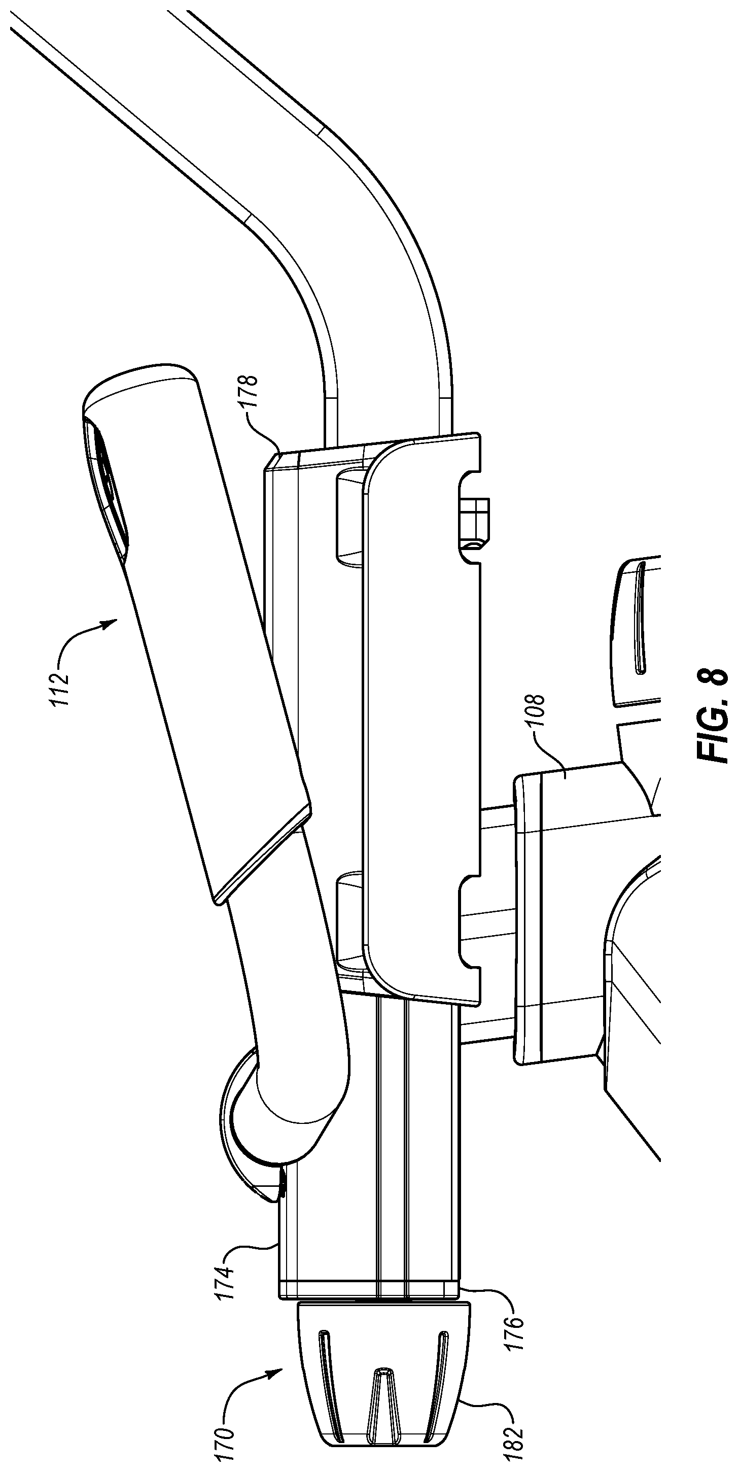
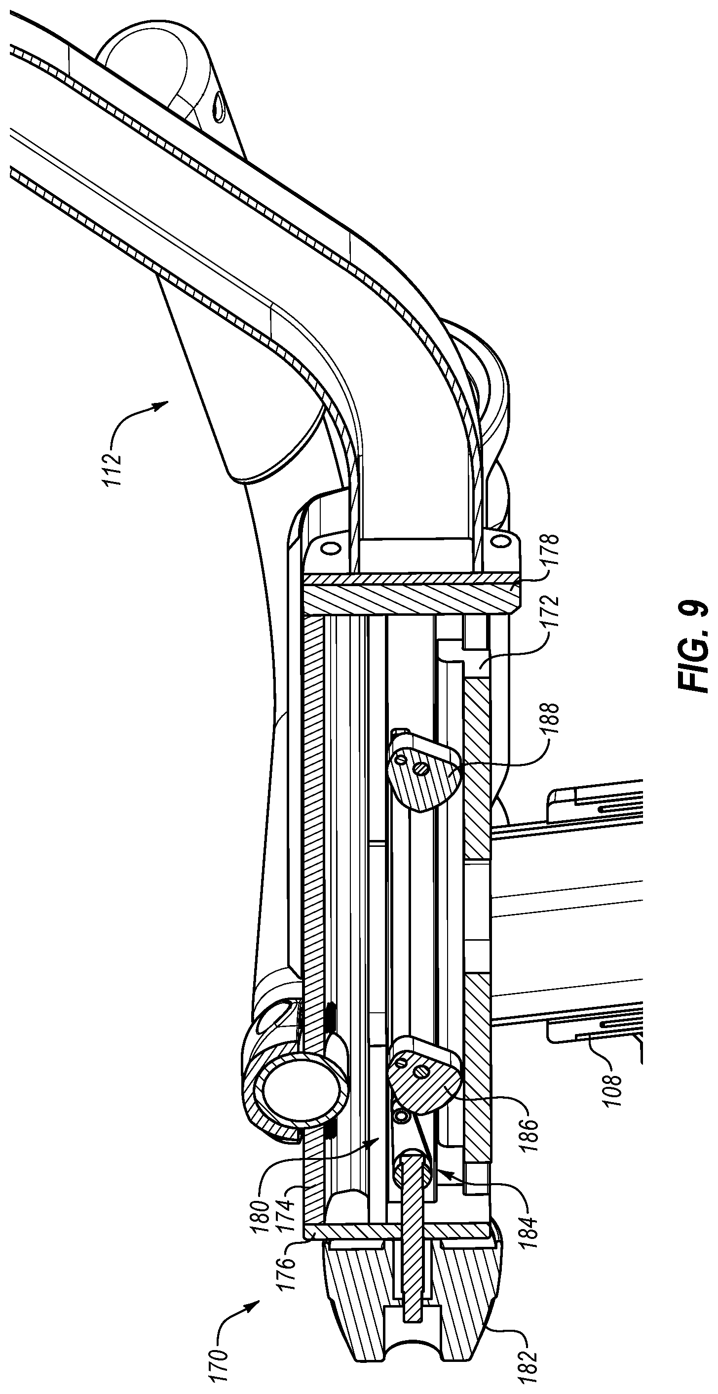
Attention is now directed to FIGS. 8 and 9, which illustrate a handle bar adjustment mechanism 170. In particular, FIG. 8 illustrates a side view of handle bar adjustment mechanism 170 and FIG. 9 illustrates a side cross-sectional view thereof. Handle bar adjustment mechanism 170 enables handle bar assembly 112 to be selectively repositioned forward or backward similar to the adjustment of seat 110 discussed above. Additionally, other than having handle bar assembly 112 mounted thereon instead of seat 110, handle bar adjustment mechanism 170 can be similar or identical to seat adjustment mechanism 144 discussed above.
For instance, handle bar adjustment mechanism 170 includes a guide frame 172 mounted on support member 108 is a fixed manner. Handle bar adjustment mechanism 170 also includes a sliding frame 174 movably or slidably mounted on guide frame 172. Sliding frame 174 includes end caps 176, 178 disposed at opposing ends thereof to limit the travel of sliding frame 174 relative to guide frame 172 and/or to prevent removal of sliding frame 174 from guide frame 172.
Handle bar adjustment mechanism 170 also includes a locking mechanism 180 that can be moved between a locked configuration and an unlocked configuration. When locking mechanism 180 is in the locked configuration, sliding frame 174 is secured in place relative to guide frame 172. As a result, handle bar assembly 112 is also secured in place. In contrast, when locking mechanism 180 is in the unlocked configuration, sliding frame 174 is able to move relative to guide frame 172. Movement of handle bar assembly 112 is directly linked to movement of sliding frame 174. Thus, movement of sliding frame 174 repositions handle bar assembly 112. Once handle bar assembly 112 is (re)positioned as desired, locking mechanism 180 can be moved to the locked configuration to secure handle bar assembly 112 is the desired position.
Similar to locking mechanism 155 of seat adjustment mechanism 144, locking mechanism 180 includes a knob 182, a linkage 184, and cams 186, 188. Cams 186, 188 are disposed between guide frame 172 and sliding frame 174 and are connected to knob 182 by linkage 184. Knob 182 can be moved relative to sliding frame 174, which moves linkage 184 and rotates cams 186, 188.
When locking mechanism 180 is in the locked configuration, cams 186, 188 are rotated to apply a spreading force against guide frame 172 and sliding frame 174. The spreading force increases the friction between guide frame 172 and sliding frame 174, thereby restricting movement of sliding frame 174 relative to guide frame 172. In contrast, when locking mechanism 180 is in the unlocked configuration, cams 186, 188 are rotated to remove or reduce the spreading force applied between guide frame 172 and sliding frame 174. The reduced spreading force reduces the friction between guide frame 172 and sliding frame 174, thereby allowing sliding frame 174 (and connected handle bar assembly 112) to move relative to guide frame 172.
As can be seen in FIG. 11, cams 186, 188 are spaced apart from one another between the front and rear ends of handle bar adjustment mechanism 170. Such spacing can provide stability to handle bar adjustment mechanism 170 and handle bar assembly 112. In particular, spacing cams 186, 188 apart from one another can limit or prevent sliding frame 174 from teetering or rocking, thereby holding handle bar assembly 112 in a more secure and stable position. In the illustrated embodiment, cams 186, 188 are spaced apart by about 2.5 inches. In other embodiments, cams 186, 188 can be spaced apart by between about 1 inch and about 12 inches, between about 2 inches and about 10 inches, between about 1.5 inches and about 6 inches, or any distance within the foregoing ranges.
Attention is now directed to FIG. 110, which illustrates an adjustment mechanism 190 that is similar to adjustment mechanisms 144 and 170 discussed herein. Because adjustment mechanism 190 is similar or identical to adjustment mechanisms 144 and 170 in many respects, the following discussion will focus on the unique aspects of adjustment mechanism 190. Before proceeding further, it will be noted that while adjustment mechanism 190 is shown connected between a seat 192 and a support member 194 similar to adjustment mechanism 144, adjustment mechanism 190 may similarly be connected between a support member and a handle bar assembly similar to adjustment mechanism 170.
Adjustment mechanism 190 includes a guide frame 196 and a sliding frame 198 that can be similar or identical to the other guide frames and sliding frames described herein. Adjustment mechanism 190 also includes a locking mechanism 200 for selectively securing sliding frame 198 in place relative to guide frame 196. Locking mechanism 200 includes an adjustment knob 202, a linkage 204, and a cam 206. Cam 206 is rotatable between a locked position and an unlocked position to either apply or remove a spreading force from guide frame 196 and sliding frame 198.
One distinction between adjustment mechanism 190 and the other adjustment mechanism described herein is that adjustment mechanism 190 includes a single cam 206, rather than multiple spaced apart cams. Additionally, cam 206 is moved between the unlocked and locked positions by rotation of knob 202, rather than through linear movement as with the other adjustment mechanisms described herein. In the illustrated embodiment, linkage 204 includes a lead screw 208 and a follower 210. Lead screw 208 and knob 202 are connected such that rotation of knob 202 results in a corresponding rotation of lead screw 208. Following 210 is mounted on lead screw 208 such that rotation of lead screw 208 causes follower 210 to move linearly. In turn, follower 210 is connected to cam 206 such that linear movement of follower 210 causes cam 206 to rotate between the locked and unlocked positions.
INDUSTRIAL APPLICABILITY
In general, embodiments of the present disclosure relate to exercise cycles that can be selectively adjusted to accommodate different exercises or users. For instance, an exercise cycle may have an adjustable incline mechanism for allowing a portion of the exercise cycle to have a forward incline simulating a descent down a hill, or a rear incline to simulate an ascent up a hill. By way of example, the exercise cycle can include an upright support structure pivotally connected to a support base. An incline mechanism connected between the support base and the upright support structure can cause the upright support structure to pivot between various tilted and neutral positions.
In some embodiments, the upright support structure includes first and second support members. In some cases, the first support member has a seat mounted thereon and the second support member has a set of handles or a handle bar assembly mounted thereon. Additionally, in some embodiments, the first support member is pivotally connected to the base support, while the second support member is connected to and extends from the first support member. In some cases, the pivotal connection between the upright support structure and/or the first support member thereof and the support base includes one or more stops to limit the tilting of the upright support structure within a desired range. Pivotal connection can, in some embodiments, include a ball joint allowing the upright support structure to tilt forward or backward relative to the floor or other support surface, or even tilt from side-to-side.
The incline mechanism can be connected between the support base and the first support member such that the incline mechanism can apply forces therebetween to pivot the upright support structure relative to the support base. The incline mechanism can be any linearly extending mechanism, such as a rotating or threaded drive shaft, a rod and piston assembly or other pneumatic or hydraulic actuator, a rack and pinion assembly, or any other extension mechanism.
In some embodiments, the incline mechanism is pivotally connected to one or both of the support base and the upright support structure (or the first support member thereof). Additionally, the incline mechanism can be connected between the support base and the upright support structure such that the incline mechanism and the second support member are generally aligned with one another or extend generally parallel to one another.
The exercise cycle can also include a resistance mechanism that increases or decreases the effort required of the user to rotate the pedals of the exercise cycle. The resistance mechanism can take a variety of forms. For instance, the resistance mechanism may include a magnetic brake (e.g., eddy brake), a frictional brake, an electromechanical brake, or any other suitable mechanism.
In some embodiments, the support base, the upright support structure, the pivot, and the incline mechanism have unique spatial arrangements relative to one another. Some of the spatial arrangements provide improved performance or functionality to the exercise cycle. For instance, a pivot is disposed directly or substantially below the center of gravity of the upright support structure and/or a user riding on exercise cycle. Such placement of the pivot can reduce or minimize the load supported by an incline mechanism and the force required of the incline mechanism to tilt the upright support structure.
In some embodiments, an incline mechanism is pivotally connected to the support base such that the incline mechanism and the support base form an angle of about 35.degree. when upright support structure is in the neutral position described above. In some embodiments, when upright support structure is in the neutral position, incline mechanism and support base form an angle of between about 10.degree. and about 70.degree., between about 20.degree. and about 60.degree., between about 25.degree. and about 55.degree., between about 30.degree. and about 50.degree., or any angle within the foregoing ranges.
Similarly, the support member of the upright support structure may be connected to the support base such that the support member and the support base form an angle of about 75.degree. when upright support structure is in the neutral position described above. In some embodiments, when upright support structure is in the neutral position, the support member and the support base form an angle of between about 25.degree. and about 90.degree., between about 35.degree. and about 85.degree., between about 45.degree. and about 80.degree., between about 60.degree. and about 80.degree., or any angle within the foregoing ranges.
Further, the support member of the upright support structure may be connected to the incline mechanism such that the support member and the incline mechanism form an angle of about 70.degree. when the upright support structure is in the neutral position described above. In some embodiments, when the upright support structure is in the neutral position, the support member and incline mechanism form an angle of between about 25.degree. and about 90.degree., between about 35.degree. and about 85.degree., between about 45.degree. and about 80.degree., between about 60.degree. and about 80.degree., or any angle within the foregoing ranges.
In some embodiments, the exercise cycle can include a console that can be used while riding on the exercise cycle or while performing other activities not on the exercise cycle. For instance, the console can be adjustably connected to the upright support structure so that a user on the exercise cycle can adjust the orientation of the console to a position or angle desirable for viewing while the user is riding on the exercise cycle. Such adjustments may include tilting the console up or down (e.g., to remove glare, etc.).
The console can also be adjustably connected to the upright support structure so that a user can rotate the console for use when the user is not riding on the exercise cycle. For instance, the user may rotate the console in a horizontal plane or about a vertical axis so that the console faces away from a seat on the exercise cycle. When the console is rotated away from the seat, the user can view content on the console while the user performs other activities.
For instance, an exercise routine may call for the user to ride on the exercise cycle for a specified time or distance. The exercise routine may also call for the user to perform one or more exercises other than riding on the exercise cycle. Such exercises may include aerobic exercises, strength training exercises, balance exercises, and the like. In some cases, the console may provide instructions to the user for performing the additional exercises. To enable the user to view the instructions while performing the exercises, the console can be rotated away from the exercise cycle seat and towards an area adjacent to the exercise cycle where the user can perform the exercises.
Example exercise cycles also allow for the adjustment of the exercise cycle seat and/or handles/handle bar assembly. For instance, an exercise cycle can include an adjustment mechanism for the seat, an adjustment mechanism for the handles/handle bar assembly, or an adjustment mechanism for each of the seat and the handles/handle base assembly. In some cases, the adjustment mechanisms for the seat and the handles/handle bar assembly can be substantially identical to one another.
Such adjustment mechanism can include a guide frame fixedly mounted on the upright support structure. A sliding frame can be slidably mounted on the guide frame for movement between forward and rearward positions relative to the guide frame. The seat or handles/handle bar assembly (depending on whether the adjustment mechanism is used with the seat or the handles/handle bar assembly) can be secured to the sliding frame such that movement of the sliding frame results in movement of the seat or handles/handle bar assembly.
The adjustment mechanism can include a locking mechanism that selectively secures the sliding frame (and the associated seat or handles/handle bar assembly) in place or allows the sliding frame (and the associated seat or handles/handle bar assembly) to be moved to a desired position. The locking mechanism can include one or more cams disposed between the sliding frame and the guide frame. In some embodiments, the one or more cams are pivotally or rotatably connected to the sliding frame. In other embodiments, the one or more cams are pivotally connected to the guide frame.
Connected to the one or more cams are a linkage and a knob. The one or more cams are pivotally connected to the linkage such that movement of the linkage causes the one or more cams to rotate. The linkage, in turn, is connected to the knob such that movement of the knob results in movement of the linkage and the one or more cams. In some embodiments, the knob moves linearly (e.g., in a sliding manner) to move the linkage and the one or more cams. In other embodiments, the knob can be rotated to cause the movement of the linkage and the one or more cams. For instance, the knob and the linkage may be connected with a lead screw and follower. Rotation of the knob may rotate the lead screw, which in turn moves the follower and the linkage linearly and causes the one or more cams to rotate.
The one or more cams can be rotated between locked and unlock positions. In the locked position, the one or more cams engage the guide frame and the sliding frame in a manner that applies a spreading force therebetween. The spreading force causes the cooperating features, such as mating dovetails surfaces, of the guide frame and the sliding frame to be pressed into closer contact with one another. The closer contact between the cooperating features increases the friction therebetween, thereby restricting movement of the sliding frame (and the associated seat or handles/handle bar assembly) relative to the guide frame.
In contrast, when the one or more cams are rotated to the unlocked position, the spreading force applied by the one or more cams to the guide frame and the sliding frame is reduced or eliminated. As a result, the friction between the cooperating features is also reduced or eliminated, thereby allowing the sliding frame (and the associated seat or handles/handle bar assembly) to move relative to the guide frame.
As noted, the locking mechanism can include one or more cams. The use of a single cam can adequately secure the sliding frame (and the associated seat or handles/handle bar assembly) in place. In some instances, however, it can be desirable to use two or more cams as part of the locking mechanism. Using two or more cams can limit or prevent the sliding frame (and the associated seat or handles/handle bar assembly) from teetering, deflecting, bending, flexing, or rocking (e.g., relative to the cam or the guide frame). Additionally, using two or more cams can improve the connection between the guide frame and the sliding frame. Furthermore, using two or more cams can increase and/or more evenly distribute the spreading force applied between the guide frame and the sliding frame along the length of the guide frame and the sliding frame. The distribution of the spreading force can extend the life of the components by minimizing or preventing localized stresses during use of the exercise cycle.
In embodiments that include a first cam and a second cam, the cams may be spaced apart from one another between the front and rear ends of the seat or handle bar adjustment mechanism. Such spacing may provide improved stability to the seat or handle bars relative to the frame. In other words, proper spacing of the cams apart from one another can limit or prevent the sliding frame from teetering or rocking, thereby holding the seat or handle bars in a more secure and stable position. In some embodiments, the cams may be spaced apart by about 2.5 inches. In other embodiments, the first and second cams may be spaced apart by between about 1 inch and about 12 inches, between about 2 inches and about 6 inches, between about 1.5 inches and about 4 inches, or any distance within the foregoing ranges.
Alternatively, the adjustment mechanism may include a single cam, rather than multiple spaced apart cams.
In general, embodiments of the invention may be described as outlined in the following sections.
1. An exercise cycle, comprising:
a frame configured to rest upon a support surface;
at least one of: a handle bar assembly configured to be held during use of the exercise cycle, the handle bar assembly being connected to the frame; or a seat configured to support a user during use of the exercise cycle, the seat being connected to the frame; and
an adjustment mechanism for selectively adjusting the position of the handle bar assembly or the seat relative to the frame, the adjustment mechanism comprising: a guide frame fixedly secured to the frame; a sliding frame slidably mounted on the guide frame, the handle bar assembly or the seat being mounted on the sliding frame; and one or more cams pivotally disposed between the guide frame and the sliding frame, the one or more cams being rotatable between an unlocked position and a locked position, the one or more cams restricting movement of the sliding frame when the one or more cams are in the locked position and allowing the sliding frame to move relative to the guide frame when the one or more cams are in the unlocked position. 2. An exercise cycle as outlined in section 1, wherein the adjustment mechanism further comprises a linkage and an adjustment knob. 3. An exercise cycle as outlined in section 2, wherein the one or more cams are pivotally connected to the linkage. 4. An exercise cycle as outlined in any of sections 1-3, wherein the knob can be selectively engaged to cause the one or more cams to rotate between the locked and unlocked positions. 5. An exercise cycle as outlined in any of sections 1-4, wherein the handle bar assembly or the seat is fixedly secured to the sliding frame such that movement of the sliding frame results in corresponding movement of the handle bar assembly or the seat. 6. An exercise cycle as outlined in any of sections 1-5, wherein the one or more cams include a first cam and a second cam that are aligned with one another between a front end and a rear end of the adjustment mechanism. 7. An exercise cycle as outlined in any of sections 1-6, wherein the guide frame and the sliding frame include mating surfaces. 8. An exercise cycle as outlined in section 7, wherein rotation of the one or more cams to the locked position increases a level of friction between the mating surfaces. 9. An exercise cycle as outlined in section 7 or 8, therein the mating surface comprising mating dovetail surface. 10. An exercise cycle as outlined in any of sections 1-9, wherein the adjustment mechanism include one or more stop to limit the movement of the sliding frame relative to the guide frame. 11. An exercise cycle as outline in section 10, wherein the one or more stop comprise a first end cap connected to a first end of the sliding frame and a second end cap connected to the second end of the sliding frame. 12. An exercise cycle as outlined in any of sections 1-11, wherein the sliding frame is longer than the guide frame. 13. An exercise cycle as outlined in any of sections 1-12, wherein the one or more cams comprise at least two cams that are spaced apart from one another by about 2.5 inches. 14. An exercise cycle as outlined in any of sections 1-12, wherein the one or more cams comprise at least two cams that are spaced apart from one another by between about 1 inch and about 12 inches, between about 2 inches and about 10 inches, or between about 1.5 inches and about 6 inches. 15. An exercise cycle, comprising:
a frame configured to rest upon a support surface;
a handle bar assembly configured to be held during use of the exercise cycle, the handle bar assembly being connected to the frame; and
an adjustment mechanism for selectively adjusting the position of the handle bar assembly relative to the frame, the adjustment mechanism comprising: a guide frame fixedly secured to the frame; a sliding frame slidably mounted on the guide frame, the handle bar assembly being mounted on the sliding frame; one or more cams pivotally disposed between the guide frame and the sliding frame, the one or more cams being rotatable between an unlocked position and a locked position, the one or more cams restricting movement of the sliding frame when the one or more cams are in the locked position and allowing the sliding frame to move relative to the guide frame when the one or more cams are in the unlocked position. 16. An exercise cycle as outlined in section 15, wherein the adjustment mechanism further comprises a linkage and an adjustment knob. 17. An exercise cycle as outlined in section 16, wherein the one or more cams are pivotally connected to the linkage. 18. An exercise cycle as outlined in section 17, wherein the knob can be selectively engaged to cause the one or more cams to rotate between the locked and unlocked positions. 19. An exercise cycle as outlined in any of sections 15-18, wherein the handle bar assembly is fixedly secured to the sliding frame such that movement of the sliding frame results in corresponding movement of the handle bar assembly. 20. An exercise cycle as outlined in any of sections 15-19, wherein the one or more cams include a first cam and a second cam that are aligned with one another between a front end and a rear end of the adjustment mechanism. 21. An exercise cycle as outlined in any of sections 15-20, wherein the guide frame and the sliding frame include mating surfaces. 22. An exercise cycle as outlined in section 21, wherein rotation of the one or more cams to the locked position increases a level of friction between the mating surfaces. 23. An exercise cycle as outlined in section 21 or 22, therein the mating surface comprising mating dovetail surface. 24. An exercise cycle as outlined in any of sections 15-23, wherein the adjustment mechanism include one or more stop to limit the movement of the sliding frame relative to the guide frame. 25. An exercise cycle as outline in section 24, wherein the one or more stop comprise a first end cap connected to a first end of the sliding frame and a second end cap connected to the second end of the sliding frame. 26. An exercise cycle as outlined in any of sections 15-25, wherein the sliding frame is longer than the guide frame. 27. An exercise cycle, comprising:
a frame configured to rest upon a support surface;
a seat configured to support a user during use of the exercise cycle, the seat being connected to the frame; and
an adjustment mechanism for selectively adjusting the position of the seat relative to the frame, the adjustment mechanism comprising: a guide frame fixedly secured to the frame; a sliding frame slidably mounted on the guide frame, the seat being mounted on the sliding frame; one or more cams pivotally disposed between the guide frame and the sliding frame, the one or more cams being rotatable between an unlocked position and a locked position, the one or more cams restricting movement of the sliding frame when the one or more cams are in the locked position and allowing the sliding frame to move relative to the guide frame when the one or more cams are in the unlocked position. 28. An exercise cycle as outlined in section 27, wherein the adjustment mechanism further comprises a linkage and an adjustment knob. 29. An exercise cycle as outlined in section 28, wherein the one or more cams are pivotally connected to the linkage. 30. An exercise cycle as outlined in section 29, wherein the knob can be selectively engaged to cause the one or more cams to rotate between the locked and unlocked positions. 31. An exercise cycle as outlined in any of sections 27-30, wherein the seat is fixedly secured to the sliding frame such that movement of the sliding frame results in corresponding movement of the seat. 32. An exercise cycle as outlined in any of sections 27-31, wherein the one or more cams include a first cam and a second cam that are aligned with one another between a front end and a rear end of the adjustment mechanism. 33. An exercise cycle as outlined in any of sections 27-32, wherein the guide frame and the sliding frame include mating surfaces. 34. An exercise cycle as outline in section 33, wherein rotation of the one or more cams to the locked position increases a level of friction between the mating surfaces. 35. An exercise cycle as outlined in section 33 or 34, therein the mating surface comprising mating dovetail surface. 36. An exercise cycle as outlined in any of sections 27-34, wherein the adjustment mechanism include one or more stop to limit the movement of the sliding frame relative to the guide frame. 37. An exercise cycle as outlined in section 36, wherein the one or more stop comprise a first end cap connected to a first end of the sliding frame and a second end cap connected to the second end of the sliding frame. 38. An exercise cycle as outlined in any of sections 27-37, wherein the sliding frame is longer than the guide frame. 39. An exercise cycle, comprising:
a frame configured to rest upon a support surface;
a console mounted to the frame, the console comprising a display; and
a pivot assembly pivotally connecting the console to the frame, the pivot assembly enabling the console to rotate at least 90.degree. about a generally vertical axis.
40. An exercise cycle as outlined in section 39, wherein the pivot assembly enables the console to rotate at least 180.degree. about the generally vertical axis.
41. An exercise cycle as outlined in any of sections 39-40, wherein the pivot assembly enables the console to rotated at least 180.degree. about a generally horizontal axis.
42. A method of performing an exercise routine, the method comprising:
riding on an exercise cycle; and
rotating a console of the exercise cycle at least 90.degree. in a first direction about a generally vertical axis; and
performing one or more exercises while viewing exercise instructions on the rotated console of the exercise device.
43. A method as outlined in section 42, further comprising rotating the console of the exercise at least 90.degree. in a second direction about the generally vertical axis, the second direction being opposite to the first direction.
44. A method as outlined in section 43, further comprising rotating the console of the exercise at least 90.degree. in the first direction about the generally vertical axis and performing one or more additional exercises while viewing exercise instructions on the rotated console of the exercise device. 45. An exercise cycle, comprising:
a support base configured to rest upon a support surface;
an upright support structure, the upright support structure comprising a first support member pivotally connected to the support base and a second support member connected to the first support member;
a handle bar assembly mounted on the second support member; and
an incline mechanism configured to selectively vary a pitch of the upright support structure relative to the support base, the incline mechanism being connected between the support base and the first support member, the incline mechanism being aligned with or extending generally parallel to the second support member.
46. An exercise cycle as outlined in section 45, wherein a first end of the incline mechanism is pivotally connected to the first support member.
47. An exercise cycle as outlined in section 45 or 46, wherein a second end of the incline mechanism is pivotally connected to the support base.
48. An exercise cycle as outline in section 47, wherein the second end of the incline mechanism is connected to a rear end of the support base.
49. An exercise cycle as outlined in any of sections 45-48, wherein the incline mechanism comprises a linearly extending mechanism.
50. An exercise cycle as outlined in section 49, wherein the linearly extending mechanism comprises at least one of a rotating or threaded drive shaft, a rod and piston assembly, a pneumatic actuator, a hydraulic actuator, or a rack and pinion assembly.
* * * * *
References
D00000
D00001
D00002
D00003
D00004
D00005
D00006
D00007
D00008
D00009
D00010
D00011
D00012

XML
uspto.report is an independent third-party trademark research tool that is not affiliated, endorsed, or sponsored by the United States Patent and Trademark Office (USPTO) or any other governmental organization. The information provided by uspto.report is based on publicly available data at the time of writing and is intended for informational purposes only.
While we strive to provide accurate and up-to-date information, we do not guarantee the accuracy, completeness, reliability, or suitability of the information displayed on this site. The use of this site is at your own risk. Any reliance you place on such information is therefore strictly at your own risk.
All official trademark data, including owner information, should be verified by visiting the official USPTO website at www.uspto.gov. This site is not intended to replace professional legal advice and should not be used as a substitute for consulting with a legal professional who is knowledgeable about trademark law.