Surgical end effectors with staple cartridges
Hess , et al.
U.S. patent number 10,695,053 [Application Number 14/963,546] was granted by the patent office on 2020-06-30 for surgical end effectors with staple cartridges. This patent grant is currently assigned to Ethicon LLC. The grantee listed for this patent is Ethicon Endo-Surgery, LLC. Invention is credited to James J. Bedi, Adam R. Dunki-Jacobs, Christopher J. Hess, Jerome R. Morgan, Mark S. Ortiz, Frederick E. Shelton, IV, Carl J. Shurtleff, Michael J. Stokes, Jeffrey S. Swayze, James W. Voegele, William B. Weisenburgh, II.


View All Diagrams
| United States Patent | 10,695,053 |
| Hess , et al. | June 30, 2020 |
Surgical end effectors with staple cartridges
Abstract
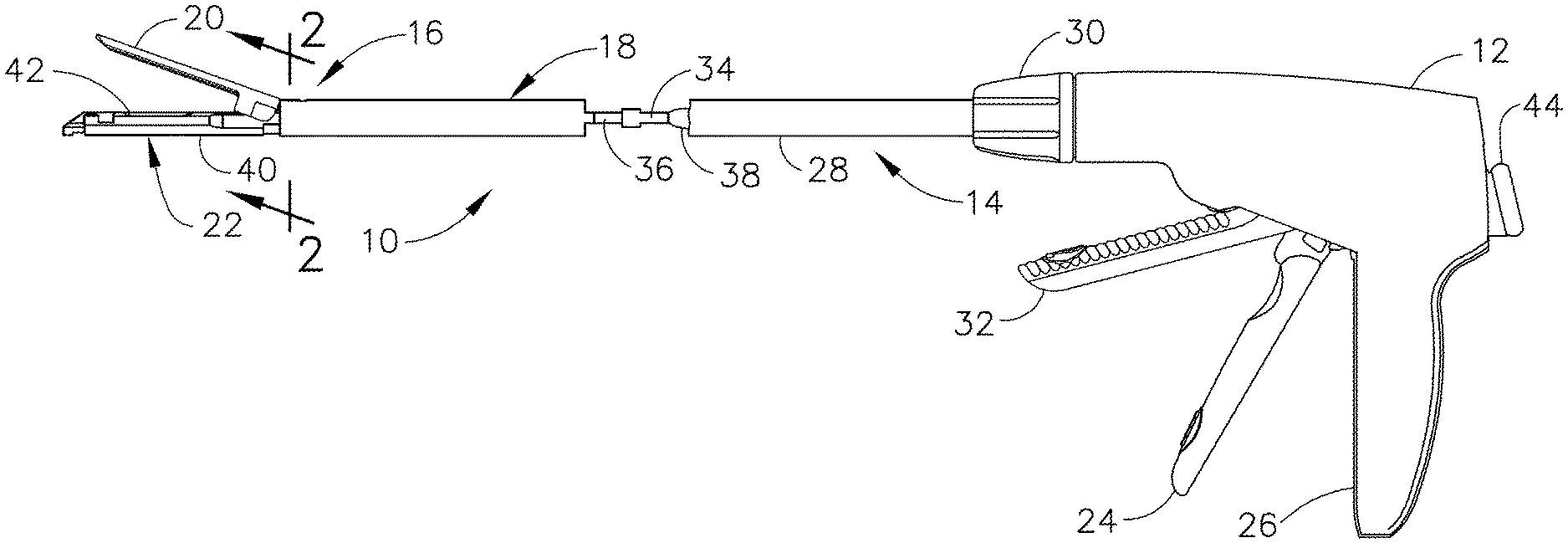
An end effector for use with a surgical instrument includes an anvil with at least one staple pocket that defines a longitudinal axis. The staple pocket comprises a first cup and a second cup. The end effector also includes a staple cartridge.
| Inventors: | Hess; Christopher J. (Blue Ash, OH), Morgan; Jerome R. (Cincinnati, OH), Weisenburgh, II; William B. (Maineville, OH), Voegele; James W. (Cincinnati, OH), Ortiz; Mark S. (Milford, OH), Stokes; Michael J. (Cincinnati, OH), Shurtleff; Carl J. (Mason, OH), Shelton, IV; Frederick E. (Hillsboro, OH), Swayze; Jeffrey S. (West Chester, OH), Bedi; James J. (Cincinnati, OH), Dunki-Jacobs; Adam R. (Cincinnati, OH) | ||||||||||
|---|---|---|---|---|---|---|---|---|---|---|---|
| Applicant: |
|
||||||||||
| Assignee: | Ethicon LLC (Guaynabo,
PR) |
||||||||||
| Family ID: | 55583277 | ||||||||||
| Appl. No.: | 14/963,546 | ||||||||||
| Filed: | December 9, 2015 |
Prior Publication Data
| Document Identifier | Publication Date | |
|---|---|---|
| US 20160089137 A1 | Mar 31, 2016 | |
Related U.S. Patent Documents
| Application Number | Filing Date | Patent Number | Issue Date | ||
|---|---|---|---|---|---|
| 13776803 | Feb 26, 2013 | ||||
| 12880414 | Sep 13, 2010 | ||||
| 12622130 | Nov 19, 2009 | ||||
| 11541123 | Sep 29, 2006 | 7794475 | |||
| 61250377 | Oct 9, 2009 | ||||
| Current U.S. Class: | 1/1 |
| Current CPC Class: | A61B 17/07292 (20130101); A61B 17/0644 (20130101); B21D 53/46 (20130101); A61B 17/1155 (20130101); F16B 15/00 (20130101); A61B 17/07207 (20130101); A61B 17/115 (20130101); A61B 17/0682 (20130101); A61B 2017/07228 (20130101); A61B 2090/0811 (20160201); A61B 2018/00666 (20130101); A61B 2017/00128 (20130101); A61B 2017/320052 (20130101); A61B 17/34 (20130101); A61B 90/03 (20160201); A61B 2017/00831 (20130101); A61B 2090/0801 (20160201); A61B 2017/00004 (20130101); A61B 2017/07264 (20130101); A61B 2017/07285 (20130101); A61B 2017/00539 (20130101); A61B 2090/032 (20160201); A61B 17/1114 (20130101); A61B 2017/00862 (20130101); A61B 2017/2932 (20130101); A61B 2017/2943 (20130101); A61B 2017/07242 (20130101); A61B 2017/0725 (20130101); A61B 2017/07271 (20130101); A61B 2090/036 (20160201); A61B 2090/065 (20160201); A61B 17/105 (20130101); A61B 2017/0641 (20130101); A61B 2017/07278 (20130101) |
| Current International Class: | A61B 17/064 (20060101); B21D 53/46 (20060101); A61B 17/115 (20060101); A61B 17/072 (20060101); A61B 17/068 (20060101); F16B 15/00 (20060101); A61B 17/10 (20060101); A61B 17/11 (20060101); A61B 17/00 (20060101); A61B 17/34 (20060101); A61B 17/29 (20060101); A61B 17/32 (20060101); A61B 18/00 (20060101); A61B 90/00 (20160101) |
| Field of Search: | ;59/77 |
References Cited [Referenced By]
U.S. Patent Documents
| 66052 | June 1867 | Smith |
| 662587 | November 1900 | Blake |
| 670748 | March 1901 | Weddeler |
| 951393 | March 1910 | Hahn |
| 1306107 | June 1919 | Elliott |
| 1314601 | September 1919 | McCaskey |
| 1677337 | July 1928 | Grove |
| 1794907 | March 1931 | Kelly |
| 2037727 | April 1936 | La Chapelle |
| 2132295 | October 1938 | Hawkins |
| 2161632 | June 1939 | Nattenheimer |
| 2211117 | August 1940 | Hess |
| 2214870 | September 1940 | West |
| 2318379 | May 1943 | Davis et al. |
| 2441096 | May 1948 | Happe |
| 2526902 | October 1950 | Rublee |
| 2578686 | December 1951 | Fish |
| 2674149 | April 1954 | Benson |
| 2711461 | June 1955 | Happe |
| 2804848 | September 1957 | O'Farrell et al. |
| 2808482 | October 1957 | Zanichkowsky et al. |
| 2853074 | September 1958 | Olson |
| 2959974 | November 1960 | Emrick |
| 3032769 | May 1962 | Palmer |
| 3075062 | January 1963 | Iaccarino |
| 3078465 | February 1963 | Bobrov |
| 3079606 | March 1963 | Bobrov et al. |
| 3166072 | January 1965 | Sullivan, Jr. |
| 3196869 | July 1965 | Scholl |
| 3266494 | August 1966 | Brownrigg et al. |
| 3269630 | August 1966 | Fleischer |
| 3275211 | September 1966 | Hirsch et al. |
| 3317103 | May 1967 | Cullen et al. |
| 3317105 | May 1967 | Astafjev et al. |
| 3357296 | December 1967 | Lefever |
| 3490675 | January 1970 | Green et al. |
| 3494533 | February 1970 | Green et al. |
| 3499591 | March 1970 | Green |
| 3503396 | March 1970 | Pierie et al. |
| 3551987 | January 1971 | Wilkinson |
| 3568675 | March 1971 | Harvey |
| 3572159 | March 1971 | Tschanz |
| 3598943 | August 1971 | Barrett |
| 3608549 | September 1971 | Merrill |
| 3640317 | February 1972 | Panfili |
| 3643851 | February 1972 | Green et al. |
| 3661666 | May 1972 | Foster et al. |
| 3662939 | May 1972 | Bryan |
| 3695646 | October 1972 | Mommsen |
| 3709221 | January 1973 | Riely |
| 3717294 | February 1973 | Green |
| 3734207 | May 1973 | Fishbein |
| 3740994 | June 1973 | De Carlo, Jr. |
| 3744495 | July 1973 | Johnson |
| 3746002 | July 1973 | Haller |
| 3751902 | August 1973 | Kingsbury et al. |
| 3819100 | June 1974 | Noiles et al. |
| 3821919 | July 1974 | Knohl |
| 3841474 | October 1974 | Maier |
| 3851196 | November 1974 | Hinds |
| 3885491 | May 1975 | Curtis |
| 3892228 | July 1975 | Mitsui |
| 3894174 | July 1975 | Cartun |
| 3940844 | March 1976 | Colby et al. |
| 3955581 | May 1976 | Spasiano et al. |
| RE28932 | August 1976 | Noiles et al. |
| 3981051 | September 1976 | Brumlik |
| 4054108 | October 1977 | Gill |
| 4060089 | November 1977 | Noiles |
| 4106446 | August 1978 | Yamada et al. |
| 4111206 | September 1978 | Vishnevsky et al. |
| 4129059 | December 1978 | Van Eck |
| 4169990 | October 1979 | Lerdman |
| 4180285 | December 1979 | Reneau |
| 4198734 | April 1980 | Brumlik |
| 4198982 | April 1980 | Fortner et al. |
| 4207898 | June 1980 | Becht |
| 4213562 | July 1980 | Garrett et al. |
| 4226242 | October 1980 | Jarvik |
| 4244372 | January 1981 | Kapitanov et al. |
| 4250436 | February 1981 | Weissman |
| 4261244 | April 1981 | Becht et al. |
| 4272002 | June 1981 | Moshofsky |
| 4272662 | June 1981 | Simpson |
| 4274304 | June 1981 | Curtiss |
| 4275813 | June 1981 | Noiles |
| 4289133 | September 1981 | Rothfuss |
| 4290542 | September 1981 | Fedotov et al. |
| 4296654 | October 1981 | Mercer |
| 4296881 | October 1981 | Lee |
| 4304236 | December 1981 | Conta et al. |
| 4305539 | December 1981 | Korolkov et al. |
| 4312685 | January 1982 | Riedl |
| 4317451 | March 1982 | Cerwin et al. |
| 4321002 | March 1982 | Froehlich |
| 4328839 | May 1982 | Lyons et al. |
| 4331277 | May 1982 | Green |
| 4340331 | July 1982 | Savino |
| 4347450 | August 1982 | Colligan |
| 4349028 | September 1982 | Green |
| 4353371 | October 1982 | Cosman |
| 4379457 | April 1983 | Gravener et al. |
| 4380312 | April 1983 | Landrus |
| 4382326 | May 1983 | Rabuse |
| 4383634 | May 1983 | Green |
| 4393728 | July 1983 | Larson et al. |
| 4396139 | August 1983 | Hall et al. |
| 4397311 | August 1983 | Kanshin et al. |
| 4402445 | September 1983 | Green |
| 4408692 | October 1983 | Sigel et al. |
| 4409057 | October 1983 | Molenda et al. |
| 4415112 | November 1983 | Green |
| 4416276 | November 1983 | Newton et al. |
| 4428376 | January 1984 | Mericle |
| 4429695 | February 1984 | Green |
| 4434796 | March 1984 | Karapetian et al. |
| 4438659 | March 1984 | Desplats |
| 4442964 | April 1984 | Becht |
| 4448194 | May 1984 | DiGiovanni et al. |
| 4451743 | May 1984 | Suzuki et al. |
| 4454887 | June 1984 | Kruger |
| 4467805 | August 1984 | Fukuda |
| 4473077 | September 1984 | Noiles et al. |
| 4475679 | October 1984 | Fleury, Jr. |
| 4485816 | December 1984 | Krumme |
| 4486928 | December 1984 | Tucker et al. |
| 4488523 | December 1984 | Shichman |
| 4489875 | December 1984 | Crawford et al. |
| 4499895 | February 1985 | Takayama |
| 4500024 | February 1985 | DiGiovanni et al. |
| 4505272 | March 1985 | Utyamyshev et al. |
| 4505273 | March 1985 | Braun et al. |
| 4505414 | March 1985 | Filipi |
| 4506671 | March 1985 | Green |
| 4520817 | June 1985 | Green |
| 4522327 | June 1985 | Korthoff et al. |
| 4526174 | July 1985 | Froehlich |
| 4527724 | July 1985 | Chow et al. |
| 4530453 | July 1985 | Green |
| 4531522 | July 1985 | Bedi et al. |
| 4532927 | August 1985 | Miksza, Jr. |
| 4548202 | October 1985 | Duncan |
| 4565109 | January 1986 | Tsay |
| 4565189 | January 1986 | Mabuchi |
| 4566620 | January 1986 | Green et al. |
| 4569469 | February 1986 | Mongeon et al. |
| 4571213 | February 1986 | Ishimoto |
| 4573468 | March 1986 | Conta et al. |
| 4573469 | March 1986 | Golden et al. |
| 4573622 | March 1986 | Green et al. |
| 4576167 | March 1986 | Noiles |
| 4580712 | April 1986 | Green |
| 4585153 | April 1986 | Failla et al. |
| 4589416 | May 1986 | Green |
| 4591085 | May 1986 | Di Giovanni |
| 4597753 | July 1986 | Turley |
| 4600037 | July 1986 | Hatten |
| 4604786 | August 1986 | Howie, Jr. |
| 4605001 | August 1986 | Rothfuss et al. |
| 4605004 | August 1986 | Di Giovanni et al. |
| 4606343 | August 1986 | Conta et al. |
| 4607638 | August 1986 | Crainich |
| 4608981 | September 1986 | Rothfuss et al. |
| 4610250 | September 1986 | Green |
| 4610383 | September 1986 | Rothfuss et al. |
| 4619262 | October 1986 | Taylor |
| 4619391 | October 1986 | Sharkany et al. |
| 4628459 | December 1986 | Shinohara et al. |
| 4629107 | December 1986 | Fedotov et al. |
| 4632290 | December 1986 | Green et al. |
| 4633874 | January 1987 | Chow et al. |
| 4634419 | January 1987 | Kreizman et al. |
| 4641076 | February 1987 | Linden |
| 4643731 | February 1987 | Eckenhoff |
| 4646722 | March 1987 | Silverstein et al. |
| 4655222 | April 1987 | Florez |
| 4662555 | May 1987 | Thornton |
| 4663874 | May 1987 | Sano et al. |
| 4664305 | May 1987 | Blake, III et al. |
| 4665916 | May 1987 | Green |
| 4667674 | May 1987 | Korthoff et al. |
| 4669647 | June 1987 | Storace |
| 4671445 | June 1987 | Barker et al. |
| 4676245 | June 1987 | Fukuda |
| 4684051 | August 1987 | Akopov et al. |
| 4693248 | September 1987 | Failla |
| 4700703 | October 1987 | Resnick et al. |
| 4708141 | November 1987 | Inoue et al. |
| 4709120 | November 1987 | Pearson |
| 4715520 | December 1987 | Roehr, Jr. et al. |
| 4719917 | January 1988 | Barrows et al. |
| 4727308 | February 1988 | Huljak et al. |
| 4728020 | March 1988 | Green et al. |
| 4728876 | March 1988 | Mongeon et al. |
| 4729260 | March 1988 | Dudden |
| 4730726 | March 1988 | Holzwarth |
| 4741336 | May 1988 | Failla et al. |
| 4743214 | May 1988 | Tai-Cheng |
| 4747820 | May 1988 | Hornlein et al. |
| 4750902 | June 1988 | Wuchinich et al. |
| 4752024 | June 1988 | Green et al. |
| 4754909 | July 1988 | Barker et al. |
| 4767044 | August 1988 | Green |
| 4773420 | September 1988 | Green |
| 4777780 | October 1988 | Holzwarth |
| 4787387 | November 1988 | Burbank, III et al. |
| 4790225 | December 1988 | Moody et al. |
| 4805617 | February 1989 | Bedi et al. |
| 4805823 | February 1989 | Rothfuss |
| 4809695 | March 1989 | Gwathmey et al. |
| 4815460 | March 1989 | Porat et al. |
| 4817847 | April 1989 | Redtenbacher et al. |
| 4819853 | April 1989 | Green |
| 4821939 | April 1989 | Green |
| 4827911 | May 1989 | Broadwin et al. |
| 4830855 | May 1989 | Stewart |
| 4834720 | May 1989 | Blinkhorn |
| 4844068 | July 1989 | Arata et al. |
| 4848637 | July 1989 | Pruitt |
| 4865030 | September 1989 | Polyak |
| 4869414 | September 1989 | Green et al. |
| 4869415 | September 1989 | Fox |
| 4873977 | October 1989 | Avant et al. |
| 4880015 | November 1989 | Nierman |
| 4890613 | January 1990 | Golden et al. |
| 4892244 | January 1990 | Fox et al. |
| 4893622 | January 1990 | Green et al. |
| 4896678 | January 1990 | Ogawa |
| 4900303 | February 1990 | Lemelson |
| 4903697 | February 1990 | Resnick et al. |
| 4915100 | April 1990 | Green |
| 4930503 | June 1990 | Pruitt |
| 4930674 | June 1990 | Barak |
| 4931047 | June 1990 | Broadwin et al. |
| 4932960 | June 1990 | Green et al. |
| 4938408 | July 1990 | Bedi et al. |
| 4941623 | July 1990 | Pruitt |
| 4944443 | July 1990 | Oddsen et al. |
| 4955959 | September 1990 | Tompkins et al. |
| 4965709 | October 1990 | Ngo |
| 4973274 | November 1990 | Hirukawa |
| 4978049 | December 1990 | Green |
| 4978333 | December 1990 | Broadwin et al. |
| 4986808 | January 1991 | Broadwin et al. |
| 4988334 | January 1991 | Hornlein et al. |
| 5002543 | March 1991 | Bradshaw et al. |
| 5002553 | March 1991 | Shiber |
| 5005754 | April 1991 | Van Overloop |
| 5009661 | April 1991 | Michelson |
| 5014899 | May 1991 | Presty et al. |
| 5015227 | May 1991 | Broadwin et al. |
| 5018515 | May 1991 | Gilman |
| 5018657 | May 1991 | Pedlick et al. |
| 5024671 | June 1991 | Tu et al. |
| 5027834 | July 1991 | Pruitt |
| 5031814 | July 1991 | Tompkins et al. |
| 5035040 | July 1991 | Kerrigan et al. |
| 5038109 | August 1991 | Goble et al. |
| 5040715 | August 1991 | Green et al. |
| 5042707 | August 1991 | Taheri |
| 5061269 | October 1991 | Muller |
| 5062563 | November 1991 | Green et al. |
| 5065929 | November 1991 | Schulze et al. |
| 5071052 | December 1991 | Rodak et al. |
| 5071430 | December 1991 | de Salis et al. |
| 5074454 | December 1991 | Peters |
| 5079006 | January 1992 | Urquhart |
| 5080556 | January 1992 | Carreno |
| 5083695 | January 1992 | Foslien et al. |
| 5084057 | January 1992 | Green et al. |
| 5088979 | February 1992 | Filipi et al. |
| 5088997 | February 1992 | Delahuerga et al. |
| 5094247 | March 1992 | Hernandez et al. |
| 5100420 | March 1992 | Green et al. |
| 5104025 | April 1992 | Main et al. |
| 5104397 | April 1992 | Vasconcelos et al. |
| 5106008 | April 1992 | Tompkins et al. |
| 5108368 | April 1992 | Hammerslag et al. |
| 5111987 | May 1992 | Moeinzadeh et al. |
| 5116349 | May 1992 | Aranyi |
| 5122156 | June 1992 | Granger et al. |
| 5129570 | July 1992 | Schulze et al. |
| 5137198 | August 1992 | Nobis et al. |
| 5139513 | August 1992 | Segato |
| 5141144 | August 1992 | Foslien et al. |
| 5142932 | September 1992 | Moya et al. |
| 5155941 | October 1992 | Takahashi et al. |
| 5156315 | October 1992 | Green et al. |
| 5156609 | October 1992 | Nakao et al. |
| 5156614 | October 1992 | Green et al. |
| 5158567 | October 1992 | Green |
| D330699 | November 1992 | Gill |
| 5163598 | November 1992 | Peters et al. |
| 5171247 | December 1992 | Hughett et al. |
| 5171249 | December 1992 | Stefanchik et al. |
| 5171253 | December 1992 | Klieman |
| 5173133 | December 1992 | Morin et al. |
| 5188111 | February 1993 | Yates et al. |
| 5190517 | March 1993 | Zieve et al. |
| 5190544 | March 1993 | Chapman et al. |
| 5192288 | March 1993 | Thompson et al. |
| 5195968 | March 1993 | Lundquist et al. |
| 5197648 | March 1993 | Gingold |
| 5197649 | March 1993 | Bessler et al. |
| 5197966 | March 1993 | Sommerkamp |
| 5200280 | April 1993 | Karasa |
| 5205459 | April 1993 | Brinkerhoff et al. |
| 5207697 | May 1993 | Carusillo et al. |
| 5209747 | May 1993 | Knoepfler |
| 5211649 | May 1993 | Kohler et al. |
| 5211655 | May 1993 | Hasson |
| 5217457 | June 1993 | Delahuerga et al. |
| 5217478 | June 1993 | Rexroth |
| 5219111 | June 1993 | Bilotti et al. |
| 5221036 | June 1993 | Takase |
| 5221281 | June 1993 | Klicek |
| 5222963 | June 1993 | Brinkerhoff et al. |
| 5222975 | June 1993 | Crainich |
| 5222976 | June 1993 | Yoon |
| 5223675 | June 1993 | Taft |
| 5234447 | August 1993 | Kaster et al. |
| 5236424 | August 1993 | Imran |
| 5236440 | August 1993 | Hlavacek |
| 5239981 | August 1993 | Anapliotis |
| 5240163 | August 1993 | Stein et al. |
| 5242457 | September 1993 | Akopov et al. |
| 5244462 | September 1993 | Delahuerga et al. |
| 5246156 | September 1993 | Rothfuss et al. |
| 5246443 | September 1993 | Mai |
| 5253793 | October 1993 | Green et al. |
| 5258009 | November 1993 | Conners |
| 5258012 | November 1993 | Luscombe et al. |
| 5259366 | November 1993 | Reydel et al. |
| 5260637 | November 1993 | Pizzi |
| 5263629 | November 1993 | Trumbull et al. |
| 5263973 | November 1993 | Cook |
| 5264218 | November 1993 | Rogozinski |
| 5268622 | December 1993 | Philipp |
| 5271543 | December 1993 | Grant et al. |
| 5271544 | December 1993 | Fox et al. |
| RE34519 | January 1994 | Fox et al. |
| 5275323 | January 1994 | Schulze et al. |
| 5275608 | January 1994 | Forman et al. |
| 5279416 | January 1994 | Malec et al. |
| 5281216 | January 1994 | Klicek |
| 5282806 | February 1994 | Haber et al. |
| 5282829 | February 1994 | Hermes |
| 5284128 | February 1994 | Hart |
| 5285945 | February 1994 | Brinkerhoff et al. |
| 5289963 | March 1994 | McGarry et al. |
| 5290271 | March 1994 | Jernberg |
| 5292053 | March 1994 | Bilotti et al. |
| 5297714 | March 1994 | Kramer |
| 5304204 | April 1994 | Bregen |
| 5307976 | May 1994 | Olson et al. |
| 5309927 | May 1994 | Welch |
| 5312023 | May 1994 | Green et al. |
| 5312024 | May 1994 | Grant et al. |
| 5312329 | May 1994 | Beaty et al. |
| 5314424 | May 1994 | Nicholas |
| 5314445 | May 1994 | Heidmueller nee Degwitz et al. |
| 5314466 | May 1994 | Stern et al. |
| 5318221 | June 1994 | Green et al. |
| 5330487 | July 1994 | Thornton et al. |
| 5330502 | July 1994 | Hassler et al. |
| 5332142 | July 1994 | Robinson et al. |
| 5333422 | August 1994 | Warren et al. |
| 5333772 | August 1994 | Rothfuss et al. |
| 5333773 | August 1994 | Main et al. |
| 5334183 | August 1994 | Wuchinich |
| 5336232 | August 1994 | Green et al. |
| 5339799 | August 1994 | Kami et al. |
| 5341724 | August 1994 | Vatel |
| 5341810 | August 1994 | Dardel |
| 5342381 | August 1994 | Tidemand |
| 5342395 | August 1994 | Jarrett et al. |
| 5342396 | August 1994 | Cook |
| 5344060 | September 1994 | Gravener et al. |
| 5344454 | September 1994 | Clarke et al. |
| 5346504 | September 1994 | Ortiz et al. |
| 5348259 | September 1994 | Blanco et al. |
| 5350388 | September 1994 | Epstein |
| 5350391 | September 1994 | Iacovelli |
| 5350400 | September 1994 | Esposito et al. |
| 5352229 | October 1994 | Goble et al. |
| 5352235 | October 1994 | Koros et al. |
| 5352238 | October 1994 | Green et al. |
| 5354303 | October 1994 | Spaeth et al. |
| 5356006 | October 1994 | Alpern et al. |
| 5358506 | October 1994 | Green et al. |
| 5358510 | October 1994 | Luscombe et al. |
| 5359231 | October 1994 | Flowers et al. |
| D352780 | November 1994 | Glaeser et al. |
| 5360305 | November 1994 | Kerrigan |
| 5360428 | November 1994 | Hutchinson, Jr. |
| 5364001 | November 1994 | Bryan |
| 5364003 | November 1994 | Williamson, IV |
| 5366133 | November 1994 | Geiste |
| 5366134 | November 1994 | Green et al. |
| 5366479 | November 1994 | McGarry et al. |
| 5368015 | November 1994 | Wilk |
| 5368592 | November 1994 | Stern et al. |
| 5370645 | December 1994 | Klicek et al. |
| 5372124 | December 1994 | Takayama et al. |
| 5372596 | December 1994 | Klicek et al. |
| 5372602 | December 1994 | Burke |
| 5374277 | December 1994 | Hassler |
| 5376095 | December 1994 | Ortiz |
| 5379933 | January 1995 | Green et al. |
| 5381649 | January 1995 | Webb |
| 5381782 | January 1995 | DeLaRama et al. |
| 5382247 | January 1995 | Cimino et al. |
| 5383880 | January 1995 | Hooven |
| 5383881 | January 1995 | Green et al. |
| 5383888 | January 1995 | Zvenyatsky et al. |
| 5383895 | January 1995 | Holmes et al. |
| 5389098 | February 1995 | Tsuruta et al. |
| 5389104 | February 1995 | Hahnen et al. |
| 5391180 | February 1995 | Tovey et al. |
| 5392979 | February 1995 | Green et al. |
| 5395030 | March 1995 | Kuramoto et al. |
| 5395033 | March 1995 | Byrne et al. |
| 5395034 | March 1995 | Allen et al. |
| 5395312 | March 1995 | Desai |
| 5395384 | March 1995 | Duthoit et al. |
| 5397046 | March 1995 | Savage et al. |
| 5397324 | March 1995 | Carroll et al. |
| 5403312 | April 1995 | Yates et al. |
| 5405072 | April 1995 | Zlock et al. |
| 5405073 | April 1995 | Porter |
| 5405344 | April 1995 | Williamson et al. |
| 5405360 | April 1995 | Tovey |
| 5407293 | April 1995 | Crainich |
| 5409498 | April 1995 | Braddock et al. |
| 5411508 | May 1995 | Bessler et al. |
| 5413107 | May 1995 | Oakley et al. |
| 5413267 | May 1995 | Solyntjes et al. |
| 5413268 | May 1995 | Green et al. |
| 5413272 | May 1995 | Green et al. |
| 5413573 | May 1995 | Koivukangas |
| 5415334 | May 1995 | Williamson et al. |
| 5415335 | May 1995 | Knodell, Jr. |
| 5417203 | May 1995 | Tovey et al. |
| 5417361 | May 1995 | Williamson, IV |
| 5421829 | June 1995 | Olichney et al. |
| 5422567 | June 1995 | Matsunaga |
| 5423471 | June 1995 | Mastri et al. |
| 5423809 | June 1995 | Klicek |
| 5425745 | June 1995 | Green et al. |
| 5431322 | July 1995 | Green et al. |
| 5431654 | July 1995 | Nic |
| 5431668 | July 1995 | Burbank, III et al. |
| 5433721 | July 1995 | Hooven et al. |
| 5437681 | August 1995 | Meade et al. |
| 5438302 | August 1995 | Goble |
| 5439155 | August 1995 | Viola |
| 5439156 | August 1995 | Grant et al. |
| 5439479 | August 1995 | Shichman et al. |
| 5441191 | August 1995 | Linden |
| 5441193 | August 1995 | Gravener |
| 5441483 | August 1995 | Avitall |
| 5441494 | August 1995 | Ortiz |
| 5444113 | August 1995 | Sinclair et al. |
| 5445155 | August 1995 | Sieben |
| 5445304 | August 1995 | Plyley et al. |
| 5445644 | August 1995 | Pietrafitta et al. |
| 5447265 | September 1995 | Vidal et al. |
| 5447417 | September 1995 | Kuhl et al. |
| 5447513 | September 1995 | Davison et al. |
| 5449355 | September 1995 | Rhum et al. |
| 5449365 | September 1995 | Green et al. |
| 5449370 | September 1995 | Vaitekunas |
| 5452836 | September 1995 | Huitema et al. |
| 5452837 | September 1995 | Williamson, IV et al. |
| 5454378 | October 1995 | Palmer et al. |
| 5454827 | October 1995 | Aust et al. |
| 5456401 | October 1995 | Green et al. |
| 5458579 | October 1995 | Chodorow et al. |
| 5462215 | October 1995 | Viola et al. |
| 5464013 | November 1995 | Lemelson |
| 5464144 | November 1995 | Guy et al. |
| 5464300 | November 1995 | Crainich |
| 5465894 | November 1995 | Clark et al. |
| 5465895 | November 1995 | Knodel et al. |
| 5465896 | November 1995 | Allen et al. |
| 5466020 | November 1995 | Page et al. |
| 5467911 | November 1995 | Tsuruta et al. |
| 5468253 | November 1995 | Bezwada et al. |
| 5470006 | November 1995 | Rodak |
| 5470007 | November 1995 | Plyley et al. |
| 5470009 | November 1995 | Rodak |
| 5470010 | November 1995 | Rothfuss et al. |
| 5472132 | December 1995 | Savage et al. |
| 5472442 | December 1995 | Klicek |
| 5473204 | December 1995 | Temple |
| 5474057 | December 1995 | Makower et al. |
| 5474223 | December 1995 | Viola et al. |
| 5474566 | December 1995 | Alesi et al. |
| 5476206 | December 1995 | Green et al. |
| 5476479 | December 1995 | Green et al. |
| 5478003 | December 1995 | Green et al. |
| 5478354 | December 1995 | Tovey et al. |
| 5480089 | January 1996 | Blewett |
| 5480409 | January 1996 | Riza |
| 5482197 | January 1996 | Green et al. |
| 5484095 | January 1996 | Green et al. |
| 5484398 | January 1996 | Stoddard |
| 5484451 | January 1996 | Akopov et al. |
| 5485947 | January 1996 | Olson et al. |
| 5485952 | January 1996 | Fontayne |
| 5487499 | January 1996 | Sorrentino et al. |
| 5487500 | January 1996 | Knodel et al. |
| 5489058 | February 1996 | Plyley et al. |
| 5489256 | February 1996 | Adair |
| 5496312 | March 1996 | Klicek |
| 5496317 | March 1996 | Goble et al. |
| 5497933 | March 1996 | DeFonzo et al. |
| 5501654 | March 1996 | Failla et al. |
| 5503320 | April 1996 | Webster et al. |
| 5503635 | April 1996 | Sauer et al. |
| 5503638 | April 1996 | Cooper et al. |
| 5505363 | April 1996 | Green et al. |
| 5507426 | April 1996 | Young et al. |
| 5509596 | April 1996 | Green et al. |
| 5509916 | April 1996 | Taylor |
| 5511564 | April 1996 | Wilk |
| 5514129 | May 1996 | Smith |
| 5514157 | May 1996 | Nicholas et al. |
| 5518163 | May 1996 | Hooven |
| 5518164 | May 1996 | Hooven |
| 5520678 | May 1996 | Heckele et al. |
| 5520700 | May 1996 | Beyar et al. |
| 5522817 | June 1996 | Sander et al. |
| 5527320 | June 1996 | Carruthers et al. |
| 5529235 | June 1996 | Boiarski et al. |
| D372086 | July 1996 | Grasso et al. |
| 5531305 | July 1996 | Roberts et al. |
| 5531744 | July 1996 | Nardella et al. |
| 5533521 | July 1996 | Granger |
| 5533581 | July 1996 | Barth et al. |
| 5533661 | July 1996 | Main et al. |
| 5535934 | July 1996 | Boiarski et al. |
| 5535935 | July 1996 | Vidal et al. |
| 5535937 | July 1996 | Boiarski et al. |
| 5540375 | July 1996 | Bolanos et al. |
| 5541376 | July 1996 | Ladtkow et al. |
| 5542594 | August 1996 | McKean et al. |
| 5542949 | August 1996 | Yoon |
| 5543119 | August 1996 | Sutter et al. |
| 5547117 | August 1996 | Hamblin et al. |
| 5549621 | August 1996 | Bessler et al. |
| 5549627 | August 1996 | Kieturakis |
| 5549628 | August 1996 | Cooper et al. |
| 5549637 | August 1996 | Crainich |
| 5551622 | September 1996 | Yoon |
| 5553675 | September 1996 | Pitzen et al. |
| 5553765 | September 1996 | Knodel et al. |
| 5554148 | September 1996 | Aebischer et al. |
| 5554169 | September 1996 | Green et al. |
| 5556416 | September 1996 | Clark et al. |
| 5558665 | September 1996 | Kieturakis |
| 5558671 | September 1996 | Yates |
| 5560530 | October 1996 | Bolanos et al. |
| 5560532 | October 1996 | DeFonzo et al. |
| 5562239 | October 1996 | Boiarski et al. |
| 5562241 | October 1996 | Knodel et al. |
| 5562682 | October 1996 | Oberlin et al. |
| 5562690 | October 1996 | Green et al. |
| 5562701 | October 1996 | Huitema et al. |
| 5562702 | October 1996 | Huitema et al. |
| 5564615 | October 1996 | Bishop et al. |
| 5569161 | October 1996 | Ebling et al. |
| 5569270 | October 1996 | Weng |
| 5569284 | October 1996 | Young et al. |
| 5571090 | November 1996 | Sherts |
| 5571100 | November 1996 | Goble et al. |
| 5571116 | November 1996 | Bolanos et al. |
| 5571285 | November 1996 | Chow et al. |
| 5573543 | November 1996 | Akopov et al. |
| 5574431 | November 1996 | McKeown et al. |
| 5575054 | November 1996 | Klinzing et al. |
| 5575789 | November 1996 | Bell et al. |
| 5575799 | November 1996 | Bolanos et al. |
| 5575803 | November 1996 | Cooper et al. |
| 5575805 | November 1996 | Li |
| 5577654 | November 1996 | Bishop |
| 5579978 | December 1996 | Green et al. |
| 5580067 | December 1996 | Hamblin et al. |
| 5582611 | December 1996 | Tsuruta et al. |
| 5582617 | December 1996 | Klieman et al. |
| 5584425 | December 1996 | Savage et al. |
| 5586711 | December 1996 | Plyley et al. |
| 5588579 | December 1996 | Schnut et al. |
| 5588580 | December 1996 | Paul et al. |
| 5588581 | December 1996 | Conlon et al. |
| 5591170 | January 1997 | Spievack et al. |
| 5591187 | January 1997 | Dekel |
| 5597107 | January 1997 | Knodel et al. |
| 5599151 | February 1997 | Daum et al. |
| 5599279 | February 1997 | Slotman et al. |
| 5599344 | February 1997 | Paterson |
| 5599350 | February 1997 | Schulze et al. |
| 5599852 | February 1997 | Scopelianos et al. |
| 5601224 | February 1997 | Bishop et al. |
| 5603443 | February 1997 | Clark et al. |
| 5605272 | February 1997 | Witt et al. |
| 5605273 | February 1997 | Hamblin et al. |
| 5607094 | March 1997 | Clark et al. |
| 5607095 | March 1997 | Smith et al. |
| 5607433 | March 1997 | Polla et al. |
| 5607450 | March 1997 | Zvenyatsky et al. |
| 5609285 | March 1997 | Grant et al. |
| 5609601 | March 1997 | Kolesa et al. |
| 5611709 | March 1997 | McAnulty |
| 5613966 | March 1997 | Makower et al. |
| 5615820 | April 1997 | Viola |
| 5618294 | April 1997 | Aust et al. |
| 5618303 | April 1997 | Marlow et al. |
| 5618307 | April 1997 | Donlon et al. |
| 5619992 | April 1997 | Guthrie et al. |
| 5620289 | April 1997 | Curry |
| 5620452 | April 1997 | Yoon |
| 5624398 | April 1997 | Smith et al. |
| 5624452 | April 1997 | Yates |
| 5626587 | May 1997 | Bishop et al. |
| 5626595 | May 1997 | Sklar et al. |
| 5628446 | May 1997 | Geiste et al. |
| 5628743 | May 1997 | Cimino |
| 5628745 | May 1997 | Bek |
| 5630539 | May 1997 | Plyley et al. |
| 5630540 | May 1997 | Blewett |
| 5630541 | May 1997 | Williamson, IV et al. |
| 5630782 | May 1997 | Adair |
| 5632432 | May 1997 | Schulze et al. |
| 5632433 | May 1997 | Grant et al. |
| 5634584 | June 1997 | Okorocha et al. |
| 5636779 | June 1997 | Palmer |
| 5636780 | June 1997 | Green et al. |
| 5639008 | June 1997 | Gallagher et al. |
| 5643291 | July 1997 | Pier et al. |
| 5645209 | July 1997 | Green et al. |
| 5647526 | July 1997 | Green et al. |
| 5647869 | July 1997 | Goble et al. |
| 5649937 | July 1997 | Bito et al. |
| 5649956 | July 1997 | Jensen et al. |
| 5651491 | July 1997 | Heaton et al. |
| 5653373 | August 1997 | Green et al. |
| 5653374 | August 1997 | Young et al. |
| 5653677 | August 1997 | Okada et al. |
| 5653721 | August 1997 | Knodel et al. |
| 5655698 | August 1997 | Yoon |
| 5657921 | August 1997 | Young et al. |
| 5658281 | August 1997 | Heard |
| 5658300 | August 1997 | Bito et al. |
| 5658307 | August 1997 | Exconde |
| 5662258 | September 1997 | Knodel et al. |
| 5662260 | September 1997 | Yoon |
| 5662662 | September 1997 | Bishop et al. |
| 5665085 | September 1997 | Nardella |
| 5667517 | September 1997 | Hooven |
| 5667526 | September 1997 | Levin |
| 5667527 | September 1997 | Cook |
| 5669544 | September 1997 | Schulze et al. |
| 5669904 | September 1997 | Platt, Jr. et al. |
| 5669907 | September 1997 | Platt, Jr. et al. |
| 5669918 | September 1997 | Balazs et al. |
| 5673840 | October 1997 | Schulze et al. |
| 5673841 | October 1997 | Schulze et al. |
| 5673842 | October 1997 | Bittner et al. |
| 5674286 | October 1997 | D'Alessio et al. |
| 5678748 | October 1997 | Plyley et al. |
| 5680981 | October 1997 | Mililli et al. |
| 5680982 | October 1997 | Schulze et al. |
| 5680983 | October 1997 | Plyley et al. |
| 5683349 | November 1997 | Makower et al. |
| 5685474 | November 1997 | Seeber |
| 5686090 | November 1997 | Schilder et al. |
| 5688270 | November 1997 | Yates et al. |
| 5690269 | November 1997 | Bolanos et al. |
| 5692668 | December 1997 | Schulze et al. |
| 5693020 | December 1997 | Rauh |
| 5693042 | December 1997 | Boiarski et al. |
| 5693051 | December 1997 | Schulze et al. |
| 5695494 | December 1997 | Becker |
| 5695502 | December 1997 | Pier et al. |
| 5695504 | December 1997 | Gifford, III et al. |
| 5695524 | December 1997 | Kelley et al. |
| 5697542 | December 1997 | Knodel et al. |
| 5697543 | December 1997 | Burdorff |
| 5697943 | December 1997 | Sauer et al. |
| 5700270 | December 1997 | Peyser et al. |
| 5702387 | December 1997 | Arts et al. |
| 5702408 | December 1997 | Wales et al. |
| 5702409 | December 1997 | Rayburn et al. |
| 5704087 | January 1998 | Strub |
| 5704534 | January 1998 | Huitema et al. |
| 5706997 | January 1998 | Green et al. |
| 5706998 | January 1998 | Plyley et al. |
| 5707392 | January 1998 | Kortenbach |
| 5709334 | January 1998 | Sorrentino et al. |
| 5709680 | January 1998 | Yates et al. |
| 5709706 | January 1998 | Kienzle et al. |
| 5711472 | January 1998 | Bryan |
| 5713128 | February 1998 | Schrenk et al. |
| 5713505 | February 1998 | Huitema |
| 5713895 | February 1998 | Lontine et al. |
| 5713896 | February 1998 | Nardella |
| 5713920 | February 1998 | Bezwada et al. |
| 5715987 | February 1998 | Kelley et al. |
| 5715988 | February 1998 | Palmer |
| 5716366 | February 1998 | Yates |
| 5718359 | February 1998 | Palmer et al. |
| 5718360 | February 1998 | Green et al. |
| 5718548 | February 1998 | Cotellessa |
| 5720744 | February 1998 | Eggleston et al. |
| D393067 | March 1998 | Geary et al. |
| 5725536 | March 1998 | Oberlin et al. |
| 5725554 | March 1998 | Simon et al. |
| 5728110 | March 1998 | Vidal et al. |
| 5728121 | March 1998 | Bimbo et al. |
| 5730758 | March 1998 | Allgeyer |
| 5732821 | March 1998 | Stone et al. |
| 5732871 | March 1998 | Clark et al. |
| 5732872 | March 1998 | Bolduc et al. |
| 5733308 | March 1998 | Daugherty et al. |
| 5735445 | April 1998 | Vidal et al. |
| 5735848 | April 1998 | Yates et al. |
| 5735874 | April 1998 | Measamer et al. |
| 5738474 | April 1998 | Blewett |
| 5738648 | April 1998 | Lands et al. |
| 5743456 | April 1998 | Jones et al. |
| 5747953 | May 1998 | Philipp |
| 5749889 | May 1998 | Bacich et al. |
| 5749893 | May 1998 | Vidal et al. |
| 5752644 | May 1998 | Bolanos et al. |
| 5752965 | May 1998 | Francis et al. |
| 5755717 | May 1998 | Yates et al. |
| 5758814 | June 1998 | Gallagher et al. |
| 5762255 | June 1998 | Chrisman et al. |
| 5762256 | June 1998 | Mastri et al. |
| 5766188 | June 1998 | Igaki |
| 5766205 | June 1998 | Zvenyatsky et al. |
| 5769892 | June 1998 | Kingwell |
| 5772379 | June 1998 | Evensen |
| 5772578 | June 1998 | Heimberger et al. |
| 5772659 | June 1998 | Becker et al. |
| 5776130 | July 1998 | Buysse et al. |
| 5778939 | July 1998 | Hok-Yin |
| 5779130 | July 1998 | Alesi et al. |
| 5779131 | July 1998 | Knodel et al. |
| 5779132 | July 1998 | Knodel et al. |
| 5782396 | July 1998 | Mastri et al. |
| 5782397 | July 1998 | Koukline |
| 5782749 | July 1998 | Riza |
| 5782859 | July 1998 | Nicholas et al. |
| 5784934 | July 1998 | Izumisawa |
| 5785232 | July 1998 | Vidal et al. |
| 5785647 | July 1998 | Tompkins et al. |
| 5787897 | August 1998 | Kieturakis |
| 5792135 | August 1998 | Madhani et al. |
| 5792165 | August 1998 | Klieman et al. |
| 5794834 | August 1998 | Hamblin et al. |
| 5796188 | August 1998 | Bays |
| 5797536 | August 1998 | Smith et al. |
| 5797537 | August 1998 | Oberlin et al. |
| 5797538 | August 1998 | Heaton et al. |
| 5797906 | August 1998 | Rhum et al. |
| 5797959 | August 1998 | Castro et al. |
| 5799857 | September 1998 | Robertson et al. |
| 5800379 | September 1998 | Edwards |
| 5800423 | September 1998 | Jensen |
| 5806676 | September 1998 | Wasgien |
| 5807376 | September 1998 | Viola et al. |
| 5807378 | September 1998 | Jensen et al. |
| 5807393 | September 1998 | Williamson, IV et al. |
| 5809441 | September 1998 | McKee |
| 5810721 | September 1998 | Mueller et al. |
| 5810811 | September 1998 | Yates et al. |
| 5810846 | September 1998 | Virnich et al. |
| 5810855 | September 1998 | Rayburn et al. |
| 5813813 | September 1998 | Daum et al. |
| 5814055 | September 1998 | Knodel et al. |
| 5814057 | September 1998 | Oi et al. |
| 5816471 | October 1998 | Plyley et al. |
| 5817084 | October 1998 | Jensen |
| 5817091 | October 1998 | Nardella et al. |
| 5817093 | October 1998 | Williamson, IV et al. |
| 5817109 | October 1998 | McGarry et al. |
| 5817119 | October 1998 | Klieman et al. |
| 5820009 | October 1998 | Melling et al. |
| 5823066 | October 1998 | Huitema et al. |
| 5826776 | October 1998 | Schulze et al. |
| 5827271 | October 1998 | Buysse et al. |
| 5827298 | October 1998 | Hart et al. |
| 5829662 | November 1998 | Allen et al. |
| 5833690 | November 1998 | Yates et al. |
| 5833695 | November 1998 | Yoon |
| 5833696 | November 1998 | Whitfield et al. |
| 5836503 | November 1998 | Ehrenfels et al. |
| 5836960 | November 1998 | Kolesa et al. |
| 5839639 | November 1998 | Sauer et al. |
| 5843021 | December 1998 | Edwards et al. |
| 5843096 | December 1998 | Igaki et al. |
| 5843122 | December 1998 | Riza |
| 5843132 | December 1998 | Ilvento |
| 5843169 | December 1998 | Taheri |
| 5846254 | December 1998 | Schulze et al. |
| 5849011 | December 1998 | Jones et al. |
| 5849023 | December 1998 | Mericle |
| 5855311 | January 1999 | Hamblin et al. |
| 5855583 | January 1999 | Wang et al. |
| 5860581 | January 1999 | Robertson et al. |
| 5860975 | January 1999 | Goble et al. |
| 5865361 | February 1999 | Milliman |
| 5868760 | February 1999 | McGuckin, Jr. |
| 5871135 | February 1999 | Williamson, IV et al. |
| 5873885 | February 1999 | Weidenbenner |
| 5876401 | March 1999 | Schulze et al. |
| 5878193 | March 1999 | Wang et al. |
| 5878937 | March 1999 | Green et al. |
| 5878938 | March 1999 | Bittner et al. |
| 5891160 | April 1999 | Williamson, IV et al. |
| 5893506 | April 1999 | Powell |
| 5893835 | April 1999 | Witt et al. |
| 5893878 | April 1999 | Pierce |
| 5894979 | April 1999 | Powell |
| 5897552 | April 1999 | Edwards et al. |
| 5897562 | April 1999 | Bolanos et al. |
| 5899914 | May 1999 | Zirps et al. |
| 5901895 | May 1999 | Heaton et al. |
| 5902312 | May 1999 | Frater et al. |
| 5904647 | May 1999 | Ouchi |
| 5904693 | May 1999 | Dicesare et al. |
| 5906625 | May 1999 | Bito et al. |
| 5908402 | June 1999 | Blythe |
| 5908427 | June 1999 | McKean et al. |
| 5911353 | June 1999 | Bolanos et al. |
| 5915616 | June 1999 | Viola et al. |
| 5916225 | June 1999 | Kugel |
| 5918791 | July 1999 | Sorrentino et al. |
| 5919198 | July 1999 | Graves, Jr. et al. |
| 5921956 | July 1999 | Grinberg et al. |
| 5928256 | July 1999 | Riza |
| 5931847 | August 1999 | Bittner et al. |
| 5931853 | August 1999 | McEwen et al. |
| 5937951 | August 1999 | Izuchukwu et al. |
| 5938667 | August 1999 | Peyser et al. |
| 5941442 | August 1999 | Geiste et al. |
| 5944172 | August 1999 | Hannula |
| 5944715 | August 1999 | Goble et al. |
| 5947984 | September 1999 | Whipple |
| 5948030 | September 1999 | Miller et al. |
| 5951516 | September 1999 | Bunyan |
| 5951552 | September 1999 | Long et al. |
| 5951574 | September 1999 | Stefanchik et al. |
| 5951581 | September 1999 | Saadat et al. |
| 5954259 | September 1999 | Viola et al. |
| 5964394 | October 1999 | Robertson |
| 5964774 | October 1999 | McKean et al. |
| 5971916 | October 1999 | Koren |
| 5973221 | October 1999 | Collyer et al. |
| 5984949 | November 1999 | Levin |
| 5988479 | November 1999 | Palmer |
| 5997528 | December 1999 | Bisch et al. |
| 5997552 | December 1999 | Person et al. |
| 6003517 | December 1999 | Sheffield et al. |
| 6004319 | December 1999 | Goble et al. |
| 6004335 | December 1999 | Vaitekunas et al. |
| 6010054 | January 2000 | Johnson et al. |
| 6010513 | January 2000 | Tormala et al. |
| 6012494 | January 2000 | Balazs |
| 6013076 | January 2000 | Goble et al. |
| 6015406 | January 2000 | Goble et al. |
| 6017322 | January 2000 | Snoke et al. |
| 6017354 | January 2000 | Culp et al. |
| 6017356 | January 2000 | Frederick et al. |
| 6022352 | February 2000 | Vandewalle |
| 6024741 | February 2000 | Williamson, IV et al. |
| 6024748 | February 2000 | Manzo et al. |
| 6027501 | February 2000 | Goble et al. |
| 6032849 | March 2000 | Mastri et al. |
| 6033378 | March 2000 | Lundquist et al. |
| 6033399 | March 2000 | Gines |
| 6033427 | March 2000 | Lee |
| 6037724 | March 2000 | Buss et al. |
| 6039733 | March 2000 | Buysse et al. |
| 6039734 | March 2000 | Goble |
| 6042601 | March 2000 | Smith |
| 6045560 | April 2000 | McKean et al. |
| 6047861 | April 2000 | Vidal et al. |
| 6050472 | April 2000 | Shibata |
| 6050990 | April 2000 | Tankovich et al. |
| 6050996 | April 2000 | Schmaltz et al. |
| 6053390 | April 2000 | Green et al. |
| 6053922 | April 2000 | Krause et al. |
| RE36720 | May 2000 | Green et al. |
| 6056735 | May 2000 | Okada et al. |
| 6056746 | May 2000 | Goble et al. |
| 6062360 | May 2000 | Shields |
| 6063095 | May 2000 | Wang et al. |
| 6063097 | May 2000 | Oi et al. |
| 6063098 | May 2000 | Houser et al. |
| 6065919 | May 2000 | Peck |
| 6066132 | May 2000 | Chen et al. |
| 6068627 | May 2000 | Orszulak et al. |
| 6071233 | June 2000 | Ishikawa et al. |
| 6074386 | June 2000 | Goble et al. |
| 6074401 | June 2000 | Gardiner et al. |
| 6077286 | June 2000 | Cuschieri et al. |
| 6079606 | June 2000 | Milliman et al. |
| 6080181 | June 2000 | Jensen et al. |
| 6082577 | July 2000 | Coates et al. |
| 6083191 | July 2000 | Rose |
| 6083234 | July 2000 | Nicholas et al. |
| 6083242 | July 2000 | Cook |
| 6086544 | July 2000 | Hibner et al. |
| 6086600 | July 2000 | Kortenbach |
| 6090106 | July 2000 | Goble et al. |
| 6093186 | July 2000 | Goble |
| 6099537 | August 2000 | Sugai et al. |
| 6099551 | August 2000 | Gabbay |
| 6102271 | August 2000 | Longo et al. |
| 6109500 | August 2000 | Alli et al. |
| 6117148 | September 2000 | Ravo et al. |
| 6117158 | September 2000 | Measamer et al. |
| 6119913 | September 2000 | Adams et al. |
| 6120433 | September 2000 | Mizuno et al. |
| 6123241 | September 2000 | Walter et al. |
| H1904 | October 2000 | Yates et al. |
| 6126058 | October 2000 | Adams et al. |
| 6126670 | October 2000 | Walker et al. |
| 6131789 | October 2000 | Schulze et al. |
| 6131790 | October 2000 | Piraka |
| 6132368 | October 2000 | Cooper |
| 6139546 | October 2000 | Koenig et al. |
| 6149660 | November 2000 | Laufer et al. |
| 6152935 | November 2000 | Kammerer et al. |
| 6155473 | December 2000 | Tompkins et al. |
| 6156056 | December 2000 | Kearns et al. |
| 6159146 | December 2000 | El Gazayerli |
| 6159200 | December 2000 | Verdura et al. |
| 6159224 | December 2000 | Yoon |
| 6162208 | December 2000 | Hipps |
| 6165175 | December 2000 | Wampler et al. |
| 6165184 | December 2000 | Verdura et al. |
| 6165188 | December 2000 | Saadat et al. |
| 6168605 | January 2001 | Measamer et al. |
| 6171316 | January 2001 | Kovac et al. |
| 6171330 | January 2001 | Benchetrit |
| 6174308 | January 2001 | Goble et al. |
| 6174309 | January 2001 | Wrublewski et al. |
| 6179195 | January 2001 | Adams et al. |
| 6179776 | January 2001 | Adams et al. |
| 6181105 | January 2001 | Cutolo et al. |
| 6182673 | February 2001 | Kindermann et al. |
| 6187003 | February 2001 | Buysse et al. |
| 6190386 | February 2001 | Rydell |
| 6193129 | February 2001 | Bittner et al. |
| 6197042 | March 2001 | Ginn et al. |
| 6200330 | March 2001 | Benderev et al. |
| 6202914 | March 2001 | Geiste et al. |
| 6206897 | March 2001 | Jamiolkowski et al. |
| 6206904 | March 2001 | Ouchi |
| 6210369 | April 2001 | Wilmot et al. |
| 6210403 | April 2001 | Klicek |
| 6213999 | April 2001 | Platt, Jr. et al. |
| 6214028 | April 2001 | Yoon et al. |
| 6220368 | April 2001 | Ark et al. |
| 6223100 | April 2001 | Green |
| 6223835 | May 2001 | Habedank et al. |
| 6224617 | May 2001 | Saadat et al. |
| 6228081 | May 2001 | Goble |
| 6228083 | May 2001 | Lands et al. |
| 6228084 | May 2001 | Kirwan, Jr. |
| 6231565 | May 2001 | Tovey et al. |
| 6234178 | May 2001 | Goble et al. |
| 6241139 | June 2001 | Milliman et al. |
| 6241140 | June 2001 | Adams et al. |
| 6241723 | June 2001 | Heim et al. |
| 6245084 | June 2001 | Mark et al. |
| 6248116 | June 2001 | Chevillon et al. |
| 6248117 | June 2001 | Blatter |
| 6249076 | June 2001 | Madden et al. |
| 6250532 | June 2001 | Green et al. |
| 6258107 | July 2001 | Balazs et al. |
| 6261286 | July 2001 | Goble et al. |
| 6264086 | July 2001 | McGuckin, Jr. |
| 6264087 | July 2001 | Whitman |
| 6270508 | August 2001 | Klieman et al. |
| 6273876 | August 2001 | Klima et al. |
| 6273897 | August 2001 | Dalessandro et al. |
| 6277114 | August 2001 | Bullivant et al. |
| 6293942 | September 2001 | Goble et al. |
| 6296640 | October 2001 | Wampler et al. |
| 6302311 | October 2001 | Adams et al. |
| 6305891 | October 2001 | Burlingame |
| 6306134 | October 2001 | Goble et al. |
| 6306149 | October 2001 | Meade |
| 6309403 | October 2001 | Minor et al. |
| 6315184 | November 2001 | Whitman |
| 6320123 | November 2001 | Reimers |
| 6322494 | November 2001 | Bullivant et al. |
| 6324339 | November 2001 | Hudson et al. |
| 6325799 | December 2001 | Goble |
| 6325810 | December 2001 | Hamilton et al. |
| 6330965 | December 2001 | Milliman et al. |
| 6331181 | December 2001 | Tierney et al. |
| 6331761 | December 2001 | Kumar et al. |
| 6333029 | December 2001 | Vyakarnam et al. |
| 6334860 | January 2002 | Dorn |
| 6334861 | January 2002 | Chandler et al. |
| 6336926 | January 2002 | Goble |
| 6338737 | January 2002 | Toledano |
| 6343731 | February 2002 | Adams et al. |
| 6346077 | February 2002 | Taylor et al. |
| 6352503 | March 2002 | Matsui et al. |
| 6352532 | March 2002 | Kramer et al. |
| 6355699 | March 2002 | Vyakarnam et al. |
| 6356072 | March 2002 | Chass |
| 6358224 | March 2002 | Tims et al. |
| 6364877 | April 2002 | Goble et al. |
| 6364888 | April 2002 | Niemeyer et al. |
| 6370981 | April 2002 | Watarai |
| 6373152 | April 2002 | Wang et al. |
| 6383201 | May 2002 | Dong |
| 6387113 | May 2002 | Hawkins et al. |
| 6387114 | May 2002 | Adams |
| 6391038 | May 2002 | Vargas et al. |
| 6398781 | June 2002 | Goble et al. |
| 6398797 | June 2002 | Bombard et al. |
| 6402766 | June 2002 | Bowman et al. |
| 6406440 | June 2002 | Stefanchik |
| 6406472 | June 2002 | Jensen |
| 6409724 | June 2002 | Penny et al. |
| H2037 | July 2002 | Yates et al. |
| 6413274 | July 2002 | Pedros |
| 6416486 | July 2002 | Wampler |
| 6416509 | July 2002 | Goble et al. |
| 6419695 | July 2002 | Gabbay |
| 6423079 | July 2002 | Blake, III |
| RE37814 | August 2002 | Allgeyer |
| 6428070 | August 2002 | Takanashi et al. |
| 6429611 | August 2002 | Li |
| 6436097 | August 2002 | Nardella |
| 6436107 | August 2002 | Wang et al. |
| 6436110 | August 2002 | Bowman et al. |
| 6436122 | August 2002 | Frank et al. |
| 6439439 | August 2002 | Rickard et al. |
| 6439446 | August 2002 | Perry et al. |
| 6440146 | August 2002 | Nicholas et al. |
| 6443973 | September 2002 | Whitman |
| 6447518 | September 2002 | Krause et al. |
| 6450391 | September 2002 | Kayan et al. |
| 6450989 | September 2002 | Dubrul et al. |
| 6454781 | September 2002 | Witt et al. |
| 6468275 | October 2002 | Wampler et al. |
| 6471106 | October 2002 | Reining |
| 6478210 | November 2002 | Adams et al. |
| 6482200 | November 2002 | Shippert |
| 6485490 | November 2002 | Wampler et al. |
| 6485503 | November 2002 | Jacobs et al. |
| 6485667 | November 2002 | Tan |
| 6488196 | December 2002 | Fenton, Jr. |
| 6488197 | December 2002 | Whitman |
| 6491201 | December 2002 | Whitman |
| 6491690 | December 2002 | Goble et al. |
| 6491701 | December 2002 | Tierney et al. |
| 6492785 | December 2002 | Kasten et al. |
| 6494896 | December 2002 | D'Alessio et al. |
| 6500176 | December 2002 | Truckai et al. |
| 6500194 | December 2002 | Benderev et al. |
| 6503257 | January 2003 | Grant et al. |
| 6503259 | January 2003 | Huxel et al. |
| 6505768 | January 2003 | Whitman |
| 6510854 | January 2003 | Goble |
| 6511468 | January 2003 | Cragg et al. |
| 6512360 | January 2003 | Goto et al. |
| 6517528 | February 2003 | Pantages et al. |
| 6517535 | February 2003 | Edwards |
| 6517565 | February 2003 | Whitman et al. |
| 6517566 | February 2003 | Hovland et al. |
| 6522101 | February 2003 | Malackowski |
| 6527782 | March 2003 | Hogg et al. |
| 6527785 | March 2003 | Sancoff et al. |
| 6533157 | March 2003 | Whitman |
| 6533784 | March 2003 | Truckai et al. |
| 6535764 | March 2003 | Imran et al. |
| 6543456 | April 2003 | Freeman |
| 6545384 | April 2003 | Pelrine et al. |
| 6547786 | April 2003 | Goble |
| 6550546 | April 2003 | Thurler et al. |
| 6551333 | April 2003 | Kuhns et al. |
| 6554861 | April 2003 | Knox et al. |
| 6555770 | April 2003 | Kawase |
| 6558379 | May 2003 | Batchelor et al. |
| 6565560 | May 2003 | Goble et al. |
| 6569085 | May 2003 | Kortenbach et al. |
| 6569171 | May 2003 | DeGuillebon et al. |
| 6578751 | June 2003 | Hartwick |
| 6582427 | June 2003 | Goble et al. |
| 6582441 | June 2003 | He et al. |
| 6583533 | June 2003 | Pelrine et al. |
| 6585144 | July 2003 | Adams et al. |
| 6588643 | July 2003 | Bolduc et al. |
| 6589164 | July 2003 | Flaherty |
| 6592538 | July 2003 | Hotchkiss et al. |
| 6592597 | July 2003 | Grant et al. |
| 6596296 | July 2003 | Nelson et al. |
| 6596304 | July 2003 | Bayon et al. |
| 6596432 | July 2003 | Kawakami et al. |
| D478665 | August 2003 | Isaacs et al. |
| D478986 | August 2003 | Johnston et al. |
| 6601749 | August 2003 | Sullivan et al. |
| 6602252 | August 2003 | Mollenauer |
| 6602262 | August 2003 | Griego et al. |
| 6605078 | August 2003 | Adams |
| 6605669 | August 2003 | Awokola et al. |
| 6607475 | August 2003 | Doyle et al. |
| 6613069 | September 2003 | Boyd et al. |
| 6616686 | September 2003 | Coleman et al. |
| 6619529 | September 2003 | Green et al. |
| 6620166 | September 2003 | Wenstrom, Jr. et al. |
| 6626834 | September 2003 | Dunne et al. |
| 6629630 | October 2003 | Adams |
| 6629974 | October 2003 | Penny et al. |
| 6629988 | October 2003 | Weadock |
| 6636412 | October 2003 | Smith |
| 6638108 | October 2003 | Tachi |
| 6638285 | October 2003 | Gabbay |
| 6638297 | October 2003 | Huitema |
| RE38335 | November 2003 | Aust et al. |
| 6641528 | November 2003 | Torii |
| 6644532 | November 2003 | Green et al. |
| 6645201 | November 2003 | Utley et al. |
| 6646307 | November 2003 | Yu et al. |
| 6648816 | November 2003 | Irion et al. |
| 6652595 | November 2003 | Nicolo |
| D484243 | December 2003 | Ryan et al. |
| D484595 | December 2003 | Ryan et al. |
| D484596 | December 2003 | Ryan et al. |
| 6656177 | December 2003 | Truckai et al. |
| 6656193 | December 2003 | Grant et al. |
| 6663641 | December 2003 | Kovac et al. |
| 6666854 | December 2003 | Lange |
| 6666875 | December 2003 | Sakurai et al. |
| 6667825 | December 2003 | Lu et al. |
| 6669073 | December 2003 | Milliman et al. |
| 6671185 | December 2003 | Duval |
| D484977 | January 2004 | Ryan et al. |
| 6676660 | January 2004 | Wampler et al. |
| 6679269 | January 2004 | Swanson |
| 6679410 | January 2004 | Wursch et al. |
| 6681978 | January 2004 | Geiste et al. |
| 6681979 | January 2004 | Whitman |
| 6682527 | January 2004 | Strul |
| 6682528 | January 2004 | Frazier et al. |
| 6685727 | February 2004 | Fisher et al. |
| 6689153 | February 2004 | Skiba |
| 6692507 | February 2004 | Pugsley et al. |
| 6695198 | February 2004 | Adams et al. |
| 6695199 | February 2004 | Whitman |
| 6698643 | March 2004 | Whitman |
| 6699235 | March 2004 | Wallace et al. |
| 6704210 | March 2004 | Myers |
| 6705503 | March 2004 | Pedicini et al. |
| 6709445 | March 2004 | Boebel et al. |
| 6712773 | March 2004 | Viola |
| 6716223 | April 2004 | Leopold et al. |
| 6716232 | April 2004 | Vidal et al. |
| 6716233 | April 2004 | Whitman |
| 6722552 | April 2004 | Fenton, Jr. |
| 6723087 | April 2004 | O'Neill et al. |
| 6723091 | April 2004 | Goble et al. |
| 6726697 | April 2004 | Nicholas et al. |
| 6729119 | May 2004 | Schnipke et al. |
| 6736825 | May 2004 | Blatter et al. |
| 6736854 | May 2004 | Vadurro et al. |
| 6740030 | May 2004 | Martone et al. |
| 6747121 | June 2004 | Gogolewski |
| 6749560 | June 2004 | Konstorum et al. |
| 6752768 | June 2004 | Burdorff et al. |
| 6752816 | June 2004 | Culp et al. |
| 6755195 | June 2004 | Lemke et al. |
| 6755338 | June 2004 | Hahnen et al. |
| 6758846 | July 2004 | Goble et al. |
| 6761685 | July 2004 | Adams et al. |
| 6762339 | July 2004 | Klun et al. |
| 6767352 | July 2004 | Field et al. |
| 6767356 | July 2004 | Kanner et al. |
| 6769590 | August 2004 | Vresh et al. |
| 6769594 | August 2004 | Orban, III |
| 6770027 | August 2004 | Banik et al. |
| 6770072 | August 2004 | Truckai et al. |
| 6773409 | August 2004 | Truckai et al. |
| 6773438 | August 2004 | Knodel et al. |
| 6777838 | August 2004 | Miekka et al. |
| 6780151 | August 2004 | Grabover et al. |
| 6780180 | August 2004 | Goble et al. |
| 6783524 | August 2004 | Anderson et al. |
| 6786382 | September 2004 | Hoffman |
| 6786864 | September 2004 | Matsuura et al. |
| 6786896 | September 2004 | Madhani et al. |
| 6790173 | September 2004 | Saadat et al. |
| 6793652 | September 2004 | Whitman et al. |
| 6793661 | September 2004 | Hamilton et al. |
| 6793663 | September 2004 | Kneifel et al. |
| 6802843 | October 2004 | Truckai et al. |
| 6805273 | October 2004 | Bilotti et al. |
| 6806808 | October 2004 | Watters et al. |
| 6808525 | October 2004 | Latterell et al. |
| 6814741 | November 2004 | Bowman et al. |
| 6817508 | November 2004 | Racenet et al. |
| 6817509 | November 2004 | Geiste et al. |
| 6817974 | November 2004 | Cooper et al. |
| 6818018 | November 2004 | Sawhney |
| 6820791 | November 2004 | Adams |
| 6821273 | November 2004 | Mollenauer |
| 6821282 | November 2004 | Perry et al. |
| 6821284 | November 2004 | Sturtz et al. |
| 6827246 | December 2004 | Sullivan et al. |
| 6827712 | December 2004 | Tovey et al. |
| 6827725 | December 2004 | Batchelor et al. |
| 6828902 | December 2004 | Casden |
| 6830174 | December 2004 | Hillstead et al. |
| 6831629 | December 2004 | Nishino et al. |
| 6832998 | December 2004 | Goble |
| 6834001 | December 2004 | Myono |
| 6835173 | December 2004 | Couvillon, Jr. |
| 6835199 | December 2004 | McGuckin, Jr. et al. |
| 6835336 | December 2004 | Watt |
| 6837846 | January 2005 | Jaffe et al. |
| 6838493 | January 2005 | Williams et al. |
| 6840423 | January 2005 | Adams et al. |
| 6843403 | January 2005 | Whitman |
| 6843789 | January 2005 | Goble |
| 6843793 | January 2005 | Brock et al. |
| 6846307 | January 2005 | Whitman et al. |
| 6846308 | January 2005 | Whitman et al. |
| 6846309 | January 2005 | Whitman et al. |
| 6849071 | February 2005 | Whitman et al. |
| 6850817 | February 2005 | Green |
| 6858005 | February 2005 | Ohline et al. |
| RE38708 | March 2005 | Bolanos et al. |
| 6861142 | March 2005 | Wilkie et al. |
| 6863694 | March 2005 | Boyce et al. |
| 6866178 | March 2005 | Adams et al. |
| 6866671 | March 2005 | Tierney et al. |
| 6867248 | March 2005 | Martin et al. |
| 6869435 | March 2005 | Blake, III |
| 6872214 | March 2005 | Sonnenschein et al. |
| 6874669 | April 2005 | Adams et al. |
| 6877647 | April 2005 | Green et al. |
| 6878106 | April 2005 | Herrmann |
| 6889116 | May 2005 | Jinno |
| 6893435 | May 2005 | Goble |
| 6905057 | June 2005 | Swayze et al. |
| 6905497 | June 2005 | Truckai et al. |
| 6908472 | June 2005 | Wiener et al. |
| 6911033 | June 2005 | de Guillebon et al. |
| 6913579 | July 2005 | Truckai et al. |
| 6913608 | July 2005 | Liddicoat et al. |
| 6913613 | July 2005 | Schwarz et al. |
| 6921397 | July 2005 | Corcoran et al. |
| 6921412 | July 2005 | Black et al. |
| 6923093 | August 2005 | Ullah |
| 6923803 | August 2005 | Goble |
| 6926716 | August 2005 | Baker et al. |
| 6929641 | August 2005 | Goble et al. |
| 6929644 | August 2005 | Truckai et al. |
| 6931830 | August 2005 | Liao |
| 6932218 | August 2005 | Kosann et al. |
| 6932810 | August 2005 | Ryan |
| 6936042 | August 2005 | Wallace et al. |
| 6939358 | September 2005 | Palacios et al. |
| 6942662 | September 2005 | Goble et al. |
| 6942674 | September 2005 | Belef et al. |
| 6945444 | September 2005 | Gresham et al. |
| 6945981 | September 2005 | Donofrio et al. |
| 6953138 | October 2005 | Dworak et al. |
| 6953139 | October 2005 | Milliman et al. |
| 6958035 | October 2005 | Friedman et al. |
| 6959851 | November 2005 | Heinrich |
| 6959852 | November 2005 | Shelton, IV et al. |
| 6960107 | November 2005 | Schaub et al. |
| 6960163 | November 2005 | Ewers et al. |
| 6960220 | November 2005 | Marino et al. |
| 6964363 | November 2005 | Wales et al. |
| 6966907 | November 2005 | Goble |
| 6966909 | November 2005 | Marshall et al. |
| 6971988 | December 2005 | Orban, III |
| 6972199 | December 2005 | Lebouitz et al. |
| 6974462 | December 2005 | Sater |
| 6978921 | December 2005 | Shelton, IV |
| 6978922 | December 2005 | Bilotti et al. |
| 6981628 | January 2006 | Wales |
| 6981941 | January 2006 | Whitman et al. |
| 6981978 | January 2006 | Gannoe |
| 6984203 | January 2006 | Tartaglia et al. |
| 6984231 | January 2006 | Goble et al. |
| 6986451 | January 2006 | Mastri et al. |
| 6988649 | January 2006 | Shelton, IV et al. |
| 6988650 | January 2006 | Schwemberger et al. |
| 6990731 | January 2006 | Haytayan |
| 6990796 | January 2006 | Schnipke et al. |
| 6994708 | February 2006 | Manzo |
| 6995729 | February 2006 | Govari et al. |
| 6997931 | February 2006 | Sauer et al. |
| 7000818 | February 2006 | Shelton, IV et al. |
| 7000819 | February 2006 | Swayze et al. |
| 7001380 | February 2006 | Goble |
| 7001408 | February 2006 | Knodel et al. |
| 7008435 | March 2006 | Cummins |
| 7009039 | March 2006 | Yayon et al. |
| 7011657 | March 2006 | Truckai et al. |
| 7018357 | March 2006 | Emmons |
| 7018390 | March 2006 | Turovskiy et al. |
| 7025743 | April 2006 | Mann et al. |
| 7029435 | April 2006 | Nakao |
| 7032798 | April 2006 | Whitman et al. |
| 7032799 | April 2006 | Viola et al. |
| 7033356 | April 2006 | Latterell et al. |
| 7036680 | May 2006 | Flannery |
| 7037344 | May 2006 | Kagan et al. |
| 7041102 | May 2006 | Truckai et al. |
| 7041868 | May 2006 | Greene et al. |
| 7043852 | May 2006 | Hayashida et al. |
| 7044352 | May 2006 | Shelton, IV et al. |
| 7044353 | May 2006 | Mastri et al. |
| 7048687 | May 2006 | Reuss et al. |
| 7048745 | May 2006 | Tierney et al. |
| 7052494 | May 2006 | Goble et al. |
| 7052499 | May 2006 | Steger et al. |
| 7055730 | June 2006 | Ehrenfels et al. |
| 7055731 | June 2006 | Shelton, IV et al. |
| 7056284 | June 2006 | Martone et al. |
| 7056330 | June 2006 | Gayton |
| 7059331 | June 2006 | Adams et al. |
| 7059508 | June 2006 | Shelton, IV et al. |
| 7063671 | June 2006 | Couvillon, Jr. |
| 7063712 | June 2006 | Vargas et al. |
| 7066879 | June 2006 | Fowler et al. |
| 7066944 | June 2006 | Laufer et al. |
| 7067038 | June 2006 | Trokhan et al. |
| 7070083 | July 2006 | Jankowski |
| 7070559 | July 2006 | Adams et al. |
| 7070597 | July 2006 | Truckai et al. |
| 7071287 | July 2006 | Rhine et al. |
| 7075770 | July 2006 | Smith |
| 7077856 | July 2006 | Whitman |
| 7080769 | July 2006 | Vresh et al. |
| 7081114 | July 2006 | Rashidi |
| 7083073 | August 2006 | Yoshie et al. |
| 7083075 | August 2006 | Swayze et al. |
| 7083571 | August 2006 | Wang et al. |
| 7083615 | August 2006 | Peterson et al. |
| 7083619 | August 2006 | Truckai et al. |
| 7083620 | August 2006 | Jahns et al. |
| 7087049 | August 2006 | Nowlin et al. |
| 7087054 | August 2006 | Truckai et al. |
| 7087071 | August 2006 | Nicholas et al. |
| 7090637 | August 2006 | Danitz et al. |
| 7090673 | August 2006 | Dycus et al. |
| 7090683 | August 2006 | Brock et al. |
| 7090684 | August 2006 | McGuckin, Jr. et al. |
| 7094202 | August 2006 | Nobis et al. |
| 7094247 | August 2006 | Monassevitch et al. |
| 7097089 | August 2006 | Marczyk |
| 7097644 | August 2006 | Long |
| 7097650 | August 2006 | Weller et al. |
| 7098794 | August 2006 | Lindsay et al. |
| 7104741 | September 2006 | Krohn |
| 7108695 | September 2006 | Witt et al. |
| 7108701 | September 2006 | Evens et al. |
| 7108709 | September 2006 | Cummins |
| 7111769 | September 2006 | Wales et al. |
| 7112214 | September 2006 | Peterson et al. |
| RE39358 | October 2006 | Goble |
| 7114642 | October 2006 | Whitman |
| 7118582 | October 2006 | Wang et al. |
| 7121446 | October 2006 | Arad et al. |
| 7122028 | October 2006 | Looper et al. |
| 7125409 | October 2006 | Truckai et al. |
| 7126303 | October 2006 | Farritor et al. |
| 7128253 | October 2006 | Mastri et al. |
| 7128254 | October 2006 | Shelton, IV et al. |
| 7128748 | October 2006 | Mooradian et al. |
| 7131445 | November 2006 | Amoah |
| 7133601 | November 2006 | Phillips et al. |
| 7134587 | November 2006 | Schwemberger et al. |
| 7137981 | November 2006 | Long |
| 7140527 | November 2006 | Ehrenfels et al. |
| 7140528 | November 2006 | Shelton, IV |
| 7143923 | December 2006 | Shelton, IV et al. |
| 7143924 | December 2006 | Scirica et al. |
| 7143925 | December 2006 | Shelton, IV et al. |
| 7143926 | December 2006 | Shelton, IV et al. |
| 7147138 | December 2006 | Shelton, IV |
| 7147139 | December 2006 | Schwemberger et al. |
| 7147140 | December 2006 | Wukusick et al. |
| 7147637 | December 2006 | Goble |
| 7147650 | December 2006 | Lee |
| 7150748 | December 2006 | Ebbutt et al. |
| 7153300 | December 2006 | Goble |
| 7156863 | January 2007 | Sonnenschein et al. |
| 7159750 | January 2007 | Racenet et al. |
| 7160299 | January 2007 | Baily |
| 7161036 | January 2007 | Oikawa et al. |
| 7168604 | January 2007 | Milliman et al. |
| 7172104 | February 2007 | Scirica et al. |
| 7172593 | February 2007 | Trieu et al. |
| 7179223 | February 2007 | Motoki et al. |
| 7179267 | February 2007 | Nolan et al. |
| 7182239 | February 2007 | Myers |
| 7182763 | February 2007 | Nardella |
| 7183737 | February 2007 | Kitagawa |
| 7188758 | March 2007 | Viola et al. |
| 7189207 | March 2007 | Viola |
| 7195627 | March 2007 | Amoah et al. |
| 7199537 | April 2007 | Okamura et al. |
| 7204835 | April 2007 | Latterell et al. |
| 7207233 | April 2007 | Wadge |
| 7207471 | April 2007 | Heinrich et al. |
| 7207472 | April 2007 | Wukusick et al. |
| 7207556 | April 2007 | Saitoh et al. |
| 7208005 | April 2007 | Frecker et al. |
| 7210609 | May 2007 | Leiboff et al. |
| 7211081 | May 2007 | Goble |
| 7211084 | May 2007 | Goble et al. |
| 7211092 | May 2007 | Hughett |
| 7213736 | May 2007 | Wales et al. |
| 7214224 | May 2007 | Goble |
| 7217285 | May 2007 | Vargas et al. |
| 7220260 | May 2007 | Fleming et al. |
| 7220272 | May 2007 | Weadock |
| 7225963 | June 2007 | Scirica |
| 7225964 | June 2007 | Mastri et al. |
| 7234624 | June 2007 | Gresham et al. |
| 7235089 | June 2007 | McGuckin, Jr. |
| 7235302 | June 2007 | Jing et al. |
| 7237708 | July 2007 | Guy et al. |
| 7238195 | July 2007 | Viola |
| 7241288 | July 2007 | Braun |
| 7246734 | July 2007 | Shelton, IV |
| 7247161 | July 2007 | Johnston et al. |
| 7252660 | August 2007 | Kunz |
| 7255696 | August 2007 | Goble et al. |
| 7256695 | August 2007 | Hamel et al. |
| 7258262 | August 2007 | Mastri et al. |
| 7258546 | August 2007 | Beier et al. |
| 7260431 | August 2007 | Libbus et al. |
| 7265374 | September 2007 | Lee et al. |
| 7267679 | September 2007 | McGuckin, Jr. et al. |
| 7273483 | September 2007 | Wiener et al. |
| 7278562 | October 2007 | Mastri et al. |
| 7278563 | October 2007 | Green |
| 7278949 | October 2007 | Bader |
| 7278994 | October 2007 | Goble |
| 7282048 | October 2007 | Goble et al. |
| 7287682 | October 2007 | Ezzat et al. |
| 7293685 | November 2007 | Ehrenfels et al. |
| 7295907 | November 2007 | Lu et al. |
| 7296722 | November 2007 | Ivanko |
| 7296724 | November 2007 | Green et al. |
| 7297149 | November 2007 | Vitali et al. |
| 7300450 | November 2007 | Vleugels et al. |
| 7303106 | December 2007 | Milliman et al. |
| 7303107 | December 2007 | Milliman et al. |
| 7303108 | December 2007 | Shelton, IV |
| 7303502 | December 2007 | Thompson |
| 7303556 | December 2007 | Metzger |
| 7306597 | December 2007 | Manzo |
| 7308998 | December 2007 | Mastri et al. |
| 7322975 | January 2008 | Goble et al. |
| 7322994 | January 2008 | Nicholas et al. |
| 7324572 | January 2008 | Chang |
| 7326203 | February 2008 | Papineau et al. |
| 7326213 | February 2008 | Benderev et al. |
| 7328828 | February 2008 | Ortiz et al. |
| 7328829 | February 2008 | Arad et al. |
| 7330004 | February 2008 | DeJonge et al. |
| 7331340 | February 2008 | Barney |
| 7334717 | February 2008 | Rethy et al. |
| 7334718 | February 2008 | McAlister et al. |
| 7335199 | February 2008 | Goble et al. |
| 7336048 | February 2008 | Lohr |
| 7336184 | February 2008 | Smith et al. |
| 7338513 | March 2008 | Lee et al. |
| 7341591 | March 2008 | Grinberg |
| 7343920 | March 2008 | Toby et al. |
| 7344532 | March 2008 | Goble et al. |
| 7348763 | March 2008 | Reinhart et al. |
| RE40237 | April 2008 | Bilotti et al. |
| 7351258 | April 2008 | Ricotta et al. |
| 7354447 | April 2008 | Shelton, IV et al. |
| 7354502 | April 2008 | Polat et al. |
| 7357287 | April 2008 | Shelton, IV et al. |
| 7357806 | April 2008 | Rivera et al. |
| 7361195 | April 2008 | Schwartz et al. |
| 7364060 | April 2008 | Milliman |
| 7364061 | April 2008 | Swayze et al. |
| 7377918 | May 2008 | Amoah |
| 7377928 | May 2008 | Zubik et al. |
| 7380695 | June 2008 | Doll et al. |
| 7380696 | June 2008 | Shelton, IV et al. |
| 7384417 | June 2008 | Cucin |
| 7386730 | June 2008 | Uchikubo |
| 7388217 | June 2008 | Buschbeck et al. |
| 7391173 | June 2008 | Schena |
| 7396356 | July 2008 | Mollenauer |
| 7397364 | July 2008 | Govari |
| 7398907 | July 2008 | Racenet et al. |
| 7398908 | July 2008 | Holsten et al. |
| 7400752 | July 2008 | Zacharias |
| 7401721 | July 2008 | Holsten et al. |
| 7404508 | July 2008 | Smith et al. |
| 7404509 | July 2008 | Ortiz et al. |
| 7404822 | July 2008 | Viart et al. |
| 7407074 | August 2008 | Ortiz et al. |
| 7407075 | August 2008 | Holsten et al. |
| 7407076 | August 2008 | Racenet et al. |
| 7407077 | August 2008 | Ortiz et al. |
| 7407078 | August 2008 | Shelton, IV et al. |
| 7410086 | August 2008 | Ortiz et al. |
| 7413563 | August 2008 | Corcoran et al. |
| 7416101 | August 2008 | Shelton, IV et al. |
| 7418078 | August 2008 | Blanz et al. |
| RE40514 | September 2008 | Mastri et al. |
| 7419080 | September 2008 | Smith et al. |
| 7419081 | September 2008 | Ehrenfels et al. |
| 7419495 | September 2008 | Menn et al. |
| 7422136 | September 2008 | Marczyk |
| 7422138 | September 2008 | Bilotti et al. |
| 7422139 | September 2008 | Shelton, IV et al. |
| 7424965 | September 2008 | Racenet et al. |
| 7427607 | September 2008 | Suzuki |
| 7431188 | October 2008 | Marczyk |
| 7431189 | October 2008 | Shelton, IV et al. |
| 7431694 | October 2008 | Stefanchik et al. |
| 7431730 | October 2008 | Viola |
| 7434715 | October 2008 | Shelton, IV et al. |
| 7434717 | October 2008 | Shelton, IV et al. |
| 7438209 | October 2008 | Hess et al. |
| 7438718 | October 2008 | Milliman et al. |
| 7439354 | October 2008 | Lenges et al. |
| 7441684 | October 2008 | Shelton, IV et al. |
| 7441685 | October 2008 | Boudreaux |
| 7442201 | October 2008 | Pugsley et al. |
| 7448525 | November 2008 | Shelton, IV et al. |
| 7451904 | November 2008 | Shelton, IV |
| 7455208 | November 2008 | Wales et al. |
| 7455676 | November 2008 | Holsten et al. |
| 7455682 | November 2008 | Viola |
| 7461767 | December 2008 | Viola et al. |
| 7462187 | December 2008 | Johnston et al. |
| 7464846 | December 2008 | Shelton, IV et al. |
| 7464847 | December 2008 | Viola et al. |
| 7464849 | December 2008 | Shelton, IV et al. |
| 7467740 | December 2008 | Shelton, IV et al. |
| 7467849 | December 2008 | Silverbrook et al. |
| 7472814 | January 2009 | Mastri et al. |
| 7472815 | January 2009 | Shelton, IV et al. |
| 7472816 | January 2009 | Holsten et al. |
| 7473253 | January 2009 | Dycus et al. |
| 7473263 | January 2009 | Johnston et al. |
| 7479608 | January 2009 | Smith |
| 7481347 | January 2009 | Roy |
| 7481348 | January 2009 | Marczyk |
| 7481349 | January 2009 | Holsten et al. |
| 7481824 | January 2009 | Boudreaux et al. |
| 7485133 | February 2009 | Cannon et al. |
| 7485142 | February 2009 | Milo |
| 7487899 | February 2009 | Shelton, IV et al. |
| 7490749 | February 2009 | Schall et al. |
| 7494039 | February 2009 | Racenet et al. |
| 7494499 | February 2009 | Nagase et al. |
| 7500979 | March 2009 | Hueil et al. |
| 7501198 | March 2009 | Barley et al. |
| 7503474 | March 2009 | Hillstead et al. |
| 7506790 | March 2009 | Shelton, IV |
| 7506791 | March 2009 | Omaits et al. |
| 7507202 | March 2009 | Schoellhorn |
| 7510107 | March 2009 | Timm et al. |
| 7510566 | March 2009 | Jacobs et al. |
| 7513408 | April 2009 | Shelton, IV et al. |
| 7517356 | April 2009 | Heinrich |
| 7524320 | April 2009 | Tierney et al. |
| 7530984 | May 2009 | Sonnenschein et al. |
| 7530985 | May 2009 | Takemoto et al. |
| 7533906 | May 2009 | Luettgen et al. |
| 7534259 | May 2009 | Lashinski et al. |
| 7546939 | June 2009 | Adams et al. |
| 7546940 | June 2009 | Milliman et al. |
| 7547312 | June 2009 | Bauman et al. |
| 7549563 | June 2009 | Mather et al. |
| 7549564 | June 2009 | Boudreaux |
| 7549998 | June 2009 | Braun |
| 7552854 | June 2009 | Wixey et al. |
| 7556185 | July 2009 | Viola |
| 7556186 | July 2009 | Milliman |
| 7556647 | July 2009 | Drews et al. |
| 7559449 | July 2009 | Viola |
| 7559450 | July 2009 | Wales et al. |
| 7559452 | July 2009 | Wales et al. |
| 7559937 | July 2009 | de la Torre et al. |
| 7563862 | July 2009 | Sieg et al. |
| 7565993 | July 2009 | Milliman et al. |
| 7566300 | July 2009 | Devierre et al. |
| 7567045 | July 2009 | Fristedt |
| 7568603 | August 2009 | Shelton, IV et al. |
| 7568604 | August 2009 | Ehrenfels et al. |
| 7568619 | August 2009 | Todd et al. |
| 7575144 | August 2009 | Ortiz et al. |
| 7588174 | September 2009 | Holsten et al. |
| 7588175 | September 2009 | Timm et al. |
| 7588176 | September 2009 | Timm et al. |
| 7588177 | September 2009 | Racenet |
| 7591783 | September 2009 | Boulais et al. |
| 7597229 | October 2009 | Boudreaux et al. |
| 7597230 | October 2009 | Racenet et al. |
| 7600663 | October 2009 | Green |
| 7604150 | October 2009 | Boudreaux |
| 7604151 | October 2009 | Hess et al. |
| 7607557 | October 2009 | Shelton, IV et al. |
| 7611038 | November 2009 | Racenet et al. |
| 7611474 | November 2009 | Hibner et al. |
| 7615003 | November 2009 | Stefanchik et al. |
| 7615067 | November 2009 | Lee et al. |
| 7617961 | November 2009 | Viola |
| 7624902 | December 2009 | Marczyk et al. |
| 7624903 | December 2009 | Green et al. |
| 7625370 | December 2009 | Hart et al. |
| 7631793 | December 2009 | Rethy et al. |
| 7631794 | December 2009 | Rethy et al. |
| 7635074 | December 2009 | Olson et al. |
| 7637409 | December 2009 | Marczyk |
| 7637410 | December 2009 | Marczyk |
| 7638958 | December 2009 | Philipp et al. |
| 7641091 | January 2010 | Olson et al. |
| 7641092 | January 2010 | Kruszynski et al. |
| 7641093 | January 2010 | Doll et al. |
| 7641095 | January 2010 | Viola |
| 7644783 | January 2010 | Roberts et al. |
| 7644848 | January 2010 | Swayze et al. |
| 7645230 | January 2010 | Mikkaichi et al. |
| 7648457 | January 2010 | Stefanchik et al. |
| 7648519 | January 2010 | Lee et al. |
| 7651017 | January 2010 | Ortiz et al. |
| 7651498 | January 2010 | Shifrin et al. |
| 7654431 | February 2010 | Hueil et al. |
| 7655288 | February 2010 | Bauman et al. |
| 7656131 | February 2010 | Embrey et al. |
| 7658311 | February 2010 | Boudreaux |
| 7658312 | February 2010 | Vidal et al. |
| 7659219 | February 2010 | Biran et al. |
| 7662161 | February 2010 | Briganti et al. |
| 7665646 | February 2010 | Prommersberger |
| 7665647 | February 2010 | Shelton, IV et al. |
| 7669746 | March 2010 | Shelton, IV |
| 7669747 | March 2010 | Weisenburgh, II et al. |
| 7670334 | March 2010 | Hueil et al. |
| 7673780 | March 2010 | Shelton, IV et al. |
| 7673781 | March 2010 | Swayze et al. |
| 7673782 | March 2010 | Hess et al. |
| 7673783 | March 2010 | Morgan et al. |
| 7674253 | March 2010 | Fisher et al. |
| 7674255 | March 2010 | Braun |
| 7674263 | March 2010 | Ryan |
| 7674270 | March 2010 | Layer |
| 7682307 | March 2010 | Danitz et al. |
| 7682367 | March 2010 | Shah et al. |
| 7686201 | March 2010 | Csiky |
| 7686826 | March 2010 | Lee et al. |
| 7688028 | March 2010 | Phillips et al. |
| 7691098 | April 2010 | Wallace et al. |
| 7691106 | April 2010 | Schenberger et al. |
| 7694865 | April 2010 | Scirica |
| 7695485 | April 2010 | Whitman et al. |
| 7699204 | April 2010 | Viola |
| 7699835 | April 2010 | Lee et al. |
| 7699844 | April 2010 | Utley et al. |
| 7699846 | April 2010 | Ryan |
| 7699856 | April 2010 | Van Wyk et al. |
| 7699859 | April 2010 | Bombard et al. |
| 7699860 | April 2010 | Huitema et al. |
| 7703653 | April 2010 | Shah et al. |
| 7708180 | May 2010 | Murray et al. |
| 7708181 | May 2010 | Cole et al. |
| 7708758 | May 2010 | Lee et al. |
| 7714239 | May 2010 | Smith |
| 7717312 | May 2010 | Beetel |
| 7717313 | May 2010 | Criscuolo et al. |
| 7717846 | May 2010 | Zirps et al. |
| 7718180 | May 2010 | Karp |
| 7718556 | May 2010 | Matsuda et al. |
| 7721930 | May 2010 | McKenna et al. |
| 7721931 | May 2010 | Shelton, IV et al. |
| 7721933 | May 2010 | Ehrenfels et al. |
| 7721934 | May 2010 | Shelton, IV et al. |
| 7721936 | May 2010 | Shalton, IV et al. |
| 7722527 | May 2010 | Bouchier et al. |
| 7722607 | May 2010 | Dumbauld et al. |
| 7722610 | May 2010 | Viola et al. |
| 7726537 | June 2010 | Olson et al. |
| 7726538 | June 2010 | Holsten et al. |
| 7726539 | June 2010 | Holsten et al. |
| 7727954 | June 2010 | McKay |
| 7731072 | June 2010 | Timm et al. |
| 7731073 | June 2010 | Wixey et al. |
| 7731724 | June 2010 | Huitema et al. |
| 7735703 | June 2010 | Morgan et al. |
| 7736374 | June 2010 | Vaughan et al. |
| 7738971 | June 2010 | Swayze et al. |
| 7740159 | June 2010 | Shelton, IV et al. |
| 7743960 | June 2010 | Whitman et al. |
| 7744624 | June 2010 | Bettuchi |
| 7744627 | June 2010 | Orban, III et al. |
| 7744628 | June 2010 | Viola |
| 7748587 | July 2010 | Haramiishi et al. |
| 7749204 | July 2010 | Dhanaraj et al. |
| 7751870 | July 2010 | Whitman |
| 7753245 | July 2010 | Boudreaux et al. |
| 7753904 | July 2010 | Shelton, IV et al. |
| 7758612 | July 2010 | Shipp |
| 7766207 | August 2010 | Mather et al. |
| 7766209 | August 2010 | Baxter, III et al. |
| 7766210 | August 2010 | Shelton, IV et al. |
| 7766821 | August 2010 | Brunnen et al. |
| 7766894 | August 2010 | Weitzner et al. |
| 7770773 | August 2010 | Whitman et al. |
| 7770774 | August 2010 | Mastri et al. |
| 7770775 | August 2010 | Shelton, IV et al. |
| 7770776 | August 2010 | Chen et al. |
| 7771396 | August 2010 | Stefanchik et al. |
| 7772720 | August 2010 | McGee et al. |
| 7776060 | August 2010 | Mooradian et al. |
| 7778004 | August 2010 | Nerheim et al. |
| 7780054 | August 2010 | Wales |
| 7780055 | August 2010 | Scirica et al. |
| 7780663 | August 2010 | Yates et al. |
| 7780685 | August 2010 | Hunt et al. |
| 7784662 | August 2010 | Wales et al. |
| 7784663 | August 2010 | Shelton, IV |
| 7789875 | September 2010 | Brock et al. |
| 7789883 | September 2010 | Takashino et al. |
| 7789889 | September 2010 | Zubik et al. |
| 7793812 | September 2010 | Moore et al. |
| 7794475 | September 2010 | Hess |
| 7798386 | September 2010 | Schall et al. |
| 7799039 | September 2010 | Shelton, IV et al. |
| 7799044 | September 2010 | Johnston et al. |
| 7799965 | September 2010 | Patel et al. |
| 7803151 | September 2010 | Whitman |
| 7806871 | October 2010 | Li et al. |
| 7806891 | October 2010 | Nowlin et al. |
| 7810690 | October 2010 | Bilotti et al. |
| 7810691 | October 2010 | Boyden et al. |
| 7810692 | October 2010 | Hall et al. |
| 7810693 | October 2010 | Broehl et al. |
| 7815092 | October 2010 | Whitman et al. |
| 7815565 | October 2010 | Stefanchik et al. |
| 7819296 | October 2010 | Hueil et al. |
| 7819297 | October 2010 | Doll et al. |
| 7819298 | October 2010 | Hall et al. |
| 7819299 | October 2010 | Shelton, IV et al. |
| 7819886 | October 2010 | Whitfield et al. |
| 7823592 | November 2010 | Bettuchi et al. |
| 7823760 | November 2010 | Zemlok et al. |
| 7824401 | November 2010 | Manzo et al. |
| 7824426 | November 2010 | Racenet et al. |
| 7828189 | November 2010 | Holsten et al. |
| 7828794 | November 2010 | Sartor |
| 7828808 | November 2010 | Hinman et al. |
| 7832408 | November 2010 | Shelton, IV et al. |
| 7832611 | November 2010 | Boyden et al. |
| 7832612 | November 2010 | Baxter, III et al. |
| 7833234 | November 2010 | Bailly et al. |
| 7836400 | November 2010 | May et al. |
| 7837079 | November 2010 | Holsten et al. |
| 7837080 | November 2010 | Schwemberger |
| 7837081 | November 2010 | Holsten et al. |
| 7837694 | November 2010 | Tethrake et al. |
| 7838789 | November 2010 | Stoffers et al. |
| 7841503 | November 2010 | Sonnenschein et al. |
| 7842025 | November 2010 | Coleman et al. |
| 7842028 | November 2010 | Lee |
| 7845533 | December 2010 | Marczyk et al. |
| 7845534 | December 2010 | Viola et al. |
| 7845535 | December 2010 | Scircia |
| 7845536 | December 2010 | Viola et al. |
| 7845537 | December 2010 | Shelton, IV et al. |
| 7846149 | December 2010 | Jankowski |
| 7850642 | December 2010 | Moll et al. |
| 7850982 | December 2010 | Stopek et al. |
| 7854736 | December 2010 | Ryan |
| 7857183 | December 2010 | Shelton, IV |
| 7857185 | December 2010 | Swayze et al. |
| 7857186 | December 2010 | Baxter, III et al. |
| 7857813 | December 2010 | Schmitz et al. |
| 7861906 | January 2011 | Doll et al. |
| 7862579 | January 2011 | Ortiz et al. |
| 7866525 | January 2011 | Scirica |
| 7866527 | January 2011 | Hall et al. |
| 7866528 | January 2011 | Olson et al. |
| 7870989 | January 2011 | Viola et al. |
| 7871418 | January 2011 | Thompson et al. |
| 7879070 | February 2011 | Ortiz et al. |
| 7883465 | February 2011 | Donofrio et al. |
| 7886951 | February 2011 | Hessler |
| 7886952 | February 2011 | Scirica et al. |
| 7887530 | February 2011 | Zemlok et al. |
| 7887535 | February 2011 | Lands et al. |
| 7891531 | February 2011 | Ward |
| 7891532 | February 2011 | Mastri et al. |
| 7892245 | February 2011 | Liddicoat et al. |
| 7893586 | February 2011 | West et al. |
| 7896214 | March 2011 | Farascioni |
| 7896215 | March 2011 | Adams et al. |
| 7896877 | March 2011 | Hall et al. |
| 7896895 | March 2011 | Boudreaux et al. |
| 7900805 | March 2011 | Shelton, IV et al. |
| 7905380 | March 2011 | Shelton, IV et al. |
| 7905381 | March 2011 | Baxter, III et al. |
| 7905889 | March 2011 | Catanese, III et al. |
| 7905902 | March 2011 | Huitema et al. |
| 7909191 | March 2011 | Baker et al. |
| 7909220 | March 2011 | Viola |
| 7909221 | March 2011 | Viola et al. |
| 7913891 | March 2011 | Doll et al. |
| 7913893 | March 2011 | Mastri et al. |
| 7914543 | March 2011 | Roth et al. |
| 7914551 | March 2011 | Ortiz et al. |
| 7918230 | April 2011 | Whitman et al. |
| 7918376 | April 2011 | Knodel et al. |
| 7918377 | April 2011 | Measamer et al. |
| 7918848 | April 2011 | Lau et al. |
| 7922061 | April 2011 | Shelton, IV et al. |
| 7922063 | April 2011 | Zemlok et al. |
| 7922743 | April 2011 | Heinrich et al. |
| 7926691 | April 2011 | Viola et al. |
| 7927328 | April 2011 | Orszulak et al. |
| 7928281 | April 2011 | Augustine |
| 7931660 | April 2011 | Aranyi et al. |
| 7931695 | April 2011 | Ringeisen |
| 7934630 | May 2011 | Shelton, IV et al. |
| 7934631 | May 2011 | Balbierz et al. |
| 7935773 | May 2011 | Hadba et al. |
| 7938307 | May 2011 | Bettuchi |
| 7941865 | May 2011 | Seman, Jr. et al. |
| 7942303 | May 2011 | Shah |
| 7942890 | May 2011 | D'Agostino et al. |
| 7944175 | May 2011 | Mori et al. |
| 7946453 | May 2011 | Voegele et al. |
| 7950560 | May 2011 | Zemlok et al. |
| 7950561 | May 2011 | Aranyi |
| 7951071 | May 2011 | Whitman et al. |
| 7951166 | May 2011 | Orban, III et al. |
| 7954682 | June 2011 | Giordano et al. |
| 7954684 | June 2011 | Boudreaux |
| 7954686 | June 2011 | Baxter, III et al. |
| 7954687 | June 2011 | Zemlok et al. |
| 7955257 | June 2011 | Frasier et al. |
| 7959050 | June 2011 | Smith et al. |
| 7959051 | June 2011 | Smith et al. |
| 7959052 | June 2011 | Sonnenschein et al. |
| 7963432 | June 2011 | Knodel et al. |
| 7963433 | June 2011 | Whitman et al. |
| 7963963 | June 2011 | Francischelli et al. |
| 7963964 | June 2011 | Santilli et al. |
| 7966799 | June 2011 | Morgan |
| 7967178 | June 2011 | Scirica et al. |
| 7967179 | June 2011 | Olson et al. |
| 7967180 | June 2011 | Scirica |
| 7967181 | June 2011 | Viola et al. |
| 7967839 | June 2011 | Flock et al. |
| 7972298 | July 2011 | Wallace et al. |
| 7980443 | July 2011 | Scheib et al. |
| 7988015 | August 2011 | Mason, II et al. |
| 7988026 | August 2011 | Knodel et al. |
| 7988027 | August 2011 | Olson et al. |
| 7988028 | August 2011 | Farascioni et al. |
| 7992757 | August 2011 | Wheeler et al. |
| 7997468 | August 2011 | Farascioni |
| 7997469 | August 2011 | Olson et al. |
| 8002696 | August 2011 | Suzuki |
| 8002784 | August 2011 | Jinno et al. |
| 8002785 | August 2011 | Weiss et al. |
| 8002795 | August 2011 | Beetel |
| 8006365 | August 2011 | Levin et al. |
| 8006885 | August 2011 | Marczyk |
| 8006889 | August 2011 | Adams et al. |
| 8011550 | September 2011 | Aranyi et al. |
| 8011551 | September 2011 | Marczyk et al. |
| 8011553 | September 2011 | Mastri et al. |
| 8011555 | September 2011 | Tarinelli et al. |
| 8012170 | September 2011 | Whitman et al. |
| 8016176 | September 2011 | Kasvikis et al. |
| 8016177 | September 2011 | Bettuchi et al. |
| 8016178 | September 2011 | Olson et al. |
| 8016849 | September 2011 | Wenchell |
| 8016855 | September 2011 | Whitman et al. |
| 8016858 | September 2011 | Whitman |
| 8016881 | September 2011 | Furst |
| 8020742 | September 2011 | Marczyk |
| 8020743 | September 2011 | Shelton, IV |
| 8021375 | September 2011 | Aldrich et al. |
| 8025199 | September 2011 | Whitman et al. |
| 8028883 | October 2011 | Stopek |
| 8028884 | October 2011 | Sniffin et al. |
| 8028885 | October 2011 | Smith et al. |
| 8034077 | October 2011 | Smith et al. |
| 8034363 | October 2011 | Li et al. |
| 8037591 | October 2011 | Spivey et al. |
| 8038045 | October 2011 | Bettuchi et al. |
| 8038046 | October 2011 | Smith et al. |
| 8038686 | October 2011 | Huitema et al. |
| 8043207 | October 2011 | Adams |
| 8043328 | October 2011 | Hahnen et al. |
| 8047236 | November 2011 | Perry |
| 8048503 | November 2011 | Farnsworth et al. |
| 8056787 | November 2011 | Boudreaux et al. |
| 8056788 | November 2011 | Mastri et al. |
| 8057508 | November 2011 | Shelton, IV |
| 8058771 | November 2011 | Giordano et al. |
| 8061576 | November 2011 | Cappola |
| 8062330 | November 2011 | Prommersberger et al. |
| 8066167 | November 2011 | Measamer et al. |
| 8066168 | November 2011 | Vidal et al. |
| D650074 | December 2011 | Hunt et al. |
| 8070035 | December 2011 | Holsten et al. |
| 8070743 | December 2011 | Kagan et al. |
| 8075571 | December 2011 | Vitali et al. |
| 8083118 | December 2011 | Milliman et al. |
| 8083119 | December 2011 | Prommersberger |
| 8083120 | December 2011 | Shelton, IV et al. |
| 8084001 | December 2011 | Burns et al. |
| 8091756 | January 2012 | Viola |
| 8092443 | January 2012 | Bischoff |
| 8092932 | January 2012 | Phillips et al. |
| 8096458 | January 2012 | Hessler |
| 8097017 | January 2012 | Viola |
| 8100310 | January 2012 | Zemlok |
| 8100872 | January 2012 | Patel |
| 8105350 | January 2012 | Lee et al. |
| 8108072 | January 2012 | Zhao et al. |
| 8109426 | February 2012 | Milliman et al. |
| 8110208 | February 2012 | Hen |
| 8113405 | February 2012 | Milliman |
| 8113410 | February 2012 | Hall et al. |
| 8114100 | February 2012 | Smith et al. |
| 8123103 | February 2012 | Milliman |
| 8123766 | February 2012 | Bauman et al. |
| 8123767 | February 2012 | Bauman et al. |
| 8127975 | March 2012 | Olson et al. |
| 8127976 | March 2012 | Scirica et al. |
| 8128624 | March 2012 | Couture et al. |
| 8128645 | March 2012 | Sonnenschein et al. |
| 8132703 | March 2012 | Milliman et al. |
| 8132706 | March 2012 | Marczyk et al. |
| 8136712 | March 2012 | Zingman |
| 8136713 | March 2012 | Hathaway et al. |
| 8140417 | March 2012 | Shibata |
| 8141762 | March 2012 | Bedi et al. |
| 8141763 | March 2012 | Milliman |
| 8146790 | April 2012 | Milliman |
| 8147485 | April 2012 | Wham et al. |
| 8152041 | April 2012 | Kostrzewski |
| 8157145 | April 2012 | Shelton, IV et al. |
| 8157148 | April 2012 | Scirica |
| 8157151 | April 2012 | Ingmanson et al. |
| 8157152 | April 2012 | Holsten et al. |
| 8157153 | April 2012 | Shelton, IV et al. |
| 8157793 | April 2012 | Omori et al. |
| 8161977 | April 2012 | Shelton, IV et al. |
| 8162138 | April 2012 | Bettenhausen et al. |
| 8162197 | April 2012 | Mastri et al. |
| 8167185 | May 2012 | Shelton, IV et al. |
| 8167895 | May 2012 | D'Agostino et al. |
| 8167898 | May 2012 | Schaller et al. |
| 8170241 | May 2012 | Roe et al. |
| 8172120 | May 2012 | Boyden et al. |
| 8172122 | May 2012 | Kasvikis et al. |
| 8172124 | May 2012 | Shelton, IV et al. |
| 8177797 | May 2012 | Shimoji et al. |
| 8180458 | May 2012 | Kane et al. |
| 8181840 | May 2012 | Milliman |
| 8186555 | May 2012 | Shelton, IV et al. |
| 8186560 | May 2012 | Hess et al. |
| 8191752 | June 2012 | Scirica |
| 8192460 | June 2012 | Orban, III et al. |
| 8196795 | June 2012 | Moore et al. |
| 8196796 | June 2012 | Shelton, IV et al. |
| 8201720 | June 2012 | Hessler |
| 8201721 | June 2012 | Zemlok et al. |
| 8202549 | June 2012 | Stucky et al. |
| 8205779 | June 2012 | Ma et al. |
| 8205780 | June 2012 | Sorrentino et al. |
| 8205781 | June 2012 | Baxter, III et al. |
| 8210411 | July 2012 | Yates et al. |
| 8210414 | July 2012 | Bettuchi et al. |
| 8210415 | July 2012 | Ward |
| 8210416 | July 2012 | Milliman et al. |
| 8211125 | July 2012 | Spivey |
| 8214019 | July 2012 | Govari et al. |
| 8215531 | July 2012 | Shelton, IV et al. |
| 8215533 | July 2012 | Viola et al. |
| 8220468 | July 2012 | Cooper et al. |
| 8220688 | July 2012 | Laurent et al. |
| 8220690 | July 2012 | Hess et al. |
| 8221424 | July 2012 | Cha |
| 8225799 | July 2012 | Bettuchi |
| 8226715 | July 2012 | Hwang et al. |
| 8227946 | July 2012 | Kim |
| 8231040 | July 2012 | Zemlok et al. |
| 8231042 | July 2012 | Hessler et al. |
| 8231043 | July 2012 | Tarinelli et al. |
| 8236010 | August 2012 | Ortiz et al. |
| 8241271 | August 2012 | Millman et al. |
| 8241308 | August 2012 | Kortenbach et al. |
| 8241322 | August 2012 | Whitman et al. |
| 8245594 | August 2012 | Rogers et al. |
| 8245898 | August 2012 | Smith et al. |
| 8245899 | August 2012 | Swensgard et al. |
| 8245900 | August 2012 | Scirica |
| 8245901 | August 2012 | Stopek |
| 8246637 | August 2012 | Viola et al. |
| 8256654 | September 2012 | Bettuchi et al. |
| 8256655 | September 2012 | Sniffin et al. |
| 8256656 | September 2012 | Milliman et al. |
| 8257251 | September 2012 | Shelton, IV et al. |
| 8257356 | September 2012 | Bleich et al. |
| 8257391 | September 2012 | Orban, III et al. |
| 8262655 | September 2012 | Ghabrial et al. |
| 8267300 | September 2012 | Boudreaux |
| 8267924 | September 2012 | Zemlok et al. |
| 8267946 | September 2012 | Whitfield et al. |
| 8267951 | September 2012 | Whayne et al. |
| 8269121 | September 2012 | Smith |
| 8272553 | September 2012 | Mastri et al. |
| 8272554 | September 2012 | Whitman et al. |
| 8272918 | September 2012 | Lam |
| 8273404 | September 2012 | Dave et al. |
| 8276801 | October 2012 | Zemlok et al. |
| 8276802 | October 2012 | Kostrzewski |
| 8281973 | October 2012 | Wenchell et al. |
| 8281974 | October 2012 | Hessler et al. |
| 8285367 | October 2012 | Hyde et al. |
| 8286845 | October 2012 | Perry et al. |
| 8286846 | October 2012 | Smith et al. |
| 8287561 | October 2012 | Nunez et al. |
| 8287972 | October 2012 | Aussems et al. |
| 8292147 | October 2012 | Viola |
| 8292150 | October 2012 | Bryant |
| 8292151 | October 2012 | Viola |
| 8292155 | October 2012 | Shelton, IV et al. |
| 8292157 | October 2012 | Smith et al. |
| 8292888 | October 2012 | Whitman |
| 8298161 | October 2012 | Vargas |
| 8298677 | October 2012 | Wiesner et al. |
| 8302323 | November 2012 | Fortier et al. |
| 8308040 | November 2012 | Huang et al. |
| 8308042 | November 2012 | Aranyi |
| 8308046 | November 2012 | Prommersberger |
| 8308659 | November 2012 | Scheibe et al. |
| 8313496 | November 2012 | Sauer et al. |
| 8313509 | November 2012 | Kostrzewski |
| 8317070 | November 2012 | Hueil et al. |
| 8317071 | November 2012 | Knodel |
| 8317074 | November 2012 | Ortiz et al. |
| 8317790 | November 2012 | Bell et al. |
| 8319002 | November 2012 | Daniels et al. |
| 8322455 | December 2012 | Shelton, IV et al. |
| 8322589 | December 2012 | Boudreaux |
| 8322590 | December 2012 | Patel et al. |
| 8323789 | December 2012 | Rozhin et al. |
| 8328061 | December 2012 | Kasvikis |
| 8328062 | December 2012 | Viola |
| 8328063 | December 2012 | Milliman et al. |
| 8328064 | December 2012 | Racenet et al. |
| 8328802 | December 2012 | Deville et al. |
| 8328823 | December 2012 | Aranyi et al. |
| 8333313 | December 2012 | Boudreaux et al. |
| 8333691 | December 2012 | Schaaf |
| 8333764 | December 2012 | Francischelli et al. |
| 8336753 | December 2012 | Olson et al. |
| 8336754 | December 2012 | Cappola et al. |
| 8342378 | January 2013 | Marczyk et al. |
| 8342379 | January 2013 | Whitman et al. |
| 8348123 | January 2013 | Scirica et al. |
| 8348127 | January 2013 | Marczyk |
| 8348129 | January 2013 | Bedi et al. |
| 8348130 | January 2013 | Shah et al. |
| 8348131 | January 2013 | Omaits et al. |
| 8348972 | January 2013 | Soltz et al. |
| 8353437 | January 2013 | Boudreaux |
| 8353438 | January 2013 | Baxter, III et al. |
| 8353439 | January 2013 | Baxter, III et al. |
| 8356740 | January 2013 | Knodel |
| 8357144 | January 2013 | Whitman et al. |
| 8360296 | January 2013 | Zingman |
| 8360297 | January 2013 | Shelton, IV et al. |
| 8360298 | January 2013 | Farascioni et al. |
| 8360299 | January 2013 | Zemlok et al. |
| 8361501 | January 2013 | DiTizio et al. |
| 8365973 | February 2013 | White et al. |
| 8365975 | February 2013 | Manoux et al. |
| 8365976 | February 2013 | Hess et al. |
| 8366559 | February 2013 | Papenfuss et al. |
| 8366787 | February 2013 | Brown et al. |
| 8371491 | February 2013 | Huitema et al. |
| 8371492 | February 2013 | Aranyi et al. |
| 8371493 | February 2013 | Aranyi et al. |
| 8372094 | February 2013 | Bettuchi et al. |
| 8376865 | February 2013 | Forster et al. |
| 8377044 | February 2013 | Coe et al. |
| 8393513 | March 2013 | Jankowski |
| 8393514 | March 2013 | Shelton, IV et al. |
| 8393516 | March 2013 | Kostrzewski |
| 8397971 | March 2013 | Yates et al. |
| 8398673 | March 2013 | Hinchliffe et al. |
| 8403138 | March 2013 | Weisshaupt et al. |
| 8403198 | March 2013 | Sorrentino et al. |
| 8403945 | March 2013 | Whitfield et al. |
| 8403950 | March 2013 | Palmer et al. |
| 8408439 | April 2013 | Huang et al. |
| 8408442 | April 2013 | Racenet et al. |
| 8409079 | April 2013 | Okamoto et al. |
| 8409174 | April 2013 | Omori |
| 8409222 | April 2013 | Whitfield et al. |
| 8413798 | April 2013 | Krutmann |
| 8413870 | April 2013 | Pastorelli et al. |
| 8413871 | April 2013 | Racenet et al. |
| 8413872 | April 2013 | Patel |
| 8414577 | April 2013 | Boudreaux et al. |
| 8418909 | April 2013 | Kostrzewski |
| 8424737 | April 2013 | Scirica |
| 8424739 | April 2013 | Racenet et al. |
| 8424740 | April 2013 | Shelton, IV et al. |
| 8424741 | April 2013 | McGuckin, Jr. et al. |
| 8425600 | April 2013 | Maxwell |
| 8430292 | April 2013 | Patel et al. |
| 8430898 | April 2013 | Wiener et al. |
| 8439246 | May 2013 | Knodel |
| 8444036 | May 2013 | Shelton, IV |
| 8444549 | May 2013 | Viola et al. |
| 8453904 | June 2013 | Eskaros et al. |
| 8453906 | June 2013 | Huang et al. |
| 8453907 | June 2013 | Laurent et al. |
| 8453908 | June 2013 | Bedi et al. |
| 8453912 | June 2013 | Mastri et al. |
| 8453914 | June 2013 | Laurent et al. |
| 8454628 | June 2013 | Smith et al. |
| 8454640 | June 2013 | Johnston et al. |
| 8457757 | June 2013 | Cauller et al. |
| 8459520 | June 2013 | Giordano et al. |
| 8459525 | June 2013 | Yates et al. |
| 8464922 | June 2013 | Marczyk |
| 8464923 | June 2013 | Shelton, IV |
| 8464924 | June 2013 | Gresham et al. |
| 8464925 | June 2013 | Hull et al. |
| 8474677 | July 2013 | Woodard, Jr. et al. |
| 8475453 | July 2013 | Marczyk et al. |
| 8475474 | July 2013 | Bombard et al. |
| 8479969 | July 2013 | Shelton, IV |
| 8480703 | July 2013 | Nicholas et al. |
| 8485412 | July 2013 | Shelton, IV et al. |
| 8485413 | July 2013 | Scheib et al. |
| 8490853 | July 2013 | Criscuolo et al. |
| 8491603 | July 2013 | Yeung et al. |
| 8496156 | July 2013 | Sniffin et al. |
| 8496683 | July 2013 | Prommersberger et al. |
| 8499992 | August 2013 | Whitman et al. |
| 8499993 | August 2013 | Shelton, IV et al. |
| 8500762 | August 2013 | Sholev et al. |
| 8506557 | August 2013 | Zemlok et al. |
| 8506581 | August 2013 | Wingardner et al. |
| 8512359 | August 2013 | Whitman et al. |
| 8517239 | August 2013 | Scheib et al. |
| 8517241 | August 2013 | Nicholas et al. |
| 8517243 | August 2013 | Giordano et al. |
| 8517244 | August 2013 | Shelton, IV et al. |
| 8521273 | August 2013 | Kliman |
| 8523043 | September 2013 | Ullrich et al. |
| 8523881 | September 2013 | Cabiri et al. |
| 8529588 | September 2013 | Ahlberg et al. |
| 8529600 | September 2013 | Woodard, Jr. et al. |
| 8529819 | September 2013 | Ostapoff et al. |
| 8532747 | September 2013 | Nock et al. |
| 8534528 | September 2013 | Shelton, IV |
| 8535304 | September 2013 | Sklar et al. |
| 8540128 | September 2013 | Shelton, IV et al. |
| 8540129 | September 2013 | Baxter, III et al. |
| 8540130 | September 2013 | Moore et al. |
| 8540131 | September 2013 | Swayze |
| 8540133 | September 2013 | Bedi et al. |
| 8540733 | September 2013 | Whitman et al. |
| 8550984 | October 2013 | Takemoto |
| 8551076 | October 2013 | Duval et al. |
| 8556151 | October 2013 | Viola |
| 8556918 | October 2013 | Bauman et al. |
| 8561870 | October 2013 | Baxter et al. |
| 8561873 | October 2013 | Ingmanson et al. |
| 8567656 | October 2013 | Shelton, IV et al. |
| 8573459 | November 2013 | Smith et al. |
| 8573461 | November 2013 | Shelton, IV et al. |
| 8573462 | November 2013 | Smith et al. |
| 8573465 | November 2013 | Shelton, IV |
| 8579176 | November 2013 | Smith et al. |
| 8579178 | November 2013 | Holsten et al. |
| 8579937 | November 2013 | Gresham |
| 8584919 | November 2013 | Hueil et al. |
| 8585721 | November 2013 | Kirsch |
| 8590760 | November 2013 | Cummins et al. |
| 8590762 | November 2013 | Hess et al. |
| 8590764 | November 2013 | Hartwick et al. |
| 8602287 | December 2013 | Yates et al. |
| 8602288 | December 2013 | Shelton, IV et al. |
| 8603135 | December 2013 | Mueller |
| 8608043 | December 2013 | Scirica |
| 8608044 | December 2013 | Hueil et al. |
| 8608045 | December 2013 | Smith et al. |
| 8608046 | December 2013 | Laurent et al. |
| 8608745 | December 2013 | Guzman et al. |
| 8613383 | December 2013 | Beckman et al. |
| 8616431 | December 2013 | Timm et al. |
| 8622274 | January 2014 | Yates et al. |
| 8622275 | January 2014 | Baxter, III et al. |
| 8627993 | January 2014 | Smith et al. |
| 8627995 | January 2014 | Smith et al. |
| 8628518 | January 2014 | Blumenkranz et al. |
| 8631987 | January 2014 | Shelton, IV et al. |
| 8631993 | January 2014 | Kostrzewski |
| 8632462 | January 2014 | Yoo et al. |
| 8632525 | January 2014 | Kerr et al. |
| 8632535 | January 2014 | Shelton, IV et al. |
| 8632563 | January 2014 | Nagase et al. |
| 8636187 | January 2014 | Hueil et al. |
| 8636191 | January 2014 | Meagher |
| 8636193 | January 2014 | Whitman et al. |
| 8636736 | January 2014 | Yates et al. |
| 8640788 | February 2014 | Dachs, II et al. |
| 8646674 | February 2014 | Schulte et al. |
| 8647258 | February 2014 | Aranyi et al. |
| 8652120 | February 2014 | Giordano et al. |
| 8652151 | February 2014 | Lehman et al. |
| 8657174 | February 2014 | Yates et al. |
| 8657176 | February 2014 | Shelton, IV et al. |
| 8657177 | February 2014 | Scirica et al. |
| 8657178 | February 2014 | Hueil et al. |
| 8657814 | February 2014 | Werneth et al. |
| 8662370 | March 2014 | Takei |
| 8663192 | March 2014 | Hester et al. |
| 8668129 | March 2014 | Olson |
| 8668130 | March 2014 | Hess et al. |
| 8672206 | March 2014 | Aranyi et al. |
| 8672207 | March 2014 | Shelton, IV et al. |
| 8672208 | March 2014 | Hess et al. |
| 8672951 | March 2014 | Smith et al. |
| 8678263 | March 2014 | Viola |
| 8679093 | March 2014 | Farra |
| 8679137 | March 2014 | Bauman et al. |
| 8679154 | March 2014 | Smith et al. |
| 8679156 | March 2014 | Smith et al. |
| 8679454 | March 2014 | Guire et al. |
| 8684250 | April 2014 | Bettuchi et al. |
| 8684253 | April 2014 | Giordano et al. |
| 8685020 | April 2014 | Weizman et al. |
| 8695866 | April 2014 | Leimbach et al. |
| 8696665 | April 2014 | Hunt et al. |
| 8701958 | April 2014 | Shelton, IV et al. |
| 8701959 | April 2014 | Shah |
| 8708210 | April 2014 | Zemlok et al. |
| 8708211 | April 2014 | Zemlok et al. |
| 8708213 | April 2014 | Shelton, IV et al. |
| 8714429 | May 2014 | Demmy |
| 8720766 | May 2014 | Hess et al. |
| 8721630 | May 2014 | Ortiz et al. |
| 8721666 | May 2014 | Schroeder et al. |
| 8727197 | May 2014 | Hess et al. |
| 8728119 | May 2014 | Cummins |
| 8733612 | May 2014 | Ma |
| 8733613 | May 2014 | Huitema et al. |
| 8733614 | May 2014 | Ross et al. |
| 8734478 | May 2014 | Widenhouse et al. |
| 8740034 | June 2014 | Morgan et al. |
| 8740037 | June 2014 | Shelton, IV et al. |
| 8740038 | June 2014 | Shelton, IV et al. |
| 8746529 | June 2014 | Shelton, IV et al. |
| 8746530 | June 2014 | Giordano et al. |
| 8746535 | June 2014 | Shelton, IV et al. |
| 8747238 | June 2014 | Shelton, IV et al. |
| 8752699 | June 2014 | Morgan et al. |
| 8752747 | June 2014 | Shelton, IV et al. |
| 8752749 | June 2014 | Moore et al. |
| 8757287 | June 2014 | Mak et al. |
| 8757465 | June 2014 | Woodard, Jr. et al. |
| 8758235 | June 2014 | Jaworek |
| 8758366 | June 2014 | McLean et al. |
| 8758391 | June 2014 | Swayze et al. |
| 8758438 | June 2014 | Boyce et al. |
| 8763875 | July 2014 | Morgan et al. |
| 8763877 | July 2014 | Schall et al. |
| 8763879 | July 2014 | Shelton, IV et al. |
| 8770458 | July 2014 | Scirica |
| 8770459 | July 2014 | Racenet et al. |
| 8770460 | July 2014 | Belzer |
| 8777004 | July 2014 | Shelton, IV et al. |
| 8783541 | July 2014 | Shelton, IV et al. |
| 8783542 | July 2014 | Riestenberg et al. |
| 8783543 | July 2014 | Shelton, IV et al. |
| 8784304 | July 2014 | Mikkaichi et al. |
| 8784404 | July 2014 | Doyle et al. |
| 8789737 | July 2014 | Hodgkinson et al. |
| 8789739 | July 2014 | Swensgard |
| 8789740 | July 2014 | Baxter, III et al. |
| 8789741 | July 2014 | Baxter, III et al. |
| 8794496 | August 2014 | Scirica |
| 8794497 | August 2014 | Zingman |
| 8795276 | August 2014 | Dietz et al. |
| 8800837 | August 2014 | Zemlok |
| 8800838 | August 2014 | Shelton, IV |
| 8800840 | August 2014 | Jankowski |
| 8800841 | August 2014 | Ellerhorst et al. |
| 8801734 | August 2014 | Shelton, IV et al. |
| 8801735 | August 2014 | Shelton, IV et al. |
| 8806973 | August 2014 | Ross et al. |
| 8807414 | August 2014 | Ross et al. |
| 8808311 | August 2014 | Heinrich et al. |
| 8808325 | August 2014 | Hess et al. |
| 8814024 | August 2014 | Woodard, Jr. et al. |
| 8814025 | August 2014 | Miller et al. |
| 8820603 | September 2014 | Shelton, IV et al. |
| 8820605 | September 2014 | Shelton, IV |
| 8820606 | September 2014 | Hodgkinson |
| 8827133 | September 2014 | Shelton, IV et al. |
| 8827134 | September 2014 | Viola et al. |
| 8827903 | September 2014 | Shelton, IV et al. |
| 8833632 | September 2014 | Swensgard |
| 8834498 | September 2014 | Byrum et al. |
| 8840003 | September 2014 | Morgan et al. |
| 8840603 | September 2014 | Shelton, IV et al. |
| 8844789 | September 2014 | Shelton, IV et al. |
| 8851354 | October 2014 | Swensgard et al. |
| 8852185 | October 2014 | Twomey |
| 8857693 | October 2014 | Schuckmann et al. |
| 8857694 | October 2014 | Shelton, IV et al. |
| 8858538 | October 2014 | Belson et al. |
| 8858571 | October 2014 | Shelton, IV et al. |
| 8858590 | October 2014 | Shelton, IV et al. |
| 8864007 | October 2014 | Widenhouse et al. |
| 8864009 | October 2014 | Shelton, IV et al. |
| 8870050 | October 2014 | Hodgkinson |
| 8870912 | October 2014 | Brisson et al. |
| 8875971 | November 2014 | Hall et al. |
| 8875972 | November 2014 | Weisenburgh, II et al. |
| 8876857 | November 2014 | Burbank |
| 8876858 | November 2014 | Braun |
| 8888792 | November 2014 | Harris et al. |
| 8893946 | November 2014 | Boudreaux et al. |
| 8893949 | November 2014 | Shelton, IV et al. |
| 8899463 | December 2014 | Schall et al. |
| 8899464 | December 2014 | Hueil et al. |
| 8899465 | December 2014 | Shelton, IV et al. |
| 8899466 | December 2014 | Baxter, III et al. |
| 8905977 | December 2014 | Shelton et al. |
| 8911426 | December 2014 | Coppeta et al. |
| 8911471 | December 2014 | Spivey et al. |
| 8920435 | December 2014 | Smith et al. |
| 8920438 | December 2014 | Aranyi et al. |
| 8920443 | December 2014 | Hiles et al. |
| 8920444 | December 2014 | Hiles et al. |
| 8925782 | January 2015 | Shelton, IV |
| 8925783 | January 2015 | Zemlok et al. |
| 8925788 | January 2015 | Hess et al. |
| 8926598 | January 2015 | Mollere et al. |
| 8931682 | January 2015 | Timm et al. |
| 8936614 | January 2015 | Allen, IV |
| 8939343 | January 2015 | Milliman et al. |
| 8939344 | January 2015 | Olson et al. |
| 8955732 | February 2015 | Zemlok et al. |
| 8956390 | February 2015 | Shah et al. |
| 8960519 | February 2015 | Whitman et al. |
| 8960520 | February 2015 | McCuen |
| 8960521 | February 2015 | Kostrzewski |
| 8967443 | March 2015 | McCuen |
| 8967446 | March 2015 | Beardsley et al. |
| 8967448 | March 2015 | Carter et al. |
| 8968276 | March 2015 | Zemlok et al. |
| 8968355 | March 2015 | Malkowski et al. |
| 8968358 | March 2015 | Reschke |
| 8973803 | March 2015 | Hall et al. |
| 8973804 | March 2015 | Hess et al. |
| 8974440 | March 2015 | Farritor et al. |
| 8978954 | March 2015 | Shelton, IV et al. |
| 8978955 | March 2015 | Aronhalt et al. |
| 8978956 | March 2015 | Schall et al. |
| 8979890 | March 2015 | Boudreaux |
| 8982195 | March 2015 | Claus et al. |
| 8991676 | March 2015 | Hess et al. |
| 8991677 | March 2015 | Moore et al. |
| 8991678 | March 2015 | Wellman et al. |
| 8992422 | March 2015 | Spivey et al. |
| 8996165 | March 2015 | Wang et al. |
| 8998058 | April 2015 | Moore et al. |
| 8998059 | April 2015 | Smith et al. |
| 9005230 | April 2015 | Yates et al. |
| 9005243 | April 2015 | Stopek et al. |
| 9010608 | April 2015 | Casasanta, Jr. et al. |
| 9016541 | April 2015 | Viola et al. |
| 9016542 | April 2015 | Shelton, IV et al. |
| 9023014 | May 2015 | Chowaniec et al. |
| 9028494 | May 2015 | Shelton, IV et al. |
| 9028495 | May 2015 | Mueller et al. |
| 9028519 | May 2015 | Yates et al. |
| 9033203 | May 2015 | Woodard, Jr. et al. |
| 9033204 | May 2015 | Shelton, IV et al. |
| 9038881 | May 2015 | Schaller et al. |
| 9044227 | June 2015 | Shelton, IV et al. |
| 9044228 | June 2015 | Woodard, Jr. et al. |
| 9044229 | June 2015 | Scheib et al. |
| 9044230 | June 2015 | Morgan et al. |
| 9050083 | June 2015 | Yates et al. |
| 9050084 | June 2015 | Schmid et al. |
| 9050120 | June 2015 | Swarup et al. |
| 9055941 | June 2015 | Schmid et al. |
| 9055942 | June 2015 | Balbierz et al. |
| 9055943 | June 2015 | Zemlok et al. |
| 9055944 | June 2015 | Hodgkinson et al. |
| 9060770 | June 2015 | Shelton, IV et al. |
| 9060894 | June 2015 | Wubbeling |
| 9072515 | July 2015 | Hall et al. |
| 9072523 | July 2015 | Houser et al. |
| 9072535 | July 2015 | Shelton, IV et al. |
| 9072536 | July 2015 | Shelton, IV et al. |
| 9078653 | July 2015 | Leimbach et al. |
| 9084601 | July 2015 | Moore et al. |
| 9084602 | July 2015 | Gleiman |
| 9089326 | July 2015 | Krumanaker et al. |
| 9089330 | July 2015 | Widenhouse et al. |
| 9095339 | August 2015 | Moore et al. |
| 9095362 | August 2015 | Dachs, II et al. |
| 9096033 | August 2015 | Holop et al. |
| 9101358 | August 2015 | Kerr et al. |
| 9101385 | August 2015 | Shelton, IV et al. |
| 9107663 | August 2015 | Swensgard |
| 9110587 | August 2015 | Kim et al. |
| 9113862 | August 2015 | Morgan et al. |
| 9113864 | August 2015 | Morgan et al. |
| 9113865 | August 2015 | Shelton, IV et al. |
| 9113874 | August 2015 | Shelton, IV et al. |
| 9113880 | August 2015 | Zemlok et al. |
| 9113883 | August 2015 | Aronhalt et al. |
| 9113884 | August 2015 | Shelton, IV et al. |
| 9119657 | September 2015 | Shelton, IV et al. |
| 9119898 | September 2015 | Bayon et al. |
| 9119957 | September 2015 | Gantz et al. |
| 9125654 | September 2015 | Aronhalt et al. |
| 9125662 | September 2015 | Shelton, IV |
| 9131940 | September 2015 | Huitema et al. |
| 9138225 | September 2015 | Huang et al. |
| 9138226 | September 2015 | Racenet et al. |
| 9149274 | October 2015 | Spivey et al. |
| 9168038 | October 2015 | Shelton, IV et al. |
| 9179911 | November 2015 | Morgan et al. |
| 9179912 | November 2015 | Yates et al. |
| 9186046 | November 2015 | Ramamurthy et al. |
| 9186140 | November 2015 | Hiles et al. |
| 9186143 | November 2015 | Timm et al. |
| 9192380 | November 2015 | (Tarinelli) Racenet et al. |
| 9192384 | November 2015 | Bettuchi |
| 9198661 | December 2015 | Swensgard |
| 9198662 | December 2015 | Barton et al. |
| 9204830 | December 2015 | Zand et al. |
| 9204877 | December 2015 | Whitman et al. |
| 9204878 | December 2015 | Hall et al. |
| 9204879 | December 2015 | Shelton, IV |
| 9204880 | December 2015 | Baxter, III et al. |
| 9204923 | December 2015 | Manzo et al. |
| 9211120 | December 2015 | Scheib et al. |
| 9211121 | December 2015 | Hall et al. |
| 9211122 | December 2015 | Hagerty et al. |
| 9216019 | December 2015 | Schmid et al. |
| 9216062 | December 2015 | Duque et al. |
| 9220500 | December 2015 | Swayze et al. |
| 9220501 | December 2015 | Baxter, III et al. |
| 9220502 | December 2015 | Zemlok et al. |
| 9226751 | January 2016 | Shelton, IV et al. |
| 9232941 | January 2016 | Mandakolathur Vasudevan et al. |
| 9232945 | January 2016 | Zingman |
| 9237891 | January 2016 | Shelton, IV |
| 9237892 | January 2016 | Hodgkinson |
| 9241714 | January 2016 | Timm et al. |
| 9265500 | February 2016 | Sorrentino et al. |
| 9271753 | March 2016 | Butler et al. |
| 9271799 | March 2016 | Shelton, IV et al. |
| 9272406 | March 2016 | Aronhalt et al. |
| 9277919 | March 2016 | Timmer et al. |
| 9277922 | March 2016 | Carter et al. |
| 9282962 | March 2016 | Schmid et al. |
| 9282963 | March 2016 | Bryant |
| 9282966 | March 2016 | Shelton, IV et al. |
| 9282974 | March 2016 | Shelton, IV |
| 9283054 | March 2016 | Morgan et al. |
| 9289206 | March 2016 | Hess et al. |
| 9289210 | March 2016 | Baxter, III et al. |
| 9289212 | March 2016 | Shelton, IV et al. |
| 9289225 | March 2016 | Shelton, IV et al. |
| 9289256 | March 2016 | Shelton, IV et al. |
| 9295464 | March 2016 | Shelton, IV et al. |
| 9295466 | March 2016 | Hodgkinson et al. |
| 9301752 | April 2016 | Mandakolathur Vasudevan et al. |
| 9301753 | April 2016 | Aldridge et al. |
| 9301755 | April 2016 | Shelton, IV et al. |
| 9301759 | April 2016 | Spivey et al. |
| 9307965 | April 2016 | Ming et al. |
| 9307986 | April 2016 | Hall et al. |
| 9307987 | April 2016 | Swensgard et al. |
| 9307988 | April 2016 | Shelton, IV |
| 9307989 | April 2016 | Shelton, IV et al. |
| 9307994 | April 2016 | Gresham et al. |
| 9308009 | April 2016 | Madan et al. |
| 9314246 | April 2016 | Shelton, IV et al. |
| 9314247 | April 2016 | Shelton, IV et al. |
| 9320518 | April 2016 | Henderson et al. |
| 9320520 | April 2016 | Shelton, IV et al. |
| 9320521 | April 2016 | Shelton, IV et al. |
| 9320523 | April 2016 | Shelton, IV et al. |
| 9326767 | May 2016 | Koch, Jr. et al. |
| 9326768 | May 2016 | Shelton, IV |
| 9326769 | May 2016 | Shelton, IV et al. |
| 9326770 | May 2016 | Shelton, IV et al. |
| 9326771 | May 2016 | Baxter, III et al. |
| 9332974 | May 2016 | Henderson et al. |
| 9332984 | May 2016 | Weaner et al. |
| 9332987 | May 2016 | Leimbach et al. |
| 9333082 | May 2016 | Wei et al. |
| 9345477 | May 2016 | Anim et al. |
| 9345481 | May 2016 | Hall et al. |
| 9351726 | May 2016 | Leimbach et al. |
| 9351727 | May 2016 | Leimbach et al. |
| 9351730 | May 2016 | Schmid et al. |
| 9351731 | May 2016 | Carter et al. |
| 9358003 | June 2016 | Hall et al. |
| 9358005 | June 2016 | Shelton, IV et al. |
| 9358015 | June 2016 | Sorrentino et al. |
| 9364219 | June 2016 | Olson et al. |
| 9364229 | June 2016 | D'Agostino et al. |
| 9364230 | June 2016 | Shelton, IV et al. |
| 9364233 | June 2016 | Alexander, III et al. |
| 9370358 | June 2016 | Shelton, IV et al. |
| 9370364 | June 2016 | Smith et al. |
| 9386983 | July 2016 | Swensgard et al. |
| 9386984 | July 2016 | Aronhalt et al. |
| 9386985 | July 2016 | Koch, Jr. et al. |
| 9386988 | July 2016 | Baxter, III et al. |
| 9393015 | July 2016 | Laurent et al. |
| 9393018 | July 2016 | Wang et al. |
| 9398911 | July 2016 | Auld |
| 9402626 | August 2016 | Ortiz et al. |
| 9408604 | August 2016 | Shelton, IV et al. |
| 9408606 | August 2016 | Shelton, IV |
| 9408622 | August 2016 | Stulen et al. |
| 9414838 | August 2016 | Shelton, IV et al. |
| 9414880 | August 2016 | Monson et al. |
| 9421014 | August 2016 | Ingmanson et al. |
| 9427223 | August 2016 | Park et al. |
| 9433411 | September 2016 | Racenet et al. |
| 9433419 | September 2016 | Gonzalez et al. |
| 9433420 | September 2016 | Hodgkinson |
| 9439649 | September 2016 | Shelton, IV et al. |
| 9439651 | September 2016 | Smith et al. |
| 9445813 | September 2016 | Shelton, IV et al. |
| 9451958 | September 2016 | Shelton, IV et al. |
| 9463260 | October 2016 | Stopek |
| 9468438 | October 2016 | Baber et al. |
| 9480476 | November 2016 | Aldridge et al. |
| 9486213 | November 2016 | Altman et al. |
| 9486214 | November 2016 | Shelton, IV |
| 9492167 | November 2016 | Shelton, IV et al. |
| 9492170 | November 2016 | Bear et al. |
| 9498219 | November 2016 | Moore et al. |
| 9510828 | December 2016 | Yates et al. |
| 9510830 | December 2016 | Shelton, IV et al. |
| 9510846 | December 2016 | Sholev et al. |
| 9517063 | December 2016 | Swayze et al. |
| 9517068 | December 2016 | Shelton, IV et al. |
| 9522029 | December 2016 | Yates et al. |
| 9545258 | January 2017 | Smith et al. |
| 9549732 | January 2017 | Yates et al. |
| 9549735 | January 2017 | Shelton, IV et al. |
| 9554794 | January 2017 | Baber et al. |
| 9561032 | February 2017 | Shelton, IV et al. |
| 9561038 | February 2017 | Shelton, IV et al. |
| 9561045 | February 2017 | Hinman et al. |
| 9566061 | February 2017 | Aronhalt et al. |
| 9572574 | February 2017 | Shelton, IV et al. |
| 9572577 | February 2017 | Lloyd et al. |
| 9574644 | February 2017 | Parihar |
| 9585657 | March 2017 | Shelton, IV et al. |
| 9585658 | March 2017 | Shelton, IV |
| 9585660 | March 2017 | Laurent et al. |
| 9585662 | March 2017 | Shelton, IV et al. |
| 9585663 | March 2017 | Shelton, IV et al. |
| 9592050 | March 2017 | Schmid et al. |
| 9592052 | March 2017 | Shelton, IV |
| 9592053 | March 2017 | Shelton, IV et al. |
| 9592054 | March 2017 | Schmid et al. |
| 9597075 | March 2017 | Shelton, IV et al. |
| 9597080 | March 2017 | Milliman et al. |
| 9603595 | March 2017 | Shelton, IV et al. |
| 9603598 | March 2017 | Shelton, IV et al. |
| 9603991 | March 2017 | Shelton, IV et al. |
| 9615826 | April 2017 | Shelton, IV et al. |
| 9629623 | April 2017 | Lytle, IV et al. |
| 9629626 | April 2017 | Soltz et al. |
| 9629629 | April 2017 | Leimbach et al. |
| 9629814 | April 2017 | Widenhouse et al. |
| 9642620 | May 2017 | Baxter, III et al. |
| 9649110 | May 2017 | Parihar et al. |
| 9649111 | May 2017 | Shelton, IV et al. |
| 9655614 | May 2017 | Swensgard et al. |
| 9655615 | May 2017 | Knodel et al. |
| 9655624 | May 2017 | Shelton, IV et al. |
| 9662110 | May 2017 | Huang et al. |
| 9662131 | May 2017 | Omori et al. |
| 9668732 | June 2017 | Patel et al. |
| 9675351 | June 2017 | Hodgkinson et al. |
| 9675355 | June 2017 | Shelton, IV et al. |
| 9675372 | June 2017 | Laurent et al. |
| 9675375 | June 2017 | Houser et al. |
| 9681870 | June 2017 | Baxter, III et al. |
| 9681873 | June 2017 | Smith et al. |
| 9687230 | June 2017 | Leimbach et al. |
| 9687231 | June 2017 | Baxter, III et al. |
| 9687232 | June 2017 | Shelton, IV et al. |
| 9687236 | June 2017 | Leimbach et al. |
| 9687237 | June 2017 | Schmid et al. |
| 9690362 | June 2017 | Leimbach et al. |
| 9693772 | July 2017 | Ingmanson et al. |
| 9693777 | July 2017 | Schellin et al. |
| 9700309 | July 2017 | Jaworek et al. |
| 9700310 | July 2017 | Morgan et al. |
| 9700317 | July 2017 | Aronhalt et al. |
| 9700319 | July 2017 | Motooka et al. |
| 9700321 | July 2017 | Shelton, IV et al. |
| 9706991 | July 2017 | Hess et al. |
| 9707043 | July 2017 | Bozung |
| 9724091 | August 2017 | Shelton, IV et al. |
| 9724092 | August 2017 | Baxter, III et al. |
| 9724094 | August 2017 | Baber et al. |
| 9724098 | August 2017 | Baxter, III et al. |
| 9730692 | August 2017 | Shelton, IV et al. |
| 9730695 | August 2017 | Leimbach et al. |
| 9730697 | August 2017 | Morgan et al. |
| 9733663 | August 2017 | Leimbach et al. |
| 9737301 | August 2017 | Baber et al. |
| 9737302 | August 2017 | Shelton, IV et al. |
| 9737303 | August 2017 | Shelton, IV et al. |
| 9743928 | August 2017 | Shelton, IV et al. |
| 9743929 | August 2017 | Leimbach et al. |
| 9750498 | September 2017 | Timm et al. |
| 9750499 | September 2017 | Leimbach et al. |
| 9757123 | September 2017 | Giordano et al. |
| 9757124 | September 2017 | Schellin et al. |
| 9757128 | September 2017 | Baber et al. |
| 9757130 | September 2017 | Shelton, IV |
| 9763662 | September 2017 | Shelton, IV et al. |
| 9770245 | September 2017 | Swayze et al. |
| 9775608 | October 2017 | Aronhalt et al. |
| 9775609 | October 2017 | Shelton, IV et al. |
| 9775613 | October 2017 | Shelton, IV et al. |
| 9775614 | October 2017 | Shelton, IV et al. |
| 9782169 | October 2017 | Kimsey et al. |
| 9788834 | October 2017 | Schmid et al. |
| 9788836 | October 2017 | Overmyer et al. |
| 9795379 | October 2017 | Leimbach et al. |
| 9795381 | October 2017 | Shelton, IV |
| 9795382 | October 2017 | Shelton, IV |
| 9795384 | October 2017 | Weaner et al. |
| 9801626 | October 2017 | Parihar et al. |
| 9801627 | October 2017 | Harris et al. |
| 9801628 | October 2017 | Harris et al. |
| 9801634 | October 2017 | Shelton, IV et al. |
| 9804618 | October 2017 | Leimbach et al. |
| 9808244 | November 2017 | Leimbach et al. |
| 9808246 | November 2017 | Shelton, IV et al. |
| 9808247 | November 2017 | Shelton, IV et al. |
| 9808249 | November 2017 | Shelton, IV |
| 9814460 | November 2017 | Kimsey et al. |
| 9814462 | November 2017 | Woodard, Jr. et al. |
| 9820738 | November 2017 | Lytle, IV et al. |
| 9820741 | November 2017 | Kostrzewski |
| 9826976 | November 2017 | Parihar et al. |
| 9826977 | November 2017 | Leimbach et al. |
| 9826978 | November 2017 | Shelton, IV et al. |
| 9833236 | December 2017 | Shelton, IV et al. |
| 9833241 | December 2017 | Huitema et al. |
| 9833242 | December 2017 | Baxter, III et al. |
| 9839420 | December 2017 | Shelton, IV et al. |
| 9839421 | December 2017 | Zerkle et al. |
| 9839422 | December 2017 | Schellin et al. |
| 9839423 | December 2017 | Vendely et al. |
| 9839427 | December 2017 | Swayze et al. |
| 9839428 | December 2017 | Baxter, III et al. |
| 9839429 | December 2017 | Weisenburgh, II et al. |
| 9839480 | December 2017 | Pribanic et al. |
| 9844368 | December 2017 | Boudreaux et al. |
| 9844369 | December 2017 | Huitema et al. |
| 9844372 | December 2017 | Shelton, IV et al. |
| 9844373 | December 2017 | Swayze et al. |
| 9844374 | December 2017 | Lytle, IV et al. |
| 9844375 | December 2017 | Overmyer et al. |
| 9844376 | December 2017 | Baxter, III et al. |
| 9844379 | December 2017 | Shelton, IV et al. |
| 9848873 | December 2017 | Shelton, IV |
| 9848875 | December 2017 | Aronhalt et al. |
| 9861359 | January 2018 | Shelton, IV et al. |
| 9861361 | January 2018 | Aronhalt et al. |
| 9867612 | January 2018 | Parihar et al. |
| 9867618 | January 2018 | Hall et al. |
| 9868198 | January 2018 | Nicholas et al. |
| 9872682 | January 2018 | Hess et al. |
| 9872684 | January 2018 | Hall et al. |
| 9877721 | January 2018 | Schellin et al. |
| 9883860 | February 2018 | Leimbach et al. |
| 9883861 | February 2018 | Shelton, IV et al. |
| 9884456 | February 2018 | Schellin et al. |
| 9888919 | February 2018 | Leimbach et al. |
| 9888924 | February 2018 | Ebersole et al. |
| 9889230 | February 2018 | Bennett et al. |
| 9895147 | February 2018 | Shelton, IV |
| 9895148 | February 2018 | Shelton, IV et al. |
| 9895813 | February 2018 | Blumenkranz et al. |
| 9901342 | February 2018 | Shelton, IV et al. |
| 9907620 | March 2018 | Shelton, IV et al. |
| 9913642 | March 2018 | Leimbach et al. |
| 9913647 | March 2018 | Weisenburgh, II et al. |
| 9913648 | March 2018 | Shelton, IV et al. |
| 9913694 | March 2018 | Brisson |
| 9918704 | March 2018 | Shelton, IV et al. |
| 9918716 | March 2018 | Baxter, III et al. |
| 9924942 | March 2018 | Swayze et al. |
| 9924944 | March 2018 | Shelton, IV et al. |
| 9924947 | March 2018 | Shelton, IV et al. |
| 9924961 | March 2018 | Shelton, IV et al. |
| 9931118 | April 2018 | Shelton, IV et al. |
| 9943309 | April 2018 | Shelton, IV et al. |
| 9943310 | April 2018 | Harris et al. |
| 9962158 | May 2018 | Hall et al. |
| 9962161 | May 2018 | Scheib et al. |
| 9968354 | May 2018 | Shelton, IV et al. |
| 9968355 | May 2018 | Shelton, IV et al. |
| 9968356 | May 2018 | Shelton, IV et al. |
| 9968397 | May 2018 | Taylor et al. |
| 9974529 | May 2018 | Shelton, IV et al. |
| 9974538 | May 2018 | Baxter, III et al. |
| 9980713 | May 2018 | Aronhalt et al. |
| 9980729 | May 2018 | Moore et al. |
| 9987000 | June 2018 | Shelton, IV et al. |
| 9987006 | June 2018 | Morgan et al. |
| 9993248 | June 2018 | Shelton, IV et al. |
| 9993258 | June 2018 | Shelton, IV et al. |
| 9999408 | June 2018 | Boudreaux et al. |
| 9999426 | June 2018 | Moore et al. |
| 9999431 | June 2018 | Shelton, IV et al. |
| 10004497 | June 2018 | Overmyer et al. |
| 10004498 | June 2018 | Morgan et al. |
| 10004501 | June 2018 | Shelton, IV et al. |
| 10004505 | June 2018 | Moore et al. |
| 10010322 | July 2018 | Shelton, IV et al. |
| 10010324 | July 2018 | Huitema et al. |
| 10013049 | July 2018 | Leimbach et al. |
| 10016199 | July 2018 | Baber et al. |
| 10028742 | July 2018 | Shelton, IV et al. |
| 10028743 | July 2018 | Shelton, IV et al. |
| 10028761 | July 2018 | Leimbach et al. |
| 10039529 | August 2018 | Kerr et al. |
| 10045769 | August 2018 | Aronhalt et al. |
| 10045776 | August 2018 | Shelton, IV et al. |
| 10045779 | August 2018 | Savage et al. |
| 10045781 | August 2018 | Cropper et al. |
| 10052044 | August 2018 | Shelton, IV et al. |
| 10052099 | August 2018 | Morgan et al. |
| 10052100 | August 2018 | Morgan et al. |
| 10052104 | August 2018 | Shelton, IV et al. |
| 10058327 | August 2018 | Weisenburgh, II et al. |
| 10058963 | August 2018 | Shelton, IV et al. |
| 10064621 | September 2018 | Kerr et al. |
| 10064624 | September 2018 | Shelton, IV et al. |
| 10064688 | September 2018 | Shelton, IV et al. |
| 10070861 | September 2018 | Spivey et al. |
| 10070863 | September 2018 | Swayze et al. |
| 10071452 | September 2018 | Shelton, IV et al. |
| 10076325 | September 2018 | Huang et al. |
| 10085748 | October 2018 | Morgan et al. |
| 10111679 | October 2018 | Baber et al. |
| 10117649 | November 2018 | Baxter, III et al. |
| 10117652 | November 2018 | Schmid et al. |
| 10123798 | November 2018 | Baxter, III et al. |
| 10130352 | November 2018 | Widenhouse et al. |
| 10130359 | November 2018 | Hess et al. |
| 10130363 | November 2018 | Huitema et al. |
| 10130366 | November 2018 | Shelton, IV et al. |
| 10135242 | November 2018 | Baber et al. |
| 10136887 | November 2018 | Shelton, IV et al. |
| 10136890 | November 2018 | Shelton, IV et al. |
| 10149679 | December 2018 | Shelton, IV et al. |
| 10149680 | December 2018 | Parihar et al. |
| 10149682 | December 2018 | Shelton, IV et al. |
| 10149683 | December 2018 | Smith et al. |
| 10159482 | December 2018 | Swayze et al. |
| 10159483 | December 2018 | Beckman et al. |
| 10166025 | January 2019 | Leimbach et al. |
| 10172616 | January 2019 | Murray et al. |
| 10180463 | January 2019 | Beckman et al. |
| 10182816 | January 2019 | Shelton, IV et al. |
| 10182819 | January 2019 | Shelton, IV |
| 10188385 | January 2019 | Kerr et al. |
| 10188393 | January 2019 | Smith et al. |
| 10194910 | February 2019 | Shelton, IV et al. |
| 10201364 | February 2019 | Leimbach et al. |
| 2001/0025183 | September 2001 | Shahidi |
| 2002/0022836 | February 2002 | Goble et al. |
| 2002/0029036 | March 2002 | Goble et al. |
| 2002/0095175 | July 2002 | Brock et al. |
| 2002/0103494 | August 2002 | Pacey |
| 2002/0117534 | August 2002 | Green et al. |
| 2002/0127265 | September 2002 | Bowman et al. |
| 2002/0134811 | September 2002 | Napier et al. |
| 2002/0143340 | October 2002 | Kaneko |
| 2003/0078647 | April 2003 | Vallana et al. |
| 2003/0084983 | May 2003 | Rangachari et al. |
| 2003/0093103 | May 2003 | Malackowski et al. |
| 2003/0096158 | May 2003 | Takano et al. |
| 2003/0139741 | July 2003 | Goble et al. |
| 2003/0153908 | August 2003 | Goble et al. |
| 2003/0163085 | August 2003 | Tanner et al. |
| 2003/0181900 | September 2003 | Long |
| 2003/0195387 | October 2003 | Kortenbach et al. |
| 2003/0205029 | November 2003 | Chapolini et al. |
| 2003/0216732 | November 2003 | Truckai et al. |
| 2003/0236505 | December 2003 | Bonadio et al. |
| 2004/0006335 | January 2004 | Garrison |
| 2004/0006340 | January 2004 | Latterell et al. |
| 2004/0007608 | January 2004 | Ehrenfels et al. |
| 2004/0028502 | February 2004 | Cummins |
| 2004/0030333 | February 2004 | Goble |
| 2004/0034357 | February 2004 | Beane et al. |
| 2004/0044364 | March 2004 | DeVries et al. |
| 2004/0068161 | April 2004 | Couvillon |
| 2004/0068224 | April 2004 | Couvillon et al. |
| 2004/0068307 | April 2004 | Goble |
| 2004/0070369 | April 2004 | Sakakibara |
| 2004/0073222 | April 2004 | Koseki |
| 2004/0078037 | April 2004 | Batchelor et al. |
| 2004/0093024 | May 2004 | Lousararian et al. |
| 2004/0098040 | May 2004 | Taniguchi et al. |
| 2004/0101822 | May 2004 | Wiesner et al. |
| 2004/0102783 | May 2004 | Sutterlin et al. |
| 2004/0108357 | June 2004 | Milliman et al. |
| 2004/0110439 | June 2004 | Chaikof et al. |
| 2004/0115022 | June 2004 | Albertson et al. |
| 2004/0116952 | June 2004 | Sakurai et al. |
| 2004/0147909 | July 2004 | Johnston et al. |
| 2004/0164123 | August 2004 | Racenet et al. |
| 2004/0167572 | August 2004 | Roth et al. |
| 2004/0181219 | September 2004 | Goble et al. |
| 2004/0193189 | September 2004 | Kortenbach et al. |
| 2004/0199181 | October 2004 | Knodel et al. |
| 2004/0222268 | November 2004 | Bilotti et al. |
| 2004/0225186 | November 2004 | Horne et al. |
| 2004/0232201 | November 2004 | Wenchell et al. |
| 2004/0236352 | November 2004 | Wang et al. |
| 2004/0243147 | December 2004 | Lipow |
| 2004/0243151 | December 2004 | Demmy et al. |
| 2004/0243163 | December 2004 | Casiano et al. |
| 2004/0247415 | December 2004 | Mangone |
| 2004/0254566 | December 2004 | Plicchi et al. |
| 2004/0254590 | December 2004 | Hoffman et al. |
| 2004/0260315 | December 2004 | Dell et al. |
| 2004/0267310 | December 2004 | Racenet et al. |
| 2005/0010213 | January 2005 | Stad et al. |
| 2005/0032511 | February 2005 | Malone et al. |
| 2005/0054946 | March 2005 | Krzyzanowski |
| 2005/0059997 | March 2005 | Bauman et al. |
| 2005/0070929 | March 2005 | Dalessandro et al. |
| 2005/0075561 | April 2005 | Golden |
| 2005/0085693 | April 2005 | Belson et al. |
| 2005/0090817 | April 2005 | Phan |
| 2005/0096683 | May 2005 | Ellins et al. |
| 2005/0124855 | June 2005 | Jaffe et al. |
| 2005/0125897 | June 2005 | Wyslucha et al. |
| 2005/0131173 | June 2005 | McDaniel et al. |
| 2005/0131211 | June 2005 | Bayley et al. |
| 2005/0131390 | June 2005 | Heinrich et al. |
| 2005/0131436 | June 2005 | Johnston et al. |
| 2005/0131457 | June 2005 | Douglas et al. |
| 2005/0137454 | June 2005 | Saadat et al. |
| 2005/0137455 | June 2005 | Ewers et al. |
| 2005/0143759 | June 2005 | Kelly |
| 2005/0143769 | June 2005 | White et al. |
| 2005/0145671 | July 2005 | Viola |
| 2005/0154258 | July 2005 | Tartaglia et al. |
| 2005/0154406 | July 2005 | Bombard et al. |
| 2005/0165419 | July 2005 | Sauer et al. |
| 2005/0169974 | August 2005 | Tenerz et al. |
| 2005/0171522 | August 2005 | Christopherson |
| 2005/0177181 | August 2005 | Kagan et al. |
| 2005/0182298 | August 2005 | Ikeda et al. |
| 2005/0184121 | August 2005 | Heinrich |
| 2005/0187545 | August 2005 | Hooven et al. |
| 2005/0203550 | September 2005 | Laufer et al. |
| 2005/0216055 | September 2005 | Scirica et al. |
| 2005/0228224 | October 2005 | Okada et al. |
| 2005/0230453 | October 2005 | Viola |
| 2005/0240178 | October 2005 | Morley et al. |
| 2005/0245965 | November 2005 | Orban, III et al. |
| 2005/0256452 | November 2005 | DeMarchi et al. |
| 2005/0261676 | November 2005 | Hall et al. |
| 2005/0263563 | December 2005 | Racenet et al. |
| 2005/0267455 | December 2005 | Eggers et al. |
| 2005/0283188 | December 2005 | Loshakove et al. |
| 2006/0008787 | January 2006 | Hayman et al. |
| 2006/0015009 | January 2006 | Jaffe et al. |
| 2006/0020258 | January 2006 | Strauss et al. |
| 2006/0020336 | January 2006 | Liddicoat |
| 2006/0025812 | February 2006 | Shelton |
| 2006/0041188 | February 2006 | Dirusso et al. |
| 2006/0047275 | March 2006 | Goble |
| 2006/0049229 | March 2006 | Milliman et al. |
| 2006/0052825 | March 2006 | Ransick et al. |
| 2006/0064086 | March 2006 | Odom |
| 2006/0079735 | April 2006 | Martone et al. |
| 2006/0086032 | April 2006 | Valencic et al. |
| 2006/0087746 | April 2006 | Lipow |
| 2006/0089535 | April 2006 | Raz et al. |
| 2006/0100643 | May 2006 | Laufer et al. |
| 2006/0111711 | May 2006 | Goble |
| 2006/0111723 | May 2006 | Chapolini et al. |
| 2006/0142772 | June 2006 | Ralph et al. |
| 2006/0161185 | July 2006 | Saadat et al. |
| 2006/0167471 | July 2006 | Phillips |
| 2006/0173470 | August 2006 | Oray et al. |
| 2006/0178556 | August 2006 | Hasser et al. |
| 2006/0180634 | August 2006 | Shelton et al. |
| 2006/0185682 | August 2006 | Marczyk |
| 2006/0201989 | September 2006 | Ojeda |
| 2006/0217729 | September 2006 | Eskridge et al. |
| 2006/0235368 | October 2006 | Oz |
| 2006/0244460 | November 2006 | Weaver |
| 2006/0252993 | November 2006 | Freed et al. |
| 2006/0258904 | November 2006 | Stefanchik et al. |
| 2006/0259073 | November 2006 | Miyamoto et al. |
| 2006/0264929 | November 2006 | Goble et al. |
| 2006/0271042 | November 2006 | Latterell et al. |
| 2006/0271102 | November 2006 | Bosshard et al. |
| 2006/0284730 | December 2006 | Schmid et al. |
| 2006/0287576 | December 2006 | Tsuji et al. |
| 2006/0289602 | December 2006 | Wales et al. |
| 2006/0291981 | December 2006 | Viola et al. |
| 2007/0010838 | January 2007 | Shelton et al. |
| 2007/0026039 | February 2007 | Drumheller et al. |
| 2007/0026040 | February 2007 | Crawley et al. |
| 2007/0027468 | February 2007 | Wales et al. |
| 2007/0027551 | February 2007 | Farnsworth et al. |
| 2007/0049966 | March 2007 | Bonadio et al. |
| 2007/0051375 | March 2007 | Milliman |
| 2007/0073341 | March 2007 | Smith et al. |
| 2007/0078484 | April 2007 | Talarico et al. |
| 2007/0084897 | April 2007 | Shelton et al. |
| 2007/0093869 | April 2007 | Bloom et al. |
| 2007/0102472 | May 2007 | Shelton |
| 2007/0106113 | May 2007 | Ravo |
| 2007/0106317 | May 2007 | Shelton et al. |
| 2007/0135686 | June 2007 | Pruitt et al. |
| 2007/0135803 | June 2007 | Belson |
| 2007/0155010 | July 2007 | Farnsworth et al. |
| 2007/0170225 | July 2007 | Shelton et al. |
| 2007/0173687 | July 2007 | Shima et al. |
| 2007/0173813 | July 2007 | Odom |
| 2007/0175950 | August 2007 | Shelton et al. |
| 2007/0175951 | August 2007 | Shelton et al. |
| 2007/0175955 | August 2007 | Shelton et al. |
| 2007/0190110 | August 2007 | Pameijer et al. |
| 2007/0191868 | August 2007 | Theroux et al. |
| 2007/0194079 | August 2007 | Hueil et al. |
| 2007/0194082 | August 2007 | Morgan et al. |
| 2007/0203510 | August 2007 | Bettuchi |
| 2007/0208358 | September 2007 | Kayan |
| 2007/0213750 | September 2007 | Weadock |
| 2007/0225562 | September 2007 | Spivey et al. |
| 2007/0233163 | October 2007 | Bombard et al. |
| 2007/0243227 | October 2007 | Gertner |
| 2007/0244471 | October 2007 | Malackowski |
| 2007/0246505 | October 2007 | Pace-Floridia et al. |
| 2007/0275035 | November 2007 | Herman et al. |
| 2007/0276409 | November 2007 | Ortiz et al. |
| 2007/0279011 | December 2007 | Jones et al. |
| 2007/0286892 | December 2007 | Herzberg et al. |
| 2008/0003196 | January 2008 | Jonn et al. |
| 2008/0015598 | January 2008 | Prommersberger |
| 2008/0029570 | February 2008 | Shelton et al. |
| 2008/0029573 | February 2008 | Shelton et al. |
| 2008/0029574 | February 2008 | Shelton et al. |
| 2008/0029575 | February 2008 | Shelton et al. |
| 2008/0030170 | February 2008 | Dacquay et al. |
| 2008/0051833 | February 2008 | Gramuglia et al. |
| 2008/0065153 | March 2008 | Allard et al. |
| 2008/0078802 | April 2008 | Hess et al. |
| 2008/0082114 | April 2008 | McKenna et al. |
| 2008/0082125 | April 2008 | Murray et al. |
| 2008/0082126 | April 2008 | Murray et al. |
| 2008/0085296 | April 2008 | Powell et al. |
| 2008/0086078 | April 2008 | Powell et al. |
| 2008/0091072 | April 2008 | Omori et al. |
| 2008/0128469 | June 2008 | Dalessandro et al. |
| 2008/0129253 | June 2008 | Shiue et al. |
| 2008/0140115 | June 2008 | Stopek |
| 2008/0154299 | June 2008 | Livneh |
| 2008/0169328 | July 2008 | Shelton |
| 2008/0169332 | July 2008 | Shelton et al. |
| 2008/0169333 | July 2008 | Shelton et al. |
| 2008/0172087 | July 2008 | Fuchs et al. |
| 2008/0183193 | July 2008 | Omori et al. |
| 2008/0190989 | August 2008 | Crews et al. |
| 2008/0197167 | August 2008 | Viola et al. |
| 2008/0200762 | August 2008 | Stokes et al. |
| 2008/0200835 | August 2008 | Monson et al. |
| 2008/0200933 | August 2008 | Bakos et al. |
| 2008/0255413 | October 2008 | Zemlok et al. |
| 2008/0262654 | October 2008 | Omori et al. |
| 2008/0287944 | November 2008 | Pearson et al. |
| 2008/0294179 | November 2008 | Balbierz et al. |
| 2008/0296346 | December 2008 | Shelton, IV et al. |
| 2008/0297287 | December 2008 | Shachar et al. |
| 2008/0308602 | December 2008 | Timm et al. |
| 2008/0308603 | December 2008 | Shelton et al. |
| 2008/0315829 | December 2008 | Jones et al. |
| 2009/0001121 | January 2009 | Hess et al. |
| 2009/0001130 | January 2009 | Hess et al. |
| 2009/0004455 | January 2009 | Gravagna et al. |
| 2009/0005809 | January 2009 | Hess et al. |
| 2009/0012534 | January 2009 | Madhani et al. |
| 2009/0020958 | January 2009 | Soul |
| 2009/0048589 | February 2009 | Takashino et al. |
| 2009/0076506 | March 2009 | Baker |
| 2009/0078736 | March 2009 | Van Lue |
| 2009/0090763 | April 2009 | Zemlok et al. |
| 2009/0092651 | April 2009 | Shah et al. |
| 2009/0099579 | April 2009 | Nentwick et al. |
| 2009/0099876 | April 2009 | Whitman |
| 2009/0119011 | May 2009 | Kondo et al. |
| 2009/0143855 | June 2009 | Weber et al. |
| 2009/0149871 | June 2009 | Kagan et al. |
| 2009/0171147 | July 2009 | Lee et al. |
| 2009/0177226 | July 2009 | Reinprecht et al. |
| 2009/0188964 | July 2009 | Orlov |
| 2009/0198272 | August 2009 | Kerver et al. |
| 2009/0204108 | August 2009 | Steffen |
| 2009/0206125 | August 2009 | Huitema et al. |
| 2009/0206126 | August 2009 | Huitema et al. |
| 2009/0206131 | August 2009 | Weisenburgh, II et al. |
| 2009/0206133 | August 2009 | Morgan et al. |
| 2009/0206137 | August 2009 | Hall et al. |
| 2009/0206139 | August 2009 | Hall et al. |
| 2009/0206141 | August 2009 | Huitema et al. |
| 2009/0206142 | August 2009 | Huitema et al. |
| 2009/0242610 | October 2009 | Shelton, IV et al. |
| 2009/0247901 | October 2009 | Zimmer |
| 2009/0255974 | October 2009 | Viola |
| 2009/0270895 | October 2009 | Churchill et al. |
| 2009/0292283 | November 2009 | Odom |
| 2009/0308907 | December 2009 | Nalagatla et al. |
| 2010/0016888 | January 2010 | Calabrese et al. |
| 2010/0023024 | January 2010 | Zeiner et al. |
| 2010/0036370 | February 2010 | Mirel et al. |
| 2010/0069942 | March 2010 | Shelton, IV |
| 2010/0076483 | March 2010 | Imuta |
| 2010/0076489 | March 2010 | Stopek et al. |
| 2010/0100124 | April 2010 | Calabrese et al. |
| 2010/0133317 | June 2010 | Shelton, IV et al. |
| 2010/0145146 | June 2010 | Melder |
| 2010/0147921 | June 2010 | Olson |
| 2010/0147922 | June 2010 | Olson |
| 2010/0179022 | July 2010 | Shirokoshi |
| 2010/0193566 | August 2010 | Scheib et al. |
| 2010/0204717 | August 2010 | Knodel |
| 2010/0222901 | September 2010 | Swayze et al. |
| 2010/0267662 | October 2010 | Fielder et al. |
| 2010/0274160 | October 2010 | Yachi et al. |
| 2010/0292540 | November 2010 | Hess et al. |
| 2010/0298636 | November 2010 | Castro et al. |
| 2010/0312261 | December 2010 | Suzuki et al. |
| 2010/0331856 | December 2010 | Carlson et al. |
| 2011/0006101 | January 2011 | Hall et al. |
| 2011/0011916 | January 2011 | Levine |
| 2011/0022032 | January 2011 | Zemlok et al. |
| 2011/0024477 | February 2011 | Hall |
| 2011/0024478 | February 2011 | Shelton, IV |
| 2011/0036891 | February 2011 | Zemlok et al. |
| 2011/0046667 | February 2011 | Culligan et al. |
| 2011/0060363 | March 2011 | Hess et al. |
| 2011/0087276 | April 2011 | Bedi et al. |
| 2011/0114697 | May 2011 | Baxter, III et al. |
| 2011/0121049 | May 2011 | Malinouskas et al. |
| 2011/0125176 | May 2011 | Yates et al. |
| 2011/0147433 | June 2011 | Shelton, IV et al. |
| 2011/0163146 | July 2011 | Ortiz et al. |
| 2011/0174861 | July 2011 | Shelton, IV et al. |
| 2011/0192882 | August 2011 | Hess et al. |
| 2011/0275901 | November 2011 | Shelton, IV |
| 2011/0276083 | November 2011 | Shelton, IV et al. |
| 2011/0278343 | November 2011 | Knodel et al. |
| 2011/0290856 | December 2011 | Shelton, IV et al. |
| 2011/0293690 | December 2011 | Griffin et al. |
| 2011/0295295 | December 2011 | Shelton, IV et al. |
| 2011/0313894 | December 2011 | Dye et al. |
| 2011/0315413 | December 2011 | Fisher et al. |
| 2012/0004636 | January 2012 | Lo |
| 2012/0029272 | February 2012 | Shelton, IV et al. |
| 2012/0074200 | March 2012 | Schmid et al. |
| 2012/0080336 | April 2012 | Shelton, IV et al. |
| 2012/0080344 | April 2012 | Shelton, IV |
| 2012/0080478 | April 2012 | Morgan et al. |
| 2012/0080498 | April 2012 | Shelton, IV et al. |
| 2012/0125792 | May 2012 | Cassivi |
| 2012/0175398 | July 2012 | Sandborn et al. |
| 2012/0234895 | September 2012 | O'Connor et al. |
| 2012/0234897 | September 2012 | Shelton, IV et al. |
| 2012/0248169 | October 2012 | Widenhouse et al. |
| 2012/0283707 | November 2012 | Giordano et al. |
| 2012/0289979 | November 2012 | Eskaros et al. |
| 2012/0292367 | November 2012 | Morgan et al. |
| 2012/0298722 | November 2012 | Hess et al. |
| 2013/0012983 | January 2013 | Kleyman |
| 2013/0020375 | January 2013 | Shelton, IV et al. |
| 2013/0020376 | January 2013 | Shelton, IV et al. |
| 2013/0023861 | January 2013 | Shelton, IV et al. |
| 2013/0026208 | January 2013 | Shelton, IV et al. |
| 2013/0026210 | January 2013 | Shelton, IV et al. |
| 2013/0087597 | April 2013 | Shelton, IV et al. |
| 2013/0098970 | April 2013 | Racenet et al. |
| 2013/0116669 | May 2013 | Shelton, IV et al. |
| 2013/0131651 | May 2013 | Strobl et al. |
| 2013/0153636 | June 2013 | Shelton, IV et al. |
| 2013/0153641 | June 2013 | Shelton, IV et al. |
| 2013/0172929 | July 2013 | Hess |
| 2013/0175317 | July 2013 | Yates et al. |
| 2013/0181033 | July 2013 | Shelton, IV et al. |
| 2013/0181034 | July 2013 | Shelton, IV et al. |
| 2013/0214025 | August 2013 | Zemlok et al. |
| 2013/0214030 | August 2013 | Aronhalt et al. |
| 2013/0233906 | September 2013 | Hess et al. |
| 2013/0256373 | October 2013 | Schmid et al. |
| 2013/0256379 | October 2013 | Schmid et al. |
| 2013/0256380 | October 2013 | Schmid et al. |
| 2013/0270322 | October 2013 | Scheib et al. |
| 2013/0324982 | December 2013 | Smith et al. |
| 2013/0334283 | December 2013 | Swayze et al. |
| 2013/0334285 | December 2013 | Swayze et al. |
| 2013/0341374 | December 2013 | Shelton, IV et al. |
| 2014/0001231 | January 2014 | Shelton, IV et al. |
| 2014/0001234 | January 2014 | Shelton, IV et al. |
| 2014/0005640 | January 2014 | Shelton, IV et al. |
| 2014/0005678 | January 2014 | Shelton, IV et al. |
| 2014/0005702 | January 2014 | Timm et al. |
| 2014/0005718 | January 2014 | Shelton, IV et al. |
| 2014/0014705 | January 2014 | Baxter, III |
| 2014/0048580 | February 2014 | Merchant et al. |
| 2014/0107640 | April 2014 | Yates et al. |
| 2014/0151433 | June 2014 | Shelton, IV et al. |
| 2014/0166724 | June 2014 | Schellin et al. |
| 2014/0166725 | June 2014 | Schellin et al. |
| 2014/0166726 | June 2014 | Schellin et al. |
| 2014/0171966 | June 2014 | Giordano et al. |
| 2014/0175152 | June 2014 | Hess et al. |
| 2014/0224857 | August 2014 | Schmid |
| 2014/0243865 | August 2014 | Swayze et al. |
| 2014/0246475 | September 2014 | Hall et al. |
| 2014/0249557 | September 2014 | Koch, Jr. et al. |
| 2014/0263541 | September 2014 | Leimbach et al. |
| 2014/0263552 | September 2014 | Hall et al. |
| 2014/0263554 | September 2014 | Leimbach et al. |
| 2014/0263558 | September 2014 | Hausen et al. |
| 2014/0284371 | September 2014 | Morgan et al. |
| 2014/0291378 | October 2014 | Shelton, IV et al. |
| 2014/0291379 | October 2014 | Schellin et al. |
| 2014/0291383 | October 2014 | Spivey et al. |
| 2014/0299648 | October 2014 | Shelton, IV et al. |
| 2014/0303645 | October 2014 | Morgan et al. |
| 2014/0309666 | October 2014 | Shelton, IV et al. |
| 2014/0330161 | November 2014 | Swayze et al. |
| 2015/0008248 | January 2015 | Giordano et al. |
| 2015/0053737 | February 2015 | Leimbach et al. |
| 2015/0053742 | February 2015 | Shelton, IV et al. |
| 2015/0053743 | February 2015 | Yates et al. |
| 2015/0053746 | February 2015 | Shelton, IV et al. |
| 2015/0053748 | February 2015 | Yates et al. |
| 2015/0060518 | March 2015 | Shelton, IV et al. |
| 2015/0060519 | March 2015 | Shelton, IV et al. |
| 2015/0060520 | March 2015 | Shelton, IV et al. |
| 2015/0060521 | March 2015 | Weisenburgh, II et al. |
| 2015/0076207 | March 2015 | Boudreaux et al. |
| 2015/0076208 | March 2015 | Shelton, IV |
| 2015/0076209 | March 2015 | Shelton, IV et al. |
| 2015/0076210 | March 2015 | Shelton, IV et al. |
| 2015/0076212 | March 2015 | Shelton, IV |
| 2015/0080868 | March 2015 | Kerr |
| 2015/0083781 | March 2015 | Giordano et al. |
| 2015/0083782 | March 2015 | Scheib et al. |
| 2015/0090760 | April 2015 | Giordano et al. |
| 2015/0090761 | April 2015 | Giordano et al. |
| 2015/0090762 | April 2015 | Giordano et al. |
| 2015/0108199 | April 2015 | Shelton, IV et al. |
| 2015/0173744 | June 2015 | Shelton, IV et al. |
| 2015/0173749 | June 2015 | Shelton, IV et al. |
| 2015/0173756 | June 2015 | Baxter, III et al. |
| 2015/0173789 | June 2015 | Baxter, III et al. |
| 2015/0182220 | July 2015 | Yates et al. |
| 2015/0196295 | July 2015 | Shelton, IV et al. |
| 2015/0196296 | July 2015 | Swayze et al. |
| 2015/0196299 | July 2015 | Swayze et al. |
| 2015/0196347 | July 2015 | Yates et al. |
| 2015/0196348 | July 2015 | Yates et al. |
| 2015/0201932 | July 2015 | Swayze et al. |
| 2015/0201936 | July 2015 | Swayze et al. |
| 2015/0201937 | July 2015 | Swayze et al. |
| 2015/0201938 | July 2015 | Swayze et al. |
| 2015/0201939 | July 2015 | Swayze et al. |
| 2015/0201940 | July 2015 | Swayze et al. |
| 2015/0201941 | July 2015 | Swayze et al. |
| 2015/0231409 | August 2015 | Racenet et al. |
| 2015/0272557 | October 2015 | Overmyer et al. |
| 2015/0272571 | October 2015 | Leimbach et al. |
| 2015/0272580 | October 2015 | Leimbach et al. |
| 2015/0272582 | October 2015 | Leimbach et al. |
| 2015/0282810 | October 2015 | Shelton, IV et al. |
| 2015/0289873 | October 2015 | Shelton, IV et al. |
| 2015/0297222 | October 2015 | Huitema et al. |
| 2015/0297223 | October 2015 | Huitema et al. |
| 2015/0297225 | October 2015 | Huitema et al. |
| 2015/0297228 | October 2015 | Huitema et al. |
| 2015/0297229 | October 2015 | Schellin et al. |
| 2015/0297232 | October 2015 | Huitema et al. |
| 2015/0297233 | October 2015 | Huitema et al. |
| 2015/0297234 | October 2015 | Schellin et al. |
| 2015/0297235 | October 2015 | Harris et al. |
| 2015/0297236 | October 2015 | Harris et al. |
| 2015/0313594 | November 2015 | Shelton, IV et al. |
| 2015/0327864 | November 2015 | Hodgkinson et al. |
| 2015/0342607 | December 2015 | Shelton, IV et al. |
| 2015/0374368 | December 2015 | Swayze et al. |
| 2015/0374369 | December 2015 | Yates et al. |
| 2015/0374374 | December 2015 | Shelton, IV et al. |
| 2015/0374375 | December 2015 | Shelton, IV et al. |
| 2015/0374376 | December 2015 | Shelton, IV |
| 2015/0374378 | December 2015 | Giordano et al. |
| 2015/0374379 | December 2015 | Shelton, IV |
| 2016/0000430 | January 2016 | Ming et al. |
| 2016/0000431 | January 2016 | Giordano et al. |
| 2016/0000437 | January 2016 | Giordano et al. |
| 2016/0000438 | January 2016 | Swayze et al. |
| 2016/0000442 | January 2016 | Shelton, IV |
| 2016/0000452 | January 2016 | Yates et al. |
| 2016/0000453 | January 2016 | Yates et al. |
| 2016/0000513 | January 2016 | Shelton, IV et al. |
| 2016/0007992 | January 2016 | Yates et al. |
| 2016/0008023 | January 2016 | Yates et al. |
| 2016/0015391 | January 2016 | Shelton, IV et al. |
| 2016/0051257 | February 2016 | Shelton, IV et al. |
| 2016/0058443 | March 2016 | Yates et al. |
| 2016/0066913 | March 2016 | Swayze et al. |
| 2016/0074040 | March 2016 | Widenhouse et al. |
| 2016/0089142 | March 2016 | Harris et al. |
| 2016/0089146 | March 2016 | Harris et al. |
| 2016/0089147 | March 2016 | Harris et al. |
| 2016/0089149 | March 2016 | Harris et al. |
| 2016/0106431 | April 2016 | Shelton, IV et al. |
| 2016/0113653 | April 2016 | Zingman |
| 2016/0120544 | May 2016 | Shelton, IV et al. |
| 2016/0120545 | May 2016 | Shelton, IV et al. |
| 2016/0166256 | June 2016 | Baxter et al. |
| 2016/0174972 | June 2016 | Shelton, IV et al. |
| 2016/0174974 | June 2016 | Schmid et al. |
| 2016/0174985 | June 2016 | Baxter, III et al. |
| 2016/0183939 | June 2016 | Shelton, IV et al. |
| 2016/0183943 | June 2016 | Shelton, IV |
| 2016/0183944 | June 2016 | Swensgard et al. |
| 2016/0183945 | June 2016 | Shelton, IV et al. |
| 2016/0192916 | July 2016 | Shelton, IV et al. |
| 2016/0192917 | July 2016 | Shelton, IV et al. |
| 2016/0192918 | July 2016 | Shelton, IV et al. |
| 2016/0192933 | July 2016 | Shelton, IV |
| 2016/0192936 | July 2016 | Leimbach et al. |
| 2016/0192996 | July 2016 | Spivey et al. |
| 2016/0199059 | July 2016 | Shelton, IV et al. |
| 2016/0199061 | July 2016 | Shelton, IV et al. |
| 2016/0199063 | July 2016 | Mandakolathur Vasudevan et al. |
| 2016/0199064 | July 2016 | Shelton, IV et al. |
| 2016/0199089 | July 2016 | Hess et al. |
| 2016/0199956 | July 2016 | Shelton, IV et al. |
| 2016/0206310 | July 2016 | Shelton, IV |
| 2016/0206314 | July 2016 | Scheib et al. |
| 2016/0220248 | August 2016 | Timm et al. |
| 2016/0220249 | August 2016 | Shelton, IV et al. |
| 2016/0220266 | August 2016 | Shelton, IV et al. |
| 2016/0220268 | August 2016 | Shelton, IV et al. |
| 2016/0235403 | August 2016 | Shelton, IV et al. |
| 2016/0235404 | August 2016 | Shelton, IV |
| 2016/0235405 | August 2016 | Shelton, IV et al. |
| 2016/0235406 | August 2016 | Shelton, IV et al. |
| 2016/0235408 | August 2016 | Shelton, IV et al. |
| 2016/0235409 | August 2016 | Shelton, IV et al. |
| 2016/0235494 | August 2016 | Shelton, IV et al. |
| 2016/0242775 | August 2016 | Shelton, IV et al. |
| 2016/0242776 | August 2016 | Shelton, IV et al. |
| 2016/0242777 | August 2016 | Shelton, IV et al. |
| 2016/0242781 | August 2016 | Shelton, IV et al. |
| 2016/0242782 | August 2016 | Shelton, IV et al. |
| 2016/0242783 | August 2016 | Shelton, IV et al. |
| 2016/0249909 | September 2016 | Shelton, IV et al. |
| 2016/0249910 | September 2016 | Shelton, IV et al. |
| 2016/0249911 | September 2016 | Timm et al. |
| 2016/0249916 | September 2016 | Shelton, IV et al. |
| 2016/0249922 | September 2016 | Morgan et al. |
| 2016/0249927 | September 2016 | Beckman et al. |
| 2016/0256071 | September 2016 | Shelton, IV et al. |
| 2016/0256154 | September 2016 | Shelton, IV et al. |
| 2016/0256156 | September 2016 | Shelton, IV et al. |
| 2016/0256160 | September 2016 | Shelton, IV et al. |
| 2016/0256161 | September 2016 | Overmyer et al. |
| 2016/0256185 | September 2016 | Shelton, IV et al. |
| 2016/0256229 | September 2016 | Morgan et al. |
| 2018/0008260 | January 2018 | Baxter, III et al. |
| 2018/0049740 | February 2018 | Hess et al. |
| 2019/0000452 | January 2019 | Hess et al. |
| 2008207624 | Mar 2009 | AU | |||
| 2010214687 | Sep 2010 | AU | |||
| 2012200178 | Jul 2013 | AU | |||
| 2458946 | Mar 2003 | CA | |||
| 2477181 | Apr 2004 | CA | |||
| 2512960 | Jan 2006 | CA | |||
| 2514274 | Jan 2006 | CA | |||
| 2639177 | Feb 2009 | CA | |||
| 1163558 | Oct 1997 | CN | |||
| 2488482 | May 2002 | CN | |||
| 1523725 | Aug 2004 | CN | |||
| 1545154 | Nov 2004 | CN | |||
| 1634601 | Jul 2005 | CN | |||
| 2716900 | Aug 2005 | CN | |||
| 1682667 | Oct 2005 | CN | |||
| 2738962 | Nov 2005 | CN | |||
| 1726874 | Feb 2006 | CN | |||
| 1868411 | Nov 2006 | CN | |||
| 1915180 | Feb 2007 | CN | |||
| 2868212 | Feb 2007 | CN | |||
| 1960679 | May 2007 | CN | |||
| 101011286 | Aug 2007 | CN | |||
| 200991269 | Dec 2007 | CN | |||
| 101095621 | Jan 2008 | CN | |||
| 101137402 | Mar 2008 | CN | |||
| 101507620 | Aug 2009 | CN | |||
| 101507622 | Aug 2009 | CN | |||
| 101507623 | Aug 2009 | CN | |||
| 101507625 | Aug 2009 | CN | |||
| 101675898 | Mar 2010 | CN | |||
| 101683280 | Mar 2010 | CN | |||
| 101028205 | Jan 2011 | CN | |||
| 101934098 | Jan 2011 | CN | |||
| 201949071 | Aug 2011 | CN | |||
| 101336835 | Sep 2011 | CN | |||
| 102188270 | Sep 2011 | CN | |||
| 101534723 | Jan 2012 | CN | |||
| 101310680 | Apr 2012 | CN | |||
| 101541251 | Nov 2012 | CN | |||
| 101507633 | Feb 2013 | CN | |||
| 101543417 | Feb 2013 | CN | |||
| 101023879 | Mar 2013 | CN | |||
| 101401736 | Jun 2013 | CN | |||
| 101332110 | Jul 2013 | CN | |||
| 101683281 | Jan 2014 | CN | |||
| 103648408 | Mar 2014 | CN | |||
| 273689 | May 1914 | DE | |||
| 1775926 | Jan 1972 | DE | |||
| 3036217 | Apr 1982 | DE | |||
| 3212828 | Nov 1982 | DE | |||
| 3210466 | Sep 1983 | DE | |||
| 3709067 | Sep 1988 | DE | |||
| 9412228 | Sep 1994 | DE | |||
| 19509116 | Sep 1996 | DE | |||
| 19707373 | Feb 1998 | DE | |||
| 19851291 | Jan 2000 | DE | |||
| 19924311 | Nov 2000 | DE | |||
| 69328576 | Jan 2001 | DE | |||
| 20016423 | Feb 2001 | DE | |||
| 10052679 | May 2001 | DE | |||
| 20112837 | Oct 2001 | DE | |||
| 20121753 | Apr 2003 | DE | |||
| 10314827 | Apr 2004 | DE | |||
| 202004012389 | Sep 2004 | DE | |||
| 10314072 | Oct 2004 | DE | |||
| 202007003114 | Jun 2007 | DE | |||
| 0000756 | Feb 1979 | EP | |||
| 0122046 | Oct 1984 | EP | |||
| 0070230 | Apr 1985 | EP | |||
| 0156774 | Oct 1985 | EP | |||
| 0033548 | May 1986 | EP | |||
| 0077262 | Aug 1986 | EP | |||
| 0129442 | Nov 1987 | EP | |||
| 0276104 | Jul 1988 | EP | |||
| 0178940 | Jan 1991 | EP | |||
| 0178941 | Jan 1991 | EP | |||
| 0169044 | Jun 1991 | EP | |||
| 0248844 | Jan 1993 | EP | |||
| 0539762 | May 1993 | EP | |||
| 0545029 | Jun 1993 | EP | |||
| 0548998 | Jun 1993 | EP | |||
| 0379721 | Sep 1993 | EP | |||
| 0277959 | Oct 1993 | EP | |||
| 0233940 | Nov 1993 | EP | |||
| 0261230 | Nov 1993 | EP | |||
| 0324636 | Mar 1994 | EP | |||
| 0591946 | Apr 1994 | EP | |||
| 0593920 | Apr 1994 | EP | |||
| 0594148 | Apr 1994 | EP | |||
| 0427949 | Jun 1994 | EP | |||
| 0523174 | Jun 1994 | EP | |||
| 0600182 | Jun 1994 | EP | |||
| 0310431 | Nov 1994 | EP | |||
| 0375302 | Nov 1994 | EP | |||
| 0376562 | Nov 1994 | EP | |||
| 0630612 | Dec 1994 | EP | |||
| 0630614 | Dec 1994 | EP | |||
| 0634144 | Jan 1995 | EP | |||
| 0639349 | Feb 1995 | EP | |||
| 0646356 | Apr 1995 | EP | |||
| 0646357 | Apr 1995 | EP | |||
| 0505036 | May 1995 | EP | |||
| 0653189 | May 1995 | EP | |||
| 0669104 | Aug 1995 | EP | |||
| 0387980 | Oct 1995 | EP | |||
| 0511470 | Oct 1995 | EP | |||
| 0674876 | Oct 1995 | EP | |||
| 0676173 | Oct 1995 | EP | |||
| 0679367 | Nov 1995 | EP | |||
| 0392547 | Dec 1995 | EP | |||
| 0685204 | Dec 1995 | EP | |||
| 0364216 | Jan 1996 | EP | |||
| 0699418 | Mar 1996 | EP | |||
| 0702937 | Mar 1996 | EP | |||
| 0488768 | Apr 1996 | EP | |||
| 0705571 | Apr 1996 | EP | |||
| 0528478 | May 1996 | EP | |||
| 0711611 | May 1996 | EP | |||
| 0541987 | Jul 1996 | EP | |||
| 0667119 | Jul 1996 | EP | |||
| 0737446 | Oct 1996 | EP | |||
| 0741996 | Nov 1996 | EP | |||
| 0748614 | Dec 1996 | EP | |||
| 0708618 | Mar 1997 | EP | |||
| 0770355 | May 1997 | EP | |||
| 0503662 | Jun 1997 | EP | |||
| 0447121 | Jul 1997 | EP | |||
| 0621009 | Jul 1997 | EP | |||
| 0625077 | Jul 1997 | EP | |||
| 0633749 | Aug 1997 | EP | |||
| 0710090 | Aug 1997 | EP | |||
| 0578425 | Sep 1997 | EP | |||
| 0621006 | Oct 1997 | EP | |||
| 0625335 | Nov 1997 | EP | |||
| 0552423 | Jan 1998 | EP | |||
| 0592244 | Jan 1998 | EP | |||
| 0648476 | Jan 1998 | EP | |||
| 0649290 | Mar 1998 | EP | |||
| 0598618 | Sep 1998 | EP | |||
| 0678007 | Sep 1998 | EP | |||
| 0869104 | Oct 1998 | EP | |||
| 0603472 | Nov 1998 | EP | |||
| 0605351 | Nov 1998 | EP | |||
| 0878169 | Nov 1998 | EP | |||
| 0879742 | Nov 1998 | EP | |||
| 0695144 | Dec 1998 | EP | |||
| 0722296 | Dec 1998 | EP | |||
| 0760230 | Feb 1999 | EP | |||
| 0623316 | Mar 1999 | EP | |||
| 0650701 | Mar 1999 | EP | |||
| 0537572 | Jun 1999 | EP | |||
| 0923907 | Jun 1999 | EP | |||
| 0640317 | Sep 1999 | EP | |||
| 0843906 | Mar 2000 | EP | |||
| 0552050 | May 2000 | EP | |||
| 0833592 | May 2000 | EP | |||
| 0832605 | Jun 2000 | EP | |||
| 0484677 | Jul 2000 | EP | |||
| 0830094 | Sep 2000 | EP | |||
| 1034747 | Sep 2000 | EP | |||
| 1034748 | Sep 2000 | EP | |||
| 0694290 | Nov 2000 | EP | |||
| 1050278 | Nov 2000 | EP | |||
| 1053719 | Nov 2000 | EP | |||
| 1053720 | Nov 2000 | EP | |||
| 1055399 | Nov 2000 | EP | |||
| 1055400 | Nov 2000 | EP | |||
| 1058177 | Dec 2000 | EP | |||
| 1080694 | Mar 2001 | EP | |||
| 1090592 | Apr 2001 | EP | |||
| 1095627 | May 2001 | EP | |||
| 0806914 | Sep 2001 | EP | |||
| 0768840 | Dec 2001 | EP | |||
| 0908152 | Jan 2002 | EP | |||
| 0717959 | Feb 2002 | EP | |||
| 0872213 | May 2002 | EP | |||
| 0862386 | Jun 2002 | EP | |||
| 0949886 | Sep 2002 | EP | |||
| 1238634 | Sep 2002 | EP | |||
| 0858295 | Dec 2002 | EP | |||
| 0656188 | Jan 2003 | EP | |||
| 0717960 | Feb 2003 | EP | |||
| 1284120 | Feb 2003 | EP | |||
| 1287788 | Mar 2003 | EP | |||
| 0717966 | Apr 2003 | EP | |||
| 0869742 | May 2003 | EP | |||
| 0829235 | Jun 2003 | EP | |||
| 0887046 | Jul 2003 | EP | |||
| 1323384 | Jul 2003 | EP | |||
| 0852480 | Aug 2003 | EP | |||
| 0891154 | Sep 2003 | EP | |||
| 0813843 | Oct 2003 | EP | |||
| 0873089 | Oct 2003 | EP | |||
| 0856326 | Nov 2003 | EP | |||
| 1374788 | Jan 2004 | EP | |||
| 0814712 | Feb 2004 | EP | |||
| 0541950 | Mar 2004 | EP | |||
| 1402837 | Mar 2004 | EP | |||
| 0705570 | Apr 2004 | EP | |||
| 0959784 | Apr 2004 | EP | |||
| 1407719 | Apr 2004 | EP | |||
| 1411626 | Apr 2004 | EP | |||
| 1086713 | May 2004 | EP | |||
| 0996378 | Jun 2004 | EP | |||
| 1426012 | Jun 2004 | EP | |||
| 0833593 | Jul 2004 | EP | |||
| 1442694 | Aug 2004 | EP | |||
| 0888749 | Sep 2004 | EP | |||
| 0959786 | Sep 2004 | EP | |||
| 1459695 | Sep 2004 | EP | |||
| 1254636 | Oct 2004 | EP | |||
| 1473819 | Nov 2004 | EP | |||
| 1477119 | Nov 2004 | EP | |||
| 1479345 | Nov 2004 | EP | |||
| 1479347 | Nov 2004 | EP | |||
| 1479348 | Nov 2004 | EP | |||
| 0754437 | Dec 2004 | EP | |||
| 1025807 | Dec 2004 | EP | |||
| 1001710 | Jan 2005 | EP | |||
| 1496805 | Jan 2005 | EP | |||
| 1256318 | Feb 2005 | EP | |||
| 1520521 | Apr 2005 | EP | |||
| 1520522 | Apr 2005 | EP | |||
| 1520523 | Apr 2005 | EP | |||
| 1520525 | Apr 2005 | EP | |||
| 1522264 | Apr 2005 | EP | |||
| 1523942 | Apr 2005 | EP | |||
| 1550408 | Jul 2005 | EP | |||
| 1557129 | Jul 2005 | EP | |||
| 1064883 | Aug 2005 | EP | |||
| 1067876 | Aug 2005 | EP | |||
| 0870473 | Sep 2005 | EP | |||
| 1157666 | Sep 2005 | EP | |||
| 0880338 | Oct 2005 | EP | |||
| 1158917 | Nov 2005 | EP | |||
| 1344498 | Nov 2005 | EP | |||
| 0906764 | Dec 2005 | EP | |||
| 1330989 | Dec 2005 | EP | |||
| 0771176 | Jan 2006 | EP | |||
| 1621138 | Feb 2006 | EP | |||
| 1621139 | Feb 2006 | EP | |||
| 1621141 | Feb 2006 | EP | |||
| 1621143 | Feb 2006 | EP | |||
| 1621145 | Feb 2006 | EP | |||
| 1621151 | Feb 2006 | EP | |||
| 1034746 | Mar 2006 | EP | |||
| 1201196 | Mar 2006 | EP | |||
| 1632191 | Mar 2006 | EP | |||
| 1647231 | Apr 2006 | EP | |||
| 1065981 | May 2006 | EP | |||
| 1082944 | May 2006 | EP | |||
| 1230899 | May 2006 | EP | |||
| 1652481 | May 2006 | EP | |||
| 1382303 | Jun 2006 | EP | |||
| 1253866 | Jul 2006 | EP | |||
| 1032318 | Aug 2006 | EP | |||
| 1045672 | Aug 2006 | EP | |||
| 1617768 | Aug 2006 | EP | |||
| 1693015 | Aug 2006 | EP | |||
| 1400214 | Sep 2006 | EP | |||
| 1702567 | Sep 2006 | EP | |||
| 1129665 | Nov 2006 | EP | |||
| 1400206 | Nov 2006 | EP | |||
| 1721568 | Nov 2006 | EP | |||
| 1256317 | Dec 2006 | EP | |||
| 1285633 | Dec 2006 | EP | |||
| 1728473 | Dec 2006 | EP | |||
| 1736105 | Dec 2006 | EP | |||
| 1011494 | Jan 2007 | EP | |||
| 1479346 | Jan 2007 | EP | |||
| 1484024 | Jan 2007 | EP | |||
| 1749485 | Feb 2007 | EP | |||
| 1754445 | Feb 2007 | EP | |||
| 1759812 | Mar 2007 | EP | |||
| 1767157 | Mar 2007 | EP | |||
| 1767163 | Mar 2007 | EP | |||
| 1563792 | Apr 2007 | EP | |||
| 1769756 | Apr 2007 | EP | |||
| 1769758 | Apr 2007 | EP | |||
| 1581128 | May 2007 | EP | |||
| 1780825 | May 2007 | EP | |||
| 1785097 | May 2007 | EP | |||
| 1790293 | May 2007 | EP | |||
| 1790294 | May 2007 | EP | |||
| 1563793 | Jun 2007 | EP | |||
| 1800610 | Jun 2007 | EP | |||
| 1300117 | Aug 2007 | EP | |||
| 1813199 | Aug 2007 | EP | |||
| 1813200 | Aug 2007 | EP | |||
| 1813201 | Aug 2007 | EP | |||
| 1813202 | Aug 2007 | EP | |||
| 1813203 | Aug 2007 | EP | |||
| 1813207 | Aug 2007 | EP | |||
| 1813209 | Aug 2007 | EP | |||
| 1815950 | Aug 2007 | EP | |||
| 1330991 | Sep 2007 | EP | |||
| 1837041 | Sep 2007 | EP | |||
| 0922435 | Oct 2007 | EP | |||
| 1487359 | Oct 2007 | EP | |||
| 1599146 | Oct 2007 | EP | |||
| 1839596 | Oct 2007 | EP | |||
| 1679096 | Nov 2007 | EP | |||
| 1857057 | Nov 2007 | EP | |||
| 1402821 | Dec 2007 | EP | |||
| 1872727 | Jan 2008 | EP | |||
| 1550410 | Feb 2008 | EP | |||
| 1671593 | Feb 2008 | EP | |||
| 1897502 | Mar 2008 | EP | |||
| 1611856 | Apr 2008 | EP | |||
| 1908417 | Apr 2008 | EP | |||
| 1917929 | May 2008 | EP | |||
| 1330201 | Jun 2008 | EP | |||
| 1702568 | Jul 2008 | EP | |||
| 1943955 | Jul 2008 | EP | |||
| 1943957 | Jul 2008 | EP | |||
| 1943959 | Jul 2008 | EP | |||
| 1943962 | Jul 2008 | EP | |||
| 1943964 | Jul 2008 | EP | |||
| 1943976 | Jul 2008 | EP | |||
| 1593337 | Aug 2008 | EP | |||
| 1970014 | Sep 2008 | EP | |||
| 1974678 | Oct 2008 | EP | |||
| 1980213 | Oct 2008 | EP | |||
| 1980214 | Oct 2008 | EP | |||
| 1759645 | Nov 2008 | EP | |||
| 1987780 | Nov 2008 | EP | |||
| 1990014 | Nov 2008 | EP | |||
| 1552795 | Dec 2008 | EP | |||
| 1693008 | Dec 2008 | EP | |||
| 1759640 | Dec 2008 | EP | |||
| 1997439 | Dec 2008 | EP | |||
| 2000101 | Dec 2008 | EP | |||
| 2000102 | Dec 2008 | EP | |||
| 2005894 | Dec 2008 | EP | |||
| 2005897 | Dec 2008 | EP | |||
| 2005901 | Dec 2008 | EP | |||
| 2008595 | Dec 2008 | EP | |||
| 1736104 | Mar 2009 | EP | |||
| 1749486 | Mar 2009 | EP | |||
| 1782743 | Mar 2009 | EP | |||
| 2039302 | Mar 2009 | EP | |||
| 2039308 | Mar 2009 | EP | |||
| 2039316 | Mar 2009 | EP | |||
| 1721576 | Apr 2009 | EP | |||
| 1733686 | Apr 2009 | EP | |||
| 2044890 | Apr 2009 | EP | |||
| 2055243 | May 2009 | EP | |||
| 1550409 | Jun 2009 | EP | |||
| 1550413 | Jun 2009 | EP | |||
| 1719461 | Jun 2009 | EP | |||
| 1834594 | Jun 2009 | EP | |||
| 1709911 | Jul 2009 | EP | |||
| 2077093 | Jul 2009 | EP | |||
| 1745748 | Aug 2009 | EP | |||
| 2090231 | Aug 2009 | EP | |||
| 2090237 | Aug 2009 | EP | |||
| 2090241 | Aug 2009 | EP | |||
| 2090245 | Aug 2009 | EP | |||
| 2090254 | Aug 2009 | EP | |||
| 2090256 | Aug 2009 | EP | |||
| 2095777 | Sep 2009 | EP | |||
| 2098170 | Sep 2009 | EP | |||
| 2110082 | Oct 2009 | EP | |||
| 2110083 | Oct 2009 | EP | |||
| 2110084 | Oct 2009 | EP | |||
| 2111803 | Oct 2009 | EP | |||
| 1813208 | Nov 2009 | EP | |||
| 1908426 | Nov 2009 | EP | |||
| 2116195 | Nov 2009 | EP | |||
| 2116197 | Nov 2009 | EP | |||
| 1607050 | Dec 2009 | EP | |||
| 1762190 | Dec 2009 | EP | |||
| 1815804 | Dec 2009 | EP | |||
| 1875870 | Dec 2009 | EP | |||
| 1878395 | Jan 2010 | EP | |||
| 2151204 | Feb 2010 | EP | |||
| 1813211 | Mar 2010 | EP | |||
| 2165656 | Mar 2010 | EP | |||
| 2165660 | Mar 2010 | EP | |||
| 2165664 | Mar 2010 | EP | |||
| 1566150 | Apr 2010 | EP | |||
| 1813206 | Apr 2010 | EP | |||
| 1769754 | Jun 2010 | EP | |||
| 1854416 | Jun 2010 | EP | |||
| 1911408 | Jun 2010 | EP | |||
| 2198787 | Jun 2010 | EP | |||
| 1647286 | Sep 2010 | EP | |||
| 1825821 | Sep 2010 | EP | |||
| 1535565 | Oct 2010 | EP | |||
| 1702570 | Oct 2010 | EP | |||
| 1785098 | Oct 2010 | EP | |||
| 2005896 | Oct 2010 | EP | |||
| 2030578 | Nov 2010 | EP | |||
| 2036505 | Nov 2010 | EP | |||
| 2245993 | Nov 2010 | EP | |||
| 2253280 | Nov 2010 | EP | |||
| 1627605 | Dec 2010 | EP | |||
| 2027811 | Dec 2010 | EP | |||
| 2130498 | Dec 2010 | EP | |||
| 2263568 | Dec 2010 | EP | |||
| 1994890 | Jan 2011 | EP | |||
| 2005900 | Jan 2011 | EP | |||
| 2283780 | Feb 2011 | EP | |||
| 2286738 | Feb 2011 | EP | |||
| 1690502 | Mar 2011 | EP | |||
| 1884201 | Mar 2011 | EP | |||
| 2292153 | Mar 2011 | EP | |||
| 1769755 | Apr 2011 | EP | |||
| 2090240 | Apr 2011 | EP | |||
| 2305135 | Apr 2011 | EP | |||
| 2308388 | Apr 2011 | EP | |||
| 2314254 | Apr 2011 | EP | |||
| 2316345 | May 2011 | EP | |||
| 2316366 | May 2011 | EP | |||
| 1813205 | Jun 2011 | EP | |||
| 2090243 | Jun 2011 | EP | |||
| 2329773 | Jun 2011 | EP | |||
| 2090239 | Jul 2011 | EP | |||
| 2340771 | Jul 2011 | EP | |||
| 1728475 | Aug 2011 | EP | |||
| 2353545 | Aug 2011 | EP | |||
| 2361562 | Aug 2011 | EP | |||
| 1836986 | Nov 2011 | EP | |||
| 1908414 | Nov 2011 | EP | |||
| 2153781 | Nov 2011 | EP | |||
| 2389928 | Nov 2011 | EP | |||
| 1847225 | Dec 2011 | EP | |||
| 2399538 | Dec 2011 | EP | |||
| 1785102 | Jan 2012 | EP | |||
| 2090253 | Mar 2012 | EP | |||
| 2430986 | Mar 2012 | EP | |||
| 2446834 | May 2012 | EP | |||
| 2455007 | May 2012 | EP | |||
| 2457519 | May 2012 | EP | |||
| 2462878 | Jun 2012 | EP | |||
| 2462880 | Jun 2012 | EP | |||
| 1813204 | Jul 2012 | EP | |||
| 2189121 | Jul 2012 | EP | |||
| 2248475 | Jul 2012 | EP | |||
| 2005895 | Aug 2012 | EP | |||
| 2090248 | Aug 2012 | EP | |||
| 2481359 | Aug 2012 | EP | |||
| 2486862 | Aug 2012 | EP | |||
| 1908412 | Sep 2012 | EP | |||
| 1935351 | Sep 2012 | EP | |||
| 2497431 | Sep 2012 | EP | |||
| 1550412 | Oct 2012 | EP | |||
| 1616549 | Oct 2012 | EP | |||
| 2030579 | Oct 2012 | EP | |||
| 2090252 | Oct 2012 | EP | |||
| 2517637 | Oct 2012 | EP | |||
| 2517638 | Oct 2012 | EP | |||
| 2517642 | Oct 2012 | EP | |||
| 2517645 | Oct 2012 | EP | |||
| 2517649 | Oct 2012 | EP | |||
| 2517651 | Oct 2012 | EP | |||
| 2526877 | Nov 2012 | EP | |||
| 2526883 | Nov 2012 | EP | |||
| 1884206 | Mar 2013 | EP | |||
| 2090238 | Apr 2013 | EP | |||
| 1806103 | May 2013 | EP | |||
| 2586380 | May 2013 | EP | |||
| 1982657 | Jul 2013 | EP | |||
| 2614782 | Jul 2013 | EP | |||
| 2090234 | Sep 2013 | EP | |||
| 2633830 | Sep 2013 | EP | |||
| 2090244 | Oct 2013 | EP | |||
| 2644124 | Oct 2013 | EP | |||
| 2644209 | Oct 2013 | EP | |||
| 2649948 | Oct 2013 | EP | |||
| 2649949 | Oct 2013 | EP | |||
| 2700367 | Feb 2014 | EP | |||
| 2713902 | Apr 2014 | EP | |||
| 1772105 | May 2014 | EP | |||
| 2759267 | Jul 2014 | EP | |||
| 2777538 | Sep 2014 | EP | |||
| 2446835 | Jan 2015 | EP | |||
| 2923660 | Sep 2015 | EP | |||
| 2396594 | Feb 2013 | ES | |||
| 459743 | Nov 1913 | FR | |||
| 999646 | Feb 1952 | FR | |||
| 1112936 | Mar 1956 | FR | |||
| 2598905 | Nov 1987 | FR | |||
| 2765794 | Jan 1999 | FR | |||
| 2815842 | May 2002 | FR | |||
| 939929 | Oct 1963 | GB | |||
| 1210522 | Oct 1970 | GB | |||
| 1217159 | Dec 1970 | GB | |||
| 1339394 | Dec 1973 | GB | |||
| 2024012 | Jan 1980 | GB | |||
| 2109241 | Jun 1983 | GB | |||
| 2272159 | May 1994 | GB | |||
| 2284242 | May 1995 | GB | |||
| 2286435 | Aug 1995 | GB | |||
| 2336214 | Oct 1999 | GB | |||
| 2425903 | Nov 2006 | GB | |||
| 2423199 | May 2009 | GB | |||
| 930100110 | Nov 1993 | GR | |||
| S4711908 | May 1972 | JP | |||
| S4923165 | Mar 1974 | JP | |||
| S5033988 | Apr 1975 | JP | |||
| S56112235 | Sep 1981 | JP | |||
| S58500053 | Jan 1983 | JP | |||
| S58501360 | Aug 1983 | JP | |||
| S59174920 | Oct 1984 | JP | |||
| S60100955 | Jun 1985 | JP | |||
| S60212152 | Oct 1985 | JP | |||
| S6198249 | May 1986 | JP | |||
| S61502036 | Sep 1986 | JP | |||
| S62170011 | Oct 1987 | JP | |||
| S6359764 | Mar 1988 | JP | |||
| S63147449 | Jun 1988 | JP | |||
| S63203149 | Aug 1988 | JP | |||
| H02279149 | Nov 1990 | JP | |||
| H0312126 | Jan 1991 | JP | |||
| H04215747 | Aug 1992 | JP | |||
| H04131860 | Dec 1992 | JP | |||
| H0584252 | Apr 1993 | JP | |||
| H05123325 | May 1993 | JP | |||
| H05212039 | Aug 1993 | JP | |||
| H05237126 | Sep 1993 | JP | |||
| H067357 | Jan 1994 | JP | |||
| H0630945 | Feb 1994 | JP | |||
| H0654857 | Mar 1994 | JP | |||
| H0663054 | Mar 1994 | JP | |||
| H0626812 | Apr 1994 | JP | |||
| H06121798 | May 1994 | JP | |||
| H06125913 | May 1994 | JP | |||
| H06197901 | Jul 1994 | JP | |||
| H06237937 | Aug 1994 | JP | |||
| H06327684 | Nov 1994 | JP | |||
| H079622 | Feb 1995 | JP | |||
| H0731623 | Feb 1995 | JP | |||
| H0747070 | Feb 1995 | JP | |||
| H0751273 | Feb 1995 | JP | |||
| 7-124166 | May 1995 | JP | |||
| H07124166 | May 1995 | JP | |||
| H07163574 | Jun 1995 | JP | |||
| H07171163 | Jul 1995 | JP | |||
| H07255735 | Oct 1995 | JP | |||
| H07285089 | Oct 1995 | JP | |||
| H0833641 | Feb 1996 | JP | |||
| H0833642 | Feb 1996 | JP | |||
| H08164141 | Jun 1996 | JP | |||
| H08182684 | Jul 1996 | JP | |||
| H08507708 | Aug 1996 | JP | |||
| H08229050 | Sep 1996 | JP | |||
| H08336540 | Dec 1996 | JP | |||
| H08336544 | Dec 1996 | JP | |||
| H09501081 | Feb 1997 | JP | |||
| H09501577 | Feb 1997 | JP | |||
| H09164144 | Jun 1997 | JP | |||
| H10113352 | May 1998 | JP | |||
| H10118090 | May 1998 | JP | |||
| H10512469 | Dec 1998 | JP | |||
| 2000014632 | Jan 2000 | JP | |||
| 2000033071 | Feb 2000 | JP | |||
| 2000112002 | Apr 2000 | JP | |||
| 2000166932 | Jun 2000 | JP | |||
| 2000171730 | Jun 2000 | JP | |||
| 2000287987 | Oct 2000 | JP | |||
| 2000325303 | Nov 2000 | JP | |||
| 2001046384 | Feb 2001 | JP | |||
| 2001087272 | Apr 2001 | JP | |||
| 2001514541 | Sep 2001 | JP | |||
| 2001276091 | Oct 2001 | JP | |||
| 2001286477 | Oct 2001 | JP | |||
| 2001517473 | Oct 2001 | JP | |||
| 2002051974 | Feb 2002 | JP | |||
| 2002085415 | Mar 2002 | JP | |||
| 2002143078 | May 2002 | JP | |||
| 2002204801 | Jul 2002 | JP | |||
| 2002528161 | Sep 2002 | JP | |||
| 2002314298 | Oct 2002 | JP | |||
| 2002369820 | Dec 2002 | JP | |||
| 2003000603 | Jan 2003 | JP | |||
| 2003500153 | Jan 2003 | JP | |||
| 2003504104 | Feb 2003 | JP | |||
| 2003135473 | May 2003 | JP | |||
| 2003148903 | May 2003 | JP | |||
| 2003164066 | Jun 2003 | JP | |||
| 2003521301 | Jul 2003 | JP | |||
| 2003523251 | Aug 2003 | JP | |||
| 2003523254 | Aug 2003 | JP | |||
| 2003300416 | Oct 2003 | JP | |||
| 2004147701 | May 2004 | JP | |||
| 2004162035 | Jun 2004 | JP | |||
| 2004229976 | Aug 2004 | JP | |||
| 2004524076 | Aug 2004 | JP | |||
| 2004531280 | Oct 2004 | JP | |||
| 2004532084 | Oct 2004 | JP | |||
| 2004532676 | Oct 2004 | JP | |||
| 2004329624 | Nov 2004 | JP | |||
| 2004337617 | Dec 2004 | JP | |||
| 2004344662 | Dec 2004 | JP | |||
| 2004344663 | Dec 2004 | JP | |||
| 2005013573 | Jan 2005 | JP | |||
| 2005028147 | Feb 2005 | JP | |||
| 2005028148 | Feb 2005 | JP | |||
| 2005028149 | Feb 2005 | JP | |||
| 2005505309 | Feb 2005 | JP | |||
| 2005505322 | Feb 2005 | JP | |||
| 2005505334 | Feb 2005 | JP | |||
| 2005080702 | Mar 2005 | JP | |||
| 2005103280 | Apr 2005 | JP | |||
| 2005103281 | Apr 2005 | JP | |||
| 2005103293 | Apr 2005 | JP | |||
| 2005511131 | Apr 2005 | JP | |||
| 2005511137 | Apr 2005 | JP | |||
| 2005131163 | May 2005 | JP | |||
| 2005131164 | May 2005 | JP | |||
| 2005131173 | May 2005 | JP | |||
| 2005131211 | May 2005 | JP | |||
| 2005131212 | May 2005 | JP | |||
| 2005137423 | Jun 2005 | JP | |||
| 2005137919 | Jun 2005 | JP | |||
| 2005144183 | Jun 2005 | JP | |||
| 2005152416 | Jun 2005 | JP | |||
| 2005516714 | Jun 2005 | JP | |||
| 2005521109 | Jul 2005 | JP | |||
| 2005523105 | Aug 2005 | JP | |||
| 2005524474 | Aug 2005 | JP | |||
| 2005296412 | Oct 2005 | JP | |||
| 2005328882 | Dec 2005 | JP | |||
| 2005335432 | Dec 2005 | JP | |||
| 2005342267 | Dec 2005 | JP | |||
| 2006034975 | Feb 2006 | JP | |||
| 2006034977 | Feb 2006 | JP | |||
| 2006034978 | Feb 2006 | JP | |||
| 2006034980 | Feb 2006 | JP | |||
| 2006506106 | Feb 2006 | JP | |||
| 2006510879 | Mar 2006 | JP | |||
| 2006187649 | Jul 2006 | JP | |||
| 2006218297 | Aug 2006 | JP | |||
| 2006223872 | Aug 2006 | JP | |||
| 2006281405 | Oct 2006 | JP | |||
| 2006289064 | Oct 2006 | JP | |||
| 2006334412 | Dec 2006 | JP | |||
| 2006334417 | Dec 2006 | JP | |||
| 2006346445 | Dec 2006 | JP | |||
| 2006527600 | Dec 2006 | JP | |||
| 2007000634 | Jan 2007 | JP | |||
| 2007050253 | Mar 2007 | JP | |||
| 2007061628 | Mar 2007 | JP | |||
| 3906843 | Apr 2007 | JP | |||
| 2007083051 | Apr 2007 | JP | |||
| 2007098130 | Apr 2007 | JP | |||
| 2007105481 | Apr 2007 | JP | |||
| 2007117725 | May 2007 | JP | |||
| 2007130471 | May 2007 | JP | |||
| 2007130479 | May 2007 | JP | |||
| 3934161 | Jun 2007 | JP | |||
| 2007203049 | Aug 2007 | JP | |||
| 2007203051 | Aug 2007 | JP | |||
| 2007203055 | Aug 2007 | JP | |||
| 2007203057 | Aug 2007 | JP | |||
| 2007524435 | Aug 2007 | JP | |||
| 2007222615 | Sep 2007 | JP | |||
| 2007229448 | Sep 2007 | JP | |||
| 4001860 | Oct 2007 | JP | |||
| 2007252916 | Oct 2007 | JP | |||
| 2007307373 | Nov 2007 | JP | |||
| 2007325922 | Dec 2007 | JP | |||
| 2008068073 | Mar 2008 | JP | |||
| 2008206967 | Sep 2008 | JP | |||
| 2008212637 | Sep 2008 | JP | |||
| 2008212638 | Sep 2008 | JP | |||
| 2008220956 | Sep 2008 | JP | |||
| 2008237881 | Oct 2008 | JP | |||
| 2008259860 | Oct 2008 | JP | |||
| 2008264535 | Nov 2008 | JP | |||
| 2008283459 | Nov 2008 | JP | |||
| 2009006137 | Jan 2009 | JP | |||
| 2009502351 | Jan 2009 | JP | |||
| 2009502352 | Jan 2009 | JP | |||
| 2009022742 | Feb 2009 | JP | |||
| 2009506799 | Feb 2009 | JP | |||
| 2009507526 | Feb 2009 | JP | |||
| 2009072599 | Apr 2009 | JP | |||
| 2009090113 | Apr 2009 | JP | |||
| 2009106752 | May 2009 | JP | |||
| 2009189836 | Aug 2009 | JP | |||
| 2009189837 | Aug 2009 | JP | |||
| 2009189838 | Aug 2009 | JP | |||
| 2009201998 | Sep 2009 | JP | |||
| 2009536082 | Oct 2009 | JP | |||
| 2009261944 | Nov 2009 | JP | |||
| 2009268908 | Nov 2009 | JP | |||
| 2009539420 | Nov 2009 | JP | |||
| 2009291604 | Dec 2009 | JP | |||
| 2010504808 | Feb 2010 | JP | |||
| 2010504809 | Feb 2010 | JP | |||
| 2010504846 | Feb 2010 | JP | |||
| 2010505524 | Feb 2010 | JP | |||
| 2010069310 | Apr 2010 | JP | |||
| 2010075695 | Apr 2010 | JP | |||
| 2010088876 | Apr 2010 | JP | |||
| 2010098844 | Apr 2010 | JP | |||
| 4461008 | May 2010 | JP | |||
| 4549018 | Sep 2010 | JP | |||
| 2010214166 | Sep 2010 | JP | |||
| 2010540192 | Dec 2010 | JP | |||
| 4783373 | Sep 2011 | JP | |||
| 2011524199 | Sep 2011 | JP | |||
| 5140421 | Feb 2013 | JP | |||
| 5162595 | Mar 2013 | JP | |||
| 2013128791 | Jul 2013 | JP | |||
| 5333899 | Nov 2013 | JP | |||
| 20110003229 | Jan 2011 | KR | |||
| 2008830 | Mar 1994 | RU | |||
| 2052979 | Jan 1996 | RU | |||
| 2098025 | Dec 1997 | RU | |||
| 2141279 | Nov 1999 | RU | |||
| 2144791 | Jan 2000 | RU | |||
| 2181566 | Apr 2002 | RU | |||
| 2187249 | Aug 2002 | RU | |||
| 2189091 | Sep 2002 | RU | |||
| 32984 | Oct 2003 | RU | |||
| 2225170 | Mar 2004 | RU | |||
| 42750 | Dec 2004 | RU | |||
| 61114 | Feb 2007 | RU | |||
| 189517 | Jan 1967 | SU | |||
| 328636 | Sep 1972 | SU | |||
| 674747 | Jul 1979 | SU | |||
| 886900 | Dec 1981 | SU | |||
| 1009439 | Apr 1983 | SU | |||
| 1022703 | Jun 1983 | SU | |||
| 1333319 | Aug 1987 | SU | |||
| 1377053 | Feb 1988 | SU | |||
| 1509051 | Sep 1989 | SU | |||
| 1561964 | May 1990 | SU | |||
| 1708312 | Jan 1992 | SU | |||
| 1722476 | Mar 1992 | SU | |||
| 1752361 | Aug 1992 | SU | |||
| 1814161 | May 1993 | SU | |||
| WO-8202824 | Sep 1982 | WO | |||
| WO-8602254 | Apr 1986 | WO | |||
| WO-9115157 | Oct 1991 | WO | |||
| WO-9220295 | Nov 1992 | WO | |||
| WO-9221300 | Dec 1992 | WO | |||
| WO-9308755 | May 1993 | WO | |||
| WO-9313718 | Jul 1993 | WO | |||
| WO-9314690 | Aug 1993 | WO | |||
| WO-9315648 | Aug 1993 | WO | |||
| WO-9315850 | Aug 1993 | WO | |||
| WO-9319681 | Oct 1993 | WO | |||
| WO-9400060 | Jan 1994 | WO | |||
| WO-9411057 | May 1994 | WO | |||
| WO-9412108 | Jun 1994 | WO | |||
| WO-9418893 | Sep 1994 | WO | |||
| WO-9420030 | Sep 1994 | WO | |||
| WO-9422378 | Oct 1994 | WO | |||
| WO-9423659 | Oct 1994 | WO | |||
| WO-9424943 | Nov 1994 | WO | |||
| WO-9424947 | Nov 1994 | WO | |||
| WO-9502369 | Jan 1995 | WO | |||
| WO-9503743 | Feb 1995 | WO | |||
| WO-9506817 | Mar 1995 | WO | |||
| WO-9509576 | Apr 1995 | WO | |||
| WO-9509577 | Apr 1995 | WO | |||
| WO-9514436 | Jun 1995 | WO | |||
| WO-9517855 | Jul 1995 | WO | |||
| WO-9518383 | Jul 1995 | WO | |||
| WO-9518572 | Jul 1995 | WO | |||
| WO-9519739 | Jul 1995 | WO | |||
| WO-9520360 | Aug 1995 | WO | |||
| WO-9523557 | Sep 1995 | WO | |||
| WO-9524865 | Sep 1995 | WO | |||
| WO-9525471 | Sep 1995 | WO | |||
| WO-9526562 | Oct 1995 | WO | |||
| WO-9529639 | Nov 1995 | WO | |||
| WO-9604858 | Feb 1996 | WO | |||
| WO-9618344 | Jun 1996 | WO | |||
| WO-9619151 | Jun 1996 | WO | |||
| WO-9619152 | Jun 1996 | WO | |||
| WO-9620652 | Jul 1996 | WO | |||
| WO-9621119 | Jul 1996 | WO | |||
| WO-9622055 | Jul 1996 | WO | |||
| WO-9623448 | Aug 1996 | WO | |||
| WO-9624301 | Aug 1996 | WO | |||
| WO-9627337 | Sep 1996 | WO | |||
| WO-9631155 | Oct 1996 | WO | |||
| WO-9635464 | Nov 1996 | WO | |||
| WO-9639085 | Dec 1996 | WO | |||
| WO-9639086 | Dec 1996 | WO | |||
| WO-9639087 | Dec 1996 | WO | |||
| WO-9639088 | Dec 1996 | WO | |||
| WO-9639089 | Dec 1996 | WO | |||
| WO-9700646 | Jan 1997 | WO | |||
| WO-9700647 | Jan 1997 | WO | |||
| WO-9701989 | Jan 1997 | WO | |||
| WO-9706582 | Feb 1997 | WO | |||
| WO-9710763 | Mar 1997 | WO | |||
| WO-9710764 | Mar 1997 | WO | |||
| WO-9711648 | Apr 1997 | WO | |||
| WO-9711649 | Apr 1997 | WO | |||
| WO-9715237 | May 1997 | WO | |||
| WO-9724073 | Jul 1997 | WO | |||
| WO-9724993 | Jul 1997 | WO | |||
| WO-9730644 | Aug 1997 | WO | |||
| WO-9734533 | Sep 1997 | WO | |||
| WO-9737598 | Oct 1997 | WO | |||
| WO-9739688 | Oct 1997 | WO | |||
| WO-9801080 | Jan 1998 | WO | |||
| WO-9817180 | Apr 1998 | WO | |||
| WO-9822154 | May 1998 | WO | |||
| WO-9827880 | Jul 1998 | WO | |||
| WO-9830153 | Jul 1998 | WO | |||
| WO-9847436 | Oct 1998 | WO | |||
| WO-9858589 | Dec 1998 | WO | |||
| WO-9902090 | Jan 1999 | WO | |||
| WO-9903407 | Jan 1999 | WO | |||
| WO-9903408 | Jan 1999 | WO | |||
| WO-9903409 | Jan 1999 | WO | |||
| WO-9912483 | Mar 1999 | WO | |||
| WO-9912487 | Mar 1999 | WO | |||
| WO-9912488 | Mar 1999 | WO | |||
| WO-9915086 | Apr 1999 | WO | |||
| WO-9915091 | Apr 1999 | WO | |||
| WO-9923933 | May 1999 | WO | |||
| WO-9923959 | May 1999 | WO | |||
| WO-9925261 | May 1999 | WO | |||
| WO-9929244 | Jun 1999 | WO | |||
| WO-9934744 | Jul 1999 | WO | |||
| WO-9945849 | Sep 1999 | WO | |||
| WO-9948430 | Sep 1999 | WO | |||
| WO-9951158 | Oct 1999 | WO | |||
| WO-0024322 | May 2000 | WO | |||
| WO-0024330 | May 2000 | WO | |||
| WO-0041638 | Jul 2000 | WO | |||
| WO-0048506 | Aug 2000 | WO | |||
| WO-0053112 | Sep 2000 | WO | |||
| WO-0054653 | Sep 2000 | WO | |||
| WO-0057796 | Oct 2000 | WO | |||
| WO-0064365 | Nov 2000 | WO | |||
| WO-0072762 | Dec 2000 | WO | |||
| WO-0072765 | Dec 2000 | WO | |||
| WO-0078222 | Dec 2000 | WO | |||
| WO-0103587 | Jan 2001 | WO | |||
| WO-0105702 | Jan 2001 | WO | |||
| WO-0110482 | Feb 2001 | WO | |||
| WO-0135845 | May 2001 | WO | |||
| WO-0154594 | Aug 2001 | WO | |||
| WO-0158371 | Aug 2001 | WO | |||
| WO-0162158 | Aug 2001 | WO | |||
| WO-0162161 | Aug 2001 | WO | |||
| WO-0162162 | Aug 2001 | WO | |||
| WO-0162163 | Aug 2001 | WO | |||
| WO-0162164 | Aug 2001 | WO | |||
| WO-0162169 | Aug 2001 | WO | |||
| WO-0178605 | Oct 2001 | WO | |||
| WO-0180757 | Nov 2001 | WO | |||
| WO-0191646 | Dec 2001 | WO | |||
| WO-0200121 | Jan 2002 | WO | |||
| WO-0207608 | Jan 2002 | WO | |||
| WO-0207618 | Jan 2002 | WO | |||
| WO-0217799 | Mar 2002 | WO | |||
| WO-0219920 | Mar 2002 | WO | |||
| WO-0219932 | Mar 2002 | WO | |||
| WO-0226143 | Apr 2002 | WO | |||
| WO-0230297 | Apr 2002 | WO | |||
| WO-0232322 | Apr 2002 | WO | |||
| WO-0236028 | May 2002 | WO | |||
| WO-0243571 | Jun 2002 | WO | |||
| WO-02058568 | Aug 2002 | WO | |||
| WO-02060328 | Aug 2002 | WO | |||
| WO-02065933 | Aug 2002 | WO | |||
| WO-02067785 | Sep 2002 | WO | |||
| WO-02080781 | Oct 2002 | WO | |||
| WO-02085218 | Oct 2002 | WO | |||
| WO-02087586 | Nov 2002 | WO | |||
| WO-02098302 | Dec 2002 | WO | |||
| WO-03000138 | Jan 2003 | WO | |||
| WO-03001329 | Jan 2003 | WO | |||
| WO-03001986 | Jan 2003 | WO | |||
| WO-03013363 | Feb 2003 | WO | |||
| WO-03013372 | Feb 2003 | WO | |||
| WO-03015604 | Feb 2003 | WO | |||
| WO-03020106 | Mar 2003 | WO | |||
| WO-03020139 | Mar 2003 | WO | |||
| WO-03024339 | Mar 2003 | WO | |||
| WO-03030743 | Apr 2003 | WO | |||
| WO-03037193 | May 2003 | WO | |||
| WO-03055402 | Jul 2003 | WO | |||
| WO-03057048 | Jul 2003 | WO | |||
| WO-03057058 | Jul 2003 | WO | |||
| WO-03063694 | Aug 2003 | WO | |||
| WO-03077769 | Sep 2003 | WO | |||
| WO-03079911 | Oct 2003 | WO | |||
| WO-03082126 | Oct 2003 | WO | |||
| WO-03086206 | Oct 2003 | WO | |||
| WO-03088845 | Oct 2003 | WO | |||
| WO-03047436 | Nov 2003 | WO | |||
| WO-03090630 | Nov 2003 | WO | |||
| WO-03094743 | Nov 2003 | WO | |||
| WO-03094745 | Nov 2003 | WO | |||
| WO-03094746 | Nov 2003 | WO | |||
| WO-03094747 | Nov 2003 | WO | |||
| WO-03101313 | Dec 2003 | WO | |||
| WO-03105698 | Dec 2003 | WO | |||
| WO-03105702 | Dec 2003 | WO | |||
| WO-2004006980 | Jan 2004 | WO | |||
| WO-2004011037 | Feb 2004 | WO | |||
| WO-2004014238 | Feb 2004 | WO | |||
| WO-03079909 | Mar 2004 | WO | |||
| WO-2004019769 | Mar 2004 | WO | |||
| WO-2004019803 | Mar 2004 | WO | |||
| WO-2004021868 | Mar 2004 | WO | |||
| WO-2004028585 | Apr 2004 | WO | |||
| WO-2004030554 | Apr 2004 | WO | |||
| WO-2004032754 | Apr 2004 | WO | |||
| WO-2004032760 | Apr 2004 | WO | |||
| WO-2004032762 | Apr 2004 | WO | |||
| WO-2004032763 | Apr 2004 | WO | |||
| WO-2004032783 | Apr 2004 | WO | |||
| WO-2004034875 | Apr 2004 | WO | |||
| WO-2004047626 | Jun 2004 | WO | |||
| WO-2004047653 | Jun 2004 | WO | |||
| WO-2004049956 | Jun 2004 | WO | |||
| WO-2004050971 | Jun 2004 | WO | |||
| WO-2004052426 | Jun 2004 | WO | |||
| WO-2004056276 | Jul 2004 | WO | |||
| WO-2004056277 | Jul 2004 | WO | |||
| WO-2004062516 | Jul 2004 | WO | |||
| WO-2004064600 | Aug 2004 | WO | |||
| WO-2004078050 | Sep 2004 | WO | |||
| WO-2004078051 | Sep 2004 | WO | |||
| WO-2004078236 | Sep 2004 | WO | |||
| WO-2004086987 | Oct 2004 | WO | |||
| WO-2004096015 | Nov 2004 | WO | |||
| WO-2004096057 | Nov 2004 | WO | |||
| WO-2004103157 | Dec 2004 | WO | |||
| WO-2004105593 | Dec 2004 | WO | |||
| WO-2004105621 | Dec 2004 | WO | |||
| WO-2004112618 | Dec 2004 | WO | |||
| WO-2004112652 | Dec 2004 | WO | |||
| WO-2005027983 | Mar 2005 | WO | |||
| WO-2005037329 | Apr 2005 | WO | |||
| WO-2005042041 | May 2005 | WO | |||
| WO-2005044078 | May 2005 | WO | |||
| WO-2005055846 | Jun 2005 | WO | |||
| WO-2005072634 | Aug 2005 | WO | |||
| WO-2005078892 | Aug 2005 | WO | |||
| WO-2005079675 | Sep 2005 | WO | |||
| WO-2005087128 | Sep 2005 | WO | |||
| WO-2005096954 | Oct 2005 | WO | |||
| WO-2005112806 | Dec 2005 | WO | |||
| WO-2005112808 | Dec 2005 | WO | |||
| WO-2005115251 | Dec 2005 | WO | |||
| WO-2005115253 | Dec 2005 | WO | |||
| WO-2005117735 | Dec 2005 | WO | |||
| WO-2005122936 | Dec 2005 | WO | |||
| WO-2006023486 | Mar 2006 | WO | |||
| WO-2006023578 | Mar 2006 | WO | |||
| WO-2006027014 | Mar 2006 | WO | |||
| WO-2006028314 | Mar 2006 | WO | |||
| WO-2006044490 | Apr 2006 | WO | |||
| WO-2006044581 | Apr 2006 | WO | |||
| WO-2006044810 | Apr 2006 | WO | |||
| WO-2006049852 | May 2006 | WO | |||
| WO-2006051252 | May 2006 | WO | |||
| WO-2006059067 | Jun 2006 | WO | |||
| WO-2006083748 | Aug 2006 | WO | |||
| WO-2006085389 | Aug 2006 | WO | |||
| WO-2006092563 | Sep 2006 | WO | |||
| WO-2006092565 | Sep 2006 | WO | |||
| WO-2006115958 | Nov 2006 | WO | |||
| WO-2006125940 | Nov 2006 | WO | |||
| WO-2006132992 | Dec 2006 | WO | |||
| WO-2007002180 | Jan 2007 | WO | |||
| WO-2007016290 | Feb 2007 | WO | |||
| WO-2007018898 | Feb 2007 | WO | |||
| WO-2007059233 | May 2007 | WO | |||
| WO-2007074430 | Jul 2007 | WO | |||
| WO-2007089603 | Aug 2007 | WO | |||
| WO-2007098220 | Aug 2007 | WO | |||
| WO-2007121579 | Nov 2007 | WO | |||
| WO-2007129121 | Nov 2007 | WO | |||
| WO-2007131110 | Nov 2007 | WO | |||
| WO-2007137304 | Nov 2007 | WO | |||
| WO-2007139734 | Dec 2007 | WO | |||
| WO-2007142625 | Dec 2007 | WO | |||
| WO-2007145825 | Dec 2007 | WO | |||
| WO-2007146987 | Dec 2007 | WO | |||
| WO-2007147439 | Dec 2007 | WO | |||
| WO-2008020964 | Feb 2008 | WO | |||
| WO-2008021969 | Feb 2008 | WO | |||
| WO-2008039249 | Apr 2008 | WO | |||
| WO-2008039270 | Apr 2008 | WO | |||
| WO-2008045383 | Apr 2008 | WO | |||
| WO-2008057281 | May 2008 | WO | |||
| WO-2008070763 | Jun 2008 | WO | |||
| WO-2008089404 | Jul 2008 | WO | |||
| WO-2008101080 | Aug 2008 | WO | |||
| WO-2008101228 | Aug 2008 | WO | |||
| WO-2008103797 | Aug 2008 | WO | |||
| WO-2008109125 | Sep 2008 | WO | |||
| WO-2008124748 | Oct 2008 | WO | |||
| WO-2009005969 | Jan 2009 | WO | |||
| WO-2009022614 | Feb 2009 | WO | |||
| WO-2009023851 | Feb 2009 | WO | |||
| WO-2009033057 | Mar 2009 | WO | |||
| WO-2009039506 | Mar 2009 | WO | |||
| WO-2009046394 | Apr 2009 | WO | |||
| WO-2009067649 | May 2009 | WO | |||
| WO-2009091497 | Jul 2009 | WO | |||
| WO-2009120944 | Oct 2009 | WO | |||
| WO-2009137761 | Nov 2009 | WO | |||
| WO-2009143092 | Nov 2009 | WO | |||
| WO-2009143331 | Nov 2009 | WO | |||
| WO-2009150650 | Dec 2009 | WO | |||
| WO-2009152307 | Dec 2009 | WO | |||
| WO-2010028332 | Mar 2010 | WO | |||
| WO-2010030434 | Mar 2010 | WO | |||
| WO-2010045425 | Apr 2010 | WO | |||
| WO-2010050771 | May 2010 | WO | |||
| WO-2010054404 | May 2010 | WO | |||
| WO-2010056714 | May 2010 | WO | |||
| WO-2010063795 | Jun 2010 | WO | |||
| WO-2010090940 | Aug 2010 | WO | |||
| WO-2010093333 | Aug 2010 | WO | |||
| WO-2010098871 | Sep 2010 | WO | |||
| WO-2011008672 | Jan 2011 | WO | |||
| WO-2011013103 | Feb 2011 | WO | |||
| WO-2011044343 | Apr 2011 | WO | |||
| WO-2011060311 | May 2011 | WO | |||
| WO-2012006306 | Jan 2012 | WO | |||
| WO-2012021671 | Feb 2012 | WO | |||
| WO-2012040438 | Mar 2012 | WO | |||
| WO-2012044551 | Apr 2012 | WO | |||
| WO-2012044554 | Apr 2012 | WO | |||
| WO-2012044597 | Apr 2012 | WO | |||
| WO-2012044606 | Apr 2012 | WO | |||
| WO-2012044820 | Apr 2012 | WO | |||
| WO-2012044844 | Apr 2012 | WO | |||
| WO-2012044853 | Apr 2012 | WO | |||
| WO-2012058213 | May 2012 | WO | |||
| WO-2012068156 | May 2012 | WO | |||
| WO-2012127462 | Sep 2012 | WO | |||
| WO-2012135705 | Oct 2012 | WO | |||
| WO-2012143913 | Oct 2012 | WO | |||
| WO-2012148667 | Nov 2012 | WO | |||
| WO-2012148703 | Nov 2012 | WO | |||
| WO-2012160163 | Nov 2012 | WO | |||
| WO-2013009699 | Jan 2013 | WO | |||
| WO-2013036409 | Mar 2013 | WO | |||
| WO-2013043707 | Mar 2013 | WO | |||
| WO-2013043717 | Mar 2013 | WO | |||
| WO-2013043721 | Mar 2013 | WO | |||
| WO-2013062978 | May 2013 | WO | |||
| WO-2013148762 | Oct 2013 | WO | |||
| WO-2013167427 | Nov 2013 | WO | |||
| WO-2014004199 | Jan 2014 | WO | |||
Other References
|
The Sodem Aseptic Battery Transfer Kit, Sodem Systems, 2000, 3 pages. cited by applicant . Serial Communication Protocol; Michael Lemmon Feb. 1, 2009; http://www3.nd.edu/.about.lemmon/courses/ee224/web-manual/web-manual/lab1- 2/node2.html; Wayback Machine to Apr. 29, 2012. cited by applicant . Byrne et al., "Molecular Imprinting Within Hydrogels," Advanced Drug Delivery Reviews, 54 (2002) pp. 149-161. cited by applicant . Fast, Versatile Blackfin Processors Handle Advanced RFID Reader Applications; Analog Dialogue: vol. 40--Sep. 2006; http://www.analog.com/library/analogDialogue/archives/40-09/rfid.pdf; Wayback Machine to Feb. 15, 2012. cited by applicant . C.C. Thompson et al., "Peroral Endoscopic Reduction of Dilated Gastrojejunal Anastomosis After Roux-en-Y Gastric Bypass: A Possible New Option for Patients with Weight Regain," Surg Endosc (2006) vol. 20., pp. 1744-1748. cited by applicant . Covidien Brochure, "Endo GIA.TM. Black Reload with Tri-Staple.TM. Technology," (2012), 2 pages. cited by applicant . Chen et al., "Elastomeric Biomaterials for Tissue Engineering," Progress in Polymer Science 38 (2013), pp. 584-671. cited by applicant . Covidien Brochure, "Endo GIA.TM. Reloads with Tri-Staple.TM. Technology," (2010), 2 pages. cited by applicant . Covidien Brochure, "Endo GIA.TM. Curved Tip Reload with Tri-Staple.TM. Technology," (2012), 2 pages. cited by applicant . Covidien Brochure, "Endo GIA.TM. Reloads with Tri-Staple.TM. Technology and Endo GIA.TM. Ultra Universal Staplers," (2010), 2 pages. cited by applicant . Covidien Brochure, "Endo GIA.TM. Reloads with Tri-Staple.TM. Technology," (2010), 1 page. cited by applicant . Matsuda, "Thermodynamics of Formation of Porous Polymeric Membrane from Solutions," Polymer Journal, vol. 23, No. 5, pp. 435-444 (1991). cited by applicant . Seils et al., Covidien Summary: Clinical Study "UCONN Biodynamics: Final Report on Results," (2 pages). cited by applicant . "Indian Standard: Automotive Vehicles--Brakes and Braking Systems (IS 11852-1:2001)", Mar. 1, 2001. cited by applicant . Pitt et al., "Attachment of Hyaluronan to Metallic Surfaces," J. Biomed. Mater. Res. 68A: pp. 95-106, 2004. cited by applicant . Datasheet for Panasonic TK Relays Ultra Low Profile 2 A Polarized Relay, Copyright Matsushita Electric Works, Ltd. (Known of at least as early as Aug. 17, 2010), 5 pages. cited by applicant . D. Tuite, Ed., "Get the Lowdown on Ultracapacitors," Nov. 15, 2007; [online] URL: http://electronicdesign.com/Articles/Print.cfm?ArticleID=17465, accessed Jan. 15, 2008 (5 pages). cited by applicant . B.R. Coolman, DVM, MS et al., "Comparison of Skin Staples With Sutures for Anastomosis of the Small Intestine in Dogs," Abstract; http://www.blackwell-synergy.com/doi/abs/10.1053/jvet.2000.7539?cookieSet- =1&journalCode=vsu which redirects to http://www3.interscience.wiley.com/journal/119040681/abstract?CRETRY=1&SR- ETRY=0; [online] accessed: Sep. 22, 2008 (2 pages). cited by applicant . Allegro MicroSystems, LLC, Automotive Full Bridge MOSFET Driver, A3941-DS, Rev. 5, 21 pages, http://www.allegromicro.com/.about./media/Files/Datasheets/A3941-Datashee- t.ashx?la=en. cited by applicant . http://ninpgan.net/publications/51-100/89.pdf; 2004, Ning Pan, on Uniqueness of Fibrous Materials, Design & Nature II. Eds: Colins, M. and Brebbia, C. WIT Press, Boston, 493-504. cited by applicant . Covidien Brochure "iDrive.TM. Ultra Powered Stapling System," (6 pages). cited by applicant . Covidien "iDrive.TM. Ultra Powered Stapling System, Cleaning and Sterilization Guide," (2 pages). cited by applicant . Covidien "iDrive.TM. Ultra Powered Stapling System, A Guide for Surgeons," (6 pages). cited by applicant . Covidien iDrive.TM. Ultra Powered Stapling System ibrochure, "The Power of iDrive.TM. Ultra Powered Stapling System and Tri-Staple.TM. Technology," (23 pages). cited by applicant . Covidien iDrive.TM. Ultra in Service Reference Card, "iDrive.TM. Ultra Powered Stapling Device," (4 pages). cited by applicant . Solorio et al., "Gelatin Microspheres Crosslinked with Genipin for Local Delivery of Growth Factors," J. Tissue Eng. Regen. Med. (2010), 4(7): pp. 514-523. cited by applicant . Schellhammer et al., "Poly-Lactic-Acid for Coating of Endovascular Stents: Preliminary Results in Canine Experimental Av-Fistulae," Mat.-wiss. u. Werkstofftech., 32, pp. 193-199 (2001). cited by applicant . Young, "Microcellular foams via phase separation," Journal of Vacuum Science & Technology A 4(3), (May/Jun. 1986). cited by applicant . Peppas, Editor "Hydrogels in Medicine and Pharmacy," vol. I, Fundamentals, CRC Press, 1986. cited by applicant . Ebara, "Carbohydrate-Derived Hydrogels and Microgels," Engineered Carbohydrate-Based Materials for Biomedical Applications: Polymers, Surfaes, Dendrimers, Nanoparticles, and Hydrogels, Edited by Ravin Narain, 2011, pp. 337-345. cited by applicant . Peppas, "Physiologically Responsive Hydrogels," Journal of Bioactive and Compatible Polymers, vol. 6 (Jul. 1991) pp. 241-246. cited by applicant . Hoffman, "Hydrogels for Biomedical Applications," Advanced Drug Delivery Reviews, 54 (2002) pp. 3-12. cited by applicant . Hoffman, "Hydrogels for Biomedical Applications," Advanced Drug Delivery Reviews, 43 (2002) pp. 3-12. cited by applicant . Qiu et al., "Environment-Sensitive Hydrogels for Drug Delivery," Advanced Drug Delivery Reviews, 53 (2001) pp. 321-339. cited by applicant . Jeong et al., "Thermosensitive Sol-Gel Reversible Hydrogels," Advanced Drug Delivery Reviews, 54 (2002) pp. 37-51. cited by applicant . Miyata et al., "Biomolecule-Sensitive Hydrogels," Advanced Drug Delivery Reviews, 54 (2002) pp. 79-98. cited by applicant . Covidien Brochure, "Endo GIA.TM. Ultra Universal Stapler," (2010), 2 pages. cited by applicant . ASTM procedure D2240-05, "Standard Test Method for Rubber Property-Durometer Hardness," (Published Apr. 2010). cited by applicant . ASTM procedure D2240-00, "Standard Test Method for Rubber Property-Durometer Hardness," (Published Aug. 2000). cited by applicant . Breedveld et al., "A New, Easily Miniaturized Sterrable Endoscope," IEEE Engineering in Medicine and Biology Magazine (Nov./Dec. 2005). cited by applicant . Van Meer et al., "A Disposable Plastic Compact Wrist for Smart Minimally Invasive Surgical Tools," LAAS/CNRS (Aug. 2005). cited by applicant . "Biomedical Coatings," Fort Wayne Metals, Research Products Corporation, obtained online at www.fwmetals.com on Jun. 21, 2010 (1 page). cited by applicant . Disclosed Anonymously, "Motor-Driven Surgical Stapler Improvements," Research Disclosure Database No. 526041, Published: Feb. 2008. cited by applicant. |
Primary Examiner: Battula; Pradeep C
Parent Case Text
CROSS-REFERENCE TO RELATED APPLICATIONS
This application is a continuation application claiming priority under 35 U.S.C. .sctn. 120 from U.S. patent application Ser. No. 13/776,803, entitled METHOD FOR FORMING A STAPLE, filed Feb. 26, 2013, which issued on Nov. 20, 2018 as U.S. Pat. No. 10,130,359, which is a continuation-in-part application claiming priority under 35 U.S.C. .sctn. 120 from U.S. patent application Ser. No. 12/880,414, entitled SURGICAL STAPLES HAVING COMPRESSIBLE OR CRUSHABLE MEMBERS FOR SECURING TISSUE THEREIN AND STAPLING INSTRUMENTS FOR DEPLOYING THE SAME, filed Sep. 13, 2010, now U.S. Patent Application Publication No. 2011/0060363, which is a continuation application claiming priority under 35 U.S.C. .sctn. 120 from U.S. patent application Ser. No. 11/541,123, entitled SURGICAL STAPLES HAVING COMPRESSIBLE OR CRUSHABLE MEMBERS FOR SECURING TISSUE THEREIN AND STAPLING INSTRUMENTS FOR DEPLOYING THE SAME, filed Sep. 29, 2006, which issued on Sep. 14, 2010 as U.S. Pat. No. 7,794,475, the entire disclosures of which are hereby incorporated by reference herein.
This application is also a continuation application claiming priority under 35 U.S.C. .sctn. 120 from U.S. patent application Ser. No. 13/776,803, entitled METHOD FOR FORMING A STAPLE, filed Feb. 26, 2013, which issued on Nov. 20, 2018 as U.S. Pat. No. 10,130,359, which is a continuation-in-part application claiming priority under 35 U.S.C. .sctn. 120 from U.S. patent application Ser. No. 12/622,130, entitled METHOD FOR FORMING A STAPLE, filed Nov. 19, 2009, now U.S. Patent Application Publication No. 2011/0087276, which claims the benefit under 35 U.S.C. .sctn. 119(e) of U.S. Provisional Patent Application No. 61/250,377, entitled SURGICAL STAPLER, filed Oct. 9, 2009, the entire disclosures of which are hereby incorporated by reference herein.
The entire disclosures of the following commonly-owned, non-provisional U.S. Patent Applications filed on Sep. 29, 2006 are hereby incorporated by reference in their entirety:
(1) U.S. patent application Ser. No. 11/540,735, now U.S. Pat. No. 7,467,740, entitled SURGICAL STAPLING INSTRUMENTS HAVING FLEXIBLE CHANNEL AND ANVIL FEATURES FOR ADJUSTABLE STAPLE HEIGHTS;
(2) U.S. patent application Ser. No. 11/540,734, now U.S. Pat. No. 7,472,815, entitled SURGICAL STAPLING INSTRUMENTS WITH COLLAPSIBLE FEATURES FOR CONTROLLING STAPLE HEIGHT;
(3) U.S. patent application Ser. No. 11/541,050, now U.S. Pat. No. 8,360,297, entitled SURGICAL CUTTING AND STAPLING INSTRUMENT WITH SELF ADJUSTING ANVIL;
(4) U.S. patent application Ser. No. 11/541,151, now U.S. Pat. No. 7,665,647, entitled SURGICAL CUTTING AND STAPLING DEVICE WITH CLOSURE APPARATUS FOR LIMITING MAXIMUM TISSUE COMPRESSION FORCE;
(5) U.S. patent application Ser. No. 11/541,164, now U.S. Pat. No. 7,506,791, entitled SURGICAL STAPLING INSTRUMENT WITH MECHANICAL MECHANISM FOR LIMITING MAXIMUM TISSUE COMPRESSION;
(6) U.S. patent application Ser. No. 11/529,904, now U.S. Pat. No. 8,720,766, entitled SURGICAL STAPLING INSTRUMENTS AND STAPLES;
(7) U.S. patent application Ser. No. 11/541,374, now U.S. Pat. No. 8,365,976, entitled SURGICAL STAPLES HAVING DISSOLVABLE, BIOABSORBABLE OR BIOFRAGMENTABLE PORTIONS AND STAPLING INSTRUMENTS FOR DEPLOYING THE SAME;
(8) U.S. patent application Ser. No. 11/541,098, now U.S. Pat. No. 8,220,690, entitled CONNECTED SURGICAL STAPLES AND STAPLING INSTRUMENTS FOR DEPLOYING THE SAME;
(9) U.S. patent application Ser. No. 11/529,935, now U.S. Pat. No. 8,485,412, entitled SURGICAL STAPLES HAVING ATTACHED DRIVERS AND STAPLING INSTRUMENTS FOR DEPLOYING THE SAME;
(10) U.S. patent application Ser. No. 11/541,182, now U.S. Patent Application Publication No. 2008/0078802, entitled SURGICAL STAPLES AND STAPLING INSTRUMENTS; and
(11) U.S. patent application Ser. No. 11/529,879, now U.S. Pat. No. 8,348,131, entitled SURGICAL STAPLING INSTRUMENT WITH MECHANICAL INDICATOR TO SHOW LEVELS OF TISSUE COMPRESSION.
The entire disclosures of the following commonly-owned, non-provisional U.S. Patent Applications filed on Sep. 19, 2008 are hereby incorporated by reference in their entirety:
(12) U.S. patent application Ser. No. 12/234,149, now U.S. Pat. No. 7,905,381 entitled SURGICAL STAPLING INSTRUMENT WITH CUTTING MEMBER ARRANGEMENT;
(13) U.S. patent application Ser. No. 12/234,133, now U.S. Pat. No. 7,954,686, entitled SURGICAL STAPLER WITH APPARATUS FOR ADJUSTING STAPLE HEIGHT;
(14) U.S. patent application Ser. No. 12/234,113, now U.S. Pat. No. 7,832,612, entitled LOCKOUT ARRANGEMENT FOR A SURGICAL STAPLER;
(15) U.S. patent application Ser. No. 12/234,143, now U.S. Pat. No. 7,857,186, entitled SURGICAL STAPLER HAVING AN INTERMEDIATE CLOSING POSITION;
The entire disclosures of the following commonly-owned, non-provisional U.S. Patent Applications filed on Nov. 19, 2009 are hereby incorporated by reference in their entirety:
(16) U.S. patent application Ser. No. 12/622,099, now U.S. Pat. No. 8,348,129, entitled SURGICAL STAPLER HAVING A CLOSURE MECHANISM; and
(17) U.S. patent application Ser. No. 12/622,113, now U.S. Pat. No. 8,141,762, entitled SURGICAL STAPLER COMPRISING A STAPLE POCKET.
Claims
What is claimed is:
1. An end effector for use with a surgical instrument including a closure driver, the end effector comprising: a first jaw comprising an anvil including at least one staple pocket that defines a longitudinal axis, wherein the staple pocket comprises: a first cup; and a second cup; and a second jaw comprising a staple cartridge, wherein the end effector is transitionable between an open configuration and a closed configuration in response to a closure motion by the closure driver, wherein the first jaw and the second jaw cooperate to grasp tissue in the closed configuration, and wherein the staple cartridge comprises: staples deployable from the staple cartridge into the tissue, wherein each of the staples comprises: a crown; a first deformable member extending from the crown; and a second deformable member extending from the crown, wherein the first deformable member and the second deformable member define a common plane prior to being deformed by the anvil, wherein the first cup comprises a first surface shaped to bend the first deformable member toward a first side of the common plane, and wherein the second cup comprises a second surface shaped to bend the second deformable member toward a second side of the common plane opposite the first side; and a sled movable to deploy the staples into the tissue, wherein the sled comprises a camming surface movable into a direct engagement with the crown to motivate the first deformable member to contact the first surface of the first cup and the second deformable member to contact the second surface of the second cup.
2. The end effector of claim 1, wherein the first deformable member comprises a first end, wherein the second deformable member comprises a second end, and wherein the first end is deformed in a first direction, and wherein the second end is deformed in a second direction transverse to the first direction.
3. The end effector of claim 2, wherein an angle is defined between the first direction and the second direction, and wherein the angle is approximately 90 degrees.
4. The end effector of claim 2, wherein an angle is defined between the first direction and the second direction, and wherein the angle is between approximately 0.1 degrees and approximately 90 degrees.
5. The end effector of claim 1, wherein the first cup comprises a first inner surface at least partially positioned on a first side of the longitudinal axis, and wherein the second cup comprises a second inner surface at least partially positioned on a second side of the longitudinal axis.
6. The end effector of claim 5, wherein the first inner surface defines a first plane oriented at an angle with respect to the longitudinal axis, and wherein the second inner surface defines a second plane oriented at an angle with respect to the longitudinal axis.
7. The end effector of claim 5, wherein the first cup and the second cup are separated by a sidewall, wherein a first side of the sidewall comprises the first inner surface, and wherein a second side of the sidewall comprises the second inner surface.
8. An end effector for use with a surgical instrument including a closure driver, the end effector comprising: a first jaw comprising an anvil including at least one staple pocket that defines a longitudinal axis, wherein the staple pocket comprises: a first cup; and a second cup; and a second law comprising a staple cartridge, wherein the end effector is transitionable between an open configuration and a closed configuration in response to a closure motion by the closure driver, wherein the first law and the second law cooperate to grasp tissue in the closed configuration, and wherein the staple cartridge comprises: staples deployable from the staple cartridge into the tissue, wherein each of the staples comprises: a crown comprising a sled-engagement surface; a first leg extending from the crown; and a second leg extending from the crown, wherein the first leg and the second leg define a common plane prior to being deformed by the anvil, wherein the first cup comprises a first surface shaped to bend the first leg toward a first side of the common plane, and wherein the second cup comprises a second surface shaped to bend the second leg toward a second side of the common plane opposite the first side; and a sled comprising a crown-engagement surface, wherein the crown-engagement surface is movable to motivate the sled-engagement surface of the crown to cause the first leg to contact the first surface of the first cup and the second leg to contact the second surface of the second cup.
9. The end effector of claim 8, wherein the first leg comprises a first end, wherein the second leg comprises a second end, and wherein the first end is deformed in a first direction, and wherein the second end is deformed in a second direction transverse to the first direction.
10. The end effector of claim 9, wherein an angle is defined between the first direction and the second direction, and wherein the angle is approximately 90 degrees.
11. The end effector of claim 9, wherein an angle is defined between the first direction and the second direction, and wherein the angle is between approximately 0.1 degrees and approximately 90 degrees.
12. The end effector of claim 8, wherein the first cup comprises a first inner surface at least partially positioned on a first side of the longitudinal axis, and wherein the second cup comprises a second inner surface at least partially positioned on a second side of the longitudinal axis.
13. The end effector of claim 12, wherein the first inner surface defines a first plane oriented at an angle with respect to the longitudinal axis, and wherein the second inner surface defines a second plane oriented at an angle with respect to the longitudinal axis.
14. The end effector of claim 12, wherein the first cup and the second cup are separated by a sidewall, wherein a first side of the sidewall comprises the first inner surface, and wherein a second side of the sidewall comprises the second inner surface.
15. An end effector for use with a surgical instrument including a closure driver, the end effector comprising: a first jaw comprising an anvil including at least one staple pocket that defines a longitudinal axis, wherein the staple pocket comprises: a first cup; and a second cup; and a second jaw comprising a staple cartridge, wherein the end effector is transitionable between an open configuration and a closed configuration in response to a closure motion by the closure driver, wherein the first jaw and the second jaw cooperate to grasp tissue in the closed configuration, and wherein the staple cartridge comprises: staples deployable from the staple cartridge into the tissue, wherein each of the staples comprises: a central portion; a first leg extending from the central portion; and a second leg extending from the central portion, wherein the first cup comprises a first surface shaped to bend the first leg toward a first side of the central portion, and wherein the second cup comprises a second surface shaped to bend the second leg toward a second side of the central portion opposite the first side; and a sled movable to deploy the staples into the tissue, wherein the sled comprises a camming surface movable into a direct engagement with the central portion to motivate the first leg to contact the first surface of the first cup and the second leg to contact the second surface of the second cup.
16. The end effector of claim 15, wherein the first leg comprises a first end, wherein the second leg comprises a second end, and wherein the first end is deformed in a first direction, and wherein the second end is deformed in a second direction transverse to the first direction.
17. The end effector of claim 16, wherein an angle is defined between the first direction and the second direction, and wherein the angle is between approximately 0.1 degrees and approximately 90 degrees.
18. The end effector of claim 15, wherein the first cup comprises a first inner surface at least partially positioned on a first side of the longitudinal axis, and wherein the second cup comprises a second inner surface at least partially positioned on a second side of the longitudinal axis.
19. The end effector of claim 18, wherein the first inner surface defines a first plane oriented at an angle with respect to the longitudinal axis, and wherein the second inner surface defines a second plane oriented at an angle with respect to the longitudinal axis.
20. The end effector of claim 18, wherein the first cup and the second cup are separated by a sidewall, wherein a first side of the sidewall comprises the first inner surface, and wherein a second side of the sidewall comprises the second inner surface.
Description
FIELD OF THE INVENTION
The present invention generally relates to endoscopic and open surgical instrumentation and, more particularly, to surgical staples and staplers including, but not limited to, open surgical stapling devices, laparoscopic surgical stapling devices, endoscopic and intralumenal surgical stapling devices for producing one or more rows of staples.
BACKGROUND
Endoscopic and laparoscopic surgical instruments are often preferred over traditional open surgical devices since a smaller incision tends to reduce the post-operative recovery time and complications. The use of laparoscopic and endoscopic surgical procedures has been relatively popular and has provided additional incentive to develop the procedures further. In laparoscopic procedures, surgery is performed in the interior of the abdomen through a small incision. Similarly, in endoscopic procedures, surgery is performed in any hollow viscus of the body through narrow endoscopic tubes inserted through small entrance wounds in the skin.
Laparoscopic and endoscopic procedures generally require that the surgical region be insufflated. Accordingly, any instrumentation inserted into the body must be sealed to ensure that gases do not enter or exit the body through the incision. Moreover, laparoscopic and endoscopic procedures often require the surgeon to act on organs, tissues and/or vessels far removed from the incision. Thus, instruments used in such procedures are typically long and narrow while being functionally controllable from a proximal end of the instrument.
Significant development has gone into a range of endoscopic surgical instruments that are suitable for precise placement of a distal end effector at a desired surgical site through a cannula of a trocar. These distal end effectors engage the tissue in a number of ways to achieve a diagnostic or therapeutic effect (e.g., endocutter, grasper, cutter, staplers, clip applier, access device, drug/gene therapy delivery device, and energy device using ultrasound, RF, laser, etc.).
Known surgical staplers include an end effector that simultaneously makes a longitudinal incision in tissue and applies lines of staples on opposing sides of the incision. The end effector includes a pair of cooperating jaw members that, if the instrument is intended for endoscopic or laparoscopic applications, are capable of passing through a cannula passageway. One of the jaw members receives a staple cartridge having at least two laterally spaced rows of staples. The other jaw member defines an anvil having staple-forming pockets aligned with the rows of staples in the cartridge. The instrument includes a plurality of reciprocating wedges which, when driven distally, pass through openings in the staple cartridge and engage drivers supporting the staples to effect the firing of the staples toward the anvil.
Recently, an improved "E-beam" firing bar was described for a surgical stapling and severing instrument that advantageously included a top pin that slides within an internal slot formed in the upper jaw (anvil) and has a middle pin and bottom foot that slides on opposite sides of a lower jaw of an end effector, or more particularly a staple applying assembly. Distal to the middle pin, a contacting surface actuates a staple cartridge held within an elongate staple channel that forms the lower jaw. Between the contacting surface and the top pin, a cutting surface, or knife, severs tissue clamped between the anvil and the staple cartridge of the lower jaw. Since both jaws are thus engaged by the E-beam, the E-beam maintains a desired spacing between the jaws to ensure proper staple formation. Thus, if a lesser amount of tissue is clamped, the E-beam holds up the anvil to ensure sufficient spacing for the staples to properly form against an undersurface of the anvil. In addition, if a greater amount of tissue is clamped, the E-beam draws down the anvil to ensure that the spacing does not exceed the length of the staple such that ends of each staple are not sufficiently bent to achieve a desired degree of retention. Such an E-beam firing bar is described in U.S. patent application Ser. No. 10/443,617, entitled SURGICAL STAPLING INSTRUMENT INCORPORATING AN E-BEAM FIRING MECHANISM, filed on May 20, 2003, now U.S. Pat. No. 6,978,921, issued Dec. 27, 2005, the disclosure of which is hereby incorporated by reference in its entirety.
While an E-beam firing bar has many advantages for a surgical stapling and severing instrument, often it is desirable to sever and staple tissue of various thicknesses. A thin layer of tissue may result in staples that only form loosely, perhaps requiring the need for bolstering material. A thick layer of tissue may result in formed staples that exert a strong compressive force on the captured tissue, perhaps resulting in necrosis, bleeding or poor staple formation/retention. Rather than limiting the range of tissue thicknesses that are appropriate for a given surgical stapling and severing instrument, it would be desirable to accommodate a wider range of tissue thickness with the same surgical stapling and severing instrument.
Consequently, a significant need exists for an improved surgical stapling and severing instrument that incorporates a staple applying assembly (end effector) that adjusts to the amount of tissue that is clamped.
In addition, the staple drivers that are commonly employed in existing staple applying assemblies are traditionally made as stiff as possible to assure proper "B" form staple height. Because of this stiff construction, these drivers do not provide any flexibility for adjusting the formed height of the staple to a particular thickness of tissue clamped within the assembly.
Thus, another significant need exists for staple drivers that are able to facilitate the adjustment of the formed height of the staples in response to variations in tissue thickness.
In various types of endocutter arrangements, the anvil is opened and closed by axially actuating a closure tube assembly that serves to interface with closure features on the proximal end of the anvil. The anvil is commonly formed with trunnions that are received in somewhat elongated slots in the proximal end of the channel. The trunnions serve to pivotally support the staple cartridge and permit the anvil to move into axial alignment while pivoting to a closed position. Unfortunately, however, this arrangement lacks means for limiting or adjusting the amount of clamping forces applied to the anvil during the clamping process. Thus, the same amount of clamping forces generated by the closure tube assembly are applied to the anvil regardless of the thickness of the tissue to be clamped therein. Such arrangement can result in thinner tissues being over clamped which could lead to excessive bleeding and possibly damage or even destroy the tissue.
Thus, there is another need for a closure system that includes means for limiting or adjusting the amount of closure forces applied to the anvil based on the thickness of the tissue to be clamped between the anvil and the staple cartridge.
In certain types of surgical procedures the use of surgical staples has become the preferred method of joining tissue, and, specially configured surgical staplers have been developed for these applications. For example, intra-luminal or circular staplers have been developed for use in a surgical procedure known as an anastomosis. Circular staplers useful to perform an anastomosis are disclosed, for example, in U.S. Pat. Nos. 5,104,025 and 5,309,927 which are each herein incorporated by reference.
An anastomosis is a surgical procedure wherein sections of intestine are joined together after a connecting section has been excised. The procedure requires joining the ends of two tubular sections together to form a continuous tubular pathway. Previously, this surgical procedure was a laborious and time consuming operation. The surgeon had to precisely cut and align the ends of the intestine and maintain the alignment while joining the ends with numerous suture stitches. The development of circular staplers has greatly simplified the anastomosis procedure and also decreased the time required to perform an anastomosis.
In general, a conventional circular stapler typically consists of an elongated shaft having a proximal actuating mechanism and a distal stapling mechanism mounted to the shaft. The distal stapling mechanism typically consists of a fixed stapling cartridge containing a plurality of staples configured in a concentric circular array. A round cutting knife is concentrically mounted in the cartridge interior to the staples. The knife is moveable in an axial, distal direction. Extending axially from the center of the cartridge is a trocar shaft. The trocar shaft is moveable, axially, with respect to the cartridge and elongated shaft. An anvil member is mounted to the trocar shaft. The anvil member has a conventional staple anvil mounted to it for forming the ends of the staples. The distance between the distal face of the staple cartridge and the staple anvil is controlled by an adjustment mechanism mounted to the proximal end of the stapler shaft. Tissue contained between the staple cartridge and the staple anvil is simultaneously stapled and cut when the actuating mechanism is engaged by the surgeon.
When performing an anastomosis using a circular stapler, typically, the intestine is stapled using a conventional surgical stapler with double rows of staples being emplaced on either side of a target section (i.e., specimen) of intestine. The target section is typically simultaneously cut as the section is stapled. Next, after removing the specimen, the surgeon typically inserts the anvil into the proximal end of the lumen, proximal of the staple line. This is done by inserting the anvil head into an entry port cut into the proximal lumen by the surgeon. On occasion, the anvil can be placed transanally, by placing the anvil head on the distal end of the stapler and inserting the instrument through the rectum. Typically the distal end of the stapler is inserted transanally. The surgeon then ties the proximal end of the intestine to the anvil shaft using a suture or other conventional tying device. Next, the surgeon cuts excess tissue adjacent to the tie and the surgeon attaches the anvil to the trocar shaft of the stapler. The surgeon then closes the gap between the anvil and cartridge, thereby engaging the proximal and distal ends of the intestine in the gap. The surgeon next actuates the stapler causing several rows of staples to be driven through both ends of the intestine and formed, thereby joining the ends and forming a tubular pathway. Simultaneously, as the staples are driven and formed, a concentric circular blade is driven through the intestinal tissue ends, cutting the ends adjacent to the inner row of staples. The surgeon then withdraws the stapler from the intestine and the anastomosis is complete.
During the stapling process, however, the surgeon must be careful not to over compress the material that is being stapled to avoid killing or detrimentally damaging that tissue. While some prior staplers are fitted with an indicator mechanism for providing the surgeon with some indication of the spacing between the anvil and the staple cartridge, it is desirable for the stapler to include a mechanism that provides a means for avoiding over compression of the tissue.
In recent years, there has been an increasing tendency for surgeons to use stapling instruments to suture body tissues such as a lung, an esophagus, a stomach, a duodenum and/or other organs in the intestinal tract. The use of an appropriate stapling instrument in many instances may perform a better job in less time and simplify previously difficult surgical procedures such as gastrointestinal anastomoses. Previous linear two and four row cutting staplers comprised cartridge-less instruments into which staples were individually hand-loaded. Other previous devices have included a presterilized disposable staple loading unit and a cutting member which could be utilized for dividing the tissue and forming the rows of staples simultaneously. An example of such a surgical stapler is disclosed in U.S. Pat. No. 3,499,591, entitled INSTRUMENT FOR PLACING LATERAL GASTROINTESTINAL ANASTOMOSES, which issued on Mar. 10, 1970, the entire disclosure of which is hereby incorporated by reference herein.
A stapling instrument can include a pair of cooperating elongate jaw members, wherein each jaw member can be adapted to be inserted into an internal, tubular body organ to be anastomosed. In various embodiments, one of the jaw members can support a staple cartridge with at least two laterally spaced rows of staples, and the other jaw member can support an anvil with staple-forming pockets aligned with the rows of staples in the staple cartridge. Generally, the stapling instrument can further include a pusher bar and knife blade which are slidable relative to the jaw members to sequentially eject staples from the staple cartridge via camming surfaces on the pusher bar. In at least one embodiment, the camming surfaces can be configured to activate a plurality of staple drivers carried by the cartridge and associated with the individual staples to push the staples against the anvil and form laterally spaced rows of deformed staples in the tissue gripped between the jaw members. In typical stapling instruments, however, the anvil is unmovable relative to the staple cartridge once the jaw members have been assembled together and the formed height of the staples cannot be adjusted. In at least one embodiment, the knife blade can trail the pusher bar and cut the tissue along a line between the staple rows. Examples of such stapling instruments are disclosed in U.S. Pat. No. 4,429,695, entitled SURGICAL INSTRUMENTS, which issued on Feb. 7, 1984, the entire disclosure of which is hereby incorporated by reference herein.
BRIEF DESCRIPTION OF THE FIGURES
The accompanying drawings, which are incorporated in and constitute a part of this specification, illustrate embodiments of the invention, and, together with the general description of the invention given above, and the detailed description of the embodiments given below, serve to explain the principles of the present invention.
FIG. 1 is a left side view in elevation of a surgical stapling and severing instrument with an open end effector (staple applying assembly) with a shaft partially cut away to expose a firing member of a proximal firing rod and distal firing bar guided by a frame ground and encompassed by a closure sleeve;
FIG. 2 is a left side view of a closed end effector (staple applying assembly) with a retracted force adjusted height firing bar consistent with the present invention of the surgical stapling and severing instrument of FIG. 1 taken in longitudinal vertical cross section along lines 2-2;
FIG. 3 is a left isometric view of the force adjusted (compliant) height firing bar of FIG. 2;
FIG. 4 is a left side view of a distal portion ("E-beam") of a first version of the force adjusted height firing bar of FIG. 2 having horizontal slits formed respectively between the top pin and cutting surface and between the middle pin and the cutting surface to enhance vertical flexure;
FIG. 5 is a lower left isometric view of a distal portion ("E-beam") of a second version of the force adjusted firing bar of FIG. 2 having a relieved lower area of an upper pin to enhance vertical flexure;
FIG. 6 is a front view in elevation of an upper portion of the E-beam of FIG. 5 taken in vertical and transverse cross section through the upper pin along lines 6-6;
FIG. 7 is a front view of an upper portion of a third version of the E-beam of FIG. 5 taken in vertical and transverse cross section along lines 6-6 but further including relieved upper root attachments of the top pin for enhanced vertical flexure;
FIG. 8 is a front view of an upper portion of a fourth version of the E-beam of FIG. 5 taken in vertical and transverse cross section along lines 6-6 but including a resilient inner vertical laminate layer instead of a relieved undersurface of the top pin for enhanced vertical flexure;
FIG. 9 is a front view of an upper portion of a fifth version of the E-beam of FIG. 5 taken in vertical and transverse cross section along lines 6-6 but including an upper pin formed of a resilient material instead of a relieved undersurface of the upper pin for enhanced vertical flexure;
FIG. 10 is an upper left isometric view of a distal portion ("E-beam") of a sixth version of the force adjusted firing bar of FIG. 2 having resilient material upon a bottom foot to enhance vertical flexure;
FIG. 11 is a front view in elevation taken in vertical and transverse cross section through the padded lower foot of the end effector (staple applying assembly) of the surgical stapling and severing instrument of FIG. 1;
FIG. 12 is a left view in elevation of a distal portion ("E-beam") of a seventh version of the force adjusted firing bar of FIG. 2 having a proximally and upwardly extended spring arm attached to a lower foot to enhance vertical flexure;
FIG. 13 is a left top isometric view of a distal portion ("E-beam") of an eighth version of the force adjusted firing bar of FIG. 2 having a spring washer encompassing a lower foot to enhance vertical flexure;
FIG. 14 is a cross-sectional end view of another staple applying assembly or end effector of the present invention in a clamped or closed position;
FIG. 15 is a partial perspective view of the staple applying assembly of FIG. 14 with some of the elements thereof shown in cross-section;
FIG. 16 is a cross-sectional end view of another staple applying assembly or end effector of the present invention in a clamped or closed position;
FIG. 17 is a partial perspective view of the staple applying assembly of FIG. 16 with some of the elements thereof shown in cross-section;
FIG. 18 is a partial perspective of a staple applying assembly of the present invention clamping a piece of tissue that has been partially cut and stapled;
FIG. 19 is a bottom view of an anvil embodiment of the present invention;
FIG. 20 is a longitudinal cross-sectional view of a staple applying assembly employing the anvil embodiment depicted in FIG. 19;
FIG. 21 is a cross-sectional end view of the staple applying assembly of FIG. 20 taken along line 21-21 in FIG. 20, with some elements shown in solid form for clarity;
FIG. 22 is another longitudinal cross-sectional view of the staple applying assembly of FIGS. 20 and 21 clamping a piece of tissue therein, wherein the tissue has varying cross-sectional thicknesses;
FIG. 23 is another partial longitudinal cross-sectional view of the staple applying assembly of FIGS. 20-22 clamping another piece of tissue therein;
FIG. 24 is another partial longitudinal cross-sectional of the staple applying assembly of FIGS. 20-23 clamping another piece of tissue therein;
FIG. 25 is an end cross-sectional view of another staple applying assembly of the present invention in a clamped position;
FIG. 26 is longitudinal cross-sectional view of another staple applying assembly of the present invention;
FIG. 27 is a cross-sectional view of a portion of another staple applying assembly of the present invention with a piece of tissue clamped and stapled therein;
FIG. 28 is a top view of a portion of a biasing plate embodiment of the present invention;
FIG. 29 is a cross-sectional view of a portion of the biasing plate of FIG. 28 taken along line 29-29 in FIG. 28;
FIG. 30 is an end cross-sectional view of the staple applying assembly of FIG. 27 with some elements shown in solid form for clarity;
FIG. 30A is an end cross-sectional view of another staple applying assembly of the present invention with some elements shown in solid form for clarity;
FIG. 31 is a longitudinal cross-sectional view of the staple applying assembly of FIGS. 27 and 30 with tissue clamped and stapled therein;
FIG. 32 is another longitudinal cross-sectional view of the staple applying assembly of FIG. 31 with another portion of tissue clamped and stapled therein;
FIG. 33 is another longitudinal cross-sectional view of the staple applying assembly of FIGS. 30-32 fluidically coupled to a fluid reservoir supported by a handle assembly of various embodiments of the present invention;
FIG. 34 is a longitudinal cross-sectional view of a staple applying assembly of other embodiments of the present invention wherein tissue of varying thickness is clamped therein;
FIG. 35 is an enlarged cross-sectional view of a portion of the staple applying assembly of FIG. 34;
FIG. 36 is an exploded perspective view of a collapsible staple driver embodiment of the present invention in a first (uncollapsed) position;
FIG. 37 is a cross-sectional view of the collapsible staple driver embodiment of FIG. 36;
FIG. 38 is an exploded perspective view of another collapsible staple driver embodiment of the present invention in a first (uncollapsed) position;
FIG. 39 is a cross-sectional view of the collapsible staple driver embodiment of FIG. 38;
FIG. 40 is a perspective view of another collapsible staple driver embodiment of the present invention;
FIG. 41 is an exploded perspective view of the collapsible staple driver embodiment of FIG. 40;
FIG. 42 is a cross-sectional view of the collapsible staple driver embodiment of FIGS. 40 and 41 in a first (uncollapsed) position;
FIG. 43 is another cross-sectional view of the collapsible staple driver embodiment of FIGS. 40-42 after compression forces have been applied thereto;
FIG. 44 is an exploded perspective view of another collapsible staple driver embodiment of the present invention;
FIG. 45 is a cross-sectional view of the collapsible staple driver embodiment of FIG. 44 in a first (uncollapsed) position;
FIG. 46 is an exploded perspective view of the collapsible staple driver embodiment of FIGS. 44 and 45 with some of the elements thereof shown in cross-section;
FIG. 47 is an exploded front view of another collapsible staple driver embodiment of the present invention;
FIG. 48 is another front view of the collapsible staple driver of FIG. 47 in a first (uncollapsed) position;
FIG. 49 is another front view of the staple driver of FIGS. 47 and 48 after is has been compressed to a fully collapsed position;
FIG. 50 is an exploded assembly view of another collapsible staple driver embodiment of the present invention;
FIG. 51 is an exploded front view of the collapsible staple driver embodiment of FIG. 50;
FIG. 52 is another front view of the collapsible staple driver embodiment of FIGS. 50 and 51 after being compressed into a fully collapsed position;
FIG. 53 is a perspective view of another collapsible staple driver embodiment of the present invention;
FIG. 54 is a side elevational view of the collapsible staple driver of FIG. 53 in a first (uncollapsed) position;
FIG. 55 is another side elevational view of the collapsible staple driver of FIGS. 53 and 54 after being compressed to a fully collapsed position;
FIG. 56 is a perspective view of a surgical cutting and staple instrument of various embodiments of the present invention;
FIG. 57 is an exploded assembly view of an end effector and elongate shaft assembly of various embodiments of the present invention;
FIG. 58 is an exploded assembly view of a handle assembly and closure shuttle arrangements of various embodiments of the present invention, with the firing system components omitted for clarity;
FIG. 59 is a cross-sectional side view of the handle assembly depicted in FIG. 58 with the closure trigger thereof in a locked position;
FIG. 60 is a left side exploded assembly view of a closure shuttle and closure tube assembly of various embodiments of the present invention;
FIG. 61 is a right side exploded assembly view of a closure shuttle and closure tube assembly of various embodiments of the present invention;
FIG. 62 is a partially enlarged view of a distal end of a closure tube assembly interacting with a partially closed anvil with some of the components shown in cross-section for clarity;
FIG. 63 is another partially enlarged view of the closure tube and anvil of FIG. 62 with the anvil illustrated in a fully closed position and some elements shown in cross-section for clarity;
FIG. 64 is a partial perspective view of a closure tube assembly and anvil of various embodiments of the present invention;
FIG. 65 is a partial perspective view of another closure tube assembly and anvil of various embodiments of the present invention;
FIG. 66 is a partial perspective view of another closure tube assembly and anvil of various embodiments of the present invention with the anvil in a fully closed position;
FIG. 67 is cross-sectional end view of the closure tube and anvil arrangement of FIG. 66 with the elongate channel omitted for clarity;
FIG. 68 is a partially enlarged view of a closure tube and anvil arrangement of other various embodiments of the present invention with the anvil in a partially closed position;
FIG. 69 is another partially enlarged view of the closure tube and anvil arrangement of FIG. 68 with the anvil in a fully closed position;
FIG. 70 is a cross-sectional view of another endocutter embodiment of the present invention with the anvil thereof in an open position and some components shown in solid form for clarity;
FIG. 71 is another cross-sectional view of the endocutter embodiment of FIG. 70 with the anvil in a fully closed position and some components shown in solid form for clarity;
FIG. 72 is an enlarged cross-sectional view of a portion of the anvil and the closure tube assembly of the embodiments depicted in FIGS. 70 and 71 with the anvil in its fully closed position;
FIG. 73 is another cross-sectional view of the endocutter embodiment of FIG. 70 with the anvil in a maximum clamping position with some components shown in solid form for clarity;
FIG. 74 is an enlarged cross-sectional view of a portion of the anvil and the closure tube assembly of the embodiments depicted in FIG. 73 with the anvil in its maximum clamping position;
FIG. 75 is an enlarged cross-sectional view of a portion of the endocutter depicted in FIGS. 70-74 clamping a thin piece of tissue;
FIG. 76 is another enlarged cross-sectional view of a portion of the endocutter depicted in FIGS. 70-75 clamping a thicker piece of tissue;
FIG. 77 is a perspective view of another stapling instrument of various embodiments of the present invention;
FIG. 78 is an exploded perspective assembly view of an anvil and head arrangement that may be employed with various stapler embodiments of the type depicted in FIG. 77;
FIG. 79 is an exploded perspective assembly view of a shaft and trigger assembly that may be employed with various embodiments of the stapler depicted in FIG. 77;
FIG. 80 is a partial cross-sectional view of a shaft assembly and head assembly embodiment of the present invention with the anvil attached to the shaft assembly;
FIG. 81 is a cross-sectional view of the handle assembly and closure knob assembly of various embodiments of the present invention;
FIG. 82 is a perspective view of the shaft assembly, trigger assembly, staple driver, anvil and closure knob assembly with the handle housing, head casing and outer tubular shroud removed therefrom;
FIG. 83 is a cross-sectional view of a knob assembly embodiment of the present invention;
FIG. 84 is a cross-sectional view of the knob assembly of FIG. 83 taken along line 84-84 in FIG. 83;
FIG. 85 is a partial cross-sectional view of a stapler embodiment of the present invention inserted into separated portions of intestine;
FIG. 86 is another cross-sectional view of the staple and intestine arrangement of FIG. 85 with the proximal and distal ends of the intestine being sutured around the anvil shaft;
FIG. 87 is another cross-sectional view of the stapler and intestine arrangement of FIGS. 85 and 86 with the anvil retracted to a fully compressed position and prior to firing the stapler;
FIG. 88 is another cross-sectional view of the stapler and intestine arrangement of FIGS. 85-87 after the staples have been fired and the knife has severed the portions of sutured intestine;
FIG. 89 is a perspective view of another stapler embodiment of the present invention;
FIG. 90 is partial cross-sectional view of a portion of the stapler of FIG. 89;
FIG. 91 is cross-sectional view of a closure actuator that may be employed with the stapler of FIGS. 89 and 90;
FIG. 92 is a cross-sectional view of the closure actuator of FIG. 91 taken along line 92-92 in FIG. 91;
FIG. 93 is a cross-sectional view of a portion of the stapler of FIGS. 89-92 inserted in a portion of an intestine with the stapler anvil retracted to a fully compressed position and prior to firing the stapler;
FIG. 94 is a graph illustrating the relationship between a compression force and resistive load generated by a variable force generator that may be used in connection with various embodiments of the present invention;
FIG. 95 is another view of the closure actuator of FIGS. 91 and 92;
FIG. 96 is a side view of a surgical staple in an undeployed shape in accordance with an embodiment of the present invention;
FIG. 97 is a side view of the staple of FIG. 96 in a first deformed shape;
FIG. 98 is a side view of the staple of FIG. 96 in a second deformed shape;
FIG. 99 is a side view of the staple of FIG. 96 in a third deformed shape;
FIG. 100 is a top view of the staple of FIG. 99;
FIG. 101 is a perspective view of the staple of FIG. 96;
FIG. 102 is a perspective view of the staple of FIG. 97;
FIG. 103 is a perspective view of the staple of FIG. 98;
FIG. 104 is a perspective view of the staple of FIG. 99;
FIG. 105 is a partial cross-sectional view of a surgical stapler, and surgical staples illustrated in various deformed shapes in accordance with an embodiment of the present invention;
FIG. 106 is a side view of a surgical staple in accordance with an alternative embodiment of the present invention;
FIG. 107 is a perspective view of the staple of FIG. 106;
FIG. 109 is a top view of the staple of FIG. 108;
FIG. 110 is a side view of the staple of FIG. 108 in a deformed shape;
FIG. 111 is a side view of a staple in accordance with an alternative embodiment of the present invention;
FIG. 112 is a side view of a staple in accordance with an alternative embodiment of the present invention;
FIG. 113 is a side view of a surgical staple in accordance with an embodiment of the present invention including a crushable member;
FIG. 114 is a side view of the staple of FIG. 113 in a deformed shape;
FIG. 115 is a side view of a surgical staple in accordance with an embodiment of the present invention including a spring having a first elastic member and a second elastic member;
FIG. 116 is a top view of the staple of FIG. 115;
FIG. 117 is a side view of a surgical staple in accordance with an embodiment of the present invention including a cantilever spring;
FIG. 118 is a top view of the staple of FIG. 117;
FIG. 119 is a side view of a surgical staple in accordance with an embodiment of the present invention including a spring;
FIG. 120 is a side view of the staple of FIG. 119 in a deformed shape;
FIG. 121 is a top view of the staple of FIG. 120;
FIG. 122 is a perspective view of first and second deformable members of a staple in accordance with an embodiment of the present invention;
FIG. 123 is a perspective view of a dissolvable, or bioabsorbable, material overmolded onto the deformable members of FIG. 122;
FIG. 124 is a perspective view of the staple of FIG. 123 in a deformed shape;
FIG. 125 is a perspective view of the staple of FIG. 124 where a portion of the dissolvable material has been dissolved and the first and second deformable members have moved relative to one another;
FIG. 126 is a perspective view of the staple of FIG. 125 after the dissolvable material has completely dissolved;
FIG. 127 is a partial cross-sectional view of a surgical stapler having an anvil, and a staple cartridge for removably storing staples in accordance with an embodiment of the present invention;
FIG. 128 is a partial cross-sectional view of the stapler of FIG. 127 illustrating several staples in various deformed shapes;
FIG. 129 is a partial cross-sectional view of the stapler of FIG. 127 taken along line 129-129 in FIG. 127;
FIG. 129A is a detail view of a staple in FIG. 129;
FIG. 130 is a detail view of the staple of FIG. 129A in a first deformed shape;
FIG. 131 is a detail view of the staple of FIG. 129A in a second deformed shape;
FIG. 132 is a side view of a staple in accordance with an alternative embodiment of the present invention having two materials overmolded onto the deformable members;
FIG. 133 is a detail view of a staple in accordance with an alternative embodiment of the present invention;
FIG. 134 is a detail view of a staple in accordance with an alternative embodiment of the present invention;
FIG. 135 is a perspective view of staples in accordance with an embodiment of the present invention;
FIG. 136 is a top view of a staple cartridge configured to accommodate the staples of FIG. 135;
FIG. 137 is a detail view of the staple cartridge of FIG. 136;
FIG. 138 is a second detail view of the staple cartridge of FIG. 136; and
FIG. 139 is a cross-sectional view of the staple cartridge of FIG. 136 having the staples of FIG. 135 therein;
FIG. 140 is a perspective view of staples and a staple cartridge of a stapler in accordance with an embodiment of the present invention;
FIG. 141 is a detail view of the staple cartridge of FIG. 140;
FIG. 142 is a perspective view of a strip of the staples of FIG. 140;
FIG. 143 is a detail view of the staples of FIG. 142;
FIG. 144 is a side cross-sectional view of the staples and staple cartridge of FIG. 140;
FIG. 145 is a perspective view of a strip of staples in accordance with an alternative embodiment of the present invention;
FIG. 146 is a detail view of the staples of FIG. 145;
FIG. 147 is a side cross-sectional view of a stapler deploying the staples of FIG. 145;
FIG. 148 is a perspective view of a strip of staples in accordance with an alternative embodiment of the present invention;
FIG. 149 is a detail view of the staples of FIG. 148;
FIG. 150 is a side cross-sectional view of a stapler deploying the staples of FIG. 149;
FIG. 151 is a perspective view of a strip of staples in accordance with an alternative embodiment of the present invention;
FIG. 152 is a view of the staple strip of FIG. 151 stored within a staple cartridge;
FIG. 153 is a cross-sectional view of the staple cartridge of FIG. 152 taken along line 153-153 in FIG. 152;
FIG. 154 is a cross-sectional view of the staple cartridge of FIG. 152 taken along line 154-154 in FIG. 153;
FIG. 155 is a cross-sectional perspective view of the staple cartridge of FIG. 152 with staples positioned in a first position;
FIG. 156 is a cross-sectional perspective view of the staple cartridge of FIG. 152 with the staples positioned in a second position;
FIG. 157 is an additional cross-sectional perspective view of the staple cartridge of FIG. 152;
FIG. 158 is a perspective view of staples in accordance with an embodiment of the present invention connected in a "puck" configuration;
FIG. 159 is a bottom view of a staple cartridge in accordance with an alternative embodiment of the present invention configured to receive the staples of FIG. 158;
FIG. 159A is a detail view of the staple cartridge of FIG. 159;
FIG. 160 is a perspective of the staples of FIG. 158 positioned over drivers of the staple cartridge of FIG. 159;
FIG. 161 is a perspective view of the drivers of FIG. 160;
FIG. 162 is a cross-sectional view of the staple cartridge of FIG. 159;
FIG. 163 is a second cross-sectional view of the staple cartridge of FIG. 159;
FIG. 164 is a bottom view of a staple cartridge in accordance with an alternative embodiment of the present invention;
FIG. 164A is a detail view of the staple cartridge of FIG. 164;
FIG. 165 is a perspective view of staples in accordance with an alternative embodiment of the present invention;
FIG. 166 is a second perspective view of the staples of FIG. 165;
FIG. 167 is a cross-sectional view of the staples of FIG. 165 being deployed by a stapler in accordance with an embodiment of the present invention;
FIG. 168 is a perspective view of a staple assembly in accordance with an embodiment of the present invention;
FIG. 169 is a top view of the staple assembly of FIG. 168;
FIG. 170 is a perspective view of a staple cartridge configured to receive the staple assembly of FIG. 169;
FIG. 171 is a top view of the staple cartridge of FIG. 170;
FIG. 172 is a cross-sectional view of the staples of FIG. 168 and the staple cartridge of FIG. 170;
FIG. 173 is a perspective view of a staple assembly in accordance with an alternative embodiment of the present invention;
FIG. 174 is a perspective view of a staple assembly in accordance with an alternative embodiment of the present invention for forming non-parallel staple patterns;
FIG. 175 is a top view of the staple of FIG. 174 positioned within a staple cartridge in accordance with an embodiment of the present invention;
FIG. 176 is a top view of staples and a staple cartridge in accordance with an embodiment of the present invention;
FIG. 177 is a detail view of the staple cartridge of FIG. 176;
FIG. 178 is a cross-sectional view illustrating the shearable deck of the staple cartridge of FIG. 176;
FIG. 179 is a perspective view of a surgical stapling instrument in accordance with at least one embodiment of the present invention;
FIG. 180 is an exploded perspective view of the surgical stapling instrument of FIG. 179;
FIG. 181 is an exploded elevational view of the surgical stapling instrument of FIG. 179;
FIG. 182 is a partial cross-sectional view of the surgical stapling instrument of FIG. 179 illustrating first and second portions being assembled together;
FIG. 183 is a partial cross-sectional view of the surgical stapling instrument of FIG. 179 illustrating the proximal end of the first portion of FIG. 182 being locked to the proximal end of the second portion of FIG. 182 and illustrating the second portion being rotated toward the first portion;
FIG. 184 is a partial cross-sectional view of the surgical stapling instrument of FIG. 179 illustrating a latch rotatably mounted to the first portion, wherein the latch is engaged with the second portion and wherein the latch has been rotated into a partially-closed position;
FIG. 185 is a partial cross-sectional view of the surgical stapling instrument of FIG. 179 illustrating the latch of FIG. 184 in a closed position;
FIG. 186 is a perspective view of a staple cartridge assembly of the surgical stapling instrument of FIG. 179;
FIG. 187 is an exploded view of the staple cartridge assembly of FIG. 186
FIG. 188 is a cross-sectional view of the staple cartridge assembly of FIG. 186 taken along line 188-188 in FIG. 187;
FIG. 189 is an exploded view of a staple sled and cutting member assembly of the staple cartridge assembly of FIG. 186;
FIG. 190 is a perspective view of the staple sled and cutting member assembly of FIG. 189;
FIG. 191 is a perspective view of the surgical stapling instrument of FIG. 179 illustrating a firing actuator moved distally along a first side of the surgical stapling instrument;
FIG. 192 is a perspective view of the surgical stapling instrument of FIG. 179 illustrating the firing actuator of FIG. 191 moved distally along a second side of the surgical stapling instrument;
FIG. 193 is a cross-sectional view of a surgical stapling instrument in accordance with at least one alternative embodiment of the present invention illustrating a latch in a partially-closed position and a locking mechanism engaged with a firing actuator;
FIG. 194 is a cross-sectional view of the surgical stapling instrument of FIG. 193 wherein the latch has been moved into a closed position and has disengaged the locking mechanism from the firing actuator;
FIG. 195 is a perspective view of an anvil assembly of the surgical stapling instrument of FIG. 179;
FIG. 196 is an exploded perspective view of the anvil assembly of FIG. 195;
FIG. 197 is another exploded perspective view of the anvil assembly of FIG. 195;
FIG. 198 is an exploded cross-sectional elevational view of the anvil assembly of FIG. 195;
FIG. 199 is a cross-sectional assembly view of the anvil assembly of FIG. 195 illustrating an anvil adjustment member in a first position;
FIG. 200 is a cross-sectional assembly view of the anvil assembly of FIG. 195 illustrating the anvil adjustment member of FIG. 199 in a second position;
FIG. 201 is a cross-sectional assembly view of the anvil assembly of FIG. 195 illustrating the anvil adjustment member of FIG. 199 in a third position;
FIG. 202 is a perspective view of a surgical stapling instrument in accordance with at least one alternative embodiment of the present invention;
FIG. 203 is a cross-sectional view of the surgical stapling instrument of FIG. 202 taken along line 203-203 in FIG. 202;
FIG. 204 is a partial exploded view of the proximal end of the surgical stapling instrument of FIG. 202 including a detent mechanism for releasably holding a rotatable anvil adjustment member in position;
FIG. 205 is a perspective view of the surgical stapling instrument of FIG. 202 with some components removed and others shown in cross-section;
FIG. 206 is an exploded view of portions of the surgical stapling instrument of FIG. 202 illustrating a rotatable anvil adjustment member in a first orientation;
FIG. 207 is a perspective view of the rotatable anvil adjustment member of FIG. 206;
FIG. 208 is an end view of the surgical stapling instrument of FIG. 202 with some components removed and others shown in dashed lines illustrating the rotatable anvil adjustment member in the first orientation of FIG. 206;
FIG. 209 is a cross-sectional end view of the surgical stapling instrument of FIG. 202 taken along line 209-209 in FIG. 202;
FIG. 210 is an end view of the surgical stapling instrument of FIG. 202 illustrating the rotatable anvil adjustment member of FIG. 206 rotated in a first direction into a second orientation;
FIG. 211 is a cross-sectional end view of the surgical stapling instrument of FIG. 202 illustrating the anvil adjustment member in the second orientation of FIG. 210;
FIG. 212 is an end view of the surgical stapling instrument of FIG. 202 illustrating the rotatable anvil adjustment member of FIG. 206 rotated in a second direction into a third orientation;
FIG. 213 is a cross-sectional end view of the surgical stapling instrument of FIG. 202 illustrating the anvil adjustment member in the third orientation of FIG. 212;
FIG. 214 is a perspective view of an actuator for rotating the anvil adjustment member of FIG. 206;
FIG. 215 is a partial cross-sectional view of a surgical stapling instrument including a spring configured to bias the distal end of a first handle portion away from the distal end of a second handle portion when the stapling instrument is in a partially-closed configuration;
FIG. 216 is a similar perspective view of the surgical stapling instrument of FIG. 179 to that of FIG. 195;
FIG. 217 is a detail view of a latch projection extending from an anvil of a surgical stapling instrument in accordance with at least one alternative embodiment of the present invention;
FIG. 218 is a diagram illustrating the latch projection of FIG. 217 and a latch configured to engage the latch projection and move the latch projection into a latch recess;
FIG. 219 is an elevational view of the latch projection of FIG. 217;
FIG. 220 is a perspective view of a staple pocket in accordance with at least one embodiment of the present invention;
FIG. 221 is a top view of the staple pocket of FIG. 220;
FIG. 222 is a cross-sectional view of the staple pocket of FIG. 220 taken along line 222-222 in FIG. 221;
FIG. 223 is a cross-sectional view of the staple pocket of FIG. 220 taken along line 223-223 in FIG. 221;
FIG. 224 is another top view of the staple pocket of FIG. 220;
FIG. 225 is a cross-sectional view of the staple pocket of FIG. 220 taken along line 225-225 in FIG. 224;
FIG. 226 is a cross-sectional view of the staple pocket of FIG. 220 taken along line 226-226 in FIG. 224;
FIG. 227 is an elevational view of a surgical staple in an undeformed shape;
FIG. 228 is an elevational view of the surgical staple of FIG. 227 in a deformed shape in accordance with at least one embodiment of the present invention;
FIG. 229 is a side view of the surgical staple of FIG. 227 in the deformed shape of FIG. 228;
FIG. 230 is a plan view of the surgical staple of FIG. 227 in the deformed shape of FIG. 228;
FIG. 230A is another plan view of the surgical staple of FIG. 227 in the deformed shape of FIG. 228;
FIG. 231 is an elevational view of a surgical staple in an undeformed shape;
FIG. 232 is a bottom view of the surgical staple of FIG. 231 in an undeformed shape;
FIG. 233 is a bottom view of the surgical staple of FIG. 231 in a deformed shape in accordance with at least one embodiment of the present invention;
FIG. 234 is a partial cross-sectional view of the surgical staple of FIG. 231;
FIG. 235 is an elevational view of a surgical staple in a deformed shape in accordance with at least one embodiment of the present invention; and
FIG. 236 is an elevational view of a surgical staple in a deformed shape.
Corresponding reference characters indicate corresponding parts throughout the several views. The exemplifications set out herein illustrate preferred embodiments of the invention, in one form, and such exemplifications are not to be construed as limiting the scope of the invention in any manner.
DETAILED DESCRIPTION
Certain exemplary embodiments will now be described to provide an overall understanding of the principles of the structure, function, manufacture, and use of the devices and methods disclosed herein. One or more examples of these embodiments are illustrated in the accompanying drawings. Those of ordinary skill in the art will understand that the devices and methods specifically described herein and illustrated in the accompanying drawings are non-limiting exemplary embodiments and that the scope of the various embodiments of the present invention is defined solely by the claims. The features illustrated or described in connection with one exemplary embodiment may be combined with the features of other embodiments. Such modifications and variations are intended to be included within the scope of the present invention.
Turning to the Drawings, wherein like numerals denote like components throughout the several views, in FIG. 1, a surgical stapling and severing instrument 10 includes a handle portion 12 that is manipulated to position an implement portion 14 including a fastening end effector, depicted as a staple applying assembly 16, distally attached to an elongate shaft 18. The implement portion 14 is sized for insertion through a cannula of a trocar (not shown) for an endoscopic or laparoscopic surgical procedure with an upper jaw (anvil) 20 and a lower jaw 22 of the staple applying assembly 16 closed by depression of a closure trigger 24 toward a pistol grip 26 of the handle portion 12, which advances an outer closure sleeve 28 of the elongate shaft 18 to pivot shut the anvil 20.
Once inserted into an insufflated body cavity or lumen, the surgeon may rotate the implement portion 14 about its longitudinal axis by twisting a shaft rotation knob 30 that engages across a distal end of the handle 12 and a proximal end of the elongate shaft 18. Thus positioned, the closure trigger 24 may be released, opening the anvil 20 so that tissue may be grasped and positioned. Once satisfied with the tissue held in the staple applying assembly 16, the surgeon depresses the closure trigger 24 until locked against the pistol grip 26, clamping tissue inside of the staple applying assembly 16.
Then a firing trigger 32 is depressed, drawn toward the closure trigger 24 and pistol grip 26, thereby applying a firing force or motion thereto to distally advance a firing member from an unfired position. The firing member is depicted as including a proximal firing rod 34 attached to a distal firing bar 36, that is supported within a frame ground 38 that connects the handle portion 12 to the staple applying assembly 16. During the staple firing motion, the firing bar 36 engages an elongate staple channel 40 and actuates a staple cartridge 42 contained therein, both forming the lower jaw 22. The firing bar 36 also engages the closed anvil 20. After releasing the firing trigger 32 to apply a retraction force or motion to the firing bar 36, depression of a closure release button 44 unclamps the closure trigger 24 so that the closure sleeve 28 may be retracted to pivot and open the anvil 20 to release the severed and stapled tissue from the staple applying assembly 16.
It should be appreciated that spatial terms such as vertical, horizontal, right, left etc., are given herein with reference to the figures assuming that the longitudinal axis of the surgical instrument 10 is co-axial to the central axis of the elongate shaft 18, with the triggers 24, 32 extending downwardly at an acute angle from the bottom of the handle assembly 12. In actual practice, however, the surgical instrument 10 may be oriented at various angles and, as such, these spatial terms are used relative to the surgical instrument 10 itself. Further, "proximal" is used to denote a perspective of a clinician who is behind the handle assembly 12 who places the implement portion 14 distal, or away from him or herself. However, surgical instruments are used in many orientations and positions, and these terms are not intended to be limiting and absolute.
In FIG. 2, the staple applying assembly 16 is closed upon compressed tissue 46. In FIGS. 2-3, the firing bar 36 has a proximal portion 48 that is attached to a distal E-beam 50 that translates within the staple applying assembly 16. As depicted with the firing bar 36 retracted, a vertical portion 52 of the E-beam 50 resides essentially aft of the staple cartridge 42, as after a new staple cartridge 42 has been inserted into the elongate staple channel 40. An upper pin 54 that extends laterally from an upper portion of the vertical portion 52 of the E-beam 50 initially resides within an anvil pocket 56 recessed near a proximal pivoting end of the anvil 20. As the E-beam 50 is distally advanced during the staple firing motion, the vertical portion 52 passes through a narrow longitudinal anvil slot 58 (FIGS. 1, 11) formed in a staple forming undersurface 60 of the anvil 20, a proximally open vertical slot 62 formed in cartridge 42 and an underlying longitudinal channel slot 64 formed in the elongate staple channel 40.
In FIGS. 2, 11, the narrow longitudinal anvil slot 58 (FIG. 2) communicates upwardly to a laterally widened longitudinal anvil channel 66 sized to slidingly receive the upper pin 54. The longitudinal channel slot 64 communicates downwardly to a laterally widened longitudinal channel track 68 that receives a lower foot 70, which is sized to slide therein and is attached at a bottom of the vertical portion 52 of the E-beam 50. A laterally widened middle pin 72 extending from the vertical portion 52 of the E-beam 50 is positioned to slide along a top surface of a bottom tray 74 of the staple cartridge 42, which in turn rests upon the elongate staple channel 40. A longitudinal firing recess 75 formed in the staple cartridge 42 above the bottom tray 74 is sized to allow the middle pin 72 to translate through the staple cartridge 42.
A distal driving surface 76 of the vertical portion 52 of the E-beam 50 is positioned to translate through the proximally open vertical slot 62 of the staple cartridge 42 and distally drive a wedge sled 78 proximally positioned in the staple cartridge 42. The vertical portion 52 of the E-beam 50 includes a cutting surface 80 along a distal edge above the distal driving surface 76 and below the upper pin 54 that severs the clamped tissue 46 simultaneously with this stapling.
With particular reference to FIG. 11, it should be appreciated that the wedge sled 78 drives upwardly staple drivers 82 that in turn drive upwardly staples 83 out of staple apertures 84 formed in a staple body 85 of the staple cartridge 42 to form against the undersurface 60 of the anvil 20 which is in confronting relationship relative to an upper surface 43 of staple cartridge 42 (FIG. 2).
In FIGS. 2, 11, advantageously, the illustrative spacing, denoted by arrow 86 (FIG. 2), between the upper pin 54 is compliantly biased toward a compressed state wherein 0.015 inches of compressed tissue 46 is contained in the staple applying assembly 16. However, a larger amount of compressed tissue 46 up to about 0.025 inches is allowed by an inherent flexure of the E-beam 50. Excessive flexure, of perhaps up to 0.030 inches, is avoided should the length of staples be insufficient to form with the additional height. It should be appreciated that these dimensions are illustrative for a staple height of 0.036 inches. The same would be true for each category of staple, however.
In FIG. 4, a first version of a compliant E-beam 50a includes top and bottom horizontal slits 90, 92 from a distal edge of the vertical portion 52a, perhaps formed by electro drilling machine (EDM). The vertical portion 52a thus contains a vertically compliant top distally projecting arm 94 containing the upper pin 54, a knife flange 96 containing the cutting surface 80, and a lower vertical portion 98 containing the distal driving surface 76, middle pin 72 and lower foot 70. The horizontal slits 90, 92 allow a compliant vertical spacing by allowing the top distally arm 94 to pivot upwardly to adjust to increased force from compressed tissue 46 (not shown).
In FIGS. 5-6, a second version of a compliant E-beam 50b includes left and right lower relieved areas 110, 112 formed into an upper pin 54b to each side of the vertical portion 52, leaving left and right lower bearing points 114, 116 respectively. The outboard position of the bearing points 114, 116 provides a long moment arm to exert the force to flex. It should be appreciated given the benefit of the present disclosure that the dimensions of the relieved areas 110, 112 and the choice of materials for the compliant E-beam 50b may be selected for a desired degree of flexure, given the staple size and other considerations.
In FIG. 7, a third version of a compliant E-beam 50c is as described above in FIGS. 5-6 with further flexure provided by left and right upper narrow relieved areas 120, 122 formed into opposite top root surfaces of an upper pin 54c proximate to the vertical portion 52.
In FIG. 8, a fourth version of a compliant E-beam 50d is as described for FIGS. 2-3 with an added feature of a composite/laminate vertical portion 52d that includes a central resilient vertical layer 130 sandwiched between left and right vertical layers 132, 134 that support respectively left and right portions 136, 138 of an upper pin 54d. As the left and right portions 136, 138 are flexed either up or down, the resulting bowing of the left and right vertical layers 132, 134 are accommodated by a corresponding compression or expansion of the central resilient vertical layer 130.
In FIG. 9, a fifth version of a compliant E-beam 50e is as described for FIGS. 2-3 with an added feature of a discrete upper pin 54e formed of a more flexible material that is inserted through a horizontal aperture 140 through a vertical portion 52e. Thus, left and right outer ends 142, 144 of the discrete upper pin 54e flex in accordance with loading forces.
Alternatively or in addition to incorporating flexure into an upper pin 54, in FIGS. 10-11, a sixth version of a compliant E-beam 50f as described for FIGS. 2-3 further includes resilient pads 150 that are attached to upper surfaces 152 of the bottom foot 70. The resilient pads 150 adjust the spacing of the upper pin 54 in accordance to the compression force experienced at the bottom foot 70.
In FIG. 12, a seventh version of a compliant E-beam 50g is as described above for FIGS. 2-3 with the added feature of a bottom foot (shoe) 70g having an upwardly aft extended spring finger 160 that resiliently urges the E-beam 50g downwardly to adjust vertical spacing in accordance with loading force.
In FIG. 13, an eighth version of a compliant E-beam 50h is as described above in FIGS. 2-3 with the added feature of an oval spring washer 170 resting upon the bottom foot 70 encircling the vertical portion 52 and having an upwardly bowed central portion 172 that resiliently urges the E-beam 50h downwardly to adjust vertical spacing in accordance with loading force.
For another example, a compliant E-beam consistent with aspects of the present invention may include engagement to an anvil similar to the engagement in the illustrative versions of two structures that slide against opposite sides of the elongate staple channel. Similarly, a compliant E-beam may engage a lower jaw by having a laterally widened portion that slides internally within a channel formed in a lower jaw structure.
As yet an additional example, in the illustrative version, the staple cartridge 42 is replaceable so that the other portions of the staple applying assembly 16 may be reused. It should be appreciated given the benefit of the present disclosure that applications consistent with the present invention may include a larger disposable portion, such as a distal portion of an elongate shaft and the upper and lower jaws with a staple cartridge permanently engaged as part of the lower jaw.
As yet another example, the illustrative E-beam advantageously affirmatively spaces the upper and lower jaws from each other. Thus, the E-beam has inwardly engaging surfaces that pull the jaws together during firing in instances where a larger amount of compressed tissue tends to spread the jaws. Thereby the E-beam prevents malformation of staples due to exceeding their effective length. In addition, the E-beam has outwardly engaging surfaces that push the jaws apart during firing in stances where a small amount of tissue or other structure attributes of the instrument tend to pinch the jaws together that may result in staple malformation. Either or both functions may be enhanced by applications consistent with aspects of the invention wherein inherent flexure in the E-beam adjusts to force to allow a degree of closing of the jaws or of opening of the jaws.
FIG. 14 is an end cross-sectional view of a surgical instrument 10a that has a staple applying assembly 16a of another embodiment of the present invention wherein like reference numerals are used to designate like elements and which employs an elongate channel 40a for supporting a staple cartridge 42 therein. In various embodiments, the channel 40a has resilient or flexible features configured to enable the staple applying assembly 40a to effectively accommodate different thicknesses of tissue. FIG. 15 is a partial perspective view of the staple applying assembly 16a with some components shown in cross-section for clarity. As can be seen in FIG. 14, in this embodiment, a first longitudinally extending relief area 180 and a second longitudinally extending relief area 184 are provided in the longitudinal channel 40a. The first longitudinally extending relief area 180 defines a first resilient or flexible channel ledge portion 182 and the second longitudinally extending relief area 184 defines a second resilient or flexible channel ledge portion 186. The elongate channel slot 64 through which the upper end 51 of the vertical portion 52 of the firing member in the form of E-beam 50 extends is formed between the free ends 183, 185 of the flexible ledges 182, 186, respectively. As can be further seen in FIG. 14, such arrangement permits the lower foot 70 of the E-beam 50 to bear upon the flexible ledge portions 182, 186 to accommodate differences in the thickness of the tissue clamped between the anvil 20 and the lower jaw 22 as the E-beam 50 transverses therethrough. It will be understood that the thickness 188 of the ledge portions 182, 186 may be selected to provide the desired amount of flexure to those portions of the elongate channel 40a. Also, the choice of materials for the elongate channel 40a may be selected for a desired degree of flexure, in view of the staple size and other considerations.
The elongate channel 40a as described above may be used in connection with a staple applying assembly that employs a conventional anvil 20. That is, the longitudinally extending anvil slot 58 may essentially have a "T" shape that is sized to accommodate the upper pins 54 and an upper end 51 of the vertical portion 52 of the E-beam 50. The embodiment depicted in FIGS. 14 and 15 employs and anvil 20a that has resilient or flexible features for further accommodating differences in tissue thicknesses clamped between the anvil 20a and the lower jaw 22. In particular, as can be seen in FIG. 14, a third longitudinally extending relief area 190 and a fourth longitudinally extending relief area 194 may be provided in the anvil 20a as shown. The third longitudinally extending relief area 190 defines a first anvil ledge portion 192 and the fourth longitudinally extending relief area 194 defines a second anvil ledge portion 196 upon which the upper pins 54 of the E-beam 50 may bear. Such arrangement provides a degree of flexure to the anvil 20a to accommodate differences in tissue thickness clamped between the anvil 20a and the lower jaw 22. It will be understood that the thickness 198 of the ledge portions 192, 196 may be selected to provide the desired amount of flexure to those portions of the anvil 20a. Also, the choice of materials for the anvil 20a may be selected for a desired degree of flexure, in view of the staple size and other considerations. Anvil 20a may be used in connection with the above-described channel arrangement as shown in FIGS. 14 and 15 or it may be employed with conventional channel arrangements without departing from the spirit and scope of the present invention.
The person of ordinary skill in the art will also appreciate that the anvil 20a and/or the channel 40a may be successfully employed with a conventional E-beam arrangement or any of the E-beam arrangements depicted herein. The E-beams disclosed herein may be reciprocatingly driven by control arrangements housed within the handle assembly. Examples of such control arrangements are disclosed in U.S. Pat. No. 6,978,921, issued Dec. 27, 2005, which has been herein incorporated by reference. Other known firing member configurations and control arrangements for applying firing and retraction forces or motions thereto could conceivably be employed without departing from the spirit and scope of the present invention.
FIGS. 16 and 17 illustrate a staple applying assembly 16b that employs another version of a channel 40b and an anvil 20b that each have resilient or flexible portions to accommodate differences in tissue thicknesses clamped between the anvil 20b and the lower jaw 22b. As can be seen in those Figures, a first pair 200 of upper and lower longitudinally extending relieved or undercut areas 202, 204 are provided in the channel 40b to define a first cantilever-type support ledge 206 and a second pair 210 of relieved or undercut areas 212, 214 are provided in the channel 40b to define a second cantilever-type support ledge 216. The first pair relieved areas 202, 204 provide a degree of flexure to the first support ledge 206 to enable it to flex as illustrated by arrow 205. Likewise, the second pair 210 of relieved areas 212, 214 provide a degree of flexure to the second support ledge 216 to enable it to flex as illustrated by arrow 215. As with the above described embodiments, the thickness 208 of the support ledges 206 and 216 may be selected to provide the desired amount of flexure to those portions of the elongate channel 40b to accommodate different thicknesses of tissue. Also, the choice of materials for the elongate channel 40b may be selected for a desired degree of flexure, in view of the staple size and other considerations.
FIGS. 16 and 17 further illustrate an anvil 20b that has a T-shaped slot 58b that defines a first lateral wall portion 220 and a second lateral wall portion 222. In various embodiments, a first longitudinally extending undercut area 224 is provided in the first lateral wall portion 220 to define a resilient or flexible first ledge 226. Similarly, in various embodiments, a second longitudinally extending undercut area 228 is provided in the second lateral wall portion 222 to define a resilient or flexible second ledge 230. As can be seen in FIG. 16, the ends 227, 231 of the first and second ledges 226, 230, respectively serve to define a portion 59b of anvil sot 58b through which an upper end portion 51 of E-beam 50b extends. Such arrangement permits the upper pins 54b of the E-beam 50b may bear upon the first resilient ledge 226 and the second resilient ledge 230 to provide a degree of flexure to the anvil 20ab to accommodate differences in tissue thickness clamped between the anvil 20b and the lower jaw 22b. It will be understood that the thickness 232 of the ledges 226, 230 may be selected to provide the anvil 20b with a desired amount of flexure to accommodate different tissue thicknesses. Also, the choice of materials for the anvil 20b may be selected for a desired degree of flexure, in view of the staple size and other considerations. Anvil 20b may be used in connection with the above-described channel 40b shown in FIGS. 16 and 17 or it may be employed with a conventional channel arrangement. The skilled artisan will also appreciate that the anvil 20a and/or the channel 40bg may be successfully employed with a conventional E-beam arrangement or any of the E-beams described herein.
FIG. 18 illustrates the cutting and stapling of tissue 240 with any one of the various surgical cutting and stapling instrument embodiments of the present invention. A portion 242 of the tissue 240 illustrated in FIG. 18 has already been cut and stapled. After the clinician has cut and stapled the first portion 242, the instrument would be withdrawn to enable new staple cartridge 42 to be installed. FIG. 18 illustrates the position of the implement portion 14 prior to commencing the second cutting and stapling process. As can be seen in that Figure, the portion 242 of the tissue 240 that has been stapled has a thickness 243 that is less than the thickness 245 of other portions 244 of the tissue 240.
FIG. 19 is a view of the underside of an anvil 20c that may be employed with a staple applying assembly 16c of various embodiments of the present invention. The anvil 20c includes and anvil body 21c that supports movable staple forming pockets that define different staple zones. In the embodiment depicted in FIG. 19, four left staple zones 252, 254, 256, 258 are provided on a left side 250 of the anvil slot 58c and four right staple zones 262, 264, 266, 268 are provided on a right side 260 of the anvil slot 58c within the anvil body 21c. The first left staple zone 252 is defined by a first left staple forming insert member 270 that has a series of staple forming pockets 272 therein. In this embodiment, three rows 274, 276, 278 of staple forming pockets 272 are provided in the insert 270. As can be seen in FIG. 19, the central row 276 of pockets 272 are slightly longitudinally offset from the outer two rows 274, 278 of pockets 272 and correspond to the arrangement of the corresponding staple apertures 84 in corresponding staple cartridges 42. Those of ordinary skill in the art will appreciate that such arrangement serves to result in the application of the staples 83 in a staggered manner as illustrated in FIG. 18.
Similarly, the second left staple zone 254 may be defined by a second left staple forming insert 280 that may have three rows 282, 284, 286 of staple forming pockets 272 therein. The third left staple zone 256 may be defined by a third left staple forming insert 290 that may have three rows 292, 294, 296 of staple forming pockets 272 therein. The fourth left staple zone 258 may be defined by a fourth left staple forming insert 300 that may have three rows 302, 304, 306 of staple forming pockets 272 therein. The first, second, third and fourth left staple forming inserts 270, 280, 290, 300 are longitudinally aligned in a left side cavity 251 provided in the anvil 20c on the left side 250 of the anvil slot 58.
The first right staple zone 262 may be defined by a first right staple forming insert member 310 that has a series of staple forming pockets 272 therein. In this embodiment, three rows 312, 314, 316 of staple forming pockets 272 are provided in the insert 310. As can be seen in FIG. 19, the central row 314 of staple forming pockets 272 are slightly longitudinally offset from the outer two rows 312, 316 and correspond to the arrangement of the corresponding staple apertures 84 in corresponding staple cartridges 42. Such arrangement serves to result in the application of the staples 83 in a staggered manner on the right side of the tissue cut line. The second right staple zone 264 may be defined by a second right insert 320 that may have three rows 322, 324, 326 of staple forming pockets 272 therein. The third right staple zone 266 may be defined by a third right staple forming insert 330 that may have three rows 332, 334, 336 of staple forming pockets 272 therein. The fourth right staple zone 268 may be defined by a fourth right staple forming insert 340 that may have three rows 342, 344, 346 of staple forming pockets 272 therein. The first, second, third, and fourth right staple forming inserts 310, 320, 33, 340 are longitudinally aligned in a right side cavity 261 provided in the anvil 20c on the right side 260 of the anvil slot 58. In various embodiments, the staple forming inserts may be fabricated from stainless steel or other suitable materials that are harder than the material from which the staples are fabricated. For example, the inserts may be successfully fabricated from other materials such as cobalt chromium, aluminum, 17-4 stainless steel, 300 series stainless steel, 400 series stainless steel, other precipitant hardened stainless steels, etc.
At least one biasing member or compliant member in the form of a wave spring 350 or other suitable biasing or compliant medium or member corresponding to each of the staple forming inserts 270, 280, 290, 300, 310, 320, 330, 340 is provided between the respective left staple forming inserts 270, 280, 290, 300 and the bottom of the left side cavity 251 as shown in FIGS. 20-23. Wave springs 350 or other suitable biasing or compliant medium or member is also provided between each of the right staple forming inserts 310, 320, 330, 340 and the bottom surface of the right side cavity 261. The wave springs 350 on the left side of the anvil slot 58c may be received in a corresponding spring cavity 253 and the wave springs 350 on the right side of the anvil cavity 58c may be received in a corresponding spring cavity 263. To biasingly retain each insert 270, 280, 290, 300, 310, 320, 330, 340 in the anvil 20c, each insert 270, 280, 290, 300, 310, 320, 330, 340 may be attached to its corresponding spring 350 or biasing member by, for example, adhesive or other fastener arrangements. In addition, each spring 350 may be attached to the anvil 20c by, for example, adhesive or other mechanical fastener arrangements to retain a portion of the wave spring 350 within its respective spring cavity 253 or 263. Such spring/biasing member arrangements serve to bias the inserts 270, 280, 290, 300, 310, 320, 330, 340 toward the tissue 240 and staples and essentially act as resilient "shock absorbers" to accommodate differences in tissue thicknesses. This advantage is illustrated in FIGS. 22-24.
In particular, as can be seen in FIG. 22, the portion 242 of the tissue 240 clamped in the proximal end 17b of the staple applying assembly 16c has a first thickness (arrow 243) that is thicker than the thickness (arrow 245) of the portion 244 of tissue 240 clamped in the central portion 17c of the staple applying assembly 16c. The thickness 245 of tissue portion 244 is greater than the thickness (arrow 247) of the portion 246 of tissue 240 that is clamped in the distal end 17a of the staple applying assembly 16c. Thus, the staples 83 formed in the distal portion 17a of the staple applying assembly 16c are more tightly formed that the staples 83 formed in the central portion 17c of the staple applying assembly 16c which are more tightly formed than those staples 83 formed in the proximal end 17b of the staple applying assembly 16c due to the differences in tissue thicknesses. FIG. 23 further illustrates the variations in staple formation heights based upon the variations in the thicknesses of the tissue clamped within the staple applying assembly 16c. FIG. 24 illustrates a condition wherein the tissue 240 clamped in the central portion 17c of the staple applying assembly 16c is thicker than the portions of tissue clamped in the distal and proximal ends of the staple applying assembly 16c. Thus, the formation heights of the staples in the central portion 17c will be higher than the staple formation heights of the staples associated with the proximal end 17b and distal end 17a of the staple applying assembly 16c.
Those of ordinary skill in the art will understand that the unique and novel features of the embodiments depicted in FIGS. 19-24 may also be employed in connection with a staple applying assembly that is essentially identical in construction and operation to staple applying assembly 16c described above, except that the staple forming inserts 270, 280, 290, 300, 310, 320, 330, 340 may have just one row of staple formation pockets 272 therein or two rows of staple formation pockets 272 therein. For example, FIG. 25 illustrates an embodiment that only applies two rows of staples on each side of the tissue cut line. Shown in that Figure are staple forming inserts 270d and 310d that only have two rows of staple forming pockets 272d each.
The skilled artisan will further understand that the number of staple forming inserts employed on each side of the anvil slot 58 may vary. For example a single longitudinally extending insert may be used on each side of the anvil slot 58. FIG. 26 illustrates another staple applying assembly 16e of the present invention that only employs one staple forming insert on each side of the anvil slot. FIG. 26 depicts a cross-sectional view of the left side of an anvil 20e that supports a single left staple forming insert 380 that is attached to a single wave spring 350e. Other biasing members or multiple wave springs or biasing members may also be employed. The biasing member or members 350e are supported in the left side cavity 251e and attached to the anvil 20e in one of the various manners described above. A similar rights side insert (not shown) would be employed on the right side of the anvil slot 58. Furthermore, although FIGS. 19-24 depict use of four staple forming inserts on each side of the anvil slot greater numbers of staple forming inserts may be employed.
FIGS. 27-29 illustrate another staple applying assembly 16f of the present invention wherein a separate movable staple forming insert is provided for each staple 83. In particular, as can be seen in FIG. 27, a single staple forming insert 400 is provided for each staple 83. Each staple forming insert 400 may have staple forming pockets 404 formed on its underside 402 thereof for forming the ends of the corresponding staple 83. As with various embodiment described above, each insert 400 has a biasing member 412 associated therewith. In the example depicted in FIGS. 27-29, the biasing members 412 comprise stamped portions of a biasing plate 410. The biasing plate 410 may comprise a piece of metal or other suitable material wherein each biasing member 412 is stamped or otherwise cut and formed to correspond with a staple forming insert 400. The biasing plate 410 may comprise a single plate that is supported within a cavity 251f in the anvil 20f or multiple plates 410 may be employed on each side of the anvil slot. It will be understood that a similar arrangement may be employed on the right side of the anvil sot. Each staple forming insert 400 may be attached to its corresponding biasing member 412 by adhesive or other suitable fastener arrangement. Thus, it will be appreciated that a variety of different numbers and arrangements of movable staple forming inserts may be employed without departing from the spirit and scope of the present invention. In particular, at least one movable staple forming insert may be employed on each side of the anvil slot.
FIGS. 30-32 illustrate another staple applying assembly 16g of other embodiments of the present invention wherein the biasing or compliant medium between the staple forming inserts and the anvil comprises at least one fluid bladder. More specifically, as can be seen in FIG. 30, a left bladder 420 is positioned within a left side cavity 253g on the left side of the anvil slot 58g in the anvil 20g. Likewise, a right side bladder 430 is positioned with a right side cavity 263 in the anvil 20g. The series of left side staple forming inserts 270g, 280g, 290g, 300g may be attached to the left side bladder 430 by a suitable adhesive or other fastener arrangement. Likewise the right side staple forming inserts (not shown) may be attached to the right side bladder 430 by adhesive or other suitable fastener arrangements. In one embodiment, each bladder 420, 430 is sealed and partially filled with a liquid 432 such as, for example, glycerin oil or saline solution. Those of ordinary skill in the art will appreciate that such arrangement will permit the staple forming inserts to move to better accommodate variations in the thickness of the tissue clamped within the staple applying assembly 16g. For example, for tissues that have a relatively constant thickness, the liquid 432 will be relatively evenly distributed within each of the bladders 420, 430 to provide a relatively even support arrangement for the staple forming inserts. See FIG. 31. However, when a thicker portion of tissue is encountered, those staple forming inserts corresponding to the thicker tissue will be compressed into their respective anvil cavity thereby forcing the liquid in that part of the bladder to the portions of the bladder corresponding to the thinner tissue portions. See FIG. 32.
In some applications, it may be desirable for the clinician to be able to control the amount of pressure within the bladders 420, 430. For example, less pressure may be desirable when cutting and stapling more delicate tissues such as lung tissue and the like. More pressure may be desirable when cutting and stapling thicker tissues such as, for example, stomach tissue, intestine tissue, kidney tissue, etc. To provide the clinician with this additional flexibility, the bladders 420, 430 may each be fluidically coupled by a supply line 440 or conduit to a fluid reservoir 450 supported by the handle portion 12 of the instrument. In the embodiment illustrated in FIG. 33, the clinician can increase or decrease the amount of fluid within the bladders 420, 430 and resulting pressure therein by means of an adjustment mechanism 460 mounted to the fluid reservoir 450. In various embodiments, the adjustment mechanism 460 may comprise a piston 462 that is attached to an adjustment screw 464. By adjusting the adjustment screw 464 inward, the piston 462 forces fluid out of the reservoir 450 to the bladders 420, 430. Conversely, by reversing the adjustment screw 464, the piston 462 permits more fluid 432 to return or remain within the reservoir 450. To assist the clinician in determining the amount of pressure within that hydraulic system, generally designated as 405, a pressure gauge 470 may be employed as shown. Thus, for those tissues requiring a higher amount of pressure, the clinician can preset the pressure in the bladders 420, 430 to a pressure that is conducive to successfully clamp and staple that particular type of tissue. While a piston/screw arrangement has been described for controlling the pressure in the hydraulic system, the skilled artisan will understand that other control mechanisms could successfully be employed without departing from the spirit and scope of the present invention.
FIG. 30A illustrates another staple applying assembly 16hg of other embodiments of the present invention wherein the biasing or compliant medium between the staple forming inserts and the anvil comprises at least one compressible polymer member. More specifically, as can be seen in FIG. 30A, a left compressible polymer member 420h is positioned within a left side cavity 253h on the left side of the anvil slot 58h in the anvil 20h. Likewise, a right side compressible polymer member 430h is positioned with a right side cavity 263h in the anvil 20h. The series of left side staple forming inserts 270h-300h may be attached to the left compressible polymer member 420h by a suitable adhesive or other fastener arrangement. Likewise the right side staple forming inserts 310h-340h may be attached to the right side compressible polymer member 430h by adhesive or other suitable fastener arrangements.
FIGS. 34-37 depict a unique and novel collapsible or compressible staple driver arrangement that enables the various staple drivers to accommodate different tissue thicknesses by collapsing or compressing in response to compression forces that the driver encounters during the firing process. As used herein, the term "firing process" refers to the process of driving the staple drivers towards the staple forming undersurface of the anvil. As was mentioned above, prior staple drivers were fabricated from stiff/rigid material designed to resist deflection and deformation when encountering compression forces during the firing process. A variety of such driver configurations are known. For example, some staple drivers are configured to support a single staple and others are designed to support multiple staples. A discussion of single and double staple drivers and how they may be operably supported and fired within a staple cartridge is found in U.S. patent application Ser. No. 11/216,562, filed Sep. 9, 2005, entitled STAPLE CARTRIDGES FOR FORMING STAPLES HAVING DIFFERING FORMED STAPLE HEIGHTS, now U.S. Pat. No. 7,669,746, the disclosure of which is herein incorporated by reference.
FIG. 34 depicts a staple applying assembly 16h that includes an elongate channel 40h that has an anvil 20h pivotally coupled thereto in a known manner. The elongate channel 40h is configured to operably support a staple cartridge 42h therein. The anvil 20h has a staple forming undersurface 60h thereon that is adapted to confront the upper surface 43h of the staple cartridge 42h when the anvil 20h is pivoted to the closed position shown in FIG. 34. The staples 83 are each supported on a corresponding staple driver 500, the construction of which will be discussed in further detail below.
Each staple driver 500 may be movably supported within a corresponding staple channel 87h provided in the cartridge body 85h as shown in FIGS. 34 and 35. Also operably supported within the cartridge body 85h is a driving member or wedge sled 78 that is oriented for engagement by the E-beam firing member 50 during the firing process. See FIG. 34. As the E-beam firing member 50 and wedge sled 78 are driven distally through the elongate channel 40h and staple cartridge 42 in a known manner, the wedge sled 78 drives the staple drivers 500 upwardly within the cartridge body 85h. As the staple drivers 500 are driven upwardly toward the staple forming undersurface 60h of the anvil 20h, they carry with them their respective staple 83 or staples which are driven into forming engagement with the corresponding staple forming pockets 61h in the staple forming undersurface 60h of the anvil 20h. As the ends 88 of the staple 83 contact the forming pockets 61h, they are bent over thus providing the staple 83 with a shape that somewhat resembles a "B". While the various embodiments of the present invention have been described herein in connection with E-beam firing members, it is conceivable that these various embodiments may also be successfully employed with a variety of different firing member and driving member arrangements without departing from the spirit and scope of the present invention.
One collapsible staple driver embodiment of the present invention is depicted in FIGS. 36 and 37. As can be seen in those Figures, the collapsible or compressible staple driver 500 includes a base portion 502 and a staple supporting portion 520 that is movable from a first uncollapsed position relative to the base portion 502 in response to compression forces generated during the firing process. In various embodiments, the base portion 502 may have a forward support column segment 504 and a rearward support column segment 508 that is spaced from the forward support column segment 504 and is substantially integrally formed therewith. The base portion 502 may also have an upstanding side portion 510 that has a rib 512 protruding from a backside therefrom. The upstanding side portion 510 serves to define a receiving ledge 514 in the base portion 502 for receiving the staple supporting portion 520 thereon. Those of ordinary skill in the art will understand that when the staple supporting portion 520 is received on the ledge 514, the staple driver 500 is unable to collapse or compress any further.
The staple supporting portion 520 of the staple driver 500 may similarly include a forward support column segment 522 and rearward support column segment 524 that is spaced from the forward support column segment 522. When the staple supporting portion 520 is received on the base portion 502, the forward support column segments 504, 522 serve to form a forward column portion 530 and the reward column segments 508, 524 form a rearward column portion 532. A forward staple receiving groove 526 is formed in the forward support column segment 522 and a rearward staple receiving groove 528 is formed in the rearward support column segment 524. The forward staple receiving groove 526 and the rearward staple receiving groove 528 serve to support a staple 83 therein as illustrated in FIG. 35. The rib 512 and the forward column 530 and rearward column 532 may cooperate with corresponding channels (not shown) in the staple cartridge body 85 to provide lateral support to the staple driver 500 while permitting the driver to be driven upward within the cartridge body 85 during the firing process.
In various embodiments, a resistive attachment structure, generally designated as 540' is provided to support the staple supporting portion 520 in a first uncompressed or uncollapsed orientation relative to the base portion (FIG. 37) prior to encountering any compressive forces during the firing operation and to permit the staple supporting portion 520 and the base portion to move towards each other (collapse or compress) in response to the magnitude of the compression forces applied to the staple supporting portion 520 and base portion 520 during the staple firing operation. As can be seen in FIGS. 36 and 37, the resistive attachment structure 540' in various embodiments may comprise a pair of attachment rods 540 that protrude from the bottom 521 of the staple supporting portion 520 and correspond to holes or apertures 542 in the base portion 502. The rods 540 are sized and shaped relative to the holes 542 to establish an interference fit or "light press fit" (i.e., an interference of approximately 0.001 inches) therebetween such that when the staple supporting portion 520 and base driver portion 502 are compressed together during the staple firing operation as will be discussed in further detail below, the staple supporting portion 520 and the base portion 502 can compress toward each other to reduce the overall height of the staple driver 500 in relation to the amount of compression force encountered during the firing process. In various embodiments, for example, the staple supporting portion 520 and base portion 520 may be fabricated from the same material such as, for example, plastic material such as ULTEM.RTM.. In other embodiments, the base portion 502 and the staple supporting portion 520 may be fabricated from different materials. For example, staple supporting portion 520 may be fabricated from ULTEM.RTM. and base portion 502 may be fabricated from glass or mineral filled ULTEM.RTM.. However, other materials could also be employed. For example, the base portion 502 could be fabricated from Nylon 6/6 or Nylon 6/12.
In various embodiments, a frictional or an interference fit of approximately 0.001 inch may be established between the attachment rods 540 and their corresponding holes 542. However, other degrees of interference fit may be employed to attain the desired amount and rate of driver compression in proportion to the magnitude of compression forces encountered when stapling a particular type/thickness of tissue. For example, in one embodiment, the degree of interference fit between the attachment rods 540 and their respective holes 542 may be approximately 0.002 to 0.005 inches for stapling tissues wherein it is anticipated that compression forces on the order of 2-5 pounds may be generated during the firing operation.
FIG. 35 illustrates various ranges of travel and compression that the staple drivers 500 may experience when encountering tissues of varying thicknesses. More specifically, FIG. 35 illustrates a portion of tissue 560 clamped between the upper surface 43h of the staple cartridge 42h and the staple forming undersurface 60h of the anvil 20k As illustrated in FIG. 35, the tissue 560 has three thicknesses. The thickest portion of tissue is designated as 562 and comprises the portion of tissue that is on the right side of the Figure. The next thickness portion of tissue is designated as 564 and the thinnest portion of tissue 560 is designated as 566 and is on the left side of the Figure. For the purposes of this explanation, the staple driver associated with tissue portion 562 is designated as staple driver 500a. The staple driver associated with tissue portion 564 is designated as staple driver 500b and the staple driver associated with tissue portion 566 is designated as 500c. It will be understood that staple drivers 500a, 500b, 500c, may be identical in construction to staple driver 500 as described above.
Turning to staple driver 500a first, as the staple driver 500a is driven upwardly towards the staple forming undersurface 60h of the anvil 20h by the wedge sled (not shown in FIG. 35), it encounters the thick tissue portion 562 which resists the upward movement of the staple driver 500a. Such resistive force (represented by arrow 570) opposes the drive force (represented by arrow 572) generated by the wedge sled and serves to overcome the amount of interference established between the attachment rods 540 and their respective holes 542 and forces the rods 540 deeper into their respective holes 542 to thereby permit the staple supporting portion 520a of the staple driver 500a and base portion 502a to move toward each other. This movement of the staple supporting portion 520a and base portion 502a towards each other under a compressive force generated during the staple firing operation is referred to herein as "collapsing" or "compressing". When in the completely compressed position wherein the staple supporting portion 520a is received on the ledge 514a of the base portion 502a, the staple supporting ledges 526a, 528a on the staple supporting portion 520a may preferably support the bottom cross member 89 of the staple 83 above the upper surface 43h of the staple cartridge 42h to avoid catching the staple 83 on the staple cartridge 42h when the staple applying assembly 16h is withdrawn. The compressed height of the staple driver 500a is designated by arrow 574 in FIG. 35.
Turning next to staple driver 500b which corresponds to tissue portion 564, because the tissue portion 564 is not as thick as tissue portion 562, the resistive force 570b encountered by the staple driver 500b during the firing operation is not as great as resistive force 570. Therefore, the attachment pins 540b of staple driver 500b are not advanced into their respective holes 542b as far as the pins 540 of staple driver 500a were advanced into their respective holes 542. Thus, the compressed height 576 of staple driver 500b is greater than the compressed height 574 of staple driver 500a. As can also be seen in FIG. 35, the bottom portion 89 of the staple 83 supported in staple driver 500b is supported above the upper surface 43h of the staple cartridge 42h.
Staple driver 500c is associated with the thinnest tissue portion 566. Thus, the resistive force 570c encountered by the staple driver 500c during the staple firing operation is less than the resistive force 570b that was encountered by staple driver 500b. Thus, the pins 540c of staple driver 500c are not advanced into their respective holes 542c as far as the pins 540b of staple driver 500b were advanced into their respective holes 542b. Thus, the compressed height 578 of staple driver 500c is greater than the compressed height 576 of staple driver 500b.
As can be further seen in FIG. 35, because the compressed height 578 of staple driver 500c is greater than the compressed height 576 of staple driver 500b, the staple 83c supported by staple driver 500c was compressed to a greater extent than the staple 83b that was supported by staple driver 500b. Thus, the formed height of staple 83c is less than the formed height of staple 83b which is less than the formed height of staple 83a as illustrated in FIG. 35.
Those of ordinary skill in the art will appreciate that the number, shape, composition and size of the attachment rods and their respective holes can vary from embodiment to embodiment without departing from the spirit and scope of the present invention. Such interrelationship between the attachment rods and their respective holes serves to establish an amount of frictional interference therebetween which can be overcome in relation to various compression forces encountered when clamping/stapling different thicknesses of tissue. In an alternative version, the attachment to rods 540 may be formed on the base portion 502 and the holes provided in the staple supporting portion 520.
FIGS. 38 and 39 illustrate another staple driver 500d embodiment of the present invention that may be substantially identical in construction and operation to the staple drivers 500 described above, except that the attachment rods 540d are somewhat tapered or frusto-conically shaped. In various embodiments, for example, the ends 541d of the attachment rods 540d may be sized relative to holes 542 such that a light press fit is established therebetween when in the first uncollapsed state depicted in FIG. 39. The degree of taper of the attachment rods 540d may be tailored to attain the desired amount of staple driver compression in relation to the magnitude of compression forces encountered during the staple firing process. Thus, in these embodiments, the magnitude of the interference fit between the attachment rods 540d and the holes 542 increases as the staple driver 500d encounters greater compression forces which drive the attachment rods 540d deeper into their respective holes 542d. In alternative embodiments, the attachment rods 540 may have a round shape and the holes 542 may be tapered to attain the desired amount and rate of staple driver compression in proportion to the amount of anticipated compression forces applied thereto during the firing operation. In an alternative version, the attachment rods 540d may be formed on the base portion 502 and the holes 542 be formed in the staple supporting portion 520.
FIGS. 40-43 illustrate another staple driver 500e embodiment of the present invention that may be substantially identical in construction and operation to the staple drivers 500 described above, except that the attachment rods 540e are configured or shaped to include an additional amount of material oriented to be sheared off of the remaining portion of the rods as the staple driver 500e encounters compression forces during the firing operation. More specifically and with reference to FIG. 42, the attachment rods 540e have a tip portion 541e that is received within the corresponding hole 542e. The tip portion 541e may be sized relative to the hole 542e such that a sliding fit is achieved therebetween or, in other embodiments, a small interference fit may be established between those components when in the first uncollapsed position. The remaining portion 543e of each attachment rod 540e may be provided or formed with an additional amount of material 545e that is designed to be sheared therefrom as the staple driver 500e encounters the anticipated compression forces during the firing operation. See FIG. 43. The additional material 545e may extend completely around the circumference of the portion 543e of each attachment rod 540e or the material 543e may comprise one or more segments oriented around the circumference of the attachment rod 540e. For example, in the embodiment depicted in FIGS. 40-43, two segments 547e of material 543e are diametrically opposed on each attachment rod 540e as shown. In various embodiments, the diametric distance between the segments may be somewhat larger than the diameter of the holes 542e to cause the segments 547e to be sheared or removed from at least a portion of the rods 540e as the staple driver 500e encounters the anticipated compression forces during the firing operation.
The portions of additional material 543e may comprise an integral portion of the attachment rod 540e or the additional material 543e may comprise a second material applied to the attachment rod 540e and designed to shear off therefrom when the staple driver 500e encounters the anticipated compression forces. In various embodiments, the base portion 502 may be fabricated from a material that is more rigid that the material from which attachment rods 540e and/or the additional material 543e are fabricated such that the base portion 502 facilitates the shearing off of additional material 543e as the staple support portion 520e and base portion 502e are compressed together during the staple firing operation. In an alternative version, the attachment rods 540e may be formed on the base portion 502 and the holes 542e be provided in the staple supporting portion 520e.
FIGS. 44-46 illustrate another staple driver 500f of the present invention that may be substantially identical in construction and operation to the staple drivers 500 described above, except that the holes 542f in the base portion 502f may be hexagonally shaped or may have one or more surfaces therein designed to establish an interference fit with the attached rods 540 or to otherwise resist further entry of the attachment rods 540 into the holes 542f. For example, the holes 542f shown have a pair of flat surfaces 551f formed therein that serve to establish an interference fit or a degree of frictional resistance between the attachment rods 540f and the holes 542f which can be overcome by the various compression forces encountered when clamping/stapling different thicknesses of tissue. In the embodiment depicted in FIGS. 44-46, the attachment rods 540 have a substantially circular cross-sectional shape and the holes 542f have flat surfaces 551 formed therein. In alternative embodiments, however, the holes 542 may be round and the flat surfaces may be formed on the attachment rods 540. In an alternative version, the attachment rods 540 may be provided on the base portion 502f and the holes 542f be provided in the staple supporting portion 520.
FIGS. 47-49 illustrate another staple driver 500g of the present invention that comprises a base portion 502g and a staple supporting portion 520g. The staple supporting portion 520g has staple supporting grooves (not shown) formed therein and a downwardly protruding tang 580 protruding from its undersurface 521g. The tang 580 has two tapered surfaces 582 and is shaped to be received in a corresponding cavity 590 formed in the base portion 502g. The cavity 590 is formed with tapered sides 592 and is sized to receive the tang 580 therein in the following manner. As the driver staple 500g encounters the compression forces generated during the firing operation, the tang 580 is forced into the cavity 590. FIG. 49 illustrates the staple driver 500g in a fully collapsed or compressed position. The staple supporting portion 520g and/or tang 580 may be fabricated from a material that is somewhat more compliant than the material from which the base portion 502g is formed so that the tang 580 can be forced into the cavity 590 in the base portion 502g without substantially distorting the base portion 502g to the extent that it would hamper the ability of the staple driver 500g to be fully driven to a final firing position. For example, the staple supporting portion and/or the tang 580 may be fabricated from ULTEM.RTM. and the base portion 502g may be fabricated from glass filled Nylon to achieve the desired amount of driver compression when encountering the anticipated compression forces during the firing operation. In an alternative version, the tang 580 may be provided on the base portion 502g and the hole 590 be provided in the staple supporting portion 520g.
FIGS. 50-52 illustrate another staple driver 500h embodiment of the present invention that may be substantially identical in construction and operation to the staple drivers 500 described above, except that, instead of attachment rods, the staple supporting portion 520h has two tapered tangs 600 protruding therefrom designed to be compressed into a V-shaped cavity 610 formed in the base portion 502h. Prior to commencement of the firing operation, the staple supporting portion 520h is supported on the base portion 502h within the staple cartridge. As the staple supporting portion 520h and the base portion 502h are compressed together during the firing operation, the tapered tangs 600 are forced inwardly as shown in FIG. 52. The degree to which the tangs 600 are compressed into the V-shaped cavity 610 is dependent upon the magnitude of the compression forces encountered during the firing operation.
The staple supporting portion 500h and/or tangs 600 may be fabricated from a material that is somewhat more compliant than the material from which the base portion 502h is formed so that the tangs 560 can be forced into the V-shaped cavity 610 in the base portion 502h without substantially distorting the base portion 502h to the extent that it would hamper the ability of the staple driver 500h to be fully driven to a final firing position. For example, the staple supporting portion and/or the tangs 600 may be fabricated from Nylon with no fill and the base portion 502h may be fabricated from ULTEM.RTM. with a glass or mineral fill to achieve the desired amount of staple driver compression when encountering the anticipated compression forces during the firing operation. In an alternative version, the tangs 600 may be provided on the base portion 502h and the cavity 610 may be provided in the staple supporting portion 520h.
FIGS. 53-55 illustrate yet another staple driver 500i embodiment of the present invention that includes a staple supporting portion 520i that has V-shaped staple supporting grooves 630i, 650i therein. In this embodiment, the staple supporting portion 520i has a first pair 620i of two tapered tangs 622i, 626i protruding therefrom oriented to be compressed into the first V-shaped groove or cavity 630i and a second pair 640i of two tapered tangs 642i, 646i oriented to be compressed into the second V-shaped groove or cavity 650i. More specifically and with reference to FIG. 54, the first tang 622i has an end 624i that is spaced from an end 628i of the second tang 626i prior to commencement of the staple firing operation. When in the position illustrated in FIG. 54, the ends 624i, 628i are biased outwardly into frictional contact with the upper side walls of the first V-shaped groove 630i to retain the staple supporting portion 520i in the uncollapsed position shown in FIG. 54. Although not shown, the second pair 640i of tangs 642i, 646i are also similarly configured as tangs 622i, 626i and serve to engage the second V-shaped groove 650i in the same manner.
As the staple supporting portion 520i and the base portion 502i are compressed together during the firing operation, the ends 624i, 628i of the first tangs 622i, 626i and the ends of the second tangs 642i, 646i are biased toward each other to permit the tangs to be driven deeper into their respective grooves 630i, 650i. FIG. 55 illustrates the first pair 620i of tangs 622i, 626i in their fully compressed state which also corresponds to the fully compressed state of the driver 500i. The degree to which the tangs are compressed into their respective V-shaped grooves is dependent upon the magnitude of the compression forces encountered during the firing operation.
The staple supporting portion 500i and/or tangs 622i, 626i, 642i, 646i may be fabricated from a material that is somewhat more compliant than the material from which the base portion 502i is formed so that the tangs 622i, 626i, 642i, 646i can be forced into their respective V-shaped grooves in the base portion 502i without substantially distorting the base portion 502i to the extent that it would hamper the ability of the driver 500i to be fully driven to a final firing position. For example, the staple supporting portion 520i and/or the tangs 622i, 626i, 642i, 646i may be fabricated from ULTEM.RTM. and the base portion 502i may be fabricated from Nylon with a glass or mineral fill to achieve the desired amount of driver compression when encountering the anticipated compression forces during the firing operation. In an alternative version, the tangs 622i, 626i, 642i, 646i may be provided on the base portion 502i and the V-shaped grooves 630i, 650i may be provided in the staple supporting portion 520i.
The various embodiments of the present invention described above and their respective equivalent structures represent vast improvements over prior staple applying assemblies and end effectors. Various embodiments of the present invention provide anvils and/or channels with flexible portions that permit the overall staple height to increase as the compression within the assembly increases due to tissue thickness. Other embodiments employ anvil arrangements that have flexible forming pockets that can be compressed away from the staple cartridge in response to variations in tissue thickness. In doing so, the inherent gap between the forming pocket and the cartridge increases which serves to increase the formed height of the staple. Such advantages can result in improved staple line consistency and provide better clinical outcomes.
FIGS. 56-63 illustrate another surgical stapling and severing instrument 1000 of the present invention. As can be seen in FIG. 56, the instrument 1000 includes a handle assembly 1020 that is manipulated to position an implement portion 1014 including a fastening end effector, depicted as a staple applying assembly 1016, distally attached to an elongate shaft assembly 1100. The implement portion 1014 is sized for insertion through a cannula of a trocar (not shown) for an endoscopic or laparoscopic surgical procedure with an upper jaw (anvil) 1050 and a lower jaw 1018 of the staple applying assembly 1016 closed by depression of a closure trigger 1040 toward a pistol grip 1034 of the handle assembly 1020, which advances an outer closure tube assembly 1130 of the elongate shaft assembly 1100 to pivot the anvil 1050 to a closed position as will be discussed in further detail below.
Once inserted into an insufflated body cavity or lumen, the closure trigger 1040 may be released, opening the anvil 1050 so that tissue may be grasped and positioned. Once satisfied with the tissue held in the staple applying assembly 1016, the surgeon depresses the closure trigger 1040 until locked against the pistol grip 1034, clamping tissue inside of the staple applying assembly 1016. Then a firing trigger 1046 is drawn toward the closure trigger 1040 and pistol grip 1034, thereby applying a firing force or motion thereto to distally advance a firing member supported with in the implement 1014 from an unfired position. As the firing member advances through the implement or end effector 1014 in a known manner, it severs the tissue clamped within the end effector 1014 and fires or drives the staples contained with the staple cartridge 42 supported therein.
As depicted in FIG. 57, this embodiment may employ the firing bar 36 and E-Beam 50 arrangements described above. In other alternative embodiments, the E-Beam arrangements described in U.S. patent application Ser. No. 11/231,456, filed Sep. 21, 2005 and entitled SURGICAL STAPLING INSTRUMENT HAVING FORCE CONTROLLED SPACING END EFFECTOR, now U.S. Pat. No. 7,407,078, the disclosure of which is herein incorporated by reference may also be employed. In addition, as the present Detailed Description proceeds, those of ordinary skill in the art will appreciate that the advantages provided by these embodiments of the present invention may be effectively attained when used in connection with other known non-E beam firing bar configurations. Thus, these embodiments of the present invention should not be limited solely to use in connection with E-beam type firing and cutting arrangements.
FIG. 57 depicts the firing bar 36 as including a proximal firing rod 34, that is supported within a "frame ground" or spine assembly 1110 that connects the handle assembly 1020 to the staple applying assembly 1016. During the staple firing motion, the firing bar 36 engages an elongate staple channel 1060 and actuates a staple cartridge 42 contained therein, both forming the lower jaw 1018 in the various manners described above.
A variety of different firing arrangements for applying an actuation force to the firing bar 36 to cause the firing bar to linearly advance and retract through the staple applying assembly 1016 are known. Such firing motions may be manually generated such as through use of the various firing system arrangements disclosed in U.S. patent application Ser. No. 11/475,412, filed Jun. 27, 2006, entitled MANUALLY DRIVEN SURGICAL CUTTING AND FASTENING INSTRUMENT, now U.S. Pat. No. 8,322,455, the disclosure of which is herein incorporated by reference. Still other actuation systems, such as the pneumatically powered actuation systems disclosed in U.S. patent application Ser. No. 11/497,898, filed Aug. 2, 2006, entitled PNEUMATICALLY POWERED SURGICAL CUTTING AND FASTENING INSTRUMENT WITH A VARIABLE CONTROL OF THE ACTUATING RATE OF FIRING WITH MECHANICAL POWER ASSIST, now U.S. Pat. No. 7,740,159, the disclosure of which is herein incorporated by reference may be successfully employed. Other embodiments may include, for example, the electrical motor driven actuation systems disclosed in U.S. patent application Ser. No. 11/343,562, filed Jan. 31, 2006, entitled MOTOR-DRIVEN SURGICAL CUTTING AND FASTENING INSTRUMENT WITH ARTICULATABLE END EFFECTOR, now U.S. Pat. No. 7,568,603, the disclosure of which is also herein incorporated by reference. Still other embodiments may include other known mechanically, electrically, hydraulically and/or pneumatically powered firing systems without departing from the spirit and scope of the present invention.
In various embodiments, the elongate shaft assembly 1100 consists of a closure tube assembly 1130 that is received on the spine assembly 1110. See FIG. 57. The spine assembly 1110 may comprise a single member or it may comprise multiple segments with an articulation joint (not shown) mounted therein. Such articulation joints are known in the art and may, for example, be mechanically, electrically, hydraulically or pneumatically controlled. In the embodiment depicted in FIGS. 57 and 58, the spine assembly 1110 includes a proximal portion 1112 (FIG. 58) and a distal portion 1116 (FIG. 57). As will be discussed below, the proximal portion 1112 is attached to the handle assembly 1020 such that the closure tube assembly 1130 may be axially moved thereon to cause the anvil 1050 to pivot between open and closed positions. As can be seen in FIG. 57, the elongate channel 1060 has proximally placed attachment cavities 1062 that each receive a corresponding channel anchoring member 1118 formed on the distal end of the distal spine portion 1116. The elongate channel 1060 also has elongated anvil cam slots 1064 that movably receive a corresponding anvil trunnion 1052 on the anvil 1050 as will be discussed in further detail below.
The closure tube assembly 1130 may comprise a distal closure tube portion 1140 and a proximal closure tube portion 1150. The distal closure tube portion 1140 and the proximal closure tube portion 1150 may be fabricated from a polymer or other suitable material. The distal closure tube portion 1140 and the proximal closure tube portion 1150 are each hollow for receiving a corresponding portion of the spine assembly 1110 therein. The closure tube assembly 1130 is depicted as comprising two separate portions 1140 and 1150 for ease of assembly of the entire elongate shaft assembly 1100. Those portions 1140 and 1150 may be attached together after assembly by adhesive or other suitable fastening means. It is conceivable, however, that the closure tube assembly 1130 may be fabricated as one piece. In addition, as was mentioned above, the spine assembly of various embodiments of the present invention may have an articulation joint mounted therein. For those embodiments, a double pivot closure joint (not shown) may be employed in the closure tube assembly 1130. Examples of such double pivot closure arrangements are disclosed in U.S. patent application Ser. No. 11/497,898, now U.S. Pat. No. 7,740,159, which has been herein incorporated by reference.
In use, the closure tube assembly 1130 is translated distally to close the anvil 1050, for example, in response to the actuation of the closure trigger 1040. The anvil 1050 is closed by distally translating the closure tube assembly 1130 on the spine assembly 1110, causing the back of a horseshoe aperture 1142 in the distal closure tube portion 1140 to strike a closure feature 1053 in the form of an open/closing tab 1052 on the anvil 1050 and cause it to pivot to the closed position. See FIG. 57. To open the anvil 1050, the closure tube assembly 1130 is axially moved in the proximal direction on the spine assembly 1110 causing a tab 1144 on the distal closure tube portion 1140 to contact and push against the open/closing tab 1054 on the anvil 1050 to pivot the anvil 1050 to the opened position.
FIG. 58 illustrates an exploded assembly view of a non-limiting handle assembly 1020 of various embodiments of the present invention wherein the various firing system components have been omitted for clarity. In the embodiment depicted in FIG. 58, the handle assembly 1020 has a "pistol grip" configuration and is formed from a right hand case member 1022 and a left handed case member 1028 that are molded or otherwise fabricated from a polymer or other suitable material and are designed to mate together. Such case members 1022 and 1028 may be attached together by snap features, pegs and sockets molded or otherwise formed therein and/or by adhesive, screws, bolts, clips, etc. The upper portion 1024 of the right hand case member 1022 mates with a corresponding upper portion 1030 of the left hand case member 1028 to form a primary housing portion designated as 1031. Similarly, the lower grip portion 1025 of the right hand case member 1022 mates with the lower grip portion 1032 of the left hand case member 1028 to form a grip portion generally designated as 1034. See FIG. 56. Those of ordinary skill in the art will readily appreciate, however, that the handle assembly 1020 may be provided in a variety of different shapes and sizes.
For the purposes of clarity, FIG. 58 only illustrates the components employed to control the axial movement of the closure tube assembly 1130 which ultimately controls the opening and closing of the anvil 1050. As can be seen in that Figure, a closure shuttle 1160 that is coupled to the closure trigger 1040 by a linkage assembly 1180 is supported within the primary housing portion 1031. Closure shuttle 1160 may also be fabricated in two pieces 1162, 1164 that are molded or otherwise fabricated from a polymer or other suitable material and are designed to mate together. For example, in the embodiment illustrated in FIGS. 58, 60, and 61, the right hand portion 1162 may be provided with fastener posts 1163 that are designed to be received within corresponding sockets 1167 (FIG. 61) in the left hand portion 1164. The right and left hand portions 1162, 1164 may be otherwise retained together by snap members and/or adhesive and/or bolts, screws, clips, etc. As can be seen in those Figures, a retention groove 1152 is provided in the proximal end 1151 of the proximal closure tube portion 1150. The right hand portion 1162 of the closure shuttle 1160 has a right retention flange 1165 (FIG. 60) that is adapted to cooperate with a left hand portion 1164 of the closure shuttle 1160 such that the retention flange 1165 extends into the retention groove 1151 in the proximal closure tube portion 1150. The retention flange 1165 serves to affix the closure tube assembly 1130 to the closure shuttle 1160 while facilitating its limited axial movement relative thereto as will be discussed in further detail below.
As can also be seen in FIG. 58, a right spine assembly retention peg 1027 protrudes inward from the right hand case member 1024. Such peg 1027 protrudes into an elongated slot or window 1166 in the right hand portion 1162 of the closure shuttle 1160. A similar closure shuttle retention peg (not shown) protrudes inward from the left hand case member 1164 to be received in another window or slot 1168 provided in the left hand side portion 1164 of the closure shuttle 1160. The retention pegs are configured to extend into a hole 1115 in the proximal end 1114 of the proximal spine portion 1110 to non-movably affix the spine portion 1110 to the handle assembly 1020 while permitting the closure shuttle 1160 to move axially relative thereto. See FIG. 58. The retention pegs may be mechanically attached to the proximal end 1114 of the proximal spine portion 1112 by, for example, bolts, screws, adhesive, snap features, etc. In addition, the closure shuttle 1160 is provided with laterally extending guide rails 1170, 1172. Rail 1170 is configured to be slidably received within rail guide 1026 in the right hand case member 1024 and rail 1172 is configured to be slidably received within a rail guide (not shown) in left hand case member 1028. See FIG. 58.
Axial movement of the closure shuttle 1160 and closure tube assembly 1130 in the distal direction (arrow "A") is created by moving the closure trigger 1040 toward the grip portion 1034 of the handle assembly 1020 and axial movement of the closure shuttle 1160 in the proximal direction (arrow "B") is created by moving the closure trigger 1040 away from the grip portion 1034. In various embodiments, the closure shuttle 1160 is provided with a connector tab 1174 that facilitates the attachment of the closure linkage assembly 1180 thereto. See FIGS. 58 and 59. The closure linkage assembly 1180 includes a yoke portion 1182 that is pivotally pinned to the connector tab 1174 by a pin 1184. The closure linkage assembly 1180 further has a closure arm 1186 that is pivotally pinned to a yoke assembly 1043 formed on the closure trigger 1042 by a closure pin 1188 as illustrated in FIG. 58. The closure trigger 1140 is pivotally mounted within the handle assembly 1020 by a pivot pin 11890 that extends between the right hand case member 1024 and the left hand case member 1028.
When the clinician desires to close the anvil 1050 to clamp tissue within the end effector 1014, the clinician draws the closure trigger 1040 toward the pistol grip portion 1034. As the clinician draws the closure trigger 1040 toward the pistol grip portion 1034, the closure linkage assembly 1180 moves the closure shuttle 1160 in the distal "A" direction until the closure linkage assembly 1180 moves into the locked position illustrated in FIG. 59. When in that position, the closure linkage assembly 1180 will tend to retain the closure shuttle 1160 in that locked position.
In various embodiments, to further retain the closure shuttle 1160 in the closed position, the closure trigger 1040 may be provided with a releasable locking mechanism 1190 that is adapted to engage the pistol grip portion 1034 and releasably retain the closure trigger 1040 in the locked position. Other locking devices may also be used to releasably retain the closure shuttle 1160 in the locked position.
In the embodiment depicted in FIG. 59, the closure trigger 1040 includes a flexible longitudinal arm 1192 that includes a lateral pin 1194 extending therefrom. The arm 1192 and pin 1194 may be made from molded plastic, for example. The pistol grip portion 1034 of the handle assembly 1020 includes an opening 1036 with a laterally extending wedge 1037 disposed therein. When the closure trigger 1040 is retracted, the pin 1194 engages the wedge 1037, and the pin 1194 is forced downward (i.e., the arm 1192 is rotated clockwise) by the lower surface of the wedge 1037. When the pin 1194 fully passes the lower surface, the clockwise force on the arm 1192 is removed, and the pin 1194 is rotated counterclockwise such that the pin 1194 comes to rest in a notch 1038 behind the wedge 1037 thereby locking the closure trigger 1040. The pin 1194 is further held in place in the locked position by a flexible stop 1039 extending from the wedge 1037.
To unlock the closure trigger 1040, the operator may further squeeze the closure trigger 1040, causing the pin 1194 to engage a sloped back wall 1041 of the opening 1036, forcing the pin 1194 upward past the flexible stop 1039. The pin 1194 is then free to travel out of the opening 1036 such that the closure trigger 1040 is no longer locked to the pistol grip portion 1034. Further details of such arrangement may be found in U.S. patent application Ser. No. 11/344,020, filed Jan. 31, 2006 and entitled SURGICAL INSTRUMENT HAVING A REMOVABLE BATTERY, now U.S. Pat. No. 7,464,846, the relevant portions of which are herein incorporated by reference. Other releasable locking arrangements could also be employed.
As the closure shuttle 1160 is moved to the locked position, the closure tube assembly 1130 is moved distally on the spine assembly 1110 causing the closure/opening tab 1054 on the anvil 1050 to be contacted by the proximal end of the horseshoe aperture 1142 in the distal closure tube portion 1140 to thereby pivot the anvil 1050 to the closed (clamped) position. Thus, the clamping forces attained by the anvil 1050 during the clamping process are ultimately dependant upon the closure forces generated by the closure tube assembly (represented by arrow 1196 in FIGS. 62 and 63) as it contacts the tab 1054 on the anvil 1050. As was discussed above, prior closure tube arrangements lack means for limiting the amount of actuation force applied to the closure/opening tab 1054 of the anvil 1050.
Various embodiments of the present invention address such shortcomings of prior closure tube arrangements by including a force limiting member generally designated as 1200 for limiting the amount of closure force or load applied by the closure tube assembly to the closure/opening tab 1054 of the anvil. For example, in one embodiment, the force limiting member 1200 may comprise a cushioning member 1210 oriented adjacent to the proximal end 1151 of the proximal closure tube portion 1150. More specifically and with reference to FIGS. 60 and 61, the cushioning member 1210 comprises a wave spring assembly 1212 that may be supported in a cavity 1169 formed in the closure shuttle 1160. The wave spring assembly 1212 may be supported between an attachment post 1163 and the proximal end 1151 of the proximal closure tube portion 1150. In various embodiments, the wave spring assembly 1212 may be fabricated from spring steel in the form depicted in the Figures. However, other cushioning arrangements or compliant member arrangements such as, for example, members fabricated from rubber, elastomer, polymer, foam rubber, etc. could be successfully employed to provided the closure tube assembly 1130 with some freedom to axially move in the proximal direction to reduce the clamping force ultimately applied to the anvil 1050 during the anvil closing process which will be discussed in further detail below.
As can also be seen in FIGS. 60 and 61, the retention groove 1152 in the proximal closure tube portion 1150 comprises an area 1154 that has a diameter that is less than the outer diameter of the proximal closure tube portion 1150. The area 1154 is axially elongated to provide the closure tube assembly 1130 to move axially and distally relative to the closure shuttle 1160 a distance that is defined by the axial length (arrow 1155 in FIG. 60) of the retention groove 1152.
In this embodiment, as the closure trigger 1040 is moved toward the pistol grip portion 1032, the closure shuttle 1160 is advanced in the distal direction (arrow A). As the closure shuttle 1160 moves distally, the closure tube assembly 1130 is also forced distally. As can be seen in FIGS. 62 and 63, distal end 1141 of the distal closure tube portion 1140 is oriented to move axially up a ramp portion 1070 of the anvil 1050. As the distal end 1141 contacts the anvil ramp 1070 and continues to move distally up the ramp, it imparts a closure force to the anvil 1050. The anvil trunnions 1052 are received in corresponding "kidney-shaped" slots 1064 in the proximal end of the elongate staple channel 1060 and serve to guide the anvil 1050 in a desired closure path which results in the clamping of the tissue between the staple forming undersurface of the anvil 1051 and the upper surface of the staple cartridge 42. As the anvil 1050 contacts the tissue, a resulting resistive force is transferred to the anvil 1050 and ultimately to the distal end 1141 of the distal closure tube portion 1140. The magnitude of such resistive force is effected by the thickness of the tissue being clamped. Thinner tissues will exert less resistive forces than thicker tissues. However, as the resistive forces are encountered, the cushioning member 1210 enables the closure tube assembly 1130 to move proximally to ultimately limit the amount of closure force applied to the anvil 1050 by the closure tube assembly 1130.
The magnitudes of the resistive forces for various thicknesses and types of tissues may be determined and the wave spring 1212 sized accordingly such that the desired amount of clamping force is applied to the tissue between the anvil 1050 and the staple cartridge 42. The wave spring 1212 may be sized and oriented such that when the anvil 1050 is at a fully compressed position, the wave spring 1212 is not fully compressed or "bottomed out".
FIGS. 64 and 65 illustrate other versions of closure tube assemblies that may be employed to limit closure forces applied to the anvil 1050. As can be seen in those Figures, the force limiting members 1200a, 1200b comprise spring sections 1212a, 1212b actually formed into the distal closure tube portion 1140a, 1140b, respectively. While the spring sections 1140a, 1140b are depicted as being somewhat helical in nature and formed in the distal closure tube portions 1140a, 1140b, those of ordinary skill in the art will understand that the spring sections 1212a, 1212b may be provided in any portion of the closure tube assemblies 1130a, 1130b and could conceivable be provided in different configurations. Those of ordinary skill in the art will understand that in these embodiments, the retention groove 1152 in the proximal closure tube portion may not be elongated such that the closure tube assembly 1130a, 1130b is essentially not axially movable relative to the closure shuttle 1160. In addition, while only one spring section is shown as being provided in the closure tube assembly, it is conceivable that more than one spring section may be formed in a single closure tube assembly. As with the above-described versions, as the resistive forces are encountered during clamping, the spring members 1212a, 1212b enable their respective closure tube assembly 1130a, 1130b to move proximally to ultimately limit the amount of closure force applied to the anvil 1050.
FIGS. 66 and 67 illustrate another closure tube assembly of various embodiments of the present invention that may be employed to limit closure forces applied to the anvil 1050. As can be seen in those Figures, the force limiting member 1200c comprises a leaf spring 1212c formed in the distal end 1141 of the distal closure tube portion 1140c. When the closure tube assembly 1130c is actuated to move distally to close the anvil 1050, the leaf spring 1212c rides up the anvil ramp 1070 and is free to move radially (arrows 1214 in FIG. 66) and axially (arrow 1216 in FIG. 66). As with the above-described versions, as the resistive forces are encountered during clamping, the leaf spring 1212c enables the closure tube assembly 1130c to move proximally (arrow B) to ultimately limit the amount of closure force applied to the anvil 1050.
FIGS. 68 and 69 illustrate another embodiment of the present invention that may be employed to limit closure forces applied to the anvil 1050 by the closure tube assembly 1130. As can be seen in those Figures, this embodiment employs an anvil 1050d that has a stepped ramp 1070 that is configured to be engaged by the distal end 1141 of the distal closure tube portion 1140. In particular, the anvil 1050d depicted in those Figures has a series of steps 1074d, 1076d, 1078d, 1080d formed therein. As the closure tube assembly 1130 is moved distally, the distal end 1141 starts to ride up the smooth portion 1072d of the ramp 1070 until it contacts the first step 1074d. The closure tube assembly 1130 will not advance further up the ramp 1070d to apply a higher amount of closure force to the anvil until the actuation force applied to the closure tube assembly 1130 attains a sufficient magnitude to cause the distal end 1141 to bump up over the first step 1074d and proceed to engage the next step 1076d. The closure tube assembly 1130 will not advance further up the ramp 1070d until the actuation force attains a sufficient magnitude to cause the distal end 1141 to bump up over the second step 1076d at which time it will engage the next step 1078d and so on. Thus, the stepped anvil 1050d cooperates with the closure tube assembly 1130 to provide a means for relating the amount of clamping forces ultimately applied to the tissue between the anvil 1050d and the staple cartridge 42 based on the amount of resistive forces generated thereby and encountered by the closure tube assembly 1130 during clamping. While four such steps have been disclosed, other numbers of steps may be employed. For example, only one such step may be used or 2, 3, or more than 4 steps could conceivably be employed.
FIGS. 70-76 illustrate another unique and novel endocutter implement portion 1014e of various embodiments of the present invention that includes an elongate channel 1060e and an anvil arrangement 1050e that are "self adjusting" with respect to tissue thickness. In various embodiments, the proximal end of the anvil 1050e is pivotally attached to the proximal end of the elongate channel 1060e by mounting members which may comprise trunnions 1052e movably received in corresponding elongate slots 1064e formed in the proximal end 1061e of the elongate channel 1060e. As can be seen in FIGS. 70-74, at least one of the slots 1064e on each side of the elongate channel 1060e (only one slot 1064e is illustrated in FIGS. 70-74) and preferably both of the slots 1064e each have an end wall 1065e that has a discrete number of predetermined locations in the form of detents or pivot nests 1066e, 1067e, 1068e, 1069e formed therein. As can be seen in these Figures, the detents 1066e, 1067e, 1068e, 1069e may each comprise a V-shaped notch that is adapted to seatingly receive the pointed end of a pawl 1080e formed on the corresponding trunnion 1052e. It is conceivable that other detent and pawl configurations may be successfully employed. As can also be seen in FIGS. 70-74, this embodiment may further include a leaf spring 1090 or other suitable biasing member for applying a downward biasing force to the proximal end 1055e of the anvil 1050e. In various embodiments, the leaf spring 1090 may be attached to the distal portion 1116 of the spine assembly 1110 and oriented to bear upon the proximal end 1055e of the anvil 1050e.
As can be seen in FIG. 74, the slot 1064e is sized relative to the trunnion 1052e to permit the trunnion 1052e to find different clamped heights in response to the thickness of the tissue clamped between the anvil 1050e and the cartridge 42 and the application of the closing motion to the anvil 1050e. The leaf spring 1090 serves to bias the pawl 1080e into a slightly upward position wherein it can be received in any one of the notches 1066e, 1067e, 1068e, 1069e. As the anvil 1050e is closed onto the tissue by means of distally advancing the closure tube assembly 1130 in the above-described manner, the tissue thickness itself may dictate which of the notches 1066e, 1067e, 1068e, 1069e that the pawl 1080 ultimately seatingly engages. Because the leaf spring 1090 biases the pointed pawl upwardly, the pawl 1080 would find the uppermost notch 1069e when no tissue is between the anvil 1050e and the cartridge 42 which would clamp the end effector 1014e to is most closed position. See FIGS. 71 and 74. However, if during the clamping process, the anvil 1050e and channel 1060e encounter resistance, the leaf spring 1090 would be compressed and the anvil trunnions 1052e would find a lower pivot notch which would ultimately result in a larger gap between the anvil 1050e and the cartridge 42.
FIG. 70 illustrates the anvil 1050e in an open position. FIG. 71 illustrates the anvil 1050e in its most closed position. The tissue clamping space or distance between the underside 1051e of the anvil 1050e and the cartridge 42 is designated as "t". FIG. 75 also illustrates the position of the anvil 1050e relative to the staple cartridge 42 and tissue 1092 that has a thickness "t". Similarly, FIG. 73 illustrates the anvil 1050e in its uppermost clamped position wherein the distance between the underside 1051e of the anvil 1050e and the cartridge 42 is designated as "T". FIG. 76 also illustrates the anvil 1050e relative to the staple cartridge 42 and tissue 1094 that has a thickness "T". As can be seen in FIGS. 75 and 76, the staples 83 in the thinner tissue 1092 are more tightly formed than the staples 83 extending through the thicker tissue 1094.
FIGS. 77-88 illustrate another embodiment of the present invention that may be employed in connection with a circular stapler 1600 that includes a unique and novel apparatus for limiting the amount of compression force that can be generated between the anvil and the staple cartridge to avoid over compressing and possibly destroying the tissue to be stapled. A variety of different circular staplers are known in the art. FIGS. 77-88 illustrate an exemplary circular stapler arrangement that may employ the benefits of various aspects of the subject invention. It is conceivable, however, that the various embodiments of the present invention may be successfully employed with other stapler constructions without departing from the spirit and scope of the present invention.
As seen in FIG. 77, there is disclosed the circular stapler 1600 includes a head 1610, an anvil 1700, an adjustment knob assembly 1800, and trigger 1664. The head 1610 is coupled to a handle assembly 1660 by an arcuate shaft assembly 1630. The trigger 1664 is pivotally supported by the handle assembly 1660 and acts to operate the stapler 1600 when a safety mechanism 1670 is released. As will be discussed in further detail below, when the trigger 1664 is activated, a firing mechanism (not shown in FIG. 77) operates within the shaft assembly 1630 so that staples 1618 are expelled from the head 1610 into forming contact with the anvil 1700. Simultaneously, a knife 1620 operably supported within the head 1610 acts to cut tissue held within the circumference of the stapled tissue. The stapler 1600 is then pulled through the tissue leaving stapled tissue in its place.
FIG. 78 illustrates one form of anvil 1700 and head 1610 that may be employed in connection with various embodiments of the subject invention. As can be seen in that Figure, the anvil 1700 may have a circular body portion 1702 that has an anvil shaft for attaching a trocar thereto. The anvil body 1702 has a staple forming undersurface 1706 thereon and may also have a shroud 1708 attached to the distal end thereof. The anvil 1700 may be further provided with a pair of trocar retaining clips or leaf-type springs 1710 that serve to releasably retain a trocar 1644 in retaining engagement with the anvil shaft 1704 as will be discussed in further detail below. In the embodiment depicted in FIG. 78, a plastic knife board 1714 may be fitted into a cavity 1712 in the anvil body 1702.
As can also be seen in FIG. 78, the head 1610 may comprise a casing member 1612 that supports a cartridge supporting assembly in the form of a circular staple driver assembly 1614 therein that is adapted to interface with a circular staple cartridge 1616 and drive staples 1618 supported therein into forming contact with the staple forming undersurface 1706 of anvil 1700. A circular knife member 1620 is also centrally disposed within the staple driver assembly 1614. The proximal end of the casing member 1612 may be coupled to an outer tubular shroud 1631 of the arcuate shaft assembly 1630 by a distal ferrule member 1632.
FIGS. 79-82 illustrate one form of arcuate shaft assembly 1630 that may be employed with various embodiments of the present invention. As can be seen in FIGS. 79 and 80, the arcuate shaft assembly 1630 may include a compression shaft 1634, a distal compression shaft portion 1635, a top tension band 1636, a bottom tension band 1638 and a spacer band 1640 that are assembled within the outer tubular shroud 1631 (FIG. 80). A trocar tip 1644 may be attached to the top tension band 1636 and bottom tension band 1638 by fasteners 1646. The proximal ends of the top tension band 1636 and bottom tension band 1638 may be attached to a distal end of an adjustment shaft 1650. As can be seen in FIG. 80, the trocar tip 1644 may be inserted into the anvil shaft 1704 of the anvil 1700 and retained in engagement by trocar retaining clips 1710.
As can be seen in FIG. 80, the distal compression shaft portion 1635 is coupled to the staple driver assembly 1614. Thus, axial movement of the compression shaft 1634 within the outer tubular shroud 1631 causes the staple driver assembly 1614 to move axially within the casing member 1612. As will be discussed below, actuation of the firing trigger 1664 will cause the compression shaft 1634 to move in the distal direction (arrow "DD") thereby driving the staple driver assembly 1614 distally to fire the staples 1618 into forming contact with the staple forming undersurface 1706 of the anvil 1700. As the staple driver assembly 1614 is driven distally, it also drives the distal end 1622 of the knife 1620 through the tissue held within the circumference of the stapled tissue into the knife board 1714 mounted in the anvil 1700. The knife board 1714 may be fabricated from plastic or other suitable material that will permit the sharp distal end 1622 of the knife 1620 to penetrate and achieve a desirable cutting action through the clamped tissue.
In various embodiments, the adjusting shaft 1650 is axially movably supported within a handle assembly 1660 that may comprise two handle casing segments 1661, 1662 that are interconnected together by suitable fastener arrangements for ease of assembly. The trigger 1664 is pivotally attached to the handle assembly 1660 by a pivot pin 1666. A spring 1668 is supported on pivot pin 1666 and serves to bias the trigger 1664 away from the handle assembly 1660 to an unactuated position. A safety yoke 1670 is pivotally coupled to the trigger assembly 1664 by pin 1672 such that it can be pivoted between a safe position wherein the trigger 1664 cannot be depressed towards the handle 1660 and an off position wherein the safety yoke 1670 does not inhibit pivotal travel of the trigger assembly 1664 toward the handle assembly 1660. As can be seen in FIG. 79, the trigger 1664 may have a pair of fins 1665 that are sized to be received in slots 1676 in a firing clip 1674 that is attached to the proximal end 1637 of compression shaft 1634 by a protrusion 1639 or other suitable fastener arrangements. Such arrangement permits the distal axial movement (arrow "DD") and the proximal axial movement (arrow "PD") of the compression shaft 1634 by pivoting the trigger 1664 as will be further discussed below. The trigger 1664, the compression shaft portions 1634, 1635 and the firing cap 1674 and other related components may comprise a firing assembly generally designated as 1675.
As can be seen in FIGS. 79 and 81, the adjustment shaft 1650 has a distal portion 1651 that is attached to the top and bottom tension bands 1636, 1638 and a proximal portion 1652 that is adjoined to the distal portion 1651 by a reduced diameter segment 1653. The proximal portion 1652 is axially received within an axial passage 1722 in the distal closure nut 1720 that is keyed onto or otherwise attached to a proximal closure nut 1740 to form a closure nut assembly generally designated as 1721 such that the distal closure nut 1720 and the proximal closure nut 1740 may rotate together. The distal closure nut 1720 may further have a distally extending hub portion 1724 that abuts an inwardly extending retainer flange 1667 formed inside the handle assembly 1660. See FIG. 81. Such arrangement permits the distal closure nut 1720 to freely rotate within the handle assembly 1660, but is unable to move axially therewithin. Likewise, the proximal end portion 1652 of the adjustment shaft 1650 is axially received within an axial passage 1742 within the proximal closure nut 1740. A circumferentially extending groove 1744 may be provided in the outer surface of the proximal closure nut 1740 for receiving an inwardly protruding proximal retainer flange 1669 formed on the proximal end of the handle assembly 1660. Such arrangement serves to permit the proximal closure nut 1740 to freely rotate relative to the handle assembly 1660.
Also in various embodiments, the closure knob assembly 1800 is attached to the proximal end 1741 of the proximal closure nut 1740. In one embodiment for example, the proximal end 1741 of the proximal closure nut 1740 may be formed with a proximally extending tapered hub portion 1746 that is adapted to be nonrotatably received in an axial passage 1832 in a clutch hub portion 1830. See FIG. 81. The tapered hub portion 1746 can also be formed with a key or spline arrangement to non-rotatably affix the hub portion 1746 with the clutch hub portion 1830. Other fastener arrangements and methods may be employed to non-movably attach the hub portion 1746 of the proximal closure nut 1740 to the clutch hub portion 1830. Thus, rotation of the clutch hub portion 1830 will cause the proximal closure nut 1740 and distal closure nut 1720 to also rotate.
As can also be seen in FIGS. 81, 83, and 84, the knob assembly 1800 may further include a proximal cap portion 1810 and a distal cap portion 1820. The proximal end 1831 of the clutch hub portion may be received in a circular slot 1814 formed in a distal end of the proximal cap portion 1810. The slot 1814 may be sized to permit the proximal cap portion 1810 to rotate about the proximal end 1831 of the clutch hub portion 1830. In addition, the proximal cap portion 1810 may have a protrusion 1812 that rotatably extends into the axial passage 1832 in the clutch hub portion 1830. Also in various embodiments, the closure knob assembly 1800 may comprise a distal cap portion 1820 that is rigidly and non-rotatably coupled to the proximal cap portion 1810. Those of ordinary skill in the art will understand that the closure knob assembly 1800 may be fabricated in multiple parts for ease of assembly of various components of the instrument. In various embodiments, the mating ends of the proximal cap portion 1810 and distal cap portion 1820 may be configured with complementary flanged portions 1813, 1823, respectively as shown in FIGS. 81 and 83, that are interconnected by adhesive, welding, etc. or other fastener arrangements may be employed. Thus, when fastened together, the proximal cap portion 1810 and the distal cap portion 1820 rotate together as a unit.
As can further be seen in FIGS. 81 and 83, various embodiments may comprise a slip clutch assembly generally designated as 1821. The slip clutch assembly 1821 may take various forms that are supported by or are integrally formed in the adjustment knob assembly 1800. In one embodiment, for example, the distal cap portion 1820 may be provided with an inwardly extending cap flange 1824 that is in confronting orientation with an outwardly extending clutch flange 1834 formed on the clutch hub portion 1830. A first friction pad 1840 is non-rotatably affixed to the inwardly extending cap flange 1824. A pad cavity 1836 may be formed within the clutch flange 1834 for movably receiving a second friction pad 1850 and a wave spring 1852 therein. The second friction pad 1850 may be provided with splines or keys (not shown) to prevent rotation thereof in the cavity 1836, but facilitate some axial travel thereof within the cavity 1836. In various embodiments, the first and second friction pads 1840, 1850 may be fabricated from, for example, liquid crystal polymer, Nylon, ULTEM.RTM., polycarbonate, aluminum, etc.
In various embodiments, the proximal portion 1652 of the adjustment shaft 1650 has a low pitch thread segment 1654 formed therein that communicates with a higher pitched threaded segment 1657. See FIG. 79. As can be seen in FIG. 81, a drive pin 1726 protrudes inwardly into the axial passage 1722 for "driving" engagement with the threaded segments 1654, 1657 in the adjustment shaft 1650. In addition, the proximal end 1652 of the adjustment shaft 1650 has a threaded section 1658 adapted for threaded engagement with a threaded cavity 1748 in the tapered hub portion 1746 of the proximal closure nut 1740. In various embodiments, the drive pin 1726 is oriented in the distal closure nut 1720 such that when the drive pin 1726 is still engaged with the low pitched distal thread segment 1654 of the adjustment shaft 1650, the threaded end 1658 of the adjustment shaft 1650 has sufficiently threadedly engaged the threaded cavity 1748 in the tapered hub portion 1746 of the proximal closure nut 1740 for threaded travel therein as the closure knob assembly 1800 is rotated. In particular, as the closure knob assembly 1800 is rotated in the counterclockwise ("CC") direction, the adjustment shaft 1650 is moved in the distal direction "DD" by virtue of the engagement of the drive pin 1726 with the threaded segments 1654 and 1657 formed in the attachment rod 1650. Those of ordinary skill in the art will appreciate that rotation of the distal closure nut 1720 when the drive pin 1726 is engaged with the distal threaded segment 1654 will result in fastener axial movement of the adjustment shaft 1650 than when the drive rod 1726 is engaged with the threaded segment 1567 which has a larger pitch than the threaded segment 1564. Axial movement of the adjustment shaft 1650 moves the top and bottom tension bands 1636, 1638, the trocar tip 1644 and the anvil 1700 (when attached to the trocar tip 1644) in the distal "DD" direction away from the head 1610.
To close the anvil 1700 or move it toward the head 1610 and staple cartridge 1616 supported therein in the "PD direction, the surgeon begins to turn the closure knob assembly 1800 in the clockwise ("CW") direction. The frictional forces generated between the first and second friction pads 1840, 1850 serves to retain the closure knob assembly 1800 in frictional engagement with the clutch hub 1830 which is non-rotatably attached to the proximal closure nut 1740. Because the proximal closure nut 1740 is non-rotatably affixed to the distal closure nut 1720, the distal closure nut 1720 is also rotated in the clockwise direction. Rotation of the distal closure nut 1720 results in the driving engagement of the drive pin 1726 with either of the thread segments 1654, 1657 (depending upon the position of the adjustment shaft 1650 relative thereto) and causes the adjustment shaft 1650 to be drawn in the proximal direction ("PD"). As the adjustment shaft 1650 is drawn in the proximal direction, the threaded end 1658 of the adjustment shaft 1650 threadably engages the threaded cavity 1748 of the tapered threaded hub portion 1746 of the proximal closure nut 1740 and reduced diameter segment 1653 moves adjacent to the drive pin such that the drive pin is no longer in driving engagement with the adjustment shaft 1650. Now, the threaded end 1652 is in full threaded engagement with the threaded hole 1748 in the proximal closure nut 1740. Further rotation of the closure knob assembly 1800 in the clockwise direction continues to draw the adjustment shaft 1650 in the proximal direction "PD". As the adjustment shaft 1650 is drawn in the proximal direction, the anvil 1700 is moved towards the cartridge 1616 supported in the staple driver assembly 1614 to clamp an amount of tissue therebetween. As the anvil 1700 continues to move toward the staple cartridge 1616, the tissue is compressed therebetween and resists further travel of the anvil 1700 in the proximal direction.
In various embodiments, to prevent the tissue from being over compressed which could result in damaging or killing the tissue to be stapled, the composition of the first and second friction pads 1840, 1850 and the size of the spring 1852 are selected such that when a predetermined amount of tissue compression is attained, the friction pads 1840, 1850 begin to slip to prevent further rotation of the closure knob assembly 1800 from being transferred to the clutch hub 1830. Thus, even if the surgeon continues to rotate the closure knob assembly 1800 after the tissue has been adequately compressed, such further rotation will not result in continued movement of the adjustment shaft 1650 (and anvil 1700) in the proximal direction to avoid over compressing the tissue. For example, in various embodiments, the instrument may be constructed such that the maximum amount of compression forces that may be applied to the tissue between the anvil 1700 and the cartridge 1616 may be approximately 150 pounds per square inch. For such applications, the first and second friction pads 1840, 1850 and the wave spring 1852 may be so configured to permit slippage between the first and second friction pads 1840, 1850 if the closure knob assembly 1800 continues to be rotated after that maximum amount of compression force has been attained. In such example, the rotation of the closure knob assembly 1800 may generate an approximate amount of torque of, for example, 15 inch pounds which overcomes the frictional forces that are established when the maximum amount of desirable compression has been attained (which serves to retain the first and second friction pads 1840, 1850 in frictional engagement with each other) and permit the desired slippage between the first and second friction pads. In various embodiments, to ensure that the adjustment shaft 1650 is moved distally when the closure knob assembly 1800 is rotated in a counterclockwise direction, a series of circumferentially extending ratchet teeth 1816 may be formed in the interior of the closure knob assembly 1800 for engagement with circumferentially extending engagement teeth 1835 formed on the circumference of the clutch flange 1834. See FIGS. 83 and 84. The teeth 1816, 1835 may be configured such that when the closure knob assembly 1800 is rotated in the clockwise direction to move the anvil 1700 toward the cartridge 1616, the teeth 1816 on the closure knob assembly 1800 slip over the teeth 1835 formed on the clutch flange 1834. However, when the closure knob assembly 1800 is rotated in the counterclockwise direction, the teeth 1816 engage teeth 1845 on the clutch flange 1834 to cause the clutch hub 1830 and the proximal and distal closure nuts 1720, 1740 to rotate therewith to move the anvil 1700 away from the cartridge 1616.
As indicated above, various embodiments may be provided with a safety yoke 1670 that prevents actuation of the trigger assembly 1664 when the safety yoke 1670 is in a "safe" or engaged position. In various embodiments, a safety spring 1686 may be journaled on the adjustment shaft 1650 and be received on the hub portion 1724 of the distal closure nut 1720. The spring 1686 may be oriented between the distal closure nut 1720 and an upstanding end wall portion 1688 of the safety release 1684. See FIG. 81. The safety spring 1686 serves to bias the safety release 1684 in the distal direction and into contact with the safety yoke 1670 to prevent the safety yoke from being pivoted to an off position wherein the trigger 1664 may be actuated. Also in these variations, a rod clip 1690 may be attached to the adjustment shaft 1650 by and adjusting screw 1692 that extends through a slot (not shown) in the rod clip 1690. The rod clip 1690 may be so located on the adjustment shaft 1650 such that when the adjustment shaft 1650 has been axially positioned in its most proximal position which results in the maximum amount of desirable compression being applied to the tissue or in a position wherein the anvil 1700 has begun to clamp the tissue, but has not yet attained the predetermined maximum amount of compression force, the rod clip 1690 has contacted the upstanding end wall 1688 and moved it proximally a sufficient distance to move the distal end 1685 of the safety release 1684 out of retaining engagement with the safety yoke 1670. The surgeon may then pivot the safety yoke 1670 to the off position thereby enabling the trigger 1664 to be depressed.
Various embodiments of the invention may also be fitted with a staple form indicator 1676 that may be pivotally mounted within the handle assembly 1660 by a pivot pin 1678. The staple form indicator 1676 may have a pointer end portion 1679 that is viewable through a viewing window 1663 (FIG. 77) formed in the handle assembly 1660. The end portion 1679 may be biased in the distal direction by an indicator spring 1680. As can be seen in FIG. 79, the staple form indicator 1676 may be formed with a tab 1682 that is oriented for engagement by a hooked end 1685 of a safety release 1684. As the safety release 1684 is moved proximally in connection with the proximal movement of the adjustment shaft 1650, the hooked end 1685 causes the staple form indicator 1676 to pivot in the proximal direction. An indicator plate (not shown) may be positioned within the window 1663 and so calibrated such the indicator 1676 cooperates with the indicator plate to indicate the amount of distance between the anvil 1700 and the cartridge 1616.
One exemplary method of using the circular stapler 1600 will now be described with reference to FIGS. 85-88. When performing an anastomosis using a circular stapler, the intestine 1900 may be stapled using a conventional surgical stapler with multiple rows of staples being emplaced on either side of a target section (i.e., specimen) of intestine 1900. FIG. 85 illustrates the liner staple lines 1910, 1920. The target section is typically simultaneously cut as the section is stapled. The target section has already been removed in FIG. 85. Next, after removing the target specimen, the surgeon inserts the anvil 1700 into the proximal portion 1902 of the intestine 1900, proximal of the staple line 1910. This is done by inserting the anvil head 1700 into an entry port cut into the proximal intestine portion 1902 or the anvil 1700 can be placed transanally, by placing the anvil 1700 on the distal end of the stapler 1600 and inserting the instrument through the rectum. Next, the surgeon attaches the anvil 1700 to the trocar tip 1644 of the stapler 1600 and inserts the anvil 1700 into the distal portion 1906 of the intestine 1900. The surgeon may then tie the distal end 1904 of the proximal section 1902 of the intestine 1900 to the anvil shaft 1704 using a suture 1912 or other conventional tying device and also tie the proximal end 1908 of the distal intestine portion 1906 around the anvil shaft using another suture 1914. See FIG. 86. The surgeon then begins to rotate the closure knob assembly 1800 in the clockwise direction to draw the anvil 1700 toward the cartridge 1616 supported in the staple driver 1614 to close the gap between the anvil 1700 and cartridge 1616 and thereby engage the proximal end 1908 of the distal intestine portion 1906 with the distal end 1904 of the proximal intestine portion 1902 in the gap "G" therebetween. See FIG. 87. The surgeon continues to rotate the closure knob assembly 1800 until the first and second friction pads 1840, 1850 slip and the desired amount of compression (the desired gap G) is attained. When in that position, the surgeon may then pivot the safety yoke 1670 to the off position and fire the stapler 1600 by depressing the firing trigger 1664. Depressing the trigger 16614 causes the compression shaft 1634 to drive the staple driver 1614 distally to drive the staples 1618 to be driven through both ends 1904, 1908 of the intestine 1900, thereby joining the portions 1902 and 1906 and forming a tubular pathway. Simultaneously, as the staples 1618 are driven and formed, the knife 1620 is driven through the intestinal tissue ends 1904 and 1908, cutting the ends adjacent to the inner row of staples 1618. The surgeon then withdraws the stapler 1600 from the intestine and the anastomosis is complete.
FIGS. 89-95 illustrate another stapler embodiment 1600a of the present invention. Stapler 1600a may essentially employ the same components described above with respect to stapler 1600 except for the changes that will be discussed in detail below. For example, in this embodiment, a slip clutch assembly may not be employed. However, this embodiment may employ a closure actuator assembly 2000 that includes a proximal cap portion 2010 and a distal cap portion 2040 that are rotatably retained together.
More specifically, as shown in FIGS. 90 and 91, in various embodiments, the proximal cap portion 2010 may have a sleeve portion 2012 that is sized to extend over the outer wall portion 2044 of the distal cap portion 2040 and be retained thereon by virtue of an inwardly extending flange 2014 formed on the sleeve portion 2012. Flange 2014 may be snapped over an outwardly protruding rim 2046 formed on the circumference of the wall portion 2044 of the distal cap portion 2020. Such arrangement serves to attach the proximal cap portion 2010 to the distal cap portion 2040 while facilitating its rotation relative thereto. To facilitate ease of attachment, a beveled edge 2048 may be provide on the end 2041 of the wall portion 2044.
As can also be seen in FIGS. 90 and 91, the distal cap portion 2040 may further have a cap hub portion 2050 that has a proximal end 2052 that may be rotatably received in a circular slot 2016 formed in the proximal cap portion 2010. The slot 2016 may be sized relative to the cap hub portion 2050 such that the proximal cap portion 2010 can freely rotate around the cap hub portion 2050. In addition, the proximal cap portion 2010 may have a protrusion 2018 that rotatably extends into an axial passage 2054 in the cap hub portion 2050 to provide additional rotational support to the closure knob assembly 2000. As can be seen in FIG. 90, the proximal end 1741 of the proximal closure nut 1740 may be formed with a proximally extending tapered hub portion 1746 that is adapted to be nonrotatably received in the axial passage 2054 in the cap hub portion 2050. The tapered hub portion 1746 may also be formed with a key or spline arrangement to non-rotatably affix the hub portion 1746 with the cap hub portion 2050. Other fastener arrangements and methods may be employed to non-movably attach the hub portion 1746 of the proximal closure nut 1740 to the cap hub portion 2050. Thus, rotation of the cap hub portion 2050 will cause the proximal closure nut 1740 and distal closure nut 1720 to also rotate in the manners described above and axially advance the adjustment shaft 1650 distally or proximally depending upon the direction in which the proximal and distal closure nuts are rotated.
Rotation of the proximal and distal closure nuts 1740, 1720 is attained by rotating the proximal cap portion 2010 relative to the distal cap portion 2040. The interaction between the proximal cap portion 2010 and the distal cap portion 2040 may be controlled by a variable force generating member 2060 that interconnects those components and serves to apply a resistive force to the proximal cap portion 2010 in relation to the amount of compression experienced by the tissue compressed between the anvil 1700 and the staple cartridge 1616. In various embodiments, for example, the variable force generating member may comprise a spiral spring 2060. In some embodiments, the innermost end 2062 of the spiral spring 2060 may be configured as shown in FIG. 92 and inserted into a retaining slot 2020 in the proximal cap portion 2010. End 2062 of spring 2060 may also be attached to the proximal cap portion 2010 by other fastener arrangements. Likewise, the outer end 2064 of the spring 2060 may be configured as shown in FIG. 92 and received in a retention slot 2045 formed in the distal cap portion 2040. However, the outer end 2064 of spring 2060 may be attached to the distal cap portion 2040 by other suitable fastener arrangements.
In various embodiments, a reference indicator mark 2070 may be provided on the proximal cap portion 2010 such that it aligns with a corresponding initial mark 2072 on the outer wall 2044 of the distal cap portion 2040 when the stapler 1600a is in the unadvanced or neutral position. See FIGS. 89 and 95. When in that aligned position, the spiral spring 2060 may essentially be unloaded or it may be under a relatively small amount of load necessary to retain the proximal cap portion 2010 in that starting position. Rotation of the proximal cap portion 2010 in the clockwise "CW" direction will be transferred to the distal cap portion 2040 through the spring 2060 and to the proximal closure nut 1740 attached to the distal cap portion 2040. Rotation of the proximal closure nut 1740 also causes the distal closure nut 1720 to rotate and axially draw the adjustment shaft in the proximal "PD" direction. When the adjustment shaft 1650 is drawn proximally, is also causes the anvil 1700 to move towards the cartridge because it is attached to the trocar tip 1644 which is attached to the adjustment shaft 1650 by means of the top and bottom tension bands 1636, 1638 as was discussed above. As the anvil 1700 moves closer to the staple cartridge 1616 supported in the head 1610, the tissue 1904, 1908 clamped therebetween begins to compress and resist further travel of the anvil 1700 to the cartridge. See FIG. 93. Such resistive compressive force also must be overcome by the spring load to enable the anvil 1700 to further compress the tissue 1904, 1908 between the anvil 1700 and the cartridge 1616.
In various embodiments, the amount of spring load ("L1") necessary to attain a minimum amount of tissue compression ("Min") may be determined as well as the amount of spring load "(L2") required to attain a maximum amount of tissue compression ("Max") may also be determined. In addition, the distance "D1" that the proximal cap portion 2010 must be rotated from the neutral position to generate spring load L1 and the distance "D2" that the proximal cap portion 2010 must be rotated to generate spring load "L2" may be determined. The graph depicted in FIG. 94 illustrates an example of a relationship between these parameters. Those of ordinary skill in the art will appreciate that such relationships may change depending upon the spring used and various other factors such as, for example, frictional forces encountered by the moving components of the device.
As can be seen in FIG. 95, a second indicator mark or indicia 2080 corresponding to the position of the proximal cap portion 2010 when it has been rotated to generate the minimum amount of compression force "Min" is provided on the outer wall 2044 of the distal cap portion 2040 such that the second indicia 2080 coincides with the reference indicator 2070 on the proximal cap portion 2010. Likewise a third indicator mark or indicia 2082 may be provided on the outer wall 2044 of the distal cap portion 2040 such that the third indicia 2082 coincides with the reference indicator 2070 on the proximal cap portion 2010 when the proximal cap portion 2010 has been rotated to that position which generates the maximum amount of compression force "Max". See FIG. 95. Those of ordinary skill in the art will recognize that a variety of different indicia arrangements may be employed without departing from the spirit and scope of the present invention. For example, the area 2084 on the outer wall 2044 of the distal cap portion 2040 between the second indicia member 2080 and the third indicia member 2082 may be painted or other wise colored green to indicate to the surgeon that if the reference indicator 2070 is located in that region and acceptable amount of compression force may be attained.
Thus, in these embodiments, the spring 2060 provides a means for interrelating the amount of compression experienced by the tissue located between the anvil 1700 and the staple cartridge 1616 and the distance that the proximal cap portion 2010 must be rotated to attain that amount of compression. Such arrangement permits the use of reference indicators and indicia on the proximal and distal cap portions 2010, 2040 to enable the surgeon to accurately determine when the anvil has been located in a position that will result in acceptable staple formation. These reference indicators and indicia can be so oriented to inform the surgeon when the anvil has been moved to a position that will result in a minimum amount of compression being applied to the tissue while still facilitating the formation of sealing staples. Likewise, such reference indicators and indicia may be so oriented to inform the surgeon that the anvil has been moved to a position that will result in a maximum amount of compression being applied to the tissue while still facilitating the formation of sealing staples.
While the present invention has been illustrated by description of several embodiments and while the illustrative embodiments have been described in considerable detail, it is not the intention of the applicant to restrict or in any way limit the scope of the appended claims to such detail. Additional advantages and modifications may readily appear to those skilled in the art. For example, while various manually operated surgical instruments have been depicted for clarity, it should be appreciated that such devices may also be robotically manipulated. In addition, those skilled in the art will appreciate that the embodiments, features and improvements disclosed herein may be readily employed in connection with a variety of other known surgical cutter/staplers, staplers, etc. that may have application in open, laparoscopic, endoscopic and/or intralumenal surgical procedures. In particular, such unique and novel features may be practiced in connection with linear staplers, cutters, contour cutters, etc. Thus, the scope and protection afforded to the various embodiments disclosed herein should not be limited solely to endocutter-type surgical staplers.
While several embodiments of the invention have been described, it should be apparent, however, that various modifications, alterations and adaptations to those embodiments may occur to persons skilled in the art with the attainment of some or all of the advantages of the invention. For example, according to various embodiments, a single component may be replaced by multiple components, and multiple components may be replaced by a single component, to perform a given function or functions. This application is therefore intended to cover all such modifications, alterations and adaptations without departing from the scope and spirit of the disclosed invention as defined by the appended claims.
The devices disclosed herein can be designed to be disposed of after a single use, or they can be designed to be used multiple times. In either case, however, the device can be reconditioned for reuse after at least one use. Reconditioning can include a combination of the steps of disassembly of the device, followed by cleaning or replacement of particular pieces, and subsequent reassembly. In particular, the device can be disassembled, and any number of particular pieces or parts of the device can be selectively replaced or removed in any combination. Upon cleaning and/or replacement of particular parts, the device can be reassembled for subsequent use either at a reconditioning facility, or by a surgical team immediately prior to a surgical procedure. Those of ordinary skill in the art will appreciate that the reconditioning of a device can utilize a variety of different techniques for disassembly, cleaning/replacement, and reassembly. Use of such techniques, and the resulting reconditioned device, are all within the scope of the present application.
Preferably, the invention described herein will be processed before surgery. First a new or used instrument is obtained and, if necessary, cleaned. The instrument can then be sterilized. In one sterilization technique, the instrument is placed in a closed and sealed container, such as a plastic or TYVEK.RTM. bag. The container and instrument are then placed in a field of radiation that can penetrate the container, such as gamma radiation, x-rays, or higher energy electrons. The radiation kills bacteria on the instrument and in the container. The sterilized instrument can then be stored in the sterile container. The sealed container keeps the instrument sterile until it is opened in the medical facility.
As used herein, the term "fluidically coupled" means that the elements are coupled together with an appropriate line or other means to permit the passage of pressurized gas therebetween. As used herein, the term "line" as used in "supply line" or "return line" refers to an appropriate passage formed from rigid or flexible conduit, pipe, tubing, etc. for transporting fluid from one component to another.
Any patent, publication, or other disclosure material, in whole or in part, that is said to be incorporated by reference herein is incorporated herein only to the extent that the incorporated materials does not conflict with existing definitions, statements, or other disclosure material set forth in this disclosure. As such, and to the extent necessary, the disclosure as explicitly set forth herein supersedes any conflicting material incorporated herein by reference. Any material, or portion thereof, that is said to be incorporated by reference herein, but which conflicts with existing definitions, statements, or other disclosure material set forth herein will only be incorporated to the extent that no conflict arises between that incorporated material and the existing disclosure material.
The invention which is intended to be protected is not to be construed as limited to the particular embodiments disclosed. The embodiments are therefore to be regarded as illustrative rather than restrictive. Variations and changes may be made by others without departing from the spirit of the present invention. Accordingly, it is expressly intended that all such equivalents, variations and changes which fall within the spirit and scope of the present invention as defined in the claims be embraced thereby.
As known in the art, surgical staples can be used to hold several layers of tissue together after the tissue has been resected, for example. Often, as described above, a surgical stapler is used to deform the staples from an undeployed shape into a deployed, i.e., deformed, shape. Referring to FIG. 27, the staples, such as staples 83, for example, include a base, or crown, and deformable legs extending therefrom. In use, the deformable legs are typically deformed toward the crown by an anvil in the surgical stapler. Referring to FIG. 27, the amount of this deformation is usually dependent upon the thickness of the tissue being stapled. More particularly, if the tissue is thinner, the anvil is brought closer to the staple cartridge before the anvil contacts the tissue and, as a result, the staples will have less distance to be deployed before they are deformed against the anvil. For example, the legs of the staple on the left in FIG. 27 are inserted through thinner tissue while the legs of the staple on the right are inserted through thicker tissue and, as a result, the legs of the staple on the left are deformed more than the legs of the staple on the right. As a result of the foregoing, a common staple design can be readily adapted to various tissues having different thicknesses.
As described above, referring to FIG. 27, the legs of staples 83 are bent toward the base, or crown, of the staple. More particularly, the ends of the legs are curled by the anvil of the stapler until the desired deformation is achieved. Stated another way, when the ends of the legs contact the anvil of the stapler, the ends are guided by the anvil such that the legs are continuously bent into an arcuate configuration until the staple is deformed into a "B" shape, for example. In embodiments where the staple has long legs, and/or embodiments where the staples are used in very thin tissue, the legs may be curled significantly such that their ends project outwardly from the staple. In these embodiments, the ends may be sharp and may impinge on surrounding tissue causing discomfort to the patient. To ameliorate this problem, the present invention includes staple 1300 which can be bent in segments, as opposed to a continuous arcuate shape as described above.
Similar to the above, referring to FIG. 96, staple 1300 includes crown 1302 and deformable legs 1304 and 1306 extending therefrom. Legs 1304 and 1306 include first notches 1310, second notches 1312, and third notches 1313 therein. In use, referring to FIG. 105, when ends 1308 of legs 1304 and 1306 contact pockets 1314 of anvil 1316, ends 1308 can be guided toward each other, for example. As the staple is further driven toward anvil 1316 by sled driver 78, referring to staple 1300b, legs 1304 and 1306 may bend significantly at first notches 1310. Referring to FIG. 97, owing to the reduced cross-section of legs 1304 and 1306 at first notches 1310, legs 1304 and 1306 are more susceptible to deformation at this location. For example, when legs 1304 and 1306 are bent at notches 1310, first segments 1318 may bend at an approximately 90 degree angle, for example, with respect to second segments 1320 of legs 1304 and 1306. In other embodiments, first segments 1318 may be bent at any suitable angle with respect to second segments 1320.
Further to the above, referring to FIG. 98, second notches 1312 in legs 1304 and 1306 permit second segments 1320 to bend with respect to third segments 1322 at an approximately 90 degree angle, for example. In other embodiments, second segments 1320 may be bent at any other suitable angle with respect to third segments 1322. Similar to the above, notches 1313 permit third segments 1322 to bend with respect to fourth segments 1325. As a result of notches 1310, 1312, and 1313, legs 1304 and 1306 may not be bent into a continuous curl as described above; rather, they can be bent into a segmented, rectangular configuration. As a result of the above, staples having long legs 1304 and 1306 may be deformed in a manner such that the ends of the deformable members do not extend outwardly from the staple, rather, they can be positioned intermediate legs 1304 and 1306 as illustrated in FIG. 99. While the legs of the illustrated staples in FIGS. 96-105 have three notches and four segments, various embodiments are envisioned which have additional, or less, notches and segments. Furthermore, while the segments of the staple legs described above are substantially straight, various embodiments are envisioned in which the segments are curved, curvilinear, or other otherwise suitably configured to achieve a desired shape.
To facilitate the bending of third segments 1322 with respect to fourth segments 1325, for example, crown 1302 may include a forming surface, or anvil, for guiding and/or deforming legs 1304 and 1306 when they contact crown 1302. More particularly, referring to FIGS. 99 and 101-104, as legs 1304 and 1306 are being deformed from the shape illustrated in FIG. 98 to the shape illustrated in FIG. 99, ends 1308 of deformable members 1304 and 1306 may contact crown 1302. To guide ends 1308, anvil 1323 of crown 1302 includes recesses 1324 which can direct ends 1308 to move outwardly as illustrated in FIG. 99 or in any other suitable direction. In various embodiments, recesses 1324 may not deform legs 1304 and 1306 significantly, however, in the illustrated embodiment, recesses 1324 are configured to deform legs 1304 and 1306 at an approximately 90 degree angle. In various embodiments, anvil 1316 of the stapler and anvil 1323 in crown 1302 can co-operate to deform staple 1300 into the shape illustrated in FIG. 99, for example, or any other suitable shape.
In various embodiments, although not illustrated, a forming surface, or anvil, can be included in staple cartridge 1326 in addition to, or in lieu of, anvil 1323 in crown 1302. In these embodiments, anvil 1316 deforms legs 1304 and 1306 such that ends 1308 contact the recesses in stapler cartridge 1326. Similar to the above, the staple cartridge recesses can be configured to guide and/or deform legs 1304 and 1306 when they contact stapler cartridge 1326. In various embodiments, anvils on both crown 1302 and stapler cartridge 1326 can be utilized to deform and/or guide the staple. In the illustrated embodiment, crown 1302 includes material 1303 overmolded onto base 1301. As discussed in greater detail below, material 1303 can be comprised of a plastic material, for example, a bioabsorbable material, and/or a non-bioabsorbable material. In at least one of these embodiments, the material 1303 is formed around a single continuous wire comprising base 1301 and deformable members 1304 and 1306. In other embodiments, deformable members 1304 and 1306 can include separate deformable members embedded in plastic material 1303. Further, in various embodiments, the wire comprising base 1301 can be deformed to provide the recesses and anvils described above.
Referring to FIGS. 106 and 107, similar to the above, the staple, in various embodiments, can include several necked down sections in the staple legs which can be configured to cause the staple legs to deform and/or buckle at the necked down sections. More specifically, staple 1340 can include several necked-down or tapered sections 1342 which allow staple legs 1344 to deform in segments as described above. Tapered sections 1342, similar to notches 1310, 1312, and 1313, provide a stress concentration area. Stress concentration areas are typically locations in which a loaded member, for example, will fail. Stated another way, stress concentration areas may magnify the stress in a particular area of a loaded member causing the loaded member to yield, or plastically strain, at the stress concentration area before the remainder of the loaded member plastically strains. As used herein, the term "yield" generally refers to the point of maximum stress and/or strain above which a material will no longer behave in a completely elastic manner. However, various embodiments are envisioned in which the materials used herein do not have a traditional yield point, for example. These materials can include materials which strain plastically as soon as they are stressed and/or super-elastic materials which do not have a discernable yield point. These materials can include shape memory alloys, such as Nitinol, for example, that allow for large strain deformations during the above-described forming processes. Typically, engineers are charged with eliminating stress concentration areas to achieve a desired goal; however, according to the teachings of the present invention, stress concentration areas can be utilized to achieve the above-described goals.
In various embodiments, referring to FIGS. 108-110, staple 1329 includes base portion 1331 and two deformable legs 1333 extending therefrom. Legs 1333 can each include a first portion 1335 having a substantially round cross-section and a second portion 1337 having a substantially flat cross-section. In at least one embodiment, legs 1333 and base 1331 are comprised of a metal wire that is coined, or formed, on its ends to create substantially flat portions 1337. As known in the art, coining, or forming, a metal wire may be performed with a stamping press before and/or after, the wire is bent into the "U" shape illustrated in FIG. 108. Referring to FIG. 110, legs 1333 are configured such that flat portions 1337 can be bent to secure tissue within the staple while round portions 1335 can remain substantially unbent. In use, as a result, staple 1329 can be used to secure thicker tissues. More specifically, owing to substantially unbent portions 1335, thicker tissues can be accommodated between portions 1335 while flat portions 1337 can be bent to retain the tissue therebetween. The amount in which flat portions 1337 are deformed is typically dependent upon the thickness of the tissue captured in the staple.
In various embodiments, referring to FIG. 111, staple 1441 can include deformable legs 1443 which have a tapered configuration. More particularly, staple legs 1443 can include a base portion 1444 that has a larger cross-section than the cross-section of tip portion 1445. In use, similar to the above, staple 1441 can accommodate thicker tissues as, owing to the thicker cross-section of base portions 1444, base portions 1444 may remain substantially unbent while tip portions 1445 are bent to retain the tissue in the staple. In other various embodiments, referring to FIG. 112, staple 1446 can include several stepped portions 1447 and 1448 which allow some portions of legs 1449 to be bent, some portions to be only partially bent, and other portions to remain substantially unbent. The suitable amount and configurations of the stepped portions may be selected to accommodate the type and/or thickness of the tissue being secured.
Referring to FIGS. 113 and 114, staple 1350, similar to staple 1340, includes crown 1302 and deformable legs 1344. Staple 1340, as described above, in at least one embodiment, is configured to compress tissue between deformable legs 1344 and crown 1302. However, in applications in which the tissue is very thin, for example, sufficient compression of the tissue between deformable legs 1344 and crown 1302 may be difficult to achieve and a gap between the tissue and legs 1344, for example, may exist. For these applications, it may be desirable to include an additional member intermediate the tissue and the deformable members and/or crown which not only fills the gap, but compresses the tissue against at least one of the crown and/or deformable members.
Staple 1350, referring to FIGS. 113 and 114, can include, in various embodiments, deformable, or compressible, member 1352. As described above, referring to FIG. 114, compressible member 1352 can bias tissue 1353 against deformable legs 1344. As a result of this compression, the lumens, or vessels, in tissue 1353 can be compressed and thereby slow the flow of blood therethrough. In at least one embodiment, compressible member 1352 is entirely elastic after it has been compressed, i.e., the addition of, or the removal of, any stress onto compressible member 1352 will result in a linearly corresponding increase, or decrease, in strain thereof. Stated in another way, in these elastic embodiments, compressible member 1352 can substantially act like a spring. However, in at least one embodiment, compressible member 1352 can be crushable, i.e., after it has been compressed, at least a portion, if not all, of compressible member 1352 is permanently deformed and the addition of, or removal of, any stress onto compressible member 1352 does not necessarily result in a linearly corresponding strain. In various embodiments, compressible member 1352 can be comprised of foam. The foam can be absorbable or non-absorbable. The foam can be comprised of synthetic materials and/or mammalian-derived materials including, but not limited to, polyglycolide trimethylene carbonate copolymer, polyglycolic acid, caprolactone/glycolide, EPTFE, and bovine pericardium. Further, in at least one embodiment, compressible member 1352 may include a first portion which is elastically deformable and a second portion which is plastically deformable.
Referring to FIGS. 115 and 116, staple 1360 can include collapsible spring member 1362. Collapsible spring member 1362 can include a plurality of first elastic members 1363 and second elastic members 1364. Each first elastic member 1363 can include an arcuate profile which includes projections 1365 extending therefrom which are sized and configured to contact corresponding projections 1366 extending from each second elastic member 1364. More specifically, first elastic members 1363 and second elastic members 1364 are configured such that they can be stacked upon each other and, when a compressive load is applied to such a stack, the first and elastic members can flatten and thereby "collapse" the stack of elastic members. In the illustrated embodiment, collapsible spring member 1362 further includes fasteners 1367 and 1368. Referring to FIG. 115, fasteners 1367 can connect the central portions of adjacent first elastic members 1363 and second elastic members 1364 to prevent the elastic members from becoming dislodged or misaligned with respect to each other. Similarly, fastener 1368 can prevent collapsible spring member 1362 from becoming dislodged with respect to crown 1302. In use, collapsible spring member 1362 can provide a compressive load to tissue in between said deformable members and said crown.
Referring to FIGS. 117 and 118, staple 1370 can include cantilever spring 1372. Cantilever spring 1372 includes first end 1373 attached to crown 1302 and second end 1374 which is free to move with respect to first end 1373. In use, when tissue is compressed between spring 1372 and deformable legs 1344, spring 1372 can apply an upwardly-directed biasing, or compressive, force against the tissue. More particularly, as deformable legs 1344 are deformed and pushed against the tissue, second end 1374 of spring 1372 can move downwardly with respect to first end 1373. As a result of this deflection, spring member 1372 stores potential energy and acts to release this potential energy by applying an upward force against the tissue, thereby compressing the tissue between spring member 1372 and deformable legs 1344. In an alternative embodiment, referring to FIGS. 119-121, spring member 1382 of staple 1380 can have first and second ends, 1382 and 1384, respectively, attached to crown 1302. In at least one embodiment, springs 1372 and 1382, for example, can be integrally molded with crown 1302. In these embodiments, springs 1372 and 1382 can be comprised of a dissolvable, bioabsorbable, or biofragmentable material such that, as the material dissolves, the biasing force of springs 1372 and 1382 can decrease throughout the healing process. As a result, a larger compressive force can be applied during the initial healing stages when the restriction of blood loss is important and a smaller compressive force can be applied during the later healing stages when tissue regeneration is important wherein the smaller force permits expansion and growth of the tissue within the staple.
In other various embodiments, although not illustrated, the tissue can be positioned, and compressed between, the compressible member and the crown of the staple. In these embodiments, the deformable members are deformed against the compressible member which, as a result, is compressed between the deformable legs and the tissue.
Referring to FIGS. 122 and 123, staple 1400 includes crown 1402, first deformable member 1404, and second deformable member 1406. Deformable members 1404 and 1406 each include a base 1408, a deformable leg 1410, and a second leg 1412 which, in the illustrated embodiment, are comprised of a single continuous wire. In other various embodiments, staples 1400 may be configured in any other suitable manner to achieve the goals of the invention described herein. In the illustrated embodiment, members 1404 and 1406 are connected together by a material that is overmolded onto the bases 1408 of members 1404 and 1406. In various embodiments, the material can include a dissolvable, bioabsorbable, or biofragmentable material such as Vicryl and PDS from Ethicon, Inc., for example. As used herein, the terms dissolvable, bioabsorbable, and biofragmentable all generally refer to materials that can be at least partially assimilated by the body after being implanted into a patient, for example.
In use, staple 1400 can be inserted into the soft tissue of a person, for example, via a stapler and can be deformed into the configuration illustrated in FIG. 124. More particularly, in the illustrated embodiment, deformable members 1404 and 1406 can be deformed by the anvil of the stapler such that ends 1411 of legs 1410 are brought into close proximity to crown 1402. Once staple 1400 is implanted into the tissue, crown 1402 may begin to break down, dissolve and weaken. More particularly, referring to FIG. 125, the bioabsorbable material of crown 1402 may deteriorate to the point where first member 1404 and second deformable member 1406 become disconnected from each other as illustrated in FIG. 126. Once first member 1404 and second member 1406 have become disconnected, they can move relative to one another. The time required for crown 1402 to sufficiently dissolve may depend on the material used and/or the size of crown 1402. Polyglatin 910 material, sold under the tradename Vicryl, for example, may dissolve in 7-14 days.
In various embodiments, dissolvable crown 1402 may provide several therapeutic advantages. For example, when staple 1400 is initially deployed, deformable members 1404 and 1406 may significantly compress the tissue within the staple against crown 1402. In some applications, this compression may be desirable to limit bleeding from the tissue. As crown 1402 deteriorates, the gap between the deformed members 1404 and 1406 and crown 1402 may increase thereby relaxing the compressive forces acting on the tissue. In some applications, relaxing the compression forces during the healing process may allow the tissue to slowly expand and return to its normal thickness over a period of time. In some embodiments, crown 1402 can be coated with a hydrophilic material that initially expands to compress the tissue captured within the staple before dissolving away thereafter. In these embodiments, the hydrophilic material expands by absorbing water from the surrounding tissue and fluids. In addition to the above, staple 1400, when it is inserted into the tissue, may be very stiff and, if several staples are inserted into the tissue, the tissue may not be permitted to move and expand during the healing process. However, after crowns 1402 of staples 1400 have dissolved, the deformable members 1404 and 1406 of the staples may be able to move relative to each other while still holding the underlying tissue together.
In various embodiments, deformable members 1404 and 1406 may be comprised of a substantially non-dissolvable or non-bioabsorbable material. In other embodiments, at least one of deformable members 1404 and 1406 may be comprised of a dissolvable, bioabsorbable, or biofragmentable material such as magnesium or iron, for example. In at least one embodiment, the iron is pure iron. In either event, the dissolvable material of members 1404 and 1406 can be selected such that they dissolve at the same rate as, slower than, or faster than the dissolvable material of crown 1402. For example, the material of crown 1402 can be selected such that it completely dissolves away while deformable members 1404 and 1406 are still holding tissue together. Further, in various embodiments, the material of first deformable member 1404 can be selected such that it dissolves faster than the material of second deformable member 1406. Accordingly, the deformable members of these embodiments may allow for a staggered release of the tissue. Further, in various embodiments, at least two adjacent staples 1400, as described in greater detail below, can be connected by a bridge before and/or after the staples have been deployed into the tissue. In these embodiments, a first staple can be comprised of bioabsorbable materials that dissolve away at a faster rate than the materials of a second staple attached thereto. Similarly, the bridge connecting the staples can be comprised of materials that dissolve away at the same rate, and/or a different rate, than the first and second staples. In these embodiments, the first staples can dissolve away before the second staples allowing for a staggered release of the tissue.
The staples described above can be used to approximate tissue, i.e., the staples can secure resected or damaged tissue such that the strength of the resected or damaged tissue approximates that of healthy tissue. To this end, a method of approximating tissue can include suturing tissue with a surgical staple comprised of a dissolvable material and a non-dissolvable material to approximate tissue in a first state, and dissolving the dissolvable material to cause the remaining non-dissolvable material to approximate the tissue in a second state. In at least one embodiment, the tissue approximation in the second state is more flexible than in the first state.
In addition to the above, referring to FIG. 132, crown 1402 may be comprised of at least two overmolded or co-molded materials. More particularly, crown 1402 may be comprised of a first material 1435 overmolded onto deformable members 1404 and 1406 and a second material 1436 overmolded onto second material 1436, for example. In this embodiment, second material 1436 can be configured to dissolve away quickly thereby allowing deformable members 1404 and 1406 to separate from each other early on in the healing process. However, first material 1435 can be selected to dissolve at a slower rate than second material 1436 in order for crown 1302 to continue to provide a compressive force on the tissue even after second material 1436 has completely dissolved away. In at least one embodiment, first material 1435 can be injection molded onto deformable members 1404 and 1406 and then permitted to cure, and/or substantially solidify, before second material 1436 is injection molded onto first material 1435. In other various embodiments, first material 1435 and second material 1436 can be injection molded onto deformable members 1404 and 1406 at substantially the same time or in rapid succession. In these embodiments, the first and second materials can chemically bond together to provide sufficient strength therebetween so that the staple may be handled without the first and second materials separating from one another. In other embodiments, the first and second materials can form mechanically interlocking features to accomplish the same result.
In the embodiment illustrated in FIG. 123, crown 1402 may include reduced cross-section 1414 intermediate portions 1416 and 1418. In use, intermediate section 1414, as it has a smaller cross-section than portions 1416 and 1418, may completely dissolve away before sections 1416 and 1418 thereby allowing first member 1404 to become unconnected from second member 1406 before the entirety of crown 1402 has dissolved (FIG. 125). In at least one embodiment, the cross-sections of sections 1414, 1416, and 1418 can be selected such that deformable members 1404 and 1406 become unconnected at a desired stage in the healing process. In at least one embodiment, referring to FIG. 133, crown 1402 can include score marks 1437 which reduce the thickness of crown 1402 in the scored areas. In these embodiments, the score marks may be formed when crowns 1402 are overmolded onto deformable members 1404 and 1406 or formed by a cutting tool thereafter. As a result of score marks 1437, crown 1402, as it dissolves, can break up into several small pieces which are, in some circumstances, more easily absorbable by the body. In at least one embodiment, referring to FIG. 134, crown 1402 may include a plurality of pockets 1438 intermediate raised portions 1439. In use, the material intermediate raised portions 1439 may dissolve away leaving behind a lattice, or grid, of raised portions 1439 intermediate deformable members 1404 and 1406.
In at least one embodiment, crown 1402 is also comprised of at least one therapeutic drug. In these embodiments, as the dissolvable material deteriorates, the therapeutic drug can be absorbed by the surrounding tissue. In some embodiments, the drug is dispersed throughout the dissolvable material such that the drug is steadily released during the healing process, however, in other embodiments, the therapeutic drug may be unevenly dispersed throughout the dissolvable material, or layered within and/or on the material to provide an increased dosage of the drug at a particular stage in the healing process.
In at least one embodiment, having an absorbable staple with an absorbable insulator reduces the possibility of arcing along a row of staples when an electrocautery device is used in situ, for example. The absorbable insulators, or crowns, on the staples substantially prevent an electrical current from jumping between staples as the top of each staple is not electrically conductive under normal operating conditions. As a result, the possibility of damaging tissue is reduced.
In use, as described above, and referring to FIGS. 127 and 128, deformable members 1404 and 1406 of staple 1400 are deformed by anvil 1420 of stapler 1422. More particularly, ends 1411 of members 1404 and 1406 are received within recesses 1424 in anvil 1420 and are guided toward crown 1402 as members 1404 and 1406 are deformed by anvil 1420. Referring to FIGS. 129 and 129A, recesses 1424 can include a configuration which causes the ends of members 1404 and 1406 to bend out of plane with members 1412 and bases 1408. More particularly, referring to FIGS. 130 and 131, each recess 1424 includes several planar surfaces oriented to initially deflect end 1411 laterally, and then downwardly, to curl the top portion of deformable leg 1410 alongside the bottom portion of deformable leg 1410 as illustrated in FIG. 131. Referring to FIGS. 130 and 131, recess 1424 includes surfaces 1426 and 1428 which form vertex 1430 therebetween. Surfaces 1426 and 1428, and vertex 1430, are configured to receive end 1411 of deformable member 1406, for example. After sufficient pressure is applied by anvil 1420, leg 1410 of deformable member 1406 is curled within vertex 1430. Thereafter, as leg 1410 is further deformed, leg 1410 also contacts vertex 1432 which is intermediate surfaces 1428 and 1434 of recess 1424. As illustrated in FIG. 131, vertex 1432 assists in deforming member 1406 into a desired shape. While the above anvils are described in connection with staples 1400, these anvils can be used to deform other differently-configured staples including the suitable staples disclosed in this application.
Referring to FIGS. 96 and 97, staple 1300 includes an integral staple crown and driver. More particularly, referring to FIG. 105, crown 1302 is configured to be directly driven by cam sled 78. In use, as described in detail above, cam sled 78 is progressed through staple cartridge 1326 from the position illustrated in FIG. 105 toward distal end 1327 of staple cartridge 1326. As cam sled 78 is moved in this direction, staples 1300 are successively lifted by cam sled 78 toward anvil 1316. In previous surgical staplers, a separate driver was positioned intermediate the cam sled and the staple. However, the present invention simplifies these previous systems by including features in crown 1302 which allow staples 1300 to be directly lifted by cam sled 78. More particularly, referring to FIGS. 96 and 97, crown 1302 includes beveled surfaces 1328 which are configured to co-operate with angled surface 1330 of cam sled 78 such that crowns 1302 slide up cam surface 1330. In the illustrated embodiment, both beveled surfaces 1328 and cam surface 1330 are oriented at an approximately 30 degree angle with respect to the horizontal. As a result, in the present embodiment, beveled surface 1328 may sit flushly on cam surface 1330, however, embodiments are envisioned in which beveled surfaces 1328 and cam surface 1330 are not oriented at the same angle. Furthermore, the present invention is not limited to embodiments having 30 degree angles. On the contrary, any suitable angle, or angles, can be used.
Referring to FIGS. 96 and 97, base 1301 of staple 1300, in the illustrated embodiment, is embedded in crown 1302. More particularly, crown 1302 can be overmolded onto base 1301 such that crown 1302 tightly surrounds base 1301 and wherein, in the present embodiment, base 1301 is enveloped or enclosed by crown 1302. In other various embodiments, crown 1302 may be separately manufactured and then assembled to base 1301. In either event, base 1301 and/or deformable members 1304 and 1306 can be at least partially embedded into crown-driver 1302. As a result, staple 1300 can include larger deformable members 1304 and 1306 than in previous designs. In these embodiments, as a result of the above, staple 1300 may accommodate larger tissues intermediate the deformable members and tissue-contacting surface 1336 of crown 1302. In one embodiment, crown-driver 1302 may be comprised of a dissolvable or bioabsorbable material, as described above, that, as it dissolves, allows the tissue compressed within staple 1300 to expand and grow. In various embodiments, as described above, crown-driver 1302 may be comprised of, or coated by, a hydrophilic material that expands when exposed to water in the body to further compress the tissue in the staple. Further, similar to the above, crown-driver 1302 may be configured to increase the contact area between crown 1302 and the tissue. In some embodiments, increasing this contact area reduces the localized stress on the tissue surface which may reduce the possibility of tissue necrosis, for example.
As indicated above, an integral staple crown and driver may reduce the quantity of components needed to deploy the staples. As a result, embodiments in accordance with the present invention may reduce the cost and/or manufacturing time to produce the stapling systems. Further, eliminating the separate driver components may reduce the possibility of misalignment between the staples and the cam sled.
In an alternative embodiment of the present invention, referring to FIG. 135, staples 1450 can each include a crown 1451 and two deformable legs 1452 extending therefrom. Referring to FIG. 135, the crowns of staples 1450 can be connected together by bridge 1455. Similar to the above, crowns 1451 and bridge 1455 can be integrally molded onto staple legs 1452. Also similar to the above, crowns 1451 can include beveled surfaces 1453 which, referring to FIG. 139, can be configured to cooperate with angled surface 1454 of cam driver 1462. As above, cam driver 1462 is configured to successively raise staples 1450 toward an anvil positioned opposite deck 1456 of staple cartridge 1457. As discussed in greater detail below, bridges 1455 can be configured to connect staples 1450 even after they have been deployed or, alternatively, staple cartridge 1457 can include shears which break bridges 1455 and separate staples 1450 when they are deployed.
Staple cartridge 1457, referring to FIGS. 136-138, further includes cavities 1458 configured to receive staples 1450. In at least one embodiment, cavities 1458 include keys 1459 which are sized and configured to fit within slots 1460 in crowns 1451. More particularly, slots 1460 and keys 1459, in the present embodiment, are configured to substantially limit the motion of staples 1450 with respect to staple cartridge 1457 to a substantially linear motion, i.e., in the present embodiment, an upwardly and/or downwardly motion. As a result of these features, the possibility of staples 1450 becoming bound within or misaligned with respect to cavities 1458 can be reduced. In alternative embodiments, cavities 1458 can include slots and staples 1450 can have keys.
Although surfaces 1453 have been described herein as being beveled, surfaces 1453 are not limited to flat surfaces. On the contrary, various embodiments are envisioned in which surfaces 1453 are curved, radiused, curvilinear, and/or include several sections having various configurations. In either event, surfaces 1453 are configured to co-operate with cam sled 1462 such that staples 1450 are deployed as described above. Similarly, surface 1454 of cam sled 1462 is not limited to a flat surface. On the contrary, surface 1454 can be curved, radiused, curvilinear, and/or have any other suitable configuration.
Staple cartridge 1500, referring to FIG. 140, includes recesses 1502 for receiving staple strips 1504. Referring to FIGS. 140 and 141, staple strips 1504 include several staples 1506 connected together by bridges 1508. Recesses 1502 include several pockets 1510 which are sized and configured for receiving staples 1506 therein. In at least one embodiment, staples 1506 include deformable members 1512 which are sized and configured to be biased against the sidewalls of notches 1514 in recesses 1502. More particularly, deformable members 1512 can be configured to create a press-fit between staples 1506 and pockets 1510 such that staple strips 1504 remain seated within recesses 1502 under normal usage conditions. However, in the present embodiment, staple strips 1504 can be removed from recesses 1502 with a moderate application of force.
As illustrated in FIG. 140, recesses 1502 open to top surface 1516 of staple cartridge 1500 such that staple strips 1504 can be inserted into staple cartridge 1500 by aligning strips 1504 with recesses 1502 in top surface 1516 and pressing them into the position illustrated in FIG. 141. Referring to FIG. 141, recesses 1502 further include recess portions 1518 intermediate adjacent pockets 1510 which are sized and configured for receiving bridges 1508. In the embodiment illustrated in FIGS. 140-143, bridges 1508 are configured such that adjacent staples 1506 can move with respect to each other when being inserted into pockets 1510. Accordingly, bridges 1508 can accommodate dimensional differences, and/or manufacturing tolerances, in the alignment of strips 1504 with recesses 1502. More particularly, each bridge 1508 can include a curved portion 1520 configured to allow portions 1522 of bridge 1508 to move with respect to each other.
In the illustrated embodiments, the deformable members of each staple 1506 comprise a single continuous wire that can be bent into a "U" and/or "V" shape. Crowns 1513, in the present embodiment, can be overmolded onto a portion of these wires such that the wires are embedded into and supported by crown 1513. In addition, as illustrated in FIG. 143, bridges 1508 can be integrally molded with crowns 1513 when crowns 1513 are overmolded onto the wire. As a result, bridges 1508 and crowns 1513, in the present embodiment, can comprise an integral, continuous body of plastic, for example. Although not illustrated, bridges 1508 and crowns 1513, in various embodiments, may be molded as a separate component, or components, that are attached to the staples. In these embodiments, the wires of the staples can be press-fit and/or glued into recesses in the separately molded components, for example.
In use, referring to FIG. 144, as sled 78 is moved forward, sled 78 lifts staples 1506 upwardly toward an anvil positioned opposite top surface 1516. Owing to the angled orientation of surface 1523 of sled 78, staples 1506a-1506e, for example, are incrementally lifted in successive order. More particularly, staples 1506a and 1506b, while they are being lifted by sled 78, may be lifted to different relative heights with respect to surface 1516 at any given moment. To accommodate this difference in relative position, bridge 1508a can be flexible such that it does not break as staple 1506a is being deployed. Bridge 1508a, in the embodiment illustrated in FIG. 144, can be configured such that it remains attached to staples 1506a and 1506b during the deployment thereof and, in addition, during the initial healing process of the patient.
In other various embodiments, referring to FIGS. 145-147, staples 1506 can be connected together by bridges 1526 to form staple strips 1528. Similar to bridges 1508, bridges 1526 can be integrally formed with crowns 1513 when crowns 1513 are overmolded onto deformable members 1512 as described above. However, bridges 1526, unlike bridges 1508, can be configured such that they break away from at least one of the two adjacent staples 1506 that they connect. More particularly, referring to FIGS. 146 and 147, bridges 1526 can include notches 1530 therein which are configured to reduce the cross-sectional thickness, and strength, of bridges 1526. In use, referring to FIG. 147, as staple 1506a is lifted upwardly with respect to staple 1506b, bridge 1526a can break away from staple 1506a. Stated another way, when staple is 1506a is lifted upwardly, the stress created within bridge 1526a by pulling staple 1506a away from staple 1506b may cause bridge 1526a to break, especially in the portion of bridge 1526a having notch 1530 therein.
In the illustrated embodiment, bridge 1526a may remain attached to staple 1506b after it has been deployed. In other embodiments, bridge 1526a may remain attached to staple 1506a. In either event, notches 1530 can be designed such that bridges 1526 remain attached to a desired staple. In other embodiments, bridges 1526 may separate from both adjacent staples 1506 and fall into a cavity (not illustrated) within staple cartridge 1500, and/or sled 78. In these embodiments, the separated bridges 1526 may be removed from the stapler by removing the staple cartridge and/or removing them through an access panel in either the staple cartridge and/or the sled. In various embodiments, notches 1530 are not included in every bridge 1526. In these embodiments, several staples may remain attached to each other after being deployed while other staples may be detached. In these embodiments, the stiffness of the row of staples, when inserted into the tissue, can be controlled by selectively alternating whether the staples are attached or detached.
Referring to FIG. 146, bridges 1526 may include a substantially flat top surface 1532 which is substantially flush with top surfaces of crowns 1513. Bridges 1526 may further include a substantially arcuate surface, or lobe, 1534 in the bottom of bridges 1526 such that the thickest portions of bridges 1526 are adjacent to staples 1506. As a result of this configuration, the overall deflection of staple strip 1528 may be reduced making staple strip 1528 easier to insert into the staple cartridge. In other embodiments, referring to FIGS. 148-150, bridges 1536 may have lobes 1534 which face upward, i.e., in the opposite direction that they face on bridges 1526. In lieu of the configurations of bridges 1526 and 1536 which have a flat surface 1532, the bridges may comprise an arcuate configuration on both sides of the bridge. In these embodiments, similar to the embodiment in FIGS. 142 and 143, the bridges may deflect to permit some relative movement between adjacent staples 1506.
In various other embodiments, referring to FIGS. 151-157, the staple strips may be loaded into the staple cartridge from the bottom of the staple cartridge. For example, referring to FIGS. 155-157, staple cartridge 1550 includes cavities 1552 and 1554 which are sized and configured for receiving staple strips 1540 and 1542, respectively. In use, staple strips 1540 and 1542 are aligned with openings 1555 and 1557 in bottom surface 1551 and are inserted into cavities 1552 and 1554, respectively. In various embodiments, staple strips 1540 and 1542 may be configured such that they are press fit into cavities 1552 and 1554. In these embodiments, similar to the above, deformable members 1512 could engage the sidewalls of the cavities to retain staple strips 1540 and 1542 in staple cartridge 1550. In various embodiments, crowns 1513 and/or bridges 1538 of staple strips 1540 and 1542 can be dimensioned such that they engage the sidewalls of cavities 1552 and 1554 in a friction-fit manner. In other embodiments, staple cartridge 1550 and staple strips 1540 and 1542 may include co-operating detent features which retain the staple strips in the staple cartridge. Once inserted into the cavities, staples 1541 of staple strips 1540 and 1542 can be positioned such that a portion of their deformable members 1512 extend through openings 1559 and 1561 in top surface 1553. Deformable members 1512 of staples 1541, as illustrated in FIG. 151, can extend substantially perpendicularly from crowns 1513.
Similar to the above, referring to FIGS. 155 and 156, staple strips 1540 and 1542 can be advanced upward through cavities 1552 and 1554 toward an anvil positioned opposite top surface 1553 from a first position illustrated in FIG. 155 to a second position illustrated in FIG. 156. When staple strips 1540 and 1542 are advanced into the position illustrated in FIG. 153, bridges 1538 may be pressed against shears 1560 of staple cartridge 1550. Thereafter, the staple strips may be pushed further upward causing shears 1560 to break bridges 1538 away from one or more of staples 1541, as described above. Referring to FIG. 154, shears 1560 in cavity 1552 include projections 1562 which extend therefrom and are configured to break bridges 1538 away from crowns 1531 at locations 1564 (FIG. 151).
In any of the embodiments described herein, the material overmolded onto the staples to form crowns 1513 and bridges 1526, and/or bridges 1508, may be comprised of a dissolvable, bioabsorbable or biofragmentable material. Further, similar to the above, in various embodiments, the bioabsorbable material may include at least one therapeutic drug mixed therein or coated thereon, for example. Similar to the above, in various embodiments, drivers may be connected to, and/or integrally molded with, the crowns of the staples.
In alternative embodiments, the staples may be connected in "puck" configurations in lieu of strips, for example. In various embodiments, referring to FIG. 158, staple pucks 1571 and 1572 include staples 1506 which are interconnected by bridges 1574 and 1575. Staple pucks 1571 have five staples 1506 which are interconnected by two bridges 1574 and two bridges 1575. As illustrated in FIG. 158, bridges 1575 connect adjacent staples 1506 such that the tops of their crowns 1513 are substantially flush with each other, however, bridges 1574 connect adjacent staples 1506 such that the top of their crowns 1513 are vertically offset from each other. Similarly, staple pucks 1572 include four staples 1506 which are interconnected by two bridges 1574 and two bridges 1575.
Referring to FIGS. 159 and 159A, staple cartridge 1576 includes cavities 1577 which are sized and configured for receiving staple pucks 1571, and cavities 1578 which are sized and configured for receiving staple pucks 1572. Referring to FIG. 160, staple cartridge 1576 further includes drivers 1579 and 1580 which are sized and configured for supporting staple pucks 1571 and 1572, respectively, thereon. More specifically, referring to FIGS. 161-163, drivers 1579 and 1580 can include shears 1581 upon which staples pucks 1571 and 1572 are supported. After being inserted into cavities 1577 and 1578, referring to FIG. 163, bridges 1574 and 1575 are positioned over shears 1581. In use, as described above, drivers 1579 and 1580 are lifted toward deck 1582 of staple cartridge 1576 by a cam sled. However, referring to FIG. 163, once drivers 1579 and 1580 contact bridges 1574 and 1575, and the upward movement of staple pucks 1571 and 1572 is prohibited by staple cartridge 1576, further upward movement of drivers 1579 and 1580 causes shears 1581 to break bridges 1574 and 1575, thereby separating staples 1306. Once bridges 1574 and 1575 have been broken, support surfaces 1582 of drivers 1579 and 1580 are configured to push staples 1306 upwardly toward an anvil, as described above. Referring to FIGS. 164 and 164A, an alternative staple cartridge 1583 is illustrated having recesses sized and configured for receiving alternate configurations of the staple pucks.
In at least one alternative embodiment of the present invention, referring to FIGS. 165 and 166, staple pucks 1584 and 1585 can be configured such that bridges 1586 interconnecting staples 1587, for example, include shears 1588 extending therefrom. In the present embodiment, referring to FIG. 167, shears 1588 can be configured to dissect deck 1589 of staple cartridge 1590. More particularly, as staple pucks 1585 are raised by cam sled 1591, for example, shears 1588 can break through deck 1589 such that pucks 1585 can be raised above deck 1589 when deployed. As a result, staples 1587 can be completely deployed from staple cartridge 1590 before staple cartridge 1590 is removed from the surgical site. In alternative embodiments, although not illustrated, the staple cartridge can also include shears which detach staples 1587 from bridges 1586, and/or shears 1588, after shears 1588 have dissected staple cartridge deck 1589. Similar to the above, bridges 1589 can include beveled surfaces 1592 which are configured to co-operate with cam sled 1591.
Referring to FIG. 168, staples 1465 can each include a first deformable leg 1466, a second deformable leg 1467, and a base 1468 connecting deformable legs 1466 and 1467. Unlike previous staples which have a base that is substantially co-planar with its legs, base 1468 can extend in at least one direction that is transverse to a plane defined by legs 1466 and 1467. More particularly, base 1468 can include first portion 1469 and second portion 1470 which extend laterally from legs 1466 and 1467 and form an angle therebetween. In the present embodiment, referring to FIG. 169, first portion 1469 forms an approximately 90 degree angle with respect to second portion 1470. However, the present invention is not limited to 90 degree angles; rather, any suitable angle may be used. More particularly, the angle between first portion 1469 and second portion 1470 may, in some embodiments, be greater than 90 degrees and may, in other embodiments, be less than 90 degrees. Furthermore, in other embodiments, base 1468 may include several substantially linear segments and/or curved sections.
Staple 1465 can further include crown 1471 overmolded onto base 1468. More particularly, owing to the configuration of base 1468 as described above, crown 1471 can also extend transversely with respect to the plane defined between legs 1466 and 1467. Referring to FIGS. 168 and 169, crown 1471 can include tissue-contacting surface 1472 which is sized and configured for supporting tissue thereon. Tissue-contacting surface 1472, owing to the configuration of crown 1471, can be larger than the tissue contacting surfaces of previous staples. Accordingly, the larger contact surface can reduce the localized pressure acting on the tissue captured within the staple. As known in the art, reducing this localized pressure can reduce the possibility of tissue necrosis without reducing the compressive force acting on the tissue. Stated another way, the pressure acting on the tissue is a function of the force acting on the tissue divided by the area in which it acts. Increasing the area can reduce the localized pressure while not reducing the clamping force applied by the staple.
Further, owing to the configurations of base 1468 and crown 1471, the larger surface area of crown 1471 can improve the stability of crown 1471, and the surrounding tissue, after the staple has been deployed into the tissue. More particularly, after previous staples are deployed, the relatively-narrow crowns of these previous staples may not prevent the staples from rocking with respect to the tissue or straining the tissue surrounding the staple. Staples 1465, owing to the configuration of crown 1471, can reduce, and possibly eliminate, these previous problems. More specifically, owing to larger contact surface 1472, crown 1471 is more stable, i.e., it is less likely to rotate with respect to the tissue. Furthermore, the crowns of previous staples, owing to their narrower configurations, may cut through the underlying tissue. Staple 1465, owing to the larger configuration of crown 1471, may reduce, or even eliminate, this possibility. In an alternative embodiment, referring to FIG. 173, staple assembly 1479 can include several of the "J" deformable members of staple 1400 (FIGS. 122 and 123).
To further improve the stability of staples 1465, two adjacent staples 1465, for example, may be connected together by bridge 1473. More specifically, referring to FIGS. 168 and 169, the base 1468, and crown 1471, of the first staple may be laterally disposed in one direction and the base 1468, and crown 1471, of the second staple may be laterally disposed in the opposite direction. These oppositely disposed features may improve the stability of the staples by providing stabilizing surfaces on opposite sides of the assembly. The two staples, referring to FIG. 172, may be deployed from staple cartridge 1475 by cam sled 1474 at the same time. To facilitate the deployment of the staples, staple cartridge 1475 may include, similar to the above, slots 1476 sized and configured for receiving keys 1477 extending from crowns 1471 of staples 1465. More particularly, keys 1477 and slots 1476 can be configured to limit the movement of staples 1465 with respect to staple cartridge 1475 to a substantially linear upward motion. In addition, similar to the above, each bridge 1473 can include an integral driver 1478 which is configured to co-operate with cam sled 1474. In at least one embodiment, crowns 1471, bridge 1473 and driver 1478 can be comprised of a dissolvable or bioabsorbable material.
As known in the art, staples can be deployed into tissue such that staples are aligned in a row. However, in the past, staples configured in diagonal patterns have been disincentivized owing to potential leak paths between the staples. The staples of the present invention can overcome these previous problems. Referring to FIGS. 174 and 175, staples 1480 each include two deformable members 1481 extending from a crown 1482 and bridge 1483 connecting crowns 1482. When staples 1480 are inserted into tissue, as described above, the tissue is compressed between crowns 1482 and deformable members 1481. However, in the embodiments in which bridges 1483 are inserted into the body along with staples 1480, bridges 1483 can also compress the tissue and close off any leak paths therebetween. Referring to FIG. 175, staple cartridge 1484 includes recesses 1485 therein which are configured to receive staples 1480 in a diagonal pattern such that staples 1480 can be deployed into the tissue as described above.
In an alternative embodiment, a portion of the staple cartridge can be broken away therefrom during the deployment of the staple. This portion can be configured to be positioned intermediate the base of the staple and the tissue captured within the staple. More particularly, referring to FIGS. 176-178, a surgical stapling system can include staple cartridge 1486 having staple pads 1487 integrally molded into deck 1488 of staple cartridge 1486. Staple cartridge 1486 can include score marks 1489 and slots 1490 surrounding staple pads 1487 such that staple pads 1487 can be easily separated from deck 1488. More particularly, referring to FIG. 178, the stapling system can include drivers 1491 having shears 1492 which are configured to press against staple pads 1487 when base 1493 is brought in close proximity to staple saddle 1494 and "punch-out" staple pads 1487. In at least one embodiment, after they have been punched out, the staple pads can be positioned intermediate base 1493 and the tissue captured within the staple. As a result, staple pads 1487 can be configured to act as the crown of the staple or, in alternative embodiments, act as a buttressing member intermediate the staple and the tissue. In at least one embodiment, similar to the above, staple pads 1487 can be comprised of a bioabsorbable material.
The staples described above can be used in various surgical techniques. For example, one surgical technique can include a method of transecting tissue or a hollow organ by positioning a surgical stapling system adjacent tissues to be transected, the surgical stapling system including at least one of the staples described above, actuating the surgical stapling system to compress the tissues together, actuating the surgical stapling system to fasten and divide the tissue with said staple, and removing the surgical stapling system from the operative site. In at least one embodiment, the surgical technique can include the anastomosis of two hollow organs and/or the fixation of at least two tissues.
Referring to FIG. 179, a surgical stapling instrument, generally 3100, can comprise a first handle portion 3102 and a second handle portion 3104. In various embodiments, first handle portion 3102 and second handle portion 3104 can be configured to be grasped by a surgeon, for example, and can comprise hand grip portion 3106. In at least one embodiment, first handle portion 3102, referring to FIGS. 180 and 181, can include a first cover 3108 attached to a first frame 3110 and, similarly, second handle portion 3104 can include a second cover 31112 attached to a second frame 3114. Covers 3108 and 31112 can be ergonomically contoured, or otherwise suitably contoured, to assist a surgeon in manipulating stapling instrument 3100 within a surgical site. In various embodiments, handle covers 3108 and 3112, for example, can include enlarged protrusions 3109 and 3113, respectively, which can facilitate the insertion of stapling instrument 3100 into a surgical site. In various embodiments, handle covers 3108 and 3112 can be made of plastic, lightweight materials, and/or any other suitable material, for example, while handle frames 3110 and 3114 can be made of stainless steel, titanium, and/or any other suitable material, for example.
In various embodiments, referring again to FIGS. 179-181, the distal ends of handle portions 3102 and 3104 can comprise an end-effector 3120 which can be configured to treat tissue within a surgical site, for example. In at least one such embodiment, end-effector 3120 can include a staple cartridge channel 3122 configured to receive and/or retain a staple cartridge as described in greater detail further below. In certain embodiments, staple cartridge channel 3122 can comprise a one-piece elongated channel-shaped frame extending from first handle portion frame 3110. In at least one embodiment, staple cartridge channel 3122 can include a pair of opposed, elongated side walls 3124 connected by a bottom wall 3126. Along the rearward, or proximal, portion of staple cartridge channel 3122, a pair of spaced, upstanding side flanges 3128 can extend upwardly from opposed side walls 3124. In various embodiments, the width of staple cartridge channel 3122 between side flanges 3128 can be greater than the width of the upper jaw member, or anvil, 3130 extending from second handle portion 3104. In at least one embodiment, the distance between flanges 3128 can be configured to permit at least a portion of anvil 3130 to be received between side flanges 3128 when the stapling instrument is assembled for operation. As shown in FIG. 180, each side flange 3128 of can include a notch, or recess, 3127, for example, which can be configured to receive one or more latch projections 3131, for example, extending from anvil 3130, and/or any other suitable portion of second handle portion 3104, as described in greater detail further below.
As indicated above, referring once again to FIGS. 179-181, staple cartridge channel 3122 can be configured to support and/or retain a staple cartridge, such as staple cartridge 3150, for example, within end-effector 3120, wherein the staple cartridge can include one or more staples (not illustrated) removably stored therein. In various embodiments, referring to FIGS. 186-188, staple cartridge 3150 can include one or more staple cavities 3151 which can be configured to store staples in any suitable arrangement, such as in at least two laterally-spaced longitudinal rows, for example. In at least one embodiment, referring to FIGS. 187 and 188, staple cartridge 3150 can include staple cartridge body 3152 and pan 3154, wherein staple cartridge body 3152 and/or pan 3154 can be configured to define a channel, or path, for slidably receiving a staple sled and/or cutting member therein. In at least one embodiment, pan 3154 can include flexible arms 3155, for example, which can be configured to engage staple cartridge body 3152 in a snap-fit and/or press-fit arrangement. Referring to FIGS. 188-190, staple cartridge 3150 can further include staple sled assembly 3160 which can include staple sled portion 3162 and, in addition, cutting member 3164. In various embodiments, cutting member 3164 can include cutting edge 3165 and lock arm 3166, for example, wherein lock arm 3166 can be configured to be press-fit and/or snap-fit into aperture 3163 in staple sled 3162 when cutting member 3164 is assembled to staple sled portion 3162. In other various embodiments, staple sled portion 3162 can be integrally molded to cutting member 3164.
Further to the above, referring to FIGS. 186-188, staple cartridge body 3152 can include a slot, such as slot 3156, for example, which can be configured to receive at least a portion of cutting member 3164 therein, and/or any other portion of staple sled assembly 3160 and pusher bar assembly 3200 (discussed below), wherein slot 3156 can be configured to permit cutting member 3164 to be moved between first and second positions within staple cartridge 3150. In various embodiments, slot 3156 can be configured to permit cutting member 3164 to be moved between a proximal position (FIG. 188) and a distal position in order to incise tissue positioned intermediate staple cartridge 3150 and anvil 3130, for example. Referring again to FIGS. 188-190, staple sled portion 3162 can include cam, ramp, or actuator, surfaces 3167 which can be configured to engage staple drivers positioned within staple cartridge 3150. In various embodiments, referring to FIG. 187, staple cartridge 3150 can include staple drivers 3168 which can be lifted, or slid, upwardly within staple cavities 3151 by sled portion 3162 such that the upward movement of staple drivers 3168 can eject, or deploy, staples at least partially positioned within staple cavities 3151. While staple drivers 3168 can be, in fact, lifted vertically upwardly, the term upward, and the like, can mean that staple drivers 3168, for example, are moved toward the top surface, or deck, 3158 of the staple cartridge and/or toward anvil 3130, for example. In certain embodiments, as illustrated in FIG. 187, each staple driver 3168 can include one or more sloped surfaces 3169 oriented at the same angle as a cam surface 3167, and/or any other suitable angle, which can provide a relatively flat, or at least substantially flat, sliding contact surface between staple sled 3162 and staple drivers 3168. In various embodiments, a staple driver can be configured to deploy only one staple, while, in certain embodiments, a staple driver can be configured to simultaneously deploy two or more staples located in adjacent rows, for example. Other devices are disclosed in U.S. patent application Ser. No. 12/030,424, entitled SURGICAL STAPLING INSTRUMENT WITH IMPROVED FIRING TRIGGER ARRANGEMENT, which was filed on Feb. 13, 2008, now U.S. Pat. No. 7,766,209, the entire disclosure of which is incorporated by reference herein.
In various embodiments, as described above, a surgical stapling instrument can include a cutting member/staple sled assembly configured to incise tissue and deploy staples from a staple cartridge. In certain embodiments, though, a surgical stapling instrument may not require, or include, a cutting member. In at least one such embodiment, a staple cartridge can include a staple sled positioned therein and/or a surgical instrument can be configured to move a staple sled into a staple cartridge in order to staple tissue, for example, without otherwise dissecting it. In certain other embodiments, a staple cartridge can include a staple sled positioned therein where a surgical instrument can include a cutting member movable into, or relative to, the staple cartridge. In at least one such embodiment, the cutting member can be advanced into contact with the staple sled such that the cutting member and staple sled can be advanced together. Thereafter, the cutting member can be sufficiently retracted to allow the staple cartridge to be detached from the surgical instrument and replaced with a new staple cartridge having a new staple sled. Such embodiments may be useful when a staple sled may become worn or deformed during use. Other embodiments are envisioned where a staple cartridge can include a cutting member positioned therein where a surgical instrument can include a staple sled movable into, or relative to, the staple cartridge. In at least one such embodiment, similar to the above, the staple sled can be advanced into contact with the cutting member such that the cutting member and staple sled can be advanced together. Thereafter, the staple sled can be sufficiently retracted to allow the staple cartridge to be detached from the surgical instrument and replaced with a new staple cartridge having a new cutting member. Such embodiments may be useful when a cutting member may become worn or deformed during use. In various embodiments, as described in greater detail below, the staple cartridge can include a protective housing or cover configured to prevent, or at least reduce the possibility of, a surgeon or other clinician from touching the cutting member positioned within the staple cartridge while handling the staple cartridge, for example.
In various embodiments, further to the above, staple cartridge channel 3122 and/or staple cartridge 3150, for example, can include one or more co-operating projections and/or recesses, for example, which can be configured to removably retain staple cartridge 3150 within staple cartridge channel 3122. Once staple cartridge 3150 has been inserted into staple cartridge channel 3122, in various embodiments, the first handle portion 3102 can be assembled to the second handle portion 3104. In other various embodiments, the staple cartridge may be inserted into the staple cartridge channel after the first and second handle portions have been assembled together. In either event, referring to FIGS. 179-185, first handle portion 3102 and second handle portion 3104 can include proximal ends 3103 and 3105, respectively, which can be assembled together such that the first and second handle portions can be rotatably or pivotably coupled to one another. In various embodiments, referring to FIGS. 180 and 181, first handle portion 3102 can include one or more pins, or projections, 3111 extending therefrom which can be configured to be slidably received within one or more grooves, channels, or slots 3115 in second handle portion 3104. In certain embodiments, slots 3115 can be defined in second handle frame 3114 and projections 3111 can extend from a proximal end post 3107 extending from first handle frame 3110, for example. In order to assemble first handle portion 3102 and second handle portion 3104, referring to FIG. 182, the open ends of slots 3115 can be aligned with projections 3111 such that second handle portion 3104, for example, can be translated relative to first handle portion 3102 and projections 3111 can be slid within slots 3115. In at least one embodiment, as illustrated in FIGS. 180 and 181, the open ends of slots 3115 can be located proximally with respect to their closed ends. In at least one such embodiment, proximal end 3105 of second handle portion 3104 can be positioned distally with respect to proximal end 3103 of first handle portion 3102 such that second handle portion 3104 can be moved proximally in order to position projections 3111 within slots 3115. In various other circumstances, first handle portion 3102 can be positioned proximally with respect to second handle portion 3104 and slid distally in order to position projections 3111 within slots 3115.
In various embodiments, referring to FIG. 183, second handle portion 3104 can be rotated toward first handle portion 3102 such that anvil 3130 can be moved into position relative to staple cartridge 3150 and/or staple cartridge channel 3122. In certain embodiments, first handle portion 3102 can be rotated toward second handle portion 3104 and/or the first and second handle portions can be rotated toward each other. In any event, projections 3111 and slots 3115, when engaged with one another, can comprise a pivot about which one or both of the first and second handle portions can be moved relative to each other. In various embodiments, second handle portion 3104 can be moved relative to first handle portion 3102 such that anvil 3130 is moved into close opposition to staple cartridge 3150. In certain embodiments, referring to FIG. 184, second handle portion 3104 can be moved relative to first handle portion 3102 such that latch projections 3131 extending from second handle portion 3104 can be aligned with and/or inserted into recesses 3127 within first handle portion 3102. In various embodiments, referring primarily to FIGS. 180 and 181, first handle portion 3102 can further include latching mechanism 3180 rotatably mounted thereto which can be utilized to engage latch projections 3131 extending from second handle portion 3104 and secure the first and second handle portions together. Although not illustrated, other embodiments are envisioned in which a latching mechanism is rotatably mounted to the second handle portion and latch projections can extend from the first handle portion. In any event, in at least one embodiment, latching mechanism 3180 can be mounted to first frame 3110 by one or more pivot pins 3182 which can be configured to define an axis about which latch 3180 can be rotated.
In certain embodiments, referring now to FIGS. 182 and 183, latching mechanism 3180 can include latch frame 3184 and, in addition, latch cover 3186 assembled to latch frame 3184. In other various embodiments, the latch cover and the latch frame can comprise an integral unit or, in certain embodiments, the latching mechanism may not even include a cover. In certain embodiments, latch frame 3184 can be channel-shaped and can include a pair of opposed, elongated side walls 3185 which are spaced apart by a distance sufficient to span first frame portion 3110. In at least one embodiment, latch cover 3186 can be made of plastic, lightweight materials, and/or any other suitable materials, for example, while latch frame 3184 can be made of stainless steel and/or any other suitable material, for example. In certain embodiments, when latching mechanism 3180 is closed, as illustrated in FIG. 185, latch cover 3186 can be aligned with first handle cover 3108. Latch cover 3186 can include contoured portion 3187 which can be configured to assist a surgeon in manipulating surgical instrument 3100 wherein, in at least one embodiment, contoured portion 3187 can be aligned with, or at least substantially aligned with, protrusion 3109 extending from first handle cover 3108. Latching mechanism 3180 can further include one or more latch arms 3188 extending therefrom which can be configured to engage one or more latch projections 3131 extending from second handle portion 3104 and pull and/or secure projections 3131 within recesses 3127 as illustrated in FIG. 185. In at least one embodiment, at least one of latch arms 3188 can be integrally-formed with latch frame 3184. In certain embodiments, referring to FIG. 184, at least one of latch arms 3188 can include a distal hook 3189 which can be configured to wrap around at least a portion of projections 3131 so as to encompass or surround, or at least partially encompass or surround, projections 3131. In at least one embodiment, latch arms 3188 can act as an over-center latch to maintain latching mechanism 3180 in its latched, or closed, position.
In use, in various circumstances, one of the first handle portion 3102 and the second handle portion 3104 can be positioned on a first side of tissue within a surgical site and the other handle portion can be rotated into position on the opposite side of the tissue. In such embodiments, staple cartridge 3150 can be positioned on one side of the tissue and anvil 3130 can be positioned on the other side of the tissue. Thereafter, as also outlined above, latching mechanism 3180 can be actuated such that it can be moved between an open position and a closed position in order to latch second handle portion 3104 to first handle portion 3102 and apply a clamping force to the tissue positioned between staple cartridge 3150 and anvil 3130. In certain circumstances, latching mechanism 3180 can be moved between an open position (FIG. 183), a partially-closed, or intermediate, position (FIG. 184), and a closed position (FIG. 185). In at least one such embodiment, referring to FIGS. 183 and 184, latching mechanism 3180 can be moved between an open position in which latch arms 3188 are not engaged with projections 3131 and a partially-closed position in which latch arms 3188 are engaged with projections 3131 such that, although anvil 3130 has been at least partially brought into opposition to staple cartridge 3150, a sufficient gap can remain between anvil 3130 and staple cartridge 3150 which can allow end-effector 3120 to be repositioned relative to the tissue, for example. Once the anvil 3130 and staple cartridge 3150 have been sufficiently positioned relative to the tissue, latching mechanism 3180 can be moved between its partially-closed position and a closed position, as illustrated in FIG. 185.
In various embodiments, further to the above, a surgical stapling instrument can further include a biasing member which can be configured to bias the first handle portion of a stapling instrument away from a second handle portion. In at least one embodiment, as described in greater detail further below, a spring, and/or any suitably resilient material, can be positioned intermediate the first and second handle portions such that the anvil and staple cartridge of the stapling instrument can be biased away from each other. In certain embodiments, the spring can be configured to at least partially separate the first and second handle portions such that a gap exists between the anvil and the staple cartridge, wherein the gap can be sufficient to allow tissue to be positioned therebetween. In use, a surgeon can position such a surgical stapling instrument without having to separate and hold the first and second handle portions apart from each other. Such an instrument may be especially useful when the stapling instrument is in a partially-closed configuration and the surgeon is manipulating the instrument within a surgical site. After the surgeon is satisfied with the positioning of the stapling instrument, the surgeon can compress and/or disengage the spring and place the stapling instrument in a closed configuration.
In various circumstances, as outlined above, the distal end of first handle portion 3102 can be moved relative to the distal end of second handle portion 3104, especially when latching mechanism 3180 is not engaged with, or only partially engaged with, projections 3131 of second handle portion 3104. In such circumstances, projections 3111 and slots 3115 at the proximal ends of the first and second handle portions can be configured to retain at least the proximal ends of the first and second handle portions together when the distal ends of the first and second handle portions are being moved relative to each other, for example. Stated another way, projections 3111 and slots 3115 can cooperate to prevent, or at least inhibit, first handle portion 3102 from becoming completely detached from second handle portion 3104. In certain embodiments, a first handle portion can include a first lock portion and a second handle portion can include a second lock portion, wherein the first and second lock portions can be configured to be engaged with one another and prevent the first handle portion from becoming completely detached from the second handle portion. In at least one embodiment, projections 3111 can comprise the first lock portion and slots 3115 can comprise the second lock portion. Previous stapling instruments lacked such lock portions and instead relied on a sole latching mechanism to keep the first and second handle portions together. In circumstances where the latching mechanisms of these previous stapling instruments were not fully engaged with both of the first and second handle portions, the first and second handle portions could become completely detached from one another, thereby requiring a surgeon, for example, to reposition and reassemble the handle portions. In certain circumstances, a complete detachment of the first and second handle portions of these previous staples could expose at least a portion of a cutting member.
In various embodiments, as outlined above, latching mechanism 3180 can be configured to be moved between an open position, a partially-closed position, and a closed position. When latching mechanism 3180 is in its open position, as also outlined above, projections 3111 can be inserted into and/or removed from slots 3115. When latching mechanism 3180 is in its partially-closed position, referring to FIG. 184, latch arms 3188 can be configured to engage latch projections 3131 such that projections 3111 cannot be removed from slots 3115. In at least one such embodiment, latch arms 3188 and latch projections 3131 can be configured to prevent, or at least inhibit, second handle portion 3104 from being moved distally with respect to first handle portion 3102 and, as a result, prevent, or at least inhibit, projections 3111 from being disengaged from slots 3115. Correspondingly, latch arms 3188 and latch projections 3131 can be configured to prevent first handle portion 3102 from being moved proximally with respect to second handle portion 3104. Similar to the above, in various embodiments, latch arms 3188 and latch projections 3131 can also be configured to prevent, or at least inhibit, projections 3111 from being removed from slots 3115 when latching mechanism 3180 is in its closed position (FIG. 185). In certain embodiments, further to the above, latch projections 3131 can extend from second handle portion 3104 at a location which is intermediate its proximal and distal ends. In at least one such embodiment, projections 3111 and slots 3115 can be configured to hold the first and second handle portions together at their proximal ends while latching mechanism 3180 can be utilized to hold the first and second handle portions together at an intermediate location. In any event, in certain embodiments, the first and second handle portions cannot be disengaged from one another unless latching mechanism 3180 is moved into its fully open position. In at least one such embodiment, projections 3111 and slots 3115 cannot be disengaged from one another when latching mechanism 3180 is in a closed and/or partially-closed position.
Once anvil 3130 and staple cartridge 3150 have been sufficiently positioned, the tissue positioned intermediate anvil 3130 and staple cartridge 3150 can be stapled and/or incised. In various embodiments, referring to FIG. 181, surgical stapling instrument 3100 can further include pusher bar assembly 3200 which can be configured to advance and/or retract staple sled assembly 3160 within staple cartridge 3150, for example. In at least one embodiment, pusher bar assembly 3200 can include pusher bar 3202 and firing actuator 3204, wherein firing actuator 3204 can be configured to move pusher bar 3202 and staple sled assembly 3160 distally to deploy staples from staple cartridge 3150 and deform the staples against anvil 3130 as described above. In at least one embodiment, referring to FIGS. 189 and 190, staple sled 3162 can include a groove, channel, or slot 3161 which can be configured to receive, and can be operably connected to, a distal end 3201 (FIG. 181) of pusher bar 3202. In certain embodiments, staple sled assembly 3160 can be operably engaged with pusher bar 3202 when staple cartridge 3150 is inserted into staple cartridge channel 3122. In at least one embodiment, distal end 201 and slot 3161 can include cooperating features which can allow distal end 3201 and slot 3161 to be assembled in a transverse direction but prevent, or at least inhibit, distal end 3201 and slot 3161 from being disassembled from one another in a proximal direction and/or distal direction. In other embodiments, pusher bar 3202 can be advanced distally before contacting and engaging staple sled assembly 3160. In at least one such embodiment, the staple sled assembly 3160 can remain stationary until contacted by pusher bar 3202. In any event, as outlined above, actuator 3204 can be operably connected to pusher bar 3202 such that a pushing and/or pulling force can be applied to actuator 3204 and transmitted to pusher bar 3202. In certain embodiments, as described in greater detail below, actuator 3204 can be pivotably connected to a proximal end 3203 of pusher bar 3202 such that actuator 3204 can be selectively rotated between at least first and second positions.
Further to the above, referring to FIGS. 179, 191, and 192, actuator 3204 can be movable between a first position on a first side 3116 of surgical stapling instrument 3100 (FIG. 191), a second position on a second side 3117 (FIG. 192), and an intermediate position (FIG. 179) located at the proximal ends 3103 and 3105 of the first and second handle portions 3102 and 3104. Once actuator 3204 has been rotated into position on one of the first and second sides 3116, 3117, actuator 3204 can be advanced distally. In various circumstances, as a result, a surgeon may select whether to move actuator 3204 distally along first side 3116 or second side 3117. Such circumstances may arise when it is more likely that actuator 3204 may impinge on tissue surrounding the surgical site, for example, when actuator 3204 is moved distally along one side of the surgical instrument as compared to the other. In various embodiments, referring to FIGS. 180 and 181, actuator 3204 can include arm 3206 extending therefrom where arm 3206 can be pivotably mounted to proximal end 3203 of pusher bar 3202. In certain embodiments, referring once again to FIGS. 179, 191, and 192, surgical instrument 3100 can include a first slot (not illustrated) extending along first side 3116 and a second slot 3118 extending along second side 3117, wherein the first and second slots can be configured to slidably receive at least a portion of actuator 3204. In at least one embodiment, the sidewalls of the first and second slots can confine, or at least assist in confining, the movement of actuator 3204 such that it can be moved along a predetermined path. Referring to FIG. 192, second slot 3118, for example, can be defined between first handle portion 3102 and second handle portion 3104 such that, when actuator 204 is moved distally along second side 3117, arm 3206 of actuator 3204 can be slid intermediate the first and second handle portions. Similar to the above, the first slot can also be defined intermediate the first and second handle portions. In various embodiments, referring again to FIGS. 191 and 192, surgical instrument 3100 can further include intermediate slot 3119 which can also be configured to allow arm 3206, and/or any other suitable portion of actuator 3204, to slide therein. In at least one such embodiment, intermediate slot 3119 can connect the first and second slots such that, when actuator 3204 is positioned in its intermediate position, actuator 3204 can be moved into either one of its first and second positions. In certain embodiments, the first slot, second slot 3117, and intermediate slot 3119 can be parallel, or at least substantially parallel, to one another and/or lie in the same plane, although other embodiments are envisioned in which one or more of the slots is not parallel to the others and/or lies in a different plane. Furthermore, although the first and second sides of the illustrated embodiment are located on opposite sides of surgical instrument 3100, other embodiments are envisioned where the first and second slots, for example, are located on adjacent sides and/or sides which are not directly opposite to each other. Furthermore, other embodiments are envisioned in which the sides of a stapling instrument are not readily discernable, such as instruments having round and/or arcuate portions.
In various embodiments, further to the above, surgical stapling instrument 3100 can further include a locking mechanism which can prevent, or at least inhibit, actuator 3204 and, correspondingly, staple sled assembly 3160, from being advanced prematurely. In at least one embodiment, the locking mechanism can be configured to prevent, or at least inhibit, actuator 3204 from being advanced distally prior to latching mechanism 3180 being moved into a closed, or an at least partially-closed, position. In certain embodiments, generally referring to FIG. 183, surgical stapling instrument 3100 can further including locking mechanism 3220 which can be engaged with actuator 3204 and can remain engaged with actuator 3204 while latching mechanism 3180 is in a fully open position (FIG. 183) and/or an at least substantially-open position. In various embodiments, locking mechanism 3220 can include lock 3222 which can be biased into engagement with actuator 3204 by a biasing force applied thereto by lock spring 3224, for example. In at least one such embodiment, actuator 3204 can include one or more grooves, channels, or slots (not illustrated) which can be configured to receive at least a portion of lock 3222. In use, locking mechanism 3220 can hold actuator 3204 in position until latching mechanism 3180 is moved into its fully closed position (FIG. 185) and/or an at least substantially closed position. In such circumstances, in at least one embodiment, latching mechanism 3180 can be configured to engage locking mechanism 3220 and disengage lock 3222 from actuator 3204. In at least one such embodiment, referring to FIGS. 183-185, latching mechanism 3180 can further include cam 3183 which can be configured to engage cam surface 3223 on lock 3222 when latching mechanism 3180 is moved into its closed position and, as a result, slide, and/or otherwise move, lock 3222 away from actuator 3204. In various embodiments, cam 3183 can comprise a wall, rib, and/or ridge extending from latch cover 3186 and/or latch frame 3184. In any event, once lock 3222 has been sufficiently disengaged from actuator 3204, in at least one embodiment, actuator 3204 can be moved from its intermediate position, illustrated in FIG. 179, into one of its first and second positions, as illustrated in FIGS. 191 and 192.
As described above, locking mechanism 3220 can be configured to prevent, or at least inhibit, drive bar 3202 from being advanced distally prior to latching mechanism 3180 being moved into a predetermined position, such as, for example, a closed position and/or partially-closed position. Advantageously, locking mechanism 3220 may also prevent, or at least inhibit, staple sled assembly 3160 from being advanced prior to the first handle portion 3102 and the second handle portion 3104 being assembled together. In effect, locking mechanism 3220 can prevent tissue positioned intermediate anvil 3130 and staple cartridge 3150 from being cut and/or stapled prior to anvil 3130 and staple cartridge 3150 being properly positioned relative to the tissue. Also, in effect, locking mechanism 3220 can prevent staples from being deployed into the tissue prior to an appropriate clamping force being applied to the tissue. In any event, when latching mechanism 3180 is returned to its fully open position, and/or a partially-open position, cam 3183 can be moved away from lock 3222 such that lock spring 3124 can bias lock 3222 into engagement with actuator 3204 once again. In various other embodiments, referring to FIGS. 193 and 194, locking mechanism 3220' can include a lock 3222' comprising a cam surface 3223' and, in addition, a stop 3226' which can limit the relative movement of lock 3222'. In at least one embodiment, cam 3183, for example, can be configured to contact cam surface 3223' and, owing to the contoured, beveled, and/or angled surface of cam surface 3223', cam 3183 can be configured to drive lock 3222' distally as illustrated in FIG. 194. Lock 3222' can be driven distally such that pin 3228', which extends from lock 3222', can be moved between a first position (FIG. 193) in which it is positioned within aperture 3229' in actuator 3204' and a second position (FIG. 194) in which pin 3228' has been sufficiently removed from aperture 3229'. In various embodiments, stop 3226' can be configured such that, as lock 3222' is driven distally, stop 3226' can come into contact with cam 3183 once lock 3222' has been sufficiently displaced. In such embodiments, stop 3226' can be configured to control the second, or displaced, position of lock 3222' Similar to the above, as actuator 3180 is moved out of its closed position and cam 3183 is disengaged from locking mechanism 3220', lock spring 3224' can move lock 3222' into engagement with actuator 3204' once again.
In various embodiments, as described above, a firing actuator can be utilized to move a pusher bar, staple sled, and/or cutting member between first and second positions. As also described above, pusher bar assembly 3200, for example, can be utilized to move a staple sled assembly, such as staple sled assembly 3160, for example, between a proximal position (FIG. 188) and a distal position. In certain embodiments, a staple cartridge, such as staple cartridge 3150, for example, can include a staple sled assembly 3160 contained therein, wherein staple sled assembly 3160 can be positioned in a distal position, as illustrated in FIG. 188, when the staple cartridge is assembled to or inserted into staple cartridge channel 3122. In at least one such embodiment, referring to FIGS. 186-188, staple cartridge 3150 can include further housing 3170 which can be configured to cover at least a portion of cutting member 3164 when staple sled assembly 3160 is in its distal position, for example. In various embodiments, housing 3170 can be configured to protect a surgeon, for example, when handling the staple cartridge, when inserting the staple cartridge into the surgical stapler, and/or assembling two or more portions of the surgical stapler together, for example. In at least one such embodiment, at least an upper portion of cutting edge 3165 can extend above deck, or top surface, 3158 of staple cartridge 3150 and, absent a protective housing, such as housing 3170, for example, the upper portion of cutting edge 3165 may be exposed.
In various embodiments, as described above, cutting member 3165 can be at least partially positioned within slot, or channel, 3156 and, as illustrated in FIG. 188, at least the upper, or top, portion of cutting member 3164 can extend above deck 3158. In at least one embodiment, referring to FIGS. 186-188, housing 3170 can include a first wall, or portion, 3172 extending from a first portion 3157 of staple cartridge body 3152, a second wall, or portion, 3174 extending from a second portion 3159 of staple cartridge body 3152, and a top wall, or portion, 3176 extending between first wall 3172 and second wall 3174. In certain embodiments, a housing may comprise only one support wall, or support portion, extending from a staple cartridge body and, in addition, a top wall, or top portion, extending therefrom. In other embodiments, a housing may comprise one or more side walls, or portions, and no top wall. In at least one such embodiment, the side walls of the housing can be configured such that they extend above the top of the cutting member, or at least extend above a cutting edge of the cutting member, for example. In any event, as illustrated in FIG. 188, at least a portion of cutting member 3164 can be positioned underneath top wall 3176 and/or between side walls 3172 and 3174 when staple sled assembly 3160 is in its proximal position. In certain embodiments, cutting member 3164 can be entirely positioned underneath top wall 3176, and/or entirely positioned within housing 3170. In at least one embodiment, cutting member 3164 can be positioned underneath top wall 3176 such that cutting surface 3165 does not extend beyond the distal edge 3175 and/or the proximal edge 3177 of top wall 3176. In at least one embodiment, housing 3170 can include a rear wall 3178 which can be configured to limit the proximal movement of cutting member 3164 and/or any other portion of staple sled assembly 3160. In various embodiments, at least a portion of housing 3170, for example, can be integrally-formed with staple cartridge body 3152. In at least one such embodiment, first wall 3172, second wall 3174, top wall 3176, and/or rear wall 3178 can be formed when staple cartridge body 3152 is injection molded, for example. In certain embodiments, at least a portion of housing 3170 can be assembled to staple cartridge body 3152 via a snap-fit arrangement, press-fit arrangement, and/or any other suitable manner.
In various embodiments, further to the above, cutting member 3164 can be defined by a planar, or an at least substantially planar, body having a knife edge extending along at least one side of the cutting member body. In at least one such embodiment, first wall 3172 and/or second wall 3174 can be configured and arranged such that they can include planar, or at least substantially planar, interior surfaces 3173 which are parallel, or at least substantially parallel, to the side surfaces of cutting member 3164. In certain embodiments, cutting member 3164 can be closely received between the interior surfaces 3173 of walls 3172 and 3174. In at least one such embodiment, the distance between walls 3172 and 3174 may be the same as, or at least substantially the same as, the width of slot 3156. In any event, a housing can be configured such that at least a portion of the housing extends over at least a portion of slot 3156, for example. In certain embodiments, housing 3170 can completely enclose or surround a cutting member 3164 and/or cutting surface 3165. In at least one embodiment, although not illustrated, a housing can include a break-away and/or incisable portion which can be at least partially detached, separated, and/or otherwise deformed in order to permit a cutting member to exit the housing. In at least one such embodiment, the tissue cutting surface can be configured to contact the housing to break and/or incise a housing wall, for example. In various embodiments, the housing wall can include a thin portion, a reduced-thickness portion, score mark, and/or any other configuration to facilitate the deformation and/or incision of the housing wall. In certain embodiments, a cutting member can include one or more additional cutting surfaces and/or anvils, for example, which can be configured to deform and/or incise the housing. In at least one embodiment, the housing can include a movable and/or flexible portion, such as a hinged member and/or flexible flap, for example, which can be configured to sufficiently move and/or flex to allow the cutting member to pass thereby. In any event, embodiments are envisioned in which the cutting member can have any suitable configuration for incising tissue and the protective housing can have any suitable configuration for at least partially enclosing or surrounding the cutting member. Furthermore, although a cutting member can comprise a sharpened edge as described above, other suitable cutting members are envisioned, such as those supplied with an electrical current sufficient to dissect tissue, for example.
As described above, housing 3170 can be configured to at least partially cover, enclose, and/or surround a cutting member when it is in its proximal position. In various embodiments, the cutting member can be advanced distally to incise tissue, for example, and then retracted proximally in order to position the cutting member within housing 3170 once again. In such embodiments, the cutting member can be at least partially covered by housing 3170 when the staple cartridge is assembled to and removed from a surgical stapling instrument. In certain embodiments, a new, or unspent, staple cartridge can be inserted into the staple cartridge channel to replace the at least partially spent staple cartridge. In at least one such embodiment, the new staple cartridge can include a new cutting member and/or staple sled assembly positioned therein, although embodiments are envisioned in which the previously-used cutting member and/or staple sled assembly can be sufficiently withdrawn from the spent staple cartridge and advanced into the new staple cartridge in order to be reused once again. In embodiments where a new cutting member and/or staple sled assembly is provided with each new staple cartridge, a sharp cutting edge, for example, can be utilized with each staple cartridge.
In various embodiments, although not illustrated, a staple cartridge can include two or more housings configured to at least partially cover a cutting member when it is in two or more positions. In at least one embodiment, a staple cartridge can include a proximal housing configured to at least partially cover the cutting member when it is in a proximal position, for example, and, in addition, a distal housing configured to at least partially cover the cutting member when it is in a distal position, for example. In at least one such embodiment, the cutting member can be positioned within the proximal housing when the staple cartridge is assembled to a surgical stapling instrument and, in certain embodiments, the cutting member can be advanced into the distal housing after it has transected tissue positioned within the end-effector, for example. In such embodiments, as a result, the cutting member can be at least partially positioned within the distal housing when the staple cartridge is removed from the surgical stapler. Such embodiments may be particularly useful when a vessel, for example, is positioned intermediate the proximal housing and the distal housing of the staple cartridge. In various embodiments, although not illustrated, a cutting member can be moved proximally from a distal position to a proximal position, and/or any other suitable position.
In various embodiments, further to the above, anvil 3130 can include one or more apertures, slots, or recesses 3179 (FIG. 195) which can be configured to receive at least a portion of housing 3170 when anvil 3130 is brought into close opposition to staple cartridge 3150, for example. In at least one embodiment, sufficient clearance can be present between housing 3170 and recess 3179 such that anvil 3130 and staple cartridge 3150 can be moved relative to each other without interference, or at least substantial interference, therebetween. In embodiments having more than one cutting member housing as outlined above, an opposing anvil can have more than one corresponding aperture for receiving the housings. In various embodiments, an anvil can include a movable cutting member and at least one housing for at least partially covering, enclosing, and/or surrounding the cutting member. In certain embodiments, although not illustrated, both an anvil and a staple cartridge can comprise at least one movable cutting member and/or at least one housing configured to at least partially cover, surround, or enclose the cutting members when they are in a proximal position, for example.
As outlined above, pusher bar assembly 3200 can be advanced distally in order to move staple sled assembly 3160 within staple cartridge assembly 3150. In various embodiments, as also outlined above, the wedge-like cam surfaces 3167 of staple sled 3162 can be moved into engagement with the sloped surfaces 3169 on staple drivers 3168 to sequentially, and/or simultaneously, drive staples from staple cartridge 3150 against anvil 3130 and form the staples into any suitable configuration, such as B-shaped configurations, for example. In at least one such embodiment, referring to FIG. 195, anvil 3130 can include one or more staple forming surfaces, such as staple pockets 3132, for example, which can be configured to deform the staples. In certain embodiments, anvil 3130 can further include a slot, channel, or groove 3133 which can be configured to slidably receive at least a portion of staple sled 3162, cutting member 3164, and/or pusher bar 3202, for example. In at least one embodiment, although not illustrated, an anvil can include an anvil plate which can be securely and/or immovably positioned within an anvil channel defined within the anvil. In various other embodiments, as illustrated in FIGS. 196 and 197 and described in greater detail below, anvil 3130 can include an anvil plate 3134 movably positioned within anvil channel 3136. In certain embodiments, anvil channel 3136 can include opposite side walls 3137 and, in addition, a base 3138 extending between side walls 1337. In at least one embodiment, anvil 3130 can further include a distal nose portion 3139, for example, assembled thereto wherein nose portion 3139 can be configured to be press-fit and/or snap-fit into anvil channel 3136, for example, such that nose portion 3139 can be securely retained therein. In certain embodiments, nose portion 3139 can be comprised of a soft and/or pliable material, such as rubber, for example, and can comprise any suitable shape which can facilitate the insertion of anvil 3130 into a surgical site, for example. In some embodiments, referring to FIG. 206, a nose portion, such as nose portion 3139' can be retained to an anvil by one or more fasteners 3139a'. Similarly, referring to FIG. 179, a staple cartridge channel and/or staple cartridge, such as staple cartridge 3150, for example, can include a nose portion, such as nose portion 3153, for example, which can facilitate the insertion of staple cartridge 3150 into a surgical site, for example.
As indicated above, staples can be deployed from a staple cartridge and deformed against an anvil. In various circumstances, the distance between the staple forming surfaces on anvil 3130 and staple sled 3162 can determine the amount in which the staples are deformed. For example, if the distance between anvil pockets 3132 on anvil 3130 and top surfaces 3135 on staple sled 3162 (FIGS. 188-190) is relatively large, the staples will be deformed a lesser amount as compared to when the distance between anvil pockets 3132 and sled surfaces 3135 is relatively small. Correspondingly, if the distance between anvil pockets 3132 and sled surfaces 3135 is relatively small, the staples will be deformed a greater amount as compared to when the distance between anvil pockets 3132 and sled surfaces 3135 is relatively large. Often, the distance between anvil pockets 3132 and sled surfaces 3135 is referred to as the forming height of the staples. Sometimes the forming height of the staples can be measured between the top surface, or deck, of the staple cartridge and the staple forming surfaces on the anvil. For the purpose of this application, however, any reference to a staple forming height, or the like, can include one or both manners of measurement, where appropriate, and/or any other suitable manner of measurement. In any event, as described in greater detail below, a surgical stapling instrument, such as stapling instrument 3100, for example, can include means for adjusting the staple forming height.
In various embodiments, further to the above, an anvil can include one or more forming surfaces which can be moved toward and/or away from a staple cartridge in order to set the forming height of the staples. In at least one embodiment, referring to FIGS. 195-201, anvil 3130 can include anvil plate 3134 which can be movably and/or slidably positioned within anvil channel 3136. In certain embodiments, anvil 3130 can further include one or more retention, or guide, pins 3140, wherein anvil plate 3134 can include one or more retention, or guide, slots 3141 configured to slidably receive at least a portion of pins 3140. In at least one such embodiment, pins 3140 and/or slots 3141 can be configured to define a predetermined path along which anvil plate 3134 can be moved. Referring to FIG. 196, pins 3140 and slots 3141 can be structured and arranged such that anvil plate 3134 can be moved along a linear, or at least substantially linear, path, wherein the linear path can be at least partially defined by axes 3142 and 3143, for example. Other embodiments are envisioned in which an anvil plate can be moved along a non-linear path, such as a curved and/or curvi-linear path, for example. In certain embodiments, at least a portion of pins 3140 can be retained within apertures 3144 in side walls 3137 wherein, in at least one embodiment, pins 3140 can be press-fit within apertures 3144. In any event, as described herein, pins 3140 can guide anvil plate 3134 as it is moved toward and/or away from staple cartridge 3150, for example.
In various embodiments, further to the above, a surgical stapling instrument, such as stapling instrument 3100, for example, can include one or more adjustment members configured to position a portion of an anvil, such as anvil plate 3134, for example, relative to other portions of an anvil assembly and/or an opposing staple cartridge. In certain embodiments, referring to FIGS. 196 and 197, stapling instrument 3100 can include anvil plate adjustment member 3230 which can be configured to limit the range of motion of anvil plate 3134. In at least one such embodiment, referring to FIGS. 198 and 199, adjusting member 3230 can be positioned intermediate anvil plate 3134 in a first position in which first surface, or step, 3231 of adjusting member 3230 is positioned intermediate base 3138 of anvil channel 3136 and first positioning surface 3145 on anvil plate 3134. In such a first position, first step 3231 can define the amount of relative movement possible, or permitted, between anvil plate 3134 and anvil channel 3136. For example, when anvil 3130 is clamped against tissue as described above, anvil plate 3134 can contact the tissue and slide upwardly toward base 3138 until first positioning surface 3145 contacts first step 3231. Once surface 3145 and step 3231 are in contact, adjusting member 3230 can prevent, or at least inhibit, anvil plate 3134 from moving further toward base 3138. In at least one such embodiment, as a result, adjusting member 3230 can act as a stop such that the distance between base 3138 and tissue-contacting surface 3148 on anvil plate 3134 can be defined by a first distance 3234. While base 3138 is used as a reference datum in the present example, other portions of anvil 3130 and/or an opposing staple cartridge, for example, could be used as reference datums. When adjusting member 3230 is in its first position, as described above, second surface, or step, 3232 of adjusting member 3230 can be positioned intermediate base 3138 and second positioning surface 3146 on anvil plate 3134, and, in addition, third surface, or step, 3233 can be positioned intermediate base 3138 and third positioning surface 3147. Referring to FIG. 198, adjustment member 3230 can include two or more sets of steps, 3231, 3232, and/or 3233 and anvil plate 3134 can include two or more sets of positioning surfaces 3145, 3146, and/or 3147. While first step 3231 and first positioning surface 3145 are described above as being configured to control the position of anvil plate 3134, the second and third steps (3232, 3233) of adjustment member 3230 and the second and third positioning surfaces (3146, 3147) of anvil plate 3134, respectively, can also be configured to control the position of anvil plate 3134. For the sake of brevity, though, the present example will be described in reference to the first surface, or step 3231, as being the surface which controls the position of anvil plate 3134, although the reader will understand that the steps 3232 and 3233 can control the position of anvil plate 3134 as well.
In certain embodiments, the first position of adjustment member 3230 can provide for a relatively small, or short, staple forming height. In other embodiments, although not illustrated, the first position of an adjustment member can provide for an intermediate, a relatively large, and/or any other suitable staple forming height. In the event that the forming height associated with the first position of the adjustment member is suitable, a surgeon can proceed to use the surgical stapling instrument to staple and/or incise tissue as described above. In the event, however, that the staple forming height is unsuitable, a surgeon, or other clinician, can move adjustment member 3230 such that adjustment member 3230 can permit anvil plate 3134 to slide upwardly a different distance when anvil plate 3134 contacts tissue positioned intermediate anvil 3130 and staple cartridge 3150. In at least one such circumstance, the distance in which anvil plate 3134 is permitted to slide upwardly can be larger, thereby providing a larger forming height for the staples. Correspondingly, in other circumstances, the adjustment member can be moved such that anvil plate 3134 can slide upwardly a shorter distance when anvil plate 3134 contacts the tissue, for example, thereby providing a shorter staple forming height. While the term "upward", and the like, can mean vertically upward, the term is not so limited; rather, "upward" can mean any direction which is toward the base of the anvil and/or away from a staple cartridge, for example. In any event, adjustment member 3230 can be moved between its first position, illustrated in FIG. 199, and a second position, illustrated in FIG. 200, in order to increase the staple forming height. As indicated by arrow "P" in FIG. 200, adjustment member 3230 can be slid proximally in order to move adjustment member 3230 between its first and second positions, although embodiments are envisioned where an adjustment member can be slid distally and/or any other suitable direction in order to adjust adjustment member 3230. Once adjustment member 3230 has been moved into its second position, referring to FIG. 200, first surface, or step, 3231 can be positioned intermediate base 3138 and second positioning surface 3146 of anvil plate 3134. In such a second position, first step 3231 can once again define the amount of relative movement permitted between anvil plate 3134 and anvil channel 3136. In at least one embodiment, similar to the above, adjusting member 3230 can act as a stop such that the distance between base 3138 and tissue-contacting surface 3148 on anvil plate 3134 can be defined by a second distance 3235.
Further to the above, adjustment member 3230 can be moved between its second position, illustrated in FIG. 200, and a third position, illustrated in FIG. 201, in order to once again increase the staple forming height. As indicated by arrow "P" in FIG. 201, adjustment member 3230 can be slid proximally in order to move adjustment member 3230 between its second and third positions. Once adjustment member 3230 has been moved into its third position, referring to FIG. 201, first surface, or step, 3231 can be positioned intermediate base 3138 and third positioning surface 3147. In such a third position, first step 3231 can once again define the amount of relative movement between anvil plate 3134 and anvil channel 3136. In at least one embodiment, similar to the above, adjusting member 3230 can act as a stop such that the distance between base 3138 and tissue-contacting surface 3148 on anvil plate 3134 can be defined by a third distance 3236. While adjustment member 3230 can be selectively moved between three positions as described above to provide three different staple forming heights, other embodiments are envisioned which comprise an adjustment member which can be moved between more than three positions to provide more than three different staple forming heights. For example, an adjustment member can be movable between four positions in order to provide four staple forming heights. Further embodiments are envisioned which comprise an adjustment member which can be moved between two positions to provide two staple forming heights. Furthermore, while surfaces, or steps, 3231, 3232, and 3233 of adjustment member 3230 are arranged in a descending order, other arrangements are envisioned in which the surfaces, or steps, are arranged in an ascending order. Other arrangements are envisioned in which the surfaces, or steps, are not necessarily arranged in either an ascending or a descending order. Similarly, positioning surfaces 3145, 3146, and 3147 of anvil plate 3134 can be arranged in an ascending order, a descending order (FIG. 198), and/or any other suitable order. Furthermore, while adjustment member 3230 can be slid along an axis, other embodiments are envisioned where an adjustment member can be moved along any suitable path such as curved and/or curvi-linear paths, for example.
As described above, referring to FIG. 199, adjustment member 3230 can comprise three surfaces, or steps, 3231, 3232, and 3233 while anvil plate 3134 can comprise three corresponding adjustment surfaces 3145, 3146, and 3147. When adjustment member 3230 is in its first position, for example, first surface 3231 can be positioned such that it abuts or is adjacent to first adjustment surface 3145, second surface 3232 can be positioned such that it abuts or is adjacent to second adjustment surface 3146, and third surface 3233 can be positioned such that it abuts or is adjacent to third adjustment surface 3147. As adjustment member 3230 is slid relative to anvil plate 3134, as described above and referring to FIGS. 200 and 201, surfaces 3231, 3232, and 3233 of adjustment member 3230 can be sequentially indexed relative to surfaces 3145, 3146, and 3147 of anvil plate 3134. In at least one such embodiment, an adjustment member can have the same number of steps as the number of positioning surfaces on an anvil plate. Other embodiments are envisioned where an adjustment member has more steps than positioning surfaces on the anvil plate. In at least one such embodiment, an anvil plate can include one positioning surface wherein the steps of an adjustment member can be selectively utilized to limit the upward movement of the anvil plate, for example. In various embodiments, referring generally to adjustment member 3230 and anvil plate 3134, an anvil plate may include one positioning surface, such as positioning surface 3145, for example, where steps 3231, 3232, and 3233 of adjustment member 3230, for example, can be selectively positioned intermediate base 3138 and positioning surface 3145. In such embodiments, first step 3231 can have a first thickness or height which can stop, or limit, the upward movement of anvil plate 3134 so as to define a first staple forming height, second step 3232 can have a second thickness or height which can stop, or limit, the upward movement of anvil plate 3134 so as to define a second staple forming height, and, in addition, third step 3233 can have a third thickness or height which can stop, or limit, the upward movement of anvil plate 3134 so as to define a third staple forming height. In at least one embodiment, the thickness or height of steps 3231, 3232, and/or 3233 can be measured between a back surface 3237 of adjustment member 3230 and a surface on the steps (3231, 3232, 3233) which will contact anvil plate 3134. In various embodiments, the difference in height, or thickness, between first step 3231 and second step 3232 can be the same, or at least substantially the same, as the difference in height, or thickness, between second step 3232 and third step 3233. In at least one such embodiment, as a result, the step heights can increase at a linear rate, or an at least substantially linear rate. In alternative embodiments, the difference in height, or thickness, between the first and second steps can be different than the difference in height, or thickness, between the second and the third steps. In at least one such embodiment, the first, second, and third steps may not increase or decrease in height, or thickness, at a linear rate; rather, although not illustrated, the steps may increase or decrease in height, or thickness, in a non-linear and/or geometric rate.
As described above, an adjustment member, such as adjustment member 3230, for example, can be movable between two or more positions. In various embodiments, a surgical stapling instrument can include an actuator configured to move the adjustment member. In at least one embodiment, referring to FIGS. 195-198, surgical stapling instrument 3100 can include actuator 3250 which can be operably attached to adjustment member 3230 such that a force can be applied to actuator 3250 and transmitted to adjustment member 3230. In certain embodiments, actuator 3250 can include grasping portions, or handles, 3252 which can be configured to be grasped by a surgeon, for example, in order to advance or retract adjustment member 3230 within anvil 3130 as described above. In certain embodiments, grasping portions 3252 can extend from actuator body 3251, wherein actuator body 3251 can include one or more apertures, slots, or cavities 3253 which can be configured to receive at least a portion of adjustment member 3230. In at least one such embodiment, referring to FIG. 197, adjustment member 3230 can include lock 3254 extending therefrom, wherein at least a portion of lock 3254 can be received within aperture 3253 so as to retain actuator body 3251 to adjustment member 3230. In various embodiments, lock 3254 can include one or more resilient, or flexible, legs 3255 which can be deflected when they are inserted into aperture 3253 but resiliently return, or at least partially return, to their unflexed position after feet 3256 of legs 3255 are sufficiently pushed through aperture 3253. In at least one such embodiment, feet 3256 can prevent, or at least inhibit, actuator body 3251 from being detached from adjustment member 3230.
In various embodiments, further to the above, surgical stapling instrument 3100 can further include a detent mechanism which can be configured to hold, or releasably hold, actuator 3250 and/or adjustment member 3230 in position. In at least one embodiment, referring to FIG. 197, detent member 3260 can be attached to actuator 3250 wherein, in at least some embodiments, actuator body 3251 can include one or more channels, grooves, or recesses 3257 which can be configured to receive and/or retain a detent body 3261 of detent member 3260 therein. In at least one embodiment, detent body 3261 can include one or more apertures 3263, and/or any other suitable channels, slots, or grooves, which can be configured to receive one or more fasteners for securing detent body 3261 to actuator 3251, for example. Detent member 3260 can further include detent legs 3262 which can be configured to engage one or more recesses, apertures, or grooves 3101 (FIGS. 180-185) in first frame portion 3110, for example. More particularly, referring to FIGS. 180 and 181, each side flange 3128 can include one or more recesses 3101 (3101a, 3101b, and 3101c) defined therein wherein detent legs 3262 can be biased into engagement with the top surfaces of side flanges 3128 such that detent legs 3262 can be slid into, and slid out of, recesses 3101. In the illustrated embodiment, each side flange can include three recesses 3101 which can be configured to removably hold actuator 3250 in a first, distal position, a second, intermediate position, and a third, proximal position, wherein the first, second, and third positions of actuator 3250 can respectively correspond with the first, second, and third positions of adjustment member 3230 described above. For example, when actuator 3250 is in its first, distal position, detent legs 3262 of detent member 3260 can be positioned within recess 3101a so as to removably retain actuator 3250 and adjustment member 3230 in their first positions. Upon the application of a sufficient force, actuator 3250 can be moved proximally into its second position such that detent legs 3162 are positioned within recess 3101b and actuator 3250 and adjustment member 3230 are retained in their second positions. Similarly, upon the application of a sufficient force, actuator 3250 can be moved proximally into its third position such that detent legs 3162 are positioned within recess 3101c and actuator 3250 and adjustment member 3230 are retained in their third positions. In various embodiments, detent legs 3162 can be configured such that actuator 3250 can be returned to its first and/or second positions.
As described above, adjustment member 3230 can be moved along a pre-determined path between two or more positions by actuator 3250. In various embodiments, surgical stapling instrument 3100, for example, can include one or more guides for controlling or limiting the movement of adjustment member 3230 and/or actuator 3250. In some embodiments, adjustment member 3230 can be closely received between side walls 3137 of anvil 3130 such that side walls 3137 can guide adjustment member 3230. In at least one such embodiment, side walls 3137 can be configured to control or limit the lateral or side-to-side movement of adjustment member 3230. In various embodiments, detent legs 3162 of detent member 3160 can comprise resilient members which can be configured to apply an upward biasing or pulling force on adjustment member 3230 so as to position adjustment member 3230 against, or at least adjacent to, base 3138 and intermediate side walls 3137. In certain embodiments, referring to FIG. 197, base 3138 of anvil 3130 can further include guide slot 3149 which can be configured to receive at least a portion of adjustment member 3230 and/or actuator 3250 therein such that guide slot 3149 can limit the movement of adjustment member 3230 and actuator 3250. In at least one such embodiment, lock 3254 of adjustment member 3230 can be configured to extend through guide slot 3149 such that, when lock 3254 is inserted into aperture 3253 of actuator 3250 as described above, base 3138 of anvil 3130 can be captured intermediate adjustment member 3230 and actuator 3250. In certain embodiments, guide slot 3149 can be configured to limit the movement of lock 3254 such that adjustment member 3230 can be prevented, or at least inhibited, from being moved distally when adjustment member 3230 is in its first, or distal-most, position and/or, similarly, prevented, or at least inhibited, from being moved proximally when adjustment member 3230 is in its third, or proximal-most, position.
In various embodiments, further to the above, a detent member, similar to detent member 3260, for example, can be utilized to bias first handle portion 3102 and second handle portion 3104 away from one another. In at least one embodiment, referring to FIG. 215, surgical stapling instrument 3100' can include a detent member 3260' configured to position first handle portion 3102 and second handle portion 3104 such that a gap exists between anvil 3130 and staple cartridge 3150. Such a feature, as outlined above, can allow a surgeon to easily manipulate the surgical instrument without having to hold the first and second handle portions apart from one another. In certain embodiments, detent member 3260' can be sufficiently mounted to second handle portion 3104 such that detent legs 3262' extending from detent member 3260' can contact flanges 3128 and, when compressed, apply a biasing force to the first and second handle portions. As seen in FIG. 215, legs 3262' can contact surfaces 3101d on flanges 3128. In order to compress detent legs 3262', latch mechanism 3180 can be moved into a partially-closed position such that latch arms 3188 can engage, and at least partially surround, latch projections 3131. In this configuration, a surgeon can manipulate the instrument and, when satisfied with its position, move latch mechanism 3180 into a closed position and further compress detent legs 3262' Similar to the above, detent member 3260' can be affixed, or otherwise operably engaged with, actuator 3250 such that, when actuator 3250 is moved between its first, second, and third positions as described above, legs 3262' can engage recesses 3101a, 3101b, and 3101c, respectively. In at least one such embodiment, as a result, actuator 3250 can have a pre-staged position in which actuator 3250 is positioned distally with respect to its first position and, in addition, surfaces 3101d can comprise pre-stage surfaces against which legs 3262' can be positioned when actuator 3250 is in its pre-staged position.
As outlined above, an adjustment member can be slid, or translated, between first and second positions so as to adjust the forming height of staples deployed by a surgical stapling instrument. In various embodiments, although not illustrated, an adjustment member can be configured to positively displace an anvil plate toward and/or away from an opposing staple cartridge, for example. In at least one such embodiment, a surgical stapling instrument can include one or more biasing members, such as springs, for example, configured to position the anvil plate against the adjustment member such that, when the adjustment member is moved between its first and second positions, the adjustment member can displace the anvil plate between first and second positions in order to set first and second staple forming heights. In various embodiments, as a result of the above, an adjustment member can be configured to cam a portion of an anvil into position. In at least one such embodiment, an adjustment member can be slid along an axis in order to positively displace an anvil plate. In other embodiments, a rotatable adjustment member can be configured to positively displace an anvil plate toward and/or away from a staple cartridge, for example.
Further to the above, as described in greater detail below, an adjustment member can be rotated to adjust the staple forming height. Referring to FIGS. 202-214, surgical instrument 3100' can include, similar to the above, a first handle portion 3102', a second handle portion 3104', and a latching mechanism 3180' which can be utilized to clamp tissue intermediate anvil 3130' and staple cartridge 3150'. Referring to FIG. 203, also similar to the above, latching mechanism 3180' can be pivotably coupled to first portion 3102' by one or more pivot pins 3182', wherein latching mechanism 3180' can include one or more latch arms 3188' which can be configured to engage second portion 3104' and latch the first and second handle portions together. Also similar to the above, referring to FIGS. 203 and 205, surgical instrument 3100' can further include pusher bar assembly 3200' which can be configured to advance a cutting member and/or staple sled within end-effector 3120'. In at least one such embodiment, pusher bar assembly 3200' can include a proximal end 3203' and an actuator 3204', wherein actuator 3204' can be rotatably mounted to proximal end 3203' and selectively positioned on first and second sides of stapling instrument 3100'. In various embodiments, surgical stapling instrument 3100' can comprise the same, or similar, features to those described in connection with surgical stapling instrument 3100 and can be operated in the same manner, or a similar manner, as instrument 3100 and, as a result, such details are not repeated herein.
In various embodiments, referring to FIG. 205, surgical instrument 3100' can include a rotatable adjustment member 3230' which can be selectively positioned in at least first and second positions so as to provide different staple forming heights. In certain embodiments, surgical instrument 3100' can include an actuator 3250' which can be operably connected to adjustment member 3230' such that actuator 3250' can move adjustment member 3230' between at least its first and second positions. In at least one embodiment, referring to FIG. 206, actuator 3250' can include actuator body 3251' and grasping portion, or handle, 3252'. Actuator body 3251' can include an aperture 3258' which can be configured to receive a proximal end 3238' of adjustment member 3230' such that rotational motion, torque, and/or forces can be transmitted between actuator 3250' and adjustment member 3230'. In at least one such embodiment, referring to FIG. 214, aperture 3258' can comprise a non-circular profile and/or a profile which includes one or more flat drive surfaces configured to transmit rotational motion between actuator body 3251' and actuator 3230'. In certain embodiments, aperture 3258' can be sized and configured to closely receive proximal end 238' of actuator 3230'. In at least one embodiment, aperture 3258' can be configured to receive proximal end 238' in a press-fit and/or snap-fit arrangement. In various embodiments, referring again to FIG. 206, handle portion 3104' can include one or more slots 3259' which can be configured to permit at least a portion of actuator body 3251' to extend therethrough such that grasping portion 3252' can be assembled to actuator body 3251' with at least a portion of handle portion 3104' positioned therebetween. In at least one such embodiment, second handle portion 3104' can further include recess 3253' which can be configured such that at least a portion, if not all, of grasping portion 3252' is positioned within recess 3253'. In certain embodiments, recess 3253' can be configured such that grasping portion 3252' does not extend above the top surface of second handle portion 3104' although, in other embodiments, an upper portion of grasping portion 3252' can extend above second handle portion 3104, as illustrated in FIG. 208, such that grasping portion 3252' can be easily accessed by a surgeon.
In various embodiments, as outlined above, an adjustment member can be rotatable between at least first and second positions in order to adjust the forming height of staples deployed by a surgical stapler. In certain embodiments, referring to FIG. 206, a surgical stapling instrument can include an adjustment member rotatably positioned within an anvil wherein the adjustment member can be configured to limit the relative movement of a movable anvil portion. In at least one such embodiment, surgical stapling instrument 3100' can include an anvil plate 3134' which can be slidably retained within anvil channel 3136' by retention, or guide, pins 3140', wherein guide pins 3140' can be configured to allow anvil plate 3134' to slide upwardly when anvil plate 3134' comes into contact with tissue as described above. Referring to FIGS. 205, 208, and 209, adjustment member 3230' can be positionable in a first position, or orientation, such that it can limit the upward movement of anvil plate 3134' within anvil channel 3136' and dictate the staple forming height of the staples. In at least one such embodiment, referring to FIGS. 208 and 209, adjustment member 3230' can include opposing first surfaces 3231' which can be positioned intermediate base 3138' of anvil channel 3136' and positioning surface 3145' of anvil plate 3134' such that, when positioning surface 3145' contacts one of first surfaces 3231', tissue-contacting surface 3148' of anvil plate 3134' can be positioned a first distance 3234' away from a datum surface 3129' on anvil 3130', for example. Correspondingly, forming surfaces 3132' can be positioned a first distance away from a staple cartridge such that, when staples are deployed from the staple cartridge, the staples can be deformed to a first staple height. Further to the above, a first diameter 3241' can be defined between first surfaces 3231' wherein the first diameter 3241' can define the maximum upward position of anvil plate 3134' within anvil channel 3136'.
As indicated above, adjustment member 3230' can be rotated in order to adjust the forming height of the staples. In various embodiments, adjustment member 3230' can be rotated between its first position, or orientation, (FIGS. 208 and 209) and a second position, or orientation (FIGS. 210 and 211). In at least one embodiment, referring to FIGS. 210 and 211, handle 3252' can be rotated in a direction indicated by arrow "A" in order to move adjustment member 3230' between its first and second positions. Similar to the above, when actuator 3230' is in its second position, or orientation, actuator 3230' can limit the upward movement of anvil plate 3134' within anvil channel 3136' and dictate the staple forming height of the staples. In at least one such embodiment, referring to FIGS. 210 and 211, adjustment member 3230' can include opposing second surfaces 3232' which can be positioned intermediate base 3138' and positioning surface 3145' such that, when positioning surface 3145' contacts one of second surfaces 3232', tissue-contacting surface 3148' of anvil plate 3134' can be positioned a second distance 3235' away from datum surface 3129', for example. Correspondingly, forming surfaces 3132' can be positioned a second distance away from a staple cartridge such that, when staples are deployed from the staple cartridge, the staples can be deformed to a second staple height. In various embodiments, similar to the above, a second diameter 3242' can be defined between second surfaces 3232', wherein second diameter 3242' can define the maximum upward position of anvil plate 3134' within anvil channel 3136'. Although first surfaces 3231' and second surfaces 3232' can be defined by flat, or at least substantially flat, surfaces, other embodiments are envisioned in which the first and second surfaces 3231' and 3232' can include at least partially arcuate, or curved, contours. In any event, referring to FIG. 205, adjustment member 3230' may include one or more clearance slots 3240' which can be configured to provide clearance between actuator 3230' and retention pins 3140'. Clearance slots 3240' can be configured to provide clearance between actuator 3230' and retention pins 3140' when actuator 3230' is in its first position, second position, and/or any other suitable position.
In various embodiments, further to the above, adjustment member 3230' can be rotated between its first position, or orientation, (FIGS. 208 and 209) and a third position, or orientation (FIGS. 212 and 213). In at least one embodiment, referring to FIGS. 212 and 213, handle 3252' can be rotated in a direction indicated by arrow "B" in order to move adjustment member 3230' between its first and third positions. Similar to the above, when actuator 3230' is in its third position, or orientation, actuator 3230' can limit the upward movement of anvil plate 3134' within anvil channel 3136' and dictate the staple forming height of the staples. In at least one such embodiment, referring to FIGS. 212 and 213, adjustment member 3230' can include opposing third surfaces 3233' which can be positioned intermediate base 3138' and positioning surface 3145' such that, when positioning surface 3145' contacts one of third surfaces 3233', tissue-contacting surface 3148' of anvil plate 3134' can be positioned a third distance 3236' away from datum surface 3129', for example. Correspondingly, forming surfaces 3132' can be positioned a third distance away from a staple cartridge such that, when staples are deployed from the staple cartridge, the staples can be deformed to a third staple height. In various embodiments, similar to the above, a third diameter 3243' can be defined between third surfaces 3233', wherein third diameter 3243' can define the maximum upward position of anvil plate 3134' within anvil channel 3136'. Referring once again to FIGS. 212 and 213, third surfaces 3233' can be defined by an at least partially arcuate contour, although other embodiments are envisioned in which third surfaces 3233' can include flat, or at least substantially flat, contours. In at least one embodiment, adjustment member 3230' can be configured such that the largest distance, or diameter, between the arcuate third surfaces 3233' can be utilized to define the third staple height.
As described above, referring to FIGS. 208 and 209, adjustment member 3230' can be positioned in a first position, or orientation, to set a first forming height for the staples deployed by surgical stapling instrument 3100'. As also described above, referring to FIGS. 210 and 211, actuator 3250' can be utilized to move adjustment member 3230' into its second position, or orientation, to set a second forming height for the staples. To do this, in at least one embodiment, a force can be applied to handle 3252' which can cause handle 3252', and adjustment member 3230' attached thereto, to rotate in a direction indicated by arrow "A". In at least one embodiment, adjustment member 3230' and/or actuator 3250' can be sufficiently retained such that, when adjustment member 3230' is rotated, adjustment member 3230' can be rotated about an axis, such as axis 3245' (FIG. 205), for example. In at least one embodiment, referring to FIG. 203, the proximal end 3203' of pusher bar assembly 3200' can include one or more grooves, channels, or recesses 3205' which can be configured to receive and/or retain at least a portion of adjustment member 3230' and/or actuator 3250' therein. In any event, as illustrated in FIGS. 208-211, the second position, or orientation, of adjustment member 3230' can allow anvil plate 3134' to slide a larger distance within anvil channel 3136' as compared to when adjustment member 3230' is in its first position. In at least one embodiment, as a result, the second staple forming height can be larger than the first staple forming height. As also described above, referring to FIGS. 212 and 213, actuator 3250' can be utilized to move adjustment member 3230' into its third position, or orientation, to set a third forming height for the staples. To do this, in at least one embodiment, a force can be applied to handle 3252' which can cause handle 3252', and adjustment member 3230' attached thereto, to rotate in a direction indicated by arrow "B". As illustrated in FIGS. 208, 209, 212, and 213, the third position, or orientation, of adjustment member 3230' can allow anvil plate 3134' to slide a smaller distance within anvil channel 3136' as compared to when adjustment member 3230' is in its first position. In at least one embodiment, as a result, the first and second staple forming heights can be larger than the third staple forming height. In at least one such embodiment, the first position of adjustment member 3230', and actuator 3250', can represent an intermediate position, wherein adjustment member 3230' can be selectively moved into its second and third positions directly from its first position. In effect, the first position of adjustment member 3230' can represent an intermediate staple height, wherein the second and third staple positions of adjustment member 3230' can represent taller and shorter staple heights, respectively. In certain embodiments, referring to FIG. 202, surgical stapling instrument 3100' can include one or more indicia thereon which can be configured to convey the staple forming heights, or at least relative forming heights, that can be selected. For example, second handle portion 3104' can include a first indicium 3245' which can indicate an intermediate, or first, staple height, a second indicium 3246' which can indicate a taller, or second, staple height, and, in addition, a third indicium 3247' which can indicate a shorter, or third, staple height.
In various embodiments, further to the above, one or more of first surfaces 3231', second surfaces 3232', and third surfaces 3233' can comprise or define, or at least partially comprise or define, a perimeter, or circumference, of adjustment member 3230'. As discussed above, owing to the first, second, and third diameters (3241', 3242', and 3243') defined by the first, second, and third surfaces (3231', 3232', and 3233'), respectively, the perimeter, or circumference, of adjustment member 3230' may be non-circular. In certain embodiments, though, the perimeter, or circumference of adjustment member 3230', may be symmetrical, substantially symmetrical, and/or non-symmetrical. In various embodiments, further to the above, an adjustment member can comprise a cam rotatably positioned intermediate base 3138' of anvil 3130' and adjustment surface 3145' of anvil plate 3134', for example. In at least one such embodiment, one or more of first surfaces 3231', second surfaces 3232', and third surfaces 3233', for example, can comprise or define a cam profile which, similar to the above, can be configured to either positively position anvil plate 3134' and/or provide a stop against which anvil plate 3134' can be positioned. In any event, although not illustrated, various embodiments are envisioned in which an adjustment member can be slid and rotated in order to set two or more staple forming heights for staples deployed by a surgical stapling instrument. In at least one such embodiment, an adjustment member can comprise a cam profile which can be defined along the length of the adjustment member wherein longitudinal and/or rotational movement can be utilized to move the cam profile between at least first and second positions.
In various embodiments, similar to the above, surgical instrument 3100' can further include a detent mechanism configured to hold, or at least releasably hold, actuator 3250' in position. In at least one embodiment, referring to FIGS. 203 and 204, surgical instrument 3100' can further include detent member 3260' comprising detent body 3261' and one or more detent legs 3262'. Referring to FIG. 204, detent body 3261' can include one or more grooves, recesses, or channels 3263' which can be configured to receive at least a portion of proximal end 3105' of second handle portion 3104' therein such that detent member 3260' can be retained in position. In at least one such embodiment, proximal end 3105' can further include one or more grooves, channels, or recesses 3265' which can be configured to closely receive detent member 3260'. In certain embodiments, at least a portion of detent body 3261', such as channel 3263', for example, can be press-fit, snap-fit, and/or otherwise suitably retained in recess 3265'. As also illustrated in FIG. 204, each detent leg 3262' of detent member 3260' can include one or more projections 3264' extending therefrom which can be configured to engage actuator body 3251' and releasably hold actuator 3250' in position. In at least one embodiment, referring to FIG. 214, actuator body 3251' can include one or more recesses, or holes, 3269' which can be configured to receive a projection 3264'. When a projection 3264' is positioned within recess 3269', the projection can be configured to hold actuator 3250' in its first position, for example, until a sufficient force is applied to actuator 3250' so as to cause the projection 3264' to be displaced out of recess 3269'. More particularly, the force applied to actuator 3250' can be transmitted to the projection 3264' and, owing to cooperating surfaces between the projection 3264' and recess 3269', the detent leg 3262' associated with the projection 3264' can be flexed or moved proximally to allow actuator body 3251' to be moved relative thereto. In order to accommodate such proximal movement, referring to FIG. 203, recess 3265' can include elongate portions 3266' which can each be configured to receive at least a portion of legs 3262' such that legs 3262' can move relative to handle portion 3104'. As actuator 3250' is moved into either its second or third position, actuator body 3251' can contact a projection 3264' extending from another leg 3262' and deflect the leg 3262' proximally such that, once actuator 3250' is in its second or third positions, the leg 3262' can spring forward, or distally, such that the projection 3264' can be secured within recess 3269'. In at least one embodiment, further to the above, the interaction between projections 3264' and the sidewalls of recess 3269' can be such that actuator 3250' can be securely held in one of its first, second, and third positions, for example, yet permit actuator 3250' to be moved upon a sufficient application of force. In such embodiments, the detent member 3260' can prevent, or at least inhibit, actuator 3250' and, correspondingly, adjustment member 3230' from being unintentionally displaced.
As discussed above and as shown in FIG. 180, each side flange 3128 of first handle portion 3102 can include a notch, or recess, 3127, for example, which can be configured to receive one or more latch projections 3131, for example, extending from anvil 3130, and/or any other suitable portion of second handle portion 3104. As also discussed above, referring primarily to FIGS. 180 and 181, first handle portion 3102 can further include latching mechanism 3180 rotatably mounted thereto which can be utilized to engage latch projections 3131 extending from second handle portion 3104 and secure the first and second handle portions 3102, 3104 together. Latching mechanism 3180 can include one or more latch arms 3188 extending therefrom which can be configured to engage latch projections 3131 and pull and/or secure projections 3131 within recesses 3127 as illustrated in FIG. 185. Referring to FIG. 184, at least one of latch arms 3188 can include a distal hook 3189 which can be configured to wrap around at least a portion of projections 3131 so as to encompass or surround, or at least partially encompass or surround, projections 3131. In at least one embodiment, latch arms 3188 can act as an over-center latch to maintain latching mechanism 3180 in its latched, or closed, position.
In various embodiments, referring now to FIG. 216, each projection 3131 can comprise a slot, or groove, 3190 positioned intermediate sidewall 3191 and an enlarged end, or head, 3192 of projection 3131, wherein the slot 3190 can be configured to receive at least a portion of latch arm 3188. More particularly, in at least one embodiment, the slot 3190 can have a width which is greater than the width of the latch arm 3188 such that, when the latch arm 3188 is engaged with the projection 3131, the latch arm 3188 can enter into slot 3190. In some circumstances, the width of each slot 3190 may be slightly larger than the width of a latch arm 3188 such that the latch arm is closely received within the slot 3190. In various circumstances, the slot 3190, the sidewall 3191, and the head 3192 of projection 3131 can be sized and configured so as to prevent, or at least limit, relative lateral movement, i.e., movement away from or to the sides of anvil 3130, between latch arm 3188 and projection 3131. Further to the above, however, the latch arms 3188 can slide longitudinally within the grooves 3190 as the latch arms 333188 move the projections 3131 into the recesses 3127 in first portion 3102. Owing to such relative sliding movement between latch arms 3188 and projections 3131, frictional forces can be generated therebetween which can resist the movement of latch arms 3188. In various circumstances, the magnitude of such frictional forces can be significant when the normal, or perpendicular, contact forces between the latch arms 3188 and the sidewalls of groove 3190 are large. In many circumstances, as a result, the operator of the surgical instrument has to overcome these frictional forces when actuating clamping mechanism 3180.
In various alternative embodiments, referring now to FIGS. 217 and 218, a surgical instrument can comprise one or more latch projections having a rotatable bearing which can reduce the magnitude of the friction forces between the latch arms of a latching mechanism and the latch projections. In at least one embodiment, an anvil 3330, which can be substantially similar to anvil 3130 in many respects, can comprise a latch projection 3331 extending from each side thereof, wherein each latch projection 3331 can comprise a rotatable bearing 3393. In use, the latch arms 3188 of latching mechanism 3180, for example, can contact the rotatable bearings 3393 in order to position the latch projections 3331 in recesses 3127. In various circumstances, the latch arms 3188 can slide across the surface, or outer diameter, of bearings 3393; however, as bearings 3393 can rotate relative to the latch arms 3188, the magnitude of the frictional forces between the latch arms 3188 and projections 3331 can be lower than the magnitude of the frictional forces between latch arms 3188 and projections 3131. Owing to such lower frictional forces, a lower closing, or clamping, force may be required to actuate clamping mechanism 3180, for example.
In various embodiments, referring primarily to FIG. 219, each rotatable bearing 3393 can comprise a circular, or round, outer diameter 3394 and, in addition, a circular, or round, bearing aperture 3395 extending therethrough. In certain embodiments, each projection 3331 can further comprise a shaft portion 3396 extending from sidewall 3391 and an enlarged end, or head, 3392 extending from shaft portion 3396, wherein, as illustrated in FIG. 209, the shaft portion 3396 can extend through the bearing aperture 3395 of rotatable bearing 3393. In various embodiments, the shaft portion 3396 can comprise a circular, or round, outer diameter which can be closely received within bearing aperture 3395 such that there is little, if any, relative radial movement therebetween. The diameter of the bearing aperture 3395, however, may be sufficiently larger than the outer diameter of shaft portion 3396 such that bearing 3393 can rotate relative to shaft portion 3396 about an axis 3399. In various embodiments, the rotatable bearing 3393 can be retained on shaft portion 3396 by the enlarged head 3392. More particularly, in at least one embodiment, the enlarged head 3392 may be larger than, or define a larger diameter than, the diameter of bearing aperture 3395 such that rotatable bearing 3393 cannot slide off the end of shaft portion 3396. In certain embodiments, the sidewall 3391 and the head 3392 can define a gap distance therebetween and, in addition, the bearing 3393 can comprise a width, wherein the gap distance can be larger than the width of bearing 3393. In at least one embodiment, the gap distance may be slightly larger than the width of bearing 3393 such that bearing 3393 does not tilt, or at least substantially tilt, relative to axis 3399, for example.
As discussed above, the latch arms 3188 of latching mechanism 3180 can be configured to engage bearings 3393 and position bearings 3393 within recesses 3127. In various alternative embodiments, referring primarily to FIG. 218, a surgical instrument can comprise a latching mechanism 3380 which can comprise first and second latch arms 3388 extending therefrom on opposite sides of anvil 3331 and staple cartridge channel 3324. In use, similar to the above, the latch arms 3388 can contact bearings 3393 in order to move bearings 3393 into recesses 3327 in staple cartridge channel 3324 and move anvil 3331 toward staple cartridge channel 3324. Such movement is illustrated with phantom lines in FIG. 219. In various embodiments, each latch arm 3388 can at least partially define a groove, or slot, 3397 therein, wherein each slot 3397 can be configured to receive a bearing 3393. In at least one embodiment, a slot 3397 can comprise a first drive surface, or sidewall, 3398a which can be positioned against bearing 3393 and, as a closing force is applied to latching mechanism 3380, the latch arm 3388 can apply a closing force to the bearing 3393. In such circumstances, the bearing 3393 can move further into slot 3397 as latching mechanism 3380 is rotated into its closed position. In various circumstances, the slot 3397 can further comprise a second drive surface, or sidewall, 3398b which can be positioned against another and/or opposite side of bearing 3393 such that an opening force can be applied to the bearing 3393 via latch arm 3388. As the latching mechanism 3380 is moved into its open position, the bearing 3393 can move out of slot 3397. In any event, the first drive surface 3398a and the second drive surface 3398b can define a slot width therebetween which can be larger than the outside diameter of bearing 3393 such that bearing 3393 can move within slot 3397. In some embodiments, the slot width may be slightly larger than the outside diameter of bearing 3393. In at least one embodiment, at least portions of the first drive surface 3398a and the second drive surface 3398b can be parallel, or at least substantially parallel, to one another. In at least one such embodiment, at least portions of the first drive surface 3398a can be positioned opposite the second drive surface 3398b.
As described above, a surgical stapling instrument can be configured to deform one or more surgical staples between a first, undeployed, configuration and a second, deployed, configuration. In various embodiments, referring now to FIG. 217, a surgical staple, such as staple 3400, for example, can comprise a base 3402, a first leg, or deformable member, 3404 extending from base 3402, and, in addition, a second leg, or deformable member, 3406 extending from base 3402. In certain embodiments, the base 3402, the first leg 3404, and the second leg 3406 can be comprised of a continuous wire, wherein, in at least one embodiment, the first leg 3404 and the second leg 3406 can each be bent in a direction which is perpendicular to the base 3402 prior to staple 3400 being inserted into and deformed by a surgical stapler. More particularly, the staple 3400 can be manufactured such that base 3402 is oriented along a baseline 3401 and such that the legs 3404 and 3406 are oriented along lines 3409 and 3411, respectively, which are perpendicular, or at least substantially perpendicular, to the baseline 3401. In various embodiments, the first leg 3404 can be positioned at a first end of base 3402 and the second end 3406 can be positioned at a second end of base 3402, wherein, in at least one embodiment, a mid-line 3403 can be defined which extends through a midpoint of base 3402 and which extends in a direction which is perpendicular to baseline 3401. The staple 3400 can be configured such that the base 3402, first leg 3404, and second leg 3406 lie, or at least substantially lie, in the same, or common, plane when the staple 3400 is in its first, or undeployed, configuration. In such embodiments, the baseline 3401, along which the base 3402 is oriented, and the perpendicular lines 3409 and 3411, along which the legs 3404 and 3406 are oriented, can lie in the same plane.
In various embodiments, further to the above, the continuous wire comprising the base 3402, the first leg 3404, and the second leg 3406 can be comprised of titanium and/or stainless steel, for example. In at least one embodiment, the first leg 3404 can comprise a first end 3405 and the second leg 3406 can comprise a second end 3407, wherein the ends 3405 and 3407 can each comprise a sharp, or chisel, tip which can be configured to puncture bone and/or tissue. In use, the staple 3400 can be deformed by a surgical stapler in order to capture tissue, for example, within the staple 3400. In various embodiments, the staple 3400 can be deployed from a staple cartridge such that the ends 3405 and 3407 of staple legs 3404 and 3406, respectively, contact an anvil positioned opposite the staple 3400. In such circumstances, a first compressive force F1 can be applied to the first leg 3404 and a second compressive force F2 can be applied to the second leg 3406 while the base 3402 is supported by at least a portion of the staple cartridge. As described in greater detail below, the anvil can comprise a staple pocket which can apply the first compressive force F1 to the first leg 3404 such that the end 3405 of staple leg 3404 is moved toward the base 3402. Similarly, the staple pocket can apply the second compressive force F2 to the second staple leg 3406 such that the end 3407 of staple leg 3404 is also moved toward base 3402. In addition to the above, as also discussed in greater detail below, referring now to FIGS. 228-230, the staple pocket can bend the first staple leg 3404 to a first side of base 3402 and the second staple leg 3406 to a second, or opposite, side of base 3402.
In various embodiments, referring to FIGS. 227 and 228, the first leg 3404 of staple 3400 can be bent such that the end 3405 of the first leg 3404 is moved toward the base 3402 and toward the second leg 3406 when the first leg 3404 is deformed by the first compressive force F1. In at least one embodiment, the end 3405 can be moved from a first side 3410 of midline 3403, as illustrated in FIG. 227, to a second side 3412 of midline 3403, as illustrated in FIG. 228. Similarly, the second leg 3406 of staple 3400 can be bent such that the end 3407 of the second leg 3406 is moved toward the base 3402 and toward the first leg 3404 when the second leg 3406 is deformed by the second compressive force F2. In at least one embodiment, the end 3407 can be moved from a second side 3412 of midline 3403, as illustrated in FIG. 227, to a first side 3410 of midline 3403, as illustrated in FIG. 228. In the deployed, or deformed, configuration of staple 3400, as illustrated in FIG. 228, the ends 3405 and 3407 of staple legs 3404 and 3406 can extend across the midline 4303 in such a way that they form an angle therebetween. More particularly, the end 3405 of the first leg 3404, when it is in its deformed configuration, can extend along or with respect to a first axis 3414 and, similarly, the end 3407 of the second leg 3406, when it is in its deformed configuration, can extend along or with respect to a second axis 3416 such that the first axis 3414 and the second axis 3416 define an angle 3417 therebetween. In some embodiments, the angle 3417 may be approximately 90 degrees, for example. In certain embodiments, the angle 3417 may be in a range between approximately 0.1 degrees and approximately 89 degrees, for example. In various embodiments, the angle 3417 may be greater than 90 degrees, while, in at least one embodiment, the angle 3417 may be greater than approximately 90 degrees but less than 180 degrees, for example.
In various embodiments, further to the above, the first axis 3414 and the second axis 3416 can, in various embodiments, be oriented, or crossed, at a transverse angle with respect to each other, i.e., at least when the staple 3400 is viewed from the side or elevational view of FIG. 228. More particularly, upon reviewing FIG. 230, it becomes evident that, although axes 3414 and 3416 extend in transverse directions when viewed from the side (FIG. 228), the axes 3414 and 3416 may not, in at least one embodiment, actually intersect one another. In such embodiments, when viewing the staple 3400 from the top or bottom (FIG. 230), for example, the axes 3414 and 3416 may extend in parallel, or at least substantially parallel, directions. Furthermore, in various embodiments, the reader will note that the first axis 3414 and the second axis 3416 are not perpendicular with baseline 3401. Stated another way, the end 3405 of first staple leg 3404 and the end 3407 of second staple leg 3406 are not pointing directly downwardly toward base 3402 and baseline 3401. In at least one such embodiment, the first axis 3414 and the second axis 3416 can each extend at an acute angle with respect to baseline 3401, for example.
As described above, a surgical instrument can be configured to deform the staple 3400 of FIG. 227, for example, between an undeformed shape (FIG. 227) and a deformed shape (FIG. 228). In various embodiments, as also described above, the surgical instrument can comprise an anvil having a staple pocket configured to receive and deform at least a portion of the staple. In certain embodiments, referring now to FIG. 220, an anvil can comprise a tissue-contacting surface 3501 and a plurality of staple pockets 3500 formed therein, wherein each staple pocket 3500 can be configured to deform a staple 3400. In various embodiments, each staple pocket 3500 can comprise a longitudinal axis 3599 (FIG. 221) and, in addition, a first forming cup 3502 and a second forming cup 3504 positioned relative to the longitudinal axis 3599. In use, the first forming cup 3502 can be configured to receive the first staple leg 3404 of staple 3400 and the second forming cup 3504 can be configured to receive the second staple leg 3406. More particularly, in at least one embodiment, the staple pocket 3500 can be positioned relative to the staple 3400 such that, as the staple 3400 is ejected from a staple cartridge, for example, the end 3405 of first leg 3404 can enter the first forming cup 3502 and the end 3407 of second leg 3406 can enter the second forming cup 3504. Further to the above, the end 3405 of first staple leg 3404 can contact the base 3506 of first forming cup 3502 such that the first compressive force F1 can be applied to the first leg 3404 and, similarly, the end 3407 of second staple leg 3406 can contact the base 3508 of second forming cup 3504 such that the second compressive force F2 can be applied to the second leg 3406.
In various embodiments, further to the above, the first forming cup 3502 can comprise an inside portion 3510 and an outside portion 3512, wherein, when the end 3405 of first staple leg 3404 enters into the first forming cup 3502, the end 3405 can enter into the outside portion 3512. Upon entering into the outside portion 3512 of forming cup 3502, the end 3405 can contact base 3506 and, owing to a concave curve of base 3506, the end 3405 can be directed inwardly toward the inside portion 3510. More particularly, referring now to FIGS. 224-226, the base 3506 can be curved toward tissue-contacting surface 3501 such that, as the staple leg 3404 contacts the base 3506, the end 3405 can be directed downwardly, i.e., away from tissue-contacting surface 3501, and inwardly along the curved concave surface toward an inflection point 3595. In various embodiments, the inflection point 3595 can represent the point in which the concave surface of base 3506 will begin to deflect the end 3405 of first leg 3404 upwardly toward the tissue-contacting surface 3501. In various embodiments, the radius of curvature, r, of the concave surface can be constant, or at least substantially constant, in the longitudinal direction along the length thereof as illustrated in FIGS. 225 and 226. In certain embodiments, the radius of curvature r of the concave surface of base 3506 can be consistent across the width of base 3506 between a first interior sidewall 3516 and a first exterior sidewall 3517. In any event, as the end 3405 of first leg 3404 is advanced into the inside portion 3510 of forming cup 3502, the end 3405 can come into contact with a radius transition 3514 positioned intermediate the base 3506 and the first interior sidewall 3516. In such embodiments, the radius transition 3514 can be configured to direct the end 3405 against the first interior sidewall 3516.
As illustrated in FIG. 221, further to the above, the first interior sidewall 3516 can be oriented at an angle with respect to staple pocket longitudinal axis 3599. In certain embodiments, the first interior sidewall 3516 can be oriented at an acute angle, such as 10 degrees, for example, with respect to longitudinal axis 3599. In various embodiments, the first interior sidewall 3516 and the longitudinal axis 3599 may be neither perpendicular nor parallel to one another. In any event, the first interior sidewall 3516 can extend through the axis 3599 such that a first portion of the first interior sidewall 3516 is positioned on a first side 3515 of axis 3599 and a second portion of the first interior sidewall 3516 is positioned on a second side 3517 of axis 3599. In various embodiments, as a result, the first interior sidewall 3516 can extend between the first outside portion 3512 and the first inside portion 3510. When the end 3405 of first leg 3404 contacts the first interior sidewall 3516, as described above, the end 3405 can be directed along the first interior sidewall 3516 and away from longitudinal axis 3599 such that the staple leg 3404 is bent away from the common plane of staple 3400 toward the first side 3515 of axis 3599. As the end 3405 of first leg 3404 is directed along, or bent by, the first interior sidewall 3516, as described above, the staple leg 3404 can also be directed, or bent, by base 3506. Stated another way, the first sidewall 3516 and the first base 3506 can co-operate to deform the first staple leg 3404 such that end 3405 is re-directed toward the base 3402 and, at the same time, to a first side of the base 3402 as described above. At some point during the insertion of first staple leg 3404 into first forming cup 3502, the end 3405 of first staple leg 3404 can emerge from the first inside portion 3510 of first forming cup 3502 and, as the staple leg 3404 is further deformed by the staple pocket 3500, the end 3405 can be directed along the first axis 3414 (FIG. 228) as described above.
In various embodiments, further to the above, the first interior sidewall 3516 can extend along an interior side of the first base 3506, wherein, in at least one embodiment, the first forming cup 3502 can further comprise a first exterior sidewall 3517 extending along an opposite side of the first base 3506. In certain embodiments, similar to the above, the first forming cup 3502 can further comprise a transition radius 3519 positioned intermediate the base 3506 and the exterior sidewall 3517. In at least one embodiment, referring now to FIG. 221, the exterior sidewall 3517 can extend in a direction which is parallel, or at least substantially parallel, to the staple pocket longitudinal axis 3599. As also illustrated in FIG. 221, the first interior sidewall 3516 and the first exterior sidewall 3517 can extend in directions which are transverse to one another. In at least one embodiment, the interior sidewall 3516 can extend at an acute angle, such as approximately 15 degrees, for example, with respect to the exterior sidewall 3517. In various embodiments, as a result, the outside portion 3512 of first forming cup 3502 can be wider than the inside portion 3510. In at least one such embodiment, the width of the outside portion 3512 and the inside portion 3510 can taper between a first width and a second width.
In various embodiments, referring once again to FIG. 221, the outside portion 3512 of first forming cup 3502 can comprise a first outside wall 3513 which can extend in a direction which is perpendicular to the first exterior wall 3517 and/or the longitudinal axis 3599 and can define the outermost portion of forming cup 3502. In at least one embodiment, further to the above, the width of the first outside wall 3513 can be such that the outside portion 3512 can capture the end 3405 of first leg 3404 and guide it into the inside portion 3510 of cup 3502 as described above. In at least one such embodiment, the first outside wall 3513 can be at least as twice as wide as the diameter of the first leg 3404. In certain embodiments, the first forming cup 3502 can further comprise a channeling surface 3528 surrounding the first inner portion 3510 and the first outer portion 3512 which can be configured to guide the staple leg 3404 into and/or out of the forming cup 3502. In various embodiments, the inside portion 3510 can further comprise an inside wall 3511 which can define the innermost portion of forming cup 3502. Similar to the above, the inside wall 3511 can also define the narrowest portion of forming cup 3502. In at least one embodiment, the width of the inside wall 3511 may be the same, or at least substantially the same, as the diameter of first leg 3404 such that the inside wall 3511 can control the location in which the end 3405 emerges from staple forming cup 3502.
In various embodiments, further to the above, the second forming cup 3504 can comprise an inside portion 3520 and an outside portion 3522, wherein, when the end 3407 of second staple leg 3406 enters into the second forming cup 3504, the end 3407 can enter into the outside portion 3522. Upon entering into the outside portion 3522 of forming cup 3504, the end 3407 can contact base 3508 and, owing to a concave curve of base 3508, the end 3407 can be directed inwardly toward the inside portion 3520. More particularly, similar to the above, the base 3508 can be curved toward tissue-contacting surface 3501 such that, as the staple leg 3406 contacts the base 3508, the end 3407 can be directed downwardly, i.e., away from tissue-contacting surface 3501, and inwardly along the curved concave surface toward an inflection point 3596. In various embodiments, the inflection point 3596 can represent the point in which the concave surface of base 3508 will begin to deflect the end 3407 of second leg 3406 upwardly toward the tissue-contacting surface 3501. In various embodiments, the radius of curvature, r, of the concave surface can be constant, or at least substantially constant, in the longitudinal direction along the length thereof, similar to the base 3506 of first forming cup 3502 illustrated in FIGS. 225 and 226. In any event, as the end 3407 of second leg 3406 is advanced into the inside portion 3520 of forming cup 3504, the end 3407 can come into contact with a radius transition 3524 positioned intermediate the base 3508 and a second interior sidewall 3526. In such embodiments, the radius transition 3524 can be configured to direct the end 3407 against the second interior sidewall 3526.
As illustrated in FIG. 221, further to the above, the second interior sidewall 3526 can be oriented at an angle with respect to staple pocket longitudinal axis 3599. In certain embodiments, the second interior sidewall 3526 can be oriented at an acute angle, such as 10 degrees, for example, with respect to longitudinal axis 3599. In various embodiments, the second interior sidewall 3526 and the longitudinal axis 3599 may be neither perpendicular nor parallel to one another. In any event, the second interior sidewall 3526 can extend through the axis 3599 such that a first portion of the second interior sidewall 3526 is positioned on a first side 3515 of axis 3599 and a second portion of the second interior sidewall 3526 is positioned on a second side 3517 of axis 3599. In various embodiments, as a result, the second interior sidewall 3526 can extend between the second outside portion 3522 and the second inside portion 3520. When the end 3407 of second leg 3406 contacts the interior sidewall 3526, as described above, the end 3407 can be directed along the interior sidewall 3526 such that the staple leg 3406 is bent away from the common plane of staple 3400 toward the second side 3517 of axis 3599. As the end 3407 of second leg 3406 is directed along, and bent by, the interior sidewall 3526, as described above, the staple leg 3406 can also be directed, and bent, by base 3508. Stated another way, the second interior sidewall 3526 and the second base 3508 can co-operate to deform the second staple leg 3406 such that end 3407 is re-directed toward the base 3402 and, at the same time, toward a second, or opposite, side of the base 3402 as described above. At some point during the insertion of second staple leg 3406 into second forming cup 3504, the end 3407 of second staple leg 3406 can emerge from the second inside portion 3520 of second forming cup 3504 and, as the staple leg 3406 is further deformed by the staple pocket 3500, the end 3407 can be directed along the second axis 3416 (FIG. 228) as described above.
In various embodiments, further to the above, the second interior sidewall 3526 can extend along an interior side of the second base 3508, wherein, in at least one embodiment, the second forming cup 3504 can further comprise a second exterior sidewall 3527 extending along an opposite side of the second base 3508. In certain embodiments, similar to the above, the second forming cup 3504 can further comprise a transition radius 3529 positioned intermediate the base 3508 and the exterior sidewall 3527. In at least one embodiment, referring now to FIG. 221, the exterior sidewall 3527 can extend in a direction which is parallel, or at least substantially parallel, to the staple pocket longitudinal axis 3599. As also illustrated in FIG. 221, the second interior sidewall 3526 and the second exterior sidewall 3527 can extend in directions which are transverse to one another. In at least one embodiment, the interior sidewall 3526 can extend at an acute angle, such as approximately 15 degrees, for example, with respect to the exterior sidewall 3527. In various embodiments, as a result, the outside portion 3522 of second forming cup 3504 can be wider than the inside portion 3520. In at least one such embodiment, the width of the outside portion 3522 and the inside portion 3520 can taper between a first width and a second width.
In various embodiments, referring once again to FIG. 221, the outside portion 3522 of second forming cup 3504 can comprise a second outside wall 3523 which can extend in a direction which is perpendicular to the second exterior wall 3527 and/or the longitudinal axis 3599 and can define the outermost portion of forming cup 3504. In at least one embodiment, further to the above, the width of the second outside wall 3523 can be such that the outside portion 3522 can capture the end 3407 of second leg 3406 and guide it into the inside portion 3520 of cup 3504 as described above. In at least one such embodiment, the second outside wall 3523 can be at least as twice as wide as the diameter of the second leg 3406. In certain embodiments, the second forming cup 3504 can further comprise a channeling surface 3529 surrounding the second inner portion 3520 and the second outer portion 3522 which can be configured to guide the staple leg 3406 into and/or out of the forming cup 3504. In various embodiments, the inside portion 3520 can further comprise an inside wall 3521 which can define the innermost portion of forming cup 3504. Similar to the above, the inside wall 3521 can also define the narrowest portion of forming cup 3504. In at least one embodiment, the width of the inside wall 3521 may be the same, or at least substantially the same, as the diameter of second leg 3406 such that the inside wall 3521 can control the location in which the end 3407 emerges from staple forming cup 3504.
As discussed above, referring again to FIGS. 221-223, the first forming cup 3502 can comprise a first interior sidewall 3516 and the second forming cup 3504 can comprise a second interior sidewall 3526. As illustrated in FIG. 221, the first inside portion 3510 of forming cup 3502 can be positioned in close proximity to, or close relation to, the second inside portion 3520 of forming cup 3504 such that the first interior sidewall 3516 can be positioned adjacent to the second interior sidewall 3526. In at least one embodiment, the first interior portion 3510, or at least a substantial portion thereof, can be offset from the staple pocket longitudinal axis 3599 in the first direction 3515 while the second interior portion 3520, or at least a substantial portion thereof, can be offset from the longitudinal axis 3599 in the second direction 3517. In various embodiments, the staple pocket 3500 can comprise a wall 3530 positioned intermediate the first inside portion 3510 and the second inside portion 3520, wherein a first side of wall 3530 can comprise the first interior sidewall 3516 and wherein a second side of wall 3530 can comprise the second interior sidewall 3526. In at least one such embodiment, the first interior sidewall 3516 can be parallel, or at least substantially parallel to, the second interior sidewall 3526. More particularly, in at least one embodiment, the first interior sidewall 3516 can define a first plane and the second interior sidewall 3526 can define a second plane, wherein the first plane and the second plane can be parallel, or at least substantially parallel, to one another. In various embodiments, referring again to FIGS. 222 and 223, the first interior sidewall 3516 can be perpendicular, or at least substantially perpendicular, to the tissue-contacting surface 3501 and, similarly, the second interior sidewall 3526 can be perpendicular, or at least substantially perpendicular, to the tissue-contacting surface 3501.
In various embodiments, further to the above, the first interior sidewall 3516 can comprise a first vertical portion 3516a which is perpendicular, or at least substantially perpendicular, to the tissue-contacting surface 3501. In at least one embodiment, the first vertical portion 3516a can extend through, or transect, the longitudinal axis 3599. In various embodiments, the first vertical portion 3516a can extend along the entirety of, or only a portion of, the first interior sidewall 3516. Similarly, the second interior sidewall 3526 can comprise a second vertical portion 3526a which is perpendicular, or at least substantially perpendicular, to the tissue-contacting surface 3501. In at least one embodiment, such a second vertical portion 3526a can extend through, or transect, the longitudinal axis 3599. In various embodiments, the second vertical portion 3526a can extend along the entirety of, or only a portion of, the second interior sidewall 3526. During the deployment of staple 3400, further to the above, the end 3405 of first leg 3404 can be in contact with the first vertical portion 3516a of first interior sidewall 3516 at the same time the end 407 of second leg 3406 is in contact with the second vertical portion 3526a of second interior sidewall 3526. In such circumstances, the first vertical portion 3516a and the second vertical portion 3526a can comprise a vertical trap. More particularly, the vertical portions 3516a and 3526a can co-operate to control, deflect, and bend the staple legs 3404 and 3406 in opposite directions, i.e., in directions to the sides of a common plane, as described above, when the legs 3404 and 3406 come into contact with the interior sidewalls 3516 and 3526 of forming cups 3502 and 3504, respectively. For example, referring again to FIG. 230, the first vertical portion 3516a can be configured to deflect and bend the staple leg 3404 to a first side of base 3402 and the second vertical portion 3526a can be configured to deflect and bend the staple leg 3406 to a second, or opposite, side of base 3402.
In various embodiments, further to the above, the vertical trap comprising vertical portions 3516a and 3526a can extend along the entire length of the first and second interior sidewalls 3516 and 3526, while, in other embodiments, the vertical trap may extend along only a portion of the sidewalls 3516 and 3526. In at least one embodiment, the vertical trap can be approximately 0.05 inches long, i.e., the overlap of the first vertical surface 3516a and the second vertical surface 3526a can be approximately 0.05 inches, for example, along the lengths of interior surfaces 3516 and 3526. In various embodiments, the length of the vertical trap can be between approximately 0.03 inches and approximately 0.10 inches, for example. In certain embodiments, the length of the vertical trap can be approximately twice the radius of curvature (r) of the curved concave surface of base 3506, for example. In various embodiments, the length of the vertical trap can be approximately equal to the radius of curvature (r) of base 3506, for example. In at least one embodiment, the length of the vertical trap can be between approximately 0.5*r and approximately 2*r, for example. In various embodiments, further to the above, the vertical trap can extend through the longitudinal axis 3599 of staple pocket 3500 such that, in at least one embodiment, at least a portion of the vertical trap can be positioned on a first side and/or a second side of axis 3599. In certain embodiments, the vertical trap can extend through the central portions of the first and second forming cups 3502 and 3504.
In various embodiments, the first interior sidewall 3516 can further comprise a first angled portion which, in at least one embodiment, can be oriented at an acute angle with respect to the tissue-contacting surface 3501. In at least one such embodiment, the first angled portion can be positioned outwardly with respect to the first vertical portion 3516a. In certain embodiments, the first interior sidewall 3516 can comprise an angled portion positioned toward the outside portion 3512 which can become progressively more perpendicular toward the inside portion 3510 of the first forming cup 3502 until the angled portion transitions into the first vertical portion 3516a. In various embodiments, the second interior sidewall 3526 can further comprise a second angled portion which, in at least one embodiment, can be oriented at an acute angle with respect to the tissue-contacting surface 3501. In at least one such embodiment, the second angled portion can be positioned outwardly with respect to the second vertical portion 3526a. In certain embodiments, the second interior sidewall 3526 can comprise an angled portion positioned toward the outside portion 3522 which can become progressively more perpendicular toward the inside portion 3520 of the second forming cup 3504 until the angled portion transitions into the second vertical portion 3526a.
In various embodiments, referring now to FIG. 230A, the staple pocket 3500 can be configured to deform the first staple leg 3404 such that the first end 3405 is deflected a first distance X1 from baseline 3401. Similarly, the second staple leg 3406 can be deformed such that the second end 3407 is deflected a second distance X2 from baseline 3401. In certain embodiments, the distance X1 and the distance X2 can be the same, or at least substantially the same. In various other embodiments, the distances X1 and X2 can be different. In at least one such embodiment, the first leg 3404 can be deformed such that the first end 3405 is positioned closer to base 3402 than the second end 3407, for example. In such embodiments, the first axis 3414 of deformed staple leg 3404 and the second axis 3416 of deformed staple leg 3406 may be non-parallel. More particularly, in at least one embodiment, the first axis 3414 can extend at a first angle with respect to baseline 3401 and the second axis 3416 can extend at a second angle with respect to baseline 3401 wherein the second angle is different than the first angle. In various embodiments, the first leg 3404 and the second leg 3406 can extend across midline 3403 at different angles. In certain other embodiments, the first leg 3404 and the second leg 3406 can be extend at different angles with respect to baseline 3401 although one or both of the legs 3404 and 3406 may not extend across the midline 3403.
In various embodiments, further to the above, a surgical stapler can comprise a staple pocket which can be configured to deform one staple leg of staple 3400 such that it lies within, or substantially within, a common plane with base 3402 and, in addition, deform the other staple leg of staple 3400 to a side of base 3402 as described above. In at least one embodiment, the first leg 3404 can be deformed such that it extends through midline 3403 in a direction which is co-planar, or at least substantially co-planar, with base 3402 and, in addition, the second leg 3406 can be deformed such that it extends through midline 3403 in a direction which is transverse to the plane. Stated another way, in at least one embodiment, axis 3414 and baseline 3401 of staple 3400 can be coplanar, or at least nearly co-planar, with one another while second axis 3416 can extend in a direction which extends through such a plane. In certain embodiments, at least one of the first leg 3404 and the second leg 3406 may not extend through the midline 3403.
In various embodiments, further to the above, the staple pocket 3500 can be configured to deform the staple legs 3404 and 3406 of staple 3400 simultaneously, or at least substantially simultaneously. In at least one embodiment, the base 3506 of first forming cup 3502 can contact end 3405 of first staple leg 3404 at the same time, or at least substantially the same time, that the base 3508 of second forming cup 3504 contacts end 3407 of second staple leg 3406. In certain other embodiments, a staple pocket can be configured to deform the staple legs 3404 and 3406 sequentially. In at least one such embodiment, a first forming cup can be brought into contact with the first staple leg 3404 before a second forming cup is brought into contact with the second staple leg 3406, for example. In various alternative embodiments, although not illustrated, a surgical staple can comprise more than two staple legs, such as three staple legs or four staple legs, for example, and a staple pocket can comprise a corresponding quantity of staple forming cups for deforming the staple legs.
In various embodiments, further to the above, the wire comprising the surgical staple 3400 can comprise a circular, or at least substantially circular, cross-section. In various other embodiments, referring now to FIGS. 231-234, a surgical staple, such as staple 3600, for example, can comprise a non-circular cross-section. In at least one embodiment, the staple 3600 can comprise a base 3602, a first leg 3604, and a second leg 3606, wherein the base 3602 and legs 3604 and 3606 can be comprised of a continuous wire. In various embodiments, the continuous wire can comprise a rectangular cross-section, for example. In at least one embodiment, referring to FIG. 234, the rectangular cross-section can comprise a base (b) and a height (h), wherein the base (b) can be defined relative to a central lateral axis (x), and wherein the height (h) can be defined relative to a central longitudinal axis (y). In various circumstances, the rectangular cross-section can be defined as having two moments of inertia, i.e., a first moment of inertia (Ix) defined with respect to axis (x) and a second moment of inertia (Iy) defined with respect to axis (y). In at least one circumstance, the first moment of inertia (Ix) can be calculated as (b*h{circumflex over ( )}3)/12 while the second moment of inertia (Iy) can be calculated as (h*b{circumflex over ( )}3)/12. Although staple 3600 comprises a rectangular, or at least substantially rectangular cross-section, any other suitable non-circular cross-section can be utilized, such as oblate, elliptical, and/or trapezoidal cross-sections, for example.
As illustrated in FIG. 234, the base (b) of surgical staple 3600 is larger than the height (h) and, in view of the above, the moment of inertia (Iy) of the rectangular cross-section is larger than the moment of inertia (Ix). In various embodiments, as a result, the moment of inertia ratio, i.e., Iy/Ix, of the rectangular cross-section can be greater than 1.0 In certain embodiments, the moment of inertia ratio can be between approximately 2.0 and approximately 2.7, for example. In certain other embodiments, the moment of inertia ratio can be between approximately 1.1 and approximately 3.0, for example. As a result of the above, the leg 3604 is more likely to bend about axis (x) than about axis (y) when a force, such as compressive load F1, for example, is applied to the leg 3604. In any event, absent all other considerations, the leg 3604, in such embodiments, is more likely to bend within a common plane defined by the staple 3600 when it is in its undeformed state than bend to a side of staple base 3602. In various embodiments, however, a surgical stapler comprising an anvil and staple pocket in accordance with the embodiments described herein, such as staple pocket 3500, for example, can be utilized to cause the legs 3604 and 3606 of staple 3600 to bend out of their common plane when they are deformed. In such embodiments, this lateral deflection can occur despite the fact that the moment of inertia Iy, which resists such twisting, is greater than the moment of inertia Ix. As illustrated in FIG. 233, the first leg 3604 of staple 3600 can be deformed such that it is bent relative to both axis (x) and axis (y) of its cross-section and, as a result, the first staple leg 3604 can be twisted or deformed such that the end 3605 of first staple leg 3604 is positioned on a first side of base 3602. Similarly, the second leg 3606 can be deformed such that it is bent relative to both axis (x) and axis (y) of its cross-section and, as a result, the second staple leg 3606 can be twisted or deformed such that the end 3607 of second staple leg 3606 is positioned on a second side of base 3602.
In various embodiments, referring now to FIG. 235, a surgical staple, such as surgical staple 3700, for example, can comprise a base 3702 and, in addition, a first leg 3704 and a second leg 3706 extending from base 3702. In certain embodiments, similar to the above, the base 3702, the first leg 3704, and the second leg 3706 can lie, or at least substantially lie, in a common plane when the staple 3700 is an undeformed, or undeployed, configuration, i.e., a configuration prior to being deformed by an anvil of a surgical stapler, for example. In the deformed or deployed configuration of staple 3700, as illustrated in FIG. 235, the first leg 3704 can be deformed such that end 3705 points toward base 3702 and second leg 3706. More particularly, in at least one embodiment, the end 3705 can lie along, or with respect to, a first axis 3714 which is oriented at angle with respect to midline 3703. Similarly, the second leg 3706 can be deformed such that end 3707 points toward base 3702 and first leg 3704. More particularly, in at least one embodiment, the end 3707 can lie along, or with respect to, a second axis 3716 which is oriented at angle with respect to midline 3703. In various embodiments, the ends 3705 and 3707 of legs 3704 and 3706 may not cross mid-line 3703. In certain embodiments, similar to the above, the end 3705 of first leg 3704 may be deformed such that it extends to a first side of base 3702 and the end 3707 of second leg 3706 may be deformed such that it extends to a second, or opposite, side of base 3702 such that legs 3704 and 3706 are not entirely positioned in-plane with base 3702 in their deformed configuration, for example.
In various embodiments, a surgical staple, such as staple 3800 (FIG. 236), for example, can comprise a base 3802, a first leg 3804, and a second leg 3806, wherein the staple 3800 can comprise a substantially U-shaped configuration in its undeformed, or undeployed, configuration. In at least one such embodiment, legs 3804 and 3806 can extend in a perpendicular, or at least substantially perpendicular, direction with respect to base 3802. In various circumstances, the staple 3800 can be deformed into a B-shaped configuration as illustrated in FIG. 236. In at least one such embodiment, the first leg 3804 can be bent downwardly toward base 3802 such that axis 3814 extending through end 3805 is perpendicular, or at least substantially perpendicular, to baseline 3801. Similarly, the second leg 3806 can be bent downwardly toward base 3802 such that axis 3816 extending through end 3807 is perpendicular, or at least substantially perpendicular, to baseline 3801. In at least one such circumstance, the legs 3804 and 3806 can be bent such that axes 3814 and 3816 are parallel, or at least substantially parallel, to one another. In various embodiments, referring again to FIG. 236, the staple legs 3804 and 3806 can be deformed such that they do not cross centerline 3803. The staple legs 3804 and 3806 can be deformed such that they remain in-plane, or at least substantially in-plane, with base 3802.
Various examples described below are envisioned which incorporate one or more aspects of the various embodiments described above. Such examples are exemplary and various aspects of various embodiments described in this application can be combined in a single embodiment. In each of the examples described below, the surgical staple can comprise a base defining a baseline, a first leg and a second leg which extend from the base, and a midline midway between the first leg and the second leg.
Example 1
A surgical staple can be deformed such that
TABLE-US-00001 First Leg Second Leg Crosses the midline (FIG. 228) Crosses the midline (FIG. 228) Extends in-plane, or Extends out of plane with the substantially in-plane, with base (FIG. 230) the base (FIG. 236) The end extends in a The end extends in a non-perpendicular direction non-perpendicular direction with the baseline (FIG. 228) with the baseline (FIG. 228)
Example 2
A surgical staple can be deformed such that
TABLE-US-00002 First Leg Second Leg Crosses the midline (FIG. 228) Crosses the midline (FIG. 228) Extends out of plane with the Extends out of plane with the base (FIG. 230) to the same base (FIG. 230) to the same side of the base as the second side of the base as the first leg, the distance X1 being leg, the distance X1 being different than X2 (FIG. 230A) different than X2 (FIG. 230A) The end extends in a The end extends in a non-perpendicular direction non-perpendicular direction with the baseline (FIG. 228) with the baseline (FIG. 228)
Example 3
A surgical staple can be deformed such that
TABLE-US-00003 First Leg Second Leg Does not cross the midline Does not cross the midline (FIG. 235) (FIG. 235) Extends out of plane with the Extends out of plane with the base (FIG. 230) to a first side base (FIG. 230) to a second of the base, the distance X1 side of the base, the distance being different than X2 X1 being different than X2 (FIG. 230A) (FIG. 230A) The end extends in a The end extends in a non-perpendicular direction non-perpendicular direction with the baseline (FIG. 228) with the baseline (FIG. 228)
Example 4
A surgical staple can be deformed such that
TABLE-US-00004 First Leg Second Leg Does not cross the midline Does not cross the midline (FIG. 235) (FIG. 235) Extends out of plane with the Extends out of plane with the base (FIG. 230) to the same base (FIG. 230) to the same side of the base as the second side of the base as the second leg, the distance X1 being leg, the distance X1 being different than X2 (FIG. 230A) different than X2 (FIG. 230A) The end extends in a The end extends in a non-perpendicular direction non-perpendicular direction with the baseline (FIG. 228) with the baseline (FIG. 228)
Example 5
A surgical staple can be deformed such that
TABLE-US-00005 First Leg Second Leg Does not cross the midline Does not cross the midline (FIG. 235) (FIG. 235) Extends in-plane, or Extends out of plane with the substantially in-plane, with base (FIG. 230) the base (FIG. 236) The end extends in a The end extends in a perpendicular direction with non-perpendicular direction the baseline (FIG. 236) with the baseline (FIG. 228)
Example 6
A surgical staple can be deformed such that
TABLE-US-00006 First Leg Second Leg Crosses the midline (FIG. 228) Does not cross the midline (FIG. 235) Extends out of plane with the Extends out of plane with the base (FIG. 230) to a first side base (FIG. 230) to a second of the base, the distance X1 side of the base, the distance being different than X2 X1 being different than X2 (FIG. 230A) (FIG. 230A) The end extends in a The end extends in a non-perpendicular direction non-perpendicular direction with the baseline (FIG. 228) with the baseline (FIG. 228)
Example 7
A surgical staple can be deformed such that
TABLE-US-00007 First Leg Second Leg Crosses the midline (FIG. 228) Does not cross the midline (FIG. 235) Extends out of plane with the Extends out of plane with the base (FIG. 230) to the same base (FIG. 230) to the same side of the base as the second side of the base as the second leg, the distance X1 being leg, the distance X1 being different than X2 (FIG. 230A) different than X2 (FIG. 230A) The end extends in a The end extends in a non-perpendicular direction non-perpendicular direction with the baseline (FIG. 228) with the baseline (FIG. 228)
Example 8
A surgical staple can be deformed such that
TABLE-US-00008 First Leg Second Leg Crosses the midline (FIG. 228) Does not cross the midline (FIG. 235) Extends out of plane with the Extends in-plane, or base (FIG. 230) substantially in-plane, with the base (FIG. 236) The end extends in a The end extends in a non-perpendicular direction perpendicular direction to with the baseline (FIG. 228) the baseline (FIG. 236)
Example 9
A surgical staple can be deformed such that
TABLE-US-00009 First Leg Second Leg Crosses the midline (FIG. 228) Does not cross the midline (FIG. 235) Extends in-plane, or Extends out of plane with the substantially in-plane, with base (FIG. 230) the base (FIG. 236) The end extends in a The end extends in a non-perpendicular direction non-perpendicular direction with the baseline (FIG. 228) with the baseline (FIG. 228)
Several of the deformed staples described above comprise one or more staple legs which cross the mid-line of the staple base. In various embodiments, as a result, the deformed staple legs may at least partially overlap with one another. More particularly, the deformed staple legs, when viewed from the side, may co-operate to traverse the staple base from one end to the other leaving no gap therebetween. Such embodiments can be particularly useful, especially when used to staple vascular tissue. More specifically, the overlapping staple legs can compress blood vessels within the tissue regardless of where the blood vessels extend through the staple. Staples having gaps between the legs, or legs which do not extend along the entire length of the staple base when deformed, may not be able to properly compress every blood vessel in the tissue and, as a result, one or more blood vessels may leak.
In various embodiments, further to the above, a surgical instrument can be configured to deploy a plurality of staples 3400 in the manner described above and illustrated in FIGS. 228-230. In at least one such embodiment, the surgical stapler can deploy the staples 3400 in a sequential manner along a staple path and/or in a simultaneous manner, for example. In certain embodiments, a surgical instrument can be configured to deploy a plurality of staples 3600 in the manner described above and illustrated in FIG. 233. In at least one such embodiment, similar to the above, the surgical stapler can deploy the staples 3600 in a sequential manner along a staple path and/or in a simultaneous manner, for example. In various embodiments, further to the above, a surgical instrument can be configured to deploy a plurality of staples 3700 in the manner described above and illustrated in FIG. 235. In at least one such embodiment, the surgical stapler can deploy the staples 700 in a sequential manner along a staple path and/or in a simultaneous manner, for example.
In various embodiments, further to the above, a surgical staple can be comprised of titanium, such as titanium wire, for example. In certain embodiments, a surgical staple can be comprised of an alloy comprising titanium, aluminum, and/or vanadium, for example. In at least one embodiment, the surgical staple can be comprised of surgical stainless steel and/or an alloy comprised of cobalt and chromium, for example. In any event, the surgical staple can be comprised of metal, such as titanium, and a metal oxide outer surface, such as titanium oxide, for example. In various embodiments, the metal oxide outer surface can be coated with a material. In certain embodiments, the coating material can be comprised of polytetrafluoroethylene (PTFE), such as Teflon.RTM., and/or a tetrafluoroethylene (TFE) such as ethylene-tetrafluoroethylene (ETFE), perfluroralkoxyethylene-tetrafluoroethylene (PFA), and/or Fluorinated Ethylene Propylene (FEP), for example. Certain coatings can comprise silicon. In various embodiments, such coating materials can prevent, or at least inhibit, further oxidation of the metal. In certain embodiments, the coating materials can provide one or more lubricious surfaces against which the anvil, or staple pockets, can contact the staples in order to reduce the friction force therebetween. In various circumstances, lower friction forces between the staples and the staple pockets can reduce the force required to deform the staples.
The devices disclosed herein can be designed to be disposed of after a single use, or they can be designed to be used multiple times. In either case, however, the device can be reconditioned for reuse after at least one use. Reconditioning can include any combination of the steps of disassembly of the device, followed by cleaning or replacement of particular pieces, and subsequent reassembly. In particular, the device can be disassembled, and any number of the particular pieces or parts of the device can be selectively replaced or removed in any combination. Upon cleaning and/or replacement of particular parts, the device can be reassembled for subsequent use either at a reconditioning facility, or by a surgical team immediately prior to a surgical procedure. Those skilled in the art will appreciate that reconditioning of a device can utilize a variety of techniques for disassembly, cleaning/replacement, and reassembly. Use of such techniques, and the resulting reconditioned device, are all within the scope of the present application.
Preferably, the invention described herein will be processed before surgery. First, a new or used instrument is obtained and if necessary cleaned. The instrument can then be sterilized. In one sterilization technique, the instrument is placed in a closed and sealed container, such as a plastic or TYVEK bag. The container and instrument are then placed in a field of radiation that can penetrate the container, such as gamma radiation, x-rays, or high-energy electrons. The radiation kills bacteria on the instrument and in the container. The sterilized instrument can then be stored in the sterile container. The sealed container keeps the instrument sterile until it is opened in the medical facility.
While this invention has been described as having exemplary designs, the present invention may be further modified within the spirit and scope of the disclosure. This application is therefore intended to cover any variations, uses, or adaptations of the invention using its general principles. Further, this application is intended to cover such departures from the present disclosure as come within known or customary practice in the art to which this invention pertains.
* * * * *
References
-
www3.nd.edu/.about.lemmon/courses/ee224/web-manual/web-manual/lab12/node2.html
-
analog.com/library/analogDialogue/archives/40-09/rfid.pdf
-
electronicdesign.com/Articles/Print.cfm?ArticleID=17465
-
blackwell-synergy.com/doi/abs/10.1053/jvet.2000.7539?cookieSet=1&journalCode=vsuwhichredirectsto
-
www3.interscience.wiley.com/journal/119040681/abstract?CRETRY=1&SRETRY=0
-
allegromicro.com/.about./media/Files/Datasheets/A3941-Datasheet.ashx?la=en
-
ninpgan.net/publications/51-100/89.pdf
-
fwmetals.com
D00000
D00001
D00002
D00003
D00004
D00005
D00006
D00007
D00008
D00009
D00010
D00011
D00012

D00013

D00014

D00015
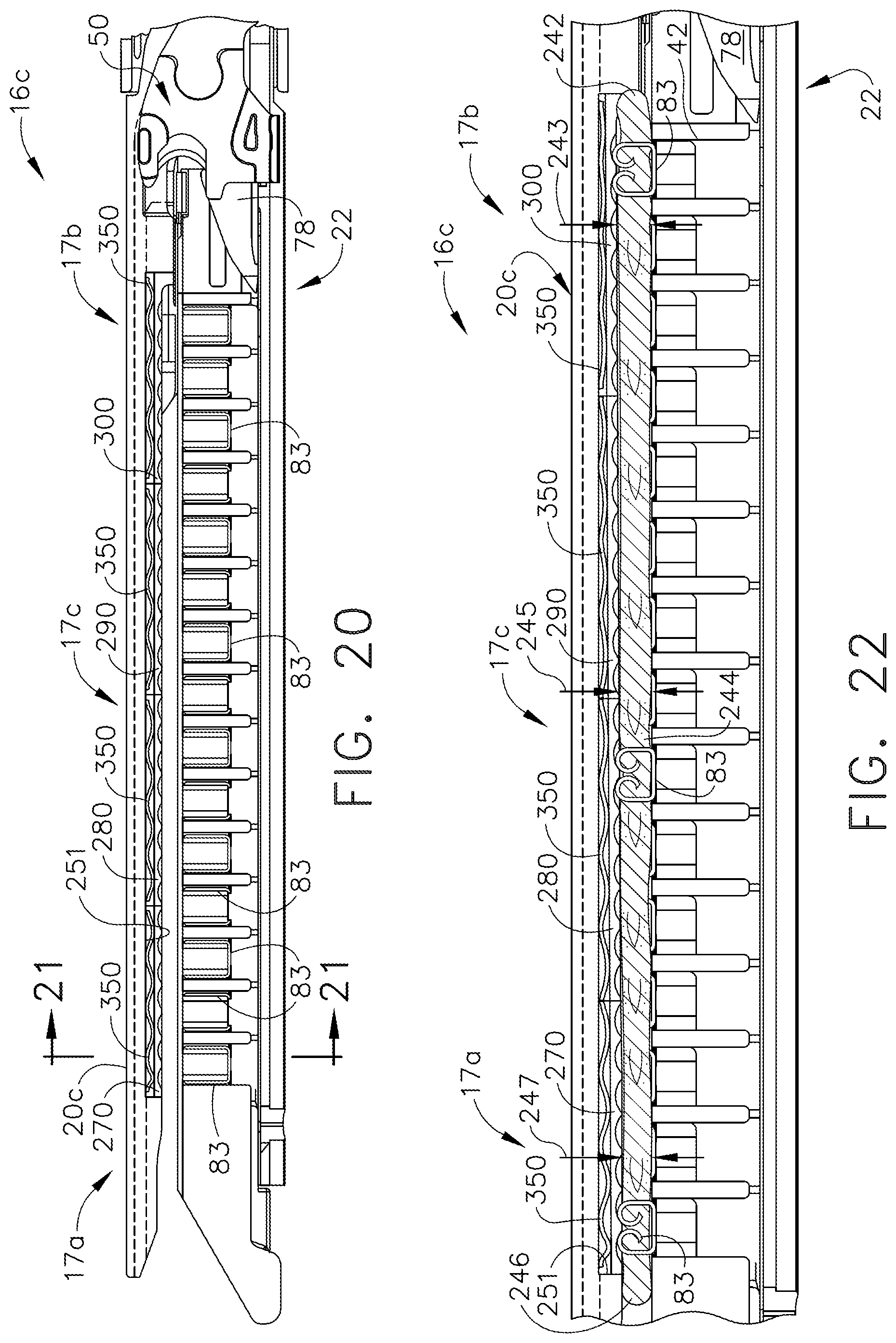
D00016

D00017

D00018
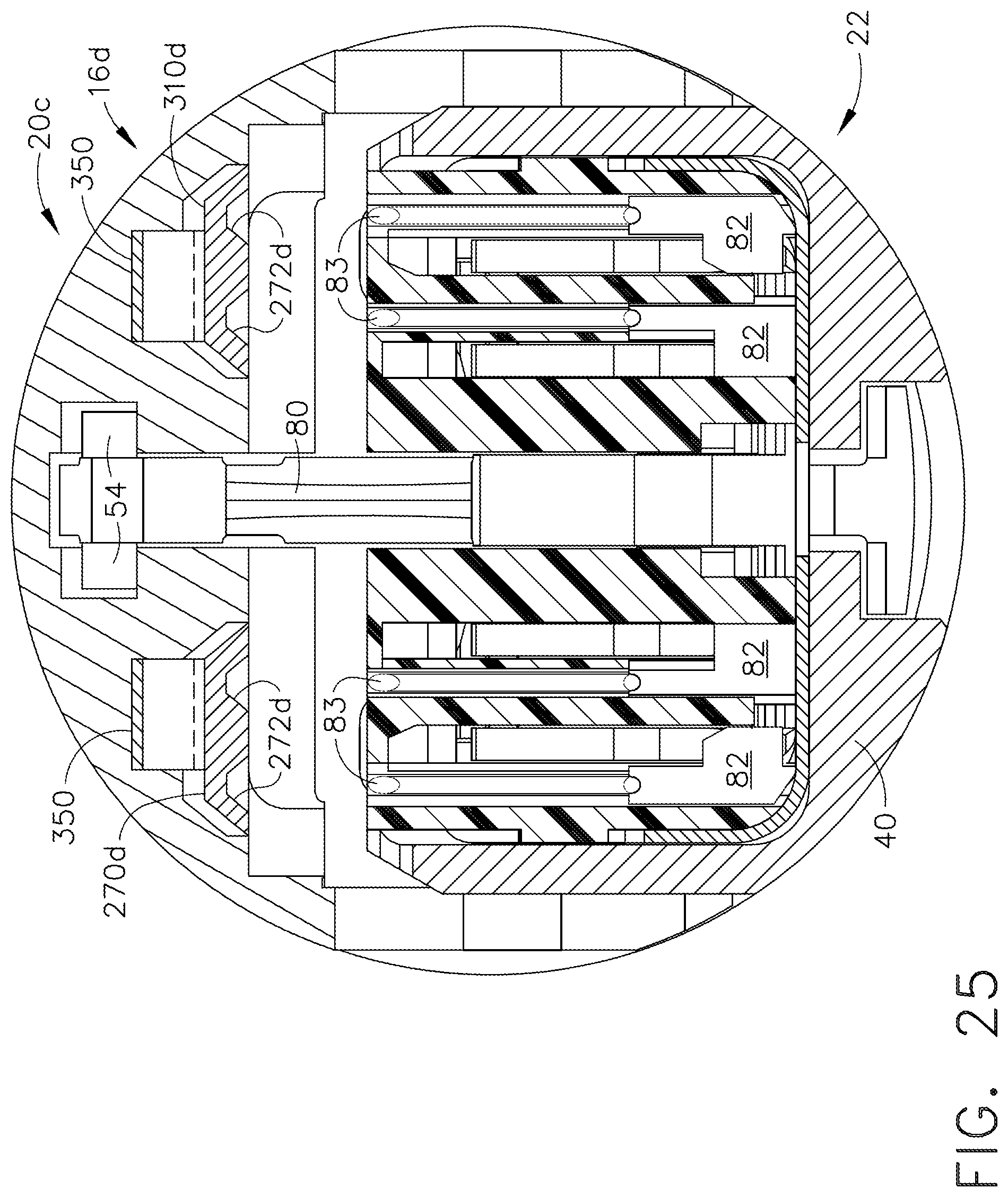
D00019

D00020

D00021
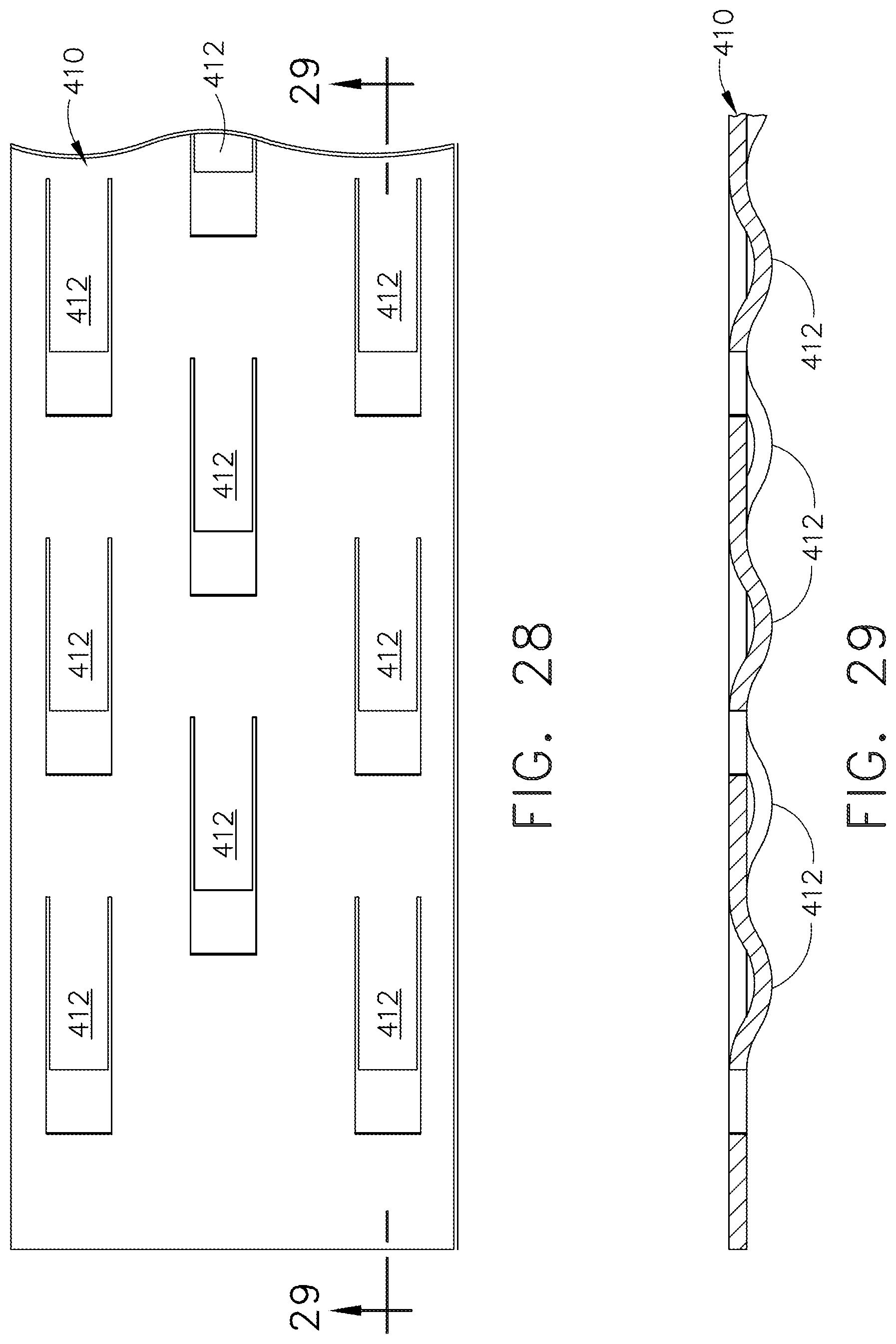
D00022

D00023

D00024

D00025

D00026

D00027

D00028
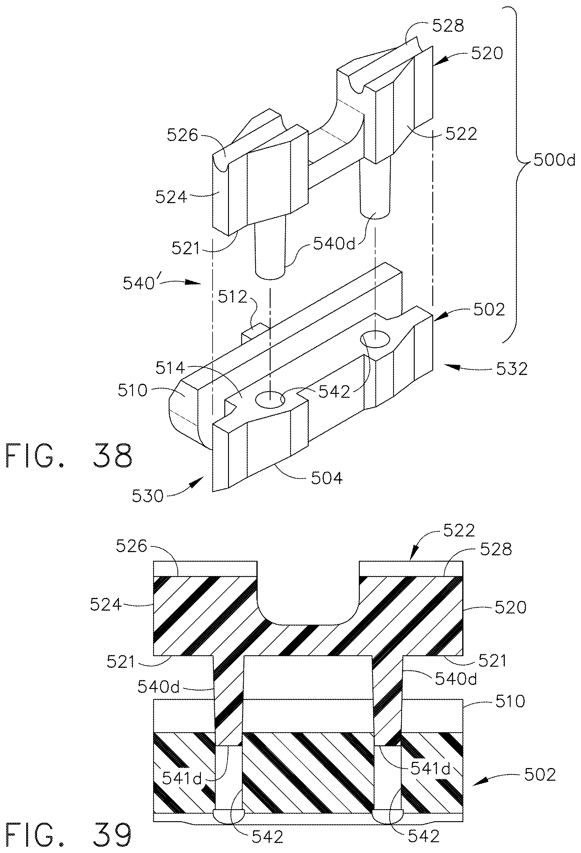
D00029

D00030

D00031

D00032

D00033

D00034
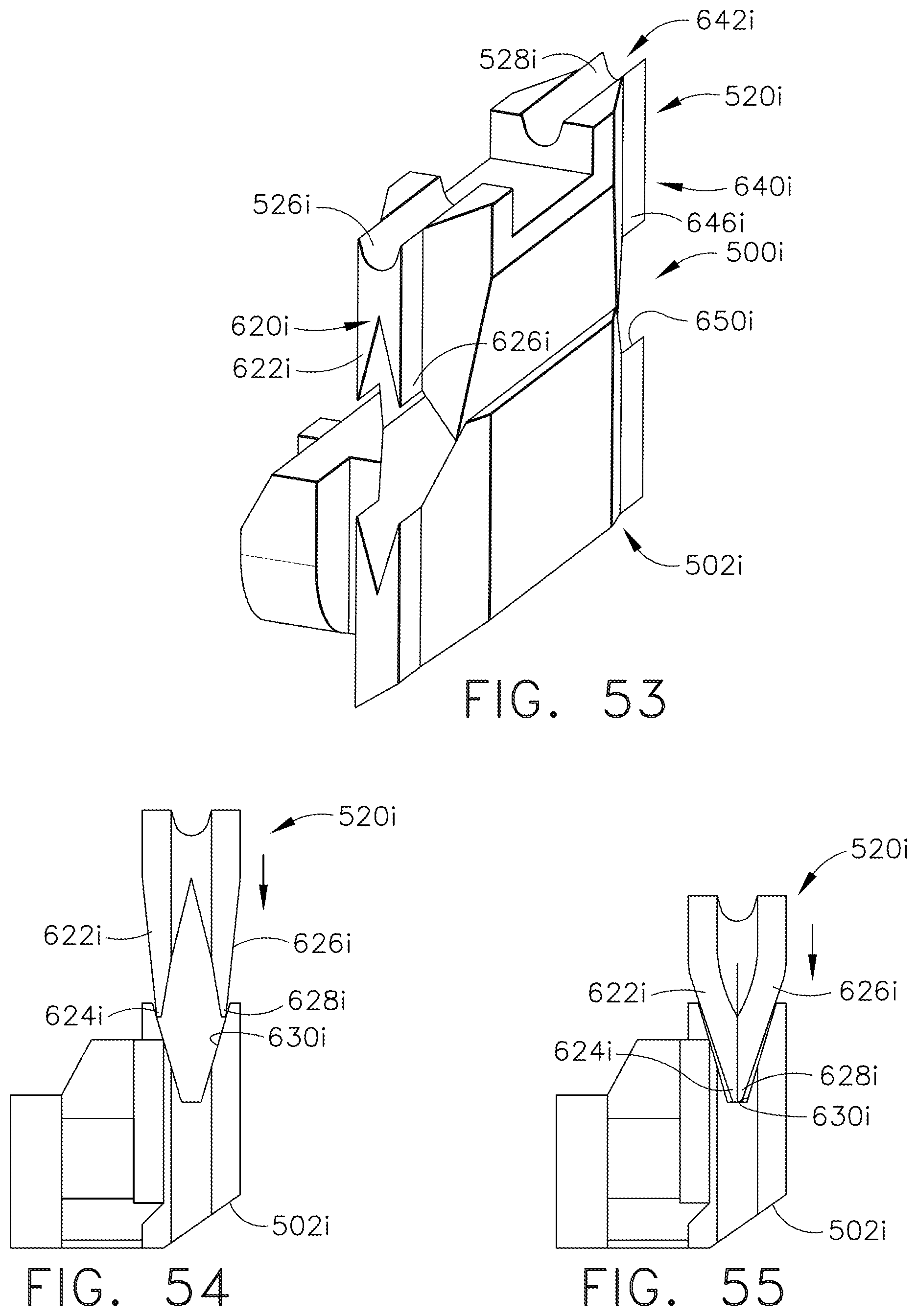
D00035

D00036

D00037

D00038

D00039

D00040

D00041
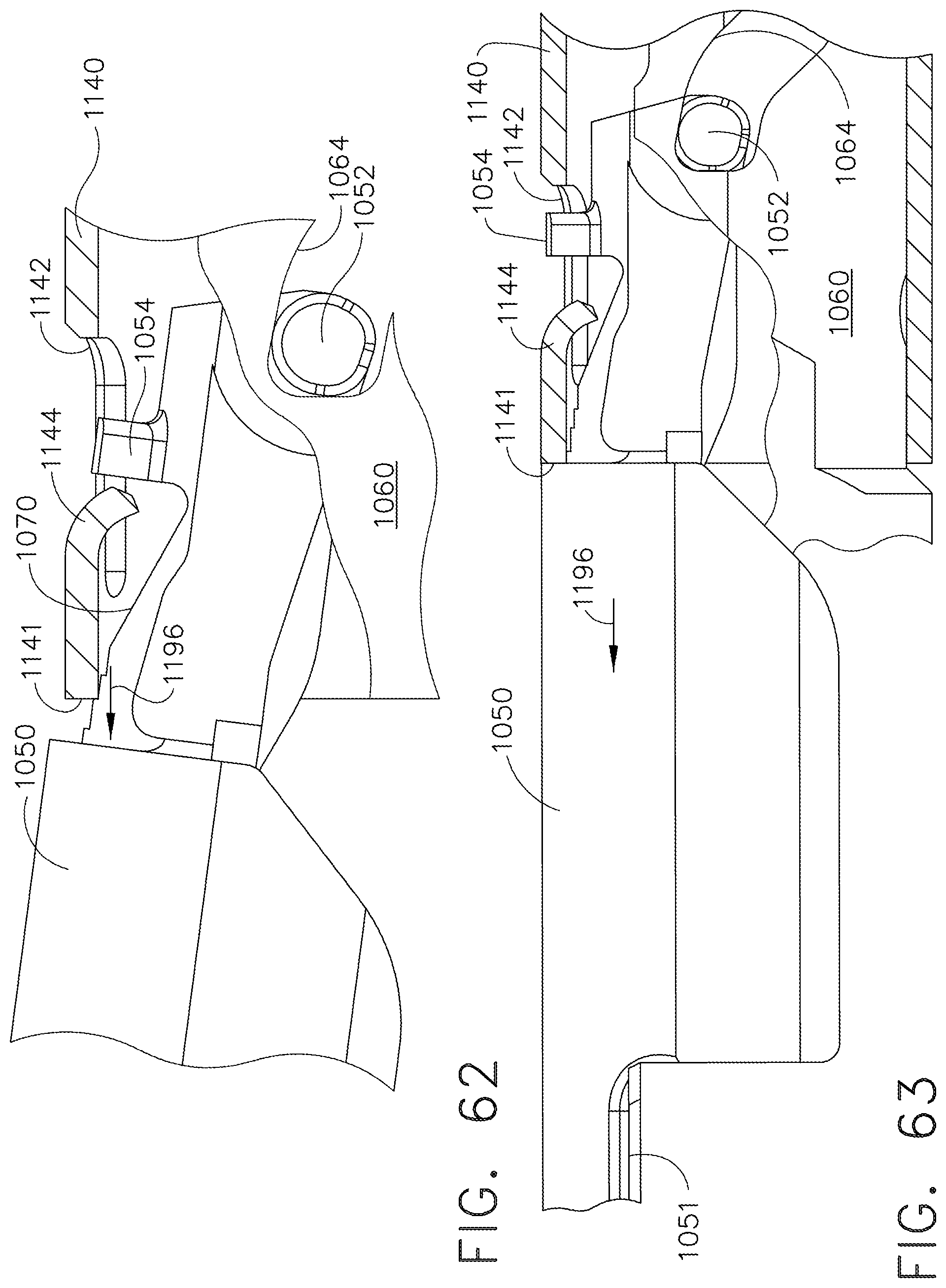
D00042

D00043
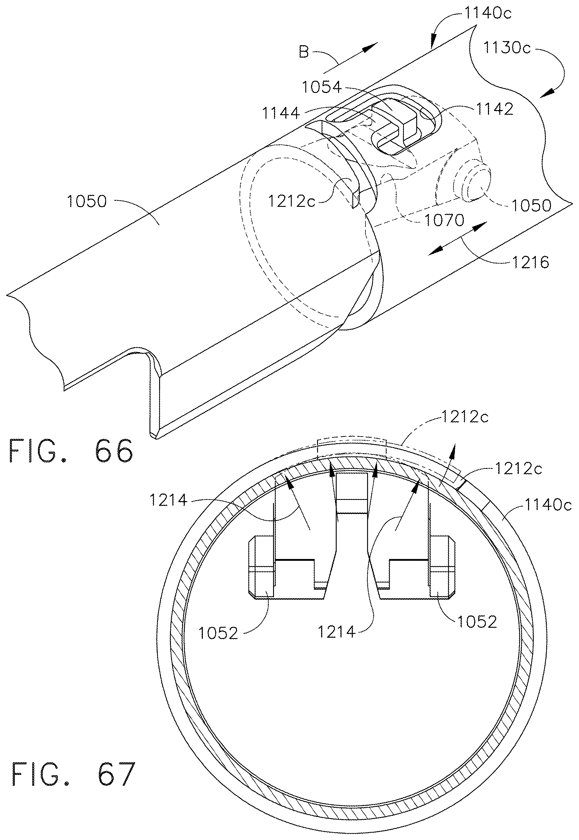
D00044

D00045

D00046
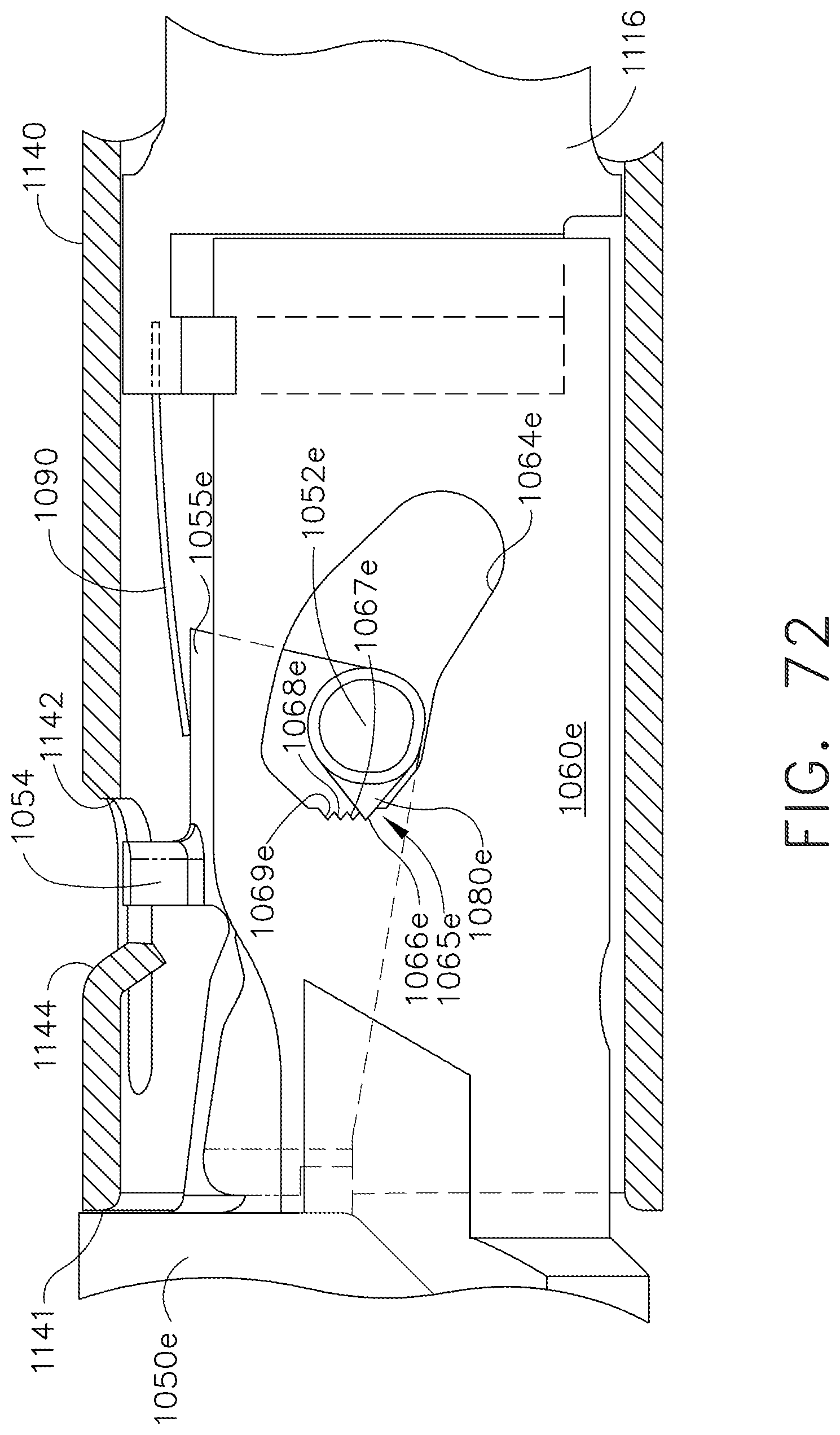
D00047
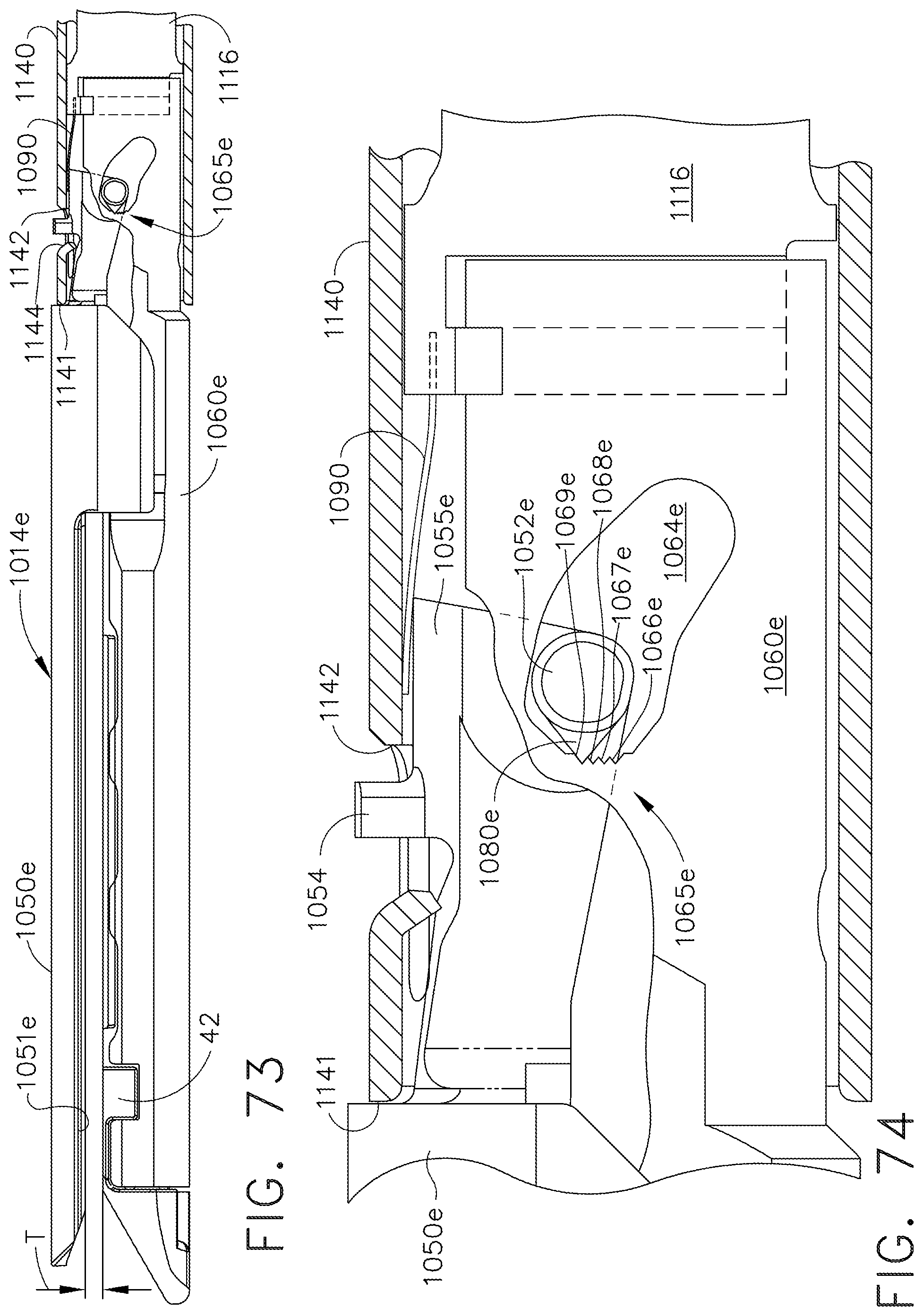
D00048

D00049

D00050

D00051

D00052

D00053

D00054

D00055
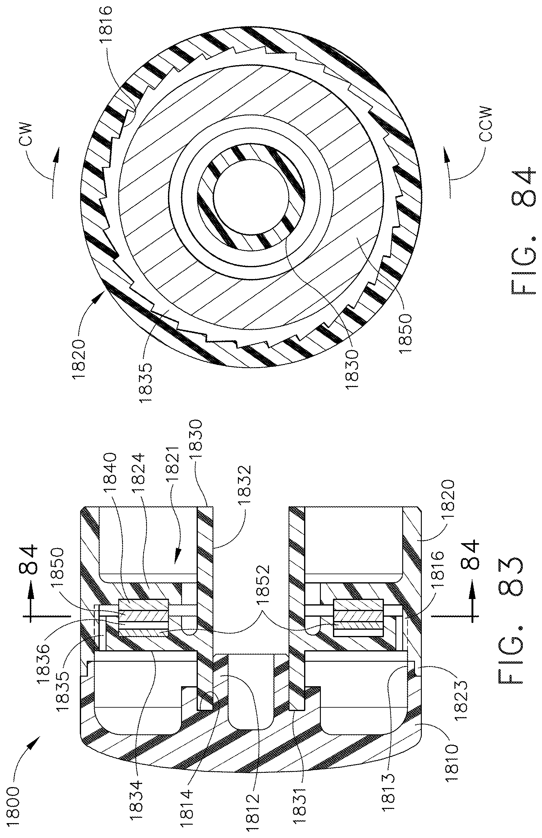
D00056

D00057

D00058

D00059

D00060

D00061

D00062

D00063

D00064

D00065

D00066

D00067

D00068

D00069

D00070

D00071

D00072

D00073

D00074
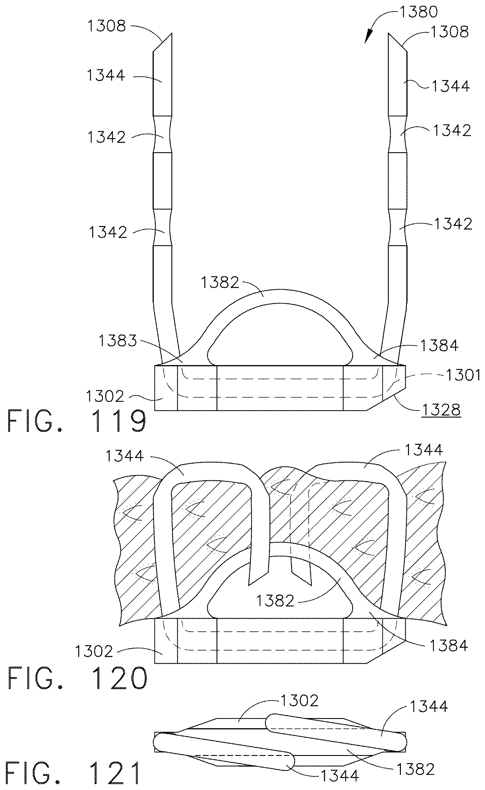
D00075
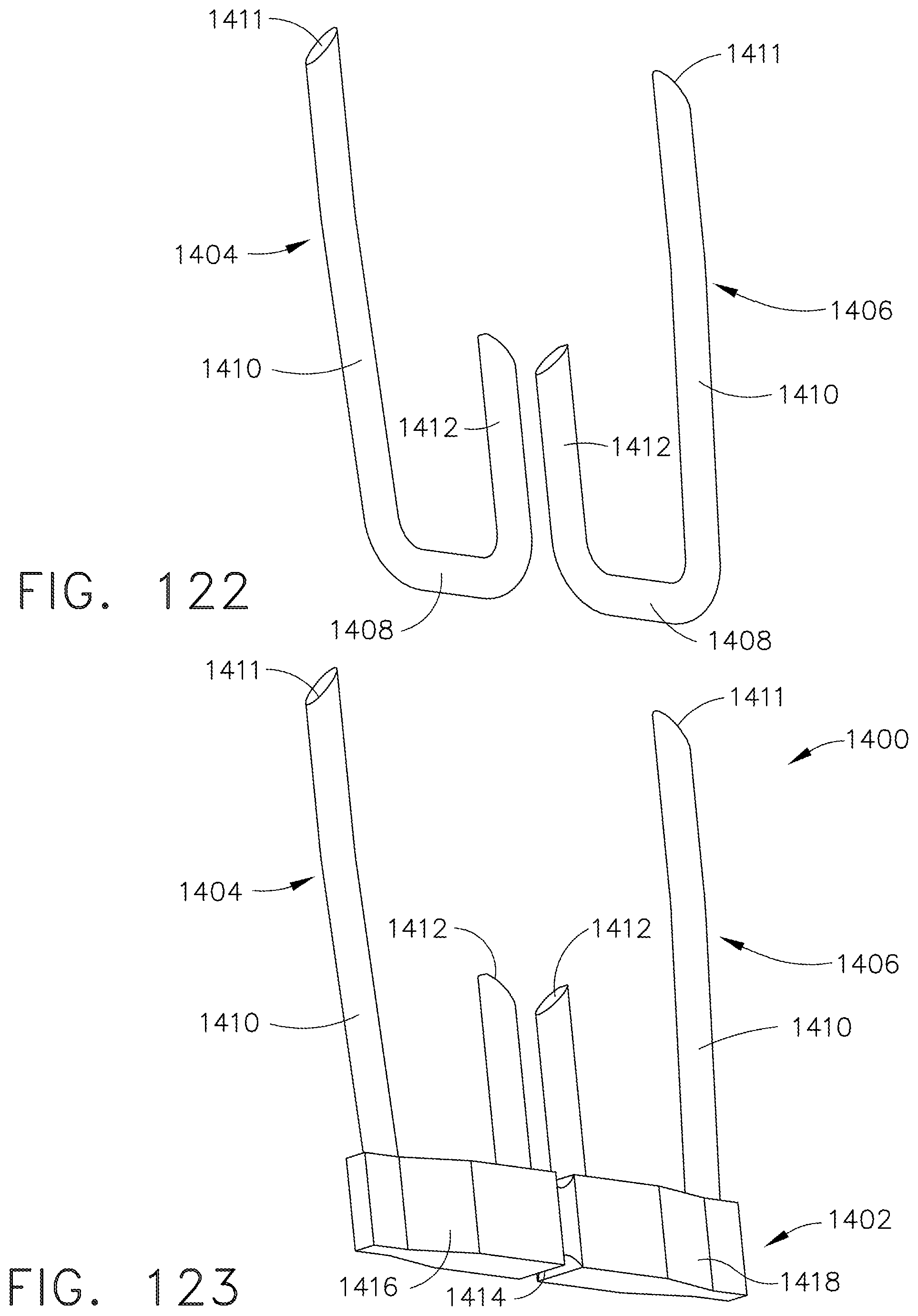
D00076
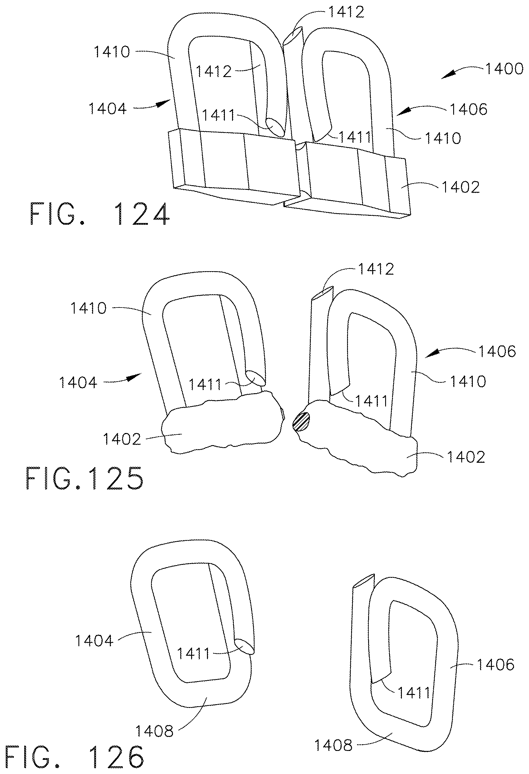
D00077
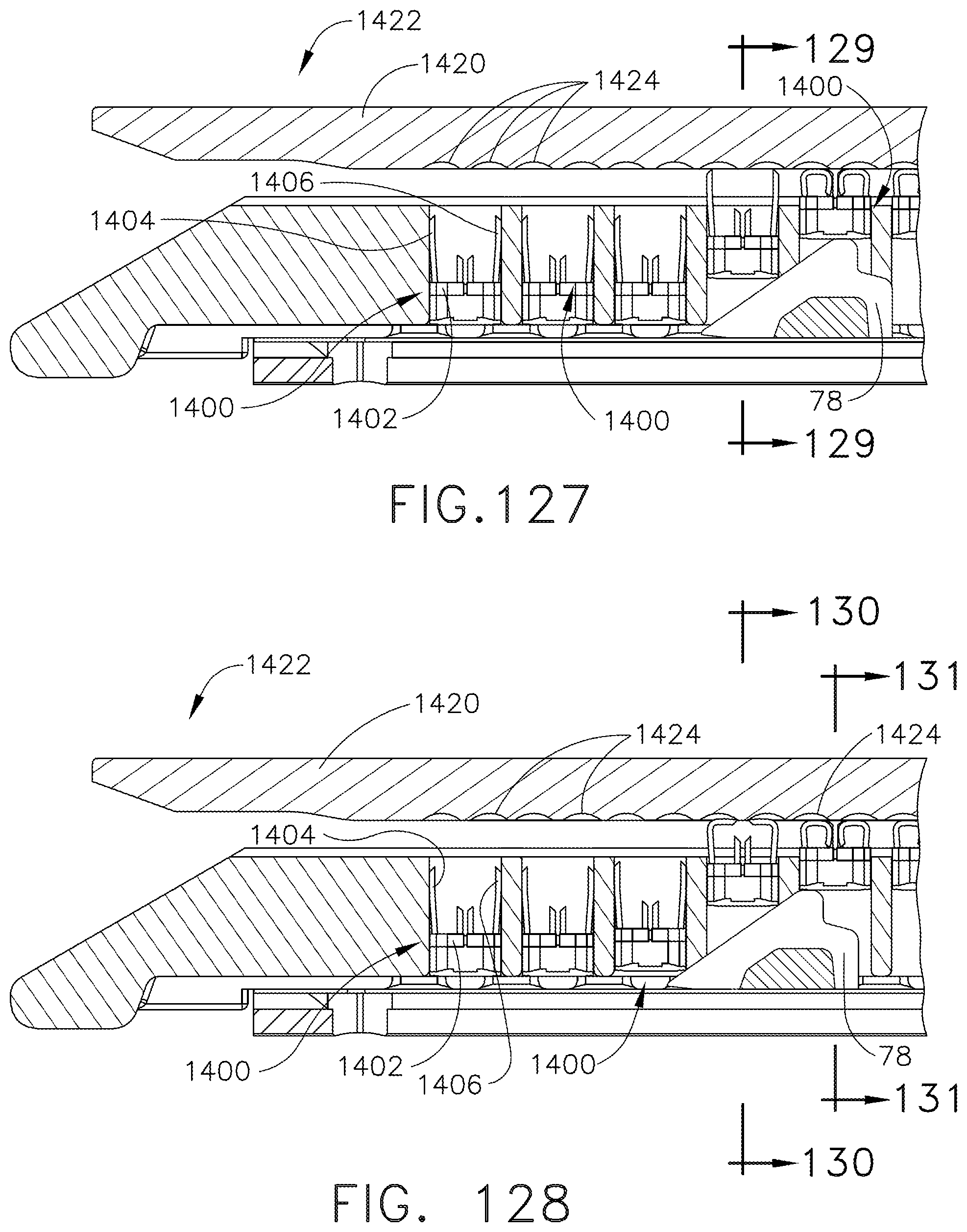
D00078
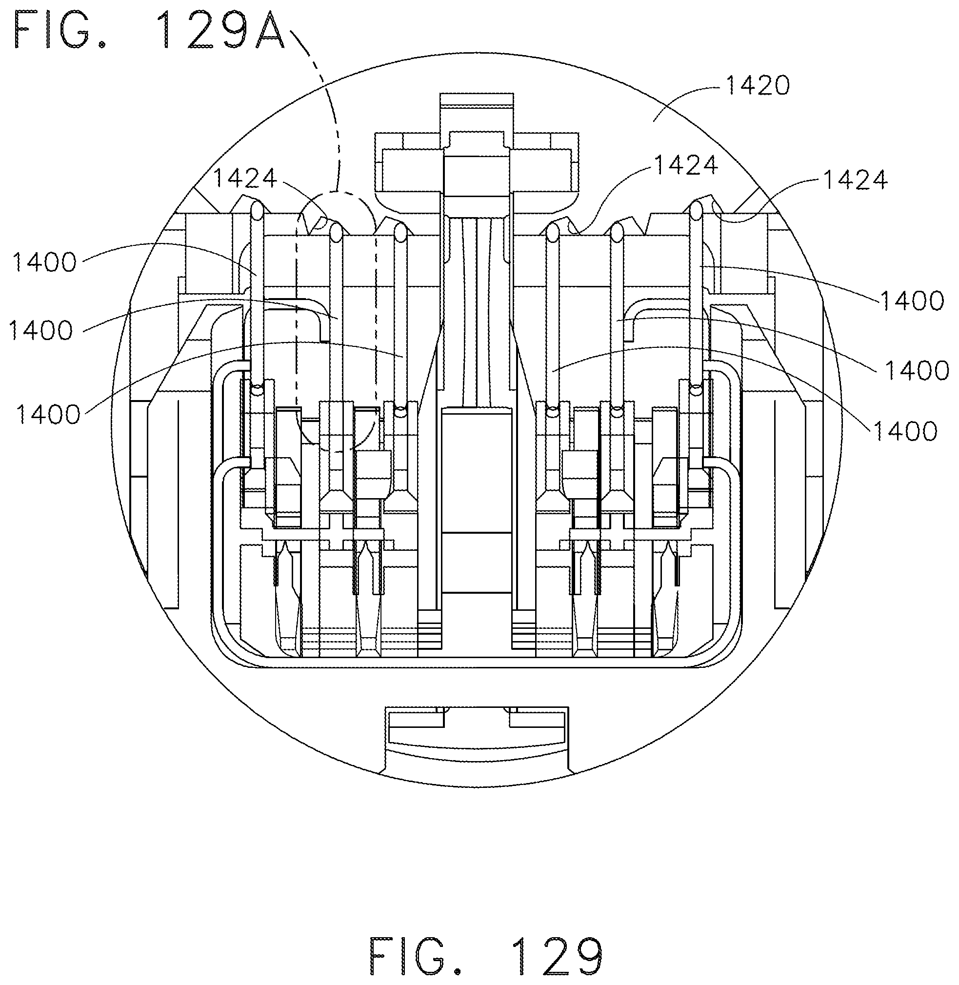
D00079

D00080

D00081

D00082
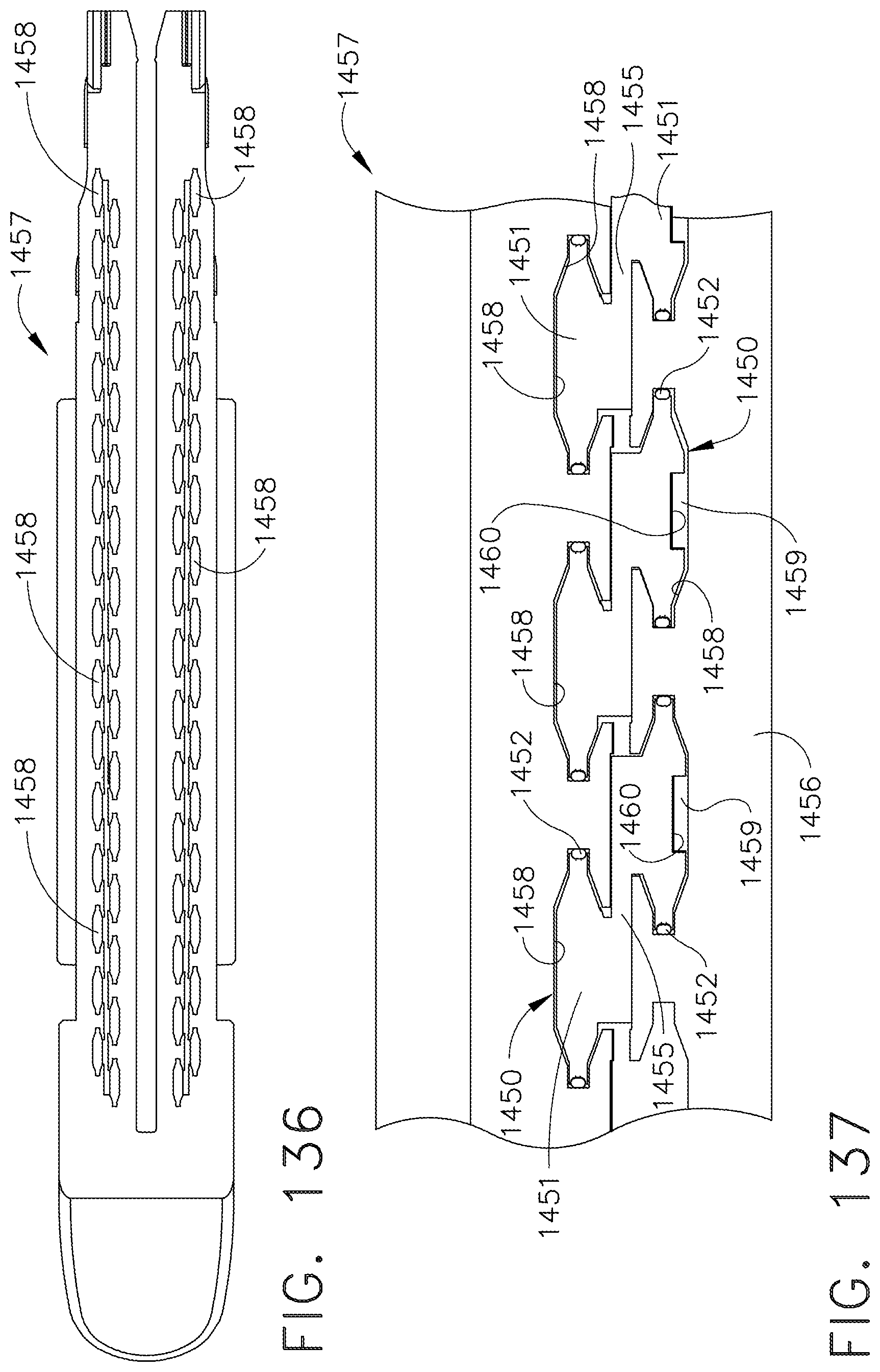
D00083
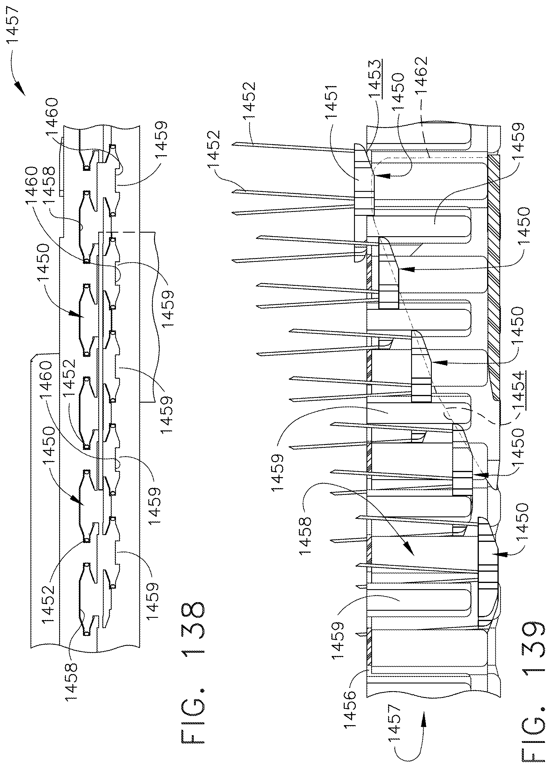
D00084

D00085

D00086

D00087

D00088
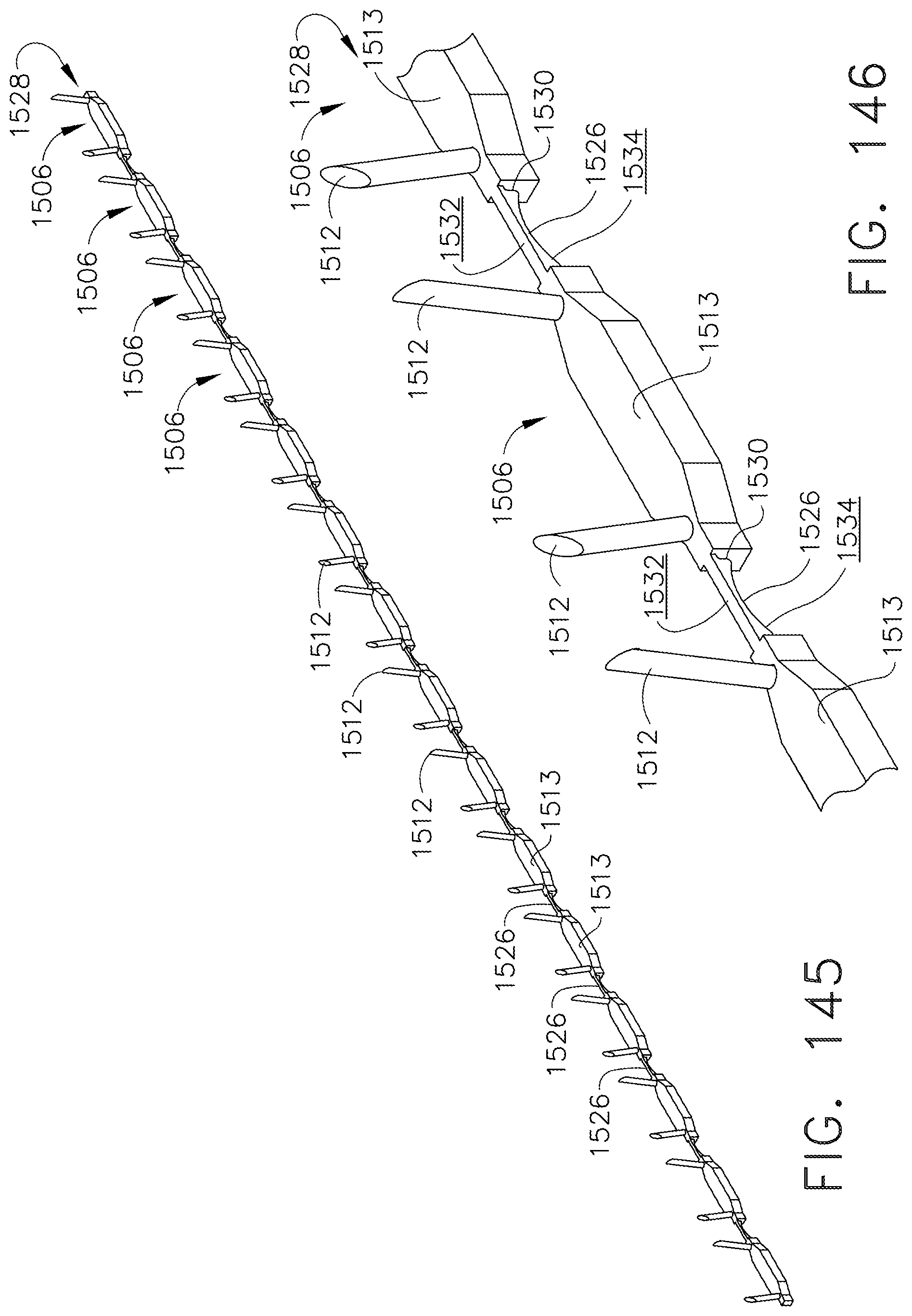
D00089

D00090

D00091

D00092

D00093

D00094

D00095

D00096

D00097

D00098

D00099

D00100
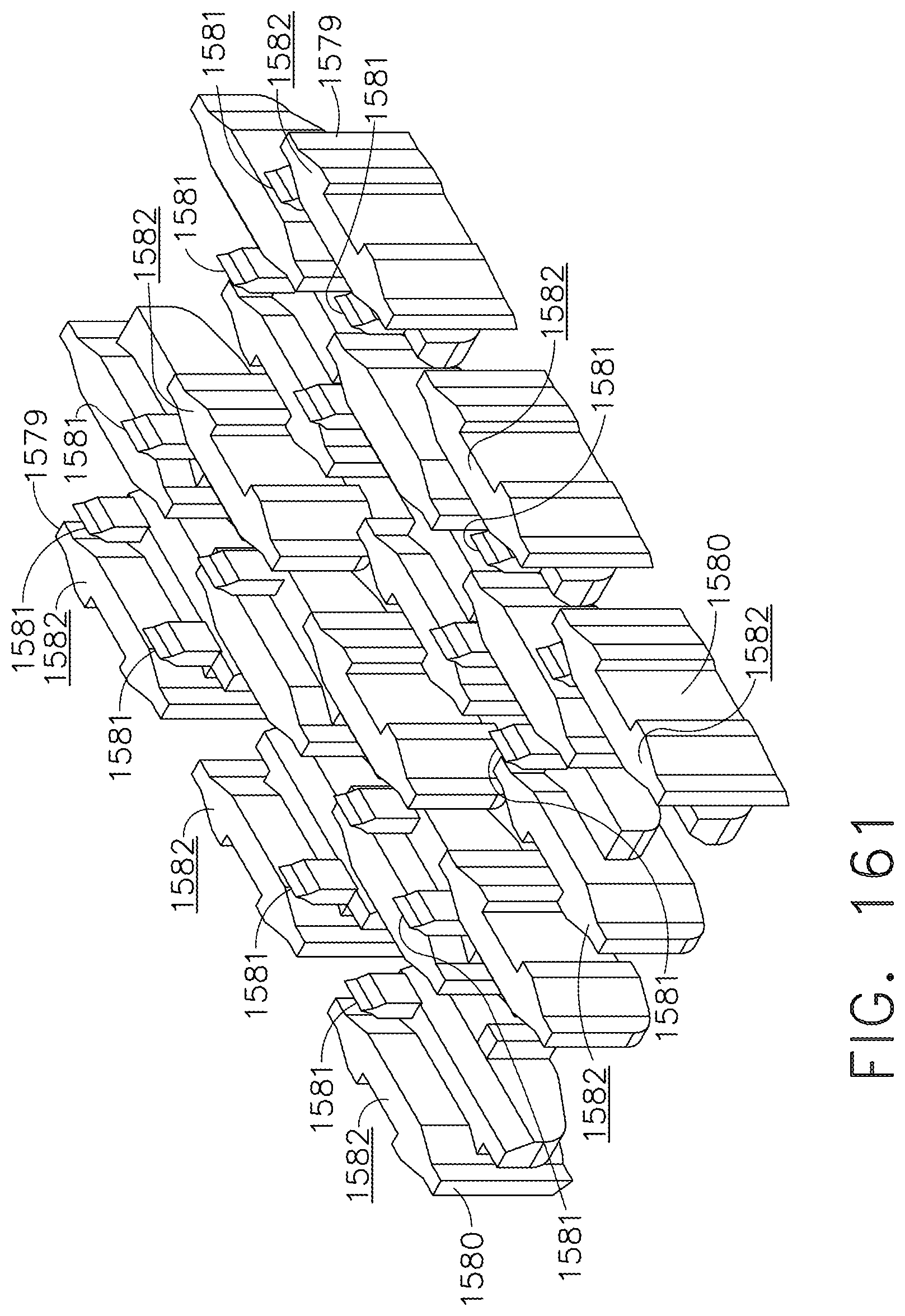
D00101
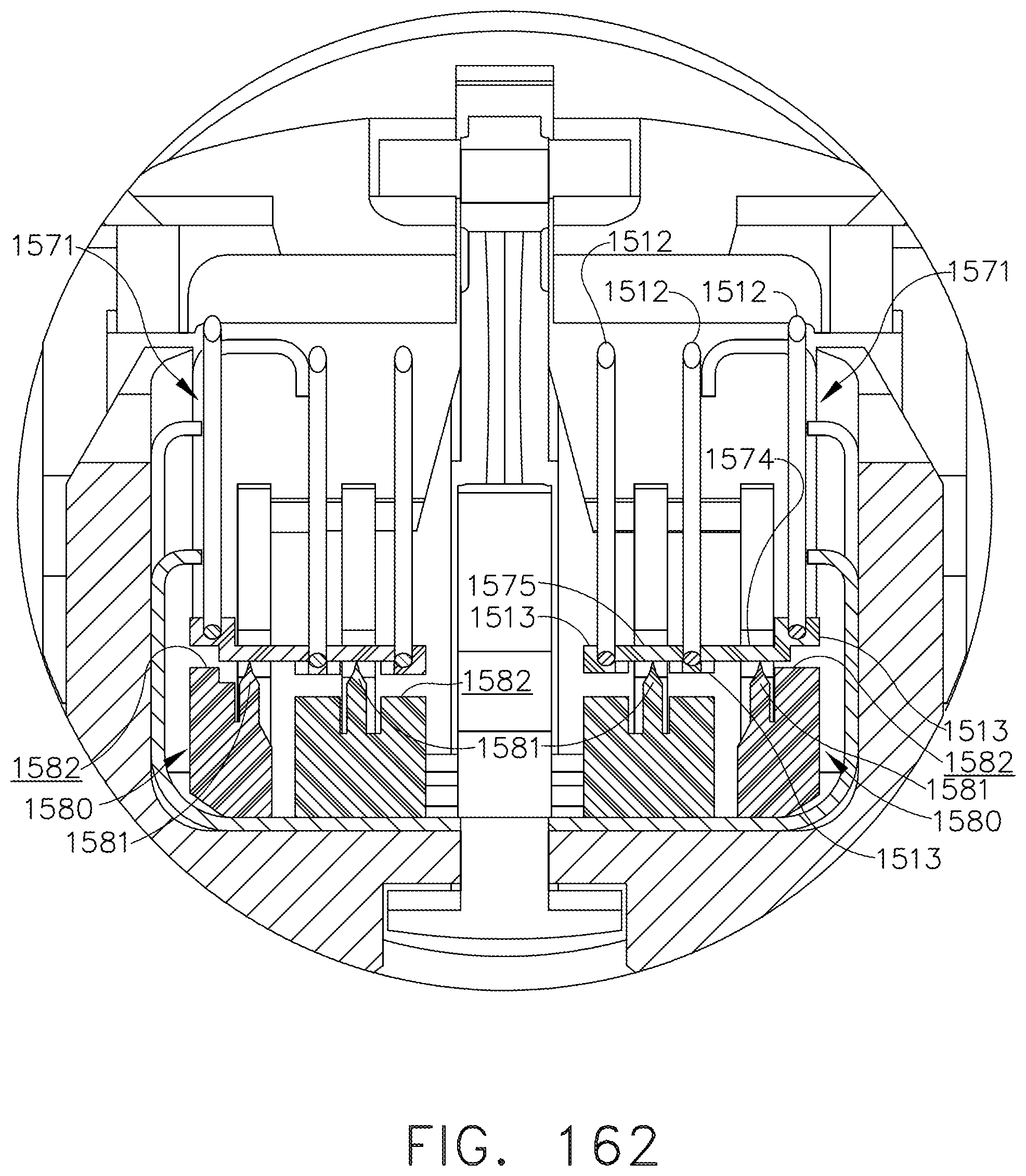
D00102

D00103

D00104

D00105

D00106

D00107

D00108

D00109

D00110
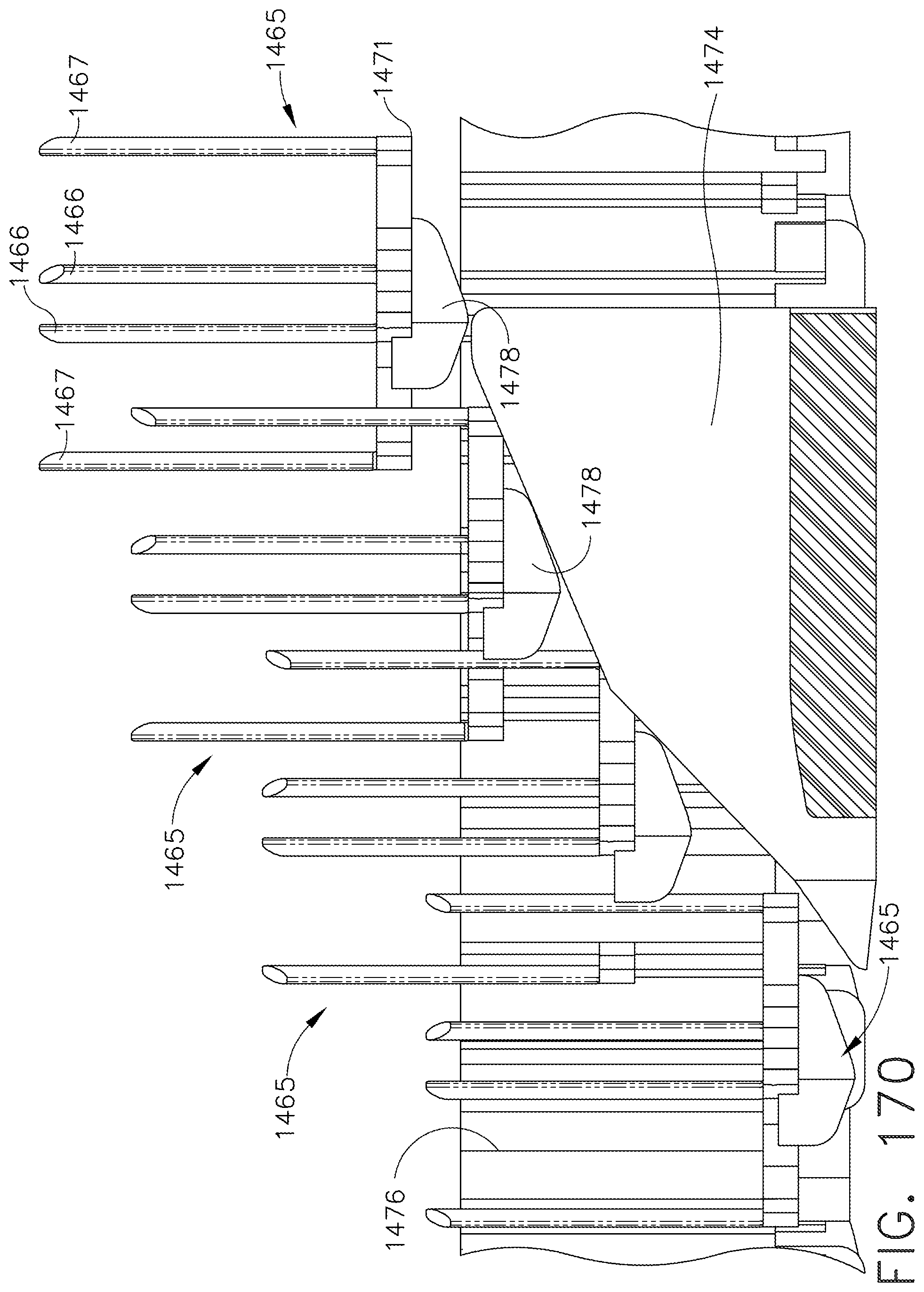
D00111

D00112
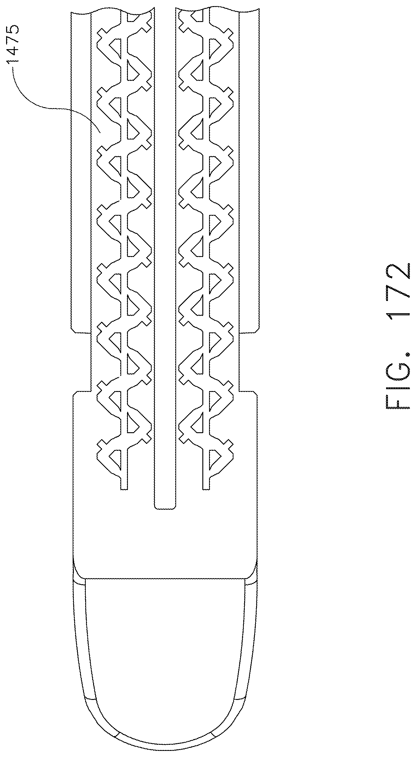
D00113

D00114

D00115
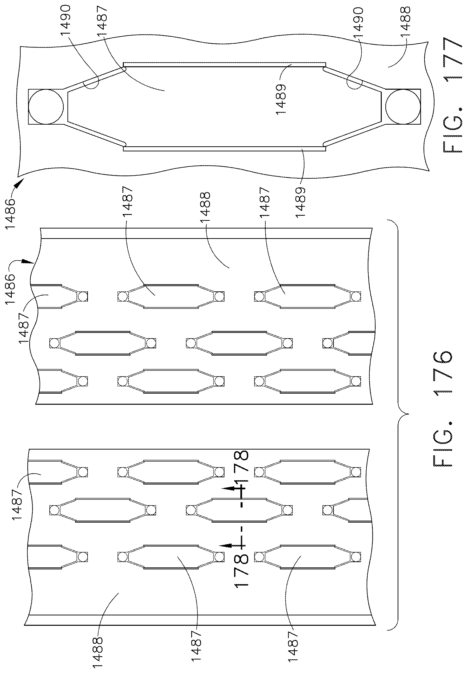
D00116

D00117

D00118
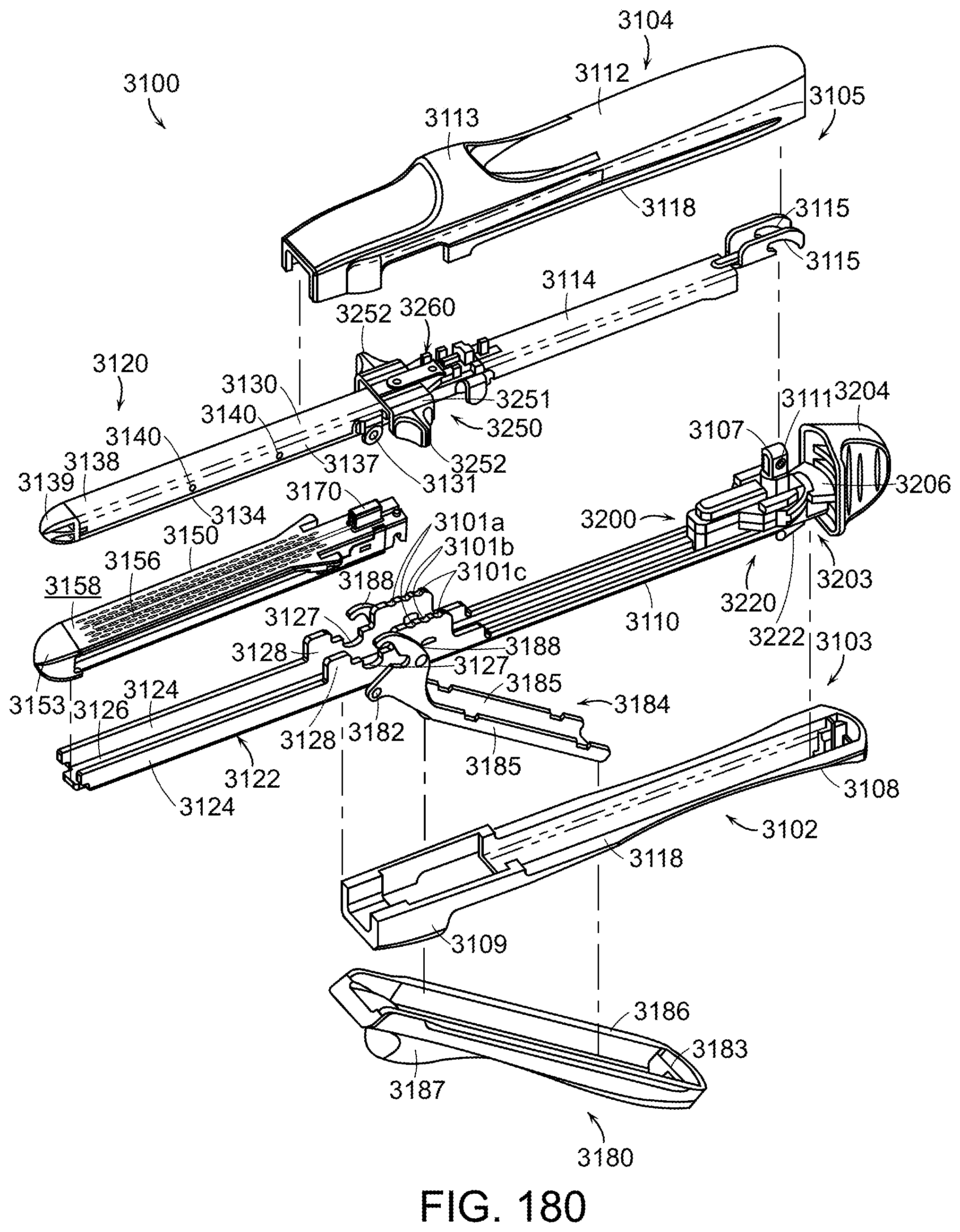
D00119

D00120

D00121

D00122

D00123

D00124

D00125
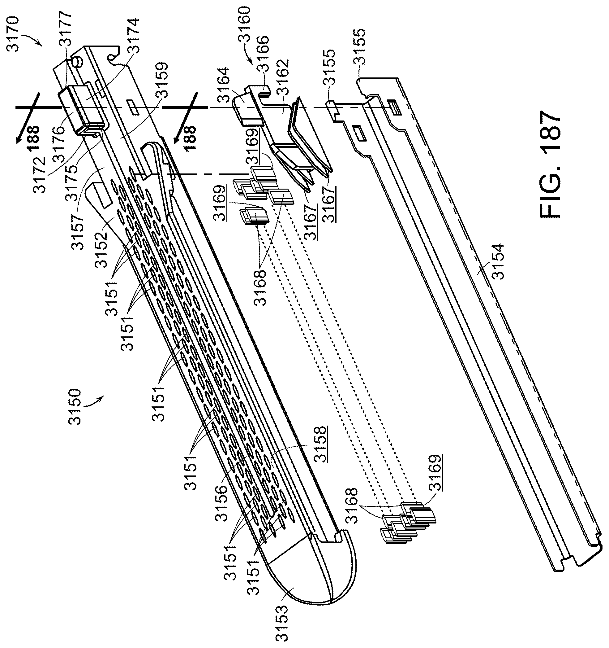
D00126

D00127

D00128

D00129
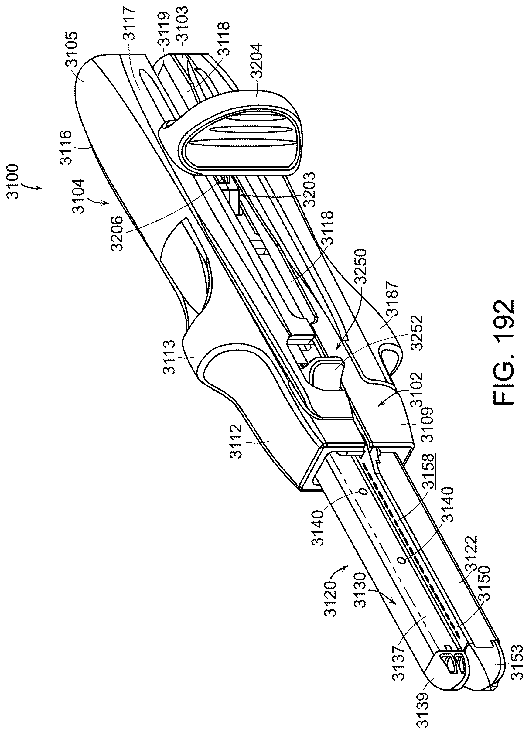
D00130

D00131
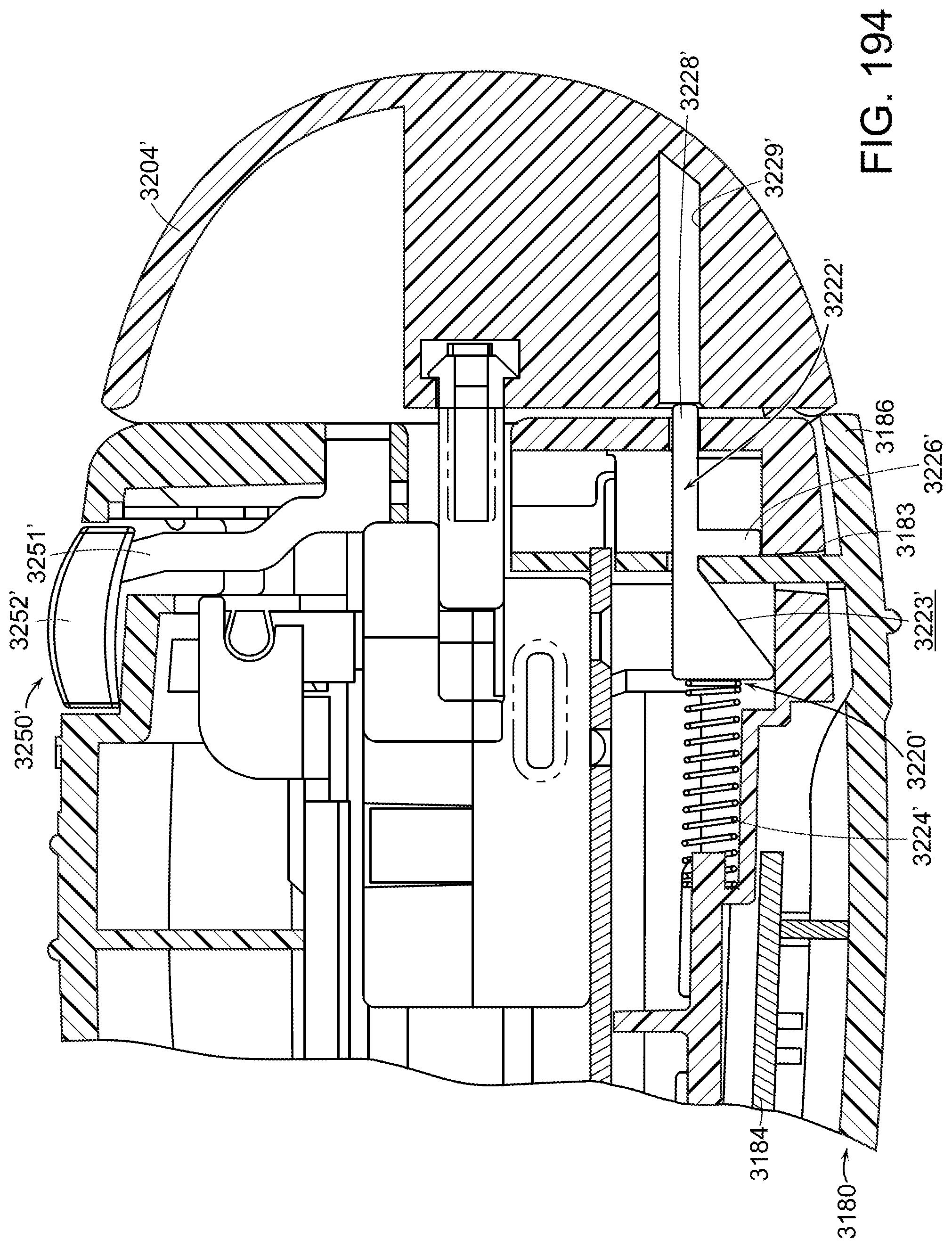
D00132

D00133

D00134
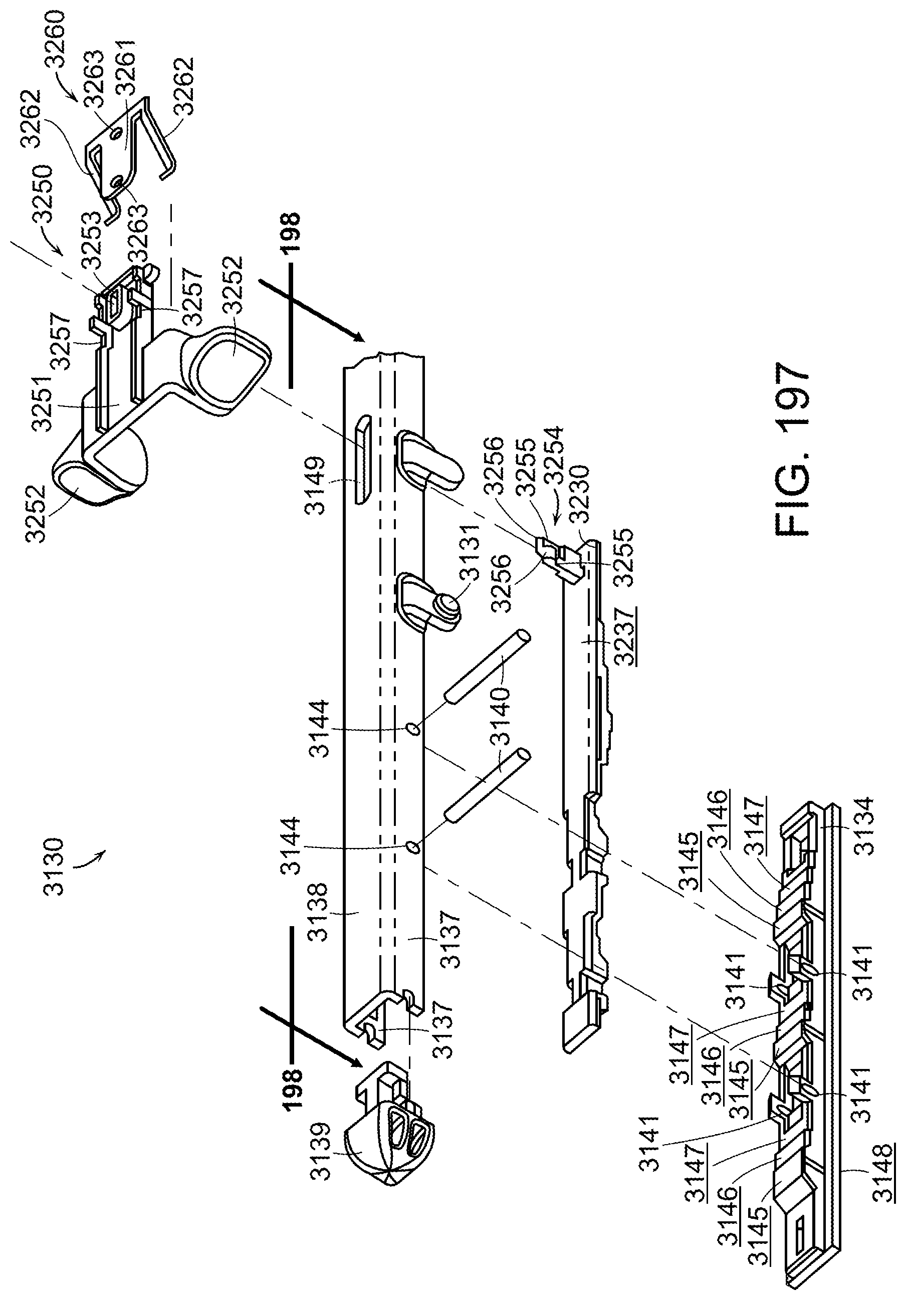
D00135

D00136

D00137

D00138

D00139

D00140

D00141

D00142
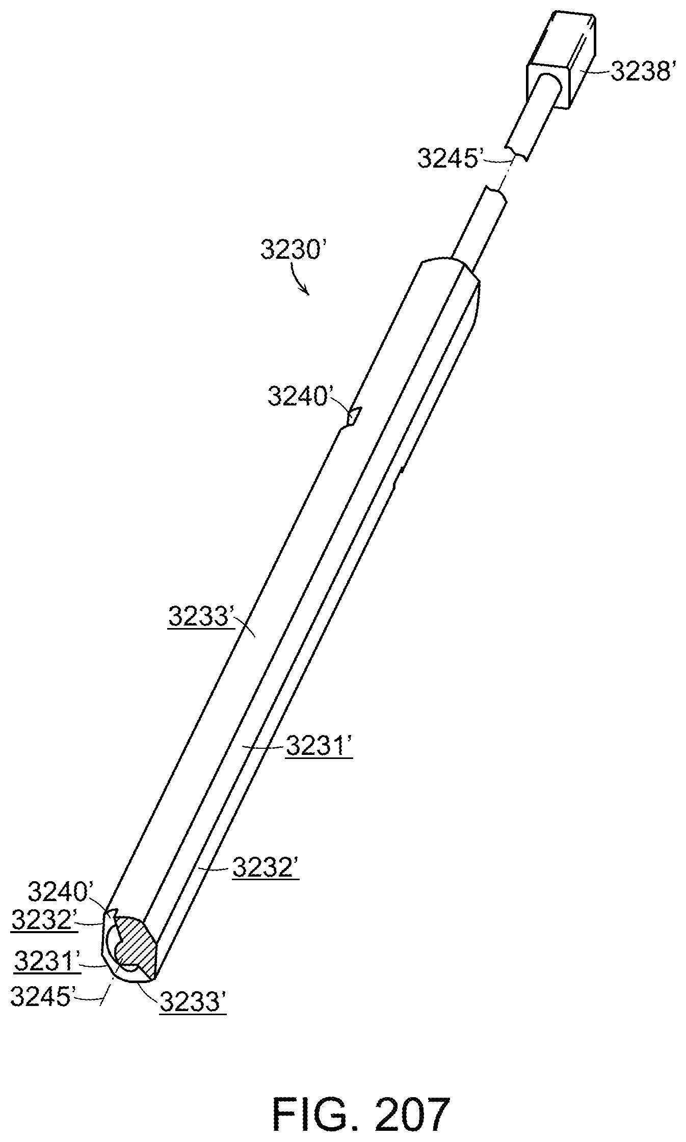
D00143
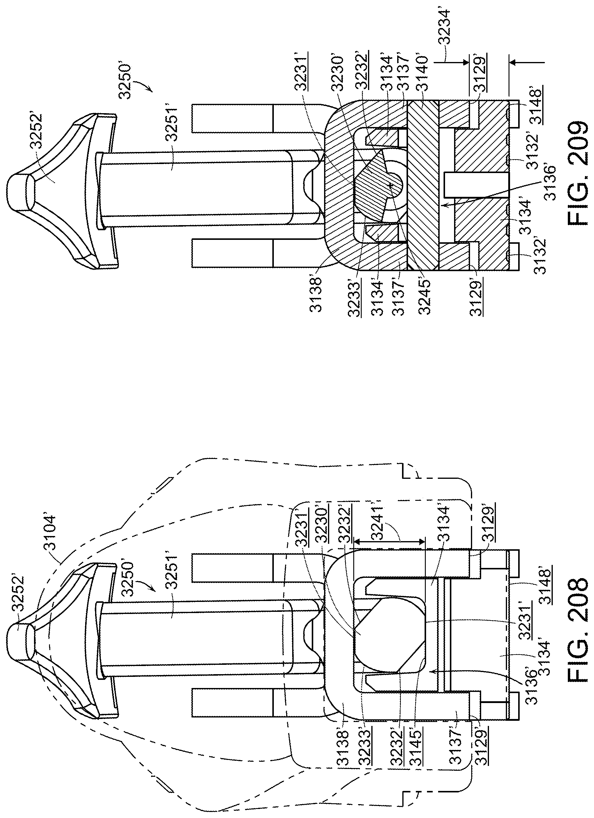
D00144

D00145

D00146
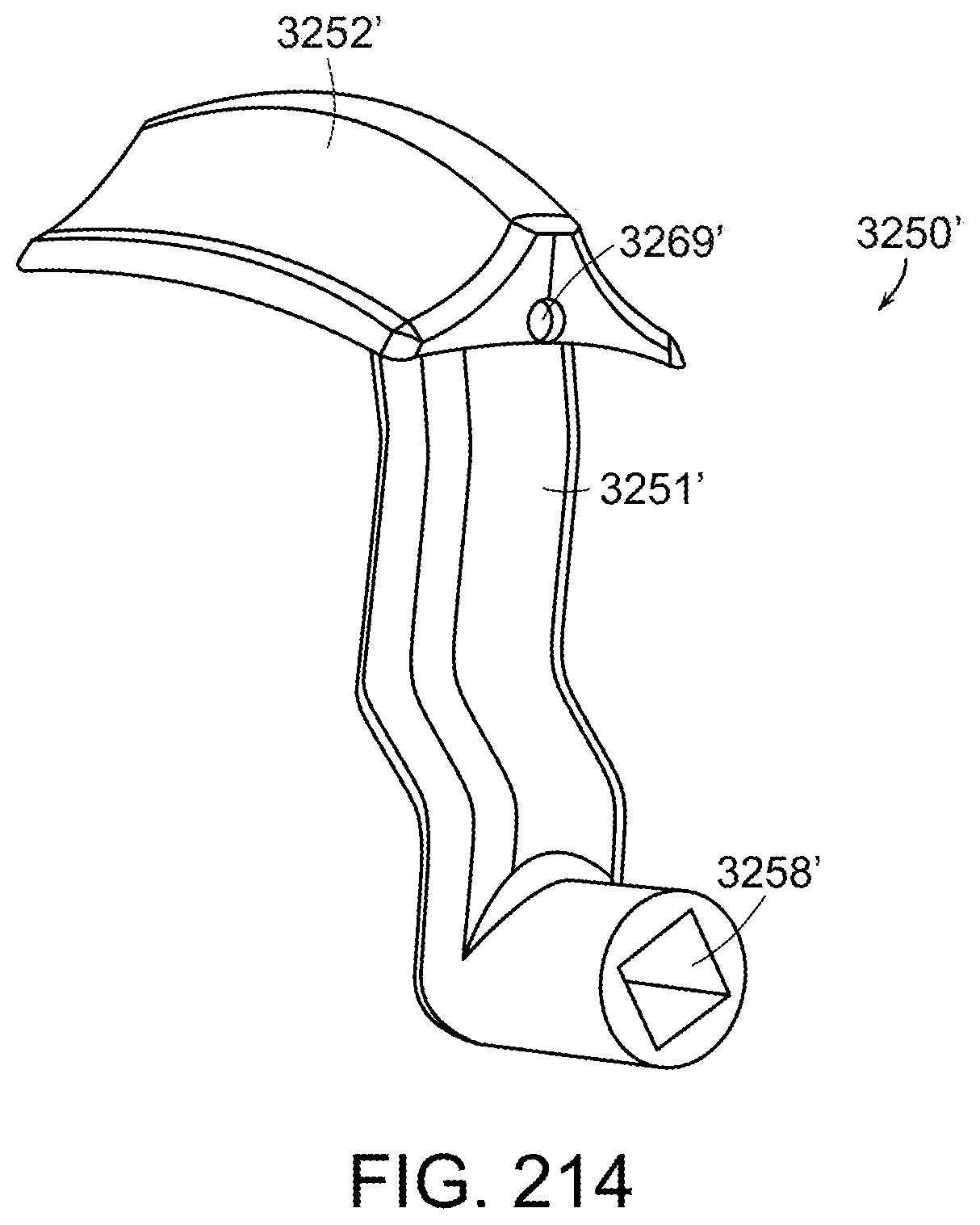
D00147

D00148

D00149

D00150

D00151

D00152

D00153

D00154

D00155

D00156

D00157

D00158

D00159

D00160

D00161

D00162

D00163

D00164
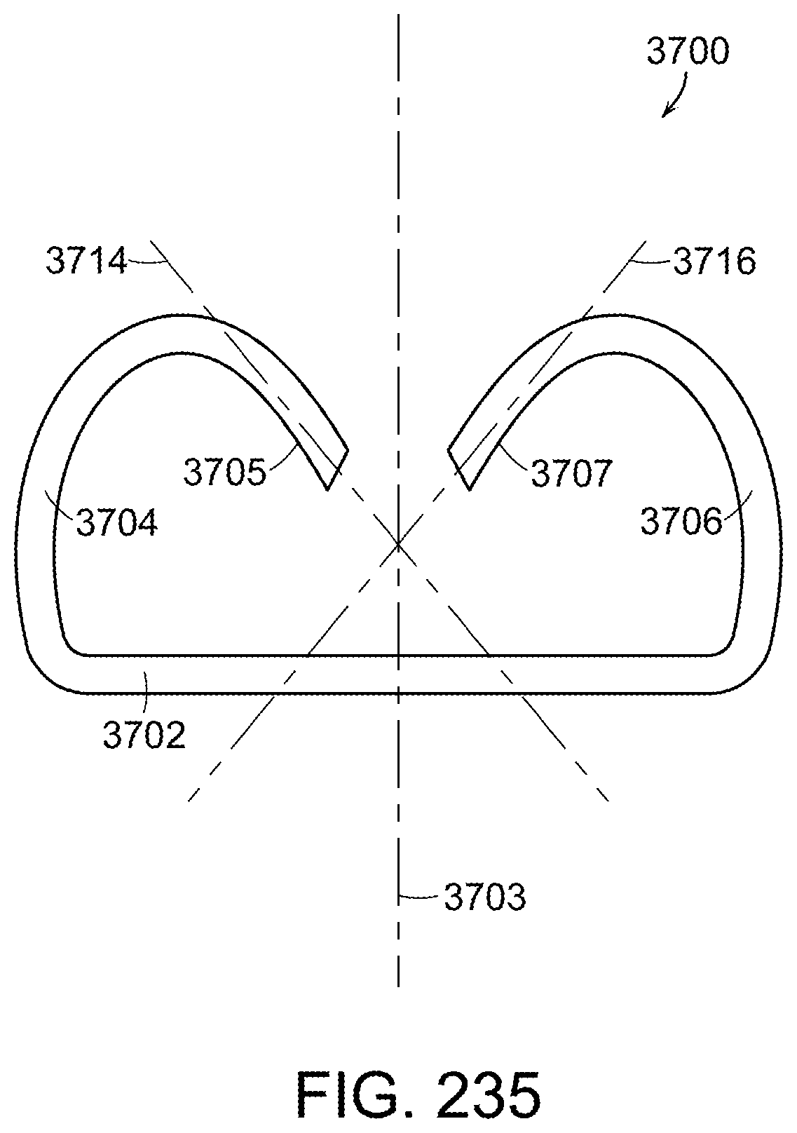
D00165

XML
uspto.report is an independent third-party trademark research tool that is not affiliated, endorsed, or sponsored by the United States Patent and Trademark Office (USPTO) or any other governmental organization. The information provided by uspto.report is based on publicly available data at the time of writing and is intended for informational purposes only.
While we strive to provide accurate and up-to-date information, we do not guarantee the accuracy, completeness, reliability, or suitability of the information displayed on this site. The use of this site is at your own risk. Any reliance you place on such information is therefore strictly at your own risk.
All official trademark data, including owner information, should be verified by visiting the official USPTO website at www.uspto.gov. This site is not intended to replace professional legal advice and should not be used as a substitute for consulting with a legal professional who is knowledgeable about trademark law.