Braided article with internal midsole structure
Bruce , et al.
U.S. patent number 10,674,791 [Application Number 14/565,598] was granted by the patent office on 2020-06-09 for braided article with internal midsole structure. This patent grant is currently assigned to NIKE, Inc.. The grantee listed for this patent is NIKE, Inc.. Invention is credited to Robert M. Bruce, Eun Kyung Lee, Craig K. Sills.


View All Diagrams
| United States Patent | 10,674,791 |
| Bruce , et al. | June 9, 2020 |
Braided article with internal midsole structure
Abstract
A method of making an article of footwear includes temporarily attaching a midsole structure to a last and inserting the midsole structure and footwear last through a braiding machine. A braided structure in the form of an upper is formed. The upper includes a midsole structure disposed within an interior cavity of the upper.
| Inventors: | Bruce; Robert M. (Portland, OR), Lee; Eun Kyung (Beaverton, OR), Sills; Craig K. (Tigard, OR) | ||||||||||
|---|---|---|---|---|---|---|---|---|---|---|---|
| Applicant: |
|
||||||||||
| Assignee: | NIKE, Inc. (Beaverton,
OR) |
||||||||||
| Family ID: | 54352534 | ||||||||||
| Appl. No.: | 14/565,598 | ||||||||||
| Filed: | December 10, 2014 |
Prior Publication Data
| Document Identifier | Publication Date | |
|---|---|---|
| US 20160166007 A1 | Jun 16, 2016 | |
| Current U.S. Class: | 1/1 |
| Current CPC Class: | A43D 11/006 (20130101); A43B 13/125 (20130101); A43B 23/042 (20130101); A43B 1/04 (20130101); D04C 1/06 (20130101); D04C 3/48 (20130101); D10B 2501/043 (20130101) |
| Current International Class: | A43B 23/04 (20060101); D04C 1/06 (20060101); A43D 11/00 (20060101); D04C 3/48 (20060101); A43B 1/04 (20060101); A43B 13/12 (20060101) |
| Field of Search: | ;36/31 ;12/133R,145,146C,128D,128C,139,141,133C ;87/34 |
References Cited [Referenced By]
U.S. Patent Documents
| 165941 | July 1875 | Malhebe |
| 329739 | November 1885 | Heostkels |
| 376372 | January 1888 | Dodge et al. |
| 509241 | November 1893 | Paokaed |
| 578294 | March 1897 | Leayitt |
| 586137 | July 1897 | Medger |
| 621922 | March 1899 | Kelsall |
| 1182325 | May 1916 | Sedmak |
| 1318888 | October 1919 | Le Carpentier |
| 1527344 | February 1925 | Bente et al. |
| 1538160 | May 1925 | Bosebeck |
| 1540903 | June 1925 | Santoyo |
| 1554325 | September 1925 | Bente |
| 1583273 | May 1926 | Bosebeck |
| 1597934 | August 1926 | Stimpson |
| 1600621 | September 1926 | Buek, Jr. |
| 1622021 | March 1927 | Birkin et al. |
| 1637716 | August 1927 | Turck |
| 1663319 | March 1928 | Snell |
| 1687643 | October 1928 | Berliner |
| 1713307 | May 1929 | Stritter |
| 1717183 | June 1929 | Brenner |
| 1803554 | May 1931 | Knilans |
| 1828320 | October 1931 | Daniels |
| 1832691 | November 1931 | David |
| 1864254 | June 1932 | Meyer |
| 1877080 | September 1932 | Teshima |
| 1887643 | November 1932 | Huber |
| 1949318 | February 1934 | Markowsky |
| 2001293 | May 1935 | Wilson |
| 2022350 | November 1935 | Huber |
| 2091215 | August 1937 | Price |
| 2144689 | January 1939 | Roberts |
| 2147197 | February 1939 | Glidden |
| 2161472 | June 1939 | Hurwit |
| 2162472 | June 1939 | Scharf |
| 2165092 | July 1939 | Daniels |
| 2188640 | January 1940 | Bloch et al. |
| RE21392 | March 1940 | Hurwit |
| 2271888 | February 1942 | Manley |
| 2311959 | February 1943 | Nurk |
| D137767 | April 1944 | Goldstein |
| 2382559 | August 1945 | Goldstein |
| 2412808 | December 1946 | Goldstein |
| 2521072 | September 1950 | Lovell |
| D164847 | October 1951 | Dronoff |
| 2586045 | February 1952 | Hoza |
| 2617129 | November 1952 | Petze |
| 2641004 | June 1953 | Whiting et al. |
| 2675631 | April 1954 | Doughty |
| 2679117 | May 1954 | Reed |
| 2701887 | February 1955 | Nolan |
| 2936670 | May 1960 | Erwin |
| 3052904 | September 1962 | Reid |
| 3257677 | June 1966 | Batchelder |
| 3282757 | November 1966 | Brussee |
| 3397847 | August 1968 | Thaden |
| 3474478 | October 1969 | Batchelder et al. |
| 3504450 | April 1970 | Steadman et al. |
| 3525110 | August 1970 | Rubico |
| 3586058 | June 1971 | Ahrens et al. |
| 3619838 | November 1971 | Winkler |
| 3745600 | July 1973 | Rubico et al. |
| 3805667 | April 1974 | Orser |
| 3821827 | July 1974 | Nadler |
| 4134955 | January 1979 | Hanrahan, Jr. et al. |
| 4149249 | April 1979 | Pavkovich |
| 4194249 | March 1980 | Thorneburg |
| 4222183 | September 1980 | Haddox |
| 4232458 | November 1980 | Bartels |
| 4275638 | June 1981 | DeYoung |
| 4341097 | July 1982 | Cassidy et al. |
| 4351889 | September 1982 | Sundberg |
| 4394803 | July 1983 | Goldstein |
| 4430811 | February 1984 | Okada |
| 4447967 | May 1984 | Zaino |
| 4519290 | May 1985 | Inman et al. |
| 4587749 | May 1986 | Berlese |
| 4591155 | May 1986 | Adachi |
| 4629650 | December 1986 | Kataoka |
| 4640027 | February 1987 | Berlese |
| 4662088 | May 1987 | Autry et al. |
| 4719837 | January 1988 | McConnell et al. |
| 4785558 | November 1988 | Shiomura |
| 4847063 | June 1989 | Smith |
| 4848745 | July 1989 | Bohannan et al. |
| 4857124 | August 1989 | Shobert et al. |
| 4882858 | November 1989 | Signori |
| 4885973 | December 1989 | Spain |
| 4916997 | April 1990 | Spain |
| 4919388 | April 1990 | Koike et al. |
| 4974275 | December 1990 | Backes et al. |
| 4976812 | December 1990 | McConnell et al. |
| 4992313 | February 1991 | Shobert et al. |
| 5001961 | March 1991 | Spain |
| D315823 | April 1991 | Signori |
| 5067525 | November 1991 | Tsuzuki et al. |
| 5121329 | June 1992 | Crump et al. |
| 5201952 | April 1993 | Yahagi et al. |
| 5203249 | April 1993 | Adams et al. |
| 5257571 | November 1993 | Richardson |
| 5287790 | February 1994 | Akiyama et al. |
| 5335517 | August 1994 | Throneburg et al. |
| 5345638 | September 1994 | Nishida |
| 5348056 | September 1994 | Tsuzuki |
| 5361674 | November 1994 | Akiyama et al. |
| 5381610 | January 1995 | Hanson |
| 5388497 | February 1995 | Akiyama et al. |
| 5396829 | March 1995 | Akiyama et al. |
| 5398586 | March 1995 | Akiyama |
| 5439215 | August 1995 | Ratchford |
| 5476027 | December 1995 | Uchida et al. |
| 5647150 | July 1997 | Romanato et al. |
| 5732413 | March 1998 | Williams |
| 5885622 | March 1999 | Daley |
| 5896758 | April 1999 | Rock et al. |
| 5901632 | May 1999 | Ryan |
| 6024005 | February 2000 | Uozumi |
| 6029376 | February 2000 | Cass |
| 6205683 | March 2001 | Clark |
| 6298582 | October 2001 | Friton et al. |
| 6308536 | October 2001 | Roell |
| 6345598 | February 2002 | Bogdanovich et al. |
| 6401364 | June 2002 | Burt |
| 6451046 | September 2002 | Leo et al. |
| 6482492 | November 2002 | Hung |
| 6510961 | January 2003 | Head et al. |
| 6588237 | July 2003 | Cole et al. |
| 6679152 | January 2004 | Head et al. |
| 6696001 | February 2004 | Quddus |
| 6826853 | December 2004 | Zanatta |
| 6910288 | June 2005 | Dua |
| 6931762 | August 2005 | Dua |
| 6945153 | September 2005 | Knudsen et al. |
| 6971252 | December 2005 | Therin et al. |
| 7004967 | February 2006 | Chouinard et al. |
| 7093527 | August 2006 | Rapaport et al. |
| 7168951 | January 2007 | Fischer et al. |
| 7204903 | April 2007 | Yasui |
| 7228777 | June 2007 | Morissette et al. |
| 7252028 | August 2007 | Bechtold et al. |
| 7262353 | August 2007 | Bartholomew et al. |
| 7275471 | October 2007 | Nishri et al. |
| 7293371 | November 2007 | Aveni |
| 7300014 | November 2007 | Allen |
| 7347011 | March 2008 | Dua et al. |
| D578294 | October 2008 | Mervar et al. |
| 7430818 | October 2008 | Valat et al. |
| 7444916 | November 2008 | Hirukawa |
| 7549185 | June 2009 | Yang |
| 7566376 | July 2009 | Matsuoka |
| 7703218 | April 2010 | Burgess |
| 7793434 | September 2010 | Sokolowski et al. |
| 7793576 | September 2010 | Head et al. |
| 7815141 | October 2010 | Uozumi et al. |
| 7836608 | November 2010 | Greene |
| 7870681 | January 2011 | Meschter |
| 7908956 | March 2011 | Dow et al. |
| 7913426 | March 2011 | Valat et al. |
| 7938853 | May 2011 | Chouinard et al. |
| 7941942 | May 2011 | Hooper et al. |
| 7963747 | June 2011 | Cairo |
| 8006601 | August 2011 | Inazawa et al. |
| 8051585 | November 2011 | Hope et al. |
| 8056173 | November 2011 | RongBo |
| 8061253 | November 2011 | Wybrow |
| 8210086 | July 2012 | Head et al. |
| 8261648 | September 2012 | Marchand et al. |
| 8266827 | September 2012 | Dojan et al. |
| 8312645 | November 2012 | Dojan et al. |
| 8312646 | November 2012 | Meschter et al. |
| 8388791 | March 2013 | Dojan et al. |
| 8394222 | March 2013 | Rettig |
| 8438757 | May 2013 | Roser |
| 8511214 | August 2013 | Gries |
| 8544197 | October 2013 | Spanks et al. |
| 8544199 | October 2013 | Pentland |
| 8578534 | November 2013 | Langvin et al. |
| 8578632 | November 2013 | Bell et al. |
| 8651007 | February 2014 | Adams |
| 8690962 | April 2014 | Dignam et al. |
| 8757038 | June 2014 | Siegismund |
| 8770081 | July 2014 | David et al. |
| 8789295 | July 2014 | Burch et al. |
| 8789452 | July 2014 | Janardhan et al. |
| 8794118 | August 2014 | Dow et al. |
| 8819963 | September 2014 | Dojan et al. |
| 8959959 | February 2015 | Podhajny |
| 8984776 | March 2015 | Ludemann et al. |
| 8997529 | April 2015 | Podhajny |
| D737561 | September 2015 | Aveni et al. |
| 9179739 | November 2015 | Bell et al. |
| D769590 | October 2016 | Aveni et al. |
| 9681708 | June 2017 | Greene et al. |
| 9756901 | September 2017 | Musho et al. |
| D798565 | October 2017 | Aveni et al. |
| 10159297 | December 2018 | Jamison |
| 2001/0007180 | July 2001 | Bordin et al. |
| 2003/0000111 | January 2003 | Basso |
| 2003/0213547 | November 2003 | Ono et al. |
| 2004/0118018 | June 2004 | Dua |
| 2004/0244412 | December 2004 | Trinh et al. |
| 2005/0076536 | April 2005 | Hatfield et al. |
| 2005/0081402 | April 2005 | Orei et al. |
| 2005/0115284 | June 2005 | Dua |
| 2005/0178026 | August 2005 | Friton |
| 2005/0193592 | September 2005 | Dua et al. |
| 2005/0208860 | September 2005 | Baron et al. |
| 2005/0284002 | December 2005 | Aveni |
| 2006/0048413 | March 2006 | Sokolowski et al. |
| 2006/0059715 | March 2006 | Aveni |
| 2006/0260365 | November 2006 | Miyamoto |
| 2006/0265908 | November 2006 | Palmer et al. |
| 2006/0283042 | December 2006 | Greene et al. |
| 2006/0283048 | December 2006 | Lebo |
| 2007/0022627 | February 2007 | Sokolowski et al. |
| 2007/0062067 | March 2007 | Covatch |
| 2007/0101615 | May 2007 | Munns |
| 2007/0101616 | May 2007 | Munns |
| 2007/0180730 | August 2007 | Greene et al. |
| 2007/0245595 | October 2007 | Chen et al. |
| 2007/0271821 | November 2007 | Meschter |
| 2007/0271822 | November 2007 | Meschter |
| 2008/0005930 | January 2008 | Skirrow |
| 2008/0022553 | January 2008 | McDonald et al. |
| 2008/0078103 | April 2008 | Liles |
| 2008/0110048 | May 2008 | Dua |
| 2008/0250668 | October 2008 | Marvin et al. |
| 2009/0126225 | May 2009 | Jarvis |
| 2009/0126823 | May 2009 | Yengkhom |
| 2009/0193961 | August 2009 | Jensen et al. |
| 2009/0241374 | October 2009 | Sato et al. |
| 2009/0306762 | December 2009 | McCullagh et al. |
| 2010/0018075 | January 2010 | Meschter et al. |
| 2010/0043253 | February 2010 | Dojan et al. |
| 2010/0095556 | April 2010 | Jarvis |
| 2010/0095557 | April 2010 | Jarvis |
| 2010/0107442 | May 2010 | Hope et al. |
| 2010/0139057 | June 2010 | Soderberg et al. |
| 2010/0154256 | June 2010 | Dua |
| 2010/0175276 | July 2010 | Dojan et al. |
| 2010/0199520 | August 2010 | Dua et al. |
| 2010/0251491 | October 2010 | Dojan et al. |
| 2010/0251564 | October 2010 | Meschter |
| 2010/0319215 | December 2010 | Roser |
| 2011/0041359 | February 2011 | Dojan et al. |
| 2011/0067271 | March 2011 | Foxen et al. |
| 2011/0078921 | April 2011 | Greene et al. |
| 2011/0088285 | April 2011 | Dojan et al. |
| 2011/0094127 | April 2011 | Dana, III |
| 2011/0146104 | June 2011 | Lafortune |
| 2011/0239486 | October 2011 | Berger et al. |
| 2011/0266384 | November 2011 | Goodman et al. |
| 2012/0023786 | February 2012 | Dojan |
| 2012/0030965 | February 2012 | Greene et al. |
| 2012/0055044 | March 2012 | Dojan et al. |
| 2012/0066931 | March 2012 | Dojan et al. |
| 2012/0096742 | April 2012 | Shim |
| 2012/0117826 | May 2012 | Jarvis |
| 2012/0144698 | June 2012 | McDowell |
| 2012/0159813 | June 2012 | Dua et al. |
| 2012/0186102 | July 2012 | Lee et al. |
| 2012/0198730 | August 2012 | Burch et al. |
| 2012/0233882 | September 2012 | Huffa et al. |
| 2012/0234052 | September 2012 | Huffa et al. |
| 2012/0240429 | September 2012 | Sokolowski et al. |
| 2012/0246973 | October 2012 | Dua |
| 2012/0255201 | October 2012 | Little |
| 2012/0279260 | November 2012 | Dua et al. |
| 2012/0291314 | November 2012 | Sokolowski et al. |
| 2012/0297643 | November 2012 | Shaffer et al. |
| 2013/0019500 | January 2013 | Greene |
| 2013/0025157 | January 2013 | Wan et al. |
| 2013/0055590 | March 2013 | Mokos |
| 2013/0081307 | April 2013 | del Biondi et al. |
| 2013/0125420 | May 2013 | Raghuprasad |
| 2013/0174446 | July 2013 | Antonelli et al. |
| 2013/0211492 | August 2013 | Schneider |
| 2013/0219636 | August 2013 | Dojan et al. |
| 2013/0239438 | September 2013 | Dua et al. |
| 2013/0255103 | October 2013 | Dua et al. |
| 2013/0260104 | October 2013 | Dua et al. |
| 2013/0260629 | October 2013 | Dua et al. |
| 2013/0269159 | October 2013 | Robitaille et al. |
| 2013/0269209 | October 2013 | Lang et al. |
| 2013/0269212 | October 2013 | Little |
| 2013/0291293 | November 2013 | Jessiman et al. |
| 2013/0304232 | November 2013 | Gries |
| 2013/0305465 | November 2013 | Siegismund |
| 2013/0305911 | November 2013 | Masson et al. |
| 2013/0312284 | November 2013 | Berend et al. |
| 2014/0000043 | January 2014 | Boardman et al. |
| 2014/0007458 | January 2014 | Berger et al. |
| 2014/0068838 | March 2014 | Beers et al. |
| 2014/0070042 | March 2014 | Beers et al. |
| 2014/0082905 | March 2014 | Wen |
| 2014/0088688 | March 2014 | Lilbum et al. |
| 2014/0109441 | April 2014 | McDowell et al. |
| 2014/0130372 | May 2014 | Aveni et al. |
| 2014/0134405 | May 2014 | Yang |
| 2014/0137433 | May 2014 | Craig |
| 2014/0137434 | May 2014 | Craig |
| 2014/0150292 | June 2014 | Podhajny et al. |
| 2014/0173932 | June 2014 | Bell |
| 2014/0173934 | June 2014 | Bell |
| 2014/0173935 | June 2014 | Sabbioni |
| 2014/0182447 | July 2014 | Kang et al. |
| 2014/0189964 | July 2014 | Wen et al. |
| 2014/0196316 | July 2014 | Follet |
| 2014/0215850 | August 2014 | Redl et al. |
| 2014/0237854 | August 2014 | Fallon |
| 2014/0245633 | September 2014 | Podhajny |
| 2014/0259760 | September 2014 | Dojan et al. |
| 2014/0310983 | October 2014 | Tamm et al. |
| 2014/0310984 | October 2014 | Tamm et al. |
| 2014/0310987 | October 2014 | Sokolowski et al. |
| 2014/0338222 | November 2014 | Song |
| 2014/0352173 | December 2014 | Bell et al. |
| 2014/0373389 | December 2014 | Bruce |
| 2014/0377488 | December 2014 | Jamison |
| 2015/0007451 | January 2015 | Bruce |
| 2015/0013187 | January 2015 | Taniguchi et al. |
| 2015/0052778 | February 2015 | Kirk et al. |
| 2015/0075031 | March 2015 | Podhajny et al. |
| 2015/0143716 | May 2015 | Long et al. |
| 2015/0143720 | May 2015 | Avar |
| 2015/0201705 | July 2015 | Doremus et al. |
| 2015/0201707 | July 2015 | Bruce |
| 2015/0202915 | July 2015 | Lee |
| 2015/0272274 | October 2015 | Berns et al. |
| 2015/0282564 | October 2015 | Meschter et al. |
| 2015/0282565 | October 2015 | Kilgore |
| 2015/0305442 | October 2015 | Ravindran |
| 2015/0313316 | November 2015 | Boucher et al. |
| 2015/0320139 | November 2015 | Peitzker et al. |
| 2015/0342286 | December 2015 | Huffman et al. |
| 2015/0374064 | December 2015 | Pierobon |
| 2016/0021979 | January 2016 | Iuchi et al. |
| 2016/0029736 | February 2016 | Meir |
| 2016/0058100 | March 2016 | Dealey et al. |
| 2016/0076178 | March 2016 | Head |
| 2016/0095377 | April 2016 | Tamm |
| 2016/0106182 | April 2016 | Yun |
| 2016/0166000 | June 2016 | Bruce |
| 2016/0166007 | June 2016 | Bruce et al. |
| 2016/0166010 | June 2016 | Bruce |
| 2016/0168774 | June 2016 | Breithaupt et al. |
| 2016/0174660 | June 2016 | Iuchi et al. |
| 2016/0185062 | June 2016 | Boucher et al. |
| 2016/0208421 | July 2016 | Baines et al. |
| 2016/0213095 | July 2016 | Kohatsu et al. |
| 2016/0345675 | December 2016 | Bruce et al. |
| 2017/0035149 | February 2017 | Bruce et al. |
| 2017/0265596 | September 2017 | Bruce et al. |
| 2017/0325545 | November 2017 | Becker et al. |
| 2017/0325546 | November 2017 | Becker et al. |
| 2018/0213878 | August 2018 | Bruce |
| 2018/0242689 | August 2018 | Bruce et al. |
| 2018/0343962 | December 2018 | Bruce et al. |
| 2018/0343963 | December 2018 | Bruce et al. |
| 2018/0368506 | December 2018 | Bruce et al. |
| 2019/0098955 | April 2019 | Bruce |
| 2019/0150552 | May 2019 | Casillas et al. |
| 2019/0254386 | August 2019 | Bruce et al. |
| 426458 | Mar 1938 | BE | |||
| 86209002 | Oct 1987 | CN | |||
| 1121403 | May 1996 | CN | |||
| 2930360 | Aug 2000 | CN | |||
| 1883325 | Dec 2006 | CN | |||
| 201175007 | Jan 2009 | CN | |||
| 201356120 | Dec 2009 | CN | |||
| 101627843 | Jan 2010 | CN | |||
| 101801229 | Aug 2010 | CN | |||
| 102271548 | Dec 2011 | CN | |||
| 202635759 | Jan 2013 | CN | |||
| 102987631 | Mar 2013 | CN | |||
| 202950101 | May 2013 | CN | |||
| 203369442 | Jan 2014 | CN | |||
| 203676256 | Jul 2014 | CN | |||
| 20403521 | Dec 2014 | CN | |||
| 726634 | Oct 1942 | DE | |||
| 1140107 | Nov 1962 | DE | |||
| 4306286 | Sep 1993 | DE | |||
| 102011011185 | Aug 2012 | DE | |||
| 102011119245 | Oct 2012 | DE | |||
| 0372370 | Jun 1990 | EP | |||
| 1486601 | Dec 2004 | EP | |||
| 2657384 | Oct 2013 | EP | |||
| 2792261 | Oct 2014 | EP | |||
| 2792264 | Oct 2014 | EP | |||
| 2811056 | Dec 2014 | EP | |||
| 3011855 | Apr 2016 | EP | |||
| 1012719 | Jul 1952 | FR | |||
| 430805 | Jun 1935 | GB | |||
| 477556 | Jan 1938 | GB | |||
| 1083849 | Sep 1967 | GB | |||
| 1299353 | Dec 1972 | GB | |||
| S51107964 | Aug 1976 | JP | |||
| H07054250 | Feb 1995 | JP | |||
| H0733076 | Apr 1995 | JP | |||
| H07216703 | Aug 1995 | JP | |||
| 08109553 | Apr 1996 | JP | |||
| H09322810 | Dec 1997 | JP | |||
| H10158965 | Jun 1998 | JP | |||
| 2001-030361 | Feb 2001 | JP | |||
| 2004105323 | Apr 2004 | JP | |||
| 2004339651 | Dec 2004 | JP | |||
| 2005042266 | Feb 2005 | JP | |||
| 2005102933 | Apr 2005 | JP | |||
| 2006009175 | Jan 2006 | JP | |||
| 2006161167 | Jun 2006 | JP | |||
| 2008240187 | Oct 2008 | JP | |||
| 2005290628 | Oct 2015 | JP | |||
| 20020038168 | May 2002 | KR | |||
| 100737426 | Jul 2007 | KR | |||
| 00/07475 | Feb 2000 | WO | |||
| 0036943 | Jun 2000 | WO | |||
| O03016036 | Feb 2003 | WO | |||
| 2009000371 | Dec 2008 | WO | |||
| 2010080182 | Jul 2010 | WO | |||
| 2011082391 | Jul 2011 | WO | |||
| 2011111564 | Sep 2011 | WO | |||
| 2011126837 | Oct 2011 | WO | |||
| 2011137405 | Nov 2011 | WO | |||
| 2013071679 | May 2013 | WO | |||
| 2013126313 | Aug 2013 | WO | |||
| 2014134244 | Sep 2014 | WO | |||
| 2014209594 | Dec 2014 | WO | |||
| 2014209596 | Dec 2014 | WO | |||
| 2016093961 | Jun 2016 | WO | |||
| 2016191478 | Dec 2016 | WO | |||
Other References
|
Pending U.S. Appl. No. 14/565,582, filed Dec. 10, 2014. cited by applicant . Branscomb et al., "New Directions in Braiding", Journal of Engineered Fibers and Fabrics, vol. 8, Issue Feb. 2013 Braiding, Journal of Engineered Fibers and Fabrics, vol. 8, Issue Feb. 2013--http://www.jeffournal.org, pp. 11-24. cited by applicant . International Search Report and Written Opinion dated Sep. 19, 2014 in PCT/US2014/041659. 10 pages. cited by applicant . International Search Report and Written Opinion dated Sep. 23, 2016 in International Patent Application No. PCT/2016/034109, 18 pages. cited by applicant . International Search Report and Written Opinion dated Sep. 23, 2014 in International Patent Application No. PCT/US2014/041669. 10 pages. cited by applicant . International Search Report and Written Opinion dated Jan. 12, 2017 in International Patent Application No. PCT/2016/045313, 15 pages. cited by applicant . International Search Report and Written Opinion dated Aug. 19, 2016 for International Patent Application No. PCT/US2016/034107, 17 pages. cited by applicant . Final Office Action dated Feb. 23, 2017 in U.S. Appl. No. 14/495,252, 15 pages. cited by applicant . http://www.apparelsearch.com/definitions/miscellaneous/braiding.htm. cited by applicant . Non-Final Office Action dated Jun. 22, 2016 in U.S. Appl. No. 14/495,252, 13 pages. cited by applicant . Canadian Examiner's Report dated Sep. 19, 2016 in Canadian Patent Application No. 2,910,349, 3 pages. cited by applicant . European Search Report dated Mar. 14, 2017 for European Patent Application No. 16001887.5, 9 pages. cited by applicant . Canadian Examiner's Report dated Jun. 13, 2017 in Canadian Patent Application No. 2,910,350, 3 pages. cited by applicant . Non-Final Office Action dated Jun. 22, 2017 in U.S. Appl. No. 14/495,252, 13 pages. cited by applicant . Australian Office Action dated May 28, 2016 for Australian Patent Application No. 2014303040, 6 Pages. cited by applicant . Australian Office Action dated May 28, 2016 for Australian Patent Application No. 2014303042, 5 Pages. cited by applicant . Non-Final Office Action dated Jan. 17, 2017 in U.S. Appl. No. 14/721,507, 12 pages. cited by applicant . Final Office Action dated Feb. 16, 2017 in U.S. Appl. No. 14/163,438, 17 pages. cited by applicant . Non-Final Office Action dated Aug. 19, 2016 for U.S. Appl. No. 14/163,438, 15 pages. cited by applicant . Non-Final Office Action dated Jun. 1, 2016 for U.S. Appl. No. 14/565,568, 5 pages. cited by applicant . International Search Report and Written Opinion dated Apr. 4, 2016 for International Patent Application No. PCT/US2015055902, 17 pages. cited by applicant . International Search Report and Written Opinion dated Jun. 16, 2016 in International Patent Application No. PCT/US2015/055868, 11 pages. cited by applicant . International Preliminary Report on Patentability dated Jun. 22, 2017 in International Patent Application No. PCT/US2015/056533, 6 pages. cited by applicant . International Preliminary Report on Patentability dated Jun. 22, 2017 in International Patent Application No. PCT/US2015/055868, 10 pages. cited by applicant . International Preliminary Report on Patentability dated Jun. 22, 2017 in International Patent Application No. PCT/US2015/055902, 10 pages. cited by applicant . Canadian Examiner's Report dated Jun. 28, 2017 in Canadian Patent Application No. 2,910,349, 3 pages. cited by applicant . Non-Final Office Action dated Sep. 14, 2017 in U.S. Appl. No. 14/820,822, 14 pages. cited by applicant . Office Action dated Nov. 24, 2017 in Australian Patent Application No. 2015361198, 3 pages. cited by applicant . International Preliminary Report on Patentability dated Dec. 7, 2017 in International Patent Application No. PCT/US2016/034109, 11 pages. cited by applicant . International Preliminary Report on Patentability dated Dec. 7, 2017 in International Patent Application No. PCT/US2016/034107, 8 pages. cited by applicant . Non-Final Office Action dated Oct. 19, 2017 in U.S. Appl. No. 14/163,438, 18 pages. cited by applicant . Non-Final Office Action dated Oct. 27, 2017 in U.S. Appl. No. 14/566,215, 21 pages. cited by applicant . Final Office Action dated Nov. 1, 2017 in U.S. Appl. No. 14/495,252, 14 pages. cited by applicant . Office Action dated Feb. 12, 2018 in Australian Patent Application No. 2015361198, 3 pages. cited by applicant . Non-Final Office Action dated Mar. 7, 2018 in U.S. Appl. No. 14/721,450, 7 pages. cited by applicant . Non-Final Office Action dated Mar. 29, 2018 in U.S. Appl. No. 14/495,252, 14 pages. cited by applicant . Final Office Action dated Jun. 4, 2018 in U.S. Appl. No. 14/820,822, 14 pages. cited by applicant . Final Office Action dated Jul. 13, 2018 in U.S. Appl. No. 14/163,438, 14 pages. cited by applicant . Final Office Action dated Jun. 26, 2018 in U.S. Appl. No. 14/566,215, 16 pages. cited by applicant . Final Office Action dated Aug. 27, 2018 in U.S. Appl. No. 14/721,450, 8 pages. cited by applicant . International Search Report and Written Opinion dated Sep. 10, 2018 in International Patent Application No. PCT/US2018/035404, 13 pages. cited by applicant . Communication pursuant to Article 94(3) dated Nov. 22, 2018 in European Patent Application No. 16731401.2, 5 pages. cited by applicant . Communication pursuant to Article 94(3) dated Nov. 23, 2018 in European Patent Application No. 15787425.6, 7 pages. cited by applicant . Decision to grant a European patent pursuant to Article 97(1) dated Nov. 8, 2018 in European Patent Application No. 14737100.9, 1 page. cited by applicant . Non-Final Office Action dated Dec. 28, 2018 in U.S. Appl. No. 14/721,450, 6 pages. cited by applicant . Notice of Allowance dated Jan. 11, 2019 in U.S. Appl. No. 15/613,983, 7 pages. cited by applicant . Final Office Action dated Apr. 25, 2019 in U.S. Appl. No. 14/820,822, 15 pages. cited by applicant . Partial search report dated Apr. 26, 2019 in European Patent Application No. 18202740.9, 13 pages. cited by applicant . Final Office Action dated May 1, 2019 in U.S. Appl. No. 14/721,450, 6 pages. cited by applicant . Communication pursuant to Article 94(3) dated May 13, 2019 in European Patent Application No. 16001887.5, 4 pages. cited by applicant . Communication under Rule 71(3) dated May 16, 2019 in European Patent Application No. 16731401.2, 5 pages. cited by applicant . Communication under Rule 71(3) dated Jun. 21, 2019 in European Patent Application No. 15785032.2, 2 pages. cited by applicant . Non-Final Office Action dated Jul. 9, 2019 in U.S. Appl. No. 14/721,450, 6 pages. cited by applicant . Communication under Rule 71(3) dated Feb. 20, 2019 in European Patent Application No. 15785032.2, 5 pages. cited by applicant . Communication under Rule 71(3) dated Mar. 13, 2019 in European Patent Application No. 15787396.9, 5 pages. cited by applicant . Final Office Action dated Sep. 11, 2018 in U.S. Appl. No. 14/495,252, 14 pages. cited by applicant . Non-Final Office Action dated Sep. 18, 2018 in U.S. Appl. No. 15/613,983, 7 pages. cited by applicant . Non-Final Office Action dated Oct. 1, 2018 in U.S. Appl. No. 14/820,822, 15 pages. cited by applicant . Final Office Action received for U.S. Appl. No. 14/163,438, dated Jan. 13, 2020, 12 pages. cited by applicant . International Preliminary Report on Patentability received for PCT Patent Application No. PCT/US2018/035404, dated Dec. 12, 2019, 8 pages. cited by applicant . Office Action received for European Patent Application No. 15787425.6, dated Jan. 23, 2020, 6 pages. cited by applicant . Summons to Attend Oral Proceedings received for European Patent Application No. 16001887.5, dated Dec. 2, 2019, 5 pages. cited by applicant . Final Office Action received for U.S. Appl. No. 14/566,215, dated Jan. 30, 2020, 26 pages. cited by applicant . Extended Search Report dated Nov. 29, 2019 in European Patent Application No. 19192467.9, 5 pages. cited by applicant . Partial search report dated Dec. 9, 2019 in European Patent Application No. 19191026.4, 15 pages. cited by applicant . International Preliminary Report on Patentability dated Dec. 12, 2019 in International Patent Application No. PCT/US2018/035417, 8 pages. cited by applicant . International Preliminary Report on Patentability dated Dec. 12, 2019 in International Patent Application No. PCT/US2018/035408, 10 pages. cited by applicant . Non-Final Office Action dated Oct. 29, 2019 in U.S. Appl. No. 14/820,822, 15 pages. cited by applicant . International Search Report and Written Opinion dated Apr. 15, 2019 in International Patent Application No. PCT/US2018/061502, 18 pages. cited by applicant . Extended Search Report dated Aug. 16, 2019 in European Patent Application No. 18202740.9, 11 pages. cited by applicant . Non-Final Office Action dated Aug. 19, 2019 in U.S. Appl. No. 14/163,438, 15 pages. cited by applicant . Non-Final Office Action dated Aug. 21, 2009 in U.S. Appl. No. 14/566,215, 21 pages. cited by applicant . Notice of Allowance dated Sep. 16, 2019 in U.S. Appl. No. 14/721,450, 9 pages. cited by applicant . International Search Report and Written Opinion received for PCT Patent Application No. PCT/US2019/036495, dated Nov. 8, 2019, 20 pages. cited by applicant . Non-Final Office Action received for U.S. Appl. No. 15/993,195, dated Feb. 6, 2020, 16 pages. cited by applicant . Extended European Search Report received for European Patent Application No. 19191026.4, dated Mar. 12, 2020, 12 pages. cited by applicant . Office Action received for European Patent Application No. 16727106.3, dated Apr. 8, 2020, 6 pages. cited by applicant . Non-Final Office Action received for U.S. Appl. No. 15/993,180, dated Apr. 6, 2020, 13 pages. cited by applicant. |
Primary Examiner: Kinsaul; Anna K
Assistant Examiner: Hall; F Griffin
Attorney, Agent or Firm: Shook, Hardy and Bacon LLP
Claims
What is claimed is:
1. A method of making a braided article of footwear having an internal midsole structure, the method comprising: temporarily associating the internal midsole structure with a lower surface of a last to form a lasting assembly, wherein the internal midsole structure covers only the lower surface of the last, wherein the last comprises a first peripheral contour having a first set of one or more radii of curvature and the lasting assembly comprises a second peripheral contour having a second set of one or more radii of curvature, and wherein each of the first set of one or more radii of curvature of the last are smaller than each of the second set of one or more radii of curvature of the lasting assembly; inserting the lasting assembly through a braiding device; braiding one or more tensile strands over the lasting assembly so as to form a braided upper around the lasting assembly, the braided upper having a third peripheral contour that corresponds to the second peripheral contour of the lasting assembly; removing the last from the braided upper, wherein the one or more braided tensile strands located on a top portion of the braided upper are spaced apart by a similar amount to the one or more braided tensile strands located in a lower portion of the braided upper in the braided article of footwear having the internal midsole structure; and affixing an outer sole structure to the lower portion of the braided upper, wherein a first thickness of the internal midsole structure is greater than a second thickness of the braided upper, wherein the first thickness of the internal midsole structure is also greater than a third thickness of the outer sole structure, and wherein the internal midsole structure comprises cushioning properties and is more compressible than the braided upper and the outer sole structure.
2. The method according to claim 1, wherein temporarily associating the midsole structure with the lower surface of the last includes temporarily bonding the midsole structure to the lower surface of the last.
3. The method according to claim 2, wherein the method includes applying a bonding material between the midsole structure and the lower surface of the last.
4. The method according to claim 3, wherein the bonding material is an adhesive film.
5. The method according to claim 3, wherein the bonding material is a liquid adhesive layer.
6. The method according to claim 1, wherein the lower surface of the last includes a lower surface periphery, wherein the last further includes an upper surface extending to the lower surface periphery.
7. The method according to claim 1, wherein the braiding device is a radial braiding machine.
8. A method of making an article of footwear, the method comprising: applying an adhesive material between an upper surface of a midsole structure, which is a foot facing surface when the article of footwear is worn by a wearer, and a lower surface of a last configured to resemble a plantar surface of a foot of the wearer when the article of footwear is worn by the wearer, to temporarily associate the upper surface of the midsole structure with the lower surface of the last to form a combined last and midsole structure, wherein the last comprises a first peripheral contour having a first set of one or more radii of curvature wherein the combined last and midsole structure comprises a second peripheral contour having a second set of one or more radii of curvature, and wherein each radii of curvature of the first set of one or more radii of curvature of the last are smaller than each radii of curvature of the second set of one or more radii of curvature of the combined last and midsole structure; inserting the combined last and midsole structure through a braiding device so as to form a braided upper around the combined last and midsole structure by braiding one or more tensile strands over the combined last and midsole structure, wherein the midsole structure is disposed within an interior cavity of the braided upper; removing the last from the braided upper, wherein the one or more braided tensile strands located on a top portion of the braided upper are spaced apart by a similar amount to the one or more braided tensile strands located in a lower portion of the braided upper having the midsole structure disposed within; and attaching an outer sole structure to the lower portion of the braided upper, the outer sole structure including a ground engaging surface, thereby forming the article of footwear, wherein a first thickness of the midsole structure is greater than a second thickness of the braided upper, and wherein the first thickness of the midsole structure is also greater than a third thickness of the outer sole structure, wherein the midsole structure comprises cushioning properties and is more compressible than the braided upper and the outer sole structure.
9. The method according to claim 8, wherein the midsole structure is made of a first material, the upper is made of a second material and the outer sole structure is made of a third material, and wherein the first material is different from the second material and the third material is different from the second material.
10. The method according to claim 9, wherein the first material is different from the third material.
11. A braided article of footwear manufactured according to claim 1, comprising: (a) the braided upper, wherein the braided upper includes an interior cavity and an opening providing entry to the interior cavity and wherein the braided upper includes a closed lower portion; (b) the midsole structure disposed within the interior cavity such that the midsole structure is disposed closer to an inner surface of the lower portion than an outer surface of the lower portion; and (c) the outer sole structure attached to the outer surface of the lower portion.
12. The article of footwear according to claim 11, wherein the lower portion is disposed between the midsole structure and the outer sole structure.
13. The article of footwear according to claim 11, wherein the midsole structure is bonded to the inner surface of the lower portion of the upper.
Description
BACKGROUND
The present embodiments relate generally to articles of footwear, and in particular to articles of footwear with uppers.
Articles of footwear generally include an upper and one or more sole structures. The upper may be formed from a variety of materials that are stitched or adhesively bonded together to form a void within the footwear for comfortably and securely receiving a foot. The sole structures may include midsole structures that provide cushioning and shock absorption.
SUMMARY
In one aspect, a method of making an upper for an article of footwear includes associating a midsole structure with a lower surface of a last. The method also includes inserting the last and the midsole structure through a braiding device while the midsole structure is associated with the lower surface of the last so as to form a braided structure around the last and the midsole structure, thereby forming the upper from the braided structure. The midsole structure is disposed within an interior cavity of the upper.
In another aspect, a method of making an article of footwear includes associating a midsole structure with a lower surface of a last. The method also includes inserting the last and the midsole structure through a braiding device while the midsole structure is associated with the lower surface of the last so as to form a braided structure around the last and the midsole structure, thereby forming an upper from the braided structure. The midsole structure is disposed within an interior cavity of the upper. The method also includes removing the last from the upper. The method also includes attaching an outer sole structure to a lower portion of the upper, where the outer sole structure includes a ground engaging surface, thereby forming the article of footwear.
In another aspect, an article of footwear includes an upper having a braided structure. The upper includes an interior cavity and an opening providing entry to the interior cavity. The upper includes a closed lower portion. A midsole structure is disposed within the interior cavity such that the midsole structure is disposed closer to an inner surface of the lower portion than an outer surface of the lower portion. An outer sole structure is attached to the outer surface of the lower portion.
Other systems, methods, features and advantages of the embodiments will be, or will become, apparent to one of ordinary skill in the art upon examination of the following figures and detailed description. It is intended that all such additional systems, methods, features and advantages be included within this description and this summary, be within the scope of the embodiments, and be protected by the following claims.
BRIEF DESCRIPTION OF THE DRAWINGS
The embodiments can be better understood with reference to the following drawings and description. The components in the figures are not necessarily to scale, emphasis instead being placed upon illustrating the principles of the embodiments. Moreover, in the figures, like reference numerals designate corresponding parts throughout the different views.
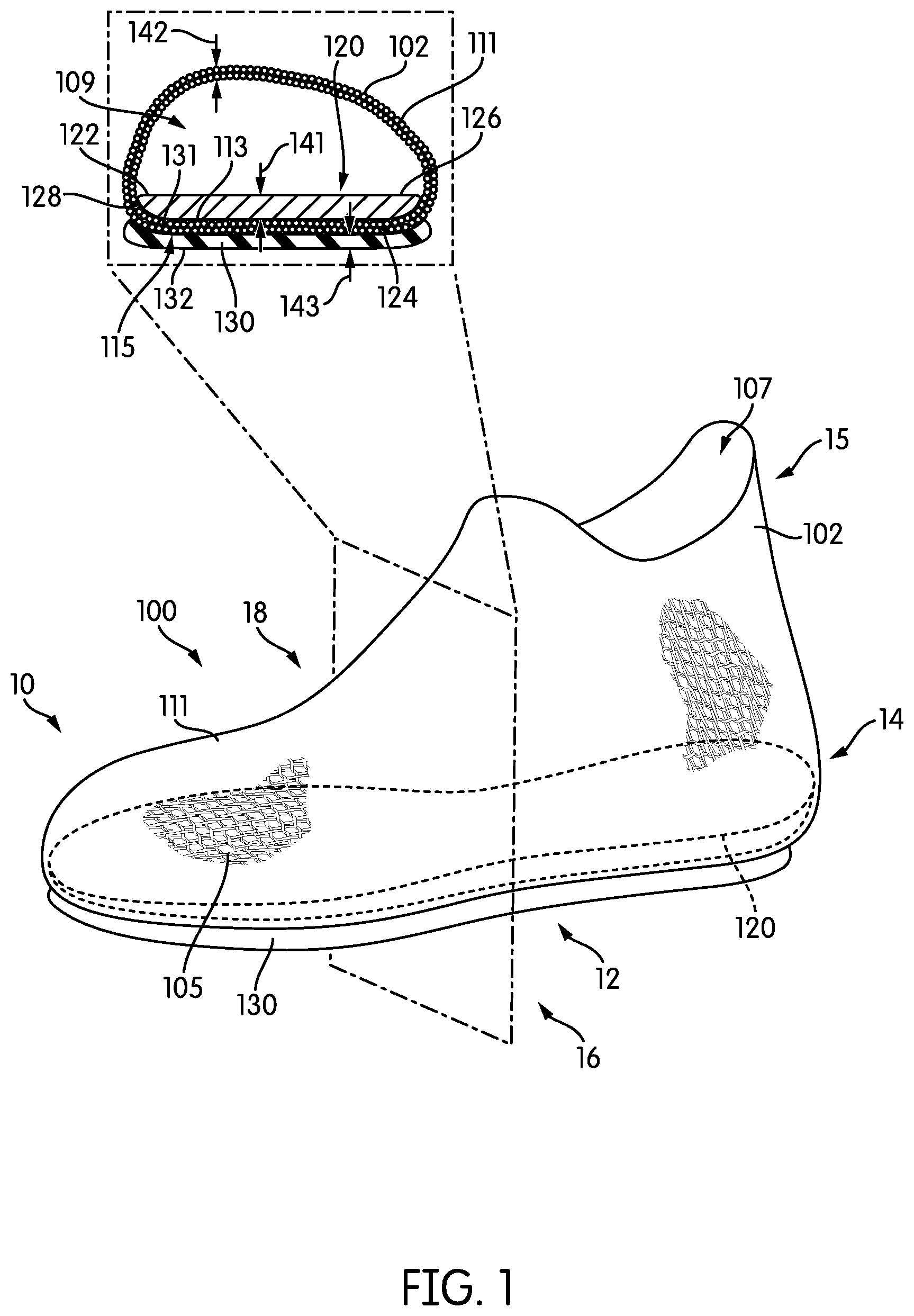
FIG. 1 is a schematic isometric view of an embodiment of an article of footwear including an enlarged cross-sectional view of a forefoot portion of the article of footwear;
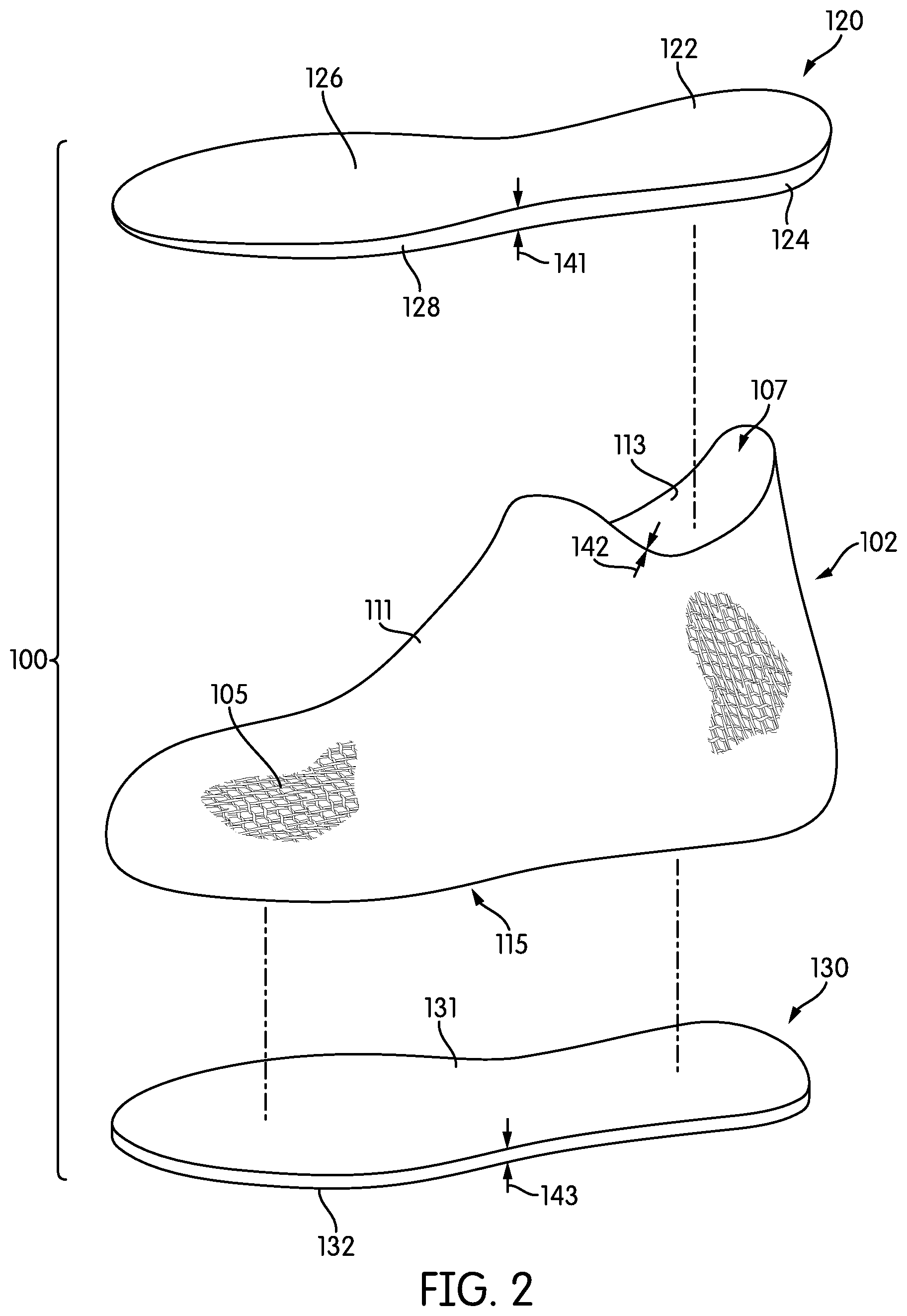
FIG. 2 is a schematic isometric exploded view of the article of footwear of FIG. 1;
FIG. 3 is a schematic view of the article of FIG. 1 with a foot inserted within an upper, including an enlarged cross-sectional view of a forefoot portion of the article of footwear and foot;
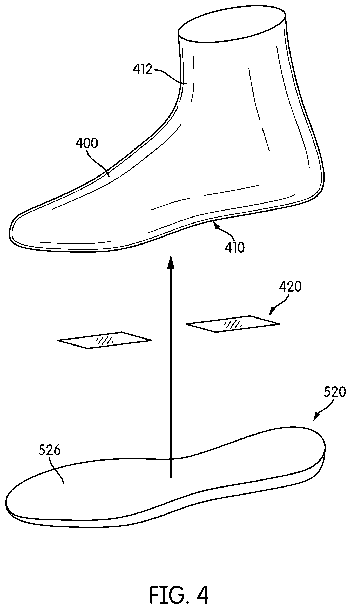
FIG. 4 is a schematic isometric view of a step of temporarily attaching a midsole structure to a last, according to an embodiment;
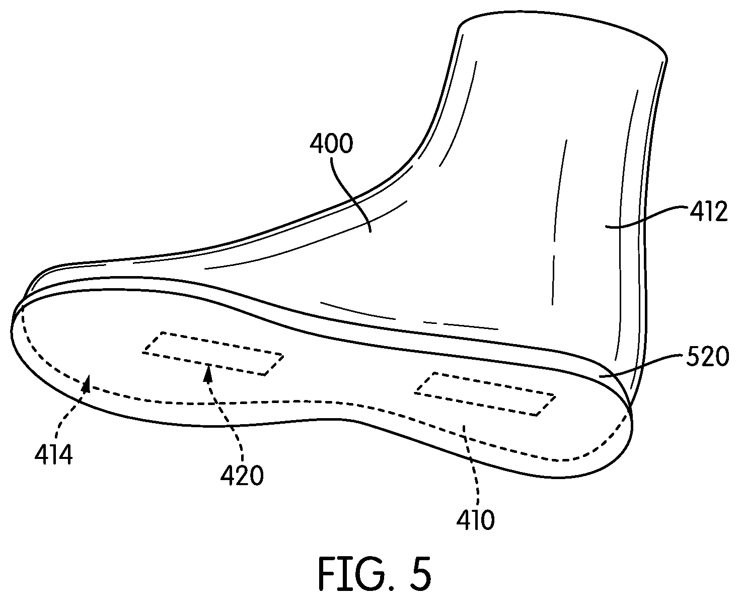
FIG. 5 is a schematic bottom isometric view of an embodiment of a midsole structure temporarily attached to a last;
FIG. 6 is a schematic isometric view of the last and midsole structure of FIG. 5, including an enlarged cross-sectional view of the last and midsole structure;
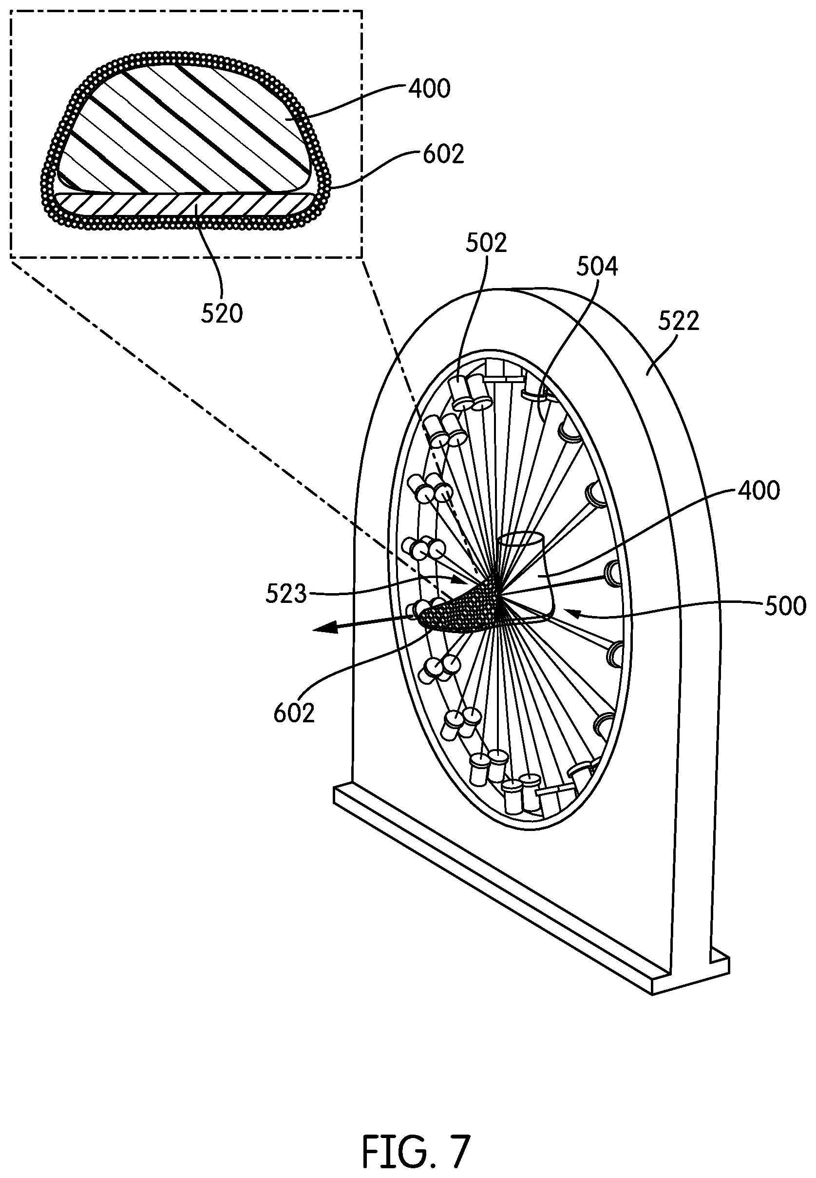
FIG. 7 is a schematic isometric view of an embodiment of a last and midsole structure inserted through a braiding device to form a braided structure over the last and midsole structure;
FIG. 8 is a schematic isometric view of a braided upper being cut to form an opening according to an embodiment;
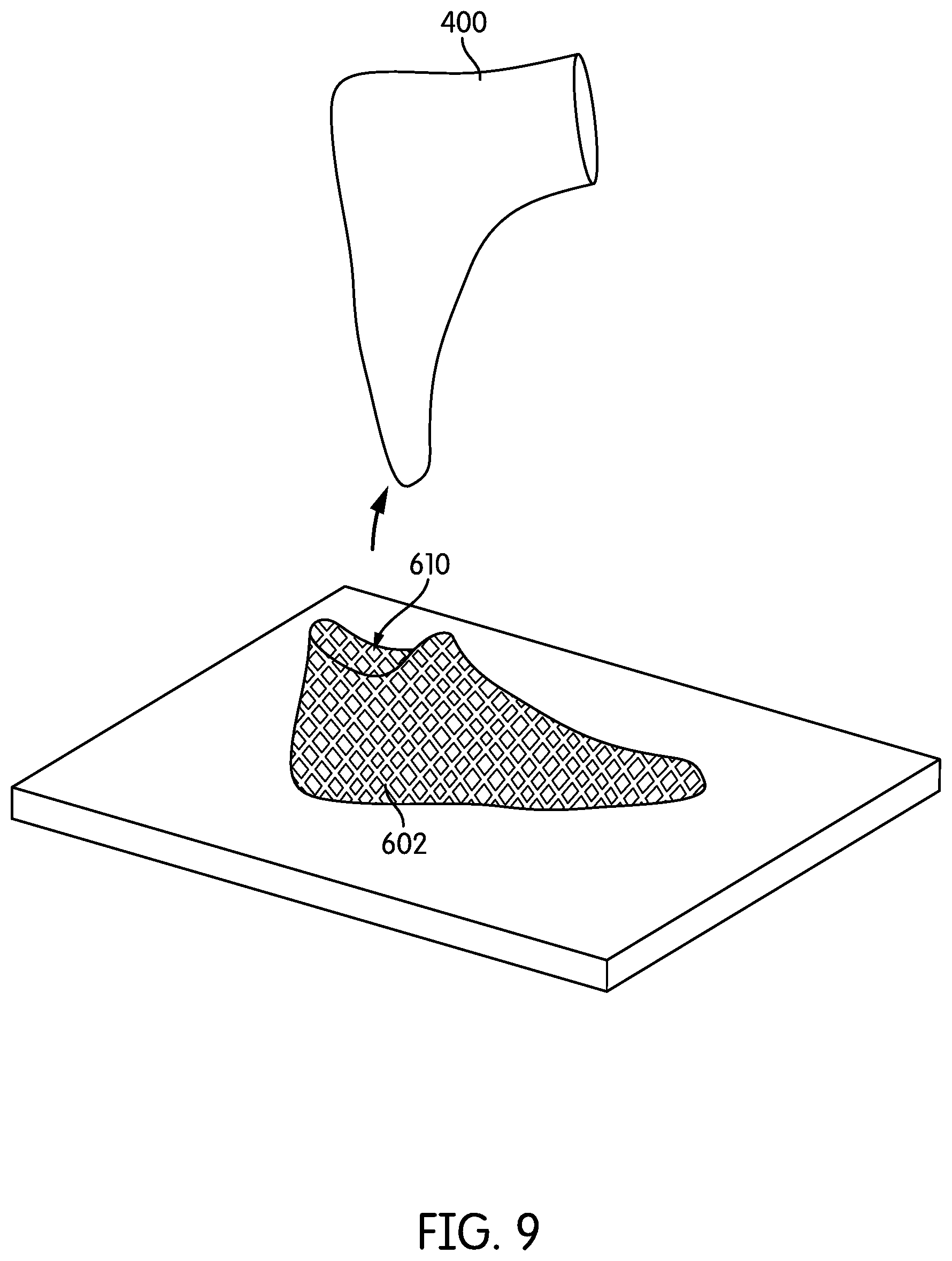
FIG. 9 is a schematic view of a last being removed from a braided upper according to an embodiment;
FIG. 10 is a schematic view of an outer sole structure being attached to a lower surface of a braided upper according to an embodiment;
FIG. 11 is a schematic view of an embodiment of an upper with an interior midsole structure;
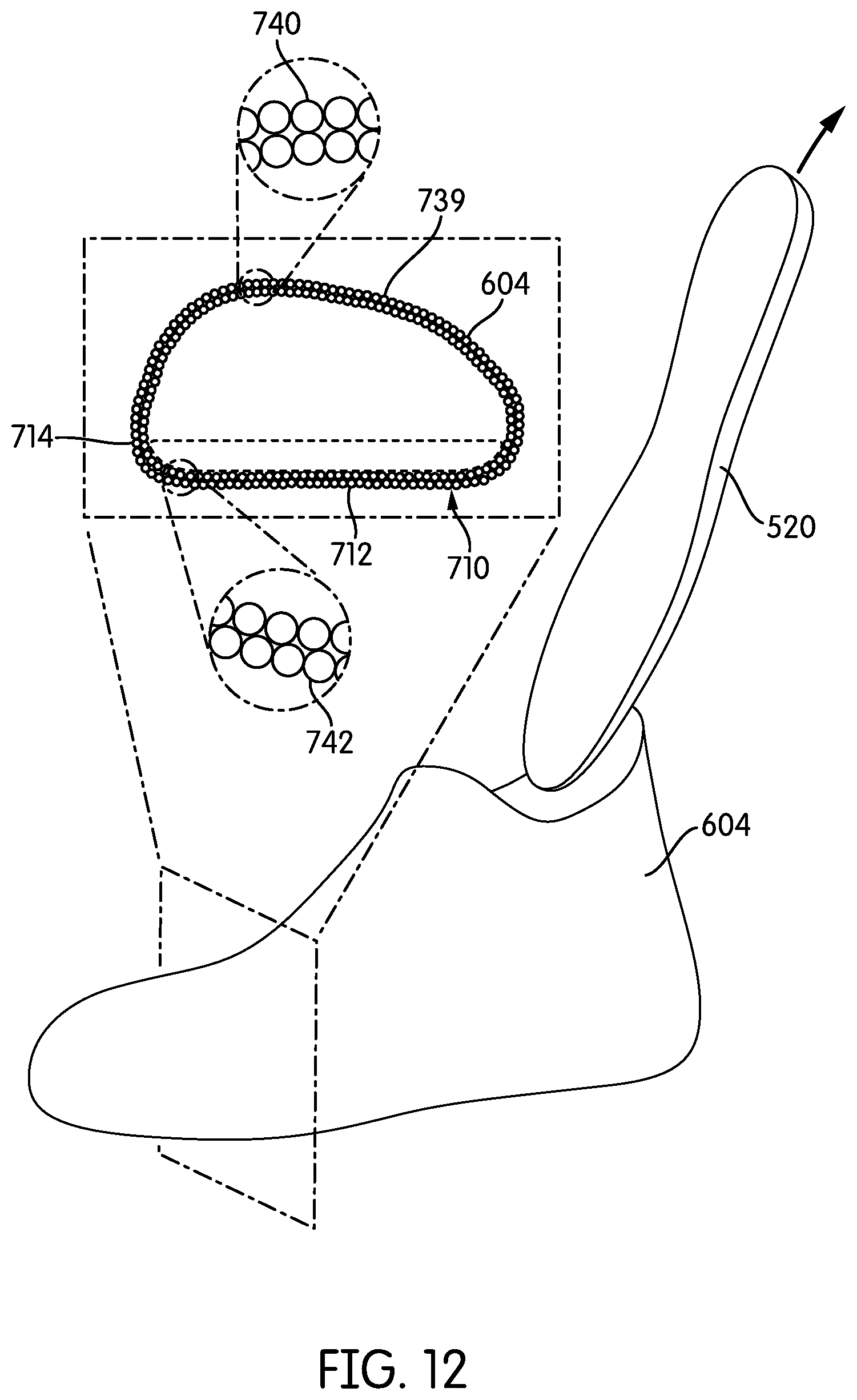
FIG. 12 is a schematic view of the upper of FIG. 11 with the midsole structure removed;
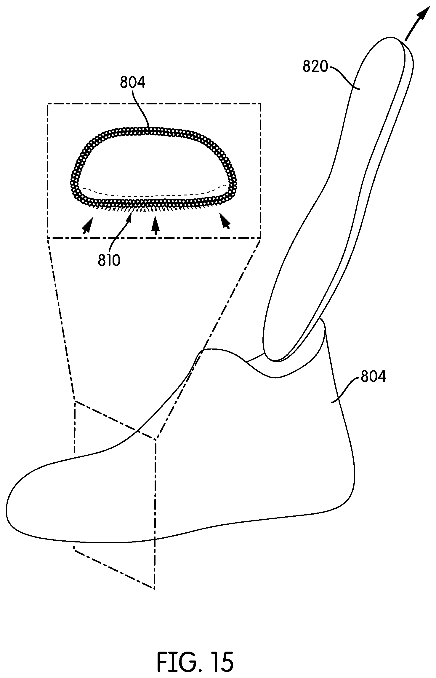
FIGS. 13-15 illustrate schematic views of an alternative embodiment of an upper formed from a braided structure, where the upper is formed on a last and a midsole structure is inserted after the upper is formed on the last.
DETAILED DESCRIPTION
FIG. 1 is an isometric view of an embodiment of an article of footwear 100. In the exemplary embodiment, article of footwear 100 has the form of an athletic shoe. However, in other embodiments, the provisions discussed herein for article of footwear 100 could be incorporated into various other kinds of footwear including, but not limited to: basketball shoes, hiking boots, soccer shoes, football shoes, sneakers, running shoes, cross-training shoes, rugby shoes, baseball shoes as well as other kinds of shoes. Moreover, in some embodiments, the provisions discussed herein for article of footwear 100 could be incorporated into various other kinds of non-sports related footwear, including, but not limited to: slippers, sandals, high heeled footwear, and loafers.
For purposes of clarity, the following detailed description discusses the features of article of footwear 100, also referred to simply as article 100. However, it will be understood that other embodiments may incorporate a corresponding article of footwear (e.g., a right article of footwear when article 100 is a left article of footwear) that may share some, and possibly all, of the features of article 100 described herein and shown in the figures.
The embodiments may be characterized by various directional adjectives and reference portions. These directions and reference portions may facilitate in describing the portions of an article of footwear. Moreover, these directions and reference portions may also be used in describing sub-components of an article of footwear (e.g., directions and/or portions of a midsole structure, an outer sole structure, an upper or any other components).
For consistency and convenience, directional adjectives are employed throughout this detailed description corresponding to the illustrated embodiments. The term "longitudinal" as used throughout this detailed description and in the claims refers to a direction extending a length of a component (e.g., an upper or sole component). In some cases, the longitudinal direction may extend from a forefoot portion to a heel portion of the component. Also, the term "lateral" as used throughout this detailed description and in the claims refers to a direction extending along a width of a component. In other words, the lateral direction may extend between a medial side and a lateral side of a component. Furthermore, the term "vertical" as used throughout this detailed description and in the claims refers to a direction generally perpendicular to a lateral and longitudinal direction. For example, in cases where an article is planted flat on a ground surface, the vertical direction may extend from the ground surface upward. Additionally, the term "inner" refers to a portion of an article disposed closer to an interior of an article, or closer to a foot when the article is worn. Likewise, the term "outer" refers to a portion of an article disposed further from the interior of the article or from the foot. Thus, for example, the inner surface of a component is disposed closer to an interior of the article than the outer surface of the component. This detailed description makes use of these directional adjectives in describing an article and various components of the article, including an upper, a midsole structure and/or an outer sole structure.
Article 100 may be characterized by a number of different regions or portions. For example, article 100 could include a forefoot portion, a midfoot portion, a heel portion and an ankle portion. Moreover, components of article 100 could likewise comprise corresponding portions. Referring to FIG. 1, article 100 may be divided into forefoot portion 10, midfoot portion 12 and heel portion 14. Forefoot portion 10 may be generally associated with the toes and joints connecting the metatarsals with the phalanges. Midfoot portion 12 may be generally associated with the arch of a foot. Likewise, heel portion 14 may be generally associated with the heel of a foot, including the calcaneus bone. Article 100 may also include an ankle portion 15 (which may also be referred to as a cuff portion). In addition, article 100 may include lateral side 16 and medial side 18. In particular, lateral side 16 and medial side 18 may be opposing sides of article 100. Furthermore, both lateral side 16 and medial side 18 may extend through forefoot portion 10, midfoot portion 12, heel portion 14 and ankle portion 15.
FIGS. 1-2 illustrate various components of article of footwear 100, including an upper 102, a midsole structure 120 and an outer sole structure 130. For purposes of illustration, in FIG. 1, midsole structure 120 is shown in phantom in the isometric view of article 100.
Upper 102 may be a braided upper. More specifically, upper 102 may comprise a braided structure having the form of an upper for an article of footwear. As used herein, the term "braided structure" (or braided component) refers to any structure that may be formed by intertwining three or more tensile elements to form the structure. Such tensile elements could include, but are not limited to: threads, yarns, strings, filaments, fibers, wires, cables as well as possibly other kinds of tensile elements. As used herein, tensile elements may describe generally elongated materials with lengths much greater than corresponding diameters. In other words, tensile elements may be approximately one-dimensional elements, in contrast to sheets or layers of textile materials that may generally be approximately two-dimensional (e.g., with thicknesses much less than their lengths and widths). As an example, upper 102 as seen in FIGS. 1-2 is formed from a plurality of tensile elements 105 (e.g., yarns or strands of material) that are braided together to form a shape that is globally similar to the shape of a foot. For purposes of illustration, the individual tensile elements 105 are only shown in representative patches on upper 102 in the figures, but it may be understood that in at least some embodiments the entirety of upper 102 may comprise tensile elements 105 in a braided configuration.
Braiding can be used to form three-dimensional structures, by braiding strands of yarn over a form or a last. Strands of a braided structure, such as plurality of tensile elements 105 of the exemplary embodiment, can be fabricated from fibers such as nylon, carbon, polyurethane, polyester, cotton, aramid (e.g., Kevlar.RTM.), polyethylene or polypropylene. These strands can be braided to form three-dimensional structures for a wide variety of applications.
Braided structures may be fabricated manually, or may be manufactured using automated braiding machinery, such as the machinery disclosed in U.S. Pat. Nos. 7,252,028; 8,261,648; 5,361,674; 5,398,586; and 4,275,638, all of which are incorporated by reference in their entirety herein. One exemplary manufacturing method, including the use of a radial braiding machine, is discussed below and shown in FIG. 7.
Some embodiments may include braided uppers that extend beneath the foot, thereby providing 360 degree coverage at some regions of the foot. However, other embodiments need not include uppers that extend beneath the foot. In other embodiments, for example, a braided upper could have a lower periphery joined with a sole structure and/or sock liner. In the exemplary embodiment, upper 102 includes a closed lower portion 115 (see FIGS. 1-3) that extends beneath a foot when the article is worn.
Embodiments could incorporate any of the braided structures, methods of making braided structure as well as any of the related provisions that are disclosed in U.S. patent application Ser. No. 14/495,252 filed Sep. 24, 2014, published as U.S. Publication Number 2015/0007451, and titled "Article of Footwear with Braided Upper," the entirety of which is herein incorporated by reference and hereafter referred to as "the Braided Upper application".
Referring to FIGS. 1-2, upper 102 is seen to have an opening 107 that may receive a foot. Opening 107 may provide access to an interior cavity 109 of upper 102. In the exemplary embodiment, upper 102 may have a bootie-like configuration without any additional fasteners. Depending on the material of the individual tensile strands 105, the exemplary embodiment may be configured to stretch fit over a foot without the need for additional fasteners. For example, using tensile strands 105 with elastic properties may allow upper 102 to stretch over a foot and provide the needed amount of tension to keep article 100 on the foot. However, in other embodiments, upper 102 could incorporate fastening provisions including laces, straps, zippers or other kinds of fasteners that may help secure upper 102 around a foot. For example, other embodiments could utilize any of the fastening provisions for a braided upper that are disclosed in the Braided Upper application.
Upper 102 may also be characterized by an outer surface 111, which is an exterior or exposed surface. In addition, upper 102 may include an inner surface 113 that is opposite outer surface 111.
Midsole structure 120 may generally incorporate various provisions associated with midsoles. In different embodiments, a midsole structure may be configured to provide cushioning, shock absorption, energy return, support, as well as possibly other provisions.
Midsole structure 120 may comprise an exterior surface 122. Exterior surface 122 may be further comprised of a first surface 124 and a second surface 126 disposed opposite of first surface 124. Here, first surface 124 may be a lower surface of midsole structure 120, while second surface 126 may be an upper surface of midsole structure 120. Moreover, first surface 124 may include a first surface periphery 128 (e.g., a lower surface periphery), which extends around the boundary of first surface 124. In some cases, first surface periphery 128 may be associated with the sides (or sidewalls) of midsole structure 120. Second surface 126 may extend from first surface periphery 128 (i.e., second surface 126 is proximate to, or even continuous with, first surface periphery 128) and across the top side of midsole structure 120.
In different embodiments, the geometry of midsole structure 120 could vary. In some embodiments, midsole structure 120 may have a two-dimensional geometry (e.g., a geometry in the plane spanned by the longitudinal and lateral directions) corresponding to a foot sole. In other embodiments, however, the geometry of midsole structure 120 could vary and could include various contours or features not associated with a foot sole.
In different embodiments, the dimensions of midsole structure 120 could vary. In some embodiments, midsole structure 120 has a length approximately equal to a length of upper 102, as midsole structure 120 may extend through the entirety of interior cavity 109 in the longitudinal direction. In other embodiments, however midsole structure 120 could have a length less than the length of upper 102. For example, in another embodiment, a midsole structure may only extend through the midfoot and heel portions of an article of footwear. In some embodiments, midsole structure 120 has a width approximately equal to a width of upper 102, as midsole structure 120 may extend through the entire of interior cavity 109 in the lateral direction. However, in other embodiments, a midsole structure could only extend partially across the width of upper 102.
In some embodiments, the thickness of midsole structure 120 may vary. In some embodiments, a midsole structure could be thicker than either an upper or an outer sole structure. In other embodiments, a midsole structure could be thinner than an upper and/or an outer sole structure. In some cases, a midsole structure could be equal in thickness to an upper and/or a sole structure. In the exemplary embodiment, midsole structure 120 has a thickness 141 that corresponds to the distance between first surface 124 and second surface 126 of midsole structure 120. In addition, upper 102 has a thickness 142 and outer sole structure 130 has a thickness 143. Moreover, thickness 141 is greater than thickness 142. Also, thickness 141 is greater than thickness 143. This relatively greater thickness for midsole structure 120 may ensure that midsole structure 120 provides a larger degree of the shock absorption, cushioning and/or support than may be provided by the material structures of upper 102 and outer sole structure 130.
A midsole structure may be formed from a variety of different materials. Exemplary materials that could be used in various embodiments include, but are not limited to: expanded rubber, foam rubber, various kinds of foams, polyurethane as well as possibly other materials. For example, in one embodiment, a midsole structure may be formed from a polymer foam material that attenuates ground reaction forces (i.e., provides cushioning) during walking, running, and other ambulatory activities. In various embodiments, midsole structures may also include fluid-filled chambers, plates, moderators, or other elements that further attenuate forces, enhance stability, or influence the motions of the foot, for example.
Outer sole structure 130 may include provisions for cushioning and/or may include provisions to enhance ground contact. In some embodiments, outer sole structure 130 could primarily comprise an outsole. In such embodiments, the outsole forms a ground-contacting element of the footwear and is usually fashioned from a durable and wear-resistant rubber material that includes texturing to impart traction. In other embodiments, outer sole structure 130 could also include cushioning provisions, including provisions associated with a midsole layer.
In the embodiments of FIGS. 1-2, outer sole structure 130 may be characterized by a first surface 131 and a second surface 132 that is opposite of first surface 131. First surface 131 may face inwardly, or towards upper 102, while second surface 132 may face outwardly and may be a ground contacting surface. In some embodiments, second surface 132 could include provisions for enhancing traction with a ground surface such as treads, cleats, or other provisions.
As seen in FIGS. 1-2, midsole structure 120 may be disposed within upper 102. Specifically, midsole structure 120 may be disposed within interior cavity 109 of upper 102. In some cases, first surface 124 of midsole structure 120 (i.e., a lower surface) may be disposed against inner surface 113 of upper 102. In other cases, first surface 124 of midsole structure 120 could be disposed against an intermediate layer, or may be otherwise spaced apart from inner surface 113 of upper 102. In either case, midsole structure 120 may be disposed closer to inner surface 113 of lower portion 115 (of upper 102) than to outer surface 111 of lower portion 115. Such an arrangement may be contrasted with other possible embodiments, where a midsole structure may be disposed externally to an upper and therefore disposed closer to an outer surface of the upper than to the inner surface of the upper.
Outer sole structure 130 may be disposed against outer surface 111 of upper 102. More specifically, first surface 131 outer sole structure 130 may be disposed against outer surface 111 on lower portion 115 of upper 102. Thus, whereas midsole structure 120 may be disposed within interior cavity 109 of upper 102, outer sole structure 130 may be disposed outwardly on upper 102. Therefore, lower portion 115 of upper 102 may separate, or be disposed between, midsole structure 120 and outer sole structure 130.
For purposes of clarity, article 100 is shown without an inner liner or insole. In such an embodiment, a foot (or sock worn on the foot) may directly contact a surface of a midsole structure. For example, in some embodiments, second surface 126 of midsole structure 120 may be configured to receive and contact a foot directly. Such an exemplary configuration is shown in FIG. 3, which shows a schematic view of a foot 300 inserted within article of footwear 100 along with a cross-sectional view of the article and foot as taken along a vertical plane 304. In the configuration of FIG. 3, foot 300 directly contacts second surface 126 of midsole structure 120. In other embodiments, however, an optional insole or inner liner could be present between a foot and midsole structure 120 when article 100 is worn. Such a liner or insole may be disposed on second surface 126 of midsole structure 120.
Each component may be characterized by various material characteristics, including cushioning and compressibility. In various embodiments, the relative material characteristics of each component (e.g., upper 102, midsole structure 120 and outer sole structure 130) could be varied. In one exemplary embodiment, midsole structure 120 may provide greater cushioning than either upper 102 or outer sole structure 130. In addition, in one embodiment, midsole structure 120 may be more compressible than upper 102 and midsole structure 120 may be more compressible than outer sole structure 130.
The exemplary embodiment shown in FIG. 3 shows the relative compressibility of midsole structure 120 relative to upper 102 and outer sole structure 130. For example, midsole structure 120 is seen to compress under the weight of foot 300. Specifically, midsole structure 120 undergoes a change from an uncompressed thickness 320 to a compressed thickness 322. In contrast, upper 102 does not undergo any significant compression (e.g., change in thickness) at lower portion 115 under the weight of foot 300. Likewise, outer sole structure 130 does not undergo any significant compression under the weight of foot 300.
In different embodiments, the degree of relative compressibility between midsole structure 120 and other components of article 100 can vary. In at least some embodiments, midsole structure 120 can undergo changes in thickness due to compressive forces (e.g., weight of foot or other ground contact forces) that are greater than the thickness of upper 102. In other words, the change in thickness (e.g., between uncompressed thickness 320 and compressed thickness 322) could be greater than a thickness of upper 102 (e.g., thickness 142 as shown in FIG. 1). The degree of compression for a given force can vary according to factors including but not limited to: desired cushioning properties, midsole structure materials, midsole structure geometry as well as possibly other factors. Moreover, the compression of midsole structure 120 can be tuned to achieve optimal comfort and cushioning for a user.
In different embodiments, the attachment configurations of various components of article 100 could vary. For example, in some embodiments, midsole structure 120 could be bonded or otherwise attached to an inner surface of upper 102. Such bonding or attachment could be accomplished using any known methods for bonding components of articles of footwear, including, but not limited to: adhesives, films, tapes, staples, stitching, or other methods. In some other embodiments, it is contemplated that midsole structure 120 may not be bonded or attached to upper 102, and instead could be free-floating.
Outer sole structure 130 may be attached to upper 102 and/or midsole structure 120. In some embodiments, outer sole structure 130 could be attached directly to upper 102 using various attachment methods including, but not limited to: adhesives, tapes, staples, stitching, or other methods. In one embodiment, outer sole structure 130 and/or upper 102 could include one or more heat bonding materials (e.g., thermoplastics or other resins) that may act as a bonding layer between outer sole structure 130 and upper 102 when heated.
It is also contemplated that in at least some embodiments, outer sole structure 130 may be attached directly to midsole structure 120 through openings in the braided structure of upper 102 (e.g., through the spaces between strands). Thus, in at least some cases, an adhesive could be applied to first surface 131 of outer sole structure 130 to bond outer sole structure 130 to upper 102 and portions of midsole structure 120 simultaneously. In still other embodiments, outer sole structure 130 and/or midsole structure 120 could be made of heat bondable materials, so that after arranging outer sole structure 130 and midsole structure 120 relative to upper 102, heat may be applied to melt and bond outer sole structure 130 and midsole structure 120 to one another. In such cases, outer sole structure 130 and midsole structure 120 could be formed from bond compatible materials. Such an arrangement where outer sole structure 130 is attached directly to midsole structure 120 may help to anchor outer sole structure 130 to article 100.
In order to form a braided upper with an internal midsole structure, a midsole structure may first be temporarily attached to a last. The last with the temporarily attached midsole structure (also referred to collectively as a lasting assembly) may then be fed through a braiding device (such as a radial braiding machine) to form a braided structure in the form of a braided upper around the last and midsole structure. Upon removal of the last, a braided upper with an internal midsole structure may be assembled with an outer sole structure to form an article of footwear, similar to article 100 discussed above and shown in FIGS. 1-3.
FIGS. 4 and 5 illustrate schematic steps in a process of making an article of footwear, such as article 100, according to an embodiment. Specifically, FIG. 4 illustrates an exploded isometric view of a last 400 (i.e., a footwear last), adhesive film elements 420 and midsole structure 520. FIG. 5 illustrates a bottom isometric view of midsole structure 520 attached to last 400 using adhesive film elements 420. It will be understood that midsole structure 520 may be similar to midsole structure 120 of the embodiments shown in FIGS. 1-3, and may optionally include some or all of the provisions discussed with respect to midsole structure 120.
In FIGS. 4 and 5, a process of temporarily attaching midsole structure 120 to last 400 may be accomplished using adhesive film elements 420. In particular, second surface 526 of midsole structure 120 may be temporarily bonded to a lower surface 410 (i.e., a sole surface) of last 400 by inserting adhesive film elements 420 between second surface 126 and lower surface 410.
For purpose of clarity, only two film elements are shown, however in other embodiments any number, size, and arrangement of adhesive film elements could be used. In other embodiments, of course, any other method of temporarily fixing, attaching, bonding, adhering or otherwise temporarily joining a midsole structure with a last could be used. Exemplary methods include, but are not limited to, the use of adhesives, films, tapes, putties, as well as possibly other methods. It is contemplated that in some embodiments a last could be configured with a fastening element (such as a screw or other projection) and a midsole structure could be configured with provisions to receive the fastening element (such as a threaded hole to receive a screw). Thus, in some embodiments, a last and a midsole structure could be temporarily secured using some kind of mechanical fasteners, including, but not limited to: screws, bolts, hook and loop fasteners, clips, straps, as well as possibly other mechanical provisions. The method of temporarily joining a midsole structure and a last can be selected according to various factors including: last material and/or dimensions, midsole structure material and/or dimensions, as well as possibly other factors.
For purposes of understanding the arrangement of midsole structure 520 and last 400, last 400 may be characterized as comprising various different portions. For example, last 400 may include not only a lower surface 410 (i.e., the sole surface of last 400), but also an upper surface 412. As used herein, the term "upper surface" of a last refers to the area of the last surface that does not include lower surface 410, which is the surface of the last corresponding to the sole of a foot. Thus, upper surface 412 may generally include the medial side surface, the lateral side surface as well as the upper, forward and rearward surfaces of last 400. Upper surface 412 may generally extend to, or join, a lower surface periphery 414 of lower surface 410.
As seen in FIGS. 4 and 5, midsole structure 520, when temporarily attached to last 400, covers only lower surface 410 of last 400. In particular, upper surface 412 may be exposed when midsole structure 120 is temporarily attached to last 400. Such an arrangement may be in contrast, for example, to the placement of a bootie-like liner over last 400, which would tend to cover both lower surface 410 and upper surface 412. In other words, the exemplary configuration of a component applied to last 400 is one where the component (a midsole structure) is applied only to a local portion of last 400, namely the lower surface 410 of last 400, rather than being uniformly applied over last 400 as in the case of a liner or other intermediate layer.
In order to enhance the operation of a braiding device, such as a radial braiding machine, it may be important to use last assemblies having smooth geometries. For purposes of clarity in characterizing the smoothness of these geometries, the term peripheral contour is used herein to denote the contour or boundary of a given cross-sectional area of a component. Additionally, contours, or lines that bound a given cross-sectional area, can be characterized as having curvature that may vary over different sections of the contour. In the present discussion, the curvature of a given section of a contour may be described by a radius of curvature and the curvature of different sections can be compared according to the differences in their radii of curvature.
FIG. 6 illustrates an isometric view of lasting assembly 500, comprising last 400 and midsole structure 520, including an enlarged cross-sectional view of a portion of lasting assembly 500. In particular, a cross-sectional view of forefoot portion 430 of last 400 is shown taken along a plane 450. As seen in FIG. 6, forefoot portion 430 has a cross-sectional area 425 and a peripheral contour 427 that bounds the cross-sectional area 425. Peripheral contour 427 may further be comprised of a top portion 432, a bottom portion 434, a medial side portion 436 and a lateral side portion 438.
As shown in FIG. 6, medial side portion 436 and lateral side po
References
D00000
D00001
D00002
D00003
D00004
D00005
D00006
D00007
D00008
D00009
D00010
D00011
D00012
D00013

D00014

D00015
XML
uspto.report is an independent third-party trademark research tool that is not affiliated, endorsed, or sponsored by the United States Patent and Trademark Office (USPTO) or any other governmental organization. The information provided by uspto.report is based on publicly available data at the time of writing and is intended for informational purposes only.
While we strive to provide accurate and up-to-date information, we do not guarantee the accuracy, completeness, reliability, or suitability of the information displayed on this site. The use of this site is at your own risk. Any reliance you place on such information is therefore strictly at your own risk.
All official trademark data, including owner information, should be verified by visiting the official USPTO website at www.uspto.gov. This site is not intended to replace professional legal advice and should not be used as a substitute for consulting with a legal professional who is knowledgeable about trademark law.