Surgical staples, staple cartridges and surgical end effectors
Shelton, IV , et al.
U.S. patent number 10,588,624 [Application Number 15/472,655] was granted by the patent office on 2020-03-17 for surgical staples, staple cartridges and surgical end effectors. This patent grant is currently assigned to Ethicon LLC. The grantee listed for this patent is Ethicon LLC. Invention is credited to Chester O. Baxter, III, Jerome R. Morgan, Frederick E. Shelton, IV.


View All Diagrams
| United States Patent | 10,588,624 |
| Shelton, IV , et al. | March 17, 2020 |
Surgical staples, staple cartridges and surgical end effectors
Abstract
A surgical instrument assembly is disclosed. The surgical instrument assembly can include an instrument attachment interface, a shaft, a firing member, an articulation joint, and an end effector including a first jaw, a second jaw, an anvil, and a replaceable staple cartridge comprising a proximal end, a distal end, a slot, at least two rows of staple cavities, and a plurality of staples stored within the staple cavities. The staples can be deployed by the firing member. Each staple can include, one, a staple leg comprising planar surfaces and, two, a staple base, wherein the staple leg extends from the staple base, wherein the staple base comprises planar surfaces and a camming surface distally offset from the staple leg and configured to be directly engaged by the firing member, and wherein the staple leg is configured to be formed over the camming surface.
| Inventors: | Shelton, IV; Frederick E. (Hillsboro, OH), Baxter, III; Chester O. (Loveland, OH), Morgan; Jerome R. (Cincinnati, OH) | ||||||||||
|---|---|---|---|---|---|---|---|---|---|---|---|
| Applicant: |
|
||||||||||
| Assignee: | Ethicon LLC (Guaynabo,
PR) |
||||||||||
| Family ID: | 62186013 | ||||||||||
| Appl. No.: | 15/472,655 | ||||||||||
| Filed: | March 29, 2017 |
Prior Publication Data
| Document Identifier | Publication Date | |
|---|---|---|
| US 20170245857 A1 | Aug 31, 2017 | |
Related U.S. Patent Documents
| Application Number | Filing Date | Patent Number | Issue Date | ||
|---|---|---|---|---|---|
| 14138489 | Dec 23, 2013 | 9687232 | |||
| Current U.S. Class: | 1/1 |
| Current CPC Class: | A61B 34/37 (20160201); A61B 17/0682 (20130101); A61B 17/105 (20130101); A61B 17/068 (20130101); A61B 17/0644 (20130101); A61B 17/072 (20130101); A61B 17/07207 (20130101); A61B 2017/07285 (20130101); A61B 17/0686 (20130101); A61B 2017/07271 (20130101); A61B 2017/07278 (20130101); A61B 2017/07257 (20130101); A61B 2017/07228 (20130101); Y10T 29/49995 (20150115); A61B 17/064 (20130101); A61B 2017/00734 (20130101); A61B 2017/00526 (20130101); A61B 2017/00398 (20130101) |
| Current International Class: | A61B 17/064 (20060101); A61B 17/072 (20060101); A61B 17/10 (20060101); A61B 34/37 (20160101); A61B 17/068 (20060101); A61B 17/00 (20060101) |
References Cited [Referenced By]
U.S. Patent Documents
| 66052 | June 1867 | Smith |
| 662587 | November 1900 | Blake |
| 670748 | March 1901 | Weddeler |
| 951393 | March 1910 | Hahn |
| 1306107 | June 1919 | Elliott |
| 1314601 | September 1919 | McCaskey |
| 1677337 | July 1928 | Grove |
| 1794907 | March 1931 | Kelly |
| 2037727 | April 1936 | La Chapelle |
| 2132295 | October 1938 | Hawkins |
| 2161632 | June 1939 | Nattenheimer |
| 2211117 | August 1940 | Hess |
| 2214870 | September 1940 | West |
| 2318379 | May 1943 | Davis et al. |
| 2441096 | May 1948 | Happe |
| 2475322 | July 1949 | Horton et al. |
| 2526902 | October 1950 | Rublee |
| 2578686 | December 1951 | Fish |
| 2674149 | April 1954 | Benson |
| 2711461 | June 1955 | Happe |
| 2804848 | September 1957 | O'Farrell et al. |
| 2808482 | October 1957 | Zanichkowsky et al. |
| 2853074 | September 1958 | Olson |
| 2886358 | May 1959 | Munchbach |
| 2959974 | November 1960 | Emrick |
| 3032769 | May 1962 | Palmer |
| 3060972 | October 1962 | Sheldon |
| 3075062 | January 1963 | Iaccarino |
| 3078465 | February 1963 | Bobrov |
| 3079606 | March 1963 | Bobrov et al. |
| 3166072 | January 1965 | Sullivan, Jr. |
| 3196869 | July 1965 | Scholl |
| 3204731 | September 1965 | Bent et al. |
| 3266494 | August 1966 | Brownrigg et al. |
| 3269630 | August 1966 | Fleischer |
| 3275211 | September 1966 | Hirsch et al. |
| 3317103 | May 1967 | Cullen et al. |
| 3499591 | March 1970 | Green |
| 3551987 | January 1971 | Wilkinson |
| 3583393 | June 1971 | Takahashi |
| 3662939 | May 1972 | Bryan |
| 3717294 | February 1973 | Green |
| 3799151 | March 1974 | Fukaumi et al. |
| 3940844 | March 1976 | Colby et al. |
| RE28932 | August 1976 | Noiles et al. |
| 4014244 | March 1977 | Larson |
| 4060089 | November 1977 | Noiles |
| 4106446 | August 1978 | Yamada et al. |
| 4108211 | August 1978 | Tanaka |
| 4111206 | September 1978 | Vishnevsky et al. |
| 4129059 | December 1978 | Van Eck |
| 4169990 | October 1979 | Lerdman |
| 4180285 | December 1979 | Reneau |
| 4198734 | April 1980 | Brumlik |
| 4198982 | April 1980 | Fortner et al. |
| 4207898 | June 1980 | Becht |
| 4213562 | July 1980 | Garrett et al. |
| 4226242 | October 1980 | Jarvik |
| 4241861 | December 1980 | Fleischer |
| 4244372 | January 1981 | Kapitanov et al. |
| 4250436 | February 1981 | Weissman |
| 4261244 | April 1981 | Becht et al. |
| 4272002 | June 1981 | Moshofsky |
| 4272662 | June 1981 | Simpson |
| 4274304 | June 1981 | Curtiss |
| 4275813 | June 1981 | Noiles |
| 4289133 | September 1981 | Rothfuss |
| 4296654 | October 1981 | Mercer |
| 4304236 | December 1981 | Conta et al. |
| 4305539 | December 1981 | Korolkov et al. |
| 4312685 | January 1982 | Riedl |
| 4317451 | March 1982 | Cerwin et al. |
| 4319576 | March 1982 | Rothfuss |
| 4321002 | March 1982 | Froehlich |
| 4328839 | May 1982 | Lyons et al. |
| 4331277 | May 1982 | Green |
| 4340331 | July 1982 | Savino |
| 4347450 | August 1982 | Colligan |
| 4349028 | September 1982 | Green |
| 4353371 | October 1982 | Cosman |
| 4379457 | April 1983 | Gravener et al. |
| 4380312 | April 1983 | Landrus |
| 4382326 | May 1983 | Rabuse |
| 4383634 | May 1983 | Green |
| 4393728 | July 1983 | Larson et al. |
| 4396139 | August 1983 | Hall et al. |
| 4397311 | August 1983 | Kanshin et al. |
| 4402445 | September 1983 | Green |
| 4408692 | October 1983 | Sigel et al. |
| 4409057 | October 1983 | Molenda et al. |
| 4415112 | November 1983 | Green |
| 4416276 | November 1983 | Newton et al. |
| 4428376 | January 1984 | Mericle |
| 4429695 | February 1984 | Green |
| 4434796 | March 1984 | Karapetian et al. |
| 4438659 | March 1984 | Desplats |
| 4442964 | April 1984 | Becht |
| 4448194 | May 1984 | DiGiovanni et al. |
| 4451743 | May 1984 | Suzuki et al. |
| 4454887 | June 1984 | Kruger |
| 4467805 | August 1984 | Fukuda |
| 4473077 | September 1984 | Noiles et al. |
| 4475679 | October 1984 | Fleury, Jr. |
| 4485816 | December 1984 | Krumme |
| 4486928 | December 1984 | Tucker et al. |
| 4488523 | December 1984 | Shichman |
| 4489875 | December 1984 | Crawford et al. |
| 4499895 | February 1985 | Takayama |
| 4500024 | February 1985 | DiGiovanni et al. |
| 4505272 | March 1985 | Utyamyshev et al. |
| 4505273 | March 1985 | Braun et al. |
| 4505414 | March 1985 | Filipi |
| 4506671 | March 1985 | Green |
| 4520817 | June 1985 | Green |
| 4522327 | June 1985 | Korthoff et al. |
| 4526174 | July 1985 | Froehlich |
| 4527724 | July 1985 | Chow et al. |
| 4530453 | July 1985 | Green |
| 4531522 | July 1985 | Bedi et al. |
| 4532927 | August 1985 | Miksza, Jr. |
| 4548202 | October 1985 | Duncan |
| 4565109 | January 1986 | Tsay |
| 4565189 | January 1986 | Mabuchi |
| 4566620 | January 1986 | Green et al. |
| 4569469 | February 1986 | Mongeon et al. |
| 4571213 | February 1986 | Ishimoto |
| 4573468 | March 1986 | Conta et al. |
| 4573469 | March 1986 | Golden et al. |
| 4573622 | March 1986 | Green et al. |
| 4576167 | March 1986 | Noiles |
| 4580712 | April 1986 | Green |
| 4585153 | April 1986 | Failla et al. |
| 4589416 | May 1986 | Green |
| 4591085 | May 1986 | Di Giovanni |
| 4597753 | July 1986 | Turley |
| 4600037 | July 1986 | Hatten |
| 4604786 | August 1986 | Howie, Jr. |
| 4605001 | August 1986 | Rothfuss et al. |
| 4605004 | August 1986 | Di Giovanni et al. |
| 4606343 | August 1986 | Conta et al. |
| 4607638 | August 1986 | Crainich |
| 4608981 | September 1986 | Rothfuss et al. |
| 4610250 | September 1986 | Green |
| 4610383 | September 1986 | Rothfuss et al. |
| 4612933 | September 1986 | Brinkerhoff et al. |
| D286180 | October 1986 | Korthoff |
| D286441 | October 1986 | Korthoff et al. |
| D286442 | October 1986 | Korthoff et al. |
| 4619262 | October 1986 | Taylor |
| 4619391 | October 1986 | Sharkany et al. |
| 4628459 | December 1986 | Shinohara et al. |
| 4629107 | December 1986 | Fedotov et al. |
| 4632290 | December 1986 | Green et al. |
| 4633874 | January 1987 | Chow et al. |
| 4634419 | January 1987 | Kreizman et al. |
| 4641076 | February 1987 | Linden |
| 4643731 | February 1987 | Eckenhoff |
| 4646722 | March 1987 | Silverstein et al. |
| 4652820 | March 1987 | Maresca |
| 4655222 | April 1987 | Florez et al. |
| 4662555 | May 1987 | Thornton |
| 4663874 | May 1987 | Sano et al. |
| 4664305 | May 1987 | Blake, III et al. |
| 4665916 | May 1987 | Green |
| 4667674 | May 1987 | Korthoff et al. |
| 4669647 | June 1987 | Storace |
| 4671445 | June 1987 | Barker et al. |
| 4676245 | June 1987 | Fukuda |
| 4684051 | August 1987 | Akopov et al. |
| 4693248 | September 1987 | Failla |
| 4700703 | October 1987 | Resnick et al. |
| 4708141 | November 1987 | Inoue et al. |
| 4709120 | November 1987 | Pearson |
| 4715520 | December 1987 | Roehr, Jr. et al. |
| 4719917 | January 1988 | Barrows et al. |
| 4727308 | February 1988 | Huljak et al. |
| 4728020 | March 1988 | Green et al. |
| 4728876 | March 1988 | Mongeon et al. |
| 4729260 | March 1988 | Dudden |
| 4730726 | March 1988 | Holzwarth |
| 4741336 | May 1988 | Failla et al. |
| 4743214 | May 1988 | Tai-Cheng |
| 4747820 | May 1988 | Hornlein et al. |
| 4750902 | June 1988 | Wuchinich et al. |
| 4752024 | June 1988 | Green et al. |
| 4754909 | July 1988 | Barker et al. |
| 4767044 | August 1988 | Green |
| D297764 | September 1988 | Hunt et al. |
| 4773420 | September 1988 | Green |
| 4777780 | October 1988 | Holzwarth |
| 4781186 | November 1988 | Simpson et al. |
| 4787387 | November 1988 | Burbank, III et al. |
| 4790225 | December 1988 | Moody et al. |
| 4802478 | February 1989 | Powell |
| 4805617 | February 1989 | Bedi et al. |
| 4805823 | February 1989 | Rothfuss |
| 4809695 | March 1989 | Gwathmey et al. |
| 4815460 | March 1989 | Porat et al. |
| 4817847 | April 1989 | Redtenbacher et al. |
| 4819853 | April 1989 | Green |
| 4821939 | April 1989 | Green |
| 4827911 | May 1989 | Broadwin et al. |
| 4830855 | May 1989 | Stewart |
| 4834720 | May 1989 | Blinkhorn |
| 4844068 | July 1989 | Arata et al. |
| 4848637 | July 1989 | Pruitt |
| 4865030 | September 1989 | Polyak |
| 4869414 | September 1989 | Green et al. |
| 4869415 | September 1989 | Fox |
| 4873977 | October 1989 | Avant et al. |
| 4874122 | October 1989 | Froelich et al. |
| 4880015 | November 1989 | Nierman |
| 4887601 | December 1989 | Richards |
| 4890613 | January 1990 | Golden et al. |
| 4892244 | January 1990 | Fox et al. |
| 4893622 | January 1990 | Green et al. |
| 4894051 | January 1990 | Shiber |
| 4896678 | January 1990 | Ogawa |
| 4900303 | February 1990 | Lemelson |
| 4903697 | February 1990 | Resnick et al. |
| 4915100 | April 1990 | Green |
| 4930503 | June 1990 | Pruitt |
| 4930674 | June 1990 | Barak |
| 4931047 | June 1990 | Broadwin et al. |
| 4932960 | June 1990 | Green et al. |
| 4938408 | July 1990 | Bedi et al. |
| 4941623 | July 1990 | Pruitt |
| 4944443 | July 1990 | Oddsen et al. |
| 4951860 | August 1990 | Peters et al. |
| 4955898 | September 1990 | Matsutani et al. |
| 4955959 | September 1990 | Tompkins et al. |
| 4965709 | October 1990 | Ngo |
| 4973274 | November 1990 | Hirukawa |
| 4978049 | December 1990 | Green |
| 4978333 | December 1990 | Broadwin et al. |
| 4986808 | January 1991 | Broadwin et al. |
| 4988334 | January 1991 | Hornlein et al. |
| 5002543 | March 1991 | Bradshaw et al. |
| 5002553 | March 1991 | Shiber |
| 5005754 | April 1991 | Van Overloop |
| 5009661 | April 1991 | Michelson |
| 5014899 | May 1991 | Presty et al. |
| 5015227 | May 1991 | Broadwin et al. |
| 5018515 | May 1991 | Gilman |
| 5018657 | May 1991 | Pedlick et al. |
| 5024671 | June 1991 | Tu et al. |
| 5027834 | July 1991 | Pruitt |
| 5031814 | July 1991 | Tompkins et al. |
| 5035040 | July 1991 | Kerrigan et al. |
| 5038109 | August 1991 | Goble et al. |
| 5040715 | August 1991 | Green et al. |
| 5042707 | August 1991 | Taheri |
| 5053047 | October 1991 | Yoon |
| 5061269 | October 1991 | Muller |
| 5062563 | November 1991 | Green et al. |
| 5065929 | November 1991 | Schulze et al. |
| 5071052 | December 1991 | Rodak et al. |
| 5071430 | December 1991 | de Salis et al. |
| 5074454 | December 1991 | Peters |
| 5079006 | January 1992 | Urquhart |
| 5080556 | January 1992 | Carreno |
| 5083695 | January 1992 | Foslien et al. |
| 5084057 | January 1992 | Green et al. |
| 5088979 | February 1992 | Filipi et al. |
| 5088997 | February 1992 | Delahuerga et al. |
| 5089009 | February 1992 | Green |
| 5094247 | March 1992 | Hernandez et al. |
| 5100420 | March 1992 | Green et al. |
| 5104025 | April 1992 | Main et al. |
| 5104397 | April 1992 | Vasconcelos et al. |
| 5106008 | April 1992 | Tompkins et al. |
| 5108368 | April 1992 | Hammerslag et al. |
| 5111987 | May 1992 | Moeinzadeh et al. |
| 5116349 | May 1992 | Aranyi |
| D327323 | June 1992 | Hunt |
| 5122156 | June 1992 | Granger et al. |
| 5125876 | June 1992 | Hirota |
| 5129570 | July 1992 | Schulze et al. |
| 5137198 | August 1992 | Nobis et al. |
| 5139513 | August 1992 | Segato |
| 5141144 | August 1992 | Foslien et al. |
| 5142932 | September 1992 | Moya et al. |
| 5155941 | October 1992 | Takahashi et al. |
| 5156315 | October 1992 | Green et al. |
| 5156609 | October 1992 | Nakao et al. |
| 5156614 | October 1992 | Green et al. |
| 5158567 | October 1992 | Green |
| D330699 | November 1992 | Gill |
| 5163598 | November 1992 | Peters et al. |
| 5170925 | December 1992 | Madden et al. |
| 5171247 | December 1992 | Hughett et al. |
| 5171249 | December 1992 | Stefanchik et al. |
| 5171253 | December 1992 | Klieman |
| 5188111 | February 1993 | Yates et al. |
| 5190517 | March 1993 | Zieve et al. |
| 5190544 | March 1993 | Chapman et al. |
| 5190560 | March 1993 | Woods et al. |
| 5192288 | March 1993 | Thompson et al. |
| 5195968 | March 1993 | Lundquist et al. |
| 5197648 | March 1993 | Gingold |
| 5197649 | March 1993 | Bessler et al. |
| 5197966 | March 1993 | Sommerkamp |
| 5200280 | April 1993 | Karasa |
| 5201746 | April 1993 | Shichman |
| 5205459 | April 1993 | Brinkerhoff et al. |
| 5207697 | May 1993 | Carusillo et al. |
| 5209747 | May 1993 | Knoepfler |
| 5211649 | May 1993 | Kohler et al. |
| 5211655 | May 1993 | Hasson |
| 5217457 | June 1993 | Delahuerga et al. |
| 5217478 | June 1993 | Rexroth |
| 5219111 | June 1993 | Bilotti et al. |
| 5221036 | June 1993 | Takase |
| 5221281 | June 1993 | Klicek |
| 5222963 | June 1993 | Brinkerhoff et al. |
| 5222975 | June 1993 | Crainich |
| 5222976 | June 1993 | Yoon |
| 5223675 | June 1993 | Taft |
| D338729 | August 1993 | Sprecklemeier et al. |
| 5234447 | August 1993 | Kaster et al. |
| 5236440 | August 1993 | Hlavacek |
| 5239981 | August 1993 | Anapliotis |
| 5240163 | August 1993 | Stein et al. |
| 5242457 | September 1993 | Akopov et al. |
| 5244462 | September 1993 | Delahuerga et al. |
| 5246156 | September 1993 | Rothfuss et al. |
| 5246443 | September 1993 | Mai |
| 5253793 | October 1993 | Green et al. |
| 5258009 | November 1993 | Conners |
| 5258012 | November 1993 | Luscombe et al. |
| 5259366 | November 1993 | Reydel et al. |
| 5260637 | November 1993 | Pizzi |
| 5263629 | November 1993 | Trumbull et al. |
| 5263973 | November 1993 | Cook |
| 5264218 | November 1993 | Rogozinski |
| 5268622 | December 1993 | Philipp |
| 5271543 | December 1993 | Grant et al. |
| 5271544 | December 1993 | Fox et al. |
| RE34519 | January 1994 | Fox et al. |
| 5275323 | January 1994 | Schulze et al. |
| 5275608 | January 1994 | Forman et al. |
| 5279416 | January 1994 | Malec et al. |
| 5281216 | January 1994 | Klicek |
| 5282806 | February 1994 | Haber et al. |
| 5282829 | February 1994 | Hermes |
| 5284128 | February 1994 | Hart |
| 5285945 | February 1994 | Brinkerhoff et al. |
| 5289963 | March 1994 | McGarry et al. |
| 5290271 | March 1994 | Jernberg |
| 5292053 | March 1994 | Bilotti et al. |
| 5297714 | March 1994 | Kramer |
| 5303539 | April 1994 | Neamtu |
| 5304204 | April 1994 | Bregen |
| D347474 | May 1994 | Olson |
| 5307976 | May 1994 | Olson et al. |
| 5308576 | May 1994 | Green et al. |
| 5309927 | May 1994 | Welch |
| 5312023 | May 1994 | Green et al. |
| 5312024 | May 1994 | Grant et al. |
| 5312329 | May 1994 | Beaty et al. |
| 5314424 | May 1994 | Nicholas |
| 5314445 | May 1994 | Heidmueller Nee Degwitz et al. |
| 5314466 | May 1994 | Stern et al. |
| 5318221 | June 1994 | Green et al. |
| D348930 | July 1994 | Olson |
| 5329923 | July 1994 | Lundquist |
| 5330487 | July 1994 | Thornton et al. |
| 5330502 | July 1994 | Hassler et al. |
| 5332142 | July 1994 | Robinson et al. |
| 5333422 | August 1994 | Warren et al. |
| 5333772 | August 1994 | Rothfuss et al. |
| 5333773 | August 1994 | Main et al. |
| 5334183 | August 1994 | Wuchinich |
| 5336229 | August 1994 | Noda |
| 5336232 | August 1994 | Green et al. |
| 5339799 | August 1994 | Kami et al. |
| 5341724 | August 1994 | Vatel |
| 5341810 | August 1994 | Dardel |
| 5342381 | August 1994 | Tidemand |
| 5342395 | August 1994 | Jarrett et al. |
| 5342396 | August 1994 | Cook |
| 5344060 | September 1994 | Gravener et al. |
| 5344454 | September 1994 | Clarke et al. |
| 5346504 | September 1994 | Ortiz et al. |
| 5348259 | September 1994 | Blanco et al. |
| 5350388 | September 1994 | Epstein |
| 5350391 | September 1994 | Iacovelli |
| 5350400 | September 1994 | Esposito et al. |
| 5352229 | October 1994 | Goble et al. |
| 5352235 | October 1994 | Koros et al. |
| 5352238 | October 1994 | Green et al. |
| 5354303 | October 1994 | Spaeth et al. |
| 5356006 | October 1994 | Alpern et al. |
| 5358506 | October 1994 | Green et al. |
| 5358510 | October 1994 | Luscombe et al. |
| 5359231 | October 1994 | Flowers et al. |
| D352780 | November 1994 | Glaeser et al. |
| 5360305 | November 1994 | Kerrigan |
| 5360428 | November 1994 | Hutchinson, Jr. |
| 5364001 | November 1994 | Bryan |
| 5364003 | November 1994 | Williamson, IV |
| 5366133 | November 1994 | Geiste |
| 5366134 | November 1994 | Green et al. |
| 5366479 | November 1994 | McGarry et al. |
| 5368015 | November 1994 | Wilk |
| 5368592 | November 1994 | Stern et al. |
| 5370645 | December 1994 | Klicek et al. |
| 5372124 | December 1994 | Takayama et al. |
| 5372596 | December 1994 | Klicek et al. |
| 5372602 | December 1994 | Burke |
| 5374277 | December 1994 | Hassler |
| 5376095 | December 1994 | Ortiz |
| 5379933 | January 1995 | Green et al. |
| 5381649 | January 1995 | Webb |
| 5381782 | January 1995 | DeLaRama et al. |
| 5381943 | January 1995 | Allen et al. |
| 5382247 | January 1995 | Cimino et al. |
| 5383880 | January 1995 | Hooven |
| 5383881 | January 1995 | Green et al. |
| 5383882 | January 1995 | Buess et al. |
| 5383888 | January 1995 | Zvenyatsky et al. |
| 5383895 | January 1995 | Holmes et al. |
| 5389098 | February 1995 | Tsuruta et al. |
| 5389104 | February 1995 | Hahnen et al. |
| 5391180 | February 1995 | Tovey et al. |
| 5392979 | February 1995 | Green et al. |
| 5395030 | March 1995 | Kuramoto et al. |
| 5395033 | March 1995 | Byrne et al. |
| 5395034 | March 1995 | Allen et al. |
| 5395312 | March 1995 | Desai |
| 5395384 | March 1995 | Duthoit et al. |
| 5397046 | March 1995 | Savage et al. |
| 5397324 | March 1995 | Carroll et al. |
| 5403043 | April 1995 | Smet |
| 5403312 | April 1995 | Yates et al. |
| 5405072 | April 1995 | Zlock et al. |
| 5405073 | April 1995 | Porter |
| 5405344 | April 1995 | Williamson et al. |
| 5405360 | April 1995 | Tovey |
| 5407293 | April 1995 | Crainich |
| 5409498 | April 1995 | Braddock et al. |
| D357981 | May 1995 | Green et al. |
| 5411481 | May 1995 | Allen et al. |
| 5411508 | May 1995 | Bessler et al. |
| 5413107 | May 1995 | Oakley et al. |
| 5413267 | May 1995 | Solyntjes et al. |
| 5413268 | May 1995 | Green et al. |
| 5413272 | May 1995 | Green et al. |
| 5413573 | May 1995 | Koivukangas |
| 5415334 | May 1995 | Williamson et al. |
| 5415335 | May 1995 | Knodell, Jr. |
| 5417203 | May 1995 | Tovey et al. |
| 5417361 | May 1995 | Williamson, IV |
| 5421829 | June 1995 | Olichney et al. |
| 5422567 | June 1995 | Matsunaga |
| 5423471 | June 1995 | Mastri et al. |
| 5423809 | June 1995 | Klicek |
| 5425745 | June 1995 | Green et al. |
| 5431322 | July 1995 | Green et al. |
| 5431654 | July 1995 | Nic |
| 5431668 | July 1995 | Burbank, III et al. |
| 5433721 | July 1995 | Hooven et al. |
| 5437681 | August 1995 | Meade et al. |
| 5438302 | August 1995 | Goble |
| 5439155 | August 1995 | Viola |
| 5439156 | August 1995 | Grant et al. |
| 5439479 | August 1995 | Shichman et al. |
| 5441191 | August 1995 | Linden |
| 5441193 | August 1995 | Gravener |
| 5441483 | August 1995 | Avitall |
| 5441494 | August 1995 | Ortiz |
| 5444113 | August 1995 | Sinclair et al. |
| 5445155 | August 1995 | Sieben |
| 5445304 | August 1995 | Plyley et al. |
| 5445644 | August 1995 | Pietrafitta et al. |
| 5447265 | September 1995 | Vidal et al. |
| 5447417 | September 1995 | Kuhl et al. |
| 5447513 | September 1995 | Davison et al. |
| 5449355 | September 1995 | Rhum et al. |
| 5449365 | September 1995 | Green et al. |
| 5449370 | September 1995 | Vaitekunas |
| 5452836 | September 1995 | Huitema et al. |
| 5452837 | September 1995 | Williamson, IV et al. |
| 5454378 | October 1995 | Palmer et al. |
| 5454822 | October 1995 | Schob et al. |
| 5454827 | October 1995 | Aust et al. |
| 5456401 | October 1995 | Green et al. |
| 5458579 | October 1995 | Chodorow et al. |
| 5462215 | October 1995 | Viola et al. |
| 5464013 | November 1995 | Lemelson |
| 5464144 | November 1995 | Guy et al. |
| 5464300 | November 1995 | Crainich |
| 5465819 | November 1995 | Weilant et al. |
| 5465894 | November 1995 | Clark et al. |
| 5465895 | November 1995 | Knodel et al. |
| 5465896 | November 1995 | Allen et al. |
| 5466020 | November 1995 | Page et al. |
| 5467911 | November 1995 | Tsuruta et al. |
| 5468253 | November 1995 | Bezwada et al. |
| 5470006 | November 1995 | Rodak |
| 5470007 | November 1995 | Plyley et al. |
| 5470009 | November 1995 | Rodak |
| 5470010 | November 1995 | Rothfuss et al. |
| 5472132 | December 1995 | Savage et al. |
| 5472442 | December 1995 | Klicek |
| 5473204 | December 1995 | Temple |
| 5474057 | December 1995 | Makower et al. |
| 5474223 | December 1995 | Viola et al. |
| 5474566 | December 1995 | Alesi et al. |
| 5476206 | December 1995 | Green et al. |
| 5476479 | December 1995 | Green et al. |
| 5478003 | December 1995 | Green et al. |
| 5478354 | December 1995 | Tovey et al. |
| 5480089 | January 1996 | Blewett |
| 5480409 | January 1996 | Riza |
| 5482197 | January 1996 | Green et al. |
| 5484095 | January 1996 | Green et al. |
| 5484398 | January 1996 | Stoddard |
| 5484451 | January 1996 | Akopov et al. |
| 5485947 | January 1996 | Olson et al. |
| 5485952 | January 1996 | Fontayne |
| 5487499 | January 1996 | Sorrentino et al. |
| 5487500 | January 1996 | Knodel et al. |
| 5489058 | February 1996 | Plyley et al. |
| 5489256 | February 1996 | Adair |
| 5496312 | March 1996 | Klicek |
| 5496317 | March 1996 | Goble et al. |
| 5497933 | March 1996 | DeFonzo et al. |
| 5501654 | March 1996 | Failla et al. |
| 5503320 | April 1996 | Webster et al. |
| 5503635 | April 1996 | Sauer et al. |
| 5503638 | April 1996 | Cooper et al. |
| 5505363 | April 1996 | Green et al. |
| 5507425 | April 1996 | Ziglioli |
| 5507426 | April 1996 | Young et al. |
| 5509596 | April 1996 | Green et al. |
| 5509916 | April 1996 | Taylor |
| 5511564 | April 1996 | Wilk |
| 5514129 | May 1996 | Smith |
| 5514157 | May 1996 | Nicholas et al. |
| 5518163 | May 1996 | Hooven |
| 5518164 | May 1996 | Hooven |
| 5520678 | May 1996 | Heckele et al. |
| 5520700 | May 1996 | Beyar et al. |
| 5522817 | June 1996 | Sander et al. |
| 5522831 | June 1996 | Sleister et al. |
| 5527320 | June 1996 | Carruthers et al. |
| 5529235 | June 1996 | Boiarski et al. |
| D372086 | July 1996 | Grasso et al. |
| 5531305 | July 1996 | Roberts et al. |
| 5531744 | July 1996 | Nardella et al. |
| 5533521 | July 1996 | Granger |
| 5533581 | July 1996 | Barth et al. |
| 5533661 | July 1996 | Main et al. |
| 5535934 | July 1996 | Boiarski et al. |
| 5535935 | July 1996 | Vidal et al. |
| 5535937 | July 1996 | Boiarski et al. |
| 5540375 | July 1996 | Bolanos et al. |
| 5541376 | July 1996 | Ladtkow et al. |
| 5542594 | August 1996 | McKean et al. |
| 5542949 | August 1996 | Yoon |
| 5543119 | August 1996 | Sutter et al. |
| 5547117 | August 1996 | Hamblin et al. |
| 5549621 | August 1996 | Bessler et al. |
| 5549627 | August 1996 | Kieturakis |
| 5549628 | August 1996 | Cooper et al. |
| 5549637 | August 1996 | Crainich |
| 5551622 | September 1996 | Yoon |
| 5553675 | September 1996 | Pitzen et al. |
| 5553765 | September 1996 | Knodel et al. |
| 5554148 | September 1996 | Aebischer et al. |
| 5554169 | September 1996 | Green et al. |
| 5556416 | September 1996 | Clark et al. |
| 5558665 | September 1996 | Kieturakis |
| 5558671 | September 1996 | Yates |
| 5560530 | October 1996 | Bolanos et al. |
| 5560532 | October 1996 | DeFonzo et al. |
| 5562239 | October 1996 | Boiarski et al. |
| 5562241 | October 1996 | Knodel et al. |
| 5562682 | October 1996 | Oberlin et al. |
| 5562690 | October 1996 | Green et al. |
| 5562701 | October 1996 | Huitema et al. |
| 5562702 | October 1996 | Huitema et al. |
| 5564615 | October 1996 | Bishop et al. |
| 5569161 | October 1996 | Ebling et al. |
| 5569270 | October 1996 | Weng |
| 5569284 | October 1996 | Young et al. |
| 5571090 | November 1996 | Sherts |
| 5571100 | November 1996 | Goble et al. |
| 5571116 | November 1996 | Bolanos et al. |
| 5571285 | November 1996 | Chow et al. |
| 5573541 | November 1996 | Green et al. |
| 5573543 | November 1996 | Akopov et al. |
| 5574431 | November 1996 | McKeown et al. |
| 5575054 | November 1996 | Klinzing et al. |
| 5575789 | November 1996 | Bell et al. |
| 5575799 | November 1996 | Bolanos et al. |
| 5575803 | November 1996 | Cooper et al. |
| 5575805 | November 1996 | Li |
| 5577654 | November 1996 | Bishop |
| 5579978 | December 1996 | Green et al. |
| 5580067 | December 1996 | Hamblin et al. |
| 5582611 | December 1996 | Tsuruta et al. |
| 5582617 | December 1996 | Klieman et al. |
| 5584425 | December 1996 | Savage et al. |
| 5586711 | December 1996 | Plyley et al. |
| 5588579 | December 1996 | Schnut et al. |
| 5588580 | December 1996 | Paul et al. |
| 5588581 | December 1996 | Conlon et al. |
| 5591170 | January 1997 | Spievack et al. |
| 5591187 | January 1997 | Dekel |
| 5597107 | January 1997 | Knodel et al. |
| 5599151 | February 1997 | Daum et al. |
| 5599279 | February 1997 | Slotman et al. |
| 5599344 | February 1997 | Paterson |
| 5599350 | February 1997 | Schulze et al. |
| 5599852 | February 1997 | Scopelianos et al. |
| 5601224 | February 1997 | Bishop et al. |
| 5603443 | February 1997 | Clark et al. |
| 5605272 | February 1997 | Witt et al. |
| 5605273 | February 1997 | Hamblin et al. |
| 5607094 | March 1997 | Clark et al. |
| 5607095 | March 1997 | Smith et al. |
| 5607433 | March 1997 | Polla et al. |
| 5607450 | March 1997 | Zvenyatsky et al. |
| 5609285 | March 1997 | Grant et al. |
| 5609601 | March 1997 | Kolesa et al. |
| 5611709 | March 1997 | McAnulty |
| 5613966 | March 1997 | Makower et al. |
| 5615820 | April 1997 | Viola |
| 5618294 | April 1997 | Aust et al. |
| 5618303 | April 1997 | Marlow et al. |
| 5618307 | April 1997 | Donlon et al. |
| 5619992 | April 1997 | Guthrie et al. |
| 5620289 | April 1997 | Curry |
| 5620452 | April 1997 | Yoon |
| 5624398 | April 1997 | Smith et al. |
| 5624452 | April 1997 | Yates |
| 5626587 | May 1997 | Bishop et al. |
| 5626595 | May 1997 | Sklar et al. |
| 5628446 | May 1997 | Geiste et al. |
| 5628743 | May 1997 | Cimino |
| 5628745 | May 1997 | Bek |
| 5630539 | May 1997 | Plyley et al. |
| 5630540 | May 1997 | Blewett |
| 5630541 | May 1997 | Williamson, IV et al. |
| 5630782 | May 1997 | Adair |
| 5632432 | May 1997 | Schulze et al. |
| 5632433 | May 1997 | Grant et al. |
| 5634584 | June 1997 | Okorocha et al. |
| 5636779 | June 1997 | Palmer |
| 5636780 | June 1997 | Green et al. |
| 5639008 | June 1997 | Gallagher et al. |
| D381077 | July 1997 | Hunt |
| 5643291 | July 1997 | Pier et al. |
| 5645209 | July 1997 | Green et al. |
| 5647526 | July 1997 | Green et al. |
| 5647869 | July 1997 | Goble et al. |
| 5649937 | July 1997 | Bito et al. |
| 5649956 | July 1997 | Jensen et al. |
| 5651491 | July 1997 | Heaton et al. |
| 5653373 | August 1997 | Green et al. |
| 5653374 | August 1997 | Young et al. |
| 5653677 | August 1997 | Okada et al. |
| 5653721 | August 1997 | Knodel et al. |
| 5655698 | August 1997 | Yoon |
| 5657921 | August 1997 | Young et al. |
| 5658238 | August 1997 | Suzuki et al. |
| 5658281 | August 1997 | Heard |
| 5658300 | August 1997 | Bito et al. |
| 5658307 | August 1997 | Exconde |
| 5662258 | September 1997 | Knodel et al. |
| 5662260 | September 1997 | Yoon |
| 5662662 | September 1997 | Bishop et al. |
| 5665085 | September 1997 | Nardella |
| 5667517 | September 1997 | Hooven |
| 5667526 | September 1997 | Levin |
| 5667527 | September 1997 | Cook |
| 5669544 | September 1997 | Schulze et al. |
| 5669904 | September 1997 | Platt, Jr. et al. |
| 5669907 | September 1997 | Platt, Jr. et al. |
| 5669918 | September 1997 | Balazs et al. |
| 5673840 | October 1997 | Schulze et al. |
| 5673841 | October 1997 | Schulze et al. |
| 5673842 | October 1997 | Bittner et al. |
| 5674286 | October 1997 | D'Alessio et al. |
| 5678748 | October 1997 | Plyley et al. |
| 5680981 | October 1997 | Mililli et al. |
| 5680982 | October 1997 | Schulze et al. |
| 5680983 | October 1997 | Plyley et al. |
| 5683349 | November 1997 | Makower et al. |
| 5685474 | November 1997 | Seeber |
| 5686090 | November 1997 | Schilder et al. |
| 5688270 | November 1997 | Yates et al. |
| 5690269 | November 1997 | Bolanos et al. |
| 5692668 | December 1997 | Schulze et al. |
| 5693020 | December 1997 | Rauh |
| 5693042 | December 1997 | Boiarski et al. |
| 5693051 | December 1997 | Schulze et al. |
| 5695494 | December 1997 | Becker |
| 5695502 | December 1997 | Pier et al. |
| 5695504 | December 1997 | Gifford, III et al. |
| 5695524 | December 1997 | Kelley et al. |
| 5697542 | December 1997 | Knodel et al. |
| 5697543 | December 1997 | Burdorff |
| 5697909 | December 1997 | Eggers et al. |
| 5697943 | December 1997 | Sauer et al. |
| 5700270 | December 1997 | Peyser et al. |
| 5702387 | December 1997 | Arts et al. |
| 5702408 | December 1997 | Wales et al. |
| 5702409 | December 1997 | Rayburn et al. |
| 5704087 | January 1998 | Strub |
| 5704534 | January 1998 | Huitema et al. |
| 5706997 | January 1998 | Green et al. |
| 5706998 | January 1998 | Plyley et al. |
| 5707392 | January 1998 | Kortenbach |
| 5709334 | January 1998 | Sorrentino et al. |
| 5709335 | January 1998 | Heck |
| 5709680 | January 1998 | Yates et al. |
| 5709706 | January 1998 | Kienzle et al. |
| 5711472 | January 1998 | Bryan |
| 5713128 | February 1998 | Schrenk et al. |
| 5713505 | February 1998 | Huitema |
| 5713895 | February 1998 | Lontine et al. |
| 5713896 | February 1998 | Nardella |
| 5713920 | February 1998 | Bezwada et al. |
| 5715604 | February 1998 | Lanzoni |
| 5715987 | February 1998 | Kelley et al. |
| 5715988 | February 1998 | Palmer |
| 5716366 | February 1998 | Yates |
| 5718359 | February 1998 | Palmer et al. |
| 5718360 | February 1998 | Green et al. |
| 5718548 | February 1998 | Cotellessa |
| 5718706 | February 1998 | Roger |
| 5720744 | February 1998 | Eggleston et al. |
| D393067 | March 1998 | Geary et al. |
| 5725536 | March 1998 | Oberlin et al. |
| 5725554 | March 1998 | Simon et al. |
| 5728110 | March 1998 | Vidal et al. |
| 5728121 | March 1998 | Bimbo et al. |
| 5730758 | March 1998 | Allgeyer |
| 5732821 | March 1998 | Stone et al. |
| 5732871 | March 1998 | Clark et al. |
| 5732872 | March 1998 | Bolduc et al. |
| 5733308 | March 1998 | Daugherty et al. |
| 5735445 | April 1998 | Vidal et al. |
| 5735848 | April 1998 | Yates et al. |
| 5735874 | April 1998 | Measamer et al. |
| 5738474 | April 1998 | Blewett |
| 5738648 | April 1998 | Lands et al. |
| 5743456 | April 1998 | Jones et al. |
| 5747953 | May 1998 | Philipp |
| 5749889 | May 1998 | Bacich et al. |
| 5749893 | May 1998 | Vidal et al. |
| 5752644 | May 1998 | Bolanos et al. |
| 5752965 | May 1998 | Francis et al. |
| 5755717 | May 1998 | Yates et al. |
| 5758814 | June 1998 | Gallagher et al. |
| 5762255 | June 1998 | Chrisman et al. |
| 5762256 | June 1998 | Mastri et al. |
| 5766188 | June 1998 | Igaki |
| 5766205 | June 1998 | Zvenyatsky et al. |
| 5769892 | June 1998 | Kingwell |
| 5772379 | June 1998 | Evensen |
| 5772578 | June 1998 | Heimberger et al. |
| 5772659 | June 1998 | Becker et al. |
| 5776130 | July 1998 | Buysse et al. |
| 5778939 | July 1998 | Hok-Yin |
| 5779130 | July 1998 | Alesi et al. |
| 5779131 | July 1998 | Knodel et al. |
| 5779132 | July 1998 | Knodel et al. |
| 5782396 | July 1998 | Mastri et al. |
| 5782397 | July 1998 | Koukline |
| 5782748 | July 1998 | Palmer et al. |
| 5782749 | July 1998 | Riza |
| 5782859 | July 1998 | Nicholas et al. |
| 5784934 | July 1998 | Izumisawa |
| 5785232 | July 1998 | Vidal et al. |
| 5785647 | July 1998 | Tompkins et al. |
| 5787897 | August 1998 | Kieturakis |
| 5792135 | August 1998 | Madhani et al. |
| 5792165 | August 1998 | Klieman et al. |
| 5794834 | August 1998 | Hamblin et al. |
| 5796188 | August 1998 | Bays |
| 5797536 | August 1998 | Smith et al. |
| 5797537 | August 1998 | Oberlin et al. |
| 5797538 | August 1998 | Heaton et al. |
| 5797906 | August 1998 | Rhum et al. |
| 5797959 | August 1998 | Castro et al. |
| 5799857 | September 1998 | Robertson et al. |
| 5800379 | September 1998 | Edwards |
| 5800423 | September 1998 | Jensen |
| 5806676 | September 1998 | Wasgien |
| 5807376 | September 1998 | Viola et al. |
| 5807378 | September 1998 | Jensen et al. |
| 5807393 | September 1998 | Williamson, IV et al. |
| 5809441 | September 1998 | McKee |
| 5810721 | September 1998 | Mueller et al. |
| 5810811 | September 1998 | Yates et al. |
| 5810846 | September 1998 | Virnich et al. |
| 5810855 | September 1998 | Rayburn et al. |
| 5813813 | September 1998 | Daum et al. |
| 5814055 | September 1998 | Knodel et al. |
| 5814057 | September 1998 | Oi et al. |
| 5816471 | October 1998 | Plyley et al. |
| 5817084 | October 1998 | Jensen |
| 5817091 | October 1998 | Nardella et al. |
| 5817093 | October 1998 | Williamson, IV et al. |
| 5817109 | October 1998 | McGarry et al. |
| 5817119 | October 1998 | Klieman et al. |
| 5820009 | October 1998 | Melling et al. |
| 5823066 | October 1998 | Huitema et al. |
| 5826776 | October 1998 | Schulze et al. |
| 5827271 | October 1998 | Buysse et al. |
| 5827298 | October 1998 | Hart et al. |
| 5829662 | November 1998 | Allen et al. |
| 5830598 | November 1998 | Patterson |
| 5833690 | November 1998 | Yates et al. |
| 5833695 | November 1998 | Yoon |
| 5833696 | November 1998 | Whitfield et al. |
| 5836503 | November 1998 | Ehrenfels et al. |
| 5836960 | November 1998 | Kolesa et al. |
| 5839639 | November 1998 | Sauer et al. |
| 5843021 | December 1998 | Edwards et al. |
| 5843096 | December 1998 | Igaki et al. |
| 5843097 | December 1998 | Mayenberger et al. |
| 5843122 | December 1998 | Riza |
| 5843132 | December 1998 | Ilvento |
| 5843169 | December 1998 | Taheri |
| 5846254 | December 1998 | Schulze et al. |
| 5849011 | December 1998 | Jones et al. |
| 5849023 | December 1998 | Mericle |
| 5855311 | January 1999 | Hamblin et al. |
| 5855583 | January 1999 | Wang et al. |
| 5860581 | January 1999 | Robertson et al. |
| 5860975 | January 1999 | Goble et al. |
| 5865361 | February 1999 | Milliman et al. |
| 5868760 | February 1999 | McGuckin, Jr. |
| 5868790 | February 1999 | Vincent et al. |
| 5871135 | February 1999 | Williamson, IV et al. |
| 5873885 | February 1999 | Weidenbenner |
| 5876401 | March 1999 | Schulze et al. |
| 5878193 | March 1999 | Wang et al. |
| 5878937 | March 1999 | Green et al. |
| 5878938 | March 1999 | Bittner et al. |
| 5891160 | April 1999 | Williamson, IV et al. |
| 5893506 | April 1999 | Powell |
| 5893835 | April 1999 | Witt et al. |
| 5893878 | April 1999 | Pierce |
| 5894979 | April 1999 | Powell |
| 5897552 | April 1999 | Edwards et al. |
| 5897562 | April 1999 | Bolanos et al. |
| 5899914 | May 1999 | Zirps et al. |
| 5901895 | May 1999 | Heaton et al. |
| 5902312 | May 1999 | Frater et al. |
| 5904647 | May 1999 | Ouchi |
| 5904693 | May 1999 | Dicesare et al. |
| 5904702 | May 1999 | Ek et al. |
| 5906625 | May 1999 | Bito et al. |
| 5908402 | June 1999 | Blythe |
| 5908427 | June 1999 | McKean et al. |
| 5911353 | June 1999 | Bolanos et al. |
| 5915616 | June 1999 | Viola et al. |
| 5916225 | June 1999 | Kugel |
| 5918791 | July 1999 | Sorrentino et al. |
| 5919198 | July 1999 | Graves, Jr. et al. |
| 5921956 | July 1999 | Grinberg et al. |
| 5928256 | July 1999 | Riza |
| 5931847 | August 1999 | Bittner et al. |
| 5931853 | August 1999 | McEwen et al. |
| 5937951 | August 1999 | Izuchukwu et al. |
| 5938667 | August 1999 | Peyser et al. |
| 5941442 | August 1999 | Geiste et al. |
| 5941890 | August 1999 | Voegele et al. |
| 5944172 | August 1999 | Hannula |
| 5944715 | August 1999 | Goble et al. |
| 5947984 | September 1999 | Whipple |
| 5947996 | September 1999 | Logeman |
| 5948030 | September 1999 | Miller et al. |
| 5951516 | September 1999 | Bunyan |
| 5951552 | September 1999 | Long et al. |
| 5951574 | September 1999 | Stefanchik et al. |
| 5951581 | September 1999 | Saadat et al. |
| 5954259 | September 1999 | Viola et al. |
| 5964394 | October 1999 | Robertson |
| 5964774 | October 1999 | McKean et al. |
| 5971916 | October 1999 | Koren |
| 5973221 | October 1999 | Collyer et al. |
| D416089 | November 1999 | Barton et al. |
| 5984949 | November 1999 | Levin |
| 5988479 | November 1999 | Palmer |
| 5997528 | December 1999 | Bisch et al. |
| 5997552 | December 1999 | Person et al. |
| 6003517 | December 1999 | Sheffield et al. |
| 6004319 | December 1999 | Goble et al. |
| 6004335 | December 1999 | Vaitekunas et al. |
| 6010054 | January 2000 | Johnson et al. |
| 6010513 | January 2000 | Tormala et al. |
| 6012494 | January 2000 | Balazs |
| 6013076 | January 2000 | Goble et al. |
| 6015406 | January 2000 | Goble et al. |
| 6015417 | January 2000 | Reynolds, Jr. |
| 6017322 | January 2000 | Snoke et al. |
| 6017354 | January 2000 | Culp et al. |
| 6017356 | January 2000 | Frederick et al. |
| 6022352 | February 2000 | Vandewalle |
| 6024741 | February 2000 | Williamson, IV et al. |
| 6024748 | February 2000 | Manzo et al. |
| 6027501 | February 2000 | Goble et al. |
| 6032849 | March 2000 | Mastri et al. |
| 6033378 | March 2000 | Lundquist et al. |
| 6033399 | March 2000 | Gines |
| 6033427 | March 2000 | Lee |
| 6037724 | March 2000 | Buss et al. |
| 6039733 | March 2000 | Buysse et al. |
| 6039734 | March 2000 | Goble |
| 6042601 | March 2000 | Smith |
| 6045560 | April 2000 | McKean et al. |
| 6047861 | April 2000 | Vidal et al. |
| 6050172 | April 2000 | Corves et al. |
| 6050472 | April 2000 | Shibata |
| 6050990 | April 2000 | Tankovich et al. |
| 6050996 | April 2000 | Schmaltz et al. |
| 6053390 | April 2000 | Green et al. |
| 6053922 | April 2000 | Krause et al. |
| RE36720 | May 2000 | Green et al. |
| 6056735 | May 2000 | Okada et al. |
| 6056746 | May 2000 | Goble et al. |
| 6062360 | May 2000 | Shields |
| 6063097 | May 2000 | Oi et al. |
| 6063098 | May 2000 | Houser et al. |
| 6065919 | May 2000 | Peck |
| 6066132 | May 2000 | Chen et al. |
| 6068627 | May 2000 | Orszulak et al. |
| 6071233 | June 2000 | Ishikawa et al. |
| 6074386 | June 2000 | Goble et al. |
| 6074401 | June 2000 | Gardiner et al. |
| 6077286 | June 2000 | Cuschieri et al. |
| 6079606 | June 2000 | Milliman et al. |
| 6080181 | June 2000 | Jensen et al. |
| 6082577 | July 2000 | Coates et al. |
| 6083191 | July 2000 | Rose |
| 6083234 | July 2000 | Nicholas et al. |
| 6083242 | July 2000 | Cook |
| 6086544 | July 2000 | Hibner et al. |
| 6086600 | July 2000 | Kortenbach |
| 6090106 | July 2000 | Goble et al. |
| 6093186 | July 2000 | Goble |
| 6099537 | August 2000 | Sugai et al. |
| 6099551 | August 2000 | Gabbay |
| 6102271 | August 2000 | Longo et al. |
| 6109500 | August 2000 | Alli et al. |
| 6117148 | September 2000 | Ravo et al. |
| 6117158 | September 2000 | Measamer et al. |
| 6119913 | September 2000 | Adams et al. |
| 6120433 | September 2000 | Mizuno et al. |
| 6123241 | September 2000 | Walter et al. |
| H001904 | October 2000 | Yates et al. |
| 6126058 | October 2000 | Adams et al. |
| 6126359 | October 2000 | Dittrich et al. |
| 6126670 | October 2000 | Walker et al. |
| 6131789 | October 2000 | Schulze et al. |
| 6131790 | October 2000 | Piraka |
| 6132368 | October 2000 | Cooper |
| 6139546 | October 2000 | Koenig et al. |
| 6149660 | November 2000 | Laufer et al. |
| 6152935 | November 2000 | Kammerer et al. |
| 6153292 | November 2000 | Bell et al. |
| 6155473 | December 2000 | Tompkins et al. |
| 6156056 | December 2000 | Kearns et al. |
| 6159146 | December 2000 | El Gazayerli |
| 6159200 | December 2000 | Verdura et al. |
| 6159224 | December 2000 | Yoon |
| 6162208 | December 2000 | Hipps |
| 6165175 | December 2000 | Wampler et al. |
| 6165184 | December 2000 | Verdura et al. |
| 6165188 | December 2000 | Saadat et al. |
| 6168605 | January 2001 | Measamer et al. |
| 6171305 | January 2001 | Sherman |
| 6171316 | January 2001 | Kovac et al. |
| 6171330 | January 2001 | Benchetrit |
| 6174308 | January 2001 | Goble et al. |
| 6174309 | January 2001 | Wrublewski et al. |
| 6179194 | January 2001 | Morton |
| 6179195 | January 2001 | Adams et al. |
| 6179776 | January 2001 | Adams et al. |
| 6179849 | January 2001 | Yencho et al. |
| 6181105 | January 2001 | Cutolo et al. |
| 6182673 | February 2001 | Kindermann et al. |
| 6187003 | February 2001 | Buysse et al. |
| 6190386 | February 2001 | Rydell |
| 6193129 | February 2001 | Bittner et al. |
| 6197042 | March 2001 | Ginn et al. |
| 6200330 | March 2001 | Benderev et al. |
| 6202914 | March 2001 | Geiste et al. |
| 6206897 | March 2001 | Jamiolkowski et al. |
| 6206904 | March 2001 | Ouchi |
| 6210403 | April 2001 | Klicek |
| 6213999 | April 2001 | Platt, Jr. et al. |
| 6214028 | April 2001 | Yoon et al. |
| 6220368 | April 2001 | Ark et al. |
| 6223100 | April 2001 | Green |
| 6223835 | May 2001 | Habedank et al. |
| 6224617 | May 2001 | Saadat et al. |
| 6228081 | May 2001 | Goble |
| 6228083 | May 2001 | Lands et al. |
| 6228084 | May 2001 | Kirwan, Jr. |
| 6231565 | May 2001 | Tovey et al. |
| 6234178 | May 2001 | Goble et al. |
| 6241139 | June 2001 | Milliman et al. |
| 6241140 | June 2001 | Adams et al. |
| 6241723 | June 2001 | Heim et al. |
| 6245084 | June 2001 | Mark et al. |
| 6248117 | June 2001 | Blatter |
| 6249076 | June 2001 | Madden et al. |
| 6250532 | June 2001 | Green et al. |
| 6258107 | July 2001 | Balazs et al. |
| 6261286 | July 2001 | Goble et al. |
| 6264086 | July 2001 | McGuckin, Jr. |
| 6264087 | July 2001 | Whitman |
| 6270508 | August 2001 | Klieman et al. |
| 6273876 | August 2001 | Klima et al. |
| 6273897 | August 2001 | Dalessandro et al. |
| 6277114 | August 2001 | Bullivant et al. |
| 6293942 | September 2001 | Goble et al. |
| 6296640 | October 2001 | Wampler et al. |
| 6302311 | October 2001 | Adams et al. |
| 6305891 | October 2001 | Burlingame |
| 6306134 | October 2001 | Goble et al. |
| 6306149 | October 2001 | Meade |
| 6309403 | October 2001 | Minor et al. |
| 6315184 | November 2001 | Whitman |
| 6320123 | November 2001 | Reimers |
| 6322494 | November 2001 | Bullivant et al. |
| 6324339 | November 2001 | Hudson et al. |
| 6325799 | December 2001 | Goble |
| 6325810 | December 2001 | Hamilton et al. |
| 6330965 | December 2001 | Milliman et al. |
| 6331181 | December 2001 | Tierney et al. |
| 6331761 | December 2001 | Kumar et al. |
| 6333029 | December 2001 | Vyakarnam et al. |
| 6334860 | January 2002 | Dorn |
| 6334861 | January 2002 | Chandler et al. |
| 6336926 | January 2002 | Goble |
| 6338737 | January 2002 | Toledano |
| 6343731 | February 2002 | Adams et al. |
| 6346077 | February 2002 | Taylor et al. |
| 6348061 | February 2002 | Whitman |
| 6352503 | March 2002 | Matsui et al. |
| 6352532 | March 2002 | Kramer et al. |
| 6355699 | March 2002 | Vyakarnam et al. |
| 6356072 | March 2002 | Chass |
| 6358224 | March 2002 | Tims et al. |
| 6364877 | April 2002 | Goble et al. |
| 6364888 | April 2002 | Niemeyer et al. |
| 6370981 | April 2002 | Watarai |
| 6373152 | April 2002 | Wang et al. |
| 6383201 | May 2002 | Dong |
| 6383958 | May 2002 | Swanson et al. |
| 6387113 | May 2002 | Hawkins et al. |
| 6387114 | May 2002 | Adams |
| 6391038 | May 2002 | Vargas et al. |
| 6398781 | June 2002 | Goble et al. |
| 6398797 | June 2002 | Bombard et al. |
| 6402766 | June 2002 | Bowman et al. |
| 6406440 | June 2002 | Stefanchik |
| 6406472 | June 2002 | Jensen |
| 6409724 | June 2002 | Penny et al. |
| H002037 | July 2002 | Yates et al. |
| 6413274 | July 2002 | Pedros |
| 6416486 | July 2002 | Wampler |
| 6416509 | July 2002 | Goble et al. |
| 6419695 | July 2002 | Gabbay |
| 6423079 | July 2002 | Blake, III |
| RE37814 | August 2002 | Allgeyer |
| 6428070 | August 2002 | Takanashi et al. |
| 6429611 | August 2002 | Li |
| 6436097 | August 2002 | Nardella |
| 6436107 | August 2002 | Wang et al. |
| 6436110 | August 2002 | Bowman et al. |
| 6436122 | August 2002 | Frank et al. |
| 6439439 | August 2002 | Rickard et al. |
| 6439446 | August 2002 | Perry et al. |
| 6440146 | August 2002 | Nicholas et al. |
| 6443973 | September 2002 | Whitman |
| 6447518 | September 2002 | Krause et al. |
| 6447864 | September 2002 | Johnson et al. |
| 6450391 | September 2002 | Kayan et al. |
| 6450989 | September 2002 | Dubrul et al. |
| 6454781 | September 2002 | Witt et al. |
| 6468275 | October 2002 | Wampler et al. |
| 6471106 | October 2002 | Reining |
| 6478210 | November 2002 | Adams et al. |
| 6482200 | November 2002 | Shippert |
| 6485490 | November 2002 | Wampler et al. |
| 6485503 | November 2002 | Jacobs et al. |
| 6485667 | November 2002 | Tan |
| 6488196 | December 2002 | Fenton, Jr. |
| 6488197 | December 2002 | Whitman |
| 6491201 | December 2002 | Whitman |
| 6491690 | December 2002 | Goble et al. |
| 6491701 | December 2002 | Tierney et al. |
| 6492785 | December 2002 | Kasten et al. |
| 6494896 | December 2002 | D'Alessio et al. |
| 6500176 | December 2002 | Truckai et al. |
| 6500194 | December 2002 | Benderev et al. |
| 6503257 | January 2003 | Grant et al. |
| 6503259 | January 2003 | Huxel et al. |
| 6505768 | January 2003 | Whitman |
| 6510854 | January 2003 | Goble |
| 6511468 | January 2003 | Cragg et al. |
| 6512360 | January 2003 | Goto et al. |
| 6517528 | February 2003 | Pantages et al. |
| 6517535 | February 2003 | Edwards |
| 6517565 | February 2003 | Whitman et al. |
| 6517566 | February 2003 | Hovland et al. |
| 6522101 | February 2003 | Malackowski |
| 6527782 | March 2003 | Hogg et al. |
| 6527785 | March 2003 | Sancoff et al. |
| 6533157 | March 2003 | Whitman |
| 6533784 | March 2003 | Truckai et al. |
| 6535764 | March 2003 | Imran et al. |
| 6543456 | April 2003 | Freeman |
| 6545384 | April 2003 | Pelrine et al. |
| 6547786 | April 2003 | Goble |
| 6550546 | April 2003 | Thurler et al. |
| 6551333 | April 2003 | Kuhns et al. |
| 6554861 | April 2003 | Knox et al. |
| 6555770 | April 2003 | Kawase |
| 6558378 | May 2003 | Sherman et al. |
| 6558379 | May 2003 | Batchelor et al. |
| 6565560 | May 2003 | Goble et al. |
| 6569085 | May 2003 | Kortenbach et al. |
| 6569171 | May 2003 | DeGuillebon et al. |
| 6578751 | June 2003 | Hartwick |
| 6582427 | June 2003 | Goble et al. |
| 6582441 | June 2003 | He et al. |
| 6583533 | June 2003 | Pelrine et al. |
| 6585144 | July 2003 | Adams et al. |
| 6588643 | July 2003 | Bolduc et al. |
| 6589118 | July 2003 | Soma et al. |
| 6589164 | July 2003 | Flaherty |
| 6592538 | July 2003 | Hotchkiss et al. |
| 6592597 | July 2003 | Grant et al. |
| 6596296 | July 2003 | Nelson et al. |
| 6596304 | July 2003 | Bayon et al. |
| 6596432 | July 2003 | Kawakami et al. |
| D478665 | August 2003 | Isaacs et al. |
| D478986 | August 2003 | Johnston et al. |
| 6601749 | August 2003 | Sullivan et al. |
| 6602252 | August 2003 | Mollenauer |
| 6602262 | August 2003 | Griego et al. |
| 6605078 | August 2003 | Adams |
| 6605669 | August 2003 | Awokola et al. |
| 6607475 | August 2003 | Doyle et al. |
| 6613069 | September 2003 | Boyd et al. |
| 6616686 | September 2003 | Coleman et al. |
| 6619529 | September 2003 | Green et al. |
| 6620166 | September 2003 | Wenstrom, Jr. et al. |
| 6626834 | September 2003 | Dunne et al. |
| 6629630 | October 2003 | Adams |
| 6629974 | October 2003 | Penny et al. |
| 6629988 | October 2003 | Weadock |
| 6636412 | October 2003 | Smith |
| 6638108 | October 2003 | Tachi |
| 6638285 | October 2003 | Gabbay |
| 6638297 | October 2003 | Huitema |
| RE38335 | November 2003 | Aust et al. |
| 6641528 | November 2003 | Torii |
| 6644532 | November 2003 | Green et al. |
| 6645201 | November 2003 | Utley et al. |
| 6646307 | November 2003 | Yu et al. |
| 6648816 | November 2003 | Ilion et al. |
| 6652595 | November 2003 | Nicolo |
| D484243 | December 2003 | Ryan et al. |
| D484595 | December 2003 | Ryan et al. |
| D484596 | December 2003 | Ryan et al. |
| 6656177 | December 2003 | Truckai et al. |
| 6656193 | December 2003 | Grant et al. |
| 6663623 | December 2003 | Oyama et al. |
| 6663641 | December 2003 | Kovac et al. |
| 6666854 | December 2003 | Lange |
| 6666875 | December 2003 | Sakurai et al. |
| 6667825 | December 2003 | Lu et al. |
| 6669073 | December 2003 | Milliman et al. |
| 6670806 | December 2003 | Wendt et al. |
| 6671185 | December 2003 | Duval |
| D484977 | January 2004 | Ryan et al. |
| 6676660 | January 2004 | Wampler et al. |
| 6679269 | January 2004 | Swanson |
| 6679410 | January 2004 | Wursch et al. |
| 6681978 | January 2004 | Geiste et al. |
| 6681979 | January 2004 | Whitman |
| 6682527 | January 2004 | Strul |
| 6682528 | January 2004 | Frazier et al. |
| 6685727 | February 2004 | Fisher et al. |
| 6689153 | February 2004 | Skiba |
| 6692507 | February 2004 | Pugsley et al. |
| 6695198 | February 2004 | Adams et al. |
| 6695199 | February 2004 | Whitman |
| 6698643 | March 2004 | Whitman |
| 6699235 | March 2004 | Wallace et al. |
| 6704210 | March 2004 | Myers |
| 6705503 | March 2004 | Pedicini et al. |
| 6709445 | March 2004 | Boebel et al. |
| 6712773 | March 2004 | Viola |
| 6716223 | April 2004 | Leopold et al. |
| 6716232 | April 2004 | Vidal et al. |
| 6716233 | April 2004 | Whitman |
| 6722552 | April 2004 | Fenton, Jr. |
| 6723087 | April 2004 | O'Neill et al. |
| 6723091 | April 2004 | Goble et al. |
| 6723109 | April 2004 | Solingen |
| 6726697 | April 2004 | Nicholas et al. |
| 6729119 | May 2004 | Schnipke et al. |
| 6736825 | May 2004 | Blatter et al. |
| 6736854 | May 2004 | Vadurro et al. |
| 6740030 | May 2004 | Martone et al. |
| 6747121 | June 2004 | Gogolewski |
| 6749560 | June 2004 | Konstorum et al. |
| 6752768 | June 2004 | Burdorff et al. |
| 6752816 | June 2004 | Culp et al. |
| 6755195 | June 2004 | Lemke et al. |
| 6755338 | June 2004 | Hahnen et al. |
| 6758846 | July 2004 | Goble et al. |
| 6761685 | July 2004 | Adams et al. |
| 6762339 | July 2004 | Klun et al. |
| 6767352 | July 2004 | Field et al. |
| 6767356 | July 2004 | Kanner et al. |
| 6769590 | August 2004 | Vresh et al. |
| 6769594 | August 2004 | Orban, III |
| 6770027 | August 2004 | Banik et al. |
| 6770072 | August 2004 | Truckai et al. |
| 6773409 | August 2004 | Truckai et al. |
| 6773437 | August 2004 | Ogilvie et al. |
| 6773438 | August 2004 | Knodel et al. |
| 6777838 | August 2004 | Miekka et al. |
| 6780151 | August 2004 | Grabover et al. |
| 6780180 | August 2004 | Goble et al. |
| 6783524 | August 2004 | Anderson et al. |
| 6786382 | September 2004 | Hoffman |
| 6786864 | September 2004 | Matsuura et al. |
| 6786896 | September 2004 | Madhani et al. |
| 6790173 | September 2004 | Saadat et al. |
| 6793652 | September 2004 | Whitman et al. |
| 6793661 | September 2004 | Hamilton et al. |
| 6793663 | September 2004 | Kneifel et al. |
| 6802843 | October 2004 | Truckai et al. |
| 6805273 | October 2004 | Bilotti et al. |
| 6806808 | October 2004 | Watters et al. |
| 6808525 | October 2004 | Latterell et al. |
| 6814741 | November 2004 | Bowman et al. |
| 6817508 | November 2004 | Racenet et al. |
| 6817509 | November 2004 | Geiste et al. |
| 6817974 | November 2004 | Cooper et al. |
| 6818018 | November 2004 | Sawhney |
| 6820791 | November 2004 | Adams |
| 6821273 | November 2004 | Mollenauer |
| 6821282 | November 2004 | Perry et al. |
| 6821284 | November 2004 | Sturtz et al. |
| 6827246 | December 2004 | Sullivan et al. |
| 6827712 | December 2004 | Tovey et al. |
| 6827725 | December 2004 | Batchelor et al. |
| 6828902 | December 2004 | Casden |
| 6830174 | December 2004 | Hillstead et al. |
| 6831629 | December 2004 | Nishino et al. |
| 6832998 | December 2004 | Goble |
| 6834001 | December 2004 | Myono |
| 6835173 | December 2004 | Couvillon, Jr. |
| 6835199 | December 2004 | McGuckin, Jr. et al. |
| 6835336 | December 2004 | Watt |
| 6837846 | January 2005 | Jaffe et al. |
| 6838493 | January 2005 | Williams et al. |
| 6840423 | January 2005 | Adams et al. |
| 6843403 | January 2005 | Whitman |
| 6843789 | January 2005 | Goble |
| 6843793 | January 2005 | Brock et al. |
| 6846307 | January 2005 | Whitman et al. |
| 6846308 | January 2005 | Whitman et al. |
| 6846309 | January 2005 | Whitman et al. |
| 6849071 | February 2005 | Whitman et al. |
| 6850817 | February 2005 | Green |
| 6858005 | February 2005 | Ohline et al. |
| RE38708 | March 2005 | Bolanos et al. |
| D502994 | March 2005 | Blake, III |
| 6861142 | March 2005 | Wilkie et al. |
| 6863668 | March 2005 | Gillespie et al. |
| 6863694 | March 2005 | Boyce et al. |
| 6866178 | March 2005 | Adams et al. |
| 6866671 | March 2005 | Tierney et al. |
| 6867248 | March 2005 | Martin et al. |
| 6869435 | March 2005 | Blake, III |
| 6872214 | March 2005 | Sonnenschein et al. |
| 6874669 | April 2005 | Adams et al. |
| 6877647 | April 2005 | Green et al. |
| 6878106 | April 2005 | Herrmann |
| 6889116 | May 2005 | Jinno |
| 6893435 | May 2005 | Goble |
| 6899538 | May 2005 | Matoba |
| 6905057 | June 2005 | Swayze et al. |
| 6905497 | June 2005 | Truckai et al. |
| 6908472 | June 2005 | Wiener et al. |
| 6911033 | June 2005 | de Guillebon et al. |
| 6913579 | July 2005 | Truckai et al. |
| 6913608 | July 2005 | Liddicoat et al. |
| 6913613 | July 2005 | Schwarz et al. |
| 6921397 | July 2005 | Corcoran et al. |
| 6921412 | July 2005 | Black et al. |
| 6923093 | August 2005 | Ullah |
| 6923803 | August 2005 | Goble |
| 6926716 | August 2005 | Baker et al. |
| 6929641 | August 2005 | Goble et al. |
| 6929644 | August 2005 | Truckai et al. |
| 6931830 | August 2005 | Liao |
| 6932218 | August 2005 | Kosann et al. |
| 6932810 | August 2005 | Ryan |
| 6936042 | August 2005 | Wallace et al. |
| D509297 | September 2005 | Wells |
| D509589 | September 2005 | Wells |
| 6939358 | September 2005 | Palacios et al. |
| 6942662 | September 2005 | Goble et al. |
| 6942674 | September 2005 | Belef et al. |
| 6945444 | September 2005 | Gresham et al. |
| 6945981 | September 2005 | Donofrio et al. |
| 6953138 | October 2005 | Dworak et al. |
| 6953139 | October 2005 | Milliman et al. |
| 6958035 | October 2005 | Friedman et al. |
| 6959851 | November 2005 | Heinrich |
| 6959852 | November 2005 | Shelton, IV et al. |
| 6960107 | November 2005 | Schaub et al. |
| 6960163 | November 2005 | Ewers et al. |
| 6960220 | November 2005 | Marino et al. |
| 6964363 | November 2005 | Wales et al. |
| 6966907 | November 2005 | Goble |
| 6966909 | November 2005 | Marshall et al. |
| 6971988 | December 2005 | Orban, III |
| 6972199 | December 2005 | Lebouitz et al. |
| 6974462 | December 2005 | Sater |
| 6978921 | December 2005 | Shelton, IV et al. |
| 6978922 | December 2005 | Bilotti et al. |
| 6981628 | January 2006 | Wales |
| 6981941 | January 2006 | Whitman et al. |
| 6981978 | January 2006 | Gannoe |
| 6981983 | January 2006 | Rosenblatt et al. |
| 6984203 | January 2006 | Tartaglia et al. |
| 6984231 | January 2006 | Goble et al. |
| 6986451 | January 2006 | Mastri et al. |
| 6988649 | January 2006 | Shelton, IV et al. |
| 6988650 | January 2006 | Schwemberger et al. |
| 6990731 | January 2006 | Haytayan |
| 6990796 | January 2006 | Schnipke et al. |
| 6994708 | February 2006 | Manzo |
| 6995729 | February 2006 | Govari et al. |
| 6997931 | February 2006 | Sauer et al. |
| 7000818 | February 2006 | Shelton, IV et al. |
| 7000819 | February 2006 | Swayze et al. |
| 7001380 | February 2006 | Goble |
| 7001408 | February 2006 | Knodel et al. |
| 7008435 | March 2006 | Cummins |
| 7009039 | March 2006 | Yayon et al. |
| 7011657 | March 2006 | Truckai et al. |
| 7018357 | March 2006 | Emmons |
| 7018390 | March 2006 | Turovskiy et al. |
| 7023159 | April 2006 | Gorti et al. |
| 7025743 | April 2006 | Mann et al. |
| 7029435 | April 2006 | Nakao |
| 7032798 | April 2006 | Whitman et al. |
| 7032799 | April 2006 | Viola et al. |
| 7033356 | April 2006 | Latterell et al. |
| 7036680 | May 2006 | Flannery |
| 7037344 | May 2006 | Kagan et al. |
| 7041102 | May 2006 | Truckai et al. |
| 7041868 | May 2006 | Greene et al. |
| 7043852 | May 2006 | Hayashida et al. |
| 7044352 | May 2006 | Shelton, IV et al. |
| 7044353 | May 2006 | Mastri et al. |
| 7048687 | May 2006 | Reuss et al. |
| 7048745 | May 2006 | Tierney et al. |
| 7052494 | May 2006 | Goble et al. |
| 7052499 | May 2006 | Steger et al. |
| 7055730 | June 2006 | Ehrenfels et al. |
| 7055731 | June 2006 | Shelton, IV et al. |
| 7056284 | June 2006 | Martone et al. |
| 7056330 | June 2006 | Gayton |
| 7059331 | June 2006 | Adams et al. |
| 7059508 | June 2006 | Shelton, IV et al. |
| 7063671 | June 2006 | Couvillon, Jr. |
| 7063712 | June 2006 | Vargas et al. |
| 7066879 | June 2006 | Fowler et al. |
| 7066944 | June 2006 | Laufer et al. |
| 7067038 | June 2006 | Trokhan et al. |
| 7070083 | July 2006 | Jankowski |
| 7070559 | July 2006 | Adams et al. |
| 7070597 | July 2006 | Truckai et al. |
| 7071287 | July 2006 | Rhine et al. |
| 7075770 | July 2006 | Smith |
| 7077856 | July 2006 | Whitman |
| 7080769 | July 2006 | Vresh et al. |
| 7081114 | July 2006 | Rashidi |
| 7083073 | August 2006 | Yoshie et al. |
| 7083075 | August 2006 | Swayze et al. |
| 7083571 | August 2006 | Wang et al. |
| 7083615 | August 2006 | Peterson et al. |
| 7083619 | August 2006 | Truckai et al. |
| 7083620 | August 2006 | Jahns et al. |
| 7087049 | August 2006 | Nowlin et al. |
| 7087054 | August 2006 | Truckai et al. |
| 7087071 | August 2006 | Nicholas et al. |
| 7090637 | August 2006 | Danitz et al. |
| 7090673 | August 2006 | Dycus et al. |
| 7090683 | August 2006 | Brock et al. |
| 7090684 | August 2006 | McGuckin, Jr. et al. |
| 7094202 | August 2006 | Nobis et al. |
| 7094247 | August 2006 | Monassevitch et al. |
| 7097089 | August 2006 | Marczyk |
| 7097644 | August 2006 | Long |
| 7097650 | August 2006 | Weller et al. |
| 7098794 | August 2006 | Lindsay et al. |
| 7100949 | September 2006 | Williams et al. |
| 7104741 | September 2006 | Krohn |
| 7108695 | September 2006 | Witt et al. |
| 7108701 | September 2006 | Evens et al. |
| 7108709 | September 2006 | Cummins |
| 7111768 | September 2006 | Cummins et al. |
| 7111769 | September 2006 | Wales et al. |
| 7112214 | September 2006 | Peterson et al. |
| RE39358 | October 2006 | Goble |
| 7114642 | October 2006 | Whitman |
| 7118582 | October 2006 | Wang et al. |
| 7119534 | October 2006 | Butzmann |
| 7121446 | October 2006 | Arad et al. |
| 7122028 | October 2006 | Looper et al. |
| 7125409 | October 2006 | Truckai et al. |
| 7126303 | October 2006 | Farritor et al. |
| 7128253 | October 2006 | Mastri et al. |
| 7128254 | October 2006 | Shelton, IV et al. |
| 7128748 | October 2006 | Mooradian et al. |
| 7131445 | November 2006 | Amoah |
| 7133601 | November 2006 | Phillips et al. |
| 7134587 | November 2006 | Schwemberger et al. |
| 7137981 | November 2006 | Long |
| 7140527 | November 2006 | Ehrenfels et al. |
| 7140528 | November 2006 | Shelton, IV |
| 7143923 | December 2006 | Shelton, IV et al. |
| 7143924 | December 2006 | Scirica et al. |
| 7143925 | December 2006 | Shelton, IV et al. |
| 7143926 | December 2006 | Shelton, IV et al. |
| 7147138 | December 2006 | Shelton, IV |
| 7147139 | December 2006 | Schwemberger et al. |
| 7147140 | December 2006 | Wukusick et al. |
| 7147637 | December 2006 | Goble |
| 7147650 | December 2006 | Lee |
| 7150748 | December 2006 | Ebbutt et al. |
| 7153300 | December 2006 | Goble |
| 7156824 | January 2007 | Rosenman |
| 7156863 | January 2007 | Sonnenschein et al. |
| 7159750 | January 2007 | Racenet et al. |
| 7160299 | January 2007 | Baily |
| 7161036 | January 2007 | Oikawa et al. |
| 7168604 | January 2007 | Milliman et al. |
| 7172104 | February 2007 | Scirica et al. |
| 7172593 | February 2007 | Trieu et al. |
| 7179223 | February 2007 | Motoki et al. |
| 7179267 | February 2007 | Nolan et al. |
| 7182239 | February 2007 | Myers |
| 7182763 | February 2007 | Nardella |
| 7183737 | February 2007 | Kitagawa |
| 7188758 | March 2007 | Viola et al. |
| 7189207 | March 2007 | Viola |
| 7195627 | March 2007 | Amoah et al. |
| 7199537 | April 2007 | Okamura et al. |
| 7202653 | April 2007 | Pai |
| 7204404 | April 2007 | Nguyen et al. |
| 7204835 | April 2007 | Latterell et al. |
| 7207233 | April 2007 | Wadge |
| 7207471 | April 2007 | Heinrich et al. |
| 7207472 | April 2007 | Wukusick et al. |
| 7207556 | April 2007 | Saitoh et al. |
| 7208005 | April 2007 | Frecker et al. |
| 7210609 | May 2007 | Leiboff et al. |
| 7211081 | May 2007 | Goble |
| 7211084 | May 2007 | Goble et al. |
| 7211092 | May 2007 | Hughett |
| 7213736 | May 2007 | Wales et al. |
| 7214224 | May 2007 | Goble |
| 7214232 | May 2007 | Bowman et al. |
| 7217285 | May 2007 | Vargas et al. |
| 7220260 | May 2007 | Fleming et al. |
| 7220272 | May 2007 | Weadock |
| 7225963 | June 2007 | Scirica |
| 7225964 | June 2007 | Mastri et al. |
| 7234624 | June 2007 | Gresham et al. |
| 7235089 | June 2007 | McGuckin, Jr. |
| 7235302 | June 2007 | Jing et al. |
| 7237708 | July 2007 | Guy et al. |
| 7238195 | July 2007 | Viola |
| 7241288 | July 2007 | Braun |
| 7241289 | July 2007 | Braun |
| 7246734 | July 2007 | Shelton, IV |
| 7247161 | July 2007 | Johnston et al. |
| 7252660 | August 2007 | Kunz |
| 7255696 | August 2007 | Goble et al. |
| 7256695 | August 2007 | Hamel et al. |
| 7258262 | August 2007 | Mastri et al. |
| 7258546 | August 2007 | Beier et al. |
| 7260431 | August 2007 | Libbus et al. |
| 7265374 | September 2007 | Lee et al. |
| 7267679 | September 2007 | McGuckin, Jr. et al. |
| 7267682 | September 2007 | Bender et al. |
| 7273483 | September 2007 | Wiener et al. |
| 7278562 | October 2007 | Mastri et al. |
| 7278563 | October 2007 | Green |
| 7278949 | October 2007 | Bader |
| 7278994 | October 2007 | Goble |
| 7282048 | October 2007 | Goble et al. |
| 7286850 | October 2007 | Frielink et al. |
| 7287682 | October 2007 | Ezzat et al. |
| 7289139 | October 2007 | Amling et al. |
| 7293685 | November 2007 | Ehrenfels et al. |
| 7295907 | November 2007 | Lu et al. |
| 7296722 | November 2007 | Ivanko |
| 7296724 | November 2007 | Green et al. |
| 7297149 | November 2007 | Vitali et al. |
| 7300373 | November 2007 | Jinno et al. |
| 7300450 | November 2007 | Vleugels et al. |
| 7303106 | December 2007 | Milliman et al. |
| 7303107 | December 2007 | Milliman et al. |
| 7303108 | December 2007 | Shelton, IV |
| 7303502 | December 2007 | Thompson |
| 7303556 | December 2007 | Metzger |
| 7306597 | December 2007 | Manzo |
| 7308998 | December 2007 | Mastri et al. |
| 7322975 | January 2008 | Goble et al. |
| 7322994 | January 2008 | Nicholas et al. |
| 7324572 | January 2008 | Chang |
| 7326203 | February 2008 | Papineau et al. |
| 7326213 | February 2008 | Benderev et al. |
| 7328828 | February 2008 | Ortiz et al. |
| 7328829 | February 2008 | Arad et al. |
| 7330004 | February 2008 | DeJonge et al. |
| 7331340 | February 2008 | Barney |
| 7331969 | February 2008 | Inganas et al. |
| 7334717 | February 2008 | Rethy et al. |
| 7334718 | February 2008 | McAlister et al. |
| 7335199 | February 2008 | Goble et al. |
| 7336048 | February 2008 | Lohr |
| 7336184 | February 2008 | Smith et al. |
| 7338513 | March 2008 | Lee et al. |
| 7341591 | March 2008 | Grinberg |
| 7343920 | March 2008 | Toby et al. |
| 7344532 | March 2008 | Goble et al. |
| 7348763 | March 2008 | Reinhart et al. |
| RE40237 | April 2008 | Bilotti et al. |
| 7351258 | April 2008 | Ricotta et al. |
| 7354447 | April 2008 | Shelton, IV et al. |
| 7354502 | April 2008 | Polat et al. |
| 7357287 | April 2008 | Shelton, IV et al. |
| 7357806 | April 2008 | Rivera et al. |
| 7361195 | April 2008 | Schwartz et al. |
| 7364060 | April 2008 | Milliman |
| 7364061 | April 2008 | Swayze et al. |
| 7367973 | May 2008 | Manzo et al. |
| 7377918 | May 2008 | Amoah |
| 7377928 | May 2008 | Zubik et al. |
| 7380695 | June 2008 | Doll et al. |
| 7380696 | June 2008 | Shelton, IV et al. |
| 7384417 | June 2008 | Cucin |
| 7386730 | June 2008 | Uchikubo |
| 7388217 | June 2008 | Buschbeck et al. |
| 7391173 | June 2008 | Schena |
| 7396356 | July 2008 | Mollenauer |
| 7397364 | July 2008 | Govari |
| 7398907 | July 2008 | Racenet et al. |
| 7398908 | July 2008 | Holsten et al. |
| 7400752 | July 2008 | Zacharias |
| 7401721 | July 2008 | Holsten et al. |
| 7404508 | July 2008 | Smith et al. |
| 7404509 | July 2008 | Ortiz et al. |
| 7404822 | July 2008 | Viart et al. |
| 7407074 | August 2008 | Ortiz et al. |
| 7407075 | August 2008 | Holsten et al. |
| 7407076 | August 2008 | Racenet et al. |
| 7407077 | August 2008 | Ortiz et al. |
| 7407078 | August 2008 | Shelton, IV et al. |
| 7410086 | August 2008 | Ortiz et al. |
| 7413563 | August 2008 | Corcoran et al. |
| 7416101 | August 2008 | Shelton, IV et al. |
| 7418078 | August 2008 | Blanz et al. |
| RE40514 | September 2008 | Mastri et al. |
| 7419080 | September 2008 | Smith et al. |
| 7419081 | September 2008 | Ehrenfels et al. |
| 7419321 | September 2008 | Tereschouk |
| 7419495 | September 2008 | Menn et al. |
| 7422136 | September 2008 | Marczyk |
| 7422138 | September 2008 | Bilotti et al. |
| 7422139 | September 2008 | Shelton, IV et al. |
| 7424965 | September 2008 | Racenet et al. |
| 7427607 | September 2008 | Suzuki |
| 7431188 | October 2008 | Marczyk |
| 7431189 | October 2008 | Shelton, IV et al. |
| 7431694 | October 2008 | Stefanchik et al. |
| 7431730 | October 2008 | Viola |
| 7434715 | October 2008 | Shelton, IV et al. |
| 7434717 | October 2008 | Shelton, IV et al. |
| 7438209 | October 2008 | Hess et al. |
| 7438718 | October 2008 | Milliman et al. |
| 7439354 | October 2008 | Lenges et al. |
| 7441684 | October 2008 | Shelton, IV et al. |
| 7441685 | October 2008 | Boudreaux |
| 7442201 | October 2008 | Pugsley et al. |
| 7448525 | November 2008 | Shelton, IV et al. |
| 7451904 | November 2008 | Shelton, IV |
| 7455208 | November 2008 | Wales et al. |
| 7455676 | November 2008 | Holsten et al. |
| 7455682 | November 2008 | Viola |
| 7461767 | December 2008 | Viola et al. |
| 7462187 | December 2008 | Johnston et al. |
| 7464846 | December 2008 | Shelton, IV et al. |
| 7464847 | December 2008 | Viola et al. |
| 7464849 | December 2008 | Shelton, IV et al. |
| 7467740 | December 2008 | Shelton, IV et al. |
| 7467849 | December 2008 | Silverbrook et al. |
| 7472814 | January 2009 | Mastri et al. |
| 7472815 | January 2009 | Shelton, IV et al. |
| 7472816 | January 2009 | Holsten et al. |
| 7473253 | January 2009 | Dycus et al. |
| 7473263 | January 2009 | Johnston et al. |
| 7476237 | January 2009 | Taniguchi et al. |
| 7479608 | January 2009 | Smith |
| 7481347 | January 2009 | Roy |
| 7481348 | January 2009 | Marczyk |
| 7481349 | January 2009 | Holsten et al. |
| 7481824 | January 2009 | Boudreaux et al. |
| 7485133 | February 2009 | Cannon et al. |
| 7485142 | February 2009 | Milo |
| 7487899 | February 2009 | Shelton, IV et al. |
| 7490749 | February 2009 | Schall et al. |
| 7494039 | February 2009 | Racenet et al. |
| 7494499 | February 2009 | Nagase et al. |
| 7494501 | February 2009 | Ahlberg et al. |
| 7500979 | March 2009 | Hueil et al. |
| 7501198 | March 2009 | Barley et al. |
| 7503474 | March 2009 | Hillstead et al. |
| 7506790 | March 2009 | Shelton, IV |
| 7506791 | March 2009 | Omaits et al. |
| 7507202 | March 2009 | Schoellhorn |
| 7510107 | March 2009 | Timm et al. |
| 7510566 | March 2009 | Jacobs et al. |
| 7513408 | April 2009 | Shelton, IV et al. |
| 7517356 | April 2009 | Heinrich |
| 7524320 | April 2009 | Tierney et al. |
| 7530984 | May 2009 | Sonnenschein et al. |
| 7530985 | May 2009 | Takemoto et al. |
| 7533906 | May 2009 | Luettgen et al. |
| 7534259 | May 2009 | Lashinski et al. |
| 7543730 | June 2009 | Marczyk |
| 7546939 | June 2009 | Adams et al. |
| 7546940 | June 2009 | Milliman et al. |
| 7547312 | June 2009 | Bauman et al. |
| 7549563 | June 2009 | Mather et al. |
| 7549564 | June 2009 | Boudreaux |
| 7549998 | June 2009 | Braun |
| 7552854 | June 2009 | Wixey et al. |
| 7556185 | July 2009 | Viola |
| 7556186 | July 2009 | Milliman |
| 7556647 | July 2009 | Drews et al. |
| 7559449 | July 2009 | Viola |
| 7559450 | July 2009 | Wales et al. |
| 7559452 | July 2009 | Wales et al. |
| 7559937 | July 2009 | de la Torre et al. |
| 7563862 | July 2009 | Sieg et al. |
| 7565993 | July 2009 | Milliman et al. |
| 7566300 | July 2009 | Devierre et al. |
| 7567045 | July 2009 | Fristedt |
| 7568603 | August 2009 | Shelton, IV et al. |
| 7568604 | August 2009 | Ehrenfels et al. |
| 7568619 | August 2009 | Todd et al. |
| 7575144 | August 2009 | Ortiz et al. |
| 7588174 | September 2009 | Holsten et al. |
| 7588175 | September 2009 | Timm et al. |
| 7588176 | September 2009 | Timm et al. |
| 7588177 | September 2009 | Racenet |
| 7591783 | September 2009 | Boulais et al. |
| 7597229 | October 2009 | Boudreaux et al. |
| 7597230 | October 2009 | Racenet et al. |
| 7600663 | October 2009 | Green |
| 7604150 | October 2009 | Boudreaux |
| 7604151 | October 2009 | Hess et al. |
| 7607557 | October 2009 | Shelton, IV et al. |
| 7611038 | November 2009 | Racenet et al. |
| 7611474 | November 2009 | Hibner et al. |
| 7615003 | November 2009 | Stefanchik et al. |
| 7615067 | November 2009 | Lee et al. |
| 7617961 | November 2009 | Viola |
| D605762 | December 2009 | Nalagatla et al. |
| 7624902 | December 2009 | Marczyk et al. |
| 7624903 | December 2009 | Green et al. |
| 7625370 | December 2009 | Hart et al. |
| 7631793 | December 2009 | Rethy et al. |
| 7631794 | December 2009 | Rethy et al. |
| 7635074 | December 2009 | Olson et al. |
| 7637409 | December 2009 | Marczyk |
| 7637410 | December 2009 | Marczyk |
| 7638958 | December 2009 | Philipp et al. |
| 7641091 | January 2010 | Olson et al. |
| 7641092 | January 2010 | Kruszynski et al. |
| 7641093 | January 2010 | Doll et al. |
| 7641095 | January 2010 | Viola |
| 7644783 | January 2010 | Roberts et al. |
| 7644848 | January 2010 | Swayze et al. |
| 7645230 | January 2010 | Mikkaichi et al. |
| 7648457 | January 2010 | Stefanchik et al. |
| 7648519 | January 2010 | Lee et al. |
| 7651017 | January 2010 | Ortiz et al. |
| 7651498 | January 2010 | Shifrin et al. |
| 7654431 | February 2010 | Hueil et al. |
| 7655288 | February 2010 | Bauman et al. |
| 7656131 | February 2010 | Embrey et al. |
| 7658311 | February 2010 | Boudreaux |
| 7658312 | February 2010 | Vidal et al. |
| 7659219 | February 2010 | Biran et al. |
| 7662161 | February 2010 | Briganti et al. |
| 7665646 | February 2010 | Prommersberger |
| 7665647 | February 2010 | Shelton, IV et al. |
| 7669746 | March 2010 | Shelton, IV |
| 7669747 | March 2010 | Weisenburgh, II et al. |
| 7670334 | March 2010 | Hueil et al. |
| 7673780 | March 2010 | Shelton, IV et al. |
| 7673781 | March 2010 | Swayze et al. |
| 7673782 | March 2010 | Hess et al. |
| 7673783 | March 2010 | Morgan et al. |
| 7674253 | March 2010 | Fisher et al. |
| 7674255 | March 2010 | Braun |
| 7674263 | March 2010 | Ryan |
| 7674270 | March 2010 | Layer |
| 7682307 | March 2010 | Danitz et al. |
| 7682367 | March 2010 | Shah et al. |
| 7686201 | March 2010 | Csiky |
| 7686826 | March 2010 | Lee et al. |
| 7688028 | March 2010 | Phillips et al. |
| 7691098 | April 2010 | Wallace et al. |
| 7691106 | April 2010 | Schenberger et al. |
| 7694865 | April 2010 | Scirica |
| 7695485 | April 2010 | Whitman et al. |
| 7699204 | April 2010 | Viola |
| 7699835 | April 2010 | Lee et al. |
| 7699844 | April 2010 | Utley et al. |
| 7699846 | April 2010 | Ryan |
| 7699856 | April 2010 | Van Wyk et al. |
| 7699859 | April 2010 | Bombard et al. |
| 7699860 | April 2010 | Huitema et al. |
| 7703653 | April 2010 | Shah et al. |
| 7708180 | May 2010 | Murray et al. |
| 7708181 | May 2010 | Cole et al. |
| 7708182 | May 2010 | Viola |
| 7708758 | May 2010 | Lee et al. |
| 7714239 | May 2010 | Smith |
| 7717312 | May 2010 | Beetel |
| 7717313 | May 2010 | Criscuolo et al. |
| 7717846 | May 2010 | Zirps et al. |
| 7718180 | May 2010 | Karp |
| 7718556 | May 2010 | Matsuda et al. |
| 7721930 | May 2010 | McKenna et al. |
| 7721931 | May 2010 | Shelton, IV et al. |
| 7721933 | May 2010 | Ehrenfels et al. |
| 7721934 | May 2010 | Shelton, IV et al. |
| 7721936 | May 2010 | Shalton, IV et al. |
| 7722527 | May 2010 | Bouchier et al. |
| 7722607 | May 2010 | Dumbauld et al. |
| 7722610 | May 2010 | Viola et al. |
| 7726537 | June 2010 | Olson et al. |
| 7726538 | June 2010 | Holsten et al. |
| 7726539 | June 2010 | Holsten et al. |
| 7727954 | June 2010 | McKay |
| 7729742 | June 2010 | Govari |
| 7731072 | June 2010 | Timm et al. |
| 7731073 | June 2010 | Wixey et al. |
| 7731724 | June 2010 | Huitema et al. |
| 7735703 | June 2010 | Morgan et al. |
| 7736374 | June 2010 | Vaughan et al. |
| 7738971 | June 2010 | Swayze et al. |
| 7740159 | June 2010 | Shelton, IV et al. |
| 7743960 | June 2010 | Whitman et al. |
| 7744624 | June 2010 | Bettuchi |
| 7744627 | June 2010 | Orban, III et al. |
| 7744628 | June 2010 | Viola |
| 7748587 | July 2010 | Haramiishi et al. |
| 7749204 | July 2010 | Dhanaraj et al. |
| 7751870 | July 2010 | Whitman |
| 7753245 | July 2010 | Boudreaux et al. |
| 7753904 | July 2010 | Shelton, IV et al. |
| 7758612 | July 2010 | Shipp |
| 7766207 | August 2010 | Mather et al. |
| 7766209 | August 2010 | Baxter, III et al. |
| 7766210 | August 2010 | Shelton, IV et al. |
| 7766821 | August 2010 | Brunnen et al. |
| 7766894 | August 2010 | Weitzner et al. |
| 7770773 | August 2010 | Whitman et al. |
| 7770774 | August 2010 | Mastri et al. |
| 7770775 | August 2010 | Shelton, IV et al. |
| 7770776 | August 2010 | Chen et al. |
| 7771396 | August 2010 | Stefanchik et al. |
| 7772720 | August 2010 | McGee et al. |
| 7776037 | August 2010 | Odom |
| 7776060 | August 2010 | Mooradian et al. |
| 7778004 | August 2010 | Nerheim et al. |
| 7780054 | August 2010 | Wales |
| 7780055 | August 2010 | Scirica et al. |
| 7780663 | August 2010 | Yates et al. |
| 7780685 | August 2010 | Hunt et al. |
| 7784662 | August 2010 | Wales et al. |
| 7784663 | August 2010 | Shelton, IV |
| 7789875 | September 2010 | Brock et al. |
| 7789883 | September 2010 | Takashino et al. |
| 7789889 | September 2010 | Zubik et al. |
| 7793812 | September 2010 | Moore et al. |
| 7794475 | September 2010 | Hess et al. |
| 7798386 | September 2010 | Schall et al. |
| 7799039 | September 2010 | Shelton, IV et al. |
| 7799044 | September 2010 | Johnston et al. |
| 7799965 | September 2010 | Patel et al. |
| 7803151 | September 2010 | Whitman |
| 7806871 | October 2010 | Li et al. |
| 7806891 | October 2010 | Nowlin et al. |
| 7810690 | October 2010 | Bilotti et al. |
| 7810691 | October 2010 | Boyden et al. |
| 7810692 | October 2010 | Hall et al. |
| 7810693 | October 2010 | Broehl et al. |
| 7815092 | October 2010 | Whitman et al. |
| 7815565 | October 2010 | Stefanchik et al. |
| 7819296 | October 2010 | Hueil et al. |
| 7819297 | October 2010 | Doll et al. |
| 7819298 | October 2010 | Hall et al. |
| 7819299 | October 2010 | Shelton, IV et al. |
| 7819884 | October 2010 | Lee et al. |
| 7819886 | October 2010 | Whitfield et al. |
| 7823592 | November 2010 | Bettuchi et al. |
| 7823760 | November 2010 | Zemlok et al. |
| 7824401 | November 2010 | Manzo et al. |
| 7824426 | November 2010 | Racenet et al. |
| 7828189 | November 2010 | Holsten et al. |
| 7828794 | November 2010 | Sartor |
| 7828808 | November 2010 | Hinman et al. |
| 7832408 | November 2010 | Shelton, IV et al. |
| 7832611 | November 2010 | Boyden et al. |
| 7832612 | November 2010 | Baxter, III et al. |
| 7833234 | November 2010 | Bailly et al. |
| 7836400 | November 2010 | May et al. |
| 7837079 | November 2010 | Holsten et al. |
| 7837080 | November 2010 | Schwemberger |
| 7837081 | November 2010 | Holsten et al. |
| 7837694 | November 2010 | Tethrake et al. |
| 7838789 | November 2010 | Stoffers et al. |
| 7841503 | November 2010 | Sonnenschein et al. |
| 7842025 | November 2010 | Coleman et al. |
| 7842028 | November 2010 | Lee |
| 7845533 | December 2010 | Marczyk et al. |
| 7845534 | December 2010 | Viola et al. |
| 7845535 | December 2010 | Scircia |
| 7845536 | December 2010 | Viola et al. |
| 7845537 | December 2010 | Shelton, IV et al. |
| 7846149 | December 2010 | Jankowski |
| 7850623 | December 2010 | Griffin et al. |
| 7850642 | December 2010 | Moll et al. |
| 7850982 | December 2010 | Stopek et al. |
| 7854736 | December 2010 | Ryan |
| 7857183 | December 2010 | Shelton, IV |
| 7857185 | December 2010 | Swayze et al. |
| 7857186 | December 2010 | Baxter, III et al. |
| 7857813 | December 2010 | Schmitz et al. |
| 7861906 | January 2011 | Doll et al. |
| 7862579 | January 2011 | Ortiz et al. |
| 7866525 | January 2011 | Scirica |
| 7866527 | January 2011 | Hall et al. |
| 7866528 | January 2011 | Olson et al. |
| 7870989 | January 2011 | Viola et al. |
| 7871418 | January 2011 | Thompson et al. |
| 7879070 | February 2011 | Ortiz et al. |
| 7883465 | February 2011 | Donofrio et al. |
| 7886951 | February 2011 | Hessler |
| 7886952 | February 2011 | Scirica et al. |
| 7887530 | February 2011 | Zemlok et al. |
| 7887535 | February 2011 | Lands et al. |
| 7887563 | February 2011 | Cummins |
| 7891531 | February 2011 | Ward |
| 7891532 | February 2011 | Mastri et al. |
| 7892245 | February 2011 | Liddicoat et al. |
| 7893586 | February 2011 | West et al. |
| 7896214 | March 2011 | Farascioni |
| 7896215 | March 2011 | Adams et al. |
| 7896877 | March 2011 | Hall et al. |
| 7896895 | March 2011 | Boudreaux et al. |
| 7900805 | March 2011 | Shelton, IV et al. |
| 7905380 | March 2011 | Shelton, IV et al. |
| 7905381 | March 2011 | Baxter, III et al. |
| 7905889 | March 2011 | Catanese, III et al. |
| 7905893 | March 2011 | Kuhns et al. |
| 7905902 | March 2011 | Huitema et al. |
| 7909039 | March 2011 | Hur |
| 7909191 | March 2011 | Baker et al. |
| 7909220 | March 2011 | Viola |
| 7909221 | March 2011 | Viola et al. |
| 7913891 | March 2011 | Doll et al. |
| 7913893 | March 2011 | Mastri et al. |
| 7914543 | March 2011 | Roth et al. |
| 7914551 | March 2011 | Ortiz et al. |
| 7918230 | April 2011 | Whitman et al. |
| 7918376 | April 2011 | Knodel et al. |
| 7918377 | April 2011 | Measamer et al. |
| 7918845 | April 2011 | Saadat et al. |
| 7918848 | April 2011 | Lau et al. |
| 7918867 | April 2011 | Dana et al. |
| 7918873 | April 2011 | Cummins |
| 7922061 | April 2011 | Shelton, IV et al. |
| 7922063 | April 2011 | Zemlok et al. |
| 7922743 | April 2011 | Heinrich et al. |
| 7926691 | April 2011 | Viola et al. |
| 7927328 | April 2011 | Orszulak et al. |
| 7928281 | April 2011 | Augustine |
| 7931660 | April 2011 | Aranyi et al. |
| 7931695 | April 2011 | Ringeisen |
| 7934630 | May 2011 | Shelton, IV et al. |
| 7934631 | May 2011 | Balbierz et al. |
| 7935773 | May 2011 | Hadba et al. |
| 7938307 | May 2011 | Bettuchi |
| 7941865 | May 2011 | Seman, Jr. et al. |
| 7942301 | May 2011 | Sater |
| 7942303 | May 2011 | Shah |
| 7942890 | May 2011 | D'Agostino et al. |
| 7944175 | May 2011 | Mori et al. |
| 7946453 | May 2011 | Voegele et al. |
| 7950560 | May 2011 | Zemlok et al. |
| 7950561 | May 2011 | Aranyi |
| 7951071 | May 2011 | Whitman et al. |
| 7951166 | May 2011 | Orban, III et al. |
| 7954682 | June 2011 | Giordano et al. |
| 7954684 | June 2011 | Boudreaux |
| 7954686 | June 2011 | Baxter, III et al. |
| 7954687 | June 2011 | Zemlok et al. |
| 7954688 | June 2011 | Argentine et al. |
| 7955257 | June 2011 | Frasier et al. |
| 7959050 | June 2011 | Smith et al. |
| 7959051 | June 2011 | Smith et al. |
| 7959052 | June 2011 | Sonnenschein et al. |
| 7963432 | June 2011 | Knodel et al. |
| 7963433 | June 2011 | Whitman et al. |
| 7963963 | June 2011 | Francischelli et al. |
| 7963964 | June 2011 | Santilli et al. |
| 7966799 | June 2011 | Morgan et al. |
| 7967178 | June 2011 | Scirica et al. |
| 7967179 | June 2011 | Olson et al. |
| 7967180 | June 2011 | Scirica |
| 7967181 | June 2011 | Viola et al. |
| 7967839 | June 2011 | Flock et al. |
| 7972298 | July 2011 | Wallace et al. |
| 7976563 | July 2011 | Summerer |
| 7980443 | July 2011 | Scheib et al. |
| 7988015 | August 2011 | Mason, II et al. |
| 7988026 | August 2011 | Knodel et al. |
| 7988027 | August 2011 | Olson et al. |
| 7988028 | August 2011 | Farascioni et al. |
| 7988779 | August 2011 | Disalvo et al. |
| 7992757 | August 2011 | Wheeler et al. |
| 7993360 | August 2011 | Hacker et al. |
| 7997468 | August 2011 | Farascioni |
| 7997469 | August 2011 | Olson et al. |
| 8002696 | August 2011 | Suzuki |
| 8002784 | August 2011 | Jinno et al. |
| 8002785 | August 2011 | Weiss et al. |
| 8002795 | August 2011 | Beetel |
| 8006365 | August 2011 | Levin et al. |
| 8006885 | August 2011 | Marczyk |
| 8006889 | August 2011 | Adams et al. |
| 8007511 | August 2011 | Brock et al. |
| 8007513 | August 2011 | Nalagatla et al. |
| 8011550 | September 2011 | Aranyi et al. |
| 8011551 | September 2011 | Marczyk et al. |
| 8011553 | September 2011 | Mastri et al. |
| 8011555 | September 2011 | Tarinelli et al. |
| 8012170 | September 2011 | Whitman et al. |
| 8016176 | September 2011 | Kasvikis et al. |
| 8016177 | September 2011 | Bettuchi et al. |
| 8016178 | September 2011 | Olson et al. |
| 8016849 | September 2011 | Wenchell |
| 8016855 | September 2011 | Whitman et al. |
| 8016858 | September 2011 | Whitman |
| 8016881 | September 2011 | Furst |
| 8020742 | September 2011 | Marczyk |
| 8020743 | September 2011 | Shelton, IV |
| 8021375 | September 2011 | Aldrich et al. |
| 8021377 | September 2011 | Eskuri |
| 8025199 | September 2011 | Whitman et al. |
| 8028883 | October 2011 | Stopek |
| 8028884 | October 2011 | Sniffin et al. |
| 8028885 | October 2011 | Smith et al. |
| 8033442 | October 2011 | Racenet et al. |
| 8034077 | October 2011 | Smith et al. |
| 8034363 | October 2011 | Li et al. |
| 8035487 | October 2011 | Malackowski |
| 8037591 | October 2011 | Spivey et al. |
| 8038045 | October 2011 | Bettuchi et al. |
| 8038046 | October 2011 | Smith et al. |
| 8038686 | October 2011 | Huitema et al. |
| 8043207 | October 2011 | Adams |
| 8043328 | October 2011 | Hahnen et al. |
| 8047236 | November 2011 | Perry |
| 8048503 | November 2011 | Farnsworth et al. |
| 8056787 | November 2011 | Boudreaux et al. |
| 8056788 | November 2011 | Mastri et al. |
| 8056789 | November 2011 | White et al. |
| 8057508 | November 2011 | Shelton, IV |
| 8058771 | November 2011 | Giordano et al. |
| 8061576 | November 2011 | Cappola |
| 8062330 | November 2011 | Prommersberger et al. |
| 8066167 | November 2011 | Measamer et al. |
| 8066168 | November 2011 | Vidal et al. |
| D650074 | December 2011 | Hunt et al. |
| 8070033 | December 2011 | Milliman et al. |
| 8070035 | December 2011 | Holsten et al. |
| 8070743 | December 2011 | Kagan et al. |
| 8075571 | December 2011 | Vitali et al. |
| 8083118 | December 2011 | Milliman et al. |
| 8083119 | December 2011 | Prommersberger |
| 8083120 | December 2011 | Shelton, IV et al. |
| 8084001 | December 2011 | Burns et al. |
| 8085013 | December 2011 | Wei et al. |
| 8087563 | January 2012 | Milliman et al. |
| 8091756 | January 2012 | Viola |
| 8092443 | January 2012 | Bischoff |
| 8092932 | January 2012 | Phillips et al. |
| 8096458 | January 2012 | Hessler |
| 8097017 | January 2012 | Viola |
| 8100310 | January 2012 | Zemlok |
| 8100872 | January 2012 | Patel |
| 8102278 | January 2012 | Deck et al. |
| 8105350 | January 2012 | Lee et al. |
| 8108072 | January 2012 | Zhao et al. |
| 8109426 | February 2012 | Milliman et al. |
| 8110208 | February 2012 | Hen |
| 8113405 | February 2012 | Milliman |
| 8113410 | February 2012 | Hall et al. |
| 8114100 | February 2012 | Smith et al. |
| 8123103 | February 2012 | Milliman |
| 8123766 | February 2012 | Bauman et al. |
| 8123767 | February 2012 | Bauman et al. |
| 8127975 | March 2012 | Olson et al. |
| 8127976 | March 2012 | Scirica et al. |
| 8128624 | March 2012 | Couture et al. |
| 8128643 | March 2012 | Aranyi et al. |
| 8128645 | March 2012 | Sonnenschein et al. |
| 8132703 | March 2012 | Milliman et al. |
| 8132706 | March 2012 | Marczyk et al. |
| 8136712 | March 2012 | Zing Man |
| 8136713 | March 2012 | Hathaway et al. |
| 8140417 | March 2012 | Shibata |
| 8141762 | March 2012 | Bedi et al. |
| 8141763 | March 2012 | Milliman |
| 8146790 | April 2012 | Milliman |
| 8147485 | April 2012 | Wham et al. |
| 8152041 | April 2012 | Kostrzewski |
| 8157145 | April 2012 | Shelton, IV et al. |
| 8157148 | April 2012 | Scirica |
| 8157151 | April 2012 | Ingmanson et al. |
| 8157152 | April 2012 | Holsten et al. |
| 8157153 | April 2012 | Shelton, IV et al. |
| 8157793 | April 2012 | Omori et al. |
| 8161977 | April 2012 | Shelton, IV et al. |
| 8162138 | April 2012 | Bettenhausen et al. |
| 8162197 | April 2012 | Mastri et al. |
| 8167185 | May 2012 | Shelton, IV et al. |
| 8167895 | May 2012 | D'Agostino et al. |
| 8167898 | May 2012 | Schaller et al. |
| 8170241 | May 2012 | Roe et al. |
| 8172120 | May 2012 | Boyden et al. |
| 8172122 | May 2012 | Kasvikis et al. |
| 8172124 | May 2012 | Shelton, IV et al. |
| 8177797 | May 2012 | Shimoji et al. |
| 8180458 | May 2012 | Kane et al. |
| 8181840 | May 2012 | Milliman |
| 8186555 | May 2012 | Shelton, IV et al. |
| 8186556 | May 2012 | Viola |
| 8186560 | May 2012 | Hess et al. |
| 8191752 | June 2012 | Scirica |
| 8192460 | June 2012 | Orban, III et al. |
| 8196795 | June 2012 | Moore et al. |
| 8196796 | June 2012 | Shelton, IV et al. |
| 8201720 | June 2012 | Hessler |
| 8201721 | June 2012 | Zemlok et al. |
| 8202549 | June 2012 | Stucky et al. |
| 8205779 | June 2012 | Ma et al. |
| 8205780 | June 2012 | Sorrentino et al. |
| 8205781 | June 2012 | Baxter, III et al. |
| 8206291 | June 2012 | Fischvogt et al. |
| 8210411 | July 2012 | Yates et al. |
| 8210414 | July 2012 | Bettuchi et al. |
| 8210415 | July 2012 | Ward |
| 8210416 | July 2012 | Milliman et al. |
| 8211125 | July 2012 | Spivey |
| 8214019 | July 2012 | Govari et al. |
| 8215531 | July 2012 | Shelton, IV et al. |
| 8215533 | July 2012 | Viola et al. |
| 8220468 | July 2012 | Cooper et al. |
| 8220688 | July 2012 | Laurent et al. |
| 8220690 | July 2012 | Hess et al. |
| 8221424 | July 2012 | Cha |
| 8225799 | July 2012 | Bettuchi |
| 8225980 | July 2012 | Rivera |
| 8226715 | July 2012 | Hwang et al. |
| 8227946 | July 2012 | Kim |
| 8231040 | July 2012 | Zemlok et al. |
| 8231042 | July 2012 | Hessler et al. |
| 8231043 | July 2012 | Tarinelli et al. |
| 8236010 | August 2012 | Ortiz et al. |
| 8241271 | August 2012 | Millman et al. |
| 8241308 | August 2012 | Kortenbach et al. |
| 8241322 | August 2012 | Whitman et al. |
| 8245594 | August 2012 | Rogers et al. |
| 8245898 | August 2012 | Smith et al. |
| 8245899 | August 2012 | Swensgard et al. |
| 8245900 | August 2012 | Scirica |
| 8245901 | August 2012 | Stopek |
| 8246637 | August 2012 | Viola et al. |
| 8256654 | September 2012 | Bettuchi et al. |
| 8256655 | September 2012 | Sniffin et al. |
| 8256656 | September 2012 | Milliman et al. |
| 8257251 | September 2012 | Shelton, IV et al. |
| 8257356 | September 2012 | Bleich et al. |
| 8257391 | September 2012 | Orban, III et al. |
| 8257634 | September 2012 | Scirica |
| 8261958 | September 2012 | Knodel |
| 8262655 | September 2012 | Ghabrial et al. |
| 8267300 | September 2012 | Boudreaux |
| 8267924 | September 2012 | Zemlok et al. |
| 8267946 | September 2012 | Whitfield et al. |
| 8267951 | September 2012 | Whayne et al. |
| 8269121 | September 2012 | Smith |
| 8272553 | September 2012 | Mastri et al. |
| 8272554 | September 2012 | Whitman et al. |
| 8272918 | September 2012 | Lam |
| 8273404 | September 2012 | Dave et al. |
| 8276801 | October 2012 | Zemlok et al. |
| 8276802 | October 2012 | Kostrzewski |
| 8281973 | October 2012 | Wenchell et al. |
| 8281974 | October 2012 | Hessler et al. |
| 8285367 | October 2012 | Hyde et al. |
| 8286845 | October 2012 | Perry et al. |
| 8286846 | October 2012 | Smith et al. |
| 8287561 | October 2012 | Nunez et al. |
| 8292147 | October 2012 | Viola |
| 8292150 | October 2012 | Bryant |
| 8292151 | October 2012 | Viola |
| 8292152 | October 2012 | Milliman et al. |
| 8292155 | October 2012 | Shelton, IV et al. |
| 8292157 | October 2012 | Smith et al. |
| 8292888 | October 2012 | Whitman |
| 8298161 | October 2012 | Vargas |
| 8298677 | October 2012 | Wiesner et al. |
| 8302323 | November 2012 | Fortier et al. |
| 8308040 | November 2012 | Huang et al. |
| 8308042 | November 2012 | Aranyi |
| 8308043 | November 2012 | Bindra et al. |
| 8308046 | November 2012 | Prommersberger |
| 8308659 | November 2012 | Scheibe et al. |
| 8313496 | November 2012 | Sauer et al. |
| 8313509 | November 2012 | Kostrzewski |
| 8317070 | November 2012 | Hueil et al. |
| 8317071 | November 2012 | Knodel |
| 8317074 | November 2012 | Ortiz et al. |
| 8317790 | November 2012 | Bell et al. |
| 8319002 | November 2012 | Daniels et al. |
| 8322455 | December 2012 | Shelton, IV et al. |
| 8322589 | December 2012 | Boudreaux |
| 8322590 | December 2012 | Patel et al. |
| 8323314 | December 2012 | Blier |
| 8323789 | December 2012 | Rozhin et al. |
| 8328061 | December 2012 | Kasvikis |
| 8328062 | December 2012 | Viola |
| 8328063 | December 2012 | Milliman et al. |
| 8328064 | December 2012 | Racenet et al. |
| 8328802 | December 2012 | Deville et al. |
| 8328823 | December 2012 | Aranyi et al. |
| 8333313 | December 2012 | Boudreaux et al. |
| 8333691 | December 2012 | Schaaf |
| 8333764 | December 2012 | Francischelli et al. |
| 8336753 | December 2012 | Olson et al. |
| 8336754 | December 2012 | Cappola et al. |
| 8342377 | January 2013 | Milliman et al. |
| 8342378 | January 2013 | Marczyk et al. |
| 8342379 | January 2013 | Whitman et al. |
| 8348123 | January 2013 | Scirica et al. |
| 8348125 | January 2013 | Viola et al. |
| 8348126 | January 2013 | Olson et al. |
| 8348127 | January 2013 | Marczyk |
| 8348129 | January 2013 | Bedi et al. |
| 8348130 | January 2013 | Shah et al. |
| 8348131 | January 2013 | Omaits et al. |
| 8348972 | January 2013 | Soltz et al. |
| 8353437 | January 2013 | Boudreaux |
| 8353438 | January 2013 | Baxter, III et al. |
| 8353439 | January 2013 | Baxter, III et al. |
| 8356740 | January 2013 | Knodel |
| 8357144 | January 2013 | Whitman et al. |
| 8360296 | January 2013 | Zingman |
| 8360297 | January 2013 | Shelton, IV et al. |
| 8360298 | January 2013 | Farascioni et al. |
| 8360299 | January 2013 | Zemlok et al. |
| 8361501 | January 2013 | DiTizio et al. |
| 8365973 | February 2013 | White et al. |
| 8365975 | February 2013 | Manoux et al. |
| 8365976 | February 2013 | Hess et al. |
| 8366559 | February 2013 | Papenfuss et al. |
| 8366787 | February 2013 | Brown et al. |
| 8371491 | February 2013 | Huitema et al. |
| 8371492 | February 2013 | Aranyi et al. |
| 8371493 | February 2013 | Aranyi et al. |
| 8372094 | February 2013 | Bettuchi et al. |
| 8376865 | February 2013 | Forster et al. |
| 8377029 | February 2013 | Nagao et al. |
| 8377044 | February 2013 | Coe et al. |
| 8382761 | February 2013 | Holsten et al. |
| 8387848 | March 2013 | Johnson et al. |
| 8388633 | March 2013 | Rousseau et al. |
| 8393513 | March 2013 | Jankowski |
| 8393514 | March 2013 | Shelton, IV et al. |
| 8393516 | March 2013 | Kostrzewski |
| 8397971 | March 2013 | Yates et al. |
| 8397973 | March 2013 | Hausen |
| 8398633 | March 2013 | Mueller |
| 8398673 | March 2013 | Hinchliffe et al. |
| 8403138 | March 2013 | Weisshaupt et al. |
| 8403198 | March 2013 | Sorrentino et al. |
| 8403945 | March 2013 | Whitfield et al. |
| 8403950 | March 2013 | Palmer et al. |
| 8408439 | April 2013 | Huang et al. |
| 8408442 | April 2013 | Racenet et al. |
| 8409079 | April 2013 | Okamoto et al. |
| 8409174 | April 2013 | Omori |
| 8409222 | April 2013 | Whitfield et al. |
| 8409223 | April 2013 | Sorrentino et al. |
| 8413870 | April 2013 | Pastorelli et al. |
| 8413871 | April 2013 | Racenet et al. |
| 8413872 | April 2013 | Patel |
| 8414577 | April 2013 | Boudreaux et al. |
| 8418908 | April 2013 | Beardsley |
| 8418909 | April 2013 | Kostrzewski |
| 8424737 | April 2013 | Scirica |
| 8424739 | April 2013 | Racenet et al. |
| 8424740 | April 2013 | Shelton, IV et al. |
| 8424741 | April 2013 | McGuckin, Jr. et al. |
| 8425600 | April 2013 | Maxwell |
| 8430292 | April 2013 | Patel et al. |
| 8430892 | April 2013 | Bindra et al. |
| 8430898 | April 2013 | Wiener et al. |
| 8439246 | May 2013 | Knodel |
| 8444036 | May 2013 | Shelton, IV |
| 8444549 | May 2013 | Viola et al. |
| 8453904 | June 2013 | Eskaros et al. |
| 8453906 | June 2013 | Huang et al. |
| 8453907 | June 2013 | Laurent et al. |
| 8453908 | June 2013 | Bedi et al. |
| 8453912 | June 2013 | Mastri et al. |
| 8453914 | June 2013 | Laurent et al. |
| 8454628 | June 2013 | Smith et al. |
| 8454640 | June 2013 | Johnston et al. |
| 8457757 | June 2013 | Cauller et al. |
| 8459520 | June 2013 | Giordano et al. |
| 8459525 | June 2013 | Yates et al. |
| 8464922 | June 2013 | Marczyk |
| 8464923 | June 2013 | Shelton, IV |
| 8464924 | June 2013 | Gresham et al. |
| 8464925 | June 2013 | Hull et al. |
| 8465502 | June 2013 | Zergiebel |
| 8469973 | June 2013 | Meade et al. |
| 8470355 | June 2013 | Skalla et al. |
| 8474677 | July 2013 | Woodard, Jr. et al. |
| 8475453 | July 2013 | Marczyk et al. |
| 8475454 | July 2013 | Alshemari |
| 8475474 | July 2013 | Bombard et al. |
| 8475491 | July 2013 | Milo |
| 8480703 | July 2013 | Nicholas et al. |
| 8485412 | July 2013 | Shelton, IV et al. |
| 8485413 | July 2013 | Scheib et al. |
| 8490853 | July 2013 | Criscuolo et al. |
| 8491603 | July 2013 | Yeung et al. |
| 8496153 | July 2013 | Demmy et al. |
| 8496154 | July 2013 | Marczyk et al. |
| 8496156 | July 2013 | Sniffin et al. |
| 8496683 | July 2013 | Prommersberger et al. |
| 8499992 | August 2013 | Whitman et al. |
| 8499993 | August 2013 | Shelton, IV et al. |
| 8500762 | August 2013 | Sholev et al. |
| 8506555 | August 2013 | Ruiz Morales |
| 8506557 | August 2013 | Zemlok et al. |
| 8506580 | August 2013 | Zergiebel et al. |
| 8506581 | August 2013 | Wingardner, III et al. |
| 8512359 | August 2013 | Whitman et al. |
| 8517239 | August 2013 | Scheib et al. |
| 8517241 | August 2013 | Nicholas et al. |
| 8517243 | August 2013 | Giordano et al. |
| 8517244 | August 2013 | Shelton, IV et al. |
| 8521273 | August 2013 | Kliman |
| 8523042 | September 2013 | Masiakos et al. |
| 8523043 | September 2013 | Ullrich et al. |
| 8523881 | September 2013 | Cabiri et al. |
| 8523900 | September 2013 | Jinno et al. |
| 8529588 | September 2013 | Ahlberg et al. |
| 8529600 | September 2013 | Woodard, Jr. et al. |
| 8529819 | September 2013 | Ostapoff et al. |
| 8532747 | September 2013 | Nock et al. |
| 8534528 | September 2013 | Shelton, IV |
| 8535304 | September 2013 | Sklar et al. |
| 8540128 | September 2013 | Shelton, IV et al. |
| 8540129 | September 2013 | Baxter, III et al. |
| 8540130 | September 2013 | Moore et al. |
| 8540131 | September 2013 | Swayze |
| 8540133 | September 2013 | Bedi et al. |
| 8540733 | September 2013 | Whitman et al. |
| 8540735 | September 2013 | Mitelberg et al. |
| 8550984 | October 2013 | Takemoto |
| 8551076 | October 2013 | Duval et al. |
| 8556151 | October 2013 | Viola |
| 8556918 | October 2013 | Bauman et al. |
| 8556935 | October 2013 | Knodel et al. |
| 8561870 | October 2013 | Baxter, III et al. |
| 8561873 | October 2013 | Ingmanson et al. |
| 8567656 | October 2013 | Shelton, IV et al. |
| 8568425 | October 2013 | Ross et al. |
| 8573459 | November 2013 | Smith et al. |
| 8573461 | November 2013 | Shelton, IV et al. |
| 8573462 | November 2013 | Smith et al. |
| 8573465 | November 2013 | Shelton, IV |
| 8574263 | November 2013 | Mueller |
| 8579176 | November 2013 | Smith et al. |
| 8579178 | November 2013 | Holsten et al. |
| 8579937 | November 2013 | Gresham |
| 8579938 | November 2013 | Heinrich et al. |
| 8584919 | November 2013 | Hueil et al. |
| 8585721 | November 2013 | Kirsch |
| 8590760 | November 2013 | Cummins et al. |
| 8590762 | November 2013 | Hess et al. |
| 8590764 | November 2013 | Hartwick et al. |
| 8596515 | December 2013 | Okoniewski |
| 8602287 | December 2013 | Yates et al. |
| 8602288 | December 2013 | Shelton, IV et al. |
| 8603135 | December 2013 | Mueller |
| 8608043 | December 2013 | Scirica |
| 8608044 | December 2013 | Hueil et al. |
| 8608045 | December 2013 | Smith et al. |
| 8608046 | December 2013 | Laurent et al. |
| 8608745 | December 2013 | Guzman et al. |
| 8613383 | December 2013 | Beckman et al. |
| 8613384 | December 2013 | Pastorelli et al. |
| 8616431 | December 2013 | Timm et al. |
| 8622274 | January 2014 | Yates et al. |
| 8622275 | January 2014 | Baxter, III et al. |
| 8627993 | January 2014 | Smith et al. |
| 8627995 | January 2014 | Smith et al. |
| 8628518 | January 2014 | Blumenkranz et al. |
| 8631987 | January 2014 | Shelton, IV et al. |
| 8631992 | January 2014 | Hausen et al. |
| 8631993 | January 2014 | Kostrzewski |
| 8632462 | January 2014 | Yoo et al. |
| 8632525 | January 2014 | Kerr et al. |
| 8632535 | January 2014 | Shelton, IV et al. |
| 8632563 | January 2014 | Nagase et al. |
| 8636187 | January 2014 | Hueil et al. |
| 8636191 | January 2014 | Meagher |
| 8636193 | January 2014 | Whitman et al. |
| 8636736 | January 2014 | Yates et al. |
| 8636766 | January 2014 | Milliman et al. |
| 8640788 | February 2014 | Dachs, II et al. |
| 8646674 | February 2014 | Schulte et al. |
| 8647258 | February 2014 | Aranyi et al. |
| 8652120 | February 2014 | Giordano et al. |
| 8652151 | February 2014 | Lehman et al. |
| 8657174 | February 2014 | Yates et al. |
| 8657176 | February 2014 | Shelton, IV et al. |
| 8657177 | February 2014 | Scirica et al. |
| 8657178 | February 2014 | Hueil et al. |
| 8657814 | February 2014 | Werneth et al. |
| 8662370 | March 2014 | Takei |
| 8663192 | March 2014 | Hester et al. |
| 8664792 | March 2014 | Rebsdorf |
| 8668129 | March 2014 | Olson |
| 8668130 | March 2014 | Hess et al. |
| 8672206 | March 2014 | Aranyi et al. |
| 8672207 | March 2014 | Shelton, IV et al. |
| 8672208 | March 2014 | Hess et al. |
| 8672951 | March 2014 | Smith et al. |
| 8678263 | March 2014 | Viola |
| 8679093 | March 2014 | Farra |
| 8679137 | March 2014 | Bauman et al. |
| 8679154 | March 2014 | Smith et al. |
| 8679156 | March 2014 | Smith et al. |
| 8679454 | March 2014 | Guire et al. |
| 8684250 | April 2014 | Bettuchi et al. |
| 8684253 | April 2014 | Giordano et al. |
| 8685020 | April 2014 | Weizman et al. |
| 8695866 | April 2014 | Leimbach et al. |
| 8696665 | April 2014 | Hunt et al. |
| 8701958 | April 2014 | Shelton, IV et al. |
| 8701959 | April 2014 | Shah |
| 8708210 | April 2014 | Zemlok et al. |
| 8708211 | April 2014 | Zemlok et al. |
| 8708213 | April 2014 | Shelton, IV et al. |
| 8714429 | May 2014 | Demmy |
| 8715226 | May 2014 | Webster et al. |
| 8721630 | May 2014 | Ortiz et al. |
| 8721646 | May 2014 | Fox |
| 8721666 | May 2014 | Schroeder et al. |
| 8727197 | May 2014 | Hess et al. |
| 8728119 | May 2014 | Cummins |
| 8728120 | May 2014 | Blier |
| 8733612 | May 2014 | Ma |
| 8733613 | May 2014 | Huitema et al. |
| 8733614 | May 2014 | Ross et al. |
| 8734478 | May 2014 | Widenhouse et al. |
| D706927 | June 2014 | Cheney et al. |
| 8740034 | June 2014 | Morgan et al. |
| 8740037 | June 2014 | Shelton, IV et al. |
| 8740038 | June 2014 | Shelton, IV et al. |
| 8746529 | June 2014 | Shelton, IV et al. |
| 8746530 | June 2014 | Giordano et al. |
| 8746533 | June 2014 | Whitman et al. |
| 8746535 | June 2014 | Shelton, IV et al. |
| 8747238 | June 2014 | Shelton, IV et al. |
| 8752264 | June 2014 | Ackley et al. |
| 8752699 | June 2014 | Morgan et al. |
| 8752747 | June 2014 | Shelton, IV et al. |
| 8752749 | June 2014 | Moore et al. |
| 8757287 | June 2014 | Mak et al. |
| 8757465 | June 2014 | Woodard, Jr. et al. |
| 8757467 | June 2014 | Racenet et al. |
| 8758235 | June 2014 | Jaworek |
| 8758366 | June 2014 | McLean et al. |
| 8758391 | June 2014 | Swayze et al. |
| 8758438 | June 2014 | Boyce et al. |
| 8763875 | July 2014 | Morgan et al. |
| 8763877 | July 2014 | Schall et al. |
| 8763879 | July 2014 | Shelton, IV et al. |
| 8770458 | July 2014 | Scirica |
| 8770459 | July 2014 | Racenet et al. |
| 8770460 | July 2014 | Belzer |
| 8771169 | July 2014 | Whitman et al. |
| 8771312 | July 2014 | Knodel et al. |
| 8777004 | July 2014 | Shelton, IV et al. |
| 8783541 | July 2014 | Shelton, IV et al. |
| 8783542 | July 2014 | Riestenberg et al. |
| 8783543 | July 2014 | Shelton, IV et al. |
| 8784304 | July 2014 | Mikkaichi et al. |
| 8784404 | July 2014 | Doyle et al. |
| 8784415 | July 2014 | Malackowski et al. |
| 8789737 | July 2014 | Hodgkinson et al. |
| 8789739 | July 2014 | Swensgard |
| 8789740 | July 2014 | Baxter, III et al. |
| 8789741 | July 2014 | Baxter, III et al. |
| 8790684 | July 2014 | Dave et al. |
| 8794496 | August 2014 | Scirica |
| 8794497 | August 2014 | Zingman |
| 8795276 | August 2014 | Dietz et al. |
| 8795308 | August 2014 | Valin |
| 8800837 | August 2014 | Zemlok |
| 8800838 | August 2014 | Shelton, IV |
| 8800840 | August 2014 | Jankowski |
| 8800841 | August 2014 | Ellerhorst et al. |
| 8801732 | August 2014 | Harris et al. |
| 8801734 | August 2014 | Shelton, IV et al. |
| 8801735 | August 2014 | Shelton, IV et al. |
| 8801752 | August 2014 | Fortier et al. |
| 8806973 | August 2014 | Ross et al. |
| 8808294 | August 2014 | Fox et al. |
| 8808311 | August 2014 | Heinrich et al. |
| 8808325 | August 2014 | Hess et al. |
| 8814024 | August 2014 | Woodard, Jr. et al. |
| 8814025 | August 2014 | Miller et al. |
| 8820603 | September 2014 | Shelton, IV et al. |
| 8820605 | September 2014 | Shelton, IV |
| 8820606 | September 2014 | Hodgkinson |
| 8827133 | September 2014 | Shelton, IV et al. |
| 8827134 | September 2014 | Viola et al. |
| 8827903 | September 2014 | Shelton, IV et al. |
| 8833632 | September 2014 | Swensgard |
| 8834498 | September 2014 | Byrum et al. |
| 8840003 | September 2014 | Morgan et al. |
| 8840603 | September 2014 | Shelton, IV et al. |
| 8840609 | September 2014 | Stuebe |
| 8844789 | September 2014 | Shelton, IV et al. |
| 8851354 | October 2014 | Swensgard et al. |
| 8852185 | October 2014 | Twomey |
| 8852199 | October 2014 | Deslauriers et al. |
| 8857693 | October 2014 | Schuckmann et al. |
| 8857694 | October 2014 | Shelton, IV et al. |
| 8858538 | October 2014 | Belson et al. |
| 8858571 | October 2014 | Shelton, IV et al. |
| 8858590 | October 2014 | Shelton, IV et al. |
| 8864007 | October 2014 | Widenhouse et al. |
| 8864009 | October 2014 | Shelton, IV et al. |
| 8870049 | October 2014 | Amid et al. |
| 8870050 | October 2014 | Hodgkinson |
| 8870912 | October 2014 | Brisson et al. |
| 8875971 | November 2014 | Hall et al. |
| 8875972 | November 2014 | Weisenburgh, II et al. |
| 8876857 | November 2014 | Burbank |
| 8876858 | November 2014 | Braun |
| 8888792 | November 2014 | Harris et al. |
| 8893946 | November 2014 | Boudreaux et al. |
| 8893949 | November 2014 | Shelton, IV et al. |
| 8894647 | November 2014 | Beardsley et al. |
| 8899462 | December 2014 | Kostrzewski et al. |
| 8899463 | December 2014 | Schall et al. |
| 8899464 | December 2014 | Hueil et al. |
| 8899465 | December 2014 | Shelton, IV et al. |
| 8899466 | December 2014 | Baxter, III et al. |
| 8905287 | December 2014 | Racenet et al. |
| 8905977 | December 2014 | Shelton et al. |
| 8911426 | December 2014 | Coppeta et al. |
| 8911471 | December 2014 | Spivey et al. |
| 8920433 | December 2014 | Barrier et al. |
| 8920435 | December 2014 | Smith et al. |
| 8920438 | December 2014 | Aranyi et al. |
| 8920443 | December 2014 | Hiles et al. |
| 8920444 | December 2014 | Hiles et al. |
| 8925782 | January 2015 | Shelton, IV |
| 8925783 | January 2015 | Zemlok et al. |
| 8925788 | January 2015 | Hess et al. |
| 8926598 | January 2015 | Mollere et al. |
| 8931682 | January 2015 | Timm et al. |
| 8936614 | January 2015 | Allen, IV |
| 8939343 | January 2015 | Milliman et al. |
| 8939344 | January 2015 | Olson et al. |
| 8945163 | February 2015 | Voegele et al. |
| 8955732 | February 2015 | Zemlok et al. |
| 8956390 | February 2015 | Shah et al. |
| 8960519 | February 2015 | Whitman et al. |
| 8960520 | February 2015 | McCuen |
| 8960521 | February 2015 | Kostrzewski |
| 8967443 | March 2015 | McCuen |
| 8967446 | March 2015 | Beardsley et al. |
| 8967448 | March 2015 | Carter et al. |
| 8968276 | March 2015 | Zemlok et al. |
| 8968337 | March 2015 | Whitfield et al. |
| 8968355 | March 2015 | Malkowski et al. |
| 8968358 | March 2015 | Reschke |
| 8973803 | March 2015 | Hall et al. |
| 8973804 | March 2015 | Hess et al. |
| 8974440 | March 2015 | Farritor et al. |
| 8978954 | March 2015 | Shelton, IV et al. |
| 8978955 | March 2015 | Aronhalt et al. |
| 8978956 | March 2015 | Schall et al. |
| 8979890 | March 2015 | Boudreaux |
| 8982195 | March 2015 | Claus et al. |
| 8985428 | March 2015 | Natarajan et al. |
| 8991676 | March 2015 | Hess et al. |
| 8991677 | March 2015 | Moore et al. |
| 8991678 | March 2015 | Wellman et al. |
| 8992422 | March 2015 | Spivey et al. |
| 8996165 | March 2015 | Wang et al. |
| 8998058 | April 2015 | Moore et al. |
| 8998059 | April 2015 | Smith et al. |
| 8998061 | April 2015 | Williams et al. |
| 8998935 | April 2015 | Hart |
| 9004339 | April 2015 | Park |
| 9005230 | April 2015 | Yates et al. |
| 9005238 | April 2015 | DeSantis et al. |
| 9005243 | April 2015 | Stopek et al. |
| 9010608 | April 2015 | Casasanta, Jr. et al. |
| 9016540 | April 2015 | Whitman et al. |
| 9016541 | April 2015 | Viola et al. |
| 9016542 | April 2015 | Shelton, IV et al. |
| 9017331 | April 2015 | Fox |
| 9023014 | May 2015 | Chowaniec et al. |
| 9027817 | May 2015 | Milliman et al. |
| 9028494 | May 2015 | Shelton, IV et al. |
| 9028495 | May 2015 | Mueller et al. |
| 9028519 | May 2015 | Yates et al. |
| 9033203 | May 2015 | Woodard, Jr. et al. |
| 9033204 | May 2015 | Shelton, IV et al. |
| 9038881 | May 2015 | Schaller et al. |
| 9044227 | June 2015 | Shelton, IV et al. |
| 9044228 | June 2015 | Woodard, Jr. et al. |
| 9044229 | June 2015 | Scheib et al. |
| 9044230 | June 2015 | Morgan et al. |
| 9050083 | June 2015 | Yates et al. |
| 9050084 | June 2015 | Schmid et al. |
| 9050120 | June 2015 | Swarup et al. |
| 9055941 | June 2015 | Schmid et al. |
| 9055942 | June 2015 | Balbierz et al. |
| 9055943 | June 2015 | Zemlok et al. |
| 9055944 | June 2015 | Hodgkinson et al. |
| 9060769 | June 2015 | Coleman et al. |
| 9060770 | June 2015 | Shelton, IV et al. |
| 9060894 | June 2015 | Wubbeling |
| 9072515 | July 2015 | Hall et al. |
| 9072523 | July 2015 | Houser et al. |
| 9072535 | July 2015 | Shelton, IV et al. |
| 9072536 | July 2015 | Shelton, IV et al. |
| 9078653 | July 2015 | Leimbach et al. |
| 9084601 | July 2015 | Moore et al. |
| 9084602 | July 2015 | Gleiman |
| 9089326 | July 2015 | Krumanaker et al. |
| 9089330 | July 2015 | Widenhouse et al. |
| 9089352 | July 2015 | Jeong |
| 9095339 | August 2015 | Moore et al. |
| 9095362 | August 2015 | Dachs, II et al. |
| 9096033 | August 2015 | Holop et al. |
| 9101358 | August 2015 | Kerr et al. |
| 9101385 | August 2015 | Shelton, IV et al. |
| 9107663 | August 2015 | Swensgard |
| 9110587 | August 2015 | Kim et al. |
| 9113862 | August 2015 | Morgan et al. |
| 9113864 | August 2015 | Morgan et al. |
| 9113865 | August 2015 | Shelton, IV et al. |
| 9113870 | August 2015 | Viola |
| 9113874 | August 2015 | Shelton, IV et al. |
| 9113880 | August 2015 | Zemlok et al. |
| 9113881 | August 2015 | Scirica |
| 9113883 | August 2015 | Aronhalt et al. |
| 9113884 | August 2015 | Shelton, IV et al. |
| 9119657 | September 2015 | Shelton, IV et al. |
| 9119898 | September 2015 | Bayon et al. |
| 9119957 | September 2015 | Gantz et al. |
| 9123286 | September 2015 | Park |
| 9125649 | September 2015 | Bruewer et al. |
| 9125654 | September 2015 | Aronhalt et al. |
| 9125662 | September 2015 | Shelton, IV |
| 9131940 | September 2015 | Huitema et al. |
| 9138225 | September 2015 | Huang et al. |
| 9138226 | September 2015 | Racenet et al. |
| 9149274 | October 2015 | Spivey et al. |
| 9149325 | October 2015 | Worrell et al. |
| 9168038 | October 2015 | Shelton, IV et al. |
| 9168039 | October 2015 | Knodel |
| 9179911 | November 2015 | Morgan et al. |
| 9179912 | November 2015 | Yates et al. |
| 9186046 | November 2015 | Ramamurthy et al. |
| 9186137 | November 2015 | Farascioni et al. |
| 9186140 | November 2015 | Hiles et al. |
| 9186143 | November 2015 | Timm et al. |
| 9192380 | November 2015 | (Tarinelli) Racenet et al. |
| 9192384 | November 2015 | Bettuchi |
| 9198661 | December 2015 | Swensgard |
| 9198662 | December 2015 | Barton et al. |
| 9204830 | December 2015 | Zand et al. |
| 9204877 | December 2015 | Whitman et al. |
| 9204878 | December 2015 | Hall et al. |
| 9204879 | December 2015 | Shelton, IV |
| 9204880 | December 2015 | Baxter, III et al. |
| 9204923 | December 2015 | Manzo et al. |
| 9211120 | December 2015 | Scheib et al. |
| 9211121 | December 2015 | Hall et al. |
| 9211122 | December 2015 | Hagerty et al. |
| 9216019 | December 2015 | Schmid et al. |
| 9216062 | December 2015 | Duque et al. |
| 9220500 | December 2015 | Swayze et al. |
| 9220501 | December 2015 | Baxter, III et al. |
| 9220502 | December 2015 | Zemlok et al. |
| 9220559 | December 2015 | Worrell et al. |
| 9226751 | January 2016 | Shelton, IV et al. |
| 9232941 | January 2016 | Mandakolathur Vasudevan et al. |
| 9232945 | January 2016 | Zingman |
| 9237891 | January 2016 | Shelton, IV |
| 9237892 | January 2016 | Hodgkinson |
| 9241714 | January 2016 | Timm et al. |
| 9241758 | January 2016 | Franer et al. |
| 9254131 | February 2016 | Soltz et al. |
| 9265500 | February 2016 | Sorrentino et al. |
| 9271753 | March 2016 | Butler et al. |
| 9271799 | March 2016 | Shelton, IV et al. |
| 9272406 | March 2016 | Aronhalt et al. |
| 9277919 | March 2016 | Timmer et al. |
| 9277922 | March 2016 | Carter et al. |
| 9282962 | March 2016 | Schmid et al. |
| 9282963 | March 2016 | Bryant |
| 9282966 | March 2016 | Shelton, IV et al. |
| 9282974 | March 2016 | Shelton, IV |
| 9283054 | March 2016 | Morgan et al. |
| 9289206 | March 2016 | Hess et al. |
| 9289207 | March 2016 | Shelton, IV |
| 9289210 | March 2016 | Baxter, III et al. |
| 9289212 | March 2016 | Shelton, IV et al. |
| 9289225 | March 2016 | Shelton, IV et al. |
| 9289256 | March 2016 | Shelton, IV et al. |
| 9295464 | March 2016 | Shelton, IV et al. |
| 9295466 | March 2016 | Hodgkinson et al. |
| 9301752 | April 2016 | Mandakolathur Vasudevan et al. |
| 9301753 | April 2016 | Aldridge et al. |
| 9301755 | April 2016 | Shelton, IV et al. |
| 9301759 | April 2016 | Spivey et al. |
| 9307965 | April 2016 | Ming et al. |
| 9307986 | April 2016 | Hall et al. |
| 9307987 | April 2016 | Swensgard et al. |
| 9307988 | April 2016 | Shelton, IV |
| 9307989 | April 2016 | Shelton, IV et al. |
| 9307994 | April 2016 | Gresham et al. |
| 9308009 | April 2016 | Madan et al. |
| 9314246 | April 2016 | Shelton, IV et al. |
| 9314247 | April 2016 | Shelton, IV et al. |
| 9314594 | April 2016 | Kirschenman |
| 9320518 | April 2016 | Henderson et al. |
| 9320520 | April 2016 | Shelton, IV et al. |
| 9320521 | April 2016 | Shelton, IV et al. |
| 9320523 | April 2016 | Shelton, IV et al. |
| 9326767 | May 2016 | Koch, Jr. et al. |
| 9326768 | May 2016 | Shelton, IV |
| 9326769 | May 2016 | Shelton, IV et al. |
| 9326770 | May 2016 | Shelton, IV et al. |
| 9326771 | May 2016 | Baxter, III et al. |
| 9332974 | May 2016 | Henderson et al. |
| 9332984 | May 2016 | Weaner et al. |
| 9332987 | May 2016 | Leimbach et al. |
| 9333082 | May 2016 | Wei et al. |
| 9345477 | May 2016 | Anim et al. |
| 9345481 | May 2016 | Hall et al. |
| 9351726 | May 2016 | Leimbach et al. |
| 9351727 | May 2016 | Leimbach et al. |
| 9351730 | May 2016 | Schmid et al. |
| 9351731 | May 2016 | Carter et al. |
| 9358003 | June 2016 | Hall et al. |
| 9358005 | June 2016 | Shelton, IV et al. |
| 9358015 | June 2016 | Sorrentino et al. |
| 9364217 | June 2016 | Kostrzewski et al. |
| 9364219 | June 2016 | Olson et al. |
| 9364220 | June 2016 | Williams |
| 9364229 | June 2016 | D'Agostino et al. |
| 9364230 | June 2016 | Shelton, IV et al. |
| 9364233 | June 2016 | Alexander, III et al. |
| 9370341 | June 2016 | Ceniccola et al. |
| 9370358 | June 2016 | Shelton, IV et al. |
| 9370364 | June 2016 | Smith et al. |
| 9386983 | July 2016 | Swensgard et al. |
| 9386984 | July 2016 | Aronhalt et al. |
| 9386985 | July 2016 | Koch, Jr. et al. |
| 9386988 | July 2016 | Baxter, III et al. |
| 9393015 | July 2016 | Laurent et al. |
| 9393018 | July 2016 | Wang et al. |
| 9398911 | July 2016 | Auld |
| 9402604 | August 2016 | Williams et al. |
| 9402626 | August 2016 | Ortiz et al. |
| 9402628 | August 2016 | Beardsley |
| 9408604 | August 2016 | Shelton, IV et al. |
| 9408606 | August 2016 | Shelton, IV |
| 9408622 | August 2016 | Stulen et al. |
| 9414838 | August 2016 | Shelton, IV et al. |
| 9414848 | August 2016 | Edwards et al. |
| 9414880 | August 2016 | Monson et al. |
| 9421013 | August 2016 | Patel et al. |
| 9421014 | August 2016 | Ingmanson et al. |
| 9427223 | August 2016 | Park et al. |
| 9427232 | August 2016 | Gupta et al. |
| 9433411 | September 2016 | Racenet et al. |
| 9433419 | September 2016 | Gonzalez et al. |
| 9433420 | September 2016 | Hodgkinson |
| 9439649 | September 2016 | Shelton, IV et al. |
| 9439651 | September 2016 | Smith et al. |
| 9445813 | September 2016 | Shelton, IV et al. |
| 9451956 | September 2016 | Balbierz et al. |
| 9451958 | September 2016 | Shelton, IV et al. |
| 9463260 | October 2016 | Stopek |
| 9468438 | October 2016 | Baber et al. |
| 9480476 | November 2016 | Aldridge et al. |
| 9480492 | November 2016 | Aranyi et al. |
| 9486213 | November 2016 | Altman et al. |
| 9486214 | November 2016 | Shelton, IV |
| 9486302 | November 2016 | Boey et al. |
| 9492146 | November 2016 | Kostrzewski et al. |
| 9492167 | November 2016 | Shelton, IV et al. |
| 9492170 | November 2016 | Bear et al. |
| 9492189 | November 2016 | Williams et al. |
| 9498211 | November 2016 | Cohn et al. |
| 9498215 | November 2016 | Duque et al. |
| 9498219 | November 2016 | Moore et al. |
| D775336 | December 2016 | Shelton, IV et al. |
| 9510827 | December 2016 | Kostrzewski |
| 9510828 | December 2016 | Yates et al. |
| 9510830 | December 2016 | Shelton, IV et al. |
| 9510846 | December 2016 | Sholev et al. |
| 9510925 | December 2016 | Hotter et al. |
| 9517063 | December 2016 | Swayze et al. |
| 9517068 | December 2016 | Shelton, IV et al. |
| 9522029 | December 2016 | Yates et al. |
| 9539020 | January 2017 | Conlon et al. |
| 9545258 | January 2017 | Smith et al. |
| 9549732 | January 2017 | Yates et al. |
| 9549735 | January 2017 | Shelton, IV et al. |
| 9554794 | January 2017 | Baber et al. |
| 9554796 | January 2017 | Kostrzewski |
| 9561032 | February 2017 | Shelton, IV et al. |
| 9561038 | February 2017 | Shelton, IV et al. |
| 9561045 | February 2017 | Hinman et al. |
| 9566061 | February 2017 | Aronhalt et al. |
| 9572574 | February 2017 | Shelton, IV et al. |
| 9572577 | February 2017 | Lloyd et al. |
| 9574644 | February 2017 | Parihar |
| 9585657 | March 2017 | Shelton, IV et al. |
| 9585658 | March 2017 | Shelton, IV |
| 9585660 | March 2017 | Laurent et al. |
| 9585662 | March 2017 | Shelton, IV et al. |
| 9585663 | March 2017 | Shelton, IV et al. |
| 9592050 | March 2017 | Schmid et al. |
| 9592052 | March 2017 | Shelton, IV |
| 9592053 | March 2017 | Shelton, IV et al. |
| 9592054 | March 2017 | Schmid et al. |
| 9597073 | March 2017 | Sorrentino et al. |
| 9597074 | March 2017 | Felder et al. |
| 9597075 | March 2017 | Shelton, IV et al. |
| 9597080 | March 2017 | Milliman et al. |
| 9597104 | March 2017 | Nicholas et al. |
| 9603595 | March 2017 | Shelton, IV et al. |
| 9603598 | March 2017 | Shelton, IV et al. |
| 9603991 | March 2017 | Shelton, IV et al. |
| 9610080 | April 2017 | Whitfield et al. |
| 9615826 | April 2017 | Shelton, IV et al. |
| 9629623 | April 2017 | Lytle, IV et al. |
| 9629626 | April 2017 | Soltz et al. |
| 9629629 | April 2017 | Leimbach et al. |
| 9629814 | April 2017 | Widenhouse et al. |
| 9636113 | May 2017 | Wenchell |
| 9642620 | May 2017 | Baxter, III et al. |
| 9649096 | May 2017 | Sholev |
| 9649110 | May 2017 | Parihar et al. |
| 9649111 | May 2017 | Shelton, IV et al. |
| 9655613 | May 2017 | Schaller |
| 9655614 | May 2017 | Swensgard et al. |
| 9655615 | May 2017 | Knodel et al. |
| 9655624 | May 2017 | Shelton, IV et al. |
| 9656024 | May 2017 | Eggert et al. |
| 9662110 | May 2017 | Huang et al. |
| 9662131 | May 2017 | Omori et al. |
| 9668729 | June 2017 | Williams et al. |
| 9668732 | June 2017 | Patel et al. |
| 9675344 | June 2017 | Combrowski et al. |
| 9675351 | June 2017 | Hodgkinson et al. |
| 9675355 | June 2017 | Shelton, IV et al. |
| 9675372 | June 2017 | Laurent et al. |
| 9675375 | June 2017 | Houser et al. |
| 9681870 | June 2017 | Baxter, III et al. |
| 9681873 | June 2017 | Smith et al. |
| 9687230 | June 2017 | Leimbach et al. |
| 9687231 | June 2017 | Baxter et al. |
| 9687232 | June 2017 | Shelton, IV et al. |
| 9687236 | June 2017 | Leimbach et al. |
| 9687237 | June 2017 | Schmid et al. |
| 9690362 | June 2017 | Leimbach et al. |
| 9693772 | July 2017 | Ingmanson et al. |
| 9693777 | July 2017 | Schellin et al. |
| 9693819 | July 2017 | Francischelli et al. |
| 9700309 | July 2017 | Jaworek et al. |
| 9700310 | July 2017 | Morgan et al. |
| 9700317 | July 2017 | Aronhalt et al. |
| 9700319 | July 2017 | Motooka et al. |
| 9700321 | July 2017 | Shelton, IV et al. |
| 9706991 | July 2017 | Hess et al. |
| 9706993 | July 2017 | Hessler et al. |
| 9707043 | July 2017 | Bozung |
| 9724091 | August 2017 | Shelton, IV et al. |
| 9724092 | August 2017 | Baxter, III et al. |
| 9724094 | August 2017 | Baber et al. |
| 9724096 | August 2017 | Thompson et al. |
| 9724098 | August 2017 | Baxter, III et al. |
| 9730692 | August 2017 | Shelton, IV et al. |
| 9730695 | August 2017 | Leimbach et al. |
| 9730697 | August 2017 | Morgan et al. |
| 9733663 | August 2017 | Leimbach et al. |
| 9737301 | August 2017 | Baber et al. |
| 9737302 | August 2017 | Shelton, IV et al. |
| 9737303 | August 2017 | Shelton, IV et al. |
| 9737365 | August 2017 | Hegeman et al. |
| 9743928 | August 2017 | Shelton, IV et al. |
| 9743929 | August 2017 | Leimbach et al. |
| 9750498 | September 2017 | Timm et al. |
| 9750499 | September 2017 | Leimbach et al. |
| 9750501 | September 2017 | Shelton, IV et al. |
| 9750502 | September 2017 | Scirica et al. |
| 9757123 | September 2017 | Giordano et al. |
| 9757124 | September 2017 | Schellin et al. |
| 9757128 | September 2017 | Baber et al. |
| 9757130 | September 2017 | Shelton, IV |
| 9763662 | September 2017 | Shelton, IV et al. |
| 9770245 | September 2017 | Swayze et al. |
| 9770317 | September 2017 | Nering |
| 9775608 | October 2017 | Aronhalt et al. |
| 9775609 | October 2017 | Shelton, IV et al. |
| 9775613 | October 2017 | Shelton, IV et al. |
| 9775614 | October 2017 | Shelton, IV et al. |
| 9782169 | October 2017 | Kimsey et al. |
| 9788834 | October 2017 | Schmid et al. |
| 9788836 | October 2017 | Overmyer et al. |
| 9795379 | October 2017 | Leimbach et al. |
| 9795381 | October 2017 | Shelton, IV |
| 9795382 | October 2017 | Shelton, IV |
| 9795384 | October 2017 | Weaner et al. |
| 9801626 | October 2017 | Parihar et al. |
| 9801627 | October 2017 | Harris et al. |
| 9801628 | October 2017 | Harris et al. |
| 9801634 | October 2017 | Shelton, IV et al. |
| 9804618 | October 2017 | Leimbach et al. |
| 9808244 | November 2017 | Leimbach et al. |
| 9808246 | November 2017 | Shelton, IV et al. |
| 9808247 | November 2017 | Shelton, IV et al. |
| 9808249 | November 2017 | Shelton, IV |
| 9814460 | November 2017 | Kimsey et al. |
| 9814462 | November 2017 | Woodard, Jr. et al. |
| 9820738 | November 2017 | Lytle, IV et al. |
| 9820741 | November 2017 | Kostrzewski |
| 9820770 | November 2017 | Palermo |
| 9826976 | November 2017 | Parihar et al. |
| 9826977 | November 2017 | Leimbach et al. |
| 9826978 | November 2017 | Shelton, IV et al. |
| 9833236 | December 2017 | Shelton, IV et al. |
| 9833238 | December 2017 | Baxter, III et al. |
| 9833241 | December 2017 | Huitema et al. |
| 9833242 | December 2017 | Baxter, III et al. |
| 9839420 | December 2017 | Shelton, IV et al. |
| 9839421 | December 2017 | Zerkle et al. |
| 9839422 | December 2017 | Schellin et al. |
| 9839423 | December 2017 | Vendely et al. |
| 9839425 | December 2017 | Zergiebel et al. |
| 9839427 | December 2017 | Swayze et al. |
| 9839428 | December 2017 | Baxter, III et al. |
| 9839429 | December 2017 | Weisenburgh, II et al. |
| 9839480 | December 2017 | Pribanic et al. |
| 9844368 | December 2017 | Boudreaux et al. |
| 9844369 | December 2017 | Huitema et al. |
| 9844372 | December 2017 | Shelton, IV et al. |
| 9844373 | December 2017 | Swayze et al. |
| 9844374 | December 2017 | Lytle, IV et al. |
| 9844375 | December 2017 | Overmyer et al. |
| 9844376 | December 2017 | Baxter, III et al. |
| 9844379 | December 2017 | Shelton, IV et al. |
| 9848873 | December 2017 | Shelton, IV |
| 9848875 | December 2017 | Aronhalt et al. |
| 9855040 | January 2018 | Kostrzewski |
| 9855041 | January 2018 | Nering et al. |
| 9861359 | January 2018 | Shelton, IV et al. |
| 9861361 | January 2018 | Aronhalt et al. |
| 9867612 | January 2018 | Parihar et al. |
| 9867613 | January 2018 | Marczyk et al. |
| 9867616 | January 2018 | Marczyk |
| 9867618 | January 2018 | Hall et al. |
| 9868198 | January 2018 | Nicholas et al. |
| 9872682 | January 2018 | Hess et al. |
| 9872683 | January 2018 | Hopkins et al. |
| 9872684 | January 2018 | Hall et al. |
| 9877721 | January 2018 | Schellin et al. |
| 9883860 | February 2018 | Leimbach et al. |
| 9883861 | February 2018 | Shelton, IV et al. |
| 9884456 | February 2018 | Schellin et al. |
| 9888919 | February 2018 | Leimbach et al. |
| 9888924 | February 2018 | Ebersole et al. |
| 9889230 | February 2018 | Bennett et al. |
| 9895147 | February 2018 | Shelton, IV |
| 9895148 | February 2018 | Shelton, IV et al. |
| 9895813 | February 2018 | Blumenkranz et al. |
| 9901342 | February 2018 | Shelton, IV et al. |
| 9901343 | February 2018 | Vold et al. |
| 9907620 | March 2018 | Shelton, IV et al. |
| 9913642 | March 2018 | Leimbach et al. |
| 9913647 | March 2018 | Weisenburgh, II et al. |
| 9913648 | March 2018 | Shelton, IV et al. |
| 9913694 | March 2018 | Brisson |
| 9918704 | March 2018 | Shelton, IV et al. |
| 9918716 | March 2018 | Baxter, III et al. |
| 9918717 | March 2018 | Czernik |
| 9924942 | March 2018 | Swayze et al. |
| 9924944 | March 2018 | Shelton, IV et al. |
| 9924947 | March 2018 | Shelton, IV et al. |
| 9924961 | March 2018 | Shelton, IV et al. |
| 9931118 | April 2018 | Shelton, IV et al. |
| 9943309 | April 2018 | Shelton, IV et al. |
| 9943310 | April 2018 | Harris et al. |
| 9962158 | May 2018 | Hall et al. |
| 9962161 | May 2018 | Scheib et al. |
| 9968354 | May 2018 | Shelton, IV et al. |
| 9968355 | May 2018 | Shelton, IV et al. |
| 9968356 | May 2018 | Shelton, IV et al. |
| 9968397 | May 2018 | Taylor et al. |
| 9974529 | May 2018 | Shelton, IV et al. |
| 9974538 | May 2018 | Baxter, III et al. |
| 9980630 | May 2018 | Larkin et al. |
| 9980713 | May 2018 | Aronhalt et al. |
| 9980729 | May 2018 | Moore et al. |
| 9987000 | June 2018 | Shelton, IV et al. |
| 9987006 | June 2018 | Morgan et al. |
| 9987011 | June 2018 | Williams et al. |
| 9987012 | June 2018 | Shah |
| 9987095 | June 2018 | Chowaniec et al. |
| 9987099 | June 2018 | Chen et al. |
| 9993248 | June 2018 | Shelton, IV et al. |
| 9993258 | June 2018 | Shelton, IV et al. |
| 9999408 | June 2018 | Boudreaux et al. |
| 9999426 | June 2018 | Moore et al. |
| 9999431 | June 2018 | Shelton, IV et al. |
| 10004497 | June 2018 | Overmyer et al. |
| 10004498 | June 2018 | Morgan et al. |
| 10004501 | June 2018 | Shelton, IV et al. |
| 10004505 | June 2018 | Moore et al. |
| D822206 | July 2018 | Shelton, IV et al. |
| 10010322 | July 2018 | Shelton, IV et al. |
| 10010324 | July 2018 | Huitema et al. |
| 10013049 | July 2018 | Leimbach et al. |
| 10016199 | July 2018 | Baber et al. |
| 10028742 | July 2018 | Shelton, IV et al. |
| 10028743 | July 2018 | Shelton, IV et al. |
| 10028744 | July 2018 | Shelton, IV et al. |
| 10028761 | July 2018 | Leimbach et al. |
| D826405 | August 2018 | Shelton, IV et al. |
| 10039529 | August 2018 | Kerr et al. |
| 10045769 | August 2018 | Aronhalt et al. |
| 10045776 | August 2018 | Shelton, IV et al. |
| 10045779 | August 2018 | Savage et al. |
| 10045781 | August 2018 | Cropper et al. |
| 10052044 | August 2018 | Shelton, IV et al. |
| 10052099 | August 2018 | Morgan et al. |
| 10052100 | August 2018 | Morgan et al. |
| 10052102 | August 2018 | Baxter, III et al. |
| 10052104 | August 2018 | Shelton, IV et al. |
| 10058317 | August 2018 | Fan et al. |
| 10058327 | August 2018 | Weisenburgh, II et al. |
| 10058963 | August 2018 | Shelton, IV et al. |
| 10064618 | September 2018 | Allen |
| 10064621 | September 2018 | Kerr et al. |
| 10064624 | September 2018 | Shelton, IV et al. |
| 10064688 | September 2018 | Shelton, IV et al. |
| 10070861 | September 2018 | Spivey et al. |
| 10070863 | September 2018 | Swayze et al. |
| 10071452 | September 2018 | Shelton, IV et al. |
| 10076325 | September 2018 | Huang et al. |
| 10080552 | September 2018 | Nicholas et al. |
| 10085748 | October 2018 | Morgan et al. |
| 10085749 | October 2018 | Cappola et al. |
| 10085806 | October 2018 | Hagn et al. |
| 10092292 | October 2018 | Boudreaux et al. |
| 10098642 | October 2018 | Baxter, III et al. |
| 10111679 | October 2018 | Baber et al. |
| 10117649 | November 2018 | Baxter, III et al. |
| 10117652 | November 2018 | Schmid et al. |
| 10123798 | November 2018 | Baxter, III et al. |
| 10123799 | November 2018 | Zergiebel et al. |
| 10130352 | November 2018 | Widenhouse et al. |
| 10130359 | November 2018 | Hess et al. |
| 10130363 | November 2018 | Huitema et al. |
| 10130366 | November 2018 | Shelton, IV et al. |
| 10135242 | November 2018 | Baber et al. |
| 10136887 | November 2018 | Shelton, IV et al. |
| 10136888 | November 2018 | Chen et al. |
| 10136890 | November 2018 | Shelton, IV et al. |
| 10149679 | December 2018 | Shelton, IV et al. |
| 10149680 | December 2018 | Parihar et al. |
| 10149682 | December 2018 | Shelton, IV et al. |
| 10149683 | December 2018 | Smith et al. |
| 10159482 | December 2018 | Swayze et al. |
| 10159483 | December 2018 | Beckman et al. |
| 10166025 | January 2019 | Leimbach et al. |
| 10166026 | January 2019 | Shelton, IV et al. |
| 10172616 | January 2019 | Murray et al. |
| 10172619 | January 2019 | Harris et al. |
| 10178992 | January 2019 | Wise et al. |
| 10180463 | January 2019 | Beckman et al. |
| 10182816 | January 2019 | Shelton, IV et al. |
| 10182818 | January 2019 | Hensel et al. |
| 10182819 | January 2019 | Shelton, IV |
| 10188385 | January 2019 | Kerr et al. |
| 10188393 | January 2019 | Smith et al. |
| 10188394 | January 2019 | Shelton, IV et al. |
| 10194910 | February 2019 | Shelton, IV et al. |
| 10194913 | February 2019 | Nalagatla et al. |
| 10201364 | February 2019 | Leimbach et al. |
| 10206605 | February 2019 | Shelton, IV et al. |
| 10206677 | February 2019 | Harris et al. |
| 10206678 | February 2019 | Shelton, IV et al. |
| 10213198 | February 2019 | Aronhalt et al. |
| 10213201 | February 2019 | Shelton, IV et al. |
| 10213203 | February 2019 | Swayze et al. |
| 10213262 | February 2019 | Shelton, IV et al. |
| 10226250 | March 2019 | Beckman et al. |
| 10231733 | March 2019 | Ehrenfels et al. |
| 10238385 | March 2019 | Yates et al. |
| 10238387 | March 2019 | Yates et al. |
| 10238390 | March 2019 | Harris et al. |
| 10238391 | March 2019 | Leimbach et al. |
| 10245027 | April 2019 | Shelton, IV et al. |
| 10245028 | April 2019 | Shelton, IV et al. |
| 10245029 | April 2019 | Hunter et al. |
| 10245030 | April 2019 | Hunter et al. |
| 10245032 | April 2019 | Shelton, IV |
| 10245033 | April 2019 | Overmyer et al. |
| 10245035 | April 2019 | Swayze et al. |
| 10245058 | April 2019 | Omori et al. |
| 10251648 | April 2019 | Harris et al. |
| 10258330 | April 2019 | Shelton, IV et al. |
| 10258331 | April 2019 | Shelton, IV et al. |
| 10258333 | April 2019 | Shelton, IV et al. |
| 10258336 | April 2019 | Baxter, III et al. |
| 10265065 | April 2019 | Shelton, IV et al. |
| 10265067 | April 2019 | Yates et al. |
| 10265068 | April 2019 | Harris et al. |
| 10265072 | April 2019 | Shelton, IV et al. |
| 10265073 | April 2019 | Scheib et al. |
| 10265074 | April 2019 | Shelton, IV et al. |
| 10271845 | April 2019 | Shelton, IV |
| 10271846 | April 2019 | Shelton, IV et al. |
| 10271851 | April 2019 | Shelton, IV et al. |
| D847989 | May 2019 | Shelton, IV et al. |
| 10278697 | May 2019 | Shelton, IV et al. |
| 10278722 | May 2019 | Shelton, IV et al. |
| 10285705 | May 2019 | Shelton, IV et al. |
| 10292702 | May 2019 | Cardinale et al. |
| 10292704 | May 2019 | Harris et al. |
| 10299792 | May 2019 | Huitema et al. |
| 10299817 | May 2019 | Shelton, IV et al. |
| D850617 | June 2019 | Shelton, IV et al. |
| 10307159 | June 2019 | Harris et al. |
| 10314582 | June 2019 | Shelton, IV et al. |
| 10314587 | June 2019 | Harris et al. |
| 10314589 | June 2019 | Shelton, IV et al. |
| 10321907 | June 2019 | Shelton, IV et al. |
| 10321909 | June 2019 | Shelton, IV et al. |
| 10327764 | June 2019 | Harris et al. |
| 10327765 | June 2019 | Timm et al. |
| 10327776 | June 2019 | Harris et al. |
| 10335144 | July 2019 | Shelton, IV et al. |
| 10335148 | July 2019 | Shelton, IV et al. |
| 10335149 | July 2019 | Baxter, III et al. |
| 10335150 | July 2019 | Shelton, IV |
| 10335151 | July 2019 | Shelton, IV et al. |
| 10342533 | July 2019 | Shelton, IV et al. |
| 10342541 | July 2019 | Shelton, IV et al. |
| 10342543 | July 2019 | Shelton, IV et al. |
| 10349941 | July 2019 | Marczyk et al. |
| 10357246 | July 2019 | Shelton, IV et al. |
| 10357251 | July 2019 | Shelton, IV et al. |
| 10357252 | July 2019 | Harris et al. |
| 10363031 | July 2019 | Alexander, III et al. |
| 10368861 | August 2019 | Baxter, III et al. |
| 10368865 | August 2019 | Harris et al. |
| 10376263 | August 2019 | Morgan et al. |
| 10383628 | August 2019 | Kang et al. |
| 10383629 | August 2019 | Ross et al. |
| 10383633 | August 2019 | Shelton, IV et al. |
| 10390823 | August 2019 | Shelton, IV et al. |
| 10390825 | August 2019 | Shelton, IV et al. |
| 10390829 | August 2019 | Eckert et al. |
| 10398433 | September 2019 | Boudreaux et al. |
| 10398436 | September 2019 | Shelton, IV et al. |
| 10405854 | September 2019 | Schmid et al. |
| 10405857 | September 2019 | Shelton, IV et al. |
| 10405863 | September 2019 | Wise et al. |
| 10413291 | September 2019 | Worthington et al. |
| 10413293 | September 2019 | Shelton, IV et al. |
| 10413297 | September 2019 | Harris et al. |
| 10420552 | September 2019 | Shelton, IV et al. |
| 10420553 | September 2019 | Shelton, IV et al. |
| 10420558 | September 2019 | Nalagatla et al. |
| 10420559 | September 2019 | Marczyk et al. |
| 10420560 | September 2019 | Shelton, IV et al. |
| 10420561 | September 2019 | Shelton, IV et al. |
| 10426463 | October 2019 | Shelton, IV et al. |
| 10426471 | October 2019 | Shelton, IV et al. |
| 10426476 | October 2019 | Harris et al. |
| 10426477 | October 2019 | Harris et al. |
| 10426478 | October 2019 | Shelton, IV et al. |
| 10433837 | October 2019 | Worthington et al. |
| 10433844 | October 2019 | Shelton, IV et al. |
| 10433845 | October 2019 | Baxter, III et al. |
| 10433849 | October 2019 | Shelton, IV et al. |
| 10433918 | October 2019 | Shelton, IV et al. |
| 10441279 | October 2019 | Shelton, IV et al. |
| 10441280 | October 2019 | Timm et al. |
| 10441285 | October 2019 | Shelton, IV et al. |
| 10441369 | October 2019 | Shelton, IV et al. |
| 2001/0025183 | September 2001 | Shahidi |
| 2002/0022836 | February 2002 | Goble et al. |
| 2002/0029036 | March 2002 | Goble et al. |
| 2002/0095175 | July 2002 | Brock et al. |
| 2002/0103494 | August 2002 | Pacey |
| 2002/0117534 | August 2002 | Green et al. |
| 2002/0127265 | September 2002 | Bowman et al. |
| 2002/0134811 | September 2002 | Napier et al. |
| 2002/0143340 | October 2002 | Kaneko |
| 2003/0009193 | January 2003 | Corsaro |
| 2003/0039689 | February 2003 | Chen et al. |
| 2003/0078647 | April 2003 | Vallana et al. |
| 2003/0084983 | May 2003 | Rangachari et al. |
| 2003/0093103 | May 2003 | Malackowski et al. |
| 2003/0096158 | May 2003 | Takano et al. |
| 2003/0139741 | July 2003 | Goble et al. |
| 2003/0153908 | August 2003 | Goble et al. |
| 2003/0163085 | August 2003 | Tanner et al. |
| 2003/0181900 | September 2003 | Long |
| 2003/0195387 | October 2003 | Kortenbach et al. |
| 2003/0205029 | November 2003 | Chapolini et al. |
| 2003/0216732 | November 2003 | Truckai et al. |
| 2003/0236505 | December 2003 | Bonadio et al. |
| 2004/0006335 | January 2004 | Garrison |
| 2004/0006340 | January 2004 | Latterell et al. |
| 2004/0028502 | February 2004 | Cummins |
| 2004/0030333 | February 2004 | Goble |
| 2004/0034357 | February 2004 | Beane et al. |
| 2004/0044364 | March 2004 | DeVries et al. |
| 2004/0068161 | April 2004 | Couvillon |
| 2004/0068224 | April 2004 | Couvillon et al. |
| 2004/0068307 | April 2004 | Goble |
| 2004/0070369 | April 2004 | Sakakibara |
| 2004/0073222 | April 2004 | Koseki |
| 2004/0078037 | April 2004 | Batchelor et al. |
| 2004/0093024 | May 2004 | Lousararian et al. |
| 2004/0098040 | May 2004 | Taniguchi et al. |
| 2004/0101822 | May 2004 | Wiesner et al. |
| 2004/0102783 | May 2004 | Sutterlin et al. |
| 2004/0108357 | June 2004 | Milliman et al. |
| 2004/0110439 | June 2004 | Chaikof et al. |
| 2004/0115022 | June 2004 | Albertson et al. |
| 2004/0116952 | June 2004 | Sakurai et al. |
| 2004/0147909 | July 2004 | Johnston et al. |
| 2004/0164123 | August 2004 | Racenet et al. |
| 2004/0167572 | August 2004 | Roth et al. |
| 2004/0181219 | September 2004 | Goble et al. |
| 2004/0193189 | September 2004 | Kortenbach et al. |
| 2004/0199181 | October 2004 | Knodel et al. |
| 2004/0222268 | November 2004 | Bilotti et al. |
| 2004/0225186 | November 2004 | Horne et al. |
| 2004/0232201 | November 2004 | Wenchell et al. |
| 2004/0236352 | November 2004 | Wang et al. |
| 2004/0243147 | December 2004 | Lipow |
| 2004/0243151 | December 2004 | Demmy et al. |
| 2004/0243163 | December 2004 | Casiano et al. |
| 2004/0247415 | December 2004 | Mangone |
| 2004/0254566 | December 2004 | Plicchi et al. |
| 2004/0254590 | December 2004 | Hoffman et al. |
| 2004/0260315 | December 2004 | Dell et al. |
| 2004/0267310 | December 2004 | Racenet et al. |
| 2005/0010213 | January 2005 | Stad et al. |
| 2005/0032511 | February 2005 | Malone et al. |
| 2005/0033352 | February 2005 | Zepf et al. |
| 2005/0054946 | March 2005 | Krzyzanowski |
| 2005/0059997 | March 2005 | Bauman et al. |
| 2005/0070929 | March 2005 | Dalessandro et al. |
| 2005/0075561 | April 2005 | Golden |
| 2005/0080342 | April 2005 | Gilreath et al. |
| 2005/0085693 | April 2005 | Belson et al. |
| 2005/0090817 | April 2005 | Phan |
| 2005/0096683 | May 2005 | Ellins et al. |
| 2005/0124855 | June 2005 | Jaffe et al. |
| 2005/0125897 | June 2005 | Wyslucha et al. |
| 2005/0131173 | June 2005 | McDaniel et al. |
| 2005/0131211 | June 2005 | Bayley et al. |
| 2005/0131390 | June 2005 | Heinrich et al. |
| 2005/0131436 | June 2005 | Johnston et al. |
| 2005/0131457 | June 2005 | Douglas et al. |
| 2005/0137454 | June 2005 | Saadat et al. |
| 2005/0137455 | June 2005 | Ewers et al. |
| 2005/0139636 | June 2005 | Schwemberger et al. |
| 2005/0143759 | June 2005 | Kelly |
| 2005/0143769 | June 2005 | White et al. |
| 2005/0154258 | July 2005 | Tartaglia et al. |
| 2005/0154406 | July 2005 | Bombard et al. |
| 2005/0165419 | July 2005 | Sauer et al. |
| 2005/0169974 | August 2005 | Tenerz et al. |
| 2005/0171522 | August 2005 | Christopherson |
| 2005/0177181 | August 2005 | Kagan et al. |
| 2005/0182298 | August 2005 | Ikeda et al. |
| 2005/0187545 | August 2005 | Hooven et al. |
| 2005/0203550 | September 2005 | Laufer et al. |
| 2005/0216055 | September 2005 | Scirica et al. |
| 2005/0228224 | October 2005 | Okada et al. |
| 2005/0240178 | October 2005 | Morley et al. |
| 2005/0245965 | November 2005 | Orban, III et al. |
| 2005/0246881 | November 2005 | Kelly et al. |
| 2005/0256452 | November 2005 | DeMarchi et al. |
| 2005/0261676 | November 2005 | Hall et al. |
| 2005/0263563 | December 2005 | Racenet et al. |
| 2005/0267455 | December 2005 | Eggers et al. |
| 2005/0283188 | December 2005 | Loshakove et al. |
| 2006/0008787 | January 2006 | Hayman et al. |
| 2006/0015009 | January 2006 | Jaffe et al. |
| 2006/0020258 | January 2006 | Strauss et al. |
| 2006/0020336 | January 2006 | Liddicoat |
| 2006/0025812 | February 2006 | Shelton |
| 2006/0041188 | February 2006 | Dirusso et al. |
| 2006/0047275 | March 2006 | Goble |
| 2006/0049229 | March 2006 | Milliman et al. |
| 2006/0052824 | March 2006 | Ransick et al. |
| 2006/0052825 | March 2006 | Ransick et al. |
| 2006/0064086 | March 2006 | Odom |
| 2006/0079735 | April 2006 | Martone et al. |
| 2006/0086032 | April 2006 | Valencic et al. |
| 2006/0087746 | April 2006 | Lipow |
| 2006/0089535 | April 2006 | Raz et al. |
| 2006/0100649 | May 2006 | Hart |
| 2006/0173470 | August 2006 | Oray et al. |
| 2006/0180634 | August 2006 | Shelton et al. |
| 2006/0185682 | August 2006 | Marczyk |
| 2006/0201989 | September 2006 | Ojeda |
| 2006/0212071 | September 2006 | Ginn et al. |
| 2006/0235368 | October 2006 | Oz |
| 2006/0252993 | November 2006 | Freed et al. |
| 2006/0271102 | November 2006 | Bosshard et al. |
| 2006/0287576 | December 2006 | Tsuji et al. |
| 2006/0289602 | December 2006 | Wales et al. |
| 2006/0291981 | December 2006 | Viola et al. |
| 2007/0010838 | January 2007 | Shelton et al. |
| 2007/0026039 | February 2007 | Drumheller et al. |
| 2007/0026040 | February 2007 | Crawley et al. |
| 2007/0027468 | February 2007 | Wales et al. |
| 2007/0027551 | February 2007 | Farnsworth et al. |
| 2007/0049951 | March 2007 | Menn |
| 2007/0049966 | March 2007 | Bonadio et al. |
| 2007/0051375 | March 2007 | Milliman |
| 2007/0073341 | March 2007 | Smith et al. |
| 2007/0078484 | April 2007 | Talarico et al. |
| 2007/0084897 | April 2007 | Shelton et al. |
| 2007/0093869 | April 2007 | Bloom et al. |
| 2007/0102472 | May 2007 | Shelton |
| 2007/0106113 | May 2007 | Ravo |
| 2007/0106317 | May 2007 | Shelton et al. |
| 2007/0134251 | June 2007 | Ashkenazi et al. |
| 2007/0135686 | June 2007 | Pruitt et al. |
| 2007/0135803 | June 2007 | Belson |
| 2007/0155010 | July 2007 | Farnsworth et al. |
| 2007/0170225 | July 2007 | Shelton et al. |
| 2007/0173687 | July 2007 | Shima et al. |
| 2007/0173813 | July 2007 | Odom |
| 2007/0175950 | August 2007 | Shelton et al. |
| 2007/0175951 | August 2007 | Shelton et al. |
| 2007/0175955 | August 2007 | Shelton et al. |
| 2007/0190110 | August 2007 | Pameijer et al. |
| 2007/0191868 | August 2007 | Theroux et al. |
| 2007/0194079 | August 2007 | Hueil et al. |
| 2007/0194082 | August 2007 | Morgan et al. |
| 2007/0203510 | August 2007 | Bettuchi |
| 2007/0208359 | September 2007 | Hoffman |
| 2007/0213750 | September 2007 | Weadock |
| 2007/0225562 | September 2007 | Spivey et al. |
| 2007/0233163 | October 2007 | Bombard et al. |
| 2007/0243227 | October 2007 | Gertner |
| 2007/0244471 | October 2007 | Malackowski |
| 2007/0246505 | October 2007 | Pace-Floridia et al. |
| 2007/0275035 | November 2007 | Herman et al. |
| 2007/0276409 | November 2007 | Ortiz et al. |
| 2007/0279011 | December 2007 | Jones et al. |
| 2007/0286892 | December 2007 | Herzberg et al. |
| 2008/0003196 | January 2008 | Jonn et al. |
| 2008/0015598 | January 2008 | Prommersberger |
| 2008/0021278 | January 2008 | Leonard et al. |
| 2008/0029570 | February 2008 | Shelton et al. |
| 2008/0029573 | February 2008 | Shelton et al. |
| 2008/0029574 | February 2008 | Shelton et al. |
| 2008/0029575 | February 2008 | Shelton et al. |
| 2008/0030170 | February 2008 | Dacquay et al. |
| 2008/0051833 | February 2008 | Gramuglia et al. |
| 2008/0065153 | March 2008 | Allard et al. |
| 2008/0078800 | April 2008 | Hess |
| 2008/0078802 | April 2008 | Hess et al. |
| 2008/0082114 | April 2008 | McKenna et al. |
| 2008/0082125 | April 2008 | Murray et al. |
| 2008/0082126 | April 2008 | Murray et al. |
| 2008/0085296 | April 2008 | Powell et al. |
| 2008/0086078 | April 2008 | Powell et al. |
| 2008/0091072 | April 2008 | Omori et al. |
| 2008/0108443 | May 2008 | Jinno et al. |
| 2008/0128469 | June 2008 | Dalessandro et al. |
| 2008/0129253 | June 2008 | Shiue et al. |
| 2008/0135600 | June 2008 | Hiranuma et al. |
| 2008/0140115 | June 2008 | Stopek |
| 2008/0154299 | June 2008 | Livneh |
| 2008/0169328 | July 2008 | Shelton |
| 2008/0169332 | July 2008 | Shelton et al. |
| 2008/0169333 | July 2008 | Shelton et al. |
| 2008/0172087 | July 2008 | Fuchs et al. |
| 2008/0190989 | August 2008 | Crews et al. |
| 2008/0197167 | August 2008 | Viola et al. |
| 2008/0200762 | August 2008 | Stokes et al. |
| 2008/0200835 | August 2008 | Monson et al. |
| 2008/0200933 | August 2008 | Bakos et al. |
| 2008/0249536 | October 2008 | Stahler et al. |
| 2008/0255413 | October 2008 | Zemlok et al. |
| 2008/0262654 | October 2008 | Omori et al. |
| 2008/0287944 | November 2008 | Pearson et al. |
| 2008/0294179 | November 2008 | Balbierz et al. |
| 2008/0296346 | December 2008 | Shelton, IV et al. |
| 2008/0297287 | December 2008 | Shachar et al. |
| 2008/0308602 | December 2008 | Timm et al. |
| 2008/0308603 | December 2008 | Shelton et al. |
| 2008/0315829 | December 2008 | Jones et al. |
| 2009/0001121 | January 2009 | Hess et al. |
| 2009/0001130 | January 2009 | Hess et al. |
| 2009/0004455 | January 2009 | Gravagna et al. |
| 2009/0005809 | January 2009 | Hess et al. |
| 2009/0012534 | January 2009 | Madhani et al. |
| 2009/0020958 | January 2009 | Soul |
| 2009/0048589 | February 2009 | Takashino et al. |
| 2009/0076506 | March 2009 | Baker |
| 2009/0078736 | March 2009 | Van Lue |
| 2009/0081313 | March 2009 | Aghion et al. |
| 2009/0090763 | April 2009 | Zemlok et al. |
| 2009/0092651 | April 2009 | Shah et al. |
| 2009/0099579 | April 2009 | Nentwick et al. |
| 2009/0099876 | April 2009 | Whitman |
| 2009/0119011 | May 2009 | Kondo et al. |
| 2009/0143855 | June 2009 | Weber et al. |
| 2009/0149871 | June 2009 | Kagan et al. |
| 2009/0171147 | July 2009 | Lee et al. |
| 2009/0177201 | July 2009 | Soltz et al. |
| 2009/0177226 | July 2009 | Reinprecht et al. |
| 2009/0188964 | July 2009 | Orlov |
| 2009/0198272 | August 2009 | Kerver et al. |
| 2009/0204108 | August 2009 | Steffen |
| 2009/0206125 | August 2009 | Huitema et al. |
| 2009/0206126 | August 2009 | Huitema et al. |
| 2009/0206131 | August 2009 | Weisenburgh, II et al. |
| 2009/0206133 | August 2009 | Morgan et al. |
| 2009/0206137 | August 2009 | Hall et al. |
| 2009/0206139 | August 2009 | Hall et al. |
| 2009/0206141 | August 2009 | Huitema et al. |
| 2009/0206142 | August 2009 | Huitema et al. |
| 2009/0242610 | October 2009 | Shelton, IV et al. |
| 2009/0247901 | October 2009 | Zimmer |
| 2009/0255974 | October 2009 | Viola |
| 2009/0270895 | October 2009 | Churchill et al. |
| 2009/0275957 | November 2009 | Harris et al. |
| 2009/0292283 | November 2009 | Odom |
| 2009/0308907 | December 2009 | Nalagatla et al. |
| 2009/0318957 | December 2009 | Viola et al. |
| 2010/0016888 | January 2010 | Calabrese et al. |
| 2010/0023024 | January 2010 | Zeiner et al. |
| 2010/0023052 | January 2010 | Heinrich et al. |
| 2010/0036370 | February 2010 | Mirel et al. |
| 2010/0069942 | March 2010 | Shelton, IV |
| 2010/0076483 | March 2010 | Imuta |
| 2010/0076489 | March 2010 | Stopek et al. |
| 2010/0100124 | April 2010 | Calabrese et al. |
| 2010/0133316 | June 2010 | Lizee et al. |
| 2010/0133317 | June 2010 | Shelton, IV et al. |
| 2010/0145146 | June 2010 | Melder |
| 2010/0147921 | June 2010 | Olson |
| 2010/0147922 | June 2010 | Olson |
| 2010/0179022 | July 2010 | Shirokoshi |
| 2010/0191262 | July 2010 | Harris et al. |
| 2010/0193566 | August 2010 | Scheib et al. |
| 2010/0204717 | August 2010 | Knodel |
| 2010/0222901 | September 2010 | Swayze et al. |
| 2010/0249497 | September 2010 | Peine et al. |
| 2010/0267662 | October 2010 | Fielder et al. |
| 2010/0274160 | October 2010 | Yachi et al. |
| 2010/0292540 | November 2010 | Hess et al. |
| 2010/0298636 | November 2010 | Castro et al. |
| 2010/0312261 | December 2010 | Suzuki et al. |
| 2010/0318085 | December 2010 | Austin et al. |
| 2010/0331856 | December 2010 | Carlson et al. |
| 2011/0006101 | January 2011 | Hall et al. |
| 2011/0011916 | January 2011 | Levine |
| 2011/0022032 | January 2011 | Zemlok et al. |
| 2011/0024477 | February 2011 | Hall |
| 2011/0024478 | February 2011 | Shelton, IV |
| 2011/0036891 | February 2011 | Zemlok et al. |
| 2011/0046667 | February 2011 | Culligan et al. |
| 2011/0060363 | March 2011 | Hess et al. |
| 2011/0082485 | April 2011 | Nohilly et al. |
| 2011/0082538 | April 2011 | Dahlgren et al. |
| 2011/0087276 | April 2011 | Bedi et al. |
| 2011/0091515 | April 2011 | Zilberman et al. |
| 2011/0114697 | May 2011 | Baxter, III et al. |
| 2011/0121049 | May 2011 | Malinouskas et al. |
| 2011/0125176 | May 2011 | Yates et al. |
| 2011/0137340 | June 2011 | Cummins |
| 2011/0147433 | June 2011 | Shelton, IV et al. |
| 2011/0163146 | July 2011 | Ortiz et al. |
| 2011/0174861 | July 2011 | Shelton, IV et al. |
| 2011/0192882 | August 2011 | Hess et al. |
| 2011/0275901 | November 2011 | Shelton, IV |
| 2011/0276083 | November 2011 | Shelton, IV et al. |
| 2011/0278343 | November 2011 | Knodel et al. |
| 2011/0290856 | December 2011 | Shelton, IV et al. |
| 2011/0293690 | December 2011 | Griffin et al. |
| 2011/0295295 | December 2011 | Shelton, IV et al. |
| 2011/0313894 | December 2011 | Dye et al. |
| 2011/0315413 | December 2011 | Fisher et al. |
| 2012/0004636 | January 2012 | Lo |
| 2012/0016413 | January 2012 | Timm et al. |
| 2012/0029272 | February 2012 | Shelton, IV et al. |
| 2012/0074200 | March 2012 | Schmid et al. |
| 2012/0080336 | April 2012 | Shelton, IV et al. |
| 2012/0080344 | April 2012 | Shelton, IV |
| 2012/0080478 | April 2012 | Morgan et al. |
| 2012/0080497 | April 2012 | White et al. |
| 2012/0080498 | April 2012 | Shelton, IV et al. |
| 2012/0109186 | May 2012 | Parrott et al. |
| 2012/0125792 | May 2012 | Cassivi |
| 2012/0130421 | May 2012 | Hafez et al. |
| 2012/0175398 | July 2012 | Sandborn et al. |
| 2012/0211546 | August 2012 | Shelton, IV |
| 2012/0234895 | September 2012 | O'Connor et al. |
| 2012/0234897 | September 2012 | Shelton, IV et al. |
| 2012/0248169 | October 2012 | Widenhouse et al. |
| 2012/0283707 | November 2012 | Giordano et al. |
| 2012/0289979 | November 2012 | Eskaros et al. |
| 2012/0292367 | November 2012 | Morgan et al. |
| 2012/0298722 | November 2012 | Hess et al. |
| 2012/0303002 | November 2012 | Chowaniec et al. |
| 2013/0006227 | January 2013 | Takash I No |
| 2013/0012983 | January 2013 | Kleyman |
| 2013/0020375 | January 2013 | Shelton, IV et al. |
| 2013/0020376 | January 2013 | Shelton, IV et al. |
| 2013/0023861 | January 2013 | Shelton, IV et al. |
| 2013/0026208 | January 2013 | Shelton, IV et al. |
| 2013/0026210 | January 2013 | Shelton, IV et al. |
| 2013/0030462 | January 2013 | Keating et al. |
| 2013/0041406 | February 2013 | Bear et al. |
| 2013/0087597 | April 2013 | Shelton, IV et al. |
| 2013/0098970 | April 2013 | Racenet et al. |
| 2013/0116669 | May 2013 | Shelton, IV et al. |
| 2013/0131651 | May 2013 | Strobl et al. |
| 2013/0153641 | June 2013 | Shelton, IV et al. |
| 2013/0175317 | July 2013 | Yates et al. |
| 2013/0214025 | August 2013 | Zemlok et al. |
| 2013/0233906 | September 2013 | Hess et al. |
| 2013/0256373 | October 2013 | Schmid et al. |
| 2013/0256380 | October 2013 | Schmid et al. |
| 2013/0261661 | October 2013 | Piraka |
| 2013/0270322 | October 2013 | Scheib et al. |
| 2013/0317305 | November 2013 | Stevenson et al. |
| 2013/0324982 | December 2013 | Smith et al. |
| 2013/0334280 | December 2013 | Krehel et al. |
| 2013/0334283 | December 2013 | Swayze et al. |
| 2013/0334285 | December 2013 | Swayze et al. |
| 2013/0341374 | December 2013 | Shelton, IV et al. |
| 2014/0001231 | January 2014 | Shelton, IV et al. |
| 2014/0001234 | January 2014 | Shelton, IV et al. |
| 2014/0005640 | January 2014 | Shelton, IV et al. |
| 2014/0005678 | January 2014 | Shelton, IV et al. |
| 2014/0005702 | January 2014 | Timm et al. |
| 2014/0005718 | January 2014 | Shelton, IV et al. |
| 2014/0012299 | January 2014 | Stoddard et al. |
| 2014/0014705 | January 2014 | Baxter, III |
| 2014/0018832 | January 2014 | Shelton, IV |
| 2014/0039549 | February 2014 | Belsky et al. |
| 2014/0048580 | February 2014 | Merchant et al. |
| 2014/0103098 | April 2014 | Choi et al. |
| 2014/0107640 | April 2014 | Yates et al. |
| 2014/0151433 | June 2014 | Shelton, IV et al. |
| 2014/0158747 | June 2014 | Measamer et al. |
| 2014/0166724 | June 2014 | Schellin et al. |
| 2014/0166725 | June 2014 | Schellin et al. |
| 2014/0166726 | June 2014 | Schellin et al. |
| 2014/0175152 | June 2014 | Hess et al. |
| 2014/0188159 | July 2014 | Steege |
| 2014/0224857 | August 2014 | Schmid |
| 2014/0243865 | August 2014 | Swayze et al. |
| 2014/0246475 | September 2014 | Hall et al. |
| 2014/0248167 | September 2014 | Sugimoto et al. |
| 2014/0249557 | September 2014 | Koch, Jr. et al. |
| 2014/0263541 | September 2014 | Leimbach et al. |
| 2014/0263552 | September 2014 | Hall et al. |
| 2014/0263554 | September 2014 | Leimbach et al. |
| 2014/0263558 | September 2014 | Hausen et al. |
| 2014/0284371 | September 2014 | Morgan et al. |
| 2014/0291379 | October 2014 | Schellin et al. |
| 2014/0291383 | October 2014 | Spivey et al. |
| 2014/0299648 | October 2014 | Shelton, IV et al. |
| 2014/0303645 | October 2014 | Morgan et al. |
| 2014/0330161 | November 2014 | Swayze et al. |
| 2015/0008248 | January 2015 | Giordano et al. |
| 2015/0053737 | February 2015 | Leimbach et al. |
| 2015/0053742 | February 2015 | Shelton, IV et al. |
| 2015/0053743 | February 2015 | Yates et al. |
| 2015/0053746 | February 2015 | Shelton, IV et al. |
| 2015/0053748 | February 2015 | Yates et al. |
| 2015/0060518 | March 2015 | Shelton, IV et al. |
| 2015/0060519 | March 2015 | Shelton, IV et al. |
| 2015/0060520 | March 2015 | Shelton, IV et al. |
| 2015/0060521 | March 2015 | Weisenburgh, II et al. |
| 2015/0076208 | March 2015 | Shelton, IV |
| 2015/0076209 | March 2015 | Shelton, IV et al. |
| 2015/0076210 | March 2015 | Shelton, IV et al. |
| 2015/0076212 | March 2015 | Shelton, IV |
| 2015/0080868 | March 2015 | Kerr |
| 2015/0083781 | March 2015 | Giordano et al. |
| 2015/0083782 | March 2015 | Scheib et al. |
| 2015/0090760 | April 2015 | Giordano et al. |
| 2015/0090761 | April 2015 | Giordano et al. |
| 2015/0090762 | April 2015 | Giordano et al. |
| 2015/0144679 | May 2015 | Scirica et al. |
| 2015/0150620 | June 2015 | Miyamoto et al. |
| 2015/0173749 | June 2015 | Shelton, IV et al. |
| 2015/0173756 | June 2015 | Baxter, III et al. |
| 2015/0173789 | June 2015 | Baxter, III et al. |
| 2015/0182220 | July 2015 | Yates et al. |
| 2015/0196295 | July 2015 | Shelton, IV et al. |
| 2015/0196296 | July 2015 | Swayze et al. |
| 2015/0196299 | July 2015 | Swayze et al. |
| 2015/0196348 | July 2015 | Yates et al. |
| 2015/0201932 | July 2015 | Swayze et al. |
| 2015/0201936 | July 2015 | Swayze et al. |
| 2015/0201937 | July 2015 | Swayze et al. |
| 2015/0201938 | July 2015 | Swayze et al. |
| 2015/0201939 | July 2015 | Swayze et al. |
| 2015/0201940 | July 2015 | Swayze et al. |
| 2015/0201941 | July 2015 | Swayze et al. |
| 2015/0231409 | August 2015 | Racenet et al. |
| 2015/0272557 | October 2015 | Overmyer et al. |
| 2015/0272571 | October 2015 | Leimbach et al. |
| 2015/0272580 | October 2015 | Leimbach et al. |
| 2015/0272582 | October 2015 | Leimbach et al. |
| 2015/0297222 | October 2015 | Huitema et al. |
| 2015/0297223 | October 2015 | Huitema et al. |
| 2015/0297225 | October 2015 | Huitema et al. |
| 2015/0297228 | October 2015 | Huitema et al. |
| 2015/0297229 | October 2015 | Schellin et al. |
| 2015/0297233 | October 2015 | Huitema et al. |
| 2015/0297234 | October 2015 | Schellin et al. |
| 2015/0297235 | October 2015 | Harris et al. |
| 2015/0313594 | November 2015 | Shelton, IV et al. |
| 2015/0324317 | November 2015 | Collins et al. |
| 2015/0327864 | November 2015 | Hodgkinson et al. |
| 2015/0374369 | December 2015 | Yates et al. |
| 2015/0374378 | December 2015 | Giordano et al. |
| 2016/0000430 | January 2016 | Ming et al. |
| 2016/0000431 | January 2016 | Giordano et al. |
| 2016/0000437 | January 2016 | Giordano et al. |
| 2016/0000438 | January 2016 | Swayze et al. |
| 2016/0000442 | January 2016 | Shelton, IV |
| 2016/0000452 | January 2016 | Yates et al. |
| 2016/0000453 | January 2016 | Yates et al. |
| 2016/0058443 | March 2016 | Yates et al. |
| 2016/0066913 | March 2016 | Swayze et al. |
| 2016/0074040 | March 2016 | Widenhouse et al. |
| 2016/0089137 | March 2016 | Hess et al. |
| 2016/0095585 | April 2016 | Zergiebel et al. |
| 2016/0106431 | April 2016 | Shelton, IV et al. |
| 2016/0113653 | April 2016 | Zingman |
| 2016/0120544 | May 2016 | Shelton, IV et al. |
| 2016/0120545 | May 2016 | Shelton, IV et al. |
| 2016/0166256 | June 2016 | Baxter, III et al. |
| 2016/0174974 | June 2016 | Schmid et al. |
| 2016/0183939 | June 2016 | Shelton, IV et al. |
| 2016/0183943 | June 2016 | Shelton, IV |
| 2016/0183944 | June 2016 | Swensgard et al. |
| 2016/0192916 | July 2016 | Shelton, IV et al. |
| 2016/0192917 | July 2016 | Shelton, IV et al. |
| 2016/0192918 | July 2016 | Shelton, IV et al. |
| 2016/0199063 | July 2016 | Mandakolathur Vasudevan et al. |
| 2016/0199089 | July 2016 | Hess et al. |
| 2016/0199956 | July 2016 | Shelton, IV et al. |
| 2016/0206310 | July 2016 | Shelton, IV |
| 2016/0206314 | July 2016 | Scheib et al. |
| 2016/0220266 | August 2016 | Shelton, IV et al. |
| 2016/0235404 | August 2016 | Shelton, IV |
| 2016/0235405 | August 2016 | Shelton, IV et al. |
| 2016/0235409 | August 2016 | Shelton, IV et al. |
| 2016/0235494 | August 2016 | Shelton, IV et al. |
| 2016/0242782 | August 2016 | Shelton, IV et al. |
| 2016/0242783 | August 2016 | Shelton, IV et al. |
| 2016/0249910 | September 2016 | Shelton, IV et al. |
| 2016/0249922 | September 2016 | Morgan et al. |
| 2016/0256071 | September 2016 | Shelton, IV et al. |
| 2016/0256154 | September 2016 | Shelton, IV et al. |
| 2016/0256160 | September 2016 | Shelton, IV et al. |
| 2016/0256229 | September 2016 | Morgan et al. |
| 2016/0262745 | September 2016 | Morgan et al. |
| 2016/0262746 | September 2016 | Shelton, IV et al. |
| 2016/0270780 | September 2016 | Hall et al. |
| 2016/0270789 | September 2016 | Gupta et al. |
| 2016/0374685 | December 2016 | Abbott et al. |
| 2017/0027572 | February 2017 | Nalagatla et al. |
| 2017/0027573 | February 2017 | Nalagatla et al. |
| 2017/0055999 | March 2017 | Baxter, III et al. |
| 2017/0056000 | March 2017 | Nalagatla et al. |
| 2017/0056002 | March 2017 | Nalagatla et al. |
| 2017/0056005 | March 2017 | Shelton, IV et al. |
| 2017/0056006 | March 2017 | Shelton, IV et al. |
| 2017/0095250 | April 2017 | Kostrzewski et al. |
| 2017/0105727 | April 2017 | Scheib et al. |
| 2017/0105731 | April 2017 | Scheib et al. |
| 2017/0119388 | May 2017 | Kostrzewski |
| 2017/0224331 | August 2017 | Worthington et al. |
| 2017/0224332 | August 2017 | Hunter et al. |
| 2017/0224334 | August 2017 | Worthington et al. |
| 2017/0224335 | August 2017 | Weaner et al. |
| 2017/0224343 | August 2017 | Baxter, III et al. |
| 2017/0231626 | August 2017 | Shelton, IV et al. |
| 2017/0231627 | August 2017 | Shelton, IV et al. |
| 2017/0231628 | August 2017 | Shelton, IV et al. |
| 2017/0245856 | August 2017 | Baxter, III et al. |
| 2017/0281155 | October 2017 | Shelton, IV et al. |
| 2017/0281164 | October 2017 | Harris et al. |
| 2017/0281166 | October 2017 | Morgan et al. |
| 2017/0281169 | October 2017 | Harris et al. |
| 2017/0281171 | October 2017 | Shelton, IV et al. |
| 2017/0281173 | October 2017 | Shelton, IV et al. |
| 2017/0281174 | October 2017 | Harris et al. |
| 2017/0281179 | October 2017 | Shelton, IV et al. |
| 2017/0281183 | October 2017 | Miller et al. |
| 2017/0281184 | October 2017 | Shelton, IV et al. |
| 2017/0281185 | October 2017 | Miller et al. |
| 2017/0281186 | October 2017 | Shelton, IV et al. |
| 2017/0281187 | October 2017 | Shelton, IV et al. |
| 2017/0281189 | October 2017 | Nalagatla et al. |
| 2017/0360423 | December 2017 | Stevenson et al. |
| 2017/0367695 | December 2017 | Shelton, IV et al. |
| 2017/0367696 | December 2017 | Shelton, IV et al. |
| 2017/0367697 | December 2017 | Shelton, IV et al. |
| 2017/0367698 | December 2017 | Shelton, IV et al. |
| 2017/0367699 | December 2017 | Shelton, IV et al. |
| 2018/0103948 | April 2018 | Baxter, III et al. |
| 2018/0110513 | April 2018 | Baxter, III et al. |
| 2018/0110517 | April 2018 | Baxter, III et al. |
| 2018/0168575 | June 2018 | Simms et al. |
| 2018/0168576 | June 2018 | Hunter et al. |
| 2018/0168577 | June 2018 | Aronhalt et al. |
| 2018/0168578 | June 2018 | Aronhalt et al. |
| 2018/0168579 | June 2018 | Aronhalt et al. |
| 2018/0168580 | June 2018 | Hunter et al. |
| 2018/0168581 | June 2018 | Hunter et al. |
| 2018/0168582 | June 2018 | Swayze et al. |
| 2018/0168583 | June 2018 | Hunter et al. |
| 2018/0168584 | June 2018 | Harris et al. |
| 2018/0168585 | June 2018 | Shelton, IV et al. |
| 2018/0168586 | June 2018 | Shelton, IV et al. |
| 2018/0168589 | June 2018 | Swayze et al. |
| 2018/0168590 | June 2018 | Overmyer et al. |
| 2018/0168591 | June 2018 | Swayze et al. |
| 2018/0168592 | June 2018 | Overmyer et al. |
| 2018/0168593 | June 2018 | Overmyer et al. |
| 2018/0168594 | June 2018 | Shelton, IV et al. |
| 2018/0168595 | June 2018 | Overmyer et al. |
| 2018/0168596 | June 2018 | Beckman et al. |
| 2018/0168597 | June 2018 | Fanelli et al. |
| 2018/0168598 | June 2018 | Shelton, IV et al. |
| 2018/0168599 | June 2018 | Bakos et al. |
| 2018/0168600 | June 2018 | Shelton, IV et al. |
| 2018/0168601 | June 2018 | Bakos et al. |
| 2018/0168602 | June 2018 | Bakos et al. |
| 2018/0168603 | June 2018 | Morgan et al. |
| 2018/0168604 | June 2018 | Shelton, IV et al. |
| 2018/0168605 | June 2018 | Baber et al. |
| 2018/0168606 | June 2018 | Shelton, IV et al. |
| 2018/0168607 | June 2018 | Shelton, IV et al. |
| 2018/0168608 | June 2018 | Shelton, IV et al. |
| 2018/0168609 | June 2018 | Fanelli et al. |
| 2018/0168610 | June 2018 | Shelton, IV et al. |
| 2018/0168611 | June 2018 | Shelton, IV et al. |
| 2018/0168612 | June 2018 | Shelton, IV et al. |
| 2018/0168613 | June 2018 | Shelton, IV et al. |
| 2018/0168614 | June 2018 | Shelton, IV et al. |
| 2018/0168615 | June 2018 | Shelton, IV et al. |
| 2018/0168616 | June 2018 | Shelton, IV et al. |
| 2018/0168617 | June 2018 | Shelton, IV et al. |
| 2018/0168618 | June 2018 | Scott et al. |
| 2018/0168619 | June 2018 | Scott et al. |
| 2018/0168620 | June 2018 | Huang et al. |
| 2018/0168621 | June 2018 | Shelton, IV et al. |
| 2018/0168623 | June 2018 | Simms et al. |
| 2018/0168624 | June 2018 | Shelton, IV et al. |
| 2018/0168625 | June 2018 | Posada et al. |
| 2018/0168626 | June 2018 | Shelton, IV et al. |
| 2018/0168627 | June 2018 | Weaner et al. |
| 2018/0168628 | June 2018 | Hunter et al. |
| 2018/0168629 | June 2018 | Shelton, IV et al. |
| 2018/0168630 | June 2018 | Shelton, IV et al. |
| 2018/0168631 | June 2018 | Harris et al. |
| 2018/0168632 | June 2018 | Harris et al. |
| 2018/0168633 | June 2018 | Shelton, IV et al. |
| 2018/0168634 | June 2018 | Harris et al. |
| 2018/0168635 | June 2018 | Shelton, IV et al. |
| 2018/0168636 | June 2018 | Shelton, IV et al. |
| 2018/0168637 | June 2018 | Harris et al. |
| 2018/0168638 | June 2018 | Harris et al. |
| 2018/0168639 | June 2018 | Shelton, IV et al. |
| 2018/0168640 | June 2018 | Shelton, IV et al. |
| 2018/0168641 | June 2018 | Harris et al. |
| 2018/0168642 | June 2018 | Shelton, IV et al. |
| 2018/0168643 | June 2018 | Shelton, IV et al. |
| 2018/0168644 | June 2018 | Shelton, IV et al. |
| 2018/0168645 | June 2018 | Shelton, IV et al. |
| 2018/0168646 | June 2018 | Shelton, IV et al. |
| 2018/0168647 | June 2018 | Shelton, IV et al. |
| 2018/0168648 | June 2018 | Shelton, IV et al. |
| 2018/0168649 | June 2018 | Shelton, IV et al. |
| 2018/0168650 | June 2018 | Shelton, IV et al. |
| 2018/0168651 | June 2018 | Shelton, IV et al. |
| 2019/0105047 | April 2019 | Nalagatla et al. |
| 2019/0261992 | August 2019 | Shelton, IV et al. |
| 2019/0269402 | September 2019 | Murray et al. |
| 2019/0290279 | September 2019 | Harris et al. |
| 2011218702 | Jun 2013 | AU | |||
| 2012200178 | Jul 2013 | AU | |||
| 2813230 | Apr 2012 | CA | |||
| 2795323 | May 2014 | CA | |||
| 1163558 | Oct 1997 | CN | |||
| 2488482 | May 2002 | CN | |||
| 1634601 | Jul 2005 | CN | |||
| 2716900 | Aug 2005 | CN | |||
| 2738962 | Nov 2005 | CN | |||
| 2868212 | Feb 2007 | CN | |||
| 201949071 | Aug 2011 | CN | |||
| 101779977 | Dec 2011 | CN | |||
| 202397539 | Aug 2012 | CN | |||
| 202982106 | Jun 2013 | CN | |||
| 203777011 | Aug 2014 | CN | |||
| 273689 | May 1914 | DE | |||
| 1775926 | Jan 1972 | DE | |||
| 3036217 | Apr 1982 | DE | |||
| 3210466 | Sep 1983 | DE | |||
| 3709067 | Sep 1988 | DE | |||
| 19851291 | Jan 2000 | DE | |||
| 19924311 | Nov 2000 | DE | |||
| 20016423 | Feb 2001 | DE | |||
| 20112837 | Oct 2001 | DE | |||
| 20121753 | Apr 2003 | DE | |||
| 202004012389 | Sep 2004 | DE | |||
| 10314072 | Oct 2004 | DE | |||
| 202007003114 | Jun 2007 | DE | |||
| 0000756 | Feb 1979 | EP | |||
| 0122046 | Oct 1984 | EP | |||
| 0129442 | Nov 1987 | EP | |||
| 0169044 | Jun 1991 | EP | |||
| 0548998 | Jun 1993 | EP | |||
| 0594148 | Apr 1994 | EP | |||
| 0646357 | Apr 1995 | EP | |||
| 0505036 | May 1995 | EP | |||
| 0669104 | Aug 1995 | EP | |||
| 0705571 | Apr 1996 | EP | |||
| 0528478 | May 1996 | EP | |||
| 0770355 | May 1997 | EP | |||
| 0625335 | Nov 1997 | EP | |||
| 0879742 | Nov 1998 | EP | |||
| 0650701 | Mar 1999 | EP | |||
| 0923907 | Jun 1999 | EP | |||
| 0484677 | Jul 2000 | EP | |||
| 1034747 | Sep 2000 | EP | |||
| 1034748 | Sep 2000 | EP | |||
| 1053719 | Nov 2000 | EP | |||
| 1055399 | Nov 2000 | EP | |||
| 1055400 | Nov 2000 | EP | |||
| 1080694 | Mar 2001 | EP | |||
| 1090592 | Apr 2001 | EP | |||
| 1095627 | May 2001 | EP | |||
| 0806914 | Sep 2001 | EP | |||
| 1284120 | Feb 2003 | EP | |||
| 0869742 | May 2003 | EP | |||
| 1374788 | Jan 2004 | EP | |||
| 1407719 | Apr 2004 | EP | |||
| 0996378 | Jun 2004 | EP | |||
| 1157666 | Sep 2005 | EP | |||
| 0880338 | Oct 2005 | EP | |||
| 1158917 | Nov 2005 | EP | |||
| 1344498 | Nov 2005 | EP | |||
| 1330989 | Dec 2005 | EP | |||
| 1632191 | Mar 2006 | EP | |||
| 1082944 | May 2006 | EP | |||
| 1253866 | Jul 2006 | EP | |||
| 1285633 | Dec 2006 | EP | |||
| 1011494 | Jan 2007 | EP | |||
| 1767163 | Mar 2007 | EP | |||
| 1837041 | Sep 2007 | EP | |||
| 0922435 | Oct 2007 | EP | |||
| 1599146 | Oct 2007 | EP | |||
| 1330201 | Jun 2008 | EP | |||
| 2039302 | Mar 2009 | EP | |||
| 1719461 | Jun 2009 | EP | |||
| 1769754 | Jun 2010 | EP | |||
| 1627605 | Dec 2010 | EP | |||
| 2316345 | May 2011 | EP | |||
| 1936253 | Oct 2011 | EP | |||
| 2486862 | Aug 2012 | EP | |||
| 2517638 | Oct 2012 | EP | |||
| 2649948 | Oct 2013 | EP | |||
| 2649949 | Oct 2013 | EP | |||
| 2713902 | Apr 2014 | EP | |||
| 2621364 | Jun 2017 | EP | |||
| 459743 | Nov 1913 | FR | |||
| 999646 | Feb 1952 | FR | |||
| 1112936 | Mar 1956 | FR | |||
| 2598905 | Nov 1987 | FR | |||
| 2765794 | Jan 1999 | FR | |||
| 2815842 | May 2002 | FR | |||
| 939929 | Oct 1963 | GB | |||
| 1210522 | Oct 1970 | GB | |||
| 1217159 | Dec 1970 | GB | |||
| 1339394 | Dec 1973 | GB | |||
| 2024012 | Jan 1980 | GB | |||
| 2109241 | Jun 1983 | GB | |||
| 2272159 | May 1994 | GB | |||
| 2336214 | Oct 1999 | GB | |||
| 930100110 | Nov 1993 | GR | |||
| S4711908 | May 1972 | JP | |||
| S5033988 | Apr 1975 | JP | |||
| S56112235 | Sep 1981 | JP | |||
| S62170011 | Oct 1987 | JP | |||
| H0415747 | Aug 1992 | JP | |||
| H04131860 | Dec 1992 | JP | |||
| H0584252 | Apr 1993 | JP | |||
| H05123325 | May 1993 | JP | |||
| H0630945 | Feb 1994 | JP | |||
| H06237937 | Aug 1994 | JP | |||
| H06327684 | Nov 1994 | JP | |||
| H079622 | Feb 1995 | JP | |||
| H07124166 | May 1995 | JP | |||
| H07255735 | Oct 1995 | JP | |||
| H07285089 | Oct 1995 | JP | |||
| H0833642 | Feb 1996 | JP | |||
| H08164141 | Jun 1996 | JP | |||
| H08182684 | Jul 1996 | JP | |||
| H08507708 | Aug 1996 | JP | |||
| H08229050 | Sep 1996 | JP | |||
| H10118090 | May 1998 | JP | |||
| 2000014632 | Jan 2000 | JP | |||
| 2000033071 | Feb 2000 | JP | |||
| 2000112002 | Apr 2000 | JP | |||
| 2000166932 | Jun 2000 | JP | |||
| 2000171730 | Jun 2000 | JP | |||
| 2000287987 | Oct 2000 | JP | |||
| 2000325303 | Nov 2000 | JP | |||
| 2001087272 | Apr 2001 | JP | |||
| 2001514541 | Sep 2001 | JP | |||
| 2001276091 | Oct 2001 | JP | |||
| 2002051974 | Feb 2002 | JP | |||
| 2002085415 | Mar 2002 | JP | |||
| 2002143078 | May 2002 | JP | |||
| 2002528161 | Sep 2002 | JP | |||
| 2002314298 | Oct 2002 | JP | |||
| 2003135473 | May 2003 | JP | |||
| 2003521301 | Jul 2003 | JP | |||
| 2003300416 | Oct 2003 | JP | |||
| 2004147701 | May 2004 | JP | |||
| 2004162035 | Jun 2004 | JP | |||
| 2004229976 | Aug 2004 | JP | |||
| 2005013573 | Jan 2005 | JP | |||
| 2005080702 | Mar 2005 | JP | |||
| 2005131163 | May 2005 | JP | |||
| 2005131164 | May 2005 | JP | |||
| 2005131173 | May 2005 | JP | |||
| 2005131211 | May 2005 | JP | |||
| 2005131212 | May 2005 | JP | |||
| 2005137423 | Jun 2005 | JP | |||
| 2005328882 | Dec 2005 | JP | |||
| 2005335432 | Dec 2005 | JP | |||
| 2005342267 | Dec 2005 | JP | |||
| 2006187649 | Jul 2006 | JP | |||
| 2006281405 | Oct 2006 | JP | |||
| 2006346445 | Dec 2006 | JP | |||
| 2009507526 | Feb 2009 | JP | |||
| 2009189838 | Aug 2009 | JP | |||
| 2009539420 | Nov 2009 | JP | |||
| 2010069310 | Apr 2010 | JP | |||
| 2010098844 | Apr 2010 | JP | |||
| 2011524199 | Sep 2011 | JP | |||
| 20110003229 | Jan 2011 | KR | |||
| 2008830 | Mar 1994 | RU | |||
| 2052979 | Jan 1996 | RU | |||
| 2098025 | Dec 1997 | RU | |||
| 2141279 | Nov 1999 | RU | |||
| 2144791 | Jan 2000 | RU | |||
| 2161450 | Jan 2001 | RU | |||
| 2181566 | Apr 2002 | RU | |||
| 2187249 | Aug 2002 | RU | |||
| 32984 | Oct 2003 | RU | |||
| 2225170 | Mar 2004 | RU | |||
| 42750 | Dec 2004 | RU | |||
| 61114 | Feb 2007 | RU | |||
| 189517 | Jan 1967 | SU | |||
| 328636 | Sep 1972 | SU | |||
| 674747 | Jul 1979 | SU | |||
| 1009439 | Apr 1983 | SU | |||
| 1333319 | Aug 1987 | SU | |||
| 1377053 | Feb 1988 | SU | |||
| 1509051 | Sep 1989 | SU | |||
| 1561964 | May 1990 | SU | |||
| 1708312 | Jan 1992 | SU | |||
| 1722476 | Mar 1992 | SU | |||
| 1752361 | Aug 1992 | SU | |||
| 1814161 | May 1993 | SU | |||
| WO-9315648 | Aug 1993 | WO | |||
| WO-9420030 | Sep 1994 | WO | |||
| WO-9517855 | Jul 1995 | WO | |||
| WO-9520360 | Aug 1995 | WO | |||
| WO-9623448 | Aug 1996 | WO | |||
| WO-9635464 | Nov 1996 | WO | |||
| WO-9639086 | Dec 1996 | WO | |||
| WO-9639088 | Dec 1996 | WO | |||
| WO-9724073 | Jul 1997 | WO | |||
| WO-9734533 | Sep 1997 | WO | |||
| WO-9903407 | Jan 1999 | WO | |||
| WO-9903409 | Jan 1999 | WO | |||
| WO-9948430 | Sep 1999 | WO | |||
| WO-0024322 | May 2000 | WO | |||
| WO-0024330 | May 2000 | WO | |||
| WO-0053112 | Sep 2000 | WO | |||
| WO-0057796 | Oct 2000 | WO | |||
| WO-0105702 | Jan 2001 | WO | |||
| WO-0154594 | Aug 2001 | WO | |||
| WO-0158371 | Aug 2001 | WO | |||
| WO-0162164 | Aug 2001 | WO | |||
| WO-0162169 | Aug 2001 | WO | |||
| WO-0191646 | Dec 2001 | WO | |||
| WO-0219932 | Mar 2002 | WO | |||
| WO-0226143 | Apr 2002 | WO | |||
| WO-0236028 | May 2002 | WO | |||
| WO-02065933 | Aug 2002 | WO | |||
| WO-03055402 | Jul 2003 | WO | |||
| WO-03094747 | Nov 2003 | WO | |||
| WO-03079909 | Mar 2004 | WO | |||
| WO-2004019803 | Mar 2004 | WO | |||
| WO-2004032783 | Apr 2004 | WO | |||
| WO-2004047626 | Jun 2004 | WO | |||
| WO-2004047653 | Jun 2004 | WO | |||
| WO-2004056277 | Jul 2004 | WO | |||
| WO-2004078050 | Sep 2004 | WO | |||
| WO-2004078051 | Sep 2004 | WO | |||
| WO-2004096015 | Nov 2004 | WO | |||
| WO-2006044581 | Apr 2006 | WO | |||
| WO-2006051252 | May 2006 | WO | |||
| WO-2006059067 | Jun 2006 | WO | |||
| WO-2006085389 | Aug 2006 | WO | |||
| WO-2007074430 | Jul 2007 | WO | |||
| WO-2007129121 | Nov 2007 | WO | |||
| WO-2007137304 | Nov 2007 | WO | |||
| WO-2007142625 | Dec 2007 | WO | |||
| WO-2008021969 | Feb 2008 | WO | |||
| WO-2008089404 | Jul 2008 | WO | |||
| WO-2009005969 | Jan 2009 | WO | |||
| WO-2009067649 | May 2009 | WO | |||
| WO-2009091497 | Jul 2009 | WO | |||
| WO-2011008672 | Jan 2011 | WO | |||
| WO-2011044343 | Apr 2011 | WO | |||
| WO-2012006306 | Jan 2012 | WO | |||
| WO-2012013577 | Feb 2012 | WO | |||
| WO-2012044606 | Apr 2012 | WO | |||
| WO-2012166503 | Dec 2012 | WO | |||
| WO-2013151888 | Oct 2013 | WO | |||
| WO-2015153340 | Oct 2015 | WO | |||
Other References
|
"Biomedical Coatings," Fort Wayne Metals, Research Products Corporation, obtained online at www.fwmetals.com on Jun. 21, 2010 (1 page). cited by applicant . "Indian Standard: Automotive Vehicles--Brakes and Braking Systems (IS 11852-1:2001)", Mar. 1, 2001. cited by applicant . Allegro MicroSystems, LLC, Automotive Full Bridge MOSFET Driver, A3941-DS, Rev. 5, 21 pages, http://www.allegromicro.com/.about./media/Files/Datasheets/A3941-Datashee- t.ashx?la=en. cited by applicant . Anonymous: "Stamping (metalworking)--Wikipedia," Jun. 6, 2016, Retrieved from the Internet: URL: https://en.wikipedia.org/w/index.php?title=Stamping_(metalworking)&oldid=- 723906245 [retrieved on May 15, 2018]. cited by applicant . ASTM procedure D2240-00, "Standard Test Method for Rubber Property--Durometer Hardness," (Published Aug. 2000). cited by applicant . ASTM procedure D2240-05, "Standard Test Method for Rubber Property--Durometer Hardness," (Published Apr. 2010). cited by applicant . B.R. Coolman, DVM, MS et al., "Comparison of Skin Staples With Sutures for Anastomosis of the Small Intestine in Dogs," Abstract; http://www.blackwell-synergy.com/doi/abs/10.1053/jvet.2000.7539?cookieSet- =1&journalCode=vsu which redirects to http://www3.interscience.wiley.com/journal/119040681/abstract?CRETY=1 &SRETY=0; [online] accessed: Sep. 22, 2008 (2 pages). cited by applicant . Brar et al., "Investigation of the mechanical and degradation properties of Mg--Sr and Mg--Zn--Sr alloys for use as potential biodegradable implant materials," J. Mech. Behavior of Biomed. Mater. 7 (2012) pp. 87-95. cited by applicant . Breedveld et al., "A New, Easily Miniaturized Sterrable Endoscope," IEEE Engineering in Medicine and Biology Magazine (Nov./Dec. 2005). cited by applicant . Byrne et al., "Molecular Imprinting Within Hydrogels," Advanced Drug Delivery Reviews, 54 (2002) pp. 149-161. cited by applicant . C.C. Thompson et al., "Peroral Endoscopic Reduction of Dilated Gastrojejunal Anastomosis After Roux-en-Y Gastric Bypass: A Possible New Option for Patients with Weight Regain," Surg Endosc (2006) vol. 20., pp. 1744-1748. cited by applicant . Chen et al., "Elastomeric Biomaterials for Tissue Engineering," Progress in Polymer Science 38 (2013), pp. 584-671. cited by applicant . Covidien "iDrive.TM. Ultra Powered Stapling System, A Guide for Surgeons," (6 pages). cited by applicant . Covidien "iDrive.TM. Ultra Powered Stapling System, Cleaning and Sterilization Guide," (2 pages). cited by applicant . Covidien Brochure "iDrive.TM. Ultra Powered Stapling System," (6 pages). cited by applicant . Covidien Brochure, "Endo GIA.TM. Curved Tip Reload with Tri-Staple.TM. Technology," (2012), 2 pages. cited by applicant . Covidien Brochure, "Endo GIA.TM. Reloads with Tri-Staple.TM. Technology and Endo GIA.TM. Ultra Universal Staplers," (2010), 2 pages. cited by applicant . Covidien Brochure, "Endo GIA.TM. Reloads with Tri-Staple.TM. Technology," (2010), 1 page. cited by applicant . Covidien Brochure, "Endo GIA.TM. Reloads with Tri-Staple.TM. Technology," (2010), 2 pages. cited by applicant . Covidien Brochure, "Endo GIA.TM. Black Reload with Tri-Staple.TM. Technology," (2012), 2 pages. cited by applicant . Covidien Brochure, "Endo GIA.TM. Ultra Universal Stapler," (2010), 2 pages. cited by applicant . Covidien iDrive.TM. Ultra in Service Reference Card, "iDrive.TM. Ultra Powered Stapling Device," (4 pages). cited by applicant . Covidien iDrive.TM. Ultra Powered Stapling System ibrochure, "The Power of iDrive.TM. Ultra Powered Stapling System and Tri-Staple.TM. Technology," (23 pages). cited by applicant . D. Tuite, Ed., "Get the Lowdown on Ultracapacitors," Nov. 15, 2007; [online] URL: http://electronicdesign.com/Articles/Print.cfm?ArticleID=17465, accessed Jan. 15, 2008 (5 pages). cited by applicant . Datasheet for Panasonic TK Relays Ultra Low Profile 2 A Polarized Relay, Copyright Matsushita Electric Works, Ltd. (Known of at least as early as Aug. 17, 2010), 5 pages. cited by applicant . Disclosed Anonymously, "Motor-Driven Surgical Stapler Improvements," Research Disclosure Database No. 526041, Published: Feb. 2008. cited by applicant . Ebara, "Carbohydrate-Derived Hydrogels and Microgels," Engineered Carbohydrate-Based Materials for Biomedical Applications: Polymers, Surfaes, Dendrimers, Nanoparticles, and Hydrogels, Edited by Ravin Narain, 2011, pp. 337-345. cited by applicant . Erdmann et al., "Evaluation of the Soft Tissue Biocompatibility of MgCa0.8 and Surgical Steel 316L In Vivo: A Comparative Study in Rabbits," Biomed. Eng. OnLine 2010 9:63 (17 pages). cited by applicant . Fast, Versatile Blackfin Processors Handle Advanced RFID Reader Applications; Analog Dialogue: vol. 40--Sep. 2006; http://www.analog.com/library/analogDialogue/archives/40-09/rfid.pdf; Wayback Machine to Feb. 15, 2012. cited by applicant . Hoffman, "Hydrogels for Biomedical Applications," Advanced Drug Delivery Reviews, 43 (2002) pp. 3-12. cited by applicant . Hoffman, "Hydrogels for Biomedical Applications," Advanced Drug Delivery Reviews, 54 (2002) pp. 3-12. cited by applicant . http://ninpgan.net/publications/51-100/89.pdf; 2004, Ning Pan, On Uniqueness of Fibrous Materials, Design & Nature II. Eds: Colins, M. and Brebbia, C. WIT Press, Boston, 493-504. cited by applicant . Jeong et al., "Thermosensitive Sol-Gel Reversible Hydrogels," Advanced Drug Delivery Reviews, 54 (2002) pp. 37-51. cited by applicant . Li et al. "Mg--Zr--Sr Alloys as Biodegradable Implant Materials," Acta Biomaterialia 8 (2012) 3177-3188 (12 pages). cited by applicant . Matsuda, "Thermodynamics of Formation of Porous Polymeric Membrane from Solutions," Polymer Journal, vol. 23, No. 5, pp. 435-444 (1991). cited by applicant . Miyata et al., "Biomolecule-Sensitive Hydrogels," Advanced Drug Delivery Reviews, 54 (2002) pp. 79-98. cited by applicant . Pellicer et al. "On the biodegradability, mechanical behavior, and cytocompatibility of amorphous Mg72Zn23Ca5 and crystalline Mg70Zn23Ca5Pd2 alloys as temporary implant materials," J Biomed Mater Res Part A ,2013:101A:502-517. cited by applicant . Peppas, "Physiologically Responsive Hydrogels," Journal of Bioactive and Compatible Polymers, vol. 6 (Jul. 1991) pp. 241-246. cited by applicant . Peppas, Editor "Hydrogels in Medicine and Pharmacy," vol. I, Fundamentals, CRC Press, 1986. cited by applicant . Pitt et al., "Attachment of Hyaluronan to Metallic Surfaces," J. Biomed. Mater. Res. 68A: pp. 95-106, 2004. cited by applicant . Qiu et al., "Environment-Sensitive Hydrogels for Drug Delivery," Advanced Drug Delivery Reviews, 53 (2001) pp. 321-339. cited by applicant . Schellhammer et al., "Poly-Lactic-Acid for Coating of Endovascular Stents: Preliminary Results in Canine Experimental Av-Fistulae," Mat.-wiss. u. Werkstofftech., 32, pp. 193-199 (2001). cited by applicant . Seils et al., Covidien Summary: Clinical Study "UCONN Biodynamics: Final Report on Results," (2 pages). cited by applicant . Serial Communication Protocol; Michael Lemmon Feb. 1, 2009; http://www3.nd.edu/.about.lemmon/courses/ee224/web-manual/web-manual/lab1- 2/node2.html; Wayback Machine to Apr. 29, 2012. cited by applicant . Solorio et al., "Gelatin Microspheres Crosslinked with Genipin for Local Delivery of Growth Factors," J. Tissue Eng. Regen. Med. (2010), 4(7): pp. 514-523. cited by applicant . The Sodem Aseptic Battery Transfer Kit, Sodem Systems, 2000, 3 pages. cited by applicant . Van Meer et al., "A Disposable Plastic Compact Wrist for Smart Minimally Invasive Surgical Tools," LAAS/CNRS (Aug. 2005). cited by applicant . Yan et al, Comparison of the effects of Mg--6Zn and Ti--3Al--2.5V alloys on TGF-.beta./TNF-.alpha./VRGF/b-FGF in the healing of the intestinal track in vivo, Biomed. Mater. 9 (2014), 11 pages. cited by applicant . Yan et al., "Comparison of the effects of Mg--6Zn and titanium on intestinal tract in vivo," J Mater Sci: Mater Med (2013), 11 pages. cited by applicant . Young, "Microcellular foams via phase separation," Journal of Vacuum Science & Technology A 4(3), (May/Jun. 1986). cited by applicant. |
Primary Examiner: Lynch; Robert A
Parent Case Text
CROSS REFERENCE TO RELATED APPLICATION
This application is a continuation application claiming priority under 35 U.S.C. .sctn. 120 to U.S. patent application Ser. No. 14/138,489, entitled SURGICAL STAPLES, STAPLE CARTRIDGES AND SURGICAL END EFFECTORS, filed on Dec. 23, 2013, which issued on Jun. 27, 2017 as U.S. Pat. No. 9,687,232, the entire disclosure of which is incorporated by reference herein.
Claims
What is claimed is:
1. A surgical instrument assembly, comprising: an instrument attachment interface; a shaft extending from said instrument attachment interface; a firing member movable between a fired position and an unfired position; an articulation joint; and an end effector configured to be articulated relative to said shaft about said articulation joint, wherein said end effector comprises: a first jaw; a second jaw movable relative to said first jaw; an anvil; and a replaceable staple cartridge, comprising: a proximal end; a distal end; a slot defining a first side of said staple cartridge and a second side of said staple cartridge; at least two rows of staple cavities; and a plurality of staples stored within said staple cavities, wherein said staples are configured to be deployed by said firing member, wherein each said staple comprises: a staple leg comprising planar surfaces; and a staple base, wherein said staple leg extends from said staple base, and wherein said staple base comprises: planar surfaces; and a camming surface distally offset from said staple leg and configured to be directly engaged by said firing member, wherein said staple leg is configured to be formed over said camming surface.
2. The surgical instrument assembly of claim 1, wherein said instrument attachment interface comprises a tool mounting portion configured to receive control motions from a surgical robot.
3. The surgical instrument assembly of claim 2, wherein said tool mounting portion comprises a motor.
4. The surgical instrument assembly of claim 1, wherein said articulation joint comprises a first articulation joint and a second articulation joint, wherein said end effector is configured to be articulated about said first articulation joint in a first articulation plane and about said second articulation joint in a second articulation plane, and wherein said first articulation plane and said second articulation plane are different.
5. The surgical instrument assembly of claim 1, further comprising a rotary drive shaft, wherein said firing member is configured to be actuated by said rotary drive shaft.
6. The surgical instrument assembly of claim 1, wherein the deployment of said staples comprises a rotational force.
7. A surgical instrument assembly, comprising: an instrument attachment interface; a shaft; a firing system, comprising: a firing member, comprising: a cutting member; a first jaw-camming portion; and a second jaw-camming portion, wherein said first jaw-camming portion and said second jaw-camming portion are configured to control a tissue gap distance; and a staple-deployment member movable between a fired position and an unfired position; a closure system comprising a closure cam; an articulation joint; and an end effector configured to be articulated relative to said shaft about said articulation joint, wherein said end effector comprises: a first jaw; a second jaw movable relative to said first jaw when a closure motion is applied to said second jaw by said closure cam; an anvil; and a replaceable staple cartridge, comprising: a proximal end; a distal end; a slot defining a first side of said staple cartridge and a second side of said staple cartridge; at least two rows of staple cavities; and a plurality of staples stored within said staple cavities, wherein said staples are configured to be ejected from said staple cavities by said staple-deployment member, wherein each said staple comprises: a staple leg comprising planar sides; and a staple base, wherein said staple leg extends from said staple base, and wherein said staple base comprises: planar sides; and a camming surface distally offset from said staple leg and configured to be engaged by said staple-deployment member, wherein said staple leg is configured to be formed over said camming surface.
8. The surgical instrument assembly of claim 7, wherein said instrument attachment interface comprises a tool mounting portion configured to receive control motions from a surgical robot.
9. The surgical instrument assembly of claim 8, wherein said tool mounting portion comprises a motor.
10. The surgical instrument assembly of claim 7, wherein said articulation joint comprises a first articulation joint and a second articulation joint, wherein said end effector is configured to be articulated about said first articulation joint in a first articulation plane and about said second articulation joint in a second articulation plane, and wherein said first articulation plane and said second articulation plane are different.
11. The surgical instrument assembly of claim 7, further comprising a rotary drive shaft, wherein said staple-deployment member is configured to be actuated by said rotary drive shaft.
12. The surgical instrument assembly of claim 7, wherein the ejection of said staples comprises a rotational force.
13. A surgical instrument assembly configured to be attached to a surgical robot, wherein said surgical instrument assembly comprises: a tool mounting portion; a shaft; an articulation joint; a sled movable between a fired position and an unfired position; and an end effector configured to be articulated relative to said shaft about said articulation joint, wherein said end effector comprises: a first jaw; a second jaw movable relative to said first jaw; an anvil; and a replaceable fastener cartridge, comprising: a proximal end; a distal end; a slot defining a first side of said fastener cartridge and a second side of said fastener cartridge; at least two rows of fastener cavities; and a plurality of fasteners stored within said fastener cavities, wherein said fasteners are configured to be ejected from said fastener cavities by said sled, wherein each said fastener comprises: a leg comprising planar edges; and a crown, wherein said leg extends from said crown, and wherein said crown comprises: planar edges; and a camming surface distally offset from said leg and configured to be contacted by said sled, wherein said leg is configured to be deformed over said camming surface.
14. The surgical instrument assembly of claim 13, wherein said tool mounting portion comprises a motor.
15. The surgical instrument assembly of claim 13, wherein said articulation joint comprises a first articulation joint and a second articulation joint, wherein said end effector is configured to be articulated about said first articulation joint in a first articulation plane and about said second articulation joint in a second articulation plane, and wherein said first articulation plane and said second articulation plane are different.
16. The surgical instrument assembly of claim 13, further comprising a rotary drive shaft and a firing member, wherein said sled is movable between said unfired position and said fired position by said firing member, and wherein said firing member is configured to be actuated by said rotary drive shaft.
17. The surgical instrument assembly of claim 13, wherein the ejection of said fasteners comprises a rotational force.
18. A surgical stapling assembly, comprising: a shaft; a firing member movable between a fired position and an unfired position; an articulation joint; and an end effector configured to be articulated relative to said shaft about said articulation joint, wherein said end effector comprises: a first jaw; a second jaw movable relative to said first jaw; and a replaceable staple cartridge, comprising: a proximal end; a distal end; a longitudinal slot defining a first lateral side of said staple cartridge and a second lateral side of said staple cartridge; longitudinal rows of staple cavities; and staples removably stored within said staple cavities, wherein said staples are configured to be deployed by said firing member, wherein each said staple comprises: a staple leg comprising planar surfaces; and a staple base, wherein said staple leg extends from said staple base, and wherein said staple base comprises: planar surfaces; and a camming surface distally offset from said staple leg and configured to be directly engaged by said firing member, wherein said staple leg is configured to be formed over said camming surface.
19. A surgical stapling assembly, comprising: a firing member movable between a fired position and an unfired position; a cartridge body, comprising: a proximal end; a distal end; a longitudinal slot defining a first lateral side of said cartridge body and a second lateral side of said cartridge body; and longitudinal rows of staple cavities; and staples removably stored within said staple cavities, wherein said staples are configured to be deployed by said firing member, wherein each said staple comprises: a staple leg comprising planar surfaces; and a staple base, wherein said staple leg extends from said staple base, and wherein said staple base comprises: planar surfaces; and a camming surface distally offset from said staple leg and configured to be directly engaged by said firing member, wherein said staple leg is configured to be formed over said camming surface.
20. A surgical stapling assembly, comprising: a shaft; a first jaw; a second jaw; a firing member, comprising: a cutting member; a first jaw-camming portion; and a second jaw-camming portion, wherein said first jaw-camming portion and said second jaw-camming portion are configured to control a tissue gap distance between said first jaw and said second jaw; a staple-deployment member movable between a fired position and an unfired position; an articulation joint; an end effector configured to be articulated relative to said shaft about said articulation joint; and a replaceable staple cartridge, comprising: a proximal end; a distal end; a longitudinal slot defining a first lateral side of said replaceable staple cartridge and a second lateral side of said replaceable staple cartridge; longitudinal rows of staple cavities; and staples removably stored within said staple cavities, wherein said staples are configured to be ejected from said staple cavities by said staple-deployment member, wherein each said staple comprises: a staple leg comprising planar sides; and a staple base, wherein said staple leg extends from said staple base, and wherein said staple base comprises: planar sides; and a camming surface distally offset from said staple leg and configured to be engaged by said staple-deployment member, wherein said staple leg is configured to be formed over said camming surface.
21. A surgical stapling assembly, comprising: a staple-deployment member movable between a fired position and an unfired position; a cartridge body, comprising: a proximal end; a distal end; a longitudinal slot defining a first lateral side of said cartridge body and a second lateral side of said cartridge body; and longitudinal rows of staple cavities; and staples removably stored within said staple cavities, wherein said staples are configured to be ejected from said staple cavities by said staple-deployment member, wherein each said staple comprises: a staple leg comprising planar sides; and a staple base, wherein said staple leg extends from said staple base, and wherein said staple base comprises: planar sides; and a camming surface distally offset from said staple leg and configured to be engaged by said staple-deployment member, wherein said staple leg is configured to be formed over said camming surface.
Description
FIELD
The present invention relates to surgical instruments and, in various arrangements, to surgical cutting and fastening instruments that are designed to cut and fasten tissue, fastener cartridges therefor, and surgical fasteners that are designed for use therewith.
BACKGROUND
Surgical staplers are often used to deploy staples into soft tissue to reduce or eliminate bleeding from the soft tissue, especially as the tissue is being transected, for example. Surgical staplers, such as an endocutter, for example, can comprise an end effector which can be moved, or articulated, with respect to an elongated shaft assembly. End effectors are often configured to secure soft tissue between first and second jaw members where the first jaw member often includes a staple cartridge which is configured to removably store staples therein and the second jaw member often includes an anvil. Such surgical staplers can include a closing system for pivoting the anvil relative to the staple cartridge.
Surgical staplers, as outlined above, can be configured to pivot the anvil of the end effector relative to the staple cartridge in order to capture soft tissue therebetween. In various circumstances, the anvil can be configured to apply a clamping force to the soft tissue in order to hold the soft tissue tightly between the anvil and the staple cartridge. If a surgeon is unsatisfied with the position of the end effector, however, the surgeon must typically activate a release mechanism on the surgical stapler to pivot the anvil into an open position and then reposition the end effector. Thereafter, staples are typically deployed from the staple cartridge by a sled which traverses a channel in the staple cartridge and causes the staples to be deformed against the anvil and secures layers of the soft tissue together. The sled can engage drivers positioned between the staples and the sled to deploy the staples from the staple cartridge. Often, as known in the art, the staples are deployed in several staple lines, or rows, in order to more reliably secure the layers of tissue together. Staples are typically deformed to a "B-form" by the anvil of the end effector. The end effector may also include a cutting member, such as a knife, for example, which is advanced between rows of the staples to resect the soft tissue after the layers of the soft tissue have been stapled together.
Such surgical staplers and end effectors may be sized and configured to be inserted into a body cavity through a trocar or other access opening. The end effector is typically coupled to an elongated shaft that is sized to pass through the trocar or opening. The elongated shaft assembly is often operably coupled to a handle that supports control systems and/or triggers for controlling the operation of the end effector. To facilitate proper location and orientation of the end effector within the body, many surgical instruments are configured to facilitate articulation of the end effector relative to a portion of the elongated shaft.
The foregoing discussion is intended only to illustrate various aspects of the related art in the field of the invention at the time, and should not be taken as a disavowal of claim scope.
DESCRIPTION OF THE FIGURES
The features and advantages of this invention, and the manner of attaining them, will become more apparent and the invention itself will be better understood by reference to the following description of embodiments of the invention taken in conjunction with the accompanying drawings, wherein:
FIG. 1 is a perspective view of a surgical instrument according to various embodiments of the present disclosure;
FIG. 2 is an exploded perspective view of a handle assembly of the surgical instrument of FIG. 1 according to various embodiments of the present disclosure;
FIG. 3 is an exploded perspective view of an end effector of the surgical instrument of FIG. 1 according to various embodiments of the present disclosure;
FIG. 4 is a perspective view of a staple cartridge of the end effector of FIG. 3 according to various embodiments of the present disclosure;
FIG. 5 is a cross-sectional perspective view of the staple cartridge of FIG. 4 taken along the plane indicated in FIG. 4 according to various embodiments of the present disclosure;
FIG. 6 is a perspective view of the staple depicted in the staple cartridge of FIG. 4 according to various embodiments of the present disclosure;
FIG. 7 is a front elevation view of the staple of FIG. 6;
FIG. 8 is a rear elevation view of the staple of FIG. 6;
FIG. 9 is a top plan view of the staple of FIG. 6;
FIG. 10 is a bottom plan view of the staple of FIG. 6;
FIG. 11 is a right elevation view of the staple of FIG. 6;
FIG. 12 is a left elevation view of the staple of FIG. 6;
FIG. 13 is a perspective view of the staple of FIG. 6;
FIG. 14 is an elevation view of the staple of FIG. 6 and a sled of the end effector of FIG. 3, depicting a leading surface of the sled contacting an initial drive surface of the staple, according to various embodiments of the present disclosure;
FIG. 15 is a perspective view of the staple and the sled of FIG. 14, depicting the leading surface of the sled contacting the initial drive surface of the staple;
FIG. 16 is an elevation view of the staple and the sled of FIG. 14, depicting a trailing surface of the sled contacting a secondary drive surface of the staple, according to various embodiments of the present disclosure;
FIG. 17 is a perspective view of the staple and the sled of FIG. 14, depicting the trailing surface of the sled contacting the secondary drive surface of the staple;
FIGS. 18-21 are cross-sectional elevation views of the end effector of FIG. 3, depicting a firing progression of staples from the staple cartridge, according to various embodiments of the present disclosure;
FIG. 22 is a cross-sectional elevation view of the staple cartridge and the sleds of FIG. 3, depicting the staples in unfired positions, according to various embodiments of the present disclosure;
FIG. 23 is a cross-sectional perspective view of the cartridge and the sleds of FIG. 22, depicting the staples in the unfired positions depicted in FIG. 22;
FIG. 24 is a cross-sectional elevation view of the cartridge and the sleds of FIG. 22, depicting a proximal pair of staples in partially fired positions and the remaining staples in unfired positions, according to various embodiments of the present disclosure;
FIG. 25 is a cross-sectional perspective view of the cartridge and the sleds of FIG. 22, depicting the proximal pair of staples in the partially fired positions depicted in FIG. 24 and the remaining staples in the unfired positions depicted in FIG. 24;
FIG. 26 is a cross-sectional elevation view of the cartridge and the sleds of FIG. 22, depicting multiple pairs of staples in partially fired positions and the proximal pair of staples in partially deformed configurations, according to various embodiments of the present disclosure;
FIG. 27 is a cross-sectional perspective view of the cartridge and the sleds of FIG. 22, depicting the multiple pairs of staples in the partially fired positions of FIG. 26 and the proximal pair of staples in the partially deformed configurations depicted in FIG. 26;
FIG. 28 is a cross-sectional elevation view of the cartridge and the sleds of FIG. 22, depicting multiple pairs of staples in further fired positions and the proximal pair of staples in further deformed configurations, according to various embodiments of the present disclosure;
FIG. 29 is a cross-sectional perspective view of the cartridge and the sleds of FIG. 22, depicting the multiple pairs of staples in the partially fired positions depicted in FIG. 28 and the proximal pair of staples in the partially deformed configurations depicted in FIG. 28;
FIG. 30 is a cross-sectional elevation view of the cartridge and the sleds of FIG. 22, depicting multiple pairs of staples in partially fired positions and in partially deformed configurations and the proximal pair of staples in ejected positions and in fully deformed configurations, according to various embodiments of the present disclosure;
FIG. 31 is a cross-sectional perspective view of the cartridge and the sleds of FIG. 22, depicting the multiple pairs of staples in the partially fired positions and in the partially deformed configurations depicted in FIG. 30 and the proximal pair of staples in the ejected positions and in the fully deformed configurations depicted in FIG. 30;
FIGS. 32A-32C illustrate a method for forming staples from a sheet of material according to various embodiments of the present disclosure;
FIG. 33 is a perspective view of the staple formed from the method depicted in FIGS. 32A-32C, according to various embodiments of the present disclosure;
FIG. 34 is a plan view of the staple of FIG. 33;
FIG. 35 is a front elevation view of the staple of FIG. 33;
FIG. 36 is a side elevation view of the staple of FIG. 33;
FIG. 37 is a perspective view of a staple according to various embodiments of the present disclosure;
FIG. 38 is a plan view of the staple of FIG. 37;
FIG. 39 is a front elevation view of the staple of FIG. 37;
FIG. 40 is a side elevation view of the staple of FIG. 37;
FIG. 41 is a perspective view of a staple according to various embodiments of the present disclosure;
FIG. 42 is a plan view of the staple of FIG. 41;
FIG. 43 is a front elevation view of the staple of FIG. 41;
FIG. 44 is a side elevation view of the staple of FIG. 41;
FIG. 45 is a perspective view of a staple cartridge according to various embodiments of the present disclosure;
FIG. 46 is a cross-sectional perspective view of the staple cartridge of FIG. 45 taken along the plane indicated in FIG. 45;
FIG. 47 is a plan view of the staple cartridge of FIG. 45;
FIG. 48 is a perspective view of a staple according to various embodiments of the present disclosure;
FIG. 49 is a plan view of the staple of FIG. 48;
FIG. 50 is a front elevation view of the staple of FIG. 48;
FIG. 51 is a side elevation view of the staple of FIG. 48;
FIG. 52 is a perspective view of a staple according to various embodiments of the present disclosure;
FIG. 53 is a plan view of the staple of FIG. 52;
FIG. 54 is a front elevation view of the staple of FIG. 52;
FIG. 55 is a side elevation view of the staple of FIG. 52;
FIG. 56 is a partial, cross-sectional elevation view of the staple cartridge of FIG. 4, depicting a staple in a partially-fired position in a staple cavity, according to various embodiments of the present disclosure;
FIG. 57 is a partial plan view of the staple cartridge of FIG. 56, depicting the staple in the partially-fired position depicted in FIG. 56;
FIG. 58 is a partial, cross-sectional elevation view of the staple cartridge of FIG. 56, depicting the staple in the partially-fired position depicted in FIG. 56;
FIG. 59 is a partial, cross-sectional elevation view of the staple cartridge of FIG. 56, depicting the staple in another partially-fired position, according to various embodiments of the present disclosure;
FIG. 60 is a partial, plan view of the staple cartridge of FIG. 56, depicting the staple in the partially-fired position depicted in FIG. 59;
FIG. 61 is a partial, cross-sectional elevation view of the staple cartridge of FIG. 56, depicting the staple in the partially-fired position depicted in FIG. 59;
FIG. 62 is a partial, cross-sectional elevation view of the staple cartridge of FIG. 56, depicting the staple in an ejected position and in a deformed configuration, according to various embodiments of the present disclosure;
FIG. 63 is a partial plan view of the staple cartridge of FIG. 56, depicting the staple in the ejected position and in the deformed configuration depicted in FIG. 62;
FIG. 64 is a partial, cross-sectional elevation view of the staple cartridge of FIG. 56, depicting the staple in the ejected position and the deformed configuration depicted in FIG. 62;
FIG. 65 is an exploded perspective view of an end effector comprising a plurality of fasteners and a firing actuator configured to eject the fasteners from the end effector according to various embodiments of the present disclosure;
FIG. 66 is a plan view of a first portion of the fastener firing actuator of FIG. 65;
FIG. 67 is an elevational view of the first portion of FIG. 66;
FIG. 68 is a plan view of a second portion of the fastener firing actuator of FIG. 65;
FIG. 69 is an elevational view of the second portion of FIG. 68;
FIG. 70 is a cross-sectional view of the end effector of FIG. 65 illustrating the firing actuator in an unfired, unextended condition;
FIG. 71 is a cross-sectional view of the end effector of FIG. 65 illustrating the firing actuator in an extended condition;
FIG. 72 is a cross-sectional view of the end effector of FIG. 65 illustrating the firing actuator in an extended, advanced condition;
FIG. 73 is a cross-sectional view of the end effector of FIG. 65 illustrating an anvil of the end effector in an open position and the firing actuator in an unfired, unextended condition;
FIG. 74 is a cross-sectional view of the end effector of FIG. 65 illustrating the anvil in a closed position and the firing actuator in an unfired, unextended condition;
FIG. 75 is a cross-sectional perspective view of the end effector of FIG. 65 illustrated in the configuration depicted in FIG. 73;
FIG. 76 is a cross-sectional view of the end effector of FIG. 65 illustrated in the configuration depicted in FIG. 74;
FIG. 77 is a cross-sectional view of the end effector of FIG. 65 illustrating the firing actuator in an extended condition and, in addition, a knife member in an unadvanced position;
FIG. 78 is a cross-sectional view of the end effector of FIG. 65 illustrating the firing actuator in an advanced, extended condition and the knife member in an advanced position;
FIG. 79 is a cross-sectional perspective view of the end effector of FIG. 65 illustrated in the configuration depicted in FIG. 78;
FIG. 80 is a partial cross-sectional plan view of the end effector of FIG. 65 illustrated in a fully-fired condition;
FIG. 81 is a cross-sectional elevational view of the end effector of FIG. 65 illustrated in the configuration depicted in FIG. 80;
FIG. 82 is a cross-sectional perspective view of the end effector of FIG. 65 illustrated in the configuration depicted in FIG. 80;
FIG. 83 is a cross-sectional elevational view of the end effector of FIG. 65 illustrating the knife member in a retracted position;
FIG. 84 is a cross-sectional perspective view of the end effector of FIG. 65 illustrated in the configuration depicted in FIG. 83;
FIG. 85 is a perspective view of the firing member of the end effector of FIG. 65 illustrated in the unextended configuration depicted in FIG. 74;
FIG. 86 is a perspective view of the firing member of the end effector of FIG. 65 illustrated in the extended configuration depicted in FIG. 77;
FIG. 87 is a perspective view of the firing member of the end effector of FIG. 65 illustrated in a configuration just prior to the fully-fired configuration depicted in FIG. 80;
FIG. 88 is a perspective view of the firing member of the end effector of FIG. 65 illustrated in the fully-fired configuration depicted in FIG. 80;
FIG. 89 is a cross-sectional view of an end effector including a firing actuator configured to eject fasteners from a fastener cartridge illustrating the firing actuator in an unfired position;
FIG. 90 is a cross-sectional view of the end effector of FIG. 89 illustrating the firing actuator in a partially fired position;
FIG. 91 is a plan view of a staple cartridge body of the end effector of FIG. 89;
FIG. 92 is a perspective view of a firing actuator for use with the cartridge body of FIG. 91;
FIG. 93 is a perspective view of the cartridge body of FIG. 91;
FIG. 94 is a cross-sectional view of the cartridge body of FIG. 91 taken along line 94-94 in FIG. 93;
FIG. 95 is a perspective view of one robotic controller embodiment;
FIG. 96 is a perspective view of one robotic surgical arm cart/manipulator of a robotic system operably supporting a plurality of surgical tool embodiments of the present invention;
FIG. 97 is a side view of the robotic surgical arm cart/manipulator depicted in FIG. 96;
FIG. 98 is a perspective view of an exemplary cart structure with positioning linkages for operably supporting robotic manipulators that may be used with various surgical tool embodiments of the present invention;
FIG. 99 is a perspective view of a surgical tool embodiment of the present invention;
FIG. 100 is an exploded assembly view of an adapter and tool holder arrangement for attaching various surgical tool embodiments to a robotic system;
FIG. 101 is a side view of the adapter shown in FIG. 100;
FIG. 102 is a bottom view of the adapter shown in FIG. 100;
FIG. 103 is a top view of the adapter of FIGS. 100 and 101;
FIG. 104 is a partial bottom perspective view of the surgical tool embodiment of FIG. 99;
FIG. 105 is a partial exploded view of a portion of an articulatable surgical end effector embodiment of the present invention;
FIG. 106 is a perspective view of the surgical tool embodiment of FIG. 104 with the tool mounting housing removed;
FIG. 107 is a rear perspective view of the surgical tool embodiment of FIG. 104 with the tool mounting housing removed;
FIG. 108 is a front perspective view of the surgical tool embodiment of FIG. 104 with the tool mounting housing removed;
FIG. 109 is a partial exploded perspective view of the surgical tool embodiment of FIG. 108;
FIG. 110 is a partial cross-sectional side view of the surgical tool embodiment of FIG. 104;
FIG. 111 is an enlarged cross-sectional view of a portion of the surgical tool depicted in FIG. 110;
FIG. 112 is an exploded perspective view of a portion of the tool mounting portion of the surgical tool embodiment depicted in FIG. 104;
FIG. 113 is an enlarged exploded perspective view of a portion of the tool mounting portion of FIG. 112;
FIG. 114 is a partial cross-sectional view of a portion of the elongated shaft assembly of the surgical tool of FIG. 104;
FIG. 115 is a side view of a half portion of a closure nut embodiment of a surgical tool embodiment of the present invention;
FIG. 116 is a side view of a portion of another surgical tool embodiment of the present invention in relation to a tool holder portion of a robotic system with some of the components thereof shown in cross-section;
FIG. 117 is a side view of a portion of another surgical tool embodiment of the present invention in relation to a tool holder portion of a robotic system with some of the components thereof shown in cross-section;
FIG. 118 is a side view of a portion of another surgical tool embodiment of the present invention with some of the components thereof shown in cross-section;
FIG. 119 is a top view of a cable drive transmission embodiment of the present invention in a closure position;
FIG. 120 is another top view of the cable drive transmission embodiment of FIG. 119 in a neutral position;
FIG. 121 is another top view of the cable drive transmission embodiment of FIGS. 119 and 120 in a firing position;
FIG. 122 is a perspective view of the cable drive transmission embodiment in the position depicted in FIG. 119;
FIG. 123 is a perspective view of the cable drive transmission embodiment in the position depicted in FIG. 120;
FIG. 124 is a perspective view of the cable drive transmission embodiment in the position depicted in FIG. 121;
FIG. 125 is a top cross-sectional view of another surgical tool embodiment of the present invention;
FIG. 126 is a cross-sectional view of a portion of a surgical end effector embodiment of a surgical tool embodiment of the present invention;
FIG. 127 is a cross-sectional end view of the surgical end effector of FIG. 126 taken along line 127-127 in FIG. 126;
FIG. 128 is a perspective view of the surgical end effector of FIGS. 126 and 127 with portions thereof shown in cross-section;
FIG. 129 is a side view of a portion of the surgical end effector of FIGS. 126-128;
FIG. 130 is a perspective view of a sled assembly embodiment of various surgical tool embodiments of the present invention;
FIG. 131 is a cross-sectional view of the sled assembly embodiment of FIG. 130 and a portion of the elongated channel of FIG. 129;
FIGS. 132-137 diagrammatically depict the sequential firing of staples in a surgical tool embodiment of the present invention;
FIG. 138 is a partial perspective view of a portion of a surgical end effector embodiment of the present invention;
FIG. 139 is a partial cross-sectional perspective view of a portion of a surgical end effector embodiment of a surgical tool embodiment of the present invention;
FIG. 140 is another partial cross-sectional perspective view of the surgical end effector embodiment of FIG. 139 with a sled assembly axially advancing therethrough;
FIG. 141 is a perspective view of another sled assembly embodiment of another surgical tool embodiment of the present invention;
FIG. 142 is a partial top view of a portion of the surgical end effector embodiment depicted in FIGS. 139 and 140 with the sled assembly axially advancing therethrough;
FIG. 143 is another partial top view of the surgical end effector embodiment of FIG. 142 with the top surface of the surgical staple cartridge omitted for clarity;
FIG. 144 is a partial cross-sectional side view of a rotary driver embodiment and staple pusher embodiment of the surgical end effector depicted in FIGS. 139 and 141;
FIG. 145 is a perspective view of another surgical tool embodiment of the present invention;
FIG. 146 is a partial perspective view of an articulation joint embodiment of a surgical tool embodiment of the present invention;
FIG. 147 is a perspective view of a closure tube embodiment of a surgical tool embodiment of the present invention;
FIG. 148 is a perspective view of the closure tube embodiment of FIG. 147 assembled on the articulation joint embodiment of FIG. 146;
FIG. 149 is a top view of a portion of a tool mounting portion embodiment of a surgical tool embodiment of the present invention; and
FIG. 150 is a perspective view of an articulation drive assembly embodiment employed in the tool mounting portion embodiment of FIG. 149.
DETAILED DESCRIPTION
Applicant of the present application also owns the following patent applications that were filed on Dec. 23, 2013 and which are each incorporated by reference herein in their respective entireties:
U.S. patent application Ser. No. 14/138,554, entitled SURGICAL INSTRUMENTS WITH ARTICULATABLE SHAFT ARRANGEMENTS, now U.S. Patent Application Publication No. 2015/0173789;
U.S. patent application Ser. No. 14/138,465, entitled SURGICAL STAPLES AND STAPLE CARTRIDGES, now U.S. Patent Application Publication No. 2015/0173744;
U.S. patent application Ser. No. 14/138,474, entitled ARTICULATABLE SURGICAL INSTRUMENTS WITH SEPARATE AND DISTINCT CLOSING AND FIRING SYSTEMS, now U.S. Patent Application Publication No. 2015/0173745;
U.S. patent application Ser. No. 14/138,485, entitled SURGICAL CUTTING AND STAPLING INSTRUMENTS WITH INDEPENDENT JAW CONTROL FEATURES, now U.S. Patent Application Publication No. 2015/0173746;
U.S. patent application Ser. No. 14/138,475, entitled SURGICAL STAPLES AND STAPLE CARTRIDGES, now U.S. Patent Application Publication No. 2015/0173749;
U.S. patent application Ser. No. 14/138,481, entitled SURGICAL STAPLES AND METHODS FOR MAKING THE SAME, now U.S. Patent Application Publication No. 2015/0173750;
U.S. Design patent application Ser. No. 29/477,488, entitled SURGICAL FASTENER, now U.S. Pat. No. D775,336;
U.S. patent application Ser. No. 14/138,505, entitled FASTENER CARTRIDGE COMPRISING AN EXTENDABLE FIRING MEMBER, now U.S. Pat. No. 9,585,662;
U.S. patent application Ser. No. 14/138,518, entitled FASTENER CARTRIDGE COMPRISING A FIRING MEMBER CONFIGURED TO DIRECTLY ENGAGE AND EJECT FASTENERS FROM THE FASTENER CARTRIDGE, now U.S. Patent Application Publication No. 2015/0173761;
U.S. patent application Ser. No. 14/138,530, entitled FASTENER CARTRIDGE COMPRISING A FIRING MEMBER INCLUDING FASTENER TRANSFER SURFACES, now U.S. Pat. No. 9,549,735;
U.S. patent application Ser. No. 14/138,507, entitled MODULAR SURGICAL INSTRUMENTS, now U.S. Patent Application Publication No. 2015/0173747;
U.S. patent application Ser. No. 14/138,497, entitled SURGICAL CUTTING AND STAPLING INSTRUMENTS WITH ARTICULATABLE END EFFECTORS, now U.S. Patent Application Publication No. 2015/0173755; and
U.S. patent application Ser. No. 14/138,516, entitled SURGICAL CUTTING AND STAPLING METHODS, now U.S. Patent Application Publication No. 2015/0173756.
Certain exemplary embodiments will now be described to provide an overall understanding of the principles of the structure, function, manufacture, and use of the devices and methods disclosed herein. One or more examples of these embodiments are illustrated in the accompanying drawings. Those of ordinary skill in the art will understand that the devices and methods specifically described herein and illustrated in the accompanying drawings are non-limiting exemplary embodiments and that the scope of the various embodiments of the present invention is defined solely by the claims. The features illustrated or described in connection with one exemplary embodiment may be combined with the features of other embodiments. Such modifications and variations are intended to be included within the scope of the present invention.
Reference throughout the specification to "various embodiments," "some embodiments," "one embodiment," or "an embodiment", or the like, means that a particular feature, structure, or characteristic described in connection with the embodiment is included in at least one embodiment. Thus, appearances of the phrases "in various embodiments," "in some embodiments," "in one embodiment", or "in an embodiment", or the like, in places throughout the specification are not necessarily all referring to the same embodiment. Furthermore, the particular features, structures, or characteristics may be combined in any suitable manner in one or more embodiments. Thus, the particular features, structures, or characteristics illustrated or described in connection with one embodiment may be combined, in whole or in part, with the features structures, or characteristics of one or more other embodiments without limitation. Such modifications and variations are intended to be included within the scope of the present invention.
The terms "proximal" and "distal" are used herein with reference to a clinician manipulating the handle portion of the surgical instrument. The term "proximal" referring to the portion closest to the clinician and the term "distal" referring to the portion located away from the clinician. It will be further appreciated that, for convenience and clarity, spatial terms such as "vertical", "horizontal", "up", and "down" may be used herein with respect to the drawings. However, surgical instruments are used in many orientations and positions, and these terms are not intended to be limiting and/or absolute.
Various exemplary devices and methods are provided for performing laparoscopic and minimally invasive surgical procedures. However, the person of ordinary skill in the art will readily appreciate that the various methods and devices disclosed herein can be used in numerous surgical procedures and applications including, for example, in connection with open surgical procedures. As the present Detailed Description proceeds, those of ordinary skill in the art will further appreciate that the various instruments disclosed herein can be inserted into a body in any way, such as through a natural orifice, through an incision or puncture hole formed in tissue, etc. The working portions or end effector portions of the instruments can be inserted directly into a patient's body or can be inserted through an access device that has a working channel through which the end effector and elongated shaft of a surgical instrument can be advanced.
Referring to an exemplary embodiment depicted in FIGS. 1-3, a surgical instrument 100 can include a handle assembly 104, a shaft 114 extending from the handle assembly 104, and an end effector 120 extending from the shaft 114. Referring primarily to FIG. 3, a staple cartridge 140 can be loaded into an elongate channel 122 of a first jaw 123 of the end effector 120. In certain embodiments, the staple cartridge 140 can be disposable and/or replaceable, for example. Additionally or alternatively, the staple cartridge 140 can be integrated into the end effector 120, for example, and/or the end effector 120 can be disposable and/or replaceable, for example. In various embodiments, the surgical instrument 100 can be motor-driven. For example, referring primarily to FIG. 2, a motor 106 can be positioned in the handle assembly 104. The handle assembly 104 of the surgical instrument 100 can also include a trigger 108. Actuation of the trigger 108 can affect closure of the jaws 123, 124 of the end effector 120, firing of staples 160 from the staple cartridge 140, and/or translation of a firing bar 156 and cutting element 158 through the end effector 120, for example.
Referring primarily to FIG. 3, staples 160 can be ejectably positioned in the staple cartridge 140. For example, at least one sled 190 can translate through the staple cartridge 140 to eject the staples 160 from the staple cartridge 140. The firing bar 156 having the cutting element or knife 158 can also translate through the staple cartridge 140 to cut tissue captured between the end effector jaws, 123, 124, for example. As depicted in FIG. 3, the firing bar 156 and cutting element 158 can move from a proximal position in the first jaw 123 to a distal position in the first jaw 123. In various embodiments, tissue positioned intermediate the staple cartridge 140 and the anvil 124 can be stapled by the staples 160, and then cut by the cutting element 158, for example. Referring primarily to FIGS. 4 and 5, the staple cartridge 140 can include a cartridge body 142 and staple cavities 144 defined in the cartridge body 142. Staples, such as staples 160, for example, can be removably positioned in the staple cavities 144. In certain embodiments, each staple cavity 144 can removably store a single staple 160. Each staple cavity 144 can have a proximal end 146 and a distal end 148, for example, and longitudinal sidewalls 150 can extend between the proximal end 146 and the distal end 148 of each staple cavity 144. As described in greater detail herein, the proximal ends 146, the distal ends 148, and/or the longitudinal sidewalls 150 of the staple cavity 144 can guide and/or support the staple 160 during deployment from the staple cavity 144.
Referring now to FIGS. 6-13, the staple 160 can include a base 162, a first staple leg 164 extending from the base 162, and a second staple leg 166 extending from the base 162. The base 162 can have a proximal portion 168 and a distal portion 170, for example, and an intermediate portion 172 of the base 162 can be positioned between the proximal portion 168 and the distal portion 170, for example. As depicted in FIGS. 6-13, the first staple leg 164 can extend from the proximal portion 168 of the base 162, and the second staple leg 166 can extend from the distal portion 170 of the base 162. The staple legs 164, 166 can include a tip 174, for example, which can have a pointed or substantially pointed end. In various embodiments, the tip 174 can facilitate piercing into and/or through tissue, for example. In certain embodiments, the staple legs 164, 166 can include corner edges 176, which can be sharp, or substantially sharp, for example, and can also facilitate piercing into and/or through tissue, for example. In other embodiments, the staple legs 164, 166 can include rounded corner edges.
Referring still to FIGS. 6-13, chamfers 184, 186 can be positioned between the staple legs 164, 166 and the base 162. For example, an upper chamfer 184 can extend between the staple legs 164, 166 and the base 162, and/or a lower chamfer 186 can extend between the staple legs 164, 166 and the base 162. When tissue is captured by the staple 160, the tissue can be compressed between the base 162 and the deformed staple legs 164, 166, and the chamfers 184, 186 may contact the compressed tissue. In various embodiments, the chamfers 184, 186 can compress the captured tissue, for example, and may prevent the base 162 from unintentionally piercing and/or cutting the captured tissue, for example.
In various embodiments, the base 162 of the staple 160 may be asymmetrical relative to the staple legs 174, 176. For example, referring primarily to FIG. 10, a first axis A may be defined between the first and second staple legs 174, 176, and the base 162 can be asymmetrical relative to the first axis A. The base 162 can be non-linear, for example, and can include at least one laterally contoured portion 178 that bends or curves away from the axis A. The base 162, or at least a portion of the base 162, can be defined by a second axis B. The contoured portion 178 can be include straight and/or curved regions, and may be generally non-parallel to the first axis A and the second axis B, for example. For example, the contoured portion 178 can bend or curve away from the first axis A, include a straight or substantially straight portion, and bend or curve toward the second axis B (FIG. 10).
Referring still to FIG. 10, the center of mass (COM) of the staple 160 can be offset from the first axis A. In various embodiments, a portion of the base 162 can extend along the second axis B, for example, which can be parallel or substantially parallel to the first axis A. For example, the intermediate portion 172 of the base 162 can be parallel or substantially parallel to the first axis A. A contoured portion 178 can be positioned between the proximal portion 168 and the intermediate portion 172, for example, and another contoured portion 178 can be positioned between the distal portion 170 and the intermediate portion 172, for example. The contoured portions 178 can laterally offset the intermediate portion 172 of the base 162 from the staple legs 164, 166 and from the first axis A, for example. In certain embodiments, the staple legs 164, 166 can be positioned in a first plane defined by the first axis A, for example, and the intermediate portion 172 of the base 162 can be positioned in a second plane defined by the second axis B. The second plane can be parallel, or substantially parallel, to the first plane, for example, and the center of mass (COM) of the staple 160 can be positioned between the first plane and the second plane. In such embodiments, the staple 160 can include a leg formation plane, e.g., the plane defined by the first axis A, which can be offset from the COM of the staple 160. For example, deformation of the staple 160 can form a modified "B-form", for example, and the staple legs 164, 166 may be non-coplanar and/or laterally offset from the intermediate portion 172 of the staple base 162. In various instances, the modified "B-form" staple formation can engage, capture, compress, and/or affect a greater volume of tissue, for example. Additionally, in certain instances, the modified "B-form" staple formation can exert forces on the engaged tissue in different and/or divergent directions, for example. Modified "B-form" can define a tissue entrapment area extending in three different directions. For instance, a portion of the tissue entrapment area can be defined in two directions by the legs 164 and 166 and another portion of the tissue entrapment area can be defined in a third direction between the base 162 and the legs 164, 166.
In various embodiments, the intermediate portion 172 of the staple base 162 can include a longitudinal guide surface 173. For example, as described in greater detail herein, the longitudinal guide surface 173 can slide and/or move against a guide surface 150 in the staple cavity 144 (FIGS. 4 and 5) as the staple 160 is fired and/or ejected from the cartridge body 142 (FIGS. 4 and 5), for example. In such embodiments, the longitudinal guide surface 173 can balance and/or stabilize the staple 160 during deployment. Furthermore, the intermediate portion 172 of the staple base 162 can include a tissue-contacting surface 175 (FIG. 9), which can be flat or substantially flat, for example. In various instances, the tissue-contacting surface 175 of the base 162 can form a flat surface for contacting captured tissue, which can provide a broad and/or smooth surface for applying and/or distributing pressure on the captured and/or compressed tissue. In such embodiments, tissue tearing and/or trauma within the staple 160 may be reduced and/or minimized, for example.
In various embodiments, the base 162 of the staple 160 can include one of more drive surfaces. For example, the base 162 can include an initial drive surface 180 and a secondary drive surface 182. Referring still to FIGS. 6-13, the proximal portion 168 of the base 162 can include the initial drive surface 180, for example, and/or the intermediate portion 172 of the base 172 can include the secondary drive surface 182. For example, the proximal portion 168 can include a nub having the first drive surface 180. The nub of the first drive surface 180 can include a rounded and/or sloped surface, for example. The secondary drive surface 182 can comprise a ramp on the intermediate portion 172 of the base 162. For example, the secondary drive surface 182 can be positioned distal to the initial drive surface 180 and/or between the proximal portion 168 and the distal portion 170 of the base 162, for example. The secondary drive surface 182 can include an inclined surface or plane, for example, and can slope downward in the direction of the distal portion 170 (see FIGS. 7 and 8).
Referring primarily to FIGS. 7 and 8, a staple midline M can be defined intermediate the first staple leg 164 and the second staple leg 166. The staple midline M can bisect the staple 160, and can pass through the center of mass (COM) of the staple 160, for example. In various embodiments, the secondary drive surface 182 can extend across the midline M. For example, the secondary drive surface 182 can extend along the intermediate portion 172 of the base 162, and can cross from a proximal side of the midline M to a distal side of the midline M. In such embodiments, during deployment of the staple 160 via the sled 190, as described in greater detail herein, a ramp 192 of the sled 190 can drive the staple 160 at and/or near the midline M of the staple 160 during a portion of the staple's deployment. In various embodiments, the distal end of the secondary drive surface 182 can also include a staple overdrive 188, which is described in greater detail herein. Referring primarily to FIG. 7, the staple overdrive 188 can include the lowest point of the intermediate portion 172 of the base 162 and, in some embodiments, can be vertically aligned with the lowest point of the proximal portion 168 and/or the distal portion 170 of the base 162, for example. In other embodiments, the staple overdrive 188 may be positioned vertically below or above the lowest portion of the proximal portion 168 and/or the distal portion 170 of the base 162.
In various embodiments, the drive surfaces 180, 182 of the staple 160 can be separate and distinct. For example, the drive surfaces 180, 182 can be laterally and/or longitudinally offset, such that the drive surfaces 180, 182 are unconnected and/or nonadjacent. Each drive surface can be discrete, for example. The initial drive surface 180 can overlap a first plane (see axis A in FIG. 10), for example, and the secondary drive surface 182 can overlap a second plane (see axis B in FIG. 10), for example. In certain embodiments, the drive surfaces 180, 182 can be parallel. For example, the initial drive surface 180 can extend along the first axis A (FIG. 10), and the secondary drive surface 180 can extend along the second axis B (FIG. 10). In various embodiments, a lateral gap having a width x (FIGS. 10 and 11) can be defined between the initial drive surface 180 and the secondary drive surface 182, for example. In some embodiments, a longitudinal gap having a width y (FIG. 10) can be defined between the initial drive surface 180 and the secondary drive surface 182, for example. The initial drive surface 180 can be proximal to the secondary drive surface 182, for example. Furthermore, a non-driven portion of the base, such as the lower chamfer 186 of the contoured portion 178 between the proximal portion 168 and the intermediate portion 172, for example, can separate the initial drive surface 180 and the secondary drive surface 182, for example. In various embodiments, the contoured portions 178 can traverse between the first plane defined by axis A and the second plane defined by axis B, for example.
Referring still to FIGS. 6-13, at least one of the drive surfaces 180, 182 of the staple 160 can be integrally formed with the staple 160. For example, the drive surfaces 180, 182 can be defined in the base 162 of the staple 160. The staple 160 can comprise a single, unitary piece, for example, which may integrally include the drive surfaces 180, 182. The drive surfaces 180, 182 can comprise a boundary or perimeter surface of the single, unitary piece, for example. In various circumstances, the staple 160 can be seamless, for example, and many not include any adhered and/or overmolded features, for example. Furthermore, the base 162 and the staple legs 164, 166 can be a contiguous part, and the base 162 can integrally define the drive surfaces 180, 182, for example. In certain instances, as described in greater detail herein, the staple 160 can be stamped or otherwise formed from a single piece of material, for example, and can remain a single piece of material, for example. In various instances, the drive surfaces 180, 182 can comprise a surface or flat of the formed piece.
Referring now to FIGS. 14-17, the sled 190 can drive the staples 160 from the cavities 144 in the cartridge body 142 (FIG. 3). In various instances, the sled 190 can directly contact the staples 160 and/or can directly drive the staples 160. For example, the sled 190 can include a ramp or inclined surface 192, which can contact at least one drive surface 180, 182 of the staple 160. As the sled 190 translates relative to the staple 160, the ramp 192 can push the drive surfaces 180, 182 to lift the staples 160. In various embodiments, the degree of incline of the ramp 192 can vary along the length thereof. For example, the ramp 192 can be designed to lift the staple 160 faster and/or slower during at least part of the staple's deployment. Moreover, the degree of incline of the ramp 192 can be designed and/or selected based on the degree of incline of a staple drive surface 180, 182. For example, the ramp 192 can define an incline that is greater than, less than, and/or equal to the incline of the initial drive surface 180 and/or the secondary drive surface 182. The relationship between the ramp 192 incline and the drive surface 180, 182 incline can affect the speed of staple deployment, for example.
Referring still to FIGS. 14-17, the sled 190 can include at least one lateral portion 191a, 191b. For example, the sled 190 can include a single lateral portion, a pair of lateral portions, and/or more than two lateral portions. In various instances, each lateral portion 191a, 191b can correspond to a row of staples 160 removably positioned in the cartridge body 142. As further depicted in FIGS. 14-17, the lateral portions 191a, 191b can be longitudinally staggered. For example, in certain embodiments, the first lateral portion 191a can lag behind or follow the second lateral portion 191b by a length of distance L (FIGS. 14 and 16). In other embodiments, the lateral portions 191a, 191b can be longitudinally aligned and/or the second lateral portion 191b can lag or follow the first lateral portion 191a, for example. In embodiments where the sled 190 comprises multiple lateral portions 191a, 191b, an intermediate portion 193 can connect and/or bridge the lateral portions 191a, 191b, for example.
Referring primarily to FIGS. 14-17, the sled 190 can transfer between the drive surfaces 180, 182 of the staple 160. Stated differently, the sled 190 can exert a driving force on the initial driving surface 180 of the staple 160, for example, and can then transition to exert a driving force on the second, or secondary, driving surface 182 of the staple 160. In certain embodiments, the sled ramp 192 can include a leading surface 194 and a trailing surface 196. The leading surface 194 can be adjacent to and/or connected to the trailing surface 196, for example, and the staple 160 can smoothly transition between the leading surface 194 and the trailing surface 196. For example, the leading surface 194 can contact the staple 160 and begin to lift the staple 160, and the trailing surface 196 can move into contact with the staple 160 and continue to lift the staple 160. In certain instances, the trailing surface 196 can smoothly lift the staple 160 out of and/or away from engagement with the leading surface 194, for example.
Referring still to FIGS. 14-17, the leading surface 194 can be aligned with the initial drive surface 180 and the trailing surface 196 can be aligned with the secondary drive surface 182, for example. In operation, the leading surface 194 of the ramp 192 can initially contact the staple 160. For example, referring to FIGS. 14 and 15, as the sled 190 translates, the leading surface 194 can contact the initial drive surface 180 of the staple 160. The inclined leading surface 194 can exert a driving force on the initial drive surface 180, which can begin to the lift the base 162 of the staple 160. For example, the staple 160 can be lifted a first distance or height by the leading surface 194. As the sled 190 continues to translate, referring now to FIGS. 16 and 17, the trailing surface 196 can move into contacting engagement with the secondary drive surface 182 of the staple 160, for example. The inclined trailing surface 196 can exert a driving force on the secondary drive surface 182, for example, which can continue to the lift the base 162 of the staple 160. For example, the staple 160 can be lifted a second distance or height by the trailing surface 194.
In various instances, the trailing surface 196 can lift the initial drive surface 180 away from and/or out of contact with the leading surface 194 of the ramp 192, for example. For example, the trailing surface 196 can contact the secondary drive surface 182 and immediately lift the staple 160 such that the primary drive surface 180 is moved out of driving contact with the leading surface 194. In other embodiments, the leading surface 194 can drive the initial drive surface 180 and the trailing surface 196 can drive the secondary drive surface simultaneously for at least a portion of the staple's deployment. As the sled 190 continues to translate, the trailing surface 196 can lift the base 162 out of the staple cavity 144 (FIGS. 4 and 5) and/or can eject the staple 160 from the cartridge 140 (FIGS. 4 and 5). For example, the proximal portion of the trailing surface 196 can include a sled overdrive 198. In various embodiments, the sled overdrive 198 can extend out of the staple cavity 144 and can lift the staple overdrive 188, i.e., the lowest portion of the intermediate portion 172 of the base 162 (see FIG. 7), out of the staple cavity 144.
Deployment of multiple staples 160 according to an exemplary application of the present disclosure is depicted in FIGS. 18-21. In certain embodiments, multiple rows of staple cavities 144 can be defined in the cartridge body 142. For example, multiple rows of staple cavities 144 can be defined on a first side of the cartridge slot 143 (FIG. 3), and multiple rows of staple cavities 144 can be defined on a second side of the cartridge slot 143. FIGS. 18-21 depict two rows of staples 160 positioned in two rows of staples cavities 144 in the cartridge body 142. Referring still to FIGS. 18-21, the staples 160a, 160c, and 160e can be positioned in a more inner row of staple cavities 144, for example, and the staples 160b, 160d, and 160f can be positioned in a more outer row of staple cavities 144, for example. In various embodiments, the first inner staple 160a can be positioned nearer to the cartridge slot 143 than the first outer staple 160b. For example, the first inner staple 160a can be adjacent to the cartridge slot 143, and the first outer staple 160b can be intermediate the first inner staple 160a and the side of the cartridge body 142, for example. In various embodiments, additional rows of staples 160 can be defined in the cartridge body 142. For example, at least one row of staples can be positioned intermediate the first staple 160a and the cartridge slot 143, and/or at least one row of staples 160 can be positioned intermediate the first outer staple 160b and the side of the cartridge body 142, for example.
Referring primarily to FIG. 18, as the sled 190 moves distally, the second lateral portion 191b can contact the first inner staple 160a. The leading surface 194 (FIGS. 14-17) of the second lateral portion 191b can begin to lift the first inner staple 160a, for example. Referring now to FIG. 19, as the sled 190 continues to move distally, the trailing surface 196 (FIGS. 14-17) of the second lateral portion 191b can continue to lift the first inner staple 160a, and can move the first inner staple 160a into forming contact with the anvil 152 of the end effector 120, for example. Additionally, the leading surface 194 of the second lateral portion 191b can move into contact with the second inner staple 160c, for example. In various instances, the first lateral portion 191a can move into contact with the first outer staple 160b at the same time that the second lateral portion 191b moves into contact with the second inner staple 160c, for example. In certain embodiments, the longitudinal lag or offset between the first lateral portion 191a and the second lateral portion 191b can correspond to the longitudinal distance between the first outer staple 160b and the second inner staple 160c. For example, the first lateral portion 191a can lag behind the second lateral portion 191b a length L (FIGS. 14 and 16), and the first outer staple 160b can be longitudinally offset from the second inner staple 160c by the length L. In such embodiments, deployment of the first outer staple 160b and the second inner staple 160c can be simultaneous and/or synchronized, for example.
Referring now to FIG. 20, as the sled 190 continues to progress, the trailing surface 196 of the second lateral portion 191b can continue to lift the first inner staple 160a toward the anvil 152. The staple forming pockets 154 defined in the anvil 152 can catch the staple legs 164, 166, and can deform the first inner staple 160a. Furthermore, the second lateral portion 191b can continue to lift the second inner staple 160c, and the first lateral portion 191a can continue to lift the first outer staple 160b, for example. Referring now to FIG. 21, as the sled 190 continues to move distally, the second lateral portion 191b can eject the first inner staple 160a from the staple cavity 144. In various instances, the sled overdrive 198 (FIGS. 14-17), can lift the staple overdrive 188 to clear the staple base 162 over the cartridge body 142, for example. As the staple forming pockets 154 of the anvil 124 continue to form the first inner staple 160a, the second lateral portion 191b can continue to lift the second inner staple 160c, for example, and the first lateral portion 191a can continue to lift the first outer staple 160b. Additionally, the second lateral portion 191b can move into contact with the third inner staple 160e, for example, and the first lateral portion 191a can move into contact with the second outer staple 160d, for example. In various instances, similar to the above, the second outer staple 160d can be longitudinally offset from the third inner staple 160e by the length L (FIGS. 14 and 16).
As described herein, the staples 160 can be sequentially fired from the cartridge 140. For example, as the sled 190 moves distally, the sled 190 can sequentially fire staples 160 from a proximal portion of the cartridge body 142 toward a distal portion of the cartridge body 142. As described herein, the sled 190 can fire a first, more proximal, inner staple 160a before firing a second, more distal, inner staple 160c. In other embodiments, the sled 190 may translate proximally to fire staples 160 from a staple cartridge. In such embodiments, the sled 190 can sequentially fire staples 160 from a distal portion of the staple cartridge 140 toward a proximal portion of the staple cartridge 140. Moreover, firing of the staples 160 from the staple cartridge 140 can be paced or synchronized. For example, the first outer staple 160b and the second inner staple 160c can be fired simultaneously, and/or the second outer staple 160d and the third inner staple 160e can be fired simultaneously, for example. For example, the longitudinal offset between the first lateral portion 191a of the sled 190 and the second lateral portion 191b of the sled 190 can correspond to the longitudinal distance between a staple 160 in a first row of staple cavities and a staple 160 in a second, different row of staple cavities. In such embodiments, deployment of the staples 160 can be timed such that a staple 160 in the first row of staple cavities is fired at the same time as a staple 160 in the second row of staple cavities. The timing or pacing of staple deployment can improve tissue positioning and/or placement during firing. For example, sections of the tissue can be held in position by the end effector jaws 123, 124 (FIG. 3), and the sections can be stapled simultaneously. In other instances though, the offset between 191a and 191b may not be the same as the offset between the staples in the staple rows.
An exemplary embodiment of staple deployment is further illustrated in FIGS. 22-31. For example, the staples 160a, 160b, 160c, and 160d can be positioned on both sides of the cartridge slot 140, and can be ejectably positioned in staple cavities 144 defined in the cartridge body 142. Referring primarily to FIGS. 22 and 23, the staples 160a, 160b, 160c, and 160d can be unfired, and the sleds 190 can be positioned proximal to the cartridge body 142. The sleds 190 can be aligned with the rows of staple cavities 144 in the cartridge body 142. For example, a first sled 190 can be aligned with the staples 160a, 160c in the first inner row of staple cavities 144 and with the staples 160b, 160d in the first outer row of staple cavities 144, and a second sled 190 can be aligned with the staples 160a, 160c in the second inner row of staple cavities 144 and with the staples 160b, 160d in the second outer row of staple cavities 144. The first lateral portions 191a of each sled 190 can be aligned with the outer staples 160b, 160d, and the second lateral portions 191b of each sled 190 can be aligned with the inner staples 160a, 160c, for example.
Referring primarily to FIGS. 24 and 25, the first inner staples 160a can be moved or lifted to partially fired positions relative to the cartridge body 142. For example, the second lateral portions 191b of each sled 190 can move into engagement with the first inner staples 160a. The leading surfaces 194 of the second lateral portions 191b can lift the first inner staples 160a a first distance. Subsequently, the trailing surfaces 196 can move into engagement with the first inner staples 160a to further lift the first inner staples 160a. In various embodiments, distal translation of the sleds 190 can be coordinated, and the first inner staples 160a on each side of the slot 143 can be fired simultaneously, for example. As the first inner staples 160a are lifted, a portion of each staple 160a can slide or move against a longitudinal guide surface 150 of the staple cavity 144, and the longitudinal guide surface 150 can support and/or balance the torque generated by the sled 190, as described in greater detail herein.
Referring now to FIGS. 26 and 27, as the sleds 190 continue to translate relative to the cartridge 140, the sleds 190 can move into engagement with the first outer staples 160b and the second inner staples 160c. In various instances, the sleds 190 can contact the first outer staples 160b and the second inner staples 160c simultaneously. For example, the first lateral portions 191a of sleds 190 can contact the first outer staples 160b as the second lateral portions 191b of the sleds 190 contact the second inner staples 160c, for example. Referring primarily to FIG. 27, the leading surfaces 194 of the first lateral portions 191a and the second lateral portions 191b of the sleds 190 can engage the initial drive surfaces 180 of the staples 160b, 160c, and can lift the staples 160b, 160c relative to the cartridge body 142. Additionally, the trailing surfaces 196 of the second lateral portions 191b of the sleds 190 can continue to lift the first inner staples 160a, for example. As the first inner staples 160a continue to move out of the staple cavities 144, an anvil 152 (FIGS. 18-21) can begin to deform the first inner staples 160a. For example, staple forming pockets 154 (FIGS. 18-21) can catch, turn and/or bend the legs 164, 166 of the first inner staples 160a. As described herein, the anvil 152 can deform the staples 160a into modified "B-forms", for example.
Referring now to FIGS. 28 and 29, as the sleds 190 continue to translate relative to the staple cartridge 140, the second lateral portions 191b of the sleds 190 can continue to lift the first inner staples 160a, for example, and the anvil 152 (FIGS. 18-21) can continue to deform the first inner staples 160a, for example. In various instances, the sleds 190 can also continue to lift the first outer staples 160b and the second inner staples 160c. For example, the trailing surfaces 196 of the sleds 190 can move into engagement with the secondary drive surfaces 182 of the first outer staples 160b and the second inner staples 160c, and can lift the staple bases 162 upward, for example, such that the staples legs 164, 166 continue to move out of the cartridge body 142.
Referring now to FIGS. 30 and 31, as the sleds 190 continue to translate relative to the cartridge 140, the second lateral portions 191b of the sleds 190 can continue to simultaneously lift the first inner staples 160a. For example, the sled overdrives 198 (FIGS. 16 and 17), can lift the first inner staples 160a entirely out of the cartridge body 142, such that the first inner staples 160a are entirely ejected from the staple cartridge 140. In various instances, the anvil 152 (FIGS. 18-21) can continue to deform the first inner staples 160a, for example, and the first inner staples 160a can be fully deformed when lifted entirely out of the cartridge body 142. Additionally, the trailing surfaces 196 of the sleds 190 can also continue to simultaneously lift the first outer staples 160b and the second inner staples 160c. For example, the trailing surfaces 196 of the first lateral portions 191a can lift or drive the first outer staples 160b, and the trailing surfaces 196 of the second lateral portions 191b can lift or drive the second inner staples 160c, for example. Moreover, as the first outer staples 160b and the second inner staples 160c continue to move out of the staple cavities 144, the anvil 152 (FIGS. 18-21) can begin to deform the first outer staples 160b and the second inner staples 160c. For example, staple forming pockets 154 (FIGS. 18-21) can catch, turn and/or bend the legs 164, 166 of the first outer staples 160b and the second inner staples 160c. In various instances, the sleds 190 can continue to translate relative to the cartridge body 142, and the first and second lateral portions 191a, 191b of the sleds 190 can continue to pace and/or time the deployment of the staples 160 from adjacent and/or neighboring staple rows. The sleds 190 can sequentially fire staples 160 from the proximal portion of the staple cartridge 140 to the distal portion of the staple cartridge 140. In other embodiments, the sleds 190 can move proximally, and can fire staples 160 from the distal portion of the staple cartridge 140 toward a proximal portion of the staple cartridge 140, for example. Moreover, in certain instances, the spacing between the staples and the lateral sled portions can affect non-synchronized deployment of the staples, for example.
Referring now to FIGS. 56-64, in various instances, the staple cavity 144 can guide the staple 160 as the sled 190 moves the staple 160 through a firing progression. For example, in various instances, the leading surface 194 of the sled 190 can contact the initial drive surface 180 of the staple 160, and can exert a driving force D.sub.1 (FIG. 58) on the staple 160 via the initial drive surface 180 (FIGS. 56-58). The leading surface 194 can lift the staple 160 upward along a plane defined by axis E (FIG. 57) and axis F (FIG. 58). As indicated in FIGS. 57 and 58, the staple's center of mass (COM) can be offset from the axes E and F and, in such embodiments, the driving force D.sub.1 (FIG. 58) exerted on the initial drive surface 180 in the plane defined by axes E and F can generate a torque T.sub.1(FIG. 58). As described in greater detail herein, the staple cavity 144 can include a longitudinal sidewall 150 between the proximal end 146 and the distal end 148 of the staple cavity 144. In certain embodiments, the staple cavity 144 can include a first sidewall 150a and a second sidewall 150b. Moreover, as described herein, the sidewalls 150a, 150b can resist torsion of the staple 160 during firing. For example, when the leading surface 194 of the sled 190 drives the initial drive surface 180 of the staple 160 along the plane defined by axes E and F, the second sidewall 150b can resist the counterclockwise torque T.sub.1 (FIG. 58) corresponding to the driving force D.sub.1 generated by the sled 190. As the staple 160 is lifted a first distance by the leading surface 194 of the sled 190, the second sidewall 150b can guide and support the intermediate portion 172 of the staple base 162. For example, the flat surface 173 of the intermediate portion 172 of the staple base 162 can slide along and/or move against the second sidewall 150b.
Referring now to FIGS. 59-61, when the sled 190 transitions between the initial drive surface 180 and the secondary drive surface 182, as described herein, the trailing surface 196 of the sled 190 can exert a driving force D.sub.2 (FIG. 61) on the staple 160 via the secondary drive surface 182. In various instances, the trailing surface 196 of the sled 190 can lift the base 162 of the staple 160 upward along a plane defined by axis I (FIG. 60) and axis J (FIG. 61). As indicated in FIGS. 60 and 61, the staple's center of mass (COM) can be offset from the plane defined by axes I and J and, in such embodiments, the driving force D.sub.2 (FIG. 61) exerted on the secondary drive surface 182 by the trailing surface 196 of the sled 190 can generate a torque T.sub.2 (FIG. 61). Upon comparing FIGS. 58 and 61, it can be seen that the driving force D.sub.1 is applied to the staple 160 on a first side of the COM and the driving force D.sub.2 is applied on the opposite side of the COM. In various instances, the torque T.sub.1 can be in a first direction, and the torque T.sub.2 can be in second direction, and the second direction can be opposite to the first direction, for example. When the trailing surface 196 drives the secondary drive surface 182 of the staple 160 along the plane defined by axes I and J, the first sidewall 150a can resist the clockwise torque T.sub.2 (FIG. 61). As the staple 160 is lifted the second distance by the trailing surface 194, the first sidewall 150a can guide and support the proximal and distal ends 168, 170 of the staple base 162. For example, the proximal and distal ends 168, 170 of the base 162 can slide along and/or move against the first sidewall 150a.
The reader will appreciate that, in certain embodiments, various staples and/or features thereof, which are described herein with respect to the staple's COM, can be similarly applicable to the staple's center of geometry. In various instances, a staple, such as staple 160, for example, can comprise a single material and/or can have a uniform composition. In such embodiments, the COM of the staple can correspond to the center of geometry of the staple. In other embodiments, a staple can comprise multiple materials and/or a non-uniform composition. For example, the staple can be formed from multiple pieces and/or materials that have been welded and/or otherwise joined together. In certain embodiments, multiple sheets of at least two different materials can be welded together, for example, and the staple can be cut from a portion of the welded sheet comprising more than one material. In other embodiments, multiple sheets of at least two different materials can be layered, rolled and/or sealed together, for example, and the staple can be cut from a portion of the sheet comprising more than one material. In such embodiments, the COM of the staple can be offset from the center of geometry of the staple. For example, the COM of the staple can be laterally and/or longitudinally offset from the staple's center of geometry.
As depicted in FIGS. 58 and 61, the sled 190 can exert a vertical driving force D.sub.1, D.sub.2 on the staple 160 during deployment. The reader will appreciate that a driving force generated by the sled 190 can also comprise a horizontal component. In various embodiments, the proximal and/or distal ends 146, 148 of the staple cavity 144 can guide and support the staple legs 164, 166, as the staple 160 is lifted by the sled 190. In various embodiments, the proximal and/or distal ends 146, 148 of the staple cavity 144 can balance the torque generated by the horizontal component of the driving force. For example, as the sled 190 moves distally, the distal end 148 of the staple cavity 144 can resist rotation and/or torquing of the staple 160 during deployment. Referring now to FIGS. 62-64, the trailing surface 196 can continue to lift the staple 160 out of the staple cavity 144. For example, the sled overdrive 198 can contact the staple overdrive 188 to lift the base 162 of the staple 160 out of the cartridge body 140.
Referring now to FIGS. 45-47, a staple cartridge, such as a staple cartridge 240, for example, can be loaded into the elongate channel 122 of the end effector 120 (FIG. 3). Staples, such as staples 160, for example, can be ejectably positioned in the staple cartridge 240. For example, sleds 190 (FIGS. 14-17) can translate through the staple cartridge 240 to eject the staples 160 therefrom. In various instances, the staple cartridge 240 can include a cartridge body 242 and cavities 244 defined in the cartridge body 242. Staples 160 can be removably positioned in the staple cavities 244, for example. For example, each staple cavity 244 can removably store a single staple 160. Moreover, each staple cavity 244 can have a proximal end 246 and a distal end 248, for example, and longitudinal sidewalls 250 can extend between the proximal end 246 and the distal end 248 of each staple cavity 244. Similar to the cavities 144 described herein, the proximal ends 246, distal ends 248, and/or longitudinal sidewalls 250 can guide and/or support the staples 160 during firing. For example, the longitudinal sidewalls 250 can counterbalance the torque exerted on the staple 160 by the translating sled 190. In various instances, the cavities 244 can also include diagonal guide surfaces 251 between the sidewalls 250. For example, a proximal diagonal guide surface 251a can extend between the proximal end 246 of the cavity 244 and a sidewall 250 of the cavity 244. Additionally or alternatively, a distal diagonal guide surface 251b can extend between the distal end 248 of the cavity 244 and a sidewall 250 of the cavity 244. The diagonal guide surfaces 251a, 251b can guide and/or support the contoured portions 178 (FIGS. 6-13) of the staple 160, for example, as the staple 160 is lifted within the staple cavity 244. For example, a portion of the contoured portion 178 can slide along and/or move against the diagonal guide surfaces 251a, 251b. In such an arrangement, the diagonal guide surfaces 251a, 251b can balance the torque exerted on the staple 160, for example.
Referring now to FIGS. 32A-32C, staples, such as the staples 160, for example, can be cut, formed and/or stamped from a sheet of material, such as a sheet of material 130, for example. The sheet of material 130 can be metallic, for example, and can comprise stainless steel and/or titanium, for example. In various instances, the sheet of material 130 can be substantially flat and/or smooth. Moreover, in certain instances, the sheet of material 130 can be bent, folded, contoured and/or crimped at various regions, such as a first region 134 and a second region 136, for example. The sheet of material 130 can be bent using a punch and/or stamp, for example. Flat or substantially flat portions 135a, 135b, and 135c of the sheet of material 130 can be positioned intermediate the regions 134, 136, for example. The first region 134 can be intermediate the flat portions 135a and 135b, for example, and the second region 136 can be intermediate the flat portions 135b and 135c, for example. In various instances, the flat portions 135a and 135c can be coplanar, for example, and/or the flat portion 135b can be parallel and/or substantially parallel to the flat portions 135a and/or 135c, for example. Referring primarily to FIG. 32A, multiple flat sheets 130a, 130b, 130c, 130d, 130e, 130f can be stacked, and then bent at the regions 134 and 136 simultaneously. In other embodiments, the sheets 130a, 130b, 130c, 130d, 130e, 130f can be individually bent, for example, and then stacked.
In various instances, the staples 160 can be cut, formed and/or stamped from the bent sheets 130. For example, referring primarily to FIG. 32B, a staple outline 132 can be traced, etched, and/or cut into the bent sheets 130. The staple outline 132 can be machined and/or laser cut into the bent sheets 130, for example. In various instances, an electron discharge machining (EDM) wire 138 can be used to cut the staple outline 132. Furthermore, in certain instances, multiple stacked sheets 130 can be cut simultaneously. In certain embodiments, referring primarily to FIG. 32C, the staple outline 132 can form the boundary or perimeter of the staple 160. For example, the staple outline 132 can form the staple 160 (FIGS. 6-13 and 33-36), and/or can form a staple having various similar features to the staple 160, for example. In various instances, multiple staple outlines 132 can be cut into the sheet of material 130, and multiple staples 160 can be formed from a single sheet of material 130. As illustrated in FIGS. 32B and 32C, the EDM wire 138 can pass through more than one sheet of material 130 at a time to cut more than one staple 160 at a time. While six sheets 130 are being simultaneously cut by the EDM wire 138, any suitable number of sheets 130 can be cut at the same time. For instance, a wire 138 can cut less than six sheets 130 at the same time or more than six sheets 130 at the same time.
For example, referring to FIGS. 32C and 33-36, the staple outline 132 can form the base 162 and/or the staple legs 164, 166, for example. Furthermore, the staple outline 132 can include at least one integrally-formed staple drive surface. For example, the staple outline 132 can include the initial drive surface 180 and/or the secondary drive surface 182. In other words, the initial drive surface 180 and/or the secondary drive surface 182 can be machined and/or formed at the time the staple 160 is cut from the sheet of material 130. In certain instances, the bent or contoured regions 134, 136 of the sheet 130 (FIGS. 32A and 32B) can form the contoured portions 178 of the staple 160. Moreover, the lateral flat portions 135a and 135c of the sheet 130 (FIGS. 32A and 32B) can correspond to the staple legs 164 and 166, and the intermediate flat portion 135b of the sheet 130 (FIGS. 32A and 32B) can correspond to the intermediate portion 172 of the base 162, for example.
In various instances, the depth D.sub.1 (FIGS. 34 and 36) of the staple 160 can determined by the depth of the sheet of material 130. For example, the sheet of material 130 can be selected based on the depth thereof, and the staple 160 formed from that sheet of material 130 can have the same depth as the sheet of material 130. Furthermore, the height H.sub.1 (FIG. 35), and width W.sub.1 (FIG. 35) of the base 162 and the staple legs 164, 166 can be determined by the staple outline 132. In various instances, the staple outline 132 can provide variations in the height and/or width of the staple components along the length of each component. For example, the height H.sub.1 of the base 162 and/or the width W.sub.1 of the staple legs 164, 166 can vary along the length thereof. Furthermore, tapers, steps, and/or other variations can be defined by the staple outline 132, and thus, the geometry of the staple 160 can be selected and/or manipulated based on the purpose, application, and/or design of the staple 160 and/or the end effector 120 with which the staple 160 may be used.
Referring primarily to FIGS. 33-36, in various instances, the staple 160 can be cut such that the height H.sub.1 of the base 162 is independent of and/or different than the depth D.sub.1 of the staple legs 164, 166. For example, the depth D.sub.1 of the staple legs 164, 166 can correspond to the depth of the sheet of material 130, and the base 162 can be cut to an appropriate height H.sub.1, which can be independent of the depth of the sheet of material 130 and/or the corresponding leg depth D.sub.1, for example The appropriate height H.sub.1 can be based on the purpose, application, and/or design of the staples 160 and/or the end effector 120 (FIG. 3) with which the staple 160 may be used, for example. Furthermore, the height H.sub.1 of the base 162 can also vary along the length thereof. For example, the height H.sub.1 can vary at and/or near a drive surface of the staple 160, and/or at a gusset between one of the staple legs 164, 166 and the base 162, for example. The staple outline 132 can provide at least one taper and/or step along the length of the base 162, for example. The staple outline 132 can comprise a taper or ramp, for example, which can form the secondary drive surface 182 of the base 162. The degree of incline of the secondary drive surface 182 can be selected, designed and implemented via the staple outline 132. In certain embodiments, the height H.sub.1 of the base 162 can be greater than the depth D.sub.1 of the staple legs 164, 166. In other embodiments, the height H.sub.1 of the base 162 can be equal to or less than the depth D.sub.1 of the staple legs 164, 166. Comparatively, the geometry of a staple that is formed from a bent wire may be constrained and/or limited based on the dimensions of the initial wire. For example, in a wire-formed staple, the height of the staple base typically corresponds to the width of the staple legs, which typically corresponds to the diameter of the wire. Though drawing and/or rolling, for example, can modify the diameter of the wire, the volume of material limits and/or restrains the permissible modifications.
In various instances, the width W.sub.1 of the staple legs 164, 166 can also be independent of the depth D.sub.1 of the staple legs 164, 166 and the height H.sub.1 of the base 162, for example. The staple legs 164, 166 can be cut to an appropriate width W.sub.1 based on the application, purpose and/or design of the staple 160 and/or the end effector 120 (FIG. 3) with which the staple 160 may be used, for example. In certain embodiments, the staple legs 164, 166 can comprise different widths, for example, and/or the width of the staple legs 164, 166 can taper, step, or otherwise vary along the length thereof. For example, the staple legs 164, 166 can taper at the tips 174 to form a piercing edge or point.
Referring now to FIGS. 37-40, a staple outline 232 can be traced, cut, etched, and/or machined into the sheet of material 130 (FIGS. 32A and 32B), and a staple 260, similar to the staple 160 (FIGS. 33-36), for example, can be formed from the sheet of material 130. For example, the staple 260 can include a base 262 and staple legs 264, 266 extending from the base 262. In various embodiments, the staple 260 can include contoured portions 278, which can correspond to the bent and/or contoured regions 134, 136 of the sheet of material 130 (FIGS. 32A and 32B) from which the staple 260 was formed. In certain embodiments, the staple 260 can include an intermediate portion 272 between the contoured portions 278, for example. Moreover, at least one drive surface 280, 282 can be formed along the perimeter of the staple 260 via the staple outline 232.
Similar to the staple 160, the depth D.sub.1 of the staples legs 264, 266 can correspond to the depth of the sheet of material 130. Furthermore, in various instances, the height H.sub.2 of the staple base 262 can be independent of the depth D.sub.1 of the staple legs 264, 266 and/or independent of the depth of the sheet of material 130. For example, as depicted in FIGS. 37-40, the height H.sub.2 of the staple base 262 is less than the height H.sub.1 of the staple base 162 (FIGS. 33-36), and the depth D.sub.2 of the staples legs 264, 266 is equal to the depth D.sub.1 of the staple legs 164, 166, for example. In various embodiments, the width W.sub.2 of the staple legs 264, 266 can also be independent of the depth D.sub.2 of the staple legs 264, 266. The height H.sub.1 of the staple base 262 and the width W.sub.2 of the staple legs 264, 266 can be selected based on the purpose, application, and/or design of the staple 260 and/or the end effector 120 (FIG. 3), for example.
Referring now to FIGS. 41-44, a staple outline 332 can be traced, cut, etched, and/or machined into the sheet of material 130 (FIGS. 32A and 32B), and a staple 360, similar to the staples 160 and 260 (FIGS. 33-40), for example, can be formed from the sheet of material 130. For example, the staple 360 can include a base 362 and staple legs 364, 366 extending from the base 362. In various embodiments, the staple 360 can include contoured portions 378, which can correspond to the bent and/or contoured regions 134, 136 of the sheet of material 130 (FIGS. 32A and 32B) from which the staple 360 was formed. In certain embodiments, the staple 360 can include an intermediate portion 372 between the contoured portions 378, for example. Moreover, at least one drive surface 380 and 382 can be formed along the perimeter of the staple 360 via the staple outline 332.
Similar to the staples 160 and 260, the depth D.sub.3 of the staples legs 364, 366 can correspond to the depth of the sheet of material 130. Furthermore, in various instances, the height H.sub.3 of the staple base 362 can be independent of the depth D.sub.3 of the staple legs 364, 366 and/or independent of the depth of the sheet of material 130. For example, as depicted in FIGS. 41-44, the height H.sub.3 of the staple base 362 is greater than the height H.sub.1 of the staple base 162 (FIGS. 33-36) and greater than the height H.sub.2 of the staple base 262 (FIGS. 37-40), and the depth D.sub.3 of the staples legs 364, 366 is equal to the depth D.sub.1 of the staple legs 164, 166 and equal to the depth D.sub.2 of the staple legs 264, 266, for example. In various embodiments, the width W.sub.3 of the staple legs 364, 366 can also be independent of the depth D.sub.3 of the staple legs 364, 366. The height H.sub.3 of the staple base 362 and the width W.sub.3 of the staple legs 364, 366 can be selected based on the purpose, application, and/or design of the staple 360 and/or the end effector 120 (FIG. 3), for example.
Referring now to FIGS. 48-51, a staple, such as a staple 460, for example, can be used in a staple cartridge, such as the staple cartridge 140 (FIGS. 3-5) and/or the staple cartridge 240 (FIGS. 45-47), for example. The staple 460 can include a base 462 having a proximal portion 468 and a distal portion 470. An intermediate base portion 472 can be positioned between the proximal portion 468 and the distal portion 470, for example. As depicted in FIGS. 48-51, a first staple leg 464 can extend from the proximal portion 468 of the base 462, and a second staple leg 466 can extend from the distal portion 470 of the base. In various instances, the staple legs 464, 466 can be cylindrical or substantially cylindrical, for example, and can include a staple tip 474, which can be tapered and/or include a sharp edge or point for piercing tissue, for example. In other embodiments, the staple legs 464, 466 can include a rounded and/or polygonal perimeter, for example. The intermediate portion 472 of the staple base 462 can include a tissue-contacting surface 473, which can be flat or substantially flat, for example. In various instances, the staple 460 can be formed from a wire, for example, which can be bent, twisted, and/or otherwise manipulated to form the staple legs 464, 466 and/or the staple base 462, for example. In various embodiments, the diameter of the wire can define the width and depth of the staple legs 464, 466, for example. In some embodiments, the wire can be drawn and/or rolled to modify the dimensions of the staple 460. In certain instances, the intermediate portion 462 of the wire base 462 can be formed and/or flattened to form the tissue-contacting surface 473. In various instances, the base 462 can be flattened between two parallel or substantially parallel plates, for example, such that the tissue-contacting surface 473 and a bottom surface 475 of the base 462 are flat or substantially flat and/or parallel or substantially parallel. Modifications to the base 162 may be limited and/or constrained by the volume of material of the wire, for example.
Referring still to FIGS. 48-51, the staple 460 can include chamfers and/or gussets. For example, a chamfer 484 can extend between the first staple leg 464 and the base 462, and/or a chamfer 484 can extend between the second staple leg 466 and the base 462. In certain embodiments, the chamfers 484 can be asymmetrical relative to a longitudinal axis G (FIG. 49) extending between the first staple leg 464 and the second staple leg 466, and/or relative to a vertical axis H (FIG. 51) extending along the length of the staple legs 464, 466, for example. The chamfers 484 can extend away from the axis G and/or the axis H, for example, and thus, in certain embodiments, the intermediate portion 472 of the base 462 can be offset from the axis G and/or the axis H. For example, the center of mass of the base 462 can be offset from the plane defined by the axis G and the axis H. In various instances, the offset intermediate portion 472 of the base 462 can form a wide and/or flat surface for contacting captured tissue, which can provide a broad and/or smooth surface for applying and/or distributing pressure on the captured tissue. In such embodiments, tissue tearing and/or trauma within the staple 460 may be reduced and/or minimized. Moreover, similar to the staples 160, 260, and/or 360 described herein, the staple 460 can include a leg formation plane, e.g., the plane defined by the axis G and the axis H, which can be offset from the center of mass of the base 462 of the staple 460, for example.
Referring now to FIGS. 52-55, a staple, such as a staple 560, for example, can be used in a staple cartridge, such as the staple cartridge 140 (FIGS. 3-5) and/or the staple cartridge 240 (FIGS. 45-47), for example. The staple 560 can include a base 562 having a proximal portion 568 and a distal portion 570. An intermediate base portion 572 can be positioned between the proximal portion 568 and the distal portion 570, for example. As depicted in FIGS. 52-55, a first staple leg 564 can extend from the proximal portion 568 of the base 562, and a second staple leg 566 can extend from the distal portion 570 of the base 562. In certain embodiments, the intermediate portion 572 of the base 560 can extend along an axis D (FIG. 53), which can be parallel and/or substantially parallel to an axis C (FIG. 53) defined between the first staple leg 564 and the second staple leg 566, for example.
In various instances, the staple legs 564, 566 can be cylindrical or substantially cylindrical, for example, and can include a staple tip 574, which can be tapered and/or include a sharp edge or point for piercing tissue, for example. In various instances, the staple 560 can be formed from a wire. For example, a wire can be bent, twisted and/or otherwise manipulated to form the staple 560. Referring still to FIGS. 52-55, the wire can be manipulated at curves 579a, 579b, 579c, and/or 579d. For example, the staple base 562 can include angled portions 578, which can be angularly oriented relative to the intermediate portion 572 of the staple base 562 and/or relative to the axis C defined between the first and second staple legs 564, 566, for example. In various embodiments, the wire forming the staple 560 can curve at 579a between the first staple leg 564 and the angled portion 578a, curve at 579b between the angled portion 578a and the intermediate portion 572, curve at 579c between the intermediate portion 572 and the angled portion 578b, and/or curve at 579d between the angled portion 578b and second staple leg 566, for example. For example, the intermediate portion 572 of the base 562 can be laterally offset from the axis C (FIG. 53) extending between the first staple leg 564 and the second staple leg 566.
In various embodiments, the diameter of the wire can define the width and depth of the staple legs 564, 566 and/or the staple base 562, for example. In some embodiments, the wire and/or portions thereof can be drawn and/or rolled to modify the dimensions of the staple 560 and/or elements of the staple 560. Furthermore, the wire can have a rounded and/or polygonal perimeter. In certain embodiments, the wire can be cut at an angle to form the staple tips 574, for example. Similar to the staples 160, 260, 360 and/or 460 described herein, the staple 560 can include a leg formation plane, e.g., the plane defined by the axis C, which can be offset from the center of mass of the base 562 of the staple 560, for example.
Further to the above, turning now to FIG. 65, an end effector, such as end effector 120, for example, can include a staple cartridge 240 positioned within an elongate channel 122 and, in addition, an anvil 124 positionable opposite the staple cartridge 240. In various instances, the cartridge 240 can include a plurality of staple cavities 244, a fastener, such as staple 460, for example, positioned in each of the staple cavities 244, and a longitudinal slot 243 configured to slidably receive a knife 158 therein. While staples 460 are depicted in connection with the embodiment depicted in FIG. 65, any suitable staple or fastener could be used with this embodiment, such as staples 160, for example. Referring generally to FIGS. 73 and 74, the end effector 120 can extend from a shaft 114 which can include a closure tube 115. When the closure tube 115 is advanced distally, the closure tube 115 can contact the anvil 124 and rotate the anvil 124 between an open position (FIG. 73) and a closed position (FIG. 74). Once the anvil 124 has been closed, the knife 158 can be advanced distally to transect tissue captured between the anvil 124 and the cartridge 240. In certain end effectors disclosed herein, the cartridge positioned within the end effector 120 can further include a fastener firing actuator, such as sled 190, for example, which is pushed distally by the knife 158 to deploy staples from the cartridge at the same time that the knife 158 transects the tissue. With regard to the embodiment depicted in FIG. 65, a staple cartridge can include a fastener firing actuator, such as sled assembly 790, for example, which can be advanced distally with, or alongside, the knife 158 to eject the staples 460 from the cartridge 240. For instance, the shaft 114 of the stapler can include a firing bar 157 configured to advance the knife 158 and, in addition, pusher bars 159 configured to advance the sled assembly 790. While the firing bar 157 and the pusher bars 159 may be advanced concurrently, in various circumstances, their operation can be timed in such a way that their initial distal movement can be staggered relative to one another, as described in greater detail further below. In addition to the initial relative movement between the firing bar 157 and the pusher bars 159, the sled assembly 790 can include two or more portions which can move relative to one another, as will also be described in greater detail further below.
Referring primarily to FIGS. 66-69, the sled assembly 790 can include a first sled portion 792 and a second sled portion 793. The first sled portion 792 can include an inner ramp portion 791a and an outer ramp portion 791b. As illustrated in FIGS. 66 and 67, the outer ramp portion 791b is positioned laterally with respect to the inner ramp portion 791a. The outer ramp portion 791b also extends distally with respect to the inner ramp portion 791a. Similarly, the second sled portion 793 can include an inner ramp portion 794a and an outer ramp portion 794b. As illustrated in FIGS. 68 and 69, the outer ramp portion 794b is positioned laterally with respect to the inner ramp portion 794a. The outer ramp portion 794b also extends distally with respect to the inner ramp portion 794a. In various instances, the inner ramp portion 791a can be configured to lift, or at least partially lift, an inner row of staples while the outer ramp portion 791b can be configured to lift, or at least partially lift, an outer row of staples. As primarily depicted in FIG. 67, the inner ramp portion 791a and the outer ramp portion 791b can each include a ramp surface, such as ramp surfaces 795a and 795b, respectively, which can slide underneath the staples in the inner row of staples and the outer row of staples, respectively. The ramp surfaces 795a and 795b of the inner ramp portion 791a and the outer ramp portion 791b can be configured to lift staples from an unfired position to an at least partially-fired position. In various instances, the ramp surfaces 795a and 795b of the inner ramp portion 791a and the outer ramp portion 791b can each comprise at least one inclined surface, curved surface, actuate surface, and/or convex surface, for example.
Further to the above, the inner ramp portion 794a of the second sled portion 793 can include an inner ramp surface 796a and, similarly, the outer ramp portion 794b of the second sled portion 793 can include an outer ramp surface 796b. In various instances, the inner ramp surface 795a of the first sled portion 792 can be configured to co-operate with the inner ramp surface 796a of the second sled portion 793 to lift the staples in the inner row of staples from their unfired positions and their fully-fired positions. More particularly, the inner ramp portion 791a can lift the staples in the inner row of staples from an unfired position to a partially-fired position wherein the inner ramp portion 794a can then lift the staples from their partially-fired positions to a fully-fired position, for instance. In such circumstances, the lifting motion of the staples in the inner row of staples can be initiated by the inner ramp portion 791a of the first sled portion 792, transferred to the inner ramp surface 796a of the second ramp portion 793, and then completed by the second ramp portion 793. Similarly, the outer ramp surface 795b of the first sled portion 792 can be configured to co-operate with the outer ramp surface 796b of the second sled portion 793 to lift the staples in the outer row of staples from their unfired positions and their fully-fired positions. More particularly, the outer ramp portion 791b can lift the staples in the outer row of staples from an unfired position to a partially-fired position wherein the outer ramp portion 794b can then lift the staples from their partially-fired positions to a fully-fired position, for instance. In such circumstances, the lifting motion of the staples in the outer row of staples can be initiated by the outer ramp portion 791b of the first sled portion 792, transferred to the outer ramp surface 796b of the second ramp portion 793, and then completed by the second ramp portion 793. The firing, or lifting, motion of the staples in the inner row of staples can be completed once the apex 798 of the inner ramp portion 794a has passed underneath the staples. Similarly, the firing, or lifting, motion of the staples in the outer row of staples can be completed once the apex 798 of the outer ramp portion 794b has passed underneath the staples.
Referring again to FIG. 65, the sled assembly 790 can include more than one first sled portion 792 and/or more than one second sled portion 793. In various instances, the sled assembly 790 can comprise a first set of sled portions comprising a first sled portion 792 and a second sled portion 793 and a second set of sled portions comprising a first sled portion 792 and a second sled portion 793. In certain instances, the second set of sled portions can constitute a mirror image of the first set. For the purposes of simplifying the description of the sled assembly 790 herein, reference may be made to only one set of sled portions; however, the reader should appreciate that the description regarding the operation of one set of sled portions could also apply to the concurrent operation of any suitable number sets of sled portions.
Further to the above, the outer staple rows of the cartridge 240, i.e., the rows furthest away from the channel 243, can lead the inner staple rows, i.e., the rows closest to the channel 243. Stated another way, the deformation of the staples in the outer row can begin before, or at least slightly before, the deformation of the laterally adjacent staples in the inner row. In other instances, the outer staple rows of the cartridge 240, i.e., the rows furthest away from the channel 243, can lag the inner staple rows, i.e., the rows closest to the channel 243. Stated another way, the deformation of the staples in the inner row can begin before, or at least slightly before, the deformation of the laterally adjacent staples in the outer row. Moreover, while two staples rows are disclosed on each side of the channel 243 defined in the cartridge 240, other embodiments are envisioned in which more than two staple rows, such as three staple rows, for example, are present on each side of the channel 243. In such embodiments, the sled assemblies can be configured to deploy an additional row of staples at the same time as the inner row of staples, at the same time as the outer row of staples, and/or at a time which is staged sequentially with respect to the inner row of staples and the outer row of staples.
As mentioned above, the first sled portion 792 is movable relative to the second sled portion 793 of the sled assembly 790. Turning now to FIGS. 70-72, the sled assembly 790 is movable between an initial, unfired configuration (FIG. 70) and a second, extended configuration (FIGS. 71 and 72). In the initial, unfired configuration of sled assembly 790, referring primarily to FIG. 70, the first sled portion 792 is collapsed within, or retracted relative to, the second portion 793. In at least one such instance, the distal end of the first sled portion 792 may not extend beyond the distal end of the second sled portion 793. In other instances, although not illustrated, the distal end of the first sled portion 792 may extend beyond the distal end of the second sled portion 793 when the first sled portion 792 is collapsed within the second portion 793. With further reference to FIG. 70, the reader will further appreciate that the staples 460 are in an unfired position as they have not yet been lifted toward the anvil 124. Upon comparing FIGS. 70 and 71, the reader will notice that the first sled portion 792 has been extended relative to the second sled portion 793. In such circumstances, the distal end of the first sled portion 792 is positioned distally with respect to the distal end of the second sled portion 793. The movement of the first sled portion 792 from its initial, unfired position to its extended position can position the inner ramp portion 791a and/or the outer ramp portion 791b of the first sled portion 792 underneath one or more staples 460. In other configurations, the movement of the first sled portion 792 from its initial, unfired position to its extended position may not position the inner ramp portion 791a and/or the outer ramp portion 791b underneath one or more staples 460. In any event, as illustrated in FIG. 71, the extension of the first sled portion 792 can at least partially lift at least one staple 460 toward the anvil 124 and/or at least partially deform at least one staple 460 against the anvil 124. In certain instances, the extension of the first sled portion 792 can completely lift, or completely deform, at least one staple 460 against the anvil 124. In various circumstances, the second sled portion 793 may not be advanced distally when the first sled portion 792 is moved into its extended position; however, in certain circumstances, at least some distal movement of the second sled portion 793 may occur when the first sled portion 792 is moved into its extended position.
Upon comparing FIGS. 71 and 72, it can be noted that the first sled portion 792 and the second sled portion 793 have been advanced distally to lift staples 460 toward the anvil 124. The first sled portion 792 and the second sled portion 793 can then be advanced to the distal end of the end effector 120 to complete the firing stroke of the end effector 120, which will be discussed in greater detail further below. In any event, the initial progression of the sled assembly 790 during the firing stroke of the end effector 120 is depicted in FIGS. 70-72. FIG. 70 depicts the sled assembly 790 in a retracted, unfired position; FIG. 71 depicts the sled assembly 790 in an extended, partially-fired position; and FIG. 72 depicts the sled assembly 790 in an extended, fired position. As outlined above, the pusher bar, or bars, 159 can be moved distally in order to advance the sled assembly 790 through the progression depicted in FIGS. 70-72. With reference to FIG. 70, a pusher bar 159 is illustrated in an initial, unfired position in which it is in contact with the proximal end of the first sled portion 792. In various embodiments, the pusher bar 159 can include a contact flange 155 extending from the distal end thereof which can engage the first sled portion 792. With further reference to FIG. 70, the pusher bar 159 may not be in contact with the second sled portion 793 when the pusher bar 159 is in its initial, unfired position. As the pusher bar 159 is advanced distally, the pusher bar 159 can move the first sled portion 792 distally until the contact flange 155 comes into contact with the proximal end of the second sled portion 793, as illustrated in FIG. 71. It is this relative motion between the first sled portion 792 and the second sled portion 793 which extends the sled assembly 790 as discussed above. Thereafter, the pusher bar 159 can be advanced distally in order to advance the first sled portion 792 and the second sled portion 793 distally at the same time, as illustrated in FIG. 72.
As discussed above, the end effector 120 can be configured to staple and transect tissue at the same time. Referring again to FIG. 65, the end effector 120 can include a firing member, or knife bar, 156 comprising a knife edge 158 configured to transect the tissue as the knife bar 156 is advanced distally. Referring again to FIGS. 70 and 71, the initial distal movement of the pusher bar, or bars, 159 may not be transferred to the knife bar 156. Stated another way, the knife bar 156 may remain stationary, or at least substantially stationary, while the sled assembly 790 is moved between its retracted position (FIG. 70) and its extended position (FIG. 71). In such circumstances, relative movement between the pusher bars 159 and the knife bar 156 can occur, at least during the initial portion of the end effector firing stroke. Upon comparing FIGS. 74 and 77, it can be seen that, one, the pusher bars 159 have been advanced distally to extend the sled assembly 790 and, two, the knife bar 156 has not been advanced distally. Particular attention can be paid to the proximal ends of the knife bar 156 and the pusher bars 159. More particularly, the pusher bars 159 can include a drive pin 759 extending therebetween which extends through a drive slot 757 defined in the drive bar 157 extending proximally from the knife bar 156. When the pusher bars 159 are in their proximal unfired position, as illustrated in FIG. 74, the drive pin 759 is positioned in the proximal end of the drive slot 757. When the pusher bars 159 are advanced distally, as illustrated in FIG. 77, the drive pin 759 can slide distally within the drive slot 757 until the drive pin 759 reaches the distal end of the drive slot 757. In such a position, the sled 790 has been fully extended and the knife bar 156 has not yet been advanced distally with the pusher bars 159. Once the drive pin 759 is in contact with the distal end of the drive slot 757, as illustrated in FIGS. 78 and 79, the pusher bars 156 and the knife bar 159 can be advanced distally together.
Further to the above, the knife bar 156 can include flanges 153 and 155 which can be configured to engage the anvil 124 and the staple cartridge channel 123, respectively. When the knife bar 156 is in its proximal, unadvanced position, as illustrated in FIG. 77, the flange 153 can be positioned proximally with respect to a slot 121 defined in the anvil 124. In such a position of the knife bar 156, the flange 155 may or may not be positioned within a slot defined within and/or in the exterior of the cartridge channel 123. As the knife bar 156 is advanced distally, the flange 153 can enter into the anvil slot 121 and the flange 155 can be positioned within the cartridge channel slot. In such circumstances, the knife bar 156 can set the gap, or tissue gap distance, between the anvil 124 and the staple cartridge positioned within the cartridge channel 123. In various circumstances, the knife bar 156 can control the forming height and/or the compression of the tissue within the end effector 120 as the knife bar 156 is advanced distally.
The arrangement described above in which the pusher bars 159 move the sled assembly 790 before the pusher bars 159 advance the knife 158 can be advantageous in many circumstances. For instance, it is often desirable to staple tissue before it is incised and, thus, the formation of the staples leads, or at least sufficiently leads, the transection of the tissue by the knife bar 156. The staggered deployment of the sled 790 and the knife bar 156 can facilitate such a relative progression between the staple formation and the tissue incision. Moreover, the sled 790 can be compactly stored in the end effector 120 in its retracted, unfired configuration in order to permit a shorter proximal-to-distal, or longitudinal, length of the end effector 120. Stated another way, less longitudinal room may be required for a sled assembly that can begin its firing stroke in at least partially collapsed state. Furthermore, owing to the longitudinal extendibility of the sled assembly 790, the staple lifting surfaces of the sled assembly 790 can be longer and can include a shallower, or less aggressive, ramp angle than a unitary sled, for instance. Stated another way, the mechanical advantage of the sled assembly 790 can be improved owing to longer longitudinal lengths available for the ramps of the sled assembly 790.
Turning now to FIGS. 80-82, the sled assembly 790 and the knife bar 156 can be advanced distally toward the distal end of the end effector 120 to complete the firing stroke of the end effector 120. As the sled 790 approaches the distal end of the end effector 120, in various instances, the first sled portion 792 can contact a distal end 245 of the staple cartridge and retract relative to and/or within the second sled portion 793. More particularly, the distal end 245 can block the distal movement of the first sled portion 792 while the second sled portion 793 is advanced distally relative to the first sled portion 792 in order to complete the firing stroke. In various instances, the second sled portion 793 can be advanced distally until it also contacts the distal end 245 of the staple cartridge while, in other instances, the firing stroke can be completed before the second sled portion 793 contacts the distal end 245. In either event, in embodiments where the distal flanges 155 of the pusher bars 159 push the first sled portion 792 and the second sled portion 793 toward the distal end of the end effector 120, the first sled portion 792 may become disengaged from the pusher bars 159 when the first sled portion 792 reaches the distal end so that that the pusher bars 159 can push the second sled portion 793 relative to the first sled portion 792. In at least one such instance, referring primarily to FIG. 77, the distal end of the staple cartridge can include a boss 241 which can be configured to lift the first sled portion 792 upwardly toward the anvil 124 so that the pusher bars 159 can slide underneath the first sled portion 792. In such circumstances, the first sled portion 792 can be operatively disengaged from the second sled portion 793 and the pusher bars 159. In various instances, the boss 241 can be positioned and arranged such that the first sled portion 792 is lifted upwardly after all of the staples of the staple cartridge have been deployed and/or transferred to the second sled portion 793, as discussed above. Moreover, further to the above, the distal end of the staple cartridge can include a first boss 241 configured to lift a first sled portion 792 and a second boss 241 configured to lift an additional first sled portion 792. In various instances, the bosses 241 can be configured to synchronously lift the first sled portions 792 at the same time. In some instances, the bosses 241 can be configured to lift the first sled portions 792 sequentially.
Referring now to FIGS. 85-88, FIG. 85 depicts the sled assembly 790 in its initial, unfired configuration. Further to the above, a pusher bar 159 can contact a proximal end 789 of the first sled portion 792 and push the first sled portion 792 distally until the proximal end 789 of the first sled portion 792 is flush with a proximal end 787 of the second sled portion 793, as illustrated in FIG. 86. At such point, the first sled portion 792 can be fully extended relative to the second sled portion 793. Thereafter, the pusher bar 156 can push on the proximal end 787 and the proximal end 789 simultaneously to advance the sled assembly 790 distally. As also discussed above, referring now to FIG. 87, the first sled portion 792 can be stopped by the distal end 245 of the staple cartridge and lifted upwardly by the boss 241 of the staple cartridge, for instance. At such point, the first sled portion 792 can be elevated relative to the second sled portion 793, and the distal flange 155, such that the second sled portion 793 can be slid relative to, and at least partially underneath, the first sled portion 792, in order to collapse the sled assembly 790, as illustrated in FIG. 88. Upon comparing FIGS. 87 and 88, it can be seen that the second sled portion 793 is moved closer toward ledge 788 defined in the bottom surface of the first sled portion 792 and that the distal end 789 of the first sled portion 792 is no longer aligned with the distal end 787 of the second sled portion 793.
After the firing stroke has been completed, referring now to FIGS. 83 and 84, the knife bar 156 and the pusher bars 159 can be retracted proximally. In various circumstances, the knife bar 156 can be pulled proximally by the pusher bars 159. More particularly, the pusher bars 159 can be retracted proximally relative to the knife bar 159 until the drive pin 759 contacts the proximal end of the drive slot 759. At such point, the pusher bars 159 can pull the knife bar 156 proximally until the flange 153 of the knife bar 156 is no longer positioned within the slot 121 of the anvil 124. Thereafter, the anvil 124 can be moved into its open position when the closure tube 115 is pulled proximally. In certain instances, the staple cartridge can comprise a replaceable staple cartridge. In such instances, the spent staple cartridge can be removed from the cartridge channel 122 and, if desired, an unspent staple cartridge can be positioned within the cartridge channel 122 so that the surgical instrument can be used once again.
As illustrated in FIGS. 83 and 84, the collapsed sled assembly 790 can be left behind in the distal end of the end effector 120 when the knife bar 156 and the pusher bars 159 are retracted. In the event that the spent staple cartridge is removed from the cartridge channel 122, the collapsed sled assembly 790 can be removed from the end effector 120 with the cartridge. In certain instances, a staple cartridge may not be completely spent before the pusher bars 159 and the knife bar 156 are retracted. In such instances, the sled assembly 790 may only be partially advanced within the staple cartridge and may not be collapsed back into its unextended configuration. When the staple cartridge is then removed from the cartridge channel 123, some of the staples may still be positioned within their staple cavities.
As discussed herein, a firing actuator, or sled, of a staple cartridge and/or stapling instrument can include one or more inclined ramp surfaces configured to lift, or deploy, staples between an unfired position and a fired position. For instance, a sled can include a first inclined ramp surface configured to deploy a first row of staples, a second inclined ramp surface configured to deploy a second row of staples, and so forth. Each inclined ramp surface can comprise a contiguous surface which is configured to engage each staple in the corresponding row of staples and lift the staples until they have been fully deformed against an anvil positioned opposite the staple cartridge. The contiguous surface which defines each inclined ramp surface can include any suitable number of contours such as, for instance, one or more linear surfaces and/or one or more curved surfaces. In various instances, the contiguous surface can directly engage each staple in the corresponding row of staples and can remain continuously engaged with a staple in that row as it moved from its unfired position to its fully-fired position. After a staple has reached its fully-fired position, the inclined ramp surface may become disengaged from that staple. This arrangement can be possible for sleds with relatively movable components, such as sled assembly 790, for instance, and/or sleds that are not comprised of relatively movable components, such as sleds comprised of a unitary piece of material, for example.
In various circumstances, a firing actuator, or sled, can comprise one or more inclined ramp surfaces, wherein each inclined ramped surface is comprised of two or more co-operating drive surfaces. For instance, turning now to FIG. 92, a sled 890 can include a first inclined ramp surface 891a which is comprised of an initial, or first, drive surface 895a and a second, or final, drive surface 896a. The initial drive surface 895a and the final drive surface 896a of the first inclined ramp surface 891a can be configured to co-operatively lift the staples in a first staple row between an unfired position and a fired position. As the sled 890 is moved distally through a staple cartridge, referring to FIGS. 89-92, the initial drive surface 895a can contact a staple 160, for instance, and lift the staple 160 from its unfired position (FIG. 89) to a partially-fired position (FIG. 90). Thereafter, the sled 890 can be advanced distally such that the final drive surface 896a can lift the staple 160 between its partially-fired position and its fully-fired position. In various instances, the initial drive surface 895a can contact the initial drive surfaces 180 of the staples 160 to lift the staples 160 into their partially-fired positions and the final drive surface 896a can contact the second drive surfaces 182 of the staples 160 to lift the staples 160 into their finally-fired positions. In such instances, the staples 160 can be transferred from the initial drive surface 895a to the final drive surface 896a to complete the deployment, or firing, thereof. Referring to FIG. 92, the deployment, or firing, of a staple 160 can be complete once the apex 898 of the first inclined ramp surface 891a has passed under the second drive surface 182 of the staple 160.
Further to the above, referring again to FIG. 92, the initial drive surface 895a and the final drive surface 896a of the first inclined ramp surface 891a can be configured to co-operatively deploy staples within a first row of staples. The sled 890 can include additional inclined ramp surfaces to deploy additional rows of staples. For instance, the sled 890 can include a second inclined ramp surface 891b comprising an initial drive surface 895b and a final drive surface 896b which can be configured to co-operatively deploy staples within a second row of staples. In various instances, the sled 890 can further include any suitable number of inclined ramp surfaces, such as a third inclined ramp surface, similar to first inclined ramp surface 891a, configured to deploy staples within a third row of staples and a fourth inclined ramp surface, similar to second inclined ramp surface 891b, configured to deploy staples within a fourth row of staples, for example. In any event, the drive surfaces of an inclined drive surface, such as drive surfaces 895a, 895b, 896a, and 896b, for example, can include any suitable configuration such as a linear profile and/or a curved profile, for example. With further reference to FIG. 92, the first inclined ramp surface 891a can include a transition drive surface 897a intermediate the initial drive surface 895a and the final drive surface 896a. Similarly, the second inclined ramp surface 891b can include a transition drive surface 897b intermediate the initial drive surface 895b and the final drive surface 896b. In various instances, a transition drive surface can comprise a transition between one drive surface and another drive surface. In some instances, a transition drive surface can comprise a surface which simultaneously drives the initial drive surface 180 and the second drive surface 182 of a staple 160, for example. In various instances, an inclined ramp surface can include any suitable number of drive surfaces.
In various instances, further to the above, the initial drive surface 895a can be positioned laterally with respect to the final drive surface 896a. In certain instances, the initial drive surface 895a and the final drive surface 896a can be connected to one another. In other instances, the initial drive surface 895a and the final drive surface 896a may not be connected to one another. In various circumstances, the initial drive surface 895a can be defined by a first height and the final drive surface 896a can be defined by a second height which is taller than the first height. In certain circumstances, the initial drive surface 895a can be defined along a first longitudinal axis and the final drive surface 896a can be defined along a second longitudinal axis. In certain instances, the first longitudinal axis and the second longitudinal axis can be parallel. In some instances, the initial drive surface 895a can be defined by a first plane and the final drive surface 896a can be defined by a second plane which is parallel to the first plane. In other instances, the first longitudinal axis and the second longitudinal axis can be non-parallel. In some instances, the first longitudinal axis and the second longitudinal axis can extend in directions which converge. In other instances, the first longitudinal axis and the second longitudinal axis can extend in directions which do not converge. In various instances, further to the above, the transition drive surface 897a of the first inclined surface 891a can be defined along an axis which is parallel to the first longitudinal axis and/or the second longitudinal axis. In certain instances, the transition drive surface 897a can be defined along an axis which is not parallel to the first longitudinal axis and/or the second longitudinal axis. In various instances, further to the above, the transition drive surface 897a of the first inclined surface 891a can be defined within a plane which is parallel to the first plane and/or the second plane. In some instances, the transition drive surface 897a can be co-planar with the initial drive surface 895a and/or the final drive surface 896a. In certain instances, the transition drive surface 897a can be defined within a plane which is different than the first plane and/or the second plane. In various instances, further to the above, the transition drive surface 897a can connect the initial drive surface 895a to the final drive surface 896a.
The discussion provided above in connection with inclined ramp surface 891a, initial drive surface 895a, final drive surface 896a, and transition drive surface 897a can be equally applicable to inclined ramp surface 891b, initial drive surface 895b, final drive surface 896b, and transition drive surface 897b, for example.
In various circumstances, further to the above, the first inclined ramp surface 891a can be parallel to the second inclined ramp surface 891b. In other instances, the first inclined ramp surface 891a may not be parallel to the second inclined ramp surface 891b. In various instances, the first inclined ramp surface 891a can be defined by a first height and the second inclined ramp surface 891b can be defined by a second height. In some instances, the first height can be the same as the second height. In such instances, a first row of staples formed by the first inclined ramp surface 891a and a second row of staples formed by the second inclined ramp surface 891b can be formed to the same height. In other instances, the first height can be different that the second height. In such instances, a first row of staples formed by the first inclined ramp surface 891a and a second row of staples formed by the second inclined ramp surface 891b can be formed to different heights. The disclosure of U.S. Pat. No. 8,317,070, entitled SURGICAL STAPLING DEVICES THAT PRODUCE FORMED STAPLES HAVING DIFFERENT LENGTHS, which issued on Nov. 27, 2012, is incorporated by reference in its entirety.
As discussed above, a sled can directly drive and deploy a staple and/or any other suitable fastener stored within a cartridge. Stated another way, the sled can directly contact the staples wherein a driver is not present intermediate the sled and the staples. Such an arrangement is different than arrangements which include a plurality of drivers which support the staples. In such arrangements, the sled engages the drivers to lift the staples. In these arrangements, the drivers are often configured to completely eject the staples from the staple cavities in which they are stored. More particularly, the drivers are configured to lift the staples such that the staples are completely positioned above the top surface, or deck, of the staple cartridge when the staples are in their fully-fired position. In order to completely lift the staples above the deck of the staple cartridge, the drivers may also be at least partially lifted above the deck. Such an arrangement can be characterized as overdriving the staples. Many of the teachings discussed herein can be applied to embodiments including one or more sleds which directly drive staples and, in addition, embodiments including a plurality of drivers which are driven by one or more sleds in order to drive the staples. For instance, sled 890 is discussed in connection with embodiments in which it directly drives staples 160; however, sled 890 could also be used in embodiments which include drivers configured to deploy staples from the staple cavities. In such embodiments, each driver could include a first drive surface similar to first drive surface 180 configured to be engaged by the initial drive surface 895a, for instance, and a second drive surface similar to second drive surface 182 configured to be engaged by the final drive surface 896a, for instance.
In the embodiments disclosed herein in which the staples are driven directly by the sled, i.e., without the use of drivers, further to the above, the staples can be completely lifted above the deck, or overdriven, by the sled itself. Turning now to FIGS. 91-94, the sled 890 is configured to partially extend above the deck surface 141 of the cartridge 142. More particularly, the apex 898 of the first inclined ramp surface 891a and the apex 898 of the second inclined ramp surface 891b can extend above the deck surface 141 as the inclined ramp surfaces 891a and 891b pass through and/or between the cavities 144 to eject the staples 160, for example, from the staple cavities 144. In such circumstances, the sled 890 is configured to partially extend above the staple cavity openings defined in the deck surface 141. In various instances, the cartridge 142 can further comprise a plurality of coverings 145 positioned within and/or aligned with the rows of staple cavities 144. For instance, a covering 145 can be positioned intermediate adjacent staple cavities 144 within a staple cavity row. In certain instances, a covering 145 can be positioned proximally and/or distally with respect to a staple cavity 144. In various instances, referring primarily to FIG. 94, the apexes 898 of the inclined ramp surfaces 891 can pass underneath the coverings 145. In such instances, each covering 145 can include a bottom surface, such as an arched bottom surface 147, for example, configured to permit the inclined ramp surfaces 891 to pass thereunder. With further reference to FIG. 94, the cartridge 142 can include a first longitudinal slot 149 configured to slidably receive the first inclined ramp surface 891a therein and a second longitudinal slot 149 configured to receive the second inclined ramp surface 891b, for example. In various instances, the cartridge 142 can include a plurality of longitudinal slots 149 configured to receive the inclined ramp surfaces of the sled 890. In certain instances, the longitudinal slots 149 can be defined by the coverings 145 and the staple cavities 144. In some circumstances, each longitudinal slot 149 can correspond to a longitudinal row of staple cavities 144 wherein a longitudinal slot 149 can place the staple cavities 144 within a staple cavity row in communication with each other such that an inclined ramp surface passing through the longitudinal slot 149 can pass through the staple cavities 144 as outlined above.
In various instances, the deck of a cartridge can be configured to directly contact the tissue being fastened and/or support the tissue being fastened. In certain circumstances, a cartridge assembly can include a layer positioned on the deck, such as a tissue thickness compensator, for example, which is disclosed in U.S. patent application Ser. No. 12/894,369, entitled IMPLANTABLE FASTENER CARTRIDGE COMPRISING A SUPPORT RETAINER, now U.S. Patent Application Publication No. 2012/0080344, which was filed on Sep. 30, 2010, U.S. patent application Ser. No. 13/097,856, entitled STAPLE CARTRIDGE COMPRISING STAPLES POSITIONED WITHIN A COMPRESSIBLE PORTION THEREOF, now U.S. Patent Application Publication No. 2012/0080336, which was filed on Apr. 29, 2011, and U.S. patent application Ser. No. 13/242,066, entitled CURVED END EFFECTOR FOR A STAPLING INSTRUMENT, now U.S. Patent Application Publication No. 2012/0080498, which was filed on Sep. 23, 2011. The entire disclosures of U.S. patent application Ser. No. 12/894,369, entitled IMPLANTABLE FASTENER CARTRIDGE COMPRISING A SUPPORT RETAINER, now U.S. Patent Application Publication No. 2012/0080344, which was filed on Sep. 30, 2010, U.S. patent application Ser. No. 13/097,856, entitled STAPLE CARTRIDGE COMPRISING STAPLES POSITIONED WITHIN A COMPRESSIBLE PORTION THEREOF, now U.S. Patent Application Publication No. 2012/0080336, which was filed on Apr. 29, 2011, and U.S. patent application Ser. No. 13/242,066, entitled CURVED END EFFECTOR FOR A STAPLING INSTRUMENT, now U.S. Patent Application Publication No. 2012/0080498, which was filed on Sep. 23, 2011, are incorporated herein by reference. In various instances, referring again to FIG. 93, the deck 141 and the coverings 145 can be configured to directly contact tissue. In such instances, coverings 145 can extend above the deck 141 and, as a result, the deck 141 and the coverings 145 can comprise an uneven support surface. The coverings 145, in various instances, can apply an additional compressive pressure to the tissue positioned directly above and/or adjacent to each longitudinal row of staples. This additional compressive pressure can push fluids present within the tissue away from the staple lines prior to, during, and/or after the staple forming process which, as a result, can promote better staple formation and/or staple retention within the tissue. The coverings 145 can also be configured to grip the tissue positioned between a staple cartridge and an anvil, especially along the staple lines where the staple formation occurs. The coverings can also be configured to support the staples as the staples are being ejected from the staple pockets to provide a localized control over the staple forming process. The entire disclosures of U.S. patent application Ser. No. 12/893,461, entitled STAPLE CARTRIDGE, which was filed on Sep. 29, 2010, now U.S. Pat. No. 8,733,613 and U.S. patent application Ser. No. 13/851,676, entitled TISSUE THICKNESS COMPENSATOR COMPRISING A CUTTING MEMBER PATH, which was filed on Mar. 27, 2013, now U.S. Patent Application Publication No. 2014/0291379, are incorporated by reference herein.
As discussed above, referring primarily to FIGS. 58, 61, and 64, a staple cavity, such as staple cavity 144, for example, can include a first sidewall 150a and a second sidewall 150b which can be configured to guide a staple, such as a staple 160, for example, as it is lifted between an unfired position and a fired position. In various instances, the sidewalls 150a, 150b can be configured and arranged such that the entirety of the staple 160 is positioned intermediate the sidewalls 150a, 150b when the staple 160 is in its unfired position. In other circumstances, referring primarily to FIGS. 22-31, the sidewalls 150 of the staple cavity 144 may be configured such that less than the entirety of the staple 160 is positioned intermediate the sidewalls 150 when the staple 160 is in its unfired position. For instance, the base 162 of the staples 160 in the outermost rows of staple cavities 144 defined in the cartridge body 142 may be unsupported by at least one of the sidewalls 150 when the staples 160 are in their unfired positions. As the staples 160 are lifted upwardly, however, the bases 162 of the staples 160 may then be supported by both of the sidewalls 150. Turning now to FIGS. 93 and 94, some of the staple cavities 144 of the cartridge 142, such as cavities 144a, for example, may only support both sides of the bases 162 at the end of their lifting motion. In any event, even though the sidewalls of the staple cavities 144 defined in the cartridge body 142 may not entirely support the staples 160 in their unfired positions, the cartridge channel 123 of jaw 122, referring again to FIGS. 3 and 65, may at least partially support the staples 160. Stated another way, the cartridge body 142 and the cartridge channel 123 may co-operate to define the staple cavities 144 in order to support and/or surround the staples 160 throughout the lifting motion of the staples 160. For instance, the cartridge body 142 and the cartridge channel 123 can co-operate to support and/or surround a staple 160 when the staple 160 is in its unlifted position. At some point during the lifting motion of the staple 160, in some circumstances, the cartridge channel 123 may no longer support and/or the staple 160 and, in such circumstances, the cartridge body 142 may entirely support the staple 160 for the remainder of the lifting motion. In at least one embodiment, the cartridge channel 123 and the cartridge body 142 may co-operate to support the staple 160 for half, or approximately half, of the lifting motion. In other embodiments, the cartridge channel 123 and the cartridge body 142 may co-operate to support the staple 160 for less than half or more than half of the lifting motion. In some instances, the cartridge body 142 and the cartridge channel 123 may co-operatively support and/or surround the staple 160 throughout the entire lifting motion of the staple 160.
FIG. 95 depicts one version of a master controller 1001 that may be used in connection with a robotic arm slave cart 1100 of the type depicted in FIG. 96. Master controller 1001 and robotic arm slave cart 1100, as well as their respective components and control systems are collectively referred to herein as a robotic system 1000. As is known, the master controller 1001 generally includes master controllers (generally represented as 1003 in FIG. 95) which are grasped by the surgeon and manipulated in space while the surgeon views the procedure via a stereo display 1002. The master controllers 1001 generally comprise manual input devices which preferably move with multiple degrees of freedom, and which often further have an actuatable handle for actuating tools (for example, for closing grasping saws, applying an electrical potential to an electrode, or the like).
As can be seen in FIG. 96, in one form, the robotic arm cart 1100 is configured to actuate a plurality of surgical tools, generally designated as 1200. In various forms, the robotic arm cart 1100 includes a base 1002 from which, in the illustrated embodiment, three surgical tools 1200 are supported. In various forms, the surgical tools 1200 are each supported by a series of manually articulatable linkages, generally referred to as set-up joints 1104, and a robotic manipulator 1106. These structures are herein illustrated with protective covers extending over much of the robotic linkage. These protective covers may be optional, and may be limited in size or entirely eliminated in some embodiments to minimize the inertia that is encountered by the servo mechanisms used to manipulate such devices, to limit the volume of moving components so as to avoid collisions, and to limit the overall weight of the cart 1100. Cart 1100 will generally have dimensions suitable for transporting the cart 1100 between operating rooms. The cart 1100 may be configured to typically fit through standard operating room doors and onto standard hospital elevators. In various forms, the cart 1100 would preferably have a weight and include a wheel (or other transportation) system that allows the cart 1100 to be positioned adjacent an operating table by a single attendant.
Referring now to FIG. 97, in at least one form, robotic manipulators 1106 may include a linkage 1108 that constrains movement of the surgical tool 1200. In various embodiments, linkage 1108 includes rigid links coupled together by rotational joints in a parallelogram arrangement so that the surgical tool 1200 rotates around a point in space 1110. The parallelogram arrangement constrains rotation to pivoting about an axis 1112a, sometimes called the pitch axis. The links supporting the parallelogram linkage are pivotally mounted to set-up joints 1104 (FIG. 96) so that the surgical tool 1200 further rotates about an axis 1112b, sometimes called the yaw axis. The pitch and yaw axes 1112a, 1112b intersect at the remote center 1114, which is aligned along a shaft 1208 of the surgical tool 1200. The surgical tool 1200 may have further degrees of driven freedom as supported by manipulator 1106, including sliding motion of the surgical tool 1200 along the longitudinal tool axis "LT-LT". As the surgical tool 1200 slides along the tool axis LT-LT relative to manipulator 1106 (arrow 1112c), remote center 1114 remains fixed relative to base 1116 of manipulator 1106. Hence, the entire manipulator is generally moved to re-position remote center 1114. Linkage 1108 of manipulator 1106 is driven by a series of motors 1120. These motors actively move linkage 1108 in response to commands from a processor of a control system. As will be discussed in further detail below, motors 1120 are also employed to manipulate the surgical tool 1200.
An alternative set-up joint structure is illustrated in FIG. 98. In this embodiment, a surgical tool 1200 is supported by an alternative manipulator structure 1106' between two tissue manipulation tools. Those of ordinary skill in the art will appreciate that various embodiments of the present invention may incorporate a wide variety of alternative robotic structures. Additionally, while the data communication between a robotic component and the processor of the robotic surgical system is primarily described herein with reference to communication between the surgical tool 1200 and the master controller 1001, it should be understood that similar communication may take place between circuitry of a manipulator, a set-up joint, an endoscope or other image capture device, or the like, and the processor of the robotic surgical system for component compatibility verification, component-type identification, component calibration (such as off-set or the like) communication, confirmation of coupling of the component to the robotic surgical system, or the like.
An exemplary non-limiting surgical tool 1200 that is well-adapted for use with a robotic system 1000 that has a tool drive assembly 1010 (FIG. 100) that is operatively coupled to a master controller 1001 that is operable by inputs from an operator (i.e., a surgeon) is depicted in FIG. 99. As can be seen in that Figure, the surgical tool 1200 includes a surgical end effector 2012 that comprises an endocutter. In at least one form, the surgical tool 1200 generally includes an elongated shaft assembly 2008 that has a proximal closure tube 2040 and a distal closure tube 2042 that are coupled together by an articulation joint 2011. The surgical tool 1200 is operably coupled to the manipulator by a tool mounting portion, generally designated as 1300. The surgical tool 1200 further includes an interface 1230 which mechanically and electrically couples the tool mounting portion 1300 to the manipulator. One form of interface 1230 is illustrated in FIGS. 100-104. In various embodiments, the tool mounting portion 1300 includes a tool mounting plate 1302 that operably supports a plurality of (four are shown in FIG. 104) rotatable body portions, driven discs or elements 1304, that each include a pair of pins 1306 that extend from a surface of the driven element 1304. One pin 1306 is closer to an axis of rotation of each driven elements 1304 than the other pin 1306 on the same driven element 1304, which helps to ensure positive angular alignment of the driven element 1304. Interface 1230 includes an adaptor portion 1240 that is configured to mountingly engage the mounting plate 1302 as will be further discussed below. The adaptor portion 1240 may include an array of electrical connecting pins 1242 (FIG. 102) which may be coupled to a memory structure by a circuit board within the tool mounting portion 1300. While interface 1230 is described herein with reference to mechanical, electrical, and magnetic coupling elements, it should be understood that a wide variety of telemetry modalities might be used, including infrared, inductive coupling, or the like.
As can be seen in FIGS. 100-103, the adapter portion 1240 generally includes a tool side 1244 and a holder side 1246. In various forms, a plurality of rotatable bodies 1250 are mounted to a floating plate 1248 which has a limited range of movement relative to the surrounding adaptor structure normal to the major surfaces of the adaptor 1240. Axial movement of the floating plate 1248 helps decouple the rotatable bodies 1250 from the tool mounting portion 1300 when the levers 1303 along the sides of the tool mounting portion housing 1301 are actuated (See FIG. 99). Other mechanisms/arrangements may be employed for releasably coupling the tool mounting portion 1300 to the adaptor 1240. In at least one form, rotatable bodies 1250 are resiliently mounted to floating plate 1248 by resilient radial members which extend into a circumferential indentation about the rotatable bodies 1250. The rotatable bodies 1250 can move axially relative to plate 1248 by deflection of these resilient structures. When disposed in a first axial position (toward tool side 1244) the rotatable bodies 1250 are free to rotate without angular limitation. However, as the rotatable bodies 1250 move axially toward tool side 1244, tabs 1252 (extending radially from the rotatable bodies 1250) laterally engage detents on the floating plates so as to limit angular rotation of the rotatable bodies 1250 about their axes. This limited rotation can be used to help drivingly engage the rotatable bodies 1250 with drive pins 1272 of a corresponding tool holder portion 1270 of the robotic system 1000, as the drive pins 1272 will push the rotatable bodies 1250 into the limited rotation position until the pins 1234 are aligned with (and slide into) openings 1256'. Openings 1256 on the tool side 1244 and openings 1256' on the holder side 1246 of rotatable bodies 1250 are configured to accurately align the driven elements 1304 (FIG. 104) of the tool mounting portion 1300 with the drive elements 1271 of the tool holder 1270. As described above regarding inner and outer pins 1306 of driven elements 1304, the openings 1256, 1256' are at differing distances from the axis of rotation on their respective rotatable bodies 1250 so as to ensure that the alignment is not 180 degrees from its intended position. Additionally, each of the openings 1256 is slightly radially elongated so as to fittingly receive the pins 1306 in the circumferential orientation. This allows the pins 1306 to slide radially within the openings 1256, 1256' and accommodate some axial misalignment between the tool 1200 and tool holder 1270, while minimizing any angular misalignment and backlash between the drive and driven elements. Openings 1256 on the tool side 1244 are offset by about 90 degrees from the openings 1256' (shown in broken lines) on the holder side 1246, as can be seen most clearly in FIG. 103.
Various embodiments may further include an array of electrical connector pins 1242 located on holder side 1246 of adaptor 1240, and the tool side 1244 of the adaptor 1240 may include slots 1258 (FIG. 103) for receiving a pin array (not shown) from the tool mounting portion 1300. In addition to transmitting electrical signals between the surgical tool 1200 and the tool holder 1270, at least some of these electrical connections may be coupled to an adaptor memory device 1260 (FIG. 102) by a circuit board of the adaptor 1240.
A detachable latch arrangement 1239 may be employed to releasably affix the adaptor 1240 to the tool holder 1270. As used herein, the term "tool drive assembly" when used in the context of the robotic system 1000, at least encompasses various embodiments of the adapter 1240 and tool holder 1270 and which has been generally designated as 1010 in FIG. 100. For example, as can be seen in FIG. 100, the tool holder 1270 may include a first latch pin arrangement 1274 that is sized to be received in corresponding clevis slots 1241 provided in the adaptor 1240. In addition, the tool holder 1270 may further have second latch pins 1276 that are sized to be retained in corresponding latch clevises 1243 in the adaptor 1240. In at least one form, a latch assembly 1245 is movably supported on the adapter 1240 and is biasable between a first latched position wherein the latch pins 1276 are retained within their respective latch clevis 1243 and an unlatched position wherein the second latch pins 1276 may be into or removed from the latch devises 1243. A spring or springs (not shown) are employed to bias the latch assembly into the latched position. A lip on the tool side 1244 of adaptor 1240 may slidably receive laterally extending tabs of tool mounting housing 1301.
Turning next to FIGS. 104-111, in at least one embodiment, the surgical tool 1200 includes a surgical end effector 2012 that comprises in this example, among other things, at least one component 2024 that is selectively movable between first and second positions relative to at least one other component 2022 in response to various control motions applied thereto as will be discussed in further detail below. In various embodiments, component 2022 comprises an elongated channel 2022 configured to operably support a surgical staple cartridge 2034 therein and component 2024 comprises a pivotally translatable clamping member, such as an anvil 2024. Various embodiments of the surgical end effector 2012 are configured to maintain the anvil 2024 and elongated channel 2022 at a spacing that assures effective stapling and severing of tissue clamped in the surgical end effector 2012. As can be seen in FIG. 110, the surgical end effector 2012 further includes a cutting instrument 2032 and a sled 2033. The cutting instrument 2032 may be, for example, a knife. The surgical staple cartridge 2034 operably houses a plurality of surgical staples (not show) therein that are supported on movable staple drivers (not shown). As the cutting instrument 2032 is driven distally through a centrally-disposed slot (not shown) in the surgical staple cartridge 2034, it forces the sled 2033 distally as well. As the sled 2033 is driven distally, its "wedge-shaped" configuration contacts the movable staple drivers and drives them vertically toward the closed anvil 2024. The surgical staples are formed as they are driven into the forming surface located on the underside of the anvil 2024. The sled 2033 may be part of the surgical staple cartridge 2034, such that when the cutting instrument 2032 is retracted following the cutting operation, the sled 2033 does not retract. The anvil 2024 may be pivotably opened and closed at a pivot point 2025 located at the proximal end of the elongated channel 2022. The anvil 2024 may also include a tab 2027 at its proximal end that interacts with a component of the mechanical closure system (described further below) to facilitate the opening of the anvil 2024. The elongated channel 2022 and the anvil 2024 may be made of an electrically conductive material (such as metal) so that they may serve as part of an antenna that communicates with sensor(s) in the end effector, as described above. The surgical staple cartridge 2034 could be made of a nonconductive material (such as plastic) and the sensor may be connected to or disposed in the surgical staple cartridge 2034, as was also described above.
As can be seen in FIGS. 104-111, the surgical end effector 2012 is attached to the tool mounting portion 1300 by an elongated shaft assembly 2008 according to various embodiments. As shown in the illustrated embodiment, the shaft assembly 2008 includes an articulation joint generally indicated as 2011 that enables the surgical end effector 2012 to be selectively articulated about an articulation axis AA-AA that is substantially transverse to a longitudinal tool axis LT-LT. See FIG. 105. In other embodiments, the articulation joint is omitted. In various embodiments, the shaft assembly 2008 may include a closure tube assembly 2009 that comprises a proximal closure tube 2040 and a distal closure tube 2042 that are pivotably linked by a pivot links 2044 and operably supported on a spine assembly generally depicted as 2049. In the illustrated embodiment, the spine assembly 2049 comprises a distal spine portion 2050 that is attached to the elongated channel 2022 and is pivotally coupled to the proximal spine portion 2052. The closure tube assembly 2009 is configured to axially slide on the spine assembly 2049 in response to actuation motions applied thereto. The distal closure tube 2042 includes an opening 2045 into which the tab 2027 on the anvil 2024 is inserted in order to facilitate opening of the anvil 2024 as the distal closure tube 2042 is moved axially in the proximal direction "PD". The closure tubes 2040, 2042 may be made of electrically conductive material (such as metal) so that they may serve as part of the antenna, as described above. Components of the main drive shaft assembly (e.g., the drive shafts 2048, 2050) may be made of a nonconductive material (such as plastic).
In use, it may be desirable to rotate the surgical end effector 2012 about the longitudinal tool axis LT-LT. In at least one embodiment, the tool mounting portion 1300 includes a rotational transmission assembly 2069 that is configured to receive a corresponding rotary output motion from the tool drive assembly 1010 of the robotic system 1000 and convert that rotary output motion to a rotary control motion for rotating the elongated shaft assembly 2008 (and surgical end effector 2012) about the longitudinal tool axis LT-LT. In various embodiments, for example, the proximal end 2060 of the proximal closure tube 2040 is rotatably supported on the tool mounting plate 1302 of the tool mounting portion 1300 by a forward support cradle 1309 and a closure sled 2100 that is also movably supported on the tool mounting plate 1302. In at least one form, the rotational transmission assembly 2069 includes a tube gear segment 2062 that is formed on (or attached to) the proximal end 2060 of the proximal closure tube 2040 for operable engagement by a rotational gear assembly 2070 that is operably supported on the tool mounting plate 1302. As can be seen in FIG. 107, the rotational gear assembly 2070, in at least one embodiment, comprises a rotation drive gear 2072 that is coupled to a corresponding first one of the driven discs or elements 1304 on the adapter side 1307 of the tool mounting plate 1302 when the tool mounting portion 1300 is coupled to the tool drive assembly 1010. See FIG. 104. The rotational gear assembly 2070 further comprises a rotary driven gear 2074 that is rotatably supported on the tool mounting plate 1302 in meshing engagement with the tube gear segment 2062 and the rotation drive gear 2072. Application of a first rotary output motion from the tool drive assembly 1010 of the robotic system 1000 to the corresponding driven element 1304 will thereby cause rotation of the rotation drive gear 2072. Rotation of the rotation drive gear 2072 ultimately results in the rotation of the elongated shaft assembly 2008 (and the surgical end effector 2012) about the longitudinal tool axis LT-LT (represented by arrow "R" in FIG. 107). It will be appreciated that the application of a rotary output motion from the tool drive assembly 1010 in one direction will result in the rotation of the elongated shaft assembly 2008 and surgical end effector 2012 about the longitudinal tool axis LT-LT in a first direction and an application of the rotary output motion in an opposite direction will result in the rotation of the elongated shaft assembly 2008 and surgical end effector 2012 in a second direction that is opposite to the first direction.
In at least one embodiment, the closure of the anvil 2024 relative to the staple cartridge 2034 is accomplished by axially moving the closure tube assembly 2009 in the distal direction "DD" on the spine assembly 2049. As indicated above, in various embodiments, the proximal end 2060 of the proximal closure tube 2040 is supported by the closure sled 2100 which comprises a portion of a closure transmission, generally depicted as 2099. In at least one form, the closure sled 2100 is configured to support the closure tube 2009 on the tool mounting plate 1320 such that the proximal closure tube 2040 can rotate relative to the closure sled 2100, yet travel axially with the closure sled 2100. In particular, as can be seen in FIG. 112, the closure sled 2100 has an upstanding tab 2101 that extends into a radial groove 2063 in the proximal end portion of the proximal closure tube 2040. In addition, as can be seen in FIGS. 109 and 112, the closure sled 2100 has a tab portion 2102 that extends through a slot 1305 in the tool mounting plate 1302. The tab portion 2102 is configured to retain the closure sled 2100 in sliding engagement with the tool mounting plate 1302. In various embodiments, the closure sled 2100 has an upstanding portion 2104 that has a closure rack gear 2106 formed thereon. The closure rack gear 2106 is configured for driving engagement with a closure gear assembly 2110. See FIG. 109.
In various forms, the closure gear assembly 2110 includes a closure spur gear 2112 that is coupled to a corresponding second one of the driven discs or elements 1304 on the adapter side 1307 of the tool mounting plate 1302. See FIG. 104. Thus, application of a second rotary output motion from the tool drive assembly 1010 of the robotic system 1000 to the corresponding second driven element 1304 will cause rotation of the closure spur gear 2112 when the tool mounting portion 1300 is coupled to the tool drive assembly 1010. The closure gear assembly 2110 further includes a closure reduction gear set 2114 that is supported in meshing engagement with the closure spur gear 2112. As can be seen in FIGS. 108 and 109, the closure reduction gear set 2114 includes a driven gear 2116 that is rotatably supported in meshing engagement with the closure spur gear 2112. The closure reduction gear set 2114 further includes a first closure drive gear 2118 that is in meshing engagement with a second closure drive gear 2120 that is rotatably supported on the tool mounting plate 1302 in meshing engagement with the closure rack gear 2106. Thus, application of a second rotary output motion from the tool drive assembly 1010 of the robotic system 1000 to the corresponding second driven element 1304 will cause rotation of the closure spur gear 2112 and the closure transmission 2110 and ultimately drive the closure sled 2100 and closure tube assembly 2009 axially. The axial direction in which the closure tube assembly 2009 moves ultimately depends upon the direction in which the second driven element 1304 is rotated. For example, in response to one rotary output motion received from the tool drive assembly 1010 of the robotic system 1000, the closure sled 2100 will be driven in the distal direction "DD" and ultimately drive the closure tube assembly 1009 in the distal direction. As the distal closure tube 2042 is driven distally, the end of the closure tube segment 2042 will engage a portion of the anvil 2024 and cause the anvil 2024 to pivot to a closed position. Upon application of an "opening" out put motion from the tool drive assembly 1010 of the robotic system 1000, the closure sled 2100 and shaft assembly 2008 will be driven in the proximal direction "PD". As the distal closure tube 2042 is driven in the proximal direction, the opening 2045 therein interacts with the tab 2027 on the anvil 2024 to facilitate the opening thereof. In various embodiments, a spring (not shown) may be employed to bias the anvil to the open position when the distal closure tube 2042 has been moved to its starting position. In various embodiments, the various gears of the closure gear assembly 2110 are sized to generate the necessary closure forces needed to satisfactorily close the anvil 2024 onto the tissue to be cut and stapled by the surgical end effector 2012. For example, the gears of the closure transmission 2110 may be sized to generate approximately 70-120 pounds.
In various embodiments, the cutting instrument 2032 is driven through the surgical end effector 2012 by a knife bar 2200. See FIGS. 110 and 112. In at least one form, the knife bar 2200 may be fabricated from, for example, stainless steel or other similar material and has a substantially rectangular cross-sectional shape. Such knife bar configuration is sufficiently rigid to push the cutting instrument 2032 through tissue clamped in the surgical end effector 2012, while still being flexible enough to enable the surgical end effector 2012 to articulate relative to the proximal closure tube 2040 and the proximal spine portion 2052 about the articulation axis AA-AA as will be discussed in further detail below. As can be seen in FIGS. 113 and 114, the proximal spine portion 2052 has a rectangular-shaped passage 2054 extending therethrough to provide support to the knife bar 2200 as it is axially pushed therethrough. The proximal spine portion 2052 has a proximal end 2056 that is rotatably mounted to a spine mounting bracket 2057 attached to the tool mounting plate 1032. See FIG. 112. Such arrangement permits the proximal spine portion 2052 to rotate, but not move axially, within the proximal closure tube 2040.
As shown in FIG. 110, the distal end 2202 of the knife bar 2200 is attached to the cutting instrument 2032. The proximal end 2204 of the knife bar 2200 is rotatably affixed to a knife rack gear 2206 such that the knife bar 2200 is free to rotate relative to the knife rack gear 2206. See FIG. 112. As can be seen in FIGS. 106-111, the knife rack gear 2206 is slidably supported within a rack housing 2210 that is attached to the tool mounting plate 1302 such that the knife rack gear 2206 is retained in meshing engagement with a knife gear assembly 2220. More specifically and with reference to FIG. 109, in at least one embodiment, the knife gear assembly 2220 includes a knife spur gear 2222 that is coupled to a corresponding third one of the driven discs or elements 1304 on the adapter side 1307 of the tool mounting plate 1302. See FIG. 104. Thus, application of another rotary output motion from the robotic system 1000 through the tool drive assembly 1010 to the corresponding third driven element 1304 will cause rotation of the knife spur gear 2222. The knife gear assembly 2220 further includes a knife gear reduction set 2224 that includes a first knife driven gear 2226 and a second knife drive gear 2228. The knife gear reduction set 2224 is rotatably mounted to the tool mounting plate 1302 such that the firs knife driven gear 2226 is in meshing engagement with the knife spur gear 2222. Likewise, the second knife drive gear 2228 is in meshing engagement with a third knife drive gear 2230 that is rotatably supported on the tool mounting plate 1302 in meshing engagement with the knife rack gear 2206. In various embodiments, the gears of the knife gear assembly 2220 are sized to generate the forces needed to drive the cutting element 2032 through the tissue clamped in the surgical end effector 2012 and actuate the staples therein. For example, the gears of the knife drive assembly 2230 may be sized to generate approximately 40 to 100 pounds. It will be appreciated that the application of a rotary output motion from the tool drive assembly 1010 in one direction will result in the axial movement of the cutting instrument 2032 in a distal direction and application of the rotary output motion in an opposite direction will result in the axial travel of the cutting instrument 2032 in a proximal direction.
In various embodiments, the surgical tool 1200 employs and articulation system 2007 that includes an articulation joint 2011 that enables the surgical end effector 2012 to be articulated about an articulation axis AA-AA that is substantially transverse to the longitudinal tool axis LT-LT. In at least one embodiment, the surgical tool 1200 includes first and second articulation bars 2250a, 2250b that are slidably supported within corresponding passages 2053 provided through the proximal spine portion 2052. See FIGS. 112 and 114. In at least one form, the first and second articulation bars 2250a, 2250b are actuated by an articulation transmission generally designated as 2249 that is operably supported on the tool mounting plate 1032. Each of the articulation bars 2250a, 2250b has a proximal end 2252 that has a guide rod protruding therefrom which extend laterally through a corresponding slot in the proximal end portion of the proximal spine portion 2052 and into a corresponding arcuate slot in an articulation nut 2260 which comprises a portion of the articulation transmission. FIG. 113 illustrates articulation bar 2250a. It will be understood that articulation bar 2250b is similarly constructed. As can be seen in FIG. 113, for example, the articulation bar 2250a has a guide rod 2254 which extends laterally through a corresponding slot 2058 in the proximal end portion 2056 of the distal spine portion 2050 and into a corresponding arcuate slot 2262 in the articulation nut 2260. In addition, the articulation bar 2250a has a distal end 2251a that is pivotally coupled to the distal spine portion 2050 by, for example, a pin 2253a and articulation bar 2250b has a distal end 2251b that is pivotally coupled to the distal spine portion 2050 by, for example, a pin 2253b. In particular, the articulation bar 2250a is laterally offset in a first lateral direction from the longitudinal tool axis LT-LT and the articulation bar 2250b is laterally offset in a second lateral direction from the longitudinal tool axis LT-LT. Thus, axial movement of the articulation bars 2250a and 2250b in opposing directions will result in the articulation of the distal spine portion 2050 as well as the surgical end effector 2012 attached thereto about the articulation axis AA-AA as will be discussed in further detail below.
Articulation of the surgical end effector 2012 is controlled by rotating the articulation nut 2260 about the longitudinal tool axis LT-LT. The articulation nut 2260 is rotatably journaled on the proximal end portion 2056 of the distal spine portion 2050 and is rotatably driven thereon by an articulation gear assembly 2270. More specifically and with reference to FIG. 107, in at least one embodiment, the articulation gear assembly 2270 includes an articulation spur gear 2272 that is coupled to a corresponding fourth one of the driven discs or elements 1304 on the adapter side 1307 of the tool mounting plate 1302. See FIG. 104. Thus, application of another rotary input motion from the robotic system 1000 through the tool drive assembly 1010 to the corresponding fourth driven element 1304 will cause rotation of the articulation spur gear 2272 when the interface 1230 is coupled to the tool holder 1270. An articulation drive gear 2274 is rotatably supported on the tool mounting plate 1302 in meshing engagement with the articulation spur gear 2272 and a gear portion 2264 of the articulation nut 2260 as shown. As can be seen in FIGS. 112 and 113, the articulation nut 2260 has a shoulder 2266 formed thereon that defines an annular groove 2267 for receiving retaining posts 2268 therein. Retaining posts 2268 are attached to the tool mounting plate 1302 and serve to prevent the articulation nut 2260 from moving axially on the proximal spine portion 2052 while maintaining the ability to be rotated relative thereto. Thus, rotation of the articulation nut 2260 in a first direction, will result in the axial movement of the articulation bar 2250a in a distal direction "DD" and the axial movement of the articulation bar 2250b in a proximal direction "PD" because of the interaction of the guide rods 2254 with the spiral slots 2262 in the articulation gear 2260. Similarly, rotation of the articulation nut 2260 in a second direction that is opposite to the first direction will result in the axial movement of the articulation bar 2250a in the proximal direction "PD" as well as cause articulation bar 2250b to axially move in the distal direction "DD". Thus, the surgical end effector 2012 may be selectively articulated about articulation axis "AA-AA" in a first direction "FD" by simultaneously moving the articulation bar 2250a in the distal direction "DD" and the articulation bar 2250b in the proximal direction "PD". Likewise, the surgical end effector 2012 may be selectively articulated about the articulation axis "AA-AA" in a second direction "SD" by simultaneously moving the articulation bar 2250a in the proximal direction "PD" and the articulation bar 2250b in the distal direction "DD." See FIG. 105.
The tool embodiment described above employs an interface arrangement that is particularly well-suited for mounting the robotically controllable medical tool onto at least one form of robotic arm arrangement that generates at least four different rotary control motions. Those of ordinary skill in the art will appreciate that such rotary output motions may be selectively controlled through the programmable control systems employed by the robotic system/controller. For example, the tool arrangement described above may be well-suited for use with those robotic systems manufactured by Intuitive Surgical, Inc. of Sunnyvale, Calif., U.S.A. The unique and novel aspects of various embodiments of the present invention serve to utilize the rotary output motions supplied by the robotic system to generate specific control motions having sufficient magnitudes that enable end effectors to cut and staple tissue. Thus, the unique arrangements and principles of various embodiments of the present invention may enable a variety of different forms of the tool systems disclosed and claimed herein to be effectively employed in connection with other types and forms of robotic systems that supply programmed rotary or other output motions. In addition, as will become further apparent as the present Detailed Description proceeds, various end effector embodiments of the present invention that require other forms of actuation motions may also be effectively actuated utilizing one or more of the control motions generated by the robotic system.
FIG. 116 illustrates a portion of another surgical tool 3000 that may be effectively used in connection with a robotic system 1000. The surgical tool 3003 employs on-board motor(s) for powering various components of a surgical end effector cutting instrument. In at least one non-limiting embodiment for example, the surgical tool 3000 includes a surgical end effector in the form of an endocutter (not shown) that has an anvil (not shown) and surgical staple cartridge arrangement (not shown) of the types and constructions described above. The surgical tool 3000 also includes an elongated shaft (not shown) and anvil closure arrangement (not shown) of the types described above. Thus, this portion of the Detailed Description will not repeat the description of those components beyond that which is necessary to appreciate the unique and novel attributes of the various embodiments of surgical tool 3000.
In the depicted embodiment, the end effector includes a cutting instrument 3002 that is coupled to a knife bar 3003. As can be seen in FIG. 116, the surgical tool 3000 includes a tool mounting portion 3010 that includes a tool mounting plate 3012 that is configured to mountingly interface with the adaptor portion 1240' which is coupled to the robotic system 1000 in the various manners described above. The tool mounting portion 3010 is configured to operably support a transmission arrangement 3013 thereon. In at least one embodiment, the adaptor portion 1240' may be identical to the adaptor portion 1240 described in detail above without the powered rotation bodies and disc members employed by adapter 1240. In other embodiments, the adaptor portion 1240' may be identical to adaptor portion 1240. Still other modifications which are considered to be within the spirit and scope of the various forms of the present invention may employ one or more of the mechanical motions (i.e., rotary motion(s)) from the tool holder portion 1270 (as described hereinabove) to power/actuate the transmission arrangement 3013 while also employing one or more motors within the tool mounting portion 3010 to power one or more other components of the surgical end effector. In addition, while the end effector of the depicted embodiment comprises an endocutter, those of ordinary skill in the art will understand that the unique and novel attributes of the depicted embodiment may be effectively employed in connection with other types of surgical end effectors without departing from the spirit and scope of various forms of the present invention.
In various embodiments, the tool mounting plate 3012 is configured to at least house a first firing motor 3011 for supplying firing and retraction motions to the knife bar 3003 which is coupled to or otherwise operably interfaces with the cutting instrument 3002. The tool mounting plate 3012 has an array of electrical connecting pins 3014 which are configured to interface with the slots 1258 (FIG. 103) in the adapter 1240'. Such arrangement permits the controller 1001 of the robotic system 1000 to provide control signals to the electronic control circuit 3020 of the surgical tool 3000. While the interface is described herein with reference to mechanical, electrical, and magnetic coupling elements, it should be understood that a wide variety of telemetry modalities might be used, including infrared, inductive coupling, or the like.
Control circuit 3020 is shown in schematic form in FIG. 116. In one form or embodiment, the control circuit 3020 includes a power supply in the form of a battery 3022 that is coupled to an on-off solenoid powered switch 3024. Control circuit 3020 further includes an on/off firing solenoid 3026 that is coupled to a double pole switch 3028 for controlling the rotational direction of the motor 3011. Thus, when the controller 1001 of the robotic system 1000 supplies an appropriate control signal, switch 3024 will permit battery 3022 to supply power to the double pole switch 3028. The controller 1001 of the robotic system 1000 will also supply an appropriate signal to the double pole switch 3028 to supply power to the motor 3011. When it is desired to fire the surgical end effector (i.e., drive the cutting instrument 3002 distally through tissue clamped in the surgical end effector, the double pole switch 3028 will be in a first position. When it is desired to retract the cutting instrument 3002 to the starting position, the double pole switch 3028 will be moved to the second position by the controller 1001.
Various embodiments of the surgical tool 3000 also employ a gear box 3030 that is sized, in cooperation with a firing gear train 3031 that, in at least one non-limiting embodiment, comprises a firing drive gear 3032 that is in meshing engagement with a firing driven gear 3034 for generating a desired amount of driving force necessary to drive the cutting instrument 3002 through tissue and to drive and form staples in the various manners described herein. In the embodiment depicted in FIG. 116, the driven gear 3034 is coupled to a screw shaft 3036 that is in threaded engagement with a screw nut arrangement 3038 that is constrained to move axially (represented by arrow "D"). The screw nut arrangement 3038 is attached to the firing bar 3003. Thus, by rotating the screw shaft 3036 in a first direction, the cutting instrument 3002 is driven in the distal direction "DD" and rotating the screw shaft in an opposite second direction, the cutting instrument 3002 may be retracted in the proximal direction "PD".
FIG. 117 illustrates a portion of another surgical tool 3000' that is substantially identical to tool 3000 described above, except that the driven gear 3034 is attached to a drive shaft 3040. The drive shaft 3040 is attached to a second driver gear 3042 that is in meshing engagement with a third driven gear 3044 that is in meshing engagement with a screw 3046 coupled to the firing bar 3003.
FIG. 118 illustrates another surgical tool 3200 that may be effectively used in connection with a robotic system 1000. In this embodiment, the surgical tool 3200 includes a surgical end effector 3212 that in one non-limiting form, comprises a component portion that is selectively movable between first and second positions relative to at least one other end effector component portion. As will be discussed in further detail below, the surgical tool 3200 employs on-board motors for powering various components of a transmission arrangement 3305. The surgical end effector 3212 includes an elongated channel 3222 that operably supports a surgical staple cartridge 3234. The elongated channel 3222 has a proximal end 3223 that slidably extends into a hollow elongated shaft assembly 3208 that is coupled to a tool mounting portion 3300. In addition, the surgical end effector 3212 includes an anvil 3224 that is pivotally coupled to the elongated channel 3222 by a pair of trunnions 3225 that are received within corresponding openings 3229 in the elongated channel 3222. A distal end portion 3209 of the shaft assembly 3208 includes an opening 3245 into which a tab 3227 on the anvil 3224 is inserted in order to open the anvil 3224 as the elongated channel 3222 is moved axially in the proximal direction "PD" relative to the distal end portion 3209 of the shaft assembly 3208. In various embodiments, a spring (not shown) may be employed to bias the anvil 3224 to the open position.
As indicated above, the surgical tool 3200 includes a tool mounting portion 3300 that includes a tool mounting plate 3302 that is configured to operably support the transmission arrangement 3305 and to mountingly interface with the adaptor portion 1240' which is coupled to the robotic system 1000 in the various manners described above. In at least one embodiment, the adaptor portion 1240' may be identical to the adaptor portion 1240 described in detail above without the powered disc members employed by adapter 1240. In other embodiments, the adaptor portion 1240' may be identical to adaptor portion 1240. However, in such embodiments, because the various components of the surgical end effector 3212 are all powered by motor(s) in the tool mounting portion 3300, the surgical tool 3200 will not employ or require any of the mechanical (i.e., non-electrical) actuation motions from the tool holder portion 1270 to power the surgical end effector 3200 components. Still other modifications which are considered to be within the spirit and scope of the various forms of the present invention may employ one or more of the mechanical motions from the tool holder portion 1270 (as described hereinabove) to power/actuate one or more of the surgical end effector components while also employing one or more motors within the tool mounting portion to power one or more other components of the surgical end effector.
In various embodiments, the tool mounting plate 3302 is configured to support a first firing motor 3310 for supplying firing and retraction motions to the transmission arrangement 3305 to drive a knife bar 3335 that is coupled to a cutting instrument 3332 of the type described above. As can be seen in FIG. 118, the tool mounting plate 3212 has an array of electrical connecting pins 3014 which are configured to interface with the slots 1258 (FIG. 103) in the adapter 1240'. Such arrangement permits the controller 1001 of the robotic system 1000 to provide control signals to the electronic control circuits 3320, 3340 of the surgical tool 3200. While the interface is described herein with reference to mechanical, electrical, and magnetic coupling elements, it should be understood that a wide variety of telemetry modalities might be used, including infrared, inductive coupling, or the like.
In one form or embodiment, the first control circuit 3320 includes a first power supply in the form of a first battery 3322 that is coupled to a first on-off solenoid powered switch 3324. The first firing control circuit 3320 further includes a first on/off firing solenoid 3326 that is coupled to a first double pole switch 3328 for controlling the rotational direction of the first firing motor 3310. Thus, when the robotic controller 1001 supplies an appropriate control signal, the first switch 3324 will permit the first battery 3322 to supply power to the first double pole switch 3328. The robotic controller 1001 will also supply an appropriate signal to the first double pole switch 3328 to supply power to the first firing motor 3310. When it is desired to fire the surgical end effector (i.e., drive the cutting instrument 3232 distally through tissue clamped in the surgical end effector 3212, the first switch 3328 will be positioned in a first position by the robotic controller 1001. When it is desired to retract the cutting instrument 3232 to the starting position, the robotic controller 1001 will send the appropriate control signal to move the first switch 3328 to the second position.
Various embodiments of the surgical tool 3200 also employ a first gear box 3330 that is sized, in cooperation with a firing drive gear 3332 coupled thereto that operably interfaces with a firing gear train 3333. In at least one non-limiting embodiment, the firing gear train 333 comprises a firing driven gear 3334 that is in meshing engagement with drive gear 3332, for generating a desired amount of driving force necessary to drive the cutting instrument 3232 through tissue and to drive and form staples in the various manners described herein. In the embodiment depicted in FIG. 117, the driven gear 3334 is coupled to a drive shaft 3335 that has a second driven gear 3336 coupled thereto. The second driven gear 3336 is supported in meshing engagement with a third driven gear 3337 that is in meshing engagement with a fourth driven gear 3338. The fourth driven gear 3338 is in meshing engagement with a threaded proximal portion 3339 of the knife bar 3235 that is constrained to move axially. Thus, by rotating the drive shaft 3335 in a first direction, the cutting instrument 3232 is driven in the distal direction "DD" and rotating the drive shaft 3335 in an opposite second direction, the cutting instrument 3232 may be retracted in the proximal direction "PD".
As indicated above, the opening and closing of the anvil 3224 is controlled by axially moving the elongated channel 3222 relative to the elongated shaft assembly 3208. The axial movement of the elongated channel 3222 is controlled by a closure control system 3339. In various embodiments, the closure control system 3339 includes a closure shaft 3340 which has a hollow threaded end portion 3341 that threadably engages a threaded closure rod 3342. The threaded end portion 3341 is rotatably supported in a spine shaft 3343 that operably interfaces with the tool mounting portion 3300 and extends through a portion of the shaft assembly 3208 as shown. The closure system 3339 further comprises a closure control circuit 3350 that includes a second power supply in the form of a second battery 3352 that is coupled to a second on-off solenoid powered switch 3354. Closure control circuit 3350 further includes a second on/off firing solenoid 3356 that is coupled to a second double pole switch 3358 for controlling the rotation of a second closure motor 3360. Thus, when the robotic controller 1001 supplies an appropriate control signal, the second switch 3354 will permit the second battery 3352 to supply power to the second double pole switch 3354. The robotic controller 1001 will also supply an appropriate signal to the second double pole switch 3358 to supply power to the second motor 3360. When it is desired to close the anvil 3224, the second switch 3348 will be in a first position. When it is desired to open the anvil 3224, the second switch 3348 will be moved to a second position.
Various embodiments of tool mounting portion 3300 also employ a second gear box 3362 that is coupled to a closure drive gear 3364. The closure drive gear 3364 is in meshing engagement with a closure gear train 3363. In various non-limiting forms, the closure gear train 3363 includes a closure driven gear 3365 that is attached to a closure drive shaft 3366. Also attached to the closure drive shaft 3366 is a closure drive gear 3367 that is in meshing engagement with a closure shaft gear 3360 attached to the closure shaft 3340. FIG. 118 depicts the end effector 3212 in the open position. As indicated above, when the threaded closure rod 3342 is in the position depicted in FIG. 118, a spring (not shown) biases the anvil 3224 to the open position. When it is desired to close the anvil 3224, the robotic controller 1001 will activate the second motor 3360 to rotate the closure shaft 3340 to draw the threaded closure rod 3342 and the channel 3222 in the proximal direction `PD`. As the anvil 3224 contacts the distal end portion 3209 of the shaft 3208, the anvil 3224 is pivoted to the closed position.
A method of operating the surgical tool 3200 will now be described. Once the tool mounting portion 3302 has be operably coupled to the tool holder 1270 of the robotic system 1000, the robotic system 1000 can orient the end effector 3212 in position adjacent the target tissue to be cut and stapled. If the anvil 3224 is not already in the open position, the robotic controller 1001 may activate the second closure motor 3360 to drive the channel 3222 in the distal direction to the position depicted in FIG. 118. Once the robotic controller 1001 determines that the surgical end effector 3212 is in the open position by sensor(s) in the and effector and/or the tool mounting portion 3300, the robotic controller 1001 may provide the surgeon with a signal to inform the surgeon that the anvil 3224 may then be closed. Once the target tissue is positioned between the open anvil 3224 and the surgical staple cartridge 3234, the surgeon may then commence the closure process by activating the robotic controller 1001 to apply a closure control signal to the second closure motor 3360. The second closure motor 3360 applies a rotary motion to the closure shaft 3340 to draw the channel 3222 in the proximal direction "PD" until the anvil 3224 has been pivoted to the closed position. Once the robotic controller 1001 determines that the anvil 3224 has been moved to the closed position by sensor(s) in the surgical end effector 3212 and/or in the tool mounting portion 3300 that are in communication with the robotic control system, the motor 3360 may be deactivated. Thereafter, the firing process may be commenced either manually by the surgeon activating a trigger, button, etc. on the controller 1001 or the controller 1001 may automatically commence the firing process.
To commence the firing process, the robotic controller 1001 activates the firing motor 3310 to drive the firing bar 3235 and the cutting instrument 3232 in the distal direction "DD". Once robotic controller 1001 has determined that the cutting instrument 3232 has moved to the ending position within the surgical staple cartridge 3234 by means of sensors in the surgical end effector 3212 and/or the motor drive portion 3300, the robotic controller 1001 may provide the surgeon with an indication signal. Thereafter the surgeon may manually activate the first motor 3310 to retract the cutting instrument 3232 to the starting position or the robotic controller 1001 may automatically activate the first motor 3310 to retract the cutting element 3232.
Turning to FIGS. 119-124, at least one embodiment of the cable drive transmission 3920 comprises a drive pulley 3930 that is operably mounted to a drive shaft 3932 that is attached to a driven element 1304 of the type and construction described above that is designed to interface with a corresponding drive element 1250 of the adapter 1240. See FIGS. 103 and 122. Thus, when the tool mounting portion 3900 is operably coupled to the tool holder 1270, the robot system 1000 can apply rotary motion to the drive pulley 3930 in a desired direction. A first drive member or belt 3934 drivingly engages the drive pulley 3930 and a second drive shaft 3936 that is rotatably supported on a shifter yoke 3940. The shifter yoke 3940 is operably coupled to the shifter motor 3922 such that rotation of the shaft 3923 of the shifter motor 3922 in a first direction will shift the shifter yoke in a first direction "FD" and rotation of the shifter motor shaft 3923 in a second direction will shift the shifter yoke 3940 in a second direction "SD". Other embodiments of the present invention may employ a shifter solenoid arrangement for shifting the shifter yoke in said first and second directions.
As can be seen in FIGS. 119-122, a closure drive gear 3950 mounted to a second drive shaft 3936 and is configured to selectively mesh with a closure drive assembly, generally designated as 3951. Likewise a firing drive gear 3960 is also mounted to the second drive shaft 3936 and is configured to selectively mesh with a firing drive assembly generally designated as 3961. Rotation of the second drive shaft 3936 causes the closure drive gear 3950 and the firing drive gear 3960 to rotate. In one non-limiting embodiment, the closure drive assembly 3951 comprises a closure driven gear 3952 that is coupled to a first closure pulley 3954 that is rotatably supported on a third drive shaft 3956. The closure cable 3850 is drivingly received on the first closure pulley 3954 such that rotation of the closure driven gear 3952 will drive the closure cable 3850. Likewise, the firing drive assembly 3961 comprises a firing driven gear 3962 that is coupled to a first firing pulley 3964 that is rotatably supported on the third drive shaft 3956. The first and second driving pulleys 3954 and 3964 are independently rotatable on the third drive shaft 3956. The firing cable 3884 is drivingly received on the first firing pulley 3964 such that rotation of the firing driven gear 3962 will drive the firing cable 3884.
Also in various embodiments, the cable drive transmission 3920 further includes a braking assembly 3970. In at least one embodiment, for example, the braking assembly 3970 includes a closure brake 3972 that comprises a spring arm 3973 that is attached to a portion of the transmission housing 3971. The closure brake 3972 has a gear lug 3974 that is sized to engage the teeth of the closure driven gear 3952 as will be discussed in further detail below. The braking assembly 3970 further includes a firing brake 3976 that comprises a spring arm 3977 that is attached to another portion of the transmission housing 3971. The firing brake 3976 has a gear lug 3978 that is sized to engage the teeth of the firing driven gear 3962.
At least one embodiment of the surgical tool 3800 may be used as follows. The tool mounting portion 3900 is operably coupled to the interface 1240 of the robotic system 1000. The controller or control unit of the robotic system is operated to locate the tissue to be cut and stapled between the open anvil 3824 and the staple cartridge 3834. When in that initial position, the braking assembly 3970 has locked the closure driven gear 3952 and the firing driven gear 3962 such that they cannot rotate. That is, as shown in FIG. 120, the gear lug 3974 is in locking engagement with the closure driven gear 3952 and the gear lug 3978 is in locking engagement with the firing driven gear 3962. Once the surgical end effector 3814 has been properly located, the controller 1001 of the robotic system 1000 will provide a control signal to the shifter motor 3922 (or shifter solenoid) to move the shifter yoke 3940 in the first direction. As the shifter yoke 3940 is moved in the first direction, the closure drive gear 3950 moves the gear lug 3974 out of engagement with the closure driven gear 3952 as it moves into meshing engagement with the closure driven gear 3952. As can be seen in FIG. 119, when in that position, the gear lug 3978 remains in locking engagement with the firing driven gear 3962 to prevent actuation of the firing system. Thereafter, the robotic controller 1001 provides a first rotary actuation motion to the drive pulley 3930 through the interface between the driven element 1304 and the corresponding components of the tool holder 1240. As the drive pulley 3930 is rotated in the first direction, the closure cable 3850 is rotated to drive the preclamping collar 3840 into closing engagement with the cam surface 3825 of the anvil 3824 to move it to the closed position thereby clamping the target tissue between the anvil 3824 and the staple cartridge 3834. Once the anvil 3824 has been moved to the closed position, the robotic controller 1001 stops the application of the first rotary motion to the drive pulley 3930. Thereafter, the robotic controller 1001 may commence the firing process by sending another control signal to the shifter motor 3922 (or shifter solenoid) to cause the shifter yoke to move in the second direction "SD" as shown in FIG. 138. As the shifter yoke 3940 is moved in the second direction, the firing drive gear 3960 moves the gear lug 3978 out of engagement with the firing driven gear 3962 as it moves into meshing engagement with the firing driven gear 3962. As can be seen in FIG. 121, when in that position, the gear lug 3974 remains in locking engagement with the closure driven gear 3952 to prevent actuation of the closure system. Thereafter, the robotic controller 1001 is activated to provide the first rotary actuation motion to the drive pulley 3930 through the interface between the driven element 1304 and the corresponding components of the tool holder 1240. As the drive pulley 3930 is rotated in the first direction, the firing cable 3884 is rotated to drive the dynamic clamping member 3860 in the distal direction "DD" thereby firing the stapes and cutting the tissue clamped in the end effector 3814. Once the robotic system 1000 determines that the dynamic clamping member 3860 has reached its distal most position--either through sensors or through monitoring the amount of rotary input applied to the drive pulley 3930, the controller 1001 may then apply a second rotary motion to the drive pulley 3930 to rotate the closure cable 3850 in an opposite direction to cause the dynamic clamping member 3860 to be retracted in the proximal direction "PD". Once the dynamic clamping member has been retracted to the starting position, the application of the second rotary motion to the drive pulley 3930 is discontinued. Thereafter, the shifter motor 3922 (or shifter solenoid) is powered to move the shifter yoke 3940 to the closure position (FIG. 119). Once the closure drive gear 3950 is in meshing engagement with the closure driven gear 3952, the robotic controller 1001 may once again apply the second rotary motion to the drive pulley 3930. Rotation of the drive pulley 3930 in the second direction causes the closure cable 3850 to retract the preclamping collar 3840 out of engagement with the cam surface 3825 of the anvil 3824 to permit the anvil 3824 to move to an open position (by a spring or other means) to release the stapled tissue from the surgical end effector 3814.
FIGS. 125-131 illustrate yet another surgical tool 5000 that may be effectively employed in connection with a robotic system 1000. In various forms, the surgical tool 5000 includes a surgical end effector 5012 in the form of a surgical stapling instrument that includes an elongated channel 5020 and a pivotally translatable clamping member, such as an anvil 5070, which are maintained at a spacing that assures effective stapling and severing of tissue clamped in the surgical end effector 5012. As can be seen in FIG. 127, the elongated channel 5020 may be substantially U-shaped in cross-section and be fabricated from, for example, titanium, 203 stainless steel, 304 stainless steel, 416 stainless steel, 17-4 stainless steel, 17-7 stainless steel, 6061 or 7075 aluminum, chromium steel, ceramic, etc. A substantially U-shaped metal channel pan 5022 may be supported in the bottom of the elongated channel 5020 as shown.
Various embodiments include an actuation member in the form of a sled assembly 5030 that is operably supported within the surgical end effector 5012 and axially movable therein between a starting position and an ending position in response to control motions applied thereto. In some forms, the metal channel pan 5022 has a centrally-disposed slot 5024 therein to movably accommodate a base portion 5032 of the sled assembly 5030. The base portion 5032 includes a foot portion 5034 that is sized to be slidably received in a slot 5021 in the elongated channel 5020. As can be seen in FIGS. 126, 127, 130, and 131, the base portion 5032 of sled assembly 5030 includes an axially extending threaded bore 5036 that is configured to be threadedly received on a threaded drive shaft 5130 as will be discussed in further detail below. In addition, the sled assembly 5030 includes an upstanding support portion 5038 that supports a tissue cutting blade or tissue cutting instrument 5040. The upstanding support portion 5038 terminates in a top portion 5042 that has a pair of laterally extending retaining fins 5044 protruding therefrom. As shown in FIG. 127, the fins 5044 are positioned to be received within corresponding slots 5072 in anvil 5070. The fins 5044 and the foot 5034 serve to retain the anvil 5070 in a desired spaced closed position as the sled assembly 5030 is driven distally through the tissue clamped within the surgical end effector 5014. As can also be seen in FIGS. 129 and 131, the sled assembly 5030 further includes a reciprocatably or sequentially activatable drive assembly 5050 for driving staple pushers toward the closed anvil 5070.
More specifically and with reference to FIGS. 127 and 128, the elongated channel 5020 is configured to operably support a surgical staple cartridge 5080 therein. In at least one form, the surgical staple cartridge 5080 comprises a body portion 5082 that may be fabricated from, for example, Vectra, Nylon (6/6 or 6/12) and include a centrally disposed slot 5084 for accommodating the upstanding support portion 5038 of the sled assembly 5030. See FIG. 127. These materials could also be filled with glass, carbon, or mineral fill of 10%-40%. The surgical staple cartridge 5080 further includes a plurality of cavities 5086 for movably supporting lines or rows of staple-supporting pushers 5088 therein. The cavities 5086 may be arranged in spaced longitudinally extending lines or rows 5090, 5092, 5094, 5096. For example, the rows 5090 may be referred to herein as first outboard rows. The rows 5092 may be referred to herein as first inboard rows. The rows 5094 may be referred to as second inboard rows and the rows 5096 may be referred to as second outboard rows. The first inboard row 5090 and the first outboard row 5092 are located on a first lateral side of the longitudinal slot 5084 and the second inboard row 5094 and the second outboard row 5096 are located on a second lateral side of the longitudinal slot 5084. The first staple pushers 5088 in the first inboard row 5092 are staggered in relationship to the first staple pushers 5088 in the first outboard row 5090. Similarly, the second staple pushers 5088 in the second outboard row 5096 are staggered in relationship to the second pushers 5088 in the second inboard row 5094. Each pusher 5088 operably supports a surgical staple 5098 thereon.
In various embodiments, the sequentially-activatable or reciprocatably-activatable drive assembly 5050 includes a pair of outboard drivers 5052 and a pair of inboard drivers 5054 that are each attached to a common shaft 5056 that is rotatably mounted within the base 5032 of the sled assembly 5030. The outboard drivers 5052 are oriented to sequentially or reciprocatingly engage a corresponding plurality of outboard activation cavities 5026 provided in the channel pan 5022. Likewise, the inboard drivers 5054 are oriented to sequentially or reciprocatingly engage a corresponding plurality of inboard activation cavities 5028 provided in the channel pan 5022. The inboard activation cavities 5028 are arranged in a staggered relationship relative to the adjacent outboard activation cavities 5026. See FIG. 128. As can also be seen in FIGS. 128 and 130, in at least one embodiment, the sled assembly 5030 further includes distal wedge segments 5060 and intermediate wedge segments 5062 located on each side of the bore 5036 to engage the pushers 5088 as the sled assembly 5030 is driven distally in the distal direction "DD". As indicated above, the sled assembly 5030 is threadedly received on a threaded portion 5132 of a drive shaft 5130 that is rotatably supported within the end effector 5012. In various embodiments, for example, the drive shaft 5130 has a distal end 5134 that is supported in a distal bearing 5136 mounted in the surgical end effector 5012. See FIGS. 127 and 128.
In various embodiments, the surgical end effector 5012 is coupled to a tool mounting portion 5200 by an elongated shaft assembly 5108. In at least one embodiment, the tool mounting portion 5200 operably supports a transmission arrangement generally designated as 5204 that is configured to receive rotary output motions from the robotic system. The elongated shaft assembly 5108 includes an outer closure tube 5110 that is rotatable and axially movable on a spine member 5120 that is rigidly coupled to a tool mounting plate 5201 of the tool mounting portion 5200. The spine member 5120 also has a distal end 5122 that is coupled to the elongated channel portion 5020 of the surgical end effector 5012.
In use, it may be desirable to rotate the surgical end effector 5012 about a longitudinal tool axis LT-LT defined by the elongated shaft assembly 5008. In various embodiments, the outer closure tube 5110 has a proximal end 5112 that is rotatably supported on the tool mounting plate 5201 of the tool drive portion 5200 by a forward support cradle 5203. The proximal end 5112 of the outer closure tube 5110 is configured to operably interface with a rotation transmission portion 5206 of the transmission arrangement 5204. In various embodiments, the proximal end 5112 of the outer closure tube 5110 is also supported on a closure sled 5140 that is also movably supported on the tool mounting plate 5201. A closure tube gear segment 5114 is formed on the proximal end 5112 of the outer closure tube 5110 for meshing engagement with a rotation drive assembly 5150 of the rotation transmission 5206. As can be seen in FIG. 125, the rotation drive assembly 5150, in at least one embodiment, comprises a rotation drive gear 5152 that is coupled to a corresponding first one of the driven discs or elements 1304 on the adapter side 1307 of the tool mounting plate 5201 when the tool drive portion 5200 is coupled to the tool holder 1270. The rotation drive assembly 5150 further comprises a rotary driven gear 5154 that is rotatably supported on the tool mounting plate 5201 in meshing engagement with the closure tube gear segment 5114 and the rotation drive gear 5152. Application of a first rotary control motion from the robotic system 1000 through the tool holder 1270 and the adapter 1240 to the corresponding driven element 1304 will thereby cause rotation of the rotation drive gear 5152. Rotation of the rotation drive gear 5152 ultimately results in the rotation of the elongated shaft assembly 5108 (and the end effector 5012) about the longitudinal tool axis LT-LT (represented by arrow "R" in FIG. 125).
Closure of the anvil 5070 relative to the surgical staple cartridge 5080 is accomplished by axially moving the outer closure tube 5110 in the distal direction "DD". Such axial movement of the outer closure tube 5110 may be accomplished by a closure transmission portion 5144 of the transmission arrangement 5204. As indicated above, in various embodiments, the proximal end 5112 of the outer closure tube 5110 is supported by the closure sled 5140 which enables the proximal end 5112 to rotate relative thereto, yet travel axially with the closure sled 5140. In particular, as can be seen in FIG. 125, the closure sled 5140 has an upstanding tab 5141 that extends into a radial groove 5115 in the proximal end portion 5112 of the outer closure tube 5110. In addition, as was described above, the closure sled 5140 is slidably mounted to the tool mounting plate 5201. In various embodiments, the closure sled 5140 has an upstanding portion 5142 that has a closure rack gear 5143 formed thereon. The closure rack gear 5143 is configured for driving engagement with the closure transmission 5144.
In various forms, the closure transmission 5144 includes a closure spur gear 5145 that is coupled to a corresponding second one of the driven discs or elements 1304 on the adapter side 1307 of the tool mounting plate 5201. Thus, application of a second rotary control motion from the robotic system 1000 through the tool holder 1270 and the adapter 1240 to the corresponding second driven element 1304 will cause rotation of the closure spur gear 5145 when the interface 1230 is coupled to the tool mounting portion 5200. The closure transmission 5144 further includes a driven closure gear set 5146 that is supported in meshing engagement with the closure spur gear 5145 and the closure rack gear 5143. Thus, application of a second rotary control motion from the robotic system 1000 through the tool holder 1270 and the adapter 1240 to the corresponding second driven element 1304 will cause rotation of the closure spur gear 5145 and ultimately drive the closure sled 5140 and the outer closure tube 5110 axially. The axial direction in which the closure tube 5110 moves ultimately depends upon the direction in which the second driven element 1304 is rotated. For example, in response to one rotary closure motion received from the robotic system 1000, the closure sled 5140 will be driven in the distal direction "DD" and ultimately the outer closure tube 5110 will be driven in the distal direction as well. The outer closure tube 5110 has an opening 5117 in the distal end 5116 that is configured for engagement with a tab 5071 on the anvil 5070 in the manners described above. As the outer closure tube 5110 is driven distally, the proximal end 5116 of the closure tube 5110 will contact the anvil 5070 and pivot it closed. Upon application of an "opening" rotary motion from the robotic system 1000, the closure sled 5140 and outer closure tube 5110 will be driven in the proximal direction "PD" and pivot the anvil 5070 to the open position in the manners described above.
In at least one embodiment, the drive shaft 5130 has a proximal end 5137 that has a proximal shaft gear 5138 attached thereto. The proximal shaft gear 5138 is supported in meshing engagement with a distal drive gear 5162 attached to a rotary drive bar 5160 that is rotatably supported with spine member 5120. Rotation of the rotary drive bar 5160 and ultimately rotary drive shaft 5130 is controlled by a rotary knife transmission 5207 which comprises a portion of the transmission arrangement 5204 supported on the tool mounting plate 5210. In various embodiments, the rotary knife transmission 5207 comprises a rotary knife drive system 5170 that is operably supported on the tool mounting plate 5201. In various embodiments, the knife drive system 5170 includes a rotary drive gear 5172 that is coupled to a corresponding third one of the driven discs or elements 1304 on the adapter side of the tool mounting plate 5201 when the tool drive portion 5200 is coupled to the tool holder 1270. The knife drive system 5170 further comprises a first rotary driven gear 5174 that is rotatably supported on the tool mounting plate 5201 in meshing engagement with a second rotary driven gear 5176 and the rotary drive gear 5172. The second rotary driven gear 5176 is coupled to a proximal end portion 5164 of the rotary drive bar 5160.
Rotation of the rotary drive gear 5172 in a first rotary direction will result in the rotation of the rotary drive bar 5160 and rotary drive shaft 5130 in a first direction. Conversely, rotation of the rotary drive gear 5172 in a second rotary direction (opposite to the first rotary direction) will cause the rotary drive bar 5160 and rotary drive shaft 5130 to rotate in a second direction. 2400. Thus, rotation of the drive shaft 2440 results in rotation of the drive sleeve 2400.
One method of operating the surgical tool 5000 will now be described. The tool drive 5200 is operably coupled to the interface 1240 of the robotic system 1000. The controller 1001 of the robotic system 1000 is operated to locate the tissue to be cut and stapled between the open anvil 5070 and the surgical staple cartridge 5080. Once the surgical end effector 5012 has been positioned by the robot system 1000 such that the target tissue is located between the anvil 5070 and the surgical staple cartridge 5080, the controller 1001 of the robotic system 1000 may be activated to apply the second rotary output motion to the second driven element 1304 coupled to the closure spur gear 5145 to drive the closure sled 5140 and the outer closure tube 5110 axially in the distal direction to pivot the anvil 5070 closed in the manner described above. Once the robotic controller 1001 determines that the anvil 5070 has been closed by, for example, sensors in the surgical end effector 5012 and/or the tool drive portion 5200, the robotic controller 1001 system may provide the surgeon with an indication that signifies the closure of the anvil. Such indication may be, for example, in the form of a light and/or audible sound, tactile feedback on the control members, etc. Then the surgeon may initiate the firing process. In alternative embodiments, however, the robotic controller 1001 may automatically commence the firing process.
To commence the firing process, the robotic controller applies a third rotary output motion to the third driven disc or element 1304 coupled to the rotary drive gear 5172. Rotation of the rotary drive gear 5172 results in the rotation of the rotary drive bar 5160 and rotary drive shaft 5130 in the manner described above. Firing and formation of the surgical staples 5098 can be best understood from reference to FIGS. 126, 128, and 129. As the sled assembly 5030 is driven in the distal direction "DD" through the surgical staple cartridge 5080, the distal wedge segments 5060 first contact the staple pushers 5088 and start to move them toward the closed anvil 5070. As the sled assembly 5030 continues to move distally, the outboard drivers 5052 will drop into the corresponding activation cavity 5026 in the channel pan 5022. The opposite end of each outboard driver 5052 will then contact the corresponding outboard pusher 5088 that has moved up the distal and intermediate wedge segments 5060, 5062. Further distal movement of the sled assembly 5030 causes the outboard drivers 5052 to rotate and drive the corresponding pushers 5088 toward the anvil 5070 to cause the staples 5098 supported thereon to be formed as they are driven into the anvil 5070. It will be understood that as the sled assembly 5030 moves distally, the knife blade 5040 cuts through the tissue that is clamped between the anvil and the staple cartridge. Because the inboard drivers 5054 and outboard drivers 5052 are attached to the same shaft 5056 and the inboard drivers 5054 are radially offset from the outboard drivers 5052 on the shaft 5056, as the outboard drivers 5052 are driving their corresponding pushers 5088 toward the anvil 5070, the inboard drivers 5054 drop into their next corresponding activation cavity 5028 to cause them to rotatably or reciprocatingly drive the corresponding inboard pushers 5088 towards the closed anvil 5070 in the same manner. Thus, the laterally corresponding outboard staples 5098 on each side of the centrally disposed slot 5084 are simultaneously formed together and the laterally corresponding inboard staples 5098 on each side of the slot 5084 are simultaneously formed together as the sled assembly 5030 is driven distally. Once the robotic controller 1001 determines that the sled assembly 5030 has reached its distal most position--either through sensors or through monitoring the amount of rotary input applied to the drive shaft 5130 and/or the rotary drive bar 5160, the controller 1001 may then apply a third rotary output motion to the drive shaft 5130 to rotate the drive shaft 5130 in an opposite direction to retract the sled assembly 5030 back to its starting position. Once the sled assembly 5030 has been retracted to the starting position (as signaled by sensors in the end effector 5012 and/or the tool drive portion 5200), the application of the second rotary motion to the drive shaft 5130 is discontinued. Thereafter, the surgeon may manually activate the anvil opening process or it may be automatically commenced by the robotic controller 1001. To open the anvil 5070, the second rotary output motion is applied to the closure spur gear 5145 to drive the closure sled 5140 and the outer closure tube 5110 axially in the proximal direction. As the closure tube 5110 moves proximally, the opening 5117 in the distal end 5116 of the closure tube 5110 contacts the tab 5071 on the anvil 5070 to pivot the anvil 5070 to the open position. A spring may also be employed to bias the anvil 5070 to the open position when the closure tube 5116 has been returned to the starting position. Again, sensors in the surgical end effector 5012 and/or the tool mounting portion 5200 may provide the robotic controller 1001 with a signal indicating that the anvil 5070 is now open. Thereafter, the surgical end effector 5012 may be withdrawn from the surgical site.
FIGS. 132-137 diagrammatically depict the sequential firing of staples in a surgical tool assembly 5000' that is substantially similar to the surgical tool assembly 5000 described above. In this embodiment, the inboard and outboard drivers 5052', 5054' have a cam-like shape with a cam surface 5053 and an actuator protrusion 5055 as shown in FIGS. 132-138. The drivers 5052', 5054' are journaled on the same shaft 5056' that is rotatably supported by the sled assembly 5030'. In this embodiment, the sled assembly 5030' has distal wedge segments 5060' for engaging the pushers 5088. FIG. 132 illustrates an initial position of two inboard or outboard drivers 5052', 5054' as the sled assembly 5030' is driven in the distal direction "DD". As can be seen in that Figure, the pusher 5088a has advanced up the wedge segment 5060' and has contacted the driver 5052', 5054'. Further travel of the sled assembly 5030' in the distal direction causes the driver 5052', 5054' to pivot in the "P" direction (FIG. 133) until the actuator portion 5055 contacts the end wall 5029a of the activation cavity 5026, 5028 as shown in FIG. 134. Continued advancement of the sled assembly 5030' in the distal direction "DD" causes the driver 5052', 5054' to rotate in the "D" direction as shown in FIG. 135. As the driver 5052', 5054' rotates, the pusher 5088a rides up the cam surface 5053 to the final vertical position shown in FIG. 136. When the pusher 5088a reaches the final vertical position shown in FIGS. 136 and 137, the staple (not shown) supported thereon has been driven into the staple forming surface of the anvil to form the staple.
FIGS. 139-144 illustrate a surgical end effector 5312 that may be employed for example, in connection with the tool mounting portion 1300 and shaft 2008 described in detail above. In various forms, the surgical end effector 5312 includes an elongated channel 5322 that is constructed as described above for supporting a surgical staple cartridge 5330 therein. The surgical staple cartridge 5330 comprises a body portion 5332 that includes a centrally disposed slot 5334 for accommodating an upstanding support portion 5386 of a sled assembly 5380. See FIGS. 139-141. The surgical staple cartridge body portion 5332 further includes a plurality of cavities 5336 for movably supporting staple-supporting pushers 5350 therein. The cavities 5336 may be arranged in spaced longitudinally extending rows 5340, 5342, 5344, 5346. The rows 5340, 5342 are located on one lateral side of the longitudinal slot 5334 and the rows 5344, 5346 are located on the other side of longitudinal slot 5334. In at least one embodiment, the pushers 5350 are configured to support two surgical staples 5352 thereon. In particular, each pusher 5350 located on one side of the elongated slot 5334 supports one staple 5352 in row 5340 and one staple 5352 in row 5342 in a staggered orientation. Likewise, each pusher 5350 located on the other side of the elongated slot 5334 supports one surgical staple 5352 in row 5344 and another surgical staple 5352 in row 5346 in a staggered orientation. Thus, every pusher 5350 supports two surgical staples 5352.
As can be further seen in FIGS. 139, 140, the surgical staple cartridge 5330 includes a plurality of rotary drivers 5360. More particularly, the rotary drivers 5360 on one side of the elongated slot 5334 are arranged in a single line 5370 and correspond to the pushers 5350 in lines 5340, 5342. In addition, the rotary drivers 5360 on the other side of the elongated slot 5334 are arranged in a single line 5372 and correspond to the pushers 5350 in lines 5344, 5346. As can be seen in FIG. 139, each rotary driver 5360 is rotatably supported within the staple cartridge body 5332. More particularly, each rotary driver 5360 is rotatably received on a corresponding driver shaft 5362. Each driver 5360 has an arcuate ramp portion 5364 formed thereon that is configured to engage an arcuate lower surface 5354 formed on each pusher 5350. See FIG. 144. In addition, each driver 5360 has a lower support portion 5366 extend therefrom to slidably support the pusher 5360 on the channel 5322. Each driver 5360 has a downwardly extending actuation rod 5368 that is configured for engagement with a sled assembly 5380.
As can be seen in FIG. 141, in at least one embodiment, the sled assembly 5380 includes a base portion 5382 that has a foot portion 5384 that is sized to be slidably received in a slot 5333 in the channel 5322. See FIG. 139. The sled assembly 5380 includes an upstanding support portion 5386 that supports a tissue cutting blade or tissue cutting instrument 5388. The upstanding support portion 5386 terminates in a top portion 5390 that has a pair of laterally extending retaining fins 5392 protruding therefrom. The fins 5392 are positioned to be received within corresponding slots (not shown) in the anvil (not shown). As with the above-described embodiments, the fins 5392 and the foot portion 5384 serve to retain the anvil (not shown) in a desired spaced closed position as the sled assembly 5380 is driven distally through the tissue clamped within the surgical end effector 5312. The upstanding support portion 5386 is configured for attachment to a knife bar 2200 (FIG. 110). The sled assembly 5380 further has a horizontally-extending actuator plate 5394 that is shaped for actuating engagement with each of the actuation rods 5368 on the pushers 5360.
Operation of the surgical end effector 5312 will now be explained with reference to FIGS. 139 and 140. As the sled assembly 5380 is driven in the distal direction "DD" through the staple cartridge 5330, the actuator plate 5394 sequentially contacts the actuation rods 5368 on the pushers 5360. As the sled assembly 5380 continues to move distally, the actuator plate 5394 sequentially contacts the actuator rods 5368 of the drivers 5360 on each side of the elongated slot 5334. Such action causes the drivers 5360 to rotate from a first unactuated position to an actuated portion wherein the pushers 5350 are driven towards the closed anvil. As the pushers 5350 are driven toward the anvil, the surgical staples 5352 thereon are driven into forming contact with the underside of the anvil. Once the robotic system 1000 determines that the sled assembly 5080 has reached its distal most position through sensors or other means, the control system of the robotic system 1000 may then retract the knife bar and sled assembly 5380 back to the starting position. Thereafter, the robotic control system may then activate the procedure for returning the anvil to the open position to release the stapled tissue.
FIGS. 145-150 depict another non-limiting embodiment of a surgical tool 6000 of the present invention that is well-adapted for use with a robotic system 1000 that has a tool drive assembly 1010 (FIG. 110) that is operatively coupled to a master controller 1001 that is operable by inputs from an operator (i.e., a surgeon). As can be seen in FIG. 145, the surgical tool 6000 includes a surgical end effector 6012 that comprises an endocutter. In at least one form, the surgical tool 6000 generally includes an elongated shaft assembly 6008 that has a proximal closure tube 6040 and a distal closure tube 6042 that are coupled together by an articulation joint 6100. The surgical tool 6000 is operably coupled to the manipulator by a tool mounting portion, generally designated as 6200. The surgical tool 6000 further includes an interface 6030 which may mechanically and electrically couple the tool mounting portion 6200 to the manipulator in the various manners described in detail above.
In at least one embodiment, the surgical tool 6000 includes a surgical end effector 6012 that comprises, among other things, at least one component 6024 that is selectively movable between first and second positions relative to at least one other component 6022 in response to various control motions applied to component 6024 as will be discussed in further detail below to perform a surgical procedure. In various embodiments, component 6022 comprises an elongated channel 6022 configured to operably support a surgical staple cartridge 6034 therein and component 6024 comprises a pivotally translatable clamping member, such as an anvil 6024. Various embodiments of the surgical end effector 6012 are configured to maintain the anvil 6024 and elongated channel 6022 at a spacing that assures effective stapling and severing of tissue clamped in the surgical end effector 6012. Unless otherwise stated, the end effector 6012 is similar to the surgical end effector 2012 described above and includes a cutting instrument (not shown) and a sled (not shown). The anvil 6024 may include a tab 6027 at its proximal end that interacts with a component of the mechanical closure system (described further below) to facilitate the opening of the anvil 6024. The elongated channel 6022 and the anvil 6024 may be made of an electrically conductive material (such as metal) so that they may serve as part of an antenna that communicates with sensor(s) in the end effector, as described above. The surgical staple cartridge 6034 could be made of a nonconductive material (such as plastic) and the sensor may be connected to or disposed in the surgical staple cartridge 6034, as was also described above.
As can be seen in FIG. 145, the surgical end effector 6012 is attached to the tool mounting portion 6200 by the elongated shaft assembly 6008 according to various embodiments. As shown in the illustrated embodiment, the elongated shaft assembly 6008 includes an articulation joint generally designated as 6100 that enables the surgical end effector 6012 to be selectively articulated about a first tool articulation axis AA1-AA1 that is substantially transverse to a longitudinal tool axis LT-LT and a second tool articulation axis AA2-AA2 that is substantially transverse to the longitudinal tool axis LT-LT as well as the first articulation axis AA1-AA1. See FIG. 146. In various embodiments, the elongated shaft assembly 6008 includes a closure tube assembly 6009 that comprises a proximal closure tube 6040 and a distal closure tube 6042 that are pivotably linked by a pivot links 6044 and 6046. The closure tube assembly 6009 is movably supported on a spine assembly generally designated as 6102.
As can be seen in FIG. 147, the proximal closure tube 6040 is pivotally linked to an intermediate closure tube joint 6043 by an upper pivot link 6044U and a lower pivot link 6044L such that the intermediate closure tube joint 6043 is pivotable relative to the proximal closure tube 6040 about a first closure axis CA1-CA1 and a second closure axis CA2-CA2. In various embodiments, the first closure axis CA1-CA1 is substantially parallel to the second closure axis CA2-CA2 and both closure axes CA1-CA1, CA2-CA2 are substantially transverse to the longitudinal tool axis LT-LT. As can be further seen in FIG. 147, the intermediate closure tube joint 6043 is pivotally linked to the distal closure tube 6042 by a left pivot link 6046L and a right pivot link 6046R such that the intermediate closure tube joint 6043 is pivotable relative to the distal closure tube 6042 about a third closure axis CA3-CA3 and a fourth closure axis CA4-CA4. In various embodiments, the third closure axis CA3-CA3 is substantially parallel to the fourth closure axis CA4-CA4 and both closure axes CA3-CA3, CA4-CA4 are substantially transverse to the first and second closure axes CA1-CA1, CA2-CA2 as well as to longitudinal tool axis LT-LT.
The closure tube assembly 6009 is configured to axially slide on the spine assembly 6102 in response to actuation motions applied thereto. The distal closure tube 6042 includes an opening 6045 which interfaces with the tab 6027 on the anvil 6024 to facilitate opening of the anvil 6024 as the distal closure tube 6042 is moved axially in the proximal direction "PD". The closure tubes 6040, 6042 may be made of electrically conductive material (such as metal) so that they may serve as part of the antenna, as described above. Components of the spine assembly 6102 may be made of a nonconductive material (such as plastic).
As indicated above, the surgical tool 6000 includes a tool mounting portion 6200 that is configured for operable attachment to the tool mounting assembly 1010 of the robotic system 1000 in the various manners described in detail above. As can be seen in FIG. 149, the tool mounting portion 6200 comprises a tool mounting plate 6202 that operably supports a transmission arrangement 6204 thereon. In various embodiments, the transmission arrangement 6204 includes an articulation transmission 6142 that comprises a portion of an articulation system 6140 for articulating the surgical end effector 6012 about a first tool articulation axis TA1-TA1 and a second tool articulation axis TA2-TA2. The first tool articulation axis TA1-TA1 is substantially transverse to the second tool articulation axis TA2-TA2 and both of the first and second tool articulation axes are substantially transverse to the longitudinal tool axis LT-LT. See FIG. 146.
To facilitate selective articulation of the surgical end effector 6012 about the first and second tool articulation axes TA1-TA1, TA2-TA2, the spine assembly 6102 comprises a proximal spine portion 6110 that is pivotally coupled to a distal spine portion 6120 by pivot pins 6122 for selective pivotal travel about TA1-TA1. Similarly, the distal spine portion 6120 is pivotally attached to the elongated channel 6022 of the surgical end effector 6012 by pivot pins 6124 to enable the surgical end effector 6012 to selectively pivot about the second tool axis TA2-TA2 relative to the distal spine portion 6120.
In various embodiments, the articulation system 6140 further includes a plurality of articulation elements that operably interface with the surgical end effector 6012 and an articulation control arrangement 6160 that is operably supported in the tool mounting member 6200 as will described in further detail below. In at least one embodiment, the articulation elements comprise a first pair of first articulation cables 6144 and 6146. The first articulation cables are located on a first or right side of the longitudinal tool axis. Thus, the first articulation cables are referred to herein as a right upper cable 6144 and a right lower cable 6146. The right upper cable 6144 and the right lower cable 6146 extend through corresponding passages 6147, 6148, respectively along the right side of the proximal spine portion 6110. See FIG. 150. The articulation system 6140 further includes a second pair of second articulation cables 6150, 6152. The second articulation cables are located on a second or left side of the longitudinal tool axis. Thus, the second articulation cables are referred to herein as a left upper articulation cable 6150 and a left articulation cable 6152. The left upper articulation cable 6150 and the left lower articulation cable 6152 extend through passages 6153, 6154, respectively in the proximal spine portion 6110.
As can be seen in FIG. 146, the right upper cable 6144 extends around an upper pivot joint 6123 and is attached to a left upper side of the elongated channel 6022 at a left pivot joint 6125. The right lower cable 6146 extends around a lower pivot joint 6126 and is attached to a left lower side of the elongated channel 6022 at left pivot joint 6125. The left upper cable 6150 extends around the upper pivot joint 6123 and is attached to a right upper side of the elongated channel 6022 at a right pivot joint 6127. The left lower cable 6152 extends around the lower pivot joint 6126 and is attached to a right lower side of the elongated channel 6022 at right pivot joint 6127. Thus, to pivot the surgical end effector 6012 about the first tool articulation axis TA1-TA1 to the left (arrow "L"), the right upper cable 6144 and the right lower cable 6146 must be pulled in the proximal direction "PD". To articulate the surgical end effector 6012 to the right (arrow "R") about the first tool articulation axis TA1-TA1, the left upper cable 6150 and the left lower cable 6152 must be pulled in the proximal direction "PD". To articulate the surgical end effector 6012 about the second tool articulation axis TA2-TA2, in an upward direction (arrow "U"), the right upper cable 6144 and the left upper cable 6150 must be pulled in the proximal direction "PD". To articulate the surgical end effector 6012 in the downward direction (arrow "DW") about the second tool articulation axis TA2-TA2, the right lower cable 6146 and the left lower cable 6152 must be pulled in the proximal direction "PD".
The proximal ends of the articulation cables 6144, 6146, 6150, 6152 are coupled to the articulation control arrangement 6160 which comprises a ball joint assembly that is a part of the articulation transmission 6142. More specifically and with reference to FIG. 150, the ball joint assembly 6160 includes a ball-shaped member 6162 that is formed on a proximal portion of the proximal spine 6110. Movably supported on the ball-shaped member 6162 is an articulation control ring 6164. As can be further seen in FIG. 150, the proximal ends of the articulation cables 6144, 6146, 6150, 6152 are coupled to the articulation control ring 6164 by corresponding ball joint arrangements 6166. The articulation control ring 6164 is controlled by an articulation drive assembly 6170. As can be most particularly seen in FIG. 150, the proximal ends of the first articulation cables 6144, 6146 are attached to the articulation control ring 6164 at corresponding spaced first points 6149, 6151 that are located on plane 6159. Likewise, the proximal ends of the second articulation cables 6150, 6152 are attached to the articulation control ring 6164 at corresponding spaced second points 6153, 6155 that are also located along plane 6159. As the present Detailed Description proceeds, those of ordinary skill in the art will appreciate that such cable attachment configuration on the articulation control ring 6164 facilitates the desired range of articulation motions as the articulation control ring 6164 is manipulated by the articulation drive assembly 6170.
In various forms, the articulation drive assembly 6170 comprises a horizontal articulation assembly generally designated as 6171. In at least one form, the horizontal articulation assembly 6171 comprises a horizontal push cable 6172 that is attached to a horizontal gear arrangement 6180. The articulation drive assembly 6170 further comprises a vertically articulation assembly generally designated as 6173. In at least one form, the vertical articulation assembly 6173 comprises a vertical push cable 6174 that is attached to a vertical gear arrangement 6190. As can be seen in FIGS. 149 and 150, the horizontal push cable 6172 extends through a support plate 6167 that is attached to the proximal spine portion 6110. The distal end of the horizontal push cable 6174 is attached to the articulation control ring 6164 by a corresponding ball/pivot joint 6168. The vertical push cable 6174 extends through the support plate 6167 and the distal end thereof is attached to the articulation control ring 6164 by a corresponding ball/pivot joint 6169.
The horizontal gear arrangement 6180 includes a horizontal driven gear 6182 that is pivotally mounted on a horizontal shaft 6181 that is attached to a proximal portion of the proximal spine portion 6110. The proximal end of the horizontal push cable 6172 is pivotally attached to the horizontal driven gear 6182 such that, as the horizontal driven gear 6172 is rotated about horizontal pivot axis HA, the horizontal push cable 6172 applies a first pivot motion to the articulation control ring 6164. Likewise, the vertical gear arrangement 6190 includes a vertical driven gear 6192 that is pivotally supported on a vertical shaft 6191 attached to the proximal portion of the proximal spine portion 6110 for pivotal travel about a vertical pivot axis VA. The proximal end of the vertical push cable 6174 is pivotally attached to the vertical driven gear 6192 such that as the vertical driven gear 6192 is rotated about vertical pivot axis VA, the vertical push cable 6174 applies a second pivot motion to the articulation control ring 6164.
The horizontal driven gear 6182 and the vertical driven gear 6192 are driven by an articulation gear train 6300 that operably interfaces with an articulation shifter assembly 6320. In at least one form, the articulation shifter assembly comprises an articulation drive gear 6322 that is coupled to a corresponding one of the driven discs or elements 1304 on the adapter side 1307 of the tool mounting plate 6202. See FIG. 104. Thus, application of a rotary input motion from the robotic system 1000 through the tool drive assembly 1010 to the corresponding driven element 1304 will cause rotation of the articulation drive gear 6322 when the interface 1230 is coupled to the tool holder 1270. An articulation driven gear 6324 is attached to a splined shifter shaft 6330 that is rotatably supported on the tool mounting plate 6202. The articulation driven gear 6324 is in meshing engagement with the articulation drive gear 6322 as shown. Thus, rotation of the articulation drive gear 6322 will result in the rotation of the shaft 6330. In various forms, a shifter driven gear assembly 6340 is movably supported on the splined portion 6332 of the shifter shaft 6330.
In various embodiments, the shifter driven gear assembly 6340 includes a driven shifter gear 6342 that is attached to a shifter plate 6344. The shifter plate 6344 operably interfaces with a shifter solenoid assembly 6350. The shifter solenoid assembly 6350 is coupled to corresponding pins 6352 by conductors 6352. See FIG. 149. Pins 6352 are oriented to electrically communicate with slots 1258 (FIG. 103) on the tool side 1244 of the adaptor 1240. Such arrangement serves to electrically couple the shifter solenoid assembly 6350 to the robotic controller 1001. Thus, activation of the shifter solenoid 6350 will shift the shifter driven gear assembly 6340 on the splined portion 6332 of the shifter shaft 6330 as represented by arrow "S" in FIGS. 149 and 150. Various embodiments of the articulation gear train 6300 further include a horizontal gear assembly 6360 that includes a first horizontal drive gear 6362 that is mounted on a shaft 6361 that is rotatably attached to the tool mounting plate 6202. The first horizontal drive gear 6362 is supported in meshing engagement with a second horizontal drive gear 6364. As can be seen in FIG. 150, the horizontal driven gear 6182 is in meshing engagement with the distal face portion 6365 of the second horizontal driven gear 6364.
Various embodiments of the articulation gear train 6300 further include a vertical gear assembly 6370 that includes a first vertical drive gear 6372 that is mounted on a shaft 6371 that is rotatably supported on the tool mounting plate 6202. The first vertical drive gear 6372 is supported in meshing engagement with a second vertical drive gear 6374 that is concentrically supported with the second horizontal drive gear 6364. The second vertical drive gear 6374 is rotatably supported on the proximal spine portion 6110 for travel therearound. The second horizontal drive gear 6364 is rotatably supported on a portion of said second vertical drive gear 6374 for independent rotatable travel thereon. As can be seen in FIG. 150, the vertical driven gear 6192 is in meshing engagement with the distal face portion 6375 of the second vertical driven gear 6374.
In various forms, the first horizontal drive gear 6362 has a first diameter and the first vertical drive gear 6372 has a second diameter. As can be seen in FIGS. 149 and 116, the shaft 6361 is not on a common axis with shaft 6371. That is, the first horizontal driven gear 6362 and the first vertical driven gear 6372 do not rotate about a common axis. Thus, when the shifter gear 6342 is positioned in a center "locking" position such that the shifter gear 6342 is in meshing engagement with both the first horizontal driven gear 6362 and the first vertical drive gear 6372, the components of the articulation system 6140 are locked in position. Thus, the shiftable shifter gear 6342 and the arrangement of first horizontal and vertical drive gears 6362, 6372 as well as the articulation shifter assembly 6320 collectively may be referred to as an articulation locking system, generally designated as 6380.
In use, the robotic controller 1001 of the robotic system 1000 may control the articulation system 6140 as follows. To articulate the end effector 6012 to the left about the first tool articulation axis TA1-TA1, the robotic controller 1001 activates the shifter solenoid assembly 6350 to bring the shifter gear 6342 into meshing engagement with the first horizontal drive gear 6362. Thereafter, the controller 1001 causes a first rotary output motion to be applied to the articulation drive gear 6322 to drive the shifter gear in a first direction to ultimately drive the horizontal driven gear 6182 in another first direction. The horizontal driven gear 6182 is driven to pivot the articulation ring 6164 on the ball-shaped portion 6162 to thereby pull right upper cable 6144 and the right lower cable 6146 in the proximal direction "PD". To articulate the end effector 6012 to the right about the first tool articulation axis TA1-TA1, the robotic controller 1001 activates the shifter solenoid assembly 6350 to bring the shifter gear 6342 into meshing engagement with the first horizontal drive gear 6362. Thereafter, the controller 1001 causes the first rotary output motion in an opposite direction to be applied to the articulation drive gear 6322 to drive the shifter gear 6342 in a second direction to ultimately drive the horizontal driven gear 6182 in another second direction. Such actions result in the articulation control ring 6164 moving in such a manner as to pull the left upper cable 6150 and the left lower cable 6152 in the proximal direction "PD". In various embodiments the gear ratios and frictional forces generated between the gears of the vertical gear assembly 6370 serve to prevent rotation of the vertical driven gear 6192 as the horizontal gear assembly 6360 is actuated.
To articulate the end effector 6012 in the upper direction about the second tool articulation axis TA2-TA2, the robotic controller 1001 activates the shifter solenoid assembly 6350 to bring the shifter gear 6342 into meshing engagement with the first vertical drive gear 6372. Thereafter, the controller 1001 causes the first rotary output motion to be applied to the articulation drive gear 6322 to drive the shifter gear 6342 in a first direction to ultimately drive the vertical driven gear 6192 in another first direction. The vertical driven gear 6192 is driven to pivot the articulation ring 6164 on the ball-shaped portion 6162 of the proximal spine portion 6110 to thereby pull right upper cable 6144 and the left upper cable 6150 in the proximal direction "PD". To articulate the end effector 6012 in the downward direction about the second tool articulation axis TA2-TA2, the robotic controller 1001 activates the shifter solenoid assembly 6350 to bring the shifter gear 6342 into meshing engagement with the first vertical drive gear 6372. Thereafter, the controller 1001 causes the first rotary output motion to be applied in an opposite direction to the articulation drive gear 6322 to drive the shifter gear 6342 in a second direction to ultimately drive the vertical driven gear 6192 in another second direction. Such actions thereby cause the articulation control ring 6164 to pull the right lower cable 6146 and the left lower cable 6152 in the proximal direction "PD". In various embodiments, the gear ratios and frictional forces generated between the gears of the horizontal gear assembly 6360 serve to prevent rotation of the horizontal driven gear 6182 as the vertical gear assembly 6370 is actuated.
In various embodiments, a variety of sensors may communicate with the robotic controller 1001 to determine the articulated position of the end effector 6012. Such sensors may interface with, for example, the articulation joint 6100 or be located within the tool mounting portion 6200. For example, sensors may be employed to detect the position of the articulation control ring 6164 on the ball-shaped portion 6162 of the proximal spine portion 6110. Such feedback from the sensors to the controller 1001 permits the controller 1001 to adjust the amount of rotation and the direction of the rotary output to the articulation drive gear 6322. Further, as indicated above, when the shifter drive gear 6342 is centrally positioned in meshing engagement with the first horizontal drive gear 6362 and the first vertical drive gear 6372, the end effector 6012 is locked in the articulated position. Thus, after the desired amount of articulation has been attained, the controller 1001 may activate the shifter solenoid assembly 6350 to bring the shifter gear 6342 into meshing engagement with the first horizontal drive gear 6362 and the first vertical drive gear 6372. In alternative embodiments, the shifter solenoid assembly 6350 may be spring activated to the central locked position.
In use, it may be desirable to rotate the surgical end effector 6012 about the longitudinal tool axis LT-LT. In at least one embodiment, the transmission arrangement 6204 on the tool mounting portion includes a rotational transmission assembly 6400 that is configured to receive a corresponding rotary output motion from the tool drive assembly 1010 of the robotic system 1000 and convert that rotary output motion to a rotary control motion for rotating the elongated shaft assembly 6008 (and surgical end effector 6012) about the longitudinal tool axis LT-LT. In various embodiments, for example, a proximal end portion 6041 of the proximal closure tube 6040 is rotatably supported on the tool mounting plate 6202 of the tool mounting portion 6200 by a forward support cradle 6205 and a closure sled 6510 that is also movably supported on the tool mounting plate 6202. In at least one form, the rotational transmission assembly 6400 includes a tube gear segment 6402 that is formed on (or attached to) the proximal end 6041 of the proximal closure tube 6040 for operable engagement by a rotational gear assembly 6410 that is operably supported on the tool mounting plate 6202. As can be seen in FIG. 149, the rotational gear assembly 6410, in at least one embodiment, comprises a rotation drive gear 6412 that is coupled to a corresponding second one of the driven discs or elements 1304 on the adapter side 1307 of the tool mounting plate 6202 when the tool mounting portion 6200 is coupled to the tool drive assembly 1010. See FIG. 104. The rotational gear assembly 6410 further comprises a first rotary driven gear 6414 that is rotatably supported on the tool mounting plate 6202 in meshing engagement with the rotation drive gear 6412. The first rotary driven gear 6414 is attached to a drive shaft 6416 that is rotatably supported on the tool mounting plate 6202. A second rotary driven gear 6418 is attached to the drive shaft 6416 and is in meshing engagement with tube gear segment 6402 on the proximal closure tube 6040. Application of a second rotary output motion from the tool drive assembly 1010 of the robotic system 1000 to the corresponding driven element 1304 will thereby cause rotation of the rotation drive gear 6412. Rotation of the rotation drive gear 6412 ultimately results in the rotation of the elongated shaft assembly 6008 (and the surgical end effector 6012) about the longitudinal tool axis LT-LT. It will be appreciated that the application of a rotary output motion from the tool drive assembly 1010 in one direction will result in the rotation of the elongated shaft assembly 6008 and surgical end effector 6012 about the longitudinal tool axis LT-LT in a first direction and an application of the rotary output motion in an opposite direction will result in the rotation of the elongated shaft assembly 6008 and surgical end effector 6012 in a second direction that is opposite to the first direction.
In at least one embodiment, the closure of the anvil 2024 relative to the staple cartridge 2034 is accomplished by axially moving a closure portion of the elongated shaft assembly 2008 in the distal direction "DD" on the spine assembly 2049. As indicated above, in various embodiments, the proximal end portion 6041 of the proximal closure tube 6040 is supported by the closure sled 6510 which comprises a portion of a closure transmission, generally depicted as 6512. As can be seen in FIG. 149, the proximal end portion 6041 of the proximal closure tube portion 6040 has a collar 6048 formed thereon. The closure sled 6510 is coupled to the collar 6048 by a yoke 6514 that engages an annular groove 6049 in the collar 6048. Such arrangement serves to enable the collar 6048 to rotate about the longitudinal tool axis LT-LT while still being coupled to the closure transmission 6512. In various embodiments, the closure sled 6510 has an upstanding portion 6516 that has a closure rack gear 6518 formed thereon. The closure rack gear 6518 is configured for driving engagement with a closure gear assembly 6520. See FIG. 149.
In various forms, the closure gear assembly 6520 includes a closure spur gear 6522 that is coupled to a corresponding second one of the driven discs or elements 1304 on the adapter side 1307 of the tool mounting plate 6202. See FIG. 104. Thus, application of a third rotary output motion from the tool drive assembly 1010 of the robotic system 1000 to the corresponding second driven element 1304 will cause rotation of the closure spur gear 6522 when the tool mounting portion 6202 is coupled to the tool drive assembly 1010. The closure gear assembly 6520 further includes a closure reduction gear set 6524 that is supported in meshing engagement with the closure spur gear 6522 and the closure rack gear 2106. Thus, application of a third rotary output motion from the tool drive assembly 1010 of the robotic system 1000 to the corresponding second driven element 1304 will cause rotation of the closure spur gear 6522 and the closure transmission 6512 and ultimately drive the closure sled 6510 and the proximal closure tube 6040 axially on the proximal spine portion 6110. The axial direction in which the proximal closure tube 6040 moves ultimately depends upon the direction in which the third driven element 1304 is rotated. For example, in response to one rotary output motion received from the tool drive assembly 1010 of the robotic system 1000, the closure sled 6510 will be driven in the distal direction "DD" and ultimately drive the proximal closure tube 6040 in the distal direction "DD". As the proximal closure tube 6040 is driven distally, the distal closure tube 6042 is also driven distally by virtue of it connection with the proximal closure tube 6040. As the distal closure tube 6042 is driven distally, the end of the closure tube 6042 will engage a portion of the anvil 6024 and cause the anvil 6024 to pivot to a closed position. Upon application of an "opening" out put motion from the tool drive assembly 1010 of the robotic system 1000, the closure sled 6510 and the proximal closure tube 6040 will be driven in the proximal direction "PD" on the proximal spine portion 6110. As the proximal closure tube 6040 is driven in the proximal direction "PD", the distal closure tube 6042 will also be driven in the proximal direction "PD". As the distal closure tube 6042 is driven in the proximal direction "PD", the opening 6045 therein interacts with the tab 6027 on the anvil 6024 to facilitate the opening thereof. In various embodiments, a spring (not shown) may be employed to bias the anvil 6024 to the open position when the distal closure tube 6042 has been moved to its starting position. In various embodiments, the various gears of the closure gear assembly 6520 are sized to generate the necessary closure forces needed to satisfactorily close the anvil 6024 onto the tissue to be cut and stapled by the surgical end effector 6012. For example, the gears of the closure transmission 6520 may be sized to generate approximately 70-120 pounds of closure forces.
In various embodiments, the cutting instrument is driven through the surgical end effector 6012 by a knife bar 6530. See FIG. 149. In at least one form, the knife bar 6530 is fabricated with a joint arrangement (not shown) and/or is fabricated from material that can accommodate the articulation of the surgical end effector 6102 about the first and second tool articulation axes while remaining sufficiently rigid so as to push the cutting instrument through tissue clamped in the surgical end effector 6012. The knife bar 6530 extends through a hollow passage 6532 in the proximal spine portion 6110.
In various embodiments, a proximal end 6534 of the knife bar 6530 is rotatably affixed to a knife rack gear 6540 such that the knife bar 6530 is free to rotate relative to the knife rack gear 6540. The distal end of the knife bar 6530 is attached to the cutting instrument in the various manners described above. As can be seen in FIG. 149, the knife rack gear 6540 is slidably supported within a rack housing 6542 that is attached to the tool mounting plate 6202 such that the knife rack gear 6540 is retained in meshing engagement with a knife drive transmission portion 6550 of the transmission arrangement 6204. In various embodiments, the knife drive transmission portion 6550 comprises a knife gear assembly 6560. More specifically and with reference to FIG. 149, in at least one embodiment, the knife gear assembly 6560 includes a knife spur gear 6562 that is coupled to a corresponding fourth one of the driven discs or elements 1304 on the adapter side 1307 of the tool mounting plate 6202. See FIG. 104. Thus, application of another rotary output motion from the robotic system 1000 through the tool drive assembly 1010 to the corresponding fourth driven element 1304 will cause rotation of the knife spur gear 6562. The knife gear assembly 6560 further includes a knife gear reduction set 6564 that includes a first knife driven gear 6566 and a second knife drive gear 6568. The knife gear reduction set 6564 is rotatably mounted to the tool mounting plate 6202 such that the first knife driven gear 6566 is in meshing engagement with the knife spur gear 6562. Likewise, the second knife drive gear 6568 is in meshing engagement with a third knife drive gear assembly 6570. As shown in FIG. 149, the second knife driven gear 6568 is in meshing engagement with a fourth knife driven gear 6572 of the third knife drive gear assembly 6570. The fourth knife driven gear 6572 is in meshing engagement with a fifth knife driven gear assembly 6574 that is in meshing engagement with the knife rack gear 6540. In various embodiments, the gears of the knife gear assembly 6560 are sized to generate the forces needed to drive the cutting instrument through the tissue clamped in the surgical end effector 6012 and actuate the staples therein. For example, the gears of the knife gear assembly 6560 may be sized to generate approximately 40 to 100 pounds of driving force. It will be appreciated that the application of a rotary output motion from the tool drive assembly 1010 in one direction will result in the axial movement of the cutting instrument in a distal direction and application of the rotary output motion in an opposite direction will result in the axial travel of the cutting instrument in a proximal direction.
As can be appreciated from the foregoing description, the surgical tool 6000 represents a vast improvement over prior robotic tool arrangements. The unique and novel transmission arrangement employed by the surgical tool 6000 enables the tool to be operably coupled to a tool holder portion 1010 of a robotic system that only has four rotary output bodies, yet obtain the rotary output motions therefrom to: (i) articulate the end effector about two different articulation axes that are substantially transverse to each other as well as the longitudinal tool axis; (ii) rotate the end effector 6012 about the longitudinal tool axis; (iii) close the anvil 6024 relative to the surgical staple cartridge 6034 to varying degrees to enable the end effector 6012 to be used to manipulate tissue and then clamp it into position for cutting and stapling; and (iv) firing the cutting instrument to cut through the tissue clamped within the end effector 6012. The unique and novel shifter arrangements of various embodiments of the present invention described above enable two different articulation actions to be powered from a single rotatable body portion of the robotic system.
The various embodiments of the present invention have been described above in connection with cutting-type surgical instruments. It should be noted, however, that in other embodiments, the inventive surgical instrument disclosed herein need not be a cutting-type surgical instrument, but rather could be used in any type of surgical instrument including remote sensor transponders. For example, it could be a non-cutting endoscopic instrument, a grasper, a stapler, a clip applier, an access device, a drug/gene therapy delivery device, an energy device using ultrasound, RF, laser, etc. In addition, the present invention may be in laparoscopic instruments, for example. The present invention also has application in conventional endoscopic and open surgical instrumentation as well as robotic-assisted surgery.
As was indicated above, the master controller 1001 generally includes master controllers (generally represented by 1003) which are grasped by the surgeon and manipulated in space while the surgeon views the procedure via a stereo display 1002. See FIG. 95. The master controllers 1001 are manual input devices which preferably move with multiple degrees of freedom, and which often further have an actuatable handle for actuating the surgical tools. Some of the surgical tool embodiments disclosed herein employ a motor or motors in their tool drive portion to supply various control motions to the tool's end effector. Such embodiments may also obtain additional control motion(s) from the motor arrangement employed in the robotic system components. Other embodiments disclosed herein obtain all of the control motions from motor arrangements within the robotic system.
Such motor powered arrangements may employ various sensor arrangements to provide the surgeon with a variety of forms of feedback without departing from the spirit and scope of the present invention. For example, those master controller arrangements 1003 that employ a manually actuatable firing trigger can employ run motor sensor(s) to provide the surgeon with feedback relating to the amount of force applied to or being experienced by the cutting member. The run motor sensor(s) may be configured for communication with the firing trigger portion to detect when the firing trigger portion has been actuated to commence the cutting/stapling operation by the end effector. The run motor sensor may be a proportional sensor such as, for example, a rheostat or variable resistor. When the firing trigger is drawn in, the sensor detects the movement, and sends an electrical signal indicative of the voltage (or power) to be supplied to the corresponding motor. When the sensor is a variable resistor or the like, the rotation of the motor may be generally proportional to the amount of movement of the firing trigger. That is, if the operator only draws or closes the firing trigger in a small amount, the rotation of the motor is relatively low. When the firing trigger is fully drawn in (or in the fully closed position), the rotation of the motor is at its maximum. In other words, the harder the surgeon pulls on the firing trigger, the more voltage is applied to the motor causing greater rates of rotation. Other arrangements may provide the surgeon with a feed back meter 1005 that may be viewed through the display 1002 and provide the surgeon with a visual indication of the amount of force being applied to the cutting instrument or dynamic clamping member. Other sensor arrangements may be employed to provide the master controller 1001 with an indication as to whether a staple cartridge has been loaded into the end effector, whether the anvil has been moved to a closed position prior to firing, etc.
In alternative embodiments, a motor-controlled interface may be employed in connection with the controller 1001 that limit the maximum trigger pull based on the amount of loading (e.g., clamping force, cutting force, etc.) experienced by the surgical end effector. For example, the harder it is to drive the cutting instrument through the tissue clamped within the end effector, the harder it would be to pull/actuate the activation trigger. In still other embodiments, the trigger on the controller 1001 is arranged such that the trigger pull location is proportionate to the end effector-location/condition. For example, the trigger is only fully depressed when the end effector is fully fired.
Various embodiments described herein are described in the context of linear end effectors and/or linear fastener cartridges. Such embodiments, and the teachings thereof, can be applied to non-linear end effectors and/or non-linear fastener cartridges, such as, for example, circular and/or contoured end effectors. For example, various end effectors, including non-linear end effectors, are disclosed in U.S. patent application Ser. No. 13/036,647, filed Feb. 28, 2011, entitled SURGICAL STAPLING INSTRUMENT, now U.S. Pat. No. 8,561,870 which is hereby incorporated by reference in its entirety. Additionally, U.S. patent application Ser. No. 12/893,461, filed Sep. 29, 2010, entitled STAPLE CARTRIDGE, now U.S. Pat. No. 8,733,613, is hereby incorporated by reference in its entirety. U.S. patent application Ser. No. 12/031,873, filed Feb. 15, 2008, entitled END EFFECTORS FOR A SURGICAL CUTTING AND STAPLING INSTRUMENT, now U.S. Pat. No. 7,980,443, is also hereby incorporated by reference in its entirety. The entire disclosure of U.S. Pat. No. 7,845,537, entitled SURGICAL INSTRUMENT HAVING RECORDING CAPABILITIES, which issued on Dec. 7, 2010 is incorporated by reference herein. The entire disclosure of U.S. application Ser. No. 13/118,241, entitled SURGICAL STAPLING INSTRUMENTS WITH ROTATABLE STAPLE DEPLOYMENT ARRANGEMENTS, which was filed on May 27, 2011, now U.S. Pat. No. 9,072,535, is incorporated by reference herein.
The devices disclosed herein can be designed to be disposed of after a single use, or they can be designed to be used multiple times. In either case, however, the device can be reconditioned for reuse after at least one use. Reconditioning can include any combination of the steps of disassembly of the device, followed by cleaning or replacement of particular pieces, and subsequent reassembly. In particular, the device can be disassembled, and any number of the particular pieces or parts of the device can be selectively replaced or removed in any combination. Upon cleaning and/or replacement of particular parts, the device can be reassembled for subsequent use either at a reconditioning facility, or by a surgical team immediately prior to a surgical procedure. Those skilled in the art will appreciate that reconditioning of a device can utilize a variety of techniques for disassembly, cleaning/replacement, and reassembly. Use of such techniques, and the resulting reconditioned device, are all within the scope of the present application.
Preferably, the invention described herein will be processed before surgery. First, a new or used instrument is obtained and if necessary cleaned. The instrument can then be sterilized. In one sterilization technique, the instrument is placed in a closed and sealed container, such as a plastic or TYVEK bag. The container and instrument are then placed in a field of radiation that can penetrate the container, such as gamma radiation, x-rays, or high-energy electrons. The radiation kills bacteria on the instrument and in the container. The sterilized instrument can then be stored in the sterile container. The sealed container keeps the instrument sterile until it is opened in the medical facility.
Any patent, publication, or other disclosure material, in whole or in part, that is said to be incorporated by reference herein is incorporated herein only to the extent that the incorporated materials does not conflict with existing definitions, statements, or other disclosure material set forth in this disclosure. As such, and to the extent necessary, the disclosure as explicitly set forth herein supersedes any conflicting material incorporated herein by reference. Any material, or portion thereof, that is said to be incorporated by reference herein, but which conflicts with existing definitions, statements, or other disclosure material set forth herein will only be incorporated to the extent that no conflict arises between that incorporated material and the existing disclosure material.
While this invention has been described as having exemplary designs, the present invention may be further modified within the spirit and scope of the disclosure. This application is therefore intended to cover any variations, uses, or adaptations of the invention using its general principles. Further, this application is intended to cover such departures from the present disclosure as come within known or customary practice in the art to which this invention pertains.
* * * * *
References
-
fwmetals.com
-
allegromicro.com/.about./media/Files/Datasheets/A3941-Datasheet.ashx?la=en
-
en.wikipedia.org/w/index.php?title=Stamping
-
blackwell-synergy.com/doi/abs/10.1053/jvet.2000.7539?cookieSet=1&journalCode=vsuwhichredirectsto
-
www3.interscience.wiley.com/journal/119040681/abstract?CRETY=1&SRETY=0
-
electronicdesign.com/Articles/Print.cfm?ArticleID=17465
-
analog.com/library/analogDialogue/archives/40-09/rfid.pdf
-
ninpgan.net/publications/51-100/89.pdf
-
www3.nd.edu/.about.lemmon/courses/ee224/web-manual/web-manual/lab12/node2.html
D00000
D00001
D00002
D00003
D00004
D00005
D00006
D00007
D00008
D00009
D00010
D00011
D00012

D00013

D00014

D00015
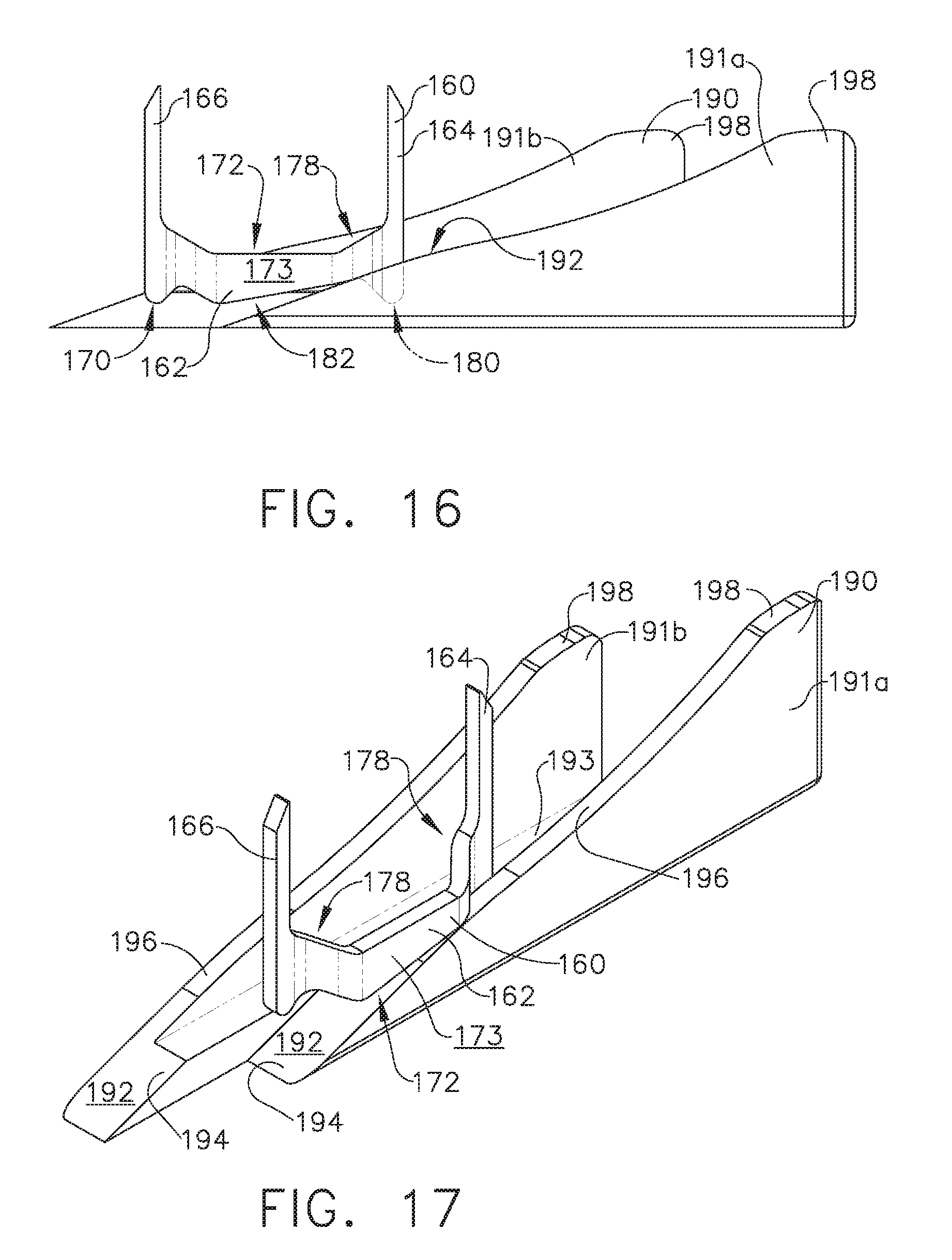
D00016

D00017

D00018

D00019

D00020
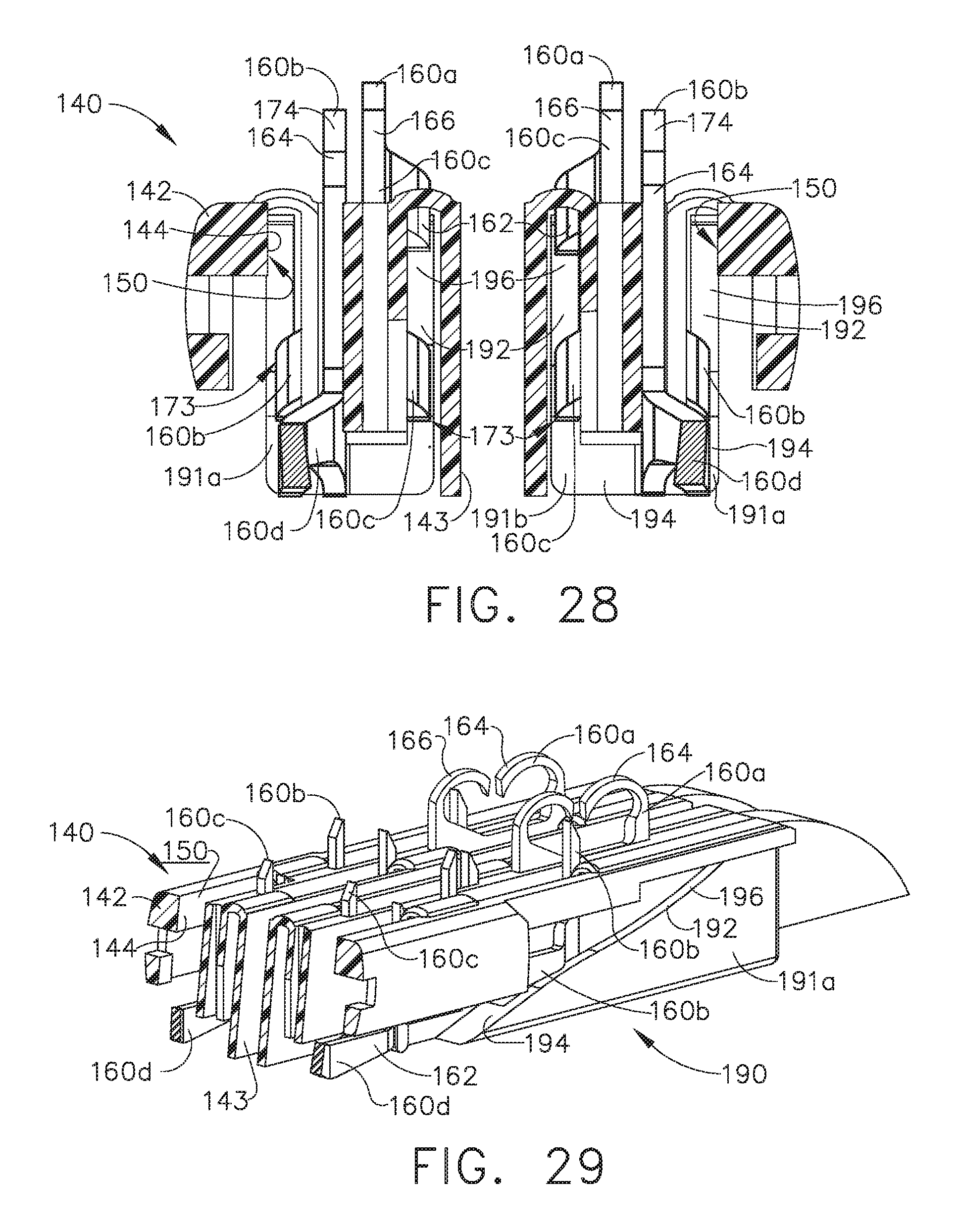
D00021

D00022

D00023

D00024

D00025

D00026

D00027

D00028

D00029
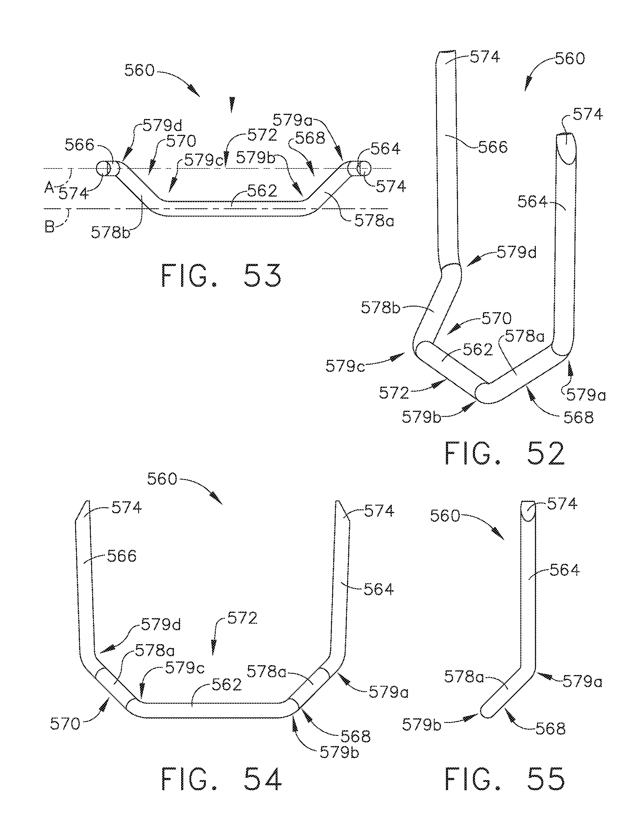
D00030

D00031

D00032

D00033

D00034

D00035
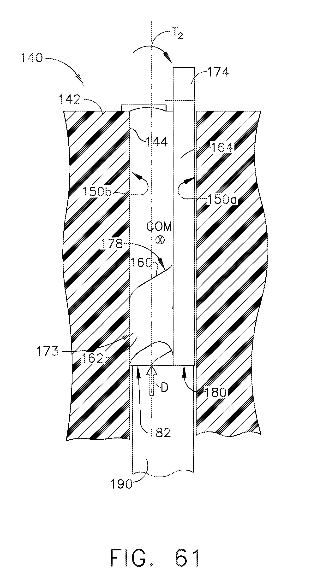
D00036
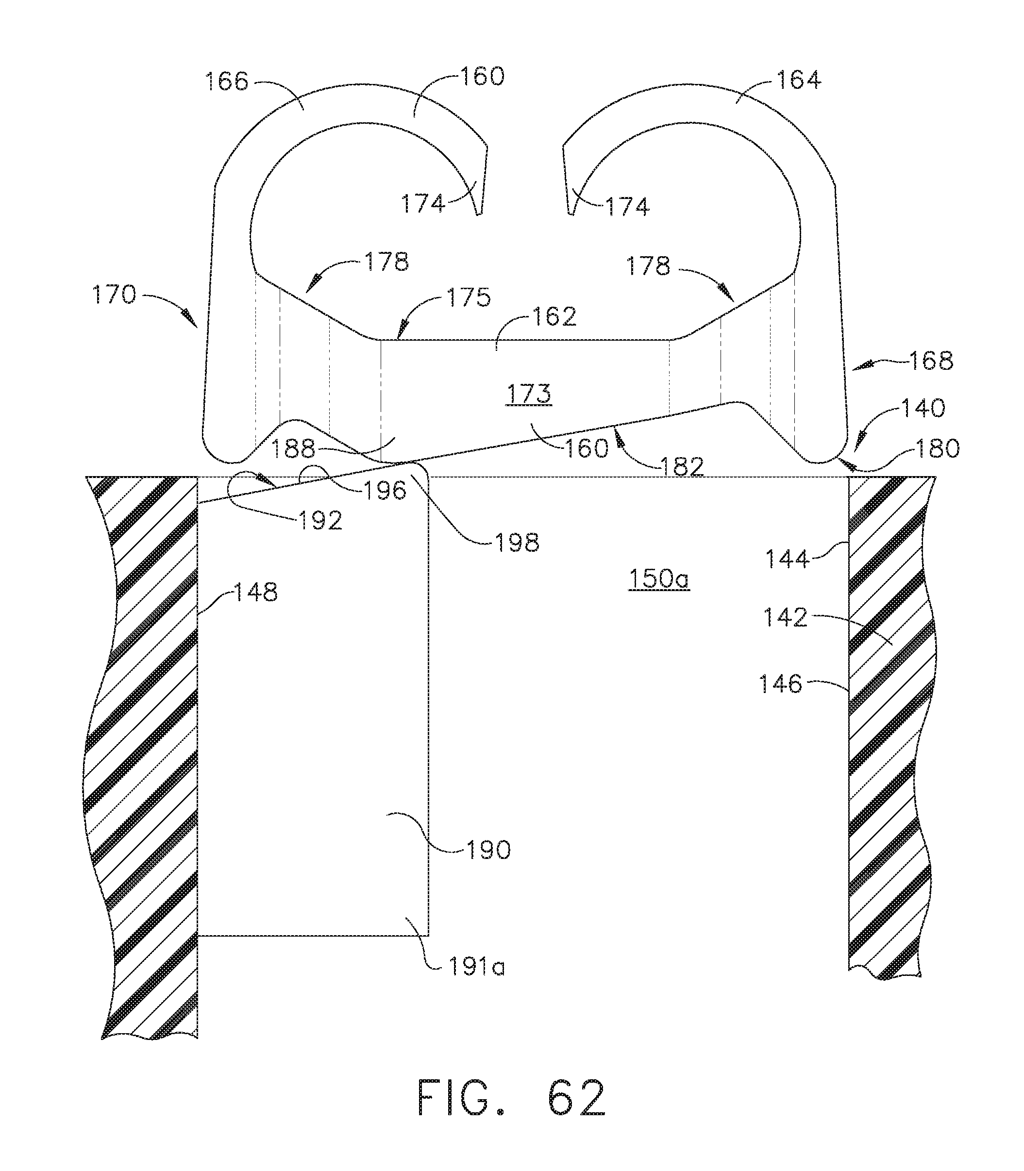
D00037

D00038
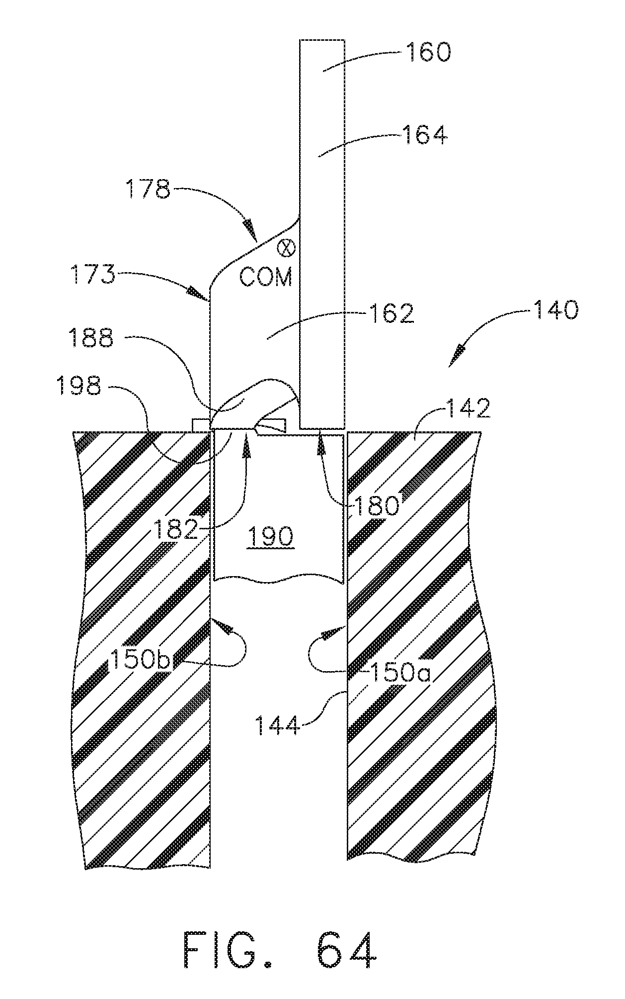
D00039

D00040

D00041

D00042

D00043
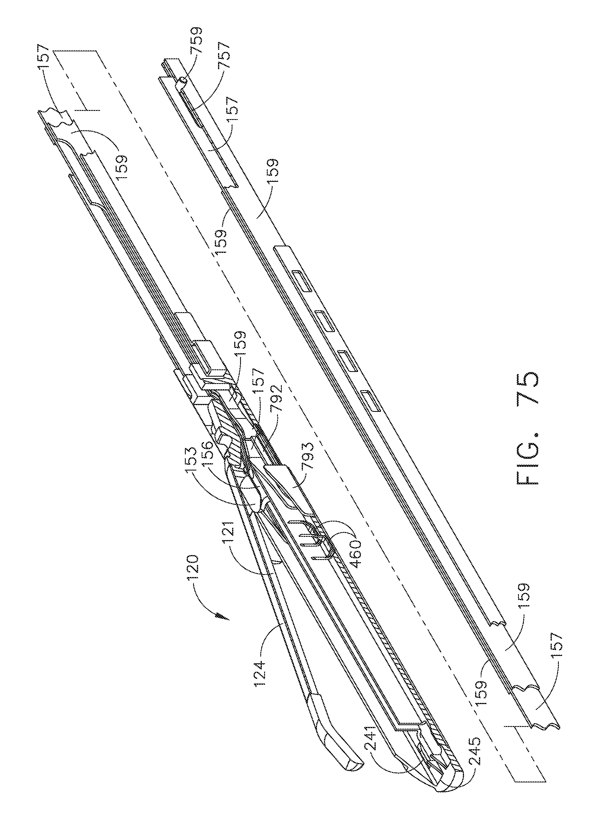
D00044

D00045

D00046

D00047

D00048

D00049

D00050

D00051

D00052

D00053

D00054
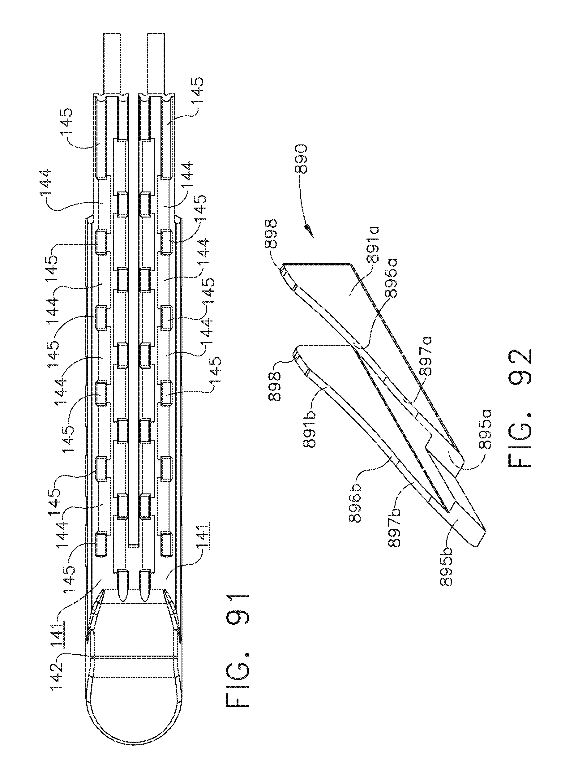
D00055

D00056
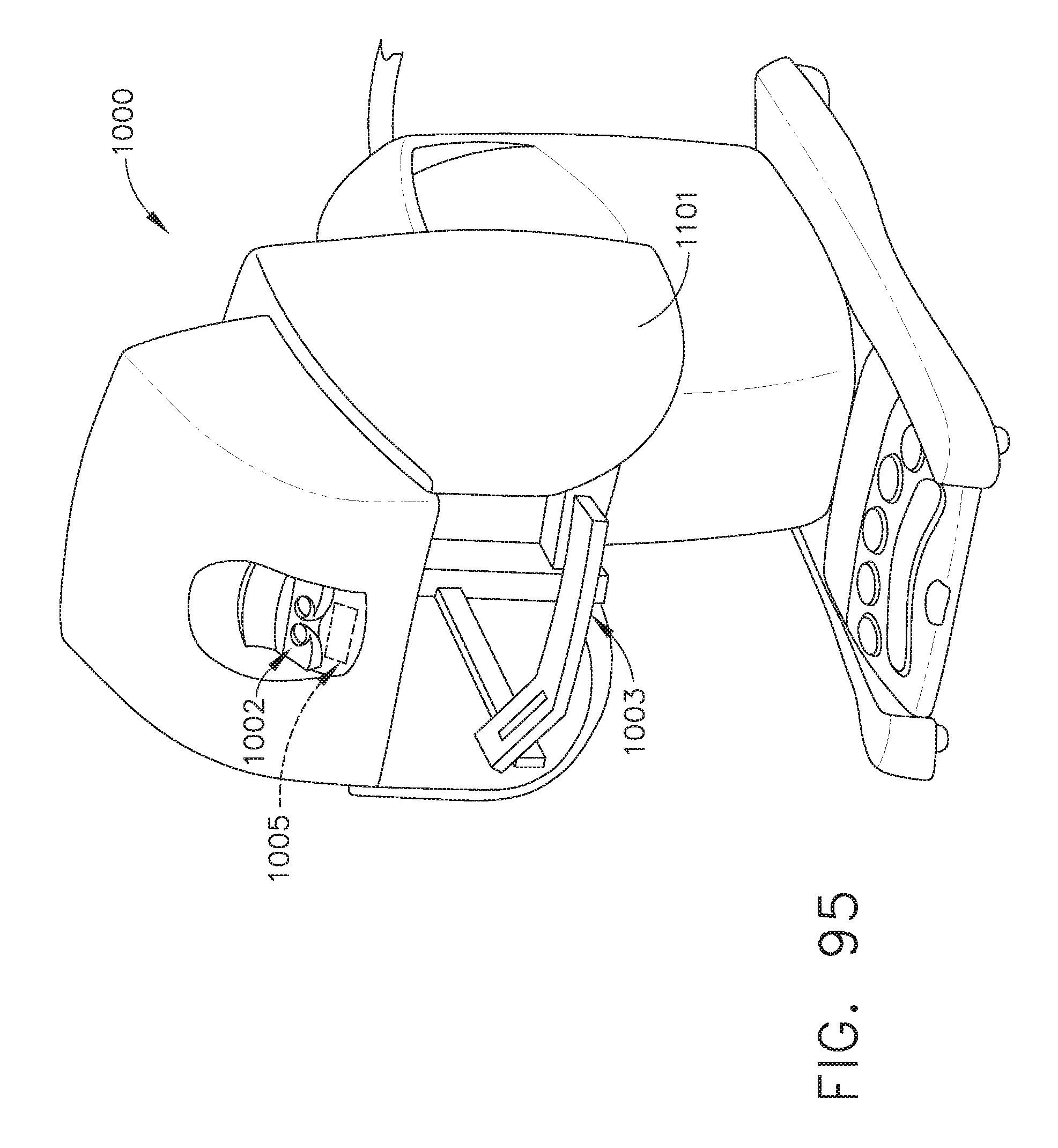
D00057

D00058

D00059

D00060
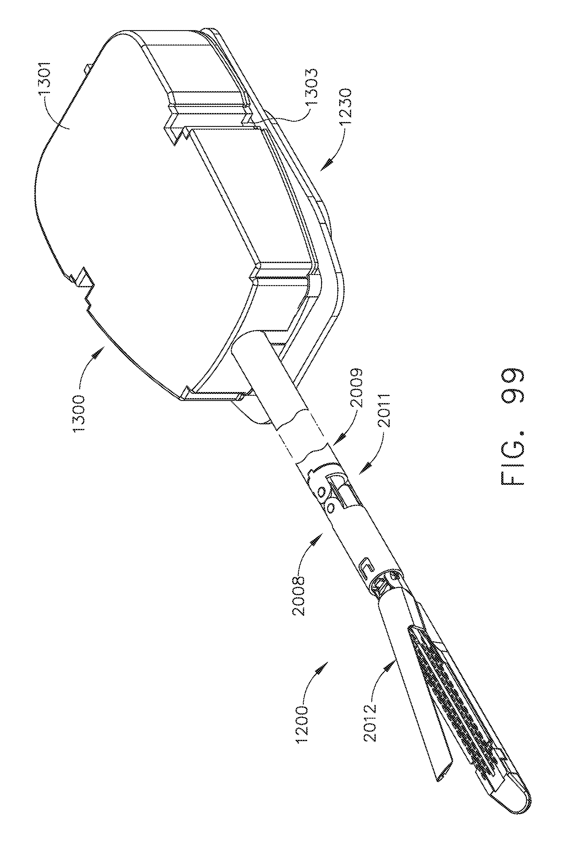
D00061

D00062

D00063
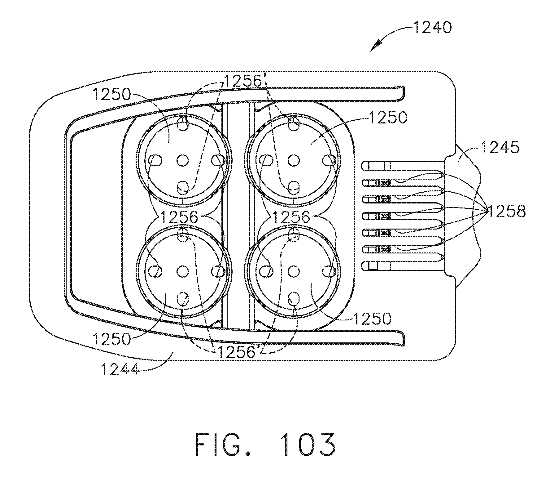
D00064

D00065
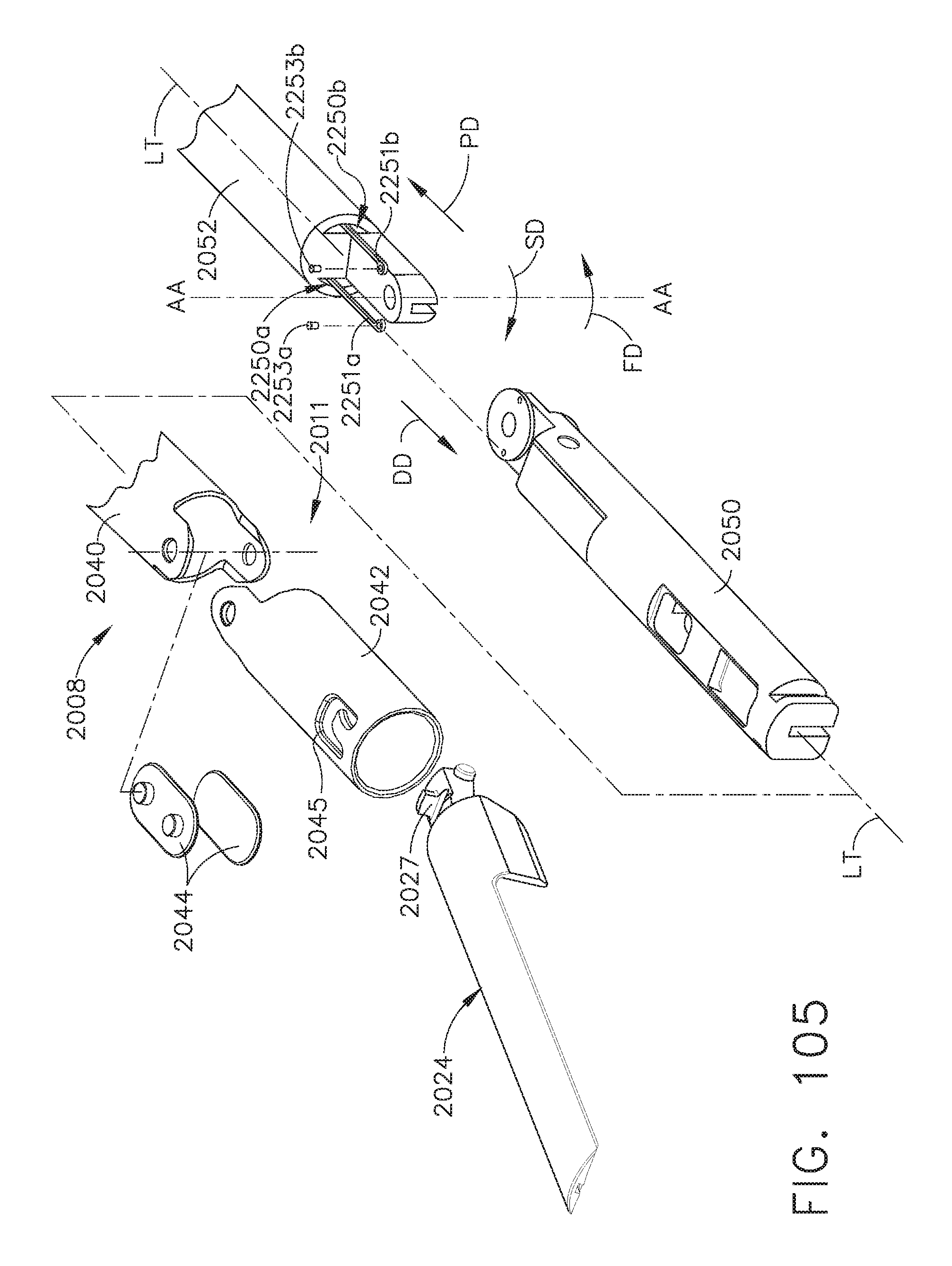
D00066

D00067

D00068
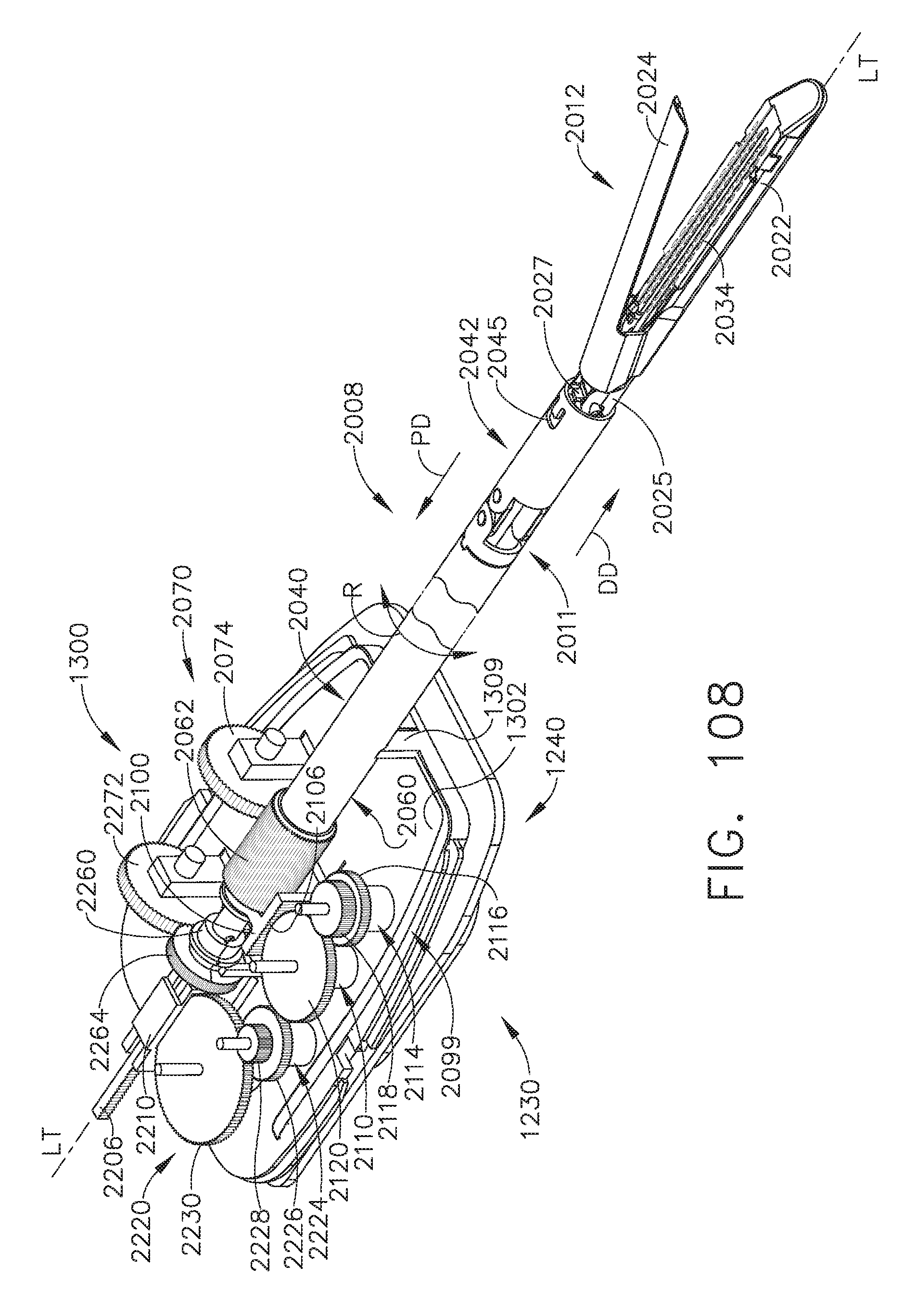
D00069

D00070

D00071

D00072

D00073
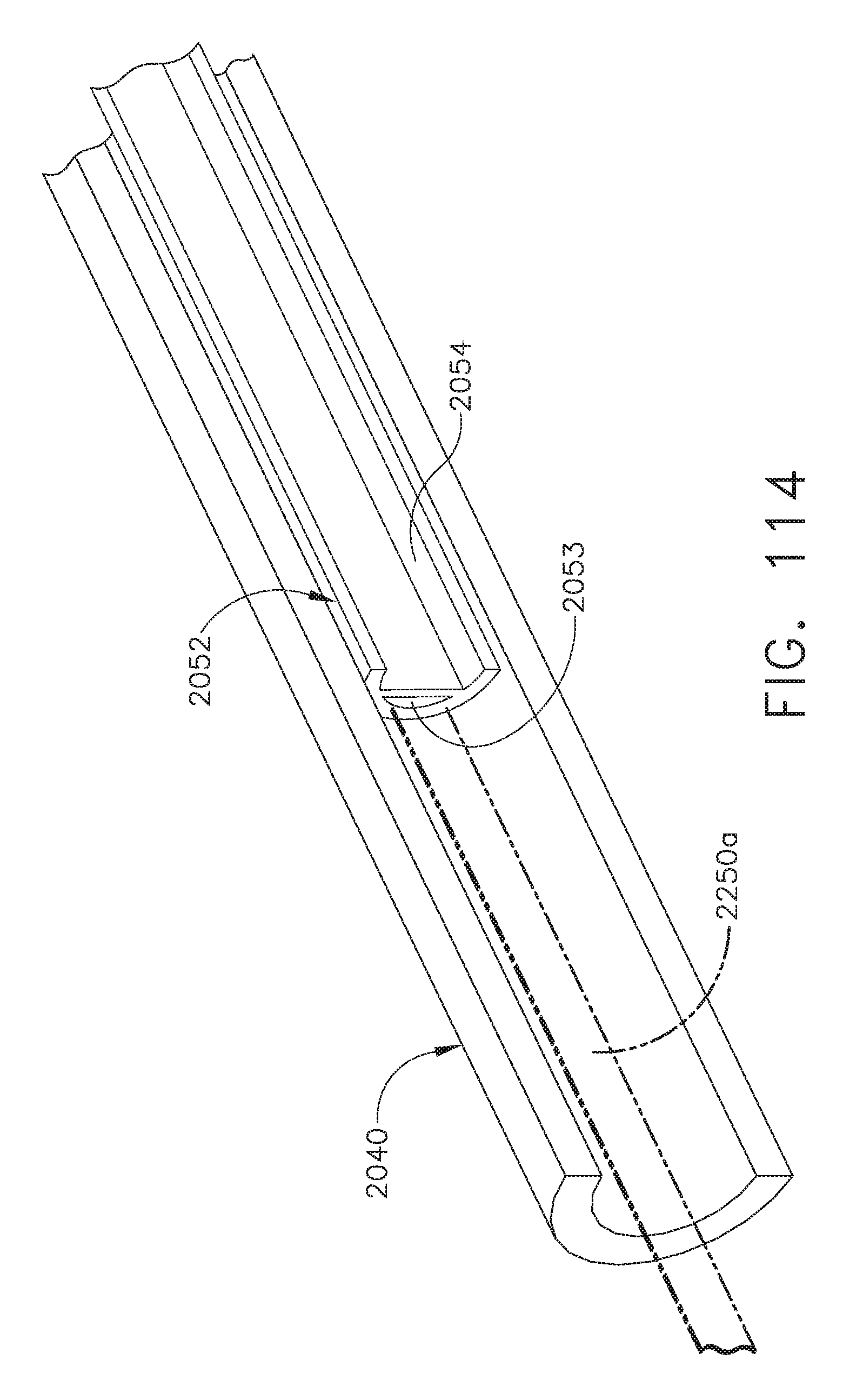
D00074

D00075
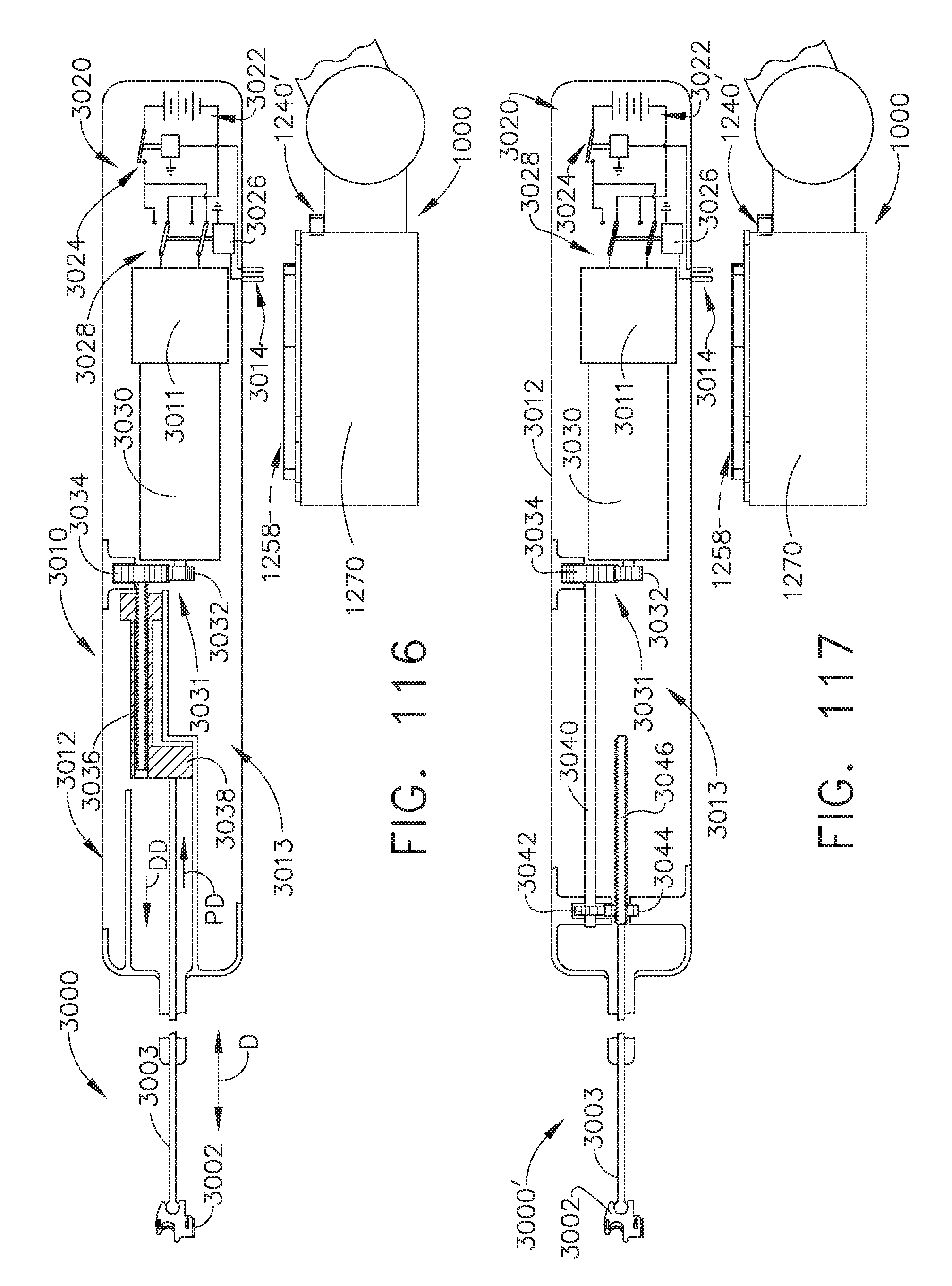
D00076

D00077

D00078

D00079
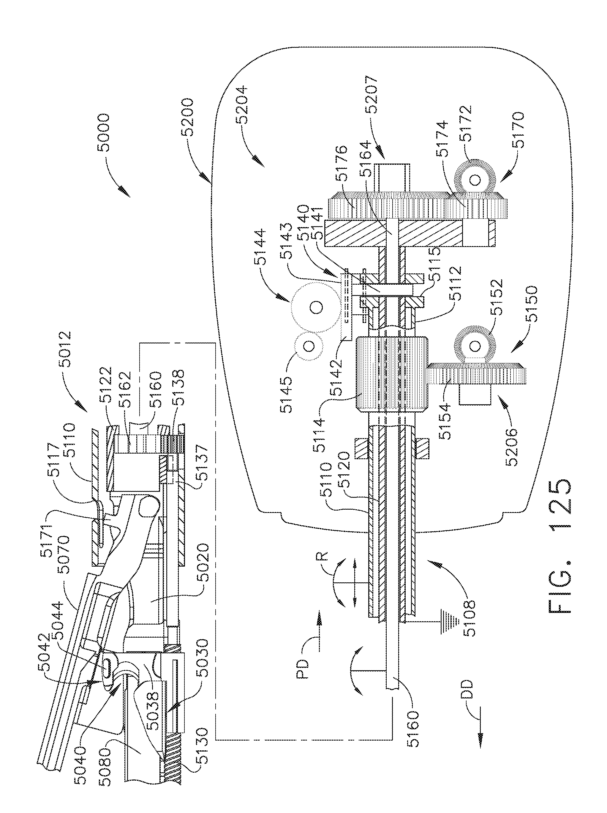
D00080

D00081
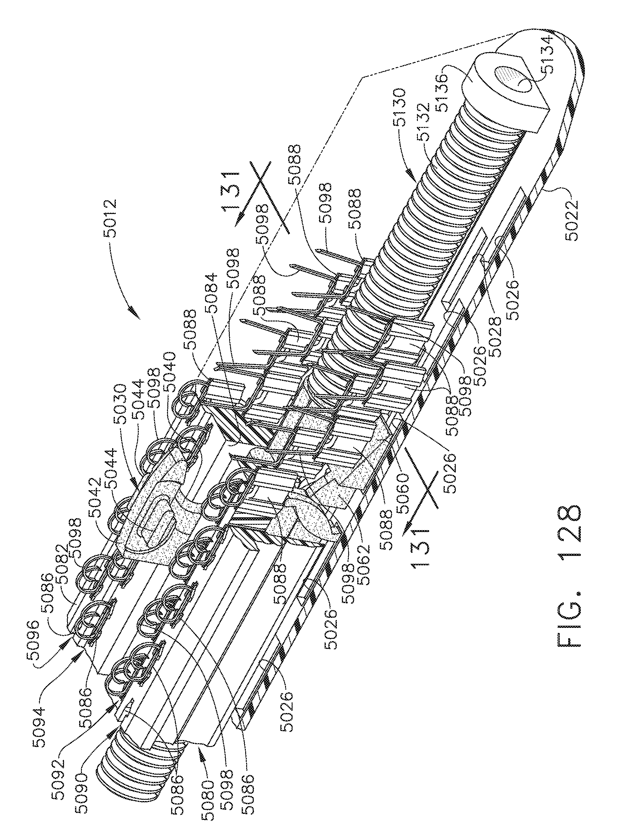
D00082

D00083

D00084

D00085

D00086

D00087

D00088

D00089

D00090

D00091

D00092

D00093

D00094
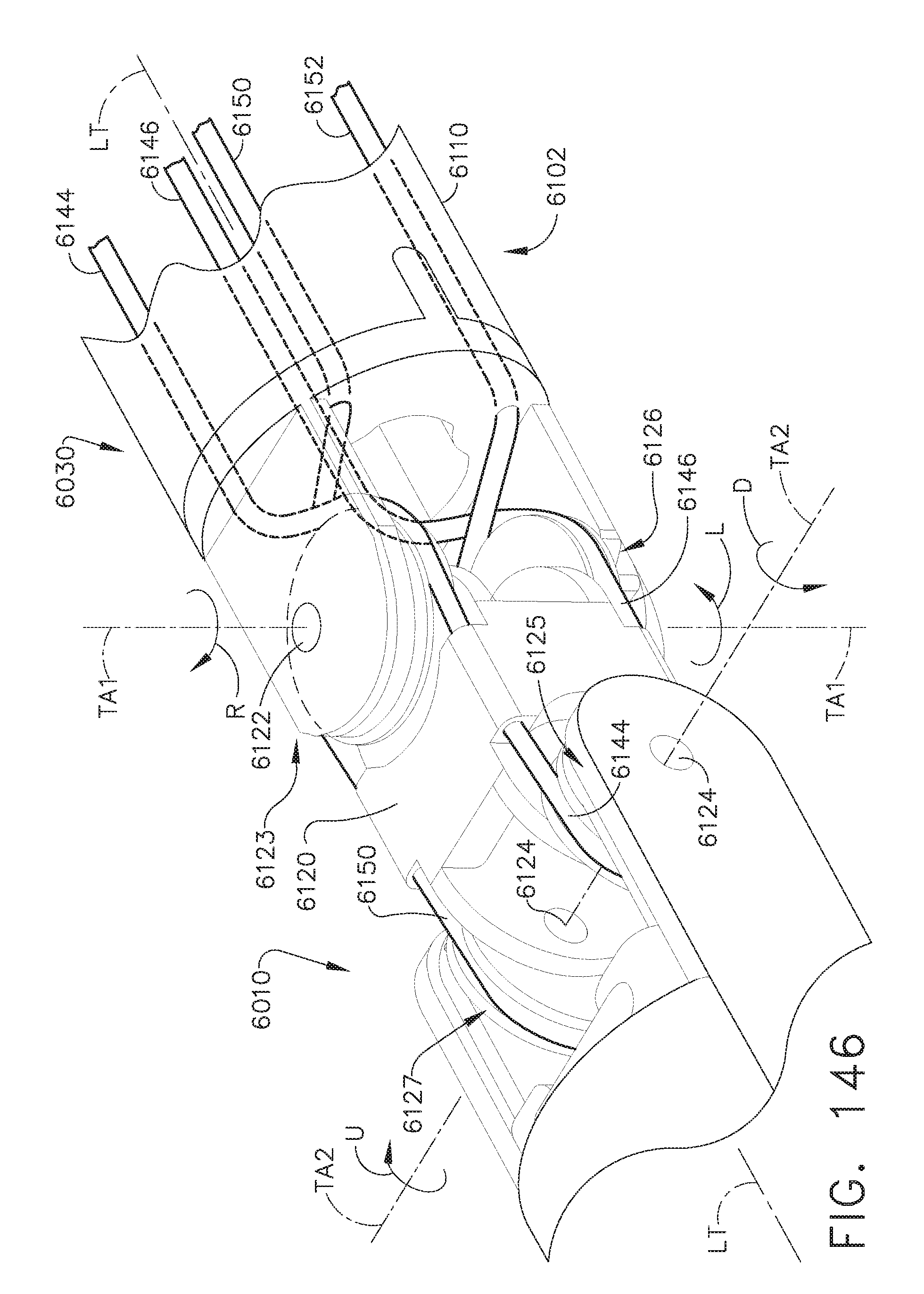
D00095

D00096

D00097

XML
uspto.report is an independent third-party trademark research tool that is not affiliated, endorsed, or sponsored by the United States Patent and Trademark Office (USPTO) or any other governmental organization. The information provided by uspto.report is based on publicly available data at the time of writing and is intended for informational purposes only.
While we strive to provide accurate and up-to-date information, we do not guarantee the accuracy, completeness, reliability, or suitability of the information displayed on this site. The use of this site is at your own risk. Any reliance you place on such information is therefore strictly at your own risk.
All official trademark data, including owner information, should be verified by visiting the official USPTO website at www.uspto.gov. This site is not intended to replace professional legal advice and should not be used as a substitute for consulting with a legal professional who is knowledgeable about trademark law.