Methods, devices and systems for receiving and decoding a signal in the presence of noise using slices and warping
Fleming , et al. De
U.S. patent number 10,498,572 [Application Number 16/121,736] was granted by the patent office on 2019-12-03 for methods, devices and systems for receiving and decoding a signal in the presence of noise using slices and warping. This patent grant is currently assigned to PROTEUS DIGITAL HEALTH, INC.. The grantee listed for this patent is Proteus Digital Health, Inc.. Invention is credited to Robert Fleming, Cherie Kushner, William H. McAllister, Mark Zdeblick.


View All Diagrams
| United States Patent | 10,498,572 |
| Fleming , et al. | December 3, 2019 |
Methods, devices and systems for receiving and decoding a signal in the presence of noise using slices and warping
Abstract
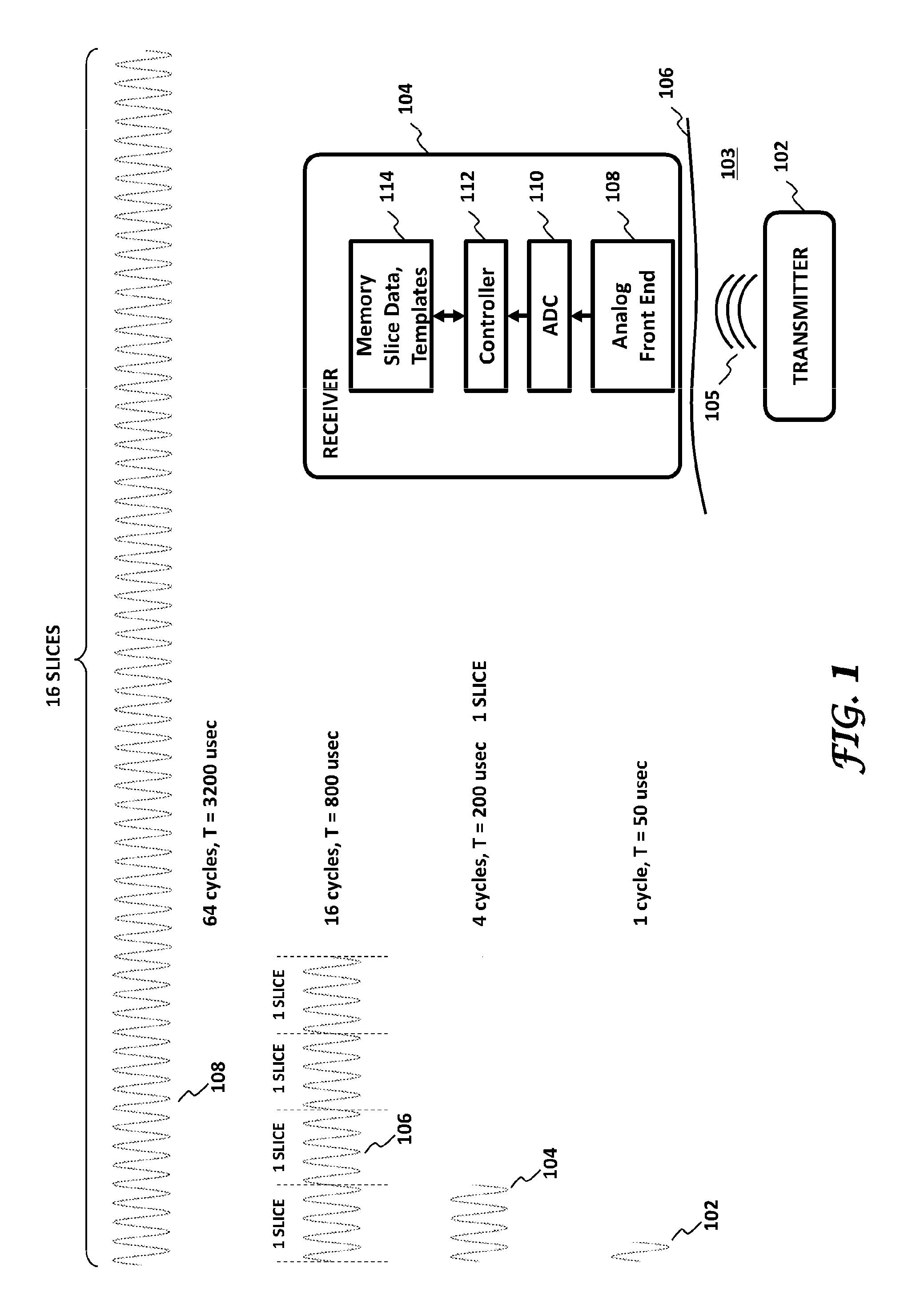
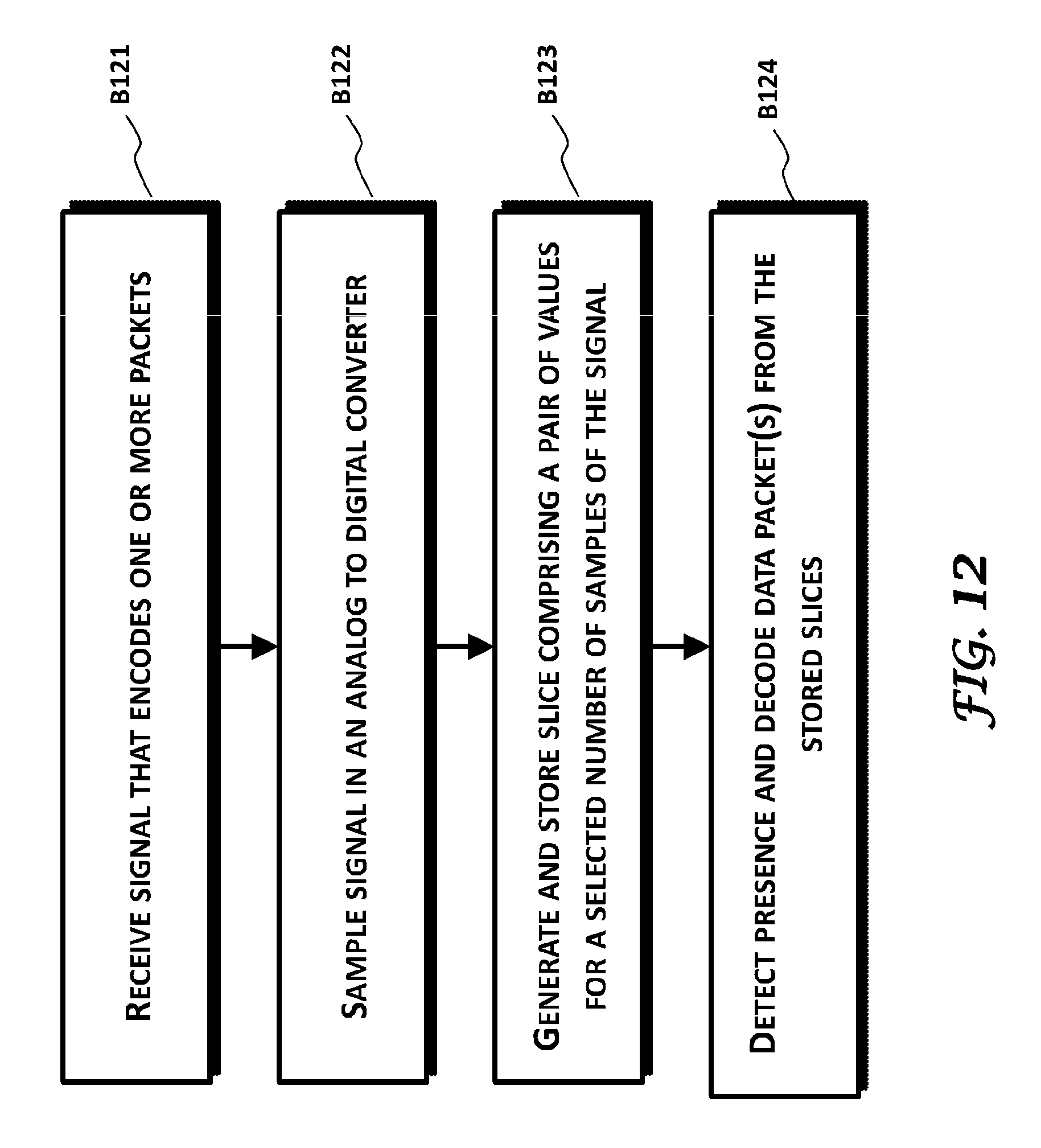
A method may comprise receiving and sampling a signal. The signal may encode a data packet. A slice may be generated and stored comprising a pair of values for each of a selected number of samples of the signal representing a correlation of the signal to reference functions in the receiver. The presence of the data packet may then be detected and the detected packet decoded from the stored slices. The generating and storing slices may be carried out as the received signal is sampled. The sampled values of the signal may be discarded as the slices are generated and stored. The slice representation of the signal can be manipulated to generate filters with flexible bandwidth and center frequency.
| Inventors: | Fleming; Robert (Nicasio, CA), Kushner; Cherie (Nicasio, CA), McAllister; William H. (Saratoga, CA), Zdeblick; Mark (Portola Valley, CA) | ||||||||||
|---|---|---|---|---|---|---|---|---|---|---|---|
| Applicant: |
|
||||||||||
| Assignee: | PROTEUS DIGITAL HEALTH, INC.
(Redwood City, CA) |
||||||||||
| Family ID: | 52689448 | ||||||||||
| Appl. No.: | 16/121,736 | ||||||||||
| Filed: | September 5, 2018 |
Prior Publication Data
| Document Identifier | Publication Date | |
|---|---|---|
| US 20190260618 A1 | Aug 22, 2019 | |
Related U.S. Patent Documents
| Application Number | Filing Date | Patent Number | Issue Date | ||
|---|---|---|---|---|---|
| 15678349 | Aug 16, 2017 | 10097388 | |||
| 14989409 | Oct 10, 2017 | 9787511 | |||
| 14491449 | Feb 23, 2016 | 9270503 | |||
| 61880786 | Sep 20, 2013 | ||||
| Current U.S. Class: | 1/1 |
| Current CPC Class: | H04B 1/001 (20130101); H04L 25/08 (20130101); H04L 69/22 (20130101); H04L 7/042 (20130101); H04L 27/148 (20130101); H04L 27/144 (20130101); H04L 27/0014 (20130101) |
| Current International Class: | H04L 27/14 (20060101); H04L 27/144 (20060101); H04L 7/04 (20060101); H04L 27/148 (20060101); H04B 1/00 (20060101); H04L 25/08 (20060101); H04L 29/06 (20060101); H04L 27/00 (20060101) |
References Cited [Referenced By]
U.S. Patent Documents
| 3340866 | September 1967 | Noller |
| 3607788 | September 1971 | Adolph |
| 3642008 | February 1972 | Bolduc |
| 3679480 | July 1972 | Brown et al. |
| 3682160 | August 1972 | Murata |
| 3719183 | March 1973 | Schwartz |
| 3828766 | August 1974 | Krasnow |
| 3837339 | September 1974 | Aisenberg et al. |
| 3989050 | November 1976 | Buchalter |
| 4067014 | January 1978 | Wheeler |
| 4077397 | March 1978 | Ellis |
| 4077398 | March 1978 | Ellis |
| 4082087 | April 1978 | Howson |
| 4090752 | May 1978 | Long |
| 4106348 | August 1978 | Auphan |
| 4121573 | October 1978 | Crovella et al. |
| 4129125 | December 1978 | Lester |
| 4149168 | April 1979 | Hose |
| 4166453 | September 1979 | McClelland |
| 4185172 | January 1980 | Melindo et al. |
| 4185175 | January 1980 | Kondo |
| 4239046 | December 1980 | Ong |
| 4269189 | May 1981 | Abraham |
| 4331654 | May 1982 | Morris |
| 4333150 | June 1982 | Matty |
| 4345588 | August 1982 | Widder et al. |
| 4418697 | December 1983 | Tama |
| 4425117 | January 1984 | Hugemann |
| 4494950 | January 1985 | Fischell |
| 4513385 | April 1985 | Muri |
| 4559950 | December 1985 | Vaughan |
| 4578061 | March 1986 | Lemelson |
| 4635641 | January 1987 | Hoffman |
| 4654165 | March 1987 | Eisenber |
| 4669479 | June 1987 | Dunseath |
| 4725997 | February 1988 | Urquhart et al. |
| 4749575 | June 1988 | Rotman et al. |
| 4763659 | August 1988 | Dunseath |
| 4784162 | November 1988 | Ricks |
| 4793825 | December 1988 | Benjamin et al. |
| 4809705 | March 1989 | Ascher |
| 4844076 | July 1989 | Lesho |
| 4858617 | August 1989 | Sanders |
| 4896261 | January 1990 | Nolan |
| 4975230 | December 1990 | Pinkhasov |
| 4987897 | January 1991 | Funke |
| 5016634 | May 1991 | Vock et al. |
| 5079006 | January 1992 | Urguhart |
| 5113859 | May 1992 | Funke |
| 5167626 | December 1992 | Casper |
| 5176626 | January 1993 | Soehendra |
| 5232383 | August 1993 | Barnick |
| 5245332 | September 1993 | Katzenstein et al. |
| 5261402 | November 1993 | DiSabito |
| 5263481 | November 1993 | Axelgaard et al. |
| 5281287 | January 1994 | Lloyd |
| 5283136 | February 1994 | Peled et al. |
| 5288564 | February 1994 | Klein |
| 5318557 | June 1994 | Gross |
| 5394882 | March 1995 | Mawhinney |
| 5458141 | October 1995 | Neil et al. |
| 5473612 | December 1995 | Dehner, Jr. |
| 5485841 | January 1996 | Watkin et al. |
| 5511548 | April 1996 | Riazzi et al. |
| 5551020 | August 1996 | Flax et al. |
| 5596302 | January 1997 | Mastrocola et al. |
| D377983 | February 1997 | Sabri et al. |
| 5623520 | April 1997 | Kaiser |
| 5634466 | June 1997 | Gruner |
| 5634468 | June 1997 | Platt |
| 5645063 | July 1997 | Straka et al. |
| 5720771 | February 1998 | Snell |
| 5724432 | March 1998 | Bouvet et al. |
| 5740811 | April 1998 | Hedberg |
| 5792048 | August 1998 | Schaefer |
| 5802467 | September 1998 | Salazar |
| 5833716 | November 1998 | Bar-Or |
| 5845265 | December 1998 | Woolston |
| 5862803 | January 1999 | Besson |
| 5862808 | January 1999 | Albarello |
| 5868136 | February 1999 | Fox |
| 5921925 | July 1999 | Cartmell et al. |
| 5925030 | July 1999 | Gross et al. |
| 5925066 | July 1999 | Kroll et al. |
| 5957854 | September 1999 | Besson et al. |
| 5974124 | October 1999 | Schlueter, Jr. et al. |
| 5981166 | November 1999 | Mandecki |
| 5999846 | December 1999 | Pardey et al. |
| 6023631 | February 2000 | Cartmell et al. |
| 6038464 | March 2000 | Axelgaard et al. |
| 6042710 | March 2000 | Dubrow |
| 6047203 | April 2000 | Sackner |
| 6076016 | June 2000 | Feierbach |
| 6081734 | June 2000 | Batz |
| 6095985 | August 2000 | Raymond et al. |
| 6115636 | September 2000 | Ryan |
| 6117077 | September 2000 | Del Mar et al. |
| 6122351 | September 2000 | Schlueter, Jr. et al. |
| 6141592 | October 2000 | Pauly |
| 6151353 | November 2000 | Harrison et al. |
| 6200265 | March 2001 | Walsh et al. |
| 6200625 | March 2001 | Beckett |
| 6204764 | March 2001 | Maloney |
| 6206702 | March 2001 | Hayden et al. |
| 6217744 | April 2001 | Crosby |
| 6231593 | May 2001 | Meserol |
| 6238338 | May 2001 | DeLuca et al. |
| 6245057 | June 2001 | Sieben et al. |
| 6275476 | August 2001 | Wood |
| 6285897 | September 2001 | Kilcoyne et al. |
| 6287252 | September 2001 | Lugo |
| 6289238 | September 2001 | Besson et al. |
| 6301298 | October 2001 | Kuntz et al. |
| 6315719 | November 2001 | Rode et al. |
| 6317714 | November 2001 | Del Castillo |
| 6358202 | March 2002 | Arent |
| 6364834 | April 2002 | Reuss |
| 6366206 | April 2002 | Ishikawa et al. |
| 6371927 | April 2002 | Brune |
| 6374670 | April 2002 | Spelman |
| 6380858 | April 2002 | Yarin et al. |
| 6394953 | May 2002 | Devlin et al. |
| 6394997 | May 2002 | Lemelson |
| 6409674 | June 2002 | Brockway et al. |
| 6426863 | July 2002 | Munshi |
| 6432292 | August 2002 | Pinto et al. |
| 6440069 | August 2002 | Raymond et al. |
| 6441747 | August 2002 | Khair |
| 6477424 | November 2002 | Thompson et al. |
| 6482156 | November 2002 | Lliff |
| 6494829 | December 2002 | New et al. |
| 6496705 | December 2002 | Ng et al. |
| 6526315 | February 2003 | Inagawa |
| 6544174 | April 2003 | West |
| 6564079 | May 2003 | Cory |
| 6577893 | June 2003 | Besson et al. |
| 6579231 | June 2003 | Phipps |
| 6605038 | August 2003 | Teller et al. |
| 6605046 | August 2003 | Del Mar |
| 6609018 | August 2003 | Cory |
| 6612984 | September 2003 | Kerr |
| 6632175 | October 2003 | Marshall |
| 6632216 | October 2003 | Houzego et al. |
| 6643541 | November 2003 | Mok et al. |
| 6654638 | November 2003 | Sweeney |
| 6663846 | December 2003 | McCombs |
| 6673474 | January 2004 | Yamamoto |
| 6680923 | January 2004 | Leon |
| 6689117 | February 2004 | Sweeney et al. |
| 6694161 | February 2004 | Mehrotra |
| 6704602 | March 2004 | Berg et al. |
| 6720923 | April 2004 | Hayward et al. |
| 6738671 | May 2004 | Christophersom et al. |
| 6740033 | May 2004 | Olejniczak et al. |
| 6745082 | June 2004 | Axelgaard et al. |
| 6755783 | June 2004 | Cosentino |
| 6757523 | June 2004 | Fry |
| 6800060 | October 2004 | Marshall |
| 6801137 | October 2004 | Eggers et al. |
| 6807438 | October 2004 | Brun Del Re et al. |
| 6814706 | November 2004 | Barton et al. |
| 6822554 | November 2004 | Vrijens et al. |
| 6836862 | December 2004 | Erekson et al. |
| 6839659 | January 2005 | Tarassenko et al. |
| 6840904 | January 2005 | Goldberg |
| 6842636 | January 2005 | Perrault |
| 6845272 | January 2005 | Thomsen |
| 6856832 | February 2005 | Matsumura et al. |
| 6864780 | March 2005 | Doi |
| 6879810 | April 2005 | Bouet |
| 6882881 | April 2005 | Lesser et al. |
| 6889165 | May 2005 | Lind et al. |
| 6897788 | May 2005 | Khair et al. |
| 6909878 | June 2005 | Haller |
| 6922592 | July 2005 | Thompson et al. |
| 6928370 | August 2005 | Anuzis et al. |
| 6929636 | August 2005 | Von Alten |
| 6937150 | August 2005 | Medema |
| 6942616 | September 2005 | Kerr |
| 6951536 | October 2005 | Yokoi |
| 6956917 | October 2005 | Lenosky |
| 6957107 | October 2005 | Rogers et al. |
| 6959929 | November 2005 | Pugnet et al. |
| 6961601 | November 2005 | Mathews et al. |
| 6968153 | November 2005 | Heinonen |
| 6987965 | January 2006 | Ng et al. |
| 6990082 | January 2006 | Zehavi et al. |
| 7002476 | February 2006 | Rapchak |
| 7004395 | February 2006 | Koenck |
| 7009634 | March 2006 | Iddan et al. |
| 7009946 | March 2006 | Kardach |
| 7013162 | March 2006 | Gorsuch |
| 7016648 | March 2006 | Haller |
| 7020508 | March 2006 | Stivoric |
| 7024248 | April 2006 | Penner et al. |
| 7031745 | April 2006 | Shen |
| 7031857 | April 2006 | Tarassenko et al. |
| 7039453 | May 2006 | Mullick |
| 7046649 | May 2006 | Awater et al. |
| 7076437 | July 2006 | Levy |
| 7116252 | October 2006 | Teraguchi |
| 7118531 | October 2006 | Krill |
| 7127300 | October 2006 | Mazar et al. |
| 7139332 | November 2006 | Yu et al. |
| 7146228 | December 2006 | Nielsen |
| 7146449 | December 2006 | Do et al. |
| 7149581 | December 2006 | Goedeke et al. |
| 7154071 | December 2006 | Sattler et al. |
| 7154916 | December 2006 | Soloff |
| 7155232 | December 2006 | Godfrey et al. |
| 7160258 | January 2007 | Imran |
| 7161484 | January 2007 | Tsoukalis |
| 7164942 | January 2007 | Avrahami |
| 7171166 | January 2007 | Ng et al. |
| 7171177 | January 2007 | Park et al. |
| 7171259 | January 2007 | Rytky |
| 7187960 | March 2007 | Abreu |
| 7188199 | March 2007 | Leung et al. |
| 7188767 | March 2007 | Penuela |
| 7194038 | March 2007 | Inkinen |
| 7206630 | April 2007 | Tarler |
| 7209790 | April 2007 | Thompson et al. |
| 7215660 | May 2007 | Perlman |
| 7215991 | May 2007 | Besson |
| 7218967 | May 2007 | Bergelson |
| 7231451 | June 2007 | Law |
| 7243118 | July 2007 | Lou |
| 7246521 | July 2007 | Kim |
| 7249212 | July 2007 | Do |
| 7252792 | August 2007 | Perrault |
| 7253716 | August 2007 | Lovoi et al. |
| 7261690 | August 2007 | Teller |
| 7270633 | September 2007 | Goscha |
| 7273454 | September 2007 | Raymond et al. |
| 7283867 | October 2007 | Strother et al. |
| 7285090 | October 2007 | Stivoric et al. |
| 7289855 | October 2007 | Nghiem |
| 7291497 | November 2007 | Holmes |
| 7292139 | November 2007 | Mazar et al. |
| 7294105 | November 2007 | Islam |
| 7311665 | December 2007 | Hawthorne |
| 7313163 | December 2007 | Liu |
| 7317378 | January 2008 | Jarvis et al. |
| 7318808 | January 2008 | Tarassenko et al. |
| 7336929 | February 2008 | Yasuda |
| 7342895 | March 2008 | Serpa |
| 7346380 | March 2008 | Axelgaard et al. |
| 7349722 | March 2008 | Witkowski et al. |
| 7352998 | April 2008 | Palin |
| 7353258 | April 2008 | Washburn |
| 7357891 | April 2008 | Yang et al. |
| 7359674 | April 2008 | Markki |
| 7366558 | April 2008 | Virtanen et al. |
| 7373196 | May 2008 | Ryu et al. |
| 7375739 | May 2008 | Robbins |
| 7376435 | May 2008 | McGowan |
| 7382247 | June 2008 | Welch et al. |
| 7382263 | June 2008 | Danowski et al. |
| 7387607 | June 2008 | Holt |
| 7388903 | June 2008 | Godfrey et al. |
| 7389088 | June 2008 | Kim |
| 7392015 | June 2008 | Farlow |
| 7395105 | July 2008 | Schmidt et al. |
| 7395106 | July 2008 | Ryu et al. |
| 7396330 | July 2008 | Banet |
| 7404968 | July 2008 | Abrams et al. |
| 7413544 | August 2008 | Kerr |
| 7414534 | August 2008 | Kroll et al. |
| 7415242 | August 2008 | Ngan |
| 7424268 | September 2008 | Diener |
| 7424319 | September 2008 | Muehlsteff |
| 7427266 | September 2008 | Ayer et al. |
| 7471665 | December 2008 | Perlman |
| 7476104 | January 2009 | Marmaropoulos et al. |
| 7499674 | March 2009 | Salokannel |
| 7502643 | March 2009 | Farringdon et al. |
| 7505795 | March 2009 | Lim et al. |
| 7510121 | March 2009 | Koenck |
| 7512448 | March 2009 | Malick |
| 7515043 | April 2009 | Welch |
| 7523756 | April 2009 | Minai |
| 7525426 | April 2009 | Edelstein |
| 7539533 | May 2009 | Tran |
| 7542878 | June 2009 | Nanikashvili |
| 7547278 | June 2009 | Miyazaki et al. |
| 7551590 | June 2009 | Haller |
| 7554452 | June 2009 | Cole |
| 7575005 | August 2009 | Mumford |
| 7599003 | October 2009 | Suzuki et al. |
| 7616111 | November 2009 | Covannon |
| 7616710 | November 2009 | Kim et al. |
| 7617001 | November 2009 | Penner et al. |
| 7626387 | December 2009 | Adachi |
| 7640802 | January 2010 | King et al. |
| 7647112 | January 2010 | Tracey |
| 7647185 | January 2010 | Tarassenko et al. |
| 7653031 | January 2010 | Godfrey et al. |
| 7668437 | February 2010 | Yamada et al. |
| 7672703 | March 2010 | Yeo et al. |
| 7672714 | March 2010 | Kuo |
| 7673679 | March 2010 | Harrison et al. |
| 7678043 | March 2010 | Gilad |
| 7688204 | March 2010 | Yamanaka et al. |
| 7689437 | March 2010 | Teller et al. |
| 7697994 | April 2010 | VanDanacker et al. |
| 7720036 | May 2010 | Sadri |
| 7729776 | June 2010 | Von Arx et al. |
| 7733224 | June 2010 | Tran |
| 7736318 | June 2010 | Costentino |
| 7750790 | July 2010 | Yang et al. |
| 7756587 | July 2010 | Penner et al. |
| 7782991 | August 2010 | Sobchak et al. |
| 7797033 | September 2010 | D'Andrea et al. |
| 7809399 | October 2010 | Lu |
| 7844341 | November 2010 | Von Arx et al. |
| 7874993 | January 2011 | Bardy |
| 7885700 | February 2011 | Clark et al. |
| 7904133 | March 2011 | Gehman et al. |
| 7940933 | May 2011 | Corndorf |
| D639437 | June 2011 | Bishay et al. |
| 7978064 | July 2011 | Zdeblick et al. |
| 7983189 | July 2011 | Bugenhagen |
| 8036748 | October 2011 | Zdeblick et al. |
| 8055334 | November 2011 | Savage et al. |
| 8073707 | December 2011 | Teller et al. |
| 8083128 | December 2011 | Dembo et al. |
| 8094807 | January 2012 | Ishibashi et al. |
| 8114021 | February 2012 | Robertson et al. |
| 8123576 | February 2012 | Kim |
| 8140143 | March 2012 | Picard et al. |
| 8160672 | April 2012 | Kim et al. |
| 8170515 | May 2012 | Le Reverend et al. |
| 8177611 | May 2012 | Kang |
| 8180425 | May 2012 | Selvitelli et al. |
| 8184854 | May 2012 | Bartsch |
| 8185191 | May 2012 | Shapiro et al. |
| 8185646 | May 2012 | Headley |
| 8190230 | May 2012 | Rytky |
| 8193821 | June 2012 | Mueller |
| 8200320 | June 2012 | Kovacs |
| 8214007 | July 2012 | Baker et al. |
| 8238998 | August 2012 | Park |
| 8249686 | August 2012 | Libbus et al. |
| 8253586 | August 2012 | Matak |
| 8254853 | August 2012 | Rofougaran |
| 8285356 | October 2012 | Bly et al. |
| 8290574 | October 2012 | Felid et al. |
| 8301232 | October 2012 | Albert et al. |
| 8308640 | November 2012 | Baldus et al. |
| 8315687 | November 2012 | Cross et al. |
| 8321672 | November 2012 | Asano |
| 8332009 | December 2012 | McLaughlin et al. |
| 8360976 | January 2013 | Imran |
| 8369936 | February 2013 | Farringdon et al. |
| 8386009 | February 2013 | Lindberg et al. |
| 8404275 | March 2013 | Habboushe |
| 8440274 | May 2013 | Wang |
| 8454528 | June 2013 | Yuen et al. |
| 8471960 | June 2013 | Lin et al. |
| 8514979 | August 2013 | Laporte |
| 8515559 | August 2013 | Roberts et al. |
| 8538544 | September 2013 | Sivard |
| 8545436 | October 2013 | Robertson et al. |
| 8548033 | October 2013 | Nemeth et al. |
| 8604974 | December 2013 | Ganeshan |
| 8615290 | December 2013 | Lin et al. |
| 8620402 | December 2013 | Parker, III et al. |
| 8634838 | January 2014 | Hellwig et al. |
| 8660645 | February 2014 | Stevenson et al. |
| 8668643 | March 2014 | Kinast |
| 8725243 | May 2014 | Dilorenzo et al. |
| 8730031 | May 2014 | Thompson et al. |
| 8754799 | June 2014 | Coln et al. |
| 8773258 | July 2014 | Vosch et al. |
| 8776198 | July 2014 | Tsitkova et al. |
| 8836513 | September 2014 | Hafezi et al. |
| 8838217 | September 2014 | Myr |
| 8858432 | October 2014 | Robertson |
| 8886281 | November 2014 | Pernu et al. |
| 8892194 | November 2014 | Balji et al. |
| 8908943 | December 2014 | Berry et al. |
| 8920345 | December 2014 | Greenberg |
| 8923956 | December 2014 | Clark et al. |
| 8926509 | January 2015 | Magar et al. |
| 8932221 | January 2015 | Colliou et al. |
| 8945005 | February 2015 | Hafezi et al. |
| 8945328 | February 2015 | Longinotti et al. |
| 8989837 | March 2015 | Weinstein et al. |
| 9014779 | April 2015 | Zdeblick et al. |
| 9031658 | May 2015 | Chiao et al. |
| 9149577 | October 2015 | Robertson et al. |
| 9158890 | October 2015 | Meredith et al. |
| 9189941 | November 2015 | Eschelman et al. |
| 9211069 | December 2015 | Larson et al. |
| 9226663 | January 2016 | Fei |
| 9226679 | January 2016 | Balda |
| 9270025 | February 2016 | Robertson et al. |
| 9270503 | February 2016 | Kushner et al. |
| 9277864 | March 2016 | Yang et al. |
| 9439566 | September 2016 | Arne et al. |
| 9439582 | September 2016 | Berkman et al. |
| 9439599 | September 2016 | Thompson et al. |
| 9517012 | December 2016 | Lane et al. |
| 9577864 | February 2017 | Kushner et al. |
| 9597010 | March 2017 | Thompson et al. |
| 9659423 | May 2017 | Robertson et al. |
| 9756874 | September 2017 | Arne et al. |
| 9787511 | October 2017 | Fleming et al. |
| 9820658 | November 2017 | Tran |
| 9946297 | April 2018 | Nazzaro et al. |
| 1009738 | October 2018 | Fleming et al. |
| 2001/0027331 | October 2001 | Thompson |
| 2001/0031071 | October 2001 | Nichols et al. |
| 2001/0044588 | November 2001 | Mault |
| 2001/0051766 | December 2001 | Gazdinski |
| 2001/0056262 | December 2001 | Cabiri et al. |
| 2002/0002326 | January 2002 | Causey et al. |
| 2002/0026111 | February 2002 | Ackerman |
| 2002/0040278 | April 2002 | Anuzis et al. |
| 2002/0077620 | June 2002 | Sweeney et al. |
| 2002/0128934 | September 2002 | Shaer |
| 2002/0132226 | September 2002 | Nair |
| 2002/0169696 | November 2002 | Zara |
| 2002/0192159 | December 2002 | Reitberg |
| 2002/0193669 | December 2002 | Glukhovsky |
| 2002/0198470 | December 2002 | Imran et al. |
| 2003/0017826 | January 2003 | Fishman |
| 2003/0023150 | January 2003 | Yokoi et al. |
| 2003/0028226 | February 2003 | Thompson |
| 2003/0065536 | April 2003 | Hansen |
| 2003/0076179 | April 2003 | Branch et al. |
| 2003/0083559 | May 2003 | Thompson |
| 2003/0091121 | May 2003 | Kenmochi |
| 2003/0126593 | July 2003 | Mault |
| 2003/0130714 | July 2003 | Nielsen et al. |
| 2003/0135128 | July 2003 | Suffin et al. |
| 2003/0135392 | July 2003 | Vrijens et al. |
| 2003/0152622 | August 2003 | Louie-Helm et al. |
| 2003/0158466 | August 2003 | Lynn et al. |
| 2003/0158756 | August 2003 | Abramson |
| 2003/0162556 | August 2003 | Libes |
| 2003/0164401 | September 2003 | Andreasson et al. |
| 2003/0167000 | September 2003 | Mullick et al. |
| 2003/0171791 | September 2003 | KenKnight |
| 2003/0171898 | September 2003 | Tarassenko et al. |
| 2003/0181788 | September 2003 | Yokoi et al. |
| 2003/0181815 | September 2003 | Ebner et al. |
| 2003/0185286 | October 2003 | Yuen |
| 2003/0187337 | October 2003 | Tarassenko et al. |
| 2003/0187338 | October 2003 | Say et al. |
| 2003/0195403 | October 2003 | Berner et al. |
| 2003/0208113 | November 2003 | Mault et al. |
| 2003/0213495 | November 2003 | Fujita et al. |
| 2003/0214579 | November 2003 | Iddan |
| 2003/0216622 | November 2003 | Meron et al. |
| 2003/0216625 | November 2003 | Phipps |
| 2003/0216666 | November 2003 | Ericson et al. |
| 2003/0216729 | November 2003 | Marchitto |
| 2003/0229382 | December 2003 | Sun et al. |
| 2004/0008123 | January 2004 | Carrender et al. |
| 2004/0018476 | January 2004 | LaDue |
| 2004/0019172 | January 2004 | Yang et al. |
| 2004/0034295 | February 2004 | Salganicoff |
| 2004/0049245 | March 2004 | Gass |
| 2004/0073095 | April 2004 | Causey et al. |
| 2004/0073454 | April 2004 | Urquhart et al. |
| 2004/0077995 | April 2004 | Ferek-Petric |
| 2004/0082982 | April 2004 | Gord et al. |
| 2004/0087839 | May 2004 | Raymond et al. |
| 2004/0092801 | May 2004 | Drakulic |
| 2004/0106859 | June 2004 | Say et al. |
| 2004/0115507 | June 2004 | Potter et al. |
| 2004/0115517 | June 2004 | Fukada et al. |
| 2004/0121015 | June 2004 | Chidlaw et al. |
| 2004/0122297 | June 2004 | Stahmann et al. |
| 2004/0148140 | July 2004 | Tarassenko et al. |
| 2004/0153007 | August 2004 | Harris |
| 2004/0165686 | August 2004 | Siwiak |
| 2004/0167226 | August 2004 | Serafini |
| 2004/0167801 | August 2004 | Say et al. |
| 2004/0193020 | September 2004 | Chiba |
| 2004/0193029 | September 2004 | Gluhovsky |
| 2004/0193446 | September 2004 | Mayer et al. |
| 2004/0199222 | October 2004 | Sun et al. |
| 2004/0215084 | October 2004 | Shimizu et al. |
| 2004/0218683 | November 2004 | Batra |
| 2004/0220643 | November 2004 | Schmidt |
| 2004/0224644 | November 2004 | Wu |
| 2004/0225199 | November 2004 | Evanyk |
| 2004/0240481 | December 2004 | Matsumoto |
| 2004/0253304 | December 2004 | Gross et al. |
| 2004/0260154 | December 2004 | Sidelnik |
| 2005/0010338 | January 2005 | Kraeling et al. |
| 2005/0017841 | January 2005 | Doi |
| 2005/0020887 | January 2005 | Goldberg |
| 2005/0021103 | January 2005 | DiLorenzo |
| 2005/0021370 | January 2005 | Riff |
| 2005/0024198 | February 2005 | Ward |
| 2005/0027205 | February 2005 | Tarassenko et al. |
| 2005/0038321 | February 2005 | Fujita et al. |
| 2005/0041752 | February 2005 | Rosen |
| 2005/0043634 | February 2005 | Yokoi et al. |
| 2005/0055014 | March 2005 | Coppeta et al. |
| 2005/0062644 | March 2005 | Leci |
| 2005/0065407 | March 2005 | Nakamura et al. |
| 2005/0070778 | March 2005 | Lackey |
| 2005/0092108 | May 2005 | Andermo |
| 2005/0096514 | May 2005 | Starkebaum |
| 2005/0096562 | May 2005 | Delalic et al. |
| 2005/0101843 | May 2005 | Quinn |
| 2005/0101872 | May 2005 | Sattler |
| 2005/0115561 | June 2005 | Stahmann et al. |
| 2005/0116820 | June 2005 | Goldreich |
| 2005/0117389 | June 2005 | Worledge |
| 2005/0121322 | June 2005 | Say et al. |
| 2005/0131281 | June 2005 | Ayer et al. |
| 2005/0137480 | June 2005 | Alt et al. |
| 2005/0143623 | June 2005 | Kojima |
| 2005/0148883 | July 2005 | Boesen |
| 2005/0154428 | July 2005 | Bruinsma |
| 2005/0165323 | July 2005 | Montgomery |
| 2005/0177069 | August 2005 | Takizawa |
| 2005/0182389 | August 2005 | LaPorte |
| 2005/0187789 | August 2005 | Hatlestad et al. |
| 2005/0192489 | September 2005 | Marshall |
| 2005/0197680 | September 2005 | DelMain et al. |
| 2005/0228268 | October 2005 | Cole |
| 2005/0234307 | October 2005 | Heinonen |
| 2005/0240305 | October 2005 | Bogash et al. |
| 2005/0245794 | November 2005 | Dinsmoor |
| 2005/0259768 | November 2005 | Yang et al. |
| 2005/0261559 | November 2005 | Mumford |
| 2005/0267556 | December 2005 | Shuros et al. |
| 2005/0267756 | December 2005 | Schultz et al. |
| 2005/0277912 | December 2005 | John |
| 2005/0277999 | December 2005 | Strother et al. |
| 2005/0285746 | December 2005 | Sengupta |
| 2005/0288594 | December 2005 | Lewkowicz et al. |
| 2006/0001496 | January 2006 | Abrosimov et al. |
| 2006/0036134 | February 2006 | Tarassenko et al. |
| 2006/0061472 | March 2006 | Lovoi et al. |
| 2006/0065713 | March 2006 | Kingery |
| 2006/0074283 | April 2006 | Henderson |
| 2006/0078765 | April 2006 | Yang et al. |
| 2006/0095091 | May 2006 | Drew |
| 2006/0095093 | May 2006 | Bettesh et al. |
| 2006/0100533 | May 2006 | Han |
| 2006/0109058 | May 2006 | Keating |
| 2006/0110962 | May 2006 | Powell |
| 2006/0122474 | June 2006 | Teller et al. |
| 2006/0122667 | June 2006 | Chavan et al. |
| 2006/0129060 | June 2006 | Lee et al. |
| 2006/0136266 | June 2006 | Tarassenko et al. |
| 2006/0136744 | June 2006 | Lange |
| 2006/0142648 | June 2006 | Banet |
| 2006/0145876 | July 2006 | Kimura |
| 2006/0148254 | July 2006 | McLean |
| 2006/0149339 | July 2006 | Burnes |
| 2006/0155174 | July 2006 | Glukhovsky et al. |
| 2006/0155183 | July 2006 | Kroecker |
| 2006/0158820 | July 2006 | Takiguchi |
| 2006/0161225 | July 2006 | Sormann et al. |
| 2006/0179949 | August 2006 | Kim |
| 2006/0183993 | August 2006 | Horn |
| 2006/0184092 | August 2006 | Atanasoska et al. |
| 2006/0204738 | September 2006 | Dubrow et al. |
| 2006/0210626 | September 2006 | Spaeder |
| 2006/0216603 | September 2006 | Choi |
| 2006/0218011 | September 2006 | Walker |
| 2006/0235489 | October 2006 | Drew |
| 2006/0247505 | November 2006 | Siddiqui |
| 2006/0253005 | November 2006 | Drinan |
| 2006/0255064 | November 2006 | Donaldson |
| 2006/0265246 | November 2006 | Hoag |
| 2006/0269019 | November 2006 | Simmons |
| 2006/0270346 | November 2006 | Ibrahim |
| 2006/0277097 | December 2006 | Shafron et al. |
| 2006/0280227 | December 2006 | Pinkney |
| 2006/0282001 | December 2006 | Noel |
| 2006/0289640 | December 2006 | Mercure |
| 2006/0293607 | December 2006 | Alt |
| 2007/0002038 | January 2007 | Suzuki |
| 2007/0006636 | January 2007 | King et al. |
| 2007/0008113 | January 2007 | Spoonhower et al. |
| 2007/0016089 | January 2007 | Fischell et al. |
| 2007/0027386 | February 2007 | Such |
| 2007/0027388 | February 2007 | Chou |
| 2007/0038054 | February 2007 | Zhou |
| 2007/0049339 | March 2007 | Barak et al. |
| 2007/0055098 | March 2007 | Shimizu et al. |
| 2007/0060797 | March 2007 | Ball |
| 2007/0073353 | March 2007 | Rooney et al. |
| 2007/0096765 | May 2007 | Kagan |
| 2007/0106346 | May 2007 | Bergelson |
| 2007/0123772 | May 2007 | Euliano |
| 2007/0129622 | June 2007 | Bourget |
| 2007/0130287 | June 2007 | Kumar |
| 2007/0135803 | June 2007 | Belson |
| 2007/0142721 | June 2007 | Berner et al. |
| 2007/0156016 | July 2007 | Betesh |
| 2007/0162089 | July 2007 | Mosesov |
| 2007/0162090 | July 2007 | Penner |
| 2007/0164752 | July 2007 | Kato |
| 2007/0167495 | July 2007 | Brown et al. |
| 2007/0167848 | July 2007 | Kuo et al. |
| 2007/0173701 | July 2007 | Al-Ali |
| 2007/0179347 | August 2007 | Tarassenko et al. |
| 2007/0180047 | August 2007 | Dong et al. |
| 2007/0185393 | August 2007 | Zhou |
| 2007/0191002 | August 2007 | Ge |
| 2007/0196456 | August 2007 | Stevens |
| 2007/0207793 | September 2007 | Myer |
| 2007/0213659 | September 2007 | Trovato et al. |
| 2007/0237719 | October 2007 | Jones |
| 2007/0244370 | October 2007 | Kuo et al. |
| 2007/0249946 | October 2007 | Kumar et al. |
| 2007/0255198 | November 2007 | Leong et al. |
| 2007/0255330 | November 2007 | Lee |
| 2007/0270672 | November 2007 | Hayter |
| 2007/0279217 | December 2007 | Venkatraman |
| 2007/0282174 | December 2007 | Sabatino |
| 2007/0282177 | December 2007 | Pilz |
| 2007/0291715 | December 2007 | Laroia et al. |
| 2007/0299480 | December 2007 | Hill |
| 2008/0014866 | January 2008 | Lipowshi |
| 2008/0015421 | January 2008 | Penner |
| 2008/0015494 | January 2008 | Santini et al. |
| 2008/0020037 | January 2008 | Robertson et al. |
| 2008/0021519 | January 2008 | DeGeest |
| 2008/0021521 | January 2008 | Shah |
| 2008/0027679 | January 2008 | Shklarski |
| 2008/0033273 | February 2008 | Zhou |
| 2008/0045843 | February 2008 | Tsuji et al. |
| 2008/0046038 | February 2008 | Hill |
| 2008/0051667 | February 2008 | Goldreich |
| 2008/0051767 | February 2008 | Rossing et al. |
| 2008/0058614 | March 2008 | Banet |
| 2008/0062856 | March 2008 | Feher |
| 2008/0065168 | March 2008 | Bitton et al. |
| 2008/0074307 | March 2008 | Boric-Lubecke |
| 2008/0077015 | March 2008 | Botic-Lubecke |
| 2008/0077028 | March 2008 | Schaldach et al. |
| 2008/0077188 | March 2008 | Denker et al. |
| 2008/0091089 | April 2008 | Guillory et al. |
| 2008/0091114 | April 2008 | Min |
| 2008/0097549 | April 2008 | Colbaugh |
| 2008/0097917 | April 2008 | Dicks |
| 2008/0099366 | May 2008 | Niemic et al. |
| 2008/0103440 | May 2008 | Ferren et al. |
| 2008/0112885 | May 2008 | Okunev et al. |
| 2008/0114224 | May 2008 | Bandy et al. |
| 2008/0119705 | May 2008 | Patel |
| 2008/0119716 | May 2008 | Boric-Lubecke |
| 2008/0137566 | June 2008 | Marholev |
| 2008/0139907 | June 2008 | Rao et al. |
| 2008/0140403 | June 2008 | Hughes et al. |
| 2008/0146871 | June 2008 | Arneson et al. |
| 2008/0146889 | June 2008 | Young |
| 2008/0146892 | June 2008 | LeBeouf |
| 2008/0154104 | June 2008 | Lamego |
| 2008/0166992 | July 2008 | Ricordi |
| 2008/0183245 | July 2008 | Van Oort |
| 2008/0188837 | August 2008 | Belsky et al. |
| 2008/0194912 | August 2008 | Trovato et al. |
| 2008/0208009 | August 2008 | Shklarski |
| 2008/0214901 | September 2008 | Gehman |
| 2008/0214985 | September 2008 | Yanaki |
| 2008/0243020 | October 2008 | Chou |
| 2008/0249360 | October 2008 | Li |
| 2008/0262320 | October 2008 | Schaefer et al. |
| 2008/0262336 | October 2008 | Ryu |
| 2008/0269664 | October 2008 | Trovato et al. |
| 2008/0275312 | November 2008 | Mosesov |
| 2008/0284599 | November 2008 | Zdeblick et al. |
| 2008/0288026 | November 2008 | Cross et al. |
| 2008/0288027 | November 2008 | Kroll |
| 2008/0294020 | November 2008 | Sapounas |
| 2008/0300572 | December 2008 | Rankers |
| 2008/0303638 | December 2008 | Nguyen |
| 2008/0306357 | December 2008 | Korman |
| 2008/0306359 | December 2008 | Zdeblick et al. |
| 2008/0306360 | December 2008 | Robertson et al. |
| 2008/0306362 | December 2008 | Davis |
| 2008/0311852 | December 2008 | Hansen |
| 2008/0312522 | December 2008 | Rowlandson |
| 2008/0316020 | December 2008 | Robertson |
| 2009/0009332 | January 2009 | Nunez et al. |
| 2009/0018409 | January 2009 | Banet et al. |
| 2009/0024045 | January 2009 | Prakash |
| 2009/0030293 | January 2009 | Cooper et al. |
| 2009/0030297 | January 2009 | Miller |
| 2009/0034209 | February 2009 | Joo |
| 2009/0043171 | February 2009 | Rule |
| 2009/0048498 | February 2009 | Riskey |
| 2009/0062634 | March 2009 | Say et al. |
| 2009/0062670 | March 2009 | Sterling |
| 2009/0062730 | March 2009 | Woo |
| 2009/0069642 | March 2009 | Gao |
| 2009/0069655 | March 2009 | Say et al. |
| 2009/0069656 | March 2009 | Say et al. |
| 2009/0069657 | March 2009 | Say et al. |
| 2009/0069658 | March 2009 | Say et al. |
| 2009/0069724 | March 2009 | Otto et al. |
| 2009/0076340 | March 2009 | Libbus et al. |
| 2009/0076343 | March 2009 | James |
| 2009/0076350 | March 2009 | Bly et al. |
| 2009/0076397 | March 2009 | Libbus et al. |
| 2009/0082645 | March 2009 | Hafezi et al. |
| 2009/0088618 | April 2009 | Ameson |
| 2009/0099435 | April 2009 | Say et al. |
| 2009/0110148 | April 2009 | Zhang |
| 2009/0112626 | April 2009 | Talbot |
| 2009/0124871 | May 2009 | Arshak |
| 2009/0131774 | May 2009 | Sweitzer |
| 2009/0135886 | May 2009 | Robertson et al. |
| 2009/0153397 | June 2009 | Li et al. |
| 2009/0157113 | June 2009 | Marcotte |
| 2009/0157358 | June 2009 | Kim |
| 2009/0161602 | June 2009 | Matsumoto |
| 2009/0163789 | June 2009 | Say et al. |
| 2009/0171180 | July 2009 | Pering |
| 2009/0173628 | July 2009 | Say et al. |
| 2009/0177055 | July 2009 | Say et al. |
| 2009/0177056 | July 2009 | Say et al. |
| 2009/0177057 | July 2009 | Say et al. |
| 2009/0177058 | July 2009 | Say et al. |
| 2009/0177059 | July 2009 | Say et al. |
| 2009/0177060 | July 2009 | Say et al. |
| 2009/0177061 | July 2009 | Say et al. |
| 2009/0177062 | July 2009 | Say et al. |
| 2009/0177063 | July 2009 | Say et al. |
| 2009/0177064 | July 2009 | Say et al. |
| 2009/0177065 | July 2009 | Say et al. |
| 2009/0177066 | July 2009 | Say et al. |
| 2009/0182206 | July 2009 | Najafi |
| 2009/0182212 | July 2009 | Say et al. |
| 2009/0182213 | July 2009 | Say et al. |
| 2009/0182214 | July 2009 | Say et al. |
| 2009/0182215 | July 2009 | Say et al. |
| 2009/0182388 | July 2009 | Von Arx |
| 2009/0187088 | July 2009 | Say et al. |
| 2009/0187089 | July 2009 | Say et al. |
| 2009/0187090 | July 2009 | Say et al. |
| 2009/0187091 | July 2009 | Say et al. |
| 2009/0187092 | July 2009 | Say et al. |
| 2009/0187093 | July 2009 | Say et al. |
| 2009/0187094 | July 2009 | Say et al. |
| 2009/0187095 | July 2009 | Say et al. |
| 2009/0187381 | July 2009 | King et al. |
| 2009/0192351 | July 2009 | Nishino |
| 2009/0192368 | July 2009 | Say et al. |
| 2009/0192369 | July 2009 | Say et al. |
| 2009/0192370 | July 2009 | Say et al. |
| 2009/0192371 | July 2009 | Say et al. |
| 2009/0192372 | July 2009 | Say et al. |
| 2009/0192373 | July 2009 | Say et al. |
| 2009/0192374 | July 2009 | Say et al. |
| 2009/0192375 | July 2009 | Say et al. |
| 2009/0192376 | July 2009 | Say et al. |
| 2009/0192377 | July 2009 | Say et al. |
| 2009/0192378 | July 2009 | Say et al. |
| 2009/0192379 | July 2009 | Say et al. |
| 2009/0198115 | August 2009 | Say et al. |
| 2009/0198116 | August 2009 | Say et al. |
| 2009/0198175 | August 2009 | Say et al. |
| 2009/0203964 | August 2009 | Shimizu et al. |
| 2009/0203971 | August 2009 | Sciarappa |
| 2009/0203972 | August 2009 | Heneghan |
| 2009/0203978 | August 2009 | Say et al. |
| 2009/0204265 | August 2009 | Hackett |
| 2009/0210164 | August 2009 | Say et al. |
| 2009/0216101 | August 2009 | Say et al. |
| 2009/0216102 | August 2009 | Say et al. |
| 2009/0227204 | September 2009 | Robertson et al. |
| 2009/0227876 | September 2009 | Tran |
| 2009/0227940 | September 2009 | Say et al. |
| 2009/0227941 | September 2009 | Say et al. |
| 2009/0228214 | September 2009 | Say et al. |
| 2009/0231125 | September 2009 | Baldus |
| 2009/0234200 | September 2009 | Husheer |
| 2009/0243833 | October 2009 | Huang |
| 2009/0253960 | October 2009 | Takenaka et al. |
| 2009/0256702 | October 2009 | Robertson |
| 2009/0264714 | October 2009 | Chou |
| 2009/0264964 | October 2009 | Abrahamson |
| 2009/0265186 | October 2009 | Tarassenko et al. |
| 2009/0273467 | November 2009 | Elixmann |
| 2009/0281539 | November 2009 | Selig |
| 2009/0287109 | November 2009 | Ferren et al. |
| 2009/0292194 | November 2009 | Libbus et al. |
| 2009/0295548 | December 2009 | Ronkka |
| 2009/0296677 | December 2009 | Mahany |
| 2009/0301925 | December 2009 | Alloro et al. |
| 2009/0303920 | December 2009 | Mahany |
| 2009/0312619 | December 2009 | Say et al. |
| 2009/0318761 | December 2009 | Rabinovitz |
| 2009/0318779 | December 2009 | Tran |
| 2009/0318783 | December 2009 | Rohde |
| 2009/0318793 | December 2009 | Datta |
| 2010/0010330 | January 2010 | Rankers |
| 2010/0033324 | February 2010 | Shimizu et al. |
| 2010/0036269 | February 2010 | Ferren et al. |
| 2010/0049006 | February 2010 | Magar |
| 2010/0049012 | February 2010 | Dijksman et al. |
| 2010/0049069 | February 2010 | Tarassenko et al. |
| 2010/0049263 | February 2010 | Reeve |
| 2010/0056878 | March 2010 | Partin |
| 2010/0056891 | March 2010 | Say et al. |
| 2010/0056939 | March 2010 | Tarassenko et al. |
| 2010/0057041 | March 2010 | Hayter |
| 2010/0062709 | March 2010 | Kato |
| 2010/0063438 | March 2010 | Bengtsson |
| 2010/0063841 | March 2010 | D'Ambrosia et al. |
| 2010/0069002 | March 2010 | Rong |
| 2010/0069717 | March 2010 | Hafezi et al. |
| 2010/0099967 | April 2010 | Say et al. |
| 2010/0099968 | April 2010 | Say et al. |
| 2010/0099969 | April 2010 | Say et al. |
| 2010/0100077 | April 2010 | Rush |
| 2010/0100078 | April 2010 | Say et al. |
| 2010/0106001 | April 2010 | Say et al. |
| 2010/0118853 | May 2010 | Godfrey |
| 2010/0139672 | June 2010 | Kroll et al. |
| 2010/0160742 | June 2010 | Seidl et al. |
| 2010/0168659 | July 2010 | Say et al. |
| 2010/0179398 | July 2010 | Say et al. |
| 2010/0191073 | July 2010 | Tarassenko et al. |
| 2010/0210299 | August 2010 | Gorbachov |
| 2010/0222652 | September 2010 | Cho |
| 2010/0228113 | September 2010 | Solosko |
| 2010/0234706 | September 2010 | Gilland |
| 2010/0234715 | September 2010 | Shin |
| 2010/0234914 | September 2010 | Shen |
| 2010/0245091 | September 2010 | Singh |
| 2010/0249541 | September 2010 | Geva et al. |
| 2010/0249881 | September 2010 | Corndorf |
| 2010/0256461 | October 2010 | Mohamedali |
| 2010/0259543 | October 2010 | Tarassenko et al. |
| 2010/0268048 | October 2010 | Say et al. |
| 2010/0268049 | October 2010 | Say et al. |
| 2010/0268050 | October 2010 | Say et al. |
| 2010/0274111 | October 2010 | Say et al. |
| 2010/0280345 | November 2010 | Say et al. |
| 2010/0280346 | November 2010 | Say et al. |
| 2010/0298650 | November 2010 | Moon et al. |
| 2010/0298730 | November 2010 | Tarassenko et al. |
| 2010/0311482 | December 2010 | Lange |
| 2010/0312580 | December 2010 | Tarassenko et al. |
| 2011/0004079 | January 2011 | Al Ali et al. |
| 2011/0065983 | March 2011 | Hafezi et al. |
| 2011/0081860 | April 2011 | Brown et al. |
| 2011/0124983 | May 2011 | Kroll et al. |
| 2011/0134906 | June 2011 | Garudadri et al. |
| 2011/0144470 | June 2011 | Mazar et al. |
| 2011/0160549 | June 2011 | Saroka et al. |
| 2011/0166937 | July 2011 | Bangera et al. |
| 2011/0196454 | August 2011 | Strand et al. |
| 2011/0208013 | August 2011 | Phan et al. |
| 2011/0237924 | September 2011 | McGusty et al. |
| 2011/0270135 | November 2011 | Dooley et al. |
| 2011/0279963 | November 2011 | Kumar et al. |
| 2012/0016231 | January 2012 | Westmoreland |
| 2012/0029307 | February 2012 | Paquet et al. |
| 2012/0029309 | February 2012 | Paquet et al. |
| 2012/0032816 | February 2012 | Cho et al. |
| 2012/0071743 | March 2012 | Todorov et al. |
| 2012/0083715 | April 2012 | Yuen et al. |
| 2012/0086550 | April 2012 | LeBlanc |
| 2012/0089000 | April 2012 | Bishay et al. |
| 2012/0101396 | April 2012 | Solosko et al. |
| 2012/0179004 | July 2012 | Roesicke et al. |
| 2012/0197144 | August 2012 | Christ et al. |
| 2012/0299723 | November 2012 | Hafezi et al. |
| 2012/0310070 | December 2012 | Kumar et al. |
| 2012/0316413 | December 2012 | Liu et al. |
| 2013/0030259 | January 2013 | Thomsen et al. |
| 2013/0057385 | March 2013 | Murakami et al. |
| 2013/0060115 | March 2013 | Gehman et al. |
| 2013/0171596 | July 2013 | French |
| 2013/0185228 | July 2013 | Dresner |
| 2013/0196012 | August 2013 | Dill |
| 2013/0231188 | September 2013 | Berberich et al. |
| 2013/0238647 | September 2013 | Thompson |
| 2013/0275296 | October 2013 | Tietzen et al. |
| 2014/0066726 | March 2014 | Costello |
| 2014/0280125 | September 2014 | Bhardwaj et al. |
| 2014/0300490 | October 2014 | Kotz et al. |
| 2014/0308930 | October 2014 | Tran |
| 2014/0349256 | November 2014 | Connor |
| 2014/0374276 | December 2014 | Guthrie et al. |
| 2015/0080678 | March 2015 | Frank et al. |
| 2015/0080679 | March 2015 | Frank et al. |
| 2015/0080680 | March 2015 | Zdeblick et al. |
| 2015/0080681 | March 2015 | Hafezi et al. |
| 2015/0127737 | May 2015 | Thompson et al. |
| 2015/0127738 | May 2015 | Thompson et al. |
| 2015/0149375 | May 2015 | Thompson et al. |
| 2015/0182170 | July 2015 | Zdeblick et al. |
| 2015/0248833 | September 2015 | Arne et al. |
| 2016/0324442 | November 2016 | Zdeblick et al. |
| 2018/0096547 | April 2018 | Robertson et al. |
| 2018/0184698 | July 2018 | Arne et al. |
| 1588649 | Mar 2005 | CN | |||
| 1991868 | Jul 2007 | CN | |||
| 101005470 | Jul 2007 | CN | |||
| 101032396 | Sep 2007 | CN | |||
| 201076456 | Jun 2008 | CN | |||
| 10313005 | Oct 2004 | DE | |||
| 0526166 | Feb 1993 | EP | |||
| 1246356 | Oct 2002 | EP | |||
| 1530224 | May 2005 | EP | |||
| 1789128 | May 2007 | EP | |||
| 2063535 | May 2009 | EP | |||
| 2143369 | Jan 2010 | EP | |||
| 61072712 | Apr 1986 | JP | |||
| S62112529 | May 1987 | JP | |||
| 05228128 | Sep 1993 | JP | |||
| 1014898 | Jan 1998 | JP | |||
| H11195415 | Jul 1999 | JP | |||
| 2000506410 | May 2000 | JP | |||
| 2001070267 | Mar 2001 | JP | |||
| 2001198096 | Jul 2001 | JP | |||
| 2002224053 | Aug 2002 | JP | |||
| 2002282219 | Oct 2002 | JP | |||
| 2002291684 | Oct 2002 | JP | |||
| 2003050867 | Feb 2003 | JP | |||
| 2004007187 | Jan 2004 | JP | |||
| 2004313242 | Nov 2004 | JP | |||
| 2005073886 | Mar 2005 | JP | |||
| 2005102959 | Apr 2005 | JP | |||
| 2005137683 | Jun 2005 | JP | |||
| 2005304880 | Nov 2005 | JP | |||
| 2005532841 | Nov 2005 | JP | |||
| 2005532849 | Nov 2005 | JP | |||
| 2006508752 | Mar 2006 | JP | |||
| 2006509574 | Mar 2006 | JP | |||
| 2006136405 | Jun 2006 | JP | |||
| 2006177699 | Jul 2006 | JP | |||
| 2007167448 | Jul 2007 | JP | |||
| 2007200739 | Aug 2007 | JP | |||
| 2007313340 | Dec 2007 | JP | |||
| 2008011865 | Jan 2008 | JP | |||
| 2008501415 | Jan 2008 | JP | |||
| 2008086390 | Apr 2008 | JP | |||
| 2008191110 | Aug 2008 | JP | |||
| 2008212488 | Sep 2008 | JP | |||
| 2009528909 | Aug 2009 | JP | |||
| 2010049490 | Mar 2010 | JP | |||
| 2011086027 | Apr 2011 | JP | |||
| 2012200309 | Oct 2012 | JP | |||
| 2012212362 | Nov 2012 | JP | |||
| 927471 | Nov 2009 | KR | |||
| 10-2012-099995 | Sep 2012 | KR | |||
| 553735 | Sep 2003 | TW | |||
| 200724094 | Jul 2007 | TW | |||
| WO1988002237 | Apr 1988 | WO | |||
| WO1993008734 | May 1993 | WO | |||
| WO1993019667 | Oct 1993 | WO | |||
| WO1997014112 | Apr 1997 | WO | |||
| WO1998043537 | Oct 1998 | WO | |||
| WO1999059465 | Nov 1999 | WO | |||
| WO2000033246 | Jun 2000 | WO | |||
| WO2001000085 | Jan 2001 | WO | |||
| WO2001047466 | Jul 2001 | WO | |||
| WO2001074011 | Oct 2001 | WO | |||
| WO2001080731 | Nov 2001 | WO | |||
| WO2002045489 | Jun 2002 | WO | |||
| WO2002058330 | Jul 2002 | WO | |||
| WO2002062276 | Aug 2002 | WO | |||
| WO2002087681 | Nov 2002 | WO | |||
| WO2003050643 | Jun 2003 | WO | |||
| WO2003056491 | Jul 2003 | WO | |||
| WO2004014225 | Feb 2004 | WO | |||
| WO2004039256 | May 2004 | WO | |||
| WO2004059551 | Jul 2004 | WO | |||
| WO2004066834 | Aug 2004 | WO | |||
| WO2004068748 | Aug 2004 | WO | |||
| WO2004068881 | Aug 2004 | WO | |||
| WO2004075751 | Sep 2004 | WO | |||
| WO2004109316 | Dec 2004 | WO | |||
| WO2005011237 | Feb 2005 | WO | |||
| WO2005013503 | Feb 2005 | WO | |||
| WO2005020023 | Mar 2005 | WO | |||
| WO2005024687 | Mar 2005 | WO | |||
| WO2005041767 | May 2005 | WO | |||
| WO2005046575 | May 2005 | WO | |||
| WO2005047837 | May 2005 | WO | |||
| WO2005051166 | Jun 2005 | WO | |||
| WO2005055448 | Jun 2005 | WO | |||
| WO2005082436 | Sep 2005 | WO | |||
| WO2005084533 | Sep 2005 | WO | |||
| WO2005110238 | Nov 2005 | WO | |||
| WO2006027586 | Mar 2006 | WO | |||
| WO2006035351 | Apr 2006 | WO | |||
| WO2006046648 | May 2006 | WO | |||
| WO2006055892 | May 2006 | WO | |||
| WO2006055956 | May 2006 | WO | |||
| WO2006066566 | Jun 2006 | WO | |||
| WO2006075016 | Jul 2006 | WO | |||
| WO2006094513 | Sep 2006 | WO | |||
| WO2006100620 | Sep 2006 | WO | |||
| WO2006104843 | Oct 2006 | WO | |||
| WO2006109072 | Oct 2006 | WO | |||
| WO2006116718 | Nov 2006 | WO | |||
| WO2006119345 | Nov 2006 | WO | |||
| WO2006127355 | Nov 2006 | WO | |||
| WO2007001724 | Jan 2007 | WO | |||
| WO2007001742 | Jan 2007 | WO | |||
| WO2007013952 | Feb 2007 | WO | |||
| WO2007014084 | Feb 2007 | WO | |||
| WO2007014527 | Feb 2007 | WO | |||
| WO2007021496 | Feb 2007 | WO | |||
| WO2007027660 | Mar 2007 | WO | |||
| WO2007028035 | Mar 2007 | WO | |||
| WO2007036687 | Apr 2007 | WO | |||
| WO2007036741 | Apr 2007 | WO | |||
| WO2007036746 | Apr 2007 | WO | |||
| WO2007040878 | Apr 2007 | WO | |||
| WO2007071180 | Jun 2007 | WO | |||
| WO2007096810 | Aug 2007 | WO | |||
| WO2007101141 | Sep 2007 | WO | |||
| WO2007120946 | Oct 2007 | WO | |||
| WO2007127316 | Nov 2007 | WO | |||
| WO2007127455 | Nov 2007 | WO | |||
| WO2007127879 | Nov 2007 | WO | |||
| WO2007128165 | Nov 2007 | WO | |||
| WO2007130491 | Nov 2007 | WO | |||
| WO2007143535 | Dec 2007 | WO | |||
| WO2007149546 | Dec 2007 | WO | |||
| WO2008002239 | Jan 2008 | WO | |||
| WO2008008281 | Jan 2008 | WO | |||
| WO2008030482 | Mar 2008 | WO | |||
| WO2008052136 | May 2008 | WO | |||
| WO2008063626 | May 2008 | WO | |||
| WO2008066617 | Jun 2008 | WO | |||
| WO2008068695 | Jun 2008 | WO | |||
| WO2008076464 | Jun 2008 | WO | |||
| WO2008089232 | Jul 2008 | WO | |||
| WO2008091683 | Jul 2008 | WO | |||
| WO2008095183 | Aug 2008 | WO | |||
| WO2008097652 | Aug 2008 | WO | |||
| WO2008101107 | Aug 2008 | WO | |||
| WO2008112577 | Sep 2008 | WO | |||
| WO2008112578 | Sep 2008 | WO | |||
| WO2008120156 | Oct 2008 | WO | |||
| WO2008133394 | Nov 2008 | WO | |||
| WO2008134185 | Nov 2008 | WO | |||
| WO2008150633 | Dec 2008 | WO | |||
| WO2009001108 | Dec 2008 | WO | |||
| WO2009006615 | Jan 2009 | WO | |||
| WO2009029453 | Mar 2009 | WO | |||
| WO2009031149 | Mar 2009 | WO | |||
| WO2009035773 | Mar 2009 | WO | |||
| WO2009036334 | Mar 2009 | WO | |||
| WO2009051829 | Apr 2009 | WO | |||
| WO2009051830 | Apr 2009 | WO | |||
| WO2009063377 | May 2009 | WO | |||
| WO2009081348 | Jul 2009 | WO | |||
| WO2009111664 | Sep 2009 | WO | |||
| WO2009146082 | Dec 2009 | WO | |||
| WO2010003175 | Jan 2010 | WO | |||
| WO2010009100 | Jan 2010 | WO | |||
| WO2010011833 | Jan 2010 | WO | |||
| WO2010019778 | Feb 2010 | WO | |||
| WO2010057049 | May 2010 | WO | |||
| WO2010075115 | Jul 2010 | WO | |||
| WO2010080843 | Jul 2010 | WO | |||
| WO2010105053 | Sep 2010 | WO | |||
| WO2010107563 | Sep 2010 | WO | |||
| WO2010115194 | Oct 2010 | WO | |||
| WO2010132331 | Nov 2010 | WO | |||
| WO2010135516 | Nov 2010 | WO | |||
| WO2012104657 | Aug 2012 | WO | |||
| WO2012112561 | Aug 2012 | WO | |||
| WO2012158190 | Nov 2012 | WO | |||
| WO2013012869 | Jan 2013 | WO | |||
| WO2015042411 | Mar 2015 | WO | |||
| WO2015044722 | Apr 2015 | WO | |||
| WO2015112603 | Jul 2015 | WO | |||
Other References
|
AADE, "AADE 37th Annual Meeting San Antonio Aug. 4-7, 2010" American Association of Diabetes Educators (2010); http://www.diabeteseducator.org/annualmeeting/2010/index.html; 2 pp. cited by applicant . Arshak et al., A Review and Adaptation of Methods of Object Tracking to Telemetry Capsules IC-Med (2007) vol. 1, No. 1, Issue 1, 12 pp. cited by applicant . "ASGE Technology Status Evaluation Report: wireless capsule endoscopy" American Soc. for Gastrointestinal Endoscopy (2006) vol. 63, No. 4; 7 pp. cited by applicant . Au-Yeung, K., et al., "A Networked System for Self-Management of Drug Therapy and Wellness", Wireless Health '10, Oct. 5-7, 2010, San Diego, 9 pp. cited by applicant . Aydin et al., "Design and implementation considerations for an advanced wireless interface in miniaturized integrated sensor Microsystems" Sch. of Eng. & Electron., Edinburgh Univ., UK; (2003); abstract. cited by applicant . Barrie, Heidelberg pH capsule gastric analysis. Texbook of Natural Medicine, (1992), Pizzorno, Murray & Barrie. cited by applicant . Baskiyar, S. "A Real-time Fault Tolerant Intra-body Network" Dept. of Comp. Sci & Soft Eng; Auburn University; Proceedings of the 27th Annual IEEE Conference; 0742-1303/02 (2002) IEEE; 6 pp. cited by applicant . Bergogne C., et al., "A new frequency estimator applied to burst transmission", IEEE International Conference on Acoustics, Speech and Signal Processing, Apr. 21, 1997, vol. 1, pp. 267-270. cited by applicant . Brock, "Smart Medicine: The Application of Auto-ID Technology to Healthcare" Auto-ID Labs (2002) http://www.autoidlabs.org/uploads/media/MIT-AUTOID-WH-010.pdf. cited by applicant . Carlson et al., "Evaluation of a non-invasive respiratory monitoring system for sleeping subjects" Physiological Measurement (1999) 20(1): 53. cited by applicant . Delvaux et al., "Capsule endoscopy: Technique and indications" Clinical Gastoenterology (2008) vol. 22, Issue 5, pp. 813-837. cited by applicant . Description of ePatch Technology Platform for ECG and EMG, located it http://www.madebydelta.com/imported/images/DELTA_Web/documents/ME/ePatch_- ECG_EMG.pdf, Dated Sep. 2, 2010. cited by applicant . Evanczuk, S., "PIC MCU software library uses human body for secure communications link" EDN Network; edn.com; Feb. 26, 2013 Retrieved from internet Jun. 19, 2013 at http://www.edn.com/electronics-products/other/4407842/PIC-MCU-software-li- brary-uses-human-body-for-secure-communications-link; 5 pp. cited by applicant . Fawaz et al., "Enhanced Telemetry System using CP-QPSK Band-Pass Modulation Technique Suitable for Smart Pill Medical Application" IFIP IEEE Dubai Conference (2008); http://www.asic.fh-offenburg.de/downloads/ePille/IFIP_IEEE_Dubai_Conferen- ce.pdf. cited by applicant . Gilson, D.R. "Molecular dynamics simulation of dipole interactions", Department of Physics, Hull University, Dec. 2002, p. 1-43. cited by applicant . Given Imaging, "Agile Patency Brochure" (2006) http://www.inclino.no/documents/AgilePatencyBrochure_Global_GMB-0118-01.p- df; 4pp. cited by applicant . Gonzalez-Guillaumin et al., "Ingestible capsule for impedance and pH monitoring in the esophagus" IEEE Trans Biomed Eng. (2007) 54(12: 2231-6; abstract. cited by applicant . Greene, "Edible RFID microchip monitor can tell if you take your medicine" Bloomberg Businessweek (2010) 2 pp.; http://www.businessweek.com/idg/2010-03-31/edible-rfid-microchip-monitor-- can-tell-if-you-take-your-medicine.html. cited by applicant . Halthion Medical Technologies "Providing Ambulatory Medical Devices Which Monitor, Measure and Record" webpage. Online website: http://www.halthion.com/; downloaded May 30, 2012. cited by applicant . Heydari et al., "Analysis of the PLL jitter due to power/ground and substrate noise"; IEEE Transactions on Circuits and Systems (2004) 51(12): 2404-16. cited by applicant . Hoover et al., "Rx for health: Engineers design pill that signals it has been swallowed" University of Florida News (2010) 2pp.; http://news.ufl.edu/2010/03/31/antenna-pill-2/. cited by applicant . Hotz "The Really Smart Phone" The Wall Street Journal, What They Know (2011); 6 pp.; http://online.wsj.com/article/SB10001424052748704547604576263261679848814- .html?mod=djemTECH_t. cited by applicant . Intromedic, MicroCam Innovative Capsule Endoscope Pamphlet. (2006) 8 pp (http://www.intromedic.com/en/product/productinfo.asp). cited by applicant . ISFET--Ion Sensitive Field-Effect Transistor; MICROSENS S.A. pdf document. First cited by Examiner in Office Action dated Jun. 13, 2011 for U.S. Appl. No. 12/238,345; 4pp. cited by applicant . Jung, S. "Dissolvable `Transient Electronics` Will Be Good for Your Body and the Environment" MedGadget; Oct. 1, 2012; Onlne website: http://medgadget.com/2012/10/dissolvable-transient-electronics-will-be-go- od-for-your-body-and-the-environment.html; downloaded Oct. 24, 2012; 4 pp. cited by applicant . Juvenile Diabetes Research Foundation International (JDRF), "Artificial Pancreas Project" (2010); http://www.artificialpancreasproject.com/; 3 pp. cited by applicant . Kang et al., "Nonwoven Fabric Active Electrodes for Biopotential Measurement During Normal Daily Activity," IEEE Trans Biomed Eng. Jan. 2008; vol. 55, No. 1, pp. 188-195. cited by applicant . Li, P-Y, et al. "An electrochemical intraocular drug delivery device", Sensors and Actuators A 143 (2008) p. 41-48. cited by applicant . Lifescan, "OneTouch UltraLink.TM."http://www.lifescan.com/products/meters/ultralink (2010) 2 pp. cited by applicant . Mackay et al., "Radio Telemetering from within the Body Inside Information is Revealed by Tiny Transmitters that can be Swallowed or Implanted in Man or Animal Science" (1991) 1196-1202; 134; American Association for the Advancement of Science, Washington D.C. cited by applicant . Mackay et al., "Endoradiosonde" Nature, (1957) 1239-1240, 179 Nature Publishing Group. cited by applicant . McKenzie et al., "Validation of a new telemetric core temperature monitor" J. Therm. Biol. (2004) 29(7-8):605-11. cited by applicant . Medtronic, "CareLink Therapy Management Software for Diabetes" (2010); https://carelink.minimed.com/patient/entry.jsp?bhcp=1; 1 pp. cited by applicant . Medtronic, "Carelink198 USB" (2008) http://www.medtronicdiabetes.com/pdf/carelink_usb_factsheet.pdf 2pp. cited by applicant . Medtronic "The New MiniMed Paradigm.RTM. Real-Time Revel.TM. System" (2010) http://www.medtronicdiabetes.com/products/index.html; 2 pp. cited by applicant . Medtronic, "Mini Med Paradigm.RTM. Revel.TM. Insulin Pump" (2010) http://www.medtronicdiabetes.com/products/insulinpumps/index.html; 2 pp. cited by applicant . Medtronic, Mini Med Paradigm.TM. Veo.TM. System: Factsheet (2010). http://www.medtronic-diabetes.com.au/downloads/Paradigm%20Veo%20Factsheet- .pdf ; 4 pp. cited by applicant . Melanson, "Walkers swallow RFID pills for science" Engadget (2008); http://www.engadget.com/2008/07/29/walkers-swallow-rfid-pills-for-science- /. cited by applicant . Minimitter Co. Inc. "Actiheart" Traditional 510(k) Summary. Sep. 27, 2005. cited by applicant . Minimitter Co. Inc. Noninvasive technology to help your studies succeed. Mini Mitter.com Mar. 31, 2009. cited by applicant . Mini Mitter Co, Inc. 510(k) Premarket Notification Mini-Logger for Diagnostic Spirometer. 9-21 (1999). cited by applicant . Mini Mitter Co, Inc. 510(k) Premarket Notification for VitalSense. Apr. 22, 2004. cited by applicant . Minimitter Co. Inc. VitalSense Integrated Physiological Monitoring System. Product Description. (2005). cited by applicant . Minimitter Co. Inc. VitalSense Wireless Vital Signs Monitoring. Temperatures.com Mar. 31, 2009. cited by applicant . Mojaverian et al., "Estimation of gastric residence time of the Heidelberg capsule in humans: effect of varying food composition" Gastroenterology (1985) 89:(2): 392-7. cited by applicant . "New `smart pill` to track adherence" E-Health-Insider (2010) http://www.e-health-insider.com/news/5910/new_`smart_pill`_monitors_medic- ines. cited by applicant . Owano, N., "Study proposes smart sutures with sensors for wounds" phys.org. Aug. 2012. http://phys.org/news/2012-08-smart-sutures-sensors-wounds.html. cited by applicant . Park, "Medtronic to Buy MiniMed for $3.7 Billion" (2001) HomeCare; http://homecaremag.com/mag/medical_medtronic_buy_minimed/; 2 pp. cited by applicant . Radio Antennae, http://www.erikdeman.de/html/sail018h.htm; (2008) 5 pages. cited by applicant . "RFID "pill" monitors marchers" RFID News (2008) http://www.rfidnews.org/2008/07/23/rfid-pill-monitors-marchers/. cited by applicant . Sanduleanu et al., "Octave tunable, highly linear, RC-ring oscillator with differential fine-coarse tuning, quadrature outputs and amplitude control for fiber optic transceivers" (2002) IEEE MTT-S International Microwave Symposium Digest 545-8. cited by applicant . Santini, J.T. et al, "Microchips as controlled drug delivery-devices", Agnew. Chem. Int. Ed. (2000), vol. 39, p. 2396-2407. cited by applicant . "SensiVida minimally invasive clinical systems" Investor Presentation Oct. 2009 28pp; http://www.sensividamedtech.com/SensiVidaGeneralOctober09.pdf. cited by applicant . Shawgo, R.S. et al. "BioMEMS from drug delivery", Current Opinion in Solid State and Material Science 6 (2002), p. 329-334. cited by applicant . Shrivas et al., "A New Platform for Bioelectronics-Electronic Pill", Cummins College, (2010).; http://www.cumminscollege.org/downloads/electronics_and_telecommunication- /Newsletters/Current%20Newsletters.pdf; First cited in third party client search conducted by Patent Eagle Search May 18, 2010 (2010). cited by applicant . "Smartlife awarded patent for knitted transducer" Innovation in Textiles News: http://www.innovationintextiles.com/articles/208.php; 2pp. (2009). cited by applicant . "The SmartPill Wireless Motility Capsule" SmartPill, The Measure of GI Health; (2010) http://www.smartpillcorp.com/index.cfm?pagepath=Products/The_SmartPill_Ca- psule&id=17814. cited by applicant . Solanas et al., "RFID Technology for the Health Care Sector" Recent Patents on Electrical Engineering (2008) 1, 22-31. cited by applicant . Soper, S.A. et al. "Bio-Mems Technologies and Applications", Chapter 12, "MEMS for Drug Delivery", p. 325-346 (2007). cited by applicant . Swedberg, "University Team Sees Ingestible RFID Tag as a Boon to Clinical Trials" RFID Journal Apr. 27, 2010; http://www.rfidjournal.com/article/view/7560/1. cited by applicant . Tajalli et al., "Improving the power-delay performance in subthreshold source-coupled logic circuits" Integrated Circuit and System Design. Power and Timing Modeling, Optimization and Simulation, Springer Berlin Heidelberg (2008) 21-30. cited by applicant . Tatbul et al., "Confidence-based data management for personal area sensor networks" ACM International Conference Proceeding Series (2004) 72. cited by applicant . Tierney, M.J. et al "Electroreleasing Composite Membranes for Delivery of Insulin and other Biomacromolecules", J. Electrochem. Soc., vol. 137, No. 6, Jun. 1990, p. 2005-2006. cited by applicant . Walkey, "MOSFET Structure and Processing"; 97.398* Physical Electronics Lecture 20, 24 pages, First cited by Examiner in Office Action dated Jun. 13, 2011 for U.S. Appl. No. 12/238,345. cited by applicant . Xiaoming et al., "A telemedicine system for wireless home healthcare based on bluetooth and the internet" Telemedicine Journal and e-health (2004) 10(S2): S110-6. cited by applicant . Yang et al., "Fast-switching frequency synthesizer with a discriminator-aided phase detector" IEEE Journal of Solid-State Circuits (2000) 35(10): 1445-52. cited by applicant . Yao et al., "Low Power Digital Communication in Implantable Devices Using Volume Conduction of Biological Tissues" Proceedings of the 28th IEEE, EMBS Annual International Conference, Aug. 30-Sep. 3, 2006. cited by applicant . Zimmerman, "Personal Area Networks: Near-field intrabody communication" IBM Systems Journal (1996) 35 (3-4):609-17. cited by applicant . Zworykin, "A Radio Pill" Nature, (1957) 898, 179 Nature Publishing Group. cited by applicant. |
Primary Examiner: Aghdam; Freshteh N
Attorney, Agent or Firm: K&L Gates LLP
Parent Case Text
CROSS-REFERENCE TO RELATED APPLICATIONS
This application is a continuation application claiming priority under 35 U.S.C. .sctn. 120 to U.S. patent application Ser. No. 15/678,349, titled METHODS, DEVICES AND SYSTEMS FOR RECEIVING AND DECODING A SIGNAL IN THE PRESENCE OF NOISE USING SLICES AND WARPING, filed on Aug. 16, 2017, now U.S. Pat. No. 10,097,388, which application is a continuation application claiming priority under 35 U.S.C. .sctn. 120 to U.S. patent application Ser. No. 14/989,409, titled METHODS, DEVICES AND SYSTEMS FOR RECEIVING AND DECODING A SIGNAL IN THE PRESENCE OF NOISE USING SLICES AND WARPING, filed on Jan. 6, 2016, now U.S. Pat. No. 9,787,511, which application is a continuation application claiming priority under 35 U.S.C. .sctn. 120 to U.S. patent application Ser. No. 14/491,447, titled METHODS, DEVICES AND SYSTEMS FOR RECEIVING AND DECODING A SIGNAL IN THE PRESENCE OF NOISE USING SLICES AND WARPING, filed on Sep. 19, 2014, now U.S. Pat. No. 9,270,503, which application claims the benefit under 35 USC .sctn. 119(e) of Provisional Application No. 61/880,786 titled METHODS, DEVICES AND SYSTEMS FOR RECEIVING AND DECODING A SIGNAL IN THE PRESENCE OF NOISE USING SLICES AND WARPING, filed Sep. 20, 2013, the entire disclosures of which are hereby incorporated by reference herein.
Claims
We claim:
1. A method for decoding a signal, the method comprising: sampling a signal with an analog to digital converter over a time interval to generate a set of samples; multiplying the set of samples by a set of values representative of a first reference function at a first frequency and a first phase to generate a first set of first values; multiplying the set of samples by a set of values representative of a second reference function at the first frequency and the first phase to generate a first set of second values, wherein the second reference function is different from the first reference function; combining the first set of first values to generate a first component of a first slice; combining the first set of second values to generate a second component of the first slice; multiplying the set of samples by a set of values representative of the first reference function at a second frequency and a second phase to generate a second set of first values, wherein the second frequency and the second phase is different from the first frequency and the first phase, and wherein the second set of first values is different from first set of first values; multiplying the set of samples by a set of values representative of the second reference function at the second frequency and the second phase to generate a second set of second values; combining the second set of first values to generate a first component of a second slice; combining the second set of second values to generate a second component of the second slice; sampling the signal with the analog to digital converter over a new time interval to generate a new set of samples; and repeating multiplying and combining for the new set of samples and generating a set of first slices comprising the first slice and a set of second slices comprising the second slice.
2. The method of claim 1, further comprising: determining at least one vector of autocorrelation values using the set of first slices; determining at least one vector of autocorrelation values using the set of second slices; and comparing metrics derived from combined elements of each of the at least one vector of autocorrelation values to a threshold value.
3. The method of claim 2, further comprising: determining a first correlation value between a first set of template values and a first subset of the set of first slices beginning with a slice index of the set of first slices; determining a second correlation value between a second set of template values and a first subset of the set of second slices beginning with a slice index of the set of second slices; and rotating each set of the first and second slices by a rotation angle that varies an effective starting phase of the signal and a warping angle that varies an effective frequency of the signal.
4. The method of claim 3, further comprising repeating: determining the first correlation value beginning with a subsequent slice index of the set of first slices; determining the second correlation value beginning with a subsequent slice index of the set of second slices; and rotating each set of the first and second slices by a rotation angle that varies an effective starting phase of the signal and a warping angle that varies an effective frequency of the signal.
5. The method of claim 4, wherein for each slice index of the set of first slices and the set of second slices, the method further comprising: comparing correlation values at each slice index and each of the rotation angles; determining a maximum correlation value for each slice; and determining the slice index and each of the rotation angles corresponding to the maximum correlation value.
6. The method of claim 5, further comprising: determining an optimal rotation angle; determining an optimal warping angle; and rotating each slice by the optimal rotation angle and the optimal warping angle.
7. The method of claim 6, further comprising: determining an optimal starting slice; starting with the optimal starting slice, combining a bit-length number of first reference function values to generate combined first reference function values that correspond to a bit and combining a bit-length number of second reference function values to generate combined second reference function values that correspond to the bit; determining a first bit of a packet using a sign of a sum; rotating a subsequent bit length of slices by a rotation angle that maximizes a magnitude of the combined first reference function values and minimizes a magnitude of the combined second reference function values; and determining a subsequent bit using a sign of the combined first reference function values.
8. The method of claim 1, wherein the first reference function is any one of a sine wave, sawtooth wave, triangle wave, or square wave function or a combination thereof.
9. The method of claim 1, wherein the second reference function is any one of a cosine wave, sawtooth wave, triangle wave, or square wave function or a combination thereof.
10. The method of claim 1, wherein the time interval is greater than a length of a packet at a minimum frequency.
11. The method of claim 1, wherein the time interval is greater than a length of two packets at a minimum frequency.
12. A signal receiver, comprising: an analog to digital converter (ADC) configured to sample a signal over a time interval to generate a set of samples; a memory; a controller coupled to the memory and configured to: multiply the set of samples by a set of values representative of a first reference function at a first frequency and a first phase to generate a first set of first values; multiply the set of samples by a set of values representative of a second reference function at the first frequency and the first phase to generate a first set of second values, wherein the second reference function is different from the first reference function; combine the first set of first values to generate a first component of a first slice; combine the first set of second values to generate a second component of the first slice; multiply the set of samples by a set of values representative of the first reference function at a second frequency and a second phase to generate a second set of first values; multiply the set of samples by a set of values representative of the second reference function at the second frequency and the second phase to generate a second set of second values, wherein the second frequency and the second phase is different from the first frequency and the first phase, and wherein the second set of first values is different from first set of first value; combine the second set of first values to generate a first component of a second slice; combine the second set of second values to generate a second component of the second slice; sample the signal with the analog to digital converter over a new time interval to generate a new set of samples; and continue to multiply and combine for the new set of samples and generate a set of first slices comprising the first slice and a set of second slices comprising the second slice.
13. The signal receiver of claim 12, wherein the controller is further configured to: determine at least one vector of autocorrelation values using the set of first slices; determine at least one vector of autocorrelation values using the set of second slices; and compare metrics derived from combined elements of each of the at least one vector of autocorrelation values to a threshold value.
14. The signal receiver of claim 13, wherein the controller is further configured to: determine a first correlation value between a first set of template values and a first subset of the set of first slices beginning with a slice index of the set of first slices; determine a second correlation value between a second set of template values and a first subset of the set of second slices beginning with a slice index of the set of second slices; and rotate each set of the first and second slices by a rotation angle that varies an effective starting phase of the signal and a warping angle that varies an effective frequency of the signal.
15. The signal receiver of claim 14, wherein the controller is further configured to continue to: determine the first correlation value beginning with a subsequent slice index of the set of first slices; determine the second correlation value beginning with a subsequent slice index of the set of second slices; and rotate each set of the first and second slices by a rotation angle that varies an effective starting phase of the signal and a warping angle that varies an effective frequency of the signal.
16. The signal receiver of claim 15, wherein for each slice index of the set of first slices and the set of second slices, the controller is further configured to: compare correlation values at each slice index and each of the rotation angles; determine a maximum correlation value for each slice; and determine the slice index and each of the rotation angles corresponding to the maximum correlation value.
17. The signal receiver of claim 16, wherein the controller is further configured to: determine an optimal rotation angle; determine an optimal warping angle; and rotate each slice by the optimal rotation angle and the optimal warping angle.
18. The signal receiver of claim 17, wherein the controller is further configured to: determine an optimal starting slice; start with the optimal starting slice, combine a bit-length number of first reference function values to generate combined first reference function values that correspond to a bit and combining a bit-length number of second reference function values to generate combined second reference function values that correspond to the bit; determine a first bit of a packet using a sign of a sum; rotate a subsequent bit length of slices by a rotation angle that maximizes a magnitude of the combined first reference function values and that minimizes a magnitude of the combined second reference function values; and determine a subsequent bit using a sign of the combined first reference function values.
19. The signal receiver of claim 12, wherein the first reference function is any one of a sine wave, sawtooth wave, triangle wave, or square wave function or a combination thereof.
20. The signal receiver of claim 12, wherein the second reference function is any one of a cosine wave, sawtooth wave, triangle wave, or square wave function or a combination thereof.
21. The signal receiver of claim 12, wherein the time interval is greater than a length of a packet at a minimum frequency.
22. The signal receiver of claim 12, wherein the time interval is greater than a length of two packets at a minimum frequency.
Description
INTRODUCTION
Ingestible sensors may comprise a low power communicator whose transmissions are received by a receiver that may be worn outside of the body. Conventional `body communication systems` should be capable of processing high-speed raw data in a predetermined amount of time, with considerations to available power consumption and memory size. In a conventional receiver, the incoming signal passes through an `analog front-end` circuit comprising analog filters and analog electronic amplifiers. The analog filter typically has a wide bandwidth, to allow for the detection of all possible transmitted frequencies, as determined by the manufacturing tolerance of the transmitter carrier frequency. The filtering provided in the analog front-end is modest, and allows a significant amount of noise to get through along with the desired signal. After analog amplification and filtering, the signal is digitized by an analog-to-digital converter (ADC). The remainder of the processing of the received signal may be carried out in digital hardware, such as an embedded microprocessor, state machine, logic gate array, among others. The now-digitized signal may pass through one or more narrow-band digital filters to remove as much noise as possible before decoding is attempted.
In cases in which the receiver's estimate of the carrier frequency has a significant amount of uncertainty, the receiver is required to start with a wider-bandwidth digital filter and to, therefore, admit a greater amount of noise. The greater amount of noise means that a weak signal may be missed entirely. To reject the most noise, however, the receiver may apply a digital filter with a narrow bandwidth. But, if the narrow filter is centered on the incorrect carrier frequency, the incoming signal may be missed entirely. For efficient detection and decoding of the incoming signal, therefore, a balance must be achieved between narrow-bandwidth filters to remove as much noise as possible and filters having a greater bandwidth to increase the likelihood that the signal's carrier frequency will be captured when the receiver's knowledge of the incoming carrier frequency is imprecise. The receiver, therefore, may be configured to iteratively adjust the center frequency of the narrow filter, move it to a new center and to thereafter again attempt detection. This process of searching for the carrier with a narrow bandwidth filter is both time consuming and power intensive. Significantly, to re-filter at the new center frequency, the receiver either must retain a copy of the original data record in memory, or, if the original data is not available, capture an entirely new data record. This process not only requires significant memory resources (especially using high resolution ADCs) but also expends a significant amount of device battery life merely to identify the carrier frequency of the incoming signal.
SUMMARY
The present invention in its first aspect provides a method as specified in claims 1 to 16.
The present invention in its second aspect provides a signal receiver as specified in claims 17 to 34.
The present invention in its third aspect provides a method as specified in claims 35 to 39.
The present invention in its fourth aspect provides a receiver as specified in claims 40 to 44.
The present invention in its fifth aspect provides a method as specified in claims 45 to 52.
The present invention in its sixth aspect provides a method as specified in claims 53 to 61.
The present invention in its seventh aspect provides a method as specified in claims 62 to 65.
The present invention in its eighth aspect provides a method as specified in claims 66 and 67.
The present invention in its ninth aspect provides a method as specified in claims 68 to 72.
The present invention in its tenth aspect provides a method as specified in claims 73 to 79.
The present invention in a further aspect provides a program. Such a program can be provided by itself or carried by a carrier medium. The carrier medium may be a recording or other storage medium. The transmission medium may be a signal.
According to one embodiment, a method may comprise receiving and sampling a signal. The signal may encode a data packet. A slice may be generated and stored comprising a pair of values for each of a selected number of samples of the signal. The presence of the data packet may then be detected and the detected packet decoded from the stored slices. The samples of the signal may represent a correlation of the signal to reference functions in the receiver. The generating and storing slices may be carried out as the received signal is sampled. The sampled values of the signal may be discarded as the slices are generated and stored. The slice representation of the signal can be manipulated to generate filters with flexible bandwidth and center frequency.
According to one embodiment, a method of detecting and decoding a signal arriving at a receiver may begin with the receiver receiving an incoming signal, optionally carrying out some analog pre-processing (e.g. amplifying and filtering) at an analog front-end, after which the pre-processed data may be sampled in an ADC. The sampled raw data, according to one embodiment, then may be compared against internal reference templates stored in memory, using, for example, a correlation algorithm. One exemplary technique comprises correlating the sampled incoming signal with predetermined reference templates over a time period.
Embodiments address the problems inherent in capturing and storing a great many high-speed samples, which strains both computational capability and memory size. Embodiments solve both problems by capturing "slices". The slice data representation, according to one embodiment, contains sufficient information to efficiently and compactly represent the incoming signal and to implement filters of most any bandwidth. According to one embodiment, slices may be subject to a warping operation, by which sets of slices are transformed in useful ways to complete the detection process. Indeed, slices may be combined, according to one embodiment, to create filters having selectably wide or narrow pass-bands. According to embodiments, the warping operation may be configured to transform slices captured at one frequency to slices at another nearby frequency. This warping operation may be carried out by an algorithm configured to find an incoming carrier frequency and to find evidence of data packets in a noisy environment. The slice representation of signal data, coupled with the warping function, according to embodiments, represent a novel and highly efficient way to perform sophisticated detection algorithms with modest hardware and memory resources.
Further features of the present invention will become apparent from the following description of exemplary embodiments with reference to the attached drawings.
BRIEF DESCRIPTION OF THE DRAWINGS
FIG. 1 shows various waveforms and an example slice, according to one embodiment. FIG. 1 also shows a system comprising a transmitter and a receiver configured according to one embodiment.
FIG. 2A illustrates correlation of two sampled waveforms.
FIG. 2B illustrates shows the manner in which one term (the sine term, in this case) is calculated, according to one embodiment.
FIG. 3 illustrates aspects of a method of calculating a combined slice term (the cosine term, in this case), according to one embodiment.
FIG. 4 shows aspects of a method of combining sine and cosine slice terms to form a longer correlation, according to one embodiment.
FIG. 5 shows the phase of a signal depicted as a rotating vector in a polar coordinate system.
FIG. 6A shows a rotating vector at a reference frequency in a polar coordinate system.
FIG. 6B shows a rotating vector at a reference frequency and a rotating vector of a signal at a frequency that is greater than the reference frequency, in a polar coordinate system.
FIG. 6C shows a rotating vector at a reference frequency and a rotating vector of a signal at a frequency that is lower than the reference frequency, in a polar coordinate system.
FIG. 7 shows aspects of warping, according to one embodiment.
FIG. 8 shows slices warped, aligned and ready for combination, according to one embodiment.
FIG. 9 shows aspects of a method for searching for a carrier frequency using warping of slices, according to one embodiment.
FIG. 10 shows aspects of Frequency Shift Keying (FSK) carrier detection, according to one embodiment.
FIG. 11 shows aspects of fine tuning FSK carrier detection, according to one embodiment.
FIG. 12 is a logic flow of a method of detecting a signal, according to one embodiment.
FIG. 13 is a logic flow of a method according to one embodiment.
DETAILED DESCRIPTION
FIG. 1 shows a system comprising a low-power oscillating transmitter 102 and a receiver 104, according to one embodiment. As shown therein, the oscillating transmitter 102 may be separated from the receiver 104 by a communication channel 103. For example, the oscillating transmitter 102 may be disposed within an ingestible sensor whose transmissions 105 are received by a receiver patch comprising the receiver 104 that may be worn outside of the body, such as on the skin 106. In this case, the communication channel 103 may comprise the aqueous environment of the body. The receiver 104 may comprise an analog front-end in which the received signal may be pre-processed, before being input to an ADC 110, which may generate a time-series of raw digital samples. The samples may be represented as binary numbers, from 1 to 24 bits in size, for example. The receiver 104 also may comprise a controller 112, which may be coupled to a memory 114. The memory 114 may be configured to store, as detailed below, slice data, reference templates and other temporary values as needed by controller 112. The receiver may also comprise a communication interface (not shown), to enable decoded payload of packets encoded in the received signal to be communicated to the outside world.
According to one embodiment, a computer-implemented method of detecting and decoding a signal arriving at a receiver 104 may begin with the receiver 104 receiving an incoming signal 105, carrying out some analog pre-processing (e.g. amplifying and filtering) at analog front-end 108, after which the pre-processed data may be sampled in ADC 110. The sampled raw data, according to one embodiment, then may be compared by the controller 112 against internal reference templates stored in memory 114, using a correlation algorithm. One technique comprises correlating the sampled incoming signal with predetermined reference templates over a time period.
Embodiments address the problems inherent in capturing and storing a great many high-speed samples, which strains both computational capability and memory size. Embodiments solve both problems by capturing "slices". The slice data representation, according to one embodiment, contains sufficient information to efficiently and compactly represent the incoming signal and to implement filters of most any bandwidth. According to one embodiment, slices may be subject to a warping operation, by which sets of slices are transformed in useful ways to complete the detection process. Indeed, slices may be combined, according to one embodiment, to create filters having selectably wide or narrow pass-bands. According to embodiments, the warping operation may be configured to transform slices captured at one frequency to slices at another nearby frequency. This warping operation may be carried out by an algorithm configured to find an incoming carrier frequency and to find evidence of data packets in a noisy environment. The slice representation of signal data, coupled with the warping function, according to embodiments, represent a novel and highly efficient way to perform sophisticated detection algorithms with modest hardware and memory resources. For example, one or more microcontrollers, one or more Field Programmable Gate Arrays (FPGAs) or Application Specific Integrated Circuits (ASICS) may be used to carry out the processing disclosed herein. A Digital Signal Processor (DSP) may also be used to good advantage.
SLICE: According to one embodiment, a slice construct is introduced. Short correlations, achieved through correlating a relatively short portion of the incoming signal (e.g. approximately 4-8 cycles), are denoted as slices herein. A slice interval, according to one embodiment, may be defined as a predetermined period of time. FIG. 1 shows various segments of a 20,000 Hz signal. As shown, reference 102 shows a single cycle of such a 20,000 Hz signal, whose period T is 1/20,000 Hz or 50 .mu.sec. Reference 104 shows a single slice interval, defined as a time equal to 4 cycles of the 20,000 Hz signal, or 200 .mu.sec. Herein, a slice interval is arbitrarily defined as 4 cycles of the incoming signal. A slice interval, however, may comprise a different amount of time or number of cycles. For example, a slice interval may comprise the time equal to 8 cycles. Below, unless specifically noted, a slice interval is defined as comprising 4 cycles of the incoming signal, it being understood that other slice intervals may readily be implemented. For example, the slice definition may be expressed in cycles, but is not required to be a multiple of full cycles of any signal or template. A slice may be any defined amount of time. The slice time may be changed in the receiver as needed. For example, the receiver could implement two slice routines to capture two slice streams simultaneously, one at 20 kHz and another at 12.5 kHz, for example. The two slice computations could use different slice times suitable for each channel. As shown at 106 in FIG. 1, four slice intervals may comprise 16 cycles and have a period of 800 .mu.sec. Lastly, 64 cycles of the reference frequency may be divided into 16 slice intervals as shown at 108. The number of samples of the incoming signal included in one slice is governed by the definition of the slice interval and the sampling rate of the ADC: samples per slice=ADC sample rateslice interval.
The ADC sampling rate may be at least as often as the Nyquist theorem call for; namely, at least twice the frequency of interest. According to one embodiment, the ADC sample rate may be chosen to be higher, such as five or more times the frequency of interest of the incoming signal. Other sampling rates may be utilized. In one embodiment, the ADC in the receiver (adhered to a patient's abdomen, for example) may be configured to carry out forty or more samples per second. The starting times of consecutive slices may advantageously be selected to be periodic according to some fixed, for example, interval. However, acceptable results may also be obtained even when there are brief periods of time when no sampling is being carried out.
To determine the similarity between digitized samples of an incoming signal and a reference template, a dot product (the sum of the products of corresponding samples) or correlation operation may be carried out. FIG. 2A shows such a correlation operation of a digitized incoming signal with a cosine template. Here, A may represent the digitized incoming signal and B may represent a template of a first reference function such as, for example, a cosine template at the reference frequency (e.g. 20,000 Hz). In other words, the cosine template B, according to one embodiment, is a representation of what the receiver 104 expects the cosine component of the received signal to look like and the correlation operation determines the degree of similarity between signal A and cosine template B. As shown, samples of signal A are multiplied with the corresponding samples of the cosine template B, and the results of these additions summed over the number of samples N. Stated more formally, C is the scalar product of A and B and may be expressed as:
.times..times..times..times..times. ##EQU00001## .times..times. ##EQU00001.2##
Similarly, FIG. 2B shows correlation with a sine template. Here, A may represent the digitized incoming signal and D may represent a template of a second reference function in quadrature with the first reference function. For example, the template of the second reference function may be, for example, a sine template at the reference frequency (e.g. 20,000 Hz). As shown, samples of signal A are multiplied with the corresponding samples of the sine template D, and the results of these additions summed over the number of samples N. Stated more formally, S is the scalar product of A and D and may be expressed as:
.times..times..times..times. ##EQU00002## .times..times. ##EQU00002.2## The orthogonal cosine and sine templates are in a quadrature phase relationship. The two correlation results, C and S, when taken together, represent a slice. In complex polar notation, C +jS is a vector with an angle indicating the phase between the incoming signal and the receiver's reference templates. In practice, the slice may be thought of as a 1/(slice interval) filter.
According to one embodiment, the scalars C and S may be scaled by a scaling factor. For example, C and S may be scaled such that they may assume a range of values between, for example, 0 and 1. Other scaling factors and ranges may be accommodated.
As shown and discussed herein, the reference templates are sine templates and cosine templates. Other periodic shapes, however, may be used as the reference templates such as, for example, sawtooth, triangle or square signals. Selecting non-sinusoidal waveforms for the reference templates may result in some information being discarded, but the signal of interest may still be extracted from the received signal. Moreover, even though having the reference templates 90 degrees out of phase with one another (in quadrature), reference templates having other phase relationships with one another may be used. For example, the two reference templates could be 89 degrees or 91 degrees out of phase with one another, without substantial ill effect.
According to one embodiment, slice correlations (or, simply, slices) may be calculated from the raw digitized samples generated by the receiver's ADC 110. These raw digitized samples may be correlated against samples of both cosine and sine reference templates at the reference frequency (freqRef) stored in the receiver 104. The cosine term and sine term of a slice, according to one embodiment, may be defined as:
.times..times..times..times. ##EQU00003## where N is the number of samples in one slice. The vector magnitude of a slice may be computed in Root Mean Square (RMS) fashion:
.times..times. ##EQU00004## The Slice Magnitude quantity is a scalar indicative of the magnitude of the combined slices. The vector angle of a slice thereof (Slice Angle), is given by
.times..times..times..times..function. ##EQU00005##
COMBINING SLICES: FIG. 3 is a diagram showing the scalar dot product of signal A and template B over two slice intervals (where, in this figure, the slice interval encompasses one cycle of the cosine template), and shows the additive nature of the correlation. According to one embodiment, for slices to be combinable, each of the reference signals of each reference template should be coherent, meaning in phase with one another. As shown, the correlation or dot product of A and B over two slice intervals (2N samples, in this case) corresponds to the simple scalar sum (accumulation) of the correlation over the first N cycles with the correlation over the second N cycles of A and B. Or,
.times..times..times..times..times..times..times..times..times..times. ##EQU00006##
Moreover, to compute the correlation for a time interval corresponding to 3 slice intervals of A and B, it is not necessary to re-compute C1 and C2. Simply, compute the correlation C3, and add the result to C12 to generate the correlation (dot product of vectors A and B over a signal length of 3 slice intervals) C13. As a slice is equivalent to a 1/(slice interval) filter, as slices are combined into longer correlations, the filter bandwidth is correspondingly reduced, as further detailed below.
According to one embodiment, slices are treated as complex pairs, comprising both a cosine term and a sine term. The cosine term of a slice, according to one embodiment, represents the correlation between the sampled incoming signal and a cosine template stored in the receiver 104 at the reference frequency (freqRef). Similarly, the sine term of a slice, according to one embodiment, represents the correlation between the sampled incoming signal and a sine template stored in the receiver 104 at freqRef. FreqRef can be set to the expected or nominal frequency at which the transmitter is specified to transmit, but which may vary due to manufacturing variations (which may occur in both the transmitter and the receiver), ambient conditions such as the temperature of the transmitter and receiver, distortion through the communication channel (e.g. the aqueous and physiologic environments of the human body such as the salinity of the stomach and surrounding tissues Other factors may include, for example, variations in the frequency calibration process used on the transmitter and receiver, which may not be very accurate, or might have large frequency steps in their adjustment method.
According to embodiments, once the slice calculations have been carried out and the slice terms stored in memory 114, the original raw samples generated by the ADC (and from which the slices were generated) now may be discarded, as all subsequent packet detecting, frequency determination and payload decoding steps may be based on the stored slice data, without the need to ever consult or re-generate the digitized samples generated by the ADC. According to embodiments, the slice calculation and the storage of the slice data in memory 114 may be carried out `on-the-fly` in real time by a suitable controller provided within the receiver 104. According to one embodiment, the slice correlation data may be calculated and stored in memory 114 by the receiver's controller 112 in the controller command execution cycles available between ADC sample times. Accordingly, there may be no need to store the raw digitized sample stream from the ADC 110 in memory 114, which represents a significant efficiency.
According to embodiments, significant reductions in the amount of data stored by the receiver 104 may be achieved. For example, the reference frequency of the carrier may be 20,000 Hz and the sample rate of the ADC may be 3.2 million samples per second (SPS), which corresponds to 160 ADC samples per cycle of the carrier. The sample rate of the ADC, however, may be freely chosen. For example, the sample rate of the ADC may be selected to be in the thousands of samples per second. For example, the sample rate of the ADC may be chosen to be about 200 kSPS, which corresponds to 10 ADC samples per cycle of the carrier. A controller 112 may be configured to execute, for example, 16 million instructions per second. If a slice interval were to be defined as 4 cycles of the reference frequency, at a sample rate of 200 kSPS, there are 104 or 40 ADC samples in each slice. There are 16,000,000/20,000 or 80 processor cycles available between each ADC sample, which is generally sufficient to generate and store the slice record. According to one embodiment, each individual new sample may be incorporated into the accumulating slice cosine and sine dot products and stored within these available processor cycles, thereby enabling the controller 112 to generate the slice data while keeping pace with the samples as they are generated by the ADC. The result of the slice correlation calculation is two numbers (a cosine term and a sine term), which represents a compression, per slice (e.g. 4 cycles of the incoming signal) of 40:2 or a compression factor of 20 relative to the raw sample stream. In this particular example, this represents over an order of magnitude reduction in memory requirements. Increasing the slice time or increasing the sampling rate linearly increases this compression rate. In one embodiment, a sampling rate of 760 kSPS allows for 21 processor cycles between samples, which is sufficient computational power to generate slice data while keeping pace with the samples as they arrive. Each cycle is represented by 760/20 or 38 samples, so each slice represents 438 or 152 samples of the incoming signal. The resulting compression factor is 152:2 or a compression factor of 71.
Analog Slice Processing--
According to one embodiment, the incoming signal may be multiplied by two analog multipliers (e.g. quadrature mixers) with two reference signals. Each of the product signals may then be summed (e.g. by analog integration using a capacitor or an active circuit based on stored capacitor charge) for a period of time and then sampled at a much lower frequency. Each such sample pair represents a slice pair. Such an analog embodiment may enable power consumption advantages to be realized.
Combining Slices, Filtering--
Effectively, the slice correlation calculation represents a filter with a bandwidth of 1/(slice interval) which, in the example case of a reference frequency of 20,000 Hz and 4 cycles per slice, works out to 1/200 .mu.sec or 5,000 Hz, which is a filter having a relatively broad bandwidth. According to one embodiment, the constituent cosine components of the slice pair may be combined and the constituent sine components of the slice pair may be combined, thereby increasing the slice time and creating a filter having a narrower bandwidth. Due to the inverse relationship between slice interval and filter bandwidth, according to one embodiment, a narrower bandwidth filter may be achieved through combining slice terms. Indeed, slice correlations computed over short periods of time may be extended to longer correlations by combining such short periods of time; that is, by combining slices. Combining slice terms, according to one embodiment, may be carried out by summing a number of sequential cosine slice terms, summing the same number of sequential sine slice terms. The resulting two new terms, when paired together form a combined slice representing a longer correlation.
According to embodiments, such a slice combination calculation may be performed at every slice index (i.e., without skipping to every N.sup.th slice index). FIG. 4 is a graphical representation of combining previously-computed and stored slice pairs of cosine and sine components. As shown, the original cosine components of the stored slice data are labeled as "original slice cosine terms" and the original sine components of the slice data are labeled "original slice sine terms". To combine four slices, the first four cosine terms (i=1, 2, 3, 4) are summed into a "combined slice cosine term" with slice index 1. Likewise, the first four sine components of the slice data are summed into a "combined slice sine term", starting with the current index 1. Therefore, on the first iteration, i=1 and the previously computed cosine terms indexed at i=1, i=2, i=3 and i=4 are summed to form SliceCosTerm.sub.1, and the previously computed sine terms indexed at i=1, i=2, i=3 and i=4 are combined to form SliceSinTerm.sub.1, whereupon i is incremented to 2. SliceCosTerm.sub.2 may then be formed by the four consecutive slice cosine terms, starting with the current i=2 slice index; namely, i=2, i=3, i=4 and i=5. Likewise, SliceSinTerm.sub.2 may then be formed by a similar computation. This operation may be carried out for the entire slice record. By varying the number of slices over which the combining is carried out, the bandwidth of the resultant filter may be selected at will. This ability to rapidly and simply generate different filters is a generally useful capability in a receiver. By way of a simple example, when the receiver 104 is searching for the carrier frequency of the received signal, a small number of slice cosine and sine terms may be combined to generate what is, in effect, a filter having a relatively wide bandwidth, thereby increasing the probability that the carrier will be present somewhere within the frequency range encompassed by the wide bandwidth filter. However, such a wide bandwidth filter also admits a correspondingly large amount of noise, which may render detection of especially weak signals difficult. Alternatively, a larger number of slice terms may be combined to generate what is, in effect, a filter having a correspondingly narrow bandwidth. Such a narrow bandwidth filter, however, does not admit a large amount of noise, which may facilitate the detection of the carrier frequency.
According to embodiments, one result of combining slices is a digital filter having reduced bandwidth, while maintaining the time resolution of the original slices. It is to be noted that such filters may be constructed using only the slice data stored in memory 114, as the original raw ADC data may have already been discarded and may be, therefore unavailable. According to embodiments, slice combinations over a greater number of slices may be implemented. Moreover, slice combinations may be repeatedly performed over different numbers of slices (hence implementing filters of different bandwidths) using the original slice data or using previously combined slice records, without re-referencing the original raw ADC samples (which may have been previously discarded anyway) and without re-acquiring the incoming signal and re-generating new raw ADC samples. Because of the high level of compression represented by slice data (i.e., over an order of magnitude in the example being developed herewith), long recordings of slice data may be stored in, for example, controller memory, even in the face of strict memory size constraints. The memory 114 shown in FIG. 1 may be external to the controller 112 or internal thereto.
According to one embodiment, one need not combine slices if the original slice interval is defined to be as long a period of time as a combined slice would be, had the slices been combined. For example, the slice interval may be defined to be longer than 4 cycles, which is the exemplary implementation discussed herein. This may be desirable in systems in which there is good crystal control of the transmitter and the receiver. In such cases, warping (as discussed herein below) need be carried out over only a narrow frequency range to find the carrier frequency and/or to detect the presence of a packet in a noisy environment. Therefore, according to one embodiment, the originally-captured set of slices may be used to form a filter, without the need to combine slices as described herein.
As the slice combining calculations described and shown herein are largely composed of additions, such combining calculations may be carried out efficiently. Also, as the slice combining operation may operate only on the indexed slice cosine and sine terms stored in memory 114, the combining operation need not be carried out in real time, as the raw samples arrive, as it may be carried out after all slice pairs have been generated from the raw ADC samples of the incoming signal and stored in memory 114. Moreover, as the combining operations do not, according to one embodiment, alter the stored indexed slice pairs, the slice combining operations may be repeated any number of times, depending on the needs of the overall detection and decoding algorithms. That is, the original slice data may be reused many times at will. Alternatively, the slice combining operation may be performed on slices that themselves are the result of a combining operation. For example, a combination of four slices (a `4-slice` slice record) may be achieved either by 1) Combining four original slices to generate a 4-slice slice record, or 2) Combining two original slices into a 2-slice slice record, and then combine two slices from the 2-slice slice record to generate the desired 4-slice record. Such flexibility can be exploited to, for example, conserve memory in the processor.
Summary: Slice and Slice Combining--
To review the slice representation up to this point in the discussion, an incoming signal can be captured by a sequence of short correlations against reference templates. The templates may comprise a first reference function and a second reference function. According to one embodiment, the first and second reference functions are in quadrature. For example, the first reference function may be or comprise a cosine function and the second reference function may be or comprise a sine function. The length of the correlation may be conveniently selected to be a few periods (or more) of the template functions. The result of a correlation is two scalar terms that can be thought of as representing a complex number: cos term+jsin term. Each correlation result is herein referred to as a slice, and a number of slices are captured in memory in a slice record. One operation that may be applied to a slice record is slice combination as described above. Combining slices is performed with simple additions of the individual slice terms. Combining slices results in a new slice record representing a filter of narrower bandwidth than the original slice record. This capability is highly useful in receiving and filtering a signal embedded in noise.
To this point in the discussion, the center frequency of the combined-slice narrow-band filter is the frequency of the reference template functions. This choice of only a single center frequency is a significant limitation to the slice capture and slice combining operations described to this point. The following sections describe a method, according to one embodiment, to move the slice record to any nearby frequency, thereby significantly increasing the utility of the slice representation.
Warp--
An important function in any signal processing device is the ability to respond to variations in the transmitted signal frequency. For systems capturing a signal in the slice representation described above, the same need applies. After capturing a signal in slice form using correlation to reference templates, it may be desirable to create filters at a frequency other than the reference frequency, (e. g. at a frequency freqRef plus a frequency delta (freqDelta). The frequency delta may be either a positive or negative offset from freqRef. According to one embodiment, such a new narrow-band filter centered at freqRef+freqDelta may be created by a) capturing slice records at a reference frequency (freqRef), b) transforming (also denoted as "warping" herein) the original slice record into a new warped slice record using a complex vector rotation operation in which the rotation angle is governed or determined by a so-called warping function (WF), and c) combining the warped slices to generate a narrow-band filter now centered at frequency freqRef+freqDelta.
One embodiment, therefore, enables slice data taken at one frequency (e.g. freqRef) to be warped to slice data at another frequency, say freqRef+freqDelta. This may be carried out, according to one embodiment, without acquiring new data and without the need to re-use the original samples generated from the ADC 110 at the analog front end of the receiver 104, as such original data stream may be discarded--or may simply never be stored. According to one embodiment, therefore, a warping method may be configured to shift the center frequency of a digital filter without re-acquiring new data and without re-using the original samples generated by the ADC 110 to which the (processed) incoming signal is input.
Polar Notation--
FIG. 5 shows a vector 504 of length 1 in a polar coordinate system 502. As shown, any point in the polar coordinate system 502 may be represented as a complex pair, namely (x, y). Equivalently, any point in the polar coordinate system 502 can be represented by a magnitude 504 and angle, (r, .theta.) where .theta. (505) is the angle of the vector 504 relative to the positive x-axis. Points z in the complex plane may be defined as those points satisfying the equation z=r cos .theta.+jr sin .theta.. The coordinates of any point comprises both a cosine term: r cos .theta. (508) and a sine term: r sin .theta. (506).
As shown in FIG. 6A, a reference frequency freqRef, such as the frequency of a reference template used in a correlation operation, may be represented as a rotating vector in a polar coordinate system. Ideally, the frequency of a signal received by a receiver would be exactly the same frequency that was transmitted, the reference frequency. Practically, however, such is not often the case. The frequency of the received incoming signal may be higher than that of the reference frequency freqRef. In that case, using the rotating vector representation of FIG. 5, the vector representing the incoming signal would lead (rotate faster than) the vector representing the reference frequency freqRef, as shown in FIG. 6B. Similarly, the frequency of the received incoming signal may be lower than that of the reference frequency freqRef. In that case, the vector representing the incoming signal would lag (rotate slower than) the vector representing the reference frequency freqRef, as shown in FIG. 6C.
In the example of FIG. 7, the incoming signal is shown as a higher frequency than the reference frequency. With reference to FIG. 7, a polar coordinate system is illustrated, with the x-axis corresponding to the cosine term and the y-axis corresponding to the sine term. A reference signal (freqRef, solid line) is shown, by convention, as a vector pointing along the positive x-axis (cosine axis). Slice data generated from an incoming signal are shown as dashed vectors representing slices 1, 2, 3, 4, etc. In this static representation, it can be seen that the vector representing the first slice establishes an arbitrary (0 to 2.pi. radian) phase angle .alpha. with respect to the reference frequency vector. In this example, the subsequent slice vectors having slice indices 2, 3, 4, etc., lead (i.e., rotate faster than) the reference vector by an ever-increasing angle. The observation central to the warping concept is that the angle for each successive slice increases by a constant angle for all slices, .PHI.. That is, the second slice vector is at an angle .PHI. relative to the first slice vector, the third slice vector is at an angle of al relative the second slice vector, or equivalently 2.PHI. relative to the first slice vector, and the fourth slice is located at an angle .PHI. relative to the third slice, or equivalently 3.PHI. relative to the first slice vector. The angle .PHI., and multiples thereof, therefore, may be thought of as the amount of lead or lag from slice to slice, and multiples thereof represent the amount of lead or lag with respect to the reference vector. FIG. 7 demonstrates that for an incoming signal frequency that does not perfectly match the reference frequency, the slice data becomes more and more out of phase (leads or lags) with the reference vector as the slice number increases. Even a very small initial angle .PHI. tends to grow such that the slices become significantly out of phase over time. The angle .PHI. is proportional to the ratio of freqDelta (the frequency difference between the incoming signal and the reference templates in the receiver) to the frequency of the reference templates, freqRef. The angle .PHI. is also proportional to the slice interval. According to one embodiment, the angle .PHI. in radians may be defined as
.PHI..times..pi..function..times..times..times..times. ##EQU00007## where freqDelta is the difference between the frequency of the incoming signal (freqSignal) and the frequency of the reference signal (freqRef), freqDelta=freqSignal-freqRef
For a signal with a constant frequency, the angular shift between slices is consistent across slices. As graphically seen in FIG. 7, the amount of rotation for successive slices is not a constant angle with respect to the reference. Rather, the angle by which each successive slice is shifted, relative to the first slice is, in this illustrative example, an integer multiple of the angle .PHI..
Vector Rotation--
The general form of a complex vector rotation by an angle .theta. can be represented in matrix form as:
''.times..times..theta..times..times..theta..times..times..theta..times..- times..theta..function. ##EQU00008## Where x and y are the original vector coordinates and .theta. is the rotation angle, with positive rotation in the counterclockwise direction. The resulting rotated vector coordinates are x' and y'. In algebraic form, the rotation operation can be expressed by two equations: x'=x cos .theta.-y sin .theta. y'=x sin .theta.+y cos .theta. The operation may be represented informally as rotated vector=VectorRotate(input vector, angle) In slice notation, cos term plays the role of the x value, and sin term plays the role of the y value.
Warp Function--
A complex representation allows slices to be displayed as vectors on a complex polar plane. Complex vector notation is a convenient way to illustrate warping operations in the following description of the so-called warp function (WF). Slices may be represented as complex pairs; namely, cos term+jsin term. According to one embodiment, the manner in which slice data are operated upon may be characterized as vector rotation where the rotation angle is determined by a Warp Function (WF). Warping of a slice record may be the result of a complex vector rotation operation (say, VectorRotate), which takes two arguments: the input slice data record (denoted Input Slice below) and a rotation angle (determined by the output of a Warp Function) to which each slice in the slice data record is to be rotated. Stated more succinctly, the generalized warping operation may be described as: Warped Slice(i)=VectorRotate(Input Slice(i), WF(.theta., i, other arguments))
Where i runs from 1 to the number of slices in the slice record. The rotation angle is derived from a warp function, angle(i)=WF(.theta., i, other arguments)
In various embodiments, the selection of the warp function WF and the angle .theta. in the equation determines the properties of the resulting warped slice record.
Warp Function Examples
This section describes a number of warp functions, from a simple case to a more complex case from which several useful definitions may be derived.
Beginning with a relatively simple example, the warp function may be defined as WF( )=1.theta.. Applying this warp function to the slice record results in the entire slice record being shifted by a constant phase angle .theta.. In the polar coordinate diagram of FIG. 5, this warp function corresponds to rotating all slice vectors by the same amount, .theta.. In the time domain, the constant phase shift advances or delays the incoming signal with respect to the receiver's reference templates, without otherwise altering the properties of the signal.
Warping to Tune Slices to a New Center Frequency--
In one embodiment, the warp function may be defined as WF( )=-i.PHI. where the canonical index i is the slice index number (not the complex root "i") and .PHI. is the angle between successive slices. Then Warped Slice(i)=VectorRotate(Input Slice(i),-i.PHI.)
The warp operation may be carried out on the original slice terms (cos term, sin term) to generate the warped slice record comprising warped slice terms (warped cos term, warped sin term): warped cos term(i)=cos term(i)cos(-i.PHI.)-sin term(i)sin(-i.PHI.) warped sin term(i)=cos term(i)sin(-i.PHI.)+sin term(i)cos(-i.PHI.)
The warp operation immediately above effectively re-tunes the receiver 104, using the stored slices, to a new frequency (freqRef+freqDelta). According to embodiments, this re-tuning is achieved from the stored slice data and not from a re-acquisition of slice data at some other frequency (such as the new frequency) or a re-processing of the original ADC samples--which were may have been discarded or never even stored upon acquisition thereof. Moreover, such an operation is not a straightforward vector rotation, but rather a warping operation on slices, which has the resulting effect of tuning a slice record from one frequency (freqRef) to another (freqRef+freqDelta). As shown in FIG. 8, slices 1, 2, 3 and 4, . . . N become aligned with each other. Performing a slice combining operation, as described earlier, on a set of warped slices produces a peak response at the warped frequency, freqRef+freqDelta. This corresponds to a filter tuned with this center frequency. FIG. 8 illustrates how slice combination (a vector addition), according to one embodiment, combines the aligned slice vectors resulting from the warp operation. If the incoming signal is a frequency equal to freqRef+freqDelta, slices in the warped slice record will be aligned with each other or substantially aligned with each other, and will combine to give the maximum possible filter response.
Finding Carrier by Warping and Slice Combination--
According to one embodiment, the warping and slice combining functions shown and described herein may be used to identify the incoming carrier during the initial phase of the detection process by searching for the transmitted carrier over a range of frequencies. As shown in FIG. 9, freqRef is a reference frequency such as, for example, the frequency at which the transmitter was nominally designed to transmit. The actual carrier 904 may be unknown a priori to the receiver 104, which may then search for the actual carrier, armed only with the knowledge of the reference frequency and perhaps some knowledge of the transmitter (for example, that the actual frequency at the receiver is unlikely to deviate from the reference frequency by more than some number of Hertz). According to one embodiment, to find the actual carrier 904 of the incoming signal, the incoming signal may be sampled and converted to digital form (optionally after some analog pre-processing) and converted to slice data (complex cosine, sine pairs). The received incoming data is, therefore, converted to slice data, indexed and stored (the sequential storing of the slice data starting from a known memory location may inherently operate to index the slice data) as the ADC 110 generates samples from the incoming pre-processed (e.g. filtered, amplified and/or normalized among other possible operations) analog data. The sampled incoming data (e.g. samples generated by the ADC 110) need not be stored and if stored, may be discarded after the generation and storage of the slice data. The stored slices may then be combined over a selectable number of slices to achieve a filter 905 having a correspondingly selectable bandwidth. The bandwidth of the filter may be selected by combining fewer (resulting in a broader filter) or a greater number of slices (resulting in a narrower filter). A peak in the filtered slice data may be indicative of the actual carrier. If no peak is detected indicative of the presence of the actual carrier 904 within the pass-band of the filter, the warping function shown and described above may be used to warp the original slices (in exemplary FIG. 9) to a next candidate frequency 906, a shift of freqDelta Hz in FIG. 9. The warped slices may again be combined to form a selectably narrow or broad filter at a new center frequency 907 and the presence of a peak 908 that is indicative of the actual carrier may be checked. This process may be repeated rapidly until the frequency of the actual carrier 904 is encompassed within the pass-band of the filter 909. Increasingly good estimates of the frequency of the actual carrier 904 may then be made by constructing one or more filters having a narrower band-width (by combining a greater number of slices) and checking for the presence of the actual carrier 904. Such narrower filters may aid the detection process, as a great deal of the noise may be attenuated, such that much of the energy within the pass-band of the filter originates from the carrier 904. The carrier hunt strategy described above is one simple strategy for locating the actual carrier. Other strategies may be envisioned that use warping and slice combination functions to achieve the same end.
Using a Single Slice Record to Detect FSK--
According to one embodiment, the warping function shown and described herein may be used for efficient detection of Frequency Shift Keying (FSK) modulation. It is to be noted that FSK detection may also be carried out by performing two parallel slice computations, one at freq0 and one at freq1. Referring now to FIG. 10, the incoming data may be converted to slice data at one reference frequency (freqRef) 1001 that may be selected, according to one embodiment to be, for example, about mid-way between the known or nominal upper (freq1) 1002 and nominal lower (freq0) 1003 FSK frequencies. If not already, the slice data may then be indexed and stored as the ADC 110 generates digital samples from the incoming pre-processed analog data. The incoming data (e.g. samples from the ADC 110) need not be stored and if stored, may be discarded after the acquisition and storage of the slice data. The stored slices may then be selectably warped over a selectable number of frequencies and combined to achieve a first relatively wide-band filter having a center frequency that is centered on one of the two nominal FSK frequencies, say freq0 1004. Effectively, this re-tunes the receiver 104 from a first frequency (freqRef in this example) to a second frequency freq0 away from the first frequency by an amount (in Hz) equal to the difference between freqRef and freq0. Similarly, the original stored slices may then be selectably warped over a selectable number of frequencies and combined to achieve a second relatively wide-band filter having a center frequency that is centered on the second of the nominal FSK frequencies, freq1 1005 in this example. As was the case with the re-tuning of the receiver 104 to freq0, this effectively retunes the receiver 104 from the first frequency (freqRef in this example) to a second frequency freq1 away from the first frequency by an amount equal to the difference between freq1 and freqRef. When re-tuning the receiver 104 to freq0 and freq1, the pass-band of the first 1004 and second 1005 filters may be configured to be relatively wide (by combining relatively few slices) so as to increase the likelihood that, in each instance, the actual FSK frequencies (presumably in the vicinities of freq0 and freq1) will be located within the pass-band of the respective first and second filters. The warping function may be applied as needed to hunt or fine-tune for the actual FSK frequencies. The detection may be refined by constructing relatively narrower filters (by combining a relatively greater number of slices), which would increase the S/N of the output by attenuating a greater amount of noise.
Indeed, according to one embodiment and with reference to FIG. 11, supposing that an indication of the actual first and second FSK frequencies (actualfreq0 at reference numeral 1104 and actualfreq1 at reference numeral 1110) is detected within the pass-band of the wide-bandwidth filters generated from the slice data, the warping function may be used again for a precise identification of the two actual FSK frequencies actualfreq0 1104 and actualfreq1 1110. As shown, freq0 1102 and actualfreq0 1104 differ by freqDelta0 Hz, as shown at reference numeral 1106. Similarly, freq1 1108 and actualfreq1 1110 differ by freqDelta1 Hz, as shown at reference numeral 1112. The two deltas, namely freqDelta0 1106 and freqDelta1 1112, represent the amount of deviation of the two FSK frequencies away from the nominal FSK frequencies freq0 1102 and freq1 1108 at which the transmitter was designed to transmit. Such deviation may be caused by, for example, a calibration error caused by imperfect tuning of the transmitter at the factory, temperature effects, or other environmental effects such as local conductivity around the transmitter that influence the transmitted frequency. As such, freq0 1102 and freq1 1108 may be thought of as a first order approximation of the location of actualfreq0 1104 and actualfreq1 1110, respectively. To fine tune the receiver 104 to the two actual FSK frequencies actualfreq0 1104 and actualfreq1 1110 and to reject unwanted signal(s) (if any), the warping function may be again applied to the already-warped slice data to iteratively (if required) create suitably narrow bandwidth filters at different center frequencies until strong peaks indicative of the presence of the actual frequencies at 1104 and 1110 appear in the pass-bands of the filters. This process may be iteratively carried out until the actual frequencies at 1104 and 1110 are sufficiently isolated and the frequencies (noise, generally) on either side of the thus-created narrow-band filters are rejected to enable reliable detection and decoding.
Referring again to FIG. 11, after having detected the actual FSK signals around nominal frequencies freq0 1102 and freq1 1108, the warping function may be applied to re-tune the receiver 104 (if not already re-tuned as a result of searching for the two actual FSK frequencies) from freq0 1102 to actualfreq0 1104, by warping the filter by a few Hz, shown in FIG. 11 at freqDelta0 1106. Similarly, the warping function also may be applied to re-tune the receiver 104 from freq1 1108 to actualfreq1 1110, by again warping the filter by a few Hz, shown in FIG. 11 at freqDelta1 1112. The result of this fine tuning, therefore, is a receiver 104 that utilizes slice data acquired at freqRef and that has been re-tuned to the first and second actual FSK frequencies; namely, freqwarp0 1114 (equal to freq0-freqRef+freqDelta0) and freqwarp1 1116 (equal to freq1-freqRef+freqDelta1). As the relationship between the two FSK frequencies is known a priori to the receiver (such as a known ratio relationship), such relationship may be exploited by the receiver as it tunes the two separate FSK frequencies.
According to one embodiment, therefore, an FSK receiver 104 may be configured to be tuned at a frequency freqRef that is neither the first FSK frequency freq0 nor the second FSK frequency freq1. The receiver 104 may then be re-tuned, using warp and slice combining functions, to each of the first and second FSK frequencies freq0 and freq1 and, thereafter, to the actual FSK frequencies through fine-tuning without, however, re-acquiring data at either of these frequencies; that is, without re-acquiring new raw ADC data at the re-tuned frequency or without reading previously stored sampled raw data from memory 114. Moreover, such re-tuning according to embodiments may be carried out by processing vastly less data (by, e.g. orders of magnitude or more) than would otherwise be required had new ADC data been acquired or had the original data been maintained in memory 114 and re-processed to detect the freq0 and freq1 FSK frequencies. That is, according to one embodiment, the re-tuning of the receiver 104 may be effected solely by carrying out what are, for the most part, addition operations with some multiplication operations on a limited store of previously-acquired slice data.
Warping to Reduce Noise, Align Slices to an Axis--
Referring to FIG. 8, the aligned slice vectors have a non-zero cosine component along the x-axis and a non-zero sine component along the y-axis. Each of these components may include some signal component and some noise. According to one embodiment, if the aligned slice vectors of FIG. 8 were forced to align with, for example, the x-axis (thereby driving the sine component thereof to zero), the sine components thereof would include zero signal and only noise. This noise may be safely ignored, as all of the energy of the slice (and thus of the signal) is now aligned with the x-axis. Accordingly, one embodiment changes the warping function WF in the detection to put all the slice energy into one of the two dimensions. For instance, if all slices were to be pointed along the real axis (cosine, x-axis), then no signal would be left in the imaginary (sine, y-axis) axis, leaving only noise therein. According to one embodiment, therefore, aligning the warped slices to either the x, or y axis may be carried out by adding a constant angle (.THETA.) to the warped slices: WF(.PHI.)=(i.PHI.)+.THETA.;
Accordingly, this implementation of the warping function adds a constant angle after scaling .PHI. by i, the slice index number. The addition of the constant angle, .THETA. (which may be positive or negative in sign) causes the output slices to be aligned in a selected (and preferred) direction, for example, aligned with the real axis (cosine component or x-axis) or the imaginary axis (sine component or y-axis). The warped slices, however, may be aligned by warping to any angle though judicious selection of the constant angle.
Warping to Correct Frequency Defect--
According to further embodiments, warping functions may be devised based on more sophisticated patterns or sequences of the slice index number. For example, the scaling factor need not be an integer. For example, if a transmitter transmits packets whose frequency falls (or rises) towards the end of a packet, the warping function may be adapted to track that falling frequency toward the end of the packet. For example, assuming the receiver has identified the starting slice index of a packet, the following warp function could be applied to the slice record for the purpose of aligning all slices in a packet. WF( )=(Scaling Factori.PHI.) where, for example, Scaling Factor=[1 1 1 1 1 1 1 1 0.9 0.9 0.8 0.8 0.7 0.6 0.5 0.3 etc.] The scaling factor may be an algebraic expression or may be read from a table stored in memory 114 with suitable values stored therein. The warping function, in this manner, may be configured to track any quantifiable change in the frequency profile of the received packets, thereby allowing for, for example, non-constant and/or non-integer sequential adjustments of warping angle .PHI. from slice to slice.
Warping to Detect Chirp--
Warping, according to one embodiment, also may be applied to any incoming signal having a non-constant frequency, such an intentional chirp-type signal, or a transmitter with poor frequency control where the frequency of the transmitted signal increases or decreases as the transmitter battery depletes.
For example, if the incoming signal is a rising chirp, the slice data may be warped by an angle that increases faster than the integer pattern shown and described relative to FIGS. 7 and 8. For example, the first slice may be warped by 1.PHI., the second slice may be warped by 2.2.PHI., the third slice may be warped by 3.3.PHI., and so on. According to embodiments, therefore, the computation of the warping angle may comprise any function that reflects the frequency structure of the expected incoming signal. The use of slices, according to embodiments, enables efficient use of resources, in that a high degree of data compression may be achieved by converting the raw sample stream from the ADC 110 to slice data and discarding (or failing to store) the raw sample data. This is significant not only in terms of the size of the memory 114 required, but also in terms of the amount of calculations to be carried out later in the detection and decoding processes. The use of slices, warping functions, and slice combining functions, according to embodiments, also affords the receiver 104 a high degree of flexibility at multiple places in the detection algorithm. Because the original slices can be designed to have a relatively wide bandwidth, they can be re-tuned/warped over great number of Hz in either direction. For example, a slice with a 5000 Hz bandwidth, according to embodiments, may be warped 1000-2000 Hertz or more, up or down, without significant loss of signal strength. SLICE CORRELATION: FINDING A KNOWN PATTERN--According to one embodiment, a detection procedure may be carried out, to determine the presence of one or more data packets in the slice record. According to one embodiment, it is not the original raw ADC sampled data stream that is analyzed (which may have been previously discarded anyway), but the indexed and stored slice data. According to one embodiment, a function (for example, a real or complex correlation function) may be applied to the slice data, to compare the slice data with one or more pre-stored slice patterns corresponding to a known slice pattern in the signal. According to one embodiment, the data packets sought to be detected (and framed, to determine the boundaries thereof) may comprise a preamble of known length and configuration, followed by a payload of known length from which useful information may be extracted by a decoding process. For example, each data packet sought to be detected may comprise a preamble comprising 11 bits. For example, the preamble may comprise a known sequence such as, for example, a sequence of 7 zeros, followed by 1010 (00000001010). To determine the presence of a packet, therefore, a real or complex correlation function may be applied, according to one embodiment, to cross-correlate slice data to a slice pattern corresponding to the known preamble. To the extent that the slice data encodes data corresponding to one or more preambles of one or more data packets, the correlation function will return higher results when the preamble(s) of the input slice data and that of the template are aligned with one another, correspondingly lower results as the preambles in the input slice data and the template are only partially aligned with one another and lowest results when the preambles in the input slice data and the template are not aligned with one another or the input slices do not comprise any packets. This cross-correlation operation represents a very narrow-band filter, with bandwidth proportional to the reciprocal of the number of slices in the known preamble.
In one embodiment, slice correlation and warping may be used together to provide a fair estimate of the actual carrier frequency of the received signal, as the receiver 104 is iteratively re-tuned through warping and the resultant warped slices correlated with, for example, the expected slice pattern used to determine the presence and boundaries of the preamble. In this manner, a high correlation value may be associated with the actual carrier frequency of the received signal.
Slice Correlation: Finding Evidence of a Packet--
According to one embodiment, a detection procedure may be carried out to determine the presence of one or more data packets in the slice record prior to determining the frequency(ies) of the carrier(s). As in the discussion of cross-correlation with a pre-stored template above, only the indexed and stored slice data need be analyzed. According to one embodiment, a function (for example, a real or complex correlation function) may be applied to the slice data, to compare the slice data with itself (auto-correlation). Often, it is useful to perform correlation calculations at just a few different lags. For example, is the energy for an entire slice record, A, can be estimated by slice correlation with lag=0:
.function..times..times. ##EQU00009##
AutoCorr(0) represents the baseline energy level for the slice record, against which other autocorrelations can be compared.
For a slice record containing no packets, slice auto-correlation with lag=1:
.function..times..times. ##EQU00010##
According to one embodiment, prior to determining the frequency(ies) of the carrier(s), an autocorrelation may be performed on the slice record A to determine if a packet is present therein. For a case where the slice record contains one or more packets, Corr(1) will have a higher value relative to Corr(0). This is an indication that a packet exists somewhere in the slice record. For a slice record containing no packets, slice auto-correlation with lag=1 will have a very low value relative to AutoCorr(0) if the slice record contains only uncorrelated noise. According to one embodiment, a packet may be considered to have been detected when the autocorrelation term Corr(1)/Corr(0) is determined to be above a predetermined threshold.
Confirmatory evidence for the presence of a packet can be developed if multiple packets exist in the slice record at a known packet separation m (measured in slices). Correlating the slice record with a lag=m (lag equal to the packet spacing) produces a high correlation result if packets are present at the anticipated spacing:
.function..times..times. ##EQU00011##
According to one embodiment, a packet may be considered to have been detected when the correlation terms computed multiple times over a range of anticipated packet separations, Corr(m.+-.range), are determined to be above a predetermined threshold relative to Corr(0). The expected range of packet separations arises due to variations in the as-yet to be determined packet frequency. In this manner, using slice data, packet detection may be carried out by correlating a delayed version of the slice record A with the slice record A and monitoring the magnitude of the resulting correlation terms.
Overlapping Packets--
According to one embodiment, the greater the number of packets in a slice data record, the better the auto-correlation results may be. Slices representing multiple suspected packets may be added to one another, to increase the likelihood of correct packet detection. Moreover, the packet boundaries may be determined by adding two or more suspected packets with one another. The result of the addition will be highest when the respective packets are perfectly aligned. The suspected packets may be shifted by one or more slices (according to one embodiment, by the number of slices between packets) and the addition operation may be applied to the shifted packets in this manner to determine the boundaries of the packets. It is to be understood, however, that there is more than one method of packet detection and framing. All such methods are understood to be encompassed by the present embodiments. It is also to be understood that, having identified the boundaries of packets, the signal to noise ratio is increased when only the packet is observed, as the only noise present is that within the packet and as all noise outside of the packet boundaries may be excluded or greatly attenuated.
Modulation Scheme: BPSK--
The packet need not be encoded and decoded using FSK modulation. According to one embodiment, another forms of digital modulation may be used such as, for example, binary phase shift keying (BPSK). In such an encoding scheme, the symbol 0 may be encoded using a sine waveform of a certain number of cycles and the symbol 1 may be encoded using a -sine waveform out of phase by .pi. radians of the same number of cycles. For example, a packet encoded using BPSK may comprise a preamble and a payload. The preamble may comprise, for example, seven 0s, followed by 1, 0, 1 and 0, in the form (000000001010). Real or complex correlation methods may be utilized, as described above, to determine the presence of one or more packets by comparing the slice record to a predetermined slice pattern representing the preamble. This operation serves to identify the presence of a packet and to synchronize the receiver 104 with the starting bit of the preamble. As noted above, the correlation function may additionally provide an estimate of the actual carrier frequency of the signal.
Iterative Decoding--
According to one embodiment, the bits of the packet payload may be decoded in the receiver one at a time in succession. To determine whether a bit is a logic zero or a logic one, successive correlations against a "zero template" and a "one template" may be used, with the larger of the two correlation results indicating the value of the bit. Such a method may, according to one embodiment, be used to decode the payload of a packet that appears after the preamble thereof, as the bit sequence in the payload is most often unknown a-priori by the receiver.
Arctangent--
According to one embodiment, in cases in which the signal to noise ratio is reasonable (e.g. around 0 dB or above), taking the arctangent of slices containing suspected packets may be revealing, and may identify the presence or absence of a packet.
Carrier Hunt Strategy--
According to one embodiment, once the presence of one or more packets in the slice data is determined, to determine the frequency(ies) with which the packets were modulated, whether encoded using FSK or PSK (for example) or however encoded, if a rough estimate of the actual frequency of the signal is known (say within 20 Hz, for example for an exemplary 20 kHz signal), the magnitudes of the correlations of the preamble, for example, may be determined at each of 20 different frequencies, at 1 Hz (or less) increments. According to one embodiment, the rough estimate of the carrier frequency(ies) may be the nominal frequency(ies) with which the transmitter is designed to transmit. Some knowledge of the communication channel may enable such an educated guess as to the frequency range within which the actual signal is likely to be found. In such a case, after having computed the correlation for each frequency within the frequency range, the frequency associated with the largest correlation magnitude may be safely assumed to be the (or one of the) carrier frequencies.
Fix Detection by Flattening Phase--
It is to be understood that other methods of determining the frequency of a detected packet may be employed, without departing from the scope of the embodiments described in the present disclosure. For example, for each bit of a packet, the phase angles of the bit's constituent slices may be determined. The phase angles may, according to one embodiment, be determined by taking the arctangent (the ratio of the sine component of the slice to the cosine component) of each slice. Such a method may be best implemented when the signal to noise ratio is above a predetermined threshold such as, for example, about 0 dB. For BPSK modulation, such a phase angle, may swing between 0 and 2.pi., in a saw-tooth like fashion. The presence of such a saw-tooth pattern is suggestive that the constituent slices making up the bits being examined are, using the polar representation of FIG. 7, misaligned, as are slices 1, 2, 3 and 4 in that figure. With reference to FIG. 8, when the frequency being tested results in warping angles that form more or less a straight line (as opposed to a saw-tooth pattern), that frequency may be the or close to the actual frequency of the signal of interest. For PSK, for example, the warping angles will shift from one warping angle to another warping angle that is indicative of the PSK frequency at which the data was encoded. The resultant pattern may then resemble a square wave, from which the data may be readily apparent.
Modulation Scheme: MSK--
Using methods similar to those previously described, data encoded using other modulation formats may be detected and decoded using only the stored slices and the warping function described herein. For example, the data in the slices may have been encoded using, for example, Multiple Shift Keying (MSK) using, for example, 4 frequencies or, for example, 16 frequencies to represent different symbols. In this case, each symbol may comprise information bits encoded with one or more frequencies (e.g. one or two) out of a plurality (e.g. 16) of frequencies, with each symbol potentially representing more than one bit. Other modulation formats that encode data may be decoded using only the slice information (and not the original data from the ADC 110, which has since been discarded) and the warping and slice combining functions described herein. Moreover, data encoded using combinations of modulation formats also may be detected and decoded, again using only slice information, warping, and slice combination. For example, data encoded with a combination of MSK and PSK may be decoded from the retained slice data.
In each case, the computational load on the controller 112 portion of the receiver 104 is lighter than it otherwise would be if the controller 112 were obliged to re-process the original raw data stream. For similar reasons, the memory requirements of the receiver's controller 112 are orders of magnitude less than would be the case had it been necessary to store the original raw incoming data in order to operate thereon later, during detection and decoding.
One-Bit ADC--
For situations exhibiting an especially low signal to noise ratio, it may be advantageous for the receiver 104 to use an analog comparator or a 1-bit ADC to quantize the signal as being above or below a predetermined threshold (encoded as two values: +1 and -1). In this manner, the amount of data that is stored in the slice construct, according to embodiments, greatly decreases compared to storing multi-bit representations of the signal. A comparator or a 1-bit ADC may be used to good advantage in situations exhibiting low signal to noise ratio, as it enables samples to be gathered at a very high sample rate while still computing slices in a fast real-time loop on an ordinary processor. Inside the real-time loop, multiply operations are greatly simplified because one of the operands is either +1 or -1.
FIG. 12 is a logic flow of a method according to one embodiment. As shown therein, at B121 a signal that encodes one or more data packets is received. At B122, the received signal then may be sampled in an ADC to generate sampled values. At B123, a slice then may be generated and stored in memory, where each slice comprises a pair of values representing a selected slice interval of time. At B124, data packets are detected and decoded from the stored slices using various combinations of warp and slice combination operations.
FIG. 13 is a logic flow of a method according to one embodiment. As shown therein, at B131, a signal may be received that encodes a data packet at a first frequency. The received signal, as shown at B132, may then be sampled in an ADC to generate sampled values. The sampled values, as called for at B133, may then be correlated with first and second templates of values obtained at a second frequency that may be different from the first frequency to generate slices at the second frequency. According to one embodiment and as described and shown herein, the first template may be generated using a first reference function and the second template may be generated using a second reference function that is in quadrature with the first reference function. Some or all of the slices at the second frequency may be transformed (also denoted as "warped" herein) to slices at the second frequency (also denoted as "freqRef" herein), plus or minus an offset (denoted as "freqDelta" herein), as shown at B134. As shown at B135, a filter having a center frequency at the second frequency plus or minus the offset may be generated by combining the transformed (warped) slices.
According to one embodiment, a determination may then be made, as suggested at B136, whether the first frequency (the frequency of interest at which the data packet(s) is/are encoded) is within the pass-band of the generated filter. If the first frequency is indeed within the pass-band of the thus-generated filter, further steps may be carried out such as, for example, detection and decoding steps, as detailed herein. If the first frequency is not present within the pass-band of the generated filter, the slice transforming (warping) and filter generating (slice combining) steps may be iteratively repeated using respectively different offsets until the first frequency is indeed within the pass-band of the filter, as indicated by the NO branch of B136.
While certain embodiments of the disclosure have been described, these embodiments have been presented by way of example only, and are not intended to limit the scope of the disclosure. Indeed, the novel methods, devices and systems described herein may be embodied in a variety of other forms. Furthermore, various omissions, substitutions and changes in the form of the methods and systems described herein may be made without departing from the spirit of the disclosure. The accompanying claims and their equivalents are intended to cover such forms or modifications as would fall within the scope and spirit of the disclosure. For example, those skilled in the art will appreciate that in various embodiments, the actual physical and logical structures may differ from those shown in the figures. Depending on the embodiment, certain steps described in the example above may be removed, others may be added. Also, the features and attributes of the specific embodiments disclosed above may be combined in different ways to form additional embodiments, all of which fall within the scope of the present disclosure. Although the present disclosure provides certain preferred embodiments and applications, other embodiments that are apparent to those of ordinary skill in the art, including embodiments which do not provide all of the features and advantages set forth herein, are also within the scope of this disclosure. Accordingly, the scope of the present disclosure is intended to be defined only by reference to the appended claims.
Embodiments of the present invention have been described above. Further embodiments of the present invention can also be realized by systems or apparatuses that read out and execute programs recorded on a memory device to perform the functions of the above-described embodiment(s), and by a method, the steps of which are performed by, for example, reading out and executing a program recorded on a memory device to perform the functions of the above-described embodiment(s). For this purpose, the program may be provided to the system or apparatus (e.g. receiver), for example via a network or from a recording medium of various types serving as the memory device (e.g. computer-readable medium).
The present invention may be defined by way of the following clauses. It will be understood that the features recited are interchangeable defined by the following clauses and their dependencies. That is, the features of the clauses may be combined to define the present invention.
CLAUSES
1. A method, comprising:
receiving a signal, the signal encoding a data packet;
sampling the received signal;
generating and storing a plurality of slices comprising pairs of values for each of a selected number of samples of the signal; and
detecting a presence of and decoding the data packet from the stored slices.
2. The method of clause 1, wherein generating each of the plurality of slices comprises:
correlating samples of the signal with a first reference template;
generating a first value of the pair of values;
correlating the selected number of samples of the signal with a second reference template; and
generating a second value of the pair of values.
3. The method of clause 2, wherein the first reference template comprises a cosine function at a reference frequency and the second reference template comprises a sine function at the reference frequency.
4. The method of any of clauses 1 to 3, further comprising forming a filter by combining a number of the plurality of slices.
5. The method of any of clauses 1 to 4, wherein detecting the presence of the packet comprises detecting a carrier frequency within a pass-band of a filter formed by the plurality of slices.
6. The method of any of clauses 1 to 4, wherein detecting the presence of the packet comprises detecting a carrier frequency within a pass-band of a filter formed by combining slices.
7. The method of any of clauses 4 to 6, wherein detecting further comprises re-tuning a center frequency of the filter from a first center frequency to a second center frequency that is different from the first center frequency using the stored slices.
8. The method of clause 7, wherein re-tuning the center frequency of the filter comprises warping the slices from which the filter was formed by rotating the respective pairs of values thereof by a quantity.
9. The method of clause 8, wherein the quantity comprises a rotation angle, a scaling factor and indices associated with the slices from which the filter was formed.
10. The method of clause 8, wherein the quantity comprises a sum of a phase angle from a reference frequency and a product of a rotation angle and a slice index.
11. A signal receiver, comprising:
analog-to-digital converter means (ADC) configured to sample a received signal; memory means;
controller means coupled to the memory means and configured to: generate and store, in the memory means, a slice comprising a pair of values for each of a selected number of samples of the signal; and detect a presence of and decode the data packet from the stored slices.
12. The signal receiver of clause 11, wherein the memory means is configured to store at least a first reference template and a second reference template and wherein the controller means is further configured to correlate the selected number of cycles of the sampled signal with the first reference template to generate a first value of the pair of values and to correlate the selected number of samples of the signal with the second reference template to generate a second value of the pair of values.
13. The signal receiver of clause 11 or clause 12, wherein the controller means is further configured to combine a number of slices to form a filter.
14. The signal receiver of clause 13, wherein a bandwidth of the filter is related to the number of combined slices.
15. The signal receiver of any of clauses 11 to 14, wherein the controller means is further configured to detect the presence of the packet by detecting a carrier frequency within a pass-band of a filter formed by combining the slices.
16. The signal receiver of any of clauses 13 to 15, wherein the controller means is further configured to re-tune, using the stored slices, a center frequency of the filter from a first center frequency to a second center frequency that is different from the first center frequency.
17. The signal receiver of any of clauses 11 to 16, wherein the signal encodes data packets at a first frequency and wherein controller means is further configured to:
correlate the samples with first and second templates of values obtained at a second frequency that is different from the first frequency to generate a plurality of slices that each comprise a pair of values;
transform at least some of the plurality of slices at the second frequency to slices at the second frequency plus or minus an offset, and
generate a filter having a center frequency at the second frequency plus or minus the offset by combining the transformed slices.
18. A method, comprising:
receiving a signal, the signal encoding a data packet at a first frequency;
sampling the signal to generate sampled values;
correlating the sampled values with first and second templates of values obtained at a second frequency that is different from the first frequency to generate a plurality of slices at the second frequency, each of the slices comprising a pair of values;
transforming at least some of the plurality of slices at the second frequency to slices at the second frequency plus or minus an offset, and
generating a filter having a center frequency at the second frequency plus or minus the offset by combining the transformed slices.
19. The method of clause 18, further comprising determining whether the first frequency is within a pass-band of the generated filter
20. The method of clause 19, further comprising iteratively transforming, generating and determining using respectively different offsets until the first frequency is within the pass-band of the filter.
21. A method, comprising:
receiving a signal, the signal encoding a data packet;
sampling the signal to generate sampled values;
generating a slice record comprising a plurality of slices by correlating the sampled values with first and second reference templates, the first reference template comprising a first reference function and the second reference template comprising a second reference function in quadrature with the first reference function;
auto-correlating a portion of the slice record with a delayed version of the portion of the slice record to generate auto-correlation terms; and
determining when magnitudes of auto-correlation terms exceed a predetermined threshold for a predetermined number of auto-correlation terms.
22. The method of clause 21, further comprising determining a carrier frequency of the received signal.
23. The method of clause 22, wherein determining comprises:
warping at least some of the plurality of slices by a frequency offset, and
generating a filter from the warped slices and,
determining whether the carrier frequency is within a pass-band of the generated filter.
24. A method, comprising:
receiving a signal, the signal encoding a data packet;
sampling the signal to generate sampled values;
generating a slice record comprising a plurality of slices from the sampled values by correlating the sampled values with first and second reference templates, the first reference template comprising a first reference function and the second reference template comprising a second reference function in quadrature with the first reference function;
cross-correlating the slice record with a stored template to generate cross-correlation terms; and
determining when a magnitude of the cross-correlation terms exceeds a predetermined threshold for a width of the stored template.
25. The method of clause 24, wherein the first reference template comprises a cosine function and wherein the second template function comprises a sine function.
26. The method of clause 24, further comprising determining a carrier frequency of the received signal.
27. A method, comprising:
receiving a signal;
sampling the signal to generate sampled values;
correlating the sampled values with predetermined first and second templates of values obtained at a first frequency to generate a plurality of slices at the first frequency;
transforming at least some of the generated plurality of slices at the first frequency to slices at a second frequency that is different from the first frequency;
generating a first filter having from the slices at the second frequency;
transforming at least some of the generated plurality of slices at the first frequency to slices at a third frequency that is different from the first and second frequencies, and
generating a second filter from the slices at the third frequency.
28. The method of clause 27, further comprising discarding the generated sampled values of the received signal after generating the plurality of slices at the first frequency.
29. The method of clause 27 or clause 28, further comprising detecting a first carrier frequency within a pass-band of the first filter and detecting a second carrier frequency within a pass-band of the second filter.
30. A method, comprising:
receiving a signal, the signal encoding data packets;
sampling the signal to generate sampled values;
generating a slice record comprising a plurality of slices from the sampled values by correlating the sampled values with first and second reference templates, the first reference template comprising a first reference function and the second reference template comprising a second reference function in quadrature with the first reference function;
auto-correlating a portion of the slice record spanning at least two preambles of the encoded data packets with a delayed version thereof to generate auto-correlation terms; and
determining when magnitudes of auto-correlation terms exceed a predetermined threshold for a predetermined number of auto-correlation terms.
31. The method of clause 30, further comprising determining boundaries of the data packets from magnitudes of the auto-correlation terms.
32. The method of clause 30 or clause 31, wherein the carrier frequency of the signal is detected when successive phase angles, across bits of the data packet, least resemble a first predetermined pattern and most resemble a second predetermined pattern.
33. A program, which when executed by a computer, causes the computer to carry out the method of any of clauses 1 to 10 and 18 to 32.
34. A program which, when executed by a computer, causes the computer to function as the signal receiver of any of clauses 11 to 17.
35. A storage medium storing the program according to clause 33 or clause 34.
Accordingly, the preceding merely illustrates the principles of the invention. It will be appreciated that those skilled in the art will be able to devise various arrangements which, although not explicitly described or shown herein, embody the principles of the invention and are included within its spirit and scope. Furthermore, all examples and conditional language recited herein are principally intended to aid the reader in understanding the principles of the invention and the concepts contributed by the inventors to furthering the art, and are to be construed as being without limitation to such specifically recited examples and conditions. Moreover, all statements herein reciting principles, aspects, and aspects of the invention as well as specific examples thereof, are intended to encompass both structural and functional equivalents thereof. Additionally, it is intended that such equivalents include both currently known equivalents and equivalents developed in the future, i.e., any elements developed that perform the same function, regardless of structure. The scope of the present invention, therefore, is not intended to be limited to the exemplary aspects shown and described herein. Rather, the scope and spirit of present invention is embodied by the appended claims.
* * * * *
References
-
diabeteseducator.org/annualmeeting/2010/index.html
-
autoidlabs.org/uploads/media/MIT-AUTOID-WH-010.pdf
-
madebydelta.com/imported/images/DELTA_Web/documents/ME/ePatch_ECG_EMG.pdf
-
edn.com/electronics-products/other/4407842/PIC-MCU-software-library-uses-human-body-for-secure-communications-link
-
asic.fh-offenburg.de/downloads/ePille/IFIP_IEEE_Dubai_Conference.pdf
-
inclino.no/documents/AgilePatencyBrochure_Global_GMB-0118-01.pdf
-
businessweek.com/idg/2010-03-31/edible-rfid-microchip-monitor-can-tell-if-you-take-your-medicine.html
-
halthion.com
-
news.ufl.edu/2010/03/31/antenna-pill-2
-
online.wsj.com/article/SB10001424052748704547604576263261679848814.html?mod=djemTECH_t
-
intromedic.com/en/product/productinfo.asp
-
medgadget.com/2012/10/dissolvable-transient-electronics-will-be-good-for-your-body-and-the-environment.html
-
artificialpancreasproject.com
-
lifescan.com/products/meters/ultralink
-
carelink.minimed.com/patient/entry.jsp?bhcp=1
-
medtronicdiabetes.com/pdf/carelink_usb_factsheet.pdf2pp
-
-
-
medtronic-diabetes.com.au/downloads/Paradigm%20Veo%20Factsheet.pdf
-
engadget.com/2008/07/29/walkers-swallow-rfid-pills-for-science
-
e-health-insider.com/news/5910/new
-
phys.org/news/2012-08-smart-sutures-sensors-wounds.html
-
homecaremag.com/mag/medical_medtronic_buy_minimed
-
erikdeman.de/html/sail018h.htm
-
rfidnews.org/2008/07/23/rfid-pill-monitors-marchers
-
sensividamedtech.com/SensiVidaGeneralOctober09.pdf
-
cumminscollege.org/downloads/electronics_and_telecommunication/Newsletters/Current%20Newsletters.pdf
-
innovationintextiles.com/articles/208.php
-
smartpillcorp.com/index.cfm?pagepath=Products/The_SmartPill_Capsule&id=17814
-
rfidjournal.com/article/view/7560/1
D00000
D00001
D00002
D00003
D00004
D00005
D00006
D00007
D00008
D00009
D00010
D00011
D00012
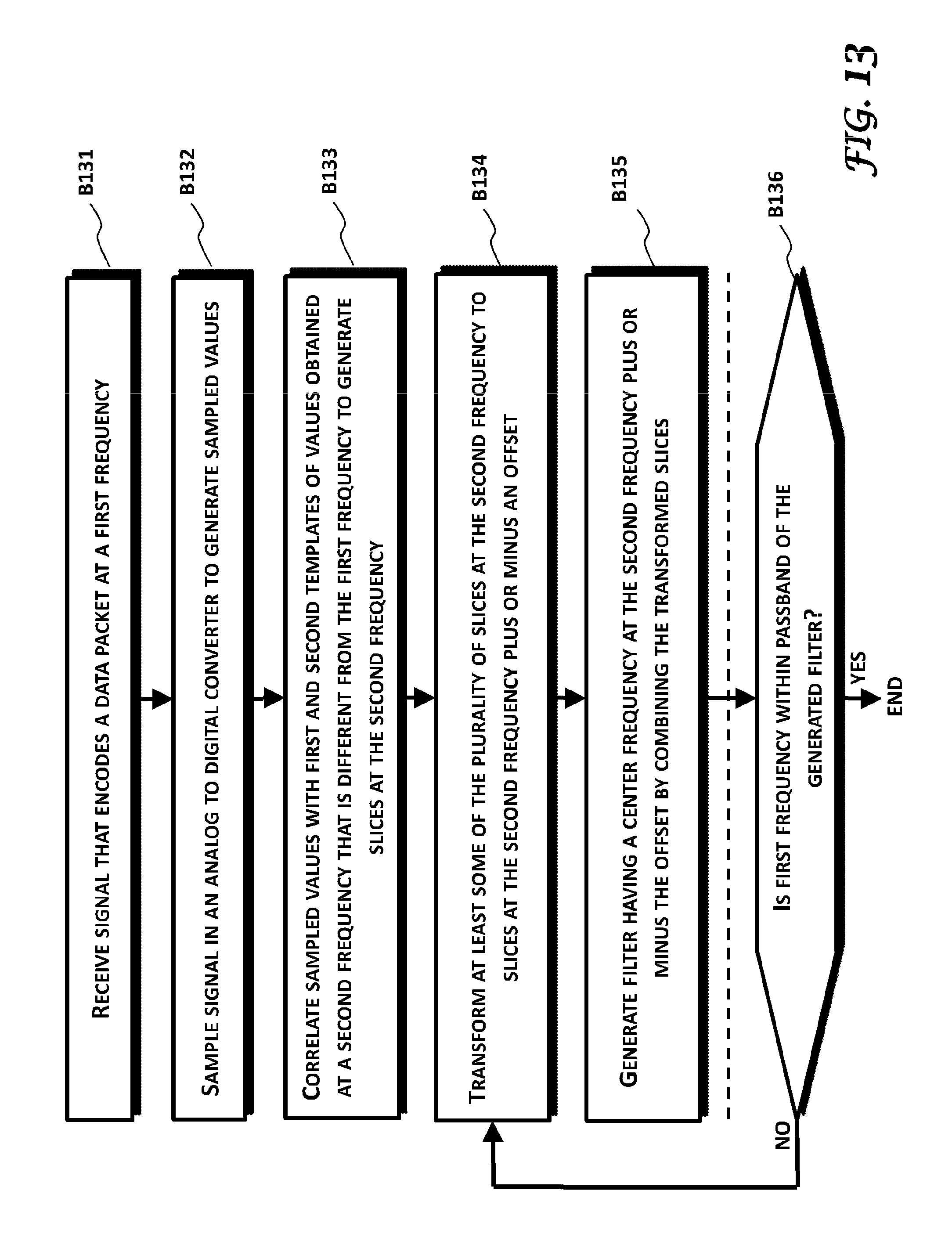
M00001

M00002

M00003

M00004

M00005

M00006

M00007

M00008

M00009

M00010

M00011

XML
uspto.report is an independent third-party trademark research tool that is not affiliated, endorsed, or sponsored by the United States Patent and Trademark Office (USPTO) or any other governmental organization. The information provided by uspto.report is based on publicly available data at the time of writing and is intended for informational purposes only.
While we strive to provide accurate and up-to-date information, we do not guarantee the accuracy, completeness, reliability, or suitability of the information displayed on this site. The use of this site is at your own risk. Any reliance you place on such information is therefore strictly at your own risk.
All official trademark data, including owner information, should be verified by visiting the official USPTO website at www.uspto.gov. This site is not intended to replace professional legal advice and should not be used as a substitute for consulting with a legal professional who is knowledgeable about trademark law.