Lid Assembly Apparatus And Methods For Substrate Processing Chambers
PANAVALAPPIL KUMARANKUTTY; Hanish Kumar ; et al.
U.S. patent application number 16/802284 was filed with the patent office on 2020-09-17 for lid assembly apparatus and methods for substrate processing chambers. The applicant listed for this patent is Applied Materials, Inc.. Invention is credited to Sumit AGARWAL, Vidyadharan Srinivasa Murthy BANGALORE, Prashant A. DESAI, Zubin HUANG, Diwakar N. KEDLAYA, Truong NGUYEN, Hanish Kumar PANAVALAPPIL KUMARANKUTTY.
| Application Number | 20200291522 16/802284 |
| Document ID | / |
| Family ID | 1000004732040 |
| Filed Date | 2020-09-17 |


View All Diagrams
| United States Patent Application | 20200291522 |
| Kind Code | A1 |
| PANAVALAPPIL KUMARANKUTTY; Hanish Kumar ; et al. | September 17, 2020 |
LID ASSEMBLY APPARATUS AND METHODS FOR SUBSTRATE PROCESSING CHAMBERS
Abstract
The present disclosure relates to a lid assembly apparatus and related methods for substrate processing chambers. In one implementation, a lid assembly includes a gas manifold. The gas manifold includes a first gas channel configured to receive a process gas, a second gas channel configured to receive a doping gas, and a third gas channel configured to receive a cleaning gas. The lid assembly also includes a showerhead. The showerhead includes one or more first gas openings that are configured to receive the process gas, and one or more second gas openings that are configured to receive the doping gas.
| Inventors: | PANAVALAPPIL KUMARANKUTTY; Hanish Kumar; (Bangalore, IN) ; DESAI; Prashant A.; (Bangalore, IN) ; KEDLAYA; Diwakar N.; (San Jose, CA) ; AGARWAL; Sumit; (Dublin, CA) ; BANGALORE; Vidyadharan Srinivasa Murthy; (Bengaluru, IN) ; NGUYEN; Truong; (Milpitas, CA) ; HUANG; Zubin; (Santa Clara, CA) | ||||||||||
| Applicant: |
|
||||||||||
|---|---|---|---|---|---|---|---|---|---|---|---|
| Family ID: | 1000004732040 | ||||||||||
| Appl. No.: | 16/802284 | ||||||||||
| Filed: | February 26, 2020 |
| Current U.S. Class: | 1/1 |
| Current CPC Class: | C23C 16/45574 20130101; C23C 16/45565 20130101 |
| International Class: | C23C 16/455 20060101 C23C016/455 |
Foreign Application Data
| Date | Code | Application Number |
|---|---|---|
| Mar 11, 2019 | IN | 201941009365 |
Claims
1. A lid assembly, comprising: a gas manifold, the gas manifold comprising: a first gas channel configured to receive a first gas defining a first gas path; a second gas channel configured to receive a second gas, defining a second gas path, the second gas path fluidly isolated from the first gas channel; and a third gas channel configured to receive a third gas, the third gas channel defining a third gas path, the third gas path in fluid communication with the first gas channel and the second gas channel; and a showerhead fluidly coupled to the gas manifold, the showerhead comprising: one or more first gas openings that are configured to receive the first gas while fluidly isolating the first gas from the second gas, and one or more second gas openings that are configured to receive the second gas while fluidly isolation the second gas from both the first gas and the third gas.
2. The lid assembly of claim 1, wherein the one or more first gas openings are disposed in one or more bosses on the showerhead, and the one or more second gas openings are disposed around or between the one or more bosses.
3. The lid assembly of claim 1, wherein the one or more first gas openings and the one or more second gas openings of the showerhead are fluidly coupled to the third gas channel.
4. The lid assembly of claim 1, further comprising a gas box comprising: a central opening coupled to a gas box third gas channel, the central opening fluidly coupled to the third gas channel; a first gas opening coupled to a gas box first gas channel, the first gas opening disposed about the central opening and fluidly coupled to the first gas channel; a second gas opening coupled to a gas box second gas channel, the second gas opening disposed about first gas opening and fluidly coupled to the second gas channel.
5. The lid assembly of claim 4, further comprising: a first plate coupled to an upper surface of the showerhead, the first plate comprising: a first plate plenum fluidly coupled to the gas box first gas channel and gas box third gas channel, defining a fourth gas path combining the first and third gas paths; a first plate second gas opening fluidly coupled to the gas box second gas channel and fluidly isolated from the plenum, further defining the second gas path.
6. The lid assembly of claim 5, further comprising: a second plate coupled to the upper surface of the showerhead and in contact with the gas box, the second plate comprising: a second plate plenum fluidly coupled to the first plate plenum, further defining the fourth gas path; a second plate third gas opening fluidly coupled to the first plate second gas opening separate from the second plate plenum, further defining the second gas path.
7. The lid assembly of claim 6, wherein the gas manifold comprises a plurality of the first gas channels, wherein the plurality of first gas channels are arranged in a radially-extended spoked configuration.
8. A lid assembly, comprising: a showerhead, comprising: a plurality of first openings formed in a central location of a first surface of the showerhead; a plurality of second openings formed in the first surface of the showerhead radially outward of the plurality of first openings, the plurality of second openings fluidly isolated from the plurality of second openings within the showerhead; and a plurality of third openings formed in the first surface of the showerhead radially outward of the plurality of first openings; and a second plate coupled to the first surface of the showerhead, the second plate comprising: a plurality of first gas openings of the second plate fluidly coupled to the plurality of first openings formed in the showerhead; first ; and a plurality of second gas opening of the second plate fluidly coupled to the plurality of second gas openings formed in the first surface of the showerhead, wherein the plurality of second gas openings of second plate are fluidly isolated from the plurality of first gas openings formed in the first surface of the showerhead.
9. The lid assembly of claim 8 further comprising: a first plate coupled to the second plate and the showerhead, the first plate comprising: a first gas opening formed in the first plate, the first gas opening fluidly coupled to a plenum formed in the second plate, the plenum fluidly coupled to the plurality of first gas openings formed in the second plate; and a second gas opening formed in the first plate, the second gas opening fluidly coupled to the plurality of second gas openings formed in the second plate.
10. The lid assembly of claim 9, further comprising: a gas box coupled to the first plate, the gas box comprising: a first gas channel of the gas box fluidly coupled to a plenum of the first plate, the plenum of the first plate fluidly coupled to plurality of first gas openings of the first plate; a second gas channel of the gas box fluidly coupled to the first plate gas opening; a gas box central opening fluidly isolated from the first gas channel of the gas box and the second gas channel of the gas box within the gas box.
11. The lid assembly of claim 10 wherein the gas box first gas channel is disposed radially outward of the gas box central opening, and the gas box second gas channel is disposed radially outward of the gas box first gas channel.
12. The lid assembly of claim 11, wherein the gas box includes a plurality of the second gas channels of the box, and the plurality of the second gas channels of the gas box are arranged in a radially-extending spoked configuration.
13. The lid assembly of claim 12, wherein the gas box includes a central opening formed therein.
14. The lid assembly of claim 13, wherein a ceramic shield is disposed in contact with the central opening of the gas box.
15. The lid assembly of claim 14, wherein the ceramic shield comprises aluminum nitride, and includes one or more openings formed in a sidewall thereof.
16. A method for delivering a plurality of gasses to a processing chamber, comprising: introducing a first gas from a first gas source into a process chamber through a first gas path formed in a lid assembly of the processing chamber; introducing a second gas from a second gas source into the processing chamber through a second gas path formed through the lid assembly of the processing chamber, the second gas path fluidly isolated from the first gas path; and introducing a third gas from a third gas source into the processing chamber through a third gas path, the third gas path in fluid communication with and overlapping with the first gas path and the second gas path.
17. The method of claim 16, wherein the first gas path includes a first channel formed through a manifold of the lid assembly, a first gas channel formed in a gas box of the lid assembly, one or more first gas openings formed in a first plate of the lid assembly, more first gas openings formed in a second plate of the lid assembly, and one or more first gas openings of a showerhead of the lid assembly.
18. The method of claim 16 wherein the second gas path includes a second channel formed through a manifold of the lid assembly, a second gas channel formed in a gas box of the lid assembly, one or more first gas openings formed in a first plate of the lid assembly, more second gas openings formed in a second plate of the lid assembly, and one or more second gas openings of a showerhead of the lid assembly.
19. The method of claim 17 wherein the third gas path overlaps with the first gas path and the second gas path in the showerhead
20. The method of claim 19 further comprising introducing a fourth gas from a fourth gas source to at least one of the first gas path, the second gas path, or the third gas path, to prevent backflow of one of the first gas, the second gas, and the third gas.
Description
BACKGROUND
Field
[0001] The present disclosure generally relates to a lid assembly apparatus and related methods for substrate processing chambers.
Description of the Related Art
[0002] Reactive gases are often used in the production of semiconductor devices. Some reactive gases, upon introduction to a chamber, will deposit a material upon substrates or sections of substrates. Certain gases break down easier and/or more quickly than other gases. For example some gases might break down easier and/or more quickly than other gases at certain temperatures. This results in inefficiency, waste, contamination, and reliability issues for substrate processing operations. For example, gases breaking down can cause reliability issues for a high-k dielectric that was deposited onto a semiconductor during substrate processing operations.
[0003] Therefore there is a need for an apparatus that delivers gases to the substrate processing chamber efficiently and reliably.
SUMMARY
[0004] The present disclosure relates to a lid assembly apparatus and related methods for substrate processing chambers.
[0005] In one implementation, a lid assembly includes a gas manifold. The gas manifold includes a first gas channel configured to receive a process gas, a second gas channel configured to receive a doping gas, and a third gas channel configured to receive a cleaning gas. The lid assembly also includes a showerhead. The showerhead includes one or more first gas openings that are configured to receive the process gas, and one or more second gas openings that are configured to receive the doping gas.
BRIEF DESCRIPTION OF THE DRAWINGS
[0006] So that the manner in which the above recited features of the present disclosure can be understood in detail, a more particular description of the disclosure, briefly summarized above, may be had by reference to embodiments, some of which are illustrated in the appended drawings. It is to be noted, however, that the appended drawings illustrate only exemplary implementations and are therefore not to be considered limiting of its scope, and may admit to other equally effective implementations.
[0007] FIG. 1 is a schematic illustration of a substrate processing chamber, according to one implementation of the present disclosure.
[0008] FIG. 2A is a schematic illustration of a lid assembly, according to one implementation of the present disclosure.
[0009] FIG. 2B is an enlarged partial illustration of the lid assembly illustrated in FIG. 2A, according to one implementation of the present disclosure.
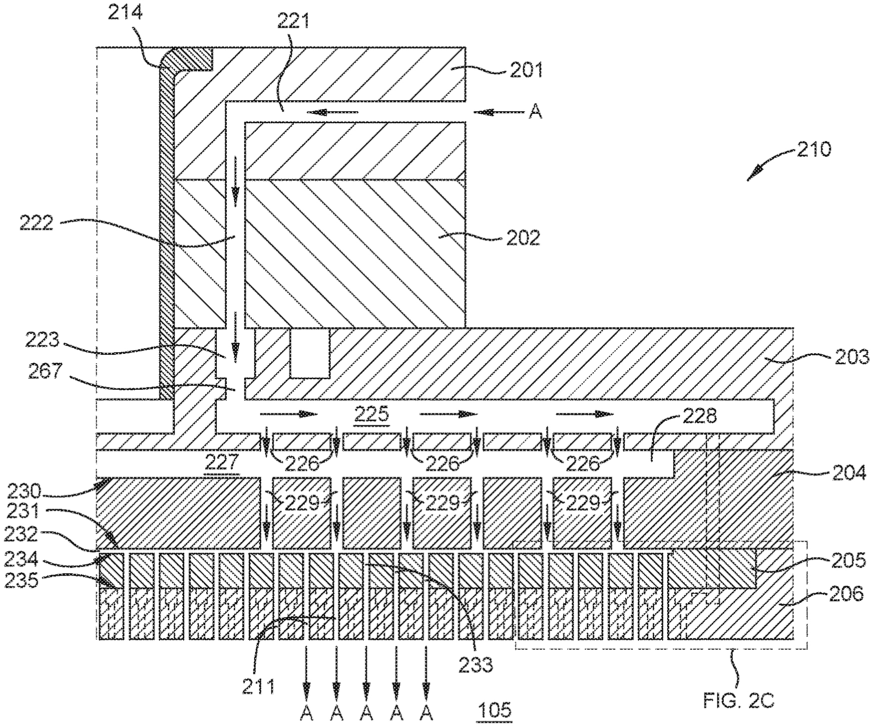
[0010] FIG. 2C is an enlarged partial illustration of the showerhead illustrated in FIG. 2B, according to one implementation of the present disclosure.
[0011] FIG. 2D is an enlarged partial illustration of the lid assembly illustrated in FIG. 2A, according to one implementation of the present disclosure.
[0012] FIG. 2E is an enlarged partial illustration of the showerhead illustrated in FIG. 2D, according to one implementation of the present disclosure.
[0013] FIG. 2F is an enlarged partial illustration of the lid assembly illustrated in FIG. 2A, according to one implementation of the present disclosure.
[0014] FIG. 2G is a schematic top-view illustration of the gas manifold illustrated in FIG. 2A, according to one implementation of the present disclosure.
[0015] FIG. 2H is a schematic top-view illustration of the gas box illustrated in FIG. 2A, according to one implementation of the present disclosure.
[0016] FIG. 2I is a schematic top-view illustration of the first plate illustrated in FIG. 2A, according to one implementation of the present disclosure.
[0017] FIG. 2J is a schematic top-view illustration of the second plate and the showerhead illustrated in FIG. 2A, according to one implementation of the present disclosure.
[0018] FIG. 2K is a schematic top-view illustration of the showerhead illustrated in FIG. 2A, according to one implementation of the present disclosure.
[0019] FIG. 2L is a partially-enlarged view of the showerhead illustrated in FIG. 2K.
[0020] To facilitate understanding, identical reference numerals have been used, where possible, to designate identical elements that are common to the figures. It is contemplated that elements and features of one embodiment may be beneficially incorporated in other embodiments without further recitation.
DETAILED DESCRIPTION
[0021] The present disclosure relates to a lid assembly apparatus and related methods for substrate processing chambers. FIG. 1 is a schematic illustration of a substrate processing chamber 104, according to one implementation of the present disclosure. The substrate processing chamber 104 includes a pedestal 108 for supporting substrates 101 thereon.
[0022] The substrate processing chamber 104 includes a lid assembly 110. The lid assembly 110 is configured to introduce precursor gases and cleaning gases into a processing volume 105 of the substrate processing chamber 104. The lid assembly 110 includes a showerhead 106 that introduces gases into the processing volume 105. The precursor gases introduced into the processing volume 105 are configured to react on or above the substrate 101 for the purposes of depositing a material onto the substrate 101. The material deposited onto the substrate 101 may include a high-k dielectric material for the purposes of producing a semiconductor. Plasma is created in the processing volume 105 to facilitate deposition of the material onto the substrate 101. The substrate processing chamber 104 includes one or more energy sources that propagate radio frequency (RF) energy, direct current (DC) voltage, and/or alternating current (AC) throughout the substrate processing chamber 104 and/or components thereof. The substrate processing chamber 104 includes one or more heaters and/or one or more cooling channels, such as in the pedestal 108, that control the temperatures of various components and aspects of the substrate processing chamber 104.
[0023] The substrate processing chamber 104 includes an exhaust opening 109. The exhaust opening 109 is fluidly connected to a vacuum pump 133. The vacuum pump 133 is configured to exhaust gases from the processing volume 105 of the substrate processing chamber 104 through the exhaust opening 109.
[0024] FIG. 2A is a schematic illustration of a lid assembly 210, according to one implementation of the present disclosure. One or more features, components, and/or aspects of the lid assembly 210 may be included in the lid assembly 110 and/or the showerhead 106 illustrated in FIG. 1.
[0025] The lid assembly 210 includes a gas manifold 201, an isolator manifold 202, a gas box 203, a first plate 204, a showerhead 206, and a second plate 205. The gas manifold 201 is configured to receive two or more precursor gases from two or more precursor gas sources, and is configured to receive one or more cleaning gases from one or more cleaning gas sources. The isolator manifold 202 is disposed under the gas manifold 201. The isolator manifold 202 is configured to electrically isolate components or aspects above the isolator manifold 202, such as the gas manifold 201, from components or aspects below the isolator manifold 202. For example, the isolator manifold is configured to electrically isolate the gas manifold 201 from one or more of RF energy, DC voltage, and/or AC current propagating throughout the processing volume 105. The gas box 203 is disposed under the gas manifold 201 and the isolator manifold 202. The first plate 204 is disposed under the gas box 203. In one example, the first plate 204 is a blocker plate. The showerhead 206 is disposed under the first plate 204. A second plate 205 is disposed between the showerhead 206 and the first plate 204. The second plate 205 is disposed within an inner shoulder 209 of the showerhead 206.
[0026] The showerhead 206 includes one or more first gas openings 211 and one or more second gas openings 213. The first gas openings 211 are configured to introduce a first gas A into a processing volume 105 (illustrated in FIG. 1). The second gas openings 213 are configured to introduce a second gas B into the processing volume 105. The first gas A enters the lid assembly 210 through the gas manifold 201 and exits the lid assembly 210 through the first gas openings 211 of the showerhead 206. The second gas B enters the lid assembly 210 through the gas manifold 201 and exits the lid assembly 210 through the second gas openings 213 of the showerhead 206.
[0027] As an example, the first gas A includes a process gas. The process gas includes one or more of silane and/or disilane. The second gas B includes a doping gas. The doping gas includes one or more of boron, phosphine, fluorine, arsenic, and/or nitrogen trifluoride. However, other gases are also contemplated.
[0028] The lid assembly 210 and the showerhead 206 are configured such that the first gas A and the second gas B are separated until the first gas A exits the showerhead 206 through the first gas openings 211 and the second gas B exits the showerhead 206 through the second gas openings 213. The first gas A and the second gas B do not mix until the first gas A and the second gas B reach the processing volume 105. These configurations allow the respective densities of the first gas A and the second gas B to be relatively high, resulting in reliable mixing of the first gas A and the second gas B in the processing volume 105 and adjacent to a substrate being processed (such as substrate 101).
[0029] These configurations also prevent or mitigate the effects of one of first gas A and second gas B completely or partially breaking down before or faster than the other of first gas A and second gas B. In an example where first gas A includes a process gas and second gas B includes a doping gas, the doping gas may break down earlier or faster than the process gas at a certain temperature. These configurations prevent or mitigate the effects of the doping gas breaking down relative to the process gas by keeping the process gas and doping gas separate until the process gas and the doping gas exit the showerhead 206 of the lid assembly 210. By separating the first gas A and the second gas B, reactions between first gas A and second gas B can be prevented until first gas A and second gas B reach the processing volume 105. As an example, reactions between first gas A and second gas B can be prevented until right above the surface of a substrate (such as the surface of substrate 101 that faces the showerhead 106 illustrated in FIG. 1). This achieves increased efficiency, less waste, and reliable deposition of films onto substrates.
[0030] The lid assembly 210 includes an insulator 214. The insulator 214 is disposed in a central opening 215 of the gas manifold 201, a central opening 216 of the isolator manifold 202, and a central opening 217 of the gas box 203. The insulator 214 includes a ceramic shield. In one example, the insulator 214 includes aluminum nitride. The insulator 214 reduces or prevents heat buildup and/or radical buildup on an inner surface 218 of the gas manifold 201, an inner surface 219 of the isolator manifold 202, and an inner surface 220 of the gas box 203. The insulator 214 includes an opening 289 that corresponds to the third gas channel 253 illustrated in FIG. 2F.
[0031] FIG. 2B is an enlarged partial illustration of the lid assembly 210 illustrated in FIG. 2A, according to one implementation of the present disclosure. The gas manifold 201 is configured to receive the first gas A through a first gas channel 221 of the gas manifold 201. The first gas channel 221 is fluidly connected to a first gas channel 222 of the isolator manifold 202. The isolator manifold 202 is configured to receive the first gas A through the first gas channel 222. The first gas channel 222 is fluidly connected to a first gas opening 223 of the gas box 203. The gas box 203 is configured to receive the first gas A through the first gas opening 223. The first gas opening 223 of the gas box 203 is fluidly connected to a first gas channel 225 of the gas box 203.
[0032] The first gas channel 225 includes one or more first gas openings 226 (six are shown) that are configured to deliver the first gas A from the first gas channel 225 and into a plenum 227 of the first plate 204. The plenum 227 is defined by a recess 228 of the first plate 204 and the gas box 203. The recess 228 defines a first surface 230 of the first plate 204. The first plate also includes a second surface 231. The first plate 204 includes one or more first gas openings 229 that extend from the first surface 230 to the second surface 231 of the first plate 204. The first gas openings 229 are fluidly connected to a plenum 232 that is between the second surface 231 of the first plate 204 and the second plate 205. The first gas openings 229 are configured to deliver first gas A from the plenum 227 and into the plenum 232 between the first plate 204 and the second plate 205.
[0033] The second plate 205 includes one or more first gas openings 233 that extend from a first surface 234 of the second plate 205 to a second surface 235 of the second plate 205. In one example, one or more of the first gas openings 229 of the first plate 204 is aligned with one or more of the first gas openings 226 of the first gas channel 225 of the gas box 203. In one example, one or more of the first gas openings 229 of the first plate 204 is aligned with one or more of the first gas openings 233 of the second plate 205.
[0034] The first gas openings 233 of the second plate 205 are configured to deliver the first gas A from the plenum 232 and into the first gas openings 211 of the showerhead 206.
[0035] FIG. 2C is an enlarged partial illustration of the showerhead 206 illustrated in FIG. 2B, according to one implementation of the present disclosure. The showerhead 206 includes one or more bosses 240 that protrude from a first surface 236 of the showerhead 206. The first gas openings 211 extend from a boss surface 237 to a second surface 238 of the showerhead 206. The second surface 238 faces the processing volume 105 and is exposed thereto. The boss surfaces 237 of the bosses 240 contact the second surface 235 of the second plate 205. In one example, one or more of the first gas openings 233 of the second plate 205 is aligned with one or more of the first gas openings 211 of the showerhead 206.
[0036] As illustrated in FIGS. 2B and 2C, the first gas channel 221 of the gas manifold 201 is fluidly connected to the showerhead 206 and the processing volume 105. The lid assembly 210 delivers the first gas A from a first gas source and into the processing volume 105.
[0037] FIG. 2D is an enlarged partial illustration of the lid assembly 210 illustrated in FIG. 2A, according to one implementation of the present disclosure. The gas manifold 201 is configured to receive the second gas B through a second gas channel 241. The second gas channel 241 is separate and distinct from the first gas channel 221 illustrated in FIG. 2B. The second gas channel 241 is configured to deliver the second gas B to a second gas channel 242 of the isolator manifold 202. The second gas channel 242 is separate and distinct from the first gas channel 222 of the isolator manifold 202. The second gas channel 242 is configured to deliver the second gas B from the second gas channel 241 of the gas manifold 201 and into a second gas opening 243 of the gas box 203. The second gas opening 243 is configured to deliver the second gas B into a second gas channel 244 of the gas box 203. The second gas opening 243 is disposed radially outward of the first gas opening 223 of the gas box 203.
[0038] The second gas channel 244 off the gas box 203 is separate and distinct from the first gas channel 25 illustrated in FIG. 2B. The second gas channel 244 includes one or more second gas openings 246. The second gas openings 246 of the second gas channel 244 are disposed radially outside of the first gas openings 226 of the first gas channel 225. The second gas openings 246 are configured to deliver the second gas B from the second gas channel 244 and into a second gas opening 247 of the first plate 204. The second gas opening 247 is disposed radially outside of the first gas openings 229 illustrated in FIG. 2B. In one example, the second gas opening 247 is aligned with the second gas opening 246 of the second gas channel 244.
[0039] The second gas opening 247 of the first plate 204 is configured to deliver the second gas B from the gas box 203 and into a second gas opening 248 of the second plate 205. In one example, the second gas opening 247 of the first plate 204 is aligned with the second gas opening 248 of the second plate 205.
[0040] FIG. 2E is a partially-enlarged illustration of the showerhead 206 illustrated in FIG. 2D, according to one implementation of the present disclosure. The second gas opening 248 of the second plate 205 is configured to deliver the second gas B from the second plate 205 and to a second gas channel 249 of the showerhead 206. The second gas opening 248 is disposed radially outside of the first gas openings 233 of the second plate 205. The second gas channel 249 is disposed radially outside of the bosses 240 and the first surface 236. A wall 250 is disposed between the first surface 236 and the second gas channel 249. The wall 250 includes one or more wall openings 251 that are configured to deliver the second gas B from the second gas channel 249 and into one or more gaps 252 that are disposed around and between the bosses 240. The second gas openings 213 of the showerhead 206 extend from the first surface 236 to the second surface 238. The second gas openings 213 are configured to deliver the second gas B from the gaps 252 and into the processing volume 105.
[0041] As illustrated in FIGS. 2D and 2E, the second gas channel 241 of the gas manifold 201 is fluidly connected to the showerhead 206 and the processing volume 105. The lid assembly 210 delivers the second gas B from a second gas source and into the processing volume 105. The lid assembly 210 keeps the flow of the first gas A separate from the flow of the second gas B until first gas A and first gas B are introduced into the processing volume 105. As an example, the boss surfaces 237 of the bosses 240 contact the second surface 235 and seal thereagainst. The bosses 240 thus fluidly separate the first gas A flowing through the first gas openings 211 from the second gas B flowing through the gaps 252 and the second gas openings 213.
[0042] By keeping first gas A separate from second gas B, the lid assembly 210 facilitates mixing first gas A and second gas B in the processing volume 105 near the substrate 101 (illustrated in FIG. 1). Mixing the first gas A and second gas B in the processing volume 105 facilitates reliable and efficient deposition of films onto the substrate 101. The first gas A and second gas B do not mix prior to entering the processing volume 105, mitigating or eliminating the effects of one or first gas A or second gas B breaking down relative to the other of first gas A or second gas B. For example, reducing the amount of a reactant gas that is broken down ensures that the reactant gas reaches the processing volume 105 at a density that facilitates mixing with another reactant gas to deposit a film onto a substrate.
[0043] FIG. 2F is a partially-enlarged illustration of the lid assembly 210 illustrated in FIG. 2A, according to one implementation of the present disclosure. The gas manifold 201 is configured to receive a third gas C into a third gas channel 253. The third gas channel 253 is separate and distinct from the first gas channel 221 and the second gas channel 241. The gas manifold 201 receives the third gas C from a third gas source. The third gas C is a cleaning gas, which may be activated by a remote plasma source (RPS) prior to introduction to the third gas channel 253. In one example, the third gas C includes one or more carrier and/or cleaning gases such as argon, nitrogen trifluoride, and/or oxygen.
[0044] The third gas C can also be received by the gas manifold 201 into the central opening 215 from a third gas source that is above the central opening 215. In one example, the third gas C that is received by the third gas channel 253 bypasses an RPS and is not activated by the RPS, and the third gas C received by the central opening 215 passes through and is activated by the RPS.
[0045] The third gas channel 253 is configured to deliver the third gas C into the central opening 215 of the gas manifold 201, the central opening 216 of the isolator manifold 202, and the central opening 217 of the gas box 203. The gas box 203 is configured to deliver the third gas C from the central opening 217 and into a third gas channel 254 of the gas box 203. The lid assembly 210 is hence configured such that the third gas C bypasses the isolator manifold 202, the first gas opening 223 of the gas box 203, and the second gas opening 243 of the gas box 203. These configurations allow for a simple design of the gas box 203 and for large flow rates of third gas C to flow through the central opening 215 of the gas manifold 201.
[0046] The third gas channel 254 of the gas box 203 is separate and distinct from the first gas channel 225 and the second gas channel 244. The third gas channel 254 includes one or more first openings 255 that are configured to deliver the third gas C from the second gas channel 244 and into the plenum 227 between the gas box 203 and the first plate 204.
[0047] The third gas channel 254 includes one or more second openings 256 that are disposed radially outside of the first openings 255. The second openings 256 are configured to deliver the third gas C from the third gas channel 254 and into a third gas opening 262 of the first plate 204. The third gas opening 262 is separate and distinct from the second gas opening 247 of the first plate 204. In one example, the third gas opening 262 is aligned with one or more of the second openings 256 of the third gas channel 254.
[0048] One or more purge gases may be flowed through the lid assembly 210 to prevent backflow of the first gas A, second gas B, and/or the third gas C. As an example, purge gas may be flowed to prevent fluid (such as first gas A) from flowing from the plenum 227 and into the third gas channel 254. As another example, purge gas may be flowed to prevent fluid (such as second gas B) from flowing from the second gas channel 249 and into the third gas openings 263. The present disclosure also contemplates that the lid assembly 210 may include one or more valves to prevent backflow. As an example, one or more of each of the first openings 255, first gas openings 226, second gas openings 246, third gas openings 263, and/or third gas openings 262 may include valves. In one example, the valves include check valves or some other valve.
[0049] The first plate 204 is configured to deliver the third gas C from the plenum 227 and into one or more first gas openings 229. The first gas openings 229 are configured to deliver the third gas C from the plenum 227 and into the plenum 232 between the first plate 204 and the second plate 205. One or more first gas openings 233 of the second plate 205 are configured to deliver the third gas C from the plenum 232 and into the first gas openings 211 of the showerhead 206. The first gas openings 211 are configured to introduce the third gas C into the processing volume 105.
[0050] The third gas opening 262 of the first plate 204 is configured to deliver the third gas C into a third gas opening 263 of the second plate 205. The third gas opening 263 is separate and distinct from the second gas opening 248 of the second plate 205. The third gas opening 263 is configured to deliver the third gas C into the second gas channel 249 of the showerhead 206. In one example, the third gas opening 263 of the second plate 205 is aligned with the third gas opening 262 of the first plate 204.
[0051] The showerhead 206 is configured to deliver the third gas C, from the second gas channel 249, and through one or more wall openings 251 of the wall 250 and into the gaps 252 disposed between and around the bosses 240 of the showerhead 206. The showerhead is configured to deliver the third gas C from the gaps 252 and into the processing volume 105 through the one or more second gas openings 213.
[0052] Hence, the lid assembly 210 is configured to deliver the third gas C through flow paths that the first gas A and the second gas B flow through, respectively, in the first plate 204, second plate 205, and the showerhead 206. In examples where the third gas C is a cleaning gas, the lid assembly 210 can effectively, efficiently, and simultaneously clean the fluid paths for first gas A and second gas B. The lid assembly 210 can keep the flow paths for first gas A and second gas B separate prior to mixing the first gas A and the second gas B in the processing volume 105. The lid assembly 210 can also clean fluid paths for first gas A and second gas B simultaneously.
[0053] FIG. 2G is a schematic top-view illustration of the gas manifold 201 illustrated in FIG. 2A, according to one implementation of the present disclosure. The gas manifold 201 includes a shoulder 264 disposed adjacent to the central opening 215. The shoulder 264 supports the insulator 214 illustrated in FIG. 2A. The first gas channel 221, second gas channel 241, and third gas channel 253 are separate and distinct, and are disposed in a spaced-apart relation from each other in the gas manifold 201. The first gas channel 221 runs from an outer surface 268 of the gas manifold 201 to a bottom surface 266 of the gas manifold 201. The second gas channel 241 runs from the outer surface 268 of the gas manifold 201 to the bottom surface 266 of the gas manifold 201. The third gas channel 253 runs from the outer surface 268 to the inner surface 218 of the gas manifold 201.
[0054] FIG. 2H is a schematic top-view illustration of the gas box 203 illustrated in FIG. 2A, according to one implementation of the present disclosure. The gas box 203 includes first gas channels 225, second gas channels 244, and third gas channels 254 that are separate and distinct. The first gas channels 225, second gas channels 244, and third gas channels 254 are disposed at a spaced-apart relation from each other in an alternating arrangement. One or more of each of the first gas channels 225, second gas channels 244, and/or third gas channels 254 may be disposed in different vertical planes in the gas box 203. In the implementation illustrated in FIG. 2F, the third gas channel 254 is disposed vertically below the first gas channel 225 illustrated in FIG. 2B and the second gas channel 244 illustrated in FIG. 2D. The present disclosure also contemplates that one or more of each of the first gas channels 225, second gas channels 244, and/or third gas channels 254 may be disposed in the same vertical plane in the gas box 203. In the implementation illustrated in FIG. 2D, the second gas channel 244 is disposed in the same vertical plane as the first gas channel 225.
[0055] The first gas channels 225 each include one or more first gas openings 226 arranged in a linear arrangement extending radially outward. The second gas channels 244 each include one or more second gas openings 246 that are disposed radially outside of the first gas openings 226 of the first gas channels 225. The third gas channels 254 each include one or more first openings 255 and one or more second openings 256 arranged in a linear arrangement extending radially outward. The second openings 256 are disposed radially outside of the first openings 255 and the first gas openings 226 of the first gas channels 225.
[0056] The first gas opening 223 is disposed circumferentially about the central opening 217 of the gas box 203, and radially outside of the central opening 217. The first gas opening 223 includes one or more first gas ports 267 that are configured to deliver first gas A from the first gas opening 223 and into the first gas channels 225.
[0057] The second gas opening 243 is disposed circumferentially about the first gas opening 223 of the gas box 203, and radially outside of the first gas opening 223. The second gas opening 243 includes one or more second gas ports 269 that are configured to deliver second gas B from the second gas opening 243 and into the second gas channels 244.
[0058] The third gas channels 254 are open to the central opening 217 of the gas box 203. The gas box 203 is configured to deliver the third gas C from the central opening 217 and into the third gas channels 254.
[0059] FIG. 2I is a schematic top-view illustration of the first plate 204 illustrated in FIG. 2A, according to one implementation of the present disclosure. In one example, the first plate 204 is a blocker plate. The first gas openings 229 are disposed in a concentric circular pattern on the first plate 204, as illustrated in FIG. 2I. The first plate 204 includes second gas openings 247 and third gas openings 262 disposed circumferentially on the first plate 204 in an alternating arrangement. The second gas openings 247 and the third gas openings 262 are disposed radially outside of the first gas openings 229. The second gas openings 247 are oblong in shape. The third gas openings 262 and the first gas openings 229 are circular in shape. Each of the second gas openings 247 corresponds to a second gas opening 246 of a second gas channel 244 of the gas box 203. Each of the third gas openings 262 corresponds to a second opening 256 of a third gas channel 254 of the gas box 203. The second gas openings 247 and third gas openings 262 are disposed in first bosses 298 and second bosses 299, respectively. The first bosses 298 and second bosses 299 protrude from the first plate 204. The first plate 204 includes an inner shoulder 297 and an outer shoulder 296.
[0060] FIG. 2J is a schematic top-view illustration of the second plate 205 and the showerhead 206 illustrated in FIG. 2A, according to one implementation of the present disclosure. The second plate 205 is disposed within the inner shoulder 209 of the showerhead 206. The first gas openings 233 are disposed in a hexagonal pattern on the second plate 205, as illustrated in FIG. 2J. Second gas openings 248 and third gas openings 263 are disposed circumferentially on the second plate 205 in an alternating arrangement. The second gas openings 248 and the third gas openings 263 are disposed radially outside of the first gas openings 233. The second gas openings 248 are oblong in shape. The first gas openings 233 and the third gas openings 263 are circular in shape. The second gas openings 248 correspond to the second gas openings 247 of the first plate 204. The third gas openings 263 correspond to the third gas openings 262 of the first plate 204. The second gas openings 248 and the third gas openings 263 are disposed in first bosses 290 and second bosses 291, respectively. The first bosses 290 and the second bosses 291 protrude from the second plate 205.
[0061] The present disclosure contemplates that the ports, openings, and/or channels disclosed herein may be a variety of shapes, such as circular or oblong. The shapes of the ports, openings, and/or channels may be used to accommodate various flow rates of the first gas A, second gas B, and/or third gas C, and may be used to facilitate producing seals between components or features of lid assembly 210. As an example, the second gas openings 247 of the first plate 204 are illustrated as oblong in shape in FIG. 2I to accommodate various flow rates of second gas B. The oblong shape of second gas openings 247 may be used to increase the cross-sectional areas of second gas openings 247 to facilitate accommodation of increased flow rates of second gas B. The oblong shape of second gas openings 247 can facilitate accommodation of increased flow rates of second gas B without the first bosses 298 interfering with a seal between the outer shoulder 296 and the inner shoulder 297. The oblong shape of the second gas openings 247 also facilitates producing a seal between one or more aspects of gas box 203 and one or more aspects of first plate 204, such as to prevent second gas B from flowing into the plenum 227.
[0062] The shapes and sizes of the openings, channels, and/or ports disclosed herein may be modified based on process requirements for the substrate 101, substrate processing chamber 104, first gas A, second gas B, and/or third gas C.
[0063] FIG. 2K is a schematic top-view illustration of the showerhead 206 illustrated in FIG. 2A, according to one implementation of the present disclosure. The showerhead 206 includes the second gas channel 249 disposed circumferentially around the first gas openings 211, bosses 240, and second gas openings 213. The second gas openings 213 are disposed around and between the bosses 240. The second gas openings 213 are separated from the second gas channel 249 by the wall 250. Wall openings 251 allow the second gas B to flow from the second gas channel 249 to the second gas openings 213.
[0064] In one example, the bosses 240 and the first gas openings 211 are disposed in a hexagonal arrangement on the showerhead 206, as illustrated in FIG. 2K.
[0065] FIG. 2L is a partially-enlarged view of the showerhead 206 illustrated in FIG. 2K. The bosses 240 are disposed at a density such that respective centers of the bosses 240 are disposed at a distance L from each other. In one example, the distance L is within a range of about 0.0 inches to about 0.7 inches, such as about 0.34 inches to about 0.63 inches, such as about 0.34 inches or about 0.63 inches.
[0066] Although the present disclosure illustrates openings, ports, and channels in various orientations and configurations, the present disclosure contemplates that other orientations and/or configurations are possible. For example, the present disclosure contemplates that the plates, showerhead, manifolds, gas box, openings, ports, and/or channels disclosed herein can involve various shapes, sizes, numbers of iterations, lengths, dimensions, vertical orientations, horizontal orientations, and/or angled orientations. As an example, the number of second gas openings 213 on the showerhead 206 can be varied. The second gas openings 213 can also be disposed at various angles or can vary in shape, length, and/or size.
[0067] The present disclosure also contemplates that the first gas A, second gas B, and third gas C may be flowed through the lid assembly 210 and/or into the processing volume 105 at various specified temperatures, pressures, flow rates, and/or molecular weights.
[0068] Benefits of the present disclosure include keeping gases separate until they reach a processing volume; mixing reactant gases above a substrate; high density mixing of gases; simultaneously cleaning separate flow paths; reliable and efficient deposition of a material onto a substrate, and reducing or preventing heat buildup and/or radical buildup on a lid assembly.
[0069] Aspects of the present disclosure include a lid assembly that separates gases prior to introducing the gases into a processing volume; a gas manifold with a first gas channel, a second gas channel, and a third gas channel; a gas box; a showerhead with first gas openings, second gas openings, bosses, and gaps; and an insulator.
[0070] It is contemplated that one or more of these aspects disclosed herein may be combined. Moreover, it is contemplated that one or more of these aspects may include some or all of the aforementioned benefits.
[0071] While the foregoing is directed to embodiments of the present disclosure, other and further embodiments of the disclosure may be devised without departing from the basic scope thereof. The present disclosure also contemplates that one or more aspects of the embodiments described herein may be substituted in for one or more of the other aspects described. The scope of the disclosure is determined by the claims that follow.
* * * * *
D00000
D00001
D00002
D00003
D00004
D00005
D00006
D00007
D00008
D00009
D00010
D00011
D00012

XML
uspto.report is an independent third-party trademark research tool that is not affiliated, endorsed, or sponsored by the United States Patent and Trademark Office (USPTO) or any other governmental organization. The information provided by uspto.report is based on publicly available data at the time of writing and is intended for informational purposes only.
While we strive to provide accurate and up-to-date information, we do not guarantee the accuracy, completeness, reliability, or suitability of the information displayed on this site. The use of this site is at your own risk. Any reliance you place on such information is therefore strictly at your own risk.
All official trademark data, including owner information, should be verified by visiting the official USPTO website at www.uspto.gov. This site is not intended to replace professional legal advice and should not be used as a substitute for consulting with a legal professional who is knowledgeable about trademark law.