Earphone accessory
Jossem , et al. January 26, 2
U.S. patent number D908,666 [Application Number D/690,179] was granted by the patent office on 2021-01-26 for earphone accessory. This patent grant is currently assigned to Human, Incorporated. The grantee listed for this patent is Human, Incorporated. Invention is credited to Adam Abraham Jossem, Ferdinand Ygona Laurino, Lea Martin, Francesca Alyssum Quaglia, Benjamin S. Willis.


View All Diagrams
| United States Patent | D908,666 |
| Jossem , et al. | January 26, 2021 |
Earphone accessory
Claims
CLAIM The ornamental design for an earphone accessory substantially, as shown and described.
| Inventors: | Jossem; Adam Abraham (Seattle, WA), Martin; Lea (Seattle, WA), Quaglia; Francesca Alyssum (Seattle, WA), Laurino; Ferdinand Ygona (Seattle, WA), Willis; Benjamin S. (Bellevue, WA) | ||||||||||
|---|---|---|---|---|---|---|---|---|---|---|---|
| Applicant: |
|
||||||||||
| Assignee: | Human, Incorporated (Seattle,
WA) |
||||||||||
| Appl. No.: | D/690,179 | ||||||||||
| Filed: | May 6, 2019 |
| Current U.S. Class: | D14/223; D14/205 |
| Current International Class: | 1401 |
| Field of Search: | ;D14/223,205 ;D29/112 ;2/209,459,15,181.6,181,DIG.11,425,423,421 ;D2/639,856,947,961 ;D4/137 ;D32/40,57 ;D6/595,596,601,606,611,615,621 ;5/639,636 ;D16/330 ;604/294 ;128/858,132 ;267/145 ;297/DIG.1,452.47 ;379/452,419,451 ;55/522 ;181/129 ;381/371,374 |
References Cited [Referenced By]
U.S. Patent Documents
| 1156767 | October 1915 | Farrar |
| 1916693 | July 1933 | Scribner |
| 2234506 | March 1941 | Sistig |
| 2319690 | May 1943 | Karpen |
| 2336940 | December 1943 | Krantz |
| 2572638 | October 1951 | Loos |
| 2572947 | October 1951 | Pevney |
| 2677318 | May 1954 | Torudd |
| 2717434 | September 1955 | Duell |
| 2800165 | July 1957 | Talalay |
| 2826244 | March 1958 | Hurley |
| 2880428 | April 1959 | Forsland |
| 2971065 | February 1961 | Busse |
| 3400413 | September 1968 | La Grossa |
| 3525103 | August 1970 | Yonan |
| 3811144 | May 1974 | Yamanka |
| D241700 | October 1976 | Wattle |
| 4523661 | June 1985 | Scalzo |
| 4570038 | February 1986 | Tinelli |
| 4944040 | July 1990 | Riedel |
| D375258 | November 1996 | Weder |
| D390564 | February 1998 | Savona |
| D407640 | April 1999 | Nelson |
| D445673 | July 2001 | Richardson |
| 6474585 | November 2002 | Liao |
| D468723 | January 2003 | Pham |
| D547176 | July 2007 | Sansoldo |
| D606970 | December 2009 | Semcken |
| 7865974 | January 2011 | Heller |
| D656366 | March 2012 | Abrams |
| 8150090 | April 2012 | Ito |
| 8358799 | January 2013 | Gresko |
| D739842 | September 2015 | Birger |
| D771414 | November 2016 | Krishtul |
| D814445 | April 2018 | Willis |
| D814457 | April 2018 | Willis |
| D815065 | April 2018 | Willis |
| D822007 | July 2018 | Willis |
| D857667 | August 2019 | Willis |
| D860972 | September 2019 | Minarsch |
| D886802 | June 2020 | Willis |
| 2005/0220318 | October 2005 | Han |
| 2008/0263749 | October 2008 | Leong |
Attorney, Agent or Firm: Seed IP Law Group LLP
Description
FIG. 1 is an isometric view of an earphone accessory from a first perspective, showing an embodiment of our new design attached to an earphone for a left ear.
FIG. 2 is an isometric view thereof from a second perspective.
FIG. 3 is an isometric view of the earphone accessory from the first perspective showing the earphone accessory detached from the earphone for the left ear.
FIG. 4 is an isometric view thereof from the second perspective.
FIG. 5 is a front view thereof.
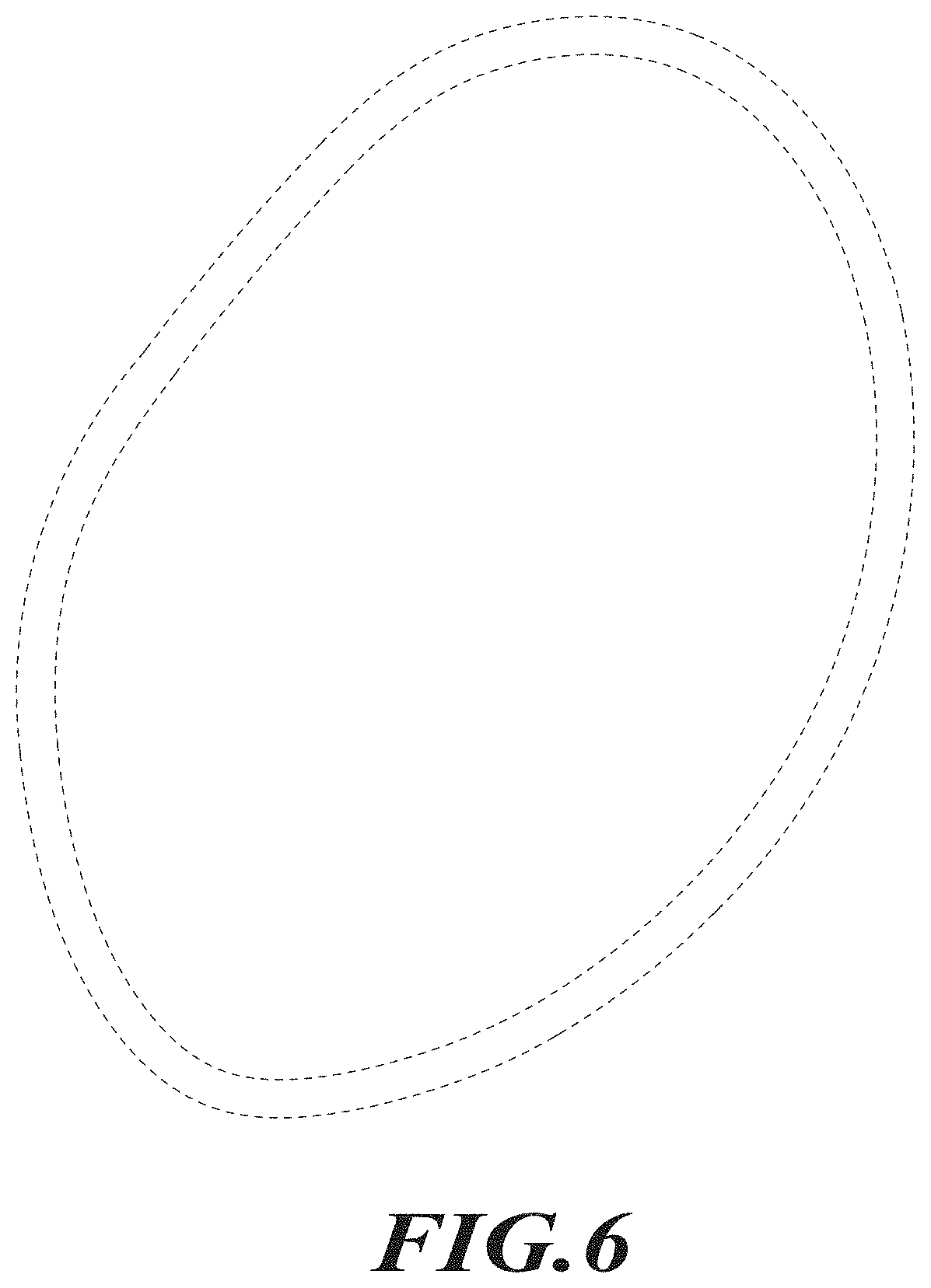
FIG. 6 is a rear view thereof.
FIG. 7 is a left side view thereof.
FIG. 8 is a right side view thereof.
FIG. 9 is a top view thereof.
FIG. 10 is a bottom view thereof.
Another embodiment for a right ear is provided, which is a mirror image of the embodiment for the left ear shown in FIGS. 1 through 10.
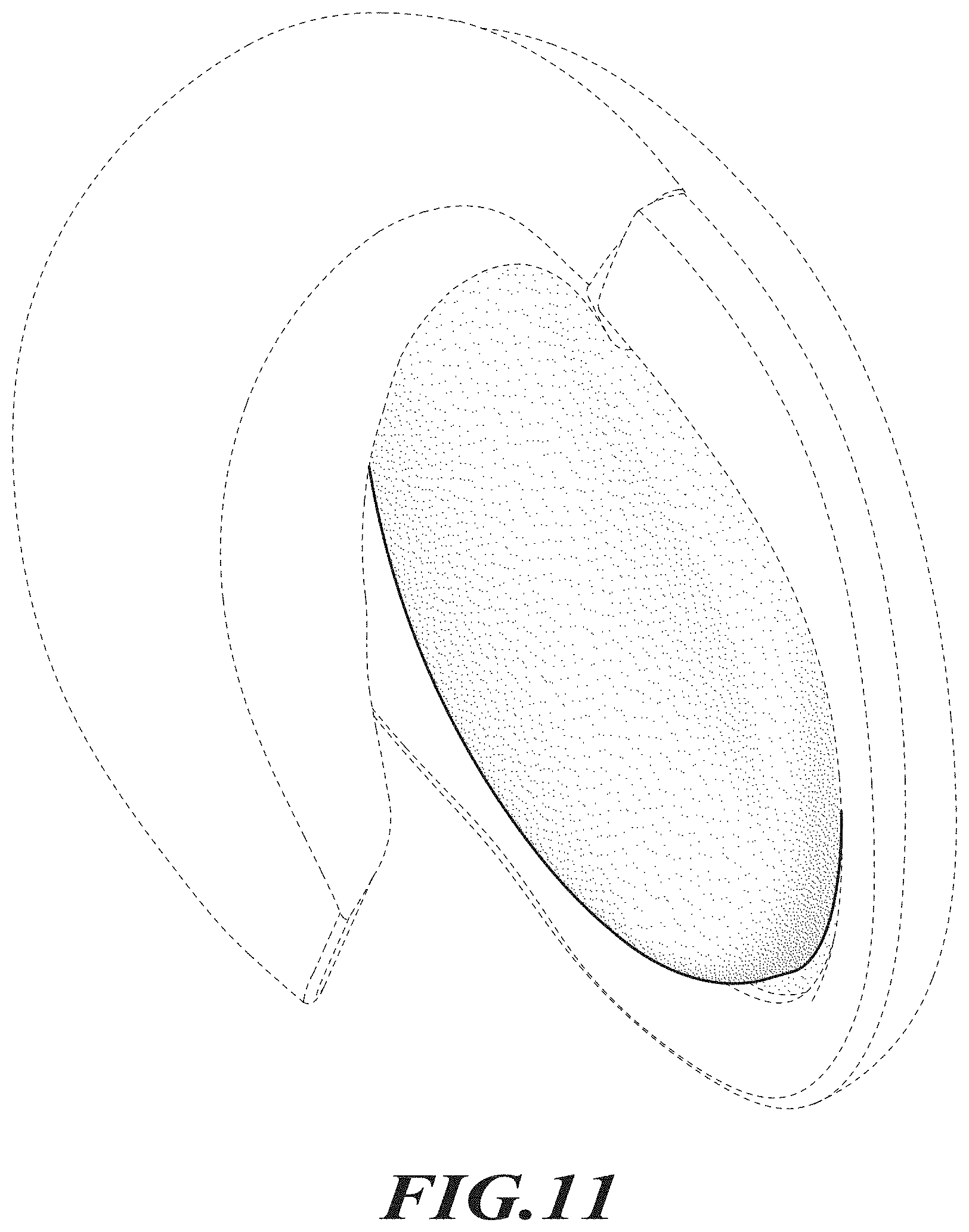
FIG. 11 is an isometric view of an earphone accessory from a first perspective, showing another embodiment of our new design attached to an earphone for the left ear.
FIG. 12 is an isometric view thereof from a second perspective.
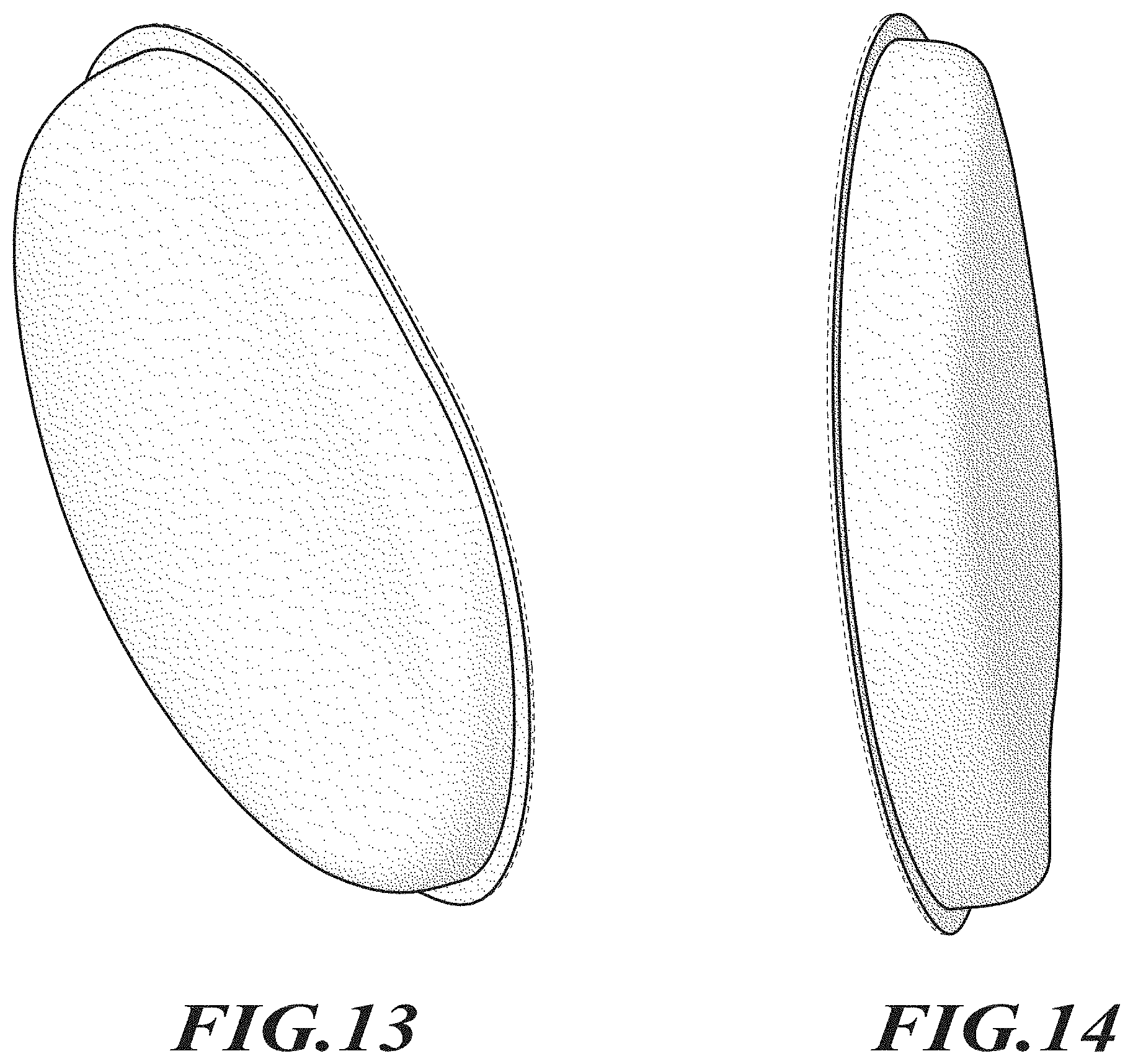
FIG. 13 is an isometric view of the earphone accessory from the first perspective showing the earphone accessory detached from the earphone for the left ear.
FIG. 14 is an isometric view thereof from the second perspective.
FIG. 15 is a front view thereof.
FIG. 16 is a rear view thereof.
FIG. 17 is a left side view thereof.
FIG. 18 is a right side view thereof.
FIG. 19 is a top view thereof; and,
FIG. 20 is a bottom view thereof.
Another embodiment for a right ear is provided, which is a mirror image of the embodiment for the left ear shown in FIGS. 11 through 20.
Stippling in the drawings represent the three-dimensional contours of the design, and are not intended to indicate surface decoration. The broken lines shown in the drawings depict environment and portions of the earphone accessory that form no part of the claimed design.
* * * * *
D00000
D00001
D00002
D00003
D00004
D00005
D00006
D00007
D00008
D00009
D00010
D00011
D00012

XML
uspto.report is an independent third-party trademark research tool that is not affiliated, endorsed, or sponsored by the United States Patent and Trademark Office (USPTO) or any other governmental organization. The information provided by uspto.report is based on publicly available data at the time of writing and is intended for informational purposes only.
While we strive to provide accurate and up-to-date information, we do not guarantee the accuracy, completeness, reliability, or suitability of the information displayed on this site. The use of this site is at your own risk. Any reliance you place on such information is therefore strictly at your own risk.
All official trademark data, including owner information, should be verified by visiting the official USPTO website at www.uspto.gov. This site is not intended to replace professional legal advice and should not be used as a substitute for consulting with a legal professional who is knowledgeable about trademark law.