Fender for work vehicle
Bering , et al.
U.S. patent number D891,336 [Application Number D/680,650] was granted by the patent office on 2020-07-28 for fender for work vehicle. This patent grant is currently assigned to DEERE & COMPANY. The grantee listed for this patent is Deere & Company. Invention is credited to Amol Adsul, Christopher A. Bering, Joshua J. Kappelman, Jeremy P. L'Heureux.


View All Diagrams
| United States Patent | D891,336 |
| Bering , et al. | July 28, 2020 |
| **Please see images for: ( Certificate of Correction ) ** |
Fender for work vehicle
Claims
CLAIM The ornamental design for a fender for work vehicle, as shown and described.
| Inventors: | Bering; Christopher A. (Dike, IA), Kappelman; Joshua J. (Cedar Falls, IA), Adsul; Amol (Pune, IN), L'Heureux; Jeremy P. (Cedar Falls, IA) | ||||||||||
|---|---|---|---|---|---|---|---|---|---|---|---|
| Applicant: |
|
||||||||||
| Assignee: | DEERE & COMPANY (Moline,
IL) |
||||||||||
| Appl. No.: | D/680,650 | ||||||||||
| Filed: | February 19, 2019 |
| Current U.S. Class: | D12/184 |
| Current International Class: | 1216 |
| Field of Search: | ;D12/90-93,96,163,164,171,181,184,196 |
References Cited [Referenced By]
U.S. Patent Documents
| D344059 | February 1994 | DeBraal |
| D347614 | June 1994 | DeBraal |
| D545255 | June 2007 | Angelo |
| D621756 | August 2010 | Angelo |
| D623103 | September 2010 | Braga |
| D699650 | February 2014 | Peltola |
| D699651 | February 2014 | Peltola |
| D712324 | September 2014 | McFarlin |
| D778795 | February 2017 | Johns |
| D839806 | February 2019 | Chi |
| D855519 | August 2019 | Bundy |
| D863159 | October 2019 | Goodrich |
| D870620 | December 2019 | Hallgren |
Other References
|
John Deere, 9R/9RT/9RX Series Tractors Brochure, "The New Power of Choice", Sep. 2017. cited by applicant. |
Primary Examiner: Kirschbaum; George D.
Assistant Examiner: Kukella; Joseph J
Attorney, Agent or Firm: Klintworth & Rozenblat IP LLP
Description
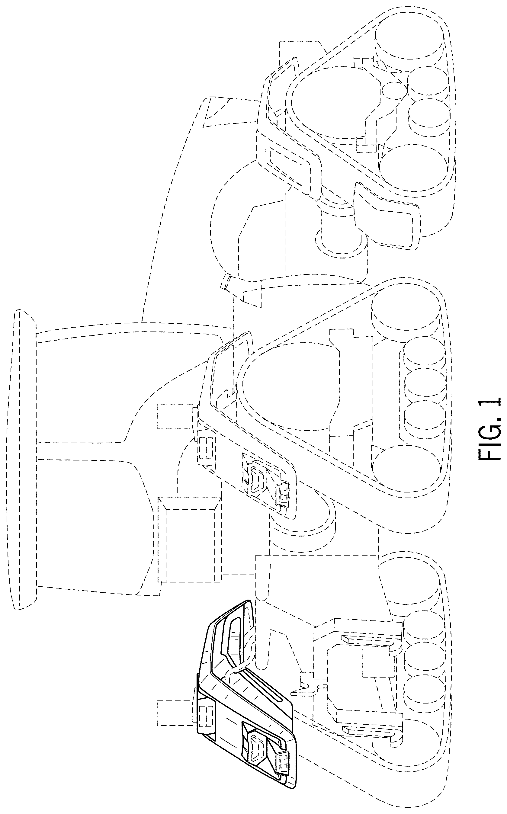
FIG. 1 is a rear perspective view of a fender for work vehicle according to one embodiment of our new design;
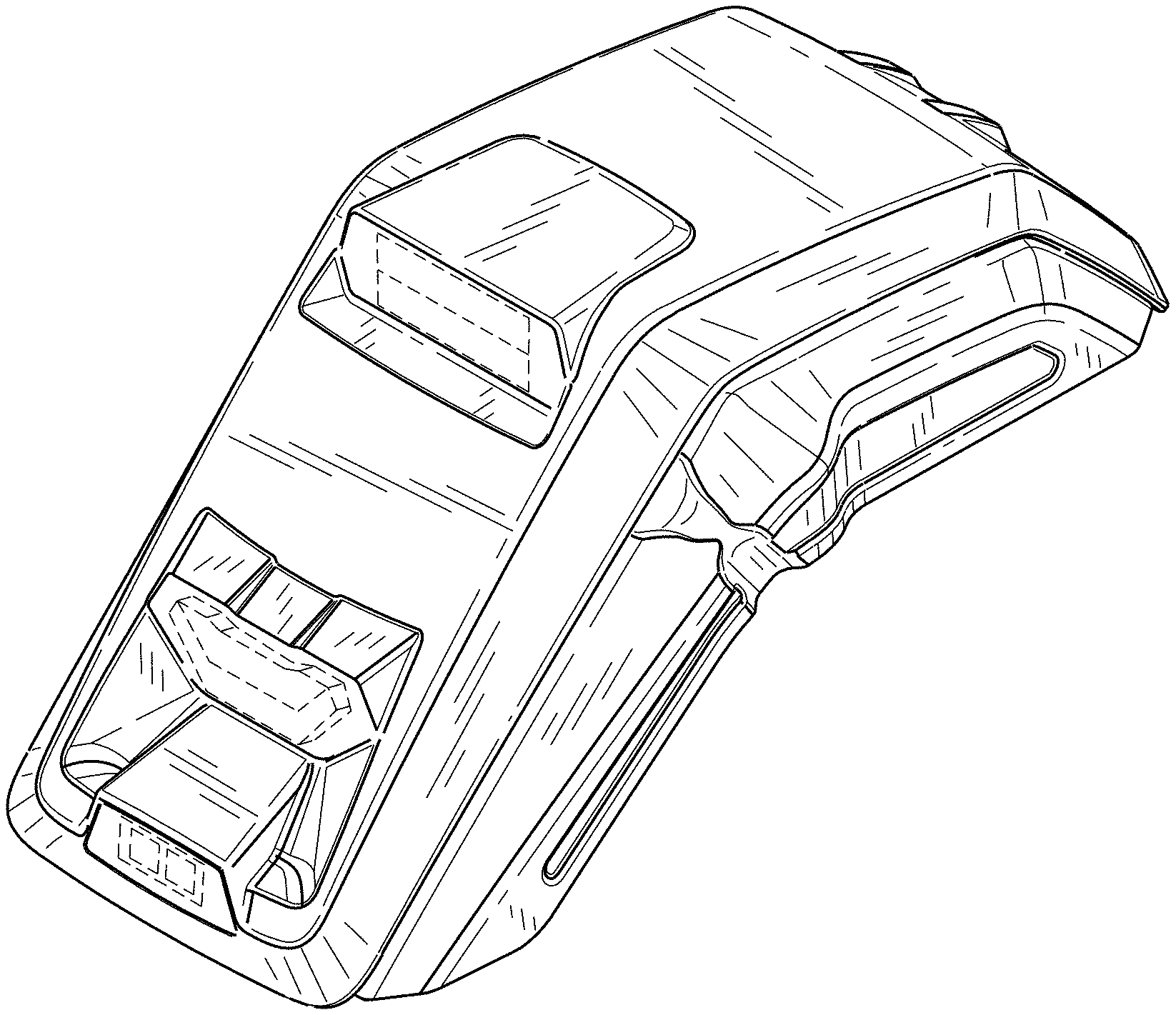
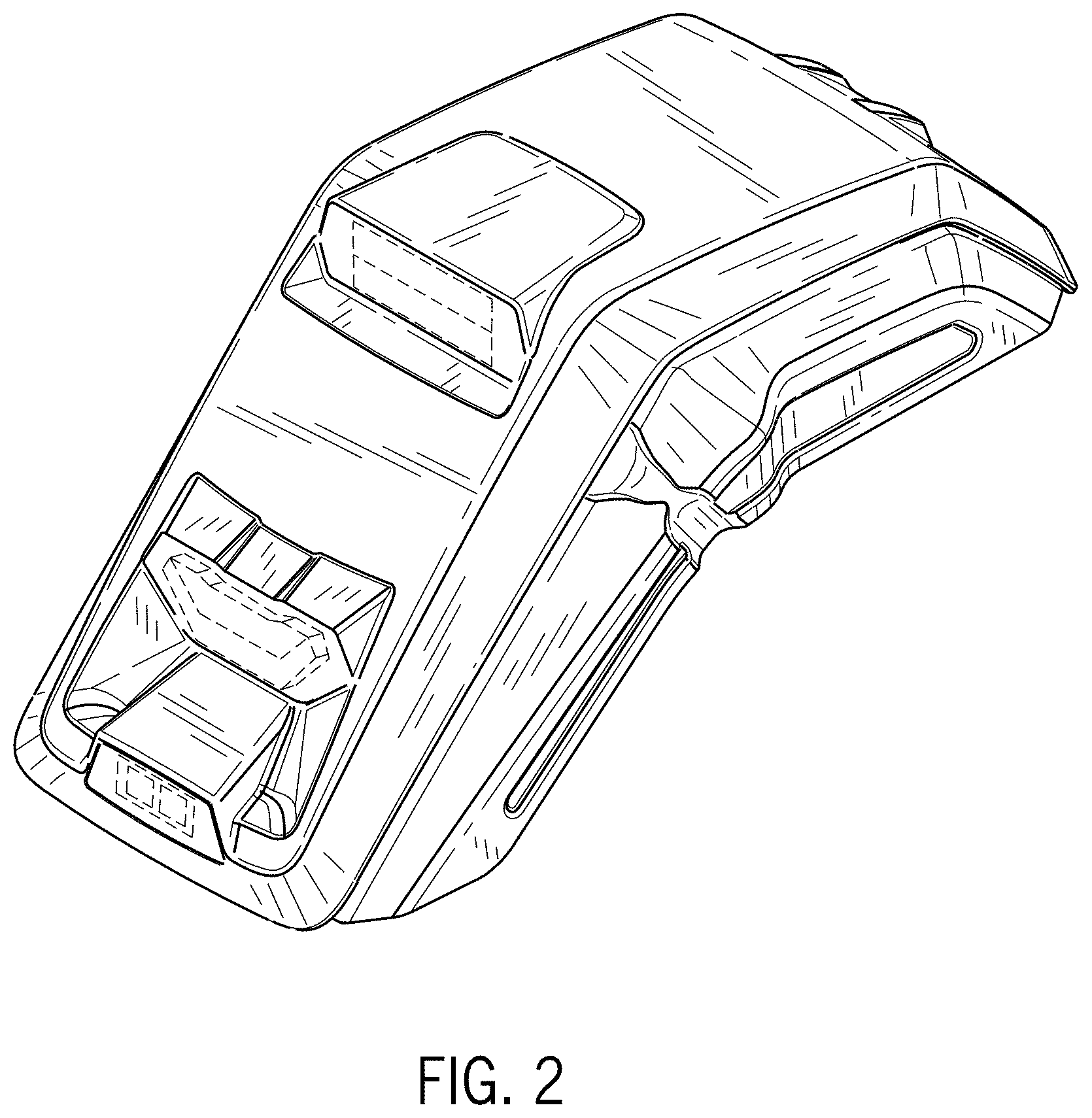
FIG. 2 is an enlarged rear perspective view thereof;
FIG. 3 is a front elevation view thereof;
FIG. 4 is a rear elevation view thereof;
FIG. 5 is a first side elevation view thereof;
FIG. 6 is a second side elevation view thereof;
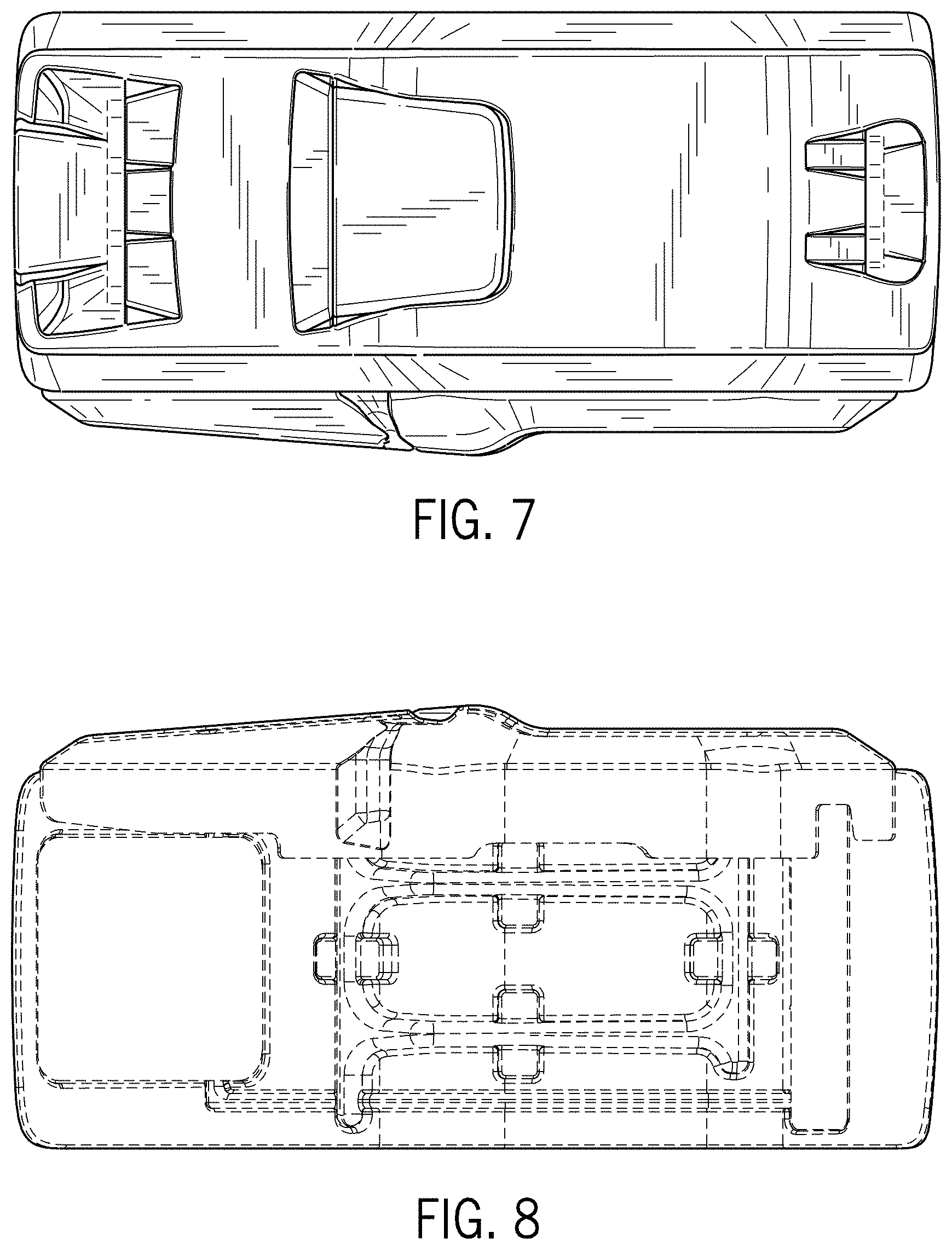
FIG. 7 is a top plan view thereof;
FIG. 8 is a bottom plan view thereof;
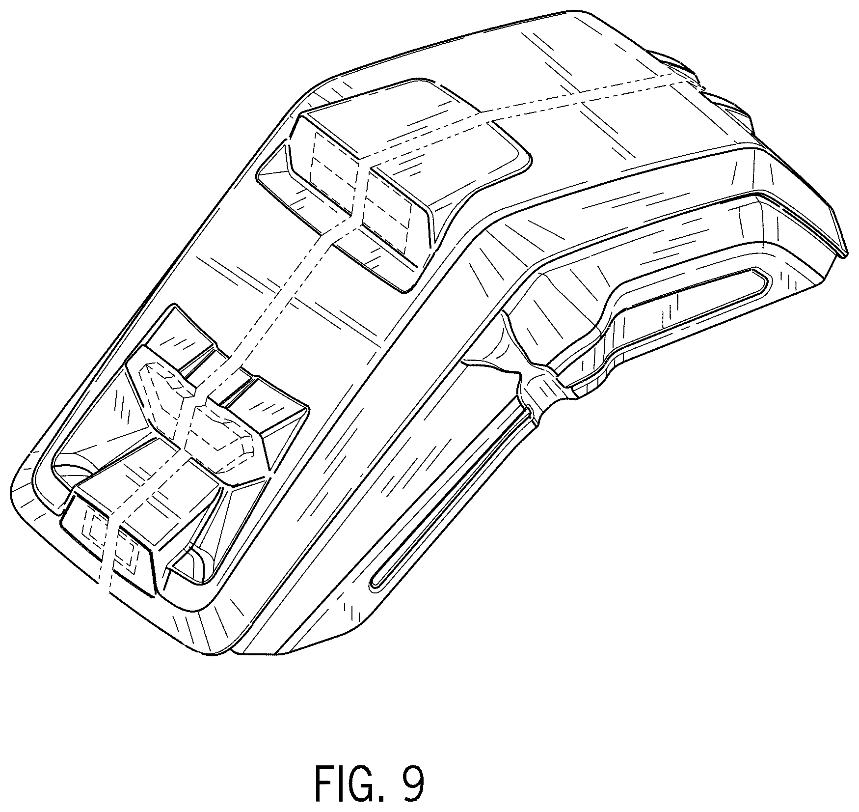
FIG. 9 is an enlarged rear perspective view thereof shown with a symbolic break in width;
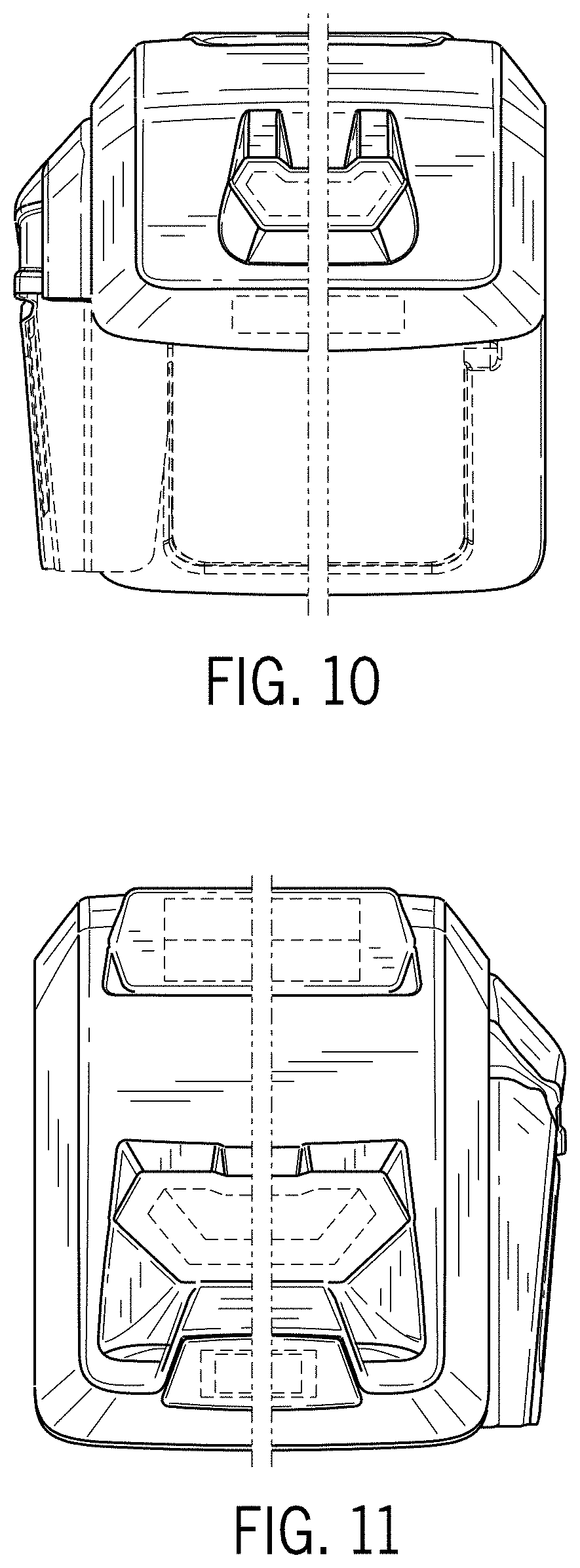
FIG. 10 is a front elevation view thereof;
FIG. 11 is a rear elevation view thereof;
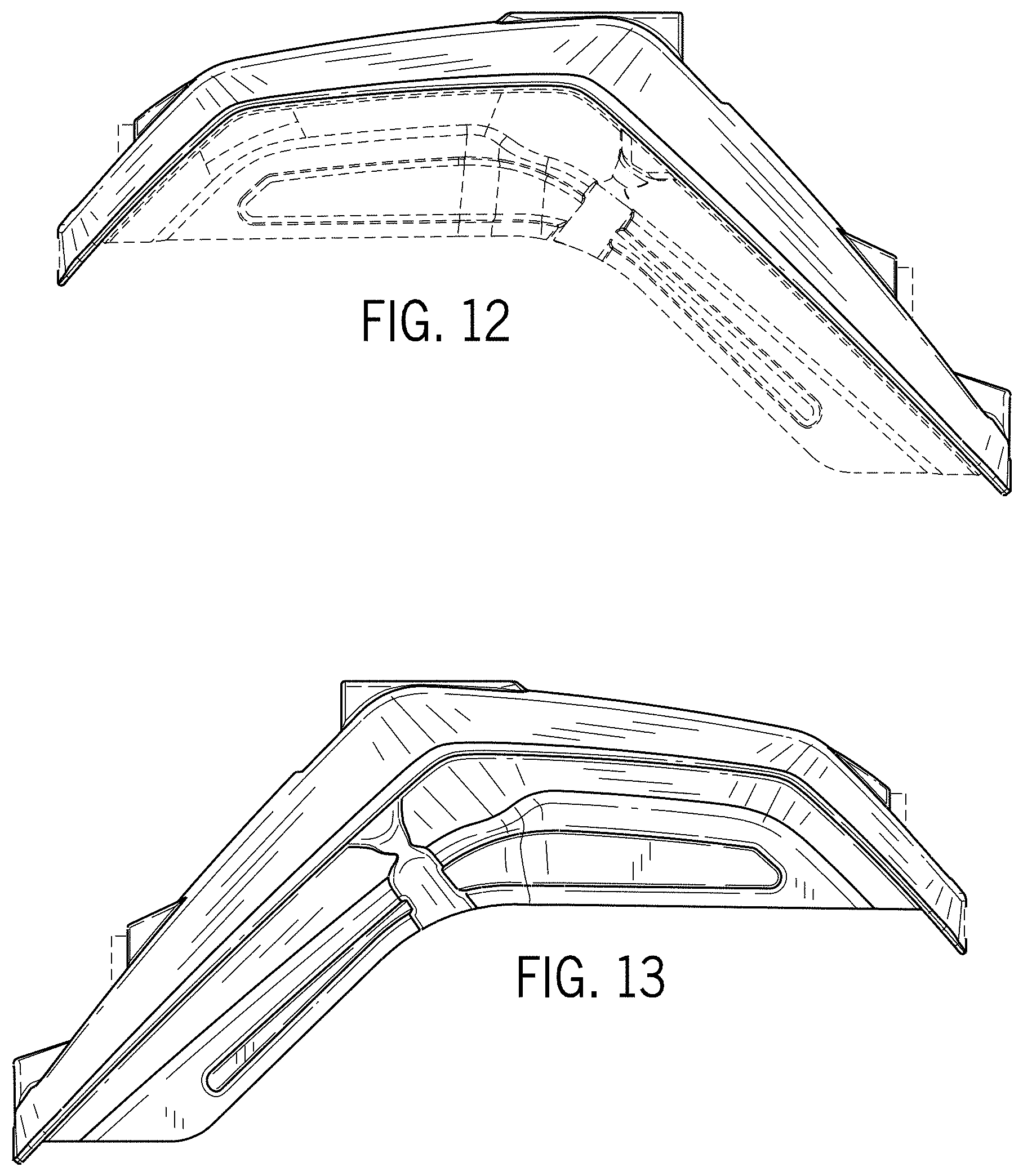
FIG. 12 is a first side elevation view thereof;
FIG. 13 is a second side elevation view thereof;
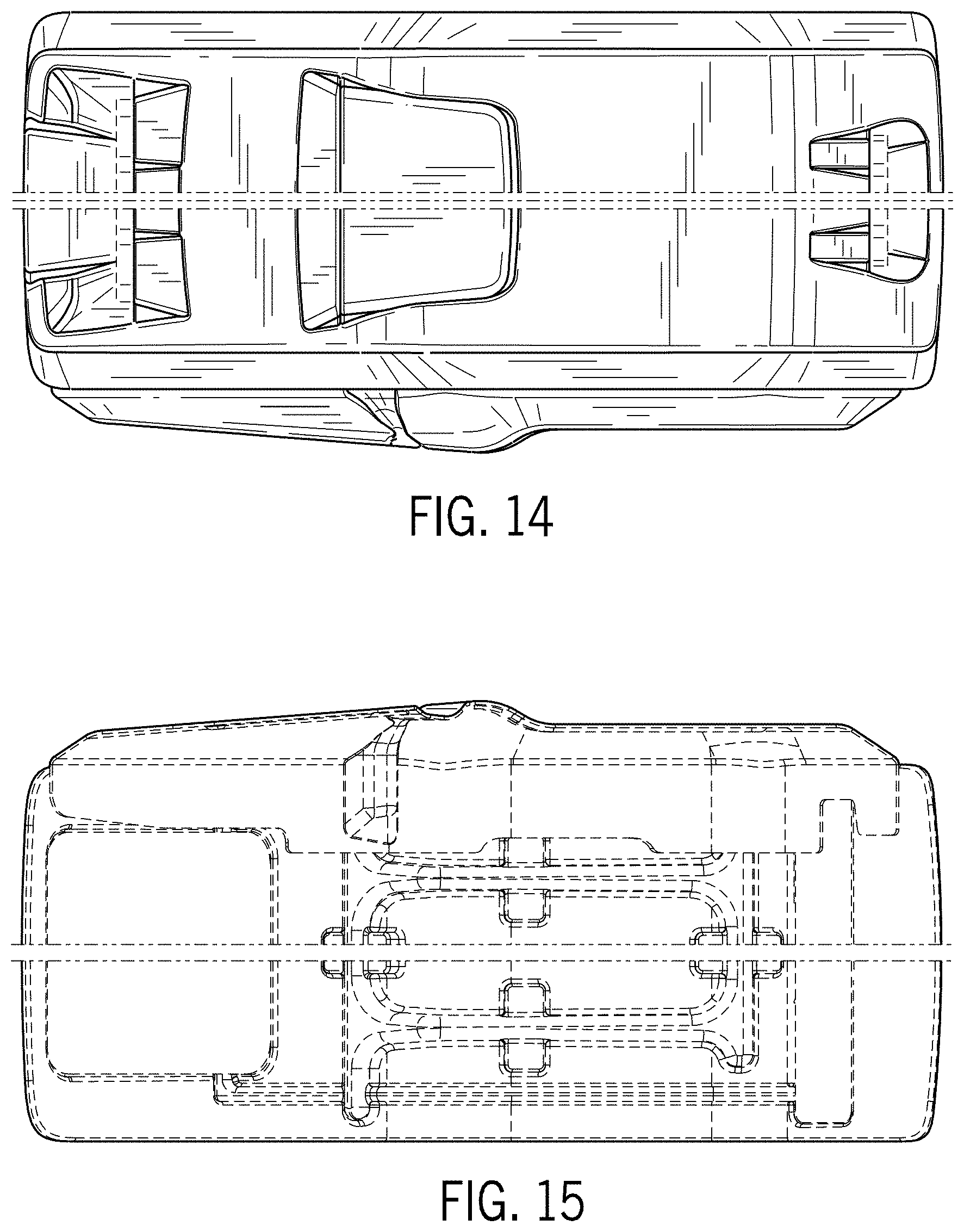
FIG. 14 is a top plan view thereof;
FIG. 15 is a bottom plan view thereof;
FIG. 16 is a rear perspective view of a fender for work vehicle according to according to another embodiment of our new design;
FIG. 17 is an enlarged rear perspective view thereof;
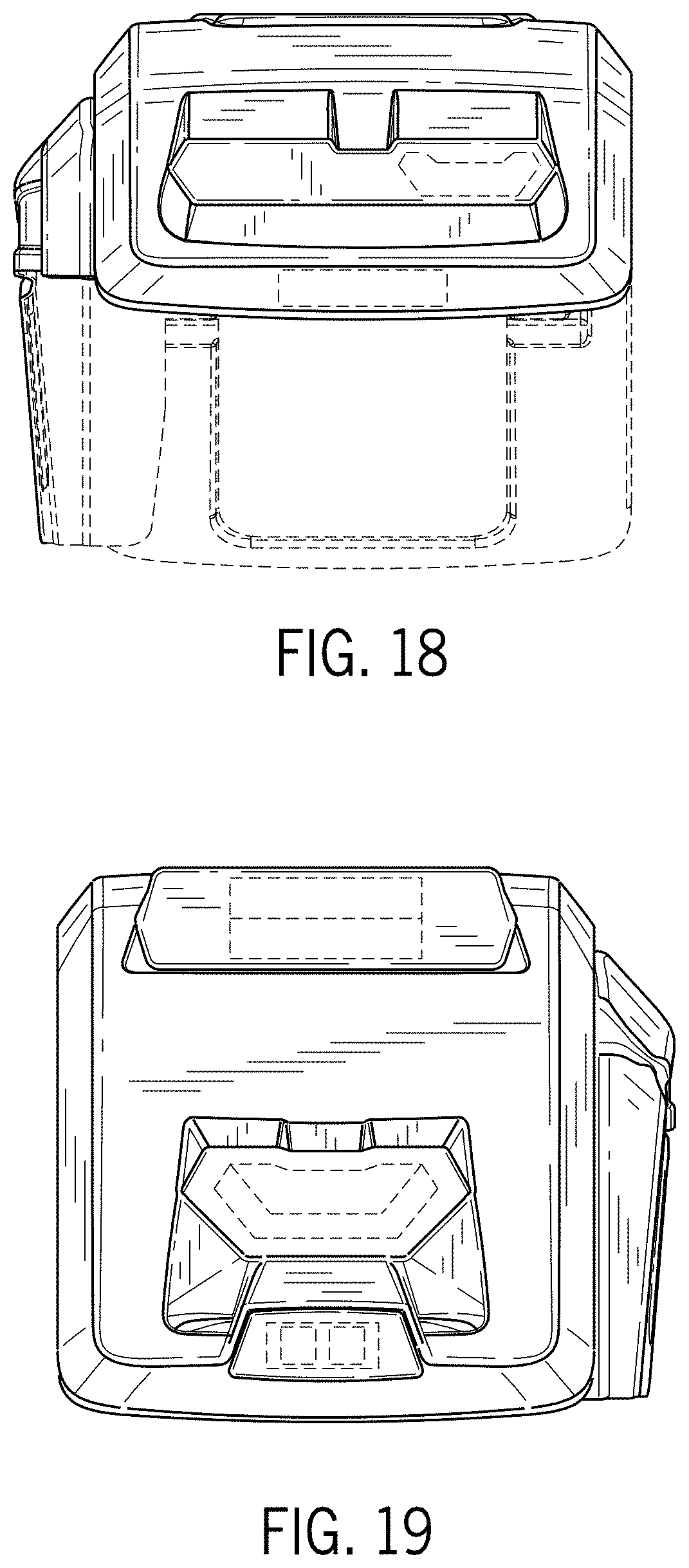
FIG. 18 is a front elevation view thereof;
FIG. 19 is a rear elevation view thereof;
FIG. 20 is a first side elevation view thereof;
FIG. 21 is a second side elevation view thereof;
FIG. 22 is a top plan view thereof;
FIG. 23 is a bottom plan view thereof;
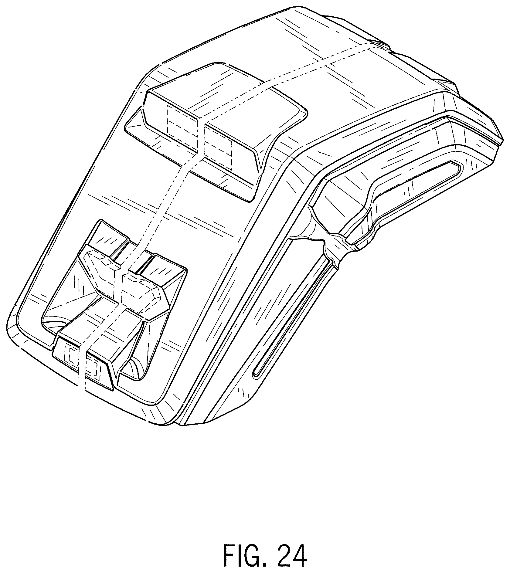
FIG. 24 is an enlarged rear perspective view thereof shown with a symbolic break in width;
FIG. 25 is a front elevation view thereof;
FIG. 26 is a rear elevation view thereof;
FIG. 27 is a first side elevation view thereof;
FIG. 28 is a second side elevation view thereof;
FIG. 29 is a top plan view thereof; and,
FIG. 30 is a bottom plan view thereof.
FIGS. 1-30 illustrate the fender for work vehicle for on a left side of an example work vehicle when viewed from the perspective of FIGS. 1 and 16. The fender for work vehicle may be on the right side of a work vehicle and will be understood to be viewed as mirror images of the views shown in FIGS. 2-15 and 17-30.
The evenly dashed lines in the figures depict environmental features and portions of the article that form no part of the claimed design. The unevenly dashed lines represent a symbolic break across the width of the article and the appearance of any portion of the article between these break lines forms no part of the claimed design.
* * * * *
D00000
D00001
D00002
D00003
D00004
D00005
D00006
D00007
D00008
D00009
D00010
D00011
D00012
D00013

D00014

D00015
D00016

D00017

D00018

XML
uspto.report is an independent third-party trademark research tool that is not affiliated, endorsed, or sponsored by the United States Patent and Trademark Office (USPTO) or any other governmental organization. The information provided by uspto.report is based on publicly available data at the time of writing and is intended for informational purposes only.
While we strive to provide accurate and up-to-date information, we do not guarantee the accuracy, completeness, reliability, or suitability of the information displayed on this site. The use of this site is at your own risk. Any reliance you place on such information is therefore strictly at your own risk.
All official trademark data, including owner information, should be verified by visiting the official USPTO website at www.uspto.gov. This site is not intended to replace professional legal advice and should not be used as a substitute for consulting with a legal professional who is knowledgeable about trademark law.