Heat sink clip and attachment
Azar , et al. Feb
U.S. patent number D876,372 [Application Number D/654,812] was granted by the patent office on 2020-02-25 for heat sink clip and attachment. This patent grant is currently assigned to Advanced Thermal Solutions, Inc.. The grantee listed for this patent is Advanced Thermal Solutions, Inc.. Invention is credited to Kaveh Azar, Vineet Sunil Barot, Anatoly Pikovsky.


View All Diagrams
| United States Patent | D876,372 |
| Azar , et al. | February 25, 2020 |
Heat sink clip and attachment
Claims
CLAIM The ornamental design for a heat sink clip and attachment, as shown and described.
| Inventors: | Azar; Kaveh (Quincy, MA), Barot; Vineet Sunil (Allston, MA), Pikovsky; Anatoly (Sharon, MA) | ||||||||||
|---|---|---|---|---|---|---|---|---|---|---|---|
| Applicant: |
|
||||||||||
| Assignee: | Advanced Thermal Solutions,
Inc. (Norwood, MA) |
||||||||||
| Appl. No.: | D/654,812 | ||||||||||
| Filed: | June 27, 2018 |
| Current U.S. Class: | D13/179 |
| Current International Class: | 1303 |
| Field of Search: | ;D13/179,182 ;D15/199 ;D26/138,141,152,142 |
References Cited [Referenced By]
U.S. Patent Documents
| 5329426 | July 1994 | Villani |
| D376349 | December 1996 | Campanella et al. |
| 5581442 | December 1996 | Morosas |
| 5699229 | December 1997 | Brownell |
| 5804875 | September 1998 | Remsburg et al. |
| 5881800 | March 1999 | Chung |
| 6153932 | November 2000 | Liang |
| 6188131 | February 2001 | Nereng |
| 6239974 | May 2001 | Tseng |
| 6392885 | May 2002 | Lee et al. |
| 6396695 | May 2002 | Lee et al. |
| D496006 | September 2004 | Tsai et al. |
| 6856511 | February 2005 | Viernes et al. |
| 6952348 | October 2005 | Wu |
| 6962192 | November 2005 | Lee |
| 6992889 | January 2006 | Kashiwagi et al. |
| D514529 | February 2006 | Yu |
| 7009843 | March 2006 | Lee et al. |
| D555109 | November 2007 | Lee et al. |
| 7307842 | December 2007 | Liang |
| 7498673 | March 2009 | Awad et al. |
| 7518875 | April 2009 | Desrosiers et al. |
| 7564687 | July 2009 | Liu |
| 7606032 | October 2009 | Lin |
| 7619892 | November 2009 | Liang |
| D609198 | February 2010 | Hsu |
| 7736153 | June 2010 | Cheng |
| D622227 | August 2010 | Huang et al. |
| 7768786 | August 2010 | Liang |
| 7785126 | August 2010 | Peng et al. |
| 7834444 | November 2010 | Awad et al. |
| D638807 | May 2011 | Chan et al. |
| 7961473 | June 2011 | Bohannon et al. |
| 8248786 | August 2012 | Cheng |
| 8274793 | September 2012 | Wang et al. |
| 8300413 | October 2012 | Chen |
| 8780563 | July 2014 | Lostoski |
| 9118141 | August 2015 | Yeh |
| 9603286 | March 2017 | Carpenter et al. |
| D804434 | December 2017 | Lu et al. |
| 9875951 | January 2018 | Glover et al. |
| D835590 | December 2018 | Azar |
| D837753 | January 2019 | Azar |
| 2007/0086170 | April 2007 | Liang |
| 2008/0128110 | June 2008 | Lai |
| 2008/0144289 | June 2008 | Desrosiers |
| 2008/0174968 | July 2008 | Feng |
| 2008/0197483 | August 2008 | Ouyang |
| 2009/0021917 | January 2009 | Floyd |
| 2009/0027858 | January 2009 | Lai |
| 2009/0203245 | August 2009 | Chiang |
| 2010/0029120 | February 2010 | Peng |
| 2010/0120268 | May 2010 | Yeh |
| 2010/0172105 | July 2010 | Liang |
| 2010/0200206 | August 2010 | Mandrone |
| 2011/0304979 | December 2011 | Peterson |
| 2013/0146252 | June 2013 | Yang |
| 2017/0006696 | January 2017 | Ma |
Other References
|
Digi-Key, "Advanced Thermal Solutions Inc. ATS-MG170-R0", (https://www.digikey.com/product-detail/en/ATS-MG170-R0/ATS1912-ND/501782- 0). cited by applicant . Digi-Key, "Advanced Thermal Solutions Inc. ATS-X50150B-C1-R0", (https://www.digikey.com/products/en?vendor=Advanced%20Thermal%20Solution- s&keywords=ATS1944-ND). cited by applicant . Radian, "EZ Snap Clip", (https://radianheatsinks.com/ez-snap-clip). cited by applicant. |
Primary Examiner: Rivas; April
Attorney, Agent or Firm: Lieberman & Brandsdorfer, LLC
Description
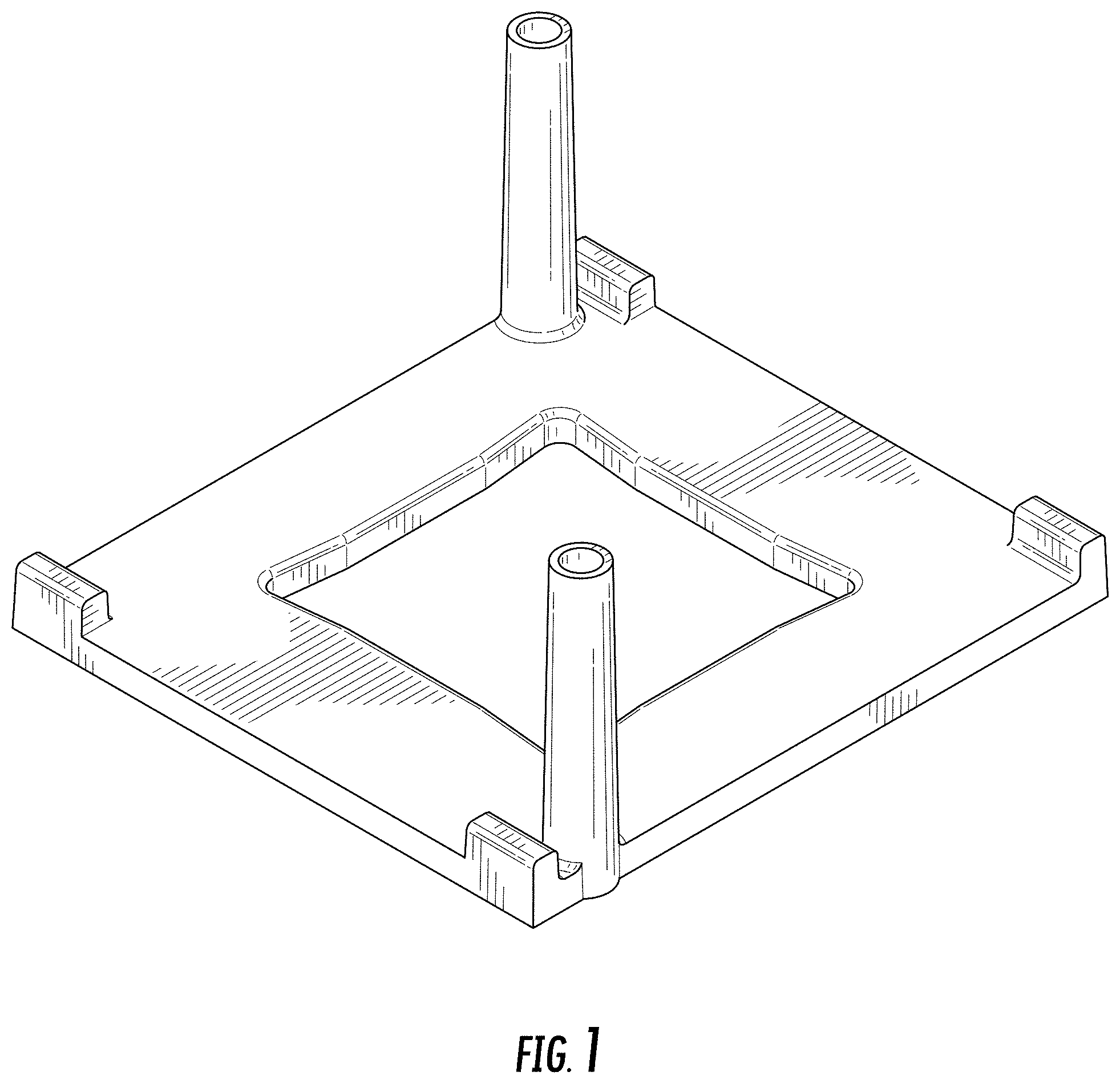
FIG. 1 is a front perspective view of a heat sink clip and attachment showing our new design;
FIG. 2 is a bottom perspective view of the heat sink clip and attachment showing the new design;
FIG. 3 is a front view of the heat sink clip and attachment shown in FIG. 1;
FIG. 4 is a back view of FIG. 1;
FIG. 5 is a left side view of FIG. 1;
FIG. 6 is a right side view of FIG. 1;
FIG. 7 is a top view of FIG. 1;
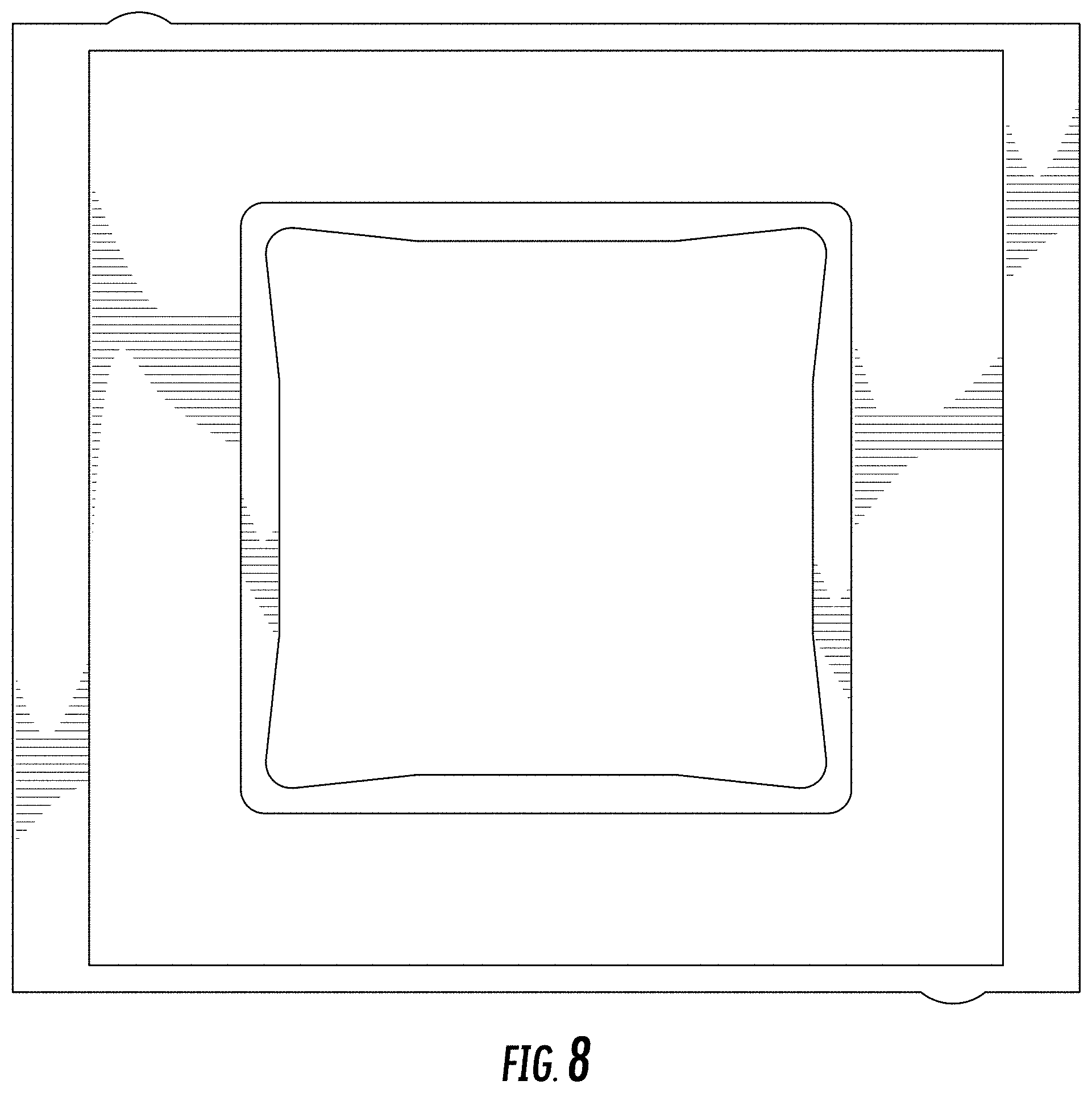
FIG. 8 is a bottom view of FIG. 2;
FIG. 9 is an exploded parts view thereof showing the heat sink clip and attachment, the mounting shown in broken lines;
FIG. 10 is an assembled parts view thereof showing the heat sink clip and attachment, the mounting shown in broken lines.
FIG. 11 is a cross-sectional view along the line 11 of FIG. 7; and,
FIG. 12 is a partial and enlarged cross-sectional view of the detail shown in dash line 12 observed in dot-dash line(s) 12 of FIG. 11.
The broken lines illustrate the environmental mounting and form no part of the claimed design.
* * * * *
References
D00000
D00001
D00002
D00003
D00004
D00005
D00006
D00007
D00008
D00009
D00010
D00011
XML
uspto.report is an independent third-party trademark research tool that is not affiliated, endorsed, or sponsored by the United States Patent and Trademark Office (USPTO) or any other governmental organization. The information provided by uspto.report is based on publicly available data at the time of writing and is intended for informational purposes only.
While we strive to provide accurate and up-to-date information, we do not guarantee the accuracy, completeness, reliability, or suitability of the information displayed on this site. The use of this site is at your own risk. Any reliance you place on such information is therefore strictly at your own risk.
All official trademark data, including owner information, should be verified by visiting the official USPTO website at www.uspto.gov. This site is not intended to replace professional legal advice and should not be used as a substitute for consulting with a legal professional who is knowledgeable about trademark law.