System and method for displaying anatomy and devices on a movable display
Wallace , et al. June 1, 2
U.S. patent number 11,020,016 [Application Number 14/286,793] was granted by the patent office on 2021-06-01 for system and method for displaying anatomy and devices on a movable display. This patent grant is currently assigned to Auris Health, Inc.. The grantee listed for this patent is Auris Surgical Robotics, Inc.. Invention is credited to Aaron Grogan, Gregory Stahler, Daniel Wallace.


| United States Patent | 11,020,016 |
| Wallace , et al. | June 1, 2021 |
System and method for displaying anatomy and devices on a movable display
Abstract
An image display system is provided comprised of a virtual window system that creates a visual coherency between the patient's anatomical images and the actual patient by aligning the image on the display to the patient and then presenting the image to the user in a way that feels as if the user is looking directly into the patient through the display. The image shown within the image display system is dependent upon the position of the image display apparatus and the position of the user so that the display orientation of the image may be biased slightly toward the user to improve ergonomics and usability.
| Inventors: | Wallace; Daniel (Santa Cruz, CA), Stahler; Gregory (San Jose, CA), Grogan; Aaron (Scotts Valley, CA) | ||||||||||
|---|---|---|---|---|---|---|---|---|---|---|---|
| Applicant: |
|
||||||||||
| Assignee: | Auris Health, Inc. (Redwood
City, CA) |
||||||||||
| Family ID: | 51985884 | ||||||||||
| Appl. No.: | 14/286,793 | ||||||||||
| Filed: | May 23, 2014 |
Prior Publication Data
| Document Identifier | Publication Date | |
|---|---|---|
| US 20140357984 A1 | Dec 4, 2014 | |
Related U.S. Patent Documents
| Application Number | Filing Date | Patent Number | Issue Date | ||
|---|---|---|---|---|---|
| 61829078 | May 30, 2013 | ||||
| Current U.S. Class: | 1/1 |
| Current CPC Class: | A61B 5/7425 (20130101); A61B 5/062 (20130101); A61B 90/37 (20160201); A61B 8/0833 (20130101); A61B 5/7445 (20130101); A61B 2034/2051 (20160201); A61B 6/487 (20130101); A61B 5/055 (20130101) |
| Current International Class: | A61B 34/10 (20160101); A61B 34/20 (20160101); A61B 34/30 (20160101); A61B 90/00 (20160101); A61B 5/00 (20060101); A61B 5/06 (20060101); A61B 6/00 (20060101); A61B 8/08 (20060101); A61B 5/055 (20060101) |
| Field of Search: | ;600/415,420,424,425,426,429,431,443 |
References Cited [Referenced By]
U.S. Patent Documents
| 4745908 | May 1988 | Wardle |
| 4771262 | September 1988 | Reuss |
| 4896554 | January 1990 | Culver |
| 5008528 | April 1991 | Duchon |
| 5134390 | July 1992 | Kishimoto et al. |
| 5176310 | January 1993 | Akiyama et al. |
| 5273025 | December 1993 | Sakiyam et al. |
| 5280781 | January 1994 | Oku |
| 5499632 | March 1996 | Hill et al. |
| 5524180 | June 1996 | Wang et al. |
| 5526812 | June 1996 | Dumoulin et al. |
| 5550953 | August 1996 | Seraji |
| 5694142 | December 1997 | Dumoulin et al. |
| 5762458 | June 1998 | Wang et al. |
| 5808665 | September 1998 | Green |
| 5831614 | November 1998 | Tognazzini et al. |
| 5899851 | May 1999 | Koninckx |
| 5935075 | August 1999 | Casscells |
| 5963770 | October 1999 | Eakin |
| 6007550 | December 1999 | Wang et al. |
| 6016439 | January 2000 | Acker |
| 6038467 | March 2000 | De Bliek et al. |
| 6047080 | April 2000 | Chen |
| 6059718 | May 2000 | Taniguchi et al. |
| 6063095 | May 2000 | Wang et al. |
| 6096004 | August 2000 | Meglan et al. |
| 6167292 | December 2000 | Badano |
| 6203493 | March 2001 | Ben-Haim |
| 6246784 | June 2001 | Summers |
| 6246898 | June 2001 | Vesely |
| 6332089 | December 2001 | Acker |
| 6425865 | July 2002 | Salcudean |
| 6466198 | October 2002 | Feinstein |
| 6468265 | October 2002 | Evans et al. |
| 6490467 | December 2002 | Bucholz |
| 6516421 | February 2003 | Peters |
| 6553251 | April 2003 | Lahdesmaki |
| 6665554 | December 2003 | Charles |
| 6690963 | February 2004 | Ben-Haim |
| 6690964 | February 2004 | Bieger et al. |
| 6755797 | June 2004 | Stouffer |
| 6812842 | November 2004 | Dimmer |
| 6856827 | February 2005 | Seeley et al. |
| 6899672 | May 2005 | Chin |
| 6926709 | August 2005 | Beiger et al. |
| 7180976 | February 2007 | Wink |
| 7203277 | April 2007 | Birkenbach et al. |
| 7206627 | April 2007 | Abovitz |
| 7233820 | June 2007 | Gilboa |
| 7386339 | June 2008 | Strommer et al. |
| 7594925 | September 2009 | Danek |
| 7618371 | November 2009 | Younge et al. |
| 7756563 | July 2010 | Higgins |
| 7774044 | August 2010 | Sauer et al. |
| 7850642 | December 2010 | Moll et al. |
| 7880739 | February 2011 | Long et al. |
| 7901348 | March 2011 | Soper |
| 7935059 | May 2011 | Younge et al. |
| 7963288 | June 2011 | Rosenberg et al. |
| 7972298 | July 2011 | Wallace et al. |
| 7974681 | July 2011 | Wallace et al. |
| 7976539 | July 2011 | Hlavka et al. |
| 8005537 | August 2011 | Hlavka et al. |
| 8021326 | September 2011 | Moll et al. |
| 8041413 | October 2011 | Barbagli et al. |
| 8050523 | November 2011 | Younge et al. |
| 8052621 | November 2011 | Wallace et al. |
| 8052636 | November 2011 | Moll et al. |
| 8092397 | January 2012 | Wallace et al. |
| 8108069 | January 2012 | Stahler et al. |
| 8155403 | April 2012 | Tschirren |
| 8172747 | May 2012 | Wallace et al. |
| 8180114 | May 2012 | Nishihara et al. |
| 8190238 | May 2012 | Moll et al. |
| 8257303 | September 2012 | Moll et al. |
| 8285364 | October 2012 | Barbagli et al. |
| 8290571 | October 2012 | Younge et al. |
| 8298135 | October 2012 | Ito et al. |
| 8311626 | November 2012 | Hlavka et al. |
| 8317746 | November 2012 | Sewell et al. |
| 8388538 | March 2013 | Younge et al. |
| 8388556 | March 2013 | Wallace et al. |
| 8394054 | March 2013 | Wallace et al. |
| 8409136 | April 2013 | Wallace et al. |
| 8409172 | April 2013 | Moll et al. |
| 8409234 | April 2013 | Stahler et al. |
| 8460236 | June 2013 | Roelle et al. |
| 8498691 | July 2013 | Moll et al. |
| 8617102 | December 2013 | Moll et al. |
| 8716973 | May 2014 | Lammertse |
| 8718837 | May 2014 | Wang et al. |
| 8720448 | May 2014 | Reis et al. |
| 8801661 | August 2014 | Moll et al. |
| 8821376 | September 2014 | Tolkowsky |
| 8858424 | October 2014 | Hasegawa |
| 8926603 | January 2015 | Hlavka et al. |
| 8929631 | January 2015 | Pfister et al. |
| 8961533 | February 2015 | Stahler et al. |
| 8971597 | March 2015 | Zhao et al. |
| 8974408 | March 2015 | Wallace et al. |
| 9014851 | April 2015 | Wong et al. |
| 9084623 | July 2015 | Gomez et al. |
| 9125639 | September 2015 | Mathis |
| 9138129 | September 2015 | Diolaiti |
| 9173713 | November 2015 | Hart et al. |
| 9183354 | November 2015 | Baker et al. |
| 9186046 | November 2015 | Ramamurthy et al. |
| 9241767 | January 2016 | Prisco et al. |
| 9272416 | March 2016 | Hourtash et al. |
| 9283046 | March 2016 | Walker et al. |
| 9289578 | March 2016 | Walker et al. |
| 9358076 | June 2016 | Moll et al. |
| 9457168 | October 2016 | Moll et al. |
| 9459087 | October 2016 | Dunbar |
| 9498291 | November 2016 | Balaji et al. |
| 9498601 | November 2016 | Tanner et al. |
| 9503681 | November 2016 | Popescu et al. |
| 9504604 | November 2016 | Alvarez |
| 9561019 | February 2017 | Mihailescu et al. |
| 9561083 | February 2017 | Yu et al. |
| 9566414 | February 2017 | Wong et al. |
| 9603668 | March 2017 | Weingarten et al. |
| 9622827 | April 2017 | Yu et al. |
| 9629682 | April 2017 | Wallace et al. |
| 9636184 | May 2017 | Lee et al. |
| 9710921 | July 2017 | Wong et al. |
| 9713509 | July 2017 | Schuh et al. |
| 9717563 | August 2017 | Tognaccini |
| 9727963 | August 2017 | Mintz et al. |
| 9737371 | August 2017 | Romo et al. |
| 9737373 | August 2017 | Schuh |
| 9744335 | August 2017 | Jiang |
| 9763741 | September 2017 | Alvarez et al. |
| 9770216 | September 2017 | Brown et al. |
| 9788910 | October 2017 | Schuh |
| 9827061 | November 2017 | Balaji et al. |
| 9844412 | December 2017 | Bogusky et al. |
| 9867635 | January 2018 | Alvarez et al. |
| 9918681 | March 2018 | Wallace et al. |
| 10016900 | July 2018 | Meyer et al. |
| 10022192 | July 2018 | Ummalaneni |
| 10028789 | July 2018 | Quaid et al. |
| 10046140 | August 2018 | Kokish et al. |
| 10123843 | November 2018 | Wong et al. |
| 10130427 | November 2018 | Tanner et al. |
| 10136950 | November 2018 | Schoenefeld |
| 10143526 | December 2018 | Walker et al. |
| 10145747 | December 2018 | Lin et al. |
| 10159532 | December 2018 | Ummalaneni et al. |
| 10206746 | February 2019 | Walker et al. |
| 10278778 | May 2019 | State |
| 10285574 | May 2019 | Landey et al. |
| 10299870 | May 2019 | Connolly et al. |
| 10346976 | July 2019 | Averbuch et al. |
| 10482599 | November 2019 | Mintz et al. |
| 10820954 | November 2020 | Marsot et al. |
| 2001/0021843 | September 2001 | Bosselmann et al. |
| 2001/0039421 | November 2001 | Heilbrun |
| 2002/0065455 | May 2002 | Ben-Haim et al. |
| 2002/0077533 | June 2002 | Bieger et al. |
| 2002/0082612 | June 2002 | Moll et al. |
| 2002/0120188 | August 2002 | Brock et al. |
| 2002/0161280 | October 2002 | Chatenever et al. |
| 2002/0173878 | November 2002 | Watanabe |
| 2003/0105603 | June 2003 | Hardesty |
| 2003/0125622 | July 2003 | Schweikard |
| 2003/0181809 | September 2003 | Hall et al. |
| 2003/0195664 | October 2003 | Nowlin et al. |
| 2004/0047044 | March 2004 | Dalton |
| 2004/0072066 | April 2004 | Cho et al. |
| 2004/0186349 | September 2004 | Ewers |
| 2004/0249267 | December 2004 | Gilboa |
| 2004/0263535 | December 2004 | Birkenbach |
| 2005/0027397 | February 2005 | Niemeyer |
| 2005/0043718 | February 2005 | Madhani |
| 2005/0060006 | March 2005 | Pflueger |
| 2005/0085714 | April 2005 | Foley |
| 2005/0107679 | May 2005 | Geiger |
| 2005/0143649 | June 2005 | Minai et al. |
| 2005/0143655 | June 2005 | Satoh |
| 2005/0182295 | August 2005 | Soper et al. |
| 2005/0182319 | August 2005 | Glossop |
| 2005/0193451 | September 2005 | Quistgaard |
| 2005/0197557 | September 2005 | Strommer et al. |
| 2005/0222554 | October 2005 | Wallace et al. |
| 2005/0256398 | November 2005 | Hastings |
| 2005/0272975 | December 2005 | McWeeney et al. |
| 2006/0004286 | January 2006 | Chang |
| 2006/0015096 | January 2006 | Hauck et al. |
| 2006/0025668 | February 2006 | Peterson |
| 2006/0058643 | March 2006 | Florent |
| 2006/0079745 | April 2006 | Viswanathan et al. |
| 2006/0084860 | April 2006 | Geiger |
| 2006/0095022 | May 2006 | Moll et al. |
| 2006/0095066 | May 2006 | Chang |
| 2006/0098851 | May 2006 | Shoham |
| 2006/0149134 | July 2006 | Soper et al. |
| 2006/0173290 | August 2006 | Lavallee et al. |
| 2006/0184016 | August 2006 | Glossop |
| 2006/0200026 | September 2006 | Wallace et al. |
| 2006/0209019 | September 2006 | Hu |
| 2006/0258935 | November 2006 | Pile-Spellman et al. |
| 2006/0258938 | November 2006 | Hoffman et al. |
| 2007/0032826 | February 2007 | Schwartz |
| 2007/0055128 | March 2007 | Glossop |
| 2007/0055144 | March 2007 | Neustadter |
| 2007/0073136 | March 2007 | Metzger |
| 2007/0083098 | April 2007 | Stern et al. |
| 2007/0083193 | April 2007 | Werneth |
| 2007/0123748 | May 2007 | Meglan |
| 2007/0135886 | June 2007 | Maschke |
| 2007/0138992 | June 2007 | Prisco et al. |
| 2007/0144298 | June 2007 | Miller |
| 2007/0156019 | July 2007 | Larkin et al. |
| 2007/0161857 | July 2007 | Durant et al. |
| 2007/0167743 | July 2007 | Honda |
| 2007/0167801 | July 2007 | Webler et al. |
| 2007/0185486 | August 2007 | Hauck et al. |
| 2007/0208252 | September 2007 | Makower |
| 2007/0253599 | November 2007 | White et al. |
| 2007/0269001 | November 2007 | Maschke |
| 2007/0293721 | December 2007 | Gilboa |
| 2007/0299353 | December 2007 | Harlev et al. |
| 2008/0027313 | January 2008 | Shachar |
| 2008/0027464 | January 2008 | Moll et al. |
| 2008/0033442 | February 2008 | Amoit |
| 2008/0071140 | March 2008 | Gattani |
| 2008/0079421 | April 2008 | Jensen |
| 2008/0082109 | April 2008 | Moll et al. |
| 2008/0097465 | April 2008 | Rollins et al. |
| 2008/0103389 | May 2008 | Begelman et al. |
| 2008/0108870 | May 2008 | Wiita et al. |
| 2008/0118118 | May 2008 | Berger |
| 2008/0118135 | May 2008 | Averbach |
| 2008/0123921 | May 2008 | Gielen et al. |
| 2008/0140087 | June 2008 | Barbagli |
| 2008/0147089 | June 2008 | Loh |
| 2008/0159653 | July 2008 | Dunki-Jacobs et al. |
| 2008/0161681 | July 2008 | Hauck |
| 2008/0183064 | July 2008 | Chandonnet |
| 2008/0183068 | July 2008 | Carls |
| 2008/0183073 | July 2008 | Higgins et al. |
| 2008/0183188 | July 2008 | Carls et al. |
| 2008/0201016 | August 2008 | Finlay |
| 2008/0207997 | August 2008 | Higgins et al. |
| 2008/0212082 | September 2008 | Froggatt et al. |
| 2008/0218770 | September 2008 | Moll et al. |
| 2008/0243064 | October 2008 | Stahler et al. |
| 2008/0243142 | October 2008 | Gildenberg |
| 2008/0249536 | October 2008 | Stahler et al. |
| 2008/0262297 | October 2008 | Gilboa |
| 2008/0262480 | October 2008 | Stahler et al. |
| 2008/0262513 | October 2008 | Stahler et al. |
| 2008/0275349 | November 2008 | Halperin |
| 2008/0287963 | November 2008 | Rogers et al. |
| 2008/0306490 | December 2008 | Lakin et al. |
| 2008/0312501 | December 2008 | Hasegawa et al. |
| 2009/0024141 | January 2009 | Stahler et al. |
| 2009/0030307 | January 2009 | Govari |
| 2009/0054729 | February 2009 | Mori |
| 2009/0062602 | March 2009 | Rosenberg et al. |
| 2009/0076476 | March 2009 | Barbagli et al. |
| 2009/0138025 | May 2009 | Stahler et al. |
| 2009/0149867 | June 2009 | Glozman |
| 2009/0209817 | August 2009 | Averbuch |
| 2009/0227861 | September 2009 | Ganatra |
| 2009/0228020 | September 2009 | Wallace et al. |
| 2009/0248036 | October 2009 | Hoffman et al. |
| 2009/0254083 | October 2009 | Wallace et al. |
| 2009/0259230 | October 2009 | Khadem |
| 2009/0259412 | October 2009 | Brogardh |
| 2009/0262109 | October 2009 | Markowitz et al. |
| 2009/0292166 | November 2009 | Ito |
| 2009/0295797 | December 2009 | Sakaguchi |
| 2009/0322671 | December 2009 | Scott et al. |
| 2009/0326322 | December 2009 | Diolaiti |
| 2009/0326556 | December 2009 | Diolaiti et al. |
| 2010/0008555 | January 2010 | Trumer |
| 2010/0019890 | January 2010 | Helmer et al. |
| 2010/0030061 | February 2010 | Canfield |
| 2010/0039506 | February 2010 | Sarvestani et al. |
| 2010/0041949 | February 2010 | Tolkowsky |
| 2010/0053151 | March 2010 | Marti et al. |
| 2010/0054536 | March 2010 | Huang |
| 2010/0076263 | March 2010 | Tanaka |
| 2010/0113852 | May 2010 | Sydora |
| 2010/0121139 | May 2010 | OuYang |
| 2010/0121269 | May 2010 | Goldenberg |
| 2010/0125284 | May 2010 | Tanner et al. |
| 2010/0160733 | June 2010 | Gilboa |
| 2010/0161022 | June 2010 | Tolkowsky |
| 2010/0161129 | June 2010 | Costa et al. |
| 2010/0204613 | August 2010 | Rollins et al. |
| 2010/0225209 | September 2010 | Goldberg |
| 2010/0240989 | September 2010 | Stoianovici |
| 2010/0290530 | November 2010 | Huang et al. |
| 2010/0292565 | November 2010 | Meyer |
| 2010/0295931 | November 2010 | Schmidt |
| 2010/0298641 | November 2010 | Tanaka |
| 2010/0328455 | December 2010 | Nam et al. |
| 2011/0015648 | January 2011 | Alvarez et al. |
| 2011/0021926 | January 2011 | Spencer |
| 2011/0054303 | March 2011 | Barrick |
| 2011/0092808 | April 2011 | Shachar |
| 2011/0113852 | May 2011 | Prisco |
| 2011/0118748 | May 2011 | Itkowitz |
| 2011/0118752 | May 2011 | Itkowitz et al. |
| 2011/0118753 | May 2011 | Itkowitz et al. |
| 2011/0130718 | June 2011 | Kidd et al. |
| 2011/0184238 | July 2011 | Higgins |
| 2011/0196199 | August 2011 | Donhowe et al. |
| 2011/0234780 | September 2011 | Ito |
| 2011/0235855 | September 2011 | Smith |
| 2011/0238010 | September 2011 | Kirschenman et al. |
| 2011/0238082 | September 2011 | Wenderow |
| 2011/0238083 | September 2011 | Moll et al. |
| 2011/0245665 | October 2011 | Nentwick |
| 2011/0248987 | October 2011 | Mitchell |
| 2011/0249016 | October 2011 | Zhang |
| 2011/0257480 | October 2011 | Takahashi |
| 2011/0270273 | November 2011 | Moll et al. |
| 2011/0276058 | November 2011 | Choi et al. |
| 2011/0276179 | November 2011 | Banks et al. |
| 2011/0295247 | December 2011 | Schlesinger et al. |
| 2011/0295248 | December 2011 | Wallace et al. |
| 2011/0295267 | December 2011 | Tanner et al. |
| 2011/0295268 | December 2011 | Roelle et al. |
| 2011/0306873 | December 2011 | Shenai et al. |
| 2011/0319910 | December 2011 | Roelle et al. |
| 2012/0046521 | February 2012 | Hunter et al. |
| 2012/0056986 | March 2012 | Popovic |
| 2012/0059392 | March 2012 | Diolaiti |
| 2012/0062714 | March 2012 | Liu |
| 2012/0065481 | March 2012 | Hunter |
| 2012/0069167 | March 2012 | Liu et al. |
| 2012/0071752 | March 2012 | Sewell |
| 2012/0071782 | March 2012 | Patil et al. |
| 2012/0071891 | March 2012 | Itkowitz et al. |
| 2012/0071892 | March 2012 | Itkowitz et al. |
| 2012/0071894 | March 2012 | Tanner et al. |
| 2012/0075638 | March 2012 | Rollins et al. |
| 2012/0078053 | March 2012 | Phee et al. |
| 2012/0082351 | April 2012 | Higgins |
| 2012/0103123 | May 2012 | McInroy et al. |
| 2012/0116253 | May 2012 | Wallace et al. |
| 2012/0120305 | May 2012 | Takahashi |
| 2012/0158011 | June 2012 | Sandhu |
| 2012/0165656 | June 2012 | Montag |
| 2012/0191079 | July 2012 | Moll et al. |
| 2012/0203067 | August 2012 | Higgins et al. |
| 2012/0209069 | August 2012 | Popovic |
| 2012/0215094 | August 2012 | Rahimian et al. |
| 2012/0219185 | August 2012 | Hu |
| 2012/0253276 | October 2012 | Govari et al. |
| 2012/0289777 | November 2012 | Chopra |
| 2012/0289783 | November 2012 | Duindam et al. |
| 2012/0296161 | November 2012 | Wallace et al. |
| 2012/0302869 | November 2012 | Koyrakh |
| 2012/0314022 | December 2012 | Jo |
| 2013/0018306 | January 2013 | Ludwin |
| 2013/0060146 | March 2013 | Yang |
| 2013/0072787 | March 2013 | Wallace et al. |
| 2013/0144116 | June 2013 | Cooper et al. |
| 2013/0165854 | June 2013 | Sandhu et al. |
| 2013/0165945 | June 2013 | Roelle |
| 2013/0190741 | July 2013 | Moll et al. |
| 2013/0204124 | August 2013 | Duindam |
| 2013/0225942 | August 2013 | Holsing |
| 2013/0243153 | September 2013 | Sra |
| 2013/0245375 | September 2013 | DiMaio et al. |
| 2013/0246334 | September 2013 | Ahuja |
| 2013/0259315 | October 2013 | Angot et al. |
| 2013/0303892 | November 2013 | Zhao |
| 2013/0317519 | November 2013 | Romo et al. |
| 2013/0345718 | December 2013 | Crawford |
| 2014/0058406 | February 2014 | Tsekos |
| 2014/0072192 | March 2014 | Reiner |
| 2014/0107390 | April 2014 | Brown |
| 2014/0107666 | April 2014 | Madhani |
| 2014/0111457 | April 2014 | Briden et al. |
| 2014/0114180 | April 2014 | Jain |
| 2014/0148808 | April 2014 | Inkpen et al. |
| 2014/0142591 | May 2014 | Alvarez et al. |
| 2014/0180063 | June 2014 | Zhao |
| 2014/0222204 | August 2014 | Kawashima |
| 2014/0235943 | August 2014 | Paris |
| 2014/0243849 | August 2014 | Saglam |
| 2014/0257746 | September 2014 | Dunbar et al. |
| 2014/0264081 | September 2014 | Walker et al. |
| 2014/0275988 | September 2014 | Walker et al. |
| 2014/0276033 | September 2014 | Brannan |
| 2014/0276392 | September 2014 | Wong et al. |
| 2014/0276594 | September 2014 | Tanner et al. |
| 2014/0276933 | September 2014 | Hart et al. |
| 2014/0276937 | September 2014 | Wong et al. |
| 2014/0276938 | September 2014 | Hsu et al. |
| 2014/0277333 | September 2014 | Lewis et al. |
| 2014/0296655 | October 2014 | Akhbardeh et al. |
| 2014/0296657 | October 2014 | Izmirli |
| 2014/0309527 | October 2014 | Namati et al. |
| 2014/0309649 | October 2014 | Alvarez et al. |
| 2014/0343416 | November 2014 | Panescu |
| 2014/0350391 | November 2014 | Prisco et al. |
| 2014/0357953 | December 2014 | Roelle et al. |
| 2014/0357984 | December 2014 | Wallace et al. |
| 2014/0364739 | December 2014 | Liu |
| 2014/0364870 | December 2014 | Alvarez et al. |
| 2014/0379000 | December 2014 | Romo et al. |
| 2015/0018622 | January 2015 | Tesar et al. |
| 2015/0051482 | February 2015 | Liu et al. |
| 2015/0051592 | February 2015 | Kintz |
| 2015/0054929 | February 2015 | Ito et al. |
| 2015/0057498 | February 2015 | Akimoto |
| 2015/0073266 | March 2015 | Brannan |
| 2015/0101442 | April 2015 | Romo |
| 2015/0105747 | April 2015 | Rollins et al. |
| 2015/0119638 | April 2015 | Yu et al. |
| 2015/0141808 | May 2015 | Elhawary |
| 2015/0141858 | May 2015 | Razavi |
| 2015/0142013 | May 2015 | Tanner et al. |
| 2015/0157191 | June 2015 | Phee et al. |
| 2015/0164594 | June 2015 | Romo et al. |
| 2015/0164596 | June 2015 | Romo |
| 2015/0223725 | August 2015 | Engel |
| 2015/0223897 | August 2015 | Kostrzewski et al. |
| 2015/0223902 | August 2015 | Walker et al. |
| 2015/0224845 | August 2015 | Anderson et al. |
| 2015/0255782 | September 2015 | Kim et al. |
| 2015/0265087 | September 2015 | Park |
| 2015/0265368 | September 2015 | Chopra |
| 2015/0265807 | September 2015 | Park et al. |
| 2015/0275986 | October 2015 | Cooper |
| 2015/0287192 | October 2015 | Sasaki |
| 2015/0290454 | October 2015 | Tyler et al. |
| 2015/0297133 | October 2015 | Jouanique-Dubuis et al. |
| 2015/0305650 | October 2015 | Hunter |
| 2015/0313503 | November 2015 | Seibel et al. |
| 2015/0335480 | November 2015 | Alvarez et al. |
| 2015/0375399 | December 2015 | Chiu et al. |
| 2016/0000302 | January 2016 | Brown |
| 2016/0000414 | January 2016 | Brown |
| 2016/0000520 | January 2016 | Lachmanovich |
| 2016/0001038 | January 2016 | Romo et al. |
| 2016/0008033 | January 2016 | Hawkins et al. |
| 2016/0026253 | January 2016 | Bradski et al. |
| 2016/0059412 | March 2016 | Oleynik |
| 2016/0098095 | April 2016 | Gonzalez-Banos et al. |
| 2016/0111192 | April 2016 | Suzara |
| 2016/0128992 | May 2016 | Hudson |
| 2016/0183841 | June 2016 | Duindam et al. |
| 2016/0199134 | July 2016 | Brown et al. |
| 2016/0206389 | July 2016 | Miller |
| 2016/0213432 | July 2016 | Flexman |
| 2016/0213436 | July 2016 | Inoue |
| 2016/0213884 | July 2016 | Park |
| 2016/0228032 | August 2016 | Walker et al. |
| 2016/0235495 | August 2016 | Wallace et al. |
| 2016/0256069 | September 2016 | Jenkins |
| 2016/0270865 | September 2016 | Landey et al. |
| 2016/0279394 | September 2016 | Moll et al. |
| 2016/0287279 | October 2016 | Bovay et al. |
| 2016/0287346 | October 2016 | Hyodo et al. |
| 2016/0296294 | October 2016 | Moll et al. |
| 2016/0314710 | October 2016 | Jarc |
| 2016/0314716 | October 2016 | Grubbs |
| 2016/0314717 | October 2016 | Grubbs |
| 2016/0324580 | November 2016 | Esterberg et al. |
| 2016/0331469 | November 2016 | Hall et al. |
| 2016/0360947 | December 2016 | Iida |
| 2016/0372743 | December 2016 | Cho et al. |
| 2016/0374541 | December 2016 | Agrawal et al. |
| 2017/0007337 | January 2017 | Dan |
| 2017/0023423 | January 2017 | Jackson |
| 2017/0055851 | March 2017 | Al-Ali |
| 2017/0065364 | March 2017 | Schuh et al. |
| 2017/0065365 | March 2017 | Schuh |
| 2017/0079725 | March 2017 | Hoffman |
| 2017/0079726 | March 2017 | Hoffman |
| 2017/0086929 | March 2017 | Moll et al. |
| 2017/0100199 | April 2017 | Yu et al. |
| 2017/0113019 | April 2017 | Wong et al. |
| 2017/0119411 | May 2017 | Shah |
| 2017/0119412 | May 2017 | Noonan et al. |
| 2017/0119413 | May 2017 | Romo |
| 2017/0119481 | May 2017 | Romo et al. |
| 2017/0119484 | May 2017 | Tanner et al. |
| 2017/0143429 | May 2017 | Richmond et al. |
| 2017/0165011 | June 2017 | Bovay et al. |
| 2017/0172664 | June 2017 | Weingarten et al. |
| 2017/0172673 | June 2017 | Yu et al. |
| 2017/0189118 | July 2017 | Chopra |
| 2017/0202627 | July 2017 | Sramek et al. |
| 2017/0209073 | July 2017 | Sramek et al. |
| 2017/0215808 | August 2017 | Shimol et al. |
| 2017/0215969 | August 2017 | Zhai et al. |
| 2017/0215978 | August 2017 | Wallace et al. |
| 2017/0238807 | August 2017 | Veritkov et al. |
| 2017/0258366 | September 2017 | Tupin |
| 2017/0290631 | October 2017 | Lee et al. |
| 2017/0296032 | October 2017 | Li |
| 2017/0296202 | October 2017 | Brown |
| 2017/0303941 | October 2017 | Eisner |
| 2017/0325896 | November 2017 | Donhowe |
| 2017/0333679 | November 2017 | Jiang |
| 2017/0340241 | November 2017 | Yamada |
| 2017/0340396 | November 2017 | Romo et al. |
| 2017/0348067 | December 2017 | Krimsky |
| 2017/0360418 | December 2017 | Wong et al. |
| 2017/0360508 | December 2017 | Germain et al. |
| 2017/0365055 | December 2017 | Mintz et al. |
| 2017/0367782 | December 2017 | Schuh et al. |
| 2018/0025666 | January 2018 | Ho et al. |
| 2018/0055576 | March 2018 | Koyrakh |
| 2018/0055582 | March 2018 | Krimsky |
| 2018/0055583 | March 2018 | Schuh et al. |
| 2018/0078321 | March 2018 | Liao |
| 2018/0079090 | March 2018 | Koenig et al. |
| 2018/0098690 | April 2018 | Iwaki |
| 2018/0177383 | June 2018 | Noonan et al. |
| 2018/0177556 | June 2018 | Noonan et al. |
| 2018/0177561 | June 2018 | Mintz et al. |
| 2018/0184988 | July 2018 | Walker et al. |
| 2018/0214011 | August 2018 | Graetzel et al. |
| 2018/0217734 | August 2018 | Koenig et al. |
| 2018/0221038 | August 2018 | Noonan et al. |
| 2018/0221039 | August 2018 | Shah |
| 2018/0240237 | August 2018 | Donhowe et al. |
| 2018/0250083 | September 2018 | Schuh et al. |
| 2018/0271616 | September 2018 | Schuh et al. |
| 2018/0279852 | October 2018 | Rafii-Tari et al. |
| 2018/0280660 | October 2018 | Landey et al. |
| 2018/0286108 | October 2018 | Hirakawa |
| 2018/0289431 | October 2018 | Draper et al. |
| 2018/0308247 | October 2018 | Gupta |
| 2018/0325499 | November 2018 | Landey et al. |
| 2018/0333044 | November 2018 | Jenkins |
| 2018/0360435 | December 2018 | Romo |
| 2018/0368920 | December 2018 | Ummalaneni |
| 2019/0000559 | January 2019 | Berman et al. |
| 2019/0000560 | January 2019 | Berman et al. |
| 2019/0000566 | January 2019 | Graetzel et al. |
| 2019/0000576 | January 2019 | Mintz et al. |
| 2019/0046814 | February 2019 | Senden et al. |
| 2019/0066314 | February 2019 | Abhari |
| 2019/0083183 | March 2019 | Moll et al. |
| 2019/0086349 | March 2019 | Nelson |
| 2019/0090969 | March 2019 | Jarc et al. |
| 2019/0105776 | April 2019 | Ho et al. |
| 2019/0105785 | April 2019 | Meyer |
| 2019/0107454 | April 2019 | Lin |
| 2019/0110839 | April 2019 | Rafii-Tari et al. |
| 2019/0110843 | April 2019 | Ummalaneni et al. |
| 2019/0117176 | April 2019 | Walker et al. |
| 2019/0117203 | April 2019 | Wong et al. |
| 2019/0151148 | April 2019 | Alvarez et al. |
| 2019/0125164 | May 2019 | Roelle et al. |
| 2019/0142519 | May 2019 | Siemionow et al. |
| 2019/0151032 | May 2019 | Mustufa et al. |
| 2019/0167361 | June 2019 | Walker et al. |
| 2019/0167366 | June 2019 | Ummalaneni |
| 2019/0175009 | June 2019 | Mintz |
| 2019/0175062 | June 2019 | Rafii-Tari et al. |
| 2019/0175287 | June 2019 | Hill |
| 2019/0175799 | June 2019 | Hsu |
| 2019/0183585 | June 2019 | Rafii-Tari et al. |
| 2019/0183587 | June 2019 | Rafii-Tari et al. |
| 2019/0216548 | July 2019 | Ummalaneni |
| 2019/0216550 | July 2019 | Eyre |
| 2019/0216576 | July 2019 | Eyre |
| 2019/0223974 | July 2019 | Romo |
| 2019/0228525 | July 2019 | Mintz et al. |
| 2019/0246882 | August 2019 | Graetzel et al. |
| 2019/0262086 | August 2019 | Connolly et al. |
| 2019/0269468 | September 2019 | Hsu et al. |
| 2019/0274764 | September 2019 | Romo |
| 2019/0287673 | September 2019 | Michihata |
| 2019/0290109 | September 2019 | Agrawal et al. |
| 2019/0298160 | October 2019 | Ummalaneni et al. |
| 2019/0298458 | October 2019 | Srinivasan |
| 2019/0298460 | October 2019 | Al-Jadda |
| 2019/0298465 | October 2019 | Chin |
| 2019/0328213 | October 2019 | Landey et al. |
| 2019/0336238 | November 2019 | Yu |
| 2019/0365201 | December 2019 | Noonan et al. |
| 2019/0365209 | December 2019 | Ye et al. |
| 2019/0365479 | December 2019 | Rafii-Tari |
| 2019/0365486 | December 2019 | Srinivasan et al. |
| 2019/0371012 | December 2019 | Flexman |
| 2019/0374297 | December 2019 | Wallace et al. |
| 2019/0375383 | December 2019 | Alvarez |
| 2019/0380787 | December 2019 | Ye |
| 2019/0380797 | December 2019 | Yu |
| 2020/0000530 | January 2020 | DeFonzo |
| 2020/0000533 | January 2020 | Schuh |
| 2020/0022767 | January 2020 | Hill |
| 2020/0038123 | February 2020 | Graetzel |
| 2020/0039086 | February 2020 | Meyer |
| 2020/0046434 | February 2020 | Graetzel |
| 2020/0054405 | February 2020 | Schuh |
| 2020/0054408 | February 2020 | Schuh et al. |
| 2020/0060516 | February 2020 | Baez |
| 2020/0078103 | March 2020 | Duindam |
| 2020/0085516 | March 2020 | DeFonzo |
| 2020/0093549 | March 2020 | Chin |
| 2020/0093554 | March 2020 | Schuh |
| 2020/0100845 | April 2020 | Julian |
| 2020/0100853 | April 2020 | Ho |
| 2020/0100855 | April 2020 | Leparmentier |
| 2020/0101264 | April 2020 | Jiang |
| 2020/0107894 | April 2020 | Wallace |
| 2020/0121502 | April 2020 | Kintz |
| 2020/0146769 | May 2020 | Eyre |
| 2020/0155084 | May 2020 | Walker |
| 2020/0170630 | June 2020 | Wong |
| 2020/0170720 | June 2020 | Ummalaneni |
| 2020/0171660 | June 2020 | Ho |
| 2020/0188043 | June 2020 | Yu |
| 2020/0197112 | June 2020 | Chin |
| 2020/0206472 | July 2020 | Ma |
| 2020/0217733 | July 2020 | Lin |
| 2020/0222134 | July 2020 | Schuh |
| 2020/0237458 | July 2020 | DeFonzo |
| 2020/0261172 | August 2020 | Romo |
| 2020/0268459 | August 2020 | Noonan et al. |
| 2020/0268460 | August 2020 | Tse |
| 2020/0281787 | September 2020 | Ruiz |
| 2020/0297437 | September 2020 | Schuh |
| 2020/0297444 | September 2020 | Camarillo |
| 2020/0305983 | October 2020 | Yampolsky |
| 2020/0305989 | October 2020 | Schuh |
| 2020/0305992 | October 2020 | Schuh |
| 2020/0315717 | October 2020 | Bovay |
| 2020/0315723 | October 2020 | Hassan |
| 2020/0323596 | October 2020 | Moll |
| 2020/0330167 | October 2020 | Romo |
| 2020/0345216 | November 2020 | Jenkins |
| 2020/0345432 | November 2020 | Walker |
| 2020/0352420 | November 2020 | Graetzel |
| 2020/0360183 | November 2020 | Alvarez |
| 2020/0360659 | November 2020 | Wong |
| 2020/0367726 | November 2020 | Landey et al. |
| 2020/0367981 | November 2020 | Ho et al. |
| 2020/0375678 | December 2020 | Wallace |
| 101147676 | Mar 2008 | CN | |||
| 101222882 | Jul 2008 | CN | |||
| 102316817 | Jan 2012 | CN | |||
| 102458295 | May 2012 | CN | |||
| 102946801 | Feb 2013 | CN | |||
| 102973317 | Mar 2013 | CN | |||
| 103705307 | Apr 2014 | CN | |||
| 103735313 | Apr 2014 | CN | |||
| 103813748 | May 2014 | CN | |||
| 104758066 | Jul 2015 | CN | |||
| 105559850 | May 2016 | CN | |||
| 105559886 | May 2016 | CN | |||
| 105611881 | May 2016 | CN | |||
| 106455908 | Feb 2017 | CN | |||
| 106821498 | Jun 2017 | CN | |||
| 104931059 | Sep 2018 | CN | |||
| 1 800 593 | Jun 2007 | EP | |||
| 1 109 497 | May 2009 | EP | |||
| 2 158 834 | Mar 2010 | EP | |||
| 3 025 630 | Jun 2019 | EP | |||
| 10-2014-0009359 | Jan 2014 | KR | |||
| 10-1713676 | Mar 2017 | KR | |||
| 2569699 | Nov 2015 | RU | |||
| WO 05/087128 | Sep 2005 | WO | |||
| WO 09/097461 | Jun 2007 | WO | |||
| WO 08/049088 | Apr 2008 | WO | |||
| WO 10/025522 | Mar 2010 | WO | |||
| WO-2013040498 | Mar 2013 | WO | |||
| WO 15/089013 | Jun 2015 | WO | |||
| WO 16/077419 | May 2016 | WO | |||
| WO 16/203727 | Dec 2016 | WO | |||
| WO 17/036774 | Mar 2017 | WO | |||
| WO 17/048194 | Mar 2017 | WO | |||
| WO 17/066108 | Apr 2017 | WO | |||
| WO 17/146890 | Aug 2017 | WO | |||
| WO 17/167754 | Oct 2017 | WO | |||
| WO 17/214243 | Dec 2017 | WO | |||
Other References
|
Racadio et al., "Live 3D guidance in the interventional radiology suite," Dec. 2007, AJR, 189:W357-W364. cited by examiner . Solheim et al., "Navigated resection of giant intracranial meningiomas based on intraoperative 3D ultrasound," May 14, 2009, Acta Neurochir, 151:1143-1151. cited by examiner . "Point Cloud," Sep. 10, 2010, Wikipedia. cited by examiner . European search report and search opinion dated Aug. 24, 2015 for EP Application No. 12832283.1. cited by applicant . International search report and written opinion dated Feb. 5, 2013 for PCT/US2012/055634. cited by applicant . Nikou, et al. Augmented reality imaging technology for orthopaedic surgery. Operative Techniques in Orthopaedics 10.1 (2000): 82-86. cited by applicant . Office action dated Mar. 17, 2015 for U.S. Appl. No. 13/618,915. cited by applicant . Office action dated May 11, 2016 for U.S. Appl. No. 13/618,915. cited by applicant . Office action dated May 24, 2017 for U.S. Appl. No. 13/618,915. cited by applicant . Office action dated Aug. 14, 2014 for U.S. Appl. No. 13/618,915. cited by applicant . Office action dated Oct. 14, 2016 for U.S. Appl. No. 13/618,915. cited by applicant . Notice of allowance dated Nov. 8, 2017 for U.S. Appl. No. 13/618,915. cited by applicant . Notice of allowance dated Nov. 22, 2017 for U.S. Appl. No. 13/618,915. cited by applicant . Ciuti et al., 2012, Intra-operative monocular 30 reconstruction for image-guided navigation in active locomotion capsule endoscopy. Biomedical Robotics and Biomechatronics (Biorob), 4th IEEE Ras & Embs International Conference on IEEE. cited by applicant . Fallavollita et al., 2010, Acquiring multiview C-arm images to assist cardiac ablation procedures, EURASIP Journal on Image and Video Processing, vol. 2010, Article ID 871408, pp. 1-10. cited by applicant . Kumar et al., 2014, Stereoscopic visualization of laparoscope image using depth information from 3D model, Computer methods and programs in biomedicine 113(3):862-868. cited by applicant . Livatino et al., 2015, Stereoscopic visualization and 3-D technologies in medical endoscopic teleoperation, IEEE. cited by applicant . Luo et al., 2010, Modified hybrid bronchoscope tracking based on sequential monte carlo sampler: Dynamic phantom validation, Asian Conference on Computer Vision. Springer, Berlin, Heidelberg. cited by applicant . Mourgues et al., 2002, Flexible calibration of actuated stereoscopic endoscope for overlay inrobot assisted surgery, International Conference on Medical Image Computing and Computer-Assisted Intervention. Springer, Berlin, Heidelberg. cited by applicant . Nadeem et al., 2016, Depth Reconstruction and Computer-Aided Polyp Detection in Optical Colonoscopy Video Frames, arXiv preprint arXiv:1609.01329. cited by applicant . Sato et al., 2016, Techniques of stapler-based navigational thoracoscopic segmentectomy using virtual assisted lung mapping (VAL-MAP), Journal of Thoracic Disease, 8(Suppl 9):S716. cited by applicant . Shen et al., 2015, Robust camera localisation with depth reconstruction for bronchoscopic navigation. International Journal of Computer Assisted Radiology and Surgery, 10(6):801-813. cited by applicant . Song et al., 2012, Autonomous and stable tracking of endoscope instrument tools with monocular camera, Advanced Intelligent Mechatronics (AIM), 2012 IEEE-ASME International Conference on. IEEE. cited by applicant . Verdaasdonk et al., Jan. 23, 2013, Effect of microsecond pulse length and tip shape on explosive bubble formation of 2.78 iLtr Er,Cr:YSGG and 2.94 iLtrm Er:YAG laser, Proceeings fo SPIE, vol. 8221, 12. cited by applicant . Yip et al., 2012, Tissue tracking and registration for image-guided surgery, IEEE transactions on medical imaging 31(11):2169-2182. cited by applicant . Zhou et al., 2010, Synthesis of stereoscopic views from monocular endoscopic videos, Computer Vision and Pattern Recognition Workshops (CVPRW), 2010 IEEE Computer Society Conference on IEEE. cited by applicant . Haigron et al., 2004, Depth-map-based scene analysis for activew navigation in virtual angioscopy, IEEE Transactions on Medical Imaging; 23(11):1380-1390. cited by applicant . Kiraly et al, 2002, Three-dimensional Human Airway Segmentation Methods for Clinical Virtual Bronchoscopy, Acad Radiol, 9:1153-1168. cited by applicant . Kiraly et al., Sep. 2004, Three-dimensional path planning for virtual bronchoscopy, IEEE Transactions on Medical Imaging, 23(9):1365-1379. cited by applicant . Solomon et al., Dec. 2000, Three-dimensional CT- Guided Bronchoscopy With a Real-Time Electromagnetic Position Sensor a Comparison of Two Image Registration Methods, Chest, 118(6):1783-1787. cited by applicant . Konen et al., 1998, The VN-project: endoscopic image processing for neurosurgery, Computer Aided Surgery, 3:1-6. cited by applicant . Mayo Clinic, Robotic Surgery, https://www.mayoclinic.org/tests-procedures/robotic-surgery/about/pac-203- 94974?p=1, downloaded from the internet on Jul. 12, 2018, 2 pp. cited by applicant . Shi et al., Sep. 14-18, 2014, Simultaneous catheter and environment modeling for trans-catheter aortic valve implantation, IEEE/RSJ International Conference on Intelligent Robots and Systems, pp. 2024-2029. cited by applicant . Vemuri et al., Dec. 2015, Inter-operative biopsy site relocations in endoluminal surgery, IEEE Transactions on Biomedical Engineering, Institute of Electrical and Electronics Engineers, <10.1109/TBME.2015.2503981>. <hal-01230752>. cited by applicant . Wilson et al., 2008, a buyer's guide to electromagnetic tracking systems for clinical applications, Proc. of SPCI, 6918:69182B-1 p. 6918B-11. cited by applicant . Al-Ahmad et al., dated 2005, Early experience with a computerized robotically controlled catheter system, Journal of Interventional Cardiac Electrophysiology, 12:199-202. cited by applicant . Bell et al., 2014, Six DOF motion estimation for teleoperated flexible endoscopes using optical flow: a comparative study, IEEE International Conference on Robotis and Automation,. cited by applicant . Gutierrez et al., Mar. 2008, A practical global distortion correction method for an image intensifier based x-ray fluoroscopy system, Med. Phys, 35(3):997-1007. cited by applicant . Hansen Medical, Inc. 2005, System Overview, product brochure, 2 pp., dated as available at http://hansenmedical.com/system.aspx on Jul. 14, 2006 (accessed Jun. 25, 2019 using the internet archive way back machine). cited by applicant . Hansen Medical, Inc. Bibliography, product brochure, 1 p., dated as available at http://hansenmedical.com/bibliography.aspx on Jul. 14, 2006 (accessed Jun. 25, 2019 using the internet archive way back machine). cited by applicant . Hansen Medical, Inc. dated 2007, Introducing the Sensei Robotic Catheter System, product brochure, 10 pp. cited by applicant . Hansen Medical, Inc. dated 2009, Sensei X Robotic Catheter System, product brochure, 5 pp. cited by applicant . Hansen Medical, Inc. Technology Advantages, product brochure, 1 p., dated as available at http://hansenmedical.com/advantages.aspx on Jul. 13, 2006 (accessed Jun. 25, 2019 using the internet archive way back machine). cited by applicant . Marrouche et al., dated May 6, 2005, AB32-1, Preliminary human experience using a novel robotic catheter remote control, Heart Rhythm, 2(5):S63. cited by applicant . Oh et al., dated May 2005, P5-75, Novel robotic catheter remote control system: safety and accuracy in delivering RF Lesions in all 4 cardiac chambers, Heart Rhythm, 2(5):5277-5278. cited by applicant . Reddy et al., May 2005, P1-53. Porcine pulmonary vein ablation using a novel robotic catheter control system and real-time integration of CT imaging with electroanatomical mapping, Hearth Rhythm, 2(5):S121. cited by applicant . Ren et al., 2011, Multisensor data fusion in an integrated tracking system for endoscopic surgery, IEEE Transactions on Information Technology in Biomedicine, 16(1):106-111. cited by applicant . Slepian, dated 2010, Robotic Catheter Intervention: the Hansen Medical Sensei Robot Catheter System, PowerPoint presentation, 28 pp. cited by applicant. |
Primary Examiner: Park; Patricia J
Attorney, Agent or Firm: Morgan, Lewis & Bockius LLP
Parent Case Text
CROSS-REFERENCE
1. This application claims the benefit of U.S. Provisional Application No. 61/829,078 filed May 30, 2013.
Claims
What is claimed is:
1. A system for displaying an image of a tool and an image of a patient's anatomy, said system comprising: a repositionable display screen configured to show the images of the tool and the patient's anatomy; a robotic device configured to control movement of the tool; and a processor configured to receive: (a) the image of the patient's anatomy; (b) position data and orientation data for the tool; (c) position data for the patient's anatomy; (d) position data for the display screen; and (e) position data for a user's position relative to the patient, wherein the processor is configured to: superimpose the image of the tool on the image of the patient's anatomy and reposition the image of the patient's anatomy on the display screen in real time based on the position data for the user's position relative to the patient so the images of both the patient's anatomy and the tool are substantially aligned with the patient as the display screen is moved over the patient, allow the user to selectively angle the aligned images away from the user so that when the display screen is angled toward the user, the aligned images will appear flat relative to the patient, receive a user input comprising a selection of an anatomical target on the image of the patient's anatomy, output a predicted position of the tool based on the position data for the tool and the orientation data for the tool relative to the position data for the patient's anatomy, project a path from the predicted position of the tool to the anatomical target, determine that the path is free of collisions (i) between the tool and an internal anatomy of the patient and (ii) between the tool and another medical device external to the patient, cause the path and an indication that the path is collision-free to be displayed on the display screen, and cause a collision space of the robotic device to be overlaid on the image of the patient's anatomy.
2. A system as in claim 1, wherein the processor is configured to receive a pre-operative static image of the patient's anatomy.
3. A system as in claim 1, wherein the processor is configured to receive a real time image of the patient's anatomy.
4. A system as in claim 3, wherein the real time image is fluoroscopic.
5. A system as in claim 3, wherein the real time image is a 3 dimensional point cloud of a position of the tool within the patient's anatomy.
6. A system as in claim 1, further comprising an external position tracker configured to track a position of the tool, a position of the patient's anatomy, and a position of the display screen in a reference frame.
7. A system as in claim 6, wherein: the external position tracker comprises a plurality of electromagnetic sensors, at least one of the plurality of electromagnetic sensors is present on the tool, and at least one of the plurality of electromagnetic sensors is affixed to the patient.
8. A system as in claim 1, further comprising an articulated support coupled to the display screen to hold the display screen over the patient, the articulated support having an encoder configured to provide the position data for the display screen to the processor.
9. A system as in claim 1, wherein the processor is configured to allow the display screen to be repositioned relative to its associated image by: interrupting a control loop within the processor between the display screen and the associated image; freezing the associated image on the display screen at the time of the interruption; and uninterrupting the control loop between the display screen and the associated image subsequent to the display screen being repositioned to a desired position.
10. A system as in claim 1, wherein the processor is configured to selectively decouple a relationship between the display screen and the image of the patient's anatomy displayed on the display screen based at least in part on a signal received from a user input device.
11. A system as in claim 1, wherein the processor is configured to change a relationship between the display screen and the image of the patient's anatomy displayed on the display screen based at least in part on a signal received from a user input device.
12. A system for displaying an image of a tool and an image of a patient's anatomy, said system comprising: a repositionable display screen configured to show the images of the tool and the patient's anatomy; a robotic device configured to control movement of the tool; and a processor configured to receive: (a) the image of the patient's anatomy; (b) position data for the patient's anatomy; (c) position data for the display screen; and (d) position data and orientation data for the tool; wherein the processor is configured to: superimpose the image of the tool on the image of the patient's anatomy and reposition the image of the patient's anatomy on the display screen in real time based on the position data for the display screen so the image of the both the patient's anatomy and the tool are substantially aligned with the patient as the display screen is moved, output a predicted position of the tool based on the position data for the tool and the orientation data for the tool relative to the position data for the patient's anatomy, project a path from the predicted position to an anatomical target of the patient's anatomy, determine that the path from the predicted position to the anatomical target is free of collisions (i) between the tool and another structure of the patient's anatomy and (ii) between the tool and another medical device external to the patient, output the path and an indication that the path from the predicted position to the anatomical target is free of collisions, and cause a collision space of the robotic device to be overlaid on the image of the patient's anatomy.
13. A system as in claim 12, wherein the processor is configured to track a position of the patient in real time and shift a coordinate system associated with the display screen in response to changes in position of the patient.
14. A system as in claim 12, wherein the processor is configured to receive a real time image of the patient's anatomy.
15. A system as in claim 14, wherein the real time image is ultrasonic.
16. A system as in claim 12, further comprising an external position tracker configured to track a position of the patient and a position of the display screen in a reference frame.
17. A system as in claim 16, wherein the external position tracker comprises a plurality of electromagnetic sensors.
18. A system as in claim 17, wherein: at least one of the plurality of electromagnetic sensors is affixed to the patient, and at least one of the plurality of electromagnetic sensors is affixed to the display screen.
19. A system as in claim 12, wherein the processor is configured to allow the display screen to be repositioned relative to its associated image by: interrupting a control loop within the processor between the display screen and the associated image; freezing the associated image on the display screen at the time of the interruption; and uninterrupting the control loop between the display screen and the associated image subsequent to the display screen being repositioned to a desired position.
20. A system as in claim 12, wherein the processor is configured to selectively decouple a relationship between the display screen and an image displayed on the display screen based at least in part on a signal received from a user input device.
21. A system as in claim 12, wherein the processor is configured to change a relationship between the display screen and an image displayed on the display screen based at least in part on a signal received from a user input device.
22. A system as in claim 12, wherein the display screen is repositionable in a first axis with a first scaling factor for the displayed image of the patient's anatomy and repositionable in a second axis different from the first axis with a second scaling factor different from the first scaling factor for the displayed images, the first axis comprising a first translational axis or a first rotational axis, and the second axis comprising a second translational axis different from the first translational axis or a second rotational axis different from the first rotational axis.
23. A system as in claim 22, wherein the first scaling factor is in a range between 1:1 and 1.5:1.
24. A system as in claim 22, wherein the second scaling factor is in a range between 1:1 and 1.5:1.
25. A system as in claim 1, wherein the processor is configured to freeze the aligned images on the display screen while the display screen is being repositioned, unfreeze the aligned images after the display screen has been repositioned, and resume the alignment of the images with the patient as the display screen is further moved over the patient.
26. A system as in claim 12, wherein the processor is configured to freeze images on the display screen while the display screen is being repositioned, and unfreeze images on the display screen after the display screen has been repositioned.
27. A system as in claim 1, wherein the processor is configured to cause another path from the predicted position to the selected anatomical target that includes at least one collision to be displayed.
28. A system as in claim 12, wherein the processor is configured to: cause another path from the predicted position to the anatomical target to be displayed on the display screen along with another indication that the another path is not free of collisions.
29. A system as in claim 1, wherein the indication is a first indication displayed on the display screen in response to determining that the path from the predicted position to the anatomical target is collision-free, wherein the processor is further configured to display on the display screen a second indication in response to determining that the path from the predicted position to the anatomical target is not collision-free.
30. A system as in claim 12, wherein the indication is a first indication outputted in response to determining that the path from the predicted position to the anatomical target is collision-free, wherein the processor is further configured to output a second indication in response to determining that the path from the predicted position to the anatomical target is not collision-free.
31. A system, comprising: a display comprising a display position sensor configured to generate position data; a medical tool configured to be inserted into a patient's anatomy, the medical tool comprising a sensor configured to generate position data and orientation data for the medical tool; a patient reference sensor configured to generate position data for the patient's anatomy; a robotic device configured to control movement of the medical tool; and a processor configured to: generate an image on the display comprising a position of the medical tool with respect to the patient's anatomy superimposed on an image of the patient's anatomy based on the position data for the medical tool and the position data for the patient's anatomy, determine that a path from the position of the medical tool to an anatomical target is free of collisions (i) between the medical tool and an internal anatomy of the patient and (ii) between the medical tool and another medical device external to the patient, based on the orientation data of the medical tool, cause the path to be displayed on the display, output an indication that the path is collision-free, and cause a collision space of the robotic device to be overlaid on the image of the patient's anatomy.
32. A system as in claim 31, wherein the processor is further configured to: apply a rotational bias to the image on the display toward a user based on the position data for the display and position data for a user's position relative to the patient's anatomy, and adjust an amount of the rotational bias applied to the image in response to the display being moved rotationally with respect to the user.
33. A system as in claim 31, wherein the image of the patient's anatomy is a pre-operative image, and wherein the image on the display further comprises an intra-operative endoscopic image of the patient's anatomy superimposed on the pre-operative image.
34. A system as in claim 31, wherein the processor is further configured to: detect movement of the display based on the position data for the display, and cause re-positioning of the medical tool in response to the detected movement of the display.
35. A system as in claim 31, wherein the processor is further configured to: indicate that the path is collision-free by causing the path to be displayed as a green line on the display, and indicate that a second path involves a collision by causing the second path to be displayed as a red line on the display.
Description
BACKGROUND OF THE INVENTION
1. Field of the Invention
The invention relates generally to the diagnosis and treatment of disorders using minimally invasive techniques. In many minimally invasive procedures very small devices are manipulated within the patient's body under visualization from a live imaging source like ultrasound, fluoroscopy, or endoscopy. Live imaging in a minimally invasive procedure may be supplemented or replaced by displaying the position of a sensored medical device within a stored image of the patient anatomy.
Many minimally invasive procedures are conducted in expensive settings by specialized physicians. Often small, percutaneous medical devices are visualized during the procedure by using live fluoroscopic or ultrasonic imaging. While the live imaging provides a real-time image of anatomy, it has many drawbacks:
Time spent in an imaging suite is expensive and raises the cost of many minimally invasive medical procedures.
Ionizing radiation used to create the fluoroscopic image is dangerous to the patient, physician, and assistants.
Needles, Guidewires, and other small devices may be difficult to locate within the live two-dimensional image. These devices may be too small to see clearly in fluoroscopic images. In ultrasound images, these devices may be difficult to locate when they are outside of the ultrasonic imaging plane or they may reflect a diffused, ambiguous image when they are within the ultrasonic imaging plane.
The fluoroscopic and ultrasonic images are two-dimensional and do not provide determinant information about motion of the medical device and three-dimensional anatomical structures.
During a typical minimally invasive procedure the physician must look away from the patient and his or her hands to see the display showing the live image. Additionally, the frame of reference for the live image is typically misaligned from the frames of reference for the physician, the tool and the patient. This presents a challenging situation for the physician who must compensate for differences in these frames of reference. For instance, when the physician inserts a device into the patient by moving his hands from left to right, the fluoroscopic image of the device moves towards the top of the display. Ultrasonic images can be even more confounding in that the frame of reference for the ultrasound image is based on the position and orientation of the ultrasound probe which is frequently moving during imaging. The physician must compensate for the misalignment of the coordinate systems for the respective frames of reference while also concentrating on achieving the goals of the minimally invasive procedure. The physician's need to look away from the patient and his or her instrument creates an ergonomic challenge in addition to this mental challenge. As a result the completion of minimally invasive procedures becomes delayed, increasing the procedure cost.
Prior to a minimally invasive catheter procedure, patients often have an anatomical image created using CT or MR imaging systems commercially provided by companies like Philips, Siemens, General Electric, and Toshiba. The anatomical images can be processed, or "segmented," into three-dimensional representations of the anatomy of interest. Individual organs, muscles and vasculature can be visually separated from other anatomy for even clearer viewing of regions of interest. In this invention the three-dimensional pre-procedure images may be used instead of or in addition to live imaging for navigation during the procedure because the position and orientation of the medical device can be sensed in real-time. For example, navigation systems provided by Medtronic, GE, and Stryker sense the positions of medical devices within the patient's body and present the sensed position data in a pre-procedural image of the patient's anatomy. These navigation systems provide a supplement or replacement to fluoroscopic imaging so that the physician may conduct a minimally invasive procedure within the patient's body using little or no X-ray. However, the navigation systems do not provide a means for making the physician's hand motions on the medical device match the motions of the device displayed in the image of the anatomy on the display. In order to make minimally invasive procedures easy and intuitive, the coordinate systems of the patient, the device, the display, and the physician's hands must be unified.
Minimally invasive procedures where a medical device is inserted into the body are especially well suited for a system that provides navigation assistance by unifying the physician, patient, display, and device coordinate systems. These procedures usually employ devices that are navigated through the body to small anatomical targets. For example, to obtain a tissue biopsy of a prostate, a physician may insert a small catheter through the urethra into the bladder. The urethral catheter provides an ideal location for the placement of sensors that can be used by software to match the live three-dimensional shape of the urethra to the stored three-dimensional shape of the urethra in the pre-operative image set. This "registration" of the real-time position of the patient's soft tissue to the pre-operative image of the same tissue allows the tissue and adjacent tissue structures to be accessed using the pre-operative images. Then a biopsy needle may be inserted into biopsy targets within the prostate by a physician who is navigating the needle using a three-dimensional image of the prostate. Once target tissue is reached with a needle, it may be treated directly with therapies like RF ablation, cryo-therapy, brachy-therapy or chemo-embolozation. Similar use of the invention may be made for other tissues like breast, liver, lung
Endoscopic device use may similarly be improved by displaying an anatomical image that is aligned to the patient. Prior to inserting the endoscope, it is difficult to know the exact locations of anatomical structures within the body. After the endoscope is inserted, the external references of the patient's body are lost. Displaying an anatomical image that is aligned to the patient's body provides context by unifying the external view of the patient with the internal view of the anatomy, allowing the physician to choose optimal placement of access ports and improving the ability access desired anatomy quickly and directly.
Robotic surgical procedures may be improved to displaying the projected workspaces of robotic devices on an anatomical image that is aligned to the patient. The projected path, workspace, and collision space of robotic devices may be overlaid on the anatomical image and viewed from different perspectives by moving the display, allowing the user to optimize the placement of the devices in the patients body for reaching specific target anatomies.
The present invention improves the ease and reliability of visualizing anatomy within a patient by providing a system for displaying the device and patient anatomy in a substantially aligned manner.
2. Description of Background Art
Relevant references include US 2010/295931; US2010/053151; US2010/039506; US2009/322671; U.S. Pat. Nos. 7,880,739; 7,203,277; 5,808,665; 7,774,044; 5,134,390; 6,038,467; and Nikou C, DiGioia A M, Blackwell M, et al. Augmented reality imaging technology for orthopaedic surgery. Operative Techniques in Orthopaedics. 2000; 10:82-86
SUMMARY OF THE INVENTION
The invention comprises a virtual window system that creates a visual coherency between the patient's anatomical images and the actual patient by aligning the image on the display to the patient and then presenting the image to the user in a way that feels as if the user is looking directly into the patient through the display. The invention is designed to also display medical devices, such as a biopsy needle. The invention makes the anatomy and the motion of the minimally invasive medical device in the display match the motion of the physician's hands by substantially unifying the coordinate systems of the patient, the medical device, the display, and the physician's hands. The invention creates a visual coherency between the motion of the medical device in the image and the motion of the physician's hands manipulating the device. This invention also creates a visual coherency between the motion of the image in the display and the motion of the display. For example, the invention shows the image of the anatomy, the projected path of the biopsy needle, and the actual location of the tip of the biopsy needle in a single image that is shown on a display over the patient in substantial alignment to the patient's actual anatomy.
Embodiments of the invention possess inventive design elements that provide excellent user ergonomics and increase the functional anatomical workspace of the virtual window surgical system. Coupling the position and orientation of the display to the image allows the image to remain aligned to the patient for various positions and orientations of the display. To improve the ergonomics and workspace of the system, the knowledge of the general position of the user relative to the patient is leveraged to slightly bias the image position to an optimized position. For example, if the user is on the left side of the patient, the image may be angled fifteen degrees away from the user so that when the display is angled fifteen degrees toward the user, the image will appear flat relative to the patient. Practice has shown that the intuitive benefits to the user of an aligned image may still be captured when small angular offsets are in place, with offsets of 30 degrees being the well-tolerated limit in many procedures. The system uses the knowledge of the user's position to bias the display toward more comfortable positions. The knowledge of the user's position may be input to the system by the user, inferred by the system using the position of the display, or sensed by the system using position or contact devices on the system. To further increase the workspace of the system, this invention allows for decoupling the relationship to reposition the display independently of the image. For instance, an aligned display may interfere with other equipment during some portion of the procedure and it may be desirable to reposition the display slightly to relieve the interference. Additionally this invention allows for a scaled coupling for improved ergonomics. For instance, moving the display with a unity ratio may cause the display to interfere with other equipment during some portion of the procedure or may make the screen difficult to view. Up to a 1.5:1 scale may be used to optimize the ergonomics of the system while maintaining the visual coherency between the patient and the image. It should be noted that the display may be repositioned along multiple axes and in multiple directions and that the scaling may be different for different axes and directions. For example, the scaling may be unity in the translational axes and 1.3:1 in the rotational axes.
Additionally this invention provides a movable support structure to hold a display directly in front of the physician, between the physician and the patient. Ideally the images are presented in a fashion such that the images are substantially aligned with the patient. This invention details the methods and techniques needed to align the images to the patient. Many embodiments utilize a display that is mounted on a movable support structure that allows for the display to be positioned between the patient and the physician. The range of motion of the support structure and the degrees of freedom enable a wide range of display positions and orientations. In one embodiment, the patient is lying on an exam table with the physician standing by the patient's side. The support structure allows the display to be brought over the patient. The physician can move and orient the display so the display is located roughly between the physician and the patient. Providing a display over the operative area of the patient allows the physician to perform minimally invasive procedures with needles, Guidewires, and catheters as if the physician were performing open surgery by looking directly into the patient.
Techniques are also disclosed to track the position of the display, the imaging source, the patient, and the medical device. Tracking individual elements of the system allows the image to be aligned with the patient and constantly updated to accommodate for a moving patient, moving medical device, or moving display.
A live image of the patient anatomy may also be shown on a display located over the patient. Sensors track the position and orientation of the display screen and the imaging source so that the position and orientation of the display screen may control position and orientation of the imaging source, keeping the anatomical image, the medical device image, and the patient substantially co-aligned. Alternatively, sensors track the position and orientation of the display screen and the imaging source so that the position and orientation of the imaging source may control position and orientation of the display screen, to keep the anatomical image, the display screen, the medical device image, and the patient substantially co-aligned. The live image may be supplemented with other anatomical images from live or static sources that are sensored, registered, and displayed in the same substantially co-aligned manner on the display screen. For example, a live endoscopic image may be superimposed over a three-dimensional image of the prostate derived from a pre-operative MR scan. As the physician moves the display to view the three-dimensional image from different angles, the endoscope may be remotely automatically repositioned so that the live image viewing position matches the viewing position of the three-dimensional image.
All embodiments create a coupling between the image position and orientation and the position and orientation of a secondary system component. This invention improves the workspace of the system by providing an input device to temporarily decouple the relationship to reposition the display or secondary system component for improved workspace. Additionally, this invention improves the ergonomics by allowing for a scaling factor between the coupled display and secondary system component.
In another embodiment the system comprises a processor further adapted to receive image data for the patient's anatomy. Such image data may be a static image obtained by MRI, ultrasound, X-ray, computed tomography or fluoroscopic imaging modalities. The image data can also be a live fluoroscopic image collected in real-time. The system can further track patient position by one or more of the following: fiducial markers, live imaging data, optical sensors, or electromagnetic sensors. The processor is also further adapted to receive position data from a tool, which is tracked by electromagnetic sensors. The display is held by a support arm having at least one degree of freedom, wherein the members and joints of the support arm may be operatively coupled to counterbalance springs or weights. The processor is further adapted to receive position data of the display, which is tracked by one or more of the following: optical tracking, electromagnetic sensors, or encoded joints of the support arm. The processor processes the various position data and image data to display an image of the patient's anatomy substantially aligned with the patient's actual anatomy superimposed with the position of any device being tracked. The processor is also adapted to direct any live imaging equipment to ensure proper functioning of the system. When used in a surgical setting the invention may be located in the surgical field and may also comprise a sterile drape for the display to protect the integrity of the surgical field.
In one embodiment, a live image of the patient anatomy is shown on a repositionable display screen located over the patient. The physician can move the display over the patient while sensors track the motion of the display so that the image shown on the display screen may be periodically or constantly updated to show the medical device, and the patient anatomy substantially aligned with the patient from the perspective of the user with a slight angular bias toward the user. The position of the user relative to the patient may be entered by the user at the start of the procedure by touching a button on the display labeled "patient left," "patient right," "patient head," or "patient feet." In this manner, the image shown on the display provides a view of the medical device and patient anatomy that is intuitive, ergonomic, and allows for easy navigation of the medical device within the patient anatomy shown on the display screen. While the image of the anatomy is frequently based on a pre-operative image, a live image may be supplemented with other anatomical images from live or static sources which are sensored, registered, and displayed in the same substantially co-aligned manner on the display screen.
In additional embodiments, a sensor on the medical device provides position and orientation data of the device to a data processor. A sensor on the patient provides position and orientation data of the patient to the processor, and sensors on the display screen provide the viewing position and orientation of the display screen to the processor. With data from the medical device, the patient, and the display, the processor unifies the three coordinate systems so that the image shown on the display screen substantially matches the position of the patient anatomy. Adjustments to the display position over the patient result in similar changes to the position of the image in the display: changing the position of the display changes the view of the image on the display screen. For example, the user may change the angle of the display to change the angle of the apparent image on the display screen or may translate the display to pan the image in the display along the patient to show different anatomy. Aligning the positions of the shown image and the patient anatomy helps coordinate the physician's control of the medical device.
Elements of both embodiments may be combined to display preoperative and intra-operative anatomical images within the same procedure. In both embodiments, the invention provides a virtual window into the patient where the physician may view the anatomy and navigate the surgical device in substantial alignment with the patient. For example, sensored endoscope may be shown relative to the aligned anatomical image. An anatomical target may be chosen and marked on the image. As sensored medical devices are moved to different potential access points on the body, the ability to reach the anatomical target may be shown by projecting the path of the device to the target and presenting a positive indication when the path to the anatomical target is uninterrupted. Similar real-time updates may be used to assist in quickly choosing access points for minimally invasive devices by showing whether adjacent medical devices will collide with each other, external anatomy, or internal anatomy as different potential access points on the body are selected by moving the medical device to those access points.
BRIEF DESCRIPTION OF THE DRAWINGS
The novel features of the invention are set forth with particularity in the claims. A better understanding of the features and advantages of the present invention will be obtained by reference to the following detailed description that sets forth illustrative embodiments, in which the principles of the invention are utilized, and the accompanying drawings of which:
FIG. 1 is a side diagrammatic view of a system for displaying a substantially co-aligned anatomical image with a sensored medical device over a patient's anatomy.
FIG. 2 is a block diagram showing data flow for the system in FIG. 1.
FIG. 3 is an isometric view of an embodiment of the display and support arm positioned next to the patient table with the projected workspace of a robotic surgical device overlaid on the anatomy in the display.
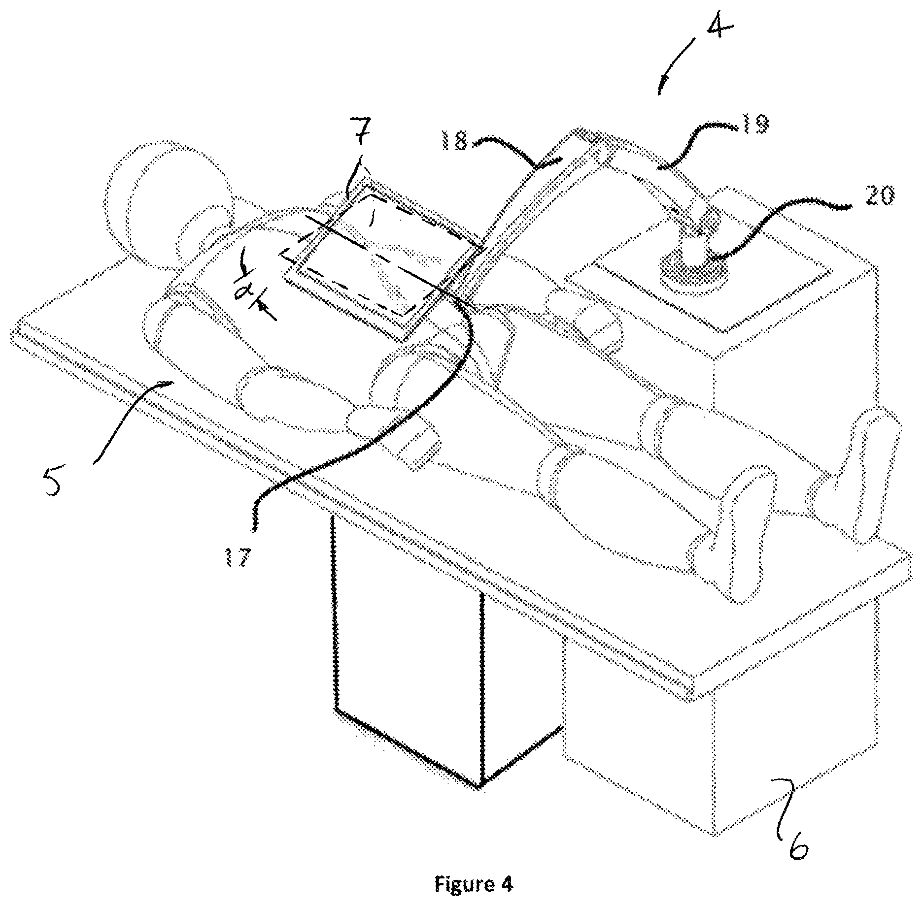
FIG. 4 is an isometric view of an embodiment of the display and support arm positioned next to the patient table.
FIG. 5 is a flow chart describing the basic steps for a minimally invasive procedure using a sensored medical device and the system for displaying a co-aligned image.
DETAILED DESCRIPTION OF THE INVENTION
While preferred embodiments of the present invention have been shown and described herein, it will be obvious to those skilled in the art that such embodiments are provided by way of example only. Numerous variations, changes, and substitutions will now occur to those skilled in the art without departing from the invention. It should be understood that various alternatives to the embodiments of the invention described herein may be employed in practicing the invention. It is intended that the following claims define the scope of the invention and that methods and structures within the scope of these claims and their equivalents be covered thereby.
FIGS. 1-2 describe an embodiment for navigating a minimally invasive medical device within the patient using an acquired three-dimensional anatomical image shown in a display 7 that is substantially aligned to the patient anatomy. A sterile cover may be used to separate the display from the sterile operating field and the sterile cover may incorporate a conductive film to provide a sterile touch interface for a capacitive touch screen display. The sterile display cover may be a flexible, clear drape made of plastic like polyethylene or polyurethane film, a rigid plate made of clear plastic like polycarbonate or acrylic, or a combination of both flexible and rigid plastics. The display is preferably a light-weight, flat LCD display provided by manufacturers like LG Display, Philips, and Innolux or a light-weight, flat OLED display provided by manufacturers like Samsung and Sony. A prime example of such a display would be the NEC TFT color LCD module which provides a usable viewing angle of 85.degree. in all directions. In FIG. 1, the position of the medical device within the patient 5 is provided by an electromagnetic coil sensor located on the distal elongated section of the medical device 1. The position of the sensor is derived through an electromagnetic transmitter 2 similar to those transmitters supplied commercially by NDI and Ascension Technology Corporation. Alternatively, the position of the medical device may be derived from an optical fiber position sensor like that supplied by Luna Innovations. A similar patient reference sensor 3 is placed on the patient in a reliably stable position like the outcropping of the pelvic bone, sternum or clavicle. The reference sensor or sensors provide frequently updated data describing the position of the patient anatomy in the same coordinate system as the medical device sensor. The patch holding the patient sensor may be placed on the patient before the patient's anatomy of interest is imaged and the patch may contain known X-ray visible materials such as tungsten, platinum-iridium, platinum, barium sulfide or iodine and MR visible materials such as gadolinium or vitamin E. The patch is visible within the image of the anatomy and therefore the patient reference sensor 3 can be registered to the three dimensional anatomical image. Position data from the sensor in the medical device 1 and patient reference sensor 3 and display support arm 4 are sent to the system processor 6. The local coordinate systems of the medical device sensor 1 and display 7 may undergo a coordinate system transformation in the system processor so that the positions of the device sensor, patient sensor, and display may be evaluated in a single world coordinate system. Display 7 has a user input button 8. FIG. 2 shows the flow of sensor position data from the sensor buffer 9 to the system processor 10 where the position sensor data is used by the processor to place an icon of the medical device into the three-dimensional patient anatomy image for display through the system display 11. The system processor is a standard computing system like those supplied by Dell or Hewlett Packard running an operating system like Windows or Linux. Position data from the system display and support arm is likewise used by the system processor to orient the image on the screen so that the image, based on display position data from the display 7 and support arm 4 and patient position data from the patient reference sensor 3, is substantially aligned with the patient anatomy. Display position data may also be used to modify the image in the display, for example zooming or clipping the image as the display moves closer to the patient. Other image modifications may include changing transparency, removing layers, removing anatomical structures, or changing colors. Additionally, scaling of the image in discrete steps or image modifications may be done via a touch sensitive surface on the display.
FIG. 3 shows a movable display 12 positioned over a surgical table showing an image of the patient anatomy. A target 13 may be chosen on the image of the anatomy. A remote electromagnetic transmitter, such as those commercially available from Northern Digital Incorporated (NDI) and Ascension Technology Corporation, is positioned near or under the table to localize sensors 15 on at least one medical device 16. As the display is moved, the image of the anatomy, the medical devices, projected the path 14 of the medical devices, and the collision boundaries of the medical devices is repositioned to provide the optimum view for navigation of the medical device within the anatomical image. The access points may be chosen to optimize the ability of the medical devices to reach the anatomical target without creating collisions of the medical devices that are internal and external to the patient and to optimize the ability of the medical devices to reach the target anatomy without intersecting other anatomical structures. Software may be employed to present the collision-free projected path to the anatomical target in an intuitively obvious manner by, for example, showing free path as a green line and a path with collisions as a red line.
FIG. 4 presents an embodiment of the display and support arm with counterbalanced joints at the support arm elbow 18, and shoulder 19. An additional rotational or linear joint is provided at the base of the shoulder 20 to allow the display to move along the inferior to superior axis of the patient. All support arm joints may be encoded to provide data describing the position of the display. The display support is shown in an embodiment where the arm is mounted to a portable cart that is positioned next to the patient table. Axis 17 allows the display to rotate. An alternate embodiment may attach to the table or imaging system.
FIG. 5 provides an overview of the procedure flow for a minimally invasive procedure using a stored image for navigation. The patient anatomy is scanned 21 with a non-invasive imaging modality like CT, MR, or rotational angiography. The imaged anatomy is stored and segmented into a three dimensional image, and borders and centerlines of anatomical structures are calculated using commercially available software from vendors like Philips, Siemens, GE, Toshiba, Terra Recon, Calgary Scientific, Materialise, or Osirix. The image is transferred to the memory of the system processor and the image is registered 22 to the system coordinate system along with the patient and the medical device sensors. Registration of the image may be done by imaging the patient with an image-visible skin patch, by touching a sensored probe to prominent bony an antomical points, or with an externally anatomical marker placed on the patient. At least three separate points of the patch are visible in the image and then a position sensor is placed into the patch. The visible points on the patch or bones may be selected on the displayed image and then the known distance from the marker is used to register the image to the patient position sensor. The patient position sensor and medical device position sensor are inherently registered because their positions are determined by the same sensing system. Next, the registered image is shown 23 above the patient in a manner substantially aligned to the patient anatomy. The image position may be biased slightly toward the user to provide improved ergonomics. For example, if the user is on the right side of the patient, the user may press a button on the display touch screen to inform the system of the user's operating position. The system processor will then bias the image rotationally by a small amount, usually by and angle .alpha. of 15-30 degrees (FIG. 4), toward the user. The system may also bias rotational scaling in the user's direction, creating a rotation scale factor that increases slightly as the display is moved rotationally away from the user. In this way, the image is biased toward ergonomically comfortable viewing positions for the user without losing the substantial alignment of the image to the patient that provides for improved perception and usability. The medical device may be navigated 24 within or near the patient as the position sensor in the medical device is tracked and presented as an image icon within the image of the patient anatomy. The image of the anatomy and the image of the medical device may be shown with varying degrees of transparency to maximize the visibility of the device and anatomical images. The display, showing the image of the medical device within the image of the anatomy, may be repositioned 25 to enhance the viewing angle of the anatomy. As the display is moved, the image on the screen is updated to maintain substantial alignment between the displayed anatomical image and the patient anatomy.
* * * * *
References
D00000
D00001
D00002
D00003
D00004
XML
uspto.report is an independent third-party trademark research tool that is not affiliated, endorsed, or sponsored by the United States Patent and Trademark Office (USPTO) or any other governmental organization. The information provided by uspto.report is based on publicly available data at the time of writing and is intended for informational purposes only.
While we strive to provide accurate and up-to-date information, we do not guarantee the accuracy, completeness, reliability, or suitability of the information displayed on this site. The use of this site is at your own risk. Any reliance you place on such information is therefore strictly at your own risk.
All official trademark data, including owner information, should be verified by visiting the official USPTO website at www.uspto.gov. This site is not intended to replace professional legal advice and should not be used as a substitute for consulting with a legal professional who is knowledgeable about trademark law.