Microsurgical Tool For Robotic Applications
Bovay; Loic Alexandre ; et al.
U.S. patent application number 16/855786 was filed with the patent office on 2020-10-08 for microsurgical tool for robotic applications. The applicant listed for this patent is Auris Health, Inc.. Invention is credited to Loic Alexandre Bovay, Allen Jiang, Fernando Reyes, Travis Schuh.
| Application Number | 20200315717 16/855786 |
| Document ID | / |
| Family ID | 1000004901487 |
| Filed Date | 2020-10-08 |


View All Diagrams
| United States Patent Application | 20200315717 |
| Kind Code | A1 |
| Bovay; Loic Alexandre ; et al. | October 8, 2020 |
MICROSURGICAL TOOL FOR ROBOTIC APPLICATIONS
Abstract
The disclosed technology includes improved microsurgical tools providing multiple degrees of freedom at the wrist level, including roll, pitch, and grasp DOFs, a tight articulation bending radius, low radial offset, and improved stiffness. Some implementations include an end effector platform moveable along a fixed trajectory on a fictional axle so as not to interfere with a central-axis aligned working channel; a crossed-arm mechanical linkage for articulating an end-effector platform throughout a pitch DOF with an amplified pitch angle; and a partial pulley system to articulate the arms while maximizing pulley radius to shaft diameter, and permitting a constant transmission efficiency to the arms throughout the range of articulation. In some implementations, a tool shaft outer diameter may be smaller than 3 mm; a pitch DOF range may be .+-.90.degree., a roll DOF range may be .+-.180.degree., and a grasp DOF range may be 30.degree..
| Inventors: | Bovay; Loic Alexandre; (Pully, CH) ; Schuh; Travis; (Los Altos, CA) ; Reyes; Fernando; (Daly City, CA) ; Jiang; Allen; (Fremont, CA) | ||||||||||
| Applicant: |
|
||||||||||
|---|---|---|---|---|---|---|---|---|---|---|---|
| Family ID: | 1000004901487 | ||||||||||
| Appl. No.: | 16/855786 | ||||||||||
| Filed: | April 22, 2020 |
Related U.S. Patent Documents
| Application Number | Filing Date | Patent Number | ||
|---|---|---|---|---|
| 15435790 | Feb 17, 2017 | 10639109 | ||
| 16855786 | ||||
| 15089406 | Apr 1, 2016 | |||
| 15435790 | ||||
| 62141817 | Apr 1, 2015 | |||
| Current U.S. Class: | 1/1 |
| Current CPC Class: | A61B 34/72 20160201; A61B 34/30 20160201; A61B 2034/305 20160201; A61B 2017/2912 20130101; A61B 34/71 20160201; A61B 17/2909 20130101; A61B 2017/2929 20130101; A61B 17/2804 20130101; A61B 2034/304 20160201; A61B 2017/2927 20130101 |
| International Class: | A61B 34/30 20060101 A61B034/30; A61B 17/28 20060101 A61B017/28; A61B 34/00 20060101 A61B034/00; A61B 17/29 20060101 A61B017/29 |
Claims
1. A microsurgical tool, comprising: an elongated body having a distal end; a platform moveably coupled to the distal end of the elongated body; and a linkage coupling the distal end of the elongated body to the platform to allow the platform to move relative thereto, wherein the linkage comprises: a first arm operatively coupled to the distal end of the elongated body at a first proximal hinge and to the platform at a first distal hinge, the first arm having a first redirect surface, and a first force transfer element disposed around the first redirect surface before coupling to the first arm such that pulling the first force transfer element pivots the first arm about the first proximal hinge with a first amplified range of motion.
2. The microsurgical tool of claim 1, wherein the linkage further comprises: a second arm operatively coupled to the distal end of the elongated body at a second proximal hinge and to the platform at a second distal hinge, the second arm having a second redirect surface, and a second force transfer element disposed around the second redirect surface before coupling to the second arm such that pulling the second force transfer element pivots the second arm about the second proximal hinge with a second amplified range of motion.
3. The microsurgical tool of claim 2, wherein the first and second arms are crossed with respect to one another.
4. The microsurgical tool of claim 2, wherein the first and second arms form a mechanical linkage for moving the first arm with a constant transmission efficiency between the mechanical linkage and the first arm throughout a range of movement of the first arm.
5. The microsurgical tool of claim 2, wherein the first and second amplified ranges of motion are of the same magnitude in opposite directions.
6. The microsurgical tool of claim 2, wherein the first proximal hinge and the second proximal hinge are co-axial.
7. The microsurgical tool of claim 2, wherein the first distal hinge and the second distal hinge are coupled to diametrically opposite positions on the platform.
8. The microsurgical tool of claim 1, wherein the first force transfer element comprises a pull wire.
9. The microsurgical tool of claim 1, wherein the first force transfer element and the first redirect surface of the first arm form a partial pulley to provide the first amplified range of motion.
10. The microsurgical tool of claim 1, wherein the first amplified range of motion is in a pitch degree of freedom.
11. The microsurgical tool of claim 1, wherein the first redirect surface of the first arm comprises a first semicircular portion.
12. The microsurgical tool of claim 11, wherein the first semicircular portion is concentric with the first proximal hinge.
13. The microsurgical tool of claim 1, wherein the first force transfer element is coupled to a first bore of the first arm, wherein the first bore is offset from a first line formed between the first proximal hinge and the first distal hinge.
14. The microsurgical tool of claim 1, further comprising an end effector operatively coupled to the platform.
15. The microsurgical tool of claim 14, wherein the end effector comprises a grasper.
16. The microsurgical tool of claim 14, wherein the end effector comprises at least one jaw, and further comprising a first tendon coupled to the at least one jaw and tensionable to move the at least one jaw, providing the at least one jaw with a grasping degree of freedom.
17. The microsurgical tool of claim 16, wherein the tendon is disposed at least partially within the elongated body.
18. The microsurgical tool of claim 14, further comprising a torque coil operatively coupled to the end effector to provide the end effector with a roll degree of freedom.
19. The microsurgical tool of claim 18, wherein one or more of the elongated body and the platform comprise a channel through which the torque coil is disposed.
20. The microsurgical tool of claim 1, wherein the elongated body has a centerline, and wherein the first proximal hinge is offset from the centerline.
Description
CROSS-REFERENCE
[0001] This application is a continuation of U.S. patent application Ser. No. 15/089,406, filed Apr. 1, 2016, which claims the benefit of U.S. Provisional Application No. 62/141,817, filed Apr. 1, 2015, which applications are incorporated herein by reference.
BACKGROUND
[0002] Surgeries can be long and tedious procedures requiring intense focus and high accuracy from a surgeon. To help surgeons stay at the best of their abilities, it is important to consider a surgeon's comfort and keep fatigue to a minimum during a surgical procedure. To this end, robots can help sustain a surgeon's functionality and performance over extended periods of time. Moreover, robots may provide effective tools to increase the surgeon's capability and efficiency beyond levels sustainable with manual tools.
[0003] Some advantages provided by robotics in surgery include: allowing the surgeon to operate more comfortably to lessen strain and tiredness; providing better visualization of an operating area; allowing manipulation of tools exceeding manual dexterity; providing greater steadiness and accuracy; enabling teleoperation; and facilitating shorter procedure times, thus lowering costs for providers and patients. Some of these advantages are especially important for successful minimal invasive surgery (MIS) and microsurgery, where dexterity, access, and good vision are paramount.
[0004] Conventional robots and surgical tools, however, do not effectively maximize these benefits particularly when scaled down to sizes suitable for MIS and microsurgery. For example, some conventional gear-based transmissions have machinability limits. Moreover, gears may interfere with a working channel of a tool where space is at a premium. Conventional pulley-based systems may suffer from a diminishing bending radius when scaled down, and spring-flexure-based systems often lack stiffness. Even tools relying on simple elastic properties of materials may experience exacerbated fatigue issues.
SUMMARY
[0005] Some or all of the above limitations may be addressed by many implementations of the technology disclosed herein. Example implementations include improved tools and devices suitable for MIS and microsurgery robotic applications. Some implementations provide for multiple degrees of freedom ("DOF") at the wrist level, including roll, pitch, and grasp DOFs, while maintaining a tight articulation bending radius.
[0006] According to an example implementation, a microsurgical tool is provided. The microsurgical tool may comprise an elongated body having a centerline and outer diameter at a distal end of the elongated body. The microsurgical tool may further comprise a platform moveably coupled to the distal end of the elongated body. The microsurgical tool may yet further comprise an end effector operatively coupled to the platform and being articulable in at least three degrees of freedom, including a pitch degree of freedom up to a pitch angle of at least .+-.90.degree.. The microsurgical tool may also have a ratio of the outer diameter of the elongated body, to a radial offset of the end effector to the centerline the elongated body, of at least 0.65.
[0007] In an example implementation, the ratio of the outer diameter to the radial offset may be at least 0.83. The microsurgical tool may further comprise a torque coil or flexible tube disposed within the elongated body to transmit torque for articulating the end effector in a roll degree of freedom. The end effector may be repeatedly or infinitely articulable in a roll degree of freedom. The end effector may also be at least one of a grasper, a gripper, forceps, or scissors.
[0008] In another example implementation, the microsurgical may also comprise an actuation tendon disposed within the elongated body. The actuation tendon may be tensionable to actuate the end effector in a grip degree of freedom. The microsurgical tool may also comprise a torque coil disposed within the elongated body to transmit torque for articulating the end effector in a roll degree of freedom with the actuation tendon being disposed within the torque coil.
[0009] In yet another example implementation, the end effector may also comprise a deformable grasper. The end effector may also comprise a unilateral grasper, or a grasper with at least one fixed jaw and one moving jaw. Alternatively, the end effector may comprise at least two opposing jaws articulable to open to an angle of at least about 30.degree. relative to each other.
[0010] According to another example implementation, a microsurgical tool is provided. The microsurgical tool may comprise an elongated body having a proximal end and a distal end. The microsurgical tool may further comprise a platform operatively coupled to an end effector. The microsurgical tool may yet further comprise a first arm operatively coupled to a first proximal hinge and a first distal hinge, and a second arm operatively coupled to a second proximal hinge and a second distal hinge. The first proximal hinge and the second proximal hinge may be coupled to the distal end of the elongated body and the first distal hinge and the second distal hinge may be coupled to the platform. The first arm and the second arm may be moveable to articulate the end effector in a pitch degree of freedom.
[0011] In an example implementation, the end effector may be articulable in a pitch degree of freedom up to a pitch angle of at least about .+-.90.degree.. The microsurgical tool may comprise a mechanical link for amplifying a pitch angle of the platform by a factor A relative to a pitch angle of the first arm or second arm.
[0012] In another example implementation, the first proximal hinge and the second proximal hinge may be coupled to the distal end of the elongated body and the first distal hinge and the second distal hinge may be coupled to the platform such that the first arm and the second arm are crossed. The elongated body may have a centerline and the first proximal hinge may be offset from the centerline. The microsurgical tool may further comprise a mechanical link for moving the first arm with a constant transmission efficiency between the mechanical link and first arm throughout a range of movement of the first arm.
[0013] In yet another example implementation, the microsurgical tool may further comprise a first tendon coupled to the first arm and tensionable to move the first arm. The first arm may be coupled to a first pulley. An axis of the pulley may be concentric with the first proximal hinge. The first pulley may be a partial pulley such that a radius of the pulley not in contact with the first tendon is smaller than a radius of the pulley that is in contact with the first tendon, or such that a profile of the pulley is a sector rather than a full circle. In some implementations, the first pulley may fit within a profile of the elongated body.
[0014] Other implementations, features, and aspects of the disclosed technology are described in detail herein and are considered a part of the claimed disclosed technology. Other implementations, features, and aspects may be understood with reference to the following detailed description, accompanying drawings, and claims.
INCORPORATION BY REFERENCE
[0015] All publications, patents, and patent applications mentioned in this specification are herein incorporated by reference to the same extent as if each individual publication, patent, or patent application was specifically and individually indicated to be incorporated by reference.
BRIEF DESCRIPTION OF THE DRAWINGS
[0016] The novel features of the disclosed technology are set forth with particularity in the appended claims. A better understanding of the features and advantages of the present technology will be obtained by reference to the following detailed description that sets forth illustrative implementations, in which the principles of the technology are utilized, and the accompanying drawings of which:
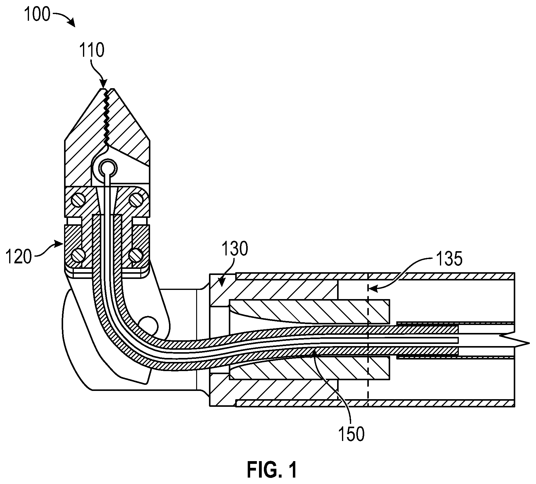
[0017] FIG. 1 depicts an illustration of a microsurgery tool 100, according to an example implementation.
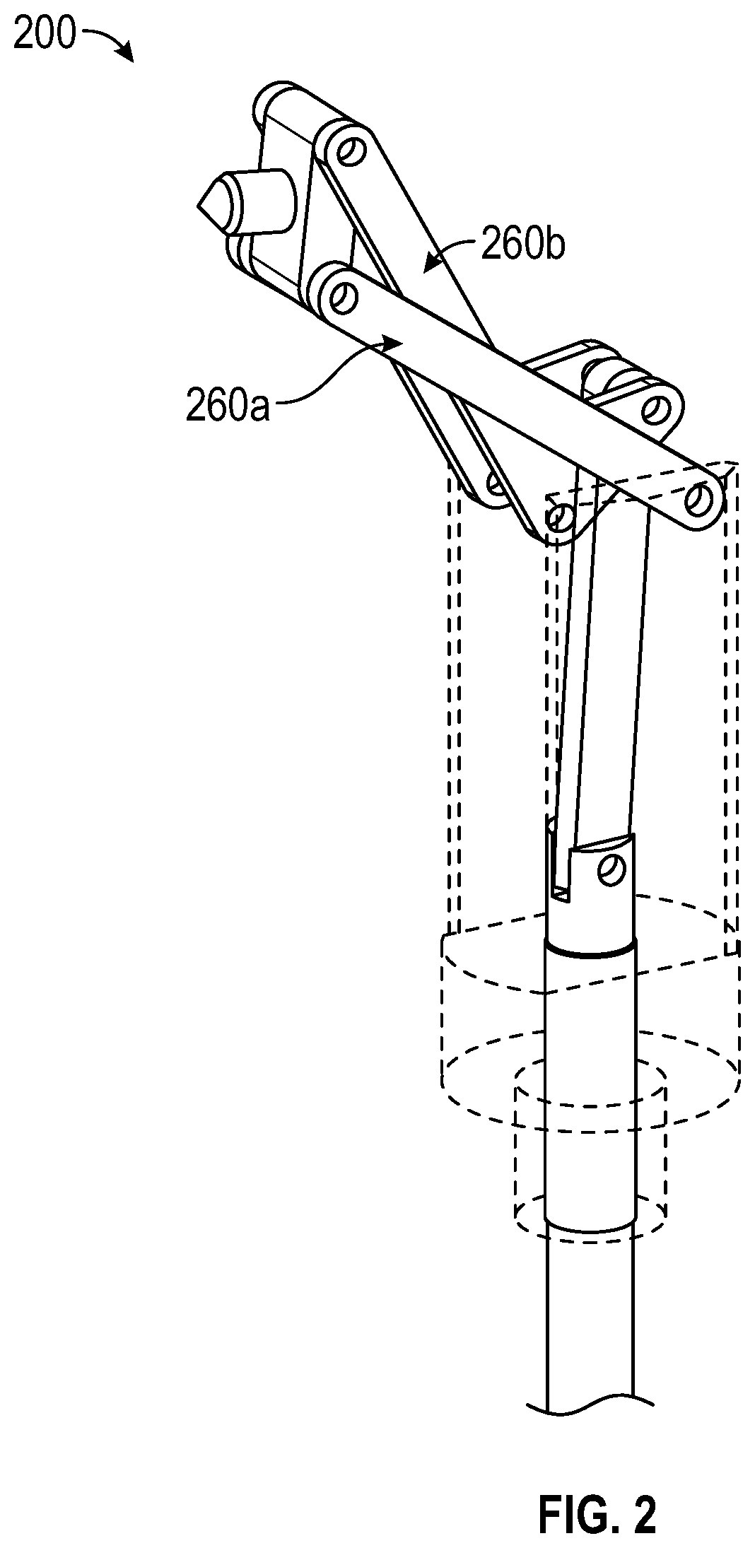
[0018] FIG. 2 depicts an illustration of a crossed-arm linkage 200 for articulating a platform, according to an example implementation.
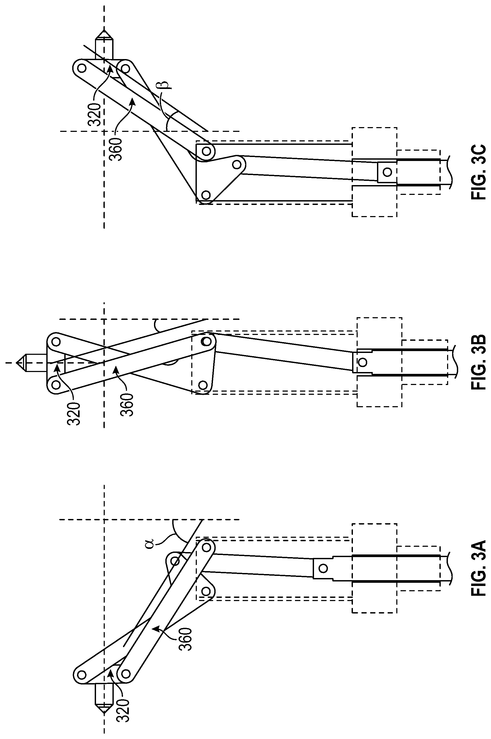
[0019] FIGS. 3A, 3B, and 3C depict illustrations of the platform 320 being articulated from -90.degree. to +90.degree. using a crossed-arm linkage, according to an example implementation.
[0020] FIG. 4 depicts an illustration of a geometrical model 400 of the articulation 460 of the crossed-arm linkage 200, according to an example implementation.
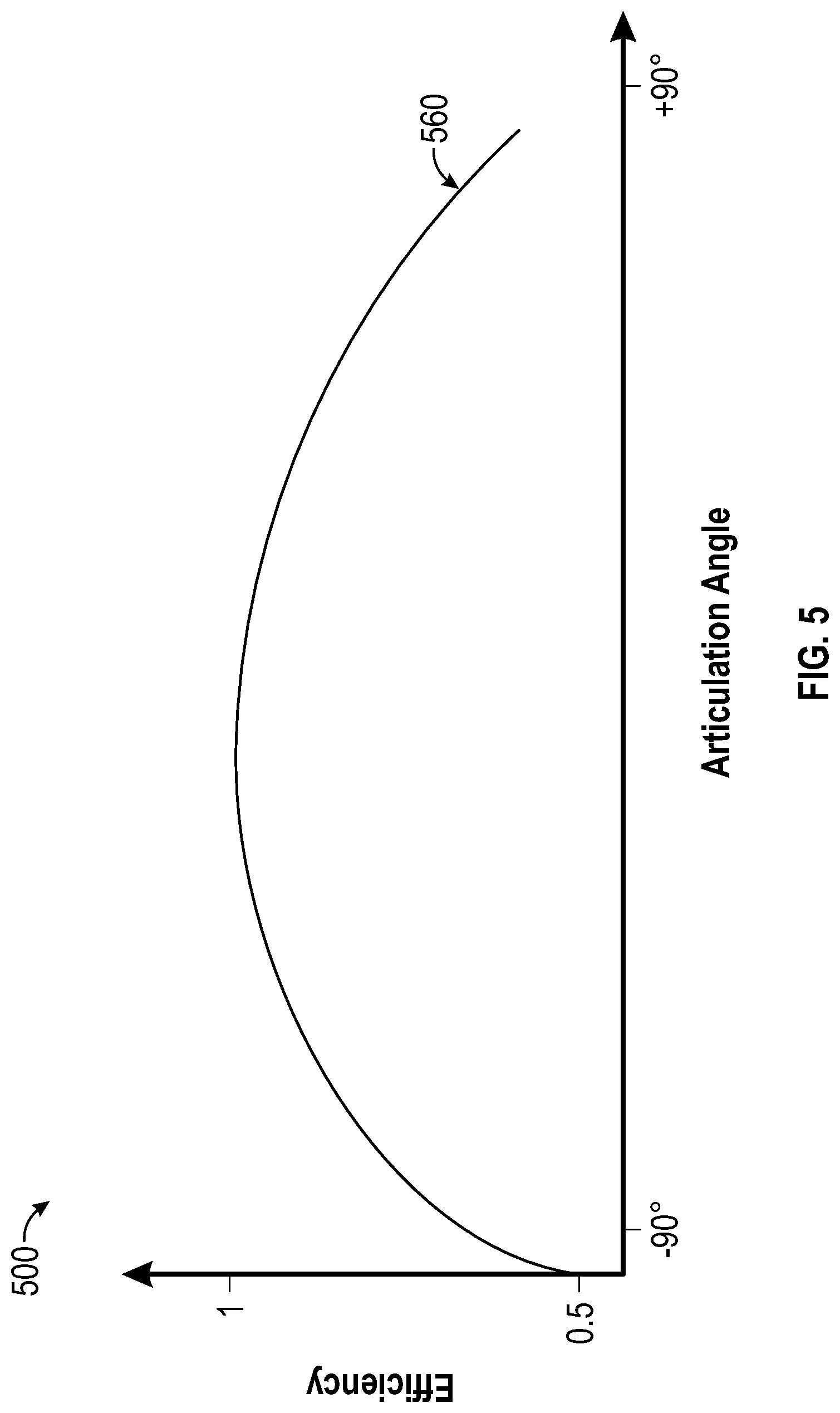
[0021] FIG. 5 depicts an illustration of an efficiency plot 500 corresponding to the articulation of the crossed-arm linkage 200, according to an example implementation.
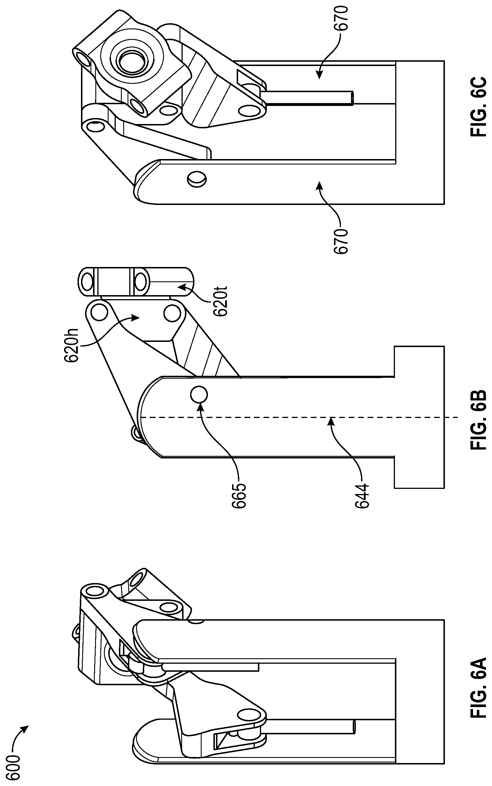
[0022] FIGS. 6A, 6B, and 6C depict illustrations of another crossed-arm linkage 600, according to an example implementation.
[0023] FIG. 7 depicts an illustration of the platform assembly 700, according to an example implementation.
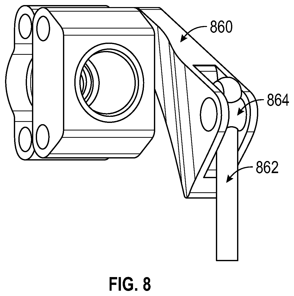
[0024] FIG. 8 depicts an illustration of a pull-wire attachment for articulating an arm, according to an example implementation.
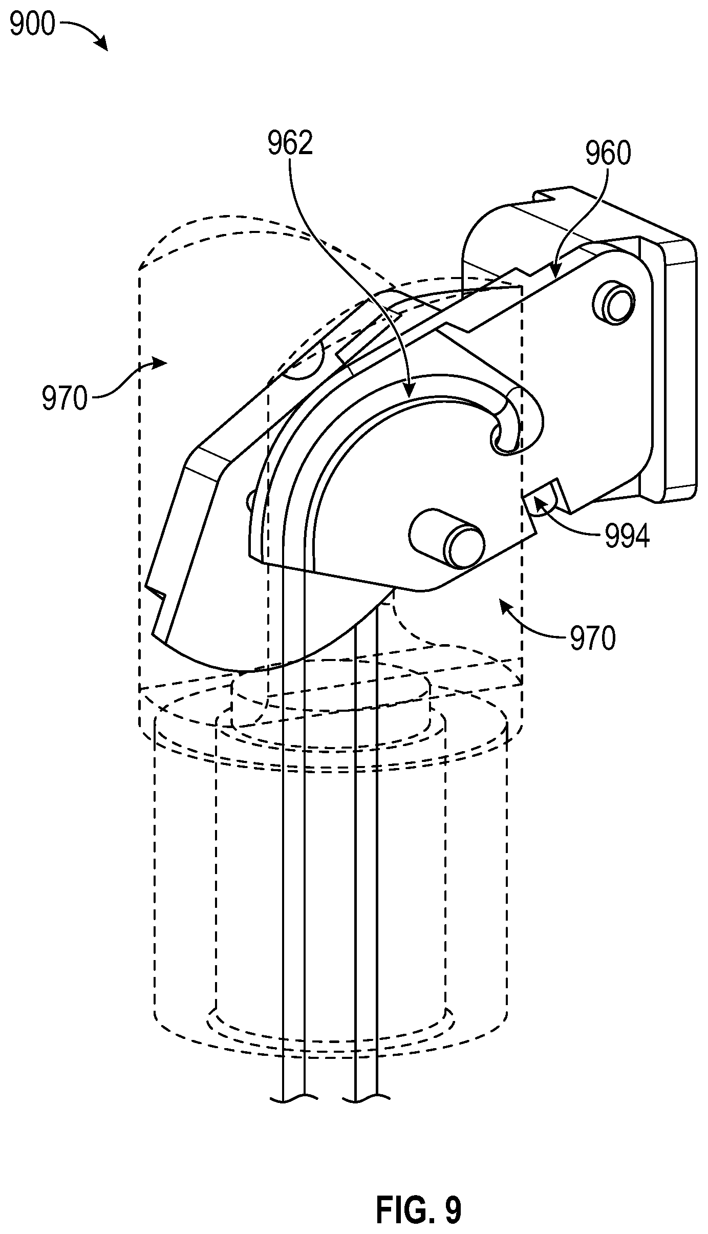
[0025] FIG. 9 depicts an illustration of yet another cross-armed linkage 900, according to an example implementation.
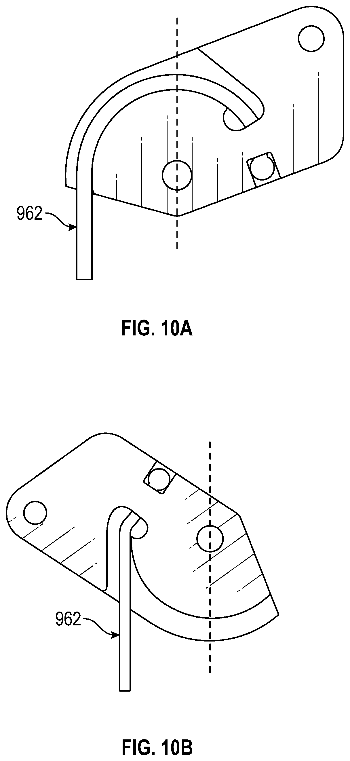
[0026] FIGS. 10A and 10B depict illustrations of a platform arm being articulated by a pull wire, according to an example implementation.
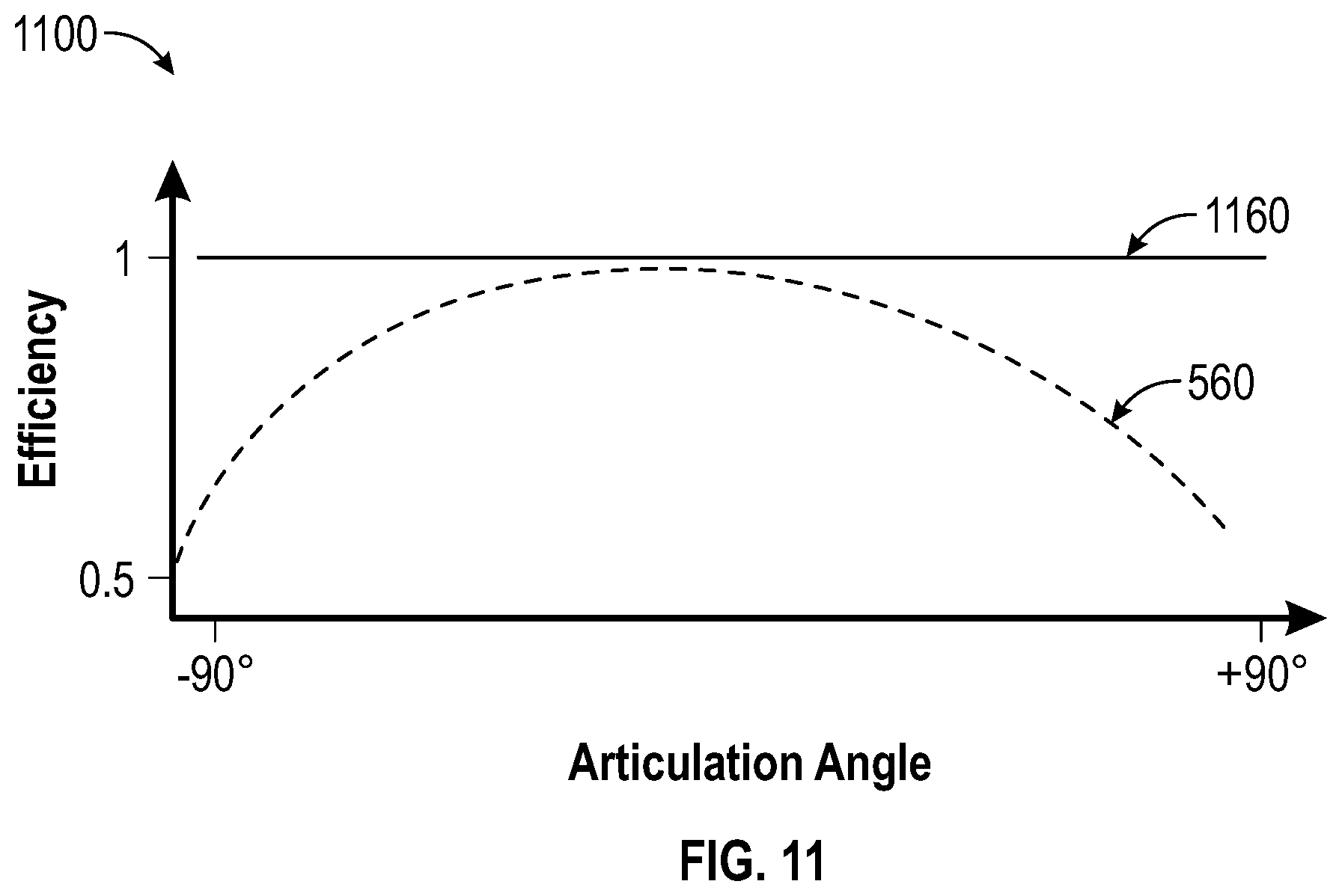
[0027] FIG. 11 depicts an illustration of an efficiency plot 1100 corresponding to the articulation of the crossed-arm linkage of 600, according to an example implementation.
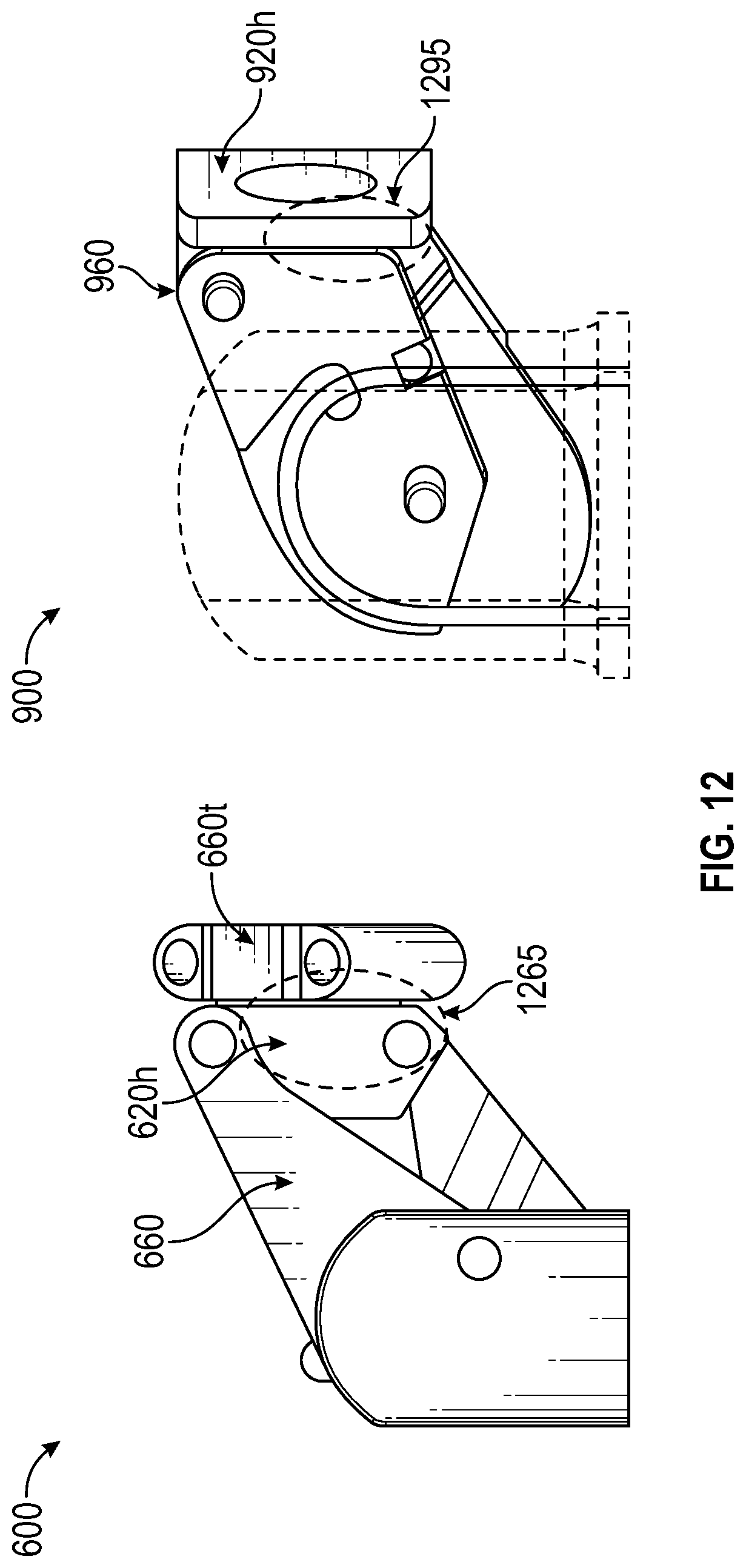
[0028] FIG. 12 depicts an illustration of the difference in arm to platform overlap between linkages 600 and 900.
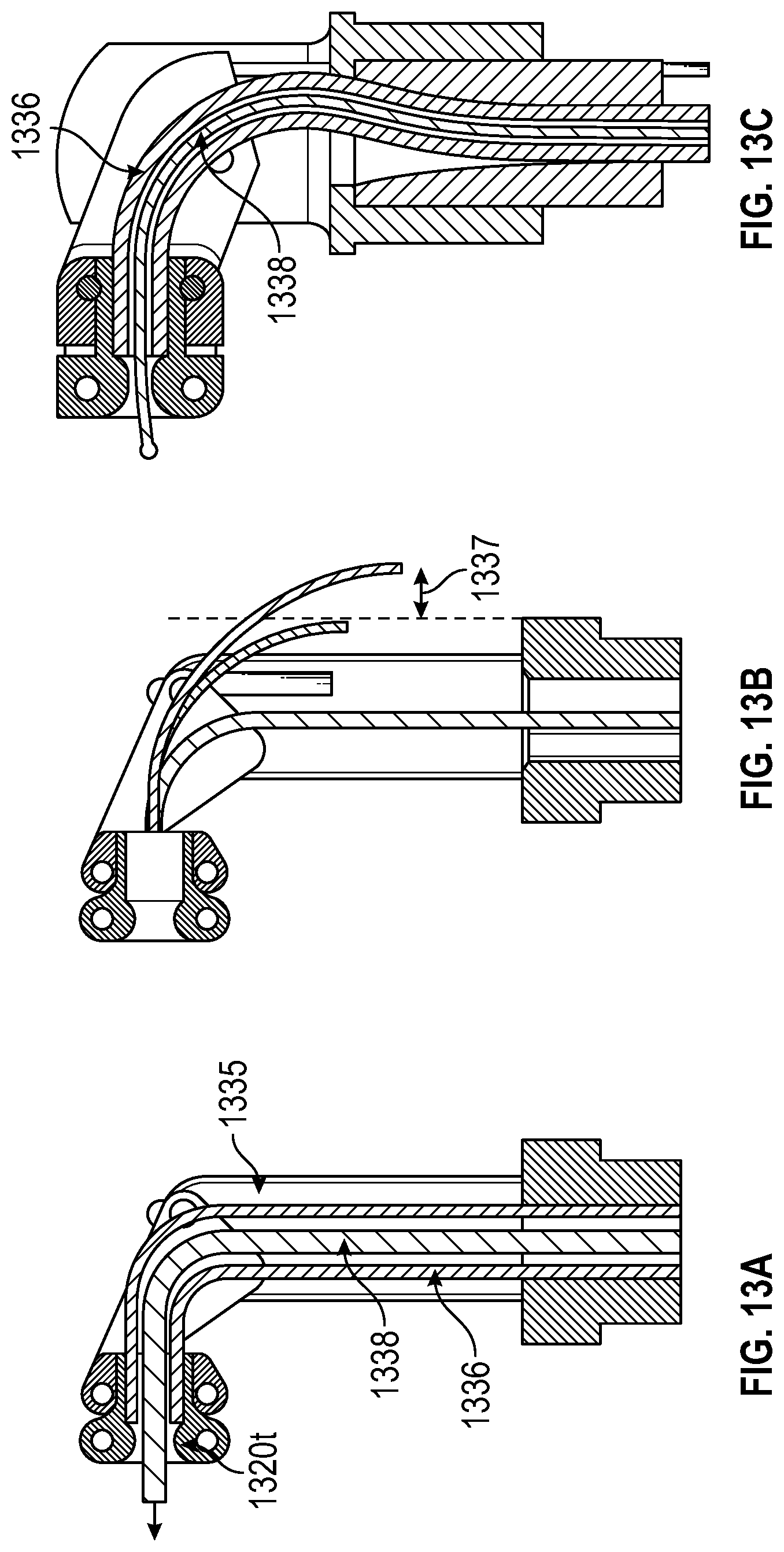
[0029] FIG. 13A depicts an illustration of a torque coil actuation mechanism, according to an example implementation.
[0030] FIG. 13B depicts an illustration of torque coil overshoot, according to an example implementation.
[0031] FIG. 13C depicts an illustration of a torque coil with a greater bending radius than the microsurgical tool, according to an example implementation.
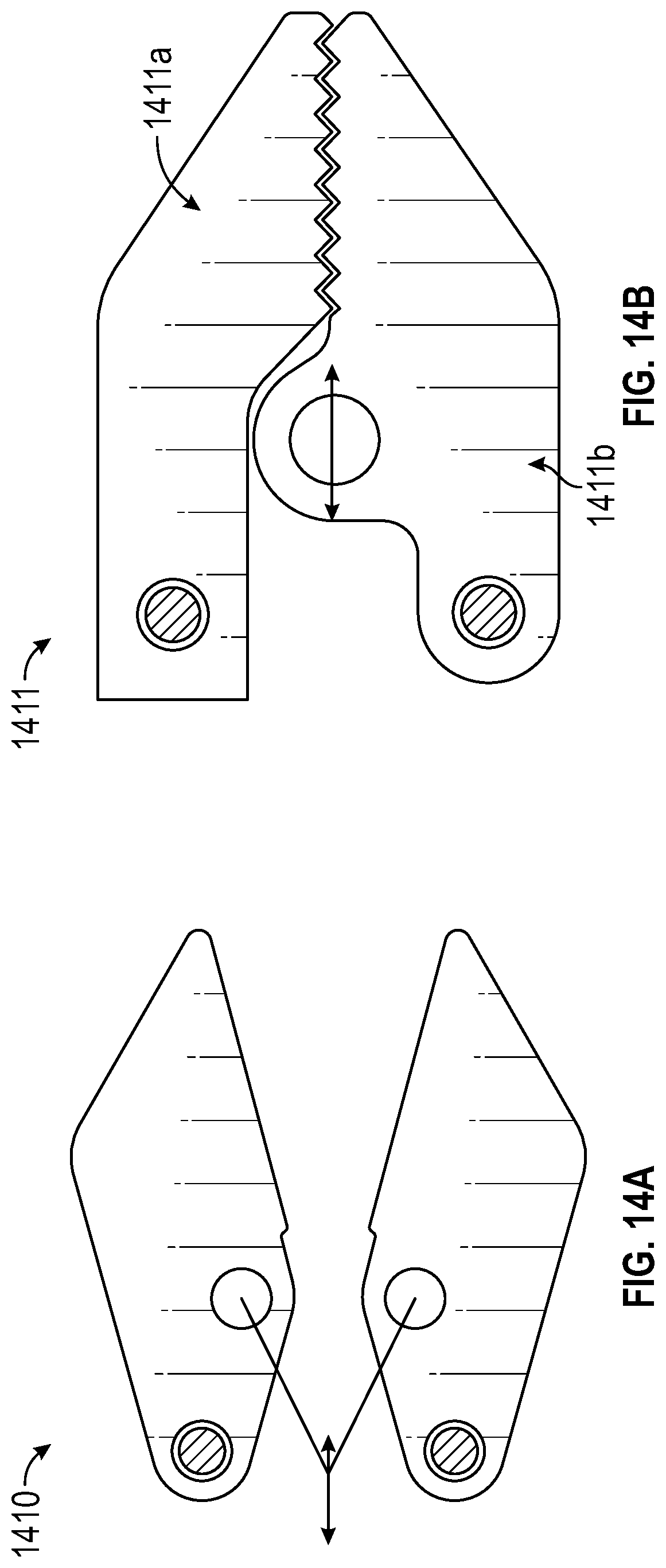
[0032] FIG. 14A depicts an illustration of a bilateral grasper 1410, according to an example implementation.
[0033] FIG. 14B depicts an illustration of a unilateral grasper 1411, according to an example implementation.
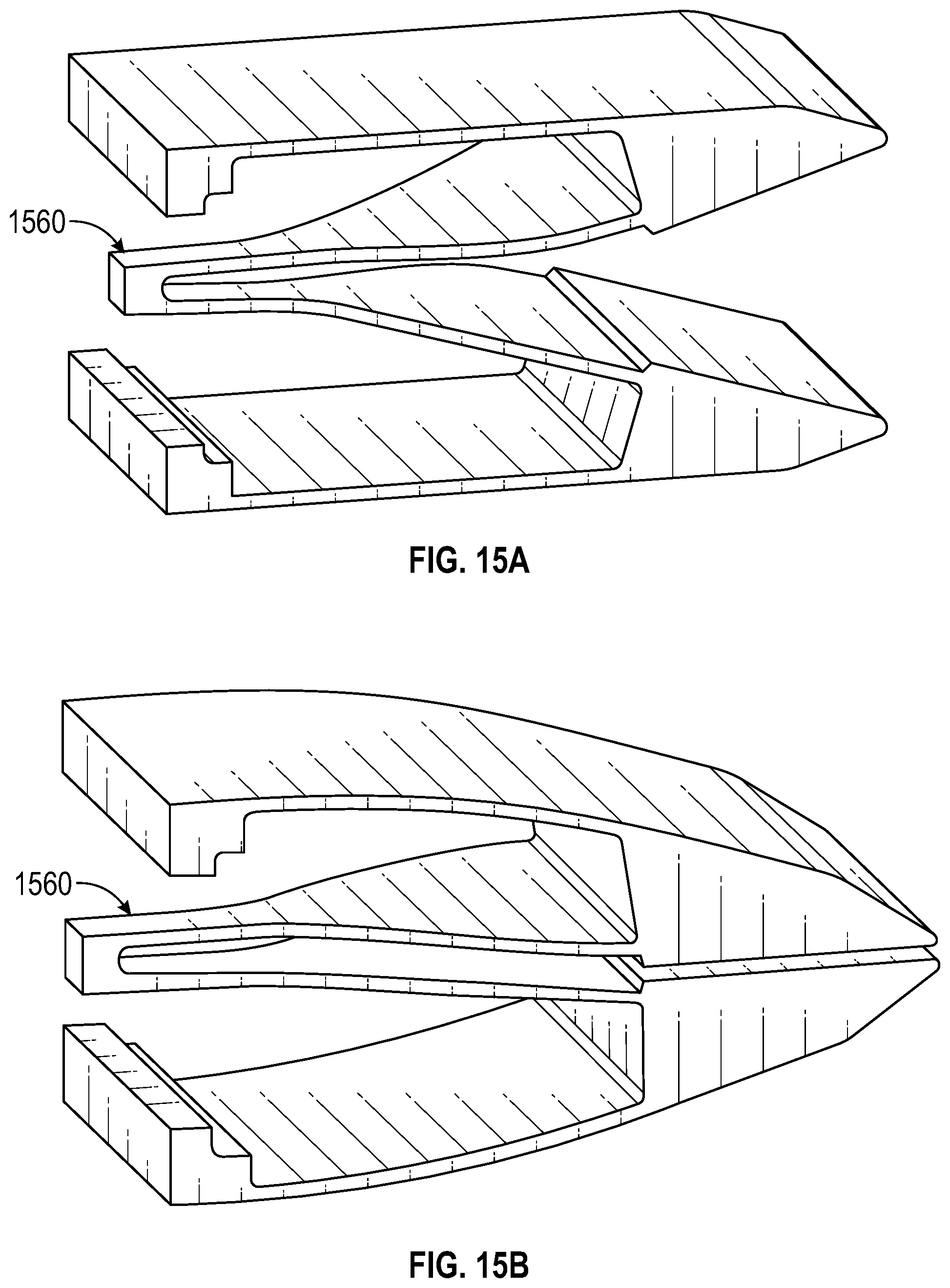
[0034] FIGS. 15A and 15B depict illustrations of a deformable grasper, according to an example implementation.
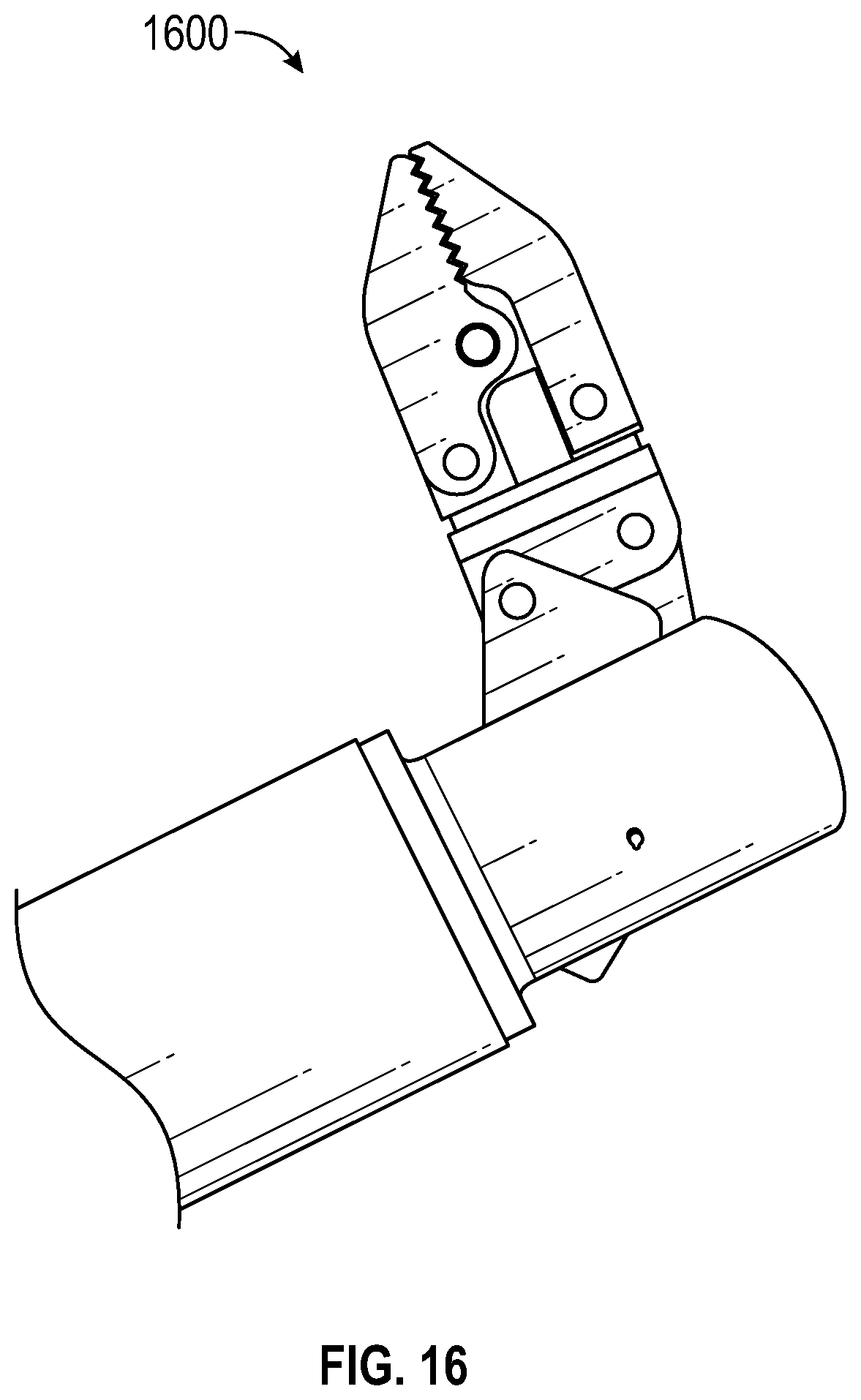
[0035] FIG. 16 depicts an illustration of a microsurgical tool 1600 incorporating linkage 900, according to an example implementation.
[0036] FIG. 17 depicts an illustration of a first profile of the microsurgical tool 1600, according to an example implementation.
[0037] FIG. 18 depicts an illustration of a second profile of the microsurgical tool 1600, according to an example implementation.
DETAILED DESCRIPTION
[0038] To facilitate an understanding of the principles and features of implementations of the disclosed technology, various example implementations are explained below. Although some implementations of the disclosed technology are explained in detail, other implementations are contemplated. Further, in describing example implementations, specific terminology will be resorted to for the sake of clarity. It is not intended that the disclosed technology be limited in scope to the details of construction and arrangement of components set forth in the following description or illustrated in the drawings. Rather, the disclosed technology is capable of other implementations and of being practiced or carried out in various ways.
[0039] Throughout the specification and the claims, the following terms take at least the meanings explicitly associated herein, unless the context clearly dictates otherwise. The term "coupled" means that one function, feature, structure, or characteristic is directly or indirectly joined to or in communication with another function, feature, structure, or characteristic. Relational terms such as "first" and "second," and the like may be used solely to distinguish one entity or action from another entity or action without necessarily requiring or implying any actual such relationship or order between such entities or actions. The term "or" is intended to mean an inclusive "or." Further, the terms "a," "an," and "the" are intended to mean one or more unless specified otherwise or clear from the context to be directed to a singular form. The term "include" and its various forms are intended to mean including but not limited to.
[0040] Although example implementations are described herein in the context of robotic applications, one of skill in the art will appreciate that the disclosed technology may be applicable to manually operated tools and surgeries. Moreover, although various crossed-arm linkages are described in detail, one of skill in the art will appreciate that other mechanical links and actuators may be used in place of or in addition to parts and components described herein.
[0041] Many implementations of the disclosed technology include improved microsurgical tools, instruments, and devices for robotic applications. Some implementations provide multiple degrees of freedom ("DOF") at the wrist level, including roll, pitch, and grasp DOFs, a tight articulation bending radius, low radial offset, or improved stiffness. These features may afford various benefits. For example, a reduced outer diameter can promote less scarring and quicker recovery; compact articulations and a tight bending radius may aid working in confined spaces; a versatile platform can increase the capabilities of the surgical tool; multiple DOF and high ranges of articulation can improve dexterity and reachability; a stiff tool shaft and small radial offset may preserve the line of sight of operation; and torsional stiffness can reduce backlash and improve consistency.
[0042] To these ends, the present disclosure introduces a robust but versatile platform assembly for end-effector coupling, the platform being moveable along a fixed trajectory on a fictional axle so as not to interfere with a center-axis-aligned working channel; a crossed-arm mechanical linkage for articulating an end-effector platform throughout a pitch DOF with an amplified pitch angle; and a partial pulley system to articulate the linkage arms while maximizing pulley radius to tool shaft diameter, and permitting a constant transmission efficiency to the arms throughout the range of articulation.
[0043] According to many implementations, a tool shaft outer diameter may be smaller than 3 mm; and at the wrist-level, a pitch DOF range may be at least .+-.90.degree., a roll DOF range may be at least .+-.180.degree., and a grasp DOF range may be at least 30.degree.. The platform may be operatively coupled to one or more end effectors, including but not limited to, graspers, bipolar grippers, biopsy graspers, needle drivers, irrigation and suction pipes, needles, lasers, and force sensors.
[0044] Referring now to the figures, in which like reference numerals represent like parts throughout the views, these and other features of the disclosed technology will be described in detail.
[0045] FIG. 1 depicts an illustration of a microsurgery tool 100, according to an example implementation. As shown in FIG. 1, the tool may comprise a shaft 130 or elongated body, and a platform 120 or platform assembly moveably coupled to an end of the shaft. The platform may support or be coupled to an end effector 110 such as a grasper, as shown. The platform or end effector may be articulable at a "wrist" of the tool near the end of the body. The shaft may have an outer diameter 135, and an inner diameter circumscribing a working channel 150 of the tool. The inner channel may contain tendons, actuators, or other mechanisms for articulating the platform or end effector.
[0046] MIS procedures typically rely on small punctures to access an operation area. It can be beneficial to keep these punctures as small as possible to shorten hospital stay and scarring. A related challenge is augmenting dexterity. It can be beneficial to have more DOFs at the wrist level of a tool in order to reach more areas once inside a patient's body. Increased dexterity and reduced size are often tradeoffs. Many implementations of the disclosed technology, however, seek to maximize these benefits, by reducing a tool outer diameter while providing improved capability, such as multiple DOF and increased grip strength.
[0047] Accordingly, a significant design objective was to provide multiple DOF at robust ranges while minimizing or reducing the surgical tool shaft and radial offset, which correspond to the bending radius. As used herein, the radial offset may refer to how far the end effector or another tip of the tool radially extends from a shaft axis.
[0048] According to many implementations, mechanical links may be used to transmit power to the platform 120 or end effector 110. The type of links or linkage geometry may be configured to minimize or reduce backlash and to maximize or improve a stiffness of transmission. These two features are often significant in providing good control and feeling when using a microsurgical tool.
[0049] FIG. 2 depicts an illustration of a crossed-arm linkage 200 for articulating a platform, according to an example implementation. To articulate the platform in a pitch DOF, a compliant hinge or linkage was provided based on crossing arms 260a and 260b. In some implementations, the linkage may act as an amplifier between the pitch angle of the arms and the platform or end effector. For example, when the arms travel a range of R.sub.arms degrees, the platform may move over a range of AR.sub.arms with A being the amplification factor. This amplification factor may be tuned by altering the geometrical properties of the linkage.
[0050] FIGS. 3A, 3B, and 3C depict illustrations of the platform 320 being articulated from -90.degree. to +90.degree. using a crossed-arm linkage, according to an example implementation. In FIG. 3A, the platform is at an angle of -90.degree. and a first arm 310 is at an angle .alpha. of -58.degree.. In FIG. 3C, the platform is at an angle of +90.degree. and the first arm 310 is at an angle .alpha. of -33.degree.. Thus, although the platform traverses a range of 180.degree., the arm may travel only from a range of 91.degree..
[0051] FIG. 4 depicts an illustration of a geometrical model 400 of the articulation 460 of the crossed-arm linkage 200, according to an example implementation. Even taking into account a change in pitch angle of both arms (e.g., by averaging the pitch angles of the first and second arms) the clear reduction in required arm rotation range permitted by the crossed-arm linkage may reduce the shaft and radial offset of the tool.
[0052] FIGS. 6A, 6B, and 6C depict illustrations of another crossed-arm linkage 600, according to an example implementation. To accommodate a roll DOF, a second crossed-arm linkage was provided that opens up a center channel of the tool between base walls 670 for a roll actuation mechanism. In order to free up space around the central axis, two of the four arms were removed over linkage 200 and a two-part platform assembly was provided that would allow a tip 620t of the assembly to rotate freely inside of the head 620h. As shown in FIG. 6B, a respective proximal hinge 665 of the arms may be offset from a centerline 644 of the shaft.
[0053] FIG. 7 depicts an illustration of the platform assembly 700, according to an example implementation. In some implementations, two pins may interface 722 with a grove in the tip 620b to hold it axially while allowing rotation. A washer 724 may be added to provide a smooth surface to limit friction when the parts are axially pushed together. When the parts are axially pulled apart, the pin and grove interface may be relied on to provide smooth rotation. Varying washer thickness may help achieve an improved balance between backlash and friction.
[0054] With the center axis opened up, various mechanical mechanism were evaluated for adding a roll DOF at the tip. According to many implementations, a torque coil may be used to transmit torque for articulating a tip of the platform assembly or an end effector in a roll DOF. In another implementation, a laser-cut highly flexible tube may be used.
[0055] FIG. 13A depicts an illustration of a torque coil actuation mechanism, according to an example implementation. As shown in FIG. 13A, a torque coil 1336 may be disposed within an inner diameter of the shaft 1335.
[0056] FIG. 13A depicts an illustration of a torque coil actuation mechanism, according to an example implementation. As shown in FIG. 13A, a torque coil 1336 may be disposed within an inner diameter of the shaft 1335. In some implementations, a tendon or other actuation mechanisms may be further disposed within the torque coil itself, for example, tendon 1320 for opening and closing a grasper, as shown in FIGS. 13A and 13C.
[0057] It was experimentally determined that two-layer torque coils as used in these implementations may transmit torque in an asymmetrical way, whereas three-layer torque coils may transmit torque symmetrically in both directions. Each of the tested specimens also surpassed the flexure grasper torque.
[0058] FIG. 13B depicts an illustration of torque coil overshoot, according to an example implementation. It was determined that a yield bending radius of the torque coil may be a limiting factor to the bending radius of the tool. However, as shown in FIG. 13B, open space in the back of the arm crossed arm assembly may allow for the torque coil to have an overshoot 1337. Accordingly, in some implementations, the tool may have a tighter bending radius than the torque coil, as shown in FIG. 13C.
[0059] FIG. 8 depicts an illustration of a pull-wire attachment for articulating an arm, according to an example implementation. In some implementations, actuation of the arms of the tool may control the head pitch angle. As shown in FIG. 8, a pull wire 862 may be attached to an arm 860 with a pierced pin 864 and tensioned to make the arm rotate.
[0060] In some implementations, the pierced pen 864 attachment implemented with linkage 600 may result in a device with relatively thin walls around the pierced pin. This lack of thickness could limit the scalability of the tool.
[0061] Moreover, as the angle that the pull wire makes with the arm may change throughout the range of articulation, in some implementations, there may be a non-linearity in the efficiency of the transmission between the pull wire and the arm, as shown in FIG. 5.
[0062] FIG. 5 depicts an illustration of an efficiency plot 500 corresponding to the articulation of the crossed-arm linkage 200, according to an example implementation. As shown in FIG. 5, the plot of transmission efficiency 560 may follow a parabolic curve. With a fixed point of contact between each arm and pull wire, linkage 600 may also be subject to a similar transmission curve. Accordingly, a third crossed-arm linkage 900 was provided to address these aspects.
[0063] FIG. 9 depicts an illustration of yet another cross-armed linkage 900, according to an example implementation. As shown in FIG. 9, pull wire 962 may contact and go around a semicircular feature 964 of arm 960 that acts as a partial pulley. In some implementations, an axis of the partial pulley may be concentric with a respective proximal hinge. In some implementations, the pull wire may be attached at a ball ending resting in a bore 994.
[0064] FIGS. 10A and 10B depict illustrations of a platform arm being articulated by a pull wire, according to an example implementation. As shown, the pull wire 962 may now stay parallel to the shaft of the tool or perpendicular to a base of the arms. As shown in the updated efficiency plot of FIG. 11, the second plot of transmission efficiency 1160 corresponding to linkage 900 may be constant.
[0065] Other advantages of linkage 900 may include reduced parts, as the pierced pin may be omitted, and shorter base walls 970, which may increase the structural stiffness of the implementation. Moreover, the different shape of the extremity of the arms 960 may provide another pressure point to add torsional stiffness to the head. FIG. 12 depicts an illustration of the difference in arm to platform overlap between linkages 600 and 900. As shown in FIG. 12, arm 860 of linkage 600 may not significantly overlap 1265 the head 820h of the platform assembly, however arm 1260 of linkage 900, does significantly overlap 1295 the head 1220h of the platform assembly.
[0066] In another implementation, the pins attaching the arms to the head of the platform assembly may be lengthened so that they protrude from the sides of the head. This may prevent the head from popping out when torque or lateral force is applied.
[0067] According to many implementations, an end effector of the surgical tool may be a grasper, as shown in FIG. 1. Various grasper configurations were evaluated with the goals of reducing a radial offset of the tool while providing at least 30.degree. of articulation and improved grip strength and scalability.
[0068] FIGS. 15A and 15B depict illustrations of a deformable grasper, according to an example implementation. A compliant or deformable grasper relies on elastic properties of the material to deform and return back into its initial shape, in contrast to a rigid grasper, as shown in FIGS. 14A and 14B.
[0069] In some implementations, a mode of operation of the deformable grasper may involve actuating the closing of the grasper by pulling on face 1560. This may then cause the jaws to collapse onto each other, for example to grab tissue or a needle. In another implementation, the default position of the jaws may be closed and the grasper may deform to open under stress.
[0070] According to many implementations, due to energy stored in the grasper during the elastic deformation, the grasper may return to a default position without additional force from the wire. In some implementations, the actuation maybe effected by a tensionable or pushable wire, which may be disposed within a torque coil, as described herein.
[0071] FIG. 14A depicts an illustration of a bilateral grasper 1410, according to an example implementation. FIG. 14B depicts an illustration of a unilateral grasper 1411, according to an example implementation. Both the bilateral and unilateral grasper may require both push and pull actuation in order to open and close.
[0072] An advantage of bilateral grasper 1410 may lie in having symmetrical jaw behavior throughout articulation. Thus, it may be relatively easier and intuitive for an operator to grasp a targeted tissue.
[0073] A unilateral grasper 1411 may have less moving parts than a bilateral grasper, and the fixed jaw 1411a may be used in additional ways such scooping under tissue or providing a stiff terminal end to prod objects. Although, it may be more difficult for an operator to grasp a target tissue with a unilateral grasper due to the asymmetry, in some implementations, by rolling the grasper articulation range to align with the pitch DOF, software may help maintain the position of a centerline between the jaws 1411a and 1411b so as to make grasping a target tissue more intuitive.
[0074] FIG. 16 depicts an illustration of a microsurgical tool 1600 incorporating linkage 900, according to an example implementation. As shown in FIGS. 17-18, the example microsurgical tool comprises a shaft 1630 moveably coupled to a platform assembly including tip 1620t and head 1620h. The shaft has an outside diameter of 5 mm. The shaft and platform assembly are linked by hinged arms 1660 based on crossed-arm linkage 900. Each arm is coupled to the shaft at a respective proximal hinge 1665 and to the head at a respective distal hinge 1625. Each arm is operated by a respective pull wire 1662 routed over a semi-circular portion of each respective arm that acts as a partial pulley.
[0075] A unilateral grasper 1610 is mounted at the tip of the platform assembly. The radial offset of the grasper is 6 mm, giving the tool a ratio of outside diameter to radial offset of 0.83. The grasper has a fixed jaw 1610a and a moveable jaw 1610b. The grasper is operated by grasper tendon 1638 made of nitinol and allowing the jaws to open more than 30.degree. and close. The tendon is piped through a torque coil 1636, with both the tendon and torque coil disposed within an inner diameter of the shaft. The torque coil transmits force for rotating the grasper in a roll DOF.
[0076] A 6TW hypotube was used for the shaft. Within the shaft are several other layers of hypotube including a 17.5GA hypotube 1631, 27W hypotube 1632, and 23TW hypotube 1633. Base walls 1670, base support 1671, and base core 1672 provide support for the torque coil and add stiffness to the tool.
[0077] While preferred embodiments of the present technology have been shown and described herein, it will be obvious to those skilled in the art that such embodiments are provided by way of example only. Numerous variations, changes, and substitutions will now occur to those skilled in the art without departing from the technology. It should be understood that various alternatives to the embodiments of the technology described herein may be employed in practicing the technology. It is intended that the following claims define the scope of the technology and that methods and structures within the scope of these claims and their equivalents be covered thereby
* * * * *
D00000
D00001
D00002
D00003
D00004
D00005
D00006
D00007
D00008
D00009
D00010
D00011
D00012
D00013
D00014
D00015
D00016
D00017

D00018

XML
uspto.report is an independent third-party trademark research tool that is not affiliated, endorsed, or sponsored by the United States Patent and Trademark Office (USPTO) or any other governmental organization. The information provided by uspto.report is based on publicly available data at the time of writing and is intended for informational purposes only.
While we strive to provide accurate and up-to-date information, we do not guarantee the accuracy, completeness, reliability, or suitability of the information displayed on this site. The use of this site is at your own risk. Any reliance you place on such information is therefore strictly at your own risk.
All official trademark data, including owner information, should be verified by visiting the official USPTO website at www.uspto.gov. This site is not intended to replace professional legal advice and should not be used as a substitute for consulting with a legal professional who is knowledgeable about trademark law.